KR20220012594A - Airtight container - Google Patents
Airtight container Download PDFInfo
- Publication number
- KR20220012594A KR20220012594A KR1020200091557A KR20200091557A KR20220012594A KR 20220012594 A KR20220012594 A KR 20220012594A KR 1020200091557 A KR1020200091557 A KR 1020200091557A KR 20200091557 A KR20200091557 A KR 20200091557A KR 20220012594 A KR20220012594 A KR 20220012594A
- Authority
- KR
- South Korea
- Prior art keywords
- container
- wall portion
- bottleneck
- container cap
- circumferential surface
- Prior art date
- Legal status (The legal status is an assumption and is not a legal conclusion. Google has not performed a legal analysis and makes no representation as to the accuracy of the status listed.)
- Ceased
Links
- 238000000034 method Methods 0.000 claims description 3
- 238000001746 injection moulding Methods 0.000 abstract description 3
- 238000009007 Diagnostic Kit Methods 0.000 description 5
- 241000700605 Viruses Species 0.000 description 5
- 239000012472 biological sample Substances 0.000 description 5
- 239000000356 contaminant Substances 0.000 description 5
- 230000002093 peripheral effect Effects 0.000 description 3
- 241000894006 Bacteria Species 0.000 description 2
- 238000002474 experimental method Methods 0.000 description 2
- 238000004519 manufacturing process Methods 0.000 description 2
- 238000012856 packing Methods 0.000 description 2
- 230000000149 penetrating effect Effects 0.000 description 2
- 238000011109 contamination Methods 0.000 description 1
- 230000006866 deterioration Effects 0.000 description 1
- 238000003745 diagnosis Methods 0.000 description 1
- 230000000694 effects Effects 0.000 description 1
- 238000005516 engineering process Methods 0.000 description 1
- 238000012986 modification Methods 0.000 description 1
- 230000004048 modification Effects 0.000 description 1
- 239000002245 particle Substances 0.000 description 1
- 238000007789 sealing Methods 0.000 description 1
- 238000000926 separation method Methods 0.000 description 1
Images


Classifications
-
- B—PERFORMING OPERATIONS; TRANSPORTING
- B65—CONVEYING; PACKING; STORING; HANDLING THIN OR FILAMENTARY MATERIAL
- B65D—CONTAINERS FOR STORAGE OR TRANSPORT OF ARTICLES OR MATERIALS, e.g. BAGS, BARRELS, BOTTLES, BOXES, CANS, CARTONS, CRATES, DRUMS, JARS, TANKS, HOPPERS, FORWARDING CONTAINERS; ACCESSORIES, CLOSURES, OR FITTINGS THEREFOR; PACKAGING ELEMENTS; PACKAGES
- B65D41/00—Caps, e.g. crown caps or crown seals, i.e. members having parts arranged for engagement with the external periphery of a neck or wall defining a pouring opening or discharge aperture; Protective cap-like covers for closure members, e.g. decorative covers of metal foil or paper
- B65D41/02—Caps or cap-like covers without lines of weakness, tearing strips, tags, or like opening or removal devices
- B65D41/04—Threaded or like caps or cap-like covers secured by rotation
- B65D41/0407—Threaded or like caps or cap-like covers secured by rotation with integral sealing means
- B65D41/0414—Threaded or like caps or cap-like covers secured by rotation with integral sealing means formed by a plug, collar, flange, rib or the like contacting the internal surface of a container neck
- B65D41/0421—Threaded or like caps or cap-like covers secured by rotation with integral sealing means formed by a plug, collar, flange, rib or the like contacting the internal surface of a container neck and combined with integral sealing means contacting other surfaces of a container neck
-
- B—PERFORMING OPERATIONS; TRANSPORTING
- B65—CONVEYING; PACKING; STORING; HANDLING THIN OR FILAMENTARY MATERIAL
- B65D—CONTAINERS FOR STORAGE OR TRANSPORT OF ARTICLES OR MATERIALS, e.g. BAGS, BARRELS, BOTTLES, BOXES, CANS, CARTONS, CRATES, DRUMS, JARS, TANKS, HOPPERS, FORWARDING CONTAINERS; ACCESSORIES, CLOSURES, OR FITTINGS THEREFOR; PACKAGING ELEMENTS; PACKAGES
- B65D81/00—Containers, packaging elements, or packages, for contents presenting particular transport or storage problems, or adapted to be used for non-packaging purposes after removal of contents
- B65D81/18—Containers, packaging elements, or packages, for contents presenting particular transport or storage problems, or adapted to be used for non-packaging purposes after removal of contents providing specific environment for contents, e.g. temperature above or below ambient
Landscapes
- Engineering & Computer Science (AREA)
- Mechanical Engineering (AREA)
- Closures For Containers (AREA)
Abstract
Description
본 발명은 밀폐 용기에 관한 것으로서, 더 상세하게는 바이러스 진단 키트나 미세한 생체 시료 등을 보관하기 위한 밀폐 용기의 기밀성이 향상된 용기 캡의 결합 구조에 관한 것이다. The present invention relates to an airtight container, and more particularly, to a combined structure of a container cap with improved airtightness of an airtight container for storing a virus diagnostic kit or a microscopic biological sample.
일반적으로, 의학적 진단이나 실험을 위한 바이러스 진단 키트나 생체 시료 등은 실험에 사용되기 전까지 변질 또는 오염을 방지하기 위하여 밀폐 용기에 보관될 수 있다. 바이러스 진단 키드나 생체 시료는 입자가 매우 작고, 온도나 외부 기체, 세균 등에 의해 변질 또는 오염이 되기 쉽기 때문에 보관 용기의 기밀성이 매우 중요하다. In general, virus diagnostic kits or biological samples for medical diagnosis or experiments may be stored in an airtight container to prevent deterioration or contamination until used for an experiment. The airtightness of the storage container is very important because the virus diagnostic kit or biological sample has very small particles and is easily deteriorated or contaminated by temperature, external gas, bacteria, or the like.
대한민국 공개특허공보 제10-2019-0034716호에는 종래의 밀폐용기 뚜껑 고무 패킹에 대해 기재하고 있다.Korean Patent Application Laid-Open No. 10-2019-0034716 discloses a conventional sealed container lid rubber packing.
종래에는 용기 캡의 내측에 탄성 재질의 패킹 또는 오링 등을 삽입하여 밀폐용기의 기밀성을 확보하였다. 그러나, 용기 캡의 내측에 기밀성 향상을 위한 부재를 삽입하는 과정에서 세균 등의 오염물이 침투할 수 있고, 이러한 오염물은 용기에 보관되는 바이러스 진단 키트나 생체 시료 등을 변질시키거나 오염시킬 수 있다.Conventionally, the airtightness of the sealed container is secured by inserting an elastic packing or an O-ring inside the container cap. However, in the process of inserting the member for improving airtightness inside the container cap, contaminants such as bacteria may penetrate, and these contaminants may alter or contaminate the virus diagnostic kit or biological sample stored in the container.
본 발명은 상기와 같은 문제점을 포함하여 여러 문제점들을 해결하기 위한 것으로서, 밀폐 용기의 용기 캡의 내측에 기밀성 향상을 위한 부재를 추가하지 않고, 사출 성형만으로 기밀성을 확보할 수 있는 구조의 용기 캡을 가지는 밀폐용기를 제공하는 것을 목적으로 한다. 그러나 이러한 과제는 예시적인 것으로, 이에 의해 본 발명의 범위가 한정되는 것은 아니다.The present invention is to solve various problems including the above problems, without adding a member for improving airtightness on the inside of the container cap of an airtight container, and a container cap having a structure that can ensure airtightness only by injection molding An object of the present invention is to provide an airtight container. However, these problems are exemplary, and the scope of the present invention is not limited thereto.
본 발명의 일 관점에 따르면, 밀폐 용기가 제공된다. 상기 밀폐 용기는, 외주면에 나사산이 형성된 병목부를 포함하는 용기 본체; 및 상기 용기 본체의 병목부에 결합되도록 마련된 용기 캡;을 포함하고, 상기 용기 캡은, 상기 병목부의 외주면에 형성된 나사산에 접하도록, 내주면에 나사산이 형성된 외벽부; 상기 병목부의 내측으로 삽입되는 내벽부; 상기 병목부의 상면을 덮는 상벽부; 및 상기 병목부의 내주면에 밀착될 수 있도록, 상기 내벽부의 외주면으로부터 돌출되어 마련되는 제1 돌기;를 포함할 수 있다. According to one aspect of the present invention, an airtight container is provided. The sealed container may include: a container body including a bottle neck having a screw thread formed on its outer circumferential surface; and a container cap provided to be coupled to the bottleneck of the container body, wherein the container cap includes: an outer wall portion having a screw thread formed on an inner circumferential surface thereof so as to be in contact with a screw thread formed on an outer circumferential surface of the bottleneck portion; an inner wall portion inserted into the bottle neck portion; an upper wall portion covering an upper surface of the bottle neck portion; and a first protrusion provided to protrude from the outer circumferential surface of the inner wall portion so as to be in close contact with the inner circumferential surface of the bottleneck.
상기 밀폐 용기에서, 상기 용기 캡은, 상기 병목부의 상면에 밀착할 수 있도록, 상기 상벽부의 하면으로부터 돌출되어 마련되는 제2 돌기를 더 포함할 수 있다. In the sealed container, the container cap may further include a second protrusion provided to protrude from the lower surface of the upper wall portion so as to be in close contact with the upper surface of the bottle neck portion.
상기 밀폐 용기에서, 상기 용기 캡의 내벽부는, 상기 상벽부로부터 하방으로 연장되는 강성부; 및 상기 강성부로부터 하방으로 연장되고, 탄성 변형이 가능하도록 마련된 탄성부;를 포함하고, 상기 제1 돌기는 상기 탄성부로부터 돌출되어 마련될 수 있다. In the sealed container, the inner wall portion of the container cap, a rigid portion extending downwardly from the upper wall portion; and an elastic part extending downward from the rigid part and provided to be elastically deformable, wherein the first protrusion may be provided to protrude from the elastic part.
상기 밀폐 용기에서, 상기 강성부는 상기 탄성부와 연결된 하단으로부터 상측으로 갈수록 외경이 증가하는 경사면을 포함하고, 상기 경사면은 상단의 외경이 상기 병목부의 내경보다 크게 형성될 수 있다. In the hermetic container, the rigid portion may include an inclined surface whose outer diameter increases from the lower end connected to the elastic portion toward the upper side, and the inclined surface may be formed so that an outer diameter of the upper end is larger than an inner diameter of the bottle neck.
상기 밀폐 용기에서, 상기 탄성부는 상기 강성부의 하단의 두께보다 작은 두께를 가질 수 있다.In the sealed container, the elastic portion may have a thickness smaller than the thickness of the lower end of the rigid portion.
상기 밀폐 용기에서, 상기 제1 돌기는, 첨부가 둥글게 형성되고, 상기 첨부의 외경이 상기 용기 본체의 상기 병목부의 내경보다 크게 형성될 수 있다.In the sealed container, the first protrusion, the attachment is formed to be round, the outer diameter of the attachment may be formed to be larger than the inner diameter of the bottle neck of the container body.
상기한 바와 같이 이루어진 본 발명의 일 실시예에 따르면, 밀폐 용기의 용기 캡의 내측에 기밀성 향상을 위한 부재를 추가하지 않고, 사출 성형만으로 밀폐 용기의 기밀성을 확보할 수 있다. 물론 이러한 효과에 의해 본 발명의 범위가 한정되는 것은 아니다. According to an embodiment of the present invention made as described above, it is possible to secure the airtightness of the hermetic container only by injection molding, without adding a member for improving airtightness inside the container cap of the hermetically sealed container. Of course, the scope of the present invention is not limited by these effects.
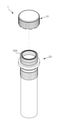
도 1은 본 발명의 일 실시예에 따른 밀폐용기의 용기 캡과 용기 본체를 분리하여 도시한 사시도이다.
도 2는 도 1의 용기 캡의 단면을 도시한 사시도이다.
도 3은 도 1의 용기 캡의 단면도이다.
도 4는 도 1의 용기 본체의 단면도의 일부 확대도이다.
도 5는 도 1의 용기 캡과 용기 본체가 결합된 상태의 단면도의 일부 확대도이다. 1 is a perspective view showing the separation of the container cap and the container body of the sealed container according to an embodiment of the present invention.
Figure 2 is a perspective view showing a cross section of the container cap of Figure 1;
3 is a cross-sectional view of the container cap of FIG. 1 ;
4 is a partially enlarged view of a cross-sectional view of the container body of FIG. 1 .
5 is a partially enlarged view of a cross-sectional view of a state in which the container cap and the container body of FIG. 1 are coupled.
이하, 첨부된 도면을 참조하여 본 발명의 바람직한 여러 실시예들을 상세히 설명하기로 한다.Hereinafter, several preferred embodiments of the present invention will be described in detail with reference to the accompanying drawings.
본 발명의 실시예들은 당해 기술 분야에서 통상의 지식을 가진 자에게 본 발명을 더욱 완전하게 설명하기 위하여 제공되는 것이며, 하기 실시예는 여러 가지 다른 형태로 변형될 수 있으며, 본 발명의 범위가 하기 실시예에 한정되는 것은 아니다. 오히려 이들 실시예들은 본 개시를 더욱 충실하고 완전하게 하고, 당업자에게 본 발명의 사상을 완전하게 전달하기 위하여 제공되는 것이다. 또한, 도면에서 각 층의 두께나 크기는 설명의 편의 및 명확성을 위하여 과장된 것이다.Examples of the present invention are provided to more completely explain the present invention to those of ordinary skill in the art, and the following examples may be modified in various other forms, and the scope of the present invention is as follows It is not limited to an Example. Rather, these embodiments are provided so as to more fully and complete the present disclosure, and to fully convey the spirit of the present invention to those skilled in the art. In addition, in the drawings, the thickness or size of each layer is exaggerated for convenience and clarity of description.
본 명세서에서 사용한 용어는 실시예를 설명하기 위해 사용된 것으로, 개시된 발명을 제한 및/또는 한정하려는 의도가 아니다. 단수의 표현은 문맥상 명백하게 다르게 뜻하지 않는 한, 복수의 표현을 포함한다. 본 명세서에서, "포함하다" 또는 "가지다" 등의 용어는 명세서상에 기재된 특징, 숫자, 단계, 동작, 구성요소, 부품 또는 이들을 조합한 것이 존재함을 지정하려는 것이지, 하나 또는 그 이상의 다른 특징들이나 숫자, 단계, 동작, 구성요소, 부품 또는 이들을 조합한 것들의 존재 또는 부가 가능성을 미리 배제하지 않는다.The terminology used herein is used to describe the embodiments, and is not intended to limit and/or limit the disclosed invention. The singular expression includes the plural expression unless the context clearly dictates otherwise. In the present specification, terms such as “comprise” or “have” are intended to designate that a feature, number, step, operation, component, part, or combination thereof described in the specification exists, but one or more other features It does not preclude the possibility of the presence or addition of numbers, steps, operations, components, parts, or combinations thereof.
본 명세서에서 사용한 "제1", "제2" 등과 같이 서수를 포함하는 용어는 다양한 구성요소들을 설명하는데 사용될 수 있지만, 상기 구성요소들은 상기 용어들에 의해 한정되지는 않으며, 상기 용어들은 하나의 구성요소를 다른 구성요소로부터 구별하는 목적으로만 사용된다. 예를 들어, 본 발명의 권리 범위를 벗어나지 않으면서 제1 구성요소는 제2 구성요소로 명명될 수 있고, 유사하게 제2 구성요소도 제1 구성요소로 명명될 수 있다. As used herein, terms including an ordinal number such as “first”, “second”, etc. may be used to describe various components, but the components are not limited by the terms, and the terms are It is used only for the purpose of distinguishing a component from other components. For example, without departing from the scope of the present invention, a first component may be referred to as a second component, and similarly, a second component may also be referred to as a first component.
이하, 본 발명의 실시예들은 본 발명의 이상적인 실시예들을 개략적으로 도시하는 도면들을 참조하여 설명한다. 도면들에 있어서, 예를 들면, 제조 기술 및/또는 공차(tolerance)에 따라, 도시된 형상의 변형들이 예상될 수 있다. 따라서, 본 발명 사상의 실시예는 본 명세서에 도시된 영역의 특정 형상에 제한된 것으로 해석되어서는 아니 되며, 예를 들면 제조상 초래되는 형상의 변화를 포함하여야 한다.DETAILED DESCRIPTION OF THE PREFERRED EMBODIMENTS Hereinafter, embodiments of the present invention will be described with reference to the drawings schematically illustrating ideal embodiments of the present invention. In the drawings, variations of the illustrated shape can be envisaged, for example depending on manufacturing technology and/or tolerances. Accordingly, embodiments of the spirit of the present invention should not be construed as limited to the specific shape of the region shown in the present specification, but should include, for example, changes in shape caused by manufacturing.
도 1은 본 발명의 일 실시예에 따른 밀폐용기의 용기 캡과 용기 본체를 분리하여 도시한 사시도이고, 도 2는 도 1의 용기 캡의 단면을 도시한 사시도이고, 도 3은 도 1의 용기 캡의 단면도이고, 도 4는 도 1의 용기 본체의 단면도의 일부 확대도이고, 도 5는 도 1의 용기 캡과 용기 본체가 결합된 상태의 단면도의 일부 확대도이다. Figure 1 is a perspective view showing the container cap and the container body of the sealed container separated according to an embodiment of the present invention, Figure 2 is a perspective view showing a cross section of the container cap of Figure 1, Figure 3 is the container of Figure 1 It is a cross-sectional view of the cap, FIG. 4 is a partially enlarged view of a cross-sectional view of the container body of FIG. 1, and FIG. 5 is a partially enlarged view of a cross-sectional view of the container cap and the container body of FIG. 1 in a coupled state.
도 1 내지 도 5를 참조하면, 본 발명의 일 실시예에 따른 밀폐 용기(1)는 용기 본체(20)와 용기 캡(10)을 포함할 수 있다. 1 to 5 , the sealed container 1 according to an embodiment of the present invention may include a
용기 본체(20)는 상단부에 용기 내부에 바이러스 진단 키트나 생체 시료 등을 주입할 수 있는 병목부(200)를 포함할 수 있다. 용기 본체(20)의 병목부(200)의 외주면에는 용기 캡(10)과 결합할 수 있도록 제1 나사산(210)이 형성될 수 있다. The
용기 캡(10)은 용기 본체(20)의 병목부(200)의 외주면에 접하는 외벽부(110)를 포함할 수 있다. 용기 본체(20)의 병목부(200)의 내주면에 접하는 내벽부(120)를 포함할 수 있다. 용기 본체(20)의 병목부(200)는 용기 캡(10)의 외벽부(110)와 내벽부(120)의 사이에 삽입될 수 있다. 용기 캡(10)은 용기 본체(20)의 병목부(200)의 상면을 덮는 상벽부(130)를 포함할 수 있다. 외벽부(110)와 내벽부(120)는 상벽부(130)로부터 하방으로 연장되어 형성될 수 있다. The
용기 캡(10)의 외벽부(110)의 내주면에는 용기 본체(20)의 병목부(200)의 외주면에 형성된 제1 나사산(210)에 접하여 맞물릴 수 있도록 제2 나사산(111)이 형성될 수 있다. 나사산은 첨부가 뾰족하게 형성될 수도 있고, 평탄하게 형성될 수도 있다. A
용기 캡(10)의 내벽부(120)는 용기 본체(20)의 병목부(200)의 내측에 삽입되도록 형성될 수 있다. 용기 캡(10)은 내벽부(120)의 외주면으로부터 반경방향으로 돌출되어 마련되는 제1 돌기(140)를 포함할 수 있다. 용기 캡(10)의 제1 돌기(140)는 용기 본체(20)의 병목부(200)의 내주면에 밀착될 수 있다. 용기 캡(10)의 제1 돌기(140)는 용기 본체(20)에 수용된 내용물이 용기 밖으로 새어 나가거나 용기 본체(20)의 외부의 오염물이 용기 안으로 침투하지 않도록 할 수 있다. The
용기 캡(10)의 내벽부(120)는 상벽부(130)로부터 하방으로 연장되는 강성부(121)를 포함할 수 있다. 용기 캡(10)의 내벽부(120)는 강성부(121)로부터 하방으로 연장되는 탄성부(122)를 포함할 수 있다. 내벽부(120)의 강성부(121)는 강성을 가질 수 있는 소정의 두께로 형성될 수 있다. 내벽부(120)의 탄성부(122)는 외력에 의해 탄성 변형될 수 있도록 형성될 수 있다. 내벽부(120)의 탄성부(122)는 강성부(121)에 비하여 얇은 두께로 형성될 수 있다. 내벽부(120)의 강성부(121)와 탄성부(122)는 같은 내경(A)을 갖도록 마련될 수 있고, 탄성부(122)의 외경(H)이 강성부(121)의 외경(B)보다 작도록 마련될 수 있다. The
용기 캡(10)의 제1 돌기(140)는 내벽부(120)의 탄성부(122)로부터 돌출되도록 마련될 수 있다. 용기 캡(10)의 제1 돌기(140)는 첨부가 둥글게 형성될 수 있다. 용기 캡(10)의 제1 돌기(140)는 첨부의 외경(D)이 용기 본체(20)의 병목부(200)의 내경(E)보다 크게 마련될 수 있다. 용기 캡(10)의 제1 돌기(140)는 첨부의 외경(D)이 내벽부(120)의 강성부(121)의 외경(C)보다 크게 마련될 수 있다. The
용기 캡(10)의 제1 돌기(140)의 첨부의 외경(D)이 용기 본체(20)의 병목부(200)의 내경(E)보다 크기 때문에, 용기 캡(10)이 용기 본체(20)와 결합하였을 때 용기 캡(10)의 내벽부(120)의 탄성부(122)가 반경방향 내측으로 탄성 변형하게 되고, 내벽부(120)의 탄성부(122)의 복원력에 의하여 용기 캡(10)의 제1 돌기(140)는 용기 본체(20)의 병목부(200)의 내주면에 강하게 밀착될 수 있다. 용기 캡(10)의 제1 돌기(140)의 첨부의 외경(D)과 용기 본체(20)의 병목부(200)의 내경(E)의 차이는 0,06mm이상이고 0.14mm 이하가 되는 것이 적합할 수 있다. Since the outer diameter D of the attachment of the
용기 캡(10)은 상벽부(130)의 하면으로부터 하방으로 돌출되어 마련되는 제2 돌기(150)를 포함할 수 있다. 용기 캡(10)의 제2 돌기(150)는 외벽부(110)와 내벽부(120) 사이의 상벽부(130)의 하면으로부터 돌출될 수 있다. 용기 캡(10)과 용기 본체(20)가 결합하였을 때, 용기 캡(10)의 제2 돌기(150)는 용기 본체(20)의 병목부(200)의 상면에 밀착될 수 있다. 용기 캡(10)의 제2 돌기(150)는 용기 본체(20)에 수용된 내용물이 용기 밖으로 새어 나가거나 용기 본체(20)의 외부의 오염물이 용기 안으로 침투하지 않도록 할 수 있다. The
용기 캡(10)의 제2 돌기(150)는 첨부로부터 외벽부(110)의 하단까지의 길이(F)가 용기 본체(20)의 병목부(200)의 길이(G)보다 작도록 돌출될 수 있다. 용기 캡(10)의 제2 돌기(150)의 첨부로부터 외벽부(110)의 하단까지의 길이(F)와 용기 본체(20)의 병목부(200)의 길이(G)의 차이는 0.1mm이상이고 0.5mm 이하가 되는 것이 적합할 수 있다. The
용기 캡(10)의 내벽부(120)의 강성부(121)는 탄성부(122)와 연결된 하단으로부터 상벽부(130)와 연결된 상단까지 상측으로 갈수록 외경이 증가하는 경사면(123)을 포함할 수 있다. 경사면(123)은 최대 외경(C)인 경사면(123)의 상단의 외경(C)이 용기 본체(20)의 병목부(200)의 내경(E)보다 크게 형성될 수 있다. 경사면(123)은 최소 외경(B)인 경사면(123)의 하단의 외경(B)이 용기 본체(20)의 병목부(200)의 내경(E)과 같거나 그보다 작게 형성될 수 있다. The
용기 캡(10)과 용기 본체(20)가 결합하였을 때, 용기 캡(10)의 내벽부(120)의 강성부(121)는 소정의 강성을 가지고 있기 때문에, 용기 본체(20)의 병목부(200)는 용기 캡(10)의 내벽부(120)의 강성부(121)와 외벽부(110)의 사이에 억지 끼워 맞춤식으로 삽입될 수 있고, 용기 캡(10)의 내벽부(120)의 강성부(121)는 용기 본체(20)의 병목부(200)의 내주면에 밀착될 수 있다. When the
용기 캡(10)의 내벽부(120)의 강성부(121)에 마련된 경사면(123)의 최소 외경(B)이 용기 본체(20)의 병목부(200)의 내경(E)과 같거나 그보다 작기 때문에, 용기 본체(20)의 병목부(200)는 용기 캡(10)의 내벽부(120)의 강성부(121)와 외벽부(110)의 사이에 부드럽게 삽입될 수 있다. 용기 캡(10)의 내벽부(120)의 강성부(121)에 마련된 경사면(123)은 용기 본체(20)에 수용된 내용물이 용기 밖으로 새어 나가거나 용기 본체(20)의 외부의 오염물이 용기 안으로 침투하지 않도록 할 수 있다. The minimum outer diameter B of the
본 발명의 일 실시예에 따른 밀폐 용기(1)는 용기 캡(10)의 내벽부(120)의 탄성부(122)에 마련된 제1 돌기(140), 용기 캡(10)의 내벽부(120)의 강성부(121)에 마련된 경사면(123), 및 용기 캡(10)의 상벽부(130)에 마련된 제2 돌기(150)에 의해 3중의 밀폐 구조를 가질 수 있다. 본 발명의 일 실시예에 따른 밀폐 용기(1)는 이러한 구조를 통하여 용기 캡(10)의 내측에 별도의 기밀을 위한 부재를 추가하지 않고도 밀폐 용기(1)의 기밀성을 확보할 수 있다. The sealed container 1 according to an embodiment of the present invention includes a
본 발명은 도면에 도시된 실시예를 참고로 설명되었으나 이는 예시적인 것에 불과하며, 당해 기술분야에서 통상의 지식을 가진 자라면 이로부터 다양한 변형 및 균등한 다른 실시예가 가능하다는 점을 이해할 것이다. 따라서 본 발명의 진정한 기술적 보호 범위는 첨부된 특허청구범위의 기술적 사상에 의하여 정해져야 할 것이다.Although the present invention has been described with reference to the embodiments shown in the drawings, which are merely exemplary, those skilled in the art will understand that various modifications and equivalent other embodiments are possible therefrom. Therefore, the true technical protection scope of the present invention should be determined by the technical spirit of the appended claims.
1: 밀폐 용기
10: 용기 캡
20: 용기 본체
110: 외벽부
120: 내벽부
121: 강성부
122: 탄성부
123: 경사면
130: 상벽부
140: 제1 돌기
150: 제2 돌기
A: 내벽부의 내경
B: 강성부의 최소 외경
C: 강성부의 최대 외경
D: 제1 돌기의 첨부의 외경
E: 병목부의 내경
F: 제2 돌기의 단부로부터 외벽부의 단부까지의 거리
G: 병목부의 높이
H: 탄성부의 외경1: airtight container
10: container cap
20: container body
110: outer wall portion
120: inner wall portion
121: rigid portion
122: elastic part
123: slope
130: upper wall portion
140: first projection
150: second projection
A: The inner diameter of the inner wall part
B: Minimum outer diameter of rigid part
C: the maximum outer diameter of the rigid part
D: outer diameter of attachment of the first projection
E: inner diameter of bottleneck
F: distance from the end of the second projection to the end of the outer wall portion
G: the height of the bottleneck
H: outer diameter of the elastic part
Claims (6)
상기 용기 본체의 병목부에 결합되도록 마련된 용기 캡;을 포함하고,
상기 용기 캡은,
상기 병목부의 외주면에 형성된 나사산에 접하도록, 내주면에 나사산이 형성된 외벽부;
상기 병목부의 내측으로 삽입되는 내벽부;
상기 병목부의 상면을 덮는 상벽부; 및
상기 병목부의 내주면에 밀착될 수 있도록, 상기 내벽부의 외주면으로부터 돌출되어 마련되는 제1 돌기;를 포함하는, 밀폐 용기.a container body including a bottleneck having a screw thread formed on its outer circumferential surface; and
Including; a container cap provided to be coupled to the bottleneck of the container body;
The container cap is
an outer wall portion having a screw thread formed on the inner circumferential surface so as to be in contact with the screw thread formed on the outer circumferential surface of the bottleneck;
an inner wall portion inserted into the bottle neck portion;
an upper wall portion covering an upper surface of the bottle neck portion; and
A sealed container including; a first protrusion provided to protrude from the outer circumferential surface of the inner wall portion so as to be in close contact with the inner circumferential surface of the bottleneck.
상기 용기 캡은, 상기 병목부의 상면에 밀착할 수 있도록, 상기 상벽부의 하면으로부터 돌출되어 마련되는 제2 돌기를 더 포함하는, 밀폐 용기. According to claim 1,
The container cap may further include a second protrusion provided to protrude from a lower surface of the upper wall portion so as to be in close contact with the upper surface of the bottleneck.
상기 용기 캡의 내벽부는,
상기 상벽부로부터 하방으로 연장되는 강성부; 및
상기 강성부로부터 하방으로 연장되고, 탄성 변형이 가능하도록 마련된 탄성부;를 포함하고,
상기 제1 돌기는 상기 탄성부로부터 돌출되어 마련되는, 밀폐 용기.According to claim 1,
The inner wall portion of the container cap,
a rigid portion extending downward from the upper wall portion; and
It includes; an elastic part extending downward from the rigid part and provided to be elastically deformable;
The first protrusion is provided to protrude from the elastic portion, the sealed container.
상기 강성부는 상기 탄성부와 연결된 하단으로부터 상측으로 갈수록 외경이 증가하는 경사면을 포함하고,
상기 경사면은 상단의 외경이 상기 병목부의 내경보다 크게 형성된, 밀폐용기.4. The method of claim 3,
The rigid part includes an inclined surface whose outer diameter increases from the lower end connected to the elastic part toward the upper side,
The inclined surface has an outer diameter of the upper end formed to be larger than the inner diameter of the bottleneck, the sealed container.
상기 탄성부는 상기 강성부의 하단의 두께보다 작은 두께를 가지는, 밀폐용기.4. The method of claim 3,
The elastic portion has a thickness smaller than the thickness of the lower end of the rigid portion, the sealed container.
상기 제1 돌기는,
첨부가 둥글게 형성되고,
상기 첨부의 외경이 상기 용기 본체의 상기 병목부의 내경보다 크게 형성된, 밀폐 용기.According to claim 1,
The first projection,
Attachments are formed round,
An airtight container in which the outer diameter of the attachment is formed larger than the inner diameter of the bottle neck of the container body.
Priority Applications (1)
| Application Number | Priority Date | Filing Date | Title |
|---|---|---|---|
| KR1020200091557A KR20220012594A (en) | 2020-07-23 | 2020-07-23 | Airtight container |
Applications Claiming Priority (1)
| Application Number | Priority Date | Filing Date | Title |
|---|---|---|---|
| KR1020200091557A KR20220012594A (en) | 2020-07-23 | 2020-07-23 | Airtight container |
Publications (1)
| Publication Number | Publication Date |
|---|---|
| KR20220012594A true KR20220012594A (en) | 2022-02-04 |
Family
ID=80267662
Family Applications (1)
| Application Number | Title | Priority Date | Filing Date |
|---|---|---|---|
| KR1020200091557A Ceased KR20220012594A (en) | 2020-07-23 | 2020-07-23 | Airtight container |
Country Status (1)
| Country | Link |
|---|---|
| KR (1) | KR20220012594A (en) |
Cited By (1)
| Publication number | Priority date | Publication date | Assignee | Title |
|---|---|---|---|---|
| WO2024262877A1 (en) * | 2023-06-22 | 2024-12-26 | 최광민 | Cap and container having same |
-
2020
- 2020-07-23 KR KR1020200091557A patent/KR20220012594A/en not_active Ceased
Cited By (1)
| Publication number | Priority date | Publication date | Assignee | Title |
|---|---|---|---|---|
| WO2024262877A1 (en) * | 2023-06-22 | 2024-12-26 | 최광민 | Cap and container having same |
Similar Documents
| Publication | Publication Date | Title |
|---|---|---|
| US10717567B2 (en) | Discharge container | |
| KR101319416B1 (en) | Container assembly and pressure-responsive penetrable cap for the same | |
| US11434050B2 (en) | Stopper for a container for use in freeze-drying processes, and assembly of a stopper and a container | |
| KR101206170B1 (en) | Sealing member for container cap | |
| WO2014065345A1 (en) | Syringe | |
| JP5566765B2 (en) | Vial stopper | |
| KR20220012594A (en) | Airtight container | |
| JP5683129B2 (en) | Vial stopper and seal member used therefor | |
| US6958097B2 (en) | Device for holding and vacuum-sealing a container having an opening | |
| JP4599035B2 (en) | Jug for sample transport | |
| JP6775826B2 (en) | Cap for highly airtight storage container | |
| JPWO2019181978A1 (en) | Drug-filled synthetic resin ampoule and synthetic resin ampoule body used for it | |
| JPH10203546A (en) | Container cap | |
| JP2003063550A (en) | Air-tight container | |
| JP6140532B2 (en) | Container with lid | |
| ZA200610087B (en) | Closing element | |
| CN110023200B (en) | cap for container | |
| US20240269677A1 (en) | Hermetically sealable container for liquids | |
| JP2006273361A (en) | Lid for container | |
| JP3567340B2 (en) | Container with bellows spout | |
| CN115003606B (en) | Coating container | |
| CN220360193U (en) | Skin care product packaging bottle | |
| JP2015085997A (en) | Eye drops container | |
| CN222023218U (en) | Integrated sealing preservation cover | |
| JP2025187335A (en) | cap |
Legal Events
| Date | Code | Title | Description |
|---|---|---|---|
| PA0109 | Patent application |
Patent event code: PA01091R01D Comment text: Patent Application Patent event date: 20200723 |
|
| PA0201 | Request for examination | ||
| E902 | Notification of reason for refusal | ||
| PE0902 | Notice of grounds for rejection |
Comment text: Notification of reason for refusal Patent event date: 20211216 Patent event code: PE09021S01D |
|
| PG1501 | Laying open of application | ||
| E601 | Decision to refuse application | ||
| PE0601 | Decision on rejection of patent |
Patent event date: 20220223 Comment text: Decision to Refuse Application Patent event code: PE06012S01D Patent event date: 20211216 Comment text: Notification of reason for refusal Patent event code: PE06011S01I |