KR20210143210A - Brake system with air blown into grooves in the lining - Google Patents
Brake system with air blown into grooves in the lining Download PDFInfo
- Publication number
- KR20210143210A KR20210143210A KR1020217031946A KR20217031946A KR20210143210A KR 20210143210 A KR20210143210 A KR 20210143210A KR 1020217031946 A KR1020217031946 A KR 1020217031946A KR 20217031946 A KR20217031946 A KR 20217031946A KR 20210143210 A KR20210143210 A KR 20210143210A
- Authority
- KR
- South Korea
- Prior art keywords
- groove
- lining
- braking system
- air
- edge
- Prior art date
- Legal status (The legal status is an assumption and is not a legal conclusion. Google has not performed a legal analysis and makes no representation as to the accuracy of the status listed.)
- Granted
Links
Images




Classifications
-
- F—MECHANICAL ENGINEERING; LIGHTING; HEATING; WEAPONS; BLASTING
- F16—ENGINEERING ELEMENTS AND UNITS; GENERAL MEASURES FOR PRODUCING AND MAINTAINING EFFECTIVE FUNCTIONING OF MACHINES OR INSTALLATIONS; THERMAL INSULATION IN GENERAL
- F16D—COUPLINGS FOR TRANSMITTING ROTATION; CLUTCHES; BRAKES
- F16D65/00—Parts or details
- F16D65/0031—Devices for retaining friction material debris, e.g. dust collectors or filters
-
- F—MECHANICAL ENGINEERING; LIGHTING; HEATING; WEAPONS; BLASTING
- F16—ENGINEERING ELEMENTS AND UNITS; GENERAL MEASURES FOR PRODUCING AND MAINTAINING EFFECTIVE FUNCTIONING OF MACHINES OR INSTALLATIONS; THERMAL INSULATION IN GENERAL
- F16D—COUPLINGS FOR TRANSMITTING ROTATION; CLUTCHES; BRAKES
- F16D65/00—Parts or details
- F16D65/02—Braking members; Mounting thereof
- F16D65/04—Bands, shoes or pads; Pivots or supporting members therefor
- F16D65/092—Bands, shoes or pads; Pivots or supporting members therefor for axially-engaging brakes, e.g. disc brakes
Landscapes
- Engineering & Computer Science (AREA)
- General Engineering & Computer Science (AREA)
- Mechanical Engineering (AREA)
- Braking Arrangements (AREA)
Abstract
본 발명은, 브레이크 패드(10)를 포함하는 제동 시스템으로, 상기 브레이크 패드는 제1 면(13)과 제2 면(14)을 구비하는 백킹 플레이트(1) 및 마찰재로 제작되며 상기 제1 면(13)에 고정된 라이닝(2)을 포함하고, 상기 라이닝(2)은 마찰 면(26), 장착 면(20), 내부 에지(23), 외부 에지(24), 후방 에지(21) 및 전방 에지(22)로 범위가 정해지고, 상기 라이닝(2)에는 상기 마찰 면(26)으로 개방되어 있고, 제1 단부(31)에서 상기 내부 에지(23)를 향한 개구를 구비하며, 제2 단부(32)에서 상기 외부 에지(24)를 향한 개구를 구비하는 적어도 하나의 수집 그루브(3)가 제공되어 있는 제동 시스템에 관한 것이다. 상기 제동 시스템은 공기를 흡입할 수 있는 흡입 파이프(40), 및 공기를 송풍할 수 있는 블로우 파이프(50)를 포함하되, 상기 흡입 파이프(40)의 공기 유입 오리피스(41)는 상기 제1 단부(31) 및 상기 제2 단부(32) 중에서 선택된, 상기 적어도 하나의 수집 그루브(3)의 일 단부의 반대편에 위치하고, 상기 블로우 파이프(50)의 공기 배출 오리피스(51)는 상기 제1 단부(31) 및 상기 제2 단부(32) 중에서 선택된, 상기 적어도 하나의 수집 그루브(3)의 타 단부의 반대편에 위치한다.The present invention is a braking system including a brake pad (10), wherein the brake pad is made of a backing plate (1) having a first surface (13) and a second surface (14) and a friction material, the first surface a lining (2) secured to (13), said lining (2) comprising a friction surface (26), a mounting surface (20), an inner edge (23), an outer edge (24), a rear edge (21) and delimited by a front edge (22), said lining (2) opening to said friction surface (26) and having an opening at a first end (31) towards said inner edge (23), a second The braking system is provided with at least one collecting groove (3) having an opening at its end (32) towards the outer edge (24). The braking system includes an intake pipe 40 capable of sucking air, and a blow pipe 50 capable of blowing air, wherein the air inlet orifice 41 of the intake pipe 40 is disposed at the first end (31) and the second end (32) located opposite one end of the at least one collecting groove (3), the air exhaust orifice (51) of the blow pipe (50) is located at the first end ( 31) and the second end (32), located opposite the other end of the at least one collecting groove (3).
Description
본 발명은 예를 들어 도로 또는 철도 차량, 또는 풍력 터빈과 같이 회전이 감속되어야 하는 회전 요소를 포함하는 기계에 사용하기 위한 무공해 제동 시스템에 관한 것이다.FIELD OF THE INVENTION The present invention relates to a pollution-free braking system for use in machines comprising rotating elements whose rotation is to be reduced, such as, for example, road or rail vehicles, or wind turbines.
이러한 제동 시스템에서, 회전 요소에 대한 브레이크 패드의 마모로 인해, 마찰 제동에 의해 입자 및 먼지가 방출된다. 이 회전 요소는 예를 들어 차량의 바퀴 또는 차량의 바퀴에 의해 구동되는 디스크이다. 이러한 입자가 주변 환경에 분산되어 개인의 건강에 유해한 것으로 알려져 있다. 또한, 자동차용 전동기의 성장으로 마찰 제동 시스템의 마모로 인한 입자 및 먼지 처리의 필요성이 강화되었다. In such braking systems, particles and dust are released by friction braking due to wear of the brake pads against the rotating elements. This rotating element is, for example, a wheel of a vehicle or a disk driven by a wheel of a vehicle. It is known that these particles are dispersed in the surrounding environment and are harmful to personal health. In addition, the growth of electric motors for automobiles has intensified the need to deal with particles and dust caused by wear of friction braking systems.
따라서 이러한 입자와 먼지가 주변 환경으로 방출되기 전에 이들을 포획할 필요가 있다. Therefore, it is necessary to capture these particles and dust before they are released into the environment.
제1 면(13) 및 제2 면(14)을 갖는 백킹 플레이트(1), 및 마찰 재료로 제조되고, 상기 제 1 면(13)에 고정되며, 마찰 면(26), 장착 면(20), 내부 에지(23), 외부 에지(24), 후방 에지(21) 및 전방 에지(22)에 의해 범위가 정해지는 라이닝(2)을 포함하는, 브레이크 패드(10)를 포함하는 제동 시스템을 설명하는 공지된 문서 FR 3,057,040이 있다. 이 라이닝(2)에는 마찰 면(26)에 개방되고, 내부 에지(23)를 향하는 제1 단부에 개구가 있으며, 외부 에지(24)를 향하는 제2 단부(31)에 개구가 있는 적어도 하나의 수집 그루브(3)가 제공되어 있다. 백킹 플레이트(1)는 수집 그루브(3)와 유체 연통하는 홀(17)을 포함한다. 이 홀(17)은 공기와 그루브(3)에서 유동하는 입자 및 먼지를 흡입할 수 있는 흡입 파이프(40)에 의해 흡입 시스템에 연결된다. A backing plate (1) having a first face (13) and a second face (14), and a friction material, fixed to the first face (13), a friction face (26), a mounting face (20) , describes a braking system comprising a
이러한 제동 시스템이 종래 기술을 나타내는 도 10 및 도 11에 도시되어 있다. Such a braking system is shown in FIGS. 10 and 11 , which represent the prior art.
그러나 이러한 제동 시스템에는 단점들이 있다. However, these braking systems have disadvantages.
실제로, 제동 단계에서 바람직하지 않은 양의 입자와 먼지가 계속 빠져 나온다.In fact, during the braking phase, an undesirable amount of particles and dust continues to escape.
본 발명은 이러한 단점을 개선하는 것을 목적으로 한다. The present invention aims to ameliorate these disadvantages.
본 발명은 라이닝 및 회전 요소에 의해 방출되는 입자 및 먼지의 포획이 최적화되고, 구조가 가능한 한 간단한 제동 시스템을 제공하는 것을 목적으로 한다.The present invention aims to provide a braking system in which the entrapment of particles and dust emitted by the lining and rotating elements is optimized and the structure is as simple as possible.
이 목적은, 제동 시스템이 공기가 흡입될 수 있는 흡입 파이프와 공기가 송풍될 수 있는 블로우 파이프를 포함하는 흡입 시스템을 더 포함하되, 상기 흡입 파이프의 공기 유입 오리피스는 제1 단부와 제2 단부 중에서 선택된 적어도 하나의 그루브의 일 단부의 반대편에 위치하고, 블로우 파이프의 공기 배출 오리피스는 제1 단부와 제2 단부 중에서 선택된 그루브의 타 단부의 반대편에 위치한다는 사실에 의해 달성된다. The object is further provided that the braking system further comprises an intake system comprising an intake pipe through which air can be sucked and a blow pipe through which air can be blown, wherein an air inlet orifice of the intake pipe is selected from among a first end and a second end. This is achieved by the fact that the air exhaust orifice of the blow pipe is located opposite one end of the selected at least one groove, and the air exhaust orifice of the blow pipe is located opposite the other end of the groove selected from among the first end and the second end.
이러한 구성으로 인해, 공기의 흡입과 송풍이 동시에 이루어져서 입자 및 먼지를 흡입 파이프 쪽으로 안내할 수 있기 때문에, 흡입 시스템에 의한 입자 및 먼지의 수집이 더욱 효율적으로 된다. 따라서 이러한 입자와 먼지가 대기로 방출되는 것이 최소로 된다. Due to this configuration, the collection of particles and dust by the suction system becomes more efficient because the suction and blowing of air can be made simultaneously to guide the particles and dust towards the suction pipe. The release of these particles and dust into the atmosphere is therefore minimal.
유리하게는, 흡입 파이프나 블로우 파이프는 라이닝 또는 백킹 플레이트와 접촉하지 않는다. Advantageously, the suction pipe or blow pipe does not come into contact with the lining or backing plate.
따라서 제동 단계 후에 라이닝과 패드가 회전 요소에서 멀어질 때 어느 정도 상당한 잔류 토크가 발생하지 않는다. Therefore, no significant residual torque occurs when the linings and pads move away from the rotating element after the braking step.
예를 들어, 흡입 파이프의 공기 유입 오리피스는 제2 단부의 반대편에 위치하고, 블로우 파이프의 공기 배출 오리피스는 제1 단부의 반대편에 위치한다. For example, the air inlet orifice of the intake pipe is opposite the second end and the air outlet orifice of the blow pipe is opposite the first end.
따라서 그루브 내에서 공기는 라이닝의 내부 에지에서 외부 에지로 흐른다. 이 방향은 원심력의 영향에 의한 그루브 내에서 공기의 자연스러운 유동 방향(흡입/송풍이 없음)이므로, 흡입 파이프의 입자 및 먼지 포집이 보다 효율적으로 된다. Thus, within the groove air flows from the inner edge to the outer edge of the lining. This direction is the natural flow direction of air (no suction/blowing) in the groove under the influence of centrifugal force, so the particle and dust collection of the suction pipe becomes more efficient.
유리하게는, 제1 단부는 내부 에지 위로 개방된다. Advantageously, the first end opens over the inner edge.
따라서 공기는 그루브의 연장부 내에서 그루브로부터(흡입 파이프를 향해) 배출되고, 이는 흡입을 더욱 효율적으로 만든다. 또한 흡입 파이프가 라이닝의 주 평면에 위치하기 때문에, 이 파이프를 제동 시스템의 구조에 통합하기 위해 캘리퍼를 수정할 필요가 없다. The air is thus expelled from the groove (toward the suction pipe) within the extension of the groove, which makes the suction more efficient. Also, since the intake pipe is located in the main plane of the lining, there is no need to modify the caliper to incorporate this pipe into the structure of the braking system.
유리하게는, 흡입 파이프의 공기 유입 오리피스가 제1 단부의 반대편에 위치하고, 블로우 파이프의 공기 배출 오리피스는 제2 단부의 반대편에 위치한다. Advantageously, the air inlet orifice of the intake pipe is located opposite the first end and the air outlet orifice of the blow pipe is located opposite the second end.
따라서 그루브 내에서 공기는 라이닝의 외부 에지로부터 내부 에지로 흐른다. Thus in the groove air flows from the outer edge of the lining to the inner edge.
유리하게는, 제2 단부는 외부 에지 위로 개방된다. Advantageously, the second end is open over the outer edge.
따라서 공기는 그루브의 연장부 내에서 그루브로부터(흡입 파이프를 향해) 배출되고, 이는 흡입을 더 효율적으로 되게 한다. 또한 흡입 파이프가 라이닝의 주 평면에 위치하기 때문에, 이 파이프를 제동 시스템의 구조에 통합하기 위해 캘리퍼를 수정할 필요가 없다. The air is thus expelled from the groove (toward the suction pipe) within the extension of the groove, which makes the suction more efficient. Also, since the intake pipe is located in the main plane of the lining, there is no need to modify the caliper to incorporate this pipe into the structure of the braking system.
유리하게는, 흡입 시스템은 펌프 및 필터를 포함하고, 펌프, 필터, 흡입 파이프 및 블로우 파이프는 연속 회로를 형성한다. Advantageously, the suction system comprises a pump and a filter, wherein the pump, filter, suction pipe and blow pipe form a continuous circuit.
따라서 흡입 시스템이 단순화된다. 또한, 필터로 걸러진 공기는 그루브에 취입하는 데에 재사용되어 (필터에 의해 아직 포획되지 않은) 입자들이 여러 번 필터를 통과하게 한다. 따라서 이 필터에 입자가 저장될 확률이 높아진다. Thus, the suction system is simplified. In addition, the filtered air is reused for blowing into the groove, allowing particles (not yet captured by the filter) to pass through the filter several times. Therefore, the probability of particles being stored in this filter is increased.
유리하게는, 적어도 하나의 그루브가 후방 에지 근처에 위치된다. Advantageously, at least one groove is located near the rear edge.
이에 따라 그루브에 의한 입자 및 먼지의 포획이 최적화되고, 이러한 입자 및 먼지는 라이닝의 전면에서 후면으로 흐르는 경향이 있는데, 이는 가동하지 않을 때에 이러한 유동 방향이 라이닝에 대한 회전 요소의 이동 방향이기 때문이다. The entrapment of particles and dust by the grooves is thus optimized, and these particles and dust tend to flow from the front to the back of the lining, since when not in operation this direction of flow is the direction of movement of the rotating element relative to the lining .
유리하게는, 라이닝에는 전방 에지와 후방 에지 사이의 실질적으로 중간에 위치하는 제2 그루브가 제공된다. Advantageously, the lining is provided with a second groove located substantially intermediate between the front edge and the rear edge.
따라서 제동 중 라이닝-디스크 어셈블리의 진동 거동이 개선된다. The vibration behavior of the lining-disc assembly during braking is thus improved.
유리하게는, 라이닝에는 전방 에지 근처에 위치하는 추가 그루브가 제공된다. Advantageously, the lining is provided with an additional groove located near the front edge.
따라서 본 발명에 따른 시스템은 라이닝에 대한 회전 요소의 양방향 회전에서 동등하게 효율적으로 작동하며, 이는 철도 차량과 같이 양방향으로 제동해야 하는 차량에 유리하다.The system according to the invention thus works equally efficiently in the bidirectional rotation of the rotating element relative to the lining, which is advantageous for vehicles that have to brake in both directions, such as railroad cars.
본 발명은 비제한적인 예로서 나타낸 실시형태의 다음의 상세한 설명을 읽을 때 더 잘 이해될 것이고 그 이점이 더 명백해질 것이다. 설명은 다음과 같은 첨부 도면을 참조한다.
도 1은 본 발명에 따른 제동 시스템의 브레이크 패드의 평면도이다.
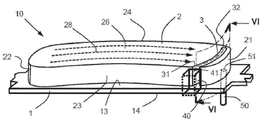
도 2는 본 발명에 따른 제동 시스템의 브레이크 패드의 사시도이다.
도 3은 본 발명에 따른 제동 시스템의 브레이크 패드의 수집 그루브를 따르는, 도 3의 III-III선을 따라 절단한 단면도이다.
도 4는 변형형태에 따른 수집 그루브를 따른 단면도이다.
도 5는 본 발명의 다른 실시형태에 따른 제동 시스템의 브레이크 패드의 사시도이다.
도 6은 본 발명에 따른 제동 시스템의 브레이크 패드의 수집 그루브를 따르는, 도 6의 VI-VI선을 따라 절단한 단면도이다.
도 7은 본 발명의 또 다른 실시형태에 따른 제동 시스템의 브레이크 패드의 평면도이다.
도 8은 회전 디스크에 장착된, 본 발명에 따른 제동 시스템의 사시도이다.
도 9는 본 발명에 따른 제동 장치의 흡입 시스템의 일례의 개략도이다.
도 10은 이미 설명된 종래 기술에 따른 패드의 평면도이다.
도 11은 이미 설명된 종래 기술에 따른 패드의 사시도이다.BRIEF DESCRIPTION OF THE DRAWINGS The invention will be better understood and its advantages will become more apparent upon reading the following detailed description of the embodiments, shown by way of non-limiting example. The description refers to the accompanying drawings as follows.
1 is a plan view of a brake pad of a braking system according to the present invention;
2 is a perspective view of a brake pad of a braking system according to the present invention;
Fig. 3 is a cross-sectional view taken along line III-III of Fig. 3, along the collecting groove of the brake pad of the braking system according to the present invention;
4 is a cross-sectional view along a collection groove according to a modified form.
5 is a perspective view of a brake pad of a braking system according to another embodiment of the present invention;
FIG. 6 is a cross-sectional view taken along line VI-VI of FIG. 6 along the collecting groove of the brake pad of the braking system according to the present invention;
7 is a plan view of a brake pad of a braking system according to another embodiment of the present invention;
8 is a perspective view of a braking system according to the invention, mounted on a rotating disk;
9 is a schematic diagram of an example of an intake system of a braking device according to the invention;
10 is a plan view of a pad according to the prior art already described;
11 is a perspective view of a pad according to the prior art already described;
본 발명은 기계의 회전 요소(9)를 제동하기 위한 브레이크의 브레이크 패드(10)를 포함하는 제동 시스템에 관한 것이다. 이하에서 본 발명은 기계가 이 브레이크가 디스크 브레이크인 도로 차량인 경우에 대해 설명된다. 그러나 본 발명은 레일 위의 차량(철도 차량)에 사용되는 휠 위에 문질러지는 슈 브레이크의 브레이크 패드의 경우 또는 다른 산업 기계(예를 들어 풍력 터빈의 경우)에 사용되는 브레이크 패드의 경우 모두에 균등하게 적용된다. 모든 경우에서, 기계의 회전 요소의 제동은 회전 요소가 회전하는 중에 이 회전 요소 상에서의 브레이크 패드의 마찰에 의해 달성된다. The invention relates to a braking system comprising a brake pad (10) of a brake for braking a rotating element (9) of a machine. Hereinafter, the present invention is explained for the case where the machine is a road vehicle in which the brakes are disc brakes. However, the present invention is equally applicable both in the case of brake pads of shoe brakes rubbed over wheels used in vehicles on rails (railroad vehicles) or in the case of brake pads used in other industrial machines (eg wind turbines). applies. In all cases, braking of the rotating element of the machine is achieved by friction of the brake pads on the rotating element while it is rotating.
디스크 브레이크에서, 제동은 차량의 바퀴와 일체인 디스크(회전 요소(9))와 이 디스크(9)를 샌드위치 하기 위해 양쪽에 하나씩 디스크에 대해 압박되는 두 개의 브레이크 패드(10) 사이의 마찰에 의해 달성된다. 디스크(9)는 주 평면에서 연장되고, 회전축으로서 이 주 평면에 수직인 축(A)을 갖는다. In disc brakes, braking is achieved by friction between a disc (rotating element 9) integral with the wheels of the vehicle and two
패드(10)의 각각은 패드(10)의 두께가 회전축(A)을 따라 연장되도록 이 주 평면에서 연장된다. Each of the
디스크(9)는 디스크(9)의 원주에 접하고 회전 방향(FW)으로 배향되는 접선 방향(T) 및 디스크(9)의 주 평면에서 회전축(A)과 직교하는 반경 방향(R)을 정의하는 회전 방향(FW)으로 회전축(A) 주위를 회전한다. The disk 9 has a tangential direction T tangent to the circumference of the disk 9 and oriented in the direction of rotation FW and a radial direction R orthogonal to the axis of rotation A in the major plane of the disk 9. It rotates around the axis of rotation (A) in the direction of rotation (FW).
이러한 요소들이 도 8에 표시되어 있다. 도 8은 디스크(9)에 장착된 제동 장치를 보여준다. These elements are indicated in FIG. 8 . 8 shows a braking device mounted on the disc 9 .
다음 설명에서 "내부(inner)" 및 "외부(outer)"라는 용어는 각각 회전축(A)에 가장 가깝고 가장 멀리 위치하는 브레이크 패드(10)(또는 그 구성요소)의 에지 또는 영역을 나타내며, "전방(front)" 및 "후방(rear)"이라는 용어는 회전 방향(FW)이기도 한, 라이닝(2)(후술됨)에 의해 방출되는 입자(28)의 흐름 방향에 대해 각각 상류 및 하류에 위치하는 브레이크 패드(10)(또는 그 구성요소)의 에지 또는 영역을 나타낸다. In the following description, the terms "inner" and "outer" denote the edge or area of the brake pad 10 (or a component thereof) located closest to and furthest to the axis of rotation A, respectively, " The terms "front" and "rear" are respectively located upstream and downstream with respect to the flow direction of the
도 1 및 도 2에 도시된 바와 같이, 브레이크 패드(10)는 백플레이트라고도 하는 백킹 플레이트(1)를 포함한다. 백킹 플레이트(1)는 예를 들어 금속으로 만들어진다. 백킹 플레이트(1)는 실질적으로 일정한 두께(예를 들어, 3 내지 7 ㎜)의 평판이고, 그 주 평면에서의 전반적인 형상은 직선 또는 곡선 에지를 갖는 사다리꼴이다. 1 and 2 , the
백킹 플레이트(1)는 라이닝(2)이 고정되는 제1 면(13), 및 제1 면(13)의 반대편에 있는 제2 면(14)을 포함한다. 백킹 플레이트(1)는 또한 2개의 측면 단부에서 백킹 플레이트(1)의 평면 내에서 연장되고, 패드(10)를 유지하고 안내하는 역할을 하는 2개의 이어(11, 12)를 포함한다. The
브레이크 패드(10)는 마찰재로 제작되는 라이닝(2)을 추가로 포함한다. 예를 들어, 이 소재는 "페로도(ferodo)"라는 소재이다. 라이닝(2)은 마찰 면(26)("문지르는" 면), 마찰 면(26) 반대편에 있고, 백킹 플레이트(1)에 고정되는 장착 면(20)(이 두 면은 평행함), 내부 에지(23), 외부 에지(24), 후방 에지(21) 및 전방 에지(22)에 의해 범위가 정해진다. 외부 에지(24), 후방 에지(21) 및 전방 에지(22)는 볼록하거나 직선이고; 내부 에지(23)는 오목하거나 직선이다. 마찰 면(26)은 라이닝(2)이 마모됨에 따라 백킹 플레이트(1)에 점차적으로 접근한다. 따라서 라이닝(2)이 마모됨에 따라 라이닝의 두께(회전축(A)을 따라 측정됨)는 감소한다. 작동하는 중에, 라이닝(2)(및 회전 요소(9))은 라이닝(2)과 디스크(9) 사이의 마찰로 인해 입자(28)를 방출한다. 마찰 면(26)을 따르는 입자(28)의 경로는 도 1 및 도 2에서 점선으로 표시되어 있다. The
라이닝(2)에는 마찰 면(26)으로 개방된 적어도 하나의 수집 그루브(3)가 제공된다. 그루브(3)는 제1 단부(31) 및 제2 단부(32)를 갖는다. 그루브(3)는 제1 단부(31)에 내부 에지(23)를 향한 개구를, 제2 단부(32)에 외부 에지(24)를 향한 개구를 구비한다. The
"그루브(3)가 그 단부에 에지를 향한 개구를 구비한다."는 것은 그루브(3)가 에지 근방의 단부에서 즉 백킹 플레이트(1)를 통해 연장하거나 이 에지 위로 직접 개방됨으로써 연통하는 개구를 구비하는 것으로 이해된다. 모든 경우에서, 그루브 단부들 각각은 마찰 면(26)이 아닌 면 위로 개방된다. "The
그루브(들)(3)의 깊이는 예를 들어 라이닝(2)의 높이와 동일하며, 이는 그루브(3)의 바닥이 백킹 플레이트(1)의 제1 면(13)과 일치함을 의미한다. 이와는 다르게, 그루브(들)(3)의 깊이가 라이닝(2)의 높이보다 작다. 예를 들어, 수집 그루브(들)(3)는 상류 단부로부터 하류 단부까지 일정한 직사각형 단면을 가지며, 이에 따라 일정한 두께를 갖는다. The depth of the groove(s) 3 is, for example, equal to the height of the
예를 들어, 수집 그루브(3)는 후방 에지(21) 부근에 위치한다. 이러한 구성은 입자가 라이닝(2)의 전방에서 후방으로 자연스럽게 흐르는 것을 고려하면, 제동으로 인한 입자/먼지를 이 그루브(3)에 보다 효율적으로 포집할 수 있게 한다. 실제로, 이러한 유동 방향은 정지된 라이닝(2)에 대한 회전 요소(9)의 이동 방향이다. For example, the collecting
선택적으로, 라이닝(2)은 전방 에지(22)와 후방 에지(21) 사이의 실질적으로 중간에 위치하는 제2 수집 그루브(3)를 더 포함한다. Optionally, the
제2 수집 그루브(3)의 이 위치는 라이닝(2)의 바람직하지 않은 진동을 최소화할 수 있게 한다. This position of the
제동 시스템은 공기가 안으로 흡입되는 흡입 파이프(40)와, 공기가 송풍되는 블로우 파이프(50)를 포함하는 흡입 시스템을 포함한다. 흡입 파이프(40)는 제1 단부(31) 및 제2 단부(32) 중에서 선택된, 적어도 하나의 그루브(3)의 일 단부의 반대편에 위치한 공기 유입 오리피스(41)를 포함한다. 블로우 파이프(50)는 제1 단부(31) 및 제2 단부(32) 중에서 선택된, 적어도 하나의 그루브(3)의 타 단부의 반대편에 위치한 공기 배출 오리피스(41)를 포함한다. The braking system comprises an intake system comprising an
이제 도 1 내지 도 4를 참조하여, 흡입 파이프(40)의 공기 유입 오리피스(41)는 제2 단부(32)의 반대편에 위치하고, 블로우 파이프(50)의 공기 배출 오리피스(51)는 제1 단부(31)의 반대편에 위치한 제1 실시형태를 설명한다. 이 실시형태는 흡입 시스템에 의해 강제된 공기의 흐름이 그루브(3) 내의 자연적인 공기 흐름과 동일한 방향으로 발생한다는 이점이 있다. 실제로, 원심력의 영향으로 공기는 제1 단부(31)로부터 제2 단부(32)로 자연스럽게 흐른다. 따라서 흡입 시스템이 더 효율적이다. Referring now to FIGS. 1 to 4 , the
도 1 내지 도 3에 도시된 바와 같이, 그루브(3)는 내부 에지(23) 위로 직접 개방되어 있지 않다. 따라서 라이닝(2)에 의해 형성된 벽은 제1 단부(31)를 내부 에지(23)로부터 분리시키고 있다. 그루브(3)는 백킹 플레이트(1)의 홀(17)을 통해 외부로 개방된다. 이 홀(17)은 백킹 플레이트(1)의 제1 면(13)이 제2 면(14)과 연통하게 배치한다. 블로우 파이프(50)의 배출 오리피스(51)는 제2 면(14)의 홀(17)의 오리피스와 대향한다. 블로우 파이프(50)에 의해 송풍된 공기는 홀(17)을 통해 백킹 플레이트(1)를 횡단하여 그루브(3)로 들어가며, 제1 단부(31)로부터 제2 단부(32)로 흐른다. 외부 에지(24)로 개방되어 있는 제2 단부(32)의 단면은 그루브(3)의 단면과 같다. 흡입 파이프(40)의 공기 유입 오리피스(41)는 그루브(3)의 연장부에 위치한다. 그루브(3) 내를 유동한 공기는 이 유입 오리피스(41)를 통해 흡입 파이프(40)로 들어간다. 1 to 3 , the
대안적으로, 내부 에지(23)에서 그루브(3)는 도 4에 도시된 바와 같이 그루브(3)의 나머지 부분이 내부 에지(23)와 연통하게 위치시키는 채널(90)로 형성된다. 따라서, 이 채널(90)은 라이닝(2)에 의해 둘러싸인 연속적인 측벽을 가지며, 그 제1 단부는 그루브(3)의 나머지 부분 내로 개방되고, 제2 단부(그루브(3)의 제1 단부(31))는 내부 에지(23) 위로 개방된다. 블로우 파이프(50)의 배출 오리피스(51)는 채널(90)의 제2 단부와 마주하고 있다. 공기는 블로우 파이프(50)로부터 그루브의 연장부에 직접 있는 흡입 파이프(40) 쪽으로 (그루브(3)의 길이 방향으로) 유동하여, 흡입 시스템의 효율성을 증가시킨다. 이러한 구성은 라이닝(2)이 마모되는 것을 포함하여 그루브(3)의 공기 흐름을 개선한다. 유리하게는, 채널(90)은, 작동 중에 라이닝(2)의 작업 두께를 최대화하기 위해, 백킹 플레이트(1)에 가능한 한 가깝게 위치한다. Alternatively, the
또한, 백킹 플레이트(1)를 개조할 필요가 없어서(예를 들어, 백킹 플레이트(1)가 그루브(3)의 전체 길이에 걸쳐 연속적이기 때문에, 구멍을 뚫음으로써), 제동 시스템의 제조를 단순화 한다. In addition, there is no need to modify the backing plate 1 (for example by drilling holes as the
채널(90)은 일정한 단면, 예를 들어 원형 단면을 갖는다. 대안적으로, 채널(90)은, 공기가 채널(90)을 통해 그루브(3)에 더 쉽게 들어갈 수 있도록 제1 단부의 단면이 제2 단부의 단면보다 더 크다. The
이제 흡입 파이프(40)의 공기 유입 오리피스(41)는 제1 단부(31)의 반대편에 위치하고, 블로우 파이프(50)의 공기 배출 오리피스(51)는 제2 단부(32)의 반대편에 위치하는, 제2 실시형태를 도 및 도 6을 참고하여 설명한다. Now the
흡입 시스템에 의해 강제되는 공기 흐름은 제2 단부(32)에서 제1 단부(31)를 향한다. The air flow forced by the intake system is directed from the
그루브(3)는 외부 에지(24)에 직접 개방되어 있지 않다. 따라서 라이닝(2)에 의해 형성된 벽은 제2 단부(32)를 외부 에지(24)로부터 분리하고 있다. 그루브(3)는 백킹 플레이트(1)의 홀(17)을 통해 외부로 개방된다. 이 홀(17)은 백킹 플레이트(1)의 제1 면(13)을 제2 면(14)과 연통하게 배치한다. 블로우 파이프(50)의 배출 오리피스(51)는 제2 면(14)에 있는 홀(17)의 오리피스 반대편에 있다. 블로우 파이프(50)에 의해 송풍된 공기는 홀(17)을 통해 백킹 플레이트(1)를 가로질러 그루브(3)로 들어가고, 제2 단부(32)로부터 제1 단부(31)로 흐른다. 내부 에지(23) 위로 개방되어 있는 제1 단부(31)는 그루브(3)의 단면과 동일한 단면을 갖는다. 흡입 파이프(40)의 공기 유입 오리피스(41)는 그루브(3)의 연장부에 위치한다. 그루브(3) 내를 흐르는 공기는 이 유입 오리피스(41)를 통해 흡입 파이프(40)로 들어간다. The
대안적으로, 외부 에지(24)에서, 그루브(3)는 그루브(3)의 나머지 부분이 내부 에지와 연통하게 위치시키는 채널(90)로 형성된다. 따라서, 그루브(3)의 제2 단부(32)는 이 채널(90)을 통해 외부 에지(24) 위로 직접 개방된다. 블로우 파이프(50)의 배출 오리피스(51)는 외부 에지(24)에서 채널(90)의 단부 반대편에 있다. 따라서 블로우 파이프(50)로부터 외부 에지(24)를 거치고 그리고 채널(90)을 통해 그루브(3)로 유입된다. 백킹 플레이트(1)는 그루브(3)의 전체 길이에 걸쳐 연속적이므로 공기가 백킹 플레이트(1)를 통과하지 않는다. Alternatively, at the
유리하게는, 모든 실시형태에서, 흡입 파이프(40) 및 블로우 파이프(50)가 라이닝(2) 또는 백킹 플레이트(1)와 접촉하지 않는다. 이에 따라 제동 단계 이후에, 라이닝(2)과 백킹 플레이트(1)가 회전 요소로부터 멀어질 때 어느 정도 상당한 잔류 토크가 발생되지 않게 된다. 이 잔류 토크는 파이프가 라이닝(2) 또는 백킹 플레이트(1)와 접촉한다는 사실에 의해 발생된다. 이 구성에서, 흡입 파이프(40) 및 블로우 파이프(50)는 백킹 플레이트(1)의 변위 영역(브레이크 패드(10)의 수명 동안 라이닝(2)의 마모로 인한 이 변위의 진폭) 외부에 위치하므로, 브레이크 패드(10)의 전체 사용 수명 동안에 흡입 파이프(40)와 블로우 파이프(50) 어느 것도 라이닝(2) 또는 백킹 플레이트(1)와 접촉하지 않는다. 이 구성에서, 유리하게는, 흡입 파이프(40)의 유입 오리피스(41) 및 블로우 파이프(50)의 배출 오리피스(51)는 또한 경우에 따라 내부 에지(23) 또는 외부 에지(24)에 가능한 한 가깝게 위치하여, 한편으로는 그루브(3)와 다른 한편으로는 흡입 파이프(40) 및 블로우 파이프(50) 사이의 공기의 통과를 최대화한다. Advantageously, in all embodiments, the
도 7은 라이닝(2)에 후방 에지(21) 근처에 위치한 제1 그루브(3)에 추가하여, 전방 에지(22) 근처에 위치한 추가 그루브(3)가 제공되는 경우를 예시한다. 그러면 라이닝(2)은 2개의 그루브(3)를 포함한다. 7 illustrates a case in which the
따라서, 흡입 장치는 제1 그루브(3) 내에서 공기가 유동할 수 있게 하는 제1 블로우 파이프(50) 및 제1 흡입 파이프(40)와, 추가의 그루브(3) 내에서 공기가 유동할 수 있게 하는 제2 블로우 파이프(50) 및 제2 흡입 파이프(40) 포함한다. 이들 파이프 각각은, 각 그루브(3) 내에 공기가 흐르게 할 수 있게 하는 흡입 장치의 일부인 요소에 연결되어 있다. Accordingly, the suction device has a
이러한 이중-그루브(3) 구성은 철도차량과 같이 양방향 제동이 필요한 차량에 적합하다. 실제로, 이 경우에, 회전 요소 상의 라이닝(2)의 마찰에 의해 방출된 입자(28)는 전방 에지(22)에서 후방 에지(21)로 또는 후방 에지(21)에서 전방 에지(22)로 흐를 수 있다. 2개의 그루브의 존재는, 차량의 제동 방향에 관계없이 그루브(3)에 입자를 포획할 수 있도록 한다. This double-groove (3) configuration is suitable for vehicles that require bidirectional braking, such as railroad cars. Indeed, in this case, the
또 다른 실시형태에 따르면, 라이닝(2)은 전방 에지(22)와 후방 에지(21) 사이의 실질적으로 중간에 위치하는 다른 그루브(3)(제2 그루브라고 함)를 포함한다. 이 제2 그루브(3)는 위에서 설명되었다. 전방 에지(22) 근처에 위치한 추가 그루브(3)는 제3 그루브(3)이다. 따라서 이 실시형태는 라이닝(2)의 바람직하지 않은 진동을 최소화하고, 차량의 제동 방향에 관계없이 그루브(3)에 입자를 포착하는 것을 모두 가능하게 한다. According to another embodiment, the
일반적으로 흡입 시스템은 블로우 파이프(50) 내부에 공기를 불어넣을 수 있는 요소와, 흡입 파이프(40)를 통해 공기를 흡입할 수 있는 요소(동일하거나 별도의 요소)를 포함한다. In general, the intake system includes an element capable of blowing air into the
도 9는 펌프(60) 및 필터(70)를 포함하는 펌프(60)(이후 상기 요소임), 펌프(60), 필터(70), 흡입 파이프(40) 및 블로우 파이프(50)가 연속 회로를 형성하는 경우를 예시한다. 예를 들어, 단일 펌프(60)가 있다. 9 shows a continuous circuit in which a pump 60 (hereafter referred to as the above element) comprising a
따라서, 펌프(60), 필터(70), 흡입 파이프(40) 및 블로우 파이프(50)는 그루브(3)와 함께 공기가 폐회로로 흐르는 회로를 형성한다. 따라서 필터(70)에 의해 여과된 공기는 그루브(3)로 불어넣기 위해 재사용되며, 이는 (필터(70)에 의해 이미 포착되지 않은) 입자가 필터(70)를 여러 번 통과하게 한다. 따라서 이 필터(70)에 입자가 저장될 확률이 증가하고 대기로 방출되는 입자 및 먼지의 양이 감소된다. Accordingly, the
변형 예에 따르면, 흡입 시스템은 부분적으로 개방된 회로를 형성하도록 펌프(60), 필터(70), 흡입 파이프(40) 및 블로우 파이프(50), 및 배출 밸브를 포함한다. 이 구성은 그루브(3) 내 입자와 먼지의 수집을 최적화하기 위해, 송풍되는 공기 속도를 흡입 속도로 조정할 수 있다는 장점이 있다. According to a variant, the suction system comprises a
이 변형에서, 흡입 시스템은 솔레노이드 밸브인 배출 밸브를 제어할 수 있는 제어 유닛을 포함한다. 이에 따라 시스템이 최적화될 수 있다. 따라서, 차량의 가속도와 감속도에 따라, 제어 유닛은 송풍을 억제할 수 있다. 예를 들어, 제동 직후 차량을 가속할 때, 그루브(3) 내에 존재하는 입자들을 분산시킬 수 있기 때문에 그루브(3) 내로 공기를 불어넣지 않고, 흡입만 하는 것이 바람직하다. 이 경우, 제어 유닛은, 그루브(3)로 공기를 불어넣지 않고 그로브(3)로부터 흡입하기 위해 배출 밸브를 개방한다. In this variant, the intake system comprises a control unit capable of controlling the discharge valve, which is a solenoid valve. The system can be optimized accordingly. Therefore, according to the acceleration and deceleration of the vehicle, the control unit can suppress blowing. For example, when accelerating the vehicle immediately after braking, it is preferable not to blow air into the
다른 변형 예에 따르면, 흡입 파이프(40)를 통해 공기를 흡입할 수 있는 요소는 유입 오리피스(41)의 하류에서 흡입 파이프(40) 내의 공기의 경로 상에 위치하는 유닛으로, 이는 하류 배출구의 단면적보다 상류 유입구의 단면이 작게 설계된다.According to another variant, the element capable of sucking air through the
Claims (10)
상기 제동 시스템은 공기를 흡입할 수 있는 흡입 파이프(40), 및 공기를 송풍할 수 있는 블로우 파이프(50)를 포함하되, 상기 흡입 파이프(40)의 공기 유입 오리피스(41)는 상기 제1 단부(31) 및 상기 제2 단부(32) 중에서 선택된, 상기 적어도 하나의 수집 그루브(3)의 일 단부의 반대편에 위치하고, 상기 블로우 파이프(50)의 공기 배출 오리피스(51)는 상기 제1 단부(31) 및 상기 제2 단부(32) 중에서 선택된, 상기 적어도 하나의 수집 그루브(3)의 타 단부의 반대편에 위치하는 것을 특징으로 하는 제동 시스템. A braking system including a brake pad (10), wherein the brake pad is made of a backing plate (1) having a first surface (13) and a second surface (14) and a friction material, the first surface (13) a fixed lining (2) comprising a friction surface (26), a mounting surface (20), an inner edge (23), an outer edge (24), a rear edge (21) and a front edge (22) ), the lining ( 2 ) open to the friction surface ( 26 ) and having an opening at a first end ( 31 ) towards the inner edge ( 23 ), a second end ( 32 ) at least one collecting groove (3) having an opening towards the outer edge (24) at
The braking system includes an intake pipe 40 capable of sucking air, and a blow pipe 50 capable of blowing air, wherein the air inlet orifice 41 of the intake pipe 40 has the first end (31) and the second end (32), located opposite one end of the at least one collecting groove (3), the air exhaust orifice (51) of the blow pipe (50) is located at the first end ( 31) and the second end (32), which is located opposite the other end of the at least one collecting groove (3).
흡입 파이프(40) 및 블로우 파이프(50) 중 어느 것도 상기 라이닝(2) 또는 상기 백킹 플레이트(1)와 접촉하지 않는 것을 특징으로 하는 제동 시스템. According to claim 1,
Braking system, characterized in that neither the suction pipe (40) nor the blow pipe (50) is in contact with the lining (2) or the backing plate (1).
상기 흡입 파이프(40)의 공기 유입 오리피스(41)는 상기 제2 단부(32) 반대편에 위치하고, 상기 블로우 파이프(50)의 공기 배출 오리피스(51)는 상기 제1 단부(31) 반대편에 위치하는 것을 특징으로 하는 제동 시스템. 3. The method of claim 1 or 2,
The air inlet orifice 41 of the intake pipe 40 is located opposite the second end 32, and the air outlet orifice 51 of the blow pipe 50 is located opposite the first end 31 A braking system, characterized in that.
상기 제1 단부(31)는 상기 내부 에지(23) 위로 개방되어 있는 것을 특징으로 하는 제동 시스템. 4. The method of claim 3,
Braking system, characterized in that the first end (31) is open above the inner edge (23).
상기 흡입 파이프(40)의 공기 유입 오리피스(41)는 상기 제1 단부(31) 반대편에 위치하고, 상기 블로우 파이프(50)의 공기 배출 오리피스(51)는 상기 제2 단부(32) 반대편에 위치하는 것을 특징으로 하는 제동 시스템. 3. The method of claim 1 or 2,
The air inlet orifice 41 of the intake pipe 40 is located opposite the first end 31 , and the air outlet orifice 51 of the blow pipe 50 is located opposite the second end 32 . A braking system, characterized in that.
상기 제2 단부(32)는 상기 외부 에지(24) 위로 개방되어 있는 것을 특징으로 하는 제동 시스템. 6. The method of claim 5,
and the second end (32) is open above the outer edge (24).
상기 흡입 시스템은 펌프(60) 및 필터(70)를 포함하고, 상기 펌프(60), 상기 필터(70), 상기 흡입 파이프(40) 및 상기 블로우 파이프(50)는 연속된 회로를 형성하는 것을 특징으로 하는 제동 시스템. 7. The method according to any one of claims 1 to 6,
The suction system includes a pump 60 and a filter 70, and the pump 60, the filter 70, the suction pipe 40 and the blow pipe 50 form a continuous circuit. Features a braking system.
상기 적어도 하나의 그루브(3)는 상기 후방 에지(21) 근처에 위치하는 것을 특징으로 하는 제동 시스템. 8. The method according to any one of claims 1 to 7,
Braking system, characterized in that the at least one groove (3) is located near the rear edge (21).
상기 라이닝(2)에는 상기 전방 에지(22)와 상기 후방 에지(21) 사이의 실질적으로 중간에 위치하는 제2 그루브(3)가 제공되어 있는 것을 특징으로 하는 제동 시스템. 9. The method of claim 8,
Braking system, characterized in that the lining (2) is provided with a second groove (3) located substantially intermediate between the front edge (22) and the rear edge (21).
상기 라이닝(2)에는 상기 전방 에지(22) 근처에 위치하는 추가의 그루브(3)가 제공되어 있는 것을 특징으로 하는 제동 시스템.10. The method according to claim 8 or 9,
Braking system, characterized in that the lining (2) is provided with an additional groove (3) located near the front edge (22).
Applications Claiming Priority (3)
| Application Number | Priority Date | Filing Date | Title |
|---|---|---|---|
| FRFR1903216 | 2019-03-28 | ||
| FR1903216A FR3094428B1 (en) | 2019-03-28 | 2019-03-28 | Braking system with blowing in the lining groove |
| PCT/EP2020/058815 WO2020193775A1 (en) | 2019-03-28 | 2020-03-27 | Braking system with air blowing in the groove in the lining |
Publications (2)
| Publication Number | Publication Date |
|---|---|
| KR20210143210A true KR20210143210A (en) | 2021-11-26 |
| KR102843828B1 KR102843828B1 (en) | 2025-08-07 |
Family
ID=67514845
Family Applications (1)
| Application Number | Title | Priority Date | Filing Date |
|---|---|---|---|
| KR1020217031946A Active KR102843828B1 (en) | 2019-03-28 | 2020-03-27 | A braking system in which air is injected into grooves within the lining |
Country Status (9)
| Country | Link |
|---|---|
| US (1) | US12060913B2 (en) |
| EP (1) | EP3948004B1 (en) |
| JP (1) | JP7475069B2 (en) |
| KR (1) | KR102843828B1 (en) |
| CN (1) | CN113631823B (en) |
| CA (1) | CA3134070C (en) |
| FR (1) | FR3094428B1 (en) |
| SG (1) | SG11202110740XA (en) |
| WO (1) | WO2020193775A1 (en) |
Families Citing this family (6)
| Publication number | Priority date | Publication date | Assignee | Title |
|---|---|---|---|---|
| FR3094429B1 (en) * | 2019-03-28 | 2021-04-16 | Tallano Tech | Braking system with centrifugal suction in the lining groove |
| FR3125267B1 (en) * | 2021-07-16 | 2023-07-28 | Tallano Tech | Friction assembly with connector block and suction circuit |
| EP4174339B1 (en) | 2021-10-27 | 2024-08-28 | KNORR-BREMSE Systeme für Nutzfahrzeuge GmbH | Disc brake, brake pad and brake system comprising the disc brake and brake pads |
| FR3142787B1 (en) * | 2022-12-02 | 2024-11-29 | Tallano Tech | Inclined air inlet drilling |
| FR3160746B1 (en) * | 2024-04-02 | 2026-03-13 | Tallano Tech | Brake pads |
| EP4682396A1 (en) * | 2024-07-16 | 2026-01-21 | Volvo Truck Corporation | Disc braking system |
Citations (5)
| Publication number | Priority date | Publication date | Assignee | Title |
|---|---|---|---|---|
| KR19980061265A (en) * | 1996-12-31 | 1998-10-07 | 박병재 | Dust absorption device of brake ped |
| KR20040033884A (en) * | 2002-10-16 | 2004-04-28 | 현대자동차주식회사 | dust filtering device of brake pad in a vehicle |
| JP2007192268A (en) * | 2006-01-18 | 2007-08-02 | Toyota Motor Corp | Disc brake device and brake pad |
| GB2533476A (en) * | 2014-12-17 | 2016-06-22 | Michael Mennie Trevor | Brake pad assembly |
| CN109307029A (en) * | 2018-10-16 | 2019-02-05 | 盐城市天驰汽配有限公司 | A kind of brake block with dust filtering structure |
Family Cites Families (13)
| Publication number | Priority date | Publication date | Assignee | Title |
|---|---|---|---|---|
| JPS6040905Y2 (en) * | 1978-12-22 | 1985-12-11 | トヨタ自動車株式会社 | Disc brake drag prevention device |
| DE4401846A1 (en) | 1994-01-22 | 1995-07-27 | Teves Gmbh Alfred | Friction lining for disc brake |
| KR19980041410U (en) | 1996-12-23 | 1998-09-15 | 박병재 | Automobile brake pad dust removal device |
| DE19846887C2 (en) | 1998-10-13 | 2000-11-30 | Wolfgang Foesel | Brake system for a motor vehicle |
| JP2005036829A (en) * | 2003-07-15 | 2005-02-10 | Mitsubishi Electric Corp | Friction brake device |
| GB2492858C2 (en) | 2011-12-06 | 2014-12-10 | Trevor Michael Mennie | Brake system |
| JP2013144585A (en) | 2012-01-13 | 2013-07-25 | Mitsubishi Electric Corp | Disk brake device for elevator winding machine, and powder dust removing method |
| PL225371B1 (en) | 2012-10-26 | 2017-04-28 | Przemysłowy Inst Motoryzacji | Device to reduce dust emissions during vehicle braking, equipped with a brake drum brake and a system comprising such a device |
| FR2997743B1 (en) | 2012-11-08 | 2016-04-29 | Tallano Tech | PARTICLE CAPTRATING BRAKE ASSEMBLY |
| FR3046644B1 (en) * | 2016-01-13 | 2019-04-12 | Tallano Technologie | PARTICLE CAPTRATING BRAKE ASSEMBLY WITH DEFLECTOR |
| FR3057040B1 (en) | 2016-10-05 | 2019-05-03 | Tallano Technologie | BRAKE PAD AND PARTICLE CAPTRATING BRAKE ASSEMBLY |
| FR3069832B1 (en) * | 2017-08-01 | 2019-09-06 | Tallano Technologie | FRICTION ASSEMBLY FOR RAIL BRAKING SYSTEM |
| CN207111793U (en) * | 2017-08-10 | 2018-03-16 | 桐庐宇鑫汽配有限公司 | A kind of self-skimming formula brake block structure |
-
2019
- 2019-03-28 FR FR1903216A patent/FR3094428B1/en active Active
-
2020
- 2020-03-27 EP EP20713052.7A patent/EP3948004B1/en active Active
- 2020-03-27 CA CA3134070A patent/CA3134070C/en active Active
- 2020-03-27 KR KR1020217031946A patent/KR102843828B1/en active Active
- 2020-03-27 JP JP2021557516A patent/JP7475069B2/en active Active
- 2020-03-27 WO PCT/EP2020/058815 patent/WO2020193775A1/en not_active Ceased
- 2020-03-27 SG SG11202110740XA patent/SG11202110740XA/en unknown
- 2020-03-27 US US17/598,822 patent/US12060913B2/en active Active
- 2020-03-27 CN CN202080024182.XA patent/CN113631823B/en active Active
Patent Citations (5)
| Publication number | Priority date | Publication date | Assignee | Title |
|---|---|---|---|---|
| KR19980061265A (en) * | 1996-12-31 | 1998-10-07 | 박병재 | Dust absorption device of brake ped |
| KR20040033884A (en) * | 2002-10-16 | 2004-04-28 | 현대자동차주식회사 | dust filtering device of brake pad in a vehicle |
| JP2007192268A (en) * | 2006-01-18 | 2007-08-02 | Toyota Motor Corp | Disc brake device and brake pad |
| GB2533476A (en) * | 2014-12-17 | 2016-06-22 | Michael Mennie Trevor | Brake pad assembly |
| CN109307029A (en) * | 2018-10-16 | 2019-02-05 | 盐城市天驰汽配有限公司 | A kind of brake block with dust filtering structure |
Also Published As
| Publication number | Publication date |
|---|---|
| CN113631823A (en) | 2021-11-09 |
| CN113631823B (en) | 2023-03-14 |
| US20220178410A1 (en) | 2022-06-09 |
| FR3094428A1 (en) | 2020-10-02 |
| EP3948004B1 (en) | 2023-05-10 |
| EP3948004A1 (en) | 2022-02-09 |
| US12060913B2 (en) | 2024-08-13 |
| CA3134070A1 (en) | 2020-10-01 |
| KR102843828B1 (en) | 2025-08-07 |
| SG11202110740XA (en) | 2021-10-28 |
| JP7475069B2 (en) | 2024-04-26 |
| JP2022527167A (en) | 2022-05-31 |
| WO2020193775A1 (en) | 2020-10-01 |
| CA3134070C (en) | 2024-01-02 |
| FR3094428B1 (en) | 2021-04-16 |
Similar Documents
| Publication | Publication Date | Title |
|---|---|---|
| KR102843828B1 (en) | A braking system in which air is injected into grooves within the lining | |
| JP7424655B2 (en) | Brake pads with particulate and dust collection | |
| KR102815391B1 (en) | Braking system with centrifugal suction in the grooves of the lining | |
| JP6953522B2 (en) | Brake pads and brake units for capturing dust | |
| RU2644037C2 (en) | Braking device with particle catcher | |
| JP2017125610A (en) | Particle trapping brake assembly with deflector | |
| WO2017073574A1 (en) | Disc-brake device | |
| JP2007192268A (en) | Disc brake device and brake pad | |
| HK40055150A (en) | Braking system with air blowing in the groove in the lining | |
| HK40055150B (en) | Braking system with air blowing in the groove in the lining | |
| RU2796288C2 (en) | Braking system with air injection into the groove | |
| HK40055151B (en) | Braking system with centrifugal suction in the groove of the lining | |
| HK40055151A (en) | Braking system with centrifugal suction in the groove of the lining | |
| RU2790343C2 (en) | Brake pad with collection of particles and dust | |
| RU2788098C1 (en) | Brake system with centrifugal suction in the lining groove | |
| CN120202358A (en) | Slanted holes for air inlet | |
| EP4480764A1 (en) | Brake dust collector | |
| HK40052446B (en) | Brake pad which collects particles and dust | |
| HK40052446A (en) | Brake pad which collects particles and dust | |
| KR20230010960A (en) | Brake Dust Particle Collector Utilizing Compressed Air And Therein | |
| HK40120764A (en) | Angled air-intake bore | |
| HK40003039B (en) | Brake pad and braking unit for capturing particles |
Legal Events
| Date | Code | Title | Description |
|---|---|---|---|
| PA0105 | International application |
St.27 status event code: A-0-1-A10-A15-nap-PA0105 |
|
| PG1501 | Laying open of application |
St.27 status event code: A-1-1-Q10-Q12-nap-PG1501 |
|
| PA0201 | Request for examination |
St.27 status event code: A-1-2-D10-D11-exm-PA0201 |
|
| R18-X000 | Changes to party contact information recorded |
St.27 status event code: A-3-3-R10-R18-oth-X000 |
|
| E902 | Notification of reason for refusal | ||
| PE0902 | Notice of grounds for rejection |
St.27 status event code: A-1-2-D10-D21-exm-PE0902 |
|
| P11-X000 | Amendment of application requested |
St.27 status event code: A-2-2-P10-P11-nap-X000 |
|
| E701 | Decision to grant or registration of patent right | ||
| PE0701 | Decision of registration |
St.27 status event code: A-1-2-D10-D22-exm-PE0701 |
|
| F11 | Ip right granted following substantive examination |
Free format text: ST27 STATUS EVENT CODE: A-2-4-F10-F11-EXM-PR0701 (AS PROVIDED BY THE NATIONAL OFFICE) |
|
| PR0701 | Registration of establishment |
St.27 status event code: A-2-4-F10-F11-exm-PR0701 |
|
| PR1002 | Payment of registration fee |
St.27 status event code: A-2-2-U10-U12-oth-PR1002 Fee payment year number: 1 |
|
| U12 | Designation fee paid |
Free format text: ST27 STATUS EVENT CODE: A-2-2-U10-U12-OTH-PR1002 (AS PROVIDED BY THE NATIONAL OFFICE) Year of fee payment: 1 |
|
| PG1601 | Publication of registration |
St.27 status event code: A-4-4-Q10-Q13-nap-PG1601 |
|
| Q13 | Ip right document published |
Free format text: ST27 STATUS EVENT CODE: A-4-4-Q10-Q13-NAP-PG1601 (AS PROVIDED BY THE NATIONAL OFFICE) |