KR20210125730A - power generation unit to engine by mobile rotation piston. - Google Patents
power generation unit to engine by mobile rotation piston. Download PDFInfo
- Publication number
- KR20210125730A KR20210125730A KR1020200043269A KR20200043269A KR20210125730A KR 20210125730 A KR20210125730 A KR 20210125730A KR 1020200043269 A KR1020200043269 A KR 1020200043269A KR 20200043269 A KR20200043269 A KR 20200043269A KR 20210125730 A KR20210125730 A KR 20210125730A
- Authority
- KR
- South Korea
- Prior art keywords
- cylinder
- piston
- engine
- rotary piston
- valve
- Prior art date
- Legal status (The legal status is an assumption and is not a legal conclusion. Google has not performed a legal analysis and makes no representation as to the accuracy of the status listed.)
- Ceased
Links
Images




Classifications
-
- F—MECHANICAL ENGINEERING; LIGHTING; HEATING; WEAPONS; BLASTING
- F02—COMBUSTION ENGINES; HOT-GAS OR COMBUSTION-PRODUCT ENGINE PLANTS
- F02B—INTERNAL-COMBUSTION PISTON ENGINES; COMBUSTION ENGINES IN GENERAL
- F02B53/00—Internal-combustion aspects of rotary-piston or oscillating-piston engines
- F02B53/02—Methods of operating
-
- F—MECHANICAL ENGINEERING; LIGHTING; HEATING; WEAPONS; BLASTING
- F02—COMBUSTION ENGINES; HOT-GAS OR COMBUSTION-PRODUCT ENGINE PLANTS
- F02B—INTERNAL-COMBUSTION PISTON ENGINES; COMBUSTION ENGINES IN GENERAL
- F02B53/00—Internal-combustion aspects of rotary-piston or oscillating-piston engines
- F02B53/04—Charge admission or combustion-gas discharge
-
- F—MECHANICAL ENGINEERING; LIGHTING; HEATING; WEAPONS; BLASTING
- F02—COMBUSTION ENGINES; HOT-GAS OR COMBUSTION-PRODUCT ENGINE PLANTS
- F02B—INTERNAL-COMBUSTION PISTON ENGINES; COMBUSTION ENGINES IN GENERAL
- F02B53/00—Internal-combustion aspects of rotary-piston or oscillating-piston engines
- F02B53/10—Fuel supply; Introducing fuel to combustion space
-
- F—MECHANICAL ENGINEERING; LIGHTING; HEATING; WEAPONS; BLASTING
- F02—COMBUSTION ENGINES; HOT-GAS OR COMBUSTION-PRODUCT ENGINE PLANTS
- F02B—INTERNAL-COMBUSTION PISTON ENGINES; COMBUSTION ENGINES IN GENERAL
- F02B55/00—Internal-combustion aspects of rotary pistons; Outer members for co-operation with rotary pistons
- F02B55/02—Pistons
-
- F—MECHANICAL ENGINEERING; LIGHTING; HEATING; WEAPONS; BLASTING
- F02—COMBUSTION ENGINES; HOT-GAS OR COMBUSTION-PRODUCT ENGINE PLANTS
- F02B—INTERNAL-COMBUSTION PISTON ENGINES; COMBUSTION ENGINES IN GENERAL
- F02B55/00—Internal-combustion aspects of rotary pistons; Outer members for co-operation with rotary pistons
- F02B55/02—Pistons
- F02B55/04—Cooling thereof
-
- F—MECHANICAL ENGINEERING; LIGHTING; HEATING; WEAPONS; BLASTING
- F02—COMBUSTION ENGINES; HOT-GAS OR COMBUSTION-PRODUCT ENGINE PLANTS
- F02B—INTERNAL-COMBUSTION PISTON ENGINES; COMBUSTION ENGINES IN GENERAL
- F02B55/00—Internal-combustion aspects of rotary pistons; Outer members for co-operation with rotary pistons
- F02B55/08—Outer members for co-operation with rotary pistons; Casings
-
- Y—GENERAL TAGGING OF NEW TECHNOLOGICAL DEVELOPMENTS; GENERAL TAGGING OF CROSS-SECTIONAL TECHNOLOGIES SPANNING OVER SEVERAL SECTIONS OF THE IPC; TECHNICAL SUBJECTS COVERED BY FORMER USPC CROSS-REFERENCE ART COLLECTIONS [XRACs] AND DIGESTS
- Y02—TECHNOLOGIES OR APPLICATIONS FOR MITIGATION OR ADAPTATION AGAINST CLIMATE CHANGE
- Y02T—CLIMATE CHANGE MITIGATION TECHNOLOGIES RELATED TO TRANSPORTATION
- Y02T10/00—Road transport of goods or passengers
- Y02T10/10—Internal combustion engine [ICE] based vehicles
- Y02T10/12—Improving ICE efficiencies
Landscapes
- Engineering & Computer Science (AREA)
- Chemical & Material Sciences (AREA)
- Combustion & Propulsion (AREA)
- Mechanical Engineering (AREA)
- General Engineering & Computer Science (AREA)
- Shafts, Cranks, Connecting Bars, And Related Bearings (AREA)
- Transmission Devices (AREA)
Abstract
본 발명은 화석연료인 가솔린, 수소가스를 연료로 하는 내연기관으로 한 쌍의 회전피스톤이 하우징 (150)내를 360도 회전하며 회전동력을 발생시키는 회전피스톤 내연기관.
[색인어] 1. A기통 연소실 (110), 2. B기통 연소실 (120), 3. A기통 회전피스톤 (130), 4 B기통 회전피스톤 (140). 하우징 (150).The present invention is an internal combustion engine using fossil fuels such as gasoline and hydrogen gas as fuel, and a rotating piston internal combustion engine in which a pair of rotating pistons rotate 360 degrees in a housing 150 to generate rotational power.
[Index] 1. A cylinder combustion chamber (110), 2. B cylinder combustion chamber (120), 3. A cylinder rotary piston (130), 4 B cylinder rotary piston (140). housing (150).
Description
본 발명 회전피스톤 (rotary piston) 내연기관 과 피스톤 (piston) 왕복식 내연기관, 두 기관 기초이론 비교 설명을 하기 위해 피스톤왕복식 기관 크랭크축, 본 발명 회전피스톤기관 회전축 같은 회전반경 같은 부하가 걸려있는 두 기관 어느 기관에서 고출력을 낼 수 있는지 기계적 효율 실험을 하였다. 조금은 부하가 걸려있는 피스톤 왕복식 단기통 내연기관을 가지고, 최대한 마찰력을 줄이기 위해 피스톤링, 캠샤후트, 흡입 배기 밸브, 스프링 등을 제거 후 폭발 압이 아닌 무계 (그램) 단위 힘으로 피스톤을 아래로 내려 미는 (도9, 1~18번 참조) 에서와 같이 크랭크축 핀 (crank pin) 각도별 각각 고출력을 낼 수 있는지 기관 효율 실험을 하였다. 효율 실험 수치는 아래와 같다. (도면9 참조) 도9, 1번 90도각 피스톤 (piston) 과 커넥팅-로드 (connecting rod) 크랭크 핀이 수평 수직각 1직선상에서는 피스톤을 무한대의 힘으로 내려 밀어도 크랭크 (crank shaft) 축을 회전을 시킬 수 없다. 수직각을 지나 도9, 2번 80도 각에서는 4.264 (그램)의 많은 압력으로 피스톤을 내려 밀어야 크랭크축을 회전시킬 수가 있었고, 도9, 3번 70도 각에서는 1.404 압력으로 피스톤을 아래로 내려 밀어야 크랭크축을 회전시킬 수가 있었고, 60도 각에서는 780, 50도 각에서는 572, 40도 각에서는 468, 30도 각에서는 416, 20도 각과 10도 각에서는 364, 여기에서 가장적은 압력으로 크랭크축을 회전시킬 수가 있었다. 10도 각에서는 364, 0도에서는 416, -10도 각에서는 468, -20도 각에서는 520, -30도에서는 674, -40도 각에서는 780, -50도에서는 1.040, -60도에서는 1.560, -70도에서는 2.964, -80도 각에서는 8.060 그램 이상 압력으로 피스톤을 내려 밀어야 크랭크축을 최초 회전시킬 수가 있었다.A rotary piston internal combustion engine of the present invention and a piston reciprocating internal combustion engine, a crankshaft of a reciprocating piston engine and a rotating shaft of the present invention to explain the basic theory of the two engines, a load with the same rotational radius is applied The mechanical efficiency test was conducted to see which of the two institutions can produce high output. Having a piston reciprocating single-cylinder internal combustion engine with a slight load, remove the piston ring, camshaft, intake exhaust valve, spring, etc. to reduce friction as much as possible. As shown in Fig. 9, No. 1 to 18, an engine efficiency test was performed to see if each angle of the crank pin could produce a high output. Efficiency test values are as follows. (See Fig. 9) Fig. 9, No. 1 90 degree angle piston and connecting rod When the crank pin is horizontally and vertically 1 straight, the crank shaft rotates even when the piston is pushed down with infinite force. can't do it 9 and 2, at the 80 degree angle, the crankshaft could be rotated by pushing the piston down with a large pressure of 4.264 (grams), and at the 70 degree angle of FIGS. 9 and 3, the piston had to be pushed down with 1.404 pressure The crankshaft could be rotated, 780 at 60 degrees, 572 at 50 degrees, 468 at 40 degrees, 416 at 30 degrees, 364 at 20 and 10 degrees, where you can rotate the crankshaft with the least amount of pressure. could have 364 at 10 degrees, 416 at 0 degrees, 468 at -10 degrees, 520 at -20 degrees, 674 at -30 degrees, 780 at -40 degrees, 1.040 at -50 degrees, 1.560 at -60 degrees, At -70 degrees, the crankshaft could be rotated for the first time by pushing the piston down with a pressure of 2.964 or more at -80 degrees and 8.060 grams at an angle of -80 degrees.
일반적으로 피스톤 왕복식 기관에서 피스톤이 실린더 상사점에 도달, 폭발력이 발생되면 크랭크축 핀 각도와는 관계없이 처음부터 강한 폭발력으로 크랭크축을 회전시키는 것으로 알고 있지만 실제 이론에서는 상기 실험 수치에서와 같이 그렇지 않다. 크랭크 핀 각도별 다, 다른 압력으로 크랭크 축을 회전시킨다. (도9, 1~18번 참조) 도9, 1번의 경우 크랭크축이 최초 회전이 시작되기 위해서는 수평 수직각에서 0.1도 라도 시계방향으로 또는 반시계방향으로 지나서부터 회전이 시작되기 때문이다. 수직각을 지난 도9, 2번 80도 각에서는 4.264 (그램) 의 많은 압력으로 피스톤을 내려 밀어야 크랭크축을 회전시킬 수 있다면 도9, 8번 20도 각에서와 같이 크랭크 핀 각과 커넥팅로드 각이 (ㄱ)자 각이 형성 될 때 (ㄱ)자의 왼쪽이 커넥팅로드가 되고 (ㄱ)자가 꺾이는 부분이 크랭크 핀이 되고, (ㄱ)자 아래 끝 쪽이 크랭크 중심축이 될 때 도9, 8번 20도 각에서는 364의 가장 적은 내려 미는 압력으로 크랭크축을 회전 시킬 수가 있었다. 여기에서 이론이 본 발명 이론으로 (도11f, 도11g B기통참조) 도11f와 도11g 과정에서 완전 연소된 폭발압은 B기통 회전피스톤 (140)이 시계 방향으로 회전하게 되면 도11g 후반에서 B기통 연소실 (120)이 열리기 시작하여 도11g와 도11h 과정에서 폭발압은 A기통 회전피스톤 (130)을 등지고 B기통 회전피스톤 (140)을 208 압력으로 시계방향으로 밀어낸다. 이때 B기통 회전피스톤 (140) 중심축과 B기통 회전피스톤 (140) 회전방향 뒤쪽을 미는 폭발압 방향각이 (ㄱ)자각 이론으로 (도9, 8번 20도,) 각과 같다. 피스톤 왕복식 기관, 본 발명 회전피스톤 기관에서 같은 규격 같은 회전반경 같은 부하 같은 조건에서 피스톤왕복식 기관에서는 364 압력으로 크랭크 축을 회전시키고 본 발명기관에서는 같은 규격 같은 회전반경 같은 부하에서 208 압력으로 회전피스톤 축을 회전시킨다. 364-208=156, 156 차이점이 발생하는 이유는 피스톤 왕복식기관 피스톤은 수직으로 내려밀고 커넥팅 로드는 시계방향으로 밀기 때문이다. 각각 방향각이 다르기 때문이다.In general, in a piston reciprocating engine, when the piston reaches cylinder top dead center and an explosive force is generated, it is known that the crankshaft rotates with a strong explosive force from the beginning regardless of the crankshaft pin angle, but in actual theory, this is not the case as in the experimental figures above. . Each crankpin angle rotates the crankshaft with different pressures. (See FIGS. 9 and 1 to 18) In the case of FIGS. 9 and 1, in order for the crankshaft to start rotating for the first time, it is because the rotation starts after passing clockwise or counterclockwise even by 0.1 degree from the horizontal and vertical angle. At the 80 degree angle of FIGS. 9 and 2, past the vertical angle, if the crankshaft can be rotated by pushing the piston down with a large pressure of 4.264 (grams), the crank pin angle and the connecting rod angle ( a) When the left side of the (a) shape becomes the connecting rod, the bent part of the (a) shape becomes the crank pin, and the lower end of the (a) shape becomes the crank center shaft Fig. 9, 8 No. 20 In the angle, it was possible to rotate the crankshaft with the lowest pushing pressure of 364. Here, the theory is the theory of the present invention (see Fig. 11f, Fig. 11g cylinder B). The explosive pressure completely burned in the process of Figs. 11f and 11g is B in the latter half of Fig. 11g when the rotating
아래의 실험수치는 피스톤 왕복식 기관과, 본 발명 회전피스톤 기관 각도별 피스톤을 내려 미는 힘의 세기는 아래와 같다. 이론 공식이 있어 계산된 정확한 실험수치가 아닌 무계 (그램) 단위를 가지고 피스톤을 아래로 내려 미는 크랭크 축 핀 각도별 실험한 것으로 +- 20% 이상 변수가 있을 수 있다. 이 실험 과정은 어느 기관이 가장적은 힘으로 크랭크 축을, 또는 회전피스톤 축을 회전 시킬 수 있는지 기계적 효율 실험 수치이다.The experimental values below are the piston reciprocating engine and the strength of the force pushing the piston down for each angle of the rotating piston engine of the present invention is as follows. It is an experiment for each crankshaft pin angle that pushes the piston down with an unmetered (gram) unit, not an exact experimental value calculated because there is a theoretical formula. There may be +- 20% or more variables. This experimental procedure is a mechanical efficiency test value to see which engine can rotate the crankshaft or the rotating piston shaft with the least force.
(도면9, 1~18번 참조) 도9, 1번 90도 각에서는 무한대의 폭발력이 발생하여도 크랭크랭크 축을 회전시킬 수 없다.(Refer to FIGS. 9 and 1 to 18) In FIGS. 9 and 1 at a 90 degree angle, even if infinite explosive force is generated, the crankrank shaft cannot be rotated.
아래의 [보기] 도9, 2번 80도각 A수 4.264 수에서 B수 208수로 나누어지는 208수는 본 발명 회전피스톤 축과 피스톤 왕복식기관 크랭크축을 연결한 것과 같은 규격 같은 회전반경 에서 각도와는 관계없이 어느 각도에서나 최초 회전피스톤을 회전시키는 208 압력의 숫자이다.[Example] Figure 9, 2, 80 degree angle A number 4.264, number B, number 208, divided by number 208 This is the number of 208 pressures that rotate the first rotating piston at any angle, regardless.
[보기][look]

[보기] 상기에서 A, B, C 중 A 아래 각도별 실험수치는 피스톤 왕복식기관 크랭크축 핀, 다 다른 각도별 최초 크랭크축을 회전시킬 수 있는 압력의 실험수치이다. (도9, 참조) 크랭크축을 360도 회전시킬 수 있는 압력이 아니고, 180도 다 다른 각도별 순간적으로 회전이 시작되는 최초 크랭크축을 회전시키는 압력의 숫자이다. B는 본, 발명 회전피스톤 기관에서는 각도와는 관계없이 어느 부분 각도에서나 최초 회전피스톤 축을 208 압력으로 180도 회전시키는 숫자다. C는 A수 ÷ B수 이다. 이해를 돕기 위해서 크랭크축을 또는 회전피스톤 축을 1회전 시키는 것으로 단위 설명 했다.[Example] Above, the experimental values for each angle below A among A, B, and C are the experimental values of the piston reciprocating engine crankshaft pin and the pressure that can rotate the initial crankshaft for different angles. (Refer to Fig. 9) It is not the pressure that can rotate the
상기의 합계 25.116 수는 피스톤 왕복식 크랭크축 핀, 다 다른 각도별 크랭크축을 최초 회전시킬 수 있는 도9, 1번에서 도9, 18번까지 최초 크랭크축을 회전시킬 수 있는 압력의 합산이고, 상기의 합계 3.536 수는 본 발명 기관 회전피스톤 축을 각도와는 관계없이 도9, 1번에서 도9, 18번까지 회전피스톤 축을 최초 회전시킬 수 있는 압력의 합산이다.The total number of 25.116 above is the sum of the pressures that can initially rotate the piston reciprocating crankshaft pins and the first crankshaft from FIGS. The total number of 3.536 is the sum of the pressures capable of initially rotating the rotary piston shaft of the present invention from FIGS. 9 and 1 to 9 and 18 regardless of the angle of the rotary piston shaft of the present invention.
말을 다르게 하면 피스톤 왕복식 기관에서 25.116 이라는 연료로 크랭크축을 1회전 시킨다면 본 발명회전피스톤 기관에서는 3.536 연료로 회전피스톤 축을 1회전 시킨다가된다. 25.116 ÷ 3.536 = 7.10 이 수는 본 발명 기관에서 25.116 연료로 회전피스톤 축을 7.10 회전이상 회전시킬수가 있다가 된다. 1 : 7.10이다In other words, if the crankshaft is rotated one revolution with the fuel of 25.116 in the piston reciprocating engine, the rotary piston engine of the present invention rotates the rotating piston axis one revolution with the fuel of 3.536. 25.116 ÷ 3.536 = 7.10 This number means that the engine of the present invention can rotate the rotary piston shaft by more than 7.10 revolutions with 25.116 fuel. 1: 7.10
1 : 7.10 예)를 들어 피스톤 왕복식기관에서 25.116 연료로 1시간동안 1마력을 낼 수 있어 1마력으로 갈 수 있는 거리를 간다면, 본 발명 회전피스톤 기관에서는 25.116 연료로 1시간동안 7.10 마력을 낼 수 있어 그중 1마력으로는 피스톤 왕복식 기관에서와 같이 가는 거리를 가고 7.10-1=6.1마력으로는 발전기를 회전시켜 전기를 생산, 생산된 전기로 물을 전기분해 생산된 수소가스로 기관을 연속적으로 운전하는 식으로 하면 물만 넣으면 가는 자동차 이론이 된다.1: 7.10 For example) in a piston reciprocating engine, if 25.116 fuel can produce 1 horsepower for 1 hour and travel a distance that can be done with 1 horsepower, the rotary piston engine of the present invention will produce 7.10 horsepower for 1 hour with 25.116 fuel Among them, 1 horsepower travels the same distance as in a reciprocating piston engine, and 7.10-1 = 6.1 horsepower rotates the generator to produce electricity, and the produced electricity is used to electrolyze water and produce hydrogen gas to continuously run the engine. If you drive it with water, it becomes the theory of a car that goes by just adding water.
이런 방식도 있다. 처음 battery 전원으로 물을 전기분해 발생된 수소가스로 본 발명 기관 시동을걸고 시동과 동시에 7.10마력에 해당되는 에너지가 발생되면 자동으로 battery 전원은 끊기고 7.10 마력으로 발전기를 회전시켜 1마력에 해당되는 전기로는 전기 motor를 회전시켜 피스톤 왕복식 기관에서 가는 거리를 가고, 남아도는 전기로는 물을 전기분해 생산된 수소가스로 본 발명기관을 연속적으로 운전하는 식으로 하면 물만 넣으면 가는 자동차 이론이 된다.There is also this way. When the engine of the present invention is started with hydrogen gas generated by electrolysis of water with battery power for the first time, and energy corresponding to 7.10 horsepower is generated at the same time as starting, the battery power is automatically cut off and the generator is rotated with 7.10 horsepower to generate electricity corresponding to 1 horsepower rotates the electric motor and travels the distance traveled by the piston reciprocating engine, and the remaining electric furnace continuously operates the engine of the present invention with hydrogen gas produced by electrolysis of water, and only water enters the car theory.
본 발명 기관 이론에서는 아래와 같은 혁신적인 이론이 또 있다. 처음 battery 전원으로 물을 전기분해 발생된 수소가스로 본 발명 기관 시동을 걸고, 시동과 동시에 발전기에서 전압이 발생되면 자동으로 battery 전원은 끊기고 발전기에서 발생된 전압으로 물을 전기분해 수소가스가 발생되면 본 발명 기관으로 폭발시켜 기관 운전을 한다. 운전 과정에서 전압을 높이면 수소 gas 생산량이 많아져 1차로 기관 마력수를 높일 수 있고, 기관 마력수가 높아지면 2차로 전기 생산 양을 높일 수가 있고, 전기 생산양이 많아지면 3차로 수소가스 생산양이 많아지고 수소가스 생산양이 많아지면 기관 마력수를 또 높일 수가 있다. 돌고 도는 과정에서 기관 마력수와 전기 생산양, 수소가스 생산 양을 연속적으로 높일 수가 있다가 된다. 본 발명 기관에서는 에너지 효율이 높아 적은 양의 수소가스로도 고출력을 낼 수 있어서이다. 예)를 들어 피스톤 왕복식기관에서 00이라는 연료로 한시간동안 1마력을 낼 수있어 1마력으로 생산되는 전기양이 745w이다. 본 발명 기관에서는 00이라는 같은 양의 연료로 7.10 마력을 낼 수 있어 7.10×745w=5,289.w이다. 충분한 전력과 수소가스를 생산 해낼 수 있다.In the engine theory of the present invention, there is another innovative theory as follows. First start the engine of the present invention with hydrogen gas generated by electrolysis of water with battery power, and when voltage is generated from the generator at the same time as starting, the battery power is automatically cut off, and when hydrogen gas is generated by electrolysis of water with the voltage generated by the generator The engine of the present invention is exploded to operate the engine. If the voltage is increased during the operation process, the hydrogen gas production increases and the engine horsepower number can be increased firstly. When the engine horsepower number increases, the electricity production amount can be increased secondarily. If it increases and the amount of hydrogen gas production increases, the number of engine horsepower can be increased again. In the process of turning, the engine horsepower, electricity production, and hydrogen gas production amount can be continuously increased. This is because the engine of the present invention has high energy efficiency and can produce high output even with a small amount of hydrogen gas. For example, in a piston reciprocating engine, fuel 00 can produce 1 horsepower for one hour, so the amount of electricity produced by 1 horsepower is 745w. In the engine of the present invention, 7.10 horsepower can be produced with the same amount of fuel as 00, which is 7.10×745w=5,289.w. It can produce enough electricity and hydrogen gas.
이해를 돕기 위해 예)로 피스톤왕복식 기관에서 00이라는 연료로 1시간동안 1마력을 낼 수 있어 1마력으로 생산되는 전기양이 745w이다. 745w전기로 생산되는 수소가스양이 극히 적어 피스톤왕복식 기관을 연속적으로 운전을 할 수 없다. 연속적으로 기관을 운전하기위해서는 3마력에 해당되는 전기가 있어야 된다. 745w×3마력 =2,235w 전기를 생산 할수 없어 기관을 연속적으로 운전할 수 없다. 그러나 에너지 효율이 높은 본 발명 회전피스톤 기관에서는 00이라는 같은 양의 연료로 7.10마력을 낼 수 있어 745w×7.10=5,289.5 전기를 생산 할 수 있다. 다시 7.10마력을 발생시킬 수 있는 수소가스양이 3마력에 해당되는 전력이 필요시 된다면 745w×3=2.235이다.For example), the reciprocating piston engine can produce 1 horsepower for 1 hour with fuel 00, so the amount of electricity produced by 1 horsepower is 745w. Since the amount of hydrogen gas produced by 745w electricity is extremely small, the piston reciprocating engine cannot be operated continuously. In order to continuously operate the engine, electricity equivalent to 3 horsepower is required. 745w × 3 horsepower = 2,235w Electricity cannot be produced, so the engine cannot be operated continuously. However, in the rotating piston engine of the present invention with high energy efficiency, 7.10 horsepower can be produced with the same amount of fuel 00, so 745w×7.10=5,289.5 electricity can be produced. If the amount of hydrogen gas that can generate 7.10 horsepower is required to be equivalent to 3 horsepower, 745w×3=2.235.
5,289w-2,235w=3,054w 전기가 남아돈다가된다. 남아도는 전기로 물을 전기분해 생산되는 수소가스로 본 발명기관 출력을 높이고, 출력을 높인 만큼 전기생산양이 많아지고, 전기 생산양이 많아지면 수소가스 생산양이 많아지고, 수소가스양이 많아지면 기관 마력수가 높아지고 물만있으면 발전기 이론에서와 같이 발전기 용양 최대치까지 전기를 생산 할 수 있다. 앞쪽에서와 같이 해낼 수 있는 것은 다른 기관에 비해 에너지효율이 높아 적은양의 연료로도 고출력을 낼 수 있기 때문이다. 745w전기로 0.34 마력을 낼 수 있는 수소가스를 생산 해 낸다면 0.3마력으로 본 발명 기관을 연속적으로 운전할 수 있어 많은 양의 전기를 얻어낼 수 있다.5,289w-2,235w = 3,054w Electricity is left over. Hydrogen gas produced by electrolysis of water with surplus electricity increases the output of the engine of the present invention, and the amount of electricity produced increases as the output is increased. If the engine horsepower of the ground engine is high and there is only water, electricity can be produced up to the maximum capacity of the generator as in the generator theory. What it can do as in the front is that it is more energy efficient than other engines, so it can produce high output with a small amount of fuel. If 745w electricity produces hydrogen gas capable of producing 0.34 horsepower, the engine of the present invention can be continuously operated with 0.3 horsepower, and a large amount of electricity can be obtained.
무한대의 가까운 전력을 발생시킬 수 있는 발전기와 무한대에 가까운 동력을 발생시킬 수 있는 본 발명기관을 제작해 낼 수 있다면 무한대에 가까운 동력과 무한대에 가까운 전기를 생산 해낼 수 있다는 이론이다. 본 발명 회전피스톤 기관 이론, 전기를 생산해 내는 전기 이론과 수소가스 이론 어느 한쪽이 없이는 앞쪽에서와 같은 연쇄적인 반응을 일으킬 수 없어 고출력을 얻어낼 수 없다.The theory is that if the generator capable of generating near-infinite power and the present invention engine capable of generating near-infinite power can be produced, it is possible to produce near-infinite power and near-infinite power. Without either the theory of the rotary piston engine of the present invention, the theory of electricity producing electricity, and the theory of hydrogen gas, a chain reaction as in the previous one cannot occur, and thus high output cannot be obtained.
운전 방식은 (1) 전압을 높이면 수소가스 양이 많아져 기관 출력을 높이고, 전압을 나추면 수소가스 생산양이 적어져 기관 출력을 나추는 방식으로 하면 된다. (2) 디젤기관 방식 고열의 공기속에 냉매를 통한 압축 냉각된 수소가스를 특수 부런자 펌프로 밀어 올려 연소실에 직접분사 하면 된다. (3) 냉매를 통한 냉각된 공기압속에 냉매를 통한 압축 냉각된 수소가스를 동일한 압력으로 저압분사 연소실에 공급하는 방식으로 하면된다. (4) 압축과정에서 발생된 고열의 공기를 연소실에 공급 특고압의 수소가스를 압축된 고열의 공기압속에 직접분사 폭발시키는 방식으로 하면 된다. 이 방식이 제일 안전하고 간편한 방식이다. 수소가스는 아무리 높은 압력으로 압축시켜도 자체적으로 폭발력이 발생하지 않는다.As for the operation method (1), if the voltage is increased, the amount of hydrogen gas increases to increase the engine output, and if the voltage is decreased, the hydrogen gas production amount decreases and the engine output is increased. (2) Diesel engine method The compressed-cooled hydrogen gas through the refrigerant in high-temperature air is pushed up by a special pump and sprayed directly into the combustion chamber. (3) In the air pressure cooled through the refrigerant, the compressed-cooled hydrogen gas through the refrigerant is supplied to the low-pressure injection combustion chamber at the same pressure. (4) Supplying high-temperature air generated in the compression process to the combustion chamber. This can be done by directly injecting and detonating hydrogen gas of special high pressure into the compressed high-temperature air pressure. This is the safest and easiest way. Hydrogen gas does not generate explosive power by itself no matter how high the pressure is compressed.
앞쪽에서의 이론이 전기를 생산 해 내는 대용양 발전기 이론과 같다. 발전기를 최초 회전시키게 되면 처음부터 높은 전압이 즉시 발생되는 것이 아니고, 최초 발전기를 회전시키게 되면 최저 낟은 전압으로부터 시작되어 순간적인 초, 가 지나면서부터 높은 전압을 발생시키게 된다.The theory in the front is the same as the large ocean generator theory that produces electricity. When the generator is first rotated, a high voltage is not generated immediately from the beginning, and when the generator is first rotated, it starts from the lowest voltage and generates a high voltage from the momentary seconds pass.
발전기에는 회전자 (rotor)와 고정자 (stator)로 구분되며 로터에는 약한 자기 성질을 항상 띠우고 있어 로터가 스테이터 내에서 회전을 하게 되면 스테이터 코일에서 최초 약한 전압이 발생된다. 발생된 전압을 로터쪽으로 다시 넣어 주어 로터 자력 성질을 높이고 자력을 높아진 만큼 스테이터 전압이 높아지고, 높아진 전압을 로터 쪽으로 계속 넣어주는 작용을 하으로 로터가 스테터 내에서 돌고 도는 과정에서 높은 전압을 발생시킨다. 발전기 용양 최대치까지 전력을 발생시킨다. 발전기 이론이 본 발명 이론과 같다.The generator is divided into a rotor and a stator, and the rotor always has weak magnetic properties. The generated voltage is put back into the rotor to increase the rotor magnetic properties, and the stator voltage increases as the magnetic force is increased. . Generates power up to the maximum capacity of the generator. The generator theory is the same as the invention theory.
무한대에 가까운 동력을 발생 시킬 수 있는 본 발명 회전피스톤 기관을 제작해낼 수 있으면, 무한대에 가까운 전력을 생산해 낼 수 있는 발전기를 제작 해 낼 수 있으면 무한대에 가까운 동력과 무한대에 가까운 전력을 발생 시킬 수 있다는 이론이 된다. 물만 있으면 자체적으로 전기를 무한정 생산 해낼 수 있고, 물만 있으면 수소가스를 무한정 생산해 낼 수 있기 때문이다.If the present invention's rotary piston engine that can generate power close to infinity can be produced, if a generator that can produce power close to infinity can be manufactured, it is possible to generate power close to infinity and power close to infinity become a theory. This is because, with only water, it can produce electricity indefinitely on its own, and with water alone, it can produce hydrogen gas indefinitely.
앞쪽에서와 같은 고출력을 낼 수 있는 이론이 본 발명 1 : 7.10 회전피스톤 기관에서만 해낼 수 있다.The theory that can produce the same high output as in the front can be achieved only in the present invention 1: 7.10 rotary piston engine.
저효율 피스톤 왕복식 기관 연소실에서 발생되는 enrge를 자동차 운행 에너지로 쓰여지면 발전기를 회전시켜 전기를 생산 해낼 수 없어 수소가스를 생산 해낼 수 없고, 발전기를 회전시켜 전기를 생산해내게 되면 자동차 운행 에너지가 없고 두가지 작용을 다 해낼 수 없는 저효율 피스톤 왕복식 기관이다. 그러나 마찰 손실이 거의 없는, 회전피스톤이 회전 과정에서 장애현상이 없는 본 발명 회전피스톤 실제 기관에서는 1 : 7.1이 아닌 그 이상 무한대 쪽으로 동력과 전기를 언어 낼 수 있는 이론이다. 앞쪽에서와 같이 무한대에 가까운 동력과 전기를 생산 해낼 수 있으므로 자동차 운행 에너지와 수소가스를 발생시키는 두가지 작용을 다, 해낼 수가 있다.If the enrge generated from the combustion chamber of a low-efficiency piston reciprocating engine is used as vehicle operation energy, it cannot produce electricity by rotating the generator, so hydrogen gas cannot be produced. It is a low-efficiency piston reciprocating engine that cannot do its job. However, in the actual engine of the rotating piston of the present invention, which has little friction loss and no obstacles in the rotation process of the rotating piston, it is a theory that can output power and electricity toward infinity rather than 1:7.1. As in the front, it can produce near-infinite power and electricity, so it can perform both the functions of generating vehicle operating energy and hydrogen gas.
지금까지 무한동력에 가까운 동력을 발생 시킬 수 없었던 가장 큰 이유로는 피스톤 왕복식 기관의 경우 연소실에서 발생되는 폭발압 중 30% 미만만이 동력원으로 이용할 수 있고 70%에 해당되는 에너지는 일을 하지 않는 에너지로 배기구를 통해 빠져나간다. 빠져나간 70% 에너지는 30% 동력을 발생시킬 수 있도록 도와주는 역할을 하고 무효 에너지로 변환되어 배기구를 통해 빠져나가는 저효율 기관으로 되어 있기 때문이다.The biggest reason for not being able to generate power close to infinite power so far is that in the case of a piston reciprocating engine, less than 30% of the explosion pressure generated in the combustion chamber can be used as a power source, and 70% of the energy is not working. Energy exits through the exhaust. This is because 70% of the energy that escapes serves to help generate 30% of the power and is converted into reactive energy and is a low-efficiency engine that exits through the exhaust port.
본 발명 명세서 기술 분야와 도면9 실험과정에서 밝혀진 바와 같이 저효율 피스톤 왕복식 기관이다. 그러나 본 발명 이론에서는 연소실에서 폭발력이 발생되면 부품 구동에너지를 제외한 일을 다하고, 배기구를 통해 빠져나가는 실제기관에서는 80%~90%이상 까지도 동력을 얻어 낼 수 있다.It is a low-efficiency piston reciprocating engine as revealed in the technical field of the present invention and the experimental process of FIG. 9 . However, in the theory of the present invention, when explosive force is generated in the combustion chamber, it does all the work except for driving energy of parts, and in an actual engine that exits through the exhaust port, power can be obtained from 80% to 90% or more.
내연기관에서 가장 중요시 되는 것은 최초 연소실에서 최고의 폭발 압이 발생되면 실린더 용적이 늘어나고 압력이 떨어지기 전에 어떠한 기계적인 장치를 이용하여 시린더 압이 떨어지기 전에 얼마나 빨리 최고의 압력에서 최고의 강한 회전동력을 얻어내느냐이다. 피스톤 왕복식 기관에서는 시린더 상사점, 연소실에서 최고의 폭발 압이 발생되지만 도9, 1번 90도 각 에서와 같이 크랭크축을 회전시킬 수 없다. 수직각을 지나서부터 회전력에 있어서는 크랭크축 장애로 인해 실린더 내의 폭발 압은 최고 높지만 최저의 회전력으로부터 시작된다. 피스톤이 하향하면서 크랭크 장애현상이 줄어들고 강한 회전력을 낼 수 있는 기계적 조건이 이루어지는 도면9, 8번 20도각, 전후 각 지점에서는 실린더 용적이 늘어나고, 압력이 떨어져 강한 힘을 낼 수 없다. 0도를 지나 -10도 를 지나서부터는 기관 효율이 급격히 떨어지고 시린더 내 압력이 떨어져 강한 힘을 낼 수 없다. 이것이 피스톤 왕복식 저효율 기관 이론이다.The most important thing in an internal combustion engine is that when the highest explosion pressure is generated in the first combustion chamber, the cylinder volume increases and before the pressure drops, using some mechanical device, how quickly the highest pressure and the strongest rotational power can be obtained before the cylinder pressure drops. is it mine In the piston reciprocating engine, the highest explosion pressure is generated in the cylinder top dead center and the combustion chamber, but the crankshaft cannot be rotated as in FIGS. In terms of torque beyond the vertical angle, due to crankshaft failure, the blast pressure in the cylinder is the highest but starts from the lowest torque. As the piston descends, the crank failure phenomenon is reduced and the cylinder volume increases at 20 degrees angles in Figures 9 and 8, and at each point before and after the mechanical conditions that can generate strong rotational force are made, and the pressure drops so that strong force cannot be produced. After passing 0 degrees and passing -10 degrees, the engine efficiency drops sharply, and the pressure in the cylinder drops, making it impossible to generate strong force. This is the piston reciprocating low-efficiency engine theory.
본 발명 이론에서는 (도11f, 11g B기통참조) 11f 후반에서 연소실 (120) 개폐밸브 (320) 작용에 의해 연소실 (120) 하부가 밀폐가 되는 동시에 점화장치에 의해 폭발력이 발생, 도11,f 와 도11g 과정에서 완전연소된 폭발 압이 도11g 과정에서 A기통 회전피스톤 (130)이 반시계방향으로 회전을하고 B기통 회전피스톤 (140)이 시계방향으로 회전하게되면 B기통 연소실 (120)이 순간적으로 열리는 동시에 폭발 압은 도11g와 도11h 과정에서 A기통 회전피스톤 (130)을 등지고 B기통 회전피스톤 (140)을 시계방향으로 밀어낸다. 본 발명 이론에서는 효율을 극대화시키기 위해서 빠른 시간 내에 연소실 (120) 전체가 열릴 수 있도록 연소실이 원형이 아닌 직사각형으로 회전피스톤에 의해 연소실이 순간적으로 열려, 처음부터 연소실에서 발생된 최고의 압력으로 회전피스톤 (140) 뒤쪽을 따라가며 밀어내도록 설계 되어 있다. 하우징 (150) 내에서 아무런 장애 현상이 없이 처음부터 최고의 회전동력으로 이어지도록 되어있는 초 고효율 회전피스톤 내연기관 이론이다. 피스톤 왕복식 기관 이론 하고는 정 반대 이론이다.In the theory of the present invention (see Fig. 11f, 11g cylinder B) in the latter half of 11f, the lower part of the
본 발명 이론을 더 쉬운 예를 들어 설명을 하면 (도10, 1, 2번 참조)에서 곡물을 갈아서 가루로 만드는 맷돌을 가지고 본 발명 이론 설명을 하면 쉽게 이해가 간다. 도10, 1번 에서와 같이 최초 맷돌을 회전시키기 위해서 맷돌의 손잡이 10번을 잡고 도10~1번 에서와 같이 손잡이 10번을 앞으로 당겨놓은 상태에서 맷돌의 중심축 15번을 보고 화살표 방향으로 밀게 되면 맷돌은 절대로 돌아가지 않는다. 여기에서 이론이 도9, 1번 90도 각에 해당되는 이론이다. 도9, 1~18번까지 각도별 실험을 해보면 쉽게 알 수 가 있다. 맷돌의 중심축 15 번이 크랭크샤프트 중심이 되고, 맷돌을 잡은 손이 크랭크 핀 각이 되고, 손목에서부터 팔꿈치까지는 커넥팅-로드가 되고, 팔꿈치에서부터 어개까지는 피스톤 역할을 하는 식으로 실험을 하면 된다. 이때 맷돌을 잡은 손목에서부터 팔꿈치 까지는 피스톤 왕복식 커넥팅-롯드 역할을 함으로 어느 방향으로 힘을 주어서는 안 된다. 잡고만 있어야 된다. 커넥팅-로드는 피스톤에서 발생된 압력을 크랭크축 핀에 전달하는 작용과 각도 변환 작용만을 하기 때문이다. 맷돌의 중심 쪽으로 밀기위해서는 왼손으로 바른손 팔꿈치 을 잡고 팔꿈치가 맷돌의 회전방향으로 따라가지 못하도록 맷돌의 중심 쪽으로만 밀어야 된다. 팔꿈치가 피스톤 역할을 하고 어깨의 힘은 폭발압이 되기 때문이다. 맷돌의 중심을 보고, 어깨의 힘으로 맷돌 중심 쪽으로만 밀어야 된다. 이유로는 피스톤이 실린더 내에서 피스톤이 크랭크축 중심 방향 쪽으로 밀기 때문이다. 피스톤이 내려가면서 커넥팅 로드에 의해 회전이 되기 때문이다. 여기에서 이론이 저효율 피스톤 왕복식 기관 이론이다.If you explain the theory of the present invention with an easier example (see FIGS. 10, 1 and 2), it is easy to understand if you explain the theory of the present invention with a millstone to grind grain into powder. In order to rotate the first millstone as in FIGS. 10 and 1, hold the
도10의 2번에서처럼 맷돌 손잡이 10번을 잡은 손을 화살표 방향으로 처음부터 원을 그리는 식으로 맷돌 손잡이 뒤쪽을 따라가며 밀게 되면, 처음부터 힘을 안 드리고 쉽게 맷돌을 돌릴 수 있다. 어느 지점에서나 각도와는 관계없이 똑같은 힘으로 맷돌을 쉽게 돌릴 수 있다. 여기에서 이론이 본, 발명 이론으로 도면11d 전반에서 B기통 연소실 (120) 개폐밸브 (320)이 열리는 동시에 연료혼합기체 저장실 (380)에 저장되어있던 연료혼합기체가 연소실 (120)에 공급된다. 도11e 과정을 지나 도11f 에서 연소실 (120)이 밀폐가 되는 동시에 폭발력이 발생된다. 발생된 폭발압은 도11f와 11g 과정을 거처 도11g 후반에서 B기통 회전피스톤 (140)이 시계방향으로 회전을 하게 되면 B기통 연소실 (120) 상부가 열리는 동시에 폭발 압은 도11g 와 도11h 과정에서 A기통 회전피스톤 (130)을 등지고 B기통 회전피스톤 (140) 뒤쪽 정면을 따라가며 원을 그리는 식으로 시계방향으로 밀어낸다. 고효율 각, 이론으로 어느 지점에서나 각도와는 관계없이 처음부터 끝까지 208의 적은 압력으로 회전피스톤 축을 회전시킨다. 이러한 작용이 B기통에서 끝나는 동시에 A기통에서 이루어진다. A기통 회전피스톤 (130)과 B기통 회전피스톤 (140)이 1회전 하는 과정에서 2회 폭발력이 발생되므로 왕복 피스톤식 기관 4행정 4기통에 해당되는 초 고효율 회전피스톤 내연기관 기초 이론이다.If the hand holding the millstone handle No. 10 is pushed along the back of the millstone handle in a way that draws a circle from the beginning in the direction of the arrow as shown in 2 of FIG. The millstone can easily be turned at any point and at any angle with the same force. Here, the theory is here, and as a theory of the invention, in the first half of FIG. 11d , the on-off
또 다른 예)로 사람이 타고 다니는 자전거 이론을 가지고 설명하게 되면 잘 알 수 있다. 자전거를 조금은 언덕길이 있는 곳에 자전거를 세워놓고, 자전거 뒤쪽 타이어를 받침목으로 고여 놓은 상태에서 오른쪽 발판을 정 위쪽으로 올려놓고 왼쪽 발판이 정 아래쪽으로 내려놓은 상태에서 1직선 수직이 되도록 해놓은 상태에서 위쪽 발판을 수직으로 누르게 되면 자전거가 앞으로 나가지 않는다. 여기에서 이론이 도9, 1번 90도 각에 해당되므로 자전거가 앞으로 나가지 않는다. 자전거 발판을 도9, 8번 20도 각에서처럼 해놓은 상태에서 자전거 앞쪽 발판을 누르게 되면 쉽게 자전거가 앞으로 나간다. 여기에서 이론이 본 발명 이론으로 도11f,와 도11g 과정에서 완전 연소된 폭발 압은 도11g 후반에서 B기통 회전피스톤 (140)이 시계방향으로 회전을 하게 되면 B기통 연소실 (120)이 열리는 동시에 폭발 압은 도11g와 도11h 과정에서 A기통 회전피스톤 (130)을 등지고 B기통 회전피스톤 (140)을 시계방향으로 밀어낸다.As another example), you can understand it well if you explain it with the theory of a bicycle that a person rides. Park the bicycle on a slightly hilly road, put the right footrest upwards with the rear tire of the bicycle stagnant as a fulcrum, and with the left footrest down, place the upper footrest in a straight line. When pressed vertically, the bike does not move forward. Here, the theory corresponds to the 90 degree angle of Fig. 9,
자전거 이론에서는 왕복 피스톤기관 이론이라기보다 본 발명 이론을 많이 적용시킨 이론이다. 이유로는 발목에서부터 무름이 크랭크 축 중심 앞쪽으로 많이 나와 있어 본 발명 이론을 많이 적용시킨 이론이다. 도9, 1번에서부터 -18번 각 까지 각도별 실험을 해 보면 잘 알 수 있다. 위쪽 기초이론 실험에서는 실제 폭발 압이 아닌 피스톤을 인위적으로 내려 미는 각도별 기초이론을 설명 한 것으로 실제 폭발 압 기관에서는 더 강한 힘을 낼 수 있다.In the bicycle theory, the theory of the present invention is applied more than the theory of the reciprocating piston engine. The reason is that a lot of tenderness from the ankle comes out in front of the center of the crankshaft, so the theory of the present invention is applied a lot. 9, it can be seen well by experimenting with each angle from No. 1 to No. -18. In the upper basic theory experiment, the basic theory for each angle of artificially pushing down the piston, not the actual explosion pressure, was explained, and a stronger force can be generated in the actual explosion pressure engine.
상기의 효율 실험 수치는 크랭크축, 핀 각이 도9, 1번 90도 각에서 -90도 18번 각 까지 전체적인 각도별 실험 수치가 아니므로, 부분적인 10단위, 끊어 실험한 수치로 많은 효율 수치가 달라 질수가 있다. 수학적인 어떤 공식이 있어 계산된 정확한 실험 수치가 아니므로 달라질수가 있다. 분명히 피스톤 왕복시식 기관에서보다 강한 힘을 낼 수 있는 기계적 효율 계산에 따르면 1 : 7.1으로 본 발명 이론이 피스톤 왕복식 기관에서보다 7배 이상 높다. 본 발명 실제 폭발압 기관에서는 더 강한 힘을 낼 수 있다.Since the above efficiency experimental values are not the experimental values for the entire angle from the crankshaft and pin angles of 9, 1 and 90 degrees to -90 and 18 degrees, it is a number of efficiency values with partial 10 units, cut experimental values. may vary. It is not an exact experimental value calculated because there is a mathematical formula, so it may vary. Obviously, according to the calculation of the mechanical efficiency that can produce stronger force than in the piston reciprocating engine, it is 1:7.1, which is more than 7 times higher than in the piston reciprocating engine according to the present invention theory. In the actual explosion pressure engine of the present invention, a stronger force can be generated.
상기의 두 기관 이론을 정리하면 다음과 같다. 피스톤 왕복식 기관에서 연료혼합기체를 흡입 압축하여 실린더 상사점에서 폭발력이 발생되면 도9, 1번 90도 각 크랭크 축 핀 과 커넥팅-로드 피스톤이 1 직선상에서는 수평 수직각에서는 연소실에서 무한대의 폭발 압이 발생 하여도 처음부터 크랭크축을 강한 힘으로 회전 시킬 수가 없다. 수평 수직각을 0.1도 라도 지나서부터 회전력이 시작되지만 강한 힘이 아닌 최저 약한 힘으로부터 시작되어 강한 힘을 낼 수 있는 기계적 조건이 이루어지는 도9, 8번 20도각, 전후 각 지점에서는 시린더 압력이 떨어져 강한 힘을 낼 수 없다.The two organ theories are summarized as follows. In a piston reciprocating engine, when the fuel mixture gas is sucked and compressed and an explosive force is generated at cylinder top dead center Even if this occurs, the crankshaft cannot be rotated with strong force from the beginning. The rotational force starts from passing the horizontal and vertical angle even by 0.1 degree, but the cylinder pressure drops at each point before and after the 20 degree angles in Figs. can't get strong
가장 중요시 되는 것은 피스톤 왕복식 기관에서 강한 힘을 낼 수 있는 기계적 조건이 이루어지는 도9, 8번 20도 각이 고효율 각이 크랭크축이 1회전 하는 과정에서 단 한번 온다. 그러나 본 발명 회전피스톤 기관에서는 연소실에서 폭발압이 발생되면 회전피스톤에 의해 연소실이 열리는 동시에 처음부터 폭발 압이 배기구를 통해 빠져 나갈때까지 208 적은 압력으로 동력을 발생시키는 1 : 7.10 이론이다.The most important thing is that the high-efficiency angles of FIGS. 9, 8, and 20 degrees are only once in the process of one revolution of the crankshaft, where mechanical conditions that can generate strong force in the piston reciprocating engine are made. However, in the rotary piston engine of the present invention, when an explosion pressure is generated in the combustion chamber, the combustion chamber is opened by the rotary piston, and at the same time, power is generated with a small pressure of 208 until the explosion pressure escapes through the exhaust port 1: 7.10 theory.
기관 운전을 고속으로 하게 되면 피스톤이 하사점에 도달 과정에서도 시린더 내 폭발 압은 높다. 폭발 압은 높지만 시린더 상사점과 하사점에서 크랭크 축 장애현상이 2회 발생 된다. 2회 발생되는 과정에서 고효율 ㄱ자 각 도9, 8번 20도 각이 1회 온다. 크랭크축 장애로 시린더 내 대부분의 압력은 일을 하지 않는 에너지로 배기구를 통해 빠져나간다. 강하게 크랭크축을 회전 시킬 수 없다. 피스톤이 상하 왕복작용, 과정에서 각종 부품 작동 에너지와 마찰에너지 손실 크랭크축 장애현상 등 폭발 압, 중 (학자들 기록에 의하면) 30% 미만만이 회전운동 에너지로 쓰여 지고, 70%는 일을 하지 않는 무효 에너지로 배기구를 통해 빠져나가는 저효율 피스톤 왕복식 기관이론이다.When the engine is operated at high speed, the explosion pressure in the cylinder is high even when the piston reaches the bottom dead center. Although the explosion pressure is high, the crankshaft failure occurs twice at the cylinder top dead center and bottom dead center. In the process of being generated twice, a high-efficiency L-shaped angle of 9, 8 and 20 degrees comes once. A crankshaft failure causes most of the pressure in the cylinder to escape through the exhaust as energy not working. The crankshaft cannot be rotated strongly. The piston moves up and down, and the operating energy and frictional energy of various parts are lost in the process of the explosion pressure, such as crankshaft failure, etc. (according to the records of scholars) Less than 30% is used as rotational kinetic energy, and 70% does not work It is a low-efficiency piston reciprocating engine theory that escapes through the exhaust as reactive energy.
본 발명 이론은 밀폐된 공간에서 폭발력이 발생되면 그 폭발 압은 각도와는 관계없이 어느 쪽이던지 밀려나가는 쪽으로 밀어내고 빠져 나가려고 한다. 밀어내고 빠져나가려는 성질을 이용한 발명으로 연소실에서 폭발력이 발생되면 발생된 폭발 압은 각도와는 관계없이 하우징 (150)내에서 어떠한 장애현상이 없이 회전피스톤 회전방향 뒤쪽 정면을 따라가며 밀어내는 발명 이론으로 연소실에서 100 이라는 폭발력이 발생되면 구동 에너지와 약간의 마찰에너지를 제외한 압력은 각 기통 회전피스톤에 의해 연소실이 열리는 동시에 처음부터 180~90% 폭발 압은 고효율 (ㄱ)자 각을 계속 이루며 하우징 (150)내에서 회전력에 방해가 없는 아무런 장애현상이 없이 각도와는 관계없이 폭발압은 직접 회전피스톤 뒤쪽을 끝까지 따라가며 (ㄱ)자 고효율 각을 끝까지 이루며 회전피스톤 뒤쪽을 밀어내는 일을 다 하고 배기구를 통해 빠져 나가는 초 고효율 회전피스톤 기관 이론이다. 강한 폭발력이 발생되면 직접 강한 힘으로, 약한 폭발력이 발생되면 직접 약한 힘으로 하우징 (150) 내에서 회전력에 방해가 없는 장애 현상이 없이 회전피스톤 축을 회전시키는 이론이다. 피스톤 왕복식기관 이론하고는 정 반대로 연소실에서 폭발 압이 발생되면 부품 작동에너지 마찰 에너지를 제외한 80~90% 일을 다 하고, 배기구를 통해 빠져나가는 지금까지 개발되어있는 원동기 중 효율이 가장 높은 내연기관이론이다.The theory of the present invention is that when an explosive force is generated in an enclosed space, the explosive pressure is pushed out and pushed out regardless of the angle. As an invention using the property of pushing and escaping, when an explosive force is generated in the combustion chamber, the generated explosive pressure is pushed along the front face in the direction of rotation of the rotary piston without any obstacle within the
물리적 이론과, 전기적 이론, 수소가스 이론, 본 발명 이론이 연쇄반응을 일으키며 무한동력을 발생시킬 수 있는 가능성 까지도 있을 수 있다. 피스톤 왕복식 기관에서 각종부품 작동 에너지 손실, 각종부품 마찰 에너지손실, 크랭크 장애현상 등 크랭크축이 2회전 회전시키는 과정에서 기통 당 1회 폭발력을 발생시킨다.Physical theory, electrical theory, hydrogen gas theory, and the theory of the present invention cause a chain reaction and there may even be a possibility to generate infinite power. In a piston reciprocating engine, one explosive force is generated per cylinder in the process of two rotations of the crankshaft, such as loss of operating energy of various parts, loss of frictional energy of various parts, and crank failure.
본 발명 기관에서는 마찰 손실이 거의 없는 터빈기관 회전 방식이여서 마찰 손실이 거의 없다. 회전피스톤 축이 1회전 하는 과정에서 2회 폭발력이 발생된다. 본 발명 이론에서는 피스톤 왕복식 기관에서보다 1 : 7.1 배 이상 강한 힘을 낼 수 있다. 효율이 높다는 것은 그 수치만큼 강한 힘을 낼 수 가 있다가 된다.In the engine of the present invention, there is almost no friction loss because the turbine engine rotates with little friction loss. In the process of one rotation of the rotating piston shaft, the explosive force is generated twice. According to the theory of the present invention, a force greater than 1:7.1 times stronger than that of a piston reciprocating engine can be generated. Higher efficiency means that you can generate as much force as that number.
(1) 연료 공급 방식에 있어서는 피스톤 왕복식 기관에서는 1개의 시린더 내에서 흡입, 압축, 폭발, 배기 과정이 이루어지지만 본 발명 회전피스톤 기관에서는 고출력을 발생시키기 위해 흡입 압축과정이 별도의 압축기에 의해 압축시켜 압축과정에서 발생된 고열의 공기를 공기 냉각기에서 냉각시켜 2차로 냉매를 통해 냉각시킨 공기압속에 냉매를 통해 냉각시킨 수소가스를 동일한 압력으로 분사실 간접 노즐 분사시켜 혼합된 공기를 각 기통 연소실에 공급한다. 이유로는 발화점이 낟은 수소가스를 연료로 사용하여 고출력을 발생시키기 위해서이다.(1) In the fuel supply method, suction, compression, explosion, and exhaust processes are performed in one cylinder in a piston reciprocating engine, but in the rotary piston engine of the present invention, the suction compression process is performed by a separate compressor to generate high output. The high-heat air generated during the compression process is cooled by an air cooler, and the hydrogen gas cooled through the refrigerant in the air pressure cooled through the refrigerant is injected at the same pressure by the indirect nozzle of the injection chamber, and the mixed air is injected into each cylinder combustion chamber. supply The reason is to generate high output by using hydrogen gas with a low ignition point as a fuel.
(2) 다른 방식으로는 디젤기관에서처럼 공기 압축과정에서 발생된 고열의 공기를 직접 연소실에 공급 고열의 공기속에 냉매를 통해 압축 냉각시킨 수소가스를 특수 부란자 펌프로 밀어올려 분사 노즐에 의해 연소실에 직접 수소가스를 끊어 분사시켜 회전동력을 발생시키는 방식도 있다.(2) In another method, as in a diesel engine, high-temperature air generated during the air compression process is directly supplied to the combustion chamber. Hydrogen gas compressed and cooled through a refrigerant in the high-temperature air is pushed up by a special Bulanja pump to the combustion chamber by the injection nozzle. There is also a method in which hydrogen gas is directly cut and sprayed to generate rotational power.
(3) 전압을 높이면 수소가스양이 많아져 기관 출력을 높이고, 전압을 나추면 수소가스 생산양이 적어져 기관 출력을 나추는 방식도 있다. (4) 압축된 고열의 공기를 연소실에 공급 특고압의 수소가스를 고열의 공기속에 직접분사 방식으로 하면된다. 이 방법이 제일 안전하고 간편하다. 수소가스는 아무리 높은 압력으로 압축시켜도 자체적으로 폭발이 발생되지 않기 때문이다.(3) If the voltage is increased, the amount of hydrogen gas increases to increase the engine output, and if the voltage is decreased, the hydrogen gas production amount decreases and thus the engine output is increased. (4) Supplying compressed high-temperature air to the combustion chamber. It is only possible to directly inject hydrogen gas with high pressure into the high-temperature air. This method is the safest and easiest. This is because hydrogen gas does not explode by itself no matter how high the pressure is compressed.
본 발명 기관에서는 기관이 필요로 하는 공기 압력과 공기 온도를 기관이 필요로 하는 공기압과 공기온도로 높이고 내릴 수 있는 (자동제어) 도 1에서와 같은 장치를 해주어야 된다. 이 방식이 안전하고 기관 출력이 높다.In the engine of the present invention, a device as shown in FIG. 1 that can raise and lower the air pressure and air temperature required by the engine to the air pressure and air temperature required by the engine (automatic control) should be provided. This method is safe and the engine output is high.
피스톤 왕복식 기관에서는 연료혼합기체를 흡입 압축시켜 피스톤이 시린더 상사점 도달 점화장치에 의해 폭발시킨다. 기관 회전속도가 빠르면 빠를수록 피스톤이 시린더 상사점 도달 전 앞당겨 1도전 2도전 3도전~도달 전 컴퓨터가 기관 회전수를 계산하여 점화시기를 앞당겨 폭발시킨다. 이유로는 최고의 폭발력을 시린더 상사점에 올려놓기 위해서다. 착화에서 발화 완전연소 팽창되는 걸리는 시간 차이가 있기 때문이다. 본 발명에서는 피스톤 왕복식 기관에서처럼 컴퓨터 조기 점화장치가 필요 없다. 이유로는 A기통 (도11, i 도11, 11a, A기통참조) 도11i, 전반에서 캠샤후트 (360) 작용에 의해 연소실 (110), 개패밸브 (320)이 열리는 동시에 연료혼합기체 저장실 (380) 공급되어 있던 연료혼합기체가 연소실 (110)에 공급, A기통 캠샤후트 (360)작용에 의해 도11a 에서 연소실 (110)이 밀폐되는 동시에 점화장치에 의해 폭발된다. 도11a와 도11b 과정에서 충분한 시간 차이를 두고 완전연소, 연소된 폭발 압은 도11b, 후반에서 연소실 110이 열리기 시작하여 도11b, 도11c 과정에서 팽창된 폭발 압은 B기통 회전피스톤 (140)을 등지고 A기통 회전피스톤 (130)을 반시계방향으로, 밀어낸다. 이 과정에서 본 발명 기관에서는 점화 방식이 전자식이 아닌 기계적이 작용에 의해 조기 점화가 이루어지므로 컴퓨터에 의한 조기 점화 장치가 필요 없으며 컴퓨터 오작동으로 인한 고장 원인이 있을 수 없다. 말썽 많은 전자장치가 필요 없다. 본 발명 기관에서는 캠샤후트 (360)축을 반시계방향 또는 시계방향으로 조정하여 점화시기를 빠르게 또는 느리게 조정할 수 있다.In a piston reciprocating engine, the fuel mixture gas is sucked and compressed, and the piston explodes with the cylinder top dead center ignition device. The faster the engine rotation speed, the earlier the piston moves before reaching top dead center of the cylinder. The reason is to put the highest explosive power at the top dead center of the cylinder. This is because there is a difference in the time it takes for ignition to complete combustion and expansion. The present invention eliminates the need for a computerized preigniter as in a reciprocating piston engine. The reason is that the
지금에 와있어 실용화 시초 단계에 와있는 전기자동차와, 수소 연료전지자동차가 개발되어 실용화 시초단계에 와 있으나 전기 자동차의 경우 battery 충전시간이 많이 걸리고, 충전 과정에서 전력 소비가 많이 든다. 수소 연료 전지 자동차의 경우 수소 가스를 생산해 내는 과정에서 전력소비가 많이 들고 자동차 값이 비싸다. 문제는 많은 전력 소비가 따르므로 석탄 화력 발전소 원자력 발전소 를 더 많이 건설해야 된다는 것이다. 그러나 본 발명 회전피스톤 기관에서는 물만 있으면 동력을 발생시킬 수 있는 발명으로 화석연료가 필요 없는 연료비가 안 들어가는 친환경 자동차를 운전 할 수 있다. 본 발명 이론을 초대형으로 제작 해내 발전기를 회전시키게 되면 지금의 미세먼지 주범인 석탄 화력발전소, 후크시마 원자력 발전소가 필요 없게 된다.Electric vehicles and hydrogen fuel cell vehicles have been developed and are now in the initial stage of commercialization. In the case of a hydrogen fuel cell vehicle, the process of producing hydrogen gas consumes a lot of power and the cost of the vehicle is high. The problem is that there is a lot of electricity consumption, so more coal-fired nuclear power plants need to be built. However, in the rotary piston engine of the present invention, it is possible to drive an eco-friendly vehicle that does not require fuel costs because it is an invention that can generate power with only water. If the theory of the present invention is produced in a very large scale and the generator is rotated, the coal-fired power plant and Fukushima nuclear power plant, which are the main culprits of the current fine dust, are not needed.
피스톤 왕복식 기관에서는 피스톤이 실린더 내에서 중심축이 없이 상하 왕복 작용을 하기 때문에 실린더 내에서 윤활유가 절대적으로 필요시 되며 압력 누출을 막기 위해서 실린더 벽 쪽으로 팽창하는 성질이 있는 피스톤.링이 꼭 있어야 된다. 여기에서 피스톤링 (piston ring)이 장치되어있어 폭발압 누출이 전혀 없는 것은 아니다. 4기통의 경우 4×4=16개의 많은 수의 압축 링과 오일 링이 있어 피스톤링, 유막 사이로 틈 사이로 소량의 폭발 압이 누출이 된다. 피스톤 왕복식 기관에서는 기관구조상 상기에서처럼, 하지 않으면 기관으로서 역할을 다 할 수 없다. 그러나 증기터빈, 가스터빈 기관에서는 하우징 내에서 회전하는 회전자 날개에는 윤활유도, 피스톤링도, 냉각장치도 되어있지 않다. 왕복피스톤에는 없는 터빈 (turbine)기관 회전자에는 중심축이 볼베어링 또는 롤러 베어링 (bearing)으로 장치되어 있으므로. 하우징 내에서 돌아가는 터빈 회전날개에는 윤활유도 피스톤 링도 없다. 구조상 왕복 피스톤기관 이론과는 전혀 다른 기관이다. 본 발명 회전피스톤 기관에서도 터빈 기관에서처럼 하면 된다. 터빈기관에서보다 더, 기술이 보완된 본 발명 기술에서는 하우징과, 회전피스톤, 고정자에는 직접 수냉식 냉각 방식으로 냉각 시킬 수 있도록 설계 되어있다. 그러므로 열에 의한 팽창수치가 적어 정밀도를 더욱 높일 수가 있다. 단 어려움이 있다면 기관제작 과정에서 정밀도와 싸워 이겨야 된다는 것, 뿐이다. 우리나라 공업규격 공차 1mm 의 100/3,2,1, 정밀 가공 제작 하게 되면 피스톤 왕복식 기관에서보다. 폭발 압 누출이 적은 기관 운전을 할 수가 있다.In a piston reciprocating engine, since the piston moves up and down without a central shaft in the cylinder, lubricating oil is absolutely necessary in the cylinder. . A piston ring is installed here, which does not mean that there is no explosion pressure leakage. In the case of a 4-cylinder, there are 4×4=16 large number of compression rings and oil rings, so a small amount of explosive pressure leaks through the gap between the piston ring and the oil film. In a piston reciprocating engine, as described above in terms of the engine structure, if it is not done, it cannot fulfill its role as an engine. However, in steam turbine and gas turbine engines, there is no lubricating oil, piston ring, or cooling device for the rotor blades rotating in the housing. Since the rotor of a turbine engine, which is not in the reciprocating piston, is equipped with a ball bearing or roller bearing as its central shaft. There is no lubricating oil or piston rings for the turbine rotor blades running inside the housing. Structurally, it is a completely different engine from the reciprocating piston engine theory. The rotary piston engine of the present invention may be similar to the turbine engine. In this invention technology, which is more technically supplemented than in the turbine engine, the housing, the rotary piston, and the stator are designed to be cooled by direct water cooling method. Therefore, it is possible to further increase the precision because the expansion value due to heat is small. The only difficulty is that you have to fight and win with precision in the process of making the engine. 100/3, 2, 1 with a tolerance of 1mm in the Korean industrial standard, and precision machining is better than that of a piston reciprocating engine. Engine operation with less explosive pressure leakage is possible.
본 발명 회전피스톤 기관은 최소량의 연료로 고출력을 발생시키기 위해서 1개의 하우징 (150)내에 (도5, A기통 B기통 참조) 회전피스톤이 장치되어 있으며 다른 내연기관에서는 볼 수 없는 본 발명 기관에서는 A기통 B기통에서 작동되는 부품들이 고효율에 고출력을 발생시키기 위해서 기계적 작동 과정에서 A기통 B기통은 서로 도와가며 회전동력을 발생시키는 간단한 기관구조로 되어있다. 기관구조가 극히 간단하며 반켈 로타리 (wankel engine)기관, 왕복피스톤기관 과는 비교가 안 되는 기능과 고성능을 가춘 신기술 미래형 내연기관 이론이다. 본 발명기관 연소실에서 폭발력이 발생되면 반켈 기관의 편심 축 장애, 왕복피스톤기관의 크랭크샤프트 (crank shaft) 장애 현상으로 인해 강한 힘을 낼 수 없다. 본 발명 기관에서는 하우징 내에서 어떠한 장애 현상이 없이 연소실에서 폭발된 폭발 압이 처음부터 100% 직접 회전피스톤을 밀어내는 방식의 기관이다. 특히 본 발명기관에서는 고출력에 방해가 되는 왕복 작동되는 큰 부품들이 없으며, 회전피스톤 축이 하우징 (150)내에서 회전하는 방식은 가스터빈기관 증기터빈기관의 회전방식으로 되어있어 회전과정에서 마찰 손실이 거의 없다. 본 발명 기관에서는 하우징 (150)내에서 압축과정이 없으며 연소실에서 폭발력이 발생되면 폭발 압은 A기통 회전피스톤 (130)을 반시계방향으로 회전을 시키고, B기통 회전피스톤 (140)을 시계방향으로 회전시키는 작용만을 한다. 본 발명기관에서는 왕복피스톤 커넥팅-롯드, 크랭크샤프트, 후라이휠 (flywheel) 등 각종 큰 부품들이 필요 없으므로 그에 따른 구동에너지, 마찰에너지 손실이 없다. 피스톤 왕복식 기관에서는 각종 회전체 축을 잡아주는 베어링이 화이트메탈 (white metal) 판 분활 베어링으로 되어 있으나 본 발명 기관에서는 회전피스톤 축을 잡아주는 베어링이 볼베어링 또는 롤러베어링으로 되어있어 회전과정에서 마찰 손실이 거의 없다. 피스톤 왕복식 기관의 피스톤이 폭발 압에 의해 총알처럼 빠른 속도로 하향하는 피스톤을 순간적으로 총알처럼 빠른 속도로 상사점으로 끄러 올리기 위해서는 후라이휠 의 많은 반동 에너지가 절대적으로 필요시 된다. 그러나 본 발명 기관에서는 피스톤 왕복식 기관에서와 같이 피스톤이 왕복식이 아닌 회전방식이여서 구동 에너지 손실이 거의 없다. 무계가 많이 나가는 별도의 후라이휠이 필요 없으며 1쌍의 A기통 회전피스톤 (130) 과 B기통 회전피스톤 (140) +공기 압축기 회전피스톤 (270)과 (280) + A기통 타이밍기어 (170)과 B기통 타이밍기어 (180)이 후라이휠 역할을 대신 한다. 연소가스 배기 과정에서도 피스톤 왕복식 기관에서는 피스톤이 실린더 하사점 도달 직전에 연소가스 배기밸브 을 열기 시작하여 실린더 내의 압력을 배출시키나, 본 발명기관에서는 왕복식 기관에서보다. 하우징 (150) 길이가 더 길어 하우징 (150) 내에서 압력이 다 떨어 질때 까지, 동력을 발생 시킨다. 기관 연소실 폭발압 동력 발생 효율성에 있어서도, 왕복기관에서는 실린더 하사점에서 구동력은 거의 없다. 종래의 편심축을 이용한 반켈 기관에서는 지금까지 개발된 기관에서보다. 고효율 고출력을 발생 시킬 수 있는 이론은 없다. 오히려 기계적인 작용에 있어 회전력에 방해가 되는 회전방향 역으로 미는 작용을 하는 부분도 있다. 반켈기관 은 다른 기관에 비해, 연료 소비량이 많이 들어 생산 중단상태에 있다. 증기 터빈기관 (turbine) 가스터빈 기관에서는 회전 깃 (moving blade) 터빈 회전날개에 고압의 증기. 또는 폭발된 고압의 에너지를 터빈 날개에 (nozzle) 분출시켜, 회전 동력을 얻는 기관으로 되어 있다. 터빈 날개에 증기압이나 폭발된 가스 압을 터빈 날개에 노즐에 의해 분출 시키게 되면 터빈 날개가 분출구를 지나는 과정에서 약, 중, 강 중 약으로 회전동력을 발생시키는 이론이다. 노즐 분출 구을 지나는 과정에서는 회전동력을 발생 시킬 수 있지만 노즐 분출구를 떠난 압력은 터빈 날개와 날개 사이에 가치게 되며 가친 압력은 회전 동력을 하기위한 일을 하는 압력이 아니라 죽은 압력으로 배출구를 통해 빠져 나간다. 이러한 과정이 터빈 날개의 수에 따라서 이어 진다 2차 터빈 3차 터빈에서도 같은 방식의 이론이다. 터빈 기관에서 노즐을 통해 분출되는 각도는 피스톤 왕복식 기관에서와 같다. 노즐 분출되는 증기압 또는 폭발 압이 저압 일 때는 일을 하지 않는 에너지로 변환되어 터빈 회전 깃 사이에 가쳐 빠져 나가는 기관이다. 본 발명 기관은 밀폐된 공간에서 폭발에 의해 팽창되는 압력이 회전피스톤을 미러내는 방식의 기관으로 피스톤이 회전 방식으로 최저 저압에서도 회전동력을 발생 시킬 수가 있다In the rotary piston engine of the present invention, a rotary piston is installed in one housing 150 (see FIG. 5, A cylinder and B cylinder) in order to generate high output with a minimum amount of fuel. In order for the parts operating in cylinder B to generate high output with high efficiency, cylinder A and cylinder B have a simple engine structure that generates rotational power while helping each other during mechanical operation. It is a new technology future-oriented internal combustion engine theory with extremely simple engine structure and incomparable functions and high performance with wankel engine and reciprocating piston engine. When the explosive force is generated in the combustion chamber of the engine of the present invention, a strong force cannot be generated due to the eccentric shaft failure of the Vankel engine and the crankshaft failure of the reciprocating piston engine. In the engine of the present invention, the explosion pressure exploded in the combustion chamber without any obstacle within the housing pushes the
왕복피스톤 기관 4기통에 해당하는 그 이상의 출력과 고도성을 가진 기관이다. 4기통 왕복피스톤 기관의 경우 1번 기통에서 흡입, 3번 기통에서는 압축, 4번 기통에서는 폭발, 2번 기통에서는 배기, 이때 4기통에서 발생되는 구동에너지, 그에 따른 마찰에너지 손실 등, 특히 피스톤이 상하 왕복 운동에 따른 에너지 손실이 많다. 이 과정에서 각종 부품들이 2회전 반복 작동되는 과정에서 기통 당 1회 폭발력을 발생 시킨다. 그러나 본 발명 기관에서는 회전피스톤 축이 1회전 하는 과정에서 2회 폭발력이 발생되므로 왕복피스톤 기관에 비해 많은 구동에너지 손실 마찰에너지 손실이 적다.Reciprocating piston engine It is an engine with higher output and higher level than that of a four-cylinder engine. In the case of a 4-cylinder reciprocating piston engine, intake from
종래의 기술 수소가스를 에너지 자원으로 동력을 얻기 위하여 왕복피스톤 기관에 적용 연구 개발들을 하였으나 기관 구조상 문제점이 많아 현재까지 발명 실용화 되지 못한 실정이다. 수소가스를 왕복피스톤 기관에 연료로 사용 하게 되면 실린더 내에서 흡입 압축되는 과정에서 발생되는 공기온도 500도 고온으로 인하여 피스톤이 상사점 도달하기 전에 자연발화 폭발되므로 크랭크 샤프트가 역 회전을 하게 되고 흡입 과정에서 부품들이 파손 된다. 반면 고압으로 인한 고열이 발생되는 것을 피하기 위해서 실린더내의 공기압력을 적정수준으로 낮추어 기관운전을 하게 되면 기관의 출력이 약해져 경제성이 없다. 또한 수소가스가 실린더 내에서 폭발 하게 되면 수소가스는 본래의 물로 환원이 되므로 실린더 내에서 형성된 수분으로 인해 실린더 내에서 윤활 작용에 문제가 발생 할 수 있다.In order to obtain power by using the conventional technology hydrogen gas as an energy resource, research and development have been conducted to apply it to a reciprocating piston engine, but there are many problems in the structure of the engine, so the invention has not been put into practical use until now. When hydrogen gas is used as fuel in a reciprocating piston engine, the crankshaft rotates in reverse and the crankshaft rotates in reverse because the piston automatically ignites and explodes before reaching top dead center due to the high temperature of 500°C generated in the process of suction and compression in the cylinder. parts are damaged. On the other hand, if the engine is operated by lowering the air pressure in the cylinder to an appropriate level in order to avoid the generation of high heat due to high pressure, the output of the engine is weakened, which is not economical. Also, when hydrogen gas explodes in the cylinder, the hydrogen gas is reduced to its original water, so moisture formed in the cylinder may cause problems in lubrication in the cylinder.
회전피스톤 기관 장점은 아래와 같다.The advantages of the rotary piston engine are as follows.
1. 반동 저항이 없는 회전피스톤이다.1. It is a rotating piston with no recoil resistance.
2. 고출력에 방해가 되는 왕복 작동되는 큰 부품이 없다.2. There are no large reciprocating parts that interfere with high output.
3. 부품수가 적어 마찰에너지 손실이 적다.3. The number of parts is small, so the frictional energy loss is small.
4. 연소가스 는 배기 발브 저항이 없이 자동 배기 된다.4. Flue gas is automatically exhausted without exhaust valve resistance.
5. 후라이휠이 별도로 없다.5. There is no separate flywheel.
6. 피스톤이 회전식 이여서 최저 저속 운전이 용이하다.6. Because the piston is rotary, it is easy to operate at the lowest low speed.
7. 회전피스톤 축은 볼베어링 롤러베어링으로 되어 있다.7. The rotary piston shaft is made of ball bearing roller bearings.
8. 하우징 (150)내에서 윤활유가 필요 없다.8. No lubricating oil is required in the
9. 피스톤이 회전 방식이여서 기관 진동이 없다.9. There is no engine vibration because the piston is rotating.
왕복 피스톤기관에서는 기관운전을 하게 되면 기관 냉각수온도를 85도에서 95도내에서 냉각수 열을 받도록 설계되어있다. 기관운전 정지 상태에서는 피스톤이 타원으로 되어 있다가 기관운전을 하게 되면 연소실에서 발생되는 폭발 열로 인하여 연소실내 자체 온도는 2.000~2.500도가 되므로 폭발 열로 인하여 피스톤 헤드에는 항상 250도~350도의 고열을 받게 된다. 이때 타원으로 되어있던 피스톤이 열에 의한 팽창으로 인하여 타원에서 원형으로 변형이 되면서 원형의 실린더 내에서 정상적인 기관운전을 하게 된다. 이렇게 해야만 하는 이유는 피스톤 헤드에 가해지는 강한 폭발압력을 피스톤 핀을 통해 커넥팅 로드를 거처 크랭크-샤프트에 전달하기위해서 피스톤 핀이 있는 부분은 강한 폭발 충격파에 견딜 수 있도록 피스톤 핀 부위에는 금속성 살이 많이 있어야 된다. 두께를 두껍게 하여야된다. 그러므로 피스톤 핀 부위에는 열팽창 수치가 크기 때문에 제작 과정에서 팽창되는 수치만큼 피스톤 핀이 있는 쪽은 적게 타원으로 제작하게 된다. 피스톤 기관에서는 냉각수 열을 너무 많이 받아도 안 되고 너무 열을 적게 받아도 안 되게끔 제작되어 있다. 기관 온도를 자동 조절을 할 수 있도록 전자 정온 장치가 되어 있다. 가장 큰 이유로는 피스톤 구조상 직접 냉각 방식으로 할 수 없기 때문이다. 그러나 본 발명 기관에서는 (도4, 참조) 수냉식 냉각방식으로 회전피스톤을 직접 냉각 시킬 수가 있으며 수냉식으로 회전피스톤 금속성 열팽창 치수를 적게 할 수 있다. 모든 회전체의 간극을 우리나라 공업규격 공차 1mm의 100\3. 2. 1 이하까지 정밀제작 할 수 있으며 이렇게 되면 회전피스톤이 회전하는 과정에서 접촉되는 부분에서 마찰열이 발생 될 수 없으며 폭발 압 누출이 적은 기관운전을 할 수 있다.In a reciprocating piston engine, when the engine is running, the engine coolant temperature is designed to receive the coolant heat within 85 to 95 degrees. When the engine is in an elliptical state, the piston is in an elliptical shape, and when the engine is operated, the internal temperature of the combustion chamber becomes 2.000 to 2.500 degrees due to the explosion heat generated in the combustion chamber. . At this time, the elliptical piston is deformed from an ellipse to a circle due to thermal expansion, and the engine operates normally in a circular cylinder. The reason for doing this is to transmit the strong explosive pressure applied to the piston head to the crank-shaft through the connecting rod through the piston pin. do. thickness should be increased. Therefore, since the value of thermal expansion is large in the piston pin area, the side with the piston pin is manufactured as an ellipse as much as the value expanded during the manufacturing process. In a piston engine, it is designed so that it neither receives too much heat from the coolant nor too little heat. It is equipped with an electronic thermostat to automatically adjust the engine temperature. The biggest reason is that it cannot be done in a direct cooling method due to the structure of the piston. However, in the engine of the present invention (see Fig. 4), the rotary piston can be directly cooled by the water cooling method, and the metallic thermal expansion dimension of the rotary piston can be reduced by the water cooling method. The gap of all rotating bodies is 100\3 with the tolerance of 1mm in the Korean industrial standard. 2. Precision production up to 1 or less is possible, and in this way, frictional heat cannot be generated in the part that comes into contact with the rotating piston during rotation, and engine operation with less explosive pressure leakage is possible.
(도2, 170, 180 참조) A기통 회전피스톤 (130) 축에는 A기통 타이밍기어 (170)을 B기통 회전피스톤 (140)축에는 B기통 타이밍기어 (180)이 서로 맞물려 A기통 회전피스톤 (130) 타이밍기어 (170)은 반시계 방향으로 회전을 하고, B기통 회전피스톤 (140) 타이밍기어 (180)은 시계방향으로 회전을 하게 된다. 이때 A기통 회전피스톤 (130) 타이밍기어 (170)과 B기통 회전피스톤 (140) 타이밍기어 (180)에는 윤활작용을 할 수 있도록 윤활 오일이 공급이 되는 상태에서 회전을 하고. A기통 회전피스톤 (130)과 B기통 회전피스톤 (140)은 하우징 (150)내 무급유 상태에서 회전을 하게 된다.(See Figs. 2, 170, 180) The A
(도11g 참조)여기에서 A기통 회전피스톤 (140) 꼭짓점 (470)이 B기통 회전피스톤 (140) 안쪽 곡선 (480)을 타고 (도11g, 470, 480, 490-1 참조) 바깟 꼭짓점 (490-1) 쪽으로 회전을 하게 된다 여기에서 마찰열이 발생될 수 있으므로 마찰열이 발생할 수 없도록 최초 회전피스톤 제작당시 A기통 회전피스톤 (140) 꼭짓점 (470)과 B기통 회전피스톤 (140) 안쪽 곡선 (480)사이에서는 1mm의 100/1, 2, 3 간극을 두고 회전할 수 있도록 제작해야 된다. 간극 사이로 폭발 압이 누출이 되더라도 1mm이 100/1, 2, 3 간극을 두고 회전할 수 있도록 제작해야 된다. 이유로는 기관 운전을 장기간 회전하게 되면 A기통 회전피스톤 (130) 타이밍기어 (170)과 B기통 회전피스톤 (140) 타이밍기어 (180) 사이에서는 서서히 마찰이 발생 된다. (도11g, 470, 480, 490-1 참조) 타이밍기어 마모되는 수치가 1mm의 100/1, 2, 3에 이르게 되면 여기에서부터 회전피스톤 (130) 꼭짓점 (470)과 B기통 회전피스톤 (140) 안쪽곡선 (480), 바깟 꼭짓점 (490-1)사이에서 최초 타이밍기에서 발생된 수치만큼 미미한 마찰이 발생된다. 마찰이 발생 되지만 회전과정에서 마찰열이 발생 할 수 없는 이론은 아래와 같다. 기관운전을 1분에 3.000회전으로 30일 동안 계속운전을 했을 때 기관 타이밍기어 (170)과 타이밍기어 (180) 기어 이가 0.5mm 마모가 되었다고 했을 때 아래와 같은 계산이 나오므로 꼭짓점 (470)과 안쪽 곡선 (480)이 접촉되어 바깟 꼭짓점 (490-1) 쪽으로 회전은 하지만 마찰열이 발생할 수 없다. 회전피스톤이 1회전 하는 과정에서 마모 수치는 0.000000000385 이기 때문이다.(See Fig. 11g) Here, the
회전수 3.000×60분=180.000Number of revolutions 3.000 × 60 minutes = 180.000
180.000×24시간=4.320.000180.000×24 hours=4.320.000
4.320.000×30일=129600000.4.320.000 × 30 days = 129600000.
0.5÷129600000.=0.000000000385 회전피스톤 1 회전과정에서 마모되는 수치가 된다. 그러므로 A기통 회전피스톤 (130) 꼭짓점 (470)과 B기통 회전피스톤 (140)의 안쪽곡선 (480)과 밖깟 꼭지점 (490-1) 사이에서 100%접촉되어 회전은 하지만 마찰열이 없는 폭발압 누출이 없는 기관운전을 할 수 있다. 그러므로 기관 제작당시 최초 운전과정에서 마찰력이 발생되지 않으면 된다. 후로는 마찰이 발생되어도 마찰열이 발생 할 수 없기 때문이다. 상기에서의 이론으로 제작된 공기 압축기가 실지로 1960~1970년대 발전기, 중기엔진, 선박엔진, GM 2 싸이클 디젤기관에서 공기 압축기로 사용을 하고 있었다. 실제 기관에서는 더 적은 마찰에 따른 마모수치로 보면 된다. 그러므로 하우징 (150)내에서 윤활유가 필요없다. (도11b, 490, 460, 470-1 참조) 도11b 에서도 11g에서와 같이 해주면된다.0.5÷129600000.=0.000000000385 It is the value worn during the 1 rotation of the rotating piston. Therefore, there is 100% contact between the
이렇게 해주어야 된다. A기통 회전피스톤 (130) 꼭짓점 (470)과 B기통 회전 피스톤 (140) 꼭짓점 (490)은 열처리를 하여 강도를 높이고 반대로 A기통 회전피스톤 (130) 꼭짓접 (470-1)과 B기통 회전피스톤 (140) 꼭짓점 (490-1)은 열처리를 할 필요가 없다 이유로는 양쪽 꼭지점 모두 열처리를 해주게 되면 마찰열이 발생할 수 있기 때문이다. 그러므로 (470-1)과 (490-1)은 약한 마찰에도 쇠가 깎기도록 열처리를 해주어서는 안 된다. 이유로는 같은 성질에서의 금속은 서로 들러 붇는 성질이 있기때문이다, (470)과 (490) 열처리를 하여 강도를 높여주게 되면 (470-1)과 (490-1) 금속 성질이 달라지기 때문이다. 앞쪽에서와 같이 해주게 되면 100% 접촉되어 돌아가는 과정에서 보이지 않는 표시가 나지 않는 약한 마찰은 발생되지만 마찰열이 발생 하지 않는다.You should do this. The vertex (470) of the cylinder A rotary piston (130) and the vertex (490) of the cylinder B rotary piston (140) are heat treated to increase the strength, and vice versa, the cylinder A rotary piston (130) vertex (470-1) and the B cylinder rotary piston (140) The vertex 490-1 does not need to be heat-treated because frictional heat may occur if both vertices are heat-treated. Therefore, (470-1) and (490-1) should not be heat treated so that the iron can be sheared even with slight friction. The reason is that metals with the same properties have a tendency to swell. This is because (470-1) and (490-1) metal properties change when the strength is increased by heat treatment (470) and (490). . If you do it as in the front, slight friction without invisible marks is generated in the process of 100% contact and rotation, but friction heat does not occur.
앞쪽에서와 같이 해주게 되면 피스톤 왕복식 기관에서보다. 폭발 압 누출이 없는 기관운전을 할 수 있다. 단 타이밍기어 금속 재질이 회전피스톤 꼭지 점과 접촉되는 금속에서 보다. 마모율이 적어야 된다. 회전피스톤 금속보다 타이밍기어 금속 마모율이 급격하게 많게 되면 회전피스톤 꼭짓점이 접촉되는 부분에서 마찰열이 발생 되여 파손 될 수 있으므로, 기관운전을 할 수 없다. 타이밍기어 금속 재질 선택이 가장 중요시 된다. 회전피스톤 (470)과 (490)꼭짓점의 금속은 선반 가공 공정에서 쇠를 깎는 도구의 끝 부분에 미치는 엄청난 힘이 있어야 쇄가 깎기 듯이 날카로운 상태에서도 구부러지거나 부러짐이 없는 금속 재질에서는 연소실에서 발생되는 폭발 압을 충분히 견딜 수 있다. 금속공학 발달로 고열과 고압에 충분히 견딜 수 있는 금속이 많이 있다.If you do it as in the front, than in a piston reciprocating engine. Engine operation without explosion pressure leakage is possible. However, the metal material of the timing gear is in contact with the vertex of the rotating piston than in the metal. The wear rate should be low. If the wear rate of the timing gear metal is sharply higher than that of the rotating piston metal, frictional heat is generated at the part where the vertices of the rotating piston are in contact and may be damaged, so the engine cannot be operated. Timing gear metal material selection is the most important. The metal at the vertices of the rotary pistons (470) and (490) must have a tremendous force on the tip of the metal sharpener in the lathe processing process. enough to withstand the pressure. With the development of metallurgy, there are many metals that can sufficiently withstand high temperature and high pressure.
왕복피스톤 기관에서 고열을 많이 받는 부품은 배기 밸브 이다. 배기 밸브는 냉각장치가 전혀 되어있지 않은 부품으로 고열과 고압에 충분히 견딜 수 있는 금속으로 되어있다. 무게가 실린 회전피스톤 축은 볼베어링 또는 롤러베어링으로 장치를 하고, 회전피스톤이 회전을 하는 과정에서 접촉되는 부분 무계가 실리지 않은 부분은 성질이 다른 금속재질로 장치하면 된다. 회전피스톤이 회전을 하는 과정에서 마찰이 없는 초정밀 간극을 두고, 회전피스톤이 회전하므로 폭발 압 누출이 없는 기관 운전을 할 수 있다. 기관 회전체의 간극을 1mm의 100\3, 2. 1이하로 기관을 제작하면 왕복 피스톤기관에서 보다 폭발 압 누출이 없는 기관 운전을 할 수 있다. 나머지 미세 간극은 간극 조정핀 (930)과 (940)으로 폭발압 누출을 막으면 된다. 본 발명 기관에서는 냉각 장치와 정밀도가 생명이다. 기관 수명에 있어서도 왕복피스톤 기관에서보다 길다.In a reciprocating piston engine, the part that receives a lot of heat is the exhaust valve. The exhaust valve is a component that does not have a cooling device at all, and is made of metal that can withstand high heat and high pressure. The rotary piston shaft loaded with weight is equipped with a ball bearing or roller bearing, and the part that comes into contact with the rotary piston during rotation can be equipped with a different metal material for the part that is not loaded with weight. In the process of rotating the rotating piston, it is possible to operate the engine without explosion pressure leakage because the rotating piston rotates with an ultra-precise gap without friction. If the engine is manufactured with a clearance between the engine rotating body of 100\3 and 2.1 or less of 1mm, the engine can be operated without explosion pressure leakage compared to a reciprocating piston engine. The remaining fine gaps may be filled with
본 발명 기관에서는 A기통 회전피스톤 (130) 축 (660)과 B기통 회전피스톤 (140)의 축 (660)이 있다. 회전피스톤 축이 2개로 되어 있어 A기통 회전피스톤 (130)은 반시계방향으로 회전을 하고, B기통 회전피스톤 (140)은 시계방향으로 회전을 하게 된다. 이때 한쪽 회전피스톤 축에만 부하를 많이 걸게 되면 회전피스톤이 회전하는 과정에서 편 마모가 발생 할 수 있으므로 양쪽 방향으로 회전하는 것을 한쪽 방향으로만 회전하도록 기어를 이용하여 1개의 회전축으로 만들어 주어야 된다. 그러해야만 A기통 회전피스톤 (130)과 B기통 회전피스톤 (140)이 기관 운전과정에서 회전피스톤 편 마모가 발생 할 수 없다. 이러한 기어장치를 하여야만 A기통 회전피스톤 (130)과 B기통 회전피스톤 (140)에 걸리는 부하가 같게 된다. 강력한 힘에 의해 회전피스톤 축이 꼬임. 비틀림 현상이 발생 될 수 있으므로 고장의 원인이 될 수 있다. 회전피스톤 축은 굴기를 크게 하여야 된다. 더 이상의 기술에 있어서는 기관 제작 과정에 있으므로 생략하기로 한다. 이제는 피스톤 왕복식 기관에서의 피스톤 링이 꼭 있어야만 폭발 압이 실린더 내에서 샐 수 없다는 저효율 피스톤 왕복식 기관에서의 고정 관염은 본 발명 회전피스톤 기관에서는 해당 사항이 아니다. 본 발명 기관에서는 냉각 장치와 정밀도를 최우선으로 시대를 앞서가는 영원한 에너지 자원인 물(水), 물로 가는 미래형 수소가스 내연기관 이론이다.In the engine of the present invention, there is a
[종래 기술의 문헌정보][Prior art literature information]
[문헌1] 일반 왕복피스톤 자동차 내연기관.[Document 1] General reciprocating piston automobile internal combustion engine.
[문헌2] 1954년 독일 벤츠 자동차사, 반켈이 발명한 방켈 회전피스톤 내연기관.[Document 2] Wankel rotating piston internal combustion engine invented by Vankel, a German Mercedes-Benz automobile company in 1954.
[문헌3] 하이브리드 기관.[Document 3] Hybrid organ.
[문헌4] 수소 연료전지기관.[Document 4] Hydrogen fuel cell engine.
현제 개발되어 시초단계에 있는 하이브리드 자동차기관, 수소 연료전지자동차기관, 전기 자동차가 개발되어 실용화 시초단계에 와 있다. 전기 충전방식과 물을 전기분해 하는 방식이여서 전력소비가 많이 드는 반면에 기관 효율이 떨어져 아직까지는 화석연료 내연기관 자동차에 의존 하는 실정이다. 수소연료전지자동차, 전기자동차기관에서는 고속 주행 거리가 짧으며 축전지 충전 시간이 많이 걸리는 문제점이 있다. 수소연료전지자동차 기관에서는 물을 전기분해하는 과정에서 전력 소비가 많이 들고. 제작비가 고가 이므로 본격적으로 실용화 될 수 없다. 원천적으로 비용이 싼 무한대의 전력 생산이 이루어지기전에는 실용화 될 수 없다. 하이부리드 자동차기관, 수소연료전지 자동차 기관, 전기자동차 기관에서는 아직까지는 만족 할 수 있는 자동차 기관이라고 볼 수 없다. 친환경 자동차 기관이라는 것일 뿐, 대 용양을 발생시키는 기관으로는 문제점이 많다.Hybrid vehicle engines, hydrogen fuel cell vehicle engines, and electric vehicles that have been developed and are in the initial stage have been developed and are in the initial stage of commercialization. The electric charging method and the water electrolysis method consume a lot of power, but the engine efficiency is low, so it is still dependent on fossil fuel internal combustion engine vehicles. Hydrogen fuel cell vehicles and electric vehicle engines have problems in that the high-speed driving distance is short and the battery charging time is long. Hydrogen fuel cell vehicle engines consume a lot of electricity in the process of electrolyzing water. Since the production cost is high, it cannot be put into practical use in earnest. It cannot be put to practical use until infinite power production, which is inherently cheap, is achieved. High-build automobile engines, hydrogen fuel cell automobile engines, and electric vehicle engines are not yet satisfactory automobile engines. It is only an eco-friendly automobile institution, and there are many problems as an institution that generates large volumes of water.
본 발명은 화석연료 고갈에 따른 대체용 에너지 자원인 물(水), 물을 전기분해 발생된 수소가스를 본 발명 회전피스톤기관에 폭발 에너지로 변환시켜 기존의 왕복피스톤 기관, 반켈로타리 기관, 하이브리드 기관, 수소 연료전지기관 전기자동차기관에서 보다. 고출력을 낼 수 있다. 기술 분야에서 설명한 것과 같이 피스톤 왕복식 기관에서 00이라는 연료로 1마력을 낼 수 있다면 본 발명 회전피스톤 기관에서는 00이라는 같은 양의 연료로 7.10마력을 낼 수 있다가 된다. 1 : 7.10이다.The present invention converts water, which is an alternative energy resource according to the depletion of fossil fuels, and hydrogen gas generated by electrolysis of water into explosive energy in the rotary piston engine of the present invention, thereby providing an existing reciprocating piston engine, a semi-reciprocating engine, and a hybrid engine. , than in hydrogen fuel cell engines and electric vehicle engines. It can produce high output. As described in the technical field, if the piston reciprocating engine can produce 1 horsepower with the fuel 00, the rotary piston engine of the present invention can produce 7.10 horsepower with the same amount of fuel 00. 1: 7.10.
이 말을 다르게 하면 00이라는 연료로 1시간동안 피스톤 왕복식 기관에서는 1마력을 낼 수 있다면 본 발명 회전피스톤 기관 이론에서는 00이라는 같은 양의 연료로 1시간동안 7.10 마력을 낼 수 있다가 된다. 7.10마력 중 1마력은 피스톤 왕복식 기관에서처럼 자동차 구동 에너지로 사용하고 나머지 6.1마력으로는 발전기를 회전시켜 전기를 생산 생산된 전기로 물을 전기분해 발생된 수소가스로 다시 본, 발명 회전피스톤 기관을 연속적으로 운전하는 식으로 하면 물만 넣으면 가는 자동차 이론이 된다.In other words, if fuel 00 can produce 1 horsepower in a piston reciprocating engine for 1 hour, in the theory of the rotating piston engine of the present invention, 7.10 horsepower can be produced in 1 hour with the same amount of fuel 00. Out of 7.10 horsepower, 1 horsepower is used as vehicle driving energy as in the piston reciprocating engine, and the remaining 6.1 horsepower is used to generate electricity by rotating the generator. If you drive it continuously, it becomes the theory of a car that goes by just adding water.
기술 분야에서 설명한 것과 같이 무한대에 가까운 발전기를 만들어 낼 수 있다면, 무한대의 가까운 동력을 발생시킬 수 있는 본 발명 회전피스톤 기관을 제작해 낼 수 있다면 무한대에 가까운 동력과 전기를 생산 해낼 수가 있다는 이론이 된다. 피스톤 왕복식 기관에서는 남아도는 에너지가 없어 전기를 생산 할 수 없다.As described in the technical field, if a generator close to infinity can be produced, the present invention that can produce a rotary piston engine capable of generating near-infinity power is a theory that can produce power and electricity close to infinity. . In a reciprocating piston engine, there is no energy left to produce electricity.
다른 방법으로는 전기 디젤기관차에서 처 럼, 본 발명 회전피스톤 기관으로 발전기를 직접 회전시켜 생산된 전기 1마력에 해당되는 전기로는 전동모터를 회전시켜 차량 구동 에너지로 사용하고 남아도는 전기로는 물을 전기분해 생산된 수소가스로 다시 본 발명기관을 연속적으로 운전하는 식으로 하면 물만 넣으면 갈수 있는 자동차기관을 만들어 낼 수 있다. 연료비가 안 들어가는 자동차를 운전할 수 있다. 저효율 피스톤 왕복식 기관에서는 자동차 구동에너지로 쓰여 질 뿐, 남아도는 에너지가 없어 전기를 생산 할 수 없다. 피스톤왕복식기관, 수소연료전기기관, 바떼리충전식 전기자동차기관 다 필요 없게 된다. 지금까지 물로 가는 자동차를 발명해내지 못한 가장 큰 이유로는 본 발명 초 고효율 회전피스톤 기관을 발명 해내지 못했기 때문이다.As another method, as in an electric diesel locomotive, the electric furnace corresponding to 1 horsepower produced by directly rotating the generator with the rotating piston engine of the present invention rotates the electric motor and uses it as vehicle driving energy, and the remaining electricity uses water as energy to drive the vehicle. If the engine of the present invention is continuously operated again with the hydrogen gas produced by electrolysis, it is possible to create an automobile engine that can be operated only by adding water. You can drive a car that doesn't cost fuel. In a low-efficiency piston reciprocating engine, it is only used as vehicle driving energy, and there is no excess energy, so electricity cannot be produced. Reciprocating piston engines, hydrogen fueled electric engines, and battery-charged electric vehicle engines are all unnecessary. The biggest reason for not inventing a water car so far is that the super-efficient rotary piston engine of the present invention has not been invented.
수소연료전지 자동차기관에서는 수소가스를 얻어내기 위해 물을 전기분해 하는 과정에서 전력 소비가 많이들고, battery 충전식 전기자동차 기관에서 도 battery 충전을 시키기 위해 전력소비가 많으므로 석탄화력발전소와 원자력발전소를 더 건설을 해야 된다. 본 발명 기관에서는 기술 분야와 도면9 실험과정에서 밝혀진 바와 같이 물만 있으면 자체적으로 전기와, 수소가스를 생산, 동력을 발생시키는 기관으로 석탄화력발전소와 원자력발전소가 없어도 된다. 더 이상의 기술은 없다. 본 발명 회전피스톤 기관에서 필요로 하는 부품 수에 있어서도 왕복 피스톤 기관과는 비교가 안 되는 적은 부품수로 동력을 발생시키는 기관 이론이다.Hydrogen fuel cell automobile engines consume a lot of electricity in the process of electrolyzing water to obtain hydrogen gas, and battery-charged electric vehicle engines also consume a lot of electricity to charge the battery. have to build As revealed in the technical field and the experimental process of FIG. 9, the engine of the present invention produces electricity and hydrogen gas by itself as long as there is water, and there is no need for a coal-fired power plant and a nuclear power plant. no more skills Even in the number of parts required for the rotary piston engine of the present invention, it is an engine theory that generates power with a small number of parts that cannot be compared with a reciprocating piston engine.
상기에서 서술한 바와 같이 종래의 자동차기관의 문제점을 전면적으로 개선한 새로운 기술, 동력을 발생시키는 회전피스톤기관으로, 기관 제작비 경감, 성능의 우수성을 갖은 물로가는 친환경 자동차 기관을 세계 최초로 우리나라에서 제작 해낼 수 있다. 본 발명 기관을 초대형으로 제작 발전기를 회전시켜 전기를 생산 해내게 되면 지금의 석탄 화력발전소, 원자력 발전소가 필요 없게 된다. 크게는 상기에서와 같은 효과를 얻을 낼 수 가 있으며 작게는 아래에서와 같은 효과를 얻을 수가 있다.As described above, as a new technology that completely improves the problems of conventional automobile engines, it is a rotary piston engine that generates power, reducing engine manufacturing cost and producing an eco-friendly water-friendly automobile engine with excellent performance in Korea for the first time in the world. can If the engine of the present invention is produced by rotating the generator to produce electricity in a very large size, the current coal-fired power plant and nuclear power plant are not needed. Largely, it is possible to obtain the same effect as above, and small, it is possible to obtain the same effect as below.
1. 반동 저항이 없는 회전피스톤이다.1. It is a rotating piston with no recoil resistance.
2. 회전피스톤 축은 마찰손실이 거의 없는 볼베어링 롤러베어링이다.2. The rotary piston shaft is a ball bearing roller bearing with little friction loss.
3. 왕복피스톤 기관의 부품들이 적다.3. Fewer parts of reciprocating piston engine.
4. 하우징 (150) (실린더) 길이가 왕복피스톤 기관에서보다 길다.4. The housing 150 (cylinder) length is longer than in a reciprocating piston engine.
5. 기관 연소 가스는 전 과정에서 자동 배기 된다.5. Engine combustion gas is automatically exhausted throughout the entire process.
6. 피스톤이 회전식이여서 기관 운전 중 진동이 없다.6. Because the piston is rotary, there is no vibration during engine operation.
7. 화석 연료가 필요 없다.7. No need for fossil fuels.
8. 연소실에 공급하는 공기압을 자동으로 조절할 수 있으므로 최저 저속 운전을 할 수 있다.8. Since the air pressure supplied to the combustion chamber can be automatically adjusted, the lowest speed operation is possible.
9. 연료비 걱정할 필요 없다.9. No need to worry about fuel costs.
10. 에너지 효율이 낮은 소수연료전지자동차, 바데리충전식 전기자동차, 다른 가스 자동차는 앞으로 실용화 될수 없다. 에너지 효율이 월등이 높은 본 발명 회전피스톤 자동차 기관이 발명되었기 때문이다.10. Minority fuel cell vehicles, battery-rechargeable electric vehicles, and other gas vehicles with low energy efficiency cannot be put to practical use in the future. This is because the present invention rotary piston automobile engine with superior energy efficiency was invented.
도1은 발명기관의 공기흡입에서부터 동력을 발생시키는 과정을 펼친 도면.
도 1a는 공기 압축기 회전피스톤 구조도
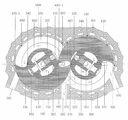
도 2은, A기통 회전피스톤 (130), B기통 회전피스톤 (140), 공기 압축기 A기통 회전피스톤 (270), B기통 회전피스톤 (280)을 제외한 본 발명기관 전체 평면 단면도.
도 3은, 본 발명 기관을 옆쪽에서 본 B기통 전체 단면도.
도 4는, 본 발명기관 냉각수 및, 냉각오일 순환도.
도 5는, A기통 회전피스톤 (130)과 B기통 회전피스톤 (140)의 구조 사시도.
도 6은, 본 발명기관을 정면에서 본 내부 단면도.
도 7은, 각 기통 고정자 내부 구조도 a는 평면도, b는 옆쪽에서 본 B기통 단면도, c는 고정자 저면도, d는 고정자를 왼쪽에서 본 도면, e는 고정자를 오른쪽에서 본 후면도.
도 8은 밸브 피스톤 (350) 구조도 a는 밸브피스톤 (350)을 위에서 내려다본 평면도, b는 저면도. c는 좌측면도, d는 전체단면도,
도 9는, 피스톤 왕복식기관, 본 발명 회전피스톤기관, 힘의 작용도.
도 10은, 우리나라 전통 생활 도구인 맷돌 본 발명 이론을 설명하기 위한 도면,
도 11, 11a, 11b, 11c, 11d, 11e, 11f, 11g, 11h, 11i 는 본, 발명기관의 행정순서 을 도시한 작용도.
도 12는, 본 발명기관 A기통 B기통에서 C기통 D기통으로 늘려 제작 할수 있다.
<도면의 주요부분에 대한 부호설명>
100 점화 뿌러그
110 A기통 연소실
120 B기통 연소실
130 A기통 회전피스톤
140 B기통 회전피스톤
150 하우징
160 하우징 부록
170 A기통 회전피스톤 (130) 타이밍기어
180 B기통 회전피스톤 (140) 타이밍기어
190 A기통 고정자
200 B기통 고정자
210 공기 압축기 공기 흡입구
220 압축 공기 토출구
220-1 앞축력이 있는 공기 공급구
230 캠샤후트 실, 엔진오일 저장실
240 하우징 오른쪽 커버
250 하우징부록 왼쪽 커버
260 공기 압축기
270 공기 압축기 A기통 회전피스톤
280 공기 압축기 B기통 회전피스톤
290 고정자 베어링
300 회전피스톤 축 1번 베어링
310 회전피스톤 축 3번 베어링
320 연소실 연료 공급 차단 발브
330 연소실 개패밸브 스프링
340 밸브실린더
350 밸브피스톤,
360 캠 샤후트 축
370 정비 과정에서 손이 들어갈 수 있는 공간
380 압축력이 있는 연료혼합기체 저장실
390 오일 누출 방지 씰
390-1 냉각수 누출 방지 씰
400 카스기드
410 1번 베어링 윤활유 공급구
420 1번 베어링 윤활유 배출구
430 회전피스톤 축 냉각수 구멍 밀폐용 캡
440 냉각수 공급 쪽과 토출구 칸막이 철판
450 회전피스톤 축 칸막이 철판 440이 끼워지는 ㄷ자 홈
460 회전피스톤 130의 안쪽 곡선
470 회전피스톤 130의 열처리가 된 꼭짓점
470-1 회전피스톤 130의 꼭짓점으로 열처리가 안 되어있는 꼭짓점.
480 회전피스톤 140의 안쪽 곡선
490 회전피스톤 140의 열처리가 된 꼭짓점
490-1 회전피스톤 140 꼭짓점으로 열처리가 안 되어있는 꼭짓점.
500 에어크리너
500-1 에어크리너 2차쪽
510 공기 압력 조정밸브
520 공기압 감지쎈서
530 온도 감지 쎈서
540 공기 냉각기
550 분사실
560 연료 혼합기체 역류 차단 발브
570 하우징부록, 하우징커버 연소가스 배기 홈
580 A기통 연소가스 배기구
590 중간 연소가스 배기구
600 B기통 연소가스 배기 구
610 공기 압축기 회전피스톤 구조도
620 하우징 부록 냉각수 순환구
620-1 하우징부록 냉각수 배출구
630 타이밍기어 윤활유 공급구
630-1 윤활유 교환구
640 고정자가 들어갈 회전피스톤 공간
650 은 회전피스톤 왼쪽 축 역활을 하며 회전피스톤 밸런스휠 2가지 작용을 한다.
660 회전피스톤 오른쪽 축
660-1 회전피스톤 왼쪽 축
670 회전피스톤 타이밍기어 고정너트
680 타이밍 기어 커버
690 저압노즐
700 고정자 밸브실린더 압축공기 공급구
710 고정자 냉각수 홈
720 공기 압축기 A기통 하우징
730 공기 압축기 B기통 하우징
740 밸브피스톤 압축 공기 공급구
750 분사실 (550)에서 공급되는 고정자 연료혼합기체 공급구
760 회전피스톤 왼쪽 축 메탈 베어링
770 밸브 씨드
780 고정자 메탈 베어링 윤활유 공급구
790 고정자 메탈 베어링 윤활유 배출구
800 밸브피스톤 저면도 나란이꼴 홈
810 회전피스톤 냉각수가 들어있는 몸통
820 회전피스톤 (130)과 회전피스톤 (140) 연소가스 배기 홈
830 고정자 오일 링, 연소실에서 발생된 폭발 압이 고정자 (230)안쪽으로 새어 들어가는 것을 방지하는 작용과 엔진오일 누출 방지링
840 하우징 부록 오일링
850 고정자 캠샤후트 실 캡
860 밸브 가이드
870 밸브 스템
880 밸브피스톤 리터이너 로크키
890 밸브피스톤, 밸브시린더 간극 윤활유 공급구
890-1 밸브가이드, 밸브스템 간극 윤활유 공급구
900 회전피스톤 냉각수 공급구
900-1 회전피스톤 냉각수 배출구
920 회전피스톤 냉각수 홈
930 하우징 150 미세 간극 조정핀
940 고정자 미세간극 조정핀
950 볼트구멍
960 스라스토 베어링 역활을 하는 메탈베어링
970 회전피스톤 배런스 휠 (650) 냉각수 순환구
980 냉각수 공급 4각 원형 홈
980-1 냉각수 배출 4각 원형 홈
990 회전피스톤 축 냉각수 공급구
990-1 회전피스톤 축 냉각수 배출구
1.000 캠샤후트실 (230)내 압축력이 있는 공기가 채워질 수 없도록 공기가 빠져나가는 숨통 공기구멍.
1.100 밸브피스톤 (350)이 밸브시린더 (340)내를 아래위로 왕복 작용과정에서 윤활유가 밸브피스톤 (350)안으로 들어가 누적 될 수가 있으므로 들어간 오일이 바늘구멍 (1.100)을 통해 캠샤후트실 (230)안으로 떨어지고 압축력이 있는 공기는 숨통 구명 1.000을 통해 빠져나가게 된다.
1.200 각 기통 고정자 냉각수 공급구
1.300 냉각 시킨 더워진 물 토출구
1.400 회전피스톤 축 냉각수 공급 순환구
1.400-1 회전피스톤 축 냉각수 배출 순환구
1500 회전피스톤 오일 누출, 폭발압 누출 방지링
1600 고정자 좌측 냉각수 홈과 우측 냉각수 홈으로 연결되어 있는 피이프관
1700 고정자 와 회전피스톤 간극 윤활유 공급구
1800 미니 오일펌프, 회전피스톤 축이 회전하게되면 캠샤후트 홈 (230)에 채워져있는 오일이 (1800) 홈으타고 올려져 (890)과 (890-1) 공급, 채워진 오일은 베어링 (290)사이로 흘러내리게 된다.
1801 회전피스톤 축 타이밍기어
1802 캠샤후트 타이밍 기어
1803 B기통 140과 C기통 140-1 연결 부품
1804 점화 프러그 고압 전선이 끼워지는 구멍
1805 윤활유 누출 방지용 캡
1806 캠샤후트 (360), 미니오일펌프 (1800), 고정자 베어링 (290)이 장치되는 축1 is a view showing the process of generating power from the air intake of the invention engine.
1a is a structural diagram of an air compressor rotating piston;
2 is a cross-sectional plan view of the entire engine of the present invention except for the A
Fig. 3 is an overall cross-sectional view of cylinder B when the engine of the present invention is viewed from the side.
4 is a cooling water and cooling oil circulation diagram of the engine of the present invention.
5 is a structural perspective view of the A
6 is an internal cross-sectional view of the engine of the present invention viewed from the front.
7 is a structural diagram of each cylinder stator, a is a plan view, b is a cross-sectional view of a cylinder B seen from the side, c is a stator bottom view, d is a view of the stator from the left, and e is a rear view of the stator seen from the right.
8 is a structural diagram of the
Figure 9 is a piston reciprocating engine, the present invention rotary piston engine, the action of the force.
Figure 10 is a view for explaining the invention theory of the millstone, a traditional living tool in Korea,
11, 11a, 11b, 11c, 11d, 11e, 11f, 11g, 11h, and 11i are operational diagrams showing the administrative sequence of the invention organ;
12, it can be produced by extending from the A-cylinder B-cylinder to the C-cylinder D-cylinder of the present invention.
<Explanation of symbols for main parts of the drawing>
100 spark plug
110 A cylinder combustion chamber
120 B-cylinder combustion chamber
130 A cylinder rotary piston
140 B cylinder rotary piston
150 housing
160 housing appendix
170 A cylinder rotary piston (130) timing gear
180 B cylinder rotary piston (140) timing gear
190 A cylinder stator
200 B cylinder stator
210 air compressor air intake
220 compressed air outlet
220-1 front axle air inlet
230 Camshaft seal, engine oil storage room
240 housing right cover
250 Housing Appendix Left Cover
260 air compressor
270 Air Compressor A Cylinder Rotary Piston
280 Air Compressor B Cylinder Rotary Piston
290 stator bearing
300 Rotary Piston Shaft No. 1 Bearing
310 Rotary Piston Shaft No. 3 Bearing
320 Combustion chamber fuel supply shutoff valve
330 Combustion chamber opening/closing valve spring
340 valve cylinder
350 valve piston,
360 cam shaft axis
370 Hand-accessible during maintenance
380 Compressible fuel mixture storage room
390 Oil Leakproof Seal
390-1 Coolant Leakage Seal
400 Kasgid
410 No. 1 bearing lubricant supply port
420 bearing lubricating oil outlet
430 rotary piston shaft coolant hole sealing cap
440 Cooling water supply side and outlet partition steel plate
U-shaped groove into which the 450 rotary piston shaft
460 inner curve of
Heat-treated vertex of 470
470-1 The vertex of the
Inside curve of 480
Heat-treated vertex of 490
490-1 The vertex of the
500 air cleaner
500-1 Air cleaner 2nd side
510 air pressure regulating valve
520 air pressure sensor
530 temperature sensor
540 air cooler
550 jet chamber
560 fuel mixture gas backflow shutoff valve
570 Housing Annex, Housing Cover Flue Gas Exhaust Groove
580 A cylinder flue gas exhaust port
590 Intermediate flue gas exhaust
600 B cylinder flue gas exhaust port
610 Air Compressor Rotary Piston Structure Diagram
620 Housing Appendix Coolant Circulation Hole
620-1 Housing Annex Coolant Outlet
630 timing gear lubricant supply port
630-1 Lubricant change port
Rotating piston space for 640 stator
650 acts as the left axis of the rotary piston and has two functions of the rotary piston balance wheel.
660 Rotating Piston Right Shaft
660-1 Rotating Piston Left Shaft
670 Rotating Piston Timing Gear Fixing Nut
680 timing gear cover
690 low pressure nozzle
700 stator valve cylinder compressed air inlet
710 stator coolant groove
720 air compressor A cylinder housing
730 air compressor B cylinder housing
740 valve piston compressed air inlet
750 Stator fuel mixture gas supply port supplied from injection chamber (550)
760 Rotating Piston Left Shaft Metal Bearing
770 valve seed
780 Stator Metal Bearing Lubricant Inlet
790 Stator Metal Bearing Lubricant Drain
800 valve piston bottom view parallel groove
Body containing 810 rotating piston coolant
820 rotary piston (130) and rotary piston (140) flue gas exhaust groove
830 stator oil ring, an action to prevent the explosion pressure generated in the combustion chamber from leaking into the stator (230) and an engine oil leak prevention ring
840 housing appendix oil ring
850 Stator Camshaft Seal Cap
860 valve guide
870 valve stem
880 Valve Piston Reiner Locky
890 Valve piston, valve cylinder gap Lubricant supply port
890-1 Valve guide, valve stem gap Lubricant supply port
900 rotary piston coolant inlet
900-1 rotary piston coolant outlet
920 rotary piston coolant groove
930
940 Stator micro-gap adjustment pin
950 bolt hole
960 Metal bearings that act as Thrusto bearings
970 Rotary Piston Balance Wheel (650) Coolant Circulation
980 Cooling water supply square round groove
980-1 Coolant Drain Square Circular Groove
990 rotary piston shaft coolant supply port
990-1 rotary piston shaft coolant outlet
1.000 Breathing hole through which air escapes so that compressed air in the
1.100 In the process of reciprocating the valve piston (350) up and down in the valve cylinder (340), lubricating oil may enter the valve piston (350) and accumulate, so the oil enters the camshaft seal (230) through the needle hole (1.100). Falling in, the compressed air exits through the 1.000 trachea.
1.200 each cylinder stator coolant inlet
1.300 Cooled hot water outlet
1.400 rotary piston shaft coolant supply circulation port
1.400-1 rotary piston shaft coolant discharge circulation port
1500 rotary piston oil leak, explosion pressure leak prevention ring
1600 Pipe pipe connected to the left cooling water groove and the right cooling water groove in the stator
1700 stator and rotary piston clearance lubrication inlet
When the 1800 mini oil pump, rotating piston shaft rotates, the oil filled in the camshaft groove (230) rises up the (1800) groove and supplies (890) and (890-1), and the filled oil flows between the bearing (290). will come down
1801 rotary piston shaft timing gear
1802 camshaft timing gear
1803 B-
1804 spark plug high voltage wire hole
1805 Lubricating Oil Leakage Cap
1806 Camshaft (360), mini oil pump (1800), shaft on which the stator bearing (290) is mounted
도1 에어크리너 (500)에서 정화된 공기는 공기 압축기 (260)에서 압축, 압축된 공기는 공기 냉각기 (540)을 통해 공기압 역류방지 밸브 (560)을 거처 연료 분사실 (550)까지 공급한다. 이 과정에서 기관이 필요로 하는 공기압으로 각 기통 연소실에 공급하기 위해 공기압 감지 쎈서 (520)에서 기관이 필요로 하는 공기압으로 감지, 감지신호를 공기압 조정기 (510) 으로 보내 기관이 필요로 하는 공기압으로 변환시켜 공기 냉각기 (540)을 통해 공기압 역류방지기 (560)을 거처 연료 분사실 (550)까지 공급한다. 또한 공기 압축 과정에서 발생된 고열의 공기를 기관이 필요로 하는 온도로 연료 분사실 (550)까지 공급하기 위해 공기온도 감지 쎈서 (530)에서 기관이 필요로 하는 공기온도로 감지, 기관이 필요로 하는 감지 신호를 공기 냉각기 (540)으로 보내 기관이 필요로 하는 공기온도로 변환시켜, 공기압 역류방지 밸브 (560)를 통해 분사실 (550)까지 공급한다. 기관이 필요로 하는 공기압과 기관이 필요로 하는 공기온도 속에 기관이 필요로 하는 공기압과 동일한 압력으로 분사노즐 (690) 으로 간접분사 연료 혼합기체 공급로 (750)을 통해 도3의 고정자 연료혼합 기체 공급구 (750)을 거처 연료혼합기체 저장실 (380)까지 공급한다. 이러한 냉각장치를 해야만 하는 이유는 발화점이 낟은 수소가스를 연료로 사용하기 위해서이다.1, the air purified in the
다른 방법으로는 압축기에서 발생된 고열의 공기를 직접 연소실 (120)에 공급 디젤기관 분사방식 해당 연료를 직접분사 폭발력을 발생시키는 방법도 있다. 본 발명 기관에서는 이방법이 안전하다. 도1의 (700)은 도3에서 고정자 (200)의 (700)과 연결한다.As another method, there is also a method of directly injecting the fuel of a diesel engine injection method by directly supplying high-temperature air generated by the compressor to the
도 1a는 공기 압축기 구조도. 도면의 (720)은 A기통 하우징, (730)은 B기통 하우징, (270)은 A기통 회전피스톤, (280)은 B기통 회전피스톤, (210)은 공기 흡입구, (220)은 압축공기 토출구, (610)은 피스톤 구조도1A is a structural diagram of an air compressor; In the drawing,
도 2은 A기통 회전피스톤 (130), B기통 회전피스톤 (140), 공기 압축기 회전피스톤 (270)과 회전피스톤 (280)을 제외한 전체 평면 단면도이다. A기통 B기통으로 구분 되어있는 하우징부록 (160)에 도5의 A기통 회전피스톤 (130)과 B기통 회전피스톤 (140)을 넣어 회전피스톤 오른쪽 (660)축에는 1번 베어링 (300)을 압입 장치하여 A기통 회전피스톤 (130)을 A기통 하우징 (150) 안으로 넣고, B기통 회전피스톤 (140)은 B기통 하우징 (150)안에 넣어 각 기통 회전피스톤 왼쪽 축 (660-1)에는 2번 메탈베어링 (760)으로 장치하여 하우징커버 (250)을 하우징 부록 (160)에 결합 하고, 다음으로 오른쪽 A기통 회전피스톤 (130)축에는 공기 압축기 회전피스톤 (270)을, B기통 회전피스톤 (140) 축에는 공기 압축기 회전피스톤 (280)을 각각 압입 장치하여 하우징부록 커버 (240)으로 하우징 부록 (160)에 결합하고, A기통 회전피스톤 (130) 축에는 타이밍기어 (170)을 B기통 회전피스톤 (140) 축에는 타이밍기어 (180)을 압입 장치하고 이어 고정너트 (670)으로 조여 고정시키고, 각 기통 회전피스톤 축에는 3번 베어링 (310)으로 압입장치, 이어서 오일 누출 방지 씰 (390)과 냉각수 누출 방지 씰 (390-1)으로 장치되어있는 타이밍기어커버 (680)을 하우징커버 (240)에 결합한다. (도면 7 참조) 도면 7 에서와 같은 구조로 되어있는 고정자 (190)과 (200)을 (도5, 640참조) 하우징 부록 (160)에 장치되어있는 A기통 회전피스톤 (130)의 고정자 투입구 (640) 안으로 고정자 (190)을 넣고, B기통 회전피스톤 (640)에 B기통 고정자 (200)을 넣어 하우징커버 (250)에 결합한다. 결합 또는 조립 과정에서 (도 11a, 참조) 에서와 같이 조립해야 된다. 또 다른 조립 방법으로는 도11f에서와 같이 조립해도 된다. A기통 회전피스톤 (130)은 고정자 (190)을 중심으로 반시계방향으로 회전을 하고, B기통 회전피스톤 (140)은 고정자 (200)을 중심으로 시계방향으로 회전하며 동력을 발생시키는 회전피스톤 내연기관이다.2 is an overall plan cross-sectional view except for the A
도면 3은 도2의 B기통을 옆쪽에서 본, 전체 단면도이다. B기통 하우징부록 (160)에는 냉각수 순환구 (620)과 공기 압축기 회전피스톤 (280)이 장치되는 하우징 (720), 공기흡입구 (210), 압축공기 토출구 (220), 회전피스톤 축 1번 베어링 (300)이 장치되는 홈, 폭발 압 누출 방지용 카스키트 (400)이 끼워지는 홈, 오일링 (840)을 끼워 장치하는 2개의 원형 홈, 구조로 되어 있는 하우징부록 (160) 안으로 하우징 부록 오일링 (840)을 끼워 장치하고, 이어서 회전피스톤 (660)축에 1번 베어링 (300)으로 압입장치하여, 도5의 B기통 회전피스톤 (140)을 도6 에서와 같이 B기통 하우징 (150) 안으로 넣고, 왼쪽 회전피스톤 (660-1)축에는 2번 메탈베어링 (760)으로 압입 장치하고 압축 누설 방지용 카스킷트 (400)으로 하우징 부록 (160)에 장치하여 하우징부록 커버 (250)으로 하우징 부록 (160)에 결합하고. 다음으로 B기통 회전피스톤 (140) 축에는 공기 압축기 B기통 회전피스톤 (280)을 압입 장치하여 하우징 부록 커버 (240)으로 하우징부록 (160)에 결합하고, 이어 회전피스톤 (140)축에는 타이밍기여 (180)을 압입 장치하여 타이밍기어 고정너트 (670)으로 조여 고정시키고, 회전피스톤 축 (660)에는 3번 베어링 (310)으로 압입장치, 이어서 오일 누출 방지 씰 (390)과 냉각수 누출 방지용 씰(390-1)이 장치되어있는 타이밍기어 커버 (680)으로 하우징부록커버 (240)에 결합한다.3 is an overall cross-sectional view of the cylinder B of FIG. 2 viewed from the side. In the B
별도의 B기통 고정자 (200)에는 점화푸러그 (100), 연소실 (120), 밸브씨드 링 (770), 압축공기 공급구 (700) 연료혼합기체 공급구 (750), 연료혼합 기체 저장실 (380), 밸브가이드 (860), 밸브시린더 (340), 연소실 개패밸브 (320), 밸브피스톤 (350), (도8, 350, 740, 참조) 밸브피스톤 압축공기 공급구 (740), 밸브스프링 (330), 캠샤후트 홈 (230), 캠샤후트 (360), 고정자 오일링 (830), (도6, 710, 참조) 냉각수 순환구 (710), 캠샤후트실 (230)내 압축력이 있는 공기가 빠져 나갈 수 있는 공기 숨통구멍 (1000), 정비과정에서 손이 들어갈 수 있는 공간 (370), 고정자 베어링 (290), 미니오일펌프 (1800) 부품투입구 캡 (850), 구조로 되어있는 고정자 (200)을 회전피스톤 (140) 고정자 투입구 (640)안으로 넣는다. (도5, 640 참조) 넣는 과정에서 중요시 되는 것은 상기의 부품 조립 과정이다. B기통 고정자 (200)의 연소실 (120)에 밸브씨드링 (770)을 압입 장치하고, 이어서 밸브가이드 (860)을 압입 장치하여, B기통 연소실 (120) 개폐 밸브 (320)의 밸브스템 (870)을 밸브가이드 (860) 구멍에 밸브스템 (870)을 위에서 아래로 내려 꼽고. (도8, 860, 870참조) 꼽은 다음 캠샤후트 실 (230) 캡 (850)을 열고, (도8, 330, 340, 350참조) 밸브스프링 (330)을 밸브시린더 (340) 안에 넣고, 이어서 밸브피스톤 (350)을 밸브시린더 실 (340) 안으로 넣는다. 넣는 과정에서 (도8, 740참조) 밸브피스톤 (350)의 압축공기 공급구 구멍 (740)이 고정자 (200)의 압축공기 공급구 (700) 구멍과 일치 되도록 조립해야 된다. 밸브피스톤 (350)이 좌우로 돌아 갈수 있으므로 캠샤후트 (360) 캠이 밸브피스톤 (350)의 양쪽 레일 (800) 홈을타고 회전할수있도록 도면에서와 같이 조립하고, 다음 밸브피스톤 (350)을 최대한 위쪽으로 올린 다음 (도8, 880참조) 밸브스탬 (870)에 리터이너로크키 (880)으로 조립하여 밸브피스톤 (350)을 아래로 내려놓는다. 결합이 끝난 상태에서. 고정자 (200)에는 스라스토베어링 역활을 하는 오일레스베어링 (960)과 고정자 오일링 (830)을 끼워 장치하여 회전피스톤 (140)의 고정자 투입구 (640) 안으로 (도5, 640참조) 고정자 (200)을 밀어 넣는다. 밀어 넣어 하우징커버 (250)에 결합한다. 이어서 고정자 (200)의 냉각수 공급구 (1200)을 냉각수 냉각기 OUT 쪽으로 연결하고, 냉각수 토출구 (1300)은 냉각수 냉각기 (IN) 쪽으로 연결 하고 연료혼합기체 공급구 (750)을 도1의 (750)과 연결하고, 또한 압축력이있는 공기 공급구 (700)을 도1의 (700)과 연결한다. 도1의 (700)을 연결하는 이유는 압축력이 있는 연료혼합기체를 연료혼합기체 저장실 (380)에만 넣어주게 되면 연소실 (120) 개폐밸브 (320)이 압축력이 있는 연료혼합기체 압력에 의해 비정상적으로 연소실 (120) 개패밸브 (320)이 위쪽으로 열려 연소실 (120) 연료혼합기체 공급 차단 작용이 비정상적으로 이루어지므로 기관 운전을 할 수 없기 때문이다. 그러나 도1의 압축기 (260)에서 공급되는 압축력이 있는 공기를 압축공기 공급구 (700)거쳐 밸브피스톤 (350)의 압축력이 있는 공기 공급구 (740)을 통해 밸브시린더 (340) 안에 넣어주게 되면 밸브피스톤 (350)을 캠축 (360)이 있는 아래쪽으로 내려 미는 작용을 하므로 연소실 (120) 개패발브 (320)은 밸브스프링 (330) 인장력으로만 B기통 연소실 (120) 개폐작용을 정상적으로 할 수 있다. 밸브시린더 (340)안에 공급되는 압축력이 있는 공기는 순수 압축력이 있는 공기다. 도면의 (630)은 타이밍기어 윤활유 공급구 (630-1)은 기어 윤활유 교환구 앞쪽에서 부품 조립 과정이 B기통에서 끝나는 동시에 A기통 고정자 (190)에서도 이루어져 도11에서 ~ 도11i 까지 이러한 과정을 거처 회전 동력을 발생시킨다.Separate B-
도 4는 기관 냉각수 순환 방식과 엔진부품 윤활유 공급 방식에 관한 것으로 (도면4a 620참조) 하우징부럭 (160) 냉각수 공급구 (620)으로 넣어진 냉각수는 화살표 방향으로 순환 더워진 물은 배출구 (620-1)쪽으로 배출된다. 배출된 냉각수는 다시 냉각시켜 냉각수 공급구 (620) 쪽으로 재공급된다. 냉각수 순환 방식은 A기통 B기통 동일하다.4 is related to the engine coolant circulation method and the engine parts lubricant supply method (refer to FIG. 4a 620). The cooling water put into the
도면의 a, b는 회전피스톤 냉각 방식으로 a, b는 회전피스톤 축 (660)과 타이밍기어 커버 (680) 단면도이다. 도면의 (900)쪽으로 넣어진 냉각수는 타이밍기어커버 4각 원형 홈 (980)을 타고 돌아 회전피스톤 축 (990)쪽으로 들어가 (1400-1) 반원 홈을 타고 화살표 방향으로 순환 회전피스톤 냉각수 홈 (920)을 거처 위쪽으로 돌아 반원 홈 (1400) 순환구를 거처 화살표 방향으로 순환 도b 에서 회전피스톤 축 (990-1) 으로 들어가 타이밍커버 (980-1) 원형 4각 홈을 타고 돌아 냉각수 배출구 (900-1) 쪽으로 배출된다. 배출된 냉각수는 다시 냉각기에서 냉각시켜 냉각수 공급구 (900)쪽으로 넣어져 재순환된다. 부품 결합 과정에서 편리대로 역으로 배출구 (900-1)쪽으로 냉각된 냉각수를 넣어주어도 되고 공급구 (900)쪽으로 더워진 물을 배출시켜도 된다. A기통 B기통 냉각수 순환 방식은 동일하다.A and b of the drawing are cross-sectional views of the
다음으로 고정자 냉각방식이다. (도면7, 1200, 1300참조) 냉각수 공급구(1200)으로 넣어진 왼쪽 냉각수는 (도6, 1600참조) 파이프 관을 통헤 오른쪽 냉각수 홈으로 옮겨져 옮겨진 냉각수는 화살표 방향으로 순환 더워진 물은 배출구 (1300)으로 배출된다. 배출된 물은 다시 냉각시켜 냉각수 공급구 (1200)쪽으로 넣어진다. A기통, B기통 고정자 냉각수 순환방식은 동일하다.Next is the stator cooling method. (See Figs. 7, 1200, 1300) The left cooling water put into the cooling water supply port 1200 (see Figs. 6 and 1600) is moved to the right cooling water groove through the pipe pipe, and the transferred cooling water is circulated in the direction of the arrow. 1300) is released. The discharged water is cooled again and put into the cooling
도면의 (210)은 공기 흡입구, (220)은 압축된 공기압 토출구, (410)은 회전피스톤 바란스 휠과 하우징부럭 간극 윤활유 공급구, (420)은 오일 배출구, (780)은 회전피스톤 2번 메탈베어링 오일 공급구, (790)은 메탈베어링 오일 배출구, (1700)은 고정자 와 회전피스톤 간극 윤활유 공급구, (890)은 밸브시린더 (340)과 밸브피스톤 (350), 간극 윤활유 공급구, (890-1)은 밸브스템과 밸브가이드 간극 윤활유 공급구, (1500)은 회전피스톤 폭발압 누출 방지 및 오일 누출 방지링, (1600)은 고정자 냉각수 왼쪽 홈에서 오른 쪽 홈으로 옮기는 파이프관, (1700)은 연소실 (120)에서 발생된 폭발압이 캠샤후트 홈 (230) 있는 쪽으로 누출을 방지하기 위한 압축 누설 및 오일 누출 방지, 고정와 회전피스톤 간극 윤활유 공급구, 미니오일펌프 (1800)은 캠샤후트 (230) 홈에 채워져 있는 윤활유를 미니 오일펌프로 밀어 올려 (890)과 (890-1) 빈 공간에 채워지게되면 자동으로 (890)과 (890-1)에 공급 윤활 작용을 하게 된다. (400)은 폭발압 누출 방지용 가스깃드. (1.000)은 밸브시린더 (340)내의 압죽력이 있는 공기와 연소실 (120)에서 발생된 폭발 압이 누출 캠샤후트실 (230)에 채워지게 되면 밸브피스톤 (350)이 정상적인 작용을 할 수 없으므로 압축력이 있는 공기가 공기 숨통구멍 (1.000)을 통해 빠져 나갈 수 있는 숨통 구멍.
도 5는 A기통, B기통 회전피스톤 구조도, (640)은 각 기통 고정자 (190)과 고정자 (200)이 (640) 안으로 넣어져 장치되는 공간이 되고. (460)은 A기통 회전피스톤 안쪽 곡선, (470)은 바깥 꼭짓점, (810) 냉각수가 들어있는 몸통, (360)은 연소실 개폐발브 (320)을 작동시키는 캠축, (650)은 밸런스 휠, (660-1)은 회전피스톤 왼쪽 축, 미니오일펌프 (1800)은 밸브시린더 (340)과 밸브피스톤 (350), 밸브스템 (870) 밸브가이드 (860) 간극 윤활유 공급을 하기위한 오일펌프로 회전피스톤 축이 회전을 하게 되면 캠샤후트홈 (230에 채워져있는 윤활오일이 (1800) 홈을타고 올려져 (890)과 (890-1)이 있는 공간 홈에 채워져 자동으로 (890)과 (890-1)에 윤활유 작용을한다. 나머지 오일은 고정자 베어링 (290) 윤활 작용을 하며 (230)쪽으로 흐러내린다. (820)은 (도11e, 820참조) A기통 회전피스톤 (130)이 반시계방향으로 회전을 하고. B기통 회전피스톤 (140)이 시계방향으로 회전을 하는 과정에서 B기통 회전피스톤 (140)의 꼭짓점 (490-1)이 A기통 회전피스톤 (130)의 꼭짓점 (470)을 타고 안쪽 곡선 (460) 쪽으로 회전을 하게 된다. 이 과정에서 회전피스톤 (130)과 회전피스톤 (140) 꼭짓점 사이에서는 회전력에 방해가 되는, 압축력이 발생된다. 압축력이 발생 될 수 있는 연소가스가 A기통 회전피스톤 (130)의 연소가스 배기홈 (820)을 거처 하우징부록 (160)과 하우징 부록커버 (250)의 깊이가 있는 배기 홈 (570)을 통해 연소가스 배기구 (590) 을 통해 빠져나간다. A기통 회전피스톤 (130)과 B기통 회전피스톤 (140)은 같은 구조로 되어 있다. 단 연소가스 배기 홈 (820) 방향이 다르다.5 is a cylinder A and B cylinder rotary piston structure diagram, 640 is a space in which each
도 6은 본 발명 기관을 정면에서 본 내부 단면도이다. 왼쪽이 A기통, 오른쪽이 B기통이다. 하우징부록 (160) 안으로 A기통 회전피스톤 (130)과 B기통 회전피스톤 (140)이 넣어져 A기통 회전피스톤 (130)은 A기통 고정자 (190)을 중심으로 반시계 방향으로 회전하고, B기통 회전피스톤 (140)은 B기통 고정자 (200)을 중심으로 시계방형으로 회전을 한다. (150)은 A기통, B기통 하우징, 도면의 (380)은 도1, 분사실 (550)에서 공급되는 압축력이 있는 연료혼합기체 저장실, (320)은 연소실 (110)과 (120) 개패밸브, (580), (590), (600)은 연소가스 배기구, (360)은 캠샤후트 홈, (330)은 연소실 개패밸브 스프링, (820)은 (도11, B기통 참조) 회전피스톤 (130)이 반시계방형으로 회전을 하고 회전피스톤 (140)이 시계방향으로 회전을 하게 되면 회전력에 방해가 되는 연소가스가 배기구 (820)을 통해 깊이가 있는 하우징부록 배기 홈 (570)과 하우징부록 커버 (250)의 (570) 통해 중간 연소가스 배기구 (590)으로 배기된다. (620) 하우징 부록 냉각수 순환구, (710) 고정자 냉각수 순환구, (930)은 하우징 (150) 내벽과 회전피스톤 외벽사이 압축 누설을 막는 간극 수치에 따라 간극에 맞는 끼워지는 길이가 있는 미세간극 핀, (940))은 회전피스톤 내벽과 고정자 외벽사이 폭발압 누설을 막는 길이가 긴 미세간극 핀, (650)은 배런스 휠, (460)은 A기통 회전피스톤 안쪽 곡선, (470)은 A기통 회전피스톤 (140) 바깥 꼭짓점, (480)은 B기통 회전피스톤 (140) 안쪽 곡선 (490)은 B기통 회전피스톤 (140) 바깥 꼭짓점, (470-1)과 (490-1)은 열처리가 안 된 꼭짓점 (230)은 캡샤후트 오일 저장실, (850)은 캠사후트실 캡, (340)은 밸브시린더, (350) 밸브피스톤 (도8, 350 참조) (950)은 볼트구멍.(1600)은 냉각수 순환관.6 is an internal cross-sectional view of the engine of the present invention viewed from the front. A cylinder is on the left, and a cylinder B is on the right. A
도7은 A기통 고정자 (190)과 B기통 고정자 (200) 내부구조도. a는 고정자를 위에서 아래로 내려다 본 평면도, (100)은 점화푸러그, (320)은 연소실 연료혼합기체 공급 차단 밸브, (120)은 B기통 연소실, b는 고정자를 옆쪽에서 본 내부 단면도, (890)은 밸브시린더 (340)과 밸브피스톤 (350) 간극 윤활유 공급구, (890-1) 밸브스템 과 밸브가이드 (860) 윤활유 공급구, (1000)은 밸브시린더 내벽과 밸브피스톤 외벽 사이로 누출되는 공기압이 캠사후트실 (230)에 채워지게 되면, 또는 연소실에서 발생된 압축력이 있는 폭발 압이 누출되어 캠샤후트실 (230)에 채워지게 되면 밸브피스톤이 정상적으로 작용을 할 수 없게 되므로 압축력이 있는 연소가스 또는 압축력이 있는 공기가 숨통구명, (1000)을 통해 빠져나가고 누출된 오일은 캠샤후트 홈(230)안에 떨어진다. c는 고정자 저면도, (850)은 캠샤후트 홈 밀패용 캡, d는 좌측에서 본 면도 (100)은 점화푸러그 (1200)은 고정자 냉각수 공급구, (1300)은 고정자 더워진 물 토출구, (700)은 압축공기 공급구, (1000)은 압축력이 있는 공기압 토출구 e는 고정자를 우측에서 본, 도면 (1700)은 고정자와 회전피스톤 간극 윤활유 공급구. (830)은 연소실에서 발생된 폭발압이 누출되어 캠 샤후트실 안으로 들어가는 것을 장지하는 오릴링7 is an
도8은 밸브피스톤 구조도, a는 밸브피스톤을 위에서 내려다 본 평면도, b는 밸브피스톤 저면도, 밸브피스톤 (350)이 밸브시린더 내에서 상하 왕복 과정에서 좌우로 회전할 수 없도록 (도3, 360참조)캠축의 캠이 나란이 꼴 돌출 부분 (800)안의 홈을타고 캠축이 회전 할 수 있도록 나 있는 홈 c는 밸브피스톤 좌측면도 (740)은 도 1 (700)에서 공급되는 압축력이 있는 공기가 밸브피스톤 (740)을 통해 밸브피스톤 (350) 안에 까지 공급된다. d는 밸브피스톤 (350) 내부 전체 단면도, (860) 밸브가이드, (330)은 밸브 스프링, (870)은 밸브스템, (880)은 리터이너 로크키, (350)은 밸브피스톤, (1100)은 밸브피스톤 (350)이 밸브시린더 (340)내를 아래 위로 왕복작용 과정에서 극소량의 윤활유가 밸브피스톤 (350)안에 들어가 누적 될 수 있으므로 들어간 윤활유가 고압의 공기압에 의해 밸브피스톤 (350)의 바늘구멍 (1100)을 통해 캠샤후트실 (230)에 떨어지게 되고 공기는 숨통 구멍 (1000)을 통해 빠져 나갈 수 있도록 아주 작은 바늘구멍, 바늘 구멍은 밸브피스톤 아래쪽에 뚫어주어야 된다. (1.100) 구멍을 크게 뚫어주어서는 안 된다. 이유로는 밸브시린더 (340)내 공기 압력이 떨어지게 되면 밸브피스톤 (350)이 정상적인 작용을 할 수 없기 때문이다.8 is a structure diagram of the valve piston, a is a plan view of the valve piston from above, b is a bottom view of the valve piston, so that the
도 9는 피스톤 왕복식 내연기관, 본 발명 회전피스톤 내연기관, 어느 기관에서 연료를 적게 드리고 강한 힘을 낼 수 있는지 기초 이론을 알아보기 위한 도면이다. 단기통 피스톤 왕복식 내연기관을 가지고, 폭발 압이 아닌 무계 (그램) 단위를 이용 피스톤을 내려 미는 힘으로 크랭크축 핀 각도별 실험을 하였다. (도면9, 1~18번 참조) 1번 크랭크 핀과, 커넥팅-로드, 피스톤이 1 직선, 수평 수직각 90도 각에서는 무한대의 압력으로 피스톤을 내려 밀어도 크랭크축 을 회전시킬 수 없다. 도9, 2번 크랭크 핀 각이 80도 각에서는 4.264의 많은 압력으로 피스톤을 내려 밀어야 크랭크축을 회전 시킬 수가 있었고, 도9, 3번 70도 각에서는 1.404 힘으로 피스톤을 내려 밀어야 크랭크축을 회전 시킬 수가 있었다. 도9, 4번 60도 각에서는 780 내려 미는 압력으로 크랭크축을 회전 시킬 수가 있었고, 5번에서는 4번에서보다 적은 572 압력으로, 6번은 5번에서보다 적은 468 힘으로, 7번은 6번에서보다 적은 416 힘으로, 8번은 7번에서보다 적은 364 여기에서 가장 적은 압력으로 크랭크축을 회전 시킬 수 있었다. 여기에서 이론이 본 발명 이론하고 같은 이론이다. 도면 11f B기통 연소실 (120) 하부는 연소실 개폐밸브 (320)에 의해 밀폐가 되는 동시에 폭발력이 발생 도 11f, 도11g 과정에서 완전연소, 도11g 후반에서 회전피스톤 (140)이 시계방향으로 회전 하게 되면 연소실 (120)이 열리는 동시에 도 11g와 도11h 과정에서 폭발 압은 회전피스톤 (130)을 등지고 피스톤왕복식 기관에서 헤드역활 회전피스톤 (140)을 시계방향으로 미러낸다. 여기에서 이론이 도면 9, 8번 20도 각에 해당되는 이론으로 (ㄱ)자 각 B기통 회전피스톤 (140) 중심축과, 회전피스톤 뒤쪽 정면을 미는 폭발압 방향각이 (ㄱ)자각 도9, 8번 20도 각에 해당되는 364 적은 압력으로 회전피스톤 축을 회전 시킬 수 있다. 도 9번 364 도10번 0도 각에서는 416, 0도 각을 지나서부터는 효율이 급격이 떨어져 11번 -10도 각에서는 468, 12번 -20도 각에서는 520, 13번 -30도 각에서는 676, 14번 -40도 각에서는 784, 15번 -50도각 1.040, 16번 -60도 각 1.560, 17번 -70도 각 2.964, 18번 -80도각 8.960 이상 피스톤을 내려 미는 압력으로 크랭크축을 최초 회전 시킬 수 있었다.Figure 9 is a piston reciprocating internal combustion engine, a rotary piston internal combustion engine of the present invention, which engine is a view for examining the basic theory of which engine can generate a strong force with less fuel. With a single-cylinder piston reciprocating internal combustion engine, an experiment was conducted for each crankshaft pin angle using the force that pushes the piston down using the unweighted (gram) unit, not the explosive pressure. (Refer to Figure 9, No. 1~18) The crankshaft cannot be rotated even if the piston is pushed down with infinite pressure when the crank pin No. 1, the connecting rod, and the piston are in a straight line and at an angle of 90 degrees horizontally and vertically. 9 and 2, at an angle of 80 degrees, the crankshaft had to be pushed down with a large pressure of 4.264 to rotate the crankshaft. there was. 9 and 4, it was possible to rotate the crankshaft with a pushing pressure of 780 at a 60 degree angle, in No. 5, less than in No. 4, with 572 pressure, in No. 6, with 468 force, less than in No. 5, and in No. 7, than in No. 6. With a small 416 force, the 8th was able to turn the crankshaft with the least pressure here, 364 less than the 7th. Here, the theory is the same as the theory of the present invention. 11f The lower part of the B
아래의 실험수치는 피스톤 왕복식기관 본 발명 회전피스톤 기관에서 회전축을 회전 시킬 수 있는 비교 수치다.The experimental values below are comparative values that can rotate the rotating shaft in the reciprocating piston engine of the present invention.
[보기][look]

상기의 A는 피스톤 왕복식 기관에서 크랭크축을 최초 회전 시킬 수 있는다, 다른 각도별 압력 이고, 상기의 B는 본 발명 이론에서 각도와는 무관한 어느 방향에서나 회전피스톤 축을 최초 회전시킬 수 있는 압력이다. 상기의 C는 피스톤 왕복식 기관에서 다, 다른 각도별 크랭크축을 최조 회전 시킬 수 있는 압력에서. 보기 도9, 2번 80도 각에서 42.64÷208=20.5 배 이상 본 발명 회전피스톤 기관에서보다. 20.5배 압축력이 더 있어야 크랭크축을 최초 회전 시킬 수 있다가 된다. 상기의 합계 25.116은 피스톤 왕복식 기관에서 다 다른 각도별 크랭크축을 최초 회전시키는 압력의 합산이고, 합계 3.536 수는 본 발명 회전피스톤 기관 각도와는 관계없이 회전피스톤 축을 최초 회전시킬 수 있는 압력의 합산이다. 25.116÷3.536=7.10 이다.A above is the pressure that can initially rotate the crankshaft in the piston reciprocating engine, and is the pressure for each angle, and B above is the pressure that can initially rotate the rotating piston shaft in any direction independent of the angle in the theory of the present invention. C above is for a piston reciprocating engine, at a pressure that can rotate the crankshaft at different angles at the earliest. Example Fig. 9, No. 2 at an angle of 80 degrees, 42.64 ÷ 208 = 20.5 times more than in the rotary piston engine of the present invention. 20.5 times more compression force is required to rotate the crankshaft for the first time. The above sum of 25.116 is the sum of the pressures that initially rotate the crankshaft for different angles in the piston reciprocating engine, and the total number of 3.536 is the sum of the pressures that can initially rotate the rotating piston shaft regardless of the angle of the rotating piston engine of the present invention. . 25.116÷3.536=7.10.
말을 다르게 하면 피스톤왕복식 기관에서 00이라는 연료로 1시간동안 1마력을 낼 수 있어 1 마력으로 갈수 있는 거리를 간다면 본 발명 회전피스톤 기관에서는 00이라는 같은 양의 연료로 7.1마력 이상 강한 에너지를 발생시킬 수가 있다. 7.1마력 중 1마력으로는 피스톤 왕복식 기관에서와 같이 1마력을 갈수 있는 거리를 가고, 남아도는 6.1 마력으로는 물을 전기분해 생산된 수소가스로 본 발명 기관을 연속 적으로 운전하는 식으로 하면 물만 넣으면 가는 자동차 이론이 된다.In other words, the reciprocating piston engine can produce 1 horsepower for 1 hour with fuel 00, so if you go the distance that can be traveled with 1 horsepower, the rotating piston engine of the present invention generates strong energy of more than 7.1 horsepower with the same amount of fuel 00 can do it With 1 horsepower out of 7.1 horsepower, it goes the distance that it can travel with 1 horsepower as in a piston reciprocating engine, and with the remaining 6.1 horsepower, the engine of the present invention is continuously operated with hydrogen gas produced by electrolysis of water. It becomes the theory of a car that goes by just adding water.
상기의 실험수치에서와 같이 피스톤왕복식 기관에서는 도9, 9번 -10도를 지나서부터는 효율이 급격히 떨어지고, 시린더 압력이 떨어져 강한 힘을 낼 수 없다. 강한 힘을 낼 수 없는 이유로는 크랭크축이 1회전하는 과정에서 시린더 상사점과 하사점에서 회전력에 방해가 되는 크랭크 장애현상이 2회 발생되기 때문이다 크랭크축이 1회전하는 과정에 고효율각 도9, 8번 20도 각이 1회 온다. 그러나 본 발명 회전피스톤기관 이론에서는 연소실에서 폭발력이 발생되면 처음부터 폭발압이 배기구를 통해 빠져 나갈 때 까지 끝까지 208 고효율 (ㄱ)자각을 계속 형성시키는 이론으로 208 적은 에너지로 회전피스톤 축을 회전시킬 수 있다.As in the above experimental values, in the reciprocating piston engine, the efficiency drops sharply after passing through FIGS. The reason that strong force cannot be generated is that during one revolution of the crankshaft, the crank failure phenomenon that interferes with the rotational force occurs twice at the top dead center and bottom dead center of the cylinder. 9, 8 and 20 degree angles come once. However, in the theory of the rotary piston engine of the present invention, when explosive force is generated in the combustion chamber, the 208 high-efficiency (a) perception continues to be formed from the beginning until the explosive pressure escapes through the exhaust port. .
도 10은 피스톤 왕복식 기관 이론과 본 발명 회전피스톤 기관이론을 쉽게 이해를 돕기위해 우리나라 전통 생활 도구인 맷돌을 가지고 설명한 도면이다. 도면의 (15)번은 피스톤 왕복식 기관 크랭크축 중심이 되고, 10번은 크랭크축 핀이 된다. 도면의 화살표는 커넥팅-로드 역할 을 한다. 맷돌의 중심축 (15)번과 맷돌의 손잡이 (10)번, 화살표가 1직선이 되도록 해놓은 상태에서 화살표 방향에서 맷돌 중심축 15번을 보고 10번을 화살표 방향으로 밀게 되면 아무리 힘을 많이 주어 밀어도 맷돌을 돌릴 수 없다. 여기에서 이론이 (도9, 1번 90도각 참조) 이다. 피스톤 왕복식기관 실린더 상사점에서 최고의 폭발력이 발생되지만 크랭크장애 현상으로 크랭크축을 회전시킬 수 없다. 맷돌을 회전시키기 위해서는 (도9, 2번 80도각 참조) 에서와 같이 크랭크축 핀각이 수직각에서 0.1도라도 수직각을 벋어나면서부터 회전력이 시작된다. 도9에서와 같이 각도별 실험을 해보면 잘 알 수 가 있다. 피스톤이 시린더 상사점에서 폭발력은 높지만 회전력에 있어서는 약에서부터 시작이 된다는 이론이다.10 is a view illustrating the piston reciprocating engine theory and the millstone, which is a traditional living tool in Korea, in order to easily understand the rotary piston engine theory of the present invention. Number (15) in the drawing is the center of the piston reciprocating engine crankshaft, and
도10, 2번 에서는 처음부터 맷돌의 손잡이 10번을 화살표 방향으로 원을 그리는 식으로 손잡이 10번 뒤쪽을 따라가며 밀기 때문에 처음부터 힘을 적게 들이고 맷돌을 회전 시킬 수 있다. 여기에서 이론이 본 발명이론으로 도11f 와 도11g 과정에서 완전 연소된 폭발 압은 11g 후반에서 회전피스톤 (140)이 시계방향으로 회전을 하게 되면 B기통 연소실 (120)이 열리는 동시에 도11g와 11h 과정에서 폭발 압은 회전피스톤 (130)을 등지고 회전피스톤 (140)을 시계방향으로 밀어낸다. 여기에서 이론이 본 발명 과 같다. B기통 회전피스톤 (140) 중심축과 회전피스톤 회전방향 뒤쪽 정면을 따라가며 미는 (ㄱ)자각 고효율각 본 발명 이론으로 하우징 (150)내에서 각도와는 관계없이 처음부터 적은 힘으로 맷돌을 회전 시킨다. 이, 이론이 도9, 8번 20도 각과 같은 이론이다.In Figures 10 and 2, the millstone can be rotated with little force from the beginning because the
도11, A기통, 회전피스톤 (130)이 반시계 방향으로 회전을 하고 B기통 회전피스톤 (140)이 시계방향으로 회전을 하는 과정에서 연소실 (110) 에는 캠축 (360)과 연소실 개패밸브 (320) 작용에 의해 연료혼합기체 저장실 (380)에 공급되어있던 압축력이 있는 연료혼합기체가 연소실 (110)에 공급된다.11, cylinder A, the
B기통, 전 과정에서 발생된 폭발 압은 회전피스톤 (130)을 등지고 회전피스톤 (140)을 시계방향으로 밀어낸다. 이 과정에서 A기톤 회전피스톤 (130)의 꼭짓점 (470-1)이 B기통 회전피스톤 (140)의 꼭지점 (490)을 타고 밀착 안쪽곡선 (480)쪽으로 회전을 한다. 이때 회전피스톤 (130)과 회전피스톤 (140) 꼭짓점 사이에서는 회전력에 방해가 되는 압축력이 발생된다. 압축력이 발생되는 연소가스가 회전피스톤 (140)의 배기 홈 (820)을 통해 하우징부록 (160)과 하우징커버 (250)에 설치되어 있는 안쪽으로는 깊이가 있는 홈 (570)을 통해 중간배기구 (590)쪽으로 빠져나간다.Cylinder B, the explosion pressure generated in the entire process pushes the
도 11a A기통 캠 축 (360) 작용에 의해 A기통 연소실 (110)은 밀폐가 되는 동시에 점화장치에 의해 폭발력이 발생 된다11a The cylinder
B기통 전 단계에서 발생된 폭발 압에 의해 회전피스톤 (140)을 시계방향으로 밀어내는 과정에 있다.B cylinder is in the process of pushing the
도 11b A기통 연소실 (110)에는 완전 연소된 폭발력이 발생된 상태에서 B기통 회전피스톤 (140)의 꼭지점 (490)이 A기통 회전피스톤 (130)의 안쪽 곡선 (460)을 따라 밀착 A기통 회전피스톤 (130) 밖깟 꼭짓점 (470-1)쪽으로 회전하게 된다. 11b 후반에서 회전피스톤 (130)에 의해 연소실 (110) 상부가 열리는 동시에 폭발 압은 A기통 하우징 (150) 내로 분출, 분출된 폭발 압 다음 단계에서 B기통 회전피스톤 (140)을 등지고 A기통 회전피스톤 (130)을 반시계방향으로 밀어 내게 된다.11b In the cylinder
B기통 전 단계에서 발생된 폭발압에 의해 회전피스톤 (140)을 시계방향으로 미러내는 과정에 있다.It is in the process of mirroring the
도 11c A기통 연소실 (110)에서 발생된 폭발 압은 회전피스톤 (140)을 등지고 회전피스톤 (130)을 반시계방향으로 밀어낸다.11c The explosion pressure generated in the A
B기통 회전피스톤 (140)에 의해 배기구 (600)이 열리면서 하우징 (150) 내의 폭발 압은 배기구 (600)을 통해 배기된다. 이때 압축력이 있는 폭발 압이 순간적으로 배기구 (600)을 통해 빼져나가는 과정에서 발생되는 배기가스 유출 관성에 의해 연소실 (120)이 있는 하우징 (150) 말단에서는 순간적으로 약간의 진공이 발생된다. 진공이 발생되는 동시에 다음 단계에서 회전피스톤 (140)이 시계방향으로 회전 연소실 (120) 상부는 회전피스톤 (140)에 의해 밀폐 된다.As the
도11d A기통 하우징 (150)내의 폭발 압은 A기통 회전피스톤 (130)을 반시계 방향으로 밀어낸다.11d The explosion pressure in the
B기통 회전피스톤 (140)이 시계방향으로 회전 캠축 (360)과 연소실 개폐밸브 (320) 작용에 의해 연소실 (120) 하부가 열리고 연료혼합기체 저장실 (380)에 공급되어 있던 압축력이 있는 연료혼합기체는 약간의 진공으로 밀폐된 연소실 (120)에 공급 된다. 하우징 (150)내 연소가스는 배기구 (600)을 통해 자동 배기된다.The lower part of the
도11e A기통 전 단계에서 발생된 폭발 압에 의해 회전피스톤 (130)을 반시계방향으로 밀어낸다.11e The
B기통 캠축 (360)과 연소실 개패밸브 (320) 작용에 의해 연소실 (120) 하부가 열려있는 상태에서 연료혼합기체 저장실 (380)에 공급되어 있는 연료혼합기체가 연소실 (120)에 공급 된다.The fuel mixture gas supplied to the fuel mixture
도11f A기통 하우징 (150)내 폭발 압은 회전피스톤 (130)을 반시계방향으로 밀어낸다.11f The explosion pressure in the
B기통 연소실 (120) 하부는 개폐밸브 (320) 작용에 의해 밀폐가 되는 동시에 점화장치에 의해 폭발력이 발생된다.The lower part of the B
도11g A기통 하우징 (150)내 폭발 압은 회전피스톤 (130)을 반시계방향으로 밀어낸다.11g A The explosion pressure in the
B기통 연소실 (120)에는 폭발력이 발생된 상태에서 A기통 회전피스톤 (130) 꼭짓점 (470)이 B기통 회전피스톤 (140) 안쪽 곡선 (480)을 타고 B기통 회전피스톤 (140) 밖깟 꼭짓점 (490-1)쪽으로 회전 하게 된다, 회전하게 되면 다음 단계에서 B기통 연소실 (120) 상부가 열리면서 폭발 압은 하우징 (150)내로 분출, 분출된 폭발 압은 A기통 회전피스톤 (130)을 등지고 B기통 회전피스톤 (140)을 시계방향으로 밀어 내게 된다.In the B
도11h A기통 회전피스톤 (130)이 반시계방향으로 회전하는 과정에서 연소가스 배기구 (580)이 열리면서 압축력이 있는 연소가스 는 배기구 (580)을 통해 배기된다. 이때 압축력이 있는 연소가스가 순간적으로 배기되는 과정에서 발생되는 배기가스 유출 관성에 의해 연소실 (110)이 있는 하우징 (150) 말단에는 순간적으로 약간의 진공이 발생된다. 진공이 발생되는 동시에 다음 단계에서 회전피스톤 (130)에 의해 연소실 (110)상부는 밀폐된다.11h The combustion
B기통 전 단계에서 발생된 폭발 압은 회전피스톤 (130)을 등지고 회전피스톤 (140)을 시계방향으로 밀어낸다.The explosion pressure generated in the stage before cylinder B pushes the
도11i 캠축 (360) 과 개폐밸브 (320) 작용에 의해 A기통 연소실 (110) 하부가 열리면서 진공으로 밀폐되어있는 연소실 (110)에 연료혼합기체가 공급된다. 하우징 (150)내 연소가스는 배기구 (580)을 통해 배기된다.11i The lower part of the A
B기통 하우징 (150)내 폭발 압은 회전피스톤 (130)을 등지고 회전피스톤(140)을 시계방향으로 밀어낸다. 도11 과정으로 이어진다. A기통 회전피스톤 (130)과 B기통 회전피스톤 (140)이 1회전 하는 과정에서 2회 폭발력이 발생 되므로 피스톤 왕복식 기관 4기통에 해당되는 기관이다.The explosive pressure in the
중요시 되는 것은 피스톤 왕복식 기관에서 피스톤이 하향 연료혼합기체를 흡입 피스톤이 상향 압축과정이 이루어지지만, 본 발명 기관에서는 고압으로 냉각된 연료혼합기체를 짧은 시간내에 충분한 양의 연료혼합기체를 연소실에 밀어 넣어주는 방식이므로 연소실 개폐밸브가 빨리 열리고 빨리 닫치도록 캠축 (360)을 만들어 주어야 된다. 이유로는 연소실에 공급 되어있는 연료혼합기체가 충분한 시간을 가지고 착화에서 발화, 완전 연소되는 시간을 충분히 주기위해서이다.What is important is that in the piston reciprocating engine, the piston sucks the fuel mixture gas downward and the piston upward compression process is performed. Since it is a method to put in, the
도 12는 도면2 기관 A기통 B기통에서 C기통 D기통으로 기통수를 늘려 설계된 기관이다. 피스톤 왕복식 기관 8기통에 해당되는 기관으로 회전피스톤축이 1회전하는 과정에서 폭발력이 4번 발생되는 기관이다. 기통수 배열은 + 열십자 형태로 배열한다. 고출력을 필요로 하는 버스, 트럭, 건설 중장비엔진, 대형기관으로 운전 할 수 있다. E기통, F기통 기통수를 늘리면 피스톤 왕복식 12기통에 해당되는 기관으로 고출력을 필요로하는 초대형 발전기, 유조선, 대형선박 고출력을 낼수 있다. 피스톤왕복식 기관과는 달리 기통수를 늘리면 늘릴수록 기관 효율이 높아진다.12 is an engine designed by increasing the number of cylinders from cylinder A cylinder B to cylinder C cylinder D in FIG. It is an engine corresponding to an 8-cylinder reciprocating piston engine, and the explosive force is generated 4 times in the process of one rotation of the rotating piston shaft. Cylindrical numbers are arranged in the form of a + cross. It can be operated with buses, trucks, construction heavy machinery engines, and large engines that require high power. By increasing the number of cylinders of E and F cylinders, it is an engine corresponding to a 12-cylinder reciprocating piston type, and it is possible to produce high output for very large generators, oil tankers, and large ships that require high output. Unlike a reciprocating piston engine, as the number of cylinders increases, the engine efficiency increases.
Claims (2)
청구 2항은 회전피스톤 냉각장치에 관한 것으로 A기통 타이밍기어 커버 (680)에 뚫린 냉각수 공급구 (900)에 넣어 넣어진 냉각수는 타이밍기어커버 (680) 4각 원형 홈 (980)을 타고 돌아 회전피스톤 (660)축 구멍 (990)으로 들어가 들어간 냉각수는 칸막이 철판 (440)으로 칸막이가 된 (1.400) 반원 홈을 타고 순환 회전피스톤 바란스 휠 (650)중심부 아래구멍을 통해 냉각수 홈 (920)을 거처 위쪽으로 순환, 위쪽 냉각수 홈 (920)과 냉각수 순환구 (970)을 거처 회전피스톤 (660) 축 칸막이 (1400-1) 반원 홈을 타고 회전피스톤 (660)축 구멍 (990-1) 통해 타이밍기어커버 (980-1) 4각 원형 홈을 타고 돌아서 배출구 (900-1) 으로 배출된다. 배출된 더워진 물은 냉각시켜 타이밍기어커버 (900)쪽으로 넣어져 재순환된다. A기통 B기통 냉각수 순환 방식은 동일하다. 수냉식을 특징으로 하는 회전피스톤 내연기관.Claim 1
Claim 2 relates to a rotary piston cooling device, and the coolant put into the coolant supply port (900) drilled in the timing gear cover (680) of the A cylinder is rotated around the timing gear cover (680) and the square circular groove (980). The coolant that enters the piston (660) shaft hole (990) rides the (1.400) semicircular groove partitioned by the partition iron plate (440) through the hole below the center of the circulating rotating piston balance wheel (650) through the coolant groove (920) Circulate upward, through the upper coolant groove (920) and coolant circulation hole (970), through the rotary piston (660) shaft partition (1400-1) semi-circle groove, through the rotary piston (660) shaft hole (990-1) through the timing gear The cover 980-1 is discharged to the discharge port 900-1 by riding around the square circular groove. The discharged hot water is cooled and put into the timing gear cover 900 and recirculated. The cooling water circulation method of cylinder A and cylinder B is the same. A rotating piston internal combustion engine featuring water cooling.
Priority Applications (2)
| Application Number | Priority Date | Filing Date | Title |
|---|---|---|---|
| KR1020200043269A KR20210125730A (en) | 2020-04-09 | 2020-04-09 | power generation unit to engine by mobile rotation piston. |
| KR1020220032006A KR20220070172A (en) | 2020-04-09 | 2022-03-15 | power generation unit to engine by mobile rotation piston |
Applications Claiming Priority (1)
| Application Number | Priority Date | Filing Date | Title |
|---|---|---|---|
| KR1020200043269A KR20210125730A (en) | 2020-04-09 | 2020-04-09 | power generation unit to engine by mobile rotation piston. |
Related Child Applications (1)
| Application Number | Title | Priority Date | Filing Date |
|---|---|---|---|
| KR1020220032006A Division KR20220070172A (en) | 2020-04-09 | 2022-03-15 | power generation unit to engine by mobile rotation piston |
Publications (1)
| Publication Number | Publication Date |
|---|---|
| KR20210125730A true KR20210125730A (en) | 2021-10-19 |
Family
ID=78228311
Family Applications (2)
| Application Number | Title | Priority Date | Filing Date |
|---|---|---|---|
| KR1020200043269A Ceased KR20210125730A (en) | 2020-04-09 | 2020-04-09 | power generation unit to engine by mobile rotation piston. |
| KR1020220032006A Ceased KR20220070172A (en) | 2020-04-09 | 2022-03-15 | power generation unit to engine by mobile rotation piston |
Family Applications After (1)
| Application Number | Title | Priority Date | Filing Date |
|---|---|---|---|
| KR1020220032006A Ceased KR20220070172A (en) | 2020-04-09 | 2022-03-15 | power generation unit to engine by mobile rotation piston |
Country Status (1)
| Country | Link |
|---|---|
| KR (2) | KR20210125730A (en) |
Cited By (1)
| Publication number | Priority date | Publication date | Assignee | Title |
|---|---|---|---|---|
| CN114961988A (en) * | 2022-04-28 | 2022-08-30 | 南京瑞蓝世光电传感技术研究院有限公司 | Double-cylinder horizontal opposed water-cooling aero-engine |
-
2020
- 2020-04-09 KR KR1020200043269A patent/KR20210125730A/en not_active Ceased
-
2022
- 2022-03-15 KR KR1020220032006A patent/KR20220070172A/en not_active Ceased
Cited By (2)
| Publication number | Priority date | Publication date | Assignee | Title |
|---|---|---|---|---|
| CN114961988A (en) * | 2022-04-28 | 2022-08-30 | 南京瑞蓝世光电传感技术研究院有限公司 | Double-cylinder horizontal opposed water-cooling aero-engine |
| CN114961988B (en) * | 2022-04-28 | 2023-10-20 | 南京瑞蓝世光电传感技术研究院有限公司 | Double-cylinder horizontal opposed water-cooled aeroengine |
Also Published As
| Publication number | Publication date |
|---|---|
| KR20220070172A (en) | 2022-05-30 |
Similar Documents
| Publication | Publication Date | Title |
|---|---|---|
| JP3943078B2 (en) | Piston reciprocating engine with rotary cylinder | |
| US8733317B2 (en) | Rotary, internal combustion engine | |
| US9057322B2 (en) | Rotary internal combustion engine | |
| US6539913B1 (en) | Rotary internal combustion engine | |
| EP0924405A1 (en) | Internal combustion engine with central chamber | |
| JP4969654B2 (en) | Rotary piston internal combustion engine | |
| US20130228150A1 (en) | Rotary, Internal Combustion Engine | |
| GB2459079A (en) | An air engine | |
| CN101363360A (en) | Pneumatic air distributing engine | |
| KR20210125730A (en) | power generation unit to engine by mobile rotation piston. | |
| CN101333962B (en) | New rotary piston engine | |
| CN204627744U (en) | Arc pendulum cam piston internal-combustion engine | |
| KR101299864B1 (en) | power generation unit to engine by mobile rotation piston. | |
| JP4951143B1 (en) | Three-output shaft type internal combustion engine | |
| KR20210031656A (en) | power generation unit to engine by mobile rotation piston | |
| KR20090076224A (en) | Power generating device by rotating piston as engine for automobile | |
| KR101965008B1 (en) | power generation unit to engine by mobile rotation piston. | |
| KR20200119593A (en) | Power generation unit to engine by mobile rotation piston | |
| WO2010079367A2 (en) | Tri-centre rotary machine with lobes | |
| KR20060080910A (en) | Power generating device by rotating piston to the internal combustion engine of automobile | |
| US20090133664A1 (en) | Extreme efficiency rotary engine | |
| KR20120025636A (en) | Power generation unit to engine by mobile rotation piston | |
| WO2000022286A1 (en) | Rotary piston engine, pump and motor | |
| KR20070099240A (en) | Power generating device by rotating piston with pure gasoline (hydrogen gas) engine for automobile | |
| KR20070099239A (en) | Rotary engine for power generator by rotating piston |
Legal Events
| Date | Code | Title | Description |
|---|---|---|---|
| PA0109 | Patent application |
Patent event code: PA01091R01D Comment text: Patent Application Patent event date: 20200409 |
|
| PA0201 | Request for examination | ||
| E902 | Notification of reason for refusal | ||
| PE0902 | Notice of grounds for rejection |
Comment text: Notification of reason for refusal Patent event date: 20210201 Patent event code: PE09021S01D |
|
| E601 | Decision to refuse application | ||
| PE0601 | Decision on rejection of patent |
Patent event date: 20210928 Comment text: Decision to Refuse Application Patent event code: PE06012S01D Patent event date: 20210201 Comment text: Notification of reason for refusal Patent event code: PE06011S01I |
|
| PG1501 | Laying open of application | ||
| E601 | Decision to refuse application | ||
| E801 | Decision on dismissal of amendment | ||
| PE0601 | Decision on rejection of patent |
Patent event date: 20220107 Comment text: Decision to Refuse Application Patent event code: PE06012S01D Patent event date: 20210201 Comment text: Notification of reason for refusal Patent event code: PE06011S01I |
|
| PE0801 | Dismissal of amendment |
Patent event code: PE08012E01D Comment text: Decision on Dismissal of Amendment Patent event date: 20220107 Patent event code: PE08011R01I Comment text: Amendment to Specification, etc. Patent event date: 20211203 Patent event code: PE08011R01I Comment text: Amendment to Specification, etc. Patent event date: 20210429 |
|
| A107 | Divisional application of patent | ||
| PA0107 | Divisional application |
Comment text: Divisional Application of Patent Patent event date: 20220315 Patent event code: PA01071R01D |