KR20210063791A - System for mapless navigation based on dqn and slam considering characteristic of obstacle and processing method thereof - Google Patents
System for mapless navigation based on dqn and slam considering characteristic of obstacle and processing method thereof Download PDFInfo
- Publication number
- KR20210063791A KR20210063791A KR1020190152319A KR20190152319A KR20210063791A KR 20210063791 A KR20210063791 A KR 20210063791A KR 1020190152319 A KR1020190152319 A KR 1020190152319A KR 20190152319 A KR20190152319 A KR 20190152319A KR 20210063791 A KR20210063791 A KR 20210063791A
- Authority
- KR
- South Korea
- Prior art keywords
- obstacle
- dqn
- slam
- moving object
- mapless
- Prior art date
- Legal status (The legal status is an assumption and is not a legal conclusion. Google has not performed a legal analysis and makes no representation as to the accuracy of the status listed.)
- Granted
Links
Images


Classifications
-
- G—PHYSICS
- G01—MEASURING; TESTING
- G01C—MEASURING DISTANCES, LEVELS OR BEARINGS; SURVEYING; NAVIGATION; GYROSCOPIC INSTRUMENTS; PHOTOGRAMMETRY OR VIDEOGRAMMETRY
- G01C21/00—Navigation; Navigational instruments not provided for in groups G01C1/00 - G01C19/00
- G01C21/26—Navigation; Navigational instruments not provided for in groups G01C1/00 - G01C19/00 specially adapted for navigation in a road network
- G01C21/34—Route searching; Route guidance
- G01C21/3453—Special cost functions, i.e. other than distance or default speed limit of road segments
- G01C21/3484—Personalized, e.g. from learned user behaviour or user-defined profiles
-
- G—PHYSICS
- G05—CONTROLLING; REGULATING
- G05D—SYSTEMS FOR CONTROLLING OR REGULATING NON-ELECTRIC VARIABLES
- G05D1/00—Control of position, course, altitude or attitude of land, water, air or space vehicles, e.g. using automatic pilots
- G05D1/02—Control of position or course in two dimensions
- G05D1/021—Control of position or course in two dimensions specially adapted to land vehicles
- G05D1/0212—Control of position or course in two dimensions specially adapted to land vehicles with means for defining a desired trajectory
- G05D1/0221—Control of position or course in two dimensions specially adapted to land vehicles with means for defining a desired trajectory involving a learning process
-
- B—PERFORMING OPERATIONS; TRANSPORTING
- B60—VEHICLES IN GENERAL
- B60W—CONJOINT CONTROL OF VEHICLE SUB-UNITS OF DIFFERENT TYPE OR DIFFERENT FUNCTION; CONTROL SYSTEMS SPECIALLY ADAPTED FOR HYBRID VEHICLES; ROAD VEHICLE DRIVE CONTROL SYSTEMS FOR PURPOSES NOT RELATED TO THE CONTROL OF A PARTICULAR SUB-UNIT
- B60W30/00—Purposes of road vehicle drive control systems not related to the control of a particular sub-unit, e.g. of systems using conjoint control of vehicle sub-units
- B60W30/14—Adaptive cruise control
-
- B—PERFORMING OPERATIONS; TRANSPORTING
- B60—VEHICLES IN GENERAL
- B60W—CONJOINT CONTROL OF VEHICLE SUB-UNITS OF DIFFERENT TYPE OR DIFFERENT FUNCTION; CONTROL SYSTEMS SPECIALLY ADAPTED FOR HYBRID VEHICLES; ROAD VEHICLE DRIVE CONTROL SYSTEMS FOR PURPOSES NOT RELATED TO THE CONTROL OF A PARTICULAR SUB-UNIT
- B60W40/00—Estimation or calculation of non-directly measurable driving parameters for road vehicle drive control systems not related to the control of a particular sub unit, e.g. by using mathematical models
- B60W40/02—Estimation or calculation of non-directly measurable driving parameters for road vehicle drive control systems not related to the control of a particular sub unit, e.g. by using mathematical models related to ambient conditions
-
- G—PHYSICS
- G01—MEASURING; TESTING
- G01C—MEASURING DISTANCES, LEVELS OR BEARINGS; SURVEYING; NAVIGATION; GYROSCOPIC INSTRUMENTS; PHOTOGRAMMETRY OR VIDEOGRAMMETRY
- G01C21/00—Navigation; Navigational instruments not provided for in groups G01C1/00 - G01C19/00
- G01C21/26—Navigation; Navigational instruments not provided for in groups G01C1/00 - G01C19/00 specially adapted for navigation in a road network
- G01C21/34—Route searching; Route guidance
- G01C21/3407—Route searching; Route guidance specially adapted for specific applications
- G01C21/3415—Dynamic re-routing, e.g. recalculating the route when the user deviates from calculated route or after detecting real-time traffic data or accidents
-
- G—PHYSICS
- G05—CONTROLLING; REGULATING
- G05D—SYSTEMS FOR CONTROLLING OR REGULATING NON-ELECTRIC VARIABLES
- G05D1/00—Control of position, course, altitude or attitude of land, water, air or space vehicles, e.g. using automatic pilots
- G05D1/02—Control of position or course in two dimensions
- G05D1/021—Control of position or course in two dimensions specially adapted to land vehicles
- G05D1/0231—Control of position or course in two dimensions specially adapted to land vehicles using optical position detecting means
- G05D1/0238—Control of position or course in two dimensions specially adapted to land vehicles using optical position detecting means using obstacle or wall sensors
-
- G—PHYSICS
- G05—CONTROLLING; REGULATING
- G05D—SYSTEMS FOR CONTROLLING OR REGULATING NON-ELECTRIC VARIABLES
- G05D1/00—Control of position, course, altitude or attitude of land, water, air or space vehicles, e.g. using automatic pilots
- G05D1/20—Control system inputs
- G05D1/24—Arrangements for determining position or orientation
- G05D1/243—Means capturing signals occurring naturally from the environment, e.g. ambient optical, acoustic, gravitational or magnetic signals
-
- B—PERFORMING OPERATIONS; TRANSPORTING
- B60—VEHICLES IN GENERAL
- B60W—CONJOINT CONTROL OF VEHICLE SUB-UNITS OF DIFFERENT TYPE OR DIFFERENT FUNCTION; CONTROL SYSTEMS SPECIALLY ADAPTED FOR HYBRID VEHICLES; ROAD VEHICLE DRIVE CONTROL SYSTEMS FOR PURPOSES NOT RELATED TO THE CONTROL OF A PARTICULAR SUB-UNIT
- B60W2420/00—Indexing codes relating to the type of sensors based on the principle of their operation
- B60W2420/40—Photo, light or radio wave sensitive means, e.g. infrared sensors
- B60W2420/408—Radar; Laser, e.g. lidar
-
- B60W2420/52—
-
- B—PERFORMING OPERATIONS; TRANSPORTING
- B60—VEHICLES IN GENERAL
- B60W—CONJOINT CONTROL OF VEHICLE SUB-UNITS OF DIFFERENT TYPE OR DIFFERENT FUNCTION; CONTROL SYSTEMS SPECIALLY ADAPTED FOR HYBRID VEHICLES; ROAD VEHICLE DRIVE CONTROL SYSTEMS FOR PURPOSES NOT RELATED TO THE CONTROL OF A PARTICULAR SUB-UNIT
- B60W2554/00—Input parameters relating to objects
- B60W2554/80—Spatial relation or speed relative to objects
-
- B—PERFORMING OPERATIONS; TRANSPORTING
- B60—VEHICLES IN GENERAL
- B60W—CONJOINT CONTROL OF VEHICLE SUB-UNITS OF DIFFERENT TYPE OR DIFFERENT FUNCTION; CONTROL SYSTEMS SPECIALLY ADAPTED FOR HYBRID VEHICLES; ROAD VEHICLE DRIVE CONTROL SYSTEMS FOR PURPOSES NOT RELATED TO THE CONTROL OF A PARTICULAR SUB-UNIT
- B60W2556/00—Input parameters relating to data
- B60W2556/45—External transmission of data to or from the vehicle
- B60W2556/50—External transmission of data to or from the vehicle of positioning data, e.g. GPS [Global Positioning System] data
-
- G—PHYSICS
- G05—CONTROLLING; REGULATING
- G05D—SYSTEMS FOR CONTROLLING OR REGULATING NON-ELECTRIC VARIABLES
- G05D2101/00—Details of software or hardware architectures used for the control of position
- G05D2101/10—Details of software or hardware architectures used for the control of position using artificial intelligence [AI] techniques
- G05D2101/15—Details of software or hardware architectures used for the control of position using artificial intelligence [AI] techniques using machine learning, e.g. neural networks
-
- G—PHYSICS
- G05—CONTROLLING; REGULATING
- G05D—SYSTEMS FOR CONTROLLING OR REGULATING NON-ELECTRIC VARIABLES
- G05D2111/00—Details of signals used for control of position, course, altitude or attitude of land, water, air or space vehicles
- G05D2111/10—Optical signals
Landscapes
- Engineering & Computer Science (AREA)
- Remote Sensing (AREA)
- Radar, Positioning & Navigation (AREA)
- Automation & Control Theory (AREA)
- Physics & Mathematics (AREA)
- General Physics & Mathematics (AREA)
- Transportation (AREA)
- Mechanical Engineering (AREA)
- Aviation & Aerospace Engineering (AREA)
- Mathematical Physics (AREA)
- Social Psychology (AREA)
- General Health & Medical Sciences (AREA)
- Health & Medical Sciences (AREA)
- Electromagnetism (AREA)
- Control Of Position, Course, Altitude, Or Attitude Of Moving Bodies (AREA)
Abstract
본 발명은 장애물의 특성을 고려한 DQN 및 SLAM 기반의 맵리스 내비게이션 시스템 및 그 처리 방법에 관한 것으로, 로봇, 차량, 드론 등의 무인 이동체의 자율 주행을 위한 DQN 기반의 맵리스 내비게이션을 구현하여 타겟의 크기를 점차 줄여가면서 학습 시간을 감소시키고, 사람의 개입 없이 영상인식과 거리측정을 통해 확인한 장애물의 특성에 따라 안전거리의 가중치를 차등적으로 부여하여 SLAM에 적용함으로써, 무인 이동체가 여러 장애물이 존재하고 사람과 같이 협업하는 스마트 팩토리 환경에서 사람이나 장애물과의 안전거리를 고려하여 최적의 경로 주행을 수행할 수 있도록 하는 DQN 및 SLAM 기반의 맵리스 내비게이션 시스템 및 그 처리 방법에 관한 것이다.The present invention relates to a mapless navigation system based on DQN and SLAM in consideration of the characteristics of obstacles and a processing method therefor. By implementing DQN-based mapless navigation for autonomous driving of unmanned moving objects such as robots, vehicles, and drones, the target By reducing the learning time by gradually reducing the size and applying the weight of the safety distance to SLAM differentially according to the characteristics of the obstacles confirmed through image recognition and distance measurement without human intervention, there are several obstacles in the unmanned moving object. It relates to a DQN- and SLAM-based mapless navigation system and its processing method that enable optimal route driving in consideration of the safe distance from people or obstacles in a smart factory environment that collaborates with people.
Description
본 발명은 장애물의 특성을 고려한 DQN 및 SLAM 기반의 맵리스 내비게이션 시스템 및 그 처리 방법에 관한 것으로, 더욱 상세하게는 로봇, 차량, 드론 등의 무인 이동체의 자율 주행을 위한 DQN(Deep Q Network) 기반의 맵리스 내비게이션을 구현하여 타겟의 크기를 점차 줄여가면서 학습 시간을 감소시키고, 사람의 개입 없이 영상인식과 거리측정을 통해 확인한 장애물의 특성에 따라 안전거리의 가중치를 차등적으로 부여하여 SLAM(Simultaneously Localization and Mapping)에 적용함으로써, 무인 이동체가 여러 장애물이 존재하고 사람과 같이 협업하는 스마트 팩토리 환경에서 사람이나 장애물과의 안전거리를 고려하여 최적의 경로 주행을 수행할 수 있도록 하는 장애물의 특성을 고려한 DQN 및 SLAM 기반의 맵리스 내비게이션 시스템 및 그 처리 방법에 관한 것이다.The present invention relates to a mapless navigation system based on DQN and SLAM considering the characteristics of obstacles and a processing method thereof, and more particularly, to a Deep Q Network (DQN)-based for autonomous driving of unmanned moving objects such as robots, vehicles, and drones. Simultaneously SLAM (Simultaneously) by implementing the mapless navigation of SLAM (Simultaneously Localization and Mapping), considering the characteristics of obstacles that allow unmanned moving objects to perform optimal route driving by considering the safe distance from people or obstacles in a smart factory environment where multiple obstacles exist and collaborate with people. It relates to a mapless navigation system based on DQN and SLAM and a processing method therefor.
최근 들어 고성능 GPU 및 CPU의 개발로 컴퓨팅 속도가 급속도로 발전하면서 인공지능 기술을 이용한 제어 시스템 및 데이터 분석이 활발하게 이루어지고 있으며, 특히 4차 산업혁명에 따라 제조업 분야에서 인공지능 기술과 IoT 기술을 기존 공장 및 창고 설비에 접목시킨 스마트 팩토리(smart factory)에 대한 연구 및 개발이 급속하게 확장되고 있다.In recent years, with the rapid development of high-performance GPUs and CPUs, the computing speed is rapidly developing, and control systems and data analysis using artificial intelligence technology are being actively performed. In particular, artificial intelligence technology and IoT technology are being developed in the manufacturing field according to the 4th industrial revolution. Research and development of smart factories grafted onto existing factories and warehouse facilities is rapidly expanding.
상기 스마트 팩토리는 다수의 IoT 센서 등을 통해 취득된 데이터를 인공지능 기반의 제어 시스템을 통해 설비의 제어 및 고장진단을 수행한다. 이러한 스마트 팩토리의 중요 요소 중 하나는 기존의 단방향 컨베이어 벨트 기반의 생산 시스템과 다른 유연한 물류이송을 위한 생산 시스템의 구축인데, 최근 지어지고 있는 공장들은 로봇을 통해 공정 설비 간에 자유롭게 재료 및 물류를 이송하여 다품종의 생산에 대응하고 있다.The smart factory performs facility control and fault diagnosis through an artificial intelligence-based control system based on data acquired through a plurality of IoT sensors. One of the important elements of such a smart factory is the establishment of a production system for flexible logistics that is different from the existing one-way conveyor belt-based production system. We are responding to the production of a wide variety of products.
이를 위해서, 상기 로봇은 우선적으로 주행할 공간의 장애물에 대한 정보를 SLAM을 통해 맵의 형태로 취득하고 위치를 동기화한 후, 목표지점까지의 경로를 생성하여 이동하게 된다.To this end, the robot preferentially acquires information on obstacles in the space to be driven in the form of a map through SLAM, synchronizes the positions, and then creates and moves a path to a target point.
하지만 SLAM을 수행하기 위해서는 초기에 장애물의 위치와 움직일 수 있는 공간을 사람이 직접 조작하여 교육해야 하며, 공장이나 창고와 같은 대규모의 공간에서 SLAM을 수행하고 맵을 만드는 것은 시간이 많이 소요되고 전담 인력이 필요하므로 효율성이 저하된다.However, in order to perform SLAM, it is necessary to train by manipulating the location of obstacles and the movable space in the initial stage. Performing SLAM in a large space such as a factory or warehouse and making a map is time-consuming and requires dedicated personnel. This is necessary, thus reducing efficiency.
또한, 공장이나 창고에서 사용되는 로봇들은 사람과 같은 공간에서 협업하는 것을 전제로 하기 때문에, 자율 주행을 수행할 때 사람 및 중요 장비 등을 인지하고 회피하거나 또는 안전거리를 가중하는 조치가 필요하다. 예를 들어 컴퓨터 혹은 고가의 장비에 부딪히거나 딱딱한 책상에 부딪힌다면 단순히 박스에 부딪히는 것과 비교하여 손해가 커질 수 있기 때문이다. 그러므로 상기 로봇은 자율 주행을 하면서 이러한 위험 요소들에 대한 위치 정보를 사용자에게 알리거나, 또는 맵 상에 표기해야 할 필요성이 발생한다.In addition, since robots used in factories and warehouses are premised on cooperating in the same space as humans, measures to recognize and avoid people and important equipment or increase the safety distance are necessary when performing autonomous driving. For example, if you bump into a computer or expensive equipment, or hit a hard desk, the damage can be greater than just hitting a box. Therefore, there arises a need for the robot to inform the user of the location information of these risk factors while autonomously driving, or to mark it on a map.
즉 종래의 로봇들은 SLAM을 통해 수동으로 맵을 생성한 후, 중요 장비의 위치 등 장애물의 특성을 추가적인 작업을 통해 맵 상에 표기해야 하는 문제점이 있었다.That is, conventional robots have a problem in that after manually creating a map through SLAM, characteristics of obstacles, such as locations of important equipment, must be marked on the map through additional work.
따라서 본 발명에서는 무인 이동체를 위한 DQN을 기반으로 하는 맵리스 내비게이션을 구현하여 학습 시간을 감소시키기 위해서 타겟의 크기를 최초에 2배로 조정한 후 점차 줄여가는 방식을 사용하고, 장애물의 특성을 파악하여 각 장애물의 특성에 따라 안전거리의 가중치를 차등적으로 SLAM에 적용하여 맵 상에 표시할 수 있는 방안을 제시하고자 한다.Therefore, in the present invention, in order to reduce the learning time by implementing mapless navigation based on DQN for an unmanned moving object, a method in which the size of the target is initially doubled and then gradually reduced is used, and the characteristics of obstacles are identified and This study proposes a method that can be displayed on the map by differentially applying the weight of the safety distance to the SLAM according to the characteristics of each obstacle.
이를 통해 본 발명은 무인 이동체가 SLAM을 자율적으로 수행할 수 있으며, 사람과 여러 장애물이 존재하는 스마트 팩토리 환경에서 사람이나 장애물과의 충돌 없이 타겟 지점까지 최적의 경로로 주행할 수 있게 된다.Through this, according to the present invention, an unmanned moving body can autonomously perform SLAM, and in a smart factory environment in which people and various obstacles exist, it is possible to drive on an optimal path to a target point without colliding with people or obstacles.
다음으로 본 발명의 기술분야에 존재하는 선행기술에 대하여 간단하게 설명하고, 이어서 본 발명이 상기 선행기술에 비해서 차별적으로 이루고자 하는 기술적 사항에 대해서 기술하고자 한다.Next, the prior art existing in the technical field of the present invention will be briefly described, and then the technical matters that the present invention intends to achieve differently compared to the prior art will be described.
먼저 한국공개특허 제2019-0029524호(2019.03.20.)는 경로를 자율주행하도록 로봇을 훈련시키기 위한 시스템 및 방법에 관한 것으로, 초기화 위치에서 로봇의 초기 배치를 검출하고, 상기 초기화 위치로부터 출발하여 상기 로봇에게 내비게이션 가능한 경로를 데모하는 동안에, 상기 내비게이션 가능한 경로 및 주위 환경의 맵을 생성시키고, 상기 초기화 위치에서 상기 로봇의 다음 배치를 검출하고, 상기 로봇으로 하여금 상기 초기화 위치로부터 상기 내비게이션 가능한 경로의 적어도 일부를 자율적으로 내비게이션하게 하는 것을 기술적 특징으로 한다.First, Korean Patent Application Laid-Open No. 2019-0029524 (2019.03.20.) relates to a system and method for training a robot to autonomously travel a path, detecting the initial placement of the robot at the initializing position, and starting from the initializing position. While demonstrating a navigable route to the robot, generating a map of the navigable route and surrounding environment, detecting the next placement of the robot at the initial position, and causing the robot to map the navigable route from the initial position. It is a technical feature to allow at least some autonomous navigation.
즉, 상기 선행기술은 데모에 의하여 경로를 주행하도록 로봇을 훈련함으로써, 사용자로 하여금 사용자가 미리 예상하지 않았던 환경을 내비게이션하도록 로봇을 훈련하는 것을 가능하게 하는 방법에 대하여 기재하고 있다.That is, the prior art describes a method of enabling a user to train a robot to navigate an environment that the user did not expect in advance by training the robot to travel a route by way of a demonstration.
또한 한국등록특허 제2008367호(2019.08.07.)는 인공지능 플래닝을 이용한 자율주행형 이동로봇과 이를 이용한 스마트 실내업무 관리 시스템 및 방법에 관한 것으로, 인공지능 플래닝기술을 이용한 자율주행 지능형 이동로봇 및 앱과, 이 로봇 및 앱을 이용하여 가정 및 사업장내 필요한 곳으로 로봇을 이동시키고, 필요한 영상촬영을 하고, 이 영상을 인식하고, 인식된 결과에 따라 필요한 조치를 취하는 스마트 실내업무 관리 시스템 및 방법에 관한 것이다. 또한 실내 측위기술을 대신하여 실내 지도를 로봇 스스로 작성하고 이 지도를 이용하여 로봇의 바퀴회전수를 카운팅하는 등의 로봇제어기술과 인공지능 플래닝 기술을 통하여 제어하게 되는 실내업무 관리 시스템 및 방법에 관한 것이다.In addition, Korean Patent No. 2008367 (2019.08.07.) relates to an autonomous driving type mobile robot using artificial intelligence planning and a smart indoor work management system and method using the same. Smart indoor work management system and method for moving the robot to the necessary places in the home and business place using the app and the robot and the app, taking the necessary image, recognizing the image, and taking the necessary action according to the recognized result is about In addition, instead of the indoor positioning technology, the robot creates an indoor map by itself and uses this map to count the number of rotations of the robot's wheels. It relates to an indoor task management system and method to be controlled through robot control technology and artificial intelligence planning technology. will be.
즉, 상기 선행기술은 가정이나 빌딩, 공장 내 등에서의 실내업무 관리에 있어서, 실내에 미리 세팅된 무선통신 기반의 제어 시스템이 없어도 제어대상인 객체를 찾아가는 경로를 스스로 결정하여 해당 객체에 도달할 수 있고 그 객체의 상태를 인식하고 그 결과인 객체인식정보를 제어자의 스마트폰 앱에 전달할 수 있는 시스템 및 방법을 기재하고 있다.That is, in the prior art, in the management of indoor work at home, in a building, in a factory, etc., even if there is no wireless communication-based control system set in advance indoors, a path to find an object to be controlled can be determined by itself to reach the object, Describes a system and method capable of recognizing the state of the object and delivering the resulting object recognition information to the controller's smartphone app.
이상에서 선행기술들을 검토한 결과, 상기 선행기술들은 데모에 의하여 경로를 주행하도록 로봇을 훈련하는 구성, 제어대상인 객체를 찾아가는 경로를 스스로 결정하여 해당 객체에 도달하는 구성 등을 제시하고 있고, 본 발명과 비교해 볼 때 인공지능을 통해 경로의 이동을 훈련하는 점에서 일부 유사하지만, 무인 이동체의 자율 주행을 위한 DQN 기반의 맵리스 내비게이션을 구현하여 학습 시간의 단축을 위해 점차 감소하는 타겟 사이즈를 이용하고, 장애물의 특성에 따라 안전거리의 가중치를 차등적으로 SLAM에 적용하여 맵 상에 표시하는 기술적 특징을 제시하는 것으로서, 이와 관련된 구성에 대해서는 상기 선행기술에 아무런 기재나 그 어떠한 암시도 없기 때문에 상기 선행기술과 본 발명은 기술적 차이점이 분명한 것이다.As a result of examining the prior art above, the prior art suggests a configuration for training a robot to travel a path by a demonstration, a configuration for reaching the object by determining a path to find an object to be controlled by itself, and the like, and the present invention Compared to , it is somewhat similar in that it trains path movement through artificial intelligence, but uses a gradually decreasing target size to shorten the learning time by implementing DQN-based mapless navigation for autonomous driving of unmanned moving objects. , presents a technical feature of differentially applying the weight of the safety distance to the SLAM according to the characteristics of the obstacle and displaying it on the map. There is a clear technical difference between the technology and the present invention.
특히 DQN 기반의 맵리스 내비게이션을 구현하여 학습 시간을 감소시키기 위해서 타겟의 크기를 최초에 2배로 조정한 후 점차 감소(decreasing target size)시키는 구성, 장애물의 특성에 따라 안전거리의 가중치를 차등적으로 SLAM에 적용하여 맵 상에 표시하기 위해서 라이더(LiDAR) 데이터를 오프셋하는 구성은 상기 선행기술에서 전혀 제시되지 않은 본 발명만의 특징적인 기술적 구성이다.In particular, in order to reduce the learning time by implementing DQN-based mapless navigation, the size of the target is initially doubled and then gradually decreased (decrease target size), and the weight of the safety distance is differentially adjusted according to the characteristics of obstacles. The configuration of offsetting LiDAR data in order to be applied to SLAM and displayed on a map is a characteristic technical configuration of the present invention that is not presented at all in the prior art.
본 발명은 상기와 같은 문제점을 해결하기 위해 창작된 것으로서, 무인 이동체의 자율 주행을 위한 DQN 기반의 맵리스 내비게이션을 구현하여, 상기 무인 이동체의 SLAM을 자율적으로 수행할 수 있도록 하는 시스템 및 그 처리 방법을 제공하는 것을 목적으로 한다.The present invention was created to solve the above problems, and implements DQN-based mapless navigation for autonomous driving of an unmanned moving object, so as to autonomously perform SLAM of the unmanned moving object, and a method for processing the same aims to provide
또한 본 발명은 DQN 기반의 맵리스 내비게이션을 구현하여 타겟의 크기를 최초에 2배로 조정한 후 점차 줄여가면서 학습 시간을 감소시키고, 영상인식과 거리측정을 통해 장애물의 종류, 속도 등의 특성을 파악한 후 상기 장애물의 특성에 따라 안전거리의 가중치를 차등적으로 SLAM에 적용하여 맵 상에 표시할 수 있도록 하는 시스템 및 그 처리 방법을 제공하는 것을 다른 목적으로 한다.In addition, the present invention implements DQN-based mapless navigation to reduce the learning time by reducing the size of the target by doubling initially and then identifying the characteristics such as the type and speed of the obstacle through image recognition and distance measurement. It is another object of the present invention to provide a system and a processing method for differentially applying the weight of the safety distance to the SLAM according to the characteristics of the obstacle and displaying it on the map.
또한 본 발명은 상기 무인 이동체가 여러 장애물이 존재하고 사람과 같이 협업하는 스마트 팩토리 환경에서 사람이나 장애물과의 충돌 없이 안전거리를 고려하여 타겟 지점까지 최적의 경로로 주행할 수 있도록 하는 시스템 및 그 처리 방법을 제공하는 것을 또 다른 목적으로 한다.In addition, the present invention provides a system and processing for the unmanned moving object to travel on an optimal path to a target point in consideration of a safety distance without colliding with people or obstacles in a smart factory environment in which several obstacles exist and collaborate with people. Another object is to provide a method.
본 발명의 일 실시예에 따른 장애물의 특성을 고려한 DQN 및 SLAM 기반의 맵리스 내비게이션 시스템은, 사람, 물체 또는 이들의 조합을 포함한 장애물이 위치한 소정의 공간에서, 현재 상태에서 다음 상태로의 무인 이동체에 대한 액션을 출력하기 위하여, 상기 무인 이동체와 타겟 지점 사이의 각도 및 거리 데이터, 상기 무인 이동체에서 측정한 소정 각도별 라이더 데이터를 학습하는 학습 모듈; 상기 학습을 수행하는 과정에서, 상기 장애물이 감지되면 상기 장애물의 종류, 속도 또는 이들의 조합을 포함한 특성에 따라 사전에 설정한 안전거리의 가중치를 차등적으로 부여하여 라이더 데이터를 오프셋하는 라이더 데이터 오프셋 모듈; 및 상기 오프셋한 라이더 데이터를 입력받아 상기 장애물에 대한 경계면을 맵 상에 업데이트하여 표시하는 맵 생성 모듈;을 포함하는 것을 특징으로 한다.A mapless navigation system based on DQN and SLAM considering the characteristics of obstacles according to an embodiment of the present invention is an unmanned moving object from a current state to a next state in a predetermined space where an obstacle including a person, an object, or a combination thereof is located. a learning module for learning angle and distance data between the unmanned moving object and a target point, and lidar data for each predetermined angle measured by the unmanned moving object; In the process of performing the learning, when the obstacle is detected, the rider data offset to offset the rider data by differentially giving a weight of the safety distance set in advance according to the characteristics including the type, speed, or combination of the obstacle module; and a map generating module that receives the offset rider data and updates and displays the boundary surface for the obstacle on the map.
또한 상기 학습 모듈은, 각 에피소드에 따른 학습을 수행할 때 각 스텝 타임마다 상기 무인 이동체에서 측정한 라이더 데이터를 참조하여 액션을 선택하는 것을 특징으로 한다.In addition, the learning module is characterized in that when performing the learning according to each episode, referring to the rider data measured by the unmanned moving object at each step time to select an action.
이때 상기 에피소드는, 상기 무인 이동체가 타겟 지점에 도착하거나, 벽, 장애물 및 사람과 충돌이 발생하거나, 또는 상기 타겟 지점에 기 설정된 시간 이내에 도착하지 못했을 경우를 하나의 에피소드로 설정하며, 상기 충돌은, 상기 무인 이동체가 벽, 장애물 및 사람의 기 설정된 범위 이내로 접근하였을 때를 충돌로 판정하는 것을 특징으로 한다.In this case, the episode is set as one episode when the unmanned moving object arrives at the target point, collides with a wall, an obstacle, and a person, or fails to arrive within a preset time at the target point, and the collision is , characterized in that the collision is determined when the unmanned moving object approaches within a preset range of a wall, an obstacle, and a person.
또한 상기 학습 모듈은, 상기 에피소드를 최초에 수행할 때 상기 타겟 지점의 반경을 원래 크기의 정수 배로 확장하여 설정하고, 상기 에피소드의 수행에 따라 상기 무인 이동체가 상기 타겟 지점에 도착할 때마다 상기 타겟 지점의 반경을 기 설정된 범위로 줄여 다음의 에피소드를 수행하며, 상기 타겟 지점의 반경이 원래 크기가 될 때까지 각 에피소드를 수행함으로써, 탐색 범위를 좁혀 학습 시간을 단축하는 것을 특징으로 한다.In addition, the learning module sets the radius of the target point by an integer multiple of an original size when the episode is initially performed, and whenever the unmanned moving object arrives at the target point according to the execution of the episode, the target point The next episode is performed by reducing the radius of ' to a preset range, and each episode is performed until the radius of the target point becomes the original size, thereby reducing the learning time by narrowing the search range.
또한 상기 라이더 데이터 오프셋 모듈은, 상기 무인 이동체에서 촬영한 상기 장애물의 뎁스 데이터 및 영상인식에 따른 바운딩 박스 데이터를 토대로 상기 장애물을 감지하여 상기 장애물의 종류를 확인하고, 상기 장애물이 감지되면 상기 무인 이동체에서 측정한 현재 상태와 이전 상태간의 라이더 데이터의 차이를 계산하고, 상기 계산한 라이더 데이터의 차이를 통해서 상기 장애물의 위치를 확인하며, 상기 확인한 장애물의 종류에 따라 상기 확인한 장애물의 위치로부터 설정해야 할 안전거리를 차등적으로 부여하고, 상기 장애물과, 상기 차등적으로 부여한 안전거리에 대한 라이더 데이터의 오프셋을 수행하는 것을 특징으로 한다.In addition, the lidar data offset module detects the obstacle based on the depth data of the obstacle photographed by the unmanned moving object and the bounding box data according to image recognition, and confirms the type of the obstacle, and when the obstacle is detected, the unmanned moving object Calculate the difference between the rider data between the current state and the previous state measured in , check the position of the obstacle through the difference in the calculated rider data, and set from the position of the identified obstacle according to the type of the identified obstacle. It is characterized in that a safety distance is differentially given, and an offset of the rider data with respect to the obstacle and the differentially assigned safety distance is performed.
아울러, 본 발명의 일 실시예에 따른 장애물의 특성을 고려한 DQN 및 SLAM 기반의 맵리스 내비게이션 처리 방법은, DQN 및 SLAM 기반의 맵리스 내비게이션 시스템에서, 사람, 물체 또는 이들의 조합을 포함한 장애물이 위치한 소정의 공간에서, 현재 상태에서 다음 상태로의 무인 이동체에 대한 액션을 출력하기 위하여, 상기 무인 이동체와 타겟 지점 사이의 각도 및 거리 데이터, 상기 무인 이동체에서 측정한 소정 각도별 라이더 데이터를 학습하는 학습 단계; 상기 학습을 수행하는 과정에서, 상기 장애물이 감지되면 상기 장애물의 종류, 속도 또는 이들의 조합을 포함한 특성에 따라 사전에 설정한 안전거리의 가중치를 차등적으로 부여하여 라이더 데이터를 오프셋하는 라이더 데이터 오프셋 단계; 및 상기 오프셋한 라이더 데이터를 입력받아 상기 장애물에 대한 경계면을 맵 상에 업데이트하여 표시하는 맵 생성 단계;를 포함하는 것을 특징으로 한다.In addition, the DQN and SLAM-based mapless navigation processing method in consideration of the characteristics of obstacles according to an embodiment of the present invention, in the DQN and SLAM-based mapless navigation system, an obstacle including a person, an object, or a combination thereof is located Learning to learn angle and distance data between the unmanned moving object and a target point, and lidar data for each predetermined angle measured by the unmanned moving object in order to output an action for the unmanned moving object from the current state to the next state in a predetermined space step; In the process of performing the learning, when the obstacle is detected, the rider data offset to offset the rider data by differentially giving a weight of the safety distance set in advance according to the characteristics including the type, speed, or combination of the obstacle step; and a map generating step of receiving the offset rider data and updating and displaying the boundary surface for the obstacle on the map.
또한 상기 학습 단계는, 상기 DQN 및 SLAM 기반의 맵리스 내비게이션 시스템에서, 각 에피소드에 따른 학습을 수행할 때 각 스텝 타임마다 상기 무인 이동체에서 측정한 라이더 데이터를 참조하여 액션을 선택하는 것을 특징으로 한다.Also, in the learning step, in the DQN and SLAM-based mapless navigation system, when learning according to each episode is performed, the action is selected by referring to the rider data measured by the unmanned moving object at each step time. .
이때 상기 에피소드는, 상기 무인 이동체가 타겟 지점에 도착하거나, 벽, 장애물 및 사람과 충돌이 발생하거나, 또는 상기 타겟 지점에 기 설정된 시간 이내에 도착하지 못했을 경우를 하나의 에피소드로 설정하며, 상기 충돌은, 상기 무인 이동체가 벽, 장애물 및 사람의 기 설정된 범위 이내로 접근하였을 때를 충돌로 판정하는 것을 특징으로 한다.In this case, the episode is set as one episode when the unmanned moving object arrives at the target point, collides with a wall, an obstacle, and a person, or fails to arrive within a preset time at the target point, and the collision is , characterized in that the collision is determined when the unmanned moving object approaches within a preset range of a wall, an obstacle, and a person.
또한 상기 학습 단계는, 상기 DQN 및 SLAM 기반의 맵리스 내비게이션 시스템에서, 상기 에피소드를 최초에 수행할 때 상기 타겟 지점의 반경을 원래 크기의 정수 배로 확장하여 설정하는 단계; 상기 에피소드의 수행에 따라 상기 무인 이동체가 상기 타겟 지점에 도착할 때마다 상기 타겟 지점의 반경을 기 설정된 범위로 줄여 다음의 에피소드를 수행하는 단계; 및 상기 타겟 지점의 반경이 원래 크기가 될 때까지 각 에피소드를 수행하는 단계;를 더 포함하는 것을 특징으로 한다.In addition, the learning step may include setting, in the DQN and SLAM-based mapless navigation system, extending the radius of the target point to an integer multiple of an original size when the episode is initially performed; performing the next episode by reducing the radius of the target point to a preset range whenever the unmanned moving object arrives at the target point according to the execution of the episode; and performing each episode until the radius of the target point becomes the original size.
또한 상기 라이더 데이터 오프셋 단계는, 상기 DQN 및 SLAM 기반의 맵리스 내비게이션 시스템에서, 상기 무인 이동체에서 촬영한 상기 장애물의 뎁스 데이터 및 영상인식에 따른 바운딩 박스 데이터를 토대로 상기 장애물을 감지하여 상기 장애물의 종류를 확인하는 단계; 상기 장애물이 감지되면 상기 무인 이동체에서 측정한 현재 상태와 이전 상태간의 라이더 데이터의 차이를 계산하고, 상기 계산한 라이더 데이터의 차이를 통해서 상기 장애물의 위치를 확인하는 단계; 및 상기 확인한 장애물의 종류에 따라 상기 확인한 장애물의 위치로부터 설정해야 할 안전거리를 차등적으로 부여하고, 상기 장애물과, 상기 차등적으로 부여한 안전거리에 대한 라이더 데이터의 오프셋을 수행하는 단계;를 더 포함하는 것을 특징으로 한다.In the lidar data offset step, in the DQN and SLAM-based mapless navigation system, the obstacle is detected based on the depth data of the obstacle photographed by the unmanned moving object and the bounding box data according to image recognition, and the type of the obstacle to confirm; calculating a difference in lidar data between the current state and a previous state measured by the unmanned moving object when the obstacle is detected, and confirming the position of the obstacle through the difference in the calculated lidar data; and differentially assigning a safety distance to be set from the position of the identified obstacle according to the identified type of obstacle, and performing an offset of the rider data with respect to the obstacle and the differentially assigned safety distance; further characterized by including.
이상에서와 같이 본 발명의 장애물의 특성을 고려한 DQN 및 SLAM 기반의 맵리스 내비게이션 시스템 및 그 처리 방법에 따르면, 무인 이동체를 위한 DQN 기반의 맵리스 내비게이션을 구현하여 타겟의 크기를 최초에 2배로 조정한 후 점차 줄여 학습 시간을 감소시키고, 장애물의 종류, 속도 등의 특성을 파악하여 각 장애물의 특성에 따라 안전거리의 가중치를 차등적으로 SLAM에 적용하여 맵 상에 표시함으로써, 상기 무인 이동체가 SLAM을 자율적으로 수행할 수 있으며, 사람과 여러 장애물이 존재하는 스마트 팩토리 환경에서 사람이나 장애물과의 충돌 없이 최단 경로로 타겟 지점에 도달할 수 있는 효과가 있다.As described above, according to the DQN and SLAM-based mapless navigation system and its processing method considering the characteristics of obstacles of the present invention, the size of the target is initially doubled by implementing the DQN-based mapless navigation for an unmanned moving object. Then, the learning time is reduced by gradually reducing the learning time, and by identifying the characteristics such as the type and speed of the obstacle, the weight of the safety distance is differentially applied to the SLAM according to the characteristics of each obstacle and displayed on the map. In a smart factory environment where people and obstacles exist, it has the effect of reaching the target point in the shortest way without colliding with people or obstacles.
도 1은 본 발명의 일 실시예에 따른 장애물의 특성을 고려한 DQN 및 SLAM 기반의 맵리스 내비게이션 시스템의 구성을 나타낸 도면이다.
도 2는 본 발명이 적용된 장애물의 특성을 고려한 DQN 및 SLAM 기반의 맵리스 내비게이션 처리과정을 상세하게 설명하기 위한 도면이다.
도 3은 본 발명의 일 실시예에 따른 DQN 및 SLAM 기반의 맵리스 내비게이션의 실험 환경을 설명하기 위한 도면이다.
도 4는 본 발명의 일 실시예에 따른 DQN 및 SLAM 기반의 맵리스 내비게이션에 적용된 타겟 사이즈를 설명하기 위한 도면이다.
도 5는 본 발명에 적용된 DQN 기반 학습을 수행할 때 리워드 타입 및 값을 설명하기 위한 도면이다.
도 6은 본 발명에 적용된 DQN의 구조를 설명하기 위한 도면이다.
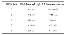
도 7은 본 발명에 적용된 무인 이동체의 모든 출력 액션을 설명하기 위한 도면이다.
도 8과 도 9는 본 발명에 적용된 타겟 크기를 줄이는 방식과 일반적인 타겟 크기로 DQN 기반 학습을 수행할 때의 결과를 설명하기 위한 도면이다.
도 10은 본 발명에 적용된 사람이 서있거나 걸어 다니는 환경에서 DQN 기반 학습을 수행할 때의 결과를 설명하기 위한 도면이다.
도 11은 본 발명의 일 실시예에 따른 DQN 및 SLAM 기반의 맵리스 내비게이션 시스템에 적용된 뎁스 카메라의 시야각을 설명하기 위한 도면이다.
도 12는 발명의 일 실시예에 따른 DQN 및 SLAM 기반의 맵리스 내비게이션 시스템에 적용된 속도에 따른 라이더 오프셋의 차이를 설명하기 위한 도면이다.
도 13은 발명의 일 실시예에 따른 DQN 및 SLAM 기반의 맵리스 내비게이션 시스템에 적용된 라이더 오프셋 알고리즘을 설명하기 위한 도면이다.
도 14는 발명의 일 실시예에 따른 DQN 및 SLAM 기반의 맵리스 내비게이션 시스템에 의한 영상 인식과 라이더 데이터의 오프셋을 설명하기 위한 도면이다.
도 15는 발명의 일 실시예에 따른 DQN 및 SLAM 기반의 맵리스 내비게이션 시스템에 의해 서있는 사람과 물체의 결과를 나타낸 도면이다.
도 16은 발명의 일 실시예에 따른 DQN 및 SLAM 기반의 맵리스 내비게이션 시스템에 의해 움직이는 사람과 물체의 결과를 나타낸 도면이다.
도 17은 발명의 일 실시예에 따른 DQN 및 SLAM 기반의 맵리스 내비게이션 시스템에 의해 무인 이동체가 움직이고 있는 공간에 대해 자율적인 SLAM을 수행한 결과를 나타낸 도면이다.
도 18은 본 발명의 일 실시예에 따른 장애물의 특성을 고려한 DQN 및 SLAM 기반의 맵리스 내비게이션 처리 방법의 동작과정을 상세하게 나타낸 순서도이다.1 is a diagram showing the configuration of a mapless navigation system based on DQN and SLAM considering the characteristics of obstacles according to an embodiment of the present invention.
2 is a diagram for explaining in detail a DQN and SLAM-based mapless navigation process in consideration of the characteristics of obstacles to which the present invention is applied.
3 is a diagram for explaining an experimental environment of mapless navigation based on DQN and SLAM according to an embodiment of the present invention.
4 is a diagram for explaining a target size applied to mapless navigation based on DQN and SLAM according to an embodiment of the present invention.
5 is a diagram for explaining a reward type and a value when performing DQN-based learning applied to the present invention.
6 is a diagram for explaining the structure of a DQN applied to the present invention.
7 is a view for explaining all output actions of the unmanned moving object applied to the present invention.
8 and 9 are diagrams for explaining a method of reducing the target size applied to the present invention and a result of performing DQN-based learning with a general target size.
10 is a diagram for explaining a result of performing DQN-based learning in an environment in which a person to which the present invention is applied stands or walks.
11 is a view for explaining a viewing angle of a depth camera applied to a mapless navigation system based on DQN and SLAM according to an embodiment of the present invention.
12 is a diagram for explaining a difference in a rider offset according to a speed applied to a mapless navigation system based on DQN and SLAM according to an embodiment of the present invention.
13 is a diagram for explaining a lidar offset algorithm applied to a mapless navigation system based on DQN and SLAM according to an embodiment of the present invention.
14 is a diagram for explaining image recognition and an offset of lidar data by a mapless navigation system based on DQN and SLAM according to an embodiment of the present invention.
15 is a diagram illustrating results of standing people and objects by the mapless navigation system based on DQN and SLAM according to an embodiment of the present invention.
16 is a diagram illustrating results of people and objects moving by a mapless navigation system based on DQN and SLAM according to an embodiment of the present invention.
17 is a diagram illustrating a result of performing autonomous SLAM on a space in which an unmanned mobile body is moving by a mapless navigation system based on DQN and SLAM according to an embodiment of the present invention.
18 is a flowchart illustrating in detail an operation process of a method for processing mapless navigation based on DQN and SLAM in consideration of obstacle characteristics according to an embodiment of the present invention.
이하, 첨부한 도면을 참조하여 본 발명의 장애물의 특성을 고려한 DQN 및 SLAM 기반의 맵리스 내비게이션 시스템 및 그 처리 방법에 대한 바람직한 실시 예를 상세히 설명한다. 각 도면에 제시된 동일한 참조부호는 동일한 부재를 나타낸다. 또한 본 발명의 실시 예들에 대해서 특정한 구조적 내지 기능적 설명들은 단지 본 발명에 따른 실시 예를 설명하기 위한 목적으로 예시된 것으로, 다르게 정의되지 않는 한, 기술적이거나 과학적인 용어를 포함해서 여기서 사용되는 모든 용어들은 본 발명이 속하는 기술분야에서 통상의 지식을 가진 자에 의해 일반적으로 이해되는 것과 동일한 의미를 가지고 있다. 일반적으로 사용되는 사전에 정의되어 있는 것과 같은 용어들은 관련 기술의 문맥상 가지는 의미와 일치하는 의미를 가지는 것으로 해석되어야 하며, 본 명세서에서 명백하게 정의하지 않는 한, 이상적이거나 과도하게 형식적인 의미로 해석되지 않는 것이 바람직하다.Hereinafter, a preferred embodiment of a DQN- and SLAM-based mapless navigation system in consideration of the characteristics of an obstacle according to the present invention and a processing method thereof will be described in detail with reference to the accompanying drawings. The same reference numerals shown in each drawing indicate the same members. In addition, specific structural or functional descriptions for the embodiments of the present invention are only exemplified for the purpose of describing the embodiments according to the present invention, and unless otherwise defined, all terms used herein, including technical or scientific terms They have the same meaning as commonly understood by those of ordinary skill in the art to which the present invention pertains. Terms such as those defined in a commonly used dictionary should be interpreted as having a meaning consistent with the meaning in the context of the related art, and should not be interpreted in an ideal or excessively formal meaning unless explicitly defined in the present specification. It is preferable not to
도 1은 본 발명의 일 실시예에 따른 장애물의 특성을 고려한 DQN 및 SLAM 기반의 맵리스 내비게이션 시스템의 구성을 나타낸 도면이다.1 is a diagram showing the configuration of a mapless navigation system based on DQN and SLAM considering the characteristics of obstacles according to an embodiment of the present invention.
도 1에 도시된 바와 같이, 본 발명의 DQN 및 SLAM 기반의 맵리스 내비게이션 시스템(100)은 스마트 팩토리에서 자율 주행을 수행하기 위한 로봇, 차량, 드론 등의 무인 이동체에 적용되는 구성으로서, 가상 환경 구축 모듈(110), 센서(120), 학습 모듈(130), 라이더 데이터 오프셋 모듈(140), 맵 생성 모듈(150), 제어 모듈(160), 메모리(170) 등을 포함하여 구성된다.As shown in FIG. 1 , the DQN and SLAM-based
또한 상기 DQN 및 SLAM 기반의 맵리스 내비게이션 시스템(100)은 도면에 도시하지는 않았지만, 각 구성 부분에 동작전원을 공급하는 전원부, 각종 기능에 대한 데이터 입력을 위한 입력부, 각종 동작프로그램의 업데이트를 관리하는 업데이트 관리부 등을 추가로 포함할 수 있다.In addition, although the DQN and SLAM-based
상기 가상 환경 구축 모듈(110)은 실제 무인 이동체의 환경에서 학습을 수행할 경우 안전성 및 효율성의 문제가 발생되기 때문에, 예를 들어 로봇의 프로그래밍에 사용되는 ROS(Robot Operating System)와 물리엔진 기반의 가상 시뮬레이션 툴(예: GAZEBO)을 사용하여 시뮬레이션을 구성하는 부분이다.Since the virtual environment building module 110 has problems of safety and efficiency when learning is performed in an environment of an actual unmanned moving object, for example, ROS (Robot Operating System) used for robot programming and a physics engine-based This is the part that configures the simulation using a virtual simulation tool (eg GAZEBO).
즉, 상기 가상 환경 구축 모듈(110)은 멈춰있거나 이동중인 적어도 하나 이상의 사람, 적어도 하나 이상의 물체 또는 이들의 조합을 포함한 장애물의 실제 공간에 대한 가상 공간을 생성하고, 상기 생성한 가상 공간 상에 영상인식 및 거리측정을 위한 센서(120)가 구비된 무인 이동체의 스타트 지점과 타겟 지점을 설정하는 것이다.(도 3 참조)That is, the virtual environment building module 110 creates a virtual space for the real space of an obstacle including at least one or more people, at least one or more objects, or a combination thereof, which is stopped or moving, and an image on the created virtual space. It is to set the start point and the target point of the unmanned moving object equipped with the sensor 120 for recognition and distance measurement (see FIG. 3).
상기 센서(120)는 뎁스 카메라(121)와 라이더 측정기(122)를 포함하고, 영상 촬영 정보 및 거리측정 정보를 상기 학습 모듈(130)로 출력한다. 이때 상기 거리측정 정보는 상기 라이더 데이터 오프셋 모듈(140)로 출력한다.The sensor 120 includes a
상기 뎁스 카메라(121)의 경우 시야각은 60도, 프레임 사이즈는 640x480으로 설정되며, 상기 라이더 측정기(122)의 경우 샘플 수는 60개, 해상도(resolution)는 6도로 설정한다. 이때 상기 해상도를 6도로 설정한 이유는 저 성능의 라이더에서도 대응이 가능하도록 하여 범용성을 높이기 위해서이다.In the case of the
또한 상기 라이더(LiDAR) 측정기(122)는 레이저로 대상물을 조사하여 반사되는 빛을 분석함으로써 거리를 측정하는 원격 감지 장치이다.In addition, the LiDAR measuring device 122 is a remote sensing device that measures the distance by irradiating an object with a laser and analyzing the reflected light.
상기 학습 모듈(130)은 상기 무인 이동체의 주변 환경에 따른 학습을 위해서 도 6과 같이 구성한 DQN을 이용하여, 상기 가상 환경 구축 모듈(110)에 구축한 서있거나 또는 움직이는 사람, 적어도 하나 이상의 물체(예: 표면이 딱딱하거나 소프트한 것으로 구분되는 장비, 고가 또는 저가의 장비 등) 또는 이들의 조합을 포함한 가상의 공간에서, 무인 이동체의 현재 상태에서 다음 상태로의 액션값을 출력하기 위하여 학습을 수행한다. 즉 각 에피소드에 따른 학습을 수행할 때, 각 스텝 타임마다 상기 무인 이동체에 구비된 라이더 측정기(122)를 통해 주변을 스캔한 데이터들을 모으고 쌓아서 만든 스택(즉 라이더에 의한 거리 데이터)을 참조하여 액션을 선택하는 것이다.The
보다 구체적으로 설명하면, 상기 학습 모듈(130)은 현재 상태에서 다음 상태로의 무인 이동체에 대한 액션을 출력하기 위하여, 상기 무인 이동체와 타겟 지점 사이의 각도 및 거리 데이터, 상기 무인 이동체에 구비된 상기 라이더 측정기(122)에서 측정한 소정 각도별 라이더 데이터를 학습하고, 상기 학습한 결과를 상기 제어 모듈(160)로 출력하는 것이다.More specifically, in order to output an action for the unmanned moving object from the current state to the next state, the
예를 들어, 상기 학습 모듈(130)은 특정 에피소드를 최초에 수행할 때 상기 타겟 지점의 반경을 원래 크기의 정수 배(바람직하게는 2배)로 확장하여 설정하고, 상기 에피소드의 수행에 따라 상기 무인 이동체가 상기 타겟 지점에 도착할 때마다 상기 타겟 지점의 반경을 기 설정된 범위(바람직하게는 1%)로 줄여 다음의 에피소드를 수행하며, 상기 타겟 지점의 반경이 원래 크기가 될 때까지 각 에피소드를 수행함으로써, 탐색 범위를 좁혀 학습 시간을 단축할 수 있도록 한다.For example, the
이처럼, 초기 타겟 지점의 크기를 정수 배로 키우고 크기를 줄여나가면서 학습을 수행하게 되면, 상기 무인 이동체의 탐색 범위가 좁혀지고, 이에 따라 DQN을 수행하면서 타겟 지점이 어려운 위치에 존재할 때 타겟 지점을 찾지 못하고 시간이 과도하게 오래 걸리는 상황을 방지할 수 있게 된다.In this way, if the size of the initial target point is increased by an integer multiple and learning is performed while the size is reduced, the search range of the unmanned moving object is narrowed, and thus the target point is found when the target point is in a difficult position while performing DQN. This will help avoid situations that take too much time.
이때 상기 에피소드는 상기 무인 이동체가 타겟 지점에 도착하거나, 벽, 장애물 및 사람과 충돌이 발생하거나, 또는 상기 타겟 지점에 기 설정된 시간(예: 200초) 이내에 도착하지 못했을 경우를 하나의 에피소드로 설정한다. 또한 상기 충돌은 상기 무인 이동체가 벽, 장애물 및 사람의 기 설정된 범위 이내로 접근하였을 때를 충돌로 판정한다.In this case, the episode is set as one episode when the unmanned moving object arrives at the target point, collides with a wall, an obstacle, or a person, or does not arrive within a preset time (eg, 200 seconds) at the target point do. In addition, the collision is determined as a collision when the unmanned moving object approaches within a preset range of a wall, an obstacle, and a person.
상기 라이더 데이터 오프셋 모듈(140)은 상기 학습 모듈(130)을 통해 학습을 수행하는 과정에서, 상기 장애물이 감지되면 영상인식 및 거리측정 정보를 토대로 상기 장애물의 종류, 속도 또는 이들의 조합을 포함한 특성을 확인하고, 상기 확인한 장애물의 특성에 따라 사전에 설정한 안전거리의 가중치를 차등적으로 부여하여 라이더 데이터를 오프셋하고, 상기 오프셋한 라이더 데이터를 상기 맵 생성 모듈(150)로 출력한다.In the process of performing learning through the
즉 상기 라이더 데이터 오프셋 모듈(140)은 사람이나 여러 물체를 포함한 장애물을 검출하고, 상기 검출한 장애물의 종류에 따라 안전거리의 가중치를 변경하여 라이더 데이터를 오프셋하고, 이를 토대로 상기 맵 생성 모듈(150)에서 상기 장애물에 대한 경계면을 맵 상에 업데이트하여 표시할 수 있도록 함으로써, 상기 학습 모듈(130)에서 상기 무인 이동체가 안전하게 최적의 경로로 이동할 수 있도록 학습하는 데 도움을 주는 것이다.That is, the lidar data offset module 140 detects an obstacle including a person or several objects, and offsets the lidar data by changing the weight of the safety distance according to the type of the detected obstacle, and based on this, the map generating module 150 ), by updating and displaying the boundary surface for the obstacle on the map, it helps the
이를 구체적으로 설명하면, 상기 라이더 데이터 오프셋 모듈(140)은 상기 무인 이동체의 뎁스 카메라(121)에서 촬영한 상기 장애물의 뎁스 데이터 및 영상인식에 따른 바운딩 박스 데이터를 토대로 상기 장애물을 감지하여 상기 장애물의 종류를 확인한다. 이때 본 발명에서는 상기 영상인식을 위한 알고리즘으로 You Only Look Once(YOLO) 네트워크를 사용한다.Specifically, the lidar data offset module 140 detects the obstacle based on the depth data of the obstacle photographed by the
그리고 상기 라이더 데이터 오프셋 모듈(140)은 상기 장애물이 감지되면 상기 무인 이동체의 라이더 측정기(122)에서 측정한 현재 상태와 이전 상태간의 라이더 데이터의 차이를 계산한 다음, 상기 계산한 라이더 데이터의 차이를 통해서 상기 장애물의 위치를 확인한다.And when the obstacle is detected, the lidar data offset module 140 calculates the difference in lidar data between the current state and the previous state measured by the lidar meter 122 of the unmanned moving object, and then calculates the difference between the calculated lidar data Check the location of the obstacle through
그리고 상기 라이더 데이터 오프셋 모듈(140)은 상기 확인한 장애물의 종류에 따라 상기 확인한 장애물의 위치로부터 설정해야 할 안전거리를 차등적으로 부여하고, 상기 장애물과, 상기 차등적으로 부여한 안전거리에 대한 라이더 데이터의 오프셋을 수행한다.And the lidar data offset module 140 differentially gives a safety distance to be set from the position of the identified obstacle according to the type of the identified obstacle, and rider data for the obstacle and the differentially assigned safety distance perform an offset of
이때 상기 오프셋된 라이더 데이터는 ROS용의 데이터 메시지 폼으로 변환되어 상기 맵 생성 모듈(150)로 출력된다.At this time, the offset lidar data is converted into a data message form for ROS and output to the
상기 맵 생성 모듈(150)은 상기 라이더 데이터 오프셋 모듈(140)로부터 오프셋한 라이더 데이터를 입력받아 상기 장애물에 대한 경계면을 맵 상에 업데이트하여 표시한다.The
즉 상기 라이더 데이터 오프셋 모듈(140)로부터 제공받은, 장애물이 감지된 지점을 기준으로 장애물의 위치로부터 설정해야 할 경계면의 거리만큼 오프셋을 수행한 정보를 SLAM에 적용하여 장애물에 대한 경계면이 맵 상에 표시되도록 하는 것이다.That is, the information obtained from the lidar data offset module 140 and offset by the distance of the boundary to be set from the position of the obstacle based on the point at which the obstacle is detected is applied to SLAM so that the boundary surface for the obstacle is displayed on the map. to make it displayed.
이때 상기 장애물에 대한 경계면이 업데이트된 맵은 상기 학습 모듈(130)에서 다음 번 에피소드를 수행할 때 상기 무인 이동체의 현재 상태에서 다음 상태로의 액션을 출력하기 위한 학습에 이용된다.In this case, the updated map of the boundary surface for the obstacle is used for learning to output an action from the current state to the next state of the unmanned moving object when the next episode is performed in the
상기 제어 모듈(160)은 상기 가상 환경 구축 모듈(110), 센서(120), 학습 모듈(130), 라이더 데이터 오프셋 모듈(140) 및 맵 생성 모듈(150)의 동작을 총괄적으로 제어하는 부분이다.The
상기 메모리(170)는 상기 무인 이동체에서 사용되는 각종 동작프로그램을 저장하고 있다.The
또한 상기 메모리(170)는 상기 학습 모듈(130)에서 수행한 학습 모델을 저장하고 있으며, 상기 맵 생성 모듈(150)을 통해 구현된 SLAM 정보를 저장한다.In addition, the
이와 같이 구성된 본 발명의 DQN 및 SLAM 기반의 맵리스 내비게이션 처리과정을 도 2를 참조하여 상세하게 설명하면 다음과 같다.The DQN and SLAM-based mapless navigation process of the present invention configured as described above will be described in detail with reference to FIG. 2 as follows.
도 2는 본 발명이 적용된 DQN 및 SLAM 기반의 맵리스 내비게이션 처리과정을 상세하게 설명하기 위한 도면이다.2 is a diagram for explaining in detail a process of mapless navigation based on DQN and SLAM to which the present invention is applied.
도 2에 도시된 바와 같이, 상기 학습 모듈(130)은 각 에피소드별로 사람, 물체 또는 이들의 조합을 포함한 장애물이 포함된 소정의 공간에서 타겟 지점까지의 각도 및 거리 정보, 소정 각도별 라이더 데이터를 입력으로 하여 학습을 수행하고, 학습 결과에 따라 상기 무인 이동체의 현재 상태에서 다음 상태로의 액션값을 출력한다.As shown in Figure 2, the
또한 상기 라이더 데이터 오프셋 모듈(140)은 상기 학습 모듈(130)에 의한 학습이 진행되는 과정에서, 장애물이 감지되면 상기 뎁스 카메라(121)로 촬영한 로우 뎁스 데이터(depth_raw)와, 로우 이미지 데이터(image_raw)로부터 영상인식을 수행한 바운딩 박스(bounding box) 데이터와, 라이더 측정기(122)에서 측정한 소정 각도별 라이더 데이터를 입력으로 하여 상기 감지된 장애물의 종류, 속도 등의 특성을 확인한다.In addition, the lidar data offset module 140, when an obstacle is detected in the process of learning by the
또한 상기 라이더 데이터 오프셋 모듈(140)은 상기 확인한 장애물의 특성에 따라 사전에 설정한 안전거리의 가중치를 차등적으로 부여하여 라이더 데이터를 오프셋하고, 상기 오프셋한 데이터를 ROS로 변환하여 상기 맵 생성 모듈(150)로 출력한다.In addition, the lidar data offset module 140 offsets the lidar data by differentially assigning a weight of a safety distance set in advance according to the identified obstacle characteristics, and converts the offset data into ROS to generate the map. (150) is output.
이때 상기 사전에 설정한 안전거리는 움직이는 사람, 서 있는 사람, 고가 장비, 저가 장비의 순서로 점차 줄어들도록 설정된다.At this time, the preset safety distance is set to gradually decrease in the order of a moving person, a standing person, a high-priced device, and a low-cost device.
이에 따라 상기 맵 생성 모듈(150)은 상기 오프셋 정보를 SLAM에 적용하여 장애물에 대한 경계면을 맵 상에 표시한다.Accordingly, the
이와 같이 상기 무인 이동체의 액션 출력을 위한 학습 및 장애물의 특성에 따른 안전거리 가중치의 차등 적용을 토대로 최종적인 학습 모델과 각종 장애물 특성이 고려된 맵이 완성된다.In this way, a final learning model and a map in which various obstacle characteristics are considered are completed based on the learning for the action output of the unmanned moving object and the differential application of the safety distance weight according to the characteristics of the obstacle.
다음에는, 이와 같이 구성된 본 발명에 따른 장애물의 특성을 고려한 DQN 및 SLAM 기반의 맵리스 내비게이션에 대하여 도 3 내지 도 10을 참조하여 보다 상세하게 설명한다.Next, mapless navigation based on DQN and SLAM considering the characteristics of obstacles according to the present invention configured as described above will be described in more detail with reference to FIGS. 3 to 10 .
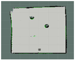
도 3은 본 발명의 일 실시예에 따른 DQN 및 SLAM 기반의 맵리스 내비게이션의 실험 환경을 설명하기 위한 도면으로서, 본 발명에서는 우선 도 3의 (a)에 나타낸 바와 같이 뎁스 카메라(121)와 라이더 측정기(122)가 구비된 실제 세계(real world)의 무인 이동체를 가상의 공간 상에 구현한다.FIG. 3 is a diagram for explaining an experimental environment of mapless navigation based on DQN and SLAM according to an embodiment of the present invention. In the present invention, first, as shown in FIG. 3A , the
또한 도 3의 (b)에 나타낸 바와 같이 소정 크기(예: 6m x 6m)의 직사각형 가상 공간 내부에 고정된 원통형의 장애물 2개를 배치한다. 본 발명의 실험에서는 상기 장애물의 크기는 반지름 0.3m로 설정하고, 약 2m 간격으로 설치하며, 타겟 지점(goal position)의 좌표는 장애물 주변의 미리 지정된 8개의 좌표에서 랜덤하게 설정한다.In addition, as shown in FIG. 3B , two fixed cylindrical obstacles are arranged inside a rectangular virtual space of a predetermined size (eg, 6m x 6m). In the experiment of the present invention, the size of the obstacle is set to a radius of 0.3 m, installed at an interval of about 2 m, and the coordinates of the target position are randomly set at eight predetermined coordinates around the obstacle.
또한 서 있는 사람이나 움직이는 사람 이외에, 다양한 장애물을 가상환경에서 구현하는 것이 쉽지 않기 때문에, 본 발명에서는 도 3의 (c)에 나타낸 바와 같이 고가의 장애물은 모니터, 저가의 장애물은 컵으로 대체하여 이미지화한 후 배치한다.In addition, since it is not easy to implement various obstacles in a virtual environment other than a standing person or a moving person, in the present invention, an expensive obstacle is replaced with a monitor and a low-priced obstacle is imaged with a cup, as shown in FIG. After that, place
상기 도 3에서 구현한 가상 환경을 토대로, 상기 학습 모듈(130)에 적용되는 DQN을 설명하면 다음과 같다.Based on the virtual environment implemented in FIG. 3 , the DQN applied to the
강화학습은 학습 및 제어의 주체인 에이전트의 최적화 제어(Optimal Control) 문제를 위하여 Bellman이 Markov Decision Process(MDP)를 기반으로 만든 Bellman Equation을 기초로 한다. 먼저 상기 MDP는 처음 시간 t = 0에서 어떠한 상태 S0로부터 시작하여 현재의 상태 St로 도착할 확률이 바로 이전의 상태 St-1에서 현재의 상태 St까지 올 확률과 같다면 이는 Markov하다고 표현하며, 아래의 수학식 1로 표현할 수 있다Reinforcement learning is based on Bellman Equation created by Bellman based on Markov Decision Process (MDP) for the optimization control problem of the agent, which is the subject of learning and control. First, the MDP is expressed that the first time t = surface starting from any state S 0 from 0 to as Chance in the immediately previous state S t-1 probability to get to the current state S t to the current state S t which Markov and can be expressed as
[수학식 1][Equation 1]

여기서 액션 At는 에이전트가 취하는 액션을 나타내며, 리워드 Rt는 에이전트가 액션을 취한 후의 환경, 즉 주변 환경을 고려하였을 때 얼마나 의도한대로 움직였는지를 수치적으로 나타낸다. 강화학습은 일반적으로 상태 St가 이전의 상태 St-1과 Markov한 관계를 가진다고 가정하고 학습을 수행하기 때문에 한 에피소드가 끝난 후 받은 리워드는 이전의 상태들과 관련이 있다고 할 수 있으며, 위의 관계를 이용하여 DQN의 학습을 위한 가치 함수(Value Function)를 유도한다. 에이전트는 각 스텝마다 액션을 취했을 때 외란 등에 의해 상태 St에 확률적으로 도달하게 되며 이 상태에 따른 리워드를 즉시 얻게 된다.Here, the action A t represents the action taken by the agent, and the reward R t numerically represents how much the agent moved as intended considering the environment after the action was taken, that is, the surrounding environment. Reinforcement learning generally assumes that the state S t has a Markov relationship with the previous state S t-1 and performs learning, so it can be said that the reward received after one episode is related to the previous states, A value function for DQN learning is derived using the relationship of When the agent takes an action at each step , it probabilistically reaches the state S t due to disturbance, etc., and immediately obtains a reward according to this state.
한 에피소드가 끝났을 때 매 타임 스텝에서 받은 리워드의 총 합이 높을수록 학습이 잘 되었다고 할 수 있으며, 에이전트의 상태에 따라 얻을 수 있는 리워드 총합의 기댓값은 State Value Function이라 표현한다.At the end of an episode, the higher the sum of rewards received at each time step, the better the learning. The expected value of the sum of rewards that can be obtained according to the agent's state is expressed as a State Value Function.
State Value Function은 수학식 2와 같이 나타낼 수 있다.The State Value Function can be expressed as Equation (2).
[수학식 2][Equation 2]
![]()
![]()
기댓값으로 나타내는 이유는 에이전트가 상태 St에 도달하는 것은 확률에 따르기 때문이며, Gt는 환경으로부터 얻은 리워드의 총합을 나타내고 수학식 3과 같이 나타낼 수 있다.The reason for expressing the expected value is that the agent reaches the state S t according to the probability, and G t represents the sum of the rewards obtained from the environment and can be expressed as in
[수학식 3][Equation 3]

이때 위의 식에서 ![]()
![]()
수학식 2의 State Value Function은 상태와 리워드의 관계만 고려되어 있으나, 에이전트의 액션을 결정하는 정책 또한 반드시 고려되어야 한다. 이는 정책 π가 시간 t에서 에이전트가 상태 St를 가질 때 액션 At를 취할 확률을 나타내기 때문이며, 이를 수식으로 나타내면 아래의 수학식 4와 같이 표현할 수 있다.In the State Value Function of
[수학식 4][Equation 4]
![]()
![]()
에이전트가 정책 ![]()
![]()
[수학식 5][Equation 5]
![]()
![]()
Q 러닝의 기반이 되는 Bellman Equation은 다음 시간의 상태 St+1과 현재 상태 St의 State Value Function 관계를 수식으로 정의한 것인데, 위의 리워드의 총합에 관한 수식 및 Value Function을 사용하여 이를 구할 수 있다. 수학식 3을 수학식 5에 대입하면 아래의 수학식 6과 같이 나타낼 수 있다.Bellman Equation, which is the basis of Q-learning, is a formula that defines the state value function relationship between the state S t+1 at the next time and the current state S t. have. Substituting
[수학식 6][Equation 6]

상기 수학식 6에서 ![]()
![]()
[수학식 7][Equation 7]
![]()
![]()
상기 수학식 7에서 Gt+1은 ![]()
![]()
[수학식 8][Equation 8]
![]()
![]()
상기 수학식 8에서 Rt+1은 현재의 상태 St가 주어졌을 때 환경으로부터 즉시 받는 리워드이며, ![]()
![]()
여기서 Expectation은 어떠한 액션 a를 취할 확률을 나타내는 정책에 의존하기 때문에 나온 것이라고 할 수 있다. 확률과 기대 이득의 곱의 합이라는 Expectation의 정의에 따라 수학식 8은 다음의 수학식 9와 같이 표현할 수 있다.Here, Expectation can be said to arise because it depends on the policy indicating the probability of taking some action a. According to the definition of Expectation, which is the sum of the product of probability and expected gain,
[수학식 9][Equation 9]
![]()
![]()
DQN을 수행하면서 에이전트는 이러한 Value Function을 이용해 해당 시간의 상태 St에서 최고의 리워드를 얻을 수 있는 상태 St+1로 이동시켜야 한다. 그런데 상기 수학식 9에서 식 ![]()
![]()
따라서 DQN에서는 환경에 대한 모델링이 필요 없는 모델 프리(Model Free) 방법을 위하여 Action Value Function을 사용한다. 현재의 상태 St에서 액션을 취한 후의 Value Function을 구하면 다음 시간의 모든 가능한 상태 St+1에 대한 모든 Value Function을 구할 필요가 없어지므로 식을 간략화 할 수 있는데, 이를 Action Value Function 혹은 Q Function라고 하며 수학식 10과 같이 나타낸다.Therefore, DQN uses Action Value Function for a model-free method that does not require modeling of the environment. Finding the Value Function after taking an action in the current state S t eliminates the need to find all Value Functions for all possible states S t+1 in the next time, so the expression can be simplified, which is called Action Value Function or Q Function. and is expressed as
[수학식 10][Equation 10]
![]()
![]()
Action Value Function 또한 앞서 State Value Function과 같은 방식으로 수학식 11과 같이 정리한다.The Action Value Function is also arranged as in Equation 11 in the same manner as the State Value Function above.
[수학식 11][Equation 11]

상기 Action Value Function은 상태 St 및 액션 At에 따라 결정되며 강화학습에서 사용되는 Model Free 방법에서는 확률이 아닌 경험을 기반으로 하기 때문에 수학식 11과 같이 정리된다. 해당 수학식에서 받을 수 있는 최대의 값인 Optimal Action Value Function ![]()
![]()
[수학식 12][Equation 12]
![]()
![]()
여기서 ![]()
![]()
![]()
![]()
[수학식 13][Equation 13]
![]()
![]()
여기서 최적 정책은 Action Value Function을 최대로 하는 액션 At를 선택하게 되는데 이를 greedy 방법이라 한다. 상기 설명을 정리하면 DQN은 Action Value Function을 인공신경망으로 구현하고 현재의 상태 St 및 최적 정책에 따라 최대의 Q Value 혹은 리워드를 가지는 액션 At를 선택하는 것이다. 따라서 DQN의 목적은 이 Q Function을 나타내는 인공 신경망을 구성하고 학습하는 것이라고 할 수 있다. Here, the optimal policy selects the action A t that maximizes the Action Value Function, which is called the greedy method. To summarize the above description, DQN implements the Action Value Function as an artificial neural network and selects the action A t having the maximum Q Value or reward according to the current state St and the optimal policy. Therefore, it can be said that the purpose of DQN is to construct and train an artificial neural network representing this Q function.
이러한 Q Function은 액션의 리워드를 평가하는 Evaluation 및 신경망의 업데이트를 나타내는 Improvement의 반복 과정인 Policy Iteration을 통해 구할 수 있다.This Q function can be obtained through Policy Iteration, an iterative process of Evaluation that evaluates the reward of an action, and Improvement, which indicates the update of the neural network.
Value Evaluation은 시간 t에서 주어진 정책 및 상태에 대하여 얻을 수 있는 리워드의 예측 값을 계산 하는 것을 뜻하며 이 값을 이용해 Q Function에 대한 업데이트를 수행 한다. 이 과정을 Improvement라고 칭하며 DQN에서는 ![]()
![]()
이와 반대로 Temporal Difference Method는 Dynamic Programming처럼 타임 스텝마다 업데이트가 가능하다는 장점이 있다. Monte Carlo Method은 하나의 에피소드가 종료되었을 때 즉, 정확한 목표 지점에 도착해야만 업데이트를 시작하므로 정답에 대한 학습이 가능하지만 그로 인하여 도착이 늦기 때문에 비교적 Variance가 높다. 반대로 Temporal Difference는 목표에 도착하기 전에도 계속 학습을 수행하므로 Variance가 크지는 않으나 가는 도중에도 학습해야 하므로 정확한 목표를 사용할 수 없어 Bias가 비교적 높다. 따라서 Temporal Difference를 사용할 때 매 타임 스텝이 아닌 Interval의 적절한 선택을 통해 Variance와 Bias를 고려해 Trade Off한다.Conversely, the Temporal Difference Method has the advantage that it can be updated every time step like Dynamic Programming. The Monte Carlo method starts updating only when an episode ends, that is, when it arrives at the correct target point, so it is possible to learn the correct answer, but it has a relatively high variance because it arrives late. Conversely, since the Temporal Difference continues to learn even before reaching the target, the variance is not large, but since it needs to learn on the way, the exact target cannot be used, so the bias is relatively high. Therefore, when using Temporal Difference, trade off considering variance and bias through appropriate selection of interval rather than every time step.
한편, Temporal Difference Method에서 Q Function을 업데이트하고 사용하는 방법에는 크게 On-Policy와 Off-Policy의 2가지 방법이 존재한다. On-Policy에서는 에이전트를 제어하는데 사용되는 Policy와 업데이트 하는 Policy를 따로 구분하여 사용하지 않으며, 이 경우에는 하나의 Policy에 따라 액션을 수행하고 이 결과에 대한 학습을 반복한다. 이에 따라 탐험을 수행하기 힘들고 이 때문에 Local Minimum에 빠질 위험이 높으며 학습초기에 업데이트와 액션이 같은 신경망을 이용해 진행되기 때문에 업데이트에 의한 가중치의 변화가 심하여 안정적인 학습이 어렵다.On the other hand, there are two main methods for updating and using the Q function in the Temporal Difference Method: On-Policy and Off-Policy. In On-Policy, the policy used to control the agent and the policy to update are not used separately. In this case, an action is performed according to one policy and learning about the result is repeated. As a result, it is difficult to perform exploration, and for this reason, there is a high risk of falling into the local minimum, and since updates and actions are performed using the same neural network in the early stages of learning, stable learning is difficult because the weight changes due to updates are severe.
이러한 단점을 개선하기 위해 하나의 Policy를 두 가지로 나눈 것이 Off-Policy인데, 이는 에이전트의 제어를 위한 behavior Policy 외에 Target Policy를 따로 두고 업데이트를 수행하는 방법을 뜻하며, 이것이 일반적인 Q Learning의 구조라고 할 수 있다.In order to improve this shortcoming, one policy is divided into two off-Policy, which means a method of performing updates by setting a target policy in addition to the behavior policy for agent control, and this is the general structure of Q Learning. can
이러한 구조의 장점은 behavior Policy와 다른, Target Policy를 목표로 업데이트함과 동시에 에이전트가 액션을 임의로 수행하며 경험을 쌓고 환경에 대한 탐험을 할 수 있다는 점이다.The advantage of this structure is that, while updating the target policy as a goal, which is different from the behavior policy, the agent can arbitrarily perform actions, gain experience, and explore the environment.
먼저 Q Learning에서 Target Policy는 가장 큰 Q Value를 가지는 값을 선택하여 업데이트하는 greedy 방법을 사용한다. 이를 적용한 Q의 Target Value는 다음의 수학식 14와 같이 표현할 수 있다.First, in Q Learning, the target policy uses a greedy method that selects and updates the value with the largest Q Value. The target value of Q to which this is applied can be expressed as in Equation 14 below.
[수학식 14][Equation 14]
![]()
![]()
이를 수학식 11에 대입하면 다음의 수학식 15와 같이 정리할 수 있다.Substituting this into Equation 11, it can be summarized as
[수학식 15][Equation 15]

상기 수학식 11의 정의 및 Target Policy의 역할에 따라 수학식 15는 인공 신경망의 Target Value가 된다. 하지만 이 방법을 사용할 경우 신경망은 항상 바로 앞의 Max Q Value만을 교육하기 때문에 미래에 더 높은 리워드를 받을 수 있는 액션에 대해 탐색이 불가능하며 다양한 환경에서 적용이 힘들다. 따라서 Q Learning에서는 이를 바로 업데이트에 이용하는 것이 아니라 ![]()
![]()
![]()
![]()
![]()
![]()
![]()
![]()
![]()
![]()
[수학식 16][Equation 16]

[수학식 17][Equation 17]
![]()
![]()
상기 수학식 16에서 ![]()
![]()
![]()
![]()
![]()
![]()
상기 ![]()
![]()
![]()
![]()
[수학식 18][Equation 18]

상기 수학식 18에서 ![]()
![]()
![]()
![]()
한편 DQN에서는 성능을 높이기 위해 몇 가지 알고리즘이 추가된다. Experience Replay는 DQN이 발전할 수 있도록 한 방법 중 하나로 각 시간에서의 데이터를 바로 신경망에 업데이트하는 것이 아니라 우선 메모리에 저장을 한 후, 데이터가 어느 정도 쌓였을 때 Batch Size만큼의 임의의 샘플을 선택하여 학습한다. 무인 이동체가 주행하면서 얻어진 시계열 데이터를 바로 신경망의 입력으로 사용하여 학습할 경우 유사한 값과 형태의 데이터가 연속적으로 입력 및 학습되어 네트워크가 Local Minimum에 빠질 위험성이 있기 때문이다. 따라서 본 발명에서 DQN을 구현할 때에도 이를 따랐으며 Batch Size는 64로 설정한다. 그리고 학습의 시간 단축을 위해 도 4에 표기한 타겟 사이즈의 변화 방법을 사용한다.Meanwhile, in DQN, several algorithms are added to improve performance. Experience Replay is one of the methods that allowed DQN to develop. Instead of updating the data at each time directly to the neural network, it first stores it in memory, and then selects a random sample as much as the batch size when the data is accumulated to some extent. learn This is because, when the time series data obtained while driving an unmanned vehicle is used as an input to the neural network for learning, similar values and types of data are continuously input and learned, and there is a risk that the network falls into the local minimum. Therefore, this was followed when implementing DQN in the present invention, and the batch size is set to 64. And in order to shorten the learning time, the method of changing the target size shown in FIG. 4 is used.
도 4는 본 발명의 일 실시예에 따른 DQN 및 SLAM 기반의 맵리스 내비게이션에 적용된 타겟 사이즈를 설명하기 위한 도면이다.4 is a diagram for explaining a target size applied to mapless navigation based on DQN and SLAM according to an embodiment of the present invention.
도 4에 도시된 바와 같이, DQN에서는 상기 설명한 바와 같이 탐험과 탐색을 통하여 리워드를 가장 많이 받을 수 있는 Optimal Policy를 찾는다. 다만 이 과정에서 Trial and Error(직접 부딪치며 배우는 것)를 반복하는 강화학습의 특성으로 인해 시간이 과다하게 소요될 가능성이 존재한다. 따라서 본 발명에서는 타겟 지점의 범위를 넓혀서 에이전트가 탐색하는 범위를 좁히는 방안을 제시한다.As shown in FIG. 4 , in DQN, an Optimal Policy that can receive the most rewards is found through exploration and search as described above. However, there is a possibility that excessive time is required due to the nature of reinforcement learning, which repeats Trial and Error (learning by direct encountering) in this process. Therefore, the present invention proposes a method of narrowing the range searched by the agent by expanding the range of the target point.
이 방법은 Epsilon Greedy 방법과 비슷하게 교육 초기에는 도 4와 같이 초기 타겟 지점의 크기를 2배로 키워 무인 이동체의 탐색 범위를 좁힌다. 그리고 무인 이동체가 타겟 지점으로 도착함으로 인해 에피소드가 종료됨에 따라 타겟 지점의 사이즈를 점차 감소시켜서 결국에는 기존의 타겟 지점의 크기와 동일하도록 한다. 예를 들어 본 발명은 상기 도 3과 같이 구현된 가상의 공간에서 초기 타겟 지점의 크기를 2배로 조정하였으며, 상기 무인 이동체가 각 에피소드에 의한 학습에 따라 타겟 지점에 도착할 때마다 1%씩 감소시켜 학습을 진행한다. 상기 학습은 원래의 타겟 크기가 될 때까지 진행된다. 이는 무인 이동체가 DQN을 수행하면서 타겟 지점이 어려운 위치에 존재할 때 타겟 지점을 찾지 못하고 시간이 과도하게 오래 걸리는 상황을 방지하기 위함이다.Similar to the Epsilon Greedy method, this method narrows the search range of the unmanned moving object by doubling the size of the initial target point as shown in FIG. 4 at the beginning of training. And, as the episode ends due to the arrival of the unmanned moving object to the target point, the size of the target point is gradually reduced so that it becomes the same as the size of the existing target point. For example, in the present invention, the size of the initial target point is doubled in the virtual space implemented as shown in FIG. 3, and each time the unmanned moving object arrives at the target point according to the learning by each episode, it is reduced by 1%. proceed with learning. The learning proceeds until the original target size is reached. This is to prevent a situation in which an unmanned moving object cannot find a target point and takes an excessively long time when the target point is in a difficult location while performing DQN.
또한, 본 발명의 실험 환경에서는 도 5에 나타낸 바와 같이 환경에 따른 리워드를 설정한다.In addition, in the experimental environment of the present invention, a reward according to the environment is set as shown in FIG. 5 .
도 5는 본 발명에 적용된 DQN 기반 학습을 수행할 때 리워드 타입 및 값을 설명하기 위한 도면으로서, 본 발명에서는 주행 리워드(driving reward), 타겟 도착 리워드(goal reward), 충돌 리워드(collision reward)로 구분한다.5 is a diagram for explaining a reward type and a value when performing DQN-based learning applied to the present invention. In the present invention, a driving reward, a target arrival reward, and a collision reward are shown. separate
상기 주행 리워드는 매 시간 t에서 받는 리워드로서, 타겟 지점과 무인 이동체의 헤딩 방향에 따라 Heading Reward 및 Distance Reward를 더하여 계산한다. 시간 t에서 상기 무인 이동체와 타겟 지점이 이루는 각도를 ![]()
![]()
![]()
![]()
[수학식 19][Equation 19]
![]()
![]()
[수학식 20][Equation 20]
![]()
![]()
[수학식 21][Equation 21]
![]()
![]()
상기 수학식 19에서 ![]()
![]()
![]()
![]()
한편, 본 발명에서는 상기 무인 이동체의 주변 환경에 따른 주행을 학습하기 위해서 도 6의 네트워크를 구성한다.Meanwhile, in the present invention, the network of FIG. 6 is configured to learn driving according to the surrounding environment of the unmanned moving object.
도 6은 본 발명에 적용된 DQN의 구조를 설명하기 위한 도면으로서, 네트워크의 입력은 라이더의 스캔 데이터와 타겟 지점까지의 거리 및 방향이다.6 is a diagram for explaining the structure of the DQN applied to the present invention, and the input of the network is the scan data of the rider and the distance and direction to the target point.
본 발명의 인공 신경망은 도 6에서와 같이 신경망들을 서로 직접적으로 연결하는 Fully Connected Network 및 Dropout Layer를 사용하여 구성한다.The artificial neural network of the present invention is constructed using a Fully Connected Network and a Dropout Layer that directly connect the neural networks to each other as shown in FIG. 6 .
상기 Drop Out Layer는 인공 신경망을 교육할 때 의도적으로 일부 뉴런에서 다음 뉴런으로 데이터가 전파되는 것을 차단한다. 이는 신경망이 학습에 사용되는 러닝 데이터 세트(Learning Data Set)에 대해 오버피팅(Over Fitting)되는 것을 방지하며, 본 발명에서는 20%로 설정한다. 각 신경망은 가우시안 분포로 초기화되며, 입력 레이어(Input Layer) 및 히든 레이어(Hidden Layer)의 활성화 함수는 ReLU, 출력 레이어(Output Layer)에서는 활성화 함수로 Linear 함수를 사용하여 결과를 출력한다.The Drop Out Layer intentionally blocks data propagation from some neurons to the next when training an artificial neural network. This prevents the neural network from being overfitted with respect to the Learning Data Set used for learning, and is set to 20% in the present invention. Each neural network is initialized with a Gaussian distribution, and the activation function of the input layer and the hidden layer is ReLU, and the output layer uses the Linear function as the activation function to output the result.
DQN의 입력으로 사용되는 관찰된 상태(Observed States)는 라이더(LiDAR)를 통해 얻은 6도 간격의 측정 거리, 그리고 상기 무인 이동체와 타겟 지점 사이의 각도 및 거리로서, 62개의 데이터가 입력된다. 출력 레이어는 상기 무인 이동체의 액션을 결정하며, 결정된 액션에 따른 상기 무인 이동체의 속도는 도 7과 같다.The Observed States used as the input of the DQN are the measured distance at 6-degree intervals obtained through LiDAR, and the angle and distance between the unmanned vehicle and the target point, and 62 pieces of data are input. The output layer determines the action of the unmanned moving object, and the speed of the unmanned moving object according to the determined action is shown in FIG. 7 .
도 7은 본 발명에 적용된 무인 이동체의 모든 출력 액션을 설명하기 위한 도면으로서, 0 내지 4의 5개의 액션별 선속도(linear velocity)와 각속도(angular velocity)가 설정되어 있다.7 is a diagram for explaining all output actions of the unmanned moving object applied to the present invention, in which linear velocity and angular velocity for each of five actions of 0 to 4 are set.
업데이트의 방식을 결정하는 Optimizer는 Stochastic Gradient Descent의 한 종류인 RMSprop를 사용한다. Stochastic Gradient Descent는 모든 데이터를 계산하는 기존의 Gradient Descent와 달리 Mini Batch Size를 사용해 업데이트 속도를 빠르게 한 것이며 Geoffrey Hinton이 제안한 방법에서 기인한다.The optimizer that determines the update method uses RMSprop, a kind of stochastic gradient descent. Unlike the existing gradient descent that calculates all data, stochastic gradient descent uses a mini batch size to speed up the update rate, and it originates from the method proposed by Geoffrey Hinton.
일반적인 Gradient Descent의 경우 i번째 히든 레이어의 가중치를 ![]()
![]()
![]()
![]()
![]()
![]()
[수학식 22][Equation 22]
![]()
![]()
[수학식 23][Equation 23]

[수학식 24][Equation 24]

상기 수학식 22는 i번째 히든 레이어의 출력을 나타내며, 수학식 23은 Cost Function과 가중치의 상관관계를 나타낸다. 가중치에 대한 Cost Function의 변화량이 계속 감소하는 방향으로 가중치를 업데이트하면 최적의 가중치를 찾을 수 있다는 것에 기인하며 이는 수학식 24와 같이 표현된다. 수학식 24에서 ![]()
![]()
[수학식 25][Equation 25]
![]()
![]()
상기 수학식 25는 가중치에 대한 Cost Function을 제곱한 값의 일정 비율을 계속 축적하여 sum of square로 나타낼 수 있는 Gt를 통해 가중치간의 변화량 크기를 비교할 수 있다.In
이를 이용해 기존의 Gradient Descent 업데이트의 수식인 수학식 24를 변경하면 다음의 수학식 26과 같이 나타낼 수 있다.Using this, if Equation 24, which is the equation of the existing gradient descent update, is changed, it can be expressed as Equation 26 below.
[수학식 26][Equation 26]
![]()
![]()
상기 수학식 26에서 ![]()
![]()
도 8과 도 9는 본 발명에 적용된 타겟 크기를 줄이는 방식과 일반적인 타겟 크기로 DQN 기반 학습을 수행할 때의 결과를 설명하기 위한 도면이다.8 and 9 are diagrams for explaining a method of reducing the target size applied to the present invention and a result of performing DQN-based learning with a general target size.
상기 도 8 및 도 9에서 No Decreasing은 타겟 지점 크기의 증감 없이 실험한 결과를 나타내며, Decreasing은 타겟 지점의 크기를 변화시켜가며 시뮬레이션을 수행한 결과를 나타낸다. (a)는 각 에피소드에서 얻은 리워드의 합계, (b)는 Max Q Value 그리고 (c)는 정확도를 나타낸다. 타겟 지점의 크기는 1%씩 감소하며 최종적으로는 원래 크기까지 감소하게 되는데 목표지점에 70회 도착했을 때 목표지점의 크기는 원래 크기와 같은 타겟 지점의 크기를 가진다. 도 8의 경우 에피소드 600회를 지났을 때 타겟 지점에 70회 도착하였으며, (c)에서 2가지 경우를 비교하였을 때 정확도는 에피소드 1000회에서 약 27% 차이를 나타내고 있다.In FIGS. 8 and 9, No Decreasing shows the results of experiments without increasing or decreasing the size of the target point, and Decreasing shows the results of performing the simulation while changing the size of the target point. (a) is the sum of rewards obtained from each episode, (b) is Max Q Value, and (c) is accuracy. The size of the target point decreases by 1% and finally decreases to the original size. When the target point arrives 70 times, the size of the target point has the same size as the original size. In the case of FIG. 8, the target point arrived 70 times after 600 episodes, and when comparing the two cases in (c), the accuracy shows a difference of about 27% in 1000 episodes.
또한 추가적으로 실험한 도 9의 결과를 도 8의 (c)의 정확도를 비교하였을 때, 도 8과 에피소드 1500 이하에서 정확도가 약 40%까지 빠르게 상승하는 결과를 보였으며, 그 이후에도 20% 이상의 차이를 보임을 확인할 수 있다.In addition, when comparing the accuracy of FIG. 8 (c) with the result of the additional experiment of FIG. 9, the accuracy increased rapidly to about 40% in FIG. 8 and
도 10은 본 발명에 적용된 사람이 서있거나 걸어 다니는 환경에서 DQN 기반 학습을 수행할 때의 결과를 설명하기 위한 도면이다.10 is a diagram for explaining a result of performing DQN-based learning in an environment in which a person to which the present invention is applied stands or walks.
도 10에 도시된 바와 같이, 본 발명에서는 사람이 서있거나 걸어 다니는 환경에서 맵리스 내비게이션에 대한 테스트를 수행하였고, 각각의 경우에 대하여 1000회의 에피소드를 수행한 결과는 (a) 및 (b)에 나타낸 바와 같다. 여기서 타겟 지점에 도착한 모든 경우를 goal, optimal path driving의 경우는 optimal로 나타내었으며, optimal path driving은 도 10의 (c)와 같이 장애물 사이를 피해 최단 거리로 주행하는 것을 뜻하며, 이는 에피소드 종료까지의 소요 시간 및 획득한 보상의 크기를 통해 구분하였다.As shown in FIG. 10, in the present invention, a test for mapless navigation was performed in an environment in which a person is standing or walking, and the results of performing 1000 episodes for each case are in (a) and (b). as shown. Here, all cases of arriving at the target point were expressed as goal, and optimal path driving was expressed as optimal, and optimal path driving means driving the shortest distance while avoiding obstacles as shown in FIG. It was classified based on the time required and the size of the reward obtained.
다음에는, 이와 같이 구성된 본 발명에 따른 장애물의 특성에 따른 오프셋 알고리즘에 대하여 도 11 내지 도 16을 참조하여 보다 상세하게 설명한다.Next, the offset algorithm according to the characteristics of the obstacle according to the present invention configured as described above will be described in more detail with reference to FIGS. 11 to 16 .
먼저 본 발명에서는 사람 및 물체를 포함한 장애물을 검출하고 종류에 따라 안전거리의 가중치를 변경하여 무인 이동체가 안전하게 최적의 경로로 이동할 수 있도록 학습한다. 따라서 각 장애물에 대하여 영상으로 인식하기 위해 YOLO 알고리즘을 사용한다.First, in the present invention, obstacles including people and objects are detected and the weight of the safety distance is changed according to the type, so that an unmanned moving object can safely move to the optimal path. Therefore, the YOLO algorithm is used to recognize each obstacle as an image.
이미지를 인식하기 위한 이미지를 인식하기 위한 YOLO 네트워크의 입력으로는 가상으로 구현된 뎁스 카메라로부터 입력받은 640x480 로우 이미지 데이터가 사용되며, 이를 이용해 영상 내에서 장애물들의 위치를 찾고 종류를 구분할 수 있다. 상기 YOLO의 특징은 CNN을 기반으로 하여 많고 다양한 사물들을 빠르게 구분할 수 있다는 장점이 있다. 또한 해당 장애물의 종류와 위치에 대한 데이터를 가지는 바운딩 박스(Bounding Box) 데이터를 얻을 수 있다.640x480 raw image data received from a virtual depth camera is used as an input of the YOLO network for image recognition for image recognition, and it can be used to locate and classify obstacles in an image. The feature of YOLO is that it can quickly classify many and diverse objects based on CNN. In addition, it is possible to obtain bounding box data having data on the type and location of the obstacle.
종래의 SLAM에서는 단순히 라이더의 거리 데이터만 이용하여 맵을 만들기 때문에 공간의 출입 금지 구역, 장애물의 종류 등은 따로 사용자가 수동으로 표기하거나 들어가지 못하도록 조치를 해야 할 필요성이 있다. 따라서 YOLO 네트워크를 이용해 장애물의 종류를 분류한 후, 종류에 따라 안전거리에 대한 가중치를 부여하고, 무인 이동체가 SLAM을 수행하는 시점에서 미리 장애물의 중요성에 따라 맵 위에 안전거리를 다르게 표현함으로써 이점을 가질 수 있다.In the conventional SLAM, since a map is created using only the rider's distance data, there is a need to manually mark or prevent the user from entering the prohibited area of the space, the type of obstacle, and the like. Therefore, after classifying the types of obstacles using the YOLO network, weights are given to the safety distances according to the types, and the safety distances are expressed differently on the map according to the importance of the obstacles in advance when the unmanned moving object performs SLAM. can have
이를 위해서 YOLO 네트워크에 의해 감지된 장애물의 종류와 위치에 따라 SLAM에 사용하기 위해 라이더 데이터를 오프셋하여 장애물의 크기를 가상으로 키워주어야 하는데, 본 발명에서는 뎁스 카메라와 라이더 측정기를 이용한 알고리즘을 제시한다. 무인 이동체의 전방에는 뎁스 카메라와 라이더가 장착되어 있으며 바운딩 박스의 좌표는 도 11에 나타낸 좌표계를 따르고 (0, 0)부터 (640, 480) 사이의 값을 가진다.To this end, according to the type and location of the obstacle detected by the YOLO network, the size of the obstacle should be virtually increased by offsetting the lidar data for use in SLAM. In the present invention, an algorithm using a depth camera and a lidar meter is presented. A depth camera and a lidar are mounted in front of the unmanned vehicle, and the coordinates of the bounding box follow the coordinate system shown in FIG. 11 and have values between (0, 0) and (640, 480).
도 11은 본 발명의 일 실시예에 따른 DQN 및 SLAM 기반의 맵리스 내비게이션 시스템에 적용된 뎁스 카메라의 시야각을 설명하기 위한 도면으로서, 뎁스 카메라의 시야각(Frame of View)은 60도이며 SLAM을 위한 라이더 데이터의 해상도는 1도로 설정하였다. 따라서 라이더의 전방 좌우각 30도 이내에서 뎁스 및 영상 데이터가 중첩되며 센서 퓨전을 통해 전방의 장애물까지의 거리를 구할 수 있다.11 is a view for explaining a viewing angle of a depth camera applied to a mapless navigation system based on DQN and SLAM according to an embodiment of the present invention. The frame of view of the depth camera is 60 degrees and a lidar for SLAM. The resolution of the data was set to 1 degree. Therefore, depth and image data are overlapped within 30 degrees of the front left and right angles of the rider, and the distance to the obstacle in front can be obtained through sensor fusion.
상기 도 11의 데이터는 이러한 방법을 통해 구할 수 있으며, dh는 무인 이동체로부터 장애물까지의 거리, Px는 시야각에서 장애물의 x축 좌표를 나타낸다. 그리고 Px를 이용하여 무인 이동체의 중심과 장애물이 이루는 각도 ![]()
![]()
[수학식 27][Equation 27]
![]()
![]()
여기서 ![]()
![]()
[수학식 28][Equation 28]
![]()
![]()
[수학식 29][Equation 29]
![]()
![]()
무인 이동체로부터 시간 t-1 및 시간 t에서의 장애물의 위치를 알 때 다음의 수학식 30의 삼각형 법칙을 활용하여 화면 내에서 장애물의 단위 시간당 움직인 거리, 즉 속력을 구할 수 있다.When the location of the obstacle at time t-1 and time t is known from the unmanned moving object, the distance moved per unit time of the obstacle within the screen, that is, the speed, can be obtained by using the triangle rule of
[수학식 30][Equation 30]
![]()
![]()
이를 통해 무인 이동체 전면의 장애물의 위치 및 속력의 동적 특성을 확인 할 수 있으며 이에 따라 안전거리의 가중치를 차등적으로 설정한다.Through this, the dynamic characteristics of the position and speed of the obstacle in front of the unmanned moving object can be checked, and the weight of the safety distance is differentially set accordingly.
장애물의 특성에 따른 가중치를 ![]()
![]()
![]()
![]()
[수학식 31][Equation 31]

오프셋의 길이는 장애물의 속력 ![]()
![]()
도 12는 발명의 일 실시예에 따른 DQN 및 SLAM 기반의 맵리스 내비게이션 시스템에 적용된 속도에 따른 라이더 오프셋의 차이를 설명하기 위한 도면으로서, 라이더 데이터의 오프셋은 속력이 빠를수록 좌우로 길어지며, 가치가 높은 장애물일수록 안전거리가 커지기 때문에 장애물에 대한 경계선이 넓어지게 된다.12 is a diagram for explaining the difference in the rider offset depending on the speed applied to the mapless navigation system based on DQN and SLAM according to an embodiment of the present invention. The offset of the rider data increases from side to side as the speed increases, and the value The higher the obstacle, the greater the safety distance, the wider the boundary line for the obstacle.
이를 SLAM에 적용하기 위해서는 장애물이 감지된 위치의 라이더 데이터를 변경하여야 한다. SLAM을 위한 라이더의 해상도는 1도이며, 도 13의 알고리즘을 통해 위치를 추정한다.In order to apply this to SLAM, it is necessary to change the lidar data of the position where the obstacle is detected. The resolution of the lidar for SLAM is 1 degree, and the position is estimated through the algorithm of FIG.
도 13은 발명의 일 실시예에 따른 DQN 및 SLAM 기반의 맵리스 내비게이션 시스템에 적용된 라이더 오프셋 알고리즘을 설명하기 위한 도면이다.13 is a diagram for explaining a lidar offset algorithm applied to a mapless navigation system based on DQN and SLAM according to an embodiment of the present invention.
도 13에 도시된 바와 같이, 예를 들어 뎁스 카메라의 PointCloud 데이터 중 무인 이동체의 높이와 대응되는 y의 좌표를 440이라 할 때, 모든 해당 y축 좌표의 Point Cloud Data Px를 구하고, 이를 통해 무인 이동체와 장애물간의 각도 ![]()
![]()
![]()
![]()
![]()
![]()
영상에 의한 지점과 라이더에 의해 발견된 장애물의 위치가 유사할 경우 해당 위치에 장애물이 존재한다고 판정할 수 있으며, 이 지점을 기준으로 ![]()
![]()
이와 같이 ![]()
![]()
도 14는 발명의 일 실시예에 따른 DQN 및 SLAM 기반의 맵리스 내비게이션 시스템에 의한 영상 인식과 라이더 데이터의 오프셋을 설명하기 위한 도면으로서, 무인 이동체가 영상을 통해 사람을 인지하였을 때 라이더 데이터가 실제 장애물의 위치 앞에 안전거리에 의한 경계선을 생성하고 있음을 확인할 수 있다.14 is a diagram for explaining image recognition and an offset of lidar data by a mapless navigation system based on DQN and SLAM according to an embodiment of the present invention. When an unmanned moving object recognizes a person through an image, the lidar data is actually It can be seen that the boundary line is created by the safety distance in front of the position of the obstacle.
또한 도 14를 통해 사람이 서 있거나 이동하는 환경에서의 수행 결과는 도 15 및 도 16과 같다.In addition, the performance results in an environment in which a person stands or moves through FIG. 14 are the same as in FIGS. 15 and 16 .
도 15는 발명의 일 실시예에 따른 DQN 및 SLAM 기반의 맵리스 내비게이션 시스템에 의해 서있는 사람과 물체의 결과를 나타낸 도면이며, 도 16은 발명의 일 실시예에 따른 DQN 및 SLAM 기반의 맵리스 내비게이션 시스템에 의해 움직이는 사람과 물체의 결과를 나타낸 도면이다.15 is a diagram showing the results of a person and an object standing by a mapless navigation system based on DQN and SLAM according to an embodiment of the invention, and FIG. 16 is a mapless navigation based on DQN and SLAM according to an embodiment of the invention. It is a diagram showing the results of people and objects moving by the system.
도 15 및 도 16에서 녹색 표시는 현재 SLAM 프로그램에서 인식되고 있는 라이더 데이터를 나타내며, 검정색 표시는 SLAM에 의하여 장애물로 인식된 곳을 나타낸다. 이를 통해 실제 장애물이 존재하는 위치의 전면에 안전거리를 나타내는 경계선이 맵에 적용되고 있음을 확인할 수 있다.In FIGS. 15 and 16 , green marks indicate rider data currently recognized by the SLAM program, and black marks indicate places recognized as obstacles by SLAM. Through this, it can be confirmed that the boundary line indicating the safety distance is applied to the map in front of the location where the actual obstacle exists.
또한 라이더 데이터를 비교하였을 때 사람이 정지해 있는 도 15가 사람이 걷고 있는 환경인 도 16의 경계선보다 짧은 것을 확인할 수 있으며, 이에 따라 라이더 데이터의 오프셋이 적용되고 있음을 확인할 수 있다.In addition, when comparing the rider data, it can be seen that Fig. 15 in which a person is stationary is shorter than the boundary line of Fig. 16, which is an environment in which a person is walking, and thus it can be confirmed that the offset of the rider data is applied.
또한 YOLO를 통해 인식된 2가지 장애물 이동중인 사람(Walking Human) 및 모니터(Monitor)를 동시에 인식하고, 이에 대한 안전거리가 동시에 적용되고 있음을 확인할 수 있다.In addition, it can be confirmed that the two obstacles recognized through YOLO are recognized simultaneously, a walking human and a monitor, and the safety distance is applied at the same time.
도 17은 발명의 일 실시예에 따른 DQN 및 SLAM 기반의 맵리스 내비게이션 시스템에 의해 무인 이동체가 움직이고 있는 공간에 대해 자율적인 SLAM을 수행한 결과를 나타낸 도면으로서, 상기 맵리스 내비게이션 및 상기 오프셋 알고리즘을 동시에 수행하여 무인 이동체가 움직이고 있는 공간에 대해 자율적인 SLAM을 수행한 결과이다.17 is a diagram showing the result of performing autonomous SLAM on a space in which an unmanned moving object is moving by the mapless navigation system based on DQN and SLAM according to an embodiment of the present invention. The mapless navigation and the offset algorithm are shown in FIG. It is the result of performing autonomous SLAM on the space in which the unmanned moving object is moving simultaneously.
다음에는, 이와 같이 구성된 본 발명에 따른 장애물의 특성을 고려한 DQN 및 SLAM 기반의 맵리스 내비게이션 처리 방법의 일 실시예를 도 18을 참조하여 상세하게 설명한다. 이때 본 발명의 방법에 따른 각 단계는 사용 환경이나 당업자에 의해 순서가 변경될 수 있다.Next, an embodiment of a method for processing mapless navigation based on DQN and SLAM in consideration of the characteristics of obstacles according to the present invention configured as described above will be described in detail with reference to FIG. 18 . In this case, the order of each step according to the method of the present invention may be changed by the environment of use or by those skilled in the art.
도 18은 본 발명의 일 실시예에 따른 DQN 및 SLAM 기반의 맵리스 내비게이션 처리 방법의 동작과정을 상세하게 나타낸 순서도이다.18 is a flowchart illustrating in detail an operation process of a method for processing mapless navigation based on DQN and SLAM according to an embodiment of the present invention.
우선, 가상 환경 구축 모듈(110)을 통해 무인 이동체와, 사람, 물체 또는 이들의 조합을 포함한 장애물을 가상 환경으로 구현한다(S100). 즉 무인 이동체를 실제 환경에서 학습할 경우 안전성 및 효율이 떨어지기 때문에, 가상 시뮬레이션을 구성하는 것이다.First, an obstacle including an unmanned moving object and a person, an object, or a combination thereof is implemented as a virtual environment through the virtual environment construction module 110 ( S100 ). That is, when learning an unmanned moving object in a real environment, safety and efficiency are lowered, so a virtual simulation is constituted.
이후, 상기 학습 모듈(130)은 사람, 물체 또는 이들의 조합을 포함한 장애물이 위치한 소정의 공간에서, 현재 상태에서 다음 상태로의 무인 이동체에 대한 액션을 출력하기 위하여, 상기 무인 이동체와 타겟 지점 사이의 각도 및 거리 데이터, 상기 무인 이동체에서 측정한 소정 각도별 라이더 데이터를 학습하는 학습 단계를 수행한다.Thereafter, the
상기 학습 단계를 상세하게 설명하면, 상기 학습 모듈(130)은 에피소드를 최초에 수행할 때 상기 타겟 지점의 반경을 원래 크기의 정수 배(예: 2배)로 확장하여 설정하는 단계를 수행한다(S200). 이때 본 발명에서는 상기 무인 이동체가 타겟 지점에 도착하거나, 벽, 장애물 및 사람과 충돌이 발생하거나, 또는 상기 타겟 지점에 기 설정된 시간 이내에 도착하지 못했을 경우를 하나의 에피소드로 설정한다.When the learning step is described in detail, the
상기 S200 단계를 통해 타겟 지점의 크기를 확장한 이후, 상기 학습 모듈(130)은 에피소드에 따라 무인 이동체와 타겟 지점 사이의 각도 및 거리, 무인 이동체에서 측정한 소정 각도별 라이더 데이터를 입력으로 하여, 다음 상태의 액션을 출력하기 위한 학습을 진행한다(S300).After expanding the size of the target point through the step S200, the
이때 상기 학습 모듈(130)은 각 에피소드에 따른 학습을 수행할 때, 각 스텝 타임마다 상기 무인 이동체에 구비된 라이더 측정기(122)를 통해 주변을 스캔한 데이터들을 모으고 쌓아서 만든 스택(즉 라이더에 의한 거리 데이터)을 참조하여 액션을 선택한다.At this time, when the
상기 S200 및 S300 단계를 통해 특정 에피소드의 학습을 수행한 이후, 라이더 데이터 오프셋 모듈(140)은 상기 학습을 수행하는 과정에서, 상기 장애물이 감지되면 상기 장애물의 종류, 속도 또는 이들의 조합을 포함한 특성에 따라 사전에 설정한 안전거리의 가중치를 차등적으로 부여하여 라이더 데이터를 오프셋하는 라이더 데이터 오프셋 단계를 수행한다(S400).After performing the learning of a specific episode through the steps S200 and S300, the rider data offset module 140 detects the obstacle in the process of performing the learning. Characteristics including the type, speed, or combination thereof The rider data offset step of offsetting the rider data by differentially giving the weight of the safety distance set in advance is performed (S400).
상기 S400의 라이더 데이터 오프셋 단계를 보다 상세하게 설명하면, 상기 라이더 데이터 오프셋 모듈(140)은 상기 무인 이동체에서 촬영한 상기 장애물의 뎁스 데이터 및 영상인식에 따른 바운딩 박스 데이터를 토대로 상기 장애물을 감지하여 상기 장애물의 종류를 확인한다. 그리고 상기 장애물이 감지되면 상기 무인 이동체에서 측정한 현재 상태와 이전 상태간의 라이더 데이터의 차이를 계산하고, 상기 계산한 라이더 데이터의 차이를 통해서 상기 장애물의 위치를 확인한다. 그리고 상기 확인한 장애물의 종류에 따라 상기 확인한 장애물의 위치로부터 설정해야 할 안전거리를 차등적으로 부여하고, 상기 장애물과, 상기 차등적으로 부여한 안전거리에 대한 라이더 데이터의 오프셋을 수행한다.If the lidar data offset step of the S400 is described in more detail, the lidar data offset module 140 detects the obstacle based on the depth data of the obstacle photographed by the unmanned moving object and the bounding box data according to image recognition. Check the type of obstacle. And when the obstacle is detected, a difference in lidar data between the current state and the previous state measured by the unmanned moving object is calculated, and the position of the obstacle is confirmed through the difference in the calculated lidar data. And according to the type of the identified obstacle, a safety distance to be set from the position of the identified obstacle is differentially given, and the rider data is offset with the obstacle and the differentially assigned safety distance.
이처럼, 상기 S400 단계를 통해 장애물의 특성에 따라 안전거리의 가중치를 차등적으로 부여하여 라이더 데이터를 오프셋한 이후, 맵 생성 모듈(150)은 상기 오프셋한 라이더 데이터를 입력받아 상기 장애물에 대한 경계면을 맵 상에 업데이트하여 표시하는 맵 생성 단계를 수행한다(S500).In this way, after the rider data is offset by differentially weighting the safety distance according to the characteristics of the obstacle through the step S400, the
이후, 상기 학습 모듈(130)은 상기 에피소드의 수행에 따라 상기 무인 이동체가 상기 타겟 지점에 도착하여 에피소드가 종료되는지를 판단한다(S600).Thereafter, the
상기 S600 단계의 판단결과, 상기 무인 이동체가 상기 타겟 지점에 도착하여 에피소드가 종료되면, 상기 학습 모듈(130)은 상기 타겟 지점의 반경을 기 설정된 범위(예: 1%)로 줄인 다음, 다음의 에피소드를 수행한다(S700).As a result of the determination in step S600, when the episode is ended because the unmanned moving object arrives at the target point, the
그러나 상기 S600 단계의 판단결과, 상기 무인 이동체가 상기 타겟 지점에 도착하지 못하고, 상기 무인 이동체가 장애물과의 충돌이나, 기 설정 시간 이내에 타겟 지점에 도착하지 못하여 에피소드가 종료되면, 상기 학습 모듈(130)은 현재의 에피소드를 종료하고 다음의 에피소드를 진행하여(S800), 상기 S300 단계 이후를 반복하여 수행한다.However, as a result of the determination in step S600, if the unmanned moving object does not arrive at the target point, the unmanned moving object collides with an obstacle or fails to arrive at the target point within a preset time, and the episode ends, the learning module 130 ) ends the current episode and proceeds to the next episode (S800), and repeats after step S300.
상기 S700 단계를 통해 상기 타겟 지점의 반경을 기 설정된 범위(예: 1%)로 줄이고 다음의 에피소드를 진행하는 경우, 상기 학습 모듈(130)은 타겟 지점의 크기가 원래의 크기(즉, 모든 에피소드의 종료 조건)와 동일하거나 혹은 가장 유사한 크기인지를 판단하고(S900), 상기 판단한 결과 타겟 지점의 크기가 원래의 크기보다 크면, 상기 타겟 지점의 반경이 원래 크기가 될 때까지 각 에피소드별로 상기 S300 단계 이후를 반복한다.When the radius of the target point is reduced to a preset range (eg, 1%) through the step S700 and the next episode is proceeded, the
그러나 상기 S900 단계의 판단결과 타겟 지점의 크기가 원래의 크기가 되면, 상기 학습 모듈(130)은 각 에피소드에 따른 학습을 종료하고, 각 장애물별 가중치를 차등적으로 부여한 SLAM을 최종적으로 완성한다(S1000).However, when the size of the target point becomes the original size as a result of the determination in step S900, the
이처럼, 본 발명은 무인 이동체를 위한 DQN 기반의 맵리스 내비게이션을 구현하여 타겟의 크기를 최초에 2배로 조정한 후 점차 줄여 학습 시간을 감소시키고, 장애물의 종류, 속도 등의 특성을 파악하여 각 장애물의 특성에 따라 안전거리의 가중치를 차등적으로 SLAM에 적용하여 맵 상에 표시함으로써, 상기 무인 이동체가 SLAM을 자율적으로 수행할 수 있으며, 사람과 여러 장애물이 존재하는 스마트 팩토리 환경에서 사람이나 장애물과의 충돌 없이 최단 경로로 타겟 지점에 도달할 수 있다.As such, the present invention implements DQN-based mapless navigation for unmanned moving objects to reduce the learning time by initially doubling the size of the target and then gradually reducing it, and identifying the characteristics of the type and speed of the obstacle to identify each obstacle By differentially applying the weight of the safety distance to SLAM and displaying it on the map according to the characteristics of It is possible to reach the target point by the shortest path without collision.
이상에서와 같이 본 발명은 도면에 도시된 실시예를 참고로 하여 설명되었으나, 이는 예시적인 것에 불과하며, 당해 기술이 속하는 분야에서 통상의 지식을 가진 자라면 이로부터 다양한 변형 및 균등한 타 실시예가 가능하다는 점을 이해할 것이다. 따라서 본 발명의 기술적 보호범위는 아래의 특허청구범위에 의해서 판단되어야 할 것이다.As described above, the present invention has been described with reference to the embodiments shown in the drawings, which are merely exemplary, and those of ordinary skill in the art may have various modifications and equivalent other embodiments therefrom. You will understand that it is possible. Therefore, the technical protection scope of the present invention should be determined by the following claims.
100 : DQN 및 SLAM 기반 맵리스 내비게이션 시스템
110 : 가상 환경 구축 모듈 120 : 센서
121 : 뎁스 카메라 122 : 라이더 측정기
130 : 학습 모듈 140 : 라이더 데이터 오프셋 모듈
150 : 맵 생성 모듈 160 : 제어 모듈
170 : 메모리100 : DQN and SLAM based mapless navigation system
110: virtual environment building module 120: sensor
121: depth camera 122: rider meter
130: learning module 140: rider data offset module
150: map generation module 160: control module
170: memory
Claims (10)
상기 학습을 수행하는 과정에서, 상기 장애물이 감지되면 상기 장애물의 종류, 속도 또는 이들의 조합을 포함한 특성에 따라 사전에 설정한 안전거리의 가중치를 차등적으로 부여하여 라이더 데이터를 오프셋하는 라이더 데이터 오프셋 모듈; 및
상기 오프셋한 라이더 데이터를 입력받아 상기 장애물에 대한 경계면을 맵 상에 업데이트하여 표시하는 맵 생성 모듈;을 포함하는 것을 특징으로 하는 장애물의 특성을 고려한 DQN 및 SLAM 기반의 맵리스 내비게이션 시스템.In order to output an action for the unmanned moving object from the current state to the next state in a predetermined space in which an obstacle including a person, an object, or a combination thereof is located, angle and distance data between the unmanned moving object and a target point, the unmanned moving object A learning module for learning the rider data for each predetermined angle measured in;
In the process of performing the learning, when the obstacle is detected, the rider data offset to offset the rider data by differentially giving a weight of the safety distance set in advance according to the characteristics including the type, speed, or combination of the obstacle module; and
DQN and SLAM-based mapless navigation system in consideration of the characteristics of obstacles comprising a; a map generation module that receives the offset lidar data and updates and displays the boundary surfaces for the obstacles on a map.
상기 학습 모듈은,
각 에피소드에 따른 학습을 수행할 때 각 스텝 타임마다 상기 무인 이동체에서 측정한 라이더 데이터를 참조하여 액션을 선택하는 것을 특징으로 하는 장애물의 특성을 고려한 DQN 및 SLAM 기반의 맵리스 내비게이션 시스템.The method according to claim 1,
The learning module is
A mapless navigation system based on DQN and SLAM considering the characteristics of obstacles, characterized in that when learning according to each episode, an action is selected by referring to the rider data measured by the unmanned moving object at each step time.
상기 에피소드는,
상기 무인 이동체가 타겟 지점에 도착하거나, 벽, 장애물 및 사람과 충돌이 발생하거나, 또는 상기 타겟 지점에 기 설정된 시간 이내에 도착하지 못했을 경우를 하나의 에피소드로 설정하며,
상기 충돌은,
상기 무인 이동체가 벽, 장애물 및 사람의 기 설정된 범위 이내로 접근하였을 때를 충돌로 판정하는 것을 특징으로 하는 장애물의 특성을 고려한 DQN 및 SLAM 기반의 맵리스 내비게이션 시스템.The method according to claim 2,
The episode is
A case in which the unmanned moving object arrives at a target point, collides with a wall, an obstacle, or a person, or does not arrive within a preset time at the target point is set as one episode,
The collision is
A mapless navigation system based on DQN and SLAM in consideration of the characteristics of obstacles, characterized in that it is determined as a collision when the unmanned moving object approaches within a preset range of a wall, an obstacle, and a person.
상기 학습 모듈은,
상기 에피소드를 최초에 수행할 때 상기 타겟 지점의 반경을 원래 크기의 정수 배로 확장하여 설정하고,
상기 에피소드의 수행에 따라 상기 무인 이동체가 상기 타겟 지점에 도착할 때마다 상기 타겟 지점의 반경을 기 설정된 범위로 줄여 다음의 에피소드를 수행하며,
상기 타겟 지점의 반경이 원래 크기가 될 때까지 각 에피소드를 수행함으로써, 탐색 범위를 좁혀 학습 시간을 단축하는 것을 특징으로 하는 장애물의 특성을 고려한 DQN 및 SLAM 기반의 맵리스 내비게이션 시스템.The method according to claim 2,
The learning module is
When the episode is initially performed, the radius of the target point is set by expanding an integer multiple of the original size,
Whenever the unmanned moving object arrives at the target point according to the execution of the episode, the next episode is performed by reducing the radius of the target point to a preset range,
A mapless navigation system based on DQN and SLAM in consideration of the characteristics of obstacles, characterized in that the learning time is shortened by narrowing the search range by performing each episode until the radius of the target point becomes the original size.
상기 라이더 데이터 오프셋 모듈은,
상기 무인 이동체에서 촬영한 상기 장애물의 뎁스 데이터 및 영상인식에 따른 바운딩 박스 데이터를 토대로 상기 장애물을 감지하여 상기 장애물의 종류를 확인하고,
상기 장애물이 감지되면 상기 무인 이동체에서 측정한 현재 상태와 이전 상태간의 라이더 데이터의 차이를 계산하고, 상기 계산한 라이더 데이터의 차이를 통해서 상기 장애물의 위치를 확인하며,
상기 확인한 장애물의 종류에 따라 상기 확인한 장애물의 위치로부터 설정해야 할 안전거리를 차등적으로 부여하고, 상기 장애물과, 상기 차등적으로 부여한 안전거리에 대한 라이더 데이터의 오프셋을 수행하는 것을 특징으로 하는 특징으로 하는 장애물의 특성을 고려한 DQN 및 SLAM 기반의 맵리스 내비게이션 시스템.The method according to claim 1,
The lidar data offset module,
Detecting the obstacle based on the depth data of the obstacle photographed by the unmanned moving object and the bounding box data according to image recognition, and confirming the type of the obstacle,
When the obstacle is detected, the difference in lidar data between the current state and the previous state measured by the unmanned moving object is calculated, and the position of the obstacle is confirmed through the difference in the calculated lidar data,
According to the type of the identified obstacle, a safety distance to be set from the position of the identified obstacle is differentially given, and an offset of the rider data with respect to the obstacle and the differentially assigned safety distance is performed. DQN and SLAM based mapless navigation system considering the characteristics of obstacles.
상기 학습을 수행하는 과정에서, 상기 장애물이 감지되면 상기 장애물의 종류, 속도 또는 이들의 조합을 포함한 특성에 따라 사전에 설정한 안전거리의 가중치를 차등적으로 부여하여 라이더 데이터를 오프셋하는 라이더 데이터 오프셋 단계; 및
상기 오프셋한 라이더 데이터를 입력받아 상기 장애물에 대한 경계면을 맵 상에 업데이트하여 표시하는 맵 생성 단계;를 포함하는 것을 특징으로 하는 장애물의 특성을 고려한 DQN 및 SLAM 기반의 맵리스 내비게이션 처리 방법.In a mapless navigation system based on DQN and SLAM, in a predetermined space where an obstacle including a person, an object, or a combination thereof is located, in order to output an action for an unmanned moving object from the current state to the next state, the unmanned moving object and the target a learning step of learning angle and distance data between points, and lidar data for each predetermined angle measured by the unmanned moving object;
In the process of performing the learning, when the obstacle is detected, the rider data offset to offset the rider data by differentially giving a weight of the safety distance set in advance according to the characteristics including the type, speed, or combination of the obstacle step; and
DQN and SLAM-based mapless navigation processing method considering the characteristics of obstacles, comprising a; map generation step of receiving the offset lidar data and updating and displaying the boundary surface for the obstacle on the map.
상기 학습 단계는,
상기 DQN 및 SLAM 기반의 맵리스 내비게이션 시스템에서, 각 에피소드에 따른 학습을 수행할 때 각 스텝 타임마다 상기 무인 이동체에서 측정한 라이더 데이터를 참조하여 액션을 선택하는 것을 특징으로 하는 장애물의 특성을 고려한 DQN 및 SLAM 기반의 맵리스 내비게이션 처리 방법.The method of claim 6,
The learning step is
In the DQN and SLAM-based mapless navigation system, DQN considering the characteristics of obstacles, characterized in that when learning according to each episode is performed, an action is selected by referring to the rider data measured by the unmanned moving object at each step time and SLAM-based mapless navigation processing method.
상기 에피소드는,
상기 무인 이동체가 타겟 지점에 도착하거나, 벽, 장애물 및 사람과 충돌이 발생하거나, 또는 상기 타겟 지점에 기 설정된 시간 이내에 도착하지 못했을 경우를 하나의 에피소드로 설정하며,
상기 충돌은,
상기 무인 이동체가 벽, 장애물 및 사람의 기 설정된 범위 이내로 접근하였을 때를 충돌로 판정하는 것을 특징으로 하는 장애물의 특성을 고려한 DQN 및 SLAM 기반의 맵리스 내비게이션 처리 방법.The method of claim 7,
The episode is
A case in which the unmanned moving object arrives at a target point, collides with a wall, an obstacle, or a person, or does not arrive within a preset time at the target point is set as one episode,
The collision is
A method for processing mapless navigation based on DQN and SLAM in consideration of the characteristics of obstacles, characterized in that it is determined as a collision when the unmanned moving object approaches within a preset range of a wall, an obstacle, and a person.
상기 학습 단계는,
상기 DQN 및 SLAM 기반의 맵리스 내비게이션 시스템에서, 상기 에피소드를 최초에 수행할 때 상기 타겟 지점의 반경을 원래 크기의 정수 배로 확장하여 설정하는 단계;
상기 에피소드의 수행에 따라 상기 무인 이동체가 상기 타겟 지점에 도착할 때마다 상기 타겟 지점의 반경을 기 설정된 범위로 줄여 다음의 에피소드를 수행하는 단계; 및
상기 타겟 지점의 반경이 원래 크기가 될 때까지 각 에피소드를 수행하는 단계;를 더 포함하는 것을 특징으로 하는 장애물의 특성을 고려한 DQN 및 SLAM 기반의 맵리스 내비게이션 처리 방법.The method of claim 7,
The learning step is
setting, in the DQN and SLAM-based mapless navigation system, expanding the radius of the target point to an integer multiple of an original size when the episode is initially performed;
performing the next episode by reducing the radius of the target point to a preset range whenever the unmanned moving object arrives at the target point according to the execution of the episode; and
DQN and SLAM-based mapless navigation processing method in consideration of the characteristics of obstacles, characterized in that it further comprises; performing each episode until the radius of the target point becomes the original size.
상기 라이더 데이터 오프셋 단계는,
상기 DQN 및 SLAM 기반의 맵리스 내비게이션 시스템에서, 상기 무인 이동체에서 촬영한 상기 장애물의 뎁스 데이터 및 영상인식에 따른 바운딩 박스 데이터를 토대로 상기 장애물을 감지하여 상기 장애물의 종류를 확인하는 단계;
상기 장애물이 감지되면 상기 무인 이동체에서 측정한 현재 상태와 이전 상태간의 라이더 데이터의 차이를 계산하고, 상기 계산한 라이더 데이터의 차이를 통해서 상기 장애물의 위치를 확인하는 단계; 및
상기 확인한 장애물의 종류에 따라 상기 확인한 장애물의 위치로부터 설정해야 할 안전거리를 차등적으로 부여하고, 상기 장애물과, 상기 차등적으로 부여한 안전거리에 대한 라이더 데이터의 오프셋을 수행하는 단계;를 더 포함하는 것을 특징으로 하는 장애물의 특성을 고려한 DQN 및 SLAM 기반의 맵리스 내비게이션 처리 방법.The method of claim 6,
The lidar data offset step is,
In the DQN and SLAM-based mapless navigation system, detecting the obstacle based on the depth data of the obstacle photographed by the unmanned moving object and the bounding box data according to image recognition, and confirming the type of the obstacle;
calculating a difference in lidar data between the current state and a previous state measured by the unmanned moving object when the obstacle is detected, and confirming the position of the obstacle through the difference in the calculated lidar data; and
Differentially assigning a safety distance to be set from the position of the identified obstacle according to the type of the identified obstacle, and performing an offset of the rider data with respect to the obstacle and the differentially assigned safety distance; further comprising DQN and SLAM-based mapless navigation processing method in consideration of the characteristics of obstacles, characterized in that
Priority Applications (1)
| Application Number | Priority Date | Filing Date | Title |
|---|---|---|---|
| KR1020190152319A KR102303432B1 (en) | 2019-11-25 | 2019-11-25 | System for mapless navigation based on dqn and slam considering characteristic of obstacle and processing method thereof |
Applications Claiming Priority (1)
| Application Number | Priority Date | Filing Date | Title |
|---|---|---|---|
| KR1020190152319A KR102303432B1 (en) | 2019-11-25 | 2019-11-25 | System for mapless navigation based on dqn and slam considering characteristic of obstacle and processing method thereof |
Publications (2)
| Publication Number | Publication Date |
|---|---|
| KR20210063791A true KR20210063791A (en) | 2021-06-02 |
| KR102303432B1 KR102303432B1 (en) | 2021-09-16 |
Family
ID=76372757
Family Applications (1)
| Application Number | Title | Priority Date | Filing Date |
|---|---|---|---|
| KR1020190152319A Expired - Fee Related KR102303432B1 (en) | 2019-11-25 | 2019-11-25 | System for mapless navigation based on dqn and slam considering characteristic of obstacle and processing method thereof |
Country Status (1)
| Country | Link |
|---|---|
| KR (1) | KR102303432B1 (en) |
Cited By (13)
| Publication number | Priority date | Publication date | Assignee | Title |
|---|---|---|---|---|
| CN113837063A (en) * | 2021-10-15 | 2021-12-24 | 中国石油大学(华东) | A Reinforcement Learning-Based Curling On-Site Analysis and Aided Decision-Making Method |
| CN114089762A (en) * | 2021-11-22 | 2022-02-25 | 江苏科技大学 | Water-air amphibious unmanned aircraft path planning method based on reinforcement learning |
| CN114137955A (en) * | 2021-10-26 | 2022-03-04 | 中国人民解放军军事科学院国防科技创新研究院 | Multi-robot rapid collaborative map building method based on improved market method |
| CN114367988A (en) * | 2022-02-11 | 2022-04-19 | 煤炭科学研究总院有限公司 | Mechanical arm motion planning method and device on autonomous inspection platform of coal mine |
| CN115435788A (en) * | 2022-08-04 | 2022-12-06 | 东北大学 | Mobile robot dynamic complex environment obstacle avoidance navigation method for reinforcement learning |
| WO2023003158A1 (en) * | 2021-07-20 | 2023-01-26 | 삼성전자주식회사 | Robot and control method thereof |
| CN115903880A (en) * | 2022-08-21 | 2023-04-04 | 西安爱生技术集团有限公司 | A UAV Autonomous Image Navigation and Obstacle Avoidance Method Based on Improved Reinforcement Learning |
| CN115981362A (en) * | 2022-10-28 | 2023-04-18 | 哈尔滨工业大学 | A fault-tolerant optimal control method for fixed-wing UAV based on hidden Markov chain |
| KR20230052103A (en) * | 2021-10-12 | 2023-04-19 | 한국해양과학기술원 | System and method for emergency braking of the towing carriage using laser scanner |
| CN116774712A (en) * | 2023-05-30 | 2023-09-19 | 中国科学院沈阳自动化研究所 | Real-time dynamic obstacle avoidance method in underactuated AUV three-dimensional environment |
| CN119779312A (en) * | 2025-01-08 | 2025-04-08 | 四川大学 | Navigation method, device, robot and storage medium based on knowledge-guided map-free navigation model |
| KR20250089300A (en) * | 2023-12-11 | 2025-06-18 | 동국대학교 산학협력단 | SLAM implementation device and SLAM implementation method that determines and learns rewards based on map completeness |
| US12602052B2 (en) | 2023-03-13 | 2026-04-14 | Electronics And Telecommunications Research Institute | Method and apparatus with navigation path generation |
Families Citing this family (1)
| Publication number | Priority date | Publication date | Assignee | Title |
|---|---|---|---|---|
| KR20250051851A (en) * | 2023-10-10 | 2025-04-18 | 삼성전자주식회사 | Robot cleaner and mothod for controlling thereof |
Citations (1)
| Publication number | Priority date | Publication date | Assignee | Title |
|---|---|---|---|---|
| JP2008065755A (en) * | 2006-09-11 | 2008-03-21 | Hitachi Ltd | Mobile device |
-
2019
- 2019-11-25 KR KR1020190152319A patent/KR102303432B1/en not_active Expired - Fee Related
Patent Citations (1)
| Publication number | Priority date | Publication date | Assignee | Title |
|---|---|---|---|---|
| JP2008065755A (en) * | 2006-09-11 | 2008-03-21 | Hitachi Ltd | Mobile device |
Cited By (15)
| Publication number | Priority date | Publication date | Assignee | Title |
|---|---|---|---|---|
| WO2023003158A1 (en) * | 2021-07-20 | 2023-01-26 | 삼성전자주식회사 | Robot and control method thereof |
| KR20230052103A (en) * | 2021-10-12 | 2023-04-19 | 한국해양과학기술원 | System and method for emergency braking of the towing carriage using laser scanner |
| CN113837063A (en) * | 2021-10-15 | 2021-12-24 | 中国石油大学(华东) | A Reinforcement Learning-Based Curling On-Site Analysis and Aided Decision-Making Method |
| CN113837063B (en) * | 2021-10-15 | 2024-05-10 | 中国石油大学(华东) | Reinforcement learning-based curling motion field analysis and auxiliary decision-making method |
| CN114137955A (en) * | 2021-10-26 | 2022-03-04 | 中国人民解放军军事科学院国防科技创新研究院 | Multi-robot rapid collaborative map building method based on improved market method |
| CN114089762A (en) * | 2021-11-22 | 2022-02-25 | 江苏科技大学 | Water-air amphibious unmanned aircraft path planning method based on reinforcement learning |
| CN114367988B (en) * | 2022-02-11 | 2023-11-17 | 煤炭科学研究总院有限公司 | Mechanical arm motion planning method and device on autonomous inspection platform of coal mine |
| CN114367988A (en) * | 2022-02-11 | 2022-04-19 | 煤炭科学研究总院有限公司 | Mechanical arm motion planning method and device on autonomous inspection platform of coal mine |
| CN115435788A (en) * | 2022-08-04 | 2022-12-06 | 东北大学 | Mobile robot dynamic complex environment obstacle avoidance navigation method for reinforcement learning |
| CN115903880A (en) * | 2022-08-21 | 2023-04-04 | 西安爱生技术集团有限公司 | A UAV Autonomous Image Navigation and Obstacle Avoidance Method Based on Improved Reinforcement Learning |
| CN115981362A (en) * | 2022-10-28 | 2023-04-18 | 哈尔滨工业大学 | A fault-tolerant optimal control method for fixed-wing UAV based on hidden Markov chain |
| US12602052B2 (en) | 2023-03-13 | 2026-04-14 | Electronics And Telecommunications Research Institute | Method and apparatus with navigation path generation |
| CN116774712A (en) * | 2023-05-30 | 2023-09-19 | 中国科学院沈阳自动化研究所 | Real-time dynamic obstacle avoidance method in underactuated AUV three-dimensional environment |
| KR20250089300A (en) * | 2023-12-11 | 2025-06-18 | 동국대학교 산학협력단 | SLAM implementation device and SLAM implementation method that determines and learns rewards based on map completeness |
| CN119779312A (en) * | 2025-01-08 | 2025-04-08 | 四川大学 | Navigation method, device, robot and storage medium based on knowledge-guided map-free navigation model |
Also Published As
| Publication number | Publication date |
|---|---|
| KR102303432B1 (en) | 2021-09-16 |
Similar Documents
| Publication | Publication Date | Title |
|---|---|---|
| KR102303432B1 (en) | System for mapless navigation based on dqn and slam considering characteristic of obstacle and processing method thereof | |
| US11673269B2 (en) | Method of identifying dynamic obstacle and robot implementing same | |
| US11688081B2 (en) | Method of performing simultaneous localization and mapping with respect to a salient object in an image | |
| CN112180943B (en) | A Navigation and Obstacle Avoidance Method for Underwater Robot Based on Visual Image and LiDAR | |
| Sathyamoorthy et al. | Convoi: Context-aware navigation using vision language models in outdoor and indoor environments | |
| JP7130062B2 (en) | Route determination method | |
| US12085951B2 (en) | Method of updating map in fusion SLAM and robot implementing same | |
| JP2020160603A (en) | Route determination device, robot and route determination method | |
| US11467592B2 (en) | Route determination method | |
| Chen et al. | Deep reinforcement learning of map-based obstacle avoidance for mobile robot navigation | |
| Huang et al. | An autonomous UAV navigation system for unknown flight environment | |
| US20210107143A1 (en) | Recording medium, information processing apparatus, and information processing method | |
| US11669096B2 (en) | Route determination method | |
| CN119915298B (en) | A mobile charging robot intelligent navigation method and system based on distillation strategy | |
| Han et al. | Optimization‐based humanoid robot navigation using monocular camera within indoor environment | |
| US11693416B2 (en) | Route determination method | |
| Tao et al. | Fast and robust training and deployment of deep reinforcement learning based navigation policy | |
| KR102716453B1 (en) | Robot monitoring apparatus and robot monitoring method | |
| Natori et al. | Obstacle avoidance path generation method for mobile robot using varying search range | |
| KR102909980B1 (en) | Method and service server for generating learning data for picking robots | |
| Tian et al. | Path Planning and Gait Switching for Quadruped Robots in Perceptually Complex Environments | |
| Roh et al. | Shape-Aware End-to-End Robot Navigation with 3D Point Clouds via Sparse Convolution and Batch Normalization for Enhanced Training Efficiency | |
| Haddeler | Perception and Navigation of Legged Robots in Challenging Environments | |
| KR20250159698A (en) | Joint Detection and Prediction Transformer | |
| CN121900410A (en) | A terminal point cloud modeling autonomous obstacle avoidance method and device |
Legal Events
| Date | Code | Title | Description |
|---|---|---|---|
| PA0109 | Patent application |
St.27 status event code: A-0-1-A10-A12-nap-PA0109 |
|
| PA0201 | Request for examination |
St.27 status event code: A-1-2-D10-D11-exm-PA0201 |
|
| P22-X000 | Classification modified |
St.27 status event code: A-2-2-P10-P22-nap-X000 |
|
| D13-X000 | Search requested |
St.27 status event code: A-1-2-D10-D13-srh-X000 |
|
| D14-X000 | Search report completed |
St.27 status event code: A-1-2-D10-D14-srh-X000 |
|
| PE0902 | Notice of grounds for rejection |
St.27 status event code: A-1-2-D10-D21-exm-PE0902 |
|
| E13-X000 | Pre-grant limitation requested |
St.27 status event code: A-2-3-E10-E13-lim-X000 |
|
| P11-X000 | Amendment of application requested |
St.27 status event code: A-2-2-P10-P11-nap-X000 |
|
| P13-X000 | Application amended |
St.27 status event code: A-2-2-P10-P13-nap-X000 |
|
| PG1501 | Laying open of application |
St.27 status event code: A-1-1-Q10-Q12-nap-PG1501 |
|
| E701 | Decision to grant or registration of patent right | ||
| PE0701 | Decision of registration |
St.27 status event code: A-1-2-D10-D22-exm-PE0701 |
|
| GRNT | Written decision to grant | ||
| PR0701 | Registration of establishment |
St.27 status event code: A-2-4-F10-F11-exm-PR0701 |
|
| PR1002 | Payment of registration fee |
St.27 status event code: A-2-2-U10-U11-oth-PR1002 Fee payment year number: 1 |
|
| PG1601 | Publication of registration |
St.27 status event code: A-4-4-Q10-Q13-nap-PG1601 |
|
| P22-X000 | Classification modified |
St.27 status event code: A-4-4-P10-P22-nap-X000 |
|
| PN2301 | Change of applicant |
St.27 status event code: A-5-5-R10-R13-asn-PN2301 St.27 status event code: A-5-5-R10-R11-asn-PN2301 |
|
| R18-X000 | Changes to party contact information recorded |
St.27 status event code: A-5-5-R10-R18-oth-X000 |
|
| R18-X000 | Changes to party contact information recorded |
St.27 status event code: A-5-5-R10-R18-oth-X000 |
|
| R18-X000 | Changes to party contact information recorded |
St.27 status event code: A-5-5-R10-R18-oth-X000 |
|
| P22-X000 | Classification modified |
St.27 status event code: A-4-4-P10-P22-nap-X000 |
|
| PC1903 | Unpaid annual fee |
St.27 status event code: A-4-4-U10-U13-oth-PC1903 Not in force date: 20240914 Payment event data comment text: Termination Category : DEFAULT_OF_REGISTRATION_FEE |
|
| R18-X000 | Changes to party contact information recorded |
St.27 status event code: A-5-5-R10-R18-oth-X000 |
|
| P14-X000 | Amendment of ip right document requested |
St.27 status event code: A-5-5-P10-P14-nap-X000 |
|
| PC1903 | Unpaid annual fee |
St.27 status event code: N-4-6-H10-H13-oth-PC1903 Ip right cessation event data comment text: Termination Category : DEFAULT_OF_REGISTRATION_FEE Not in force date: 20240914 |
|
| P22-X000 | Classification modified |
St.27 status event code: A-4-4-P10-P22-nap-X000 |