KR20210061597A - Method and device to improve radar data using reference data - Google Patents
Method and device to improve radar data using reference data Download PDFInfo
- Publication number
- KR20210061597A KR20210061597A KR1020190149338A KR20190149338A KR20210061597A KR 20210061597 A KR20210061597 A KR 20210061597A KR 1020190149338 A KR1020190149338 A KR 1020190149338A KR 20190149338 A KR20190149338 A KR 20190149338A KR 20210061597 A KR20210061597 A KR 20210061597A
- Authority
- KR
- South Korea
- Prior art keywords
- radar
- data
- radar data
- resolution
- input
- Prior art date
- Legal status (The legal status is an assumption and is not a legal conclusion. Google has not performed a legal analysis and makes no representation as to the accuracy of the status listed.)
- Granted
Links
Images




Classifications
-
- G—PHYSICS
- G01—MEASURING; TESTING
- G01S—RADIO DIRECTION-FINDING; RADIO NAVIGATION; DETERMINING DISTANCE OR VELOCITY BY USE OF RADIO WAVES; LOCATING OR PRESENCE-DETECTING BY USE OF THE REFLECTION OR RERADIATION OF RADIO WAVES; ANALOGOUS ARRANGEMENTS USING OTHER WAVES
- G01S13/00—Systems using the reflection or reradiation of radio waves, e.g. radar systems; Analogous systems using reflection or reradiation of waves whose nature or wavelength is irrelevant or unspecified
- G01S13/87—Combinations of radar systems, e.g. primary radar and secondary radar
- G01S13/874—Combination of several systems for attitude determination
-
- G—PHYSICS
- G01—MEASURING; TESTING
- G01S—RADIO DIRECTION-FINDING; RADIO NAVIGATION; DETERMINING DISTANCE OR VELOCITY BY USE OF RADIO WAVES; LOCATING OR PRESENCE-DETECTING BY USE OF THE REFLECTION OR RERADIATION OF RADIO WAVES; ANALOGOUS ARRANGEMENTS USING OTHER WAVES
- G01S13/00—Systems using the reflection or reradiation of radio waves, e.g. radar systems; Analogous systems using reflection or reradiation of waves whose nature or wavelength is irrelevant or unspecified
- G01S13/88—Radar or analogous systems specially adapted for specific applications
- G01S13/93—Radar or analogous systems specially adapted for specific applications for anti-collision purposes
- G01S13/931—Radar or analogous systems specially adapted for specific applications for anti-collision purposes of land vehicles
-
- G—PHYSICS
- G01—MEASURING; TESTING
- G01S—RADIO DIRECTION-FINDING; RADIO NAVIGATION; DETERMINING DISTANCE OR VELOCITY BY USE OF RADIO WAVES; LOCATING OR PRESENCE-DETECTING BY USE OF THE REFLECTION OR RERADIATION OF RADIO WAVES; ANALOGOUS ARRANGEMENTS USING OTHER WAVES
- G01S13/00—Systems using the reflection or reradiation of radio waves, e.g. radar systems; Analogous systems using reflection or reradiation of waves whose nature or wavelength is irrelevant or unspecified
- G01S13/02—Systems using reflection of radio waves, e.g. primary radar systems; Analogous systems
- G01S13/06—Systems determining position data of a target
- G01S13/42—Simultaneous measurement of distance and other co-ordinates
-
- G—PHYSICS
- G01—MEASURING; TESTING
- G01S—RADIO DIRECTION-FINDING; RADIO NAVIGATION; DETERMINING DISTANCE OR VELOCITY BY USE OF RADIO WAVES; LOCATING OR PRESENCE-DETECTING BY USE OF THE REFLECTION OR RERADIATION OF RADIO WAVES; ANALOGOUS ARRANGEMENTS USING OTHER WAVES
- G01S13/00—Systems using the reflection or reradiation of radio waves, e.g. radar systems; Analogous systems using reflection or reradiation of waves whose nature or wavelength is irrelevant or unspecified
- G01S13/87—Combinations of radar systems, e.g. primary radar and secondary radar
-
- G—PHYSICS
- G01—MEASURING; TESTING
- G01S—RADIO DIRECTION-FINDING; RADIO NAVIGATION; DETERMINING DISTANCE OR VELOCITY BY USE OF RADIO WAVES; LOCATING OR PRESENCE-DETECTING BY USE OF THE REFLECTION OR RERADIATION OF RADIO WAVES; ANALOGOUS ARRANGEMENTS USING OTHER WAVES
- G01S13/00—Systems using the reflection or reradiation of radio waves, e.g. radar systems; Analogous systems using reflection or reradiation of waves whose nature or wavelength is irrelevant or unspecified
- G01S13/87—Combinations of radar systems, e.g. primary radar and secondary radar
- G01S13/872—Combinations of primary radar and secondary radar
-
- G—PHYSICS
- G01—MEASURING; TESTING
- G01S—RADIO DIRECTION-FINDING; RADIO NAVIGATION; DETERMINING DISTANCE OR VELOCITY BY USE OF RADIO WAVES; LOCATING OR PRESENCE-DETECTING BY USE OF THE REFLECTION OR RERADIATION OF RADIO WAVES; ANALOGOUS ARRANGEMENTS USING OTHER WAVES
- G01S13/00—Systems using the reflection or reradiation of radio waves, e.g. radar systems; Analogous systems using reflection or reradiation of waves whose nature or wavelength is irrelevant or unspecified
- G01S13/88—Radar or analogous systems specially adapted for specific applications
- G01S13/89—Radar or analogous systems specially adapted for specific applications for mapping or imaging
-
- G—PHYSICS
- G01—MEASURING; TESTING
- G01S—RADIO DIRECTION-FINDING; RADIO NAVIGATION; DETERMINING DISTANCE OR VELOCITY BY USE OF RADIO WAVES; LOCATING OR PRESENCE-DETECTING BY USE OF THE REFLECTION OR RERADIATION OF RADIO WAVES; ANALOGOUS ARRANGEMENTS USING OTHER WAVES
- G01S7/00—Details of systems according to groups G01S13/00, G01S15/00, G01S17/00
- G01S7/02—Details of systems according to groups G01S13/00, G01S15/00, G01S17/00 of systems according to group G01S13/00
- G01S7/04—Display arrangements
-
- G—PHYSICS
- G01—MEASURING; TESTING
- G01S—RADIO DIRECTION-FINDING; RADIO NAVIGATION; DETERMINING DISTANCE OR VELOCITY BY USE OF RADIO WAVES; LOCATING OR PRESENCE-DETECTING BY USE OF THE REFLECTION OR RERADIATION OF RADIO WAVES; ANALOGOUS ARRANGEMENTS USING OTHER WAVES
- G01S7/00—Details of systems according to groups G01S13/00, G01S15/00, G01S17/00
- G01S7/02—Details of systems according to groups G01S13/00, G01S15/00, G01S17/00 of systems according to group G01S13/00
- G01S7/41—Details of systems according to groups G01S13/00, G01S15/00, G01S17/00 of systems according to group G01S13/00 using analysis of echo signal for target characterisation; Target signature; Target cross-section
- G01S7/417—Details of systems according to groups G01S13/00, G01S15/00, G01S17/00 of systems according to group G01S13/00 using analysis of echo signal for target characterisation; Target signature; Target cross-section involving the use of neural networks
-
- G—PHYSICS
- G06—COMPUTING OR CALCULATING; COUNTING
- G06N—COMPUTING ARRANGEMENTS BASED ON SPECIFIC COMPUTATIONAL MODELS
- G06N3/00—Computing arrangements based on biological models
- G06N3/02—Neural networks
- G06N3/04—Architecture, e.g. interconnection topology
- G06N3/0464—Convolutional networks [CNN, ConvNet]
-
- G—PHYSICS
- G06—COMPUTING OR CALCULATING; COUNTING
- G06N—COMPUTING ARRANGEMENTS BASED ON SPECIFIC COMPUTATIONAL MODELS
- G06N3/00—Computing arrangements based on biological models
- G06N3/02—Neural networks
- G06N3/04—Architecture, e.g. interconnection topology
- G06N3/0475—Generative networks
-
- G—PHYSICS
- G06—COMPUTING OR CALCULATING; COUNTING
- G06N—COMPUTING ARRANGEMENTS BASED ON SPECIFIC COMPUTATIONAL MODELS
- G06N3/00—Computing arrangements based on biological models
- G06N3/02—Neural networks
- G06N3/08—Learning methods
- G06N3/09—Supervised learning
-
- G—PHYSICS
- G06—COMPUTING OR CALCULATING; COUNTING
- G06N—COMPUTING ARRANGEMENTS BASED ON SPECIFIC COMPUTATIONAL MODELS
- G06N3/00—Computing arrangements based on biological models
- G06N3/02—Neural networks
- G06N3/08—Learning methods
- G06N3/094—Adversarial learning
-
- G—PHYSICS
- G06—COMPUTING OR CALCULATING; COUNTING
- G06T—IMAGE DATA PROCESSING OR GENERATION, IN GENERAL
- G06T3/00—Geometric image transformations in the plane of the image
- G06T3/40—Scaling of whole images or parts thereof, e.g. expanding or contracting
- G06T3/4046—Scaling of whole images or parts thereof, e.g. expanding or contracting using neural networks
-
- G—PHYSICS
- G01—MEASURING; TESTING
- G01S—RADIO DIRECTION-FINDING; RADIO NAVIGATION; DETERMINING DISTANCE OR VELOCITY BY USE OF RADIO WAVES; LOCATING OR PRESENCE-DETECTING BY USE OF THE REFLECTION OR RERADIATION OF RADIO WAVES; ANALOGOUS ARRANGEMENTS USING OTHER WAVES
- G01S13/00—Systems using the reflection or reradiation of radio waves, e.g. radar systems; Analogous systems using reflection or reradiation of waves whose nature or wavelength is irrelevant or unspecified
- G01S13/86—Combinations of radar systems with non-radar systems, e.g. sonar, direction finder
- G01S13/865—Combination of radar systems with lidar systems
-
- G—PHYSICS
- G01—MEASURING; TESTING
- G01S—RADIO DIRECTION-FINDING; RADIO NAVIGATION; DETERMINING DISTANCE OR VELOCITY BY USE OF RADIO WAVES; LOCATING OR PRESENCE-DETECTING BY USE OF THE REFLECTION OR RERADIATION OF RADIO WAVES; ANALOGOUS ARRANGEMENTS USING OTHER WAVES
- G01S13/00—Systems using the reflection or reradiation of radio waves, e.g. radar systems; Analogous systems using reflection or reradiation of waves whose nature or wavelength is irrelevant or unspecified
- G01S13/86—Combinations of radar systems with non-radar systems, e.g. sonar, direction finder
- G01S13/867—Combination of radar systems with cameras
-
- G—PHYSICS
- G01—MEASURING; TESTING
- G01S—RADIO DIRECTION-FINDING; RADIO NAVIGATION; DETERMINING DISTANCE OR VELOCITY BY USE OF RADIO WAVES; LOCATING OR PRESENCE-DETECTING BY USE OF THE REFLECTION OR RERADIATION OF RADIO WAVES; ANALOGOUS ARRANGEMENTS USING OTHER WAVES
- G01S7/00—Details of systems according to groups G01S13/00, G01S15/00, G01S17/00
- G01S7/02—Details of systems according to groups G01S13/00, G01S15/00, G01S17/00 of systems according to group G01S13/00
- G01S7/40—Means for monitoring or calibrating
- G01S7/4004—Means for monitoring or calibrating of parts of a radar system
-
- G—PHYSICS
- G06—COMPUTING OR CALCULATING; COUNTING
- G06N—COMPUTING ARRANGEMENTS BASED ON SPECIFIC COMPUTATIONAL MODELS
- G06N20/00—Machine learning
-
- G—PHYSICS
- G06—COMPUTING OR CALCULATING; COUNTING
- G06N—COMPUTING ARRANGEMENTS BASED ON SPECIFIC COMPUTATIONAL MODELS
- G06N3/00—Computing arrangements based on biological models
- G06N3/02—Neural networks
- G06N3/08—Learning methods
Landscapes
- Engineering & Computer Science (AREA)
- Remote Sensing (AREA)
- Radar, Positioning & Navigation (AREA)
- Physics & Mathematics (AREA)
- General Physics & Mathematics (AREA)
- Computer Networks & Wireless Communication (AREA)
- Theoretical Computer Science (AREA)
- Electromagnetism (AREA)
- Artificial Intelligence (AREA)
- Evolutionary Computation (AREA)
- Biomedical Technology (AREA)
- Molecular Biology (AREA)
- Health & Medical Sciences (AREA)
- Biophysics (AREA)
- Computational Linguistics (AREA)
- Data Mining & Analysis (AREA)
- General Health & Medical Sciences (AREA)
- Life Sciences & Earth Sciences (AREA)
- Computing Systems (AREA)
- General Engineering & Computer Science (AREA)
- Mathematical Physics (AREA)
- Software Systems (AREA)
- Radar Systems Or Details Thereof (AREA)
- Traffic Control Systems (AREA)
Abstract
일 실시예에 따른 레이더 데이터 처리 장치는, 임의의 레이더 센서에 의해 획득된 입력 레이더 데이터와 함께 참조 데이터를 트레이닝된 해상도 증가 모델에 제공함으로써, 고해상도의 출력 레이더 데이터를 생성할 수 있다.The radar data processing apparatus according to an embodiment may generate high-resolution output radar data by providing reference data together with input radar data acquired by an arbitrary radar sensor to the trained resolution increasing model.
Description
이하, 레이더의 해상도를 향상시키는 기술이 제공된다.Hereinafter, a technique for improving the resolution of a radar is provided.
ADAS(Advanced Driver Assistance Systems)는 차량의 내부 또는 외부에 탑재되는 센서들을 이용하여 운전자의 안전과 편의를 증진하고, 위험한 상황을 회피하고자 하는 목적으로 운전을 지원하는 보조 시스템이다.ADAS (Advanced Driver Assistance Systems) is an assistance system that supports driving for the purpose of improving driver safety and convenience and avoiding dangerous situations by using sensors mounted inside or outside the vehicle.
ADAS에서 이용되는 센서들은 카메라, 적외선 센서, 초음파 센서, 라이더(LiDAR) 및 레이더(Radar)를 포함할 수 있다. 이 중에서 레이더는 광학 기반 센서에 비해, 날씨와 같은 주변 환경의 영향을 받지 않고 차량 주변의 오브젝트를 안정적으로 측정할 수 있다.Sensors used in ADAS may include a camera, an infrared sensor, an ultrasonic sensor, a LiDAR, and a radar. Among them, radar can reliably measure objects around the vehicle without being affected by the surrounding environment such as weather, compared to optical-based sensors.
일 실시예에 따른 레이더 데이터 처리 방법은 레이더 센서에 의해 입력 레이더 데이터를 획득하는 단계; 및 상기 입력 레이더 데이터 및 참조 데이터(reference data)로부터 해상도 증가 모델을 이용하여 상기 입력 레이더 데이터의 해상도보다 증가된 해상도를 가지는 출력 레이더 데이터를 생성하는 단계를 포함할 수 있다.A radar data processing method according to an embodiment includes the steps of obtaining input radar data by a radar sensor; And generating output radar data having a resolution higher than the resolution of the input radar data by using a resolution increase model from the input radar data and reference data.
상기 입력 레이더 데이터를 획득하는 단계는, 상기 입력 레이더 데이터로부터 입력 레이더 이미지를 생성하는 단계를 포함하고, 상기 출력 레이더 데이터를 생성하는 단계는, 상기 입력 레이더 이미지의 해상도보다 높은 해상도를 가지는 참조 레이더 이미지를 상기 참조 데이터로서 상기 입력 레이더 이미지에 연결(concatenate)하여 입력 데이터를 생성하는 단계; 및 상기 입력 데이터로부터 상기 해상도 증가 모델을 이용하여 상기 출력 레이더 데이터로서 출력 레이더 이미지를 생성하는 단계를 포함할 수 있다.The obtaining of the input radar data includes generating an input radar image from the input radar data, and the generating of the output radar data includes a reference radar image having a resolution higher than that of the input radar image. Generating input data by concatenating with the input radar image as the reference data; And generating an output radar image as the output radar data using the resolution increase model from the input data.
상기 참조 데이터는, 상기 입력 레이더 데이터를 획득하기 이전에 상기 레이더 센서보다 높은 해상도의 다른 레이더 센서에 의해 획득된 레이더 데이터일 수 있다.The reference data may be radar data obtained by another radar sensor having a higher resolution than the radar sensor before obtaining the input radar data.
상기 참조 데이터는, 상기 레이더 센서와 적어도 일부 중첩되는 시야각을 가지는 다른 레이더 센서에 의해 획득된 레이더 데이터일 수 있다.The reference data may be radar data acquired by another radar sensor having a viewing angle overlapping at least partially with the radar sensor.
상기 출력 레이더 데이터를 생성하는 단계는, 레이더 데이터 처리 장치의 주변 환경을 식별(identify)하는 단계; 및 참조 데이터베이스로부터 상기 식별된 주변 환경에 대응하는 참조 데이터를 획득하는 단계를 포함할 수 있다.The generating of the output radar data may include: identifying a surrounding environment of the radar data processing apparatus; And obtaining reference data corresponding to the identified surrounding environment from a reference database.
상기 참조 데이터를 획득하는 단계는, 상기 레이더 데이터 처리 장치의 외부 데이터베이스로부터 상기 식별된 주변 환경에 대응하는 상기 참조 데이터를 수신하는 단계를 포함할 수 있다.The obtaining of the reference data may include receiving the reference data corresponding to the identified surrounding environment from an external database of the radar data processing apparatus.
레이더 데이터 처리 방법은 다른 레이더 센서가 추가 레이더 데이터를 획득하는 단계; 및 상기 추가 레이더 데이터로부터 상기 참조 데이터를 생성하는 단계를 더 포함하고, 상기 레이더 센서 및 다른 레이더 센서는 동일한 이동체(moving object)에 장착될 수 있다.The radar data processing method includes the steps of obtaining additional radar data by another radar sensor; And generating the reference data from the additional radar data, wherein the radar sensor and other radar sensors may be mounted on the same moving object.
상기 추가 레이더 데이터를 획득하는 단계는, 상기 레이더 센서와 적어도 일부 시야각이 오버랩되는 상기 다른 레이더 센서가 상기 추가 레이더 데이터를 획득하는 단계를 포함할 수 있다.The acquiring of the additional radar data may include acquiring the additional radar data by the other radar sensor having at least a partial viewing angle overlapping the radar sensor.
상기 참조 데이터를 생성하는 단계는, 이전 시간 프레임에서 상기 다른 레이더 센서에 의해 획득된 이전 레이더 데이터 중 현재 시간 프레임에서 상기 레이더 센서의 시야각과 적어도 일부 장면이 공유되는 데이터를 이용하여 상기 참조 데이터를 생성하는 단계를 포함할 수 있다.In the generating of the reference data, the reference data is generated by using data in which a viewing angle of the radar sensor and at least some scenes are shared in a current time frame among previous radar data acquired by the other radar sensor in a previous time frame. It may include the step of.
상기 참조 데이터를 생성하는 단계는, 이전 시간 프레임에서 상기 다른 레이더 센서에 의해 획득된 이전 레이더 데이터 중 현재 시간 프레임에서 상기 레이더 센서를 통해 검출된 객체를 포함하는 데이터를 이용하여 상기 참조 데이터를 생성하는 단계를 포함할 수 있다.The generating of the reference data includes generating the reference data using data including an object detected by the radar sensor in a current time frame among previous radar data acquired by the other radar sensor in a previous time frame. It may include steps.
상기 출력 레이더 데이터를 생성하는 단계는, 상기 입력 레이더 데이터로부터 상기 해상도 증가 모델의 일부 레이어를 이용하여 입력 특징 데이터를 추출하는 단계; 및 상기 입력 특징 데이터 및 참조 특징 데이터로부터 상기 해상도 증가 모델의 다른 일부 레이어를 이용하여 상기 출력 레이더 데이터를 생성하는 단계를 포함할 수 있다.The generating of the output radar data may include extracting input feature data from the input radar data by using some layers of the resolution increasing model; And generating the output radar data from the input feature data and the reference feature data by using another partial layer of the resolution increase model.
상기 다른 일부 레이어를 이용하여 상기 출력 레이더 데이터를 생성하는 단계는, 상기 입력 레이더 데이터를 획득하기 전에 저장된 상기 참조 특징 데이터를 상기 입력 특징 데이터에 연결(concatenate)하는 단계; 및 상기 참조 특징 데이터 및 상기 입력 특징 데이터가 연결된 데이터로부터 상기 다른 일부 레이어를 이용하여 상기 출력 레이더 데이터를 생성하는 단계를 포함할 수 있다.The generating of the output radar data using the other partial layer may include concatenating the stored reference feature data with the input feature data before obtaining the input radar data; And generating the output radar data using the other partial layer from data to which the reference feature data and the input feature data are connected.
레이더 데이터 처리 방법은 상기 레이더 센서와 공통되는 기준 좌표계를 기준으로 정렬된 적외선 센서, 이미지 센서, 및 라이다 센서 중 적어도 하나에 기초하여 상기 참조 데이터를 획득하는 단계를 더 포함할 수 있다.The radar data processing method may further include acquiring the reference data based on at least one of an infrared sensor, an image sensor, and a lidar sensor aligned based on a reference coordinate system common to the radar sensor.
상기 참조 데이터를 획득하는 단계는, 상기 참조 데이터로부터 객체를 검출하고 분류하는 단계를 포함하고, 상기 출력 레이더 데이터를 생성하는 단계는, 상기 객체의 분류 결과와 함께 상기 입력 레이더 데이터 및 상기 참조 데이터로부터 상기 해상도 증가 모델을 이용하여 상기 출력 레이더 데이터를 생성하는 단계를 포함할 수 있다.The obtaining of the reference data includes detecting and classifying an object from the reference data, and generating the output radar data includes the input radar data and the reference data together with the classification result of the object. And generating the output radar data using the resolution increase model.
레이더 데이터 처리 방법은 상기 출력 레이더 데이터에 기초하여 레이더 데이터 처리 장치의 주변에 존재하는 객체에 관한 탐지 결과, 추적 결과, 인식 결과(recognition result), 주변 맵, 및 출력 스캔 이미지 중 하나 또는 둘 이상의 조합을 포함하는 결과 데이터를 생성하는 단계를 더 포함할 수 있다.The radar data processing method includes one or a combination of two or more of a detection result, a tracking result, a recognition result, a surrounding map, and an output scan image of an object existing in the vicinity of the radar data processing device based on the output radar data. It may further include generating result data including.
레이더 데이터 처리 방법은 상기 결과 데이터를 디스플레이를 통해 시각화하는 단계를 더 포함할 수 있다.The radar data processing method may further include visualizing the result data through a display.
레이더 데이터 처리 방법은 상기 출력 레이더 데이터로부터 산출된 결과 데이터에 기초하여 레이더 신호 처리 장치가 장착된 차량의 속도, 가속도, 및 조향 중 적어도 하나를 변경하는 단계를 더 포함할 수 있다.The radar data processing method may further include changing at least one of a speed, acceleration, and steering of a vehicle equipped with a radar signal processing device based on result data calculated from the output radar data.
상기 입력 레이더 데이터를 획득하는 단계는, 사용자의 신체의 적어도 일부에 대한 레이더 데이터를 상기 입력 레이더 데이터로서 센싱하는 단계를 포함하고, 상기 출력 레이더 데이터에 기초하여 상기 사용자의 제스쳐(gesture), 신체 부위(body part), 및 신원(identity) 중 하나 또는 둘 이상의 조합을 인식하여 인식 결과를 지시하는 단계를 더 포함할 수 있다.The obtaining of the input radar data includes sensing radar data for at least a part of the user's body as the input radar data, and based on the output radar data, the user's gesture and body part It may further include the step of indicating a recognition result by recognizing one or a combination of two or more of (body part) and identity.
일 실시예에 따른 레이더 데이터 처리 장치는 레이더 신호를 전송 및 수신함으로써 입력 레이더 데이터를 획득하는 레이더 센서; 및 상기 입력 레이더 데이터 및 참조 데이터(reference data)로부터 해상도 증가 모델을 이용하여 상기 입력 레이더 데이터의 해상도보다 증가된 해상도를 가지는 출력 레이더 데이터를 생성하는 프로세서를 포함할 수 있다.A radar data processing apparatus according to an embodiment includes: a radar sensor for obtaining input radar data by transmitting and receiving a radar signal; And a processor that generates output radar data having a resolution increased than that of the input radar data by using a resolution increase model from the input radar data and reference data.
도 1은 레이더 데이터를 처리하는 방법을 통한 주변 환경 인식을 설명하는 도면이다.
도 2는 일 실시예에 따른 레이더 데이터 처리 장치의 구성을 설명하는 블록도이다.
도 3은 레이더 센서의 구성을 설명하는 블록도이다.
도 4는 일 실시예에 따른 해상도 증가 모델의 예시적인 구조를 설명하는 도면이다.
도 5 및 도 6은 일 실시예에 따른 해상도 증가 모델이 GAN 구조로 구현된 예시를 설명한다.
도 7 및 도 8은 일 실시예에 따른 레이더 데이터 처리 장치가 참조 데이터를 해상도 증가 모델의 적용하는 예시를 설명한다.
도 9는 일 실시예에 따른 고성능 레이더 센서를 이용한 참조 데이터 수집을 설명한다.
도 10은 일 실시예에 따른 복수의 레이더 센서들을 이용한 참조 데이터 수집을 설명한다.
도 11은 일 실시예에 따른 복수의 레이더 센서들 중 시야각을 공유하는 레이더 센서들 간의 참조 데이터를 설명한다.
도 12는 일 실시예에 따른 복수의 레이더 센서들 중 동일한 객체를 센싱한 레이더 센서들 간의 참조 데이터를 설명한다.
도 13은 일 실시예에 따른 레이더 데이터 처리 장치가 외부 서버로부터 참조 데이터를 검색 및 수신하는 예시를 설명한다.
도 14는 일 실시예에 따른 다양한 센서를 통해 수집된 추가 정보를 추가 참조 데이터로서 이용하는 예시를 설명한다.
도 15는 도 14에서 수집된 다양한 추가 정보에 기초한 객체 검출 결과를 추가 참조 데이터로서 이용하는 예시를 설명한다.
도 16은 일 실시예에 따른 레이더 데이터 처리 장치가 모바일 어플리케이션으로서 구현되는 예시를 설명하는 도면이다.
도 17은 일 실시예에 따른 레이더 데이터 처리 방법을 설명하는 흐름도이다.
도 18은 일 실시예에 따른 트레이닝 장치를 설명하는 도면이다.
도 19는 일 실시예에 따른 레이더 데이터 처리 장치의 다른 예시적인 구성을 설명하는 블록도이다.1 is a diagram illustrating recognition of a surrounding environment through a method of processing radar data.
2 is a block diagram illustrating a configuration of a radar data processing apparatus according to an exemplary embodiment.
3 is a block diagram illustrating the configuration of a radar sensor.
4 is a diagram illustrating an exemplary structure of a resolution increasing model according to an exemplary embodiment.
5 and 6 illustrate an example in which a resolution increasing model according to an embodiment is implemented in a GAN structure.
7 and 8 illustrate examples in which a radar data processing apparatus according to an embodiment applies reference data to a resolution increase model.
9 illustrates collection of reference data using a high-performance radar sensor according to an embodiment.
10 illustrates collection of reference data using a plurality of radar sensors according to an embodiment.
11 illustrates reference data between radar sensors sharing a viewing angle among a plurality of radar sensors according to an exemplary embodiment.
12 illustrates reference data between radar sensors sensing the same object among a plurality of radar sensors according to an exemplary embodiment.
13 illustrates an example in which a radar data processing apparatus according to an embodiment searches for and receives reference data from an external server.
14 illustrates an example in which additional information collected through various sensors according to an embodiment is used as additional reference data.
15 illustrates an example of using an object detection result based on various additional information collected in FIG. 14 as additional reference data.
16 is a diagram illustrating an example in which a radar data processing device according to an embodiment is implemented as a mobile application.
17 is a flowchart illustrating a method of processing radar data according to an exemplary embodiment.
18 is a diagram illustrating a training apparatus according to an embodiment.
19 is a block diagram illustrating another exemplary configuration of a radar data processing apparatus according to an embodiment.
이하, 실시예들을 첨부된 도면을 참조하여 상세하게 설명한다. 그러나, 특허출원의 범위가 이러한 실시예들에 의해 제한되거나 한정되는 것은 아니다. 각 도면에 제시된 동일한 참조 부호는 동일한 부재를 나타낸다.Hereinafter, embodiments will be described in detail with reference to the accompanying drawings. However, the scope of the patent application is not limited or limited by these embodiments. The same reference numerals shown in each drawing indicate the same members.
아래 설명하는 실시예들에는 다양한 변경이 가해질 수 있다. 아래 설명하는 실시예들은 실시 형태에 대해 한정하려는 것이 아니며, 이들에 대한 모든 변경, 균등물 내지 대체물을 포함하는 것으로 이해되어야 한다.Various changes may be made to the embodiments described below. The embodiments described below are not intended to be limited to the embodiments, and should be understood to include all changes, equivalents, and substitutes thereto.
실시예에서 사용한 용어는 단지 특정한 실시예를 설명하기 위해 사용된 것으로, 실시예를 한정하려는 의도가 아니다. 단수의 표현은 문맥상 명백하게 다르게 뜻하지 않는 한, 복수 개의 표현을 포함한다. 본 명세서에서, "포함하다" 또는 "가지다" 등의 용어는 명세서 상에 기재된 특징, 숫자, 단계, 동작, 구성 요소, 부품 또는 이들을 조합한 것이 존재함을 지정하려는 것이지, 하나 또는 그 이상의 다른 특징들이나 숫자, 단계, 동작, 구성요소, 부품 또는 이들을 조합한 것들의 존재 또는 부가 가능성을 미리 배제하지 않는 것으로 이해되어야 한다.The terms used in the examples are used only to describe specific embodiments, and are not intended to limit the embodiments. Singular expressions include plural expressions unless the context clearly indicates otherwise. In the present specification, terms such as "comprise" or "have" are intended to designate the presence of features, numbers, steps, actions, components, parts, or combinations thereof described in the specification, but one or more other features. It is to be understood that the presence or addition of elements or numbers, steps, actions, components, parts, or combinations thereof does not preclude in advance.
다르게 정의되지 않는 한, 기술적이거나 과학적인 용어를 포함해서 여기서 사용되는 모든 용어들은 실시예가 속하는 기술 분야에서 통상의 지식을 가진 자에 의해 일반적으로 이해되는 것과 동일한 의미를 가지고 있다. 일반적으로 사용되는 사전에 정의되어 있는 것과 같은 용어들은 관련 기술의 문맥 상 가지는 의미와 일치하는 의미를 가지는 것으로 해석되어야 하며, 본 출원에서 명백하게 정의하지 않는 한, 이상적이거나 과도하게 형식적인 의미로 해석되지 않는다.Unless otherwise defined, all terms used herein, including technical or scientific terms, have the same meaning as commonly understood by one of ordinary skill in the art to which the embodiment belongs. Terms as defined in a commonly used dictionary should be interpreted as having a meaning consistent with the meaning in the context of the related technology, and should not be interpreted as an ideal or excessively formal meaning unless explicitly defined in the present application. Does not.
또한, 첨부 도면을 참조하여 설명함에 있어, 도면 부호에 관계없이 동일한 구성 요소는 동일한 참조 부호를 부여하고 이에 대한 중복되는 설명은 생략하기로 한다. 실시예를 설명함에 있어서 관련된 공지 기술에 대한 구체적인 설명이 실시예의 요지를 불필요하게 흐릴 수 있다고 판단되는 경우 그 상세한 설명을 생략한다.In addition, in the description with reference to the accompanying drawings, the same reference numerals are assigned to the same components regardless of the reference numerals, and redundant descriptions thereof will be omitted. In describing the embodiments, when it is determined that a detailed description of a related known technology may unnecessarily obscure the subject matter of the embodiment, a detailed description thereof will be omitted.
도 1은 레이더 데이터를 처리하는 방법을 통한 주변 환경 인식을 설명하는 도면이다.1 is a diagram illustrating recognition of a surrounding environment through a method of processing radar data.
일 실시예에 따른 레이더 데이터 처리 장치(110)는 센서를 통해 전방에 존재하는 객체를 검출할 수 있다. 예를 들어, 객체를 검출하는 센서는 이미지 센서, 라이다(LiDAR, Light Detection And Ranging) 센서, 및 레이더(RADAR, RAdio Detection And Ranging) 센서 등일 수 있으며, 이를 통해, 전방의 객체(180)까지의 거리, 객체(180)와의 각도, 및 객체(180)의 속도 등을 검출할 수 있다.The radar
도 1에서는 센서가 레이더 센서(111)인 경우를 설명하고자 한다. 레이더 데이터 처리 장치(110)는 레이더 센서(111)에서 수신된 레이더 신호를 분석하여 전방의 객체(180)까지의 거리를 검출할 수 있다. 레이더 센서(111)는 레이더 데이터 처리 장치(110)의 내부 또는 외부에 위치할 수 있다. 레이더 센서(111)는 레이더 데이터 처리 장치(110)의 외부를 향해 레이더 신호를 방사할 수 있다. 레이더 데이터 처리 장치(110)는 레이더 센서(111)로부터 수신된 레이더 신호 뿐 아니라 다른 센서(예를 들어, 이미지 센서 등)에서 수집된 데이터를 함께 고려하여 전방의 객체(180)까지의 거리를 검출할 수도 있다.In FIG. 1, a case where the sensor is a
레이더 데이터 처리 장치(110)는 차량에 탑재될 수 있다. 차량은 레이더 데이터 처리 장치(110)에 의해 검출된 객체까지의 거리에 기초하여, ACC(Adaptive Cruise Control) 동작, AEB(Autonomous Emergency Braking) 동작, 및 BSD(Blind Spot Detection) 동작 등을 수행할 수 있다.The radar
더 나아가, 레이더 데이터 처리 장치(110)는 거리 검출 외에도 주변 맵(130)을 생성할 수 있다. 주변 맵(130)은 레이더 데이터 처리 장치(110)의 주변에 존재하는 표적들의 위치를 나타내는 맵으로서, 주변의 표적은 차량 및 사람과 같이 동적 객체일 수도 있고, 가드레일 및 신호등과 같이 정적 객체(예를 들어, 배경)일 수 있다. Furthermore, the radar
주변 맵(130)을 생성하기 위한 방법으로 단일 스캔 이미지 방법이 사용될 수 있다. 레이더 데이터 처리 장치(110)가 센서로부터 단일 스캔 이미지(120)를 획득하고, 획득된 단일 스캔 이미지(120)로부터 주변 맵(130)을 생성하는 것이 단일 스캔 이미지 방법이다. 단일 스캔 이미지(120)는 단일 레이더 센서(111)에 의해 센싱된 레이더 신호로부터 생성된 이미지로서, 비교적 낮은 해상도를 나타낸다. 단일 스캔 이미지(120)는 레이더 스캔 이미지로서, 임의의 레이더 센서(111)에 의해 임의의 고도 각(elevation angle)으로부터 수신된 레이더 신호들이 지시하는 거리들을 나타낼 수 있다. 예를 들어, 도 1에 도시된 단일 스캔 이미지에서 가로 축은 레이더 센서(111)의 스티어링 각도, 세로 축은 레이더 센서(111)로부터 표적까지의 거리를 나타낼 수 있다. 다만, 단일 스캔 이미지의 형태를 도 1에 도시된 바로 한정하는 것은 아니고, 설계에 따라 다른 포맷(format)으로 표현될 수도 있다.A single scan image method may be used as a method for generating the surrounding
본 명세서에서 레이더 스캔 이미지는 거리-도플러 맵 및 거리-각도 맵과 같은 2차원 이미지 맵을 주로 설명하였으나, 이로 한정하는 것은 아니고, 거리-도플러-각도 맵과 같은 3차원 이상의 포맷으로 된 맵으로 구성될 수도 있다. 스티어링 각도는 레이더 데이터 처리 장치로부터 타겟 지점을 향하는 방향에 대응하는 각도를 나타낼 수 있다. 예를 들어, 스티어링 각도는 레이더 데이터 처리 장치(예를 들어, 차량)를 기준으로, 데이터 데이터를 처리하는 장치의 진행 방향 및 타겟 지점 사이의 각도일 수 있다. 참고로, 거리-도플러 맵은 임의의 표적이 가지는 도플러 속도 및 레이더 센서(111)로부터 해당 표적까지의 거리를 나타낼 수 있고, 예를 들어, 거리-도플러 맵의 한 축은 도플러 속도(예를 들어 ,시선 속도)를 나타내고, 다른 축은 거리를 나타낼 수 있다. 유사하게, 거리-각도 맵은 임의의 표적에 대응하는 도래각 및 레이더 센서(111)로부터 해당 표적까지의 거리를 나타낼 수 있고, 예를 들어, 거리-각도 맵의 한 축은 도래각을 나타내고, 다른 축은 거리를 나타낼 수 있다.In this specification, the radar scan image mainly describes a two-dimensional image map such as a distance-Doppler map and a distance-angle map, but is not limited thereto, and is composed of a map in a three-dimensional or higher format such as a distance-Doppler-angle map. It could be. The steering angle may represent an angle corresponding to a direction from the radar data processing device toward the target point. For example, the steering angle may be an angle between a target point and a moving direction of a device processing data data based on a radar data processing device (eg, a vehicle). For reference, the distance-Doppler map may represent the Doppler velocity of an arbitrary target and the distance from the
레이더 데이터 처리 장치(110)는 다중 레이더 맵(multi radar map)을 통해 표적의 형상에 대한 정확한 정보를 획득할 수 있다. 다중 레이더 맵은 복수의 레이더 스캔 이미지들의 결합으로부터 생성할 수 있다. 예를 들어, 레이더 데이터 처리 장치(110)는 레이더 센서(111)의 이동에 따라 획득되는 레이더 스캔 이미지들을 시공간적으로 결합함으로써 주변 맵(130)을 생성할 수 있다.The radar
상술한 바와 같이, 레이더 데이터 처리 장치(110)는 레이더 신호로부터 생성된 레이더 원시 데이터(radar raw data)를 처리하여 임의의 스캔 이미지를 생성하고, 생성된 스캔 이미지에 기초하여 주변 맵(130)과 같은 주행 관련 정보를 생성하거나, 객체 인식 등을 수행할 수 있다. 이 때, 주행 관련 정보 생성 및 객체 인식 등에 있어서, 정확성을 향상시키기 위해서는 고해상도의 스캔 이미지가 요구된다. 본 명세서에서 해상도(resolution)는 이미지가 상세하게 표현되는 척도(measure)를 나타낼 수 있고, 분해능 단위(resolving power unit)는 작은 차이를 분별해내는 기기의 능력의 최소 단위로서, 예를 들어, 서로 떨어져 있는 두 물체가 구별될 수 있는 최소 단위(예를 들어, 구별 가능한 최소 거리 단위, 최소 각도 단위, 및 최소 속도 단위 등)를 나타낼 수 있다. 해상도는 분해능 및/또는 분해능 단위에 반비례할 수 있다. 따라서, 기기의 분해능 단위가 작아져서 향상될수록, 보다 고해상도의 데이터가 획득될 수 있다.As described above, the radar
다만, 레이더 센서의 비용 및 개수 등의 제한으로 인하여, 단일 레이더 센서가 획득할 수 있는 레이더 원시 데이터의 정보 량이 제한될 수 있다. 단일 레이더 센서에 의한 레이더 원시 데이터의 정보 량이 제한되므로, 해당 레이더 원시 데이터로부터 생성되는 스캔 이미지의 해상도도 제한될 수 있다.However, due to restrictions on the cost and number of radar sensors, the amount of information of raw radar data that can be acquired by a single radar sensor may be limited. Since the amount of information of the raw radar data by a single radar sensor is limited, the resolution of the scanned image generated from the raw radar data may be limited.
도 2는 일 실시예에 따른 레이더 데이터 처리 장치의 구성을 설명하는 블록도이다.2 is a block diagram illustrating a configuration of a radar data processing apparatus according to an exemplary embodiment.
일 실시예에 따른 레이더 데이터 처리 장치(200)는 레이더 데이터 획득부(210), 해상도 증가 모델(220), 레이더 데이터 처리부(230), 및 참조 데이터베이스(290)를 포함할 수 있다. 레이더 데이터 획득부(210) 및 레이더 데이터 처리부(230)는 소프트웨어 모듈로 구현될 수 있으나, 이로 한정하는 것은 아니고 하드웨어 모듈 또는 소프트웨어 모듈 및 하드웨어 모듈의 조합으로 구현될 수도 있다.The radar
우선, 레이더 데이터 획득부(210)는 레이더 데이터를 획득할 수 있다. 예를 들어, 레이더 데이터 획득부(210)는 레이더 신호를 전송 및 수신함으로써 레이더 원시 데이터를 획득하는 레이더 센서를 포함할 수 있다. 레이더 센서는 하기 도 3에서 설명한다. 레이더 원시 데이터는 복수의 차원들에 대응하는 정보를 포함할 수 있다. 예를 들어, 레이더 원시 데이터는 거리와 관련된 차원, 수평 각과 관련된 차원, 고도 각과 관련된 차원, 및 시선 속도(radial velocity)와 관련된 차원에 관한 정보를 포함할 수 있다. 다만, 본 명세서에서 각도는 주로 수평 각을 기준으로 설명하나, 이로 한정하는 것은 아니고, 아래에서 예시적으로 거리, 각도, 및 시선 속도의 3개 차원의 정보를 설명하였으나, 본 명세서의 레이더 데이터의 차원을 3개로 한정하는 것도 아니다.First, the radar
거리와 관련된 차원은 처프 신호의 주파수에 대한 변화를 나타낼 수 있다. 처프 신호의 주파수 변화는 빠른 시간(fast time) 축에서 나타나는 정보이며, 레이더 센서에서 송신 신호와 수신 신호 간의 주파수 차이로부터 레이더 센서와 물체 간의 거리가 계산될 수 있다. 참고로, 빠른 시간 축은 아래 도 3에서 각 처프 신호의 주파수 변화가 나타나는 시간 축일 수 있다.The dimension related to distance can represent the change in the frequency of the chirp signal. The frequency change of the chirp signal is information appearing on a fast time axis, and the distance between the radar sensor and the object can be calculated from the frequency difference between the transmitted signal and the received signal in the radar sensor. For reference, the fast time axis may be a time axis in which the frequency change of each chirp signal appears in FIG. 3 below.
각도와 관련된 차원은 가상 안테나들에 대한 변화를 나타낼 수 있다. 예를 들어, 레이더 센서가 평면파(plane wave)를 이용하고, ULA (Uniform Linear Array)로 배치된 구조일 수 있다. 이 때, 임의의 특정 송신(TX) 안테나에서 송신된 레이더 신호는 복수의 수신(RX) 안테나에서 수신될 수 있다. 인접한 수신 안테나들은 서로 일정 간격만큼 이격되어 배치되고, 따라서 수신 안테나들은 동일한 송신 안테나로부터 방사된 신호에 대해 서로 다른 위상을 가지는 수신 신호를 수신하게 된다. 이러한 위상 차이를 통해 레이더 데이터 처리 장치(200)는 도래각(DoA, Direction of Arrival)을 추정할 수 있다.The dimension related to the angle can represent the change for the virtual antennas. For example, the radar sensor may have a structure that uses a plane wave and is arranged in a ULA (Uniform Linear Array). In this case, a radar signal transmitted from a specific transmit (TX) antenna may be received from a plurality of receive (RX) antennas. Adjacent receiving antennas are disposed to be spaced apart from each other by a predetermined interval, and thus, the receiving antennas receive received signals having different phases for signals radiated from the same transmitting antenna. Through this phase difference, the radar
시선 속도와 관련된 차원은 복수의 처프 신호들 간의 변화에 대한 정보로서 느린 시간(slow time) 축에서의 정보를 나타낼 수 있다. 예를 들어, 객체가 이동하고 있을 때, 해당 객체로부터 연속적으로 반사되어 수신되는 복수의 처프 신호들의 위상이 변화하고, 이러한 복수의 처프 신호들의 위상 변화 정보로부터 객체의 시선 속도가 추정될 수 있다. 참고로, 느린 시간 축은 아래 도 3에서 처프 신호들에 의해 구분되는 시간 축일 수 있다.The dimension related to the gaze speed is information on a change between a plurality of chirp signals, and may represent information on a slow time axis. For example, when an object is moving, a phase of a plurality of chirp signals continuously reflected and received from a corresponding object changes, and a gaze speed of the object may be estimated from the phase change information of the plurality of chirp signals. For reference, the slow time axis may be a time axis divided by chirp signals in FIG. 3 below.
레이더 데이터 획득부(210)는 레이더 원시 데이터를 처리함으로써 레이더 데이터를 획득할 수 있다. 예를 들어, 레이더 데이터 획득부(210)는 레이더 원시 데이터를 전처리함으로써, 레이더 스캔 이미지를 생성할 수 있다. 예를 들어, 레이더 스캔 이미지 맵은 레이더 원시 데이터의 복수의 차원들 중 일부 차원에 관한 정보를 나타낼 수 있다. 예를 들어, 레이더 스캔 이미지 맵은 상술한 바와 같이, 거리-도플러 맵 및 거리-각도 맵과 같은 2차원 포맷으로 된 맵일 수 있다. 레이더 데이터가 레이더 스캔 이미지인 경우, 레이더 스캔 이미지의 해상도는 레이더 스캔 이미지에 포함된 화소들의 개수에 대응할 수 있다.The radar
다만, 본 명세서에서 레이더 데이터를 주로 레이더 스캔 이미지로 설명하나, 이로 한정하는 것은 아니다. 레이더 데이터는 레이더 센서에 의해 센싱되는 레이더 원시 데이터(radar raw data) 및/또는 레이더 원시 데이터로부터 변환된 데이터를 포함할 수 있다. 레이더 원시 데이터의 해상도는 해당 레이더 원시 데이터를 센싱한 레이더 센서의 거리 분해능, 각도 분해능, 및 속도 분해능에 반비례할 수 있다. 예를 들어, 거리의 분해능은 처프 신호가 스윕(sweeping)하는 대역폭에 반비례한다. 즉, 대역폭이 증가될 수록, 향상된 거리 분해능이 제공된다. 레이더 센서에 포함된 가상 안테나들의 개수가 많아질수록 각도 분해능이 향상되어 도래각 추정 정확도가 높아질 수 있다. DBF(digital beam forming) 및 다른 도래각 추정 기법을 통해 도래각을 추정할 경우, 각도 해상도는 총 가상 안테나들(virtual antennas)의 개수에 반비례하기 때문이다. 참고로, 가상 안테나들의 개수는, 송신 안테나의 개수 및 수신 안테나의 개수의 곱에 대응할 수 있다. 처프 신호의 주기가 동일하다면, 한 번의 스캔에 더 많은 개수의 처프 신호가 사용될수록 레이더 데이터에서 속도 분해능이 향상될 수 있다. 레이더 센서의 하드웨어 성능에 따른 분해능 제한은 하기 도 3에서 설명한다. 다만, 레이더 센서의 해상도 및 분해능을 이로 한정하는 것은 아니다.However, in the present specification, radar data is mainly described as a radar scan image, but is not limited thereto. The radar data may include radar raw data sensed by a radar sensor and/or data converted from radar raw data. The resolution of the raw radar data may be inversely proportional to the distance resolution, angular resolution, and speed resolution of the radar sensor that sensed the radar raw data. For example, the resolution of the distance is inversely proportional to the bandwidth the chirp signal sweeps. That is, as the bandwidth increases, an improved distance resolution is provided. As the number of virtual antennas included in the radar sensor increases, the angular resolution improves, and thus the accuracy of estimating the angle of arrival may increase. This is because when the angle of arrival is estimated through digital beam forming (DBF) and other angle of arrival estimation techniques, the angular resolution is in inverse proportion to the total number of virtual antennas. For reference, the number of virtual antennas may correspond to a product of the number of transmit antennas and the number of receive antennas. If the period of chirp signals is the same, the speed resolution in radar data may be improved as a larger number of chirp signals are used in one scan. The limitation of resolution according to the hardware performance of the radar sensor will be described in FIG. 3 below. However, the resolution and resolution of the radar sensor are not limited thereto.
해상도 증가 모델(220)은 입력된 레이더 데이터의 해상도를 증가시키도록 설계된 모델로서, 예를 들어, 기계 학습 구조일 수 있고, 뉴럴 네트워크를 포함할 수 있다. 해상도 증가 모델(220)은 참조 데이터 및 제1 해상도의 입력 데이터로부터 제2 해상도의 출력 데이터를 출력하도록 설계될 수 있다. 여기서, 제2 해상도는 제1 해상도보다 높은 해상도로서, 본 명세서에서 제2 해상도는 고해상도, 제1 해상도는 저해상도라고 나타낼 수 있다. 제1 해상도의 입력 데이터는 저해상도 입력 데이터, 제2 해상도의 출력 데이터는 고해상도 출력 데이터라고 나타낼 수 있다. 아래 도 4에서는 해상도 증가 모델(220)의 예시적인 구조를 설명한다.The
일 실시예에 따른 레이더 데이터 처리 장치(200)는 해상도 증가 모델(220)을 이용하여 입력 레이더 데이터 및 참조 데이터로부터 출력 레이더 데이터를 생성할 수 있다. 레이더 데이터 처리 장치(200)는 참조 데이터베이스(290)로부터 입력 레이더 데이터의 해상도를 증가시키는데 사용하는 참조 데이터를 로딩할 수 있다. 레이더 데이터 처리 장치(200)는 참조 데이터베이스(290)를 미리 저장할 수도 있으나, 외부 서버와 통신을 통해 참조 데이터베이스(290)를 필요할 때 요청하여 수신할 수도 있다. 또한, 참조 데이터베이스(290)는 외장 메모리 카드의 교체에 의해 업데이트될 수도 있다. 본 명세서에서 참조 데이터는, 해상도 증가 모델이 입력 레이더 데이터로부터 고해상도의 출력 레이더 데이터를 생성하기 위해 참조하는 데이터로서, 레이더 원시 데이터(radar raw data), 레이더 스캔 이미지, 레이더 데이터로부터 추출된 특징 데이터, 및 레이더 센서 외의 다른 종류의 센서에 의해 획득되는 추가 정보 등을 포함할 수 있다. 레이더 스캔 이미지 및 특징 데이터 등은 후술한다.The radar
레이더 데이터 처리부(230)는 해상도 증가 모델(220)을 이용하여 상술한 바와 같이 생성된 출력 레이더 데이터를 처리할 수 있다. 예를 들어, 레이더 데이터 처리부(230)는 출력 레이더 데이터를 개별 객체까지의 실제 거리, 시선 속도, 및 각도로 변환하고, 변환된 정보를 이용하여 레이더 데이터 처리 장치(200)가 장착된 차량 및/또는 모바일 단말을 제어할 수 있다. 참고로, 앞서 데이터 획득부가 레이더 원시 데이터로부터 입력 레이더 데이터로서 레이더 스캔 이미지를 생성하는 것으로 설명하였으나, 이로 한정하는 것은 아니다. 예를 들어, 데이터 획득부가 입력 레이더 데이터로서 레이더 원시 데이터를 획득하고, 해상도 증가 모델(220)을 이용하여 레이더 원시 데이터로부터 출력 레이더 데이터가 생성될 수 있다. 레이더 데이터 처리부(230)는 출력 레이더 데이터를 출력 레이더 스캔 이미지로 변환할 수도 있다. 다른 예를 들어, 데이터 획득부가 전처리 동작들 중 일부 동작을 레이더 원시 데이터에 적용하여 입력 중간 데이터(input intermediate data)를 생성하고, 해상도 증가 모델(220)을 이용하여 입력 중간 데이터로부터 고해상도의 출력 중간 데이터(output intermediate data)가 생성될 수도 있다. 레이더 데이터 처리부(230)는 전처리 동작들 중 나머지 동작을 출력 중간 데이터에 적용하여 출력 레이더 스캔 이미지를 생성할 수도 있다.The radar
도 3은 레이더 센서의 구성을 설명하는 블록도이다.3 is a block diagram illustrating the configuration of a radar sensor.
레이더 센서(310)는 안테나(313)를 통해 신호를 방사하고, 안테나(313)를 통해 신호를 수신할 수 있다. 레이더 센서(310)가 방사하는 신호 및 레이더 센서(310)에 의해 수신되는 신호를 레이더 신호라고 나타낼 수 있다. 레이더 센서(310)는 예를 들어, mmWave Radar일 수 있고, 방사된 전기파가 객체에 맞고 되돌아오는 시간(Time of Flight)과 신호 파형의 변화를 분석해 객체까지의 거리를 측정할 수 있다. 예를 들어, 레이더 센서(310)는 FMCW 레이더 (Frequency Modulated Continuous- Wave Radio Detection And Ranging) 레이더로 구현될 수 있다.The
레이더 센서(310)의 처프 전송기(Chirp Transmitter)(311)는 시간에 따라 주파수가 변하는, 주파수 변조 신호(FM signal, Frequency Modulated signal)(302)를 생성할 수 있다. 예를 들어, 처프 전송기(311)는 처프 신호(chirp signal)(301)를 주파수 변조함으로써, 주파수 변조 신호(302)를 생성할 수 있다. 처프 신호(301)는 시간에 따라 진폭(amplitude)이 선형적으로 증가하거나 감소하는 신호를 나타낼 수 있다. 처프 전송기(311)는 처프 신호(301)의 진폭에 대응하는 주파수를 가지는 주파수 변조 신호(302)를 생성할 수 있다. 예를 들어, 도 3에 도시된 바와 같이, 주파수 변조 신호(302)는 처프 신호(301)의 진폭이 증가하는 구간에서는 점진적으로 주파수가 증가하는 파형을 나타낼 수 있고, 처프 신호(301)의 진폭이 감소하는 구간에서는 점진적으로 주파수가 감소하는 파형을 나타낼 수 있다. 다만, 처프 신호(301)의 형태를 도시된 바로 한정하는 것은 아니다. 처프 전송기(311)는 주파수 변조 신호(302)를 듀플렉서(312)로 전달할 수 있다.The
레이더 센서(310)의 듀플렉서(duplexer)(312)는 안테나(313)를 통한 신호의 송신 경로 및 수신 경로를 결정할 수 있다. 예를 들어, 레이더 센서(310)가 주파수 변조 신호(302)를 방사하는 동안, 듀플렉서(312)는 처프 전송기(311)로부터 안테나(313)까지의 신호 경로를 형성할 수 있고, 형성된 신호 경로를 통해 주파수 변조 신호(302)를 안테나(313)로 전달한 후 외부로 방사할 수 있다. The
레이더 센서(310)가 객체로부터 반사된 신호를 수신하는 동안, 듀플렉서(312)는 안테나(313)로부터 주파수 분석기(316)까지의 신호 경로를 형성할 수 있다. 안테나(313)는 방사된 신호가 장애물에 도달 후 반사되어 되돌아온 반사 신호를 수신할 수 있고, 레이더 센서(310)는 안테나(313)로부터 주파수 분석기(316)까지의 신호 경로를 통해 반사 신호를 주파수 분석기(316)로 전달할 수 있다.While the
주파수 믹서(frequency mixer)(314)는 수신된 신호로부터 주파수 변조(FM) 이전의 선형 신호(예를 들어, 원본 처프 신호)를 복조할 수 있다. 증폭기(315)는 복조된 선형 신호의 진폭을 증폭할 수 있다.A
주파수 분석기(spectrum analyzer)(316)는 객체로부터 반사되어 들어오는 신호(308)와 방사된 처프 신호(301)를 비교할 수 있다. 주파수 분석기(316)는 방사된 처프 신호(301) 및 반사된 신호(308) 간의 주파수 차이를 검출할 수 있다. 방사된 처프 신호(301) 및 반사된 신호(308) 간의 주파수 차이는, 도 3에 도시된 그래프(309)에서, 방사된 처프 신호(301)의 진폭이 시간축을 따라 선형적으로 증가하는 구간 동안 일정한(constant) 차이를 나타낼 수 있고, 레이더 센서(310) 및 객체 간의 거리에 비례한다. 따라서, 레이더 센서(310) 및 객체 간의 거리는 방사된 처프 신호(301) 및 반사된 신호(308) 간의 주파수 차이로부터 도출(derive)될 수 있다. 주파수 분석기(316)는 분석된 정보를 레이더 데이터 처리 장치의 프로세서로 전달할 수 있다. 여기서, 프로세서로 전달되는 정보는 레이더 신호로부터 생성된 데이터로서, 레이더 원시 데이터라고 나타낼 수 있다.The
예를 들어, 주파수 분석기(316)는 하기 수학식 1에 따라 레이더 센서(310) 및 객체 간의 거리를 계산할 수 있다.For example, the
[수학식 1][Equation 1]

상술한 수학식 1에서, R은 레이더 센서(310) 및 객체 간의 거리를 나타낸다 c는 광속을 나타낸다. T는 방사된 처프 신호(301)의 상승 구간의 시간 길이를 나타낸다. fb는 상승 구간 내 임의의 시점에서 방사된 처프 신호(301) 및 반사된 신호(308) 간의 주파수 차이로서, 비트 주파수(beat frequency)라고 부를 수 있다. B는 변조 대역폭을 나타낸다. 참고로, 비트 주파수 fb는 아래와 같은 수학식 2를 통해 도출될 수 있다.In
[수학식 2][Equation 2]

상술한 수학식 2에서 fb는 비트 주파수를 나타내고, td는 방사된 처프 신호(301)의 방사 시점 및 반사된 신호(308)의 수신 시점 간의 시간 차이(예를 들어, 지연 시간)를 나타낸다.In
상술한 수학식 1에서는 레이더 데이터로부터 산출되는 거리를 설명하였는데, 레이더 센서에 의해 획득되는 레이더 데이터로부터 산출되는 거리의 분해능은 아래 수학식 3과 같이 나타낼 수 있다.In
[수학식 3][Equation 3]

상술한 수학식 3에서 dres는 거리 분해능을 나타낼 수 있고, c는 광속, B는 레이더 센서에 허용된 대역폭을 나타낼 수 있다. 레이더 센서에 허용되는 대역폭 B는 각 국의 법령에서 규정하는 바에 따라 정해지며, 현 시점에서 ETSI(European Telecommunications Standards Institute)와 FCC(Federal Communications Commission)는 자동차용 레이더(automotive radar)에 있어서 77 GHz 대역을 허용하였다. 수학식 3에 나타난 바와 같이, 대역폭이 증가될수록 dres가 작아지므로 거리 분해능이 향상될 수 있다. 다만, 가용한(available) 대역폭은 법령 등에 따라 제한되는 바, 각 레이더 센서는 거리 산출에 있어서 한정된 분해능을 가지게 된다.In Equation 3 above, d res may represent a distance resolution, c may represent a light flux, and B may represent a bandwidth allowed for the radar sensor. The bandwidth B allowed for the radar sensor is determined according to the regulations of each country, and at this time, the European Telecommunications Standards Institute (ETSI) and the Federal Communications Commission (FCC) are in the 77 GHz band for automotive radar. Allowed. As shown in Equation 3, since d res decreases as the bandwidth increases, the distance resolution may be improved. However, the available bandwidth is limited according to laws and regulations, and each radar sensor has a limited resolution in calculating the distance.
상대 속도는 타겟 지점으로부터 레이더 센서를 향하는 시선 속도(radial velocity)인 도플러 속도일 수 있다. 레이더 센서에 의해 획득되는 레이더 데이터로부터 산출되는 도플러 속도의 분해능은 아래 수학식 4과 같이 나타날 수 있다.The relative velocity may be the Doppler velocity, which is the radial velocity from the target point towards the radar sensor. The resolution of the Doppler velocity calculated from radar data acquired by the radar sensor may be expressed as
[수학식 4][Equation 4]

상술한 수학식 4에서 vres는 도플러 속도 분해능을 나타내고, 
도 4는 일 실시예에 따른 해상도 증가 모델의 예시적인 구조를 설명하는 도면이다.4 is a diagram illustrating an exemplary structure of a resolution increasing model according to an exemplary embodiment.
일 실시예에 따른 해상도 증가 모델은, 레이더 데이터(예를 들어, 레이더 스캔 이미지)의 해상도를 증가시키도록 설계된 모델로서, 예를 들어, 기계 학습 구조일 수 있고, 뉴럴 네트워크(400)를 포함할 수 있다. 해상도 증가 모델은 제1 해상도의 입력 데이터로부터 제2 해상도의 출력 데이터를 출력하도록 설계될 수 있다. 여기서, 제2 해상도는 제1 해상도보다 높은 해상도로서, 본 명세서에서 제2 해상도는 고해상도, 제1 해상도는 저해상도라고 나타낼 수 있다. 제1 해상도의 입력 데이터는 저해상도 입력 데이터, 제2 해상도의 출력 데이터는 고해상도 출력 데이터라고 나타낼 수 있다.The resolution increasing model according to an embodiment is a model designed to increase the resolution of radar data (eg, a radar scan image), and may be, for example, a machine learning structure, and may include a
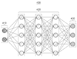
뉴럴 네트워크(neural network)(400)는 딥 뉴럴 네트워크(DNN, deep neural network)의 예시에 해당할 수 있다. DNN은 완전 연결 네트워크(fully connected network), 딥 컨볼루셔널 네트워크(deep convolutional network) 및 리커런트 뉴럴 네트워크(recurrent neural network) 등을 포함할 수 있다. 뉴럴 네트워크(400)는 딥 러닝에 기반하여 비선형적 관계에 있는 입력 데이터 및 출력 데이터를 서로 매핑함으로써 이미지의 해상도 증가를 수행할 수 있다. 딥 러닝은 빅 데이터 세트로부터 이미지 처리와 같은 문제를 해결하기 위한 기계 학습 기법으로 지도식(supervised) 또는 비지도식(unsupervised) 학습을 통해 입력 데이터 및 출력 데이터를 서로 매핑할 수 있다.The
도 4를 참조하면, 뉴럴 네트워크(400)는 입력 레이어(410), 히든 레이어(420) 및 출력 레이어(430)를 포함한다. 입력 레이어(410), 히든 레이어(420) 및 출력 레이어(430)는 각각 복수의 인공 노드들을 포함한다.Referring to FIG. 4, the
도 6에는 설명의 편의를 위해 히든 레이어(420)가 3개의 레이어를 포함하는 것으로 도시되었나, 히든 레이어(420)는 다양한 수의 레이어들을 포함할 수 있다. 또한, 도 6에는 뉴럴 네트워크(400)는 입력 데이터를 수신하기 위한 별도의 입력 레이어를 포함하는 것으로 도시되었으나, 입력 데이터가 히든 레이어(420)에 직접 입력될 수 있다. 뉴럴 네트워크(400)에서 출력 레이어(430)를 제외한 레이어들의 인공 노드들은 출력 신호를 전송하기 위한 링크들을 통해 다음 레이어의 인공 노드들과 연결될 수 있다. 링크들의 수는 다음 레이어에 포함된 인공 노드들의 수에 대응할 수 있다.6 illustrates that the
히든 레이어(420)에 포함된 각각의 인공 노드에는 이전 레이어에 포함된 인공 노드들의 가중된 입력들(weighted inputs)에 관한 활성 함수(activation function)의 출력이 입력될 수 있다. 가중된 입력은 이전 레이어에 포함된 인공 노드들의 입력에 가중치(weight)가 곱해진 것이다. 가중치는 뉴럴 네트워크(400)의 파라미터로 지칭될 수 있다. 활성 함수는 시그모이드(sigmoid), 하이퍼볼릭 탄젠트(hyperbolic tangent; tanh) 및 렐루(rectified linear unit; ReLU)를 포함할 수 있고, 활성 함수에 의해 뉴럴 네트워크(400)에 비선형성이 형성될 수 있다. 출력 레이어(430)에 포함된 각각의 인공 노드에는 이전 레이어에 포함된 인공 노드들의 가중된 입력들이 입력될 수 있다. 임의의 레이어로부터 다음 레이어로 가중된 데이터가 입력되는 과정을 전파(propagation)라고 나타낼 수 있다. 참고로, 뉴럴 네트워크(400)는 컨볼루션 필터링을 위해 구성된 컨볼루션 레이어를 포함할 수도 있다. 예를 들어, 장치는 이전 레이어로부터 컨볼루션 레이어로 임의의 정보를 전파할 수 있고, 전파된 정보에 대해 컨볼루션 필터링을 수행하며, 컨볼루션 필터링 결과를 그 다음 레이어로 전파할 수 있다.An output of an activation function regarding weighted inputs of artificial nodes included in a previous layer may be input to each artificial node included in the hidden
위에서는 해상도 증가 모델의 예시로서, 뉴럴 네트워크(400)를 설명하였으나, 해상도 증가 모델을 뉴럴 네트워크(400)로 한정하는 것은 아니다.Although the
도 5 및 도 6은 일 실시예에 따른 해상도 증가 모델이 GAN 구조로 구현된 예시를 설명한다.5 and 6 illustrate an example in which a resolution increasing model according to an embodiment is implemented in a GAN structure.
GAN(Generative Adversarial Network) 구조는 해당 구조의 특징 및 적대적 손실(adversarial loss)로 인하여 실제 같은(realistic) 이미지를 결과로서 출력할 수 있다. 다만, GAN 구조로 된 해상도 증가 모델은 출력가능한 매니폴드(manifold)들 중 하나를 선택함으로써 분류기(discriminator)를 속일 수 있는 출력을 생성하는 것으로서, 그럴 듯한(plausible) 고해상도 출력을 생성할 수 있다. 일 실시예에 따른 해상도 증가 모델은 GAN 구조로서 생성기 모델(generator model) 및 분류기 모델(discriminator)을 포함할 수 있다. 도 5는 GAN 구조로 된 해상도 증가 모델의 트레이닝 과정을 설명하고, 도 6은 트레이닝 완료 후 해상도 증가 모델을 이용한 고해상도 데이터 출력을 설명한다.The Generative Adversarial Network (GAN) structure may output a realistic image as a result due to the characteristics of the structure and adversarial loss. However, the GAN-structured resolution increase model generates an output that can fool a discriminator by selecting one of the outputable manifolds, and can generate a plausible high-resolution output. The resolution increasing model according to an embodiment may include a generator model and a discriminator as a GAN structure. 5 illustrates a training process of a resolution increasing model having a GAN structure, and FIG. 6 illustrates output of high resolution data using a resolution increasing model after training is completed.
도 5에 도시된 바와 같이, 트레이닝 장치는 원본 레이더 원시 데이터(501)로부터 데이터를 선별 동작(511)을 수행할 수 있다. 예를 들어, 트레이닝 장치는 원본 레이더 원시 데이터(501) 중 각 반복(iteration)에 사용할 임의의 차원(예를 들어, 각도 차원)에 대한 고해상도 데이터 및 저해상도 데이터를 선별할 수 있다. 예를 들어, 트레이닝 장치는 원본 레이더 원시 데이터(501)에서 일부 데이터를 추출하여 저해상도 데이터를 생성하고, 보다 많은 데이터를 추출하여 고해상도 데이터를 생성할 수 있다. 원본 레이더 원시 데이터(501)는 실제(practical) 레이더 데이터 처리 장치에 실장되는 레이더 센서보다 높은 성능의 레이더 센서를 통해 수집된 데이터일 수 있다.As shown in FIG. 5, the training apparatus may perform a
트레이닝 장치는 선별된 고해상도 데이터에 대해 고해상도 전처리 동작(513)을 수행할 수 있다. 거리-각도 맵에 대한 고해상도 전처리 동작(513)은 거리 FFT(range FFT), MUSIC(MUlti SIgnal Classification), DBF(digital beam forming), 및 비동조 적분(non-coherent integration)을 포함할 수 있다. 거리-속도 맵에 대한 고해상도 전처리 동작(513)은 거리 FFT, 속도 FFT, 및 비동조 적분을 포함할 수 있다. 또한, 유사하게, 속도-각도 맵에 대한 고해상도 전처리 동작(513)은 속도 FFT, MUSIC, DBF, 및 비동조 적분을 포함할 수 있다. 다만, 이로 한정하는 것은 아니고, 고해상도 전처리 동작(513)은 거리, 각도, 속도 중 하나 또는 둘 이상의 차원에 대한 해상도를 증가시킬 수도 있다. 트레이닝 장치는 선별된 저해상도 데이터에 대해서 저해상도 전처리 동작(512)을 수행할 수 있다. 저해상도 전처리 동작(512)은 거리 FFT, 및 DBF를 포함할 수 있다.The training apparatus may perform a high-
상술한 고해상도 전처리 동작(513)의 결과로서, 트레이닝 장치는 참값(GT, ground truth) 데이터를 트레이닝 참값(561)으로서 생성할 수 있다. 저해상도 전처리 동작(512)의 결과로서 트레이닝 장치는 저해상도 트레이닝 입력(562)을 생성할 수 있다. 또한, 트레이닝 장치는 부가 입력으로서 MUSIC 결과(580)도 생성할 수 있다. 다만, 부가 입력을 MUSIC 결과(580)로 한정하는 것은 아니고, 레이더의 도래각을 추정하는 다른 기법의 결과일 수도 있다. 도 5에서 고해상도 트레이닝 참값(561) 및 저해상도 트레이닝 입력(562)은 거리-각도 맵 포맷의 레이더 스캔 이미지일 수 있다.As a result of the high-
일 실시예에 따른 트레이닝 장치는 임시 고해상도 출력(570), 고해상도 트레이닝 참값(561), 및 서브스페이스 타입 기반 추정 기법에 기초하여 추정된 도래각 정보로부터 분류기 모델(550)에 의해 출력된 결과에 기초하여, 생성기 모델(540) 및 분류기 모델(550)을 트레이닝시킬 수 있다. 예를 들어, 서브스페이스 타입 기반 추정 기법은 MUSIC 알고리즘일 수 있고, MUSIC 결과값은 도래각 정보일 수 있다. 생성기 모델(540) 및 분류기 모델(550)은 도 4에서 상술한 바와 같은 구조로 구현될 수 있으나, 이로 한정하는 것은 아니다.The training apparatus according to an embodiment is based on the result output by the
예를 들어, 트레이닝 장치는 생성기 모델(540)을 이용하여 저해상도 트레이닝 입력(562) 및 참조 데이터베이스(590)로부터 임시 고해상도 출력(570)을 생성할 수 있다. 예를 들어, 트레이닝 장치는 저해상도 트레이닝 입력(562) 및 참조 데이터베이스(590)를 생성기 모델(540)의 입력 레이어 및/또는 중간 레이어에 입력하고, 생성기 모델(540)에 포함된 복수의 노드들을 포함하는 레이어들로 순차적으로 전파시킴으로써 임시 고해상도 출력(570)을 생성할 수 있다. 생성기 모델(540) 내에서 데이터의 전파 과정은 도 4에서 상술한 바와 유사하게 수행될 수 있다. 트레이닝 장치는 생성기 모델(540)에 의해 출력된 임시 고해상도 출력(570), 고해상도 트레이닝 참값(561), 및 서브스페이스 타입 기반 추정 기법에 기초하여 추정된 도래각 정보를 분류기 모델(550)에 입력할 수 있다. For example, the training apparatus may generate a temporary high-
트레이닝 장치는 분류기 모델(550)을 이용하여 임시 고해상도 출력(570), 고해상도 트레이닝 참값(561), 및 서브스페이스 타입 기반 추정 기법에 기초하여 추정된 도래각 정보로부터 진위 정보를 출력할 수 있다. 진위 정보는 생성기 모델(540)에 의해 출력된 임시 고해상도 출력(570)이 기준 참값인 고해상도 트레이닝 참값(561)에 비해 진짜(real)인지 가짜(fake)인지 여부를 지시하는 정보일 수 있다. 트레이닝 장치는 진위 정보에 기초하여 적대적 손실(Adversarial loss)을 산출하고, 적대적 손실에 기초하여 생성기 모델(540) 및 분류기 모델(550)을 트레이닝시킬 수 있다. 트레이닝 장치는 생성기 모델(540) 및 분류기 모델(550) 중 한 모델만 트레이닝시키거나, 두 모델을 동시에 트레이닝시키거나, 두 모델을 각각 순차적으로 트레이닝시킬 수 있다.The training apparatus may output authenticity information from the temporary high-
트레이닝 장치는 트레이닝이 완료된 경우에 응답하여, 해상도 증가 모델로부터 분류기 모델(550)을 제거할 수 있다.The training apparatus may remove the
여기서, 트레이닝 과정에서 사용되는 부가 입력(additional input)인 MUSIC 결과(580)는 도미넌트(dominant)한 신호(signal)들의 위치를 지시하므로, 생성기 모델(540)이 도미넌트한 신호들의 위치와 무관하게 임시 고해상도 출력(570)을 생성하게 될 경우, 분류기 모델(550)이 해당 출력을 쉽게 가짜라고 판별할 수 있다. 따라서, 도 5에 따라 트레이닝된 생성기 모델(540)은, 일 실시예에 따른 해상도 증가 모델로서, 분류기 모델(550)을 속이기(fooling) 위해서는, MUSIC과 같이 정확하게 예측된 도래각 정보 및 더 많은 안테나 데이터의 DBF가 표현할 수 있는 풍부한 정보가 모두 표현되는 출력 데이터를 생성하게 된다.Here, since the
도 6에 도시된 바와 같이 GAN 구조에서 트레이닝이 완료된 후, 해상도 증가 모델에서는 분류기 모델이 제거될 수 있다.As illustrated in FIG. 6, after training is completed in the GAN structure, the classifier model may be removed from the resolution increasing model.
일 실시예에 따른 레이더 데이터 처리 장치는 레이더 신호의 송신 및 수신에 기초하여 레이더 센서에 의해 레이더 원시 데이터(601)를 생성할 수 있다. 레이더 데이터 처리 장치는 생성된 레이더 원시 데이터(601)에 대해 전처리 동작(612)을 수행할 수 있다. 전처리 동작(612)은 거리 FFT 동작 및 DBF 동작을 포함할 수 있으나, 이로 한정하는 것은 아니다. 레이더 데이터 처리 장치는 전처리 동작(612)의 결과로서 입력 레이더 데이터(662)를 생성할 수 있다. 예시적으로 입력 레이더 데이터(662)는 거리-각도 맵의 포맷으로 된 레이더 스캔 이미지일 수 있다. 레이더 데이터 처리 장치는 트레이닝된 생성기 모델(640)을 포함하는 해상도 증가 모델을 이용하여, 레이더 원시 데이터(601)를 전처리함으로써 생성된 입력 레이더 데이터(662)와 함께 참조 데이터베이스(690)의 참조 데이터로부터 고해상도 출력 레이더 데이터(670)를 생성할 수 있다. 생성된 고해상도 출력 레이더 데이터(670)는 입력 레이더 데이터(660)에 비해 고해상도를 가질 수 있다. 참고로, 참조 데이터는 입력 레이더 데이터(660)보다 고해상도의 데이터일 수 있으나, 이로 한정하는 것은 아니다. 또한, 참조 데이터의 해상도는 출력 레이더 데이터의 해상도와 동일할 수 있으나, 이로 한정하는 것은 아니고, 더 높거나 낮을 수도 있다.The radar data processing apparatus according to an embodiment may generate the radar
도 7 및 도 8은 일 실시예에 따른 레이더 데이터 처리 장치가 참조 데이터를 해상도 증가 모델의 적용하는 예시를 설명한다.7 and 8 illustrate examples in which a radar data processing apparatus according to an embodiment applies reference data to a resolution increase model.
도 7 및 도 8은 일 실시예에 따른 레이더 데이터 처리 장치는 상술한 바와 같이 입력 레이더 데이터로부터 입력 레이더 이미지를 생성한 예시를 설명한다. 다만, 이로 한정하는 것은 아니고, 레이더 데이터 처리 장치는 입력 레이더 데이터 자체 또는 입력 레이더 데이터로부터 변환된 다른 포맷의 데이터를 해상도 증가 모델에 제공할 수도 있다. 도 7에 도시된 입력 레이더 이미지 및 참조 레이더 이미지는 거리-각도 맵으로서, 임의의 거리 및 임의의 각도에 객체가 존재할 확률을 지시할 수 있다.7 and 8 illustrate examples in which the radar data processing apparatus according to an embodiment generates an input radar image from input radar data as described above. However, the present invention is not limited thereto, and the radar data processing apparatus may provide the input radar data itself or data in another format converted from the input radar data to the resolution increasing model. The input radar image and the reference radar image shown in FIG. 7 are distance-angle maps, and may indicate a probability that an object exists at an arbitrary distance and at an arbitrary angle.
도 7에서 레이더 데이터 처리 장치는 참조 레이더 이미지(791)를 참조 데이터로서 입력 레이더 이미지(701)에 연결(concatenate)하여 입력 데이터(710)를 생성할 수 있다. 참조 레이더 이미지(791)는 예를 들어, 입력 레이더 이미지(701)의 해상도보다 높은 해상도를 가질 수 있으나, 이로 한정하는 것은 아니다. 아울러, 입력 데이터(710)는 입력 레이더 이미지(701) 및 참조 레이더 이미지(791)가 단순히(simply) 연결된(concatenated) 데이터로 설명되었으나, 이로 한정하는 것은 아니고, 임의의 다른 통합 연산(merging operation)을 통해 생성되는 단일 데이터(예를 들어, 행렬 포맷 또는 벡터 포맷)일 수도 있다.In FIG. 7, the radar data processing apparatus may generate
레이더 데이터 처리 장치는 입력 데이터(710)로부터 해상도 증가 모델(740)을 이용하여 출력 레이더 데이터로서 출력 레이더 이미지를 생성할 수 있다. 도 7에서 해상도 증가 모델(740)은 하나 이상의 컨볼루션 레이어(Convolutional layer 1, Convolutional layer 2) 및 하나 이상의 풀링 레이어(Pooling1, Pooling2)를 포함하는 것으로 도시되었으나, 이로 한정하는 것은 아니다.The radar data processing apparatus may generate an output radar image as output radar data by using the
도 8에서 레이더 데이터 처리 장치는 참조 데이터로서 참조 특징 데이터(895)를 이용할 수 있다. 예를 들어, 참조 특징 데이터(895)는 참조 레이더 이미지로부터 특징 추출 모델을 이용하여 추출된 특징 데이터일 수 있다. 특징 추출 모델은 데이터(예를 들어, 이미지)의 특징을 추출하도록 설계된 모델(예를 들어, 뉴럴 네트워크)일 수 있다. 일 실시예에 따르면 레이더 데이터 처리 장치는 입력 레이더 데이터(801)로부터 해상도 증가 모델(840)의 일부 레이어(841)를 이용하여 입력 특징 데이터(805)를 추출할 수 있다. 도 8에서 일부 레이어(841)는 하나 이상의 컨볼루션 레이어(Convolutional layer 1) 및 풀링 레이어(Pooling1)를 포함하는 것으로 도시되었으나, 이로 한정하는 것은 아니다.In FIG. 8, the radar data processing apparatus may use
레이더 데이터 처리 장치는 입력 특징 데이터 및 참조 특징 데이터(895)로부터 해상도 증가 모델(840)의 다른 일부 레이어(842)를 이용하여 출력 레이더 데이터를 생성할 수 있다. 예를 들어, 레이더 데이터 처리 장치는 입력 레이더 데이터(801)를 획득하기 전에 저장된 참조 특징 데이터(895)를 입력 특징 데이터에 연결(concatenate)할 수 있다. 레이더 데이터 처리 장치는 참조 특징 데이터(895) 및 입력 특징 데이터가 연결된 데이터로부터 다른 일부 레이어(842)를 이용하여 출력 레이더 데이터를 생성할 수 있다. 도 8에서 다른 일부 레이어(842)는 하나 이상의 풀링 레이어(Pooling2)를 포함하는 것으로 도시되었으나, 이로 한정하는 것은 아니다. 아울러, 참조 특징 데이터(895) 및 입력 특징 데이터(805)는 추상화 레벨이 동일할 수 있으나, 이로 한정하는 것은 아니고 다를 수도 있다. 예를 들어, 참조 특징 데이터(895)를 추출하기 위해 참조 레이더 스캔 이미지에 적용된 컨볼루션 레이어의 개수와 입력 특징 데이터(805)를 추출하기 위해 입력 레이더 스캔 이미지에 적용된 컨볼루션 레이어의 개수는 동일하거나 다를 수 있다.The radar data processing apparatus may generate output radar data from the input feature data and the
따라서 레이더 데이터 처리 장치는 참조 데이터베이스로서 참조 레이더 스캔 이미지 원본을 유지하는 대신, 높은 레벨(high-level)의 디테일(detail)이나 텍스쳐(texture)를 표현할 수 있는 특징 데이터를 유지할 수 있다. 특징 데이터는 데이터(예를 들어, 이미지)가 추상화된 데이터로서, 예를 들어, 특징 벡터 형태일 수 있다. 특징 데이터를 포함하는 참조 데이터베이스의 메모리 크기는 절감될 수 있다. 참조 특징 데이터(895)는 입력 레이더 데이터가 획득되기 전에 참조 데이터베이스에 저장될 수도 있다.Therefore, the radar data processing apparatus may maintain feature data capable of expressing high-level detail or texture, instead of maintaining the original reference radar scan image as a reference database. The feature data is data from which data (eg, an image) is abstracted, and may be, for example, in the form of a feature vector. The memory size of the reference database including feature data can be reduced. The
도 9는 일 실시예에 따른 고성능 레이더 센서를 이용한 참조 데이터 수집을 설명한다.9 illustrates collection of reference data using a high-performance radar sensor according to an embodiment.
일 실시예에 따르면 참조 데이터는, 입력 레이더 데이터를 획득하기 이전에 레이더 센서보다 높은 해상도의 다른 레이더 센서에 의해 획득된 레이더 데이터일 수 있다.According to an embodiment, the reference data may be radar data obtained by another radar sensor having a higher resolution than a radar sensor before obtaining the input radar data.
예를 들어, 참조 데이터 수집 장치(920)는 고해상도 데이터 획득부(921) 및 참조 데이터 선별부(922)를 포함할 수 있다. 고해상도 데이터 획득부(921)는 고해상도로 레이더 데이터를 생성할 수 있는 고성능 레이더 센서를 포함할 수 있다. 고성능 레이더 센서는 하이엔드(high-end)의 하드웨어일 수 있다. 참조 데이터 선별부(922)는 고해상도 레이더 데이터 획득부(911)를 통해 수집된 고해상도 레이더 데이터를 처리 및 선별함으로써 참조 데이터베이스(990)를 생성할 수 있다. 예를 들어, 참조 데이터 선별부(922)는 장치 주변 환경에 따라 고해상도 레이더 데이터를 분류하여 참조 데이터로 저장할 수 있다. 다른 예를 들어, 참조 데이터 선별부(922)는 레이더 센서의 이동 방향에 따라 고해상도 레이더 데이터를 분류할 수도 있다.For example, the reference
레이더 데이터 처리 장치(910)는 레이더 데이터 획득부(911), 해상도 증가 모델(912), 및 레이더 데이터 처리부(913)를 포함할 수 있다. 해상도 증가 모델(912) 및 레이더 데이터 처리부(913)는 앞서 설명하였으므로 설명을 생략한다. 레이더 데이터 획득부(911)는 고해상도 레이더 획득부에 비해 낮은 성능의 레이더 센서를 포함할 수 있다. 레이더 데이터 처리 장치(910)의 메모리에는 참조 데이터 수집 장치(920)에 의해 생성된 참조 데이터베이스(990)가 이식될 수 있다. 따라서 레이더 데이터 처리 장치(910)는 상대적으로 저가의 레이더 센서와 함께 고해상도의 레이더 데이터에 관한 참조 데이터베이스(990)를 포함할 수 있다. 레이더 데이터 처리 장치(910)는 레이더 데이터 획득부(911)를 통해 획득된 저해상도 레이더 데이터와 함께 고해상도의 참조 데이터베이스(990)로부터 해상도 증가 모델(912)을 이용하여 고해상도의 출력 레이더 데이터를 생성할 수 있다. 레이더 데이터 처리 장치(910)는 참조 데이터의 고주파수 성분(high frequency component)를 통해 저해상도의 입력 레이더 데이터로부터 고주파수 성분을 복원할 수 있다. 참고로, 참조 데이터는, 레이더 센서와 적어도 일부 중첩되는 시야각을 가지는 다른 레이더 센서에 의해 획득된 레이더 데이터로서, 예를 들어, 고해상도 데이터 획득부(921) 및 레이더 데이터 획득부(911)의 시야각은 동일할 수 있다. 다만, 이로 한정하는 것은 아니다.The radar
일 실시예에 따른 레이더 데이터 처리 장치(910)는 레이더 데이터 처리 장치(910)의 주변 환경을 식별(identify)할 수 있다. 주변 환경은 레이더 데이터 처리 장치(910)의 주변의 환경에 관한 정보로서, 예를 들어, 레이더 데이터 처리 장치(910)가 모바일 어플리케이션 또는 차량으로 구현된 경우 이동 환경 정보(movement environment information)일 수 있다. 예를 들어, 레이더 데이터 처리 장치(910)가 차량에 장착된 경우, 레이더 데이터 처리 장치(910)는 차량의 주행 환경을 상술한 이동 환경 정보로서 식별할 수 있다. 레이더 데이터 처리 장치(910)는 고속도로 주행 상태, 시내도로 주행 상태, 고가도로 주행 상태, 및 터널 주행 상태 등을 식별할 수 있다. 참고로, 레이더 데이터 처리 장치(910)는 레이더 데이터를 이용하여 이동 환경 정보를 식별할 수도 있으나, 이로 한정하는 것은 아니고, 측위 정보(localization)(예를 들어, GPS 정보, 가속도 정보 등) 및 지리적 맵 데이터에 기초하여 차량의 주행 환경을 식별할 수도 있다.The radar
앞서 설명한 바와 같이, 참조 데이터 선별부(922)는 이동 환경 정보 별로 참조 데이터를 구별하여 참조 데이터베이스(990)를 생성할 수 있다. 레이더 데이터 처리 장치(910)는 참조 데이터베이스(990)에서 식별된 주변 환경에 대응하는 참조 데이터를 검색할 수 있다. 레이더 데이터 처리 장치(910)는 참조 데이터베이스(990)로부터 식별된 주변 환경에 대응하는 참조 데이터를 획득할 수 있다. 예를 들어, 현재 차량이 고속도로 주행 상태인 것으로 식별되는 경우, 레이더 데이터 처리 장치(910)는 고속도로 주행 상태로 선별된 참조 데이터를 로딩하여 입력 레이더 데이터와 함께 해상도 증가 모델(912)에 제공할 수 있다.As described above, the reference
도 10은 일 실시예에 따른 복수의 레이더 센서들을 이용한 참조 데이터 수집을 설명한다.10 illustrates collection of reference data using a plurality of radar sensors according to an embodiment.
일 실시예에 따르면 복수의 레이더 센서들(1011, 1012, 1013)이 차량의 여러 부위에 설치될 수 있고, 복수의 레이더 센서들(1011, 1012, 1013)에 의해 센싱된 정보를 기초로 레이더 데이터 처리 장치(1000)가 차량의 전방위(all direction)에 대한 타겟 지점까지의 거리, 방향(예를 들어, 스티어링 각도), 및 상대 속도를 상술한 바와 같이 계산할 수 있다. 레이더 데이터 처리 장치(1000)는 예를 들어, 차량에 탑재될 수 있다. 차량은 레이더 센서들(1011, 1012, 1013)에 의해 수집된 정보에 기초하여 획득된 정보를 이용하여, 주행에 도움이 되는 다양한 기능(예를 들어, ACC(Adaptive Cruise Control), BSD(Blind Spot Detection), 및 LCA(lane change assistance) 등)을 제공할 수 있다.According to an embodiment, a plurality of
도 10에 도시된 바와 같이 하나의 이동체에 장착된 복수의 레이더 센서들(1011, 1012, 1013)은 동일 또는 유사한 맥락의 장면을 센싱할 수 있다. 예를 들어, 복수의 레이더 센서들(1011, 1012, 1013)의 각각의 시야각이 중첩되지 않더라도, 각 레이더 센서들(1011, 1012, 1013)은 연속된 외부 장면(1090)의 일부를 센싱할 수 있다. 예를 들어, 제1 레이더 센서(1011)는 외부 장면(1090)을 제1 시야각 범위(1091)로 센싱하고, 제2 레이더 센서(1012)는 동일한 외부 장면(1090)을 제2 시야각 범위(1092)로 센싱하며, 제3 레이더 센서(1013)는 동일한 외부 장면(1090)을 제3 시야각 범위(1093)로 센싱할 수 있다. 제1 시야각 범위(1091) 내지 제3 시야각 범위(1093)가 서로 중첩되지 않더라도 복수의 레이더 센서들(1011, 1012, 1013)이 이동체의 이동에 의존적일 수 있다. 다시 말해, 단일 이동체(예를 들어, 모바일 단말 또는 차량)에 장착된 복수의 레이더 센서들(1011, 1012, 1013)에 의해 센싱되는 레이더 데이터는 장면 맥락에 의존적일 수 있다. 상술한 바와 같이, 시야각이 겹치지 않는 다른 레이더 센서에 의해 획득된 레이더 데이터로 당해 레이더 센서에 의한 레이더 데이터의 해상도를 증가시키는데 사용될 수 있다.As shown in FIG. 10, a plurality of
예를 들어, 복수의 레이더 센서들(1011, 1012, 1013) 중 한 레이더 센서가 입력 레이더 데이터를 획득할 수 있고, 다른 레이더 센서가 추가 레이더 데이터를 획득할 수 있다. 레이더 데이터를 처리하는 장치는 추가 레이더 데이터로부터 참조 데이터를 생성할 수 있다. 레이더 센서 및 다른 레이더 센서는 동일한 이동체(moving object)에 장착될 수 있다.For example, one of the plurality of
참고로, 복수의 레이더 센서들(1011, 1012, 1013)의 각각은 자체적으로 프로세서 및 참조 데이터베이스를 포함할 수 있고, 서로 데이터를 교환할 수 있다. 복수의 레이더 센서들(1011, 1012, 1013) 중 한 레이더 센서는 레이더 데이터를 전처리한 결과 및/또는 레이더 데이터로부터 추출된 레이더 특징 데이터를 다른 레이더 센서로 전달할 수도 있다. 레이더 센서는 레이더 데이터를 생성하는 경우에 응답하여 지연 없이 즉시 데이터를 교환할 수 있으나, 이로 한정하는 것은 아니고, 시간차를 두고 데이터를 교환할 수도 있다.For reference, each of the plurality of
또한, 레이더 데이터 처리 장치(1000)는 복수의 레이더 센서들(1011, 1012, 1013)의 각각에 의해 수집된 레이더 데이터를 중앙 프로세서(1020)를 통해 처리할 수도 있다. 예를 들어, 레이더 데이터 처리 장치(1000)는 자율주행 차량과 같이 서로 다른 종류의 센서들을 여러 개 사용하는 플랫폼으로 구현될 수 있다. 중앙 프로세서(1020)는 여러 센서들의 데이터를 취합하여 처리하고, 그 결과에 기초하여 차체를 제어할 수 있다. 중앙 프로세서(1020)가 복수의 레이더 센서들(1011, 1012, 1013)의 각각에서 수집된 레이더 데이터 및 참조 데이터로부터 해상도 증가 모델을 이용하여 각 레이더 센서의 시야각에 대한 고해상도의 출력 레이더 데이터를 생성할 수 있다. 각 레이더 센서의 레이더 데이터가 중앙 프로세서(1020)에 의해 처리될 경우, 데이터 전송의 오버헤드가 감소되고, 정확도가 개선될 수 있다. 레이더 센서는 레이더 데이터로부터 레이더 특징 데이터를 추출하여 중앙 프로세서(1020)로 전달함으로써 데이터 전송 속도를 개선할 수도 있다.In addition, the radar
레이더 데이터 처리 장치(1000)는 각 레이더 센서에 대해 개별 레이더 센서에 대응하는 참조 데이터베이스 및 다른 레이더 센서에 의해 획득된 참조 데이터를 이용하여 보다 사실적인 고해상도의 출력 레이더 데이터를 생성할 수 있다.The radar
도 9에서는 센서 레벨에서 개별 레이더 센서가 참조 데이터베이스를 포함하고, 레이더 센서가 해상도 증가 동작을 수행하여 고해상도의 레이더 데이터를 출력하는 동작을 설명하였으나, 아래에서는 비슷한 성능의 다른 레이더 센서에 의해 획득된 레이더 데이터를 참조 데이터로서 활용하는 예시를 설명한다. 예를 들어, 도 11은 서로 다른 용도의 레이더 센서들(1011, 1012, 1013) 간의 데이터 교환을 설명하고, 도 12는 인접한 시간 프레임들에서 동일한 장면 또는 객체를 센싱한 레이더 센서들(1011, 1012, 1013) 간의 데이터 교환을 설명하며, 도 13은 외부 서버로부터 참조 데이터를 검색하는 구성을 설명한다.In FIG. 9, an operation in which an individual radar sensor includes a reference database at the sensor level and the radar sensor performs a resolution increase operation to output high-resolution radar data is described, but below is a radar obtained by another radar sensor with similar performance. An example of using data as reference data will be described. For example, FIG. 11 illustrates data exchange between
도 11은 일 실시예에 따른 복수의 레이더 센서들 중 시야각을 공유하는 레이더 센서들 간의 참조 데이터를 설명한다.11 illustrates reference data between radar sensors sharing a viewing angle among a plurality of radar sensors according to an exemplary embodiment.
일 실시예에 따르면 임의의 레이더 데이터와 유사한 컨텐츠(contents)를 포함하는 다른 레이더 데이터는, 해당 레이더 데이터의 해상도를 증가시키는 참조 데이터로서 유용할 수 있다.According to an embodiment, other radar data including contents similar to arbitrary radar data may be useful as reference data for increasing the resolution of the corresponding radar data.
예를 들어, 도 11에 도시된 레이더 데이터 처리 장치는 차량에 장착될 수 있고, 복수의 레이더 센서들을 포함할 수 있다. 복수의 레이더 센서들은 넓은 센싱 범위를 커버하도록 배치될 수 있고, 예를 들어, 360도의 전방위를 커버하도록 배치될 수 있다. 예를 들어, 제1 레이더 센서(1111) 및 제2 레이더 센서(1112)는 전방 센싱 범위(1191, 1192)를 커버하고, 제3 레이더 센서(1113), 제4 레이더 센서(1114), 제6 레이더 센서(1116), 및 제7 레이더 센서(1117)는 측면 센싱 범위(1193, 1194, 1196, 1197)를 커버하며, 제5 레이더 센서(1115)는 후방 센싱 범위(1195)를 커버할 수 있다.For example, the radar data processing apparatus shown in FIG. 11 may be mounted on a vehicle and may include a plurality of radar sensors. The plurality of radar sensors may be disposed to cover a wide sensing range, for example, may be disposed to cover all directions of 360 degrees. For example, the
각 레이더 센서는 다양한 시야각 및 센싱 거리를 가질 수 있다. 레이더 센서의 사양은 이동체(예를 들어, 차량)의 장착 위치에 따라 결정될 수 있다. 예를 들어, 이동체의 전면에 장착되는 제1 레이더 센서(1111)는 LRR (Long Range Radar)로서 좁은 시야각과 낮은 거리 해상도(예를 들어, 큰 거리 분해능 단위), 및 낮은 각 해상도(예를 들어, 큰 각도 분해능 단위)를 가질 수 있으나, 먼 탐지 거리 및 높은 최대 탐지 가능 속도(maximum detectable velocity)를 가질 수 있다. 예를 들어, 다른 타입의 레이더 센서의 최대 탐지 가능 속도가 -100km/h 부터 100km/h까지라면, LRR 타입의 레이더 센서의 최대 탐지 가능 속도는 -300km/h부터 200km/h까지일 수 있다. LRR은 ACC (Adaptive Cruise Control)에 사용될 수 있다. 이동체의 측면에 장착되는 제3 레이더 센서(1113), 제4 레이더 센서(1114), 제6 레이더 센서(1116), 및 제7 레이더 센서(1117)는 MRR (Middle Range Radar)로서 중간 정도의 해상도 및 시야각을 가질 수 있다. 이동체의 전면 및 후면에 각각 장착되는 제2 레이더 센서(1112) 및 제5 레이더 센서(1115)는 SRR (Short Range Radar)로서, 짧은 탐지 거리를 갖지만 넓은 시야각과 높은 거리 해상도 및 높은 각 해상도를 가질 수 있다. MRR 및 SRR은 차량의 정지 및 진행(Stop& Go), ACC 보조, LCA (Lane Change Assist), BSD (Blind Spot Detection), 및 백업 레이더(Back-up radar)로서 사용될 수 있다. Each radar sensor can have a variety of viewing angles and sensing distances. The specifications of the radar sensor may be determined according to the mounting position of the moving object (eg, vehicle). For example, the
일 실시예에 따른 레이더 데이터 처리 장치는 서로 다른 사양의 레이더 센서에 의해 획득된 레이더 데이터를 다른 레이더 센서와 교환시키거나 중앙 프로세서가 복수의 레이더 데이터를 수집함으로써, 각 레이더 데이터의 해상도를 증가시키는데 사용할 수 있다. 도 11에 도시된 바와 같이 360도의 전방위를 센싱 가능하게 배치된 레이더 센서들의 각각은 다른 레이더 센서와 적어도 일부 센싱 영역 및/또는 시야각을 공유할 수 있다. 제1 레이더 센서(1111)는 제2 레이더 센서(1112)와 제1 중첩 센싱 영역(1181)을 공유할 수 있다. 제2 레이더 센서(1112)는 제3 레이더 센서(1113)와 제2 중첩 센싱 영역(1182)을 공유할 수 있다. 제3 레이더 센서(1113)는 제4 레이더 센서(1114)와 제3 중첩 센싱 영역(1183)을 공유할 수 있다. 유사하게, 제6 레이더 센서(1116)는 제7 레이더 센서(1117)와 제4 중첩 센싱 영역(1184)을 공유하고, 제7 레이더 센서(1117)는 제2 레이더 센서(1112)와 제5 중첩 센싱 영역(1185)을 공유할 수 있다.The radar data processing apparatus according to an embodiment is used to increase the resolution of each radar data by exchanging radar data acquired by radar sensors of different specifications with other radar sensors or by a central processor collecting a plurality of radar data. I can. As illustrated in FIG. 11, each of the radar sensors arranged to sense an all-round 360 degree may share at least a partial sensing area and/or a viewing angle with other radar sensors. The
예를 들어, 레이더 데이터 처리 장치에서 임의의 레이더 센서와 적어도 일부 시야각이 오버랩되는 다른 레이더 센서가 추가 레이더 데이터를 획득할 수 있다. 레이더 데이터 처리 장치는 시야각이 오버랩되는 추가 레이더 데이터로부터 참조 데이터를 생성할 수 있다. 시야각이 오버랩되는 다른 레이더 센서에 의해 센싱된 추가 레이더 데이터는 연속된 장면 중에서도 동일한 부분 장면(partial scene)에 관한 것이므로, 레이더 데이터의 해상도를 증가시키기 위한 참조 데이터로서의 가치가 높을 수 있다. 참고로, 도 10에서는 레이더 센서 각각이 참조 데이터베이스를 포함하는 예시를 설명하였으나, 이로 한정하는 것은 아니고, 각 레이더 센서는 기 저장된 참조 데이터베이스 없이, 다른 레이더 센서로부터 전달되는 레이더 데이터를 참조 데이터로서 활용할 수도 있다. 다른 레이더 센서에 의해 획득되는 참조 데이터는 레이더 원시 데이터 포맷으로 저장 및/또는 전달될 수 있으나, 이로 한정하는 것은 아니고 레이더 원시 데이터로부터 고레벨 특징 데이터의 형태로 추출되어 전달될 수도 있다.For example, in the radar data processing apparatus, an arbitrary radar sensor and another radar sensor in which at least some of the viewing angles overlap may acquire additional radar data. The radar data processing apparatus may generate reference data from additional radar data whose viewing angles overlap. Since the additional radar data sensed by other radar sensors with overlapping viewing angles relates to the same partial scene among consecutive scenes, the value as reference data for increasing the resolution of the radar data may be high. For reference, although an example in which each radar sensor includes a reference database is described in FIG. 10, it is not limited thereto, and each radar sensor may utilize radar data transmitted from other radar sensors as reference data without a previously stored reference database. have. Reference data acquired by other radar sensors may be stored and/or transmitted in a radar raw data format, but is not limited thereto and may be extracted and transmitted in the form of high-level feature data from the radar raw data.
도 12는 일 실시예에 따른 복수의 레이더 센서들 중 동일한 객체를 센싱한 레이더 센서들 간의 참조 데이터를 설명한다.12 illustrates reference data between radar sensors sensing the same object among a plurality of radar sensors according to an exemplary embodiment.
일 실시예에 따른 레이더 데이터 처리 장치는, 임의의 레이더 센서에 의해 획득된 입력 레이더 데이터의 해상도를 증가시키기 위해, 이전 시간 프레임에서 다른 레이더 센서에 의해 획득된 이전 레이더 데이터 중 현재 시간 프레임에서 레이더 센서의 시야각과 적어도 일부 장면이 공유되는 데이터를 이용하여 참조 데이터를 생성할 수 있다. 다시 말해, 레이더 데이터 처리 장치는 이동체(예를 들어, 차량)의 측위 정보, 이동 정보, 레이더 센서들의 배치 정보, 및 레이더 센서들의 센싱 영역에 관한 정보 중 하나 또는 둘 이상의 조합에 기초하여 현재 시간 프레임의 각 레이더 센서에 대해 이전 시간 프레임에서 동일한 부분 장면을 센싱한 다른 레이더 센서를 결정할 수 있다. 레이더 데이터 처리 장치는 다른 레이더 센서에 의해 이전 시간 프레임에서 센싱된 레이더 데이터를, 현재 시간 프레임의 해당 레이더 센서에 의한 입력 레이더 데이터의 해상도를 증가시키기 위한 참조 데이터로 이용할 수 있다.The radar data processing apparatus according to an embodiment includes a radar sensor in a current time frame among previous radar data acquired by another radar sensor in a previous time frame in order to increase the resolution of input radar data acquired by an arbitrary radar sensor. Reference data may be generated using data shared by the viewing angle of and at least some scenes. In other words, the radar data processing apparatus is based on one or a combination of two or more of positioning information of a moving object (eg, vehicle), movement information, arrangement information of radar sensors, and information on a sensing area of the radar sensors. For each radar sensor in, it is possible to determine another radar sensor that sensed the same partial scene in the previous time frame. The radar data processing apparatus may use radar data sensed in a previous time frame by another radar sensor as reference data for increasing the resolution of input radar data by a corresponding radar sensor in the current time frame.
예를 들어, 도 11에 도시된 바와 같이 레이더 센서들이 배치된 차량에 있어서, 차량이 주행하는 동안 차량의 움직임 및 시간 경과에 따라 임의의 한 레이더 센서에서 센싱됐던 영역이 다른 레이더 센서에 의해 센싱될 수 있다. 예를 들어, 차량이 직진하는 경우, 제1 레이더 센서(1211)에 의해 제1 시점(1201)에서 센싱된 장면은, 제1 시점(1201) 이후의 제2 시점(1202)에서 제2 레이더 센서(1212)에 의해 센싱될 수 있다. 이 경우, 제1 시점(1201)에서 제1 레이더 센서에 의해 센싱된 레이더 데이터는, 제2 시점(1202)에서 제2 레이더 센서에 의해 센싱된 입력 레이더 데이터의 해상도를 증가시키기 위한 참조 데이터로서 이용될 수 있다. 제1 레이더 센서(1211)가 센싱한 부분 장면은, 일정 시간(예를 들어, 짧은 시간) 경과 후 차량의 움직임에 따라 제2 레이더 센서(1212)에 의해 센싱되는 부분 장면과 중첩될 수 있다.For example, in a vehicle in which radar sensors are arranged as shown in FIG. 11, an area sensed by one radar sensor may be sensed by another radar sensor according to the movement of the vehicle and the passage of time while the vehicle is running. I can. For example, when the vehicle goes straight, the scene sensed at the
또한, 레이더 데이터 처리 장치는 이전 시간 프레임에서 다른 레이더 센서에 의해 획득된 이전 레이더 데이터 중 현재 시간 프레임에서 레이더 센서를 통해 검출된 객체를 포함하는 데이터를 이용하여 참조 데이터를 생성할 수 있다. 예를 들어, 레이더 데이터 처리 장치는 차량의 주변에 표적(1290)이 검출되는 경우에 응답하여, 차량의 측위 정보, 차량의 이동 정보, 레이더 센서들의 배치 정보, 레이더 센서들의 센싱 영역에 관한 정보, 및 표적(1290)의 이동 정보 중 하나 또는 둘 이상의 조합에 기초하여 이전 시간 프레임에서 표적(1290)을 센싱한 다른 레이더 센서를 결정할 수 있다. 예를 들어, 차량이 직진하는 경우, 제1 레이더 센서(1211)에 의해 제1 시점(1201)에서 센싱된 객체는, 제1 시점(1201) 이후의 제2 시점(1202)에서 제2 레이더 센서(1212)에 의해 센싱될 수 있다. 레이더 데이터 처리 장치는 다른 레이더 센서에 의해 이전 시간 프레임에서 센싱된 레이더 데이터를, 현재 시간 프레임의 해당 레이더 센서에 의한 입력 레이더 데이터의 해상도를 증가시키기 위한 참조 데이터로 이용할 수 있다. 따라서, 레이더 데이터 처리 장치는 동일 표적(1290)에 대해 다른 시점에서 다중 뷰(multi-view)로 센싱된 정보를 참조 데이터로 이용할 수 있다.In addition, the radar data processing apparatus may generate reference data by using data including an object detected by a radar sensor in a current time frame among previous radar data acquired by another radar sensor in a previous time frame. For example, in response to the detection of the
참고로, 도 12에서는 직진을 예로 들어 설명하였으나, 이로 한정하는 것은 아니고, 차량이 우회전, 좌회전, U턴 등과 같은 주행을 하는 경우, 같은 표적(1290) 및/또는 장면에 대하여 전방, 전측방, 후측방, 후방 등의 레이더 센서가 다른 시점에서 다른 뷰로 센싱할 수 있다.For reference, in FIG. 12 has been described as an example, but is not limited thereto, and when the vehicle is driving such as a right turn, a left turn, a U turn, etc., the
도 13은 일 실시예에 따른 레이더 데이터 처리 장치가 외부 서버로부터 참조 데이터를 검색 및 수신하는 예시를 설명한다.13 illustrates an example in which a radar data processing apparatus according to an embodiment searches for and receives reference data from an external server.
일 실시예에 따르면 레이더 데이터 처리 장치(1300)는 레이더 데이터 처리 장치(1300)의 외부 데이터베이스로부터 식별된 주변 환경에 대응하는 참조 데이터(1331)를 수신할 수 있다. 주변 환경은 도 9에서 상술하였으므로 설명을 생략한다. 레이더 데이터 처리 장치(1300)는 통신부(1340)를 통해 외부 서버(1390)와 유선 또는 무선 통신을 수립할 수 있으며, 인터넷에 접속할 수 있다. 예를 들어, 레이더 데이터 처리 장치(1300)의 프로세서(1320)는 식별된 주변 환경(예를 들어, 다리, 터널, 및 도심 등)에 대응하는 데이터(예를 들어, 레이더 스캔 이미지 및 특징 데이터 등)를 외부 서버(1390)에 요청 및/또는 외부 서버(1390)에서 검색할 수 있다. 레이더 데이터 처리 장치(1300)는 외부 서버(1390)로부터 수신된 참조 데이터(1331)를 메모리(1330)의 참조 데이터베이스에 저장할 수도 있다. 따라서 레이더 데이터 처리 장치(1300)는 레이더 데이터(예를 들어, 레이더 스캔 이미지)의 업스케일링을 위해 적합하거나 필요한 참조 데이터베이스를 주변 환경에 응답하여 적응적으로(adaptive) 웹 검색(web retrieval)을 통해 구축(build)할 수 있다. 또한, 레이더 데이터 처리 장치(1300)는 외부 서버(1390)와의 통신을 통해 참조 데이터(1331) 및 해상도 증가 모델(1332)을 업데이트할 수도 있다.According to an embodiment, the radar
센서(1310)는 상술한 레이더 센서 외에도 다양한 센서를 부가적으로 더 포함할 수도 있다. 레이더 센서 이외의 다른 종류의 센서는 아래 도 14에서 설명한다.The
도 14는 일 실시예에 따른 다양한 센서를 통해 수집된 추가 정보를 추가 참조 데이터로서 이용하는 예시를 설명한다.14 illustrates an example in which additional information collected through various sensors according to an embodiment is used as additional reference data.
일 실시예에 따르면 레이더 데이터 처리 장치는 레이더 센서 외에도 다양한 센서를 통해 추가 정보를 수집하여 참조 데이터로서 이용할 수 있다. 예를 들어, 레이더 데이터 처리 장치는 레이더 센서와 공통되는 기준 좌표계를 기준으로 정렬된 적외선 센서, 이미지 센서, 및 라이다 센서 중 적어도 하나에 기초하여 참조 데이터를 획득할 수 있다. 도 14에서는 라이다 데이터로서 라이다 이미지 맵(1491) 및 카메라 데이터로서 카메라 이미지(1492)가 참조 데이터로서 획득될 수 있다. 레이더 데이터 처리 장치는 레이더 센서, 라이다 센서, 및 카메라 센서를 캘리브레이션(calibration)함으로써, 센서들의 좌표계를 기준 좌표계로 통일할 수 있다. 레이더 데이터 처리 장치는 입력 레이더 데이터(1410)와 함께 라이다 이미지 맵(1491) 및 카메라 이미지(1492)를 해상도 증가 모델(1420)에 적용함으로써, 출력 레이더 데이터(1480)를 생성할 수 있다.According to an embodiment, the radar data processing apparatus may collect additional information through various sensors in addition to the radar sensor and use it as reference data. For example, the radar data processing apparatus may obtain reference data based on at least one of an infrared sensor, an image sensor, and a lidar sensor arranged on the basis of a reference coordinate system common to the radar sensor. In FIG. 14, a
도 15는 도 14에서 수집된 다양한 추가 정보에 기초한 객체 검출 결과를 추가 참조 데이터로서 이용하는 예시를 설명한다.15 illustrates an example of using an object detection result based on various additional information collected in FIG. 14 as additional reference data.
일 실시예에 따른 레이더 데이터 처리 장치는 앞서 도 14에서 설명된 다양한 추가 센서들에 의해 획득된 데이터로부터 추가적인 정보를 추출하여 이용할 수 있다.The radar data processing apparatus according to an embodiment may extract and use additional information from data acquired by various additional sensors described in FIG. 14 above.
예를 들어, 레이더 데이터 처리 장치는 참조 데이터로부터 객체를 검출하고 분류할 수 있다. 도 15에서는 레이더 데이터 처리 장치는 참조 데이터로서 카메라 이미지(1590)를 획득할 수 있고, 카메라 이미지(1590)로부터 객체를 검출 및 분류할 수 있다. 예를 들어, 차량의 주변에 존재하는 객체의 이미지 상의 좌표를 계산하고, 객체의 종류(예를 들어, 차량, 보행자, 신호등, 및 장애물 등)를 식별할 수 있다.For example, the radar data processing apparatus may detect and classify objects from reference data. In FIG. 15, the radar data processing apparatus may acquire a
레이더 데이터 처리 장치는 객체의 분류 결과(1591)와 함께 입력 레이더 데이터(1510) 및 참조 데이터로부터 해상도 증가 모델(1520)을 이용하여 출력 레이더 데이터(1580)를 생성할 수 있다. 앞서 도 14에서 설명한 바와 같이 센서들이 기준 좌표계로 정렬되었으므로, 레이더 데이터 이외의 정보로부터 객체 검출 및 분류 결과(1591)를 이용하여 보다 고해상도의 출력 레이더 데이터(1580)가 생성될 수 있다. 입력 레이더 데이터(1510)에서 특정 타겟 지점으로부터 반사된 신호가 지시하는 객체 타입(예를 들어, 차량, 자전거, 및 사람 등)이 주어지기 때문이다. 예를 들어, 레이더 데이터 처리 장치는 해상도 증가 모델(1520)을 통해, 입력 레이더 데이터(1510)에서 객체가 검출된 지점(point)에 대해 객체 분류에 따른 이득(gain)을 주면서 출력 레이더 데이터(1580)를 생성할 수 있다.The radar data processing apparatus may generate the
도 16은 일 실시예에 따른 레이더 데이터 처리 장치가 모바일 어플리케이션으로서 구현되는 예시를 설명하는 도면이다.16 is a diagram illustrating an example in which a radar data processing device according to an embodiment is implemented as a mobile application.
일 실시예에 따른 레이더 데이터 처리 장치(1600)는 모바일 단말에 구현될 수도 있다. 레이더 데이터 처리 장치(1600)는 레이더 센서(1610)를 통해 사용자의 신체의 적어도 일부에 대한 레이더 데이터를 입력 레이더 데이터로서 센싱할 수 있다.The radar
레이더 데이터 처리 장치(1600)의 데이터 전처리부(1621)는 입력 레이더 데이터에 대해 전처리를 적용함으로써 입력 레이더 스캔 이미지를 생성할 수 있다. 레이더 데이터 처리 장치(1600)는 참조 데이터베이스(1690)를 고려하여 입력 레이더 스캔 이미지로부터 해상도 증가 모델(1622)을 이용하여 출력 레이더 스캔 이미지를 생성할 수 있다.The
레이더 데이터 처리 장치(1600)의 어플리케이션 수행부(1623)는 출력 레이더 데이터에 기초하여 사용자의 제스쳐(gesture), 신체 부위(body part), 및 신원(identity) 중 하나 또는 둘 이상의 조합을 인식하여 인식 결과를 지시할 수 있다. 예를 들어, 어플리케이션 수행부(1623)는 인식 결과에 대응하는 동작(예를 들어, 장치의 잠금 상태를 언락)을 수행하거나, 인식 결과를 디스플레이를 통해 시각화할 수 있다.The
레이더 데이터 처리 장치(1600)는 모바일 단말에 탑재된 레이더 센서(1610)를 통해 레이더 데이터를 획득할 뿐만 아니라, 카메라 센서나 적외선 센서를 이용한 이미지 데이터까지 획득할 수 있다.The radar
도 17은 일 실시예에 따른 레이더 데이터 처리 방법을 설명하는 흐름도이다.17 is a flowchart illustrating a method of processing radar data according to an exemplary embodiment.
우선, 단계(1710)에서 레이더 데이터 처리 장치는 레이더 센서에 의해 입력 레이더 데이터를 획득할 수 있다. 레이더 데이터 처리 장치는 레이더 센서 외의 추가적인 센서를 통해, 다른 종류의 정보도 수집할 수 있다.First, in
그리고 단계(1720)에서 레이더 데이터 처리 장치는 입력 레이더 데이터 및 참조 데이터로부터 해상도 증가 모델을 이용하여 입력 레이더 데이터의 해상도보다 증가된 해상도를 가지는 출력 레이더 데이터를 생성할 수 있다.Further, in
일 실시예에 따른 레이더 데이터 처리 장치는 참조 데이터와 함께 입력 레이더 데이터를 해상도 증가 모델에 적용함으로써, 미세한 디테일(fine detail)이 복원된 고해상도 출력 레이더 데이터를 생성할 수 있다. 레이더 데이터 처리 장치는 참조 데이터 내에 존재하는 풍부한 텍스쳐(rich textures) 및 미세한 디테일(fine detail)를 참고하여 보다 실제적인 출력 레이더 데이터를 복원할 수 있다. 상술한 바와 같이 레이더 데이터 처리 장치는 참조 데이터를 통해 고해상도의 텍스쳐를 적응적으로 고해상도 출력 데이터의 복원에 반영할 수 있으며, 해상도 증가에 있어서의 ill-posed 문제를 완화시킬 수 있다.The radar data processing apparatus according to an embodiment may generate high-resolution output radar data from which fine details are restored by applying input radar data together with reference data to a resolution increasing model. The radar data processing apparatus may restore more realistic output radar data by referring to rich textures and fine details existing in the reference data. As described above, the radar data processing apparatus may adaptively reflect a high-resolution texture to the restoration of high-resolution output data through reference data, and alleviate an ill-posed problem in increasing the resolution.
다만, 레이더 데이터 처리 방법을 도 17에 상술한 바로 한정하는 것은 아니고, 도 1 내지 도 16에서 상술한 동작들 중 하나 이상과 동시에 병렬적으로 또는 순차적으로 수행될 수 있다.However, the radar data processing method is not limited to that described above in FIG. 17, and may be performed in parallel or sequentially with one or more of the operations described above in FIGS. 1 to 16.
도 18은 일 실시예에 따른 트레이닝 장치를 설명하는 도면이다.18 is a diagram illustrating a training apparatus according to an embodiment.
일 실시예에 따른 트레이닝 장치(1800)는 프로세서(1810) 및 메모리(1820)를 포함할 수 있다.The
프로세서(1810)는 원본 레이더 원시 데이터를 구성하는 복수의 차원들 중 적어도 한 차원에 대응하는 정보에 기초하여, 원본 레이더 원시 데이터로부터 고해상도 트레이닝 참값(1842) 및 저해상도 트레이닝 입력(1841)을 생성할 수 있다. 예를 들어, 프로세서(1810)는 원본 레이더 원시 데이터 중 트레이닝에 사용할 데이터를 선별하고, 선별된 데이터를 전처리하여 상술한 고해상도 트레이닝 참값(1842) 및 저해상도 트레이닝 입력(1841)을 생성할 수 있다. 프로세서(1810)는 저해상도 트레이닝 입력(1841) 및 참조 데이터로부터 고해상도 트레이닝 참값(1842)이 출력되도록 해상도 증가 모델(1830)을 트레이닝시킬 수 있다. The
예를 들어, 트레이닝 장치(1800)의 프로세서(1810)는 저해상도 트레이닝 입력(1841), 참조 데이터 및 고해상도 트레이닝 참값(1842)에 기초하여 해상도 증가 모델(1830)을 트레이닝시킬 수 있다. 예를 들어, 트레이닝 장치(1800)는 임시 해상도 증가 모델(1830)에 기초하여 저해상도 트레이닝 입력(1841) 및 참조 데이터로부터 임시 고해상도 출력을 생성할 수 있다. 여기서, 임시 해상도 증가 모델(1830)은 트레이닝이 완료되기 전의 해상도 증가 모델(1830)을 나타낼 수 있고, 임시 고해상도 출력은 트레이닝이 완료되기 전의 해상도 증가 모델(1830)의 출력을 나타낼 수 있다. 트레이닝 장치(1800)는 상술한 임시 고해상도 출력 및 고해상도 트레이닝 참값(1842)(ground truth) 간의 손실을 미리 정의된 손실 함수에 기초하여 산출할 수 있다. 트레이닝 장치(1800)는 산출된 손실에 기초하여, 해상도 증가 모델(1830)을 트레이닝시킬 수 있다. 예를 들어, 트레이닝 장치(1800)는 손실이 최소화되도록 해상도 증가 모델(1830)의 파라미터를, 예를 들어, 역전파 방식(back propagation)으로, 업데이트할 수 있다. 다만, 트레이닝을 이로 한정하는 것은 아니고, 뉴럴 네크워크의 구조에 따라 다양한 방식의 트레이닝 기법이 적용될 수 있다. 예를 들어, 도 4, 도 7, 및 도 8에 도시된 해상도 증가 모델들(400, 740, 840)은 도 18에서 설명된 트레이닝이 적용될 수 있고, 도 6에 도시된 해상도 증가 모델에는 도 5에 설명된 트레이닝이 적용될 수 있다.For example, the
메모리(1820)는 해상도 증가 모델(1830)을 저장할 수 있다. 또한, 메모리(1820)는 참조 데이터베이스, 트레이닝 데이터(1840) 및 해상도 증가 모델(1830)을 트레이닝시키기 위해 요구되는 데이터를 임시로 또는 반영구적으로 저장할 수도 있다. 예를 들어, 메모리(1820)는 트레이닝 입력(1841) 및 참조 데이터로부터 해상도 증가 모델(1830)에 기초하여 산출된 임시 고해상도 출력을 저장할 수도 있다. 트레이닝 데이터(1840)는 상술한 바와 같이 트레이닝 입력(1841) 및 트레이닝 출력(1842)의 쌍을 포함할 수 있다. 참고로, 트레이닝 동작에 사용된 참조 데이터는, 트레이닝 완료 후 출력 레이더 데이터를 생성하는 데도 사용될 수 있다.The
도 19는 일 실시예에 따른 레이더 데이터 처리 장치의 다른 예시적인 구성을 설명하는 블록도이다.19 is a block diagram illustrating another exemplary configuration of a radar data processing apparatus according to an embodiment.
도 19를 참조하면, 컴퓨팅 장치(1900)는 위에서 설명한 레이더 데이터를 처리하는 방법을 이용하여 레이더 데이터를 처리하는 장치이다. 일 실시예에서, 컴퓨팅 장치(1900)는 도 2에서 설명된 장치(200)에 대응할 수 있다. 컴퓨팅 장치(1900)는, 예를 들어 이미지 처리 장치, 스마트폰, 웨어러블 기기(wearable device), 태블릿 컴퓨터, 넷북, 랩탑, 데스크탑, PDA(personal digital assistant), HMD(head mounted display), 드론, 및 자율 주행 차량 등일 수 있다.Referring to FIG. 19, the
도 19를 참조하면, 컴퓨팅 장치(1900)는 프로세서(1910), 저장 장치(1920), 센서(1930), 입력 장치(1940), 출력 장치(1950) 및 네트워크 인터페이스(1960)를 포함할 수 있다. 프로세서(1910), 저장 장치(1920), 센서(1930), 입력 장치(1940), 출력 장치(1950) 및 네트워크 인터페이스(1960)는 통신 버스(1970)를 통해 서로 통신할 수 있다.Referring to FIG. 19, a
프로세서(1910)는 컴퓨팅 장치(1900) 내에서 실행하기 위한 기능 및 인스트럭션들을 실행한다. 예를 들어, 프로세서(1910)는 저장 장치(1920)에 저장된 인스트럭션들을 처리할 수 있다. 프로세서(1910)는 도 1 내지 도 18을 통하여 전술한 하나 이상의 동작을 수행할 수 있다.The
저장 장치(1920)는 프로세서의 실행에 필요한 정보 내지 데이터를 저장한다. 저장 장치(1920)는 컴퓨터 판독가능한 저장 매체 또는 컴퓨터 판독가능한 저장 장치를 포함할 수 있다. 저장 장치(1920)는 프로세서(1910)에 의해 실행하기 위한 인스트럭션들을 저장할 수 있고, 컴퓨팅 장치(1900)에 의해 소프트웨어 또는 애플리케이션이 실행되는 동안 관련 정보를 저장할 수 있다. The
센서(1930)는 레이더 센서와 함께, 라이다 센서, 카메라 센서, 및 적외선 센서 등과 같은 다양한 종류의 센서를 포함할 수 있다.The
입력 장치(1940)는 촉각, 비디오, 오디오 또는 터치 입력을 통해 사용자로부터 입력을 수신할 수 있다. 입력 장치(1940)는 키보드, 마우스, 터치 스크린, 마이크로폰, 또는 사용자로부터 입력을 검출하고, 검출된 입력을 전달할 수 있는 임의의 다른 장치를 포함할 수 있다.The
출력 장치(1950)는 시각적, 청각적 또는 촉각적인 채널을 통해 사용자에게 컴퓨팅 장치(1900)의 출력을 제공할 수 있다. 출력 장치(1950)는 예를 들어, 디스플레이, 터치 스크린, 스피커, 진동 발생 장치 또는 사용자에게 출력을 제공할 수 있는 임의의 다른 장치를 포함할 수 있다.The
네트워크 인터페이스(1960)는 유선 또는 무선 네트워크를 통해 외부 서버와 통신할 수 있다.The
일 실시예에 따르면 출력 장치(1950)는 레이더 데이터를 처리한 결과 등을 시각 정보(visual information), 청각 정보(auditory information), 및 촉각 정보(haptic information) 중 적어도 하나를 이용하여 사용자에게 제공할 수 있다. 예를 들어, 컴퓨팅 장치(1900)가 차량에 장착된 경우, 컴퓨팅 장치(1900)는 출력 레이더 데이터에 기초하여 레이더 데이터 처리 장치의 주변에 존재하는 객체에 관한 탐지 결과, 추적 결과, 인식 결과(recognition result), 주변 맵, 및 출력 스캔 이미지 중 하나 또는 둘 이상의 조합을 포함하는 결과 데이터를 생성할 수 있다. 출력 장치(1950)는 상술한 결과 데이터를 디스플레이를 통해 시각화할 수 있다. 다른 예를 들어, 컴퓨팅 장치(1900)는 출력 레이더 데이터로부터 산출된 결과 데이터에 기초하여 장치(1900)가 장착된 차량의 속도, 가속도, 및 조향 중 적어도 하나를 변경할 수 있다.According to an embodiment, the
참고로, 본 명세서에서 센서는 주로 레이더 센서인 것으로 설명하였으나, 라이더 센서로 구현될 수도 있다. 도 1 내지 도 18에서 레이더 데이터로 설명된 부분은 라이다 데이터(LiDAR data)로 대체될 수 있다. 일 실시예에 따르면, 데이터 처리 장치는 라이다 센서를 통해 입력 라이다 데이터를 획득하고, 입력 라이다 데이터와 함께 참조 데이터를 해상도 증가 모델에 제공함으로써 출력 라이다 데이터를 생성할 수도 있다.For reference, although it has been described that the sensor is mainly a radar sensor, it may be implemented as a lidar sensor. Parts described as radar data in FIGS. 1 to 18 may be replaced with LiDAR data. According to an embodiment, the data processing apparatus may generate output lidar data by obtaining input lidar data through a lidar sensor and providing reference data together with the input lidar data to a resolution increasing model.
이상에서 설명된 장치는 하드웨어 구성요소, 소프트웨어 구성요소, 및/또는 하드웨어 구성요소 및 소프트웨어 구성요소의 조합으로 구현될 수 있다. 예를 들어, 실시예들에서 설명된 장치 및 구성요소는, 예를 들어, 프로세서, 콘트롤러, ALU(arithmetic logic unit), 디지털 신호 프로세서(digital signal processor), 마이크로컴퓨터, FPA(field programmable array), PLU(programmable logic unit), 마이크로프로세서, 또는 명령(instruction)을 실행하고 응답할 수 있는 다른 어떠한 장치와 같이, 하나 이상의 범용 컴퓨터 또는 특수 목적 컴퓨터를 이용하여 구현될 수 있다. 처리 장치는 운영 체제(OS) 및 운영 체제 상에서 수행되는 하나 이상의 소프트웨어 애플리케이션을 수행할 수 있다. 또한, 처리 장치는 소프트웨어의 실행에 응답하여, 데이터를 접근, 저장, 조작, 처리 및 생성할 수도 있다. 이해의 편의를 위하여, 처리 장치는 하나가 사용되는 것으로 설명된 경우도 있지만, 해당 기술분야에서 통상의 지식을 가진 자는, 처리 장치가 복수 개의 처리 요소(processing element) 및/또는 복수 유형의 처리 요소를 포함할 수 있음을 알 수 있다. 예를 들어, 처리 장치는 복수 개의 프로세서 또는 하나의 프로세서 및 하나의 콘트롤러를 포함할 수 있다. 또한, 병렬 프로세서(parallel processor)와 같은, 다른 처리 구성(processing configuration)도 가능하다.The apparatus described above may be implemented as a hardware component, a software component, and/or a combination of a hardware component and a software component. For example, the devices and components described in the embodiments include, for example, a processor, a controller, an arithmetic logic unit (ALU), a digital signal processor, a microcomputer, a field programmable array (FPA), It may be implemented using one or more general purpose or special purpose computers, such as a programmable logic unit (PLU), a microprocessor, or any other device capable of executing and responding to instructions. The processing device may execute an operating system (OS) and one or more software applications executed on the operating system. Further, the processing device may access, store, manipulate, process, and generate data in response to the execution of software. For the convenience of understanding, although it is sometimes described that one processing device is used, one of ordinary skill in the art, the processing device is a plurality of processing elements and/or a plurality of types of processing elements. It can be seen that it may include. For example, the processing device may include a plurality of processors or one processor and one controller. In addition, other processing configurations are possible, such as a parallel processor.
소프트웨어는 컴퓨터 프로그램(computer program), 코드(code), 명령(instruction), 또는 이들 중 하나 이상의 조합을 포함할 수 있으며, 원하는 대로 동작하도록 처리 장치를 구성하거나 독립적으로 또는 결합적으로(collectively) 처리 장치를 명령할 수 있다. 소프트웨어 및/또는 데이터는, 처리 장치에 의하여 해석되거나 처리 장치에 명령 또는 데이터를 제공하기 위하여, 어떤 유형의 기계, 구성요소(component), 물리적 장치, 가상 장치(virtual equipment), 컴퓨터 저장 매체 또는 장치, 또는 전송되는 신호 파(signal wave)에 영구적으로, 또는 일시적으로 구체화(embody)될 수 있다. 소프트웨어는 네트워크로 연결된 컴퓨터 시스템 상에 분산되어서, 분산된 방법으로 저장되거나 실행될 수도 있다. 소프트웨어 및 데이터는 하나 이상의 컴퓨터 판독 가능 기록 매체에 저장될 수 있다.The software may include a computer program, code, instructions, or a combination of one or more of these, configuring the processing unit to operate as desired or processed independently or collectively. You can command the device. Software and/or data may be interpreted by a processing device or, to provide instructions or data to a processing device, of any type of machine, component, physical device, virtual equipment, computer storage medium or device. , Or may be permanently or temporarily embodyed in a transmitted signal wave. The software may be distributed over networked computer systems and stored or executed in a distributed manner. Software and data may be stored on one or more computer-readable recording media.
실시예에 따른 방법은 다양한 컴퓨터 수단을 통하여 수행될 수 있는 프로그램 명령 형태로 구현되어 컴퓨터 판독 가능 매체에 기록될 수 있다. 컴퓨터 판독 가능 매체는 프로그램 명령, 데이터 파일, 데이터 구조 등을 단독으로 또는 조합하여 포함할 수 있다. 매체에 기록되는 프로그램 명령은 실시예를 위하여 특별히 설계되고 구성된 것들이거나 컴퓨터 소프트웨어 당업자에게 공지되어 사용 가능한 것일 수도 있다. 컴퓨터 판독 가능 기록 매체의 예에는 하드 디스크, 플로피 디스크 및 자기 테이프와 같은 자기 매체(magnetic media), CD-ROM, DVD와 같은 광기록 매체(optical media), 플롭티컬 디스크(floptical disk)와 같은 자기-광 매체(magneto-optical media), 및 롬(ROM), 램(RAM), 플래시 메모리 등과 같은 프로그램 명령을 저장하고 수행하도록 특별히 구성된 하드웨어 장치가 포함된다. 프로그램 명령의 예에는 컴파일러에 의해 만들어지는 것과 같은 기계어 코드뿐만 아니라 인터프리터 등을 사용해서 컴퓨터에 의해서 실행될 수 있는 고급 언어 코드를 포함한다. 상기된 하드웨어 장치는 실시예의 동작을 수행하기 위해 하나 이상의 소프트웨어 모듈로서 작동하도록 구성될 수 있으며, 그 역도 마찬가지이다.The method according to the embodiment may be implemented in the form of program instructions that can be executed through various computer means and recorded in a computer-readable medium. The computer-readable medium may include program instructions, data files, data structures, and the like alone or in combination. The program instructions recorded on the medium may be specially designed and configured for the embodiment, or may be known and usable to those skilled in computer software. Examples of computer-readable recording media include magnetic media such as hard disks, floppy disks, and magnetic tapes, optical media such as CD-ROMs and DVDs, and magnetic media such as floptical disks. -A hardware device specially configured to store and execute program instructions such as magneto-optical media, and ROM, RAM, flash memory, and the like. Examples of program instructions include not only machine language codes such as those produced by a compiler, but also high-level language codes that can be executed by a computer using an interpreter or the like. The hardware device described above may be configured to operate as one or more software modules to perform the operation of the embodiment, and vice versa.
이상과 같이 실시예들이 비록 한정된 도면에 의해 설명되었으나, 해당 기술분야에서 통상의 지식을 가진 자라면 상기를 기초로 다양한 기술적 수정 및 변형을 적용할 수 있다. 예를 들어, 설명된 기술들이 설명된 방법과 다른 순서로 수행되거나, 및/또는 설명된 시스템, 구조, 장치, 회로 등의 구성요소들이 설명된 방법과 다른 형태로 결합 또는 조합되거나, 다른 구성요소 또는 균등물에 의하여 대치되거나 치환되더라도 적절한 결과가 달성될 수 있다. As described above, although the embodiments have been described by the limited drawings, a person of ordinary skill in the art can apply various technical modifications and variations based on the above. For example, the described techniques are performed in a different order from the described method, and/or components such as systems, structures, devices, circuits, etc. described are combined or combined in a form different from the described method, or other components Alternatively, even if substituted or substituted by an equivalent, an appropriate result can be achieved.
그러므로, 다른 구현들, 다른 실시예들 및 특허청구범위와 균등한 것들도 후술하는 특허청구범위의 범위에 속한다.Therefore, other implementations, other embodiments, and those equivalent to the claims also fall within the scope of the claims to be described later.
Claims (20)
상기 입력 레이더 데이터 및 참조 데이터(reference data)로부터 해상도 증가 모델을 이용하여 상기 입력 레이더 데이터의 해상도보다 증가된 해상도를 가지는 출력 레이더 데이터를 생성하는 단계
를 포함하는 레이더 데이터를 처리하는 방법.Obtaining input radar data by a radar sensor; And
Generating output radar data having a resolution higher than the resolution of the input radar data by using a resolution increase model from the input radar data and reference data
How to process radar data comprising a.
상기 입력 레이더 데이터를 획득하는 단계는,
상기 입력 레이더 데이터로부터 입력 레이더 이미지를 생성하는 단계
를 포함하고,
상기 출력 레이더 데이터를 생성하는 단계는,
상기 입력 레이더 이미지의 해상도보다 높은 해상도를 가지는 참조 레이더 이미지를 상기 참조 데이터로서 상기 입력 레이더 이미지에 연결(concatenate)하여 입력 데이터를 생성하는 단계; 및
상기 입력 데이터로부터 상기 해상도 증가 모델을 이용하여 상기 출력 레이더 데이터로서 출력 레이더 이미지를 생성하는 단계
를 포함하는 레이더 데이터를 처리하는 방법.The method of claim 1,
The step of obtaining the input radar data,
Generating an input radar image from the input radar data
Including,
The step of generating the output radar data,
Generating input data by concatenating a reference radar image having a resolution higher than that of the input radar image as the reference data to the input radar image; And
Generating an output radar image as the output radar data using the resolution increasing model from the input data
How to process radar data comprising a.
상기 참조 데이터는,
상기 입력 레이더 데이터를 획득하기 이전에 상기 레이더 센서보다 높은 해상도의 다른 레이더 센서에 의해 획득된 레이더 데이터인,
레이더 데이터를 처리하는 방법.The method of claim 1,
The reference data,
Radar data obtained by another radar sensor having a higher resolution than the radar sensor before obtaining the input radar data,
How to process radar data.
상기 참조 데이터는,
상기 레이더 센서와 적어도 일부 중첩되는 시야각을 가지는 다른 레이더 센서에 의해 획득된 레이더 데이터인,
레이더 데이터를 처리하는 방법.The method of claim 3,
The reference data,
Radar data acquired by another radar sensor having a viewing angle that at least partially overlaps with the radar sensor,
How to process radar data.
상기 출력 레이더 데이터를 생성하는 단계는,
레이더 데이터 처리 장치의 주변 환경을 식별(identify)하는 단계; 및
참조 데이터베이스로부터 상기 식별된 주변 환경에 대응하는 참조 데이터를 획득하는 단계
를 포함하는 레이더 데이터를 처리하는 방법.The method of claim 1,
The step of generating the output radar data,
Identifying a surrounding environment of the radar data processing device; And
Obtaining reference data corresponding to the identified surrounding environment from a reference database
How to process radar data comprising a.
상기 참조 데이터를 획득하는 단계는,
상기 레이더 데이터 처리 장치의 외부 데이터베이스로부터 상기 식별된 주변 환경에 대응하는 상기 참조 데이터를 수신하는 단계
를 포함하는 레이더 데이터를 처리하는 방법.The method of claim 5,
The step of obtaining the reference data,
Receiving the reference data corresponding to the identified surrounding environment from an external database of the radar data processing device
How to process radar data comprising a.
다른 레이더 센서가 추가 레이더 데이터를 획득하는 단계; 및
상기 추가 레이더 데이터로부터 상기 참조 데이터를 생성하는 단계
를 더 포함하고,
상기 레이더 센서 및 다른 레이더 센서는 동일한 이동체(moving object)에 장착되는,
레이더 데이터를 처리하는 방법.The method of claim 1,
Obtaining additional radar data by another radar sensor; And
Generating the reference data from the additional radar data
Including more,
The radar sensor and other radar sensors are mounted on the same moving object,
How to process radar data.
상기 추가 레이더 데이터를 획득하는 단계는,
상기 레이더 센서와 적어도 일부 시야각이 오버랩되는 상기 다른 레이더 센서가 상기 추가 레이더 데이터를 획득하는 단계
를 포함하는 레이더 데이터를 처리하는 방법.The method of claim 7,
The step of obtaining the additional radar data,
Obtaining the additional radar data by the other radar sensor in which the radar sensor and at least a part of the viewing angle overlap
How to process radar data comprising a.
상기 참조 데이터를 생성하는 단계는,
이전 시간 프레임에서 상기 다른 레이더 센서에 의해 획득된 이전 레이더 데이터 중 현재 시간 프레임에서 상기 레이더 센서의 시야각과 적어도 일부 장면이 공유되는 데이터를 이용하여 상기 참조 데이터를 생성하는 단계
를 포함하는 레이더 데이터를 처리하는 방법.The method of claim 7,
Generating the reference data,
Generating the reference data using data in which a viewing angle of the radar sensor and at least some scenes are shared in a current time frame among previous radar data acquired by the other radar sensor in a previous time frame
How to process radar data comprising a.
상기 참조 데이터를 생성하는 단계는,
이전 시간 프레임에서 상기 다른 레이더 센서에 의해 획득된 이전 레이더 데이터 중 현재 시간 프레임에서 상기 레이더 센서를 통해 검출된 객체를 포함하는 데이터를 이용하여 상기 참조 데이터를 생성하는 단계
를 포함하는 레이더 데이터를 처리하는 방법.The method of claim 7,
Generating the reference data,
Generating the reference data using data including an object detected by the radar sensor in a current time frame among previous radar data acquired by the other radar sensor in a previous time frame
How to process radar data comprising a.
상기 출력 레이더 데이터를 생성하는 단계는,
상기 입력 레이더 데이터로부터 상기 해상도 증가 모델의 일부 레이어를 이용하여 입력 특징 데이터를 추출하는 단계;
상기 입력 특징 데이터 및 참조 특징 데이터로부터 상기 해상도 증가 모델의 다른 일부 레이어를 이용하여 상기 출력 레이더 데이터를 생성하는 단계
를 포함하는 레이더 데이터를 처리하는 방법.The method of claim 1,
The step of generating the output radar data,
Extracting input feature data from the input radar data by using some layers of the resolution increasing model;
Generating the output radar data from the input feature data and reference feature data by using another partial layer of the resolution increasing model
How to process radar data comprising a.
상기 다른 일부 레이어를 이용하여 상기 출력 레이더 데이터를 생성하는 단계는,
상기 입력 레이더 데이터를 획득하기 전에 저장된 상기 참조 특징 데이터를 상기 입력 특징 데이터에 연결(concatenate)하는 단계; 및
상기 참조 특징 데이터 및 상기 입력 특징 데이터가 연결된 데이터로부터 상기 다른 일부 레이어를 이용하여 상기 출력 레이더 데이터를 생성하는 단계
를 포함하는 레이더 데이터를 처리하는 방법.The method of claim 11,
Generating the output radar data using the other partial layer,
Concatenating the stored reference feature data with the input feature data prior to obtaining the input radar data; And
Generating the output radar data by using the other partial layer from data to which the reference feature data and the input feature data are connected
How to process radar data comprising a.
상기 레이더 센서와 공통되는 기준 좌표계를 기준으로 정렬된 적외선 센서, 이미지 센서, 및 라이다 센서 중 적어도 하나에 기초하여 상기 참조 데이터를 획득하는 단계
를 더 포함하는 레이더 데이터를 처리하는 방법.The method of claim 1,
Acquiring the reference data based on at least one of an infrared sensor, an image sensor, and a lidar sensor aligned based on a reference coordinate system common to the radar sensor.
A method of processing radar data further comprising a.
상기 참조 데이터를 획득하는 단계는,
상기 참조 데이터로부터 객체를 검출하고 분류하는 단계
를 포함하고,
상기 출력 레이더 데이터를 생성하는 단계는,
상기 객체의 분류 결과와 함께 상기 입력 레이더 데이터 및 상기 참조 데이터로부터 상기 해상도 증가 모델을 이용하여 상기 출력 레이더 데이터를 생성하는 단계
를 포함하는 레이더 데이터를 처리하는 방법.The method of claim 13,
The step of obtaining the reference data,
Detecting and classifying an object from the reference data
Including,
The step of generating the output radar data,
Generating the output radar data using the resolution increasing model from the input radar data and the reference data together with the classification result of the object
How to process radar data comprising a.
상기 출력 레이더 데이터에 기초하여 레이더 데이터 처리 장치의 주변에 존재하는 객체에 관한 탐지 결과, 추적 결과, 인식 결과(recognition result), 주변 맵, 및 출력 스캔 이미지 중 하나 또는 둘 이상의 조합을 포함하는 결과 데이터를 생성하는 단계
를 더 포함하는 레이더 데이터를 처리하는 방법.The method of claim 1,
Result data including one or a combination of two or more of a detection result, a tracking result, a recognition result, a surrounding map, and a combination of two or more of an object existing around the radar data processing device based on the output radar data Steps to generate
A method of processing radar data further comprising a.
상기 결과 데이터를 디스플레이를 통해 시각화하는 단계
를 더 포함하는 레이더 데이터를 처리하는 방법.The method of claim 15,
Visualizing the result data through a display
A method of processing radar data further comprising a.
상기 출력 레이더 데이터로부터 산출된 결과 데이터에 기초하여 레이더 신호 처리 장치가 장착된 차량의 속도, 가속도, 및 조향 중 적어도 하나를 변경하는 단계
를 더 포함하는 레이더 데이터를 처리하는 방법.The method of claim 1,
Changing at least one of speed, acceleration, and steering of a vehicle equipped with a radar signal processing device based on result data calculated from the output radar data
A method of processing radar data further comprising a.
상기 입력 레이더 데이터를 획득하는 단계는,
사용자의 신체의 적어도 일부에 대한 레이더 데이터를 상기 입력 레이더 데이터로서 센싱하는 단계
를 포함하고,
상기 출력 레이더 데이터에 기초하여 상기 사용자의 제스쳐(gesture), 신체 부위(body part), 및 신원(identity) 중 하나 또는 둘 이상의 조합을 인식하여 인식 결과를 지시하는 단계
를 더 포함하는 레이더 데이터를 처리하는 방법.The method of claim 1,
The step of obtaining the input radar data,
Sensing radar data for at least a part of a user's body as the input radar data
Including,
Recognizing one or a combination of two or more of the user's gesture, body part, and identity based on the output radar data and indicating a recognition result
A method of processing radar data further comprising a.
상기 입력 레이더 데이터 및 참조 데이터(reference data)로부터 해상도 증가 모델을 이용하여 상기 입력 레이더 데이터의 해상도보다 증가된 해상도를 가지는 출력 레이더 데이터를 생성하는 프로세서
를 포함하는 레이더 데이터 처리 장치.A radar sensor for acquiring input radar data by transmitting and receiving radar signals; And
A processor that generates output radar data having a resolution increased than that of the input radar data by using a resolution increase model from the input radar data and reference data
Radar data processing device comprising a.
Priority Applications (4)
| Application Number | Priority Date | Filing Date | Title |
|---|---|---|---|
| KR1020190149338A KR102860331B1 (en) | 2019-11-20 | 2019-11-20 | Method and device to improve radar data using reference data |
| US16/912,250 US11719811B2 (en) | 2019-11-20 | 2020-06-25 | Method and device to improve radar data using reference data |
| CN202010701669.9A CN112824931A (en) | 2019-11-20 | 2020-07-20 | Method and apparatus for improving radar data using reference data |
| EP20198414.3A EP3825728A1 (en) | 2019-11-20 | 2020-09-25 | Method and device to improve radar data using reference data background |
Applications Claiming Priority (1)
| Application Number | Priority Date | Filing Date | Title |
|---|---|---|---|
| KR1020190149338A KR102860331B1 (en) | 2019-11-20 | 2019-11-20 | Method and device to improve radar data using reference data |
Publications (2)
| Publication Number | Publication Date |
|---|---|
| KR20210061597A true KR20210061597A (en) | 2021-05-28 |
| KR102860331B1 KR102860331B1 (en) | 2025-09-16 |
Family
ID=72659644
Family Applications (1)
| Application Number | Title | Priority Date | Filing Date |
|---|---|---|---|
| KR1020190149338A Active KR102860331B1 (en) | 2019-11-20 | 2019-11-20 | Method and device to improve radar data using reference data |
Country Status (4)
| Country | Link |
|---|---|
| US (1) | US11719811B2 (en) |
| EP (1) | EP3825728A1 (en) |
| KR (1) | KR102860331B1 (en) |
| CN (1) | CN112824931A (en) |
Cited By (3)
| Publication number | Priority date | Publication date | Assignee | Title |
|---|---|---|---|---|
| WO2023234567A1 (en) * | 2022-05-30 | 2023-12-07 | 경북대학교 산학협력단 | Apparatus and method for classifying faults of radar sensor on basis of deep learning by using camera and radar sensor |
| KR20240050630A (en) * | 2022-10-12 | 2024-04-19 | 주식회사 에이치엘클레무브 | Apparatus and method for processing sensing information |
| WO2025110586A1 (en) * | 2023-11-21 | 2025-05-30 | 광운대학교 산학협력단 | Multiple uwb radar sensor-based neuromorphic device |
Families Citing this family (18)
| Publication number | Priority date | Publication date | Assignee | Title |
|---|---|---|---|---|
| GB201807616D0 (en) * | 2018-05-10 | 2018-06-27 | Radio Physics Solutions Ltd | Improvements in or relating to threat classification |
| US11852750B2 (en) * | 2019-06-28 | 2023-12-26 | Smart Radar System, Inc. | Method and apparatus for radar signal processing using recurrent neural network |
| JP2021185350A (en) * | 2020-05-25 | 2021-12-09 | ソニーセミコンダクタソリューションズ株式会社 | Signal processing device, signal processing method, and program |
| EP3961255A1 (en) * | 2020-08-28 | 2022-03-02 | Aptiv Technologies Limited | Driver assistance system for a vehicle, vehicle and a driver assistance method implementable by the system |
| US11762079B2 (en) * | 2020-09-30 | 2023-09-19 | Aurora Operations, Inc. | Distributed radar antenna array aperture |
| US11300652B1 (en) * | 2020-10-30 | 2022-04-12 | Rebellion Defense, Inc. | Systems and methods for generating images from synthetic aperture radar data using neural networks |
| US12360245B2 (en) * | 2020-12-02 | 2025-07-15 | Waymo Llc | Dynamic sensing channel multiplexing for lidar applications |
| WO2022139783A1 (en) * | 2020-12-21 | 2022-06-30 | Intel Corporation | High end imaging radar |
| US12216198B2 (en) * | 2021-01-08 | 2025-02-04 | The Boeing Company | Complex recurrent neural network for Synthetic Aperture Radar (SAR) target recognition |
| US20240427020A1 (en) * | 2021-02-02 | 2024-12-26 | Sony Group Corporation | Distance measuring device, method for controlling the same, and distance measuring system |
| US12339371B2 (en) | 2021-07-06 | 2025-06-24 | Waymo Llc | Multimode lidar receiver for coherent distance and velocity measurements |
| US12411228B2 (en) * | 2021-11-09 | 2025-09-09 | Aptiv Technologies AG | Machine-learning-based super resolution of radar data |
| CN114185038B (en) * | 2021-11-29 | 2022-08-12 | 珠海安自达科技有限公司 | A method and system for realizing ultra-high angular resolution based on millimeter-wave radar network |
| US20230400565A1 (en) * | 2022-06-10 | 2023-12-14 | Microsoft Technology Licensing, Llc | Full body tracking using fusion depth sensing |
| TWI808874B (en) * | 2022-08-19 | 2023-07-11 | 明泰科技股份有限公司 | Radar system for vehicle and detecting method |
| WO2024253035A1 (en) * | 2023-06-09 | 2024-12-12 | 日本電気株式会社 | Model generation device, conversion device, model generation method, conversion method, and recording medium |
| CN117291808B (en) * | 2023-11-27 | 2024-02-20 | 浙江优众新材料科技有限公司 | A light field image super-resolution processing method based on flow prior and polarization compensation |
| KR20250094787A (en) * | 2023-12-18 | 2025-06-26 | 주식회사 비트센싱 | System and method for processing radar data |
Citations (4)
| Publication number | Priority date | Publication date | Assignee | Title |
|---|---|---|---|---|
| KR20030020357A (en) * | 2000-07-06 | 2003-03-08 | 더 트러스티스 오브 콜롬비아 유니버시티 인 더 시티 오브 뉴욕 | Method and apparatus for enhancing data resolution |
| JP2017158067A (en) * | 2016-03-02 | 2017-09-07 | 株式会社東芝 | Monitoring system, monitoring method, and monitoring program |
| US20190130278A1 (en) * | 2017-10-26 | 2019-05-02 | Nvidia Corporation | Progressive modification of generative adversarial neural networks |
| KR20190101909A (en) * | 2018-02-23 | 2019-09-02 | 주식회사 비트센싱 | Viechle radar system for sensing danger |
Family Cites Families (17)
| Publication number | Priority date | Publication date | Assignee | Title |
|---|---|---|---|---|
| JP4905034B2 (en) * | 2006-09-29 | 2012-03-28 | トヨタ自動車株式会社 | Travel control device and travel control method |
| US8989519B2 (en) | 2009-04-20 | 2015-03-24 | Yeda Research & Development Co. Ltd. | Super resolution from a single signal |
| EP3009983A1 (en) * | 2014-10-13 | 2016-04-20 | Conti Temic microelectronic GmbH | Obstacle detection apparatus and method |
| US10481696B2 (en) * | 2015-03-03 | 2019-11-19 | Nvidia Corporation | Radar based user interface |
| US9715016B2 (en) * | 2015-03-11 | 2017-07-25 | The Boeing Company | Real time multi dimensional image fusing |
| GB201604672D0 (en) | 2016-03-18 | 2016-05-04 | Magic Pony Technology Ltd | Generative methods of super resolution |
| US10613208B2 (en) | 2015-05-15 | 2020-04-07 | Texas Instruments Incorporated | Low complexity super-resolution technique for object detection in frequency modulation continuous wave radar |
| US10373019B2 (en) | 2016-01-13 | 2019-08-06 | Ford Global Technologies, Llc | Low- and high-fidelity classifiers applied to road-scene images |
| US11024009B2 (en) | 2016-09-15 | 2021-06-01 | Twitter, Inc. | Super resolution using a generative adversarial network |
| US10410322B2 (en) | 2017-04-05 | 2019-09-10 | Here Global B.V. | Deep convolutional image up-sampling |
| US10474161B2 (en) * | 2017-07-03 | 2019-11-12 | Baidu Usa Llc | High resolution 3D point clouds generation from upsampled low resolution lidar 3D point clouds and camera images |
| US10474160B2 (en) | 2017-07-03 | 2019-11-12 | Baidu Usa Llc | High resolution 3D point clouds generation from downsampled low resolution LIDAR 3D point clouds and camera images |
| US10852419B2 (en) * | 2017-10-20 | 2020-12-01 | Texas Instruments Incorporated | System and method for camera radar fusion |
| US11050162B2 (en) * | 2017-12-02 | 2021-06-29 | Metawave Corporation | Method and apparatus for object detection with integrated environmental information |
| US10976412B2 (en) * | 2019-02-01 | 2021-04-13 | GM Global Technology Operations LLC | Deep learning for super resolution in a radar system |
| JP7594717B2 (en) * | 2019-03-15 | 2024-12-05 | 東京エレクトロン株式会社 | Enhanced Resolution in Semiconductor Manufacturing Data Acquisition Instruments Using Machine Learning |
| CN110243370A (en) * | 2019-05-16 | 2019-09-17 | 西安理工大学 | A 3D Semantic Map Construction Method for Indoor Environment Based on Deep Learning |
-
2019
- 2019-11-20 KR KR1020190149338A patent/KR102860331B1/en active Active
-
2020
- 2020-06-25 US US16/912,250 patent/US11719811B2/en active Active
- 2020-07-20 CN CN202010701669.9A patent/CN112824931A/en active Pending
- 2020-09-25 EP EP20198414.3A patent/EP3825728A1/en active Pending
Patent Citations (4)
| Publication number | Priority date | Publication date | Assignee | Title |
|---|---|---|---|---|
| KR20030020357A (en) * | 2000-07-06 | 2003-03-08 | 더 트러스티스 오브 콜롬비아 유니버시티 인 더 시티 오브 뉴욕 | Method and apparatus for enhancing data resolution |
| JP2017158067A (en) * | 2016-03-02 | 2017-09-07 | 株式会社東芝 | Monitoring system, monitoring method, and monitoring program |
| US20190130278A1 (en) * | 2017-10-26 | 2019-05-02 | Nvidia Corporation | Progressive modification of generative adversarial neural networks |
| KR20190101909A (en) * | 2018-02-23 | 2019-09-02 | 주식회사 비트센싱 | Viechle radar system for sensing danger |
Cited By (4)
| Publication number | Priority date | Publication date | Assignee | Title |
|---|---|---|---|---|
| WO2023234567A1 (en) * | 2022-05-30 | 2023-12-07 | 경북대학교 산학협력단 | Apparatus and method for classifying faults of radar sensor on basis of deep learning by using camera and radar sensor |
| KR20240050630A (en) * | 2022-10-12 | 2024-04-19 | 주식회사 에이치엘클레무브 | Apparatus and method for processing sensing information |
| US12475640B2 (en) | 2022-10-12 | 2025-11-18 | Hl Klemove Corp. | Device and method for processing sensing information |
| WO2025110586A1 (en) * | 2023-11-21 | 2025-05-30 | 광운대학교 산학협력단 | Multiple uwb radar sensor-based neuromorphic device |
Also Published As
| Publication number | Publication date |
|---|---|
| KR102860331B1 (en) | 2025-09-16 |
| US20210149041A1 (en) | 2021-05-20 |
| CN112824931A (en) | 2021-05-21 |
| US11719811B2 (en) | 2023-08-08 |
| EP3825728A1 (en) | 2021-05-26 |
Similar Documents
| Publication | Publication Date | Title |
|---|---|---|
| KR102860331B1 (en) | Method and device to improve radar data using reference data | |
| KR102695526B1 (en) | Method and device to improve resolution of radar | |
| US12326500B2 (en) | Method and device to process radar signal | |
| KR102669876B1 (en) | Radar data processing device and method to adjust local resolving power | |
| EP3663790B1 (en) | Method and apparatus for processing radar data | |
| JP7239703B2 (en) | Object classification using extraterritorial context | |
| US12066530B2 (en) | Radar-based method and apparatus for generating a model of an object relative to a vehicle | |
| JP6239664B2 (en) | Ambient environment estimation apparatus and ambient environment estimation method | |
| KR102885237B1 (en) | Device and method to computing using complex valued attention network | |
| KR102842139B1 (en) | Method and apparatus for detecting object based on radar signal | |
| CN107004360A (en) | Vehicle radar method and system | |
| JP2006234513A (en) | Obstacle detection device | |
| US20250123390A1 (en) | Dynamic occupancy grid fusion with diverse inputs | |
| CN115131756B (en) | Target detection method and device | |
| US20230341545A1 (en) | Near field radar beamforming | |
| US11782150B2 (en) | Method and apparatus for processing CFAR of sensor data | |
| CN117169888A (en) | Data processing method and processing device | |
| US12117515B2 (en) | Fractalet radar processing | |
| CN121209531A (en) | Obstacle avoidance methods, equipment and media for drones | |
| CN120595820A (en) | UAV logistics distribution method, device, computer equipment and storage medium |
Legal Events
| Date | Code | Title | Description |
|---|---|---|---|
| PA0109 | Patent application |
St.27 status event code: A-0-1-A10-A12-nap-PA0109 |
|
| P22-X000 | Classification modified |
St.27 status event code: A-2-2-P10-P22-nap-X000 |
|
| PG1501 | Laying open of application |
St.27 status event code: A-1-1-Q10-Q12-nap-PG1501 |
|
| A201 | Request for examination | ||
| PA0201 | Request for examination |
St.27 status event code: A-1-2-D10-D11-exm-PA0201 |
|
| D13-X000 | Search requested |
St.27 status event code: A-1-2-D10-D13-srh-X000 |
|
| D14-X000 | Search report completed |
St.27 status event code: A-1-2-D10-D14-srh-X000 |
|
| E902 | Notification of reason for refusal | ||
| PE0902 | Notice of grounds for rejection |
St.27 status event code: A-1-2-D10-D21-exm-PE0902 |
|
| P11-X000 | Amendment of application requested |
St.27 status event code: A-2-2-P10-P11-nap-X000 |
|
| E902 | Notification of reason for refusal | ||
| PE0902 | Notice of grounds for rejection |
St.27 status event code: A-1-2-D10-D21-exm-PE0902 |
|
| P11-X000 | Amendment of application requested |
St.27 status event code: A-2-2-P10-P11-nap-X000 |
|
| D22 | Grant of ip right intended |
Free format text: ST27 STATUS EVENT CODE: A-1-2-D10-D22-EXM-PE0701 (AS PROVIDED BY THE NATIONAL OFFICE) |
|
| PE0701 | Decision of registration |
St.27 status event code: A-1-2-D10-D22-exm-PE0701 |
|
| F11 | Ip right granted following substantive examination |
Free format text: ST27 STATUS EVENT CODE: A-2-4-F10-F11-EXM-PR0701 (AS PROVIDED BY THE NATIONAL OFFICE) |
|
| PR0701 | Registration of establishment |
St.27 status event code: A-2-4-F10-F11-exm-PR0701 |
|
| PR1002 | Payment of registration fee |
St.27 status event code: A-2-2-U10-U11-oth-PR1002 Fee payment year number: 1 |
|
| U11 | Full renewal or maintenance fee paid |
Free format text: ST27 STATUS EVENT CODE: A-2-2-U10-U11-OTH-PR1002 (AS PROVIDED BY THE NATIONAL OFFICE) Year of fee payment: 1 |
|
| PG1601 | Publication of registration |
St.27 status event code: A-4-4-Q10-Q13-nap-PG1601 |
|
| Q13 | Ip right document published |
Free format text: ST27 STATUS EVENT CODE: A-4-4-Q10-Q13-NAP-PG1601 (AS PROVIDED BY THE NATIONAL OFFICE) |