KR20200081525A - Apparatus and method for tracking target vehicle and vehicle including the same - Google Patents
Apparatus and method for tracking target vehicle and vehicle including the same Download PDFInfo
- Publication number
- KR20200081525A KR20200081525A KR1020180164522A KR20180164522A KR20200081525A KR 20200081525 A KR20200081525 A KR 20200081525A KR 1020180164522 A KR1020180164522 A KR 1020180164522A KR 20180164522 A KR20180164522 A KR 20180164522A KR 20200081525 A KR20200081525 A KR 20200081525A
- Authority
- KR
- South Korea
- Prior art keywords
- sensor
- track
- radar
- lateral
- target vehicle
- Prior art date
- Legal status (The legal status is an assumption and is not a legal conclusion. Google has not performed a legal analysis and makes no representation as to the accuracy of the status listed.)
- Granted
Links
Images


Classifications
-
- G—PHYSICS
- G01—MEASURING; TESTING
- G01S—RADIO DIRECTION-FINDING; RADIO NAVIGATION; DETERMINING DISTANCE OR VELOCITY BY USE OF RADIO WAVES; LOCATING OR PRESENCE-DETECTING BY USE OF THE REFLECTION OR RERADIATION OF RADIO WAVES; ANALOGOUS ARRANGEMENTS USING OTHER WAVES
- G01S13/00—Systems using the reflection or reradiation of radio waves, e.g. radar systems; Analogous systems using reflection or reradiation of waves whose nature or wavelength is irrelevant or unspecified
- G01S13/66—Radar-tracking systems; Analogous systems
- G01S13/72—Radar-tracking systems; Analogous systems for two-dimensional [2D] tracking, e.g. combination of angle and range tracking, track-while-scan radar
- G01S13/723—Radar-tracking systems; Analogous systems for two-dimensional [2D] tracking, e.g. combination of angle and range tracking, track-while-scan radar by using numerical data
-
- B—PERFORMING OPERATIONS; TRANSPORTING
- B60—VEHICLES IN GENERAL
- B60W—CONJOINT CONTROL OF VEHICLE SUB-UNITS OF DIFFERENT TYPE OR DIFFERENT FUNCTION; CONTROL SYSTEMS SPECIALLY ADAPTED FOR HYBRID VEHICLES; ROAD VEHICLE DRIVE CONTROL SYSTEMS FOR PURPOSES NOT RELATED TO THE CONTROL OF A PARTICULAR SUB-UNIT
- B60W40/00—Estimation or calculation of non-directly measurable driving parameters for road vehicle drive control systems not related to the control of a particular sub unit, e.g. by using mathematical models
- B60W40/02—Estimation or calculation of non-directly measurable driving parameters for road vehicle drive control systems not related to the control of a particular sub unit, e.g. by using mathematical models related to ambient conditions
-
- B—PERFORMING OPERATIONS; TRANSPORTING
- B60—VEHICLES IN GENERAL
- B60R—VEHICLES, VEHICLE FITTINGS, OR VEHICLE PARTS, NOT OTHERWISE PROVIDED FOR
- B60R21/00—Arrangements or fittings on vehicles for protecting or preventing injuries to occupants or pedestrians in case of accidents or other traffic risks
- B60R21/01—Electrical circuits for triggering passive safety arrangements, e.g. airbags, safety belt tighteners, in case of vehicle accidents or impending vehicle accidents
- B60R21/013—Electrical circuits for triggering passive safety arrangements, e.g. airbags, safety belt tighteners, in case of vehicle accidents or impending vehicle accidents including means for detecting collisions, impending collisions or roll-over
- B60R21/0134—Electrical circuits for triggering passive safety arrangements, e.g. airbags, safety belt tighteners, in case of vehicle accidents or impending vehicle accidents including means for detecting collisions, impending collisions or roll-over responsive to imminent contact with an obstacle, e.g. using radar systems
-
- B—PERFORMING OPERATIONS; TRANSPORTING
- B60—VEHICLES IN GENERAL
- B60W—CONJOINT CONTROL OF VEHICLE SUB-UNITS OF DIFFERENT TYPE OR DIFFERENT FUNCTION; CONTROL SYSTEMS SPECIALLY ADAPTED FOR HYBRID VEHICLES; ROAD VEHICLE DRIVE CONTROL SYSTEMS FOR PURPOSES NOT RELATED TO THE CONTROL OF A PARTICULAR SUB-UNIT
- B60W30/00—Purposes of road vehicle drive control systems not related to the control of a particular sub-unit, e.g. of systems using conjoint control of vehicle sub-units
- B60W30/14—Adaptive cruise control
-
- G—PHYSICS
- G01—MEASURING; TESTING
- G01S—RADIO DIRECTION-FINDING; RADIO NAVIGATION; DETERMINING DISTANCE OR VELOCITY BY USE OF RADIO WAVES; LOCATING OR PRESENCE-DETECTING BY USE OF THE REFLECTION OR RERADIATION OF RADIO WAVES; ANALOGOUS ARRANGEMENTS USING OTHER WAVES
- G01S13/00—Systems using the reflection or reradiation of radio waves, e.g. radar systems; Analogous systems using reflection or reradiation of waves whose nature or wavelength is irrelevant or unspecified
- G01S13/87—Combinations of radar systems, e.g. primary radar and secondary radar
- G01S13/878—Combination of several spaced transmitters or receivers of known location for determining the position of a transponder or a reflector
-
- G—PHYSICS
- G01—MEASURING; TESTING
- G01S—RADIO DIRECTION-FINDING; RADIO NAVIGATION; DETERMINING DISTANCE OR VELOCITY BY USE OF RADIO WAVES; LOCATING OR PRESENCE-DETECTING BY USE OF THE REFLECTION OR RERADIATION OF RADIO WAVES; ANALOGOUS ARRANGEMENTS USING OTHER WAVES
- G01S13/00—Systems using the reflection or reradiation of radio waves, e.g. radar systems; Analogous systems using reflection or reradiation of waves whose nature or wavelength is irrelevant or unspecified
- G01S13/88—Radar or analogous systems specially adapted for specific applications
- G01S13/93—Radar or analogous systems specially adapted for specific applications for anti-collision purposes
- G01S13/931—Radar or analogous systems specially adapted for specific applications for anti-collision purposes of land vehicles
-
- G—PHYSICS
- G05—CONTROLLING; REGULATING
- G05D—SYSTEMS FOR CONTROLLING OR REGULATING NON-ELECTRIC VARIABLES
- G05D1/00—Control of position, course, altitude or attitude of land, water, air or space vehicles, e.g. using automatic pilots
- G05D1/0088—Control of position, course, altitude or attitude of land, water, air or space vehicles, e.g. using automatic pilots characterized by the autonomous decision making process, e.g. artificial intelligence, predefined behaviours
-
- G—PHYSICS
- G05—CONTROLLING; REGULATING
- G05D—SYSTEMS FOR CONTROLLING OR REGULATING NON-ELECTRIC VARIABLES
- G05D1/00—Control of position, course, altitude or attitude of land, water, air or space vehicles, e.g. using automatic pilots
- G05D1/02—Control of position or course in two dimensions
- G05D1/021—Control of position or course in two dimensions specially adapted to land vehicles
-
- B—PERFORMING OPERATIONS; TRANSPORTING
- B60—VEHICLES IN GENERAL
- B60W—CONJOINT CONTROL OF VEHICLE SUB-UNITS OF DIFFERENT TYPE OR DIFFERENT FUNCTION; CONTROL SYSTEMS SPECIALLY ADAPTED FOR HYBRID VEHICLES; ROAD VEHICLE DRIVE CONTROL SYSTEMS FOR PURPOSES NOT RELATED TO THE CONTROL OF A PARTICULAR SUB-UNIT
- B60W50/00—Details of control systems for road vehicle drive control not related to the control of a particular sub-unit, e.g. process diagnostic or vehicle driver interfaces
- B60W2050/0001—Details of the control system
- B60W2050/0019—Control system elements or transfer functions
- B60W2050/0022—Gains, weighting coefficients or weighting functions
-
- B—PERFORMING OPERATIONS; TRANSPORTING
- B60—VEHICLES IN GENERAL
- B60W—CONJOINT CONTROL OF VEHICLE SUB-UNITS OF DIFFERENT TYPE OR DIFFERENT FUNCTION; CONTROL SYSTEMS SPECIALLY ADAPTED FOR HYBRID VEHICLES; ROAD VEHICLE DRIVE CONTROL SYSTEMS FOR PURPOSES NOT RELATED TO THE CONTROL OF A PARTICULAR SUB-UNIT
- B60W50/00—Details of control systems for road vehicle drive control not related to the control of a particular sub-unit, e.g. process diagnostic or vehicle driver interfaces
- B60W2050/0001—Details of the control system
- B60W2050/0043—Signal treatments, identification of variables or parameters, parameter estimation or state estimation
- B60W2050/0052—Filtering, filters
-
- B—PERFORMING OPERATIONS; TRANSPORTING
- B60—VEHICLES IN GENERAL
- B60W—CONJOINT CONTROL OF VEHICLE SUB-UNITS OF DIFFERENT TYPE OR DIFFERENT FUNCTION; CONTROL SYSTEMS SPECIALLY ADAPTED FOR HYBRID VEHICLES; ROAD VEHICLE DRIVE CONTROL SYSTEMS FOR PURPOSES NOT RELATED TO THE CONTROL OF A PARTICULAR SUB-UNIT
- B60W2420/00—Indexing codes relating to the type of sensors based on the principle of their operation
- B60W2420/40—Photo, light or radio wave sensitive means, e.g. infrared sensors
- B60W2420/408—Radar; Laser, e.g. lidar
-
- B60W2420/52—
-
- B—PERFORMING OPERATIONS; TRANSPORTING
- B60—VEHICLES IN GENERAL
- B60W—CONJOINT CONTROL OF VEHICLE SUB-UNITS OF DIFFERENT TYPE OR DIFFERENT FUNCTION; CONTROL SYSTEMS SPECIALLY ADAPTED FOR HYBRID VEHICLES; ROAD VEHICLE DRIVE CONTROL SYSTEMS FOR PURPOSES NOT RELATED TO THE CONTROL OF A PARTICULAR SUB-UNIT
- B60W2554/00—Input parameters relating to objects
-
- B—PERFORMING OPERATIONS; TRANSPORTING
- B60—VEHICLES IN GENERAL
- B60Y—INDEXING SCHEME RELATING TO ASPECTS CROSS-CUTTING VEHICLE TECHNOLOGY
- B60Y2400/00—Special features of vehicle units
- B60Y2400/30—Sensors
-
- G—PHYSICS
- G01—MEASURING; TESTING
- G01S—RADIO DIRECTION-FINDING; RADIO NAVIGATION; DETERMINING DISTANCE OR VELOCITY BY USE OF RADIO WAVES; LOCATING OR PRESENCE-DETECTING BY USE OF THE REFLECTION OR RERADIATION OF RADIO WAVES; ANALOGOUS ARRANGEMENTS USING OTHER WAVES
- G01S13/00—Systems using the reflection or reradiation of radio waves, e.g. radar systems; Analogous systems using reflection or reradiation of waves whose nature or wavelength is irrelevant or unspecified
- G01S13/88—Radar or analogous systems specially adapted for specific applications
- G01S13/93—Radar or analogous systems specially adapted for specific applications for anti-collision purposes
- G01S13/931—Radar or analogous systems specially adapted for specific applications for anti-collision purposes of land vehicles
- G01S2013/9327—Sensor installation details
- G01S2013/93271—Sensor installation details in the front of the vehicles
-
- G—PHYSICS
- G01—MEASURING; TESTING
- G01S—RADIO DIRECTION-FINDING; RADIO NAVIGATION; DETERMINING DISTANCE OR VELOCITY BY USE OF RADIO WAVES; LOCATING OR PRESENCE-DETECTING BY USE OF THE REFLECTION OR RERADIATION OF RADIO WAVES; ANALOGOUS ARRANGEMENTS USING OTHER WAVES
- G01S13/00—Systems using the reflection or reradiation of radio waves, e.g. radar systems; Analogous systems using reflection or reradiation of waves whose nature or wavelength is irrelevant or unspecified
- G01S13/88—Radar or analogous systems specially adapted for specific applications
- G01S13/93—Radar or analogous systems specially adapted for specific applications for anti-collision purposes
- G01S13/931—Radar or analogous systems specially adapted for specific applications for anti-collision purposes of land vehicles
- G01S2013/9327—Sensor installation details
- G01S2013/93274—Sensor installation details on the side of the vehicles
-
- G05D2201/0213—
Landscapes
- Engineering & Computer Science (AREA)
- Radar, Positioning & Navigation (AREA)
- Remote Sensing (AREA)
- Physics & Mathematics (AREA)
- General Physics & Mathematics (AREA)
- Computer Networks & Wireless Communication (AREA)
- Mechanical Engineering (AREA)
- Automation & Control Theory (AREA)
- Electromagnetism (AREA)
- Transportation (AREA)
- Mathematical Physics (AREA)
- Aviation & Aerospace Engineering (AREA)
- Radar Systems Or Details Thereof (AREA)
- Business, Economics & Management (AREA)
- Health & Medical Sciences (AREA)
- Artificial Intelligence (AREA)
- Evolutionary Computation (AREA)
- Game Theory and Decision Science (AREA)
- Medical Informatics (AREA)
- Traffic Control Systems (AREA)
Abstract
Description
본 발명은 표적 차량 추적 장치에 관한 것으로, 더욱 상세하게는 이종 다수 센서로부터 출력되는 다수의 센서 트랙들을 식별하여 표적 차량을 추적할 수 있는 표적 차량 추적 장치 및 그의 표적 차량 추적 방법과 그를 포함하는 차량에 관한 것이다.The present invention relates to a target vehicle tracking device, and more particularly, a target vehicle tracking device capable of identifying a plurality of sensor tracks output from heterogeneous multiple sensors and tracking the target vehicle, and a method of tracking the target vehicle and a vehicle including the same It is about.
일반적으로, 차량은, 운송수단으로서 연비 및 성능의 향상뿐만 아니라 발전된 정보통신기술을 이용하여 보다 향상된 안전성과 편의성을 제공할 수 있는 지능형 차량으로 발전하였다.In general, a vehicle has developed into an intelligent vehicle capable of providing improved safety and convenience by using advanced information and communication technology as well as improving fuel efficiency and performance as a transportation means.
최근에는, 차량 충돌을 예방 또는 회피할 수 있는 안전장치에 대한 연구가 다양하게 이루어지고 있다.In recent years, various studies have been conducted on safety devices that can prevent or avoid vehicle collisions.
차량 충돌 방지 장치는, 감응순항제어장치(Adaptive Cruise Control System), 전방차량추돌경고장치(Forward Vehicle Collision Warning System), 차선유지경고시스템(Lane Departure Warning System) 등을 포함할 수 있는데, 이러한 차량 충돌 방지 장치들은, 주로 고속 주행에서 사용되어 큰 사고를 예방하고 있으며, 고속 상황에서 원거리에 있는 장애물을 감지하는 기술들이 대부분이다.The vehicle collision prevention device may include an adaptive cruise control system, a forward vehicle collision warning system, a lane departure warning system, and the like. Prevention devices are mainly used in high-speed driving to prevent a big accident, and most of the technologies for detecting obstacles at a long distance in a high-speed situation.
차량 충돌 방지 장치는, 단일 센서의 인지 범위를 넘어서서 차량 주변의 전(全)방위를 대상으로 그 범위가 확장되고 있다.The vehicle collision avoidance device extends beyond the recognition range of a single sensor to target all directions around the vehicle.
이를 위하여, 차량에 장착된 다수의 센서들로부터 수신되는 주변 환경 및 물체에 대한 인지 정보들을 연관시켜 추적하고자 하는 대상에 대해 단일한 정보를 산출하여야 한다.To this end, it is necessary to calculate a single information about an object to be tracked by associating recognition information about an environment and an object received from a plurality of sensors mounted on a vehicle.
최근에는, 자율주행 자동차를 구현하기 위한 다수의 이종 센서 활용이 빠르게 증가하고 있다.Recently, the use of multiple heterogeneous sensors for realizing autonomous vehicles has been rapidly increasing.
차량용 이종 다중 센서들을 이용하여 주변 환경을 올바르게 인지하기 위해서는, 각 센서들의 탐지 영역에서 취득된 정보들의 연관 관계에 대한 해석이 요구된다.In order to correctly recognize the surrounding environment by using heterogeneous multi-sensors for vehicles, it is required to analyze the relationship between information acquired in the detection area of each sensor.
즉, 이종 센서 트랙의 성능 및 인식 기준점 차이에 의한 문제 극복이 필요하다.That is, it is necessary to overcome the problem due to the difference in performance and recognition reference points of heterogeneous sensor tracks.
다수의 센서 트랙이 존재하는 경우에는, 이들이 동일한 물체로부터 기인한 것인지를 올바르게 판단하고 단일 인식 기준점으로 표현하기 어렵다.When there are multiple sensor tracks, it is difficult to correctly judge whether they originate from the same object and express them with a single recognition reference point.
이러한 문제 상황은, 동일한 물체가 여러 센서 탐지영역을 거치면서 핸드오버 (Hand-Over), 즉 기존의 센서 탐지 영역에서 다른 센서의 탐지 영역으로 넘어가는 과정에서 발생한다.Such a problem situation occurs in a process in which the same object passes through several sensor detection areas and is handed over, that is, from an existing sensor detection area to a detection area of another sensor.
이때, 서로 다른 다수의 센서 탐지 영역에서 생성된 정보들이 동일한 물체에 의한 것임이 올바르게 인지될 수 있어야 한다.At this time, it must be able to correctly recognize that information generated in a plurality of different sensor detection areas is caused by the same object.
따라서, 향후 다수의 센서 트랙들이 동일한 물체로부터 기인하는지를 정확하게 판별하여 표적 차량을 정밀하게 추적할 수 있는 표적 차량 추적 장치의 개발이 요구되고 있다.Therefore, in the future, there is a need to develop a target vehicle tracking device capable of accurately tracking whether a plurality of sensor tracks originate from the same object and precisely tracking the target vehicle.
본 발명은 다수의 센서 트랙들간에 연관성이 존재하는지를 판단하고 센서 트랙들의 추적 기준점이 동일한지를 판단하여 이를 토대로 센서퓨전 트랙을 생성함으로써, 다수의 센서 트랙들이 동일한 물체로부터 기인하는지를 정확하게 판별하여 표적 차량을 정밀하게 추적할 수 있는 표적 차량 추적 장치 및 그의 표적 차량 추적 방법과 그를 포함하는 차량을 제공하는데 있다.The present invention determines whether there is an association between a plurality of sensor tracks, determines whether the tracking reference points of the sensor tracks are the same, and generates a sensor fusion track based on the same, thereby accurately determining whether a plurality of sensor tracks originate from the same object to detect a target vehicle. An object of the present invention is to provide a target vehicle tracking device capable of precisely tracking, a target vehicle tracking method thereof, and a vehicle including the same.
본 발명에서 이루고자 하는 기술적 과제들은 이상에서 언급한 기술적 과제들로 제한되지 않으며, 언급하지 않은 또 다른 기술적 과제들은 아래의 기재로부터 본 발명이 속하는 기술분야에서 통상의 지식을 가진 자에게 명확하게 이해될 수 있을 것이다.The technical problems to be achieved in the present invention are not limited to the technical problems mentioned above, and other technical problems not mentioned will be clearly understood by a person having ordinary knowledge in the technical field to which the present invention belongs from the following description. Will be able to.
상기와 같은 기술적 과제를 해결하기 위하여, 본 발명의 일 실시예에 따른 표적 차량 추적 장치는, 다수의 이종 센서로부터 센서 인지 정보를 수신하여 센서 트랙을 생성하는 센서 트랙 처리부와, 생성된 센서 트랙이 다수 개이면 센서 트랙들간에 연관성이 존재하는지를 판단하고 연관성이 존재하면 센서 트랙들의 추적 기준점이 동일한지를 판단하며 추적 기준점이 동일하면 센서 트랙들을 융합하여 센서퓨전 트랙을 출력하는 센서 트랙 연관성 판단부와, 출력된 센서퓨전 트랙을 추적하는 센서퓨전 트랙 추적부와, 추적한 센서퓨전 트랙을 관리하는 센서퓨전 트랙 관리부를 포함할 수 있다.In order to solve the above technical problem, a target vehicle tracking device according to an embodiment of the present invention includes a sensor track processing unit that generates sensor tracks by receiving sensor recognition information from a plurality of heterogeneous sensors, and the generated sensor tracks. A sensor track correlation determination unit that determines whether there is a correlation between sensor tracks if there are multiple, and whether the tracking reference points of the sensor tracks are the same if the correlation exists, and if the tracking reference points are the same, fuses the sensor tracks and outputs a sensor fusion track; It may include a sensor fusion track tracker for tracking the output sensor fusion track, and a sensor fusion track manager for managing the tracked sensor fusion track.
또한, 본 발명 일 실시예에 따른 표적 차량 추적 방법은, 다수의 이종 센서로부터 센서 인지 정보를 수신하는 단계와, 수신된 센서 인지 정보를 토대로 센서 트랙을 생성하는 단계와, 생성된 센서 트랙이 다수 개인지 확인하는 단계와, 센서 트랙들간에 연관성이 존재하는지를 판단하는 단계와, 연관성이 존재하면 센서 트랙들의 추적 기준점이 동일한지를 판단하는 단계와, 추적 기준점이 동일하면 센서 트랙들을 융합하여 센서퓨전 트랙을 출력하는 단계와, 출력된 센서퓨전 트랙을 추적하는 단계와, 추적한 센서퓨전 트랙을 관리하는 단계를 포함할 수 있다.In addition, the method for tracking a target vehicle according to an embodiment of the present invention includes receiving sensor recognition information from a plurality of heterogeneous sensors, generating a sensor track based on the received sensor recognition information, and generating a plurality of sensor tracks. Checking whether it is personal, determining whether there is an association between the sensor tracks, determining whether the tracking reference points of the sensor tracks are the same if the association exists, and fusion sensor tracks if the tracking reference points are the same, thereby fusion the sensor fusion track. It may include the step of outputting, tracking the output sensor fusion track, and managing the tracked sensor fusion track.
또한, 본 발명의 일 실시예에 따른 표적 차량 추적 장치의 표적 차량 추적 방법을 실행시키기 위한 프로그램을 기록한 컴퓨터로 읽을 수 있는 기록매체는, 표적 차량 추적 방법에서 제공된 과정을 수행할 수 있다.In addition, a computer-readable recording medium recording a program for executing a target vehicle tracking method of a target vehicle tracking apparatus according to an embodiment of the present invention may perform a process provided in a target vehicle tracking method.
한편, 본 발명의 일 실시예에 따른 차량은, 주변 차량을 감지하는 센싱 장치와, 센싱 장치로부터 수신되는 다수의 센서 인식 정보를 토대로 센서퓨전 트랙을 출력하는 표적 차량 추적 장치를 포함하고, 표적 차량 추적 장치는, 다수의 이종 센서로부터 센서 인지 정보를 수신하여 센서 트랙을 생성하는 센서 트랙 처리부와, 생성된 센서 트랙이 다수 개이면 센서 트랙들간에 연관성이 존재하는지를 판단하고 연관성이 존재하면 센서 트랙들의 추적 기준점이 동일한지를 판단하며 추적 기준점이 동일하면 센서 트랙들을 융합하여 센서퓨전 트랙을 출력하는 센서 트랙 연관성 판단부와, 출력된 센서퓨전 트랙을 추적하는 센서퓨전 트랙 추적부와, 추적한 센서퓨전 트랙을 관리하는 센서퓨전 트랙 관리부를 포함할 수 있다.On the other hand, the vehicle according to an embodiment of the present invention includes a sensing device for sensing a surrounding vehicle and a target vehicle tracking device for outputting a sensor fusion track based on a plurality of sensor recognition information received from the sensing device, The tracking device receives a sensor recognition information from a plurality of heterogeneous sensors and generates a sensor track, and if there are multiple sensor tracks, determines whether there is an association between the sensor tracks, and if there is an association, the sensor tracks Determine whether the tracking reference point is the same, and if the tracking reference point is the same, the sensor track association determination unit that fuses the sensor tracks to output the sensor fusion track, the sensor fusion track tracking unit that tracks the output sensor fusion track, and the tracked sensor fusion track It may include a sensor fusion track management unit to manage the.
상기와 같이 구성되는 본 발명의 적어도 하나의 실시예에 관련된 표적 차량 추적 장치 및 그의 표적 차량 추적 방법과 그를 포함하는 차량은, 다수의 센서 트랙들간에 연관성이 존재하는지를 판단하고 센서 트랙들의 추적 기준점이 동일한지를 판단하여 이를 토대로 센서퓨전 트랙을 생성함으로써, 다수의 센서 트랙들이 동일한 물체로부터 기인하는지를 정확하게 판별하여 표적 차량을 정밀하게 추적할 수 있는 효과를 제공한다.The target vehicle tracking device and the target vehicle tracking method according to at least one embodiment of the present invention configured as described above, and a vehicle including the same, determine whether there is an association between a plurality of sensor tracks and track reference points of the sensor tracks By determining whether they are the same and creating a sensor fusion track based on this, it is possible to accurately determine whether multiple sensor tracks originate from the same object, thereby providing an effect of precisely tracking a target vehicle.
또한, 본 발명은, 자율주행 자동차를 구현하기 위해 다수의 이종 센서가 사용되면서 발생하는 핸드오버 문제를 해결할 수 있다.In addition, the present invention can solve the handover problem that occurs when a plurality of heterogeneous sensors are used to implement an autonomous vehicle.
또한, 본 발명은, 자차량의 옆차선에서 종방향 직진 주행하는 차량의 위치 정보가 실제 차량 거동과 부합하게 산출되도록 할 수 있다.In addition, according to the present invention, the position information of the vehicle traveling straight in the longitudinal direction in the side lane of the host vehicle can be calculated in accordance with the actual vehicle behavior.
또한, 본 발명은, 단순히 다수의 센서 트랙이 동일한 물체에 해당됨을 판별하는 것에서 더 나아가 각 센서 트랙의 위치 정보들을 적절하게 융합하는 방안을 제안하여 자율주행 자동차 구현을 위해 필요한 정밀 제어를 가능하게 할 수 있다.In addition, the present invention further proposes a method of appropriately fusion of location information of each sensor track by simply determining that a plurality of sensor tracks correspond to the same object, thereby enabling precise control required for autonomous vehicle implementation. Can.
따라서, 본 발명은, 이종 다중센서를 이용한 표적 차량 추적 기법에 사용될 수 있다.Therefore, the present invention can be used in a target vehicle tracking technique using heterogeneous multiple sensors.
본 발명에서 얻을 수 있는 효과는 이상에서 언급한 효과들로 제한되지 않으며, 언급하지 않은 또 다른 효과들은 아래의 기재로부터 본 발명이 속하는 기술분야에서 통상의 지식을 가진 자에게 명확하게 이해될 수 있을 것이다.The effects obtainable in the present invention are not limited to the above-mentioned effects, and other effects not mentioned can be clearly understood by those skilled in the art from the following description. will be.
도 1은 본 발명의 일 실시예에 따른 표적 차량 추적 장치를 설명하기 위한 블럭 구성도이다.
도 2는 다수의 센서 트랙들에 대한 추적 기준점을 산출하는 과정을 설명하기 위한 도면이다.
도 3은 다수의 센서 트랙들간의 연관성을 판단하는 과정을 설명하기 위한 도면이다.
도 4 및 도 5는 본 발명의 일 실시예에 따른 표적 차량 추적 방법을 설명하기 위한 도면이다.1 is a block diagram illustrating a target vehicle tracking device according to an embodiment of the present invention.
2 is a view for explaining a process of calculating a tracking reference point for a plurality of sensor tracks.
3 is a view for explaining a process for determining the association between a plurality of sensor tracks.
4 and 5 are diagrams for explaining a target vehicle tracking method according to an embodiment of the present invention.
아래에서는 첨부한 도면을 참고로 하여 본 발명의 실시 예에 대하여 본 발명이 속하는 기술 분야에서 통상의 지식을 가진 자가 용이하게 실시할 수 있도록 상세히 설명한다. 그러나 본 발명은 여러 가지 상이한 형태로 구현될 수 있으며 여기에서 설명하는 실시 예에 한정되지 않는다. 그리고 도면에서 본 발명을 명확하게 설명하기 위해서 설명과 관계없는 부분은 생략하였으며, 명세서 전체를 통하여 유사한 부분에 대해서는 유사한 도면 부호를 붙였다.Hereinafter, exemplary embodiments of the present invention will be described in detail with reference to the accompanying drawings so that those skilled in the art to which the present invention pertains may easily practice. However, the present invention can be implemented in many different forms and is not limited to the embodiments described herein. In addition, in order to clearly describe the present invention in the drawings, parts irrelevant to the description are omitted, and like reference numerals are assigned to similar parts throughout the specification.
명세서 전체에서, 어떤 부분이 어떤 구성요소를 "포함"한다고 할 때, 이는 특별히 반대되는 기재가 없는 한 다른 구성요소를 제외하는 것이 아니라 다른 구성 요소를 더 포함할 수 있는 것을 의미한다. 또한, 명세서에 기재된 "…부", "…기", "모듈" 등의 용어는 적어도 하나의 기능이나 동작을 처리하는 단위를 의미하며, 이는 하드웨어나 소프트웨어 또는 하드웨어 및 소프트웨어의 결합으로 구현될 수 있다.Throughout the specification, when a part “includes” a certain component, it means that the component may further include other components, not to exclude other components, unless otherwise stated. In addition, terms such as “…unit”, “…group”, and “module” described in the specification mean a unit that processes at least one function or operation, which may be implemented by hardware or software or a combination of hardware and software. have.
명세서 전체에서, 어떤 부분이 어떤 구성요소를 "포함"한다고 할 때, 이는 특별히 반대되는 기재가 없는 한 다른 구성요소를 제외하는 것이 아니라 다른 구성 요소를 더 포함할 수 있는 것을 의미한다. 또한, 명세서 전체에 걸쳐서 동일한 참조번호로 표시된 부분들은 동일한 구성요소들을 의미한다.Throughout the specification, when a part “includes” a certain component, it means that the component may further include other components, not to exclude other components, unless otherwise stated. In addition, parts indicated by the same reference numbers throughout the specification mean the same components.
이하, 도 1 내지 도 5를 참조하여 본 발명의 실시예들에 적용될 수 있는 표적 차량 추적 장치 및 그의 표적 차량 추적 방법과 그를 포함하는 차량에 대해 상세히 설명한다.Hereinafter, a target vehicle tracking device and a target vehicle tracking method applicable to embodiments of the present invention and a vehicle including the same will be described in detail with reference to FIGS. 1 to 5.
도 1은 본 발명의 일 실시예에 따른 표적 차량 추적 장치를 설명하기 위한 블럭 구성도이다.1 is a block diagram illustrating a target vehicle tracking device according to an embodiment of the present invention.
도 1에 도시된 바와 같이, 본 발명에 따른 표적 차량 추적 장치는, 센서 트랙 처리부(110), 센서 트랙 연관성 판단부(120), 센서퓨전 트랙 추적부(130), 그리고 센서퓨전 트랙 관리부(140)를 포함할 수 있다.As shown in FIG. 1, the target vehicle tracking device according to the present invention includes a sensor
여기서, 센서 트랙 처리부(110)는, 다수의 이종 센서로부터 센서 인지 정보를 수신하여 센서 트랙을 생성할 수 있다.Here, the sensor
일 예로, 센서 트랙 처리부(110)는, 좌측방 레이더, 우측방 레이더 및 전방 레이더를 포함하는 다수의 이종 센서로부터 센서 인지 정보를 수신할 수 있다.For example, the sensor
그리고, 센서 트랙 연관성 판단부(120)는, 생성된 센서 트랙이 다수 개이면 센서 트랙들간에 연관성이 존재하는지를 판단하고, 연관성이 존재하면 센서 트랙들의 추적 기준점이 동일한지를 판단하며, 추적 기준점이 동일하면 센서 트랙들을 융합하여 센서퓨전 트랙을 출력할 수 있다.In addition, the sensor track
여기서, 트랙 연관성 판단부(120)는, 센서 트랙들간에 연관성이 존재하는지를 판단하기 이전에, 다수의 센서 트랙들에 대한 추적 기준점을 동일한 값으로 일치시킬 수 있다.Here, before determining whether there is an association between the sensor tracks, the track
일 예로, 추적 기준점은, 표적 차량의 후방 범퍼 중앙값으로 설정할 수 있다.For example, the tracking reference point may be set as the median of the rear bumper of the target vehicle.
그리고, 추적 기준점은, x = xcr + l/2·sin(θ), y = ycr + l/2·cos(θ) (여기서, x는 추적 기준점의 종방향 위치, y는 추적 기준점의 횡방향 위치, xcr은 측방 레이더의 종방향 위치, ycr은 측방 레이더의 횡방향 위치, l은 표적 차량의 길이임)으로 표현되는 수식에 의해 산출될 수 있다.And, the tracking reference point, x = x cr + l/2·sin(θ), y = y cr + l/2·cos(θ) (where x is the longitudinal position of the tracking reference point, y is the tracking reference point The lateral position, x cr is the longitudinal position of the lateral radar, y cr is the lateral position of the lateral radar, and l is the length of the target vehicle.
또한, 센서 트랙 연관성 판단부(120)는, 센서 트랙들간에 연관성이 존재하는지를 판단하기 이전에, 센서 트랙이 단일 센서의 단독 감지 영역에 위치하면 칼만 필터를 이용하여 표적 차량의 단독 추적을 수행할 수 있다.In addition, before determining whether there is an association between the sensor tracks, the sensor track
여기서, 센서 트랙 연관성 판단부(120)는, 표적 차량의 단독 추적을 수행할 때, 표적 차량의 폭 및 길이 정보를 추정할 수 있다.Here, the sensor track
그리고, 센서 트랙 연관성 판단부(120)는, 표적 차량의 폭 및 길이 정보를 추정할 때, 센서 트랙의 클래스(class) 정보와 그에 상응하는 폭 및 길이 정보의 일치성을 확인할 수 있다.Then, when estimating the width and length information of the target vehicle, the sensor track
또한, 센서 트랙 연관성 판단부(120)는, 센서 트랙들간에 연관성이 존재하는지를 판단할 때, {xr: (xcr - xr)2 ≤ σx 2} {yr: (ycr - yr)2 ≤ σy 2} (여기서, xr은 전방 레이더의 종방향 위치, yr은 전방 레이더의 횡방향 위치, xcr은 측방 레이더의 종방향 위치, ycr은 측방 레이더의 횡방향 위치, σx는 상기 센서 트랙의 종위치 오차 표준 편차, σy는 상기 센서 트랙의 횡위치 오차 표준 편차임)으로 표현되는 조건과 σx 

그리고, 센서 트랙 연관성 판단부(120)는, 센서 트랙들간에 연관성이 존재하는지를 판단할 때, 센서 트랙들이 상호간에 정규 분포를 만족하도록, 
또한, 센서 트랙 연관성 판단부(120)는, 센서 트랙들의 추적 기준점이 동일한지를 판단할 때, (xcr ± w/2, ycr + ㅣ) ∈ 

여기서, 제1 조건은, 표적 차량의 전체 또는 일부분이 전방 레이더의 감지 영역에 포함되는지를 판별하는 조건이고, 제2 조건은, 전방 레이더 트랙과 측방 레이더 트랙이 동일한 추적 기준점에 의해 생성되었는지를 판별하는 조건일 수 있다.Here, the first condition is a condition for determining whether all or part of the target vehicle is included in the detection area of the front radar, and the second condition is determining whether the front radar track and the lateral radar track are generated by the same tracking reference point. It may be a condition.
또한, 센서 트랙 연관성 판단부(120)는, 센서 트랙들을 융합하여 센서퓨전 트랙을 출력할 때, 
여기서, 센서 트랙 연관성 판단부(120)는, 센서 트랙들을 융합하여 센서퓨전 트랙을 출력할 때, 센서 트랙의 종위치에 대해서 전방 레이더 트랙을 신뢰하도록 전방 레이더 트랙 정보에 대한 융합 가중치가 설정되고, 센서 트랙의 횡위치에 대해서 측방 레이더 트랙을 신뢰하도록 측방 레이더 트랙 정보에 대한 융합 가중치가 설정될 수 있다.Here, when the sensor track
그리고, 센서 트랙 연관성 판단부(120)는, 센서 트랙들을 융합하여 센서퓨전 트랙을 출력할 때, 전방 및 측방 레이더 트랙 정보에 대한 융합 가중치를, 
이어, 센서 트랙 연관성 판단부(120)는, 센서 트랙들간에 연관성이 존재하는지를 판단할 때, 연관성이 존재하지 않으면 서로 다른 물체로 간주하고 각 센서 트랙에 대해 칼만 필터를 이용하여 개별 추적을 수행할 수 있다.Subsequently, when determining whether there is an association between the sensor tracks, the sensor track
다음, 센서퓨전 트랙 추적부(130)는, 출력된 센서퓨전 트랙을 추적할 수 있다.Next, the sensor fusion
그리고, 센서퓨전 트랙 관리부(140)는, 추적한 센서퓨전 트랙을 관리할 수 있다.In addition, the sensor fusion
이와 같이, 본 발명은, 다수의 센서 트랙들간에 연관성이 존재하는지를 판단하고 센서 트랙들의 추적 기준점이 동일한지를 판단하여 이를 토대로 센서퓨전 트랙을 생성함으로써, 다수의 센서 트랙들이 동일한 물체로부터 기인하는지를 정확하게 판별하여 표적 차량을 정밀하게 추적할 수 있다.As described above, the present invention accurately determines whether multiple sensor tracks originate from the same object by determining whether there is an association between the multiple sensor tracks and determining whether the tracking reference points of the sensor tracks are the same, thereby generating a sensor fusion track. This enables precise tracking of the target vehicle.
또한, 본 발명은, 자율주행 자동차를 구현하기 위해 다수의 이종 센서가 사용되면서 발생하는 핸드오버 문제를 해결할 수 있다.In addition, the present invention can solve the handover problem that occurs when a plurality of heterogeneous sensors are used to implement an autonomous vehicle.
또한, 본 발명은, 자차량의 옆차선에서 종방향 직진 주행하는 차량의 위치 정보가 실제 차량 거동과 부합하게 산출되도록 할 수 있다.In addition, according to the present invention, the position information of the vehicle traveling straight in the longitudinal direction in the side lane of the host vehicle can be calculated in accordance with the actual vehicle behavior.
또한, 본 발명은, 단순히 다수의 센서 트랙이 동일한 물체에 해당됨을 판별하는 것에서 더 나아가 각 센서 트랙의 위치 정보들을 적절하게 융합하는 방안을 제안하여 자율주행 자동차 구현을 위해 필요한 정밀 제어를 가능하게 할 수 있다.In addition, the present invention further proposes a method of appropriately fusion of location information of each sensor track by simply determining that a plurality of sensor tracks correspond to the same object, thereby enabling precise control required for autonomous vehicle implementation. Can.
따라서, 본 발명은, 이종 다중센서를 이용한 표적 차량 추적 기법에 사용될 수 있다.Therefore, the present invention can be used in a target vehicle tracking technique using heterogeneous multiple sensors.
도 2는 다수의 센서 트랙들에 대한 추적 기준점을 산출하는 과정을 설명하기 위한 도면이다.2 is a view for explaining a process of calculating a tracking reference point for a plurality of sensor tracks.
도 2에 도시된 바와 같이, 본 발명은, 이종 다중 센서를 이용하여 표적 차량 추적을 수행할 경우에, 센서에 따라 추적 기준점이 서로 상이할 수 있으므로 추적하고자 하는 차량의 기준점을 동일하게 정의할 필요가 있다.As shown in FIG. 2, in the case of tracking a target vehicle using heterogeneous multiple sensors, the tracking reference points may be different from each other according to the sensors, so it is necessary to define the reference points of the vehicle to be tracked identically. There is.
일 예로, 차량의 추적 기준점을 후방 범퍼 중앙값으로 정의할 수 있다.As an example, the tracking reference point of the vehicle may be defined as the median of the rear bumper.
이때, 차량의 중앙을 기준으로 하는 측방레이더 트랙은 다음과 같이 다시 표현될 수 있다.At this time, the lateral radar track based on the center of the vehicle may be expressed again as follows.
x = xcr + l/2·sin(θ)x = x cr + l/2·sin(θ)
y = ycr + l/2·cos(θ)y = y cr + l/2·cos(θ)
여기서, x는 추적 기준점의 종방향 위치, y는 추적 기준점의 횡방향 위치, xcr은 측방 레이더의 종방향 위치, ycr은 측방 레이더의 횡방향 위치, l은 표적 차량의 길이이다.Here, x is the longitudinal position of the tracking reference point, y is the lateral position of the tracking reference point, x cr is the longitudinal position of the lateral radar, y cr is the lateral position of the lateral radar, and l is the length of the target vehicle.
또한, 본 발명은, 표적 차량이 전방 혹은 측방레이더 단독 감지 영역에 존재하는 경우에, 일반적인 칼만필터를 이용하여 표적 추적을 수행할 수 있다.In addition, the present invention, when the target vehicle is present in the front or side radar alone detection area, it is possible to perform target tracking using a general Kalman filter.
그리고, 본 발명은, 대상 차량에 대한 측방 레이더 단독 추적을 수행하는 동안에 대상 차량의 폭 및 길이 정보를 추정할 수 있다.And, the present invention can estimate the width and length information of the target vehicle while performing the lateral radar tracking alone for the target vehicle.
일 예로, 측방 레이더 트랙이 제공하는 폭 및 길이 정보를 보다 안정적으로 활용하기 위하여, 트랙의 클래스(class) 정보와 폭 및 길이 정보의 일치성을 확인할 수 있다.For example, in order to more stably utilize the width and length information provided by the lateral radar track, it is possible to check the correspondence between the class information of the track and the width and length information.
만일, 트랙의 클래스(class)는 승용차이고, 길이는 10m 이상의 값을 가진다면, 이는 잘못된 정보로 판단할 수 있다If the class of the track is a passenger car and the length has a value of 10 m or more, it can be judged as incorrect information.
이처럼, 본 발명은, 센서 트랙들간에 연관성이 존재하는지를 판단하기 이전에, 다수의 센서 트랙들에 대한 추적 기준점을 동일한 값으로 일치시킬 수 있다.As such, the present invention can match the tracking reference points for multiple sensor tracks to the same value before determining whether there is an association between the sensor tracks.
그리고, 추적 기준점은, x = xcr + l/2·sin(θ), y = ycr + l/2·cos(θ) (여기서, x는 추적 기준점의 종방향 위치, y는 추적 기준점의 횡방향 위치, xcr은 측방 레이더의 종방향 위치, ycr은 측방 레이더의 횡방향 위치, l은 표적 차량의 길이임)으로 표현되는 수식에 의해 산출될 수 있다.And, the tracking reference point, x = x cr + l/2·sin(θ), y = y cr + l/2·cos(θ) (where x is the longitudinal position of the tracking reference point, y is the tracking reference point The lateral position, x cr is the longitudinal position of the lateral radar, y cr is the lateral position of the lateral radar, and l is the length of the target vehicle.
또한, 본 발명은, 센서 트랙들간에 연관성이 존재하는지를 판단하기 이전에, 센서 트랙이 단일 센서의 단독 감지 영역에 위치하면 칼만 필터를 이용하여 표적 차량의 단독 추적을 수행할 수 있다.In addition, the present invention, before determining whether there is an association between the sensor tracks, if the sensor track is located in the single sensing area of a single sensor, the Kalman filter can be used to perform a single tracking of the target vehicle.
여기서, 본 발명은, 표적 차량의 단독 추적을 수행할 때, 표적 차량의 폭 및 길이 정보를 추정할 수 있다.Here, the present invention can estimate width and length information of the target vehicle when performing single tracking of the target vehicle.
그리고, 본 발명은, 표적 차량의 폭 및 길이 정보를 추정할 때, 센서 트랙의 클래스(class) 정보와 그에 상응하는 폭 및 길이 정보의 일치성을 확인할 수 있다.And, the present invention, when estimating the width and length information of the target vehicle, it is possible to check the correspondence of the class information of the sensor track (class) and the corresponding width and length information.
도 3은 다수의 센서 트랙들간의 연관성을 판단하는 과정을 설명하기 위한 도면이다.3 is a view for explaining a process for determining the association between a plurality of sensor tracks.
도 3에 도시된 바와 같이, 본 발명은, 전방 및 측방 레이더 트랙이 동일 차량에서 생성되었음을 판단할 수 있다.As shown in FIG. 3, the present invention can determine that the front and side radar tracks are generated in the same vehicle.
즉, 다음의 조건을 만족하는 전방 레이더 트랙은, 측방 레이더 트랙과 동일 차량에서 생성된 것으로 간주할 수 있다.That is, the front radar track that satisfies the following conditions can be considered to have been generated in the same vehicle as the side radar track.
조건: {xr: (xcr - xr)2 ≤ σx 2}Condition: {x r : (x cr -x r ) 2 ≤ σ x 2 }
{yr: (ycr - yr)2 ≤ σy 2}{y r : (y cr -y r ) 2 ≤ σ y 2 }
여기서, xr은 전방 레이더의 종방향 위치, yr은 전방 레이더의 횡방향 위치, xcr은 측방 레이더의 종방향 위치, ycr은 측방 레이더의 횡방향 위치, σx는 상기 센서 트랙의 종위치 오차 표준 편차, σy는 상기 센서 트랙의 횡위치 오차 표준 편차이다.Here, x r is the longitudinal position of the front radar, y r is the lateral position of the front radar, x cr is the longitudinal position of the lateral radar, y cr is the lateral position of the lateral radar, σ x is the longitudinal position of the sensor track The position error standard deviation, σ y, is the lateral position error standard deviation of the sensor track.
설계 변수: σx 

여기서, σx는 상기 센서 트랙의 종위치 오차 표준 편차, σy는 상기 센서 트랙의 횡위치 오차 표준 편차, w은 표적 차량의 폭, l은 표적 차량의 길이이다.Here, σ x is the standard deviation of the longitudinal position error of the sensor track, σ y is the standard deviation of the lateral position error of the sensor track, w is the width of the target vehicle, and l is the length of the target vehicle.
즉, 센서 트랙간의 연관/비연관에 대한 판별은, 측방 레이더에서 제공되는 차량의 폭 및 길이 정보를 기반으로 수행될 수 있다.That is, the determination of the association/non-association between sensor tracks may be performed based on the width and length information of the vehicle provided by the lateral radar.
이는 동일 물체로부터 기인한 센서 트랙들이 상호간에 정규분포를 만족할 것임을 전제로 할 수 있는데, 다음의 수식이 만족되어야 한다.This can be assumed on the assumption that the sensor tracks originating from the same object will satisfy the normal distribution with each other, and the following equation must be satisfied.

여기서, xcr은 측방 레이더의 종방향 위치, xr은 전방 레이더의 종방향 위치, σx는 상기 센서 트랙의 종위치 오차 표준 편차이다.Here, x cr is the longitudinal position of the lateral radar, x r is the longitudinal position of the front radar, and σ x is the standard deviation of the longitudinal position error of the sensor track.
또한, 도 3과 같이, 본 발명은, 측방 레이더 트랙이 기준점에 대해 생성된 경우에, 측방 레이더 트랙에 대해 전방 레이더 트랙이 충분히 가까이 있는지에 의해 동일 물체에서 생성된 것인지 판단할 수 있다.In addition, as shown in FIG. 3, when the lateral radar track is generated with respect to the reference point, the present invention can determine whether the front radar track is generated from the same object by being sufficiently close to the lateral radar track.
다음, 본 발명은, 전방 및 측방 레이더 트랙이 동일 차량으로부터 생성되었다면, 전방 레이더 트랙이 차량의 추적 기준점에 대해 생성되었는지 판단할 수 있다.Next, the present invention can determine whether the front and side radar tracks have been generated with respect to the tracking reference point of the vehicle, if the front and side radar tracks have been generated from the same vehicle.
제1 조건: (xcr ± w/2, ycr + ㅣ) ∈ 
여기서, xcr은 측방 레이더의 종방향 위치, ycr은 측방 레이더의 횡방향 위치, w은 표적 차량의 폭, l은 표적 차량의 길이, 
제2 조건: {xr: (xcr - xr)2 ≤ (σx/2)2}Second condition: {x r : (x cr -x r ) 2 ≤ (σ x /2) 2 }
{yr: (ycr - yr)2 ≤ (σy/5)2}{y r : (y cr -y r ) 2 ≤ (σ y /5) 2 }
여기서, xr은 전방 레이더의 종방향 위치, yr은 전방 레이더의 횡방향 위치, xcr은 측방 레이더의 종방향 위치, ycr은 측방 레이더의 횡방향 위치, σx는 상기 센서 트랙의 종위치 오차 표준 편차, σy는 상기 센서 트랙의 횡위치 오차 표준 편차이다.Here, x r is the longitudinal position of the front radar, y r is the lateral position of the front radar, x cr is the longitudinal position of the lateral radar, y cr is the lateral position of the lateral radar, σ x is the longitudinal position of the sensor track The position error standard deviation, σ y, is the lateral position error standard deviation of the sensor track.
제1 조건은, 표적 차량의 전체 또는 일부분이 전방 레이더의 감지 영역에 포함되는지를 판별하는 조건이고, 제2 조건은, 전방 레이더 트랙과 측방 레이더 트랙이 동일한 추적 기준점에 의해 생성되었는지를 판별하는 조건일 수 있다.The first condition is a condition for determining whether all or part of the target vehicle is included in the detection area of the front radar, and the second condition is a condition for determining whether the front radar track and the lateral radar track are generated by the same tracking reference point. Can be
다음, 본 발명은, 전방 및 측방 레이더 트랙이 추적 기준점에 대해 생성되었다면 다음과 같이 정보를 융합하여 최종 트랙 정보를 산출할 수 있다.Next, according to the present invention, if the front and side radar tracks are generated for the tracking reference point, the following tracks can be fused to calculate final track information.

여기서, wx r, wy r은 전방 레이더 트랙 정보에 대한 융합 가중치, wx cr, wy cr은 측방 레이더 트랙 정보에 대한 융합 가중치, x는 센서퓨전 트랙의 종방향 위치, y는 센서퓨전 트랙의 횡방향 위치, xcr은 측방 레이더의 종방향 위치, ycr은 측방 레이더의 횡방향 위치이다.Here, w x r , w y r are fusion weights for front radar track information, w x cr , w y cr are fusion weights for lateral radar track information, x is the longitudinal position of the sensor fusion track, and y is sensor fusion. The lateral position of the track, x cr is the longitudinal position of the lateral radar, and y cr is the lateral position of the lateral radar.
또한, 전방 및 측방 레이더 트랙 정보에 대한 융합 가중치는, 일반적으로 종위치에 대해서는 전방 레이더 트랙을 신뢰하며, 횡위치에 대해서는 측방 레이더 트랙을 신뢰하도록 융합 가중치가 설정될 수 있다.In addition, the fusion weight for the forward and lateral radar track information may be set to generally trust the forward radar track for the longitudinal position and the lateral radar track for the lateral position.
하지만, 본 발명은, 센서의 성능이 저하될 수 있는 FOV(Field Of View) 경계영역을 포함하고 있으므로, 센서 트랙 정보 즉, 측정치와 추정치 간의 잔차(residual)을 융합 가중치로 설계할 수도 있다.However, since the present invention includes a field of view (FOV) boundary area in which the performance of the sensor may be deteriorated, sensor track information, that is, a residual between the measured value and the estimated value may be designed as a fusion weight.

여기서, wx r, wy r은 전방 레이더 트랙 정보에 대한 융합 가중치, wx cr, wy cr은 측방 레이더 트랙 정보에 대한 융합 가중치, x는 센서퓨전 트랙의 종방향 위치, y는 센서퓨전 트랙의 횡방향 위치, xcr은 측방 레이더의 종방향 위치, ycr은 측방 레이더의 횡방향 위치, ^x, ^y는 추정치일 수 있다.Here, w x r , w y r are fusion weights for front radar track information, w x cr , w y cr are fusion weights for lateral radar track information, x is the longitudinal position of the sensor fusion track, and y is sensor fusion. The lateral position of the track, x cr is the longitudinal position of the lateral radar, y cr is the lateral position of the lateral radar, and ^x, ^y can be estimates.
위의 수식에서, ^x, ^y는 산출된 최종 트랙 및 x, y를 이용하는 추정기로부터 얻은 추정치일 수 있다.In the above equation, ^x, ^y may be estimated values obtained from an estimated estimator using the calculated final track and x, y.
이와 같이, 본 발명은, 센서 트랙들간에 연관성이 존재하는지를 판단할 때, {xr: (xcr - xr)2 ≤ σx 2} {yr: (ycr - yr)2 ≤ σy 2} (여기서, xr은 전방 레이더의 종방향 위치, yr은 전방 레이더의 횡방향 위치, xcr은 측방 레이더의 종방향 위치, ycr은 측방 레이더의 횡방향 위치, σx는 상기 센서 트랙의 종위치 오차 표준 편차, σy는 상기 센서 트랙의 횡위치 오차 표준 편차임)으로 표현되는 조건과 σx 

그리고, 본 발명은, 센서 트랙들간에 연관성이 존재하는지를 판단할 때, 센서 트랙들이 상호간에 정규 분포를 만족하도록, 
또한, 본 발명은, 센서 트랙들의 추적 기준점이 동일한지를 판단할 때, (xcr ± w/2, ycr + ㅣ) ∈ 

여기서, 제1 조건은, 표적 차량의 전체 또는 일부분이 전방 레이더의 감지 영역에 포함되는지를 판별하는 조건이고, 제2 조건은, 전방 레이더 트랙과 측방 레이더 트랙이 동일한 추적 기준점에 의해 생성되었는지를 판별하는 조건일 수 있다.Here, the first condition is a condition for determining whether all or part of the target vehicle is included in the detection area of the front radar, and the second condition is determining whether the front radar track and the lateral radar track are generated by the same tracking reference point. It may be a condition.
또한, 본 발명은, 센서 트랙들을 융합하여 센서퓨전 트랙을 출력할 때, 
여기서, 본 발명은, 센서 트랙들을 융합하여 센서퓨전 트랙을 출력할 때, 센서 트랙의 종위치에 대해서 전방 레이더 트랙을 신뢰하도록 전방 레이더 트랙 정보에 대한 융합 가중치가 설정되고, 센서 트랙의 횡위치에 대해서 측방 레이더 트랙을 신뢰하도록 측방 레이더 트랙 정보에 대한 융합 가중치가 설정될 수 있다.Here, in the present invention, when the sensor tracks are fused and the sensor fusion track is output, the fusion weight for the front radar track information is set so as to trust the front radar track with respect to the longitudinal position of the sensor track, and the lateral position of the sensor track is set. The fusion weight for the lateral radar track information can be set to trust the lateral radar track.
그리고, 본 발명은, 센서 트랙들을 융합하여 센서퓨전 트랙을 출력할 때, 전방 및 측방 레이더 트랙 정보에 대한 융합 가중치를, 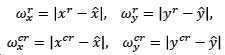
이어, 본 발명은, 센서 트랙들간에 연관성이 존재하는지를 판단할 때, 연관성이 존재하지 않으면 서로 다른 물체로 간주하고 각 센서 트랙에 대해 칼만 필터를 이용하여 개별 추적을 수행할 수 있다.Subsequently, the present invention, when determining whether there is an association between sensor tracks, if the association does not exist, it can be regarded as a different object and perform individual tracking using a Kalman filter for each sensor track.
도 4 및 도 5는 본 발명의 일 실시예에 따른 표적 차량 추적 방법을 설명하기 위한 도면이다.4 and 5 are diagrams for explaining a target vehicle tracking method according to an embodiment of the present invention.
도 4 및 도 5에 도시된 바와 같이, 본 발명은, 자율주행 자동차를 구현하기 위해 다수의 이종 센서가 사용되면서 발생하는 핸드오버 문제를 해결할 수 있다.4 and 5, the present invention can solve the handover problem that occurs when a plurality of heterogeneous sensors are used to implement an autonomous vehicle.
동일한 물체가 다수의 센서 인지 영역에 동시에 존재하는 경우에, 이종의 여러 센서로부터 다수의 센서 트랙이 생성될 수 있는데, 생성된 다수의 센서 트랙이 동일한 물체로부터 기인한 것인지를 올바르게 결정할 수 있어야 한다.In the case where the same object is simultaneously present in multiple sensor recognition areas, multiple sensor tracks can be generated from different heterogeneous sensors, and it should be possible to correctly determine whether the generated multiple sensor tracks originate from the same object.
그리고, 다수의 센서 트랙이 동일한 물체에서 기인한 것인지를 판단한 후에 이들 정보를 융합하여 실제 추적하고자 하는 차량의 위치 및 속도 정보를 실제 거동과 일치하게 표현할 수 있어야 한다.In addition, after determining whether a plurality of sensor tracks originate from the same object, it is necessary to fuse these information to express the position and speed information of the vehicle to be tracked in accordance with the actual behavior.
본 발명은, 추적하고자 하는 차량이 자차의 옆차선 후방에서 전방으로 이동하며 차량을 감지하는 센서의 종류 및 개수가 달라지는 상황을 고려한다.The present invention considers a situation in which the type of vehicle and the number of sensors for detecting a vehicle are different as the vehicle to be tracked moves from the rear side of the host vehicle to the front.
특히, 자차의 전방에 장착된 롱 레인지 레이더(Long Range Radar)와 좌/우 측방에 장착된 숏 레인지 레이더(Short Range Radar)의 단독 혹은 중복 영역에서 표적 차량의 정보가 일관되게 산출될 수 있다.In particular, the information of the target vehicle may be consistently calculated in a single or overlapped region of the long range radar mounted in front of the host vehicle and the short range radar mounted in the left/right sides.
표적 차량의 일부분만이 전방 레이더의 감지 영역 내에 존재하는 경우에, 전방 레이더 트랙은, 차량의 추적 기준점이 아니라 근접한 반사면에 의해 생성될 수 있다.In cases where only a portion of the target vehicle is within the detection area of the front radar, the front radar track can be generated by the adjacent reflective surface rather than the vehicle's tracking reference point.
후방 및 측면은, 측방 레이더 단독 감지 영역이며, 전측방부터 전방 영역은 전방 및 측방 레이더가 동시에 인지하는 영역일 수 있다.The rear and side surfaces are a single side radar detection area, and the front area from the front side may be areas recognized by the front and side radar simultaneously.
차량에 장착된 센서들의 장착 각도는, 사전에 알 수 있는 정보이므로, 센서들의 인지 영역이 중복되는 위치 역시 사전에 알 수 있다.Since the mounting angle of the sensors mounted on the vehicle is information that can be known in advance, it is also possible to know in advance the locations where the recognition areas of the sensors overlap.
본 발명은, 이러한 정보를 활용하여, 해당 영역에서의 각 센서 트랙들의 연관성을 판별함으로써 핸드오버 문제를 해결하고자 한다.The present invention seeks to solve the handover problem by using this information to determine the association of each sensor track in the area.
특히, 자율주행자동차를 구현하기 위해 적용되고 있는 측방 레이더는 대상의 폭, 길이, 진행방향(heading angle) 정보도 함께 제공하므로, 차량을 점 표적(point target)이 아닌 확장 표적(extended target)으로 인지할 수 있다.In particular, the lateral radar that is applied to implement autonomous vehicles also provides the width, length, and heading angle information of the target, so that the vehicle is an extended target rather than a point target. Can be recognized.
따라서, 핸드오버 문제가 발생 가능한 해당 영역에서 다수의 트랙들이 생성된 경우에, 이들이 확장 표적의 범위 내에 동시에 존재하는지 여부를 판별함으로써, 동일 물체로부터 기인되었다는 가정 하에 센서 트랙 정보를 융합할지 혹은 서로 다른 물체에 의해 생성된 트랙으로 다룰지 결정할 수 있다.Therefore, when multiple tracks are generated in a corresponding area where a handover problem may occur, whether to fuse sensor track information under the assumption that they originate from the same object or by determining whether they are simultaneously present in the range of an extended target or different You can decide if you want to treat it as a track created by an object.
본 발명은, 차량에 장착된 센서의 인지 영역을 고려하여 핸드오버 문제 발생 영역을 설정한다.The present invention sets a handover problem generation area in consideration of a recognition area of a sensor mounted on a vehicle.
그리고, 본 발명은, 대상 차량에 대한 측방 레이더 단독 추적을 수행하는 동안에 대상 차량의 폭 및 길이 정보를 추정하며, 진행방향 정보는 지속적으로 갱신한다.In addition, the present invention estimates the width and length information of the target vehicle while performing the lateral radar tracking alone for the target vehicle, and the direction information is continuously updated.
또한, 본 발명은, 핸드오버 영역에서 생성된 다수의 센서 트랙들간의 연관성을 판별하며, 이때 연관/비연관에 대한 판별은 차량의 폭, 길이, 진행방향 정보를 기반으로 수행된다. 즉, 종방향 위치만을 고려하는 경우에 다음의 수식이 사용된다.In addition, the present invention determines the association between a plurality of sensor tracks generated in the handover area, wherein the determination of association/non-association is performed based on vehicle width, length, and direction information. That is, when only the longitudinal position is considered, the following equation is used.

여기서, xcr은 측방 레이더의 종방향 위치, xr은 전방 레이더의 종방향 위치, σx는 상기 센서 트랙의 종위치 오차 표준 편차이다.Here, x cr is the longitudinal position of the lateral radar, x r is the longitudinal position of the front radar, and σ x is the standard deviation of the longitudinal position error of the sensor track.
측방 및 전방 레이더 트랙의 종방향 위치 xcr 및 xr이 동일한 물체로부터 기인한 것으로 가정한다면 위의 수식을 고려할 수 있다.The above equation can be considered if it is assumed that the longitudinal positions x cr and x r of the lateral and front radar tracks originate from the same object.
여기서 표준편차는, 측방 레이더에서 제공된 대상차량의 길이 및 진행방향 정보에 의해 결정될 수 있다.Here, the standard deviation may be determined by the length of the target vehicle provided by the lateral radar and the traveling direction information.
또한, 본 발명은, 다수의 센서 트랙이 동일한 물체에 의해 생성되었다고 판단된 경우에는 또한 이들 트랙이 추적 기준점으로부터 올바르게 산출되었는지를 판단하여 만족하는 경우, 수식 
본 발명의 일 실시예에 따른 표적 차량 추적 방법을 설명하면 다음과 같다.A method of tracking a target vehicle according to an embodiment of the present invention is as follows.
본 발명은, 다수의 이종 센서로부터 센서 인지 정보를 수신한다.The present invention receives sensor recognition information from multiple heterogeneous sensors.
여기서, 다수의 이종 센서로부터 센서 인지 정보를 수신하는 단계는, 좌측방 레이더, 우측방 레이더 및 전방 레이더를 포함하는 다수의 이종 센서로부터 센서 인지 정보를 수신할 수 있다.Here, in the step of receiving the sensor recognition information from the multiple heterogeneous sensors, the sensor recognition information may be received from the multiple heterogeneous sensors including the left side radar, the right side radar, and the front radar.
그리고, 본 발명은, 수신된 센서 인지 정보를 토대로 센서 트랙을 생성한다.Then, the present invention generates a sensor track based on the received sensor recognition information.
이어, 본 발명은, 생성된 센서 트랙이 다수 개인지 확인한다.Next, the present invention checks whether the generated sensor tracks are many.
다음, 본 발명은, 센서 트랙들간에 연관성이 존재하는지를 판단한다.Next, the present invention determines whether an association exists between the sensor tracks.
여기서, 센서 트랙들간에 연관성이 존재하는지를 판단하는 단계는, 센서 트랙들간에 연관성이 존재하는지를 판단하기 이전에, 상기 다수의 센서 트랙들에 대한 추적 기준점을 동일한 값으로 일치시키는 단계를 더 포함할 수 있다.Here, determining whether there is an association between the sensor tracks, before determining whether there is an association between the sensor tracks, may further include matching the tracking reference points for the plurality of sensor tracks to the same value. have.
이때, 추적 기준점은, x = xcr + l/2·sin(θ), y = ycr + l/2·cos(θ) (여기서, x는 추적 기준점의 종방향 위치, y는 추적 기준점의 횡방향 위치, xcr은 측방 레이더의 종방향 위치, ycr은 측방 레이더의 횡방향 위치, l은 표적 차량의 길이임)으로 표현되는 수식에 의해 산출될 수 있다.At this time, the tracking reference point is x = x cr + l/2·sin(θ), y = y cr + l/2·cos(θ) (where x is the longitudinal position of the tracking reference point, y is the tracking reference point The lateral position, x cr is the longitudinal position of the lateral radar, y cr is the lateral position of the lateral radar, and l is the length of the target vehicle.
또한, 센서 트랙들간에 연관성이 존재하는지를 판단하는 단계는, 센서 트랙들간에 연관성이 존재하는지를 판단하기 이전에, 센서 트랙이 단일 센서의 단독 감지 영역에 위치하면 칼만 필터를 이용하여 표적 차량의 단독 추적을 수행하는 단계를 더 포함할 수 있다.In addition, the step of determining whether there is an association between the sensor tracks, prior to determining whether an association exists between the sensor tracks, if the sensor track is located in the single detection area of a single sensor, the Kalman filter is used to track the target vehicle alone. It may further include the step of performing.
또한, 센서 트랙들간에 연관성이 존재하는지를 판단하는 단계는, 연관성이 존재하지 않으면 서로 다른 물체로 간주하고 각 센서 트랙에 대해 칼만 필터를 이용하여 개별 추적을 수행할 수 있다.In addition, the step of determining whether there is an association between sensor tracks may be regarded as different objects if there is no association, and individual tracking may be performed using a Kalman filter for each sensor track.
그리고, 본 발명은, 연관성이 존재하면 상기 센서 트랙들의 추적 기준점이 동일한지를 판단한다.In addition, the present invention determines whether the tracking reference points of the sensor tracks are the same when the association exists.
여기서, 센서 트랙들간에 연관성이 존재하는지를 판단하는 단계는, {xr: (xcr - xr)2 ≤ σx 2} {yr: (ycr - yr)2 ≤ σy 2} (여기서, xr은 전방 레이더의 종방향 위치, yr은 전방 레이더의 횡방향 위치, xcr은 측방 레이더의 종방향 위치, ycr은 측방 레이더의 횡방향 위치, σx는 상기 센서 트랙의 종위치 오차 표준 편차, σy는 상기 센서 트랙의 횡위치 오차 표준 편차임)으로 표현되는 조건과, σx 

또한, 센서 트랙들간에 연관성이 존재하는지를 판단하는 단계는, 센서 트랙들이 상호간에 정규 분포를 만족하도록, 
여기서, 센서 트랙들의 추적 기준점이 동일한지를 판단하는 단계는, (xcr ± w/2, ycr + ㅣ) ∈ 

이때, 제1 조건은, 표적 차량의 전체 또는 일부분이 전방 레이더의 감지 영역에 포함되는지를판별하는 조건이고, 제2 조건은, 전방 레이더 트랙과 측방 레이더 트랙이 동일한 추적 기준점에 의해 생성되었는지를 판별하는 조건일 수 있다.At this time, the first condition is a condition for determining whether all or part of the target vehicle is included in the detection area of the front radar, and the second condition determines whether the front radar track and the lateral radar track are generated by the same tracking reference point. It may be a condition.
이어, 본 발명은, 추적 기준점이 동일하면 상기 센서 트랙들을 융합하여 센서퓨전 트랙을 출력한다.Next, in the present invention, if the tracking reference points are the same, the sensor tracks are fused to output a sensor fusion track.
여기서, 센서 트랙들을 융합하여 센서퓨전 트랙을 출력하는 단계는, 
또한, 센서 트랙들을 융합하여 센서퓨전 트랙을 출력하는 단계는, 센서 트랙의 종위치에 대해서 전방 레이더 트랙을 신뢰하도록 상기 전방 레이더 트랙 정보에 대한 융합 가중치가 설정되고, 센서 트랙의 횡위치에 대해서 측방 레이더 트랙을 신뢰하도록 상기 측방 레이더 트랙 정보에 대한 융합 가중치가 설정될 수 있다.In addition, in the step of fusing the sensor tracks and outputting the sensor fusion track, the fusion weight for the front radar track information is set to trust the front radar track with respect to the longitudinal position of the sensor track, and lateral to the lateral position of the sensor track. A fusion weight for the lateral radar track information can be set to trust the radar track.
또한, 센서 트랙들을 융합하여 센서퓨전 트랙을 출력하는 단계는, 전방 및 측방 레이더 트랙 정보에 대한 융합 가중치를, 
그리고, 본 발명은, 출력된 센서퓨전 트랙을 추적한다.Then, the present invention tracks the output of the sensor fusion track.
다음, 본 발명은, 추적한 센서퓨전 트랙을 관리한다.Next, the present invention manages the tracked sensor fusion track.
또한, 본 발명의 일 실시예에 따른 표적 차량 추적 장치의 표적 차량 추적 방법을 실행시키기 위한 프로그램을 기록한 컴퓨터로 읽을 수 있는 기록매체로서, 본 발명의 실시예에 따른 표적 차량 추적 방법에서 제공된 과정을 수행할 수 있다.In addition, as a computer-readable recording medium recording a program for executing a target vehicle tracking method of a target vehicle tracking device according to an embodiment of the present invention, the process provided in the target vehicle tracking method according to an embodiment of the present invention Can be done.
한편, 본 발명의 일 실시예에 따른 차량은, 주변 차량을 감지하는 센싱 장치와, 센싱 장치로부터 수신되는 다수의 센서 인식 정보를 토대로 센서퓨전 트랙을 출력하는 표적 차량 추적 장치를 포함하고, 표적 차량 추적 장치는, 다수의 이종 센서로부터 센서 인지 정보를 수신하여 센서 트랙을 생성하는 센서 트랙 처리부와, 생성된 센서 트랙이 다수 개이면 센서 트랙들간에 연관성이 존재하는지를 판단하고 연관성이 존재하면 센서 트랙들의 추적 기준점이 동일한지를 판단하며 추적 기준점이 동일하면 센서 트랙들을 융합하여 센서퓨전 트랙을 출력하는 센서 트랙 연관성 판단부와, 출력된 센서퓨전 트랙을 추적하는 센서퓨전 트랙 추적부와, 추적한 센서퓨전 트랙을 관리하는 센서퓨전 트랙 관리부를 포함할 수 있다.On the other hand, the vehicle according to an embodiment of the present invention, a sensing device for sensing a surrounding vehicle, and a target vehicle tracking device for outputting a sensor fusion track based on a plurality of sensor recognition information received from the sensing device, the target vehicle The tracking device receives sensor recognition information from a plurality of heterogeneous sensors and generates a sensor track, and if there are multiple sensor tracks, determines whether there is an association between the sensor tracks, and if there is an association, the sensor tracks Determine whether the tracking reference point is the same, and if the tracking reference point is the same, the sensor track association determination unit that fuses the sensor tracks to output the sensor fusion track, the sensor fusion track tracking unit that tracks the output sensor fusion track, and the tracked sensor fusion track It may include a sensor fusion track management unit for managing the.
이와 같이, 본 발명은, 다수의 센서 트랙들간에 연관성이 존재하는지를 판단하고 센서 트랙들의 추적 기준점이 동일한지를 판단하여 이를 토대로 센서퓨전 트랙을 생성함으로써, 다수의 센서 트랙들이 동일한 물체로부터 기인하는지를 정확하게 판별하여 표적 차량을 정밀하게 추적할 수 있다.As described above, the present invention accurately determines whether multiple sensor tracks originate from the same object by determining whether there is an association between the multiple sensor tracks and determining whether the tracking reference points of the sensor tracks are the same, thereby generating a sensor fusion track. This enables precise tracking of the target vehicle.
또한, 본 발명은, 자율주행 자동차를 구현하기 위해 다수의 이종 센서가 사용되면서 발생하는 핸드오버 문제를 해결할 수 있다.In addition, the present invention can solve the handover problem that occurs when a plurality of heterogeneous sensors are used to implement an autonomous vehicle.
또한, 본 발명은, 자차량의 옆차선에서 종방향 직진 주행하는 차량의 위치 정보가 실제 차량 거동과 부합하게 산출되도록 할 수 있다.In addition, according to the present invention, the position information of the vehicle traveling straight in the longitudinal direction in the side lane of the host vehicle can be calculated in accordance with the actual vehicle behavior.
또한, 본 발명은, 단순히 다수의 센서 트랙이 동일한 물체에 해당됨을 판별하는 것에서 더 나아가 각 센서 트랙의 위치 정보들을 적절하게 융합하는 방안을 제안하여 자율주행 자동차 구현을 위해 필요한 정밀 제어를 가능하게 할 수 있다.In addition, the present invention further proposes a method of appropriately fusion of location information of each sensor track by simply determining that a plurality of sensor tracks correspond to the same object, thereby enabling precise control required for autonomous vehicle implementation. Can.
따라서, 본 발명은, 이종 다중센서를 이용한 표적 차량 추적 기법에 사용될 수 있다.Therefore, the present invention can be used in a target vehicle tracking technique using heterogeneous multiple sensors.
전술한 본 발명은, 프로그램이 기록된 매체에 컴퓨터가 읽을 수 있는 코드로서 구현하는 것이 가능하다. 컴퓨터가 읽을 수 있는 매체는, 컴퓨터 시스템에 의하여 읽혀질 수 있는 데이터가 저장되는 모든 종류의 기록장치를 포함한다. 컴퓨터가 읽을 수 있는 매체의 예로는, HDD(Hard Disk Drive), SSD(Solid State Disk), SDD(Silicon Disk Drive), ROM, RAM, CD-ROM, 자기 테이프, 플로피 디스크, 광 데이터 저장 장치 등이 있으며, 또한 캐리어 웨이브(예를 들어, 인터넷을 통한 전송)의 형태로 구현되는 것도 포함한다.The above-described present invention can be embodied as computer readable codes on a medium on which a program is recorded. The computer-readable medium includes all types of recording devices in which data that can be read by a computer system are stored. Examples of computer-readable media include a hard disk drive (HDD), solid state disk (SSD), silicon disk drive (SDD), ROM, RAM, CD-ROM, magnetic tape, floppy disk, and optical data storage device. This includes, and is also implemented in the form of a carrier wave (eg, transmission over the Internet).
따라서, 상기의 상세한 설명은 모든 면에서 제한적으로 해석되어서는 아니되고 예시적인 것으로 고려되어야 한다. 본 발명의 범위는 첨부된 청구항의 합리적 해석에 의해 결정되어야 하고, 본 발명의 등가적 범위 내에서의 모든 변경은 본 발명의 범위에 포함된다.Accordingly, the above detailed description should not be construed as limiting in all respects, but should be considered illustrative. The scope of the invention should be determined by rational interpretation of the appended claims, and all changes within the equivalent scope of the invention are included in the scope of the invention.
110: 센서 트랙 처리부
120: 센서 트랙 연관성 판단부
130: 센서퓨전 트랙 추적부
140: 센서퓨전 트랙 관리부110: sensor track processing unit
120: sensor track association determination unit
130: sensor fusion track tracker
140: sensor fusion track management
Claims (34)
상기 생성된 센서 트랙이 다수 개이면 상기 센서 트랙들간에 연관성이 존재하는지를 판단하고, 상기 연관성이 존재하면 상기 센서 트랙들의 추적 기준점이 동일한지를 판단하며, 상기 추적 기준점이 동일하면 상기 센서 트랙들을 융합하여 센서퓨전 트랙을 출력하는 센서 트랙 연관성 판단부;
상기 출력된 센서퓨전 트랙을 추적하는 센서퓨전 트랙 추적부; 그리고,
상기 추적한 센서퓨전 트랙을 관리하는 센서퓨전 트랙 관리부를 포함하는 것을 특징으로 하는 표적 차량 추적 장치.A sensor track processing unit receiving sensor recognition information from a plurality of heterogeneous sensors and generating a sensor track;
If there are a plurality of sensor tracks, it is determined whether an association exists between the sensor tracks, and if the association exists, it is determined whether the tracking reference points of the sensor tracks are the same. A sensor track association determination unit outputting a sensor fusion track;
A sensor fusion track tracking unit tracking the output sensor fusion track; And,
And a sensor fusion track management unit that manages the tracked sensor fusion track.
좌측방 레이더, 우측방 레이더 및 전방 레이더를 포함하는 다수의 이종 센서로부터 센서 인지 정보를 수신하는 것을 특징으로 하는 표적 차량 추적 장치.According to claim 1, The sensor track processing unit,
Target vehicle tracking device, characterized in that for receiving the sensor recognition information from a plurality of heterogeneous sensors, including a left-side radar, right-side radar and front radar.
상기 센서 트랙들간에 연관성이 존재하는지를 판단하기 이전에, 상기 다수의 센서 트랙들에 대한 추적 기준점을 동일한 값으로 일치시키는 것을 특징으로 하는 표적 차량 추적 장치.According to claim 1, The sensor track association determination unit,
A target vehicle tracking device, characterized in that the tracking reference points for the plurality of sensor tracks are matched to the same value before determining whether an association exists between the sensor tracks.
표적 차량의 후방 범퍼 중앙값으로 설정하는 것을 특징으로 하는 표적 차량 추적 장치.The method of claim 3, wherein the tracking reference point,
Target vehicle tracking device, characterized in that set to the median rear bumper of the target vehicle.
x = xcr + l/2·sin(θ), y = ycr + l/2·cos(θ) (여기서, x는 추적 기준점의 종방향 위치, y는 추적 기준점의 횡방향 위치, xcr은 측방 레이더의 종방향 위치, ycr은 측방 레이더의 횡방향 위치, l은 표적 차량의 길이임)으로 표현되는 수식에 의해 산출되는 것을 특징으로 하는 표적 차량 추적 장치.The method of claim 3, wherein the tracking reference point,
x = x cr + l/2·sin(θ), y = y cr + l/2·cos(θ) (where x is the longitudinal position of the tracking reference point, y is the transverse position of the tracking reference point, x cr Is a longitudinal position of the lateral radar, y cr is the lateral position of the lateral radar, l is the target vehicle tracking device, characterized in that calculated by the formula expressed by the expression.
상기 센서 트랙들간에 연관성이 존재하는지를 판단하기 이전에, 상기 센서 트랙이 단일 센서의 단독 감지 영역에 위치하면 칼만 필터를 이용하여 표적 차량의 단독 추적을 수행하는 것을 특징으로 하는 표적 차량 추적 장치.According to claim 1, The sensor track association determination unit,
The target vehicle tracking device, characterized in that, prior to determining whether an association exists between the sensor tracks, when the sensor track is located in a single sensor detection area, a Kalman filter is used to track the target vehicle alone.
상기 표적 차량의 단독 추적을 수행할 때, 상기 표적 차량의 폭 및 길이 정보를 추정하는 것을 특징으로 하는 표적 차량 추적 장치.According to claim 6, The sensor track association determination unit,
A target vehicle tracking device for estimating width and length information of the target vehicle when performing single tracking of the target vehicle.
상기 표적 차량의 폭 및 길이 정보를 추정할 때, 상기 센서 트랙의 클래스(class) 정보와 그에 상응하는 폭 및 길이 정보의 일치성을 확인하는 것을 특징으로 하는 표적 차량 추적 장치.The sensor track association determination unit of claim 7,
When estimating the width and length information of the target vehicle, the target vehicle tracking device, characterized in that for confirming the correspondence of the class (class) information of the sensor track and the corresponding width and length information.
상기 센서 트랙들간에 연관성이 존재하는지를 판단할 때, {xr: (xcr - xr)2 ≤ σx 2} {yr: (ycr - yr)2 ≤ σy 2} (여기서, xr은 전방 레이더의 종방향 위치, yr은 전방 레이더의 횡방향 위치, xcr은 측방 레이더의 종방향 위치, ycr은 측방 레이더의 횡방향 위치, σx는 상기 센서 트랙의 종위치 오차 표준 편차, σy는 상기 센서 트랙의 횡위치 오차 표준 편차임)으로 표현되는 조건과 σx


When determining whether there is an association between the sensor tracks, {x r : (x cr -x r ) 2 ≤ σ x 2 } {y r : (y cr -y r ) 2 ≤ σ y 2 } (where, x r is the longitudinal position of the front radar, y r is the lateral position of the front radar, x cr is the longitudinal position of the lateral radar, y cr is the lateral position of the lateral radar, σ x is the longitudinal position error of the sensor track Standard deviation, σ y is the standard deviation of the lateral position error of the sensor track) and σ x
상기 센서 트랙들간에 연관성이 존재하는지를 판단할 때, 상기 센서 트랙들이 상호간에 정규 분포를 만족하도록,

When determining whether there is an association between the sensor tracks, the sensor tracks satisfy a normal distribution with each other,
상기 센서 트랙들의 추적 기준점이 동일한지를 판단할 때, (xcr ± w/2, ycr + ㅣ) ∈


When determining whether the tracking points of the sensor tracks are the same, (x cr ± w/2, y cr + ㅣ) ∈
상기 표적 차량의 전체 또는 일부분이 전방 레이더의 감지 영역에 포함되는지를 판별하는 조건이고,
상기 제2 조건은,
전방 레이더 트랙과 측방 레이더 트랙이 동일한 추적 기준점에 의해 생성되었는지를 판별하는 조건인 것을 특징으로 하는 표적 차량 추적 장치.The method of claim 10, wherein the first condition,
It is a condition for determining whether all or part of the target vehicle is included in the detection area of the front radar,
The second condition is,
A target vehicle tracking device, characterized in that it is a condition for determining whether the front radar track and the side radar track are generated by the same tracking reference point.
상기 센서 트랙들을 융합하여 센서퓨전 트랙을 출력할 때,

When fusion of the sensor tracks to output a sensor fusion track,
상기 센서 트랙들을 융합하여 센서퓨전 트랙을 출력할 때, 센서 트랙의 종위치에 대해서 전방 레이더 트랙을 신뢰하도록 상기 전방 레이더 트랙 정보에 대한 융합 가중치가 설정되고, 센서 트랙의 횡위치에 대해서 측방 레이더 트랙을 신뢰하도록 상기 측방 레이더 트랙 정보에 대한 융합 가중치가 설정되는 것을 특징으로 하는 표적 차량 추적 장치.The sensor track association determining unit of claim 13,
When the sensor tracks are fused to output the sensor fusion track, the fusion weight for the front radar track information is set to trust the front radar track for the longitudinal position of the sensor track, and the lateral radar track is relative to the lateral position of the sensor track. Target vehicle tracking device, characterized in that the fusion weight for the lateral radar track information is set to trust.
상기 센서 트랙들을 융합하여 센서퓨전 트랙을 출력할 때, 전방 및 측방 레이더 트랙 정보에 대한 융합 가중치를,

When the sensor tracks are fused and the sensor fusion track is output, the fusion weights for the front and side radar track information,
상기 센서 트랙들간에 연관성이 존재하는지를 판단할 때, 상기 연관성이 존재하지 않으면 서로 다른 물체로 간주하고 각 센서 트랙에 대해 칼만 필터를 이용하여 개별 추적을 수행하는 것을 특징으로 하는 표적 차량 추적 장치.According to claim 1, The sensor track association determination unit,
When determining whether there is an association between the sensor tracks, the target vehicle tracking device is characterized in that if the association does not exist, each object is regarded as a different object and individual tracking is performed using a Kalman filter for each sensor track.
상기 수신된 센서 인지 정보를 토대로 센서 트랙을 생성하는 단계;
상기 생성된 센서 트랙이 다수 개인지 확인하는 단계;
상기 센서 트랙들간에 연관성이 존재하는지를 판단하는 단계;
상기 연관성이 존재하면 상기 센서 트랙들의 추적 기준점이 동일한지를 판단하는 단계;
상기 추적 기준점이 동일하면 상기 센서 트랙들을 융합하여 센서퓨전 트랙을 출력하는 단계;
상기 출력된 센서퓨전 트랙을 추적하는 단계; 그리고,
상기 추적한 센서퓨전 트랙을 관리하는 단계를 포함하는 것을 특징으로 하는 표적 차량 추적 방법.Receiving sensor recognition information from a plurality of heterogeneous sensors;
Generating a sensor track based on the received sensor recognition information;
Checking whether the generated sensor tracks are multiple;
Determining whether an association exists between the sensor tracks;
Determining whether the tracking reference points of the sensor tracks are the same if the association exists;
Fusing the sensor tracks to output a sensor fusion track when the tracking reference points are the same;
Tracking the output sensor fusion track; And,
And managing the tracked sensor fusion track.
좌측방 레이더, 우측방 레이더 및 전방 레이더를 포함하는 다수의 이종 센서로부터 센서 인지 정보를 수신하는 것을 특징으로 하는 표적 차량 추적 방법.18. The method of claim 17, Receiving sensor recognition information from the plurality of heterogeneous sensors,
A target vehicle tracking method comprising receiving sensor recognition information from a plurality of heterogeneous sensors including a left-side radar, a right-side radar, and a front-facing radar.
상기 센서 트랙들간에 연관성이 존재하는지를 판단하기 이전에, 상기 다수의 센서 트랙들에 대한 추적 기준점을 동일한 값으로 일치시키는 단계를 더 포함하는 것을 특징으로 하는 표적 차량 추적 방법.The method of claim 17, wherein determining whether there is an association between the sensor tracks,
And prior to determining whether there is an association between the sensor tracks, matching the tracking reference points for the plurality of sensor tracks with the same value.
표적 차량의 후방 범퍼 중앙값으로 설정하는 것을 특징으로 하는 표적 차량 추적 방법.The method of claim 19, wherein the tracking reference point,
Target vehicle tracking method, characterized in that set to the median rear bumper of the target vehicle.
x = xcr + l/2·sin(θ), y = ycr + l/2·cos(θ) (여기서, x는 추적 기준점의 종방향 위치, y는 추적 기준점의 횡방향 위치, xcr은 측방 레이더의 종방향 위치, ycr은 측방 레이더의 횡방향 위치, l은 표적 차량의 길이임)으로 표현되는 수식에 의해 산출되는 것을 특징으로 하는 표적 차량 추적 방법.The method of claim 19, wherein the tracking reference point,
x = x cr + l/2·sin(θ), y = y cr + l/2·cos(θ) (where x is the longitudinal position of the tracking reference point, y is the transverse position of the tracking reference point, x cr Is the longitudinal position of the lateral radar, y cr is the lateral position of the lateral radar, l is the target vehicle tracking method, characterized in that calculated by the expression expressed by the formula.
상기 센서 트랙들간에 연관성이 존재하는지를 판단하기 이전에, 상기 센서 트랙이 단일 센서의 단독 감지 영역에 위치하면 칼만 필터를 이용하여 표적 차량의 단독 추적을 수행하는 단계를 더 포함하는 것을 특징으로 하는 표적 차량 추적 방법.The method of claim 17, wherein determining whether there is an association between the sensor tracks,
The target characterized in that it further comprises the step of performing a sole tracking of the target vehicle using a Kalman filter if the sensor track is located in a single sensing area of a single sensor before determining whether there is an association between the sensor tracks. Vehicle tracking method.
상기 표적 차량의 폭 및 길이 정보를 추정하는 것을 특징으로 하는 표적 차량 추적 방법.The method of claim 22, wherein performing the sole tracking of the target vehicle,
Target vehicle tracking method, characterized in that for estimating the width and length information of the target vehicle.
상기 센서 트랙의 클래스(class) 정보와 그에 상응하는 폭 및 길이 정보의 일치성을 확인하는 것을 특징으로 하는 표적 차량 추적 방법.The method of claim 23, wherein estimating the width and length information of the target vehicle,
A method for tracking a target vehicle, characterized in that the class information of the sensor track and the corresponding width and length information are checked.
{xr: (xcr - xr)2 ≤ σx 2}
{yr: (ycr - yr)2 ≤ σy 2} (여기서, xr은 전방 레이더의 종방향 위치, yr은 전방 레이더의 횡방향 위치, xcr은 측방 레이더의 종방향 위치, ycr은 측방 레이더의 횡방향 위치, σx는 상기 센서 트랙의 종위치 오차 표준 편차, σy는 상기 센서 트랙의 횡위치 오차 표준 편차임)으로 표현되는 조건과,
σx


{x r : (x cr -x r ) 2 ≤ σ x 2 }
{y r : (y cr -y r ) 2 ≤ σ y 2 } (where x r is the longitudinal position of the front radar, y r is the transverse position of the front radar, x cr is the longitudinal position of the lateral radar, y cr is the lateral position of the lateral radar, σ x is the standard deviation of the longitudinal position error of the sensor track, σ y is the standard deviation of the lateral position error of the sensor track),
σ x
상기 센서 트랙들이 상호간에 정규 분포를 만족하도록,

In order for the sensor tracks to satisfy a normal distribution with each other,
(xcr ± w/2, ycr + ㅣ) ∈


{xr: (xcr - xr)2 ≤ (σx/2)2} {yr: (ycr - yr)2 ≤ (σy/5)2} (여기서, xr은 전방 레이더의 종방향 위치, yr은 전방 레이더의 횡방향 위치, xcr은 측방 레이더의 종방향 위치, ycr은 측방 레이더의 횡방향 위치, σx는 상기 센서 트랙의 종위치 오차 표준 편차, σy는 상기 센서 트랙의 횡위치 오차 표준 편차임)으로 표현되는 제2 조건에 의해 판단되는 것을 특징으로 하는 표적 차량 추적 방법.18. The method of claim 17, wherein determining whether the tracking reference points of the sensor tracks are the same,
(x cr ± w/2, y cr + ㅣ) ∈
{x r : (x cr -x r ) 2 ≤ (σ x /2) 2 } {y r : (y cr -y r ) 2 ≤ (σ y /5) 2 } (where x r is the forward radar The longitudinal position of, y r is the lateral position of the front radar, x cr is the longitudinal position of the lateral radar, y cr is the lateral position of the lateral radar, σ x is the standard deviation of the longitudinal position error of the sensor track, σ y Is determined by the second condition represented by the standard deviation of the lateral position error of the sensor track.
상기 표적 차량의 전체 또는 일부분이 전방 레이더의 감지 영역에 포함되는지를 판별하는 조건이고.
상기 제2 조건은,
전방 레이더 트랙과 측방 레이더 트랙이 동일한 추적 기준점에 의해 생성되었는지를 판별하는 조건인 것을 특징으로 하는 표적 차량 추적 방법.The method of claim 27, wherein the first condition,
It is a condition for determining whether all or part of the target vehicle is included in the detection area of the front radar.
The second condition is,
A target vehicle tracking method characterized in that it is a condition for determining whether the front radar track and the side radar track are generated by the same tracking reference point.

센서 트랙의 종위치에 대해서 전방 레이더 트랙을 신뢰하도록 상기 전방 레이더 트랙 정보에 대한 융합 가중치가 설정되고, 센서 트랙의 횡위치에 대해서 측방 레이더 트랙을 신뢰하도록 상기 측방 레이더 트랙 정보에 대한 융합 가중치가 설정되는 것을 특징으로 하는 표적 차량 추적 방법.30. The method of claim 29, The step of fusing the sensor tracks to output the sensor fusion track,
The fusion weight for the front radar track information is set to trust the forward radar track for the longitudinal position of the sensor track, and the fusion weight for the lateral radar track information is set to trust the lateral radar track for the lateral position of the sensor track. Target vehicle tracking method, characterized in that.
전방 및 측방 레이더 트랙 정보에 대한 융합 가중치를,

The fusion weights for the forward and lateral radar track information,
상기 연관성이 존재하지 않으면 서로 다른 물체로 간주하고 각 센서 트랙에 대해 칼만 필터를 이용하여 개별 추적을 수행하는 것을 특징으로 하는 표적 차량 추적 방법.The method of claim 17, wherein determining whether there is an association between the sensor tracks,
If the association does not exist, the target vehicle tracking method is characterized in that individual tracking is performed using a Kalman filter for each sensor track.
상기 센싱 장치로부터 수신되는 다수의 센서 인식 정보를 토대로 센서퓨전 트랙을 출력하는 표적 차량 추적 장치를 포함하고,
상기 표적 차량 추적 장치는,
다수의 이종 센서로부터 센서 인지 정보를 수신하여 센서 트랙을 생성하는 센서 트랙 처리부;
상기 생성된 센서 트랙이 다수 개이면 상기 센서 트랙들간에 연관성이 존재하는지를 판단하고, 상기 연관성이 존재하면 상기 센서 트랙들의 추적 기준점이 동일한지를 판단하며, 상기 추적 기준점이 동일하면 상기 센서 트랙들을 융합하여 센서퓨전 트랙을 출력하는 센서 트랙 연관성 판단부;
상기 출력된 센서퓨전 트랙을 추적하는 센서퓨전 트랙 추적부; 그리고,
상기 추적한 센서퓨전 트랙을 관리하는 센서퓨전 트랙 관리부를 포함하는 것을 특징으로 하는 차량.A sensing device that senses a surrounding vehicle; And,
And a target vehicle tracking device that outputs a sensor fusion track based on a plurality of sensor recognition information received from the sensing device,
The target vehicle tracking device,
A sensor track processing unit receiving sensor recognition information from a plurality of heterogeneous sensors and generating a sensor track;
If there are a plurality of sensor tracks, it is determined whether an association exists between the sensor tracks, and if the association exists, it is determined whether the tracking reference points of the sensor tracks are the same. A sensor track association determination unit outputting a sensor fusion track;
A sensor fusion track tracking unit tracking the output sensor fusion track; And,
And a sensor fusion track management unit managing the tracked sensor fusion track.
Priority Applications (2)
| Application Number | Priority Date | Filing Date | Title |
|---|---|---|---|
| KR1020180164522A KR102569904B1 (en) | 2018-12-18 | 2018-12-18 | Apparatus and method for tracking target vehicle and vehicle including the same |
| US16/535,974 US11340344B2 (en) | 2018-12-18 | 2019-08-08 | Apparatus and method for tracking target vehicle and vehicle including the same |
Applications Claiming Priority (1)
| Application Number | Priority Date | Filing Date | Title |
|---|---|---|---|
| KR1020180164522A KR102569904B1 (en) | 2018-12-18 | 2018-12-18 | Apparatus and method for tracking target vehicle and vehicle including the same |
Publications (2)
| Publication Number | Publication Date |
|---|---|
| KR20200081525A true KR20200081525A (en) | 2020-07-08 |
| KR102569904B1 KR102569904B1 (en) | 2023-08-24 |
Family
ID=71073511
Family Applications (1)
| Application Number | Title | Priority Date | Filing Date |
|---|---|---|---|
| KR1020180164522A Active KR102569904B1 (en) | 2018-12-18 | 2018-12-18 | Apparatus and method for tracking target vehicle and vehicle including the same |
Country Status (2)
| Country | Link |
|---|---|
| US (1) | US11340344B2 (en) |
| KR (1) | KR102569904B1 (en) |
Families Citing this family (17)
| Publication number | Priority date | Publication date | Assignee | Title |
|---|---|---|---|---|
| US11435439B2 (en) * | 2019-08-19 | 2022-09-06 | Waymo Llc | Multibounce target mitigation |
| CN110646825B (en) * | 2019-10-22 | 2022-01-25 | 北京国家新能源汽车技术创新中心有限公司 | Positioning method, positioning system and automobile |
| JP7397759B2 (en) * | 2020-05-29 | 2023-12-13 | 日立Astemo株式会社 | electronic control unit |
| CN111857152B (en) * | 2020-07-31 | 2024-07-19 | 北京京东乾石科技有限公司 | Method and device for generating vehicle control information |
| DE102020215504A1 (en) * | 2020-12-09 | 2022-06-09 | Robert Bosch Gesellschaft mit beschränkter Haftung | Method and device for detecting objects in the surroundings of a vehicle |
| CN113093134B (en) * | 2021-02-23 | 2024-09-06 | 福瑞泰克智能系统有限公司 | Extended target tracking method and device, sensing equipment and vehicle |
| CN114375406B (en) * | 2021-04-12 | 2025-05-06 | 武汉智行者科技有限公司 | Target speed estimation method, device and storage medium |
| CN115201804B (en) * | 2021-04-12 | 2025-08-08 | 武汉智行者科技有限公司 | Target speed estimation method, device and storage medium |
| US12298434B2 (en) * | 2021-04-29 | 2025-05-13 | Qualcomm Incorporated | Intra-vehicle radar handover |
| US20230003871A1 (en) * | 2021-06-30 | 2023-01-05 | Zoox, Inc. | Associating radar data with tracked objects |
| US20230003872A1 (en) * | 2021-06-30 | 2023-01-05 | Zoox, Inc. | Tracking objects with radar data |
| KR20230012780A (en) * | 2021-07-16 | 2023-01-26 | 현대자동차주식회사 | Method and apparatus for fusing sensor information, and recording medium for recording program performing the method |
| CN114861785A (en) * | 2022-04-26 | 2022-08-05 | 云控智行科技有限公司 | Fusion method and device of roadside multi-sensors |
| CN115034324B (en) * | 2022-06-21 | 2023-05-02 | 同济大学 | Multi-sensor fusion perception efficiency enhancement method |
| CN115169493B (en) * | 2022-07-28 | 2025-10-03 | 苏州轻棹科技有限公司 | A target trajectory processing method based on multi-sensor fusion |
| KR20240036872A (en) * | 2022-09-14 | 2024-03-21 | 현대자동차주식회사 | Method and sysyem for estimating reliability of bounding point of track |
| CN115840221B (en) | 2023-02-20 | 2023-04-25 | 上海几何伙伴智能驾驶有限公司 | A Method of Target Feature Extraction and Multi-Target Tracking Based on 4D Millimeter Wave Radar |
Citations (4)
| Publication number | Priority date | Publication date | Assignee | Title |
|---|---|---|---|---|
| JP2005257510A (en) * | 2004-03-12 | 2005-09-22 | Alpine Electronics Inc | Another car detection device and method |
| JP2015224928A (en) * | 2014-05-27 | 2015-12-14 | 株式会社デンソー | Target detector |
| JP2017061167A (en) * | 2015-09-23 | 2017-03-30 | トヨタ自動車株式会社 | Vehicle travel control device |
| JP6194520B1 (en) * | 2016-06-24 | 2017-09-13 | 三菱電機株式会社 | Object recognition device, object recognition method, and automatic driving system |
Family Cites Families (17)
| Publication number | Priority date | Publication date | Assignee | Title |
|---|---|---|---|---|
| US5138321A (en) * | 1991-10-15 | 1992-08-11 | International Business Machines Corporation | Method for distributed data association and multi-target tracking |
| US5317319A (en) * | 1992-07-17 | 1994-05-31 | Hughes Aircraft Company | Automatic global radar/IR/ESM track association based on ranked candidate pairings and measures of their proximity |
| US5414643A (en) * | 1993-06-14 | 1995-05-09 | Hughes Aircraft Company | Method and apparatus for continuous time representation of multiple hypothesis tracking data |
| GB0115433D0 (en) * | 2001-06-23 | 2001-08-15 | Lucas Industries Ltd | An object location system for a road vehicle |
| US6604028B2 (en) * | 2001-09-26 | 2003-08-05 | Raytheon Company | Vertical motion detector for air traffic control |
| US6862537B2 (en) * | 2002-03-21 | 2005-03-01 | Ford Global Technologies Llc | Sensor fusion system architecture |
| US8812226B2 (en) * | 2009-01-26 | 2014-08-19 | GM Global Technology Operations LLC | Multiobject fusion module for collision preparation system |
| US8482486B2 (en) * | 2009-04-02 | 2013-07-09 | GM Global Technology Operations LLC | Rear view mirror on full-windshield head-up display |
| US8704887B2 (en) * | 2010-12-02 | 2014-04-22 | GM Global Technology Operations LLC | Multi-object appearance-enhanced fusion of camera and range sensor data |
| US9594160B2 (en) * | 2014-02-25 | 2017-03-14 | The Mitre Corporation | Track associator |
| US20170242117A1 (en) * | 2016-02-19 | 2017-08-24 | Delphi Technologies, Inc. | Vision algorithm performance using low level sensor fusion |
| FR3054672B1 (en) * | 2016-07-29 | 2019-09-13 | Valeo Schalter Und Sensoren Gmbh | METHOD AND SYSTEM FOR ASSOCIATING MOBILE OBJECT DETECTION AND TRACKING DATA FOR MOTOR VEHICLE |
| US11067996B2 (en) * | 2016-09-08 | 2021-07-20 | Siemens Industry Software Inc. | Event-driven region of interest management |
| US10466361B2 (en) * | 2017-03-14 | 2019-11-05 | Toyota Research Institute, Inc. | Systems and methods for multi-sensor fusion using permutation matrix track association |
| US10602242B2 (en) * | 2017-06-14 | 2020-03-24 | GM Global Technology Operations LLC | Apparatus, method and system for multi-mode fusion processing of data of multiple different formats sensed from heterogeneous devices |
| US10551838B2 (en) * | 2017-08-08 | 2020-02-04 | Nio Usa, Inc. | Method and system for multiple sensor correlation diagnostic and sensor fusion/DNN monitor for autonomous driving application |
| US10866307B2 (en) * | 2017-12-29 | 2020-12-15 | Automotive Research & Testing Center | Method for analyzing error and existence probability of multi-sensor fusion of obstacle detection |
-
2018
- 2018-12-18 KR KR1020180164522A patent/KR102569904B1/en active Active
-
2019
- 2019-08-08 US US16/535,974 patent/US11340344B2/en active Active
Patent Citations (4)
| Publication number | Priority date | Publication date | Assignee | Title |
|---|---|---|---|---|
| JP2005257510A (en) * | 2004-03-12 | 2005-09-22 | Alpine Electronics Inc | Another car detection device and method |
| JP2015224928A (en) * | 2014-05-27 | 2015-12-14 | 株式会社デンソー | Target detector |
| JP2017061167A (en) * | 2015-09-23 | 2017-03-30 | トヨタ自動車株式会社 | Vehicle travel control device |
| JP6194520B1 (en) * | 2016-06-24 | 2017-09-13 | 三菱電機株式会社 | Object recognition device, object recognition method, and automatic driving system |
Also Published As
| Publication number | Publication date |
|---|---|
| KR102569904B1 (en) | 2023-08-24 |
| US11340344B2 (en) | 2022-05-24 |
| US20200191942A1 (en) | 2020-06-18 |
Similar Documents
| Publication | Publication Date | Title |
|---|---|---|
| KR102569904B1 (en) | Apparatus and method for tracking target vehicle and vehicle including the same | |
| KR102699140B1 (en) | Apparatus and method for predicting concurrent lane change vehicle and vehicle including the same | |
| KR102569900B1 (en) | Apparatus and method for performing omnidirectional sensor-fusion and vehicle including the same | |
| US8610620B2 (en) | Object detecting apparatus and object detecting method | |
| US10818184B2 (en) | Apparatus and method for identifying close cut-in vehicle and vehicle including apparatus | |
| Kim et al. | Curvilinear-coordinate-based object and situation assessment for highly automated vehicles | |
| US9102329B2 (en) | Tracking control apparatus | |
| CN116872921A (en) | A vehicle risk avoidance method, system, vehicle and storage medium | |
| US9174672B2 (en) | Path planning for evasive steering maneuver in presence of target vehicle and surrounding objects | |
| US9778356B2 (en) | Autonomous emergency braking system and method for recognizing pedestrian therein | |
| US9199668B2 (en) | Path planning for evasive steering maneuver employing a virtual potential field technique | |
| US11631255B2 (en) | Apparatus and method for controlling door opening | |
| KR20200133122A (en) | Apparatus and method for preventing vehicle collision | |
| KR102545109B1 (en) | Apparatus and method for removing false target in vehicle and vehicle including the same | |
| JP6658674B2 (en) | Driving support system | |
| CN111796286A (en) | Brake grade evaluation method and device, vehicle and storage medium | |
| US20230004169A1 (en) | Apparatus and Method for Controlling Mobile Body | |
| JP5682711B2 (en) | Lane judgment device, lane judgment method, and computer program for lane judgment | |
| WO2011036807A1 (en) | Object detection device and object detection method | |
| JP6834020B2 (en) | Object recognition device and object recognition method | |
| KR102545582B1 (en) | System for avoiding collision in crossroad and method for control thereof | |
| JP5682302B2 (en) | Traveling road estimation device, method and program | |
| KR20150134063A (en) | System and method for removing mirror track in tunnel for automotive radar Smart Cruise Control | |
| KR101992115B1 (en) | Lane estimation system and method using a vehicle type radar | |
| KR101963352B1 (en) | Vision based Adaptive Cruise Control System and Method |
Legal Events
| Date | Code | Title | Description |
|---|---|---|---|
| PA0109 | Patent application |
St.27 status event code: A-0-1-A10-A12-nap-PA0109 |
|
| R18-X000 | Changes to party contact information recorded |
St.27 status event code: A-3-3-R10-R18-oth-X000 |
|
| R18-X000 | Changes to party contact information recorded |
St.27 status event code: A-3-3-R10-R18-oth-X000 |
|
| P22-X000 | Classification modified |
St.27 status event code: A-2-2-P10-P22-nap-X000 |
|
| P22-X000 | Classification modified |
St.27 status event code: A-2-2-P10-P22-nap-X000 |
|
| PG1501 | Laying open of application |
St.27 status event code: A-1-1-Q10-Q12-nap-PG1501 |
|
| PN2301 | Change of applicant |
St.27 status event code: A-3-3-R10-R13-asn-PN2301 St.27 status event code: A-3-3-R10-R11-asn-PN2301 |
|
| P22-X000 | Classification modified |
St.27 status event code: A-2-2-P10-P22-nap-X000 |
|
| A201 | Request for examination | ||
| PA0201 | Request for examination |
St.27 status event code: A-1-2-D10-D11-exm-PA0201 |
|
| R17-X000 | Change to representative recorded |
St.27 status event code: A-3-3-R10-R17-oth-X000 |
|
| D13-X000 | Search requested |
St.27 status event code: A-1-2-D10-D13-srh-X000 |
|
| D14-X000 | Search report completed |
St.27 status event code: A-1-2-D10-D14-srh-X000 |
|
| E902 | Notification of reason for refusal | ||
| PE0902 | Notice of grounds for rejection |
St.27 status event code: A-1-2-D10-D21-exm-PE0902 |
|
| P11-X000 | Amendment of application requested |
St.27 status event code: A-2-2-P10-P11-nap-X000 |
|
| P13-X000 | Application amended |
St.27 status event code: A-2-2-P10-P13-nap-X000 |
|
| E701 | Decision to grant or registration of patent right | ||
| PE0701 | Decision of registration |
St.27 status event code: A-1-2-D10-D22-exm-PE0701 |
|
| PR0701 | Registration of establishment |
St.27 status event code: A-2-4-F10-F11-exm-PR0701 |
|
| PR1002 | Payment of registration fee |
St.27 status event code: A-2-2-U10-U11-oth-PR1002 Fee payment year number: 1 |
|
| PG1601 | Publication of registration |
St.27 status event code: A-4-4-Q10-Q13-nap-PG1601 |
|
| P22-X000 | Classification modified |
St.27 status event code: A-4-4-P10-P22-nap-X000 |