KR20200025776A - Apparatus for monitoring self respiration - Google Patents
Apparatus for monitoring self respiration Download PDFInfo
- Publication number
- KR20200025776A KR20200025776A KR1020180103651A KR20180103651A KR20200025776A KR 20200025776 A KR20200025776 A KR 20200025776A KR 1020180103651 A KR1020180103651 A KR 1020180103651A KR 20180103651 A KR20180103651 A KR 20180103651A KR 20200025776 A KR20200025776 A KR 20200025776A
- Authority
- KR
- South Korea
- Prior art keywords
- breathing
- self
- airway
- tubular portion
- patient
- Prior art date
- Legal status (The legal status is an assumption and is not a legal conclusion. Google has not performed a legal analysis and makes no representation as to the accuracy of the status listed.)
- Ceased
Links
- 230000029058 respiratory gaseous exchange Effects 0.000 title claims abstract description 14
- 238000012544 monitoring process Methods 0.000 title description 4
- 238000012806 monitoring device Methods 0.000 claims abstract description 23
- 238000000034 method Methods 0.000 claims description 9
- 238000003780 insertion Methods 0.000 description 10
- 230000037431 insertion Effects 0.000 description 10
- 238000001839 endoscopy Methods 0.000 description 8
- 238000012423 maintenance Methods 0.000 description 7
- 230000000241 respiratory effect Effects 0.000 description 6
- 238000010586 diagram Methods 0.000 description 4
- 210000003238 esophagus Anatomy 0.000 description 4
- 230000009471 action Effects 0.000 description 3
- 238000001514 detection method Methods 0.000 description 3
- NNJVILVZKWQKPM-UHFFFAOYSA-N Lidocaine Chemical compound CCN(CC)CC(=O)NC1=C(C)C=CC=C1C NNJVILVZKWQKPM-UHFFFAOYSA-N 0.000 description 2
- 206010039897 Sedation Diseases 0.000 description 2
- 238000004891 communication Methods 0.000 description 2
- 229960004194 lidocaine Drugs 0.000 description 2
- 239000000463 material Substances 0.000 description 2
- 230000036280 sedation Effects 0.000 description 2
- 239000000932 sedative agent Substances 0.000 description 2
- 230000001624 sedative effect Effects 0.000 description 2
- 239000007921 spray Substances 0.000 description 2
- 238000002627 tracheal intubation Methods 0.000 description 2
- 206010011985 Decubitus ulcer Diseases 0.000 description 1
- 241000289669 Erinaceus europaeus Species 0.000 description 1
- 208000004756 Respiratory Insufficiency Diseases 0.000 description 1
- 230000002159 abnormal effect Effects 0.000 description 1
- QVGXLLKOCUKJST-UHFFFAOYSA-N atomic oxygen Chemical compound [O] QVGXLLKOCUKJST-UHFFFAOYSA-N 0.000 description 1
- 230000008901 benefit Effects 0.000 description 1
- 210000002249 digestive system Anatomy 0.000 description 1
- 210000001198 duodenum Anatomy 0.000 description 1
- 230000000694 effects Effects 0.000 description 1
- 230000002496 gastric effect Effects 0.000 description 1
- 210000005095 gastrointestinal system Anatomy 0.000 description 1
- 238000002695 general anesthesia Methods 0.000 description 1
- 239000003193 general anesthetic agent Substances 0.000 description 1
- 208000015181 infectious disease Diseases 0.000 description 1
- 230000000968 intestinal effect Effects 0.000 description 1
- 210000000867 larynx Anatomy 0.000 description 1
- 239000003158 myorelaxant agent Substances 0.000 description 1
- 210000000056 organ Anatomy 0.000 description 1
- 229910052760 oxygen Inorganic materials 0.000 description 1
- 239000001301 oxygen Substances 0.000 description 1
- 230000036407 pain Effects 0.000 description 1
- 230000008569 process Effects 0.000 description 1
- 201000004193 respiratory failure Diseases 0.000 description 1
- 210000002345 respiratory system Anatomy 0.000 description 1
- 230000004044 response Effects 0.000 description 1
- 239000000523 sample Substances 0.000 description 1
- 238000004088 simulation Methods 0.000 description 1
- 230000002269 spontaneous effect Effects 0.000 description 1
- 230000000638 stimulation Effects 0.000 description 1
- 210000002784 stomach Anatomy 0.000 description 1
- 230000009747 swallowing Effects 0.000 description 1
- 238000012360 testing method Methods 0.000 description 1
- 230000000699 topical effect Effects 0.000 description 1
- 210000003437 trachea Anatomy 0.000 description 1
- 230000000007 visual effect Effects 0.000 description 1
Images


Classifications
-
- A—HUMAN NECESSITIES
- A61—MEDICAL OR VETERINARY SCIENCE; HYGIENE
- A61B—DIAGNOSIS; SURGERY; IDENTIFICATION
- A61B5/00—Measuring for diagnostic purposes; Identification of persons
- A61B5/08—Measuring devices for evaluating the respiratory organs
- A61B5/0803—Recording apparatus specially adapted therefor
-
- A—HUMAN NECESSITIES
- A61—MEDICAL OR VETERINARY SCIENCE; HYGIENE
- A61B—DIAGNOSIS; SURGERY; IDENTIFICATION
- A61B5/00—Measuring for diagnostic purposes; Identification of persons
- A61B5/08—Measuring devices for evaluating the respiratory organs
- A61B5/097—Devices for facilitating collection of breath or for directing breath into or through measuring devices
-
- A—HUMAN NECESSITIES
- A61—MEDICAL OR VETERINARY SCIENCE; HYGIENE
- A61B—DIAGNOSIS; SURGERY; IDENTIFICATION
- A61B5/00—Measuring for diagnostic purposes; Identification of persons
- A61B5/74—Details of notification to user or communication with user or patient; User input means
- A61B5/742—Details of notification to user or communication with user or patient; User input means using visual displays
- A61B5/743—Displaying an image simultaneously with additional graphical information, e.g. symbols, charts, function plots
-
- A—HUMAN NECESSITIES
- A61—MEDICAL OR VETERINARY SCIENCE; HYGIENE
- A61B—DIAGNOSIS; SURGERY; IDENTIFICATION
- A61B5/00—Measuring for diagnostic purposes; Identification of persons
- A61B5/74—Details of notification to user or communication with user or patient; User input means
- A61B5/746—Alarms related to a physiological condition, e.g. details of setting alarm thresholds or avoiding false alarms
-
- A—HUMAN NECESSITIES
- A61—MEDICAL OR VETERINARY SCIENCE; HYGIENE
- A61B—DIAGNOSIS; SURGERY; IDENTIFICATION
- A61B2562/00—Details of sensors; Constructional details of sensor housings or probes; Accessories for sensors
- A61B2562/02—Details of sensors specially adapted for in-vivo measurements
- A61B2562/0247—Pressure sensors
Landscapes
- Health & Medical Sciences (AREA)
- Life Sciences & Earth Sciences (AREA)
- Molecular Biology (AREA)
- Surgery (AREA)
- Biophysics (AREA)
- Pathology (AREA)
- Engineering & Computer Science (AREA)
- Biomedical Technology (AREA)
- Heart & Thoracic Surgery (AREA)
- Medical Informatics (AREA)
- Veterinary Medicine (AREA)
- Physics & Mathematics (AREA)
- Animal Behavior & Ethology (AREA)
- General Health & Medical Sciences (AREA)
- Public Health (AREA)
- Physiology (AREA)
- Pulmonology (AREA)
- Nuclear Medicine, Radiotherapy & Molecular Imaging (AREA)
- Radiology & Medical Imaging (AREA)
- Endoscopes (AREA)
Abstract
본 발명은 기도확보장치에 연결되어 환자의 자가호흡을 확인하는 자가호흡 모니터링 장치로서, 환자의 호흡이 통과하도록 내부에 통로가 형성된 관체부; 상기 관체부의 내주면에서 내측방향으로 일정높이 돌출형성된 단턱부; 상기 단턱부를 기준으로 양측에 각각 위치하고 각각 상기 관체부를 수직방향으로 관통하도록 형성된 복수의 센싱홀부; 및 상기 센싱홀부에 연결되어 상기 단턱부를 기준으로 하여 상기 관체부 내의 압력차를 검출하는 압력센서를 포함하는 것을 특징으로 한다. The present invention provides a self-breathing monitoring device connected to the airway secured device to check the self-breathing of the patient, the tubular portion formed therein so that the patient's breathing passes; A stepped portion protruding a predetermined height inwardly from an inner circumferential surface of the tubular portion; A plurality of sensing holes disposed on both sides of the stepped portion and respectively formed to penetrate the tubular portion in a vertical direction; And a pressure sensor connected to the sensing hole to detect a pressure difference in the pipe based on the stepped portion.
Description
본 발명은 자가호흡 모니터링 장치에 관한 것으로서, 더욱 상세하게는 기도 유지 중에 환자의 자가호흡을 모니터링할 수 있는 자가호흡 모니터링 장치에 관한 것이다. The present invention relates to a self-breathing monitoring device, and more particularly to a self-breathing monitoring device that can monitor the self-breathing of the patient during airway maintenance.
일반적으로, 내시경 검사는 내시경이 구강을 거쳐 식도를 통해 위 혹은 십이지장에 삽입되는 동안에 위장 계통의 이상 여부를 판단하는 검사이다. 이러한 내시경 검사는 검진자들이 내시경을 삼켜야 하는 통증에 따른 불편과 식도를 통해 장 계통을 지나가는 동안에 느껴지는 이물감으로 인해 기피하는 경향이 있다. 따라서 위장관 내시경 검사는 진정제를 검진자에게 투여하여 수면하에서 이루어지는 것이 일반적이다.In general, endoscopy is a test for determining whether the gastrointestinal system is abnormal while the endoscope is inserted into the stomach or duodenum through the esophagus. These endoscopic examinations tend to be avoided due to the discomfort caused by the pain of swallowing the endoscope and the foreign body feeling while passing through the intestinal system through the esophagus. Therefore, gastrointestinal endoscopy is usually performed under the surface by administering a sedative to the examiner.
그러나 이러한 수면하에서의 내시경 검사는 시술 중 진정제 반응에 대한 개인차가 있고, 시술의 난이도에 따른 과도한 진정으로 호흡부전에 의한 사고가 종종발생되고 있는 실정이다. However, the endoscopic examination under sleep has individual differences in the sedative response during the procedure, and accidents due to respiratory failure are often caused by excessive sedation according to the difficulty of the procedure.
또한 내시경 시술은 대략 10~20분 정도 소요되는 비교적 간단한 시술도 있지만 경우에 따라 고난도 내시경 시술의 경우 1시간 이상 소요되는 경우도 있다. 이때 침습적인 기관 삽관을 통한 전신 마취를 하기에는 그로 인한 또 다른 잠재적 위험과 시간족 손해 및 물적비용에 대한 소모가 큰 문제가 있다. In addition, endoscopy is a relatively simple procedure that takes about 10 to 20 minutes, but in some cases, it may take more than 1 hour for a difficult endoscopy. At this time, there is another potential risk, time loss, and consumption of material costs due to general anesthesia through invasive tracheal intubation.
한편 수면하에서의 내시경 검사의 문제점을 해결하기 위해 기존에는 후두 마스크를 사용하여 내시경 검사를 시행하는 경우도 있으나, 구조적으로 구강 내와 식도 부분에 차지하는 부피가 커서 시술자들에게 상당한 불편을 초래하여 사용을 꺼려하는 실정이다. In order to solve the problem of endoscopy under sleep, endoscopy is sometimes performed using a laryngeal mask. It is the situation.
한편, 종래에는 후두마스크(LMA: Laryngeal Mask Airway)로 대표되는 성문상부 기도유지장치(supraglottic airway)가 개시되어 있다. 이러한 종래의 후두마스크를 이용한 기도유지 장치는 기도 삽관과 달리 특별한 기술이 필요하지 않고 사용이 간편하며 내시경 자세(left decubitus)에서도 쉽게 삽입할 수 있다. 또한, 삽입시 자극이 적어 국소마취제인 리도카인 스프레이(lidocaine spray)를 후두에 뿌려 깊은 진정 상태의 환자에게 근육이완제의 투여 없이 적용할 수 있다. 따라서 성문상부 기도유지장치의 거치 하에 자발 호흡을 유지하며 시술진행이 가능하다는 장점이 있다. 도 1은 종래의 내시경 검사시의 기도확보 상태를 나타내고 있다. On the other hand, a conventional supralottic airway (supraglottic airway) represented by a Laryngeal Mask Airway (LMA) is conventionally disclosed. Unlike conventional airway intubation, the airway maintaining apparatus using the conventional laryngeal mask does not require any special technique, is simple to use, and can be easily inserted even in an endoscopy position (left decubitus). In addition, the stimulation is less when inserted, the topical anesthetic drug lidocaine spray (lidocaine spray) can be applied to the larynx without the administration of a muscle relaxant to patients with deep sedation. Therefore, there is an advantage that the procedure is possible while maintaining spontaneous breathing under the mount of the upper airway maintenance device. Figure 1 shows the airway secured state at the time of conventional endoscopy.
그러나 종래의 후두 마스크 기도장치는 환자가 자기호흡을 하는 지의 여부를 시각적으로 확인할 수 없어서, 호흡기에 손을 대어 보거나 혹은 환자의 코에 귀를 근저시키는 것 등으로 확인해야 하는 번거로운 문제점이 있었다. 특히 어두운 곳에서는 이러한 직접적인 호흡을 확인하는 방법이 불편할 뿐만 아니라 신속한 조치를 받아야할 시기를 놓치게 되는 문제점이 있다. However, the conventional laryngeal mask airway device is not able to visually check whether the patient is self-breathing, there is a troublesome problem to check by touching the respirator or the ear to the nose of the patient. Especially in the dark, this method of checking direct breathing is inconvenient, and there is a problem of missing time to take prompt action.
[선행기술문헌][Preceding technical literature]
특허문헌 1: 대한민국 특허공개 제2005-0098256호(공개일:2005.10.11)Patent Document 1: Republic of Korea Patent Publication No. 2005-0098256 (published: 2005.10.11)
본 발명은 위와 같은 문제점을 해소하기 위해 창안된 것으로서, 종래의 기도확보 장치에 설치하여 환자의 자가 호흡상태를 실시간으로 모니터링할 수 있는 자가호흡 모니터링 장치를 제공하는 것을 목적으로 한다. The present invention has been made in order to solve the above problems, an object of the present invention is to provide a self-breathing monitoring device that can be installed in the conventional airway secured device to monitor the self-breathing state of the patient in real time.
위와 같은 목적을 달성하기 위한 본 발명의 일실시 형태에 따르면, 기도확보장치에 연결되어 환자의 자가호흡을 확인하는 자가호흡 모니터링 장치로서, 환자의 호흡이 통과하도록 내부에 통로가 형성된 관체부; 상기 관체부의 내주면에서 내측방향으로 일정높이 돌출형성된 단턱부; 상기 단턱부를 기준으로 양측에 위치하고 각각 상기 관체부를 수직방향으로 관통하도록 형성된 센싱홀부; 및 상기 센싱홀부에 연결되어 상기 단턱부를 기준으로 하여 상기 관체부 내의 압력차를 검출하는 압력센서를 포함하여 이루어진 자가호흡 모니터링 장치가 제공된다. According to an embodiment of the present invention for achieving the above object, a self-breathing monitoring device connected to the airway secured device to check the self-breathing of the patient, the tubular portion formed therein passage so that the patient's breathing; A stepped portion protruding a predetermined height inwardly from an inner circumferential surface of the tubular portion; Sensing holes disposed on both sides of the stepped portion and formed to penetrate the tubular portion in a vertical direction, respectively; And a pressure sensor connected to the sensing hole and configured to detect a pressure difference in the tubular portion based on the stepped portion.
상기 압력센서에 전기적으로 연결되어 상기 압력차를 표시하는 디스플레이부 또는 알람부 중 적어도 하나를 더 포함하여 이루어진 것일 수 있다. The electronic device may further include at least one of a display unit or an alarm unit electrically connected to the pressure sensor to display the pressure difference.
상기 관체부는 상기 기도확보장치의 호흡라인에 착탈이 가능하게 설치된 것일 수 있다. The tubular portion may be installed detachably to the breathing line of the airway securing device.
본 발명에 따르면, 종래의 기도확보 장치들에 간편하게 설치하여, 시술자(의사)가 환자의 자가 호흡상태를 실시간으로 모니터링할 수 있어 사용상의 편의성을 증대할 수 있는 효과가 있다. According to the present invention, by simply installing in conventional airway securing devices, the operator (doctor) can monitor the self-breathing state of the patient in real time has the effect of increasing the ease of use.
도 1은 종래의 기도 확보 장치의 사용상태도이다.
도 2는 본 발명의 일 실시예에 따른 자가호흡 모니터링 장치의 구성도,
도 3은 도 2의 자가호흡 모니터링 장치의 일부분을 확대한 확대 구성도,
도 4a는 본 발명의 일 실시예에 따른 자가호흡 모니터링 장치가 설치되는 내시경용 기도유지장치의 구성을 나타내는 구성도,
도 4b는 본 발명의 일 실시예에 따른 자가호흡 모니터링 장치가 내시경용 기도유지장치에 연결된 상태를 나타내는 구성도, 및
도 5a 내지 도 5d는 본 발명의 자가호흡 모니터링 장치의 호흡량 검출에 대한 그래프이다.1 is a state diagram used in the conventional airway securing apparatus.
2 is a block diagram of a self-breathing monitoring device according to an embodiment of the present invention,
Figure 3 is an enlarged configuration of an enlarged portion of the self-breathing monitoring device of FIG.
Figure 4a is a block diagram showing the configuration of the endoscope airway maintenance device is installed self-breathing monitoring device according to an embodiment of the present invention,
Figure 4b is a block diagram showing a state in which the self-breathing monitoring device according to an embodiment of the present invention is connected to the endoscope airway maintenance device, and
5a to 5d is a graph of the respiratory volume detection of the self-breathing monitoring device of the present invention.
이하, 첨부된 도면을 참조하여 본 발명을 더욱 상세하게 설명한다. 이에 앞서, 본 명세서 및 청구범위에 사용된 용어나 단어는 통상적이거나 사전적인 의미로 한정하여 해석되어서는 아니 되며, 발명자는 그 자신의 발명을 가장 최선의 방법으로 설명하기 위해 용어의 개념을 적절하게 정의할 수 있다는 원칙에 입각하여, 본 발명의 기술적 사상에 부합하는 의미와 개념으로 해석되어야만 한다. 또한, 사용되는 기술 용어 및 과학 용어에 있어서 다른 정의가 없다면, 이 발명이 속하는 기술분야에서 통상의 지식을 가진 자가 통상적으로 이해하고 있는 의미를 갖는다. 하기의 설명 및 첨부 도면에서 본 발명의 요지를 불필요하게 흐릴 수 있는 공지 기능 및 구성에 대한 설명은 생략한다. 첨부된 도면들은 당업자에게 본 발명의 사상이 충분히 전달될 수 있도록 하기 위해 예로서 제공되는 것이다. 따라서, 본 발명은 이하 제시되는 도면들에 한정되지 않고 다른 형태로 구체화될 수도 있다. 또한, 명세서 전반에 걸쳐서 동일한 참조번호들은 동일한 구성요소들을 나타낸다. 도면들 중 동일한 구성요소들은 가능한 한 어느 곳에서든지 동일한 부호들로 나타내고 있음에 유의해야 한다.Hereinafter, with reference to the accompanying drawings will be described in more detail the present invention. Prior to this, terms or words used in the present specification and claims should not be construed as having a conventional or dictionary meaning, and the inventors should properly explain the concept of terms in order to best explain their own invention. Based on the principle that it can be defined, it should be interpreted as meaning and concept corresponding to the technical idea of the present invention. In addition, unless there is another definition in the technical terms and scientific terms used, it has the meaning that is commonly understood by those of ordinary skill in the art. In the following description and the accompanying drawings, descriptions of well-known functions and configurations that may unnecessarily obscure the subject matter of the present invention will be omitted. The accompanying drawings are provided by way of example so as to fully convey the spirit of the invention to those skilled in the art. Accordingly, the present invention is not limited to the drawings presented below and may be embodied in other forms. Also, like reference numerals denote like elements throughout the specification. It should be noted that the same elements in the figures are represented by the same numerals wherever possible.
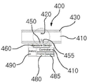
도 2 및 도 3을 참조하면, 본 발명의 일 실시예에 따른 자가호흡 모니터링 장치는 기도유지장치의 튜브 단부에 어뎁터 방식으로 착탈가능하게 설치된다. 즉 호흡 모니터링부(400)는 환자의 호흡이 통과하도록 내부에 통로(410)가 형성된 관체부(430)를 포함한다. 2 and 3, the self-breathing monitoring device according to an embodiment of the present invention is detachably installed to the tube end of the airway maintenance device in an adapter manner. That is, the
여기서 관체부(430)의 내주면에는 내측으로 일정길이 돌출된 단턱부(420)가 형성된다. 즉 단턱부(420)는 환형의 형태로 관체부(430)의 내주면에서 내측으로 일정길이 연장형성된다. 또한 관체부(430)의 내부에는 단턱부(420)를 기준으로 제1 센싱홀(450)과 제2 센싱홀(455)이 관통형성된다. 즉 제1 센싱홀(450)과 제2 센싱홀(455)은 관체부(430)의 내부에서 외부로 수직방향으로 관통형성된 구성으로 제공된다. Here, the inner circumferential surface of the
또한 제1 센싱홀(450)과 제2 센싱홀(455)은 각각 압력센서(460)가 연통되어 이 압력센서(460)를 통해 관체부(430) 내의 공기 압력을 측정함으로써 호흡량(들숨과 날숨시 호흡량)을 측정할 수 있다. 이때 압력센서(460)에는 컨트롤러(470)가 연결되고, 이 컨트롤러(470)에는 측정된 호흡량을 외부로 표시할 있도록 알림부재로서 시각적으로 표시하기 위한 디스플레이부(480)나 음향으로 알리기 위한 알람부(485)가 연결될 수 있다. 아울러 호흡 모니터링부(400)에는 압력센서(460)와 컨트롤러(470)에 전원을 제공하기 위한 베터리부(490)가 제공된다. In addition, each of the first and
이와 같이 구성된 본 발명의 자가호흡 모니터링 장치(400)는 호흡기의 감염을 막기 위해 기도유지장치의 튜브의 말단에 어댑터방식으로 착탈이 가능하게 설치된다. 또한 관체부(430)의 내주면에 형성된 단턱부(420)에 의해 오리피스에 따른 압력차를 발생시키고, 환자의 들숨과 날숨에 따른 관체부(430)의 내부 압력차이를 제1 센싱홀(450)과 제2 센싱홀(455)에 연결된 압력센서(460)를 통해 측정할 수 있다.The self-
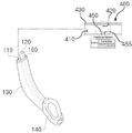
도 4a 및 도 4b는 내시경용 기도유지장치를 나타내는 것으로, 이 내시경용 기도유지장치에는 본 발명의 자가호흡 모니터링 장치(400)가 착탈가능하게 연결된다. 4A and 4B show an endoscope airway holding device, and the endoscope airway holding device is detachably connected to the self-
구체적으로 내시경용 기도유지장치는 환자의 식도와 연통되는 기도 연결관(110)과, 환자의 식도와 연통되며 내시경의 출입이 가능한 내시경 삽입로(120)를 포함한다. 아울러 내부 또는 외부에 기도 연결관(110) 및 내시경 삽입로(120)가 형성되며, 일측에 커프(cuff) 형상의 돌출부가 형성되고 타측에 기도 연결관(110) 및 내시경 삽입로(120)의 통로가 형성된 본체(130)를 포함한다. 이때 본체(130)의 말단에는 사용시 기관 삽입을 위한 삽입부(140)를 포함한다. Specifically, the endoscope airway maintenance apparatus includes an
한편 내시경용 기도유지장치는 종래의 기도유지장치 중에 IGELTM(영국의 Intersurgical社의 제품)이 적용될 수 있다. On the other hand, the endoscope airway holding device may be applied to the IGEL TM (product of Intersurgical Co., UK) of the conventional airway holding device.
상기한 구성에 있어서 기도 연결관(110)은 환자의 기도와 연통되어 환자에게 산소 또는 공기를 공급하는 역할을 한다. 또한 내시경 삽입로(120)는 내시경의 출입을 가능하게 하는 통로로서의 역할을 한다. 또한 내시경 삽입로(120)는 본체(130)의 내부에 내시경 삽입관 형태로 형성되거나 본체(130)의 외부에 형성될 수도 있다. In the above configuration, the
상기한 구성에 있어서 본체(130)는 내부 또는 외부에 기도 연결관(110) 및 내시경 삽입로(120)를 포함하며, 일측에 커프(cuff) 형상의 돌출부가 형성되고, 타측에 기도 연결관(110) 및 내시경 삽입로(120)는 적합한 직경을 갖도록 배치된다. 즉 기도 연결관(110)과 내시경 삽입로(120)는 기도유지장치의 전체 부피를 최소화 할 수 있는 방식으로 제조될 수 있다. 또한 본체(130)의 외부에는 걸림턱(150)이 형성되어 기도유지장치를 성문상부에 고정시키는 역할을 한다. In the above configuration, the
한편 기도유지장치는 기관 내 물질을 흡입하기 위한 흡입관(160)을 본 발명의 본체(130)의 내부 또는 외부에 추가적으로 포함한다. 이때 흡입관(160)은 1개 또는 복수개의 구멍을 구비한다. Meanwhile, the airway maintaining apparatus further includes a
이러한 구성을 갖는 기도유지장치의 기도 연결관(110)에는 자가호흡 모니터링 장치(400)가 착탈가능하게 설치된다. 구체적으로 도 4b와 같이 자가호흡 모니터링 장치(400)의 관체(430)에는 기도 연결관(110)의 단부에 연결된다. 이에 따라 기도 연결관(110)을 통해 전달되는 환자의 호흡량은 자가호흡 모니터링 장치(400)의 복수의 센싱홀(450,455)을 통한 압력센서(460)에 의해 측정이 이루어질 수 있다. A self-breathing
즉, 도 5a 내지 5d는 호흡 모니터링부의 호흡 검출에 대한 시뮬레이션 그래프를 나타낸 것으로 이를 참조해 보면 다음과 같다. That is, FIGS. 5A to 5D show simulation graphs for respiratory detection of the respiratory monitoring unit.
이와 같이 본 발명은 기도유지장치의 말단에 연결된 자가호흡 모니터링 장치(400)의 단턱부(420)를 기준으로 형성된 오리피스 작용에 따른 압력의 차이를 측정하고, 이를 통해 환자의 들숨과 날숨을 실시간으로 모니터링할 수 있고, 이 측정된 값에 근거하여 시술자에게 알람(소리 또는 시각적 표시)을 표시할 수 있다. 이와 같이 본 발명의 자가호흡 모니터링 장치(400)를 통해 환자의 자가호흡을 실시간으로 확인할 수 있다. As described above, the present invention measures the pressure difference according to the orifice action formed on the
이와 같이 본 발명은 내시경 프로브를 환자의 구강을 통하여 소화기 계통으로 삽입하는 과정에서 내시경 시술자가 자가호흡 모니터링 장치(400)를 통해 환자가 자율 호흡을 하는지에 대한 여부를 확인할 수 있다. As described above, the present invention can confirm whether the endoscope operator performs autonomous breathing through the self-breathing
즉, 본 발명은 환자의 들숨 시에 단턱부(420)을 기준으로 전방측에 배치된 제2 센싱홀(455)을 통해 측정되는 공기압이 제1 센싱홀(450)을 통해 측정되는 압력보다 높게 된다. 반대로 환자의 날숨 시에는 단턱부(420)을 기준으로 후방에 배치된 제1 센싱홀(450)을 통해 측정되는 공기압이 제2 센싱홀(455)을 통해 측정되는 공기압보다 높게 된다. That is, according to the present invention, the air pressure measured through the
이와 같이 자가호흡 모니터링 장치(400)는 관체부(430)의 내주면에 환형의 형태로 형성된 단턱부(420)에 의해 오리피스 형상이 발생되고 이러한 작용에 의해 센싱홀(450 또는 455)의 압력차이는 컨트롤러(470)에 의해 디스플레이부(480)나 알람부(485)로 표시될 수 있다. 따라서 환자가 자기 호흡하는 지에 대한 여부를 실시간으로 확인할 수 있다. As described above, the self-breathing
이상에서는 본 발명을 특정의 실시예에 대해서 도시하고 설명하였지만, 본 발명은 상술한 실시예에만 한정되는 것은 아니며, 본 발명이 속하는 기술분야에서 통상의 지식을 가진 자라면 이하의 청구범위에 기재된 본 발명의 기술적 사상의 요지를 벗어나지 않는 범위에서 얼마든지 다양하게 변경하여 실시할 수 있을 것이다. While the invention has been shown and described with respect to specific embodiments thereof, the invention is not limited to only the embodiments described above, and those of ordinary skill in the art to which the invention pertains may find the invention described in the claims below Various changes may be made without departing from the spirit of the technical idea of the invention.
400: 자가호흡 모니터링 장치
410: 통로
420: 단턱부
430: 관체부
450: 제1 센싱홀
455: 제2 센싱홀
460: 압력센서
470: 컨트롤러
480: 디스플레이부
485: 알람부400: self-breathing monitoring device
410: passage
420: step
430: tube
450: first sensing hole
455: second sensing hole
460: pressure sensor
470: controller
480: display unit
485: alarm unit
Claims (3)
환자의 호흡시 공기가 통과하도록 내부에 통로가 형성된 관체부;
상기 관체부의 내주면에서 내측방향으로 일정높이 돌출형성된 단턱부;
상기 단턱부를 기준으로 양측에 각각 위치하고 각각 상기 관체부를 수직방향으로 관통하도록 형성된 복수의 센싱홀부; 및
상기 센싱홀부에 연결되어 상기 단턱부를 기준으로 하여 상기 관체부 내의 압력차를 검출하는 압력센서를 포함하여 이루어진 것을 특징으로 하는 자가호흡 모니터링 장치. Self-breathing monitoring device connected to the airway secured device to check the patient's self-breathing,
A tubular portion having a passage formed therein to allow air to pass through when the patient breathes;
A stepped portion protruding a predetermined height inwardly from an inner circumferential surface of the tubular portion;
A plurality of sensing holes disposed on both sides of the stepped portion and respectively formed to penetrate the tubular portion in a vertical direction; And
And a pressure sensor connected to the sensing hole to detect a pressure difference in the tubular part based on the stepped part.
상기 압력센서에 전기적으로 연결되어 상기 압력차를 표시하는 디스플레이부 또는 알람부 중 적어도 하나를 더 포함하여 이루어진 것을 특징으로 하는 자가호흡 모니터링 장치. The method of claim 1,
And at least one of a display unit or an alarm unit electrically connected to the pressure sensor to display the pressure difference.
상기 관체부는 상기 기도확보장치의 호흡라인에 착탈이 가능하게 설치된 것을 특징으로 하는 자가호흡 모니터링 장치.
The method of claim 1,
The tubular portion is a self-breathing monitoring device, characterized in that installed detachable to the breathing line of the airway ensuring device.
Priority Applications (1)
| Application Number | Priority Date | Filing Date | Title |
|---|---|---|---|
| KR1020180103651A KR20200025776A (en) | 2018-08-31 | 2018-08-31 | Apparatus for monitoring self respiration |
Applications Claiming Priority (1)
| Application Number | Priority Date | Filing Date | Title |
|---|---|---|---|
| KR1020180103651A KR20200025776A (en) | 2018-08-31 | 2018-08-31 | Apparatus for monitoring self respiration |
Publications (1)
| Publication Number | Publication Date |
|---|---|
| KR20200025776A true KR20200025776A (en) | 2020-03-10 |
Family
ID=69801016
Family Applications (1)
| Application Number | Title | Priority Date | Filing Date |
|---|---|---|---|
| KR1020180103651A Ceased KR20200025776A (en) | 2018-08-31 | 2018-08-31 | Apparatus for monitoring self respiration |
Country Status (1)
| Country | Link |
|---|---|
| KR (1) | KR20200025776A (en) |
Cited By (2)
| Publication number | Priority date | Publication date | Assignee | Title |
|---|---|---|---|---|
| KR20210008956A (en) * | 2019-07-15 | 2021-01-26 | 주식회사 한유메딕스 | Larynx mask apparatus |
| KR20220028697A (en) | 2020-08-31 | 2022-03-08 | 전남대학교산학협력단 | Mask-attached breath monitoring apparatus and system |
-
2018
- 2018-08-31 KR KR1020180103651A patent/KR20200025776A/en not_active Ceased
Cited By (2)
| Publication number | Priority date | Publication date | Assignee | Title |
|---|---|---|---|---|
| KR20210008956A (en) * | 2019-07-15 | 2021-01-26 | 주식회사 한유메딕스 | Larynx mask apparatus |
| KR20220028697A (en) | 2020-08-31 | 2022-03-08 | 전남대학교산학협력단 | Mask-attached breath monitoring apparatus and system |
Similar Documents
| Publication | Publication Date | Title |
|---|---|---|
| US11801356B2 (en) | Control of mechanical ventilation based on laryngopharyngeal muscle activity | |
| US10898669B2 (en) | Carbon dioxide inhalation treatment device for central sleep apnea | |
| US5937858A (en) | Oro/nasopharyngeal airway for administering/sampling inhalent/expired gases | |
| CN1895691B (en) | Method and device for nasal cavity oxygen supply, especially airflow synchronized neonatal supplemental oxygen supply | |
| US20130281885A1 (en) | Device with external pressure sensors for enhancing patient care and methods of using same | |
| US20080255467A1 (en) | Method and system for detecting breathing tube occlusion | |
| WO1999029358A1 (en) | Oro/nasopharyngeal airway | |
| US12239785B2 (en) | Ventilation devices and systems and methods of using same | |
| US10010690B1 (en) | Endotracheal tube apparatus | |
| Stierli et al. | Insights from an interprofessional post-COVID-19 rehabilitation unit: a speech and language therapy and respiratory medicine perspective | |
| US20120203101A1 (en) | Methods for optoacoustic guidance and confirmation of placement of novel indwelling medical apparatus | |
| KR20200025778A (en) | Apparatus for free airway having respiratory monitoring function | |
| KR20200025776A (en) | Apparatus for monitoring self respiration | |
| KR20210008956A (en) | Larynx mask apparatus | |
| US20070062540A1 (en) | Respiratory monitoring apparatus and related method | |
| WO2011068741A1 (en) | Sensing endotracheal tube location | |
| CN215083679U (en) | Novel painless scope anaesthetic mask | |
| CN216169264U (en) | Oropharynx breather pipe convenient to monitor end-expiratory carbon dioxide concentration | |
| CN213252182U (en) | a nasopharyngeal airway | |
| CN205672028U (en) | A kind of centric sleep apnea carbon dioxide inhalation therapy device | |
| US20250367393A1 (en) | Tracheostomy tube monitoring accessory and uses thereof | |
| CN217645644U (en) | Fixing-free laryngeal mask | |
| CN210057050U (en) | Tracheal catheter for adding medicine, sucking and monitoring nerve and body temperature | |
| Robb | An overview of ventilator observations | |
| CN113425964A (en) | Special visual endotracheal tube of neonate |
Legal Events
| Date | Code | Title | Description |
|---|---|---|---|
| PA0109 | Patent application |
Patent event code: PA01091R01D Comment text: Patent Application Patent event date: 20180831 |
|
| PG1501 | Laying open of application | ||
| A201 | Request for examination | ||
| PA0201 | Request for examination |
Patent event code: PA02012R01D Patent event date: 20210831 Comment text: Request for Examination of Application Patent event code: PA02011R01I Patent event date: 20180831 Comment text: Patent Application |
|
| E902 | Notification of reason for refusal | ||
| PE0902 | Notice of grounds for rejection |
Comment text: Notification of reason for refusal Patent event date: 20230118 Patent event code: PE09021S01D |
|
| E601 | Decision to refuse application | ||
| PE0601 | Decision on rejection of patent |
Patent event date: 20230406 Comment text: Decision to Refuse Application Patent event code: PE06012S01D Patent event date: 20230118 Comment text: Notification of reason for refusal Patent event code: PE06011S01I |