KR20200002895A - Ramping inserts and ramping tools with non-benign cutting geometry - Google Patents
Ramping inserts and ramping tools with non-benign cutting geometry Download PDFInfo
- Publication number
- KR20200002895A KR20200002895A KR1020197032898A KR20197032898A KR20200002895A KR 20200002895 A KR20200002895 A KR 20200002895A KR 1020197032898 A KR1020197032898 A KR 1020197032898A KR 20197032898 A KR20197032898 A KR 20197032898A KR 20200002895 A KR20200002895 A KR 20200002895A
- Authority
- KR
- South Korea
- Prior art keywords
- ramping
- edge
- insert
- central plane
- plane
- Prior art date
- Legal status (The legal status is an assumption and is not a legal conclusion. Google has not performed a legal analysis and makes no representation as to the accuracy of the status listed.)
- Granted
Links
Images




Classifications
-
- B—PERFORMING OPERATIONS; TRANSPORTING
- B23—MACHINE TOOLS; METAL-WORKING NOT OTHERWISE PROVIDED FOR
- B23B—TURNING; BORING
- B23B27/00—Tools for turning or boring machines; Tools of a similar kind in general; Accessories therefor
-
- B—PERFORMING OPERATIONS; TRANSPORTING
- B23—MACHINE TOOLS; METAL-WORKING NOT OTHERWISE PROVIDED FOR
- B23C—MILLING
- B23C5/00—Milling-cutters
- B23C5/16—Milling-cutters characterised by physical features other than shape
- B23C5/20—Milling-cutters characterised by physical features other than shape with removable cutter bits or teeth or cutting inserts
- B23C5/22—Securing arrangements for bits or teeth or cutting inserts
-
- B23C5/2221—
-
- B—PERFORMING OPERATIONS; TRANSPORTING
- B23—MACHINE TOOLS; METAL-WORKING NOT OTHERWISE PROVIDED FOR
- B23C—MILLING
- B23C5/00—Milling-cutters
- B23C5/16—Milling-cutters characterised by physical features other than shape
- B23C5/20—Milling-cutters characterised by physical features other than shape with removable cutter bits or teeth or cutting inserts
- B23C5/22—Securing arrangements for bits or teeth or cutting inserts
- B23C5/2204—Securing arrangements for bits or teeth or cutting inserts with cutting inserts clamped against the walls of the recess in the cutter body by a clamping member acting upon the wall of a hole in the insert
- B23C5/2208—Securing arrangements for bits or teeth or cutting inserts with cutting inserts clamped against the walls of the recess in the cutter body by a clamping member acting upon the wall of a hole in the insert for plate-like cutting inserts
- B23C5/2213—Securing arrangements for bits or teeth or cutting inserts with cutting inserts clamped against the walls of the recess in the cutter body by a clamping member acting upon the wall of a hole in the insert for plate-like cutting inserts having a special shape
-
- B—PERFORMING OPERATIONS; TRANSPORTING
- B23—MACHINE TOOLS; METAL-WORKING NOT OTHERWISE PROVIDED FOR
- B23C—MILLING
- B23C2200/00—Details of milling cutting inserts
- B23C2200/04—Overall shape
- B23C2200/0494—Rectangular
-
- B—PERFORMING OPERATIONS; TRANSPORTING
- B23—MACHINE TOOLS; METAL-WORKING NOT OTHERWISE PROVIDED FOR
- B23C—MILLING
- B23C2200/00—Details of milling cutting inserts
- B23C2200/08—Rake or top surfaces
- B23C2200/085—Rake or top surfaces discontinuous
-
- B—PERFORMING OPERATIONS; TRANSPORTING
- B23—MACHINE TOOLS; METAL-WORKING NOT OTHERWISE PROVIDED FOR
- B23C—MILLING
- B23C2200/00—Details of milling cutting inserts
- B23C2200/12—Side or flank surfaces
- B23C2200/125—Side or flank surfaces discontinuous
-
- B—PERFORMING OPERATIONS; TRANSPORTING
- B23—MACHINE TOOLS; METAL-WORKING NOT OTHERWISE PROVIDED FOR
- B23C—MILLING
- B23C2200/00—Details of milling cutting inserts
- B23C2200/12—Side or flank surfaces
- B23C2200/125—Side or flank surfaces discontinuous
- B23C2200/126—Side or flank surfaces discontinuous stepped
-
- B—PERFORMING OPERATIONS; TRANSPORTING
- B23—MACHINE TOOLS; METAL-WORKING NOT OTHERWISE PROVIDED FOR
- B23C—MILLING
- B23C2200/00—Details of milling cutting inserts
- B23C2200/28—Angles
- B23C2200/281—Negative rake angles
-
- B23C2200/283—
-
- B—PERFORMING OPERATIONS; TRANSPORTING
- B23—MACHINE TOOLS; METAL-WORKING NOT OTHERWISE PROVIDED FOR
- B23C—MILLING
- B23C2200/00—Details of milling cutting inserts
- B23C2200/28—Angles
- B23C2200/284—Negative clearance angles
-
- B23C2200/286—
-
- B—PERFORMING OPERATIONS; TRANSPORTING
- B23—MACHINE TOOLS; METAL-WORKING NOT OTHERWISE PROVIDED FOR
- B23C—MILLING
- B23C2200/00—Details of milling cutting inserts
- B23C2200/36—Other features of the milling insert not covered by B23C2200/04 - B23C2200/32
- B23C2200/367—Mounted tangentially, i.e. where the rake face is not the face with largest area
Landscapes
- Engineering & Computer Science (AREA)
- Mechanical Engineering (AREA)
- Milling Processes (AREA)
- Ceramic Products (AREA)
Abstract
양면, 색인 가능, 비양성 램핑 인서트는 3차원 유클리드 공간의 제 1, 제 2 및 제 3 축 각각에 대해 180도 회전 대칭을 갖는다. 상기 램핑 인서트는 2개의 제 1 표면 및 그 사이에 연장하는 인서트 외주 표면을 포함한다. 상기 램핑 인서트는 4개의 커팅 부분을 포함하고, 각각은 주 커팅 에지, 코너 커팅 에지를 통해 횡방향으로 연결되는 와이퍼 에지 및 제 1 축에 평행한 시야에서 와이퍼 에지로부터 횡방향으로 연장되는 램핑 에지를 포함한다. 각각의 외주 표면은 4개의 비-양성 램핑 릴리프 표면을 포함하고, 각각의 램핑 에지로부터 제 2 및 제 3 축에 의해 정의되는 제 1 중앙 평면을 향하여 연장되나 이를 넘어 연장되지는 않는다.The double-sided, indexable, non-positive ramping insert has 180 degree rotational symmetry about each of the first, second and third axes of the three-dimensional Euclidean space. The ramping insert comprises two first surfaces and an insert peripheral surface extending therebetween. The ramping insert comprises four cutting parts, each of which comprises a main cutting edge, a wiper edge connected laterally through the corner cutting edge and a ramping edge extending laterally from the wiper edge in a field parallel to the first axis. Include. Each outer circumferential surface comprises four non-positive ramping relief surfaces and extends from each ramping edge toward the first central plane defined by the second and third axes, but not beyond.
Description
본 출원의 주제는 램핑 도구에 관한 것이다. 특히, 그것은 램핑 커팅 에지을 가진 밀링 또는 램핑 인서트에 관한 것이다.The subject of the present application relates to a ramping tool. In particular, it relates to milling or ramping inserts with ramping cutting edges.
램핑 커팅 에지 또는 램핑 능력을 포함하지 않는 범용 밀링 분야의 인서트가 공개된다. 상기 램핑 인서트는 접지면이 거의 없다. 즉, 램핑 인서트는 크기에 맞게 가압되어 있으며, 이는 또한 커팅 에지를 포함한 모든 에지가 충분히 정확하게 가압되어 연마가 필요하지 않다는 것을 의미한다.Inserts in general-purpose milling applications that do not include ramping cutting edges or ramping capabilities are disclosed. The ramping insert has little ground plane. That is, the ramping insert is pressed to size, which also means that all the edges, including the cutting edges, are pressed sufficiently precisely that no polishing is necessary.
상술한 크기에 맞는 가압 장점을 제외하고, 가압 방법은 오직 단일 축을 따라 다이/몰드/펀치 운동을 포함한다. 구체적으로, US7560068에서 개시된 분할 다이 방법이 사용된다. 상기 단일 축 타입 가압 방법은 낮은 수의 다이/펀치 부품을 가능하게 하고, 생산 간소화를 증가 시키며, 따라서 생산 비용을 상당히 낮춘다. 하기하는 바와 같이, 이러한 장점은 유지되며, 공지된 램핑 인서트에 대한 램핑 기능을 가능하게 하는 새로운 특성 조합 및 형상을 도입한다.Except for the pressurization advantages that fit the size described above, the pressurization method only includes die / mold / punch motion along a single axis. Specifically, the split die method disclosed in US7560068 is used. The single axis type pressurization method enables a low number of die / punch parts, increases production simplification, and thus significantly lowers production costs. As described below, this advantage is maintained and introduces new feature combinations and shapes that enable the ramping function for known ramping inserts.
본 출원의 주제의 제 1 양태에 따라, 3차원 유클리드 공간에서 각각 180도 회전 대칭인 제 1, 제 2 및 제 3 축, 상기 제 2 및 제 3 축에 의해 정의된 제 1 중앙 평면, 상기 제 1 및 제 3 축에 의해 정의된 제 2 중앙 평면(YP) 및 상기 제 1축 및 제 2축에 의해 정의된 제 3 중앙 평면을 갖는 양면, 색인 가능하고 비양성 램핑 인서트가 제공된다.According to a first aspect of the subject matter of the present application, a first central plane defined by the first, second and third axes, the second and third axes, each of which is 180 degrees rotationally symmetric in three-dimensional Euclidean space, the first A double-sided, indexable, and non-positive ramping insert is provided having a second central plane YP defined by the first and third axes and a third central plane defined by the first and second axes.
상기 램핑 인서트는 상기 제 1 중앙 평면의 대향측면에 위치하는 2개의 제 1 표면과, 상기 제 1 표면들 사이에서 연장되고 외주 에지에서 각각의 제 1 표면과 교차하는 인서트 외주 표면을 포함하고,The ramping insert comprises two first surfaces located on opposite sides of the first central plane, and an insert outer peripheral surface extending between the first surfaces and intersecting each first surface at an outer peripheral edge thereof,
각 제 1 표면은 두 개의 상승 코너와 두 개의 하강 코너를 포함하며, 상승 코너는 하강 코너보다 제 1 중앙 평면에서 더 멀리 있고;Each first surface includes two rising corners and two falling corners, the rising corners being farther from the first central plane than the falling corners;
인서트 외주 표면은 2개의 제 2 표면 및 그 사이에 연장되는 2개의 제 3 표면을 포함하고,The insert outer circumferential surface comprises two second surfaces and two third surfaces extending therebetween,
각각의 제 1 표면은 정확히 두 개의 반대 커팅 부분을 포함하고,Each first surface comprises exactly two opposite cutting portions,
각각의 커팅 부분은:Each cutting part is:
상기 제 1 표면과 제 2 표면의 교차부에 형성되는 주 커팅 에지;A major cutting edge formed at the intersection of the first surface and the second surface;
상기 상승 코너 중 하나에 있는 코너 커팅 에지; 및A corner cutting edge at one of the rising corners; And
상기 코너 커팅 에지을 통해 상기 주 커팅 에지과 연결되는 와이퍼 에지를 포함하고,A wiper edge connected with said main cutting edge through said corner cutting edge,
각각의 커팅 부분은 제 1 축에 평행한 시야에서 와이퍼 에지로부터 횡방향으로 연장되는 램핑 에지를 포함하고; 및Each cutting portion comprises a ramping edge extending transversely from the wiper edge in a field of view parallel to the first axis; And
각각의 제 3 표면은 오직 두 개의 비양성 램핑 릴리프 표면을 포함하고, 각각의 램핑 릴리프 표면은 각각의 램핑 에지로부터 제 1 중앙 평면을 향하여 연장되나 이를 넘어서 연장되지는 않는다.Each third surface includes only two aprotic ramping relief surfaces, each ramping relief surface extending from the respective ramping edge toward the first central plane but not beyond.
본 출원의 주제의 제 3 양태에 따라, 서로 대향된 가공 및 결합 단부를 갖는 램핑 공구가 추가로 제공되며, 여기서 상기 가공 단부는 포켓 및 그 내부에 결합된 램핑 인서트를 포함한다.According to a third aspect of the subject matter of the present application, there is further provided a ramping tool having opposite machining and mating ends, wherein the machining end comprises a pocket and a ramping insert engaged therein.
단독 또는 조합으로 다음 특징 중 어느 것이든 본 출원의 주제의 상기 양태에 적용될 수 있다.Any of the following features, alone or in combination, may be applied to the above aspects of the subject matter of the present application.
각각의 제 1 표면 상에서, 제 1 커팅 부분의 각 램핑 에지는 부 코너 에지를 통해 제 2 커팅 부분의 주 커팅 에지에 연결된다.On each first surface, each ramping edge of the first cutting portion is connected to the main cutting edge of the second cutting portion via the secondary corner edge.
각 외주 에지에서, 각 부 코너 에지는 주 코너 에지 중 어느 것보다 제 1 중앙 평면에 더 가깝게 위치된다.At each outer edge, each minor corner edge is located closer to the first center plane than any of the major corner edges.
각각의 제 1 표면에서, 부 코너 에지는 코너 커팅 에지보다 제 1 및 제 2 축에 의해 정의된 제 3 중앙 평면에 더 가깝다.At each first surface, the secondary corner edge is closer to the third central plane defined by the first and second axes than the corner cutting edge.
제 1 축에 평행한 시야에서, 상기 램핑 에지는 상기 제 1 중앙 평면과 상기 제 3 표면 사이에 형성된 교차 라인으로부터 적어도 부분적으로 이격된다.In a field parallel to the first axis, the ramping edge is at least partially spaced from an intersecting line formed between the first central plane and the third surface.
제 1 축에 평행한 시야에서, 제 1 중앙 평면의 가까운 측면에 위치한 제 3 표면의 모든 지점은 가시적이거나 시점에 더 가까운 외주 변부와 일치한다.In a view parallel to the first axis, all points of the third surface located on the near side of the first central plane coincide with the outer periphery that is visible or closer to the viewpoint.
클램핑 홀은 제 1 또는 제 2 표면 사이에서 연장되고 개방된다.The clamping hole extends and opens between the first or second surface.
각각의 제 1 표면은 제 1 중간 평면과 평행한 제 1 인접 표면을 포함한다.Each first surface includes a first adjacent surface parallel to the first intermediate plane.
각각의 제 1 표면은 제 1 중앙 평면에 대해 횡방향인 제 1 인접 서브-표면들을 포함할 수 있다.Each first surface may include first adjacent sub-surfaces transverse to the first central plane.
각각의 제 2 표면은 제 1 및 제 3 축에 의해 정의된 제 2 중앙 평면에 평행한 평면형 제 2 인접 표면을 포함할 수 있다.Each second surface may comprise a planar second adjacent surface parallel to a second central plane defined by the first and third axes.
각각의 제 3 표면은 제 1 및 제 2 축에 의해 정의된 제 3 중앙 평면에 평행한 평면형 제 3 인접 표면을 포함할 수 있다.Each third surface may comprise a planar third adjacent surface parallel to a third central plane defined by the first and second axes.
각각의 제 2 표면은 두 개의 주요 릴리프 표면을 포함하며, 각각은 제 1 및 제 3 축에 의해 정의된 제 2 중앙 평면에 가로 방향으로 연관된 주 커팅 에지로부터 연장된다.Each second surface comprises two major relief surfaces, each extending from a major cutting edge associated transversely to a second central plane defined by the first and third axes.
각각의 제 3 표면은 2개의 와이퍼 릴리프 표면을 포함하며, 각각은 연관된 와이퍼 에지로부터 제 1 중앙 평면을 향해 연장된다.Each third surface comprises two wiper relief surfaces, each extending from the associated wiper edge towards the first central plane.
각각의 제 3 표면은 각각의 와이퍼 에지로부터 제 1 중앙 평면을 향해 연장되는 와이퍼 릴리프 표면들 및 와이퍼 릴리프 표면들 사이에서 연장되는 제 3 인접 표면을 포함한다. 와이퍼 릴리프 표면은 비접지 표면을 구성할 수 있다.Each third surface includes wiper relief surfaces extending from each wiper edge toward the first central plane and a third adjacent surface extending between the wiper relief surfaces. The wiper relief surface may constitute an ungrounded surface.
각각의 램핑 릴리프 표면은 수직이거나 제 1 및 제 2 축에 의해 정의된 제 3 중앙 평면을 갖는 예각 내부 램핑 릴리프 각도를 형성한다.Each ramping relief surface is perpendicular or forms an acute internal ramping relief angle having a third central plane defined by the first and second axes.
각각의 제 3 표면은 각각의 와이퍼 에지로부터 제 1 중앙 평면을 향해 연장되는 와이퍼 릴리프 표면을 포함하고, 여기서 와이퍼 릴리프 표면 및 램핑 릴리프 표면은 동일 평면에 있지 않는다.Each third surface includes a wiper relief surface extending from each wiper edge towards the first central plane, wherein the wiper relief surface and the ramping relief surface are not coplanar.
제 1 축에 평행한 시야에서, 와이퍼 에지로부터 출발하는 램핑 에지를 따라 진행할 때, 각각의 연속적인 포인트는 제 1 및 제 2 축에 의해 정의된 제 3 중앙 평면에 이전 축보다 더 가깝게 위치된다.In a view parallel to the first axis, when running along the ramping edge starting from the wiper edge, each successive point is located closer than the previous axis to the third central plane defined by the first and second axes.
제 1 축에 평행한 시야에서, 램핑 에지는 직선으로 나타나고, 제 1 및 제 2 축에 의해 정의된 제 3 중앙 평면을 갖는 예각 램핑 각도를 형성한다.In the field of view parallel to the first axis, the ramping edges appear straight and form an acute ramping angle with a third center plane defined by the first and second axes.
상기 램핑 에지는 연속적이다.The ramping edge is continuous.
제 2 중앙 평면은 제 1 및 제 3 축에 의해 정의되고, 제 3 중앙 평면은 제 1 및 제 2 축에 의해 정의되며, 제 2 중앙 평면에 평행하게 취한 제 3 면의 임의의 단면에서, 제 1 중앙 평면으로부터 각 제 3 면을 따라 진행할 때, 각각의 연속점은 제 3 중앙 평면으로부터 동일 거리 또는 그 앞의 점에 대해 제 3 중앙 평면에 위치한다.The second central plane is defined by the first and third axes, and the third central plane is defined by the first and second axes, and in any cross section of the third face taken parallel to the second central plane, When traveling along each third plane from the first center plane, each continuous point is located in the third center plane with respect to a point at or equal to the distance from the third center plane.
제 2 중앙 평면은 제 1 및 제 3 축에 의해 정의되고, 제 3 중앙 평면은 제 1 및 제 2 축에 의해 정의되며, 제 3 중앙 평면에 평행하게 취한 제 2 표면의 임의의 단면에서, 제 1 중앙 평면으로부터 멀어지는 각 제 2 표면을 따라 진행할 때, 각각의 연속점은 제 2 중앙 평면으로부터 동일 거리 또는 그 이전 지점에 대해 제 2 중앙 평면에 위치한다.The second central plane is defined by the first and third axes, the third central plane is defined by the first and second axes, and in any cross section of the second surface taken parallel to the third central plane, Proceeding along each second surface away from the first central plane, each continuous point is located in the second central plane about the same distance or earlier point from the second central plane.
주 커팅 에지는 램핑 에지보다 길고 램핑 에지는 와이퍼 에지보다 길다.The main cutting edge is longer than the ramping edge and the ramping edge is longer than the wiper edge.
상기 램핑 링 인서트는 적어도 180도 커팅 에지 회전 대칭을 갖는다.The ramping ring insert has at least 180 degree cutting edge rotational symmetry.
회전 대칭은 비-기능 형상을 포함하지 않는다.Rotational symmetry does not include non-functional shapes.
회전 대칭에는 칩 파괴 또는 편향 표면이 포함되지 않는다.Rotational symmetry does not include chip breaking or deflection surfaces.
램핑 인서트은 공작물에서 정확히 90도 견부를 밀링하도록 구성된다.The ramping insert is configured to mill exactly 90 degrees shoulders on the workpiece.
제 1 축에 평행한 시야에서, 램핑 에지의 임의의 점에 접하는 직선 접선은 제 3 중앙 평면과 20도보다 작은 램핑 각도를 형성한다.In the field of view parallel to the first axis, the straight tangent tangent to any point of the ramping edge forms a ramping angle of less than 20 degrees with the third central plane.
와이퍼 에지로부터 램핑 에지를 따라 진행할 때, 램핑 에지는 제 1 중앙 평면에 근접성을 증가시킨다.When traveling along the ramping edge from the wiper edge, the ramping edge increases proximity to the first center plane.
각각의 포켓은, 스크류산 스크류 홀이 뚫려 있는 제 2 포켓 인접 표면, 제 1 포켓 인접 표면으로부터 횡방향으로 연장되는 제 1 및 제 3 포켓 인접 표면, 및 포켓 내에 램핑 인서트를 클램핑하도록 구성된 클램핑 스크류를 포함할 수 있다.Each pocket includes a second pocket adjacent surface through which threaded screw holes are drilled, first and third pocket adjacent surfaces extending laterally from the first pocket adjacent surface, and a clamping screw configured to clamp the clamping insert in the pocket. It may include.
상기 램핑 공구의 조립 위치에서, 상기 제 1 인접 표면은 상기 제 1 포켓 인접 표면과 맞닿고, 상기 제 2 인접 표면은 상기 제 2 포켓 인접 표면과 맞닿고, 상기 제 3 인접 표면은 상기 제 3 포켓 인접 표면과 맞닿고, 상기 클램핑 스크류는 상기 스크류 홀에 스크류결합되어 상기 클램핑 보어 내에 위치된다.In the assembled position of the ramping tool, the first adjacent surface abuts the first pocket adjacent surface, the second adjacent surface abuts the second pocket adjacent surface, and the third adjacent surface is the third pocket. In contact with an adjacent surface, the clamping screw is screwed into the screw hole and positioned in the clamping bore.
본 출원의 주제를 더 잘 이해하고 실제로 어떻게 수행 될 수 있는지를 보여주기 위해, 첨부된 도면을 참조한다.To better understand the subject matter of the present application and to show how it can be carried out in practice, reference is made to the accompanying drawings.
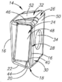
도 1은 접선 램핑 인서트의 등각 사시도.
도 2는 도 1의 램핑 인서트의 제 1 표면의 평면도.
도 3은 도 1의 램핑 인서트의 제 3 표면의 평면도.
도 4는 도 1의 외부로 개방되는 클램핑 홀을 도시하는 램핑 인서트의 제 2 표면의 평면도.
도 5는 제 1 표면으로 개방된 클램핑 홀을 나타내는 도 1의 램핑 인서트의 방사형 실시예의 등각도.
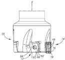
도 6은 조립된 위치에서 포켓에 고정되는 도 1의 램핑 인서트의 또 다른 실시예를 갖는 램핑 공구의 등각 사시도.
도 7은 도 6의 램핑 도구의 측면도.
도 8은 그림의 램핑 도구의 축 방향 저면도.
도 9는 도 6의 램핑 인서트의 제 3 표면의 평면도.
도 10은 램핑 릴리프 표면과 와이퍼 릴리프 표면 위를 통과하는 도 9의 X-X 선을 따른 단면도.1 is an isometric view of a tangential ramping insert.
2 is a plan view of a first surface of the ramping insert of FIG.
3 is a plan view of a third surface of the ramping insert of FIG.
4 is a plan view of a second surface of the ramping insert showing the clamping hole opening outward of FIG.
5 is an isometric view of the radial embodiment of the ramping insert of FIG. 1 showing the clamping hole open to the first surface.
6 is an isometric view of a ramping tool with yet another embodiment of the ramping insert of FIG. 1 secured to a pocket in an assembled position;
7 is a side view of the ramping tool of FIG. 6;
8 is an axial bottom view of the ramping tool of the illustration;
9 is a plan view of a third surface of the ramping insert of FIG.
10 is a cross sectional view along line XX of FIG. 9 passing over the ramping relief surface and the wiper relief surface;
적절하다고 생각되는 곳에서는 해당 또는 유사한 요소를 나타 내기 위해 도면들 사이에서 참조 번호가 반복될 수 있다.Where deemed appropriate, reference numerals may be repeated among the figures to indicate corresponding or analogous elements.
다음 설명에서 본 출원의 주제의 다양한 양태가 설명될 것이다. 설명을 위해, 구체적인 구성과 세부 사항은 본 출원의 주제를 철저히 이해하기 위해 충분한 세부 사항으로 제시된다. 그러나 본 명세서에서 제시한 구체적인 구성과 세부사항 없이 본 출원의 주제를 실행할 수 있다는 것은 당업자에게 분명할 것이다.In the following description, various aspects of the subject matter of the present application will be described. For purposes of explanation, specific configurations and details are set forth in sufficient detail to provide a thorough understanding of the subject matter of the present application. However, it will be apparent to those skilled in the art that the subject matter of the present application may be practiced without the specific details and details set forth herein.
도 1 및 도 6을 참조한다. 램핑 공구(10)는 다수의 포켓(12) 및 그 안에 고정된 램핑 인서트(14)를 포함한다. 램핑 인서트(14) 및 램핑 공구(10)는 공작물에서 정확히 90도 견부(원하는 공차 내)를 밀링하고 램핑 및 와이핑 동작을 수행하도록 구성된다. 따라서, 상기 램핑 인서트(14)는 적어도 다음의 작동 에지를 포함한다: 주 커팅 에지(16), 코너 커팅 에지(18), 와이퍼 에지(20) 및 램핑 에지(22).See FIGS. 1 and 6. Ramping
램핑 인서트(14)는 일반적으로 바인더에서 탄화물 파우더를 성형 가압 및 소결함으로써 초경량 및 내마모성 재료로 만들어진다. 상기 초경합금은 예를 들어 텅스텐 초경합금일 수 있다. 램핑 인서트(14)는 코팅되거나 코팅되지 않을 수 있다.The ramping
도 1-4를 참조한다. 상기 램핑 인서트(14)는 3차원 유클리드 공간의 제 1, 제 2 및 제 3 축 X, Y, Z 각각에 대해 180도 회전 대칭을 갖는다. 이 회전 대칭은 적어도 램핑 인서트(14)의 가공 또는 작동 에지와 관련이 있다. 상기 램핑 인서트(14)는 제 2 및 제 3 축 Y, Z에 의해 정의된 제 1 중앙 평면(XP), 제 1 및 제 3 축 X, Z에 의해 정의된 제 2 중앙 평면(YP) 및 제 1 및 제 2 축 X, Y에 의해 정의된 제 3 중앙 평면(ZP)를 갖는다. 상기 램핑 인서트(14)는 상기 축에 대해 적어도 180도 회전 대칭을 갖는다. 예를 들어, 램핑 인서트(14)는 이러한 축에 대해 90도 대칭을 갖지 않는다.See FIGS. 1-4. The ramping
상기 회전 대칭은 적어도 램핑 에지(22), 코너 커팅 에지(18), 와이퍼 에지(20) 및 주 커팅 에지(16)와 같은 기능적 커팅 형상에 관련된다. 예를 들어, 커팅 에지 표시/표시(연속) 번호와 같은 일부 기능적 특징은 상기 회전 대칭에 포함되지 않는다. 상기 회전 대칭은 예를 들어, 램핑 인서트(14)의 착색과 같은 비기능성 형상을 더 포함하거나 관련되지 않는다. 또한, 상기 회전 대칭은 칩 파괴 또는 편향 표면을 반드시 포함하지는 않는다.The rotational symmetry is related to functional cutting shapes such as at least ramping
상기 램핑 인서트(14)는 상기 제 1 중앙 평면(XP)의 반대측에 위치하는 두 개의 동일한 제 1 표면(24)를 갖는다. 각 제 1 표면(24)은 두 개의 상승 코너(18a)와 두 개의 하강 코너(38a)를 가지고, 상기 상승 코너는 하강 코너(38a)보다 제 1 중앙 평면(XP)에서 더 멀리 있다. 상기 램핑 인서트(14)는 상기 제 1 표면(24) 사이에서 연장되는 인서트 외주 표면(26)을 갖는다. 인서트 외주 표면(26)은 외주 에지(28)에서 각각의 제 1 표면(24)과 교차한다. 각각의 인서트 외주 표면(26)은 제 2 중간 평면(YP)의 대향측에 위치된 2개의 제 2 표면(30)을 포함한다. 인서트 외주 표면(26)은 제 3 중앙 평면(ZP)의 대향 측에 위치하는 2개의 제 3 표면(32)을 더 포함한다. 각각의 제 3 표면(32)은 2개의 제 2 표면(30) 사이에서 연장된다. 상기 램핑 인서트(14)는 상기 두 개의 제 1 표면(24)들 사이에서 연장되고, 상기 두 개의 제 1 표면(24)으로(도 1-4) 또는 2개의 제 2 표면(30)으로(도 5) 개방되는 클램핑 홀(34)을 갖는다.The ramping
도 4 및 도 9-10을 참조한다. 상기 램핑 인서트(14)는 인덱서블, 양면 및 비양성이다. 비양성이라는 용어는 램핑 인서트(14)가 포지티브 형상(예: 예각 릴리프 각도)을 가지고 있지 않으므로 네거티브 구조/형식(업계에서 네거티브 인서트로 알려져 있음) 및/또는 포지티브 구조로 알려진 것과 대향된 구조를 갖는다는 의미로 사용된다. 다르게, 제 2 또는 제 3 표면(30,32)을 따라 제 1 중앙 평면(XP)로부터 수직으로 멀어질 때, 제 2 또는 제 3 표면(30,32) 중 어느 것도 제 2 또는 제 3 중앙 평면(YP, ZP)로부터 외측으로 연장되지 않는다. 즉, 하기에 설명되는 바와 같이, 외주 에지(28)로부터 연장되는 릴리프 표면은 제 2 또는 제 3 중앙 평면(YP, ZP)(예를 들어, 오른쪽 또는 예각 내부 각도)와 함께 둔각 내부 각도(내부적으로, 램핑 인서트(14) 내에서 측정됨)를 형성한다. 램핑 인서트(14)의 생산 동안, 일단 형태-압축 프로세스가 완료되면, 현재의 신규한 형상은 제 1 중간 평면(XP)에서 분할되는 분할 다이 세트로부터 형태-압축(브리틀) 그린 몸체를 쉽고 효율적이며 신뢰할 수 있는 추출을 보장한다.See FIGS. 4 and 9-10. The ramping
따라서, 제 3 중앙 평면(ZP)에 평행한 제 2 표면(30)의 임의의 단면에서, 제 1 중앙 평면(XP)로부터 멀어질 때, 제 2 표면(30)의 각각의 연속 지점은 제 2 중앙 평면(YP)로부터 동일 거리 또는 그 이전 지점보다 더 가까운 위치에 위치된다. 또한, 제 2 중앙 평면(YP)와 평행하게 취해진 제 3 표면(32)의 임의의 단면에서(도 9 및 도 10에 도시), 제 1 중간 평면(XP)로부터 멀어질 때, 제 3 표면(32)의 각 연속 지점은 제 3 중간 평면(ZP)로부터의 거리 또는 그 이전 지점보다 더 가까운 거리에 위치한다.Thus, in any cross section of the
상기 램핑 인서트(14)는 정확히 4개의 커팅 부분(36)을 갖는다. 각각의 제 1 표면(24)은 정확히 두 개의 대각선으로 대향된 커팅 부분(36)를 갖는다. 각각의 커팅 부분(36)은 각 외주 에지 28에 위치하며, 각 에지는 상승 코너(18a)에 근접한다. 즉, 주 커팅 에지(16); 코너 커팅 에지(18)를 통해 주 커팅 에지(16)에 연결되는 와이퍼 에지(20); 및 램핑 커팅 에지 또는 램핑 커팅 에지(22)를 포함한다. 각 코너 커팅 에지(18)는 제 1 중앙 평면(XP)로부터 코너 커팅 에지(18) 중 가장 높거나 가장 먼 부분인 커팅 코너 정점(19)을 갖는다. 상기 램핑 에지(22)는 와이퍼 에지(20)에 직접 연결되며, 횡방향으로(제 1 축 X와 평행한 시야에서) 연장된다. 와이퍼 에지(20) 및 램핑 에지(22)는 동일선상에 있지 않다. 주 커팅 에지(16)는 램핑 에지(22)보다 길다. 램핑 에지(22)는 와이퍼 에지(20)보다 길다. 도 2 및 도 3에서 볼 수 있듯이, 램핑 에지(22)는 제 2 중앙 평면(YP)의 양측면에서 연장된다. 일부 실시예에서, 램핑 에지(22)는 대향하는 제 2 표면(30) 사이에서 측정된 인서트 폭 W의 5 내지 50% 사이에서 제 2 축 Y를 따라 연장될 수 있다.The ramping
하강 코너(18a)에서, 각각의 제 1 표면(24)는 정확히 두 개의 대각선으로 대향된 부 코너 변부(38)를 포함하고, 각각은 두 개의 커팅 부분(36) 사이에서 연장된다. 모든 부 코너 에지는 제 1 중앙 평면(XP)에서 부 코너 에지(38)의 가장 높거나 가장 먼 부분인 부 코너 정점(37)을 가진다. 부 코너 에지들(38)은 코너 커팅 에지들(18)보다 제 1 중앙 평면(XP)에 더 가깝게 위치된다. 부 코너 정점(37)은 코너 커팅 정점(19)보다 제 1 중앙 평면(XP)에 더 가깝게 위치한다. 또한, 모든 제 1 표면(24)에서, 부 코너 에지(38)는 코너 커팅 에지(18)보다 제 3 중간 평면(ZP)에 더 가깝다(제 1 축 X와 평행한 시야에서). 또한, 모든 제 1 표면(24)에서, 부 코너 정점(37)은 코너 커팅 정점(17)(제 1 축(X)과 평행한 시야에서)보다 제 3 중앙 평면(ZP)에 더 가깝다. 모든 제 1 표면(24)에서, 하나의 커팅 부분(36)의 각 램핑 에지(22)는 부 코너 에지(38)를 통해 인접한 커팅 부분(36)의 주 커팅 에지(16)에 연결된다.At the falling corner 18a, each
주 커팅 에지(16), 코너 커팅 에지(18) 및 램핑 에지(22)는 모두 공작물에서 재료를 제거하도록 구성된 날카로운 커팅 에지이다. 이와는 대조적으로, 와이퍼 에지(20)는 공작물로부터 재료를 제거하도록 구성되지 않고, 오히려 공작물 표면 품질을 향상시키는 와이핑 및/또는 평활 작업을 수행하도록 구성된다. 또한, 부 코너 에지(38)는 어떤 유형의 기계 가공에도 구성되지 않으며, 날카롭지 않으며 가공물로부터 재료를 제거할 수 없다.
[0049] 각각의 주 커팅 에지(16)는 각 제 1 표면(24)와 제 2 표면(30) 사이의 교차점에 형성된다. 각각의 제 2 표면(30)은 주 커팅 에지(16)로부터 제 1 중간 평면(XP)를 향해 연장되는 주 릴리프 표면(39)을 갖는다. 각각의 제 1 표면(24)은 주 커팅 에지(16)로부터 제 2 중간 평면(YP)를 향해 연장되는 주 레이크 표면(40)을 갖는다. 각각의 주 커팅 에지(16)는 부 코너 에지(18)와 코너 커팅 에지(18) 사이에서 연장된다. 도 4에서 가장 잘 볼 수 있듯이, 제 2 축(Y)에 평행한 제 2 표면(30)의 관점에서, 주 커팅 에지(16)는 코너 커팅 에지(18)로부터 인접한 부 코너 에지(18)로 제 1 중앙 평면(XP)의 방향으로 경사진다. 다르게 말하면, 주 커팅 에지(16)는 제 1 중간 평면(XP)까지 가로로 연장된다.Each
각각의 와이퍼 에지(20)는 제 1 및 제 3 표면들(24, 32) 사이의 교차부에 형성된다. 와이퍼 에지(20)는 주 커팅 에지(16)까지 횡방향으로 연장된다. 코너 커팅 에지(18)은 주 커팅 에지(16)을 와이퍼 에지(20)와 연결한다. 각각의 제 3 표면(32)은 와이퍼 에지(20)로부터 제 1 중간 평면(XP)를 향해 연장되는 와이퍼 릴리프 표면(42)을 갖는다. 와이퍼 릴리프 표면(42)은 제 1 중앙 평면(XP)에 수직일 수 있다. 도 2에서 볼 수 있듯이, 제 1 축 X와 평행한 시야에서 램핑 인서트(14)를 볼 때, 와이퍼 릴리프 표면(42)은 직선으로 나타날 수 있다. 각각의 제 1 표면(24)은 와이퍼 에지(20)로부터 연장되는 와이퍼 표면(44)을 갖는다.Each
각 램핑 에지(22)는 또한 제 1 및 제 3 표면들(24, 32) 사이의 교차점에 형성된다. 제 1 축(X)과 평행한 시야에서, 램핑 에지(22)는 와이퍼 에지(20)로부터 횡방향으로 연장되고 제 3 중간 평면(ZP)와 예각 램핑 각도(α)를 형성할 수 있다. 즉, 와이퍼 에지(20)로부터 이격된 램핑 에지(22)를 따라 진행할 때, 램핑 에지(22)는 제 3 중간 평면(ZP)에 근접하여 증가한다. 일반적으로, 제 1 축(X)과 평행한 시야에서, 램핑 에지(22)의 임의의 점에 접하는 직선 접선(T)는 제 3 중간 평면(ZP)와 함께 램핑 각도(α)를 형성한다. 램핑 각도는 0도 내지 20도 사이의 α값을 수용한다.Each ramping
도 3에서 도시된 바와 같이, 각 제 3 표면(32)은 제 1 중간 평면(XP)를 향하여, 그러나 그 이상으로는 연장되지 않는 램핑 릴리프 표면(46)을 포함한다. 램핑 릴리프 표면(46)은 제 1 평면(XP)(도 3 및 도 4에서 볼 수 있듯이)에 수직일 수 있다. 또는, 상기 램핑 릴리프 표면(46)은 제 3 평면(ZP)(도 10의 단면에서 볼 수 있듯이)와 함께 예각 내부 램핑 릴리프 각도(β)를 형성할 수 있다. 와이퍼 릴리프 표면(42)과 램핑 릴리프 표면(46)은 동일 평면이 아니다.As shown in FIG. 3, each
상기와 같은 유리한 형상은 특정 시야, 특히 도 1 및 2에서 볼 수 있는 것으로 설명될 수 있다. 예를 들어, 제 1 축(X)에 평행한 시야에서 램핑 인서트(14)를 볼 때, 상기 시야에 더 근접한 램핑 릴리프 표면(46)(즉, 도 2의 전경에서)만이 상기 시야에서 볼 수 있다. 다른 예시-상기 시야에서, 상기 제 1 중앙 평면(XP)의 가장 먼 쪽에 위치한 램핑 릴리프 표면(46)은 보이지 않는다. 또한, 동일한 시야에서, 제 1 중간 평면(XP)의 근처 측면(즉, 도 2의 전경)에 위치된 제 3 표면(32)의 모든 지점은 외주 에지(28)의 가시 부분에서 보여질 수 있거나 상기 가시 부분과 일치한다. 그러나, 다른 예시의 상기 시야에서, 각각의 램핑 에지(22)는 제 1 중간 평면(XP)와 제 3 표면(32) 사이의 교차 라인 L1으로부터 적어도 부분적으로 (예를 들어, 도 2 및 하기에 도시된 인접 표면(52)를 따라) 이격된다.Such advantageous shapes can be explained as seen in certain fields of view, in particular in FIGS. 1 and 2. For example, when viewing the ramping
각 램핑 릴리프 표면(46)이 제 1 평면(XP)를 지나 연장되지 않으며, 인서트가 모든 커팅 에지에 대해 비양성 형상을 갖는 상기 램핑 릴리프 표면 형상으로 인해, 인서트는 그린 몸체(특히 제 3 표면(32))에 언더컷을 형성하지 않고 2-부분 다이로 가압될 수 있다. 또한, 상기 인서트 상의 각 램핑 릴리프 표면(46)은 즉, 가압 및 소결에 의해 결정되고 후속 연마 없이 그 형태가 결정되는 비-접지 램핑 릴리프 표면이다. 이러한 비-그라운드 램핑 릴리프 표면은 일반적으로 지면 표면보다 측정 가능하게 더 큰 표면 거칠기를 갖는다.Due to the ramping relief surface shape where each ramping
상기 제 1 평면(XP)의 한 측면으로 램핑 릴리프 표면(46)이 구속되는 것에 관련된 상술한 제한은 적어도 다이의 적어도 일부분(제 3 평면(ZP)와 반드시 평행하지는 않은 제 3 표면(32)의 임의의 다른 형상 또는 서브-표면을 형성하기 위해 설계됨)이 다이 분할 라인(또는 상기 라인과 교차하는 평면(XP) 위로 연장되는 장소가 본질적으로 다음과 같은 형태 가압 관련 문제로 이어질 수 있는 원치 않는 형상(예: 코너)을 포함한다는 시나리오로 인해 중요하다: (a) 힌더 에지와 표면 정확도; (b) 파우더 누출(그레이드/초유동 형상을 초래할 수 있는), (c) 다이 제조 비용 증가; 다이 세트 매칭의 반복성 방해; 및 (d) 일반적으로 공정 신뢰성 감소.The above limitations related to the constraining of the ramping
각각의 제 1 표면(24)은 주 레이크 표면들 사이에 연장되는 제 1 인접 표면(도 1, 6 및 8)(48)을 포함할 수 있다. 제 1 인접 표면(48)은 평면이고 제 1 중간 평면(XP)에 평행하게 배향될 수 있다(도 1 및 2에 도시). 제 1 인접 표면(48)(도 6 및 8)은 제 1 중간 평면(XP)로부터 바깥쪽으로 수렴하는 2개의 제 1 인접 서브-표면(49)을 포함할 수 있다.Each
각각의 제 2 표면(30)은 주요 릴리프 표면(39) 사이에서 연장되는 제 2 인접 표면(50)을 포함한다. 제 2 인접 표면(50)은 평면일 수 있고 제 2 중앙 평면(YP)에 평행하게 배향될 수 있다.Each
각각의 제 3 표면(32)은 제 2 표면(30) 사이에서 연장하는 제 3 인접 표면(52)을 포함한다. 제 3 인접 표면(52)은 평면일 수 있고 제 3 중앙 평면(ZP)에 평행하게 배향될 수 있다. 각각의 제 3 인접 표면(52)은 와이퍼 릴리프 표면(42) 사이에서 연장될 수 있다. 일부 실시예들에 따르면, 각각의 제 3 인접 표면(52) 및 인접한 와이퍼 릴리프 표면(42)은 동일 평면이다. 제 3 인접 표면(52)은 항상 램핑 에지(22)로부터 이격된다.Each
제 1, 제 2 및 제 3 인접 표면(48, 50, 52)의 각각은 시팅을 강화하기 위해 접지될 수 있다는 것이 이해된다. 그러나 상술한 바와 같이, 제 3 인접 표면(52)과 동일한 제 3 표면(32)에 있는 램핑 릴리프 표면(46)은 비 접지 표면을 구성할 수 있다.It is understood that each of the first, second and third
도 6-8을 참조하면, 상기 램핑 공구(10)는 연장된 몸체(54) 또는 생크를 가질 수 있고 공구 축(R)을 중심으로 회전한다. 상기 램핑 공구(10)는 대향 커플링 및 가공 단부(56, 58)를 갖는다. 일부 실시예(예를 들어, 도 6-8에서 도시된 바와 같이)에 따르면, 포켓(12)은 공구 축(R) 주위의 가공 단부(58)에서 접선으로 배열(아래 설명될 수 있듯이)된다.6-8, the ramping
각각의 포켓(12)은 제 2 포켓 인접 표면(60) 및 제 1 및 제 3 포켓 인접 표면(62, 64)을 가지며, 제 2 포켓 인접 표면(60)에 대해 횡방향으로 연장된다.Each
제 2 포켓 인접 표면(60)은 클램핑 스크류(68)를 수용하기 위해 개방되는 암나사산 스크류 홀(66)을 갖는다. 현재의 접선 예시(도 7)에 따르면, 제 2 포켓 인접 표면(60)은 회전축(R)으로부터 멀어진다.The second
일부 '우측' 램핑 도구에 따르면(도 8), 제 1 포켓 인접 표면(62)은 우측 회전 방향으로 향하고, 제 3 포켓 인접 표면(64)은 결합 단부(56)로부터 멀어지는 회전축(R)에 평행한 방향으로 향한다.According to some 'right' ramping tools (FIG. 8), the first pocket
조립 위치에서, 램핑 인서트(14)는 포켓(12)에 안착되고 클램핑 스크류(68)는 클램핑 홀(34) 내에 위치되며 포켓(12)의 스크류 홀(66)에 결합된다. 조립된 위치에서, 클램핑 및 스크류 홀(34, 66)은 편심되어, 스크류가(조여질 때) 제 1 및 제 3 인접 벽을 향해 램핑 인서트(14)를 조일 수 있다.In the assembled position, the ramping
조립된 위치에서, 제 1 인접 표면(48)은 제 1 포켓 인접 표면(62)과 인접하고, 제 2 인접 표면(50)은 제 2 포켓 인접 표면(60)과 인접하며, 제 3 인접 표면(52)은 제 3 포켓 인접 표면(64)과 인접한다.In the assembled position, the first
Claims (32)
제 1 중앙 평면(XP)의 대향측에 위치된 2개의 제 1 표면(24)과, 상기 제 1 표면(24) 사이에서 연장되고 외주 에지(28)에서 각 제 1 표면(24)과 교차하는 인서트 외주 표면(26)을 포함하고,
각 제 1 표면(24)은 2개의 상승 코너(18a)와 2개의 하강 코너(38a)를 포함하며, 상승 코너(18a)는 하강 코너(38a)보다 제 1 중앙 평면(XP)으로부터 더 멀리 있고,
상기 인서트 외주 표면(26)은 두 개의 제 2 표면(30)과 그 사이에 연장되는 두 개의 제 3 표면(32)을 포함하고,
각각의 제 1 표면(24)은 정확히 2개의 대향하는 커팅 부분(36)를 포함하고,
각각의 커팅 부분(36)은:
상기 제 1 표면(24,30)과 제 2 표면(24,30)의 교차부에 형성된 주커팅 에지(16);
상기 상승 코너(18a) 중 어느 하나의 코너 커팅 에지(18);
상기 코너 커팅 에지(18)을 통해 상기 주 커팅 에지(16)에 연결되는 와이퍼 에지(20)를 포함하고,
각각의 커팅 부분(36)은 제 1 축(X)과 평행한 시야에서 와이퍼 에지(20)로부터 횡방향으로 연장되는 램핑 에지(22)를 포함하고,
각각의 제 3 표면(32)은 오직 2개의 비양성 램핑 릴리프 표면(46)을 포함하고, 각각의 램핑 릴리프 표면(46)은 각각의 램핑 에지(22)로부터 제 1 중앙 평면(XP)을 향하여 연장되나 이를 넘어서 연장되지는 않는 것을 특징으로 하는 램핑 인서트.A first central plane XP defined by the first, second and third axes X, Y and Z, the second and third axes Y and Z, which are each rotated 180 degrees in three-dimensional Euclidean space ), A second center plane YP defined by the first and third axes X and Z, and a third center plane ZP defined by the first and second axes X and Y. In the double-sided, indexable and non-positive ramping insert 14 having
Two first surfaces 24 located on opposite sides of the first central plane XP and extending between the first surfaces 24 and intersecting each first surface 24 at the outer circumferential edge 28. Insert peripheral surface 26,
Each first surface 24 comprises two rising corners 18a and two falling corners 38a, the rising corners 18a being farther away from the first central plane XP than the falling corner 38a. ,
The insert outer circumferential surface 26 comprises two second surfaces 30 and two third surfaces 32 extending therebetween,
Each first surface 24 comprises exactly two opposing cutting portions 36,
Each cutting portion 36 is:
A main cutting edge (16) formed at the intersection of the first surface (24,30) and the second surface (24,30);
A corner cutting edge 18 of any one of the raised corners 18a;
A wiper edge 20 connected to the main cutting edge 16 via the corner cutting edge 18,
Each cutting portion 36 comprises ramping edges 22 extending laterally from the wiper edge 20 in a field of view parallel to the first axis X,
Each third surface 32 comprises only two aprotic ramping relief surfaces 46, with each ramping relief surface 46 facing from the respective ramping edge 22 towards the first central plane XP. Ramping insert, characterized in that extending but not beyond.
적어도 하나의 포켓(12)이:
나사산이 형성되고 외부로 개방된 스크류 홀(66)을 가진 제 2 포켓 인접면(60);
제 1 포켓 인접(60) 표면으로부터 횡방향으로 연장되는 제 1 및 제 3 포켓 인접 표면(62, 64); 및
포켓(12) 내의 램핑 인서트(14)를 클램핑하도록 구성된 클램핑 스크류(68)를 포함하는 것을 특징으로 하는 램핑 공구.The method of claim 30,
At least one pocket 12 has:
A second pocket abutment surface 60 having a threaded and open screw hole 66;
First and third pocket adjacent surfaces 62, 64 extending transversely from the first pocket adjacent 60 surface; And
Ramping tool, characterized in that it comprises a clamping screw (68) configured to clamp the ramping insert (14) in the pocket (12).
커팅 인서트 내에서:
각각의 제 1 표면(24)이 제 1 중간 평면(XP)에 대해 횡방향인 평면형 제 1 인접 서브-표면(49)을 포함하고,
각각의 제 2 표면(30)이 제 2 중앙 평면(YP)과 평행한 평면형 제 2 인접면(50)을 포함하며,
각각의 제 3 표면(32)은 제 3 중간 평면(ZP)과 평행한 평면형 제 3 인접 표면(52)을 포함하고, 및
클램핑 홀(34)은 대향하는 제 1 표면(24) 또는 대향하는 제 2 표면(30) 사이에서 연장되고, 상기 제 1 및 제 2 표면(30)으로 각각 개방되고,
인서트의 제 1 인접 표면(48)은 제 1 포켓 인접 표면(62)에 접하고, 인서트의 제 2 인접 표면(50)은 제 2 포켓 인접 표면(60)에 접하고, 인서트의 제 3 인접 표면(52)은 제 3 포켓 인접 표면(64)에 접하며; 및
클램핑 스크류(68)는 스크류 홀(66)에 스크류결합되고 클램핑 보어(34)에 위치되는 것을 특징으로 하는 램핑 공구.The method of claim 31, wherein
Within the cutting insert:
Each first surface 24 comprises a planar first adjacent sub-surface 49 transverse to the first intermediate plane XP,
Each second surface 30 comprises a planar second adjacent surface 50 parallel to the second central plane YP,
Each third surface 32 comprises a planar third adjacent surface 52 parallel to the third intermediate plane ZP, and
Clamping holes 34 extend between opposing first surfaces 24 or opposing second surfaces 30 and open to the first and second surfaces 30, respectively,
The first adjacent surface 48 of the insert abuts the first pocket adjacent surface 62, the second adjacent surface 50 of the insert abuts the second pocket adjacent surface 60, and the third adjacent surface 52 of the insert 52. ) Abuts the third pocket abutment surface 64; And
The clamping tool, characterized in that the clamping screw 68 is screwed into the screw hole 66 and located in the clamping bore 34.
Applications Claiming Priority (3)
| Application Number | Priority Date | Filing Date | Title |
|---|---|---|---|
| US15/493,274 US10112242B1 (en) | 2017-04-21 | 2017-04-21 | Ramping insert having non-positive cutting geometry and ramping tool |
| US15/493,274 | 2017-04-21 | ||
| PCT/IL2018/050341 WO2018193437A1 (en) | 2017-04-21 | 2018-03-25 | Ramping insert having non-positive cutting geometry and ramping tool |
Publications (2)
| Publication Number | Publication Date |
|---|---|
| KR20200002895A true KR20200002895A (en) | 2020-01-08 |
| KR102456877B1 KR102456877B1 (en) | 2022-10-21 |
Family
ID=62063124
Family Applications (1)
| Application Number | Title | Priority Date | Filing Date |
|---|---|---|---|
| KR1020197032898A Active KR102456877B1 (en) | 2017-04-21 | 2018-03-25 | Ramping inserts and ramping tools with non-positive cutting geometries |
Country Status (13)
| Country | Link |
|---|---|
| US (1) | US10112242B1 (en) |
| EP (1) | EP3612334B1 (en) |
| JP (1) | JP7344121B2 (en) |
| KR (1) | KR102456877B1 (en) |
| CN (1) | CN110536767B (en) |
| BR (1) | BR112019021565B1 (en) |
| ES (1) | ES2993992T3 (en) |
| IL (1) | IL269585B2 (en) |
| PL (1) | PL3612334T3 (en) |
| PT (1) | PT3612334T (en) |
| RU (1) | RU2764058C2 (en) |
| TW (1) | TWI757427B (en) |
| WO (1) | WO2018193437A1 (en) |
Families Citing this family (6)
| Publication number | Priority date | Publication date | Assignee | Title |
|---|---|---|---|---|
| ES2926187T5 (en) * | 2018-06-21 | 2025-11-11 | Ceratizit Luxembourg Sarl | Double-sided tangential milling insert |
| WO2020085245A1 (en) * | 2018-10-23 | 2020-04-30 | 京セラ株式会社 | Cutting insert, cutting tool, and method for manufacturing cut workpiece |
| US11027342B2 (en) | 2019-03-27 | 2021-06-08 | Iscar, Ltd. | Double-sided cutting insert having diagonally opposed raised corners and diagonally opposed lowered corners, and rotary cutting tool |
| US11850670B2 (en) | 2020-04-24 | 2023-12-26 | Kennametal India Ltd. | Milling cutting inserts |
| JP6972513B1 (en) | 2021-02-10 | 2021-11-24 | 株式会社タンガロイ | Cutting insert |
| EP4357057B1 (en) * | 2022-10-20 | 2025-12-03 | CERATIZIT Luxembourg S.à r.l. | Shouldering insert and shoulder milling tool |
Citations (4)
| Publication number | Priority date | Publication date | Assignee | Title |
|---|---|---|---|---|
| KR20000035565A (en) * | 1998-11-20 | 2000-06-26 | 에란 마르쿠스 : 탈 샬모니 | A Cutting Insert and the Arrangement of its Mounting in a Cutting Tool |
| KR20070090877A (en) * | 2004-09-02 | 2007-09-06 | 잉거졸 컷팅 툴 캄파니 | Tangential cutting inserts and milling cutters |
| KR20090055625A (en) * | 2003-05-09 | 2009-06-02 | 케나메탈 아이엔씨. | Cutting insert with elliptical cutting edge |
| JP5568138B2 (en) * | 2010-10-05 | 2014-08-06 | 京セラ株式会社 | Cutting insert, cutting tool, and method of manufacturing a cut product using the same |
Family Cites Families (32)
| Publication number | Priority date | Publication date | Assignee | Title |
|---|---|---|---|---|
| US5333972A (en) * | 1990-10-04 | 1994-08-02 | Valenite Inc. | Special boring insert |
| IL129297A (en) * | 1998-07-13 | 2002-12-01 | Iscar Ltd | Tangential cutting insert |
| IL148535A (en) | 2002-03-06 | 2009-02-11 | Gil Hecht | Metal cutting tool |
| IL153252A0 (en) | 2002-06-04 | 2003-07-06 | Iscar Ltd | Tangential cutting insert and milling cutter |
| US7094007B2 (en) | 2002-12-04 | 2006-08-22 | Iscar Ltd. | Tangential cutting insert and milling cutter |
| DE10312922B4 (en) | 2003-03-22 | 2006-02-16 | Walter Ag | Cutting plate and milling tool |
| IL158098A (en) | 2003-09-24 | 2008-03-20 | Amir Satran | Tangential cutting insert and milling cutter |
| IL160223A (en) * | 2004-02-04 | 2008-11-26 | Carol Smilovici | Double-sided cutting insert and milling cutter |
| US7070363B2 (en) * | 2004-07-15 | 2006-07-04 | Kennametal Inc. | Cutting insert for high-speed milling cutter |
| IL166530A (en) | 2005-01-27 | 2009-06-15 | Iscar Ltd | Method for manufacturing cutting inserts |
| DE102005054434B4 (en) * | 2005-11-15 | 2009-09-24 | Kennametal Inc. | Indexable insert with two part bodies |
| KR100817259B1 (en) | 2007-01-29 | 2008-03-27 | 한국야금 주식회사 | Cutting insert |
| IL195984A0 (en) * | 2008-12-16 | 2009-09-01 | Iscar Ltd | Cutting tool and cutting insert therefor |
| US8491234B2 (en) * | 2009-02-12 | 2013-07-23 | TDY Industries, LLC | Double-sided cutting inserts for high feed milling |
| US7976250B2 (en) * | 2009-02-12 | 2011-07-12 | Tdy Industries, Inc. | Double-sided cutting inserts for high feed milling |
| IL197898A0 (en) | 2009-04-05 | 2009-12-24 | Iscar Ltd | Cutting insert and cutting tool therefor |
| US8277153B2 (en) | 2009-12-02 | 2012-10-02 | Kennametal Inc. | Cutting insert and shim for heavy machining operations |
| US8449230B2 (en) * | 2010-08-13 | 2013-05-28 | Ingersoll Cutting Tool Company | Cutting insert having concave clearance depressions formed on corner side surfaces |
| EP2703108B2 (en) * | 2011-04-28 | 2022-09-21 | Kyocera Corporation | Cutting insert, cutting tool, and method for producing cut producing using same |
| IL214781A0 (en) * | 2011-08-22 | 2011-10-31 | Iscar Ltd | Cutting tool and cutting insert therefor |
| JP5906976B2 (en) * | 2011-10-04 | 2016-04-20 | 三菱マテリアル株式会社 | Cutting insert and cutting edge changeable cutting tool |
| JP5779830B2 (en) | 2011-12-12 | 2015-09-16 | 住友電工ハードメタル株式会社 | Vertical cutting edge replaceable cutting insert and corner milling cutter |
| DE102012108751A1 (en) * | 2012-09-18 | 2014-03-20 | Hartmetall-Werkzeugfabrik Paul Horn Gmbh | Cutting insert and tool for machining a workpiece |
| JP2014083667A (en) * | 2012-10-26 | 2014-05-12 | Mitsubishi Materials Corp | Cutting insert and tip replaceable cutting tool |
| WO2014116571A1 (en) * | 2013-01-23 | 2014-07-31 | Kennametal India Limited | Indexable drill insert and rotary cutting tool employing same |
| RU2566242C1 (en) * | 2014-07-29 | 2015-10-20 | Общество с ограниченной ответственностью "Сборные конструкции инструмента, фрезы Москвитина" | High-speed cutting tool and insert |
| KR101631675B1 (en) * | 2014-11-28 | 2016-06-17 | 한국야금 주식회사 | Cutting insert and tool holder for coupling the same |
| US10046398B2 (en) * | 2014-12-15 | 2018-08-14 | Seco Tools Ab | Reinforced double-sided cutting insert and cutting tool with reinforced double-sided cutting insert |
| JP6365363B2 (en) | 2015-03-17 | 2018-08-01 | 三菱マテリアル株式会社 | Cutting insert, cutting insert group and cutting edge exchangeable cutting tool |
| US9981323B2 (en) * | 2015-07-16 | 2018-05-29 | Kennametal Inc. | Double-sided tangential cutting insert and cutting tool system using the same |
| JP6853442B2 (en) * | 2015-09-15 | 2021-03-31 | 三菱マテリアル株式会社 | Cutting inserts and cutting tools with replaceable cutting edges |
| CN205851955U (en) * | 2016-07-22 | 2017-01-04 | 河源市凯源硬质合金有限公司 | A kind of cutter arrangement |
-
2017
- 2017-04-21 US US15/493,274 patent/US10112242B1/en active Active
-
2018
- 2018-02-13 TW TW107105124A patent/TWI757427B/en active
- 2018-03-25 WO PCT/IL2018/050341 patent/WO2018193437A1/en not_active Ceased
- 2018-03-25 PL PL18720382.3T patent/PL3612334T3/en unknown
- 2018-03-25 CN CN201880025749.8A patent/CN110536767B/en active Active
- 2018-03-25 JP JP2019548013A patent/JP7344121B2/en active Active
- 2018-03-25 RU RU2019128549A patent/RU2764058C2/en active
- 2018-03-25 ES ES18720382T patent/ES2993992T3/en active Active
- 2018-03-25 KR KR1020197032898A patent/KR102456877B1/en active Active
- 2018-03-25 EP EP18720382.3A patent/EP3612334B1/en active Active
- 2018-03-25 PT PT187203823T patent/PT3612334T/en unknown
- 2018-03-25 BR BR112019021565-4A patent/BR112019021565B1/en active IP Right Grant
-
2019
- 2019-09-24 IL IL269585A patent/IL269585B2/en unknown
Patent Citations (4)
| Publication number | Priority date | Publication date | Assignee | Title |
|---|---|---|---|---|
| KR20000035565A (en) * | 1998-11-20 | 2000-06-26 | 에란 마르쿠스 : 탈 샬모니 | A Cutting Insert and the Arrangement of its Mounting in a Cutting Tool |
| KR20090055625A (en) * | 2003-05-09 | 2009-06-02 | 케나메탈 아이엔씨. | Cutting insert with elliptical cutting edge |
| KR20070090877A (en) * | 2004-09-02 | 2007-09-06 | 잉거졸 컷팅 툴 캄파니 | Tangential cutting inserts and milling cutters |
| JP5568138B2 (en) * | 2010-10-05 | 2014-08-06 | 京セラ株式会社 | Cutting insert, cutting tool, and method of manufacturing a cut product using the same |
Also Published As
| Publication number | Publication date |
|---|---|
| PT3612334T (en) | 2024-07-23 |
| KR102456877B1 (en) | 2022-10-21 |
| CA3057000A1 (en) | 2018-10-25 |
| RU2764058C2 (en) | 2022-01-13 |
| ES2993992T3 (en) | 2025-01-15 |
| PL3612334T3 (en) | 2024-10-14 |
| RU2019128549A3 (en) | 2021-07-29 |
| BR112019021565A2 (en) | 2020-05-12 |
| JP2020517468A (en) | 2020-06-18 |
| TW201838747A (en) | 2018-11-01 |
| US10112242B1 (en) | 2018-10-30 |
| CN110536767B (en) | 2021-06-25 |
| TWI757427B (en) | 2022-03-11 |
| IL269585A (en) | 2019-11-28 |
| IL269585B2 (en) | 2023-05-01 |
| JP7344121B2 (en) | 2023-09-13 |
| CN110536767A (en) | 2019-12-03 |
| RU2019128549A (en) | 2021-05-21 |
| WO2018193437A1 (en) | 2018-10-25 |
| EP3612334B1 (en) | 2024-05-29 |
| EP3612334A1 (en) | 2020-02-26 |
| BR112019021565B1 (en) | 2023-02-07 |
| IL269585B1 (en) | 2023-01-01 |
| US20180304382A1 (en) | 2018-10-25 |
Similar Documents
| Publication | Publication Date | Title |
|---|---|---|
| KR20200002895A (en) | Ramping inserts and ramping tools with non-benign cutting geometry | |
| CN102500779B (en) | Cutting insert and method | |
| US7976250B2 (en) | Double-sided cutting inserts for high feed milling | |
| KR101105934B1 (en) | Cutting insert | |
| RU2698003C1 (en) | Cutting insert, tool holder and tool | |
| KR102603847B1 (en) | Cutting inserts and milling tools | |
| KR102554780B1 (en) | Square-shaped cutting inserts and rotary cutting tools with curved secondary cutting edges and corner cutting edges | |
| KR20150030217A (en) | Rotary cutting tool and reversible cutting insert therefor | |
| KR20170058366A (en) | Rotary cutting tool and reversible cutting insert having variable-width minor relief surfaces therefor | |
| EP3677368B1 (en) | Cutting insert and indexable ball end mil | |
| CN108349022A (en) | The tangential milling cutting insert of triangle and milling tool | |
| CN107107209A (en) | Cutting tip and milling cutter | |
| KR20130107204A (en) | Cutting insert and milling tool | |
| KR20050036793A (en) | Method for the manufacture of indexable cutting inserts as well as an indexable cutting insert and a cutting tool having such a cutting insert | |
| KR102797594B1 (en) | Cutting inserts and milling tools | |
| CA3057000C (en) | Ramping insert having non-positive cutting geometry and ramping tool | |
| WO2016171201A1 (en) | Cutting insert and cutting tool | |
| RU2778708C2 (en) | Indexable cutting insert of triangular shape with deepened side surfaces, and rotating cutting tool | |
| US10974328B2 (en) | Indexable drilling insert having three tip portions and rotary cutting tool having such drilling insert centrally mounted | |
| WO2026003155A1 (en) | A cutting insert for turning and a turning tool | |
| US20210138563A1 (en) | Cutting insert and cutting tool assembly including same |
Legal Events
| Date | Code | Title | Description |
|---|---|---|---|
| PA0105 | International application |
St.27 status event code: A-0-1-A10-A15-nap-PA0105 |
|
| R17-X000 | Change to representative recorded |
St.27 status event code: A-3-3-R10-R17-oth-X000 |
|
| PG1501 | Laying open of application |
St.27 status event code: A-1-1-Q10-Q12-nap-PG1501 |
|
| A201 | Request for examination | ||
| E13-X000 | Pre-grant limitation requested |
St.27 status event code: A-2-3-E10-E13-lim-X000 |
|
| P11-X000 | Amendment of application requested |
St.27 status event code: A-2-2-P10-P11-nap-X000 |
|
| P13-X000 | Application amended |
St.27 status event code: A-2-2-P10-P13-nap-X000 |
|
| PA0201 | Request for examination |
St.27 status event code: A-1-2-D10-D11-exm-PA0201 |
|
| D13-X000 | Search requested |
St.27 status event code: A-1-2-D10-D13-srh-X000 |
|
| D14-X000 | Search report completed |
St.27 status event code: A-1-2-D10-D14-srh-X000 |
|
| P22-X000 | Classification modified |
St.27 status event code: A-2-2-P10-P22-nap-X000 |
|
| E902 | Notification of reason for refusal | ||
| PE0902 | Notice of grounds for rejection |
St.27 status event code: A-1-2-D10-D21-exm-PE0902 |
|
| E13-X000 | Pre-grant limitation requested |
St.27 status event code: A-2-3-E10-E13-lim-X000 |
|
| P11-X000 | Amendment of application requested |
St.27 status event code: A-2-2-P10-P11-nap-X000 |
|
| P13-X000 | Application amended |
St.27 status event code: A-2-2-P10-P13-nap-X000 |
|
| E701 | Decision to grant or registration of patent right | ||
| PE0701 | Decision of registration |
St.27 status event code: A-1-2-D10-D22-exm-PE0701 |
|
| GRNT | Written decision to grant | ||
| PR0701 | Registration of establishment |
St.27 status event code: A-2-4-F10-F11-exm-PR0701 |
|
| PR1002 | Payment of registration fee |
St.27 status event code: A-2-2-U10-U12-oth-PR1002 Fee payment year number: 1 |
|
| PG1601 | Publication of registration |
St.27 status event code: A-4-4-Q10-Q13-nap-PG1601 |
|
| P22-X000 | Classification modified |
St.27 status event code: A-4-4-P10-P22-nap-X000 |
|
| PR1001 | Payment of annual fee |
St.27 status event code: A-4-4-U10-U11-oth-PR1001 Fee payment year number: 4 |
|
| U11 | Full renewal or maintenance fee paid |
Free format text: ST27 STATUS EVENT CODE: A-4-4-U10-U11-OTH-PR1001 (AS PROVIDED BY THE NATIONAL OFFICE) Year of fee payment: 4 |