KR20190137175A - Ocean thermal energy conversion power plant - Google Patents
Ocean thermal energy conversion power plant Download PDFInfo
- Publication number
- KR20190137175A KR20190137175A KR1020197035550A KR20197035550A KR20190137175A KR 20190137175 A KR20190137175 A KR 20190137175A KR 1020197035550 A KR1020197035550 A KR 1020197035550A KR 20197035550 A KR20197035550 A KR 20197035550A KR 20190137175 A KR20190137175 A KR 20190137175A
- Authority
- KR
- South Korea
- Prior art keywords
- seawater
- tube
- cold
- stage
- longitudinal portion
- Prior art date
- Legal status (The legal status is an assumption and is not a legal conclusion. Google has not performed a legal analysis and makes no representation as to the accuracy of the status listed.)
- Granted
Links
- 238000006243 chemical reaction Methods 0.000 title description 6
- XLYOFNOQVPJJNP-UHFFFAOYSA-N water Substances O XLYOFNOQVPJJNP-UHFFFAOYSA-N 0.000 claims description 75
- 238000000034 method Methods 0.000 claims description 30
- 230000033001 locomotion Effects 0.000 claims description 14
- 230000003068 static effect Effects 0.000 claims description 7
- 238000010248 power generation Methods 0.000 abstract description 26
- 238000009833 condensation Methods 0.000 abstract description 15
- 230000005494 condensation Effects 0.000 abstract description 15
- 238000004519 manufacturing process Methods 0.000 abstract description 14
- 239000002826 coolant Substances 0.000 abstract description 3
- 239000013535 sea water Substances 0.000 description 490
- 239000012530 fluid Substances 0.000 description 143
- 238000007667 floating Methods 0.000 description 28
- 238000010276 construction Methods 0.000 description 27
- 238000012546 transfer Methods 0.000 description 25
- 238000013461 design Methods 0.000 description 22
- 239000000463 material Substances 0.000 description 20
- QGZKDVFQNNGYKY-UHFFFAOYSA-N Ammonia Chemical compound N QGZKDVFQNNGYKY-UHFFFAOYSA-N 0.000 description 18
- 239000000853 adhesive Substances 0.000 description 18
- 230000001070 adhesive effect Effects 0.000 description 18
- 229920005989 resin Polymers 0.000 description 16
- 239000011347 resin Substances 0.000 description 16
- 238000004891 communication Methods 0.000 description 14
- 229920001567 vinyl ester resin Polymers 0.000 description 14
- 230000013011 mating Effects 0.000 description 13
- 238000001704 evaporation Methods 0.000 description 12
- 230000008020 evaporation Effects 0.000 description 12
- 239000007788 liquid Substances 0.000 description 11
- 230000002829 reductive effect Effects 0.000 description 11
- 230000009471 action Effects 0.000 description 10
- 238000005086 pumping Methods 0.000 description 10
- 229910021529 ammonia Inorganic materials 0.000 description 9
- 239000010410 layer Substances 0.000 description 9
- 238000012423 maintenance Methods 0.000 description 9
- 230000003071 parasitic effect Effects 0.000 description 9
- -1 polypropylene Polymers 0.000 description 9
- 239000007787 solid Substances 0.000 description 9
- 239000004677 Nylon Substances 0.000 description 8
- 229920001778 nylon Polymers 0.000 description 8
- 229920000728 polyester Polymers 0.000 description 8
- 230000008569 process Effects 0.000 description 8
- 125000000391 vinyl group Chemical group [H]C([*])=C([H])[H] 0.000 description 8
- 229920002430 Fibre-reinforced plastic Polymers 0.000 description 7
- 238000011109 contamination Methods 0.000 description 7
- 239000000835 fiber Substances 0.000 description 7
- 239000011151 fibre-reinforced plastic Substances 0.000 description 7
- 238000009434 installation Methods 0.000 description 7
- 239000004698 Polyethylene Substances 0.000 description 6
- 239000004743 Polypropylene Substances 0.000 description 6
- 229920001748 polybutylene Polymers 0.000 description 6
- 229920000573 polyethylene Polymers 0.000 description 6
- 229920001155 polypropylene Polymers 0.000 description 6
- 239000004800 polyvinyl chloride Substances 0.000 description 6
- 238000011282 treatment Methods 0.000 description 6
- ZAMOUSCENKQFHK-UHFFFAOYSA-N Chlorine atom Chemical compound [Cl] ZAMOUSCENKQFHK-UHFFFAOYSA-N 0.000 description 5
- 230000008901 benefit Effects 0.000 description 5
- 239000000460 chlorine Substances 0.000 description 5
- 229910052801 chlorine Inorganic materials 0.000 description 5
- 230000000694 effects Effects 0.000 description 5
- 230000007613 environmental effect Effects 0.000 description 5
- 238000013459 approach Methods 0.000 description 4
- 235000015895 biscuits Nutrition 0.000 description 4
- 230000008859 change Effects 0.000 description 4
- 238000006073 displacement reaction Methods 0.000 description 4
- 239000013505 freshwater Substances 0.000 description 4
- 230000007246 mechanism Effects 0.000 description 4
- 230000009467 reduction Effects 0.000 description 4
- 239000003507 refrigerant Substances 0.000 description 4
- 239000000725 suspension Substances 0.000 description 4
- 239000011800 void material Substances 0.000 description 4
- 239000004676 acrylonitrile butadiene styrene Substances 0.000 description 3
- 239000000919 ceramic Substances 0.000 description 3
- 239000002131 composite material Substances 0.000 description 3
- 239000004567 concrete Substances 0.000 description 3
- 230000005611 electricity Effects 0.000 description 3
- 239000006260 foam Substances 0.000 description 3
- 239000002803 fossil fuel Substances 0.000 description 3
- 239000011521 glass Substances 0.000 description 3
- 230000012010 growth Effects 0.000 description 3
- IXCSERBJSXMMFS-UHFFFAOYSA-N hcl hcl Chemical compound Cl.Cl IXCSERBJSXMMFS-UHFFFAOYSA-N 0.000 description 3
- 229920001903 high density polyethylene Polymers 0.000 description 3
- 239000004700 high-density polyethylene Substances 0.000 description 3
- 238000003780 insertion Methods 0.000 description 3
- 230000037431 insertion Effects 0.000 description 3
- 239000004570 mortar (masonry) Substances 0.000 description 3
- 230000007935 neutral effect Effects 0.000 description 3
- 229920000642 polymer Polymers 0.000 description 3
- 229920000915 polyvinyl chloride Polymers 0.000 description 3
- 230000000452 restraining effect Effects 0.000 description 3
- 229910000838 Al alloy Inorganic materials 0.000 description 2
- 239000002028 Biomass Substances 0.000 description 2
- 229910000975 Carbon steel Inorganic materials 0.000 description 2
- VOPWNXZWBYDODV-UHFFFAOYSA-N Chlorodifluoromethane Chemical compound FC(F)Cl VOPWNXZWBYDODV-UHFFFAOYSA-N 0.000 description 2
- CERQOIWHTDAKMF-UHFFFAOYSA-M Methacrylate Chemical compound CC(=C)C([O-])=O CERQOIWHTDAKMF-UHFFFAOYSA-M 0.000 description 2
- 239000004809 Teflon Substances 0.000 description 2
- 229920006362 Teflon® Polymers 0.000 description 2
- RTAQQCXQSZGOHL-UHFFFAOYSA-N Titanium Chemical compound [Ti] RTAQQCXQSZGOHL-UHFFFAOYSA-N 0.000 description 2
- 230000004308 accommodation Effects 0.000 description 2
- 230000002411 adverse Effects 0.000 description 2
- 239000011324 bead Substances 0.000 description 2
- 238000005452 bending Methods 0.000 description 2
- 230000003115 biocidal effect Effects 0.000 description 2
- 239000003139 biocide Substances 0.000 description 2
- 239000002551 biofuel Substances 0.000 description 2
- 230000033228 biological regulation Effects 0.000 description 2
- 239000001273 butane Substances 0.000 description 2
- 239000010962 carbon steel Substances 0.000 description 2
- 239000011248 coating agent Substances 0.000 description 2
- 238000000576 coating method Methods 0.000 description 2
- 238000002485 combustion reaction Methods 0.000 description 2
- 239000000498 cooling water Substances 0.000 description 2
- 230000007812 deficiency Effects 0.000 description 2
- 238000010612 desalination reaction Methods 0.000 description 2
- 238000011161 development Methods 0.000 description 2
- 230000018109 developmental process Effects 0.000 description 2
- 238000009826 distribution Methods 0.000 description 2
- 238000011049 filling Methods 0.000 description 2
- WQYVRQLZKVEZGA-UHFFFAOYSA-N hypochlorite Chemical compound Cl[O-] WQYVRQLZKVEZGA-UHFFFAOYSA-N 0.000 description 2
- 238000007689 inspection Methods 0.000 description 2
- IJDNQMDRQITEOD-UHFFFAOYSA-N n-butane Chemical compound CCCC IJDNQMDRQITEOD-UHFFFAOYSA-N 0.000 description 2
- OFBQJSOFQDEBGM-UHFFFAOYSA-N n-pentane Natural products CCCCC OFBQJSOFQDEBGM-UHFFFAOYSA-N 0.000 description 2
- 239000004814 polyurethane Substances 0.000 description 2
- 229920002635 polyurethane Polymers 0.000 description 2
- QQONPFPTGQHPMA-UHFFFAOYSA-N propylene Natural products CC=C QQONPFPTGQHPMA-UHFFFAOYSA-N 0.000 description 2
- 125000004805 propylene group Chemical group [H]C([H])([H])C([H])([*:1])C([H])([H])[*:2] 0.000 description 2
- 238000000746 purification Methods 0.000 description 2
- 230000008929 regeneration Effects 0.000 description 2
- 238000011069 regeneration method Methods 0.000 description 2
- 239000002990 reinforced plastic Substances 0.000 description 2
- 230000002441 reversible effect Effects 0.000 description 2
- 238000000926 separation method Methods 0.000 description 2
- 230000035939 shock Effects 0.000 description 2
- 239000000126 substance Substances 0.000 description 2
- 239000002352 surface water Substances 0.000 description 2
- 239000010936 titanium Substances 0.000 description 2
- 229910052719 titanium Inorganic materials 0.000 description 2
- LVGUZGTVOIAKKC-UHFFFAOYSA-N 1,1,1,2-tetrafluoroethane Chemical compound FCC(F)(F)F LVGUZGTVOIAKKC-UHFFFAOYSA-N 0.000 description 1
- 229910000906 Bronze Inorganic materials 0.000 description 1
- OKTJSMMVPCPJKN-UHFFFAOYSA-N Carbon Chemical compound [C] OKTJSMMVPCPJKN-UHFFFAOYSA-N 0.000 description 1
- 206010010269 Conditions caused by cold Diseases 0.000 description 1
- 239000004593 Epoxy Substances 0.000 description 1
- 206010021143 Hypoxia Diseases 0.000 description 1
- CQXADFVORZEARL-UHFFFAOYSA-N Rilmenidine Chemical compound C1CC1C(C1CC1)NC1=NCCO1 CQXADFVORZEARL-UHFFFAOYSA-N 0.000 description 1
- 229910001069 Ti alloy Inorganic materials 0.000 description 1
- 229910052770 Uranium Inorganic materials 0.000 description 1
- 238000004026 adhesive bonding Methods 0.000 description 1
- 238000004458 analytical method Methods 0.000 description 1
- 238000011001 backwashing Methods 0.000 description 1
- 230000005540 biological transmission Effects 0.000 description 1
- 230000015572 biosynthetic process Effects 0.000 description 1
- 230000000903 blocking effect Effects 0.000 description 1
- 238000009835 boiling Methods 0.000 description 1
- 229910052799 carbon Inorganic materials 0.000 description 1
- 239000013043 chemical agent Substances 0.000 description 1
- 239000003795 chemical substances by application Substances 0.000 description 1
- 238000005660 chlorination reaction Methods 0.000 description 1
- 238000004140 cleaning Methods 0.000 description 1
- 230000002860 competitive effect Effects 0.000 description 1
- 150000001875 compounds Chemical class 0.000 description 1
- 239000000470 constituent Substances 0.000 description 1
- 238000001816 cooling Methods 0.000 description 1
- 230000007797 corrosion Effects 0.000 description 1
- 238000005260 corrosion Methods 0.000 description 1
- 230000008878 coupling Effects 0.000 description 1
- 238000010168 coupling process Methods 0.000 description 1
- 238000005859 coupling reaction Methods 0.000 description 1
- 238000005336 cracking Methods 0.000 description 1
- 230000007423 decrease Effects 0.000 description 1
- 230000003247 decreasing effect Effects 0.000 description 1
- 238000007599 discharging Methods 0.000 description 1
- 238000011038 discontinuous diafiltration by volume reduction Methods 0.000 description 1
- 229920001971 elastomer Polymers 0.000 description 1
- 238000005868 electrolysis reaction Methods 0.000 description 1
- 238000005265 energy consumption Methods 0.000 description 1
- 238000005516 engineering process Methods 0.000 description 1
- 230000003203 everyday effect Effects 0.000 description 1
- 238000000605 extraction Methods 0.000 description 1
- 239000011152 fibreglass Substances 0.000 description 1
- 244000144992 flock Species 0.000 description 1
- 239000006261 foam material Substances 0.000 description 1
- 239000011888 foil Substances 0.000 description 1
- 239000000446 fuel Substances 0.000 description 1
- 239000007789 gas Substances 0.000 description 1
- 239000003673 groundwater Substances 0.000 description 1
- 230000003116 impacting effect Effects 0.000 description 1
- 230000003993 interaction Effects 0.000 description 1
- 230000002452 interceptive effect Effects 0.000 description 1
- 238000005304 joining Methods 0.000 description 1
- 239000007791 liquid phase Substances 0.000 description 1
- 230000014759 maintenance of location Effects 0.000 description 1
- 235000015097 nutrients Nutrition 0.000 description 1
- 238000005457 optimization Methods 0.000 description 1
- 239000002245 particle Substances 0.000 description 1
- 230000000737 periodic effect Effects 0.000 description 1
- 239000004417 polycarbonate Substances 0.000 description 1
- 229920000515 polycarbonate Polymers 0.000 description 1
- 230000001105 regulatory effect Effects 0.000 description 1
- 230000002787 reinforcement Effects 0.000 description 1
- 230000003014 reinforcing effect Effects 0.000 description 1
- 230000000630 rising effect Effects 0.000 description 1
- 229920006395 saturated elastomer Polymers 0.000 description 1
- 230000001932 seasonal effect Effects 0.000 description 1
- 239000013049 sediment Substances 0.000 description 1
- 230000035945 sensitivity Effects 0.000 description 1
- 239000011343 solid material Substances 0.000 description 1
- 238000003860 storage Methods 0.000 description 1
- 239000002344 surface layer Substances 0.000 description 1
- 238000012360 testing method Methods 0.000 description 1
- 241001148471 unidentified anaerobic bacterium Species 0.000 description 1
- DNYWZCXLKNTFFI-UHFFFAOYSA-N uranium Chemical compound [U][U][U][U][U][U][U][U][U][U][U][U][U][U][U][U][U][U][U][U][U][U][U][U][U][U][U][U][U][U][U][U][U][U][U][U][U][U][U][U][U][U][U][U][U][U][U][U][U][U][U][U][U][U][U][U][U][U][U][U][U][U][U][U][U][U][U][U][U][U][U][U][U][U][U][U][U][U][U][U][U][U][U][U][U][U][U][U][U][U][U][U][U][U][U][U][U][U][U][U][U][U][U][U][U][U][U][U][U][U][U][U][U][U] DNYWZCXLKNTFFI-UHFFFAOYSA-N 0.000 description 1
- 238000004065 wastewater treatment Methods 0.000 description 1
- 239000003643 water by type Substances 0.000 description 1
Images


Classifications
-
- F—MECHANICAL ENGINEERING; LIGHTING; HEATING; WEAPONS; BLASTING
- F03—MACHINES OR ENGINES FOR LIQUIDS; WIND, SPRING, OR WEIGHT MOTORS; PRODUCING MECHANICAL POWER OR A REACTIVE PROPULSIVE THRUST, NOT OTHERWISE PROVIDED FOR
- F03G—SPRING, WEIGHT, INERTIA OR LIKE MOTORS; MECHANICAL-POWER PRODUCING DEVICES OR MECHANISMS, NOT OTHERWISE PROVIDED FOR OR USING ENERGY SOURCES NOT OTHERWISE PROVIDED FOR
- F03G7/00—Mechanical-power-producing mechanisms, not otherwise provided for or using energy sources not otherwise provided for
- F03G7/04—Mechanical-power-producing mechanisms, not otherwise provided for or using energy sources not otherwise provided for using pressure differences or thermal differences occurring in nature
- F03G7/05—Ocean thermal energy conversion, i.e. OTEC
-
- F—MECHANICAL ENGINEERING; LIGHTING; HEATING; WEAPONS; BLASTING
- F01—MACHINES OR ENGINES IN GENERAL; ENGINE PLANTS IN GENERAL; STEAM ENGINES
- F01K—STEAM ENGINE PLANTS; STEAM ACCUMULATORS; ENGINE PLANTS NOT OTHERWISE PROVIDED FOR; ENGINES USING SPECIAL WORKING FLUIDS OR CYCLES
- F01K13/00—General layout or general methods of operation of complete plants
-
- F—MECHANICAL ENGINEERING; LIGHTING; HEATING; WEAPONS; BLASTING
- F01—MACHINES OR ENGINES IN GENERAL; ENGINE PLANTS IN GENERAL; STEAM ENGINES
- F01K—STEAM ENGINE PLANTS; STEAM ACCUMULATORS; ENGINE PLANTS NOT OTHERWISE PROVIDED FOR; ENGINES USING SPECIAL WORKING FLUIDS OR CYCLES
- F01K25/00—Plants or engines characterised by use of special working fluids, not otherwise provided for; Plants operating in closed cycles and not otherwise provided for
- F01K25/08—Plants or engines characterised by use of special working fluids, not otherwise provided for; Plants operating in closed cycles and not otherwise provided for using special vapours
- F01K25/10—Plants or engines characterised by use of special working fluids, not otherwise provided for; Plants operating in closed cycles and not otherwise provided for using special vapours the vapours being cold, e.g. ammonia, carbon dioxide, ether
-
- F—MECHANICAL ENGINEERING; LIGHTING; HEATING; WEAPONS; BLASTING
- F16—ENGINEERING ELEMENTS AND UNITS; GENERAL MEASURES FOR PRODUCING AND MAINTAINING EFFECTIVE FUNCTIONING OF MACHINES OR INSTALLATIONS; THERMAL INSULATION IN GENERAL
- F16L—PIPES; JOINTS OR FITTINGS FOR PIPES; SUPPORTS FOR PIPES, CABLES OR PROTECTIVE TUBING; MEANS FOR THERMAL INSULATION IN GENERAL
- F16L1/00—Laying or reclaiming pipes; Repairing or joining pipes on or under water
- F16L1/12—Laying or reclaiming pipes on or under water
- F16L1/14—Laying or reclaiming pipes on or under water between the surface and the bottom
- F16L1/15—Laying or reclaiming pipes on or under water between the surface and the bottom vertically
-
- F—MECHANICAL ENGINEERING; LIGHTING; HEATING; WEAPONS; BLASTING
- F16—ENGINEERING ELEMENTS AND UNITS; GENERAL MEASURES FOR PRODUCING AND MAINTAINING EFFECTIVE FUNCTIONING OF MACHINES OR INSTALLATIONS; THERMAL INSULATION IN GENERAL
- F16L—PIPES; JOINTS OR FITTINGS FOR PIPES; SUPPORTS FOR PIPES, CABLES OR PROTECTIVE TUBING; MEANS FOR THERMAL INSULATION IN GENERAL
- F16L3/00—Supports for pipes, cables or protective tubing, e.g. hangers, holders, clamps, cleats, clips, brackets
-
- F—MECHANICAL ENGINEERING; LIGHTING; HEATING; WEAPONS; BLASTING
- F16—ENGINEERING ELEMENTS AND UNITS; GENERAL MEASURES FOR PRODUCING AND MAINTAINING EFFECTIVE FUNCTIONING OF MACHINES OR INSTALLATIONS; THERMAL INSULATION IN GENERAL
- F16L—PIPES; JOINTS OR FITTINGS FOR PIPES; SUPPORTS FOR PIPES, CABLES OR PROTECTIVE TUBING; MEANS FOR THERMAL INSULATION IN GENERAL
- F16L9/00—Rigid pipes
- F16L9/22—Pipes composed of a plurality of segments
-
- F—MECHANICAL ENGINEERING; LIGHTING; HEATING; WEAPONS; BLASTING
- F01—MACHINES OR ENGINES IN GENERAL; ENGINE PLANTS IN GENERAL; STEAM ENGINES
- F01K—STEAM ENGINE PLANTS; STEAM ACCUMULATORS; ENGINE PLANTS NOT OTHERWISE PROVIDED FOR; ENGINES USING SPECIAL WORKING FLUIDS OR CYCLES
- F01K25/00—Plants or engines characterised by use of special working fluids, not otherwise provided for; Plants operating in closed cycles and not otherwise provided for
- F01K25/08—Plants or engines characterised by use of special working fluids, not otherwise provided for; Plants operating in closed cycles and not otherwise provided for using special vapours
- F01K25/10—Plants or engines characterised by use of special working fluids, not otherwise provided for; Plants operating in closed cycles and not otherwise provided for using special vapours the vapours being cold, e.g. ammonia, carbon dioxide, ether
- F01K25/106—Ammonia
-
- Y—GENERAL TAGGING OF NEW TECHNOLOGICAL DEVELOPMENTS; GENERAL TAGGING OF CROSS-SECTIONAL TECHNOLOGIES SPANNING OVER SEVERAL SECTIONS OF THE IPC; TECHNICAL SUBJECTS COVERED BY FORMER USPC CROSS-REFERENCE ART COLLECTIONS [XRACs] AND DIGESTS
- Y02—TECHNOLOGIES OR APPLICATIONS FOR MITIGATION OR ADAPTATION AGAINST CLIMATE CHANGE
- Y02E—REDUCTION OF GREENHOUSE GAS [GHG] EMISSIONS, RELATED TO ENERGY GENERATION, TRANSMISSION OR DISTRIBUTION
- Y02E10/00—Energy generation through renewable energy sources
- Y02E10/30—Energy from the sea, e.g. using wave energy or salinity gradient
-
- Y02E10/34—
-
- Y—GENERAL TAGGING OF NEW TECHNOLOGICAL DEVELOPMENTS; GENERAL TAGGING OF CROSS-SECTIONAL TECHNOLOGIES SPANNING OVER SEVERAL SECTIONS OF THE IPC; TECHNICAL SUBJECTS COVERED BY FORMER USPC CROSS-REFERENCE ART COLLECTIONS [XRACs] AND DIGESTS
- Y10—TECHNICAL SUBJECTS COVERED BY FORMER USPC
- Y10T—TECHNICAL SUBJECTS COVERED BY FORMER US CLASSIFICATION
- Y10T29/00—Metal working
- Y10T29/49—Method of mechanical manufacture
- Y10T29/49826—Assembling or joining
Landscapes
- Engineering & Computer Science (AREA)
- General Engineering & Computer Science (AREA)
- Mechanical Engineering (AREA)
- Chemical & Material Sciences (AREA)
- Combustion & Propulsion (AREA)
- General Life Sciences & Earth Sciences (AREA)
- Oceanography (AREA)
- Sustainable Development (AREA)
- Biodiversity & Conservation Biology (AREA)
- Life Sciences & Earth Sciences (AREA)
- Engine Equipment That Uses Special Cycles (AREA)
- Details Of Heat-Exchange And Heat-Transfer (AREA)
- Other Liquid Machine Or Engine Such As Wave Power Use (AREA)
Abstract
본 발명은 일체형의 다단식 증발기 시스템을 포함하는 제 1 데크부, 일체형의 다단식 응축 시스템을 포함하는 제 2 데크부, 전력 생산 장비를 수용하는 제 3 데크부, 냉각수관, 그리고 냉각수관 연결부로 이루어진 침수부를 포함하는 근해 전력 생산 구조물에 관한 것이다.The present invention provides a submersion comprising a first deck portion comprising an integrated multistage evaporator system, a second deck portion comprising an integrated multistage condensation system, a third deck portion containing power generation equipment, a coolant pipe, and a coolant pipe connection. An offshore power production structure comprising a portion.
Description
본 출원은 2010년 1월 21일자로 출원된 미국 가출원 제 61/297,242 호와, 2010년 1월 21일자로 출원된 미국 출원 제 12/691,655 호, 그리고 2010년 1월 21일자로 출원된 미국 출원 제 12/691,663 호를 우선권 주장하고 있다. 상기 종래 기술의 모든 출원의 내용은 전체적으로 본 명세서에 참조로써 인용되고 있다.This application is directed to US Provisional Application No. 61 / 297,242, filed Jan. 21, 2010, US Application No. 12 / 691,655, filed Jan. 21, 2010, and US application filed Jan. 21, 2010. No. 12 / 691,663 claims priority. The contents of all such prior art applications are incorporated herein by reference in their entirety.
본 발명은 해양 온도차 발전소에 관한 것으로, 보다 구체적으로는, 파도의 너울 운동을 최소화한 부유 플랫폼과 다단식 열기관을 갖춘 해양 온도차 발전소에 관한 것이다.The present invention relates to a marine temperature differential power plant, and more particularly, to a marine temperature differential power plant having a floating platform and a multi-stage heat engine that minimizes wave motion.
전 세계적으로 에너지 소비와 수요가 기하급수적으로 증가하여 왔다. 특히, 아시아 및 라틴 아메리카와 같은 개발 도상 국가의 경우 이러한 에너지 수요가 지속적으로 상승할 것으로 예상된다. 이와 동시에, 전통적인 에너지 공급원, 다시 말해, 화석 연료의 고갈이 가속화되고 있으며 화석 연료의 개발 비용 또한 지속적으로 상승하고 있다. 환경 우려 및 각종 규제 또한 이러한 문제를 악화시키는 요인이다.Globally, energy consumption and demand have increased exponentially. In particular, developing countries such as Asia and Latin America are expected to see this energy demand continue to rise. At the same time, the depletion of traditional energy sources, that is, fossil fuels, is accelerating, and the cost of developing fossil fuels continues to rise. Environmental concerns and regulations also exacerbate these problems.
상승 일로에 있는 에너지 수요에 대한 해결책의 일환이 될 수도 있는 대체 에너지 공급원 중 하나로서 태양열 관련 재생 에너지를 들 수 있다. 태양열 관련 재생 에너지가 각광받고 있는 이유는, 화석 연료나, 우라늄, 또는 심지어 "그린(green)" 열 에너지와는 달리, 태양열의 사용과 관련하여서는 기후 변화 위험이 거의 또는 전혀 야기되지 않기 때문이다. 또한, 태양열 관련 에너지는 무료이며 그 양도 매우 풍부하다. Solar-related renewable energy is one of the alternative energy sources that may be part of the solution to rising energy demand. The reason why solar-related renewable energy is in the spotlight is that, unlike fossil fuels, uranium, or even "green" thermal energy, there is little or no risk of climate change associated with the use of solar heat. In addition, solar-related energy is free and abundant in quantity.
해양 온도차 발전("OTEC(Ocean Thermal Energy Conversion)")은 해양 열대 지역에 저장된 태양열 에너지를 사용하여 재생 에너지를 생성하는 방법이다. 전세계 열대 해양과 바다는 독특한 재생 에너지 자원을 제공한다. 대규모의 열대 지역(대략 북위 20°와 남위 20°사이)에서, 해수면 온도는 거의 일정하게 유지된다. 대략 100ft 깊이까지는 해수면 평균 온도가 계절에 따라 75℉ 내지 85℉ 이상의 사이에서 변화한다. 동일 지역에서, 심층수(2500ft 내지 4200ft 이상의 사이)의 온도는 40℉로 상당히 일정하게 유지된다. 따라서, 열대 지역의 해양 구조물은 대형 규모의 따뜻한 표층수 저장조와, 대형 규모의 차가운 심층수 저장조를 제공하도록 구성되어 있으며, 이러한 따뜻한 해수용 저장조와 차가운 해수용 저장조 사이의 온도차는 35℉ 내지 45℉이다. 이 온도차는 밤낮으로 상당히 일정하게 유지되며, 계절에 따른 변화량도 적은 편이다.Ocean thermal energy conversion (“OTEC”) is a method of generating renewable energy using solar energy stored in tropical oceans. Tropical oceans and seas around the world provide unique renewable energy resources. In large tropical areas (approximately between 20 ° north and 20 ° south), sea level temperatures remain nearly constant. Up to approximately 100 feet deep, sea level average temperatures vary between 75 ° F and 85 ° F and higher depending on the season. In the same region, the temperature of deep water (between 2500 ft and 4200 ft or more) remains fairly constant at 40 ° F. Thus, marine structures in the tropics are configured to provide a large scale warm surface water reservoir and a large scale cold deep water reservoir, with a temperature difference between 35 ° F. and 45 ° F. between the warm and cold sea reservoirs. This temperature difference remains fairly constant day and night, and the seasonal variation is small.
OTEC 공정에서는, 열대 지역의 표층 해수와 심층 해수 사이의 온도차를 이용하여 열 기관을 구동시킴으로써 전기 에너지를 발생시킨다. 이러한 OTEC 발전은 1970년대 말 이미 확인된 바와 같이, 발생 에너지의 탄소 발자국(footprint)이 적은 수준이거나 전혀 없는 가능한 재생 에너지 공급원이다. 그러나, OTEC 발전소는 보다 전통적인 고압 고온 발전소와 비교하여 열역학적 효율이 낮다. 예를 들어, 표층 해수 온도가 80℉ 내지 85℉이며 심층 해수의 온도가 40℉로 일정한 경우, OTEC 발전소의 이상적인 최대 카르노(Carnot) 효율은 7.5% 내지 8%가 된다. 실제 작동 시에, OTEC 전력 생산 시스템의 총 발전 효율은 카르노 한계치의 대략 절반 수준이거나 대략 3.5% 내지 4.0%일 것으로 추정되고 있다. 또한, 1970년대 및 1980년대에 걸쳐 선두적인 조사관들에 의해 수행된 분석 및 1994년 옥스포드 대학(Oxford University) 출판사에서 편찬한, 윌리엄 어베리(William Avery)와 치흐 우(Chih Wu)의 논문 "해양 재생 에너지, OTEC에 관한 안내서(Renewable Energy from the Ocean, a Guide to OTEC)"에서 보여주고 있는 바와 같이, 40℉의 온도차를 이용하여 작동하는 OTEC 발전소에 의해 발생되는 총 전력의 1/4 내지 1/2(또는 그 이상)이 해수 펌프 및 작동 유체 펌프를 작동시키기 위해 소비되어야 하며 또한 발전소의 그외 다른 보조적인 용도의 전력 공급을 위해 소비되어야 한다. 이를 근거로 알 수 있는 바와 같이, 표층 해수에 저장된 열 에너지를 순 전기 에너지로 전환하는 OTEC 발전소의 경우, 전체적으로 낮은 순 효율로 인해, 상업적으로 성공 가능한 에너지 생산 옵션이라 할 수 없었다.In the OTEC process, electrical energy is generated by driving a heat engine using the temperature difference between the surface seawater and the deep seawater in the tropics. These OTEC developments are possible sources of renewable energy, with little or no carbon footprint of generated energy, as already identified in the late 1970s. However, OTEC power plants have lower thermodynamic efficiency compared to more traditional high pressure, high temperature power plants. For example, if the surface seawater temperature is 80 ° F to 85 ° F and the depth of the seawater is constant at 40 ° F, the ideal maximum Carnot efficiency of the OTEC power plant will be 7.5% to 8%. In actual operation, the total power generation efficiency of the OTEC power generation system is estimated to be approximately half the Carno threshold or approximately 3.5% to 4.0%. In addition, analysis by William Avery and Chih Wu, published by Oxford University Press in 1994, conducted by leading investigators throughout the 1970s and 1980s As described in Renewable Energy from the Ocean, a Guide to OTEC, 1/4 to 1 of the total power generated by OTEC power plants operating using a temperature difference of 40 ° F. / 2 (or more) must be consumed to operate the sea water pump and working fluid pump, and must also be consumed for powering other auxiliary uses of the plant. As can be seen from this, OTEC power plants that convert thermal energy stored in surface seawater to net electrical energy are not viable commercially viable energy production options because of their overall low net efficiency.
전체 열역학적 효율의 추가적인 감소를 초래하는 또 다른 요인으로서, 정확한 주파수 조절을 위해 필요한 터빈 관련 제어 기능을 제공하지 못하고 있는 점을 들 수 있다. 이로 인해, 따뜻한 해수로부터 축출할 수 있는 일량을 제한하는 터빈 사이클의 압력 손실이 야기된다. Another factor leading to further reductions in overall thermodynamic efficiency is the inability to provide the turbine-related control needed for accurate frequency regulation. This causes a pressure loss in the turbine cycle which limits the amount of work that can be evicted from warm seawater.
전술한 바와 같은, 고온 고압에서 작동하는 통상적인 열 기관의 효율과 비교하여 낮은 OTEC의 순 효율은, 에너지 플래너(energy planner)로 하여금, OTEC 발전은 보다 전통적인 전력 생산 방법과 경쟁하기에는 가격 경쟁력이 떨어진다는 가설을 폭넓게 유지하여 오게끔 만들었다.The net efficiency of OTEC, compared to the efficiency of conventional heat engines operating at high temperatures and pressures, as described above, allows energy planners to be less cost competitive to compete with more traditional power generation methods. Has kept the hypothesis broad.
실제로, 따뜻한 물과 차가운 물 사이의 온도차가 비교적 작기 때문에, OTEC 발전소에 있어서는 기생 전력 요건이 특히 중요하다. 따뜻한 해수와 작동 유체 사이의 그리고 차가운 해수와 작동 유체 사이의 열 전달을 최대화하기 위해서는, 높은 유속과 함께, 넓은 열 교환 표면적이 요구된다. 이러한 인자 중 어느 하나만 증가시켜도 OTEC 발전소에 부과되는 기생 부하가 크게 증가할 수 있어, 순 효율이 감소하게 된다. 해수와 작동 유체 사이의 제한된 온도 차 조건 하에서 에너지 전달을 최대화하는 효율적인 열 전달 시스템이야말로 OTEC 발전소의 상업적인 성공 가능성을 증가시키는 요인이다.In fact, parasitic power requirements are particularly important for OTEC plants because the temperature difference between warm and cold water is relatively small. In order to maximize the heat transfer between the warm sea water and the working fluid and between the cold sea water and the working fluid, a large heat exchange surface area with high flow rates is required. Increasing any one of these factors can significantly increase the parasitic loads placed on the OTEC power plant, reducing net efficiency. An efficient heat transfer system that maximizes energy transfer under limited temperature differences between seawater and working fluids is a factor in the commercial success of OTEC plants.
외관상 고유의 문제인 큰 기생 부하와 함께 비교적 낮은 효율 외에도, OTEC 발전소의 작동 환경은 설계 및 작동과 관련하여 도전을 받고 있으며, 이 또한 이러한 작업의 상업적인 성공 가능성을 저해하는 요인이 된다. 전술한 바와 같이, OTEC 열 기관에서 필요로 하는 따뜻한 물은 해수면으로부터 100ft 이하의 깊이에서 구할 수 있다. 반면, OTEC 열 기관의 냉각을 위한 일정 온도의 차가운 물은 2700ft 내지 4200ft 이상의 깊이에서 구할 수 있다. 이러한 깊이를 인구 밀집 지역이나 심지어 대륙 가까이에서 찾기는 통상 불가능하며, 따라서, 근해 발전소를 필요로 한다. In addition to the relatively low efficiency with large parasitic loads, which are inherent in appearance, the operating environment of OTEC power plants is challenged in terms of design and operation, which also hinders the commercial success of these operations. As mentioned above, the warm water required by the OTEC heat engine can be obtained at a depth of 100 feet or less from the sea level. On the other hand, cold water at a constant temperature for cooling the OTEC heat engine can be obtained at a depth of 2700 ft to 4200 ft or more. Finding this depth in densely populated areas or even near continents is usually impossible, and therefore requires offshore power plants.
발전소를 부유식으로 구성할지 또는 수중의 특징부에 고정되도록 구성할지 여부에 따라 2000ft 이상의 길이가 긴 차가운 물의 흡입관이 필요하게 된다. 또한, 상업적으로 성공성이 있는 OTEC 작동의 경우 필요로 하는 물의 양이 많기 때문에, 차가운 해수 흡입관 또한 직경이 커야 한다(통상, 6ft 내지 35ft 이상). 근해 구조물에 이러한 대구경 관이 매달리는 구조는 안정성, 연결 및 시공 방법에 있어 문제가 될 수 있으며, 전술한 바와 같이, OTEC의 상업적인 성공을 어렵게 만드는 비용 문제를 초래한다.Depending on whether the plant is to be floated or anchored to underwater features, a suction tube of cold water longer than 2000 feet is required. In addition, because of the large amount of water required for commercially successful OTEC operations, cold seawater intake tubes also need to be large in diameter (typically 6 ft to 35 ft). Suspension of such large diameter tubes on offshore structures can be problematic in terms of stability, connection and construction methods, and as described above, results in cost problems that make commercial success of OTEC difficult.
그 외에도, 동적인 해양 환경에 놓여 있는, 길이 대 직경의 비가 큰 관의 경우, 관의 길이를 따라 해류가 가변적이며 온도차를 겪을 수 있다. 또한, 관을 따라 굽힘 응력 및 와류 발산 문제가 야기될 수도 있다. 그 외에도, 파도 작용과 같은 해수면의 영향으로 인해, 관과 부유 플랫폼 사이의 연결이 어려워질 수도 있다. OTEC 발전소의 상업적 성공 가능성을 증가시키기 위해서는 바람직한 성능, 연결 및 시공 요건을 고려한 차가운 해수 흡입 시스템이 필요하다. In addition, for pipes with large length-to-diameter ratios in dynamic marine environments, currents may vary along the length of the pipe and experience temperature differences. In addition, bending stress and vortex divergence problems may be caused along the tube. In addition, sea level effects, such as wave action, can make the connection between the pipe and the floating platform difficult. Increasing the commercial success potential of OTEC plants requires a cold seawater intake system that takes into account desirable performance, connection and construction requirements.
OTEC 발전소와 연관된 환경적인 고려 사항 또한 OTEC 작동을 방해하는 요인이다. 전통적인 방식의 OTEC 시스템은 해양 심층부로부터 영양분이 풍부한 다량의 차가운 해수를 인출하여 이 해수를 해수면이나 그 부근으로 방출하도록 구성되어 왔다. 이러한 해수 방출은 OTEC 발전소 부근의 해양 환경에 긍정적인 영향 뿐만 아니라 악영향을 미칠 수 있어, OTEC 배출수 하강 수류 중에 존재할 수도 있는 물고기떼와 암초에 충격을 줄 수도 있다. Environmental considerations associated with OTEC power plants are also factors that hinder OTEC operation. Traditional OTEC systems have been configured to draw large amounts of nutrient-rich cold seawater from deep oceans and release it to or near sea level. Such seawater discharges can adversely affect the marine environment near the OTEC power plant as well as adversely, impacting the flocks and reefs that may be present in the OTEC discharge stream.
본 발명의 목적은 파도 너울을 최소화한 부유 플랫폼과 다단식 열기관을 갖춘 해양 온도차 발전소를 제공하는 것이다.It is an object of the present invention to provide a marine temperature differential power plant with a floating platform and a multi-stage heat engine with minimal wave balance.
본 발명의 태양은 해양 온도차 발전 공정을 사용하는 발전소에 관한 것이다.Aspects of the present invention relate to a power plant using a marine temperature differential power generation process.
본 발명의 추가 태양은 기생 부하가 감소되며 안정성이 증가되고 시공 및 작동 비용이 낮아지며 환경적 이력이 개선된, 전체 효율 증가를 달성하고 있는 근해 OTEC 발전소에 관한 것이다. 그외 다른 태양은 부유 구조물과 일체형으로 형성되는 고체적의 물 도관을 포함한다. 다단식 OTEC 열 기관의 모듈식 구성 및 구획화는 시공 및 유지 관리 비용을 감소시키며, 오프-그리드(off-grid) 작동을 제한하고, 작동 성능을 개선시키는 효과가 있다. 또 다른 태양은 열 교환 격실이 일체형으로 형성된 부유 플랫폼을 제공하며, 파도의 작용으로 인한 플랫폼의 이동을 최소화한다. 일체형 구조의 부유 플랫폼은 또한, 다단식 열 교환기를 통과하는 따뜻한 물 또는 차가운 물의 효율적인 유동을 제공함으로써, 효율을 증가시킬 뿐만 아니라 기생 전력 수요를 감소시킬 수도 있다. 본 발명의 태양은 적절한 깊이/온도 범위에서의 따뜻한 물 및 차가운 물의 방출에 의해 환경적으로 중립적인 열 이력을 촉진한다. 전기의 형태로 추출되는 에너지는 해양의 체적 온도(bulk temperature)를 감소시킨다.A further aspect of the present invention relates to an offshore OTEC power plant that achieves an overall increase in efficiency with reduced parasitic loads, increased stability, lower construction and operating costs, and improved environmental history. Other aspects include a solid water conduit formed integrally with the floating structure. Modular construction and compartmentalization of multistage OTEC heat engines reduce construction and maintenance costs, limit off-grid operation, and improve operating performance. Another aspect provides a floating platform in which the heat exchange compartment is integrally formed, minimizing the movement of the platform due to the action of waves. The monolithic floating platform can also increase efficiency as well as reduce parasitic power demand by providing efficient flow of warm or cold water through a multi-stage heat exchanger. Aspects of the present invention promote environmentally neutral thermal history by the release of warm and cold water at suitable depth / temperature ranges. The energy extracted in the form of electricity reduces the bulk temperature of the ocean.
본 발명의 또 다른 태양은 근해 OTEC 설비와 사용하기 위한 차가운 해수용 관에 관한 것으로, 이러한 차가운 해수용 관은 오프셋 스테이브형의 연속적인 관이다.Another aspect of the invention relates to a cold seawater tube for use with an offshore OTEC facility, which is a continuous tube of offset stave type.
일 태양은 외면과, 상단부, 그리고 하단부를 구비한 세장형 관상 구조물을 포함하는 관에 관한 것이다. 이러한 관상 구조물은 복수 개의 제 1 및 제 2 스테이브형 세그먼트를 포함하며, 각각의 스테이브 세그먼트는 상측부와 하측부를 구비하며, 제 2 스테이브 세그먼트의 상측부는 제 1 스테이브 세그먼트의 상측부로부터 오프셋 배치되어 있다.One aspect relates to a tube comprising an elongate tubular structure having an outer surface, an upper end, and a lower end. This tubular structure comprises a plurality of first and second stave segments, each stave segment having an upper portion and a lower portion, wherein an upper portion of the second stave segment is from an upper portion of the first stave segment. The offset is arranged.
다른 태양은 관상 구조물의 외면 상의 관의 둘레에 적어도 부분적으로 권선된 리본(ribbon) 또는 스트레이크(strake)를 포함하는 관에 관한 것이다. 이러한 리본 또는 스트레이크는 관의 상측부, 관의 중간부, 그리고 관의 하부의 외면의 둘레에 원주 방향으로 권선될 수 있다. 리본 또는 스트레이크가 관의 전체 길이부 둘레에 원주 방향으로 권선될 수 있다. 리본 또는 스트레이크가 관의 외면에 맞대어 실질적으로 평형해지도록 부착될 수 있다. 리본 또는 스트레이크는 관의 외면으로부터 외측으로 돌출되도록 부착될 수 있다. 리본 또는 스트레이크는 관과 동일한 재료 또는 상이한 재료로 형성될 수 있다. 리본 또는 스트레이크는 관의 외면에 접착제를 이용하여 접합될 수 있으며, 관의 외면에 기계적으로 접합될 수 있고, 또는 관의 외면에 부착되도록 기계적 접합부 및 접착제 접합부의 조합체를 사용할 수 있다. Another aspect relates to a tube comprising a ribbon or strike wound at least partially around a tube on the outer surface of the tubular structure. Such a ribbon or strike may be wound circumferentially around the top of the tube, the middle of the tube, and the outer surface of the bottom of the tube. Ribbon or strike may be wound circumferentially around the entire length of the tube. A ribbon or strike can be attached to substantially equilibrate against the outer surface of the tube. The ribbon or strike may be attached to protrude outward from the outer surface of the tube. The ribbon or strike may be formed of the same material or different materials as the tube. The ribbon or strike can be bonded to the outer surface of the tube using an adhesive, can be mechanically bonded to the outer surface of the tube, or a combination of mechanical and adhesive bonds can be used to adhere to the outer surface of the tube.
본 발명의 또 다른 태양은 오프셋 스테이브형 관에 관한 것으로, 각각의 스테이브는 인접한 스테이브 세그먼트와 짝을 이루어 정합하기 위한 제 1 측면 상의 텅(tongue)과 제 2 측면 상의 그루브(groove)를 추가로 포함한다. 오프셋 스테이브 관은 일 스테이브의 제 1 측면을 제 2 스테이브의 제 2 측면에 기계적으로 결합하기 위한 능동형 잠금 시스템을 포함할 수 있다. 스테이브는 비스킷(biscuit) 연결부를 사용하여 일 스테이브의 상측부로부터 인접한 스테이브의 하측부로 수직 방향으로 연결될 수 있다. 일 변형예에 있어서, 일 스테이브의 상측부와 일 스테이브의 하측부는 각각 연결 공극을 포함할 수 있으며, 제 1 스테이브의 상측부가 제 2 스테이브의 하측부에 결합되는 경우, 연결 공극이 정렬된다. 이러한 정렬 연결 공극 내로 가요성 수지가 주입될 수 있다. 가요성 수지는 연결 표면의 간극을 채우도록 사용될 수 있다. 본 발명의 태양에 있어서, 가요성 수지는 메타크릴레이트 접착제이다.Another aspect of the invention relates to an offset stave type tube, each stave having a tongue on the first side and a groove on the second side for mating with an adjacent stave segment. Additionally included. The offset stave tube can include an active locking system for mechanically coupling the first side of one stave to the second side of the second stave. The stave may be connected in a vertical direction from the top of one stave to the bottom of the adjacent stave using a biscuit connection. In one variant, the upper part of the one stave and the lower part of the one stave may each comprise connecting voids, and when the upper part of the first stave is coupled to the lower part of the second stave, the connecting voids are Aligned. A flexible resin can be injected into this aligned connecting void. Flexible resins can be used to fill gaps in the connection surface. In an aspect of the present invention, the flexible resin is a methacrylate adhesive.
본 발명의 개별 스테이브는 소정 길이로 형성될 수 있다. 태양에 따라, 각각의 스테이브 세그먼트는 스테이브의 하측부에서 상측부까지 측정한 20ft 내지 90ft이다. 스테이브 세그먼트는 표준 복합 수송 용기에 의해 선적되는 크기로 형성될 수 있다. 개개의 스테이브 세그먼트는 폭이 10inch 내지 80inch일 수 있다. 각각의 스테이브 세그먼트의 두께는 1inch 내지 24inch일 수 있다.Individual staves of the present invention may be formed to a predetermined length. According to an aspect, each stave segment is 20 to 90 ft measured from the bottom to the top of the stave. Stave segments may be formed in sizes that are shipped by standard composite transport containers. Individual stave segments may be between 10 inches and 80 inches in width. The thickness of each stave segment may be between 1 inch and 24 inches.
본 발명의 태양에 있어서, 스테이브 세그먼트는 성형, 압출, 또는 인발 성형될 수 있다. 스테이브 세그먼트는 폴리 염화 비닐(PVC), 폴리 염화 비닐 염화물(CPVC), 섬유 강화 플라스틱(FRP), 강화 폴리머 모르타르(RPMP), 폴리프로필렌(PP), 폴리에틸렌(PE), 가교 결합 고밀도 폴리에틸렌(PEX), 폴리부틸렌(PB), 아크릴로니트릴 부타디엔 스티렌(ABS), 폴리에스테르, 섬유 강화 폴리에스테르, 나일론 강화 폴리에스테르, 비닐 에스테르, 섬유 강화 비닐 에스테르, 나일론 강화 비닐 에스테르, 콘크리트, 세라믹, 또는 이들 중 하나 이상의 합성물로 형성될 수 있다. In an aspect of the invention, the stave segments may be molded, extruded, or drawn molded. Stave segments are polyvinyl chloride (PVC), polyvinyl chloride chloride (CPVC), fiber reinforced plastic (FRP), reinforced polymer mortar (RPMP), polypropylene (PP), polyethylene (PE), crosslinked high density polyethylene (PEX) ), Polybutylene (PB), acrylonitrile butadiene styrene (ABS), polyester, fiber reinforced polyester, nylon reinforced polyester, vinyl ester, fiber reinforced vinyl ester, nylon reinforced vinyl ester, concrete, ceramic, or these It may be formed of one or more compounds of the.
본 발명의 또 다른 태양에 있어서, 각각의 스테이브 세그먼트는 적어도 하나의 내부 공극을 포함할 수 있다. 적어도 하나의 공극은 물, 폴리카보네이트 폼(foam), 또는 합성 폼으로 채워질 수 있다.In another aspect of the invention, each stave segment may comprise at least one internal void. At least one void may be filled with water, polycarbonate foam, or synthetic foam.
본 발명의 태양에 있어서, 관은 OTEC 발전소용의 차가운 해수 흡입관이다.In an aspect of the invention, the tube is a cold seawater intake tube for an OTEC power plant.
본 발명의 또 다른 태양은 침수부를 포함하는 근해 전력 생산 구조물에 관한 것으로, 침수부는 열 교환부와; 전력 생산부; 그리고 복수 개의 제 1 및 제 2 오프셋 스테이브 세그먼트를 포함하는 차가운 해수용 관을 추가로 포함한다.Another aspect of the invention is directed to an offshore power generation structure comprising a submersion, wherein the submersion includes a heat exchanger; Power generation unit; And a cold seawater tube comprising a plurality of first and second offset stave segments.
본 발명의 또 다른 태양은 OTEC 발전소에 사용하기 위한 차가운 해수용 관의 형성 방법에 관한 것으로, 상기 방법은 복수 개의 제 1 및 제 2 스테이브 세그먼트를, 제 2 스테이브 세그먼트가 제 1 스테이브 세그먼트로부터 오프셋 배치되어 연속적인 세장형 튜브를 형성하도록, 제 1 및 제 2 스테이브 세그먼트를 번갈아 형성하는 단계를 포함한다.Another aspect of the invention relates to a method of forming a cold seawater tube for use in an OTEC power plant, wherein the method comprises a plurality of first and second stave segments, the second stave segment being a first stave segment. Alternately forming the first and second stave segments so as to be offset from and forming a continuous elongated tube.
본 발명의 또 다른 태양은 제 1 직경을 갖는 수직 관 수용 베이를 구비한 부유 구조물과; 상기 관 수용 베이의 제 1 직경보다 작은 제 2 직경을 갖는, 상기 관 수용 베이로 삽입되도록 구성되는 수직 관과; 복수 개의 구형 또는 아치형 베어링 표면; 그리고 상기 베어링 표면과 작동 가능한 하나 이상의 이동 가능한 디텐트, 피니언 또는 러그를 포함하는 침수 수직 관 연결부에 관한 것으로, 상기 디텐트는 상기 베어링 표면과 접촉하는 경우 제 1 또는 제 2 직경과 상이한 직경을 형성한다. Another aspect of the invention is a floating structure having a vertical tube receiving bay having a first diameter; A vertical tube configured to be inserted into the tube receiving bay, the second tube having a second diameter smaller than the first diameter of the tube receiving bay; A plurality of spherical or arcuate bearing surfaces; And a submerged vertical pipe connection comprising at least one movable detent, pinion or lug operable with the bearing surface, the detent forming a diameter different from the first or second diameter when in contact with the bearing surface. do.
본 발명의 추가 태양은 제 1 직경을 갖는 수직 관 수용 베이를 구비한 부유 구조물을 포함하는 침수 수직 관을 부유 플랫폼에 연결하기 위한 방법에 관한 것으로, 상기 방법은 상기 제 1 직경보다 작은 제 2 직경을 갖는 상단 부분을 구비한 수직 관을 제공하는 단계와; 상기 수용 베이 내로 상기 수직 관의 상단 부분을 삽입하는 단계와; 상기 수직 관을 지지하기 위한 베어링 표면을 제공하는 단계와; 하나 이상의 디텐트가 상기 제 1 또는 제 2 직경과 상이한 직경을 갖도록 하나 이상의 디텐트를 연장 형성하는 단계; 그리고 상기 수직 관이 상기 부유 구조물에 매달리도록 상기 베어링 표면과 상기 하나 이상의 디텐트를 접촉시키는 단계를 포함한다.A further aspect of the present invention relates to a method for connecting a submerged vertical tube to a floating platform comprising a floating structure having a floating tube receiving bay having a first diameter, the method comprising a second diameter smaller than the first diameter. Providing a vertical tube having a top portion having a; Inserting an upper portion of the vertical tube into the receiving bay; Providing a bearing surface for supporting the vertical tube; Extending one or more detents such that the one or more detents have a diameter different than the first or second diameter; And contacting the bearing surface and the one or more detents so that the vertical tube hangs on the floating structure.
본 발명의 태양에 있어서, 하나 이상의 디텐트가 수직 관과 일체형으로 형성될 수 있다. 하나 이상의 디텐트는 수용 베이와 일체형으로 형성될 수 있다. 하나 이상의 디텐트는 상기 제 1 직경보다 작은 직경을 형성하는 제 1 후퇴 위치를 포함한다. 하나 이상의 디텐트는 상기 제 1 직경보다 큰 직경을 형성하는 연장 위치를 포함한다. 베어링 표면은 관 수용 베이와 일체형으로 형성되며, 하나 이상의 디텐트와 작동 가능하다. 상기 베어링 표면은 구형 베어링 표면을 포함할 수 있다. 하나 이상의 디텐트는 베어링 표면과 접촉하도록 구성되는 짝을 이루는 표면을 추가로 포함한다. 하나 이상의 디텐트는 구형 베어링 표면과 접촉하도록 구성되는 짝을 이루는 표면을 추가로 포함한다. 구형 베어링 표면과 짝을 이루는 표면은 수직 관과 부유 구조물 사이의 상대 이동을 촉진한다.In aspects of the invention, one or more detents may be formed integrally with the vertical tube. One or more detents may be integrally formed with the receiving bay. At least one detent includes a first retracted position that forms a diameter less than the first diameter. At least one detent includes an extended position that defines a diameter greater than the first diameter. The bearing surface is formed integrally with the tube receiving bay and is operable with one or more detents. The bearing surface may comprise a spherical bearing surface. The one or more detents further comprise mating surfaces configured to contact the bearing surface. The one or more detents further comprise mating surfaces configured to contact the spherical bearing surfaces. The mating surface with the spherical bearing surface promotes relative movement between the vertical tube and the floating structure.
또 다른 태양에 있어서, 하나 이상의 디텐트는 제 2 직경보다 큰 직경을 형성하는 제 1 후퇴 위치를 포함한다. 하나 이상의 디텐트는 제 2 직경보다 작은 직경을 형성하는 연장 위치를 포함한다. 베어링 표면은 하나 이상의 디텐트와 작동 가능하며 수직 관과 일체형으로 형성된다. In another aspect, the one or more detents include a first retracted position that forms a diameter greater than the second diameter. At least one detent includes an extended position that forms a diameter smaller than the second diameter. The bearing surface is operable with one or more detents and is integrally formed with the vertical tube.
태양에 따르면, 디텐트를 연장 또는 후퇴 이동시키기 위한 구동부를 포함할 수 있다. 상기 구동부는 유압 제어식 구동부, 공압 제어식 구동부, 기계 제어식 구동부, 전기 제어식 구동부, 또는 전자 기계 제어식 구동부를 포함한다. According to an aspect, it may include a drive for extending or retracting the detent. The drive includes a hydraulically controlled drive, a pneumatically controlled drive, a mechanically controlled drive, an electrically controlled drive, or an electromechanically controlled drive.
추가의 태양은 제 1 각진 관과 짝을 이루는 표면을 구비한 관 수용 베이와; 제 2 각진 관과 짝을 이루는 표면을 포함하는 수직 관을 포함할 수 있다. 상기 제 1 및 제 2 각진 관과 짝을 이루는 표면은 수직 관이 관 수용 베이 내로 삽입되는 동안 수직 관을 협동 가능하게 안내하도록 구성된다.Further aspects include a tube receiving bay having a surface mating with the first angled tube; It may comprise a vertical tube comprising a surface mating with the second angled tube. The surface mating with the first and second angled tubes is configured to cooperatively guide the vertical tubes while the vertical tubes are inserted into the tube receiving bays.
또 다른 태양에 있어서, 테이퍼형 하면을 구비한 수용 베이와, 차가운 해수용 관 리프팅 칼라의 테이퍼형 칼라 표면과 밀봉 가능하게 정합되는 접촉 패드를 포함하는 차가운 해수용 관과 스파의 하부 사이의 정적 계면이 제공된다.In another aspect, a static interface between a cold seawater tube and a bottom of a spar comprising a receiving bay with a tapered bottom surface and a contact pad sealingly mating with the tapered collar surface of the cold seawater tube lifting collar. This is provided.
차가운 해수용 관을 스파의 하부에 연결하기 위한 예시적인 일 방법에 있어서, 상기 방법은 테이퍼형 연결 표면을 갖춘 리프팅 칼라를 구비한 차가운 해수용 관의 상부에 리프팅 및 유지 케이블을 연결하는 단계와, 상기 차가운 해수용 관 상부를 수용하기 위한 테이퍼형 표면과 접촉 패드를 포함하는 스파 수용 베이 내로 리프팅 및 유지 케이블을 사용하여 차가운 해수용 관을 잡아당기는 단계와, 상기 차가운 해수용 관의 테이퍼형 연결 표면이 수용 베이의 접촉 패드와 밀봉 가능하게 접촉하도록 하는 단계; 그리고 상기 연결 표면과 접촉 패드 사이의 밀봉 가능한 접촉을 유지하도록 리프팅 케이블을 기계적으로 고정하는 단계를 포함한다.In one exemplary method for connecting a cold seawater pipe to the bottom of a spa, the method comprises connecting a lifting and retaining cable to an upper portion of the cold seawater pipe with a lifting collar with a tapered connection surface; Pulling a cold seawater tube using a lifting and retaining cable into a spa receiving bay comprising a tapered surface and a contact pad for receiving an upper portion of the cold seawater tube, and a tapered connection surface of the cold seawater tube Sealingly contacting a contact pad of the receiving bay; And mechanically fixing the lifting cable to maintain a sealable contact between the connecting surface and the contact pad.
또 다른 일 태양에 있어서, 차가운 해수용 관은 스파의 하부에 대한 정적 연결을 제공한다. 차가운 해수용 관은 제 1 종방향 부분과 제 2 종방향 부분을 포함한다. 제 1 종방향 부분은 스파의 하부에 연결되며, 제 2 종방향 부분은 제 1 종방향 부분보다 가요성이다. 몇몇 태양에 있어서, 제 3 종방향 부분이 제 2 종방향 부분보다 가요성이 낮은 차가운 해수용 관에 포함될 수 있다. 제 3 종방향 부분은 제 1 종방향 부분보다 가요성일 수 있다. 제 3 종방향 부분은 차가운 해수용 관의 길이의 50% 이상을 포함할 수 있다. 제 1 종방향 부분은 차가운 해수용 관의 길이의 10% 이상을 포함할 수 있다. 제 2 종방향 부분은 차가운 해수용 관의 길이의 1% 내지 30%를 포함할 수 있다. 제 2 종방향 부분은 0.5° 내지 30°의 차가운 해수용 관의 제 3 종방향 부분의 편향을 허용할 수 있다.In another aspect, the cold sea water tube provides a static connection to the bottom of the spa. The cold seawater tube includes a first longitudinal portion and a second longitudinal portion. The first longitudinal portion is connected to the bottom of the spar and the second longitudinal portion is more flexible than the first longitudinal portion. In some aspects, the third longitudinal portion may be included in a cold seawater tube that is less flexible than the second longitudinal portion. The third longitudinal portion may be more flexible than the first longitudinal portion. The third longitudinal portion may comprise at least 50% of the length of the cold seawater tube. The first longitudinal portion may comprise at least 10% of the length of the cold seawater tube. The second longitudinal portion may comprise between 1% and 30% of the length of the cold seawater tube. The second longitudinal portion may allow for deflection of the third longitudinal portion of the cold seawater tube from 0.5 ° to 30 °.
본 발명의 또 다른 태양은 최적화된 다단식 열 교환 시스템을 구비한 파도 너울을 최소화한 부유식 OTEC 발전소에 관한 것으로, 따뜻한 물 및 차가운 물 공급 도관과 열 교환기 캐비닛은 발전소의 부유 플랫폼 또는 구조물에 구조적으로 일체형으로 형성된다.Another aspect of the invention relates to a floating OTEC power plant with minimized wave balance with an optimized multi-stage heat exchange system, wherein the hot and cold water supply conduits and heat exchanger cabinets are structurally coupled to the floating platform or structure of the power plant. It is formed integrally.
또 다른 태양은 부유식 해양 온도차 발전소를 포함한다. 스파 또는 수정된 반침수 가능한 근해 구조물과 같은 파도 너울을 최소화한 구조물은 구조적으로 일체형의 따뜻한 해수 통로, 다단식 열 교환 표면, 그리고 작동 유체 통로를 구비하는 제 1 데크부를 포함할 수도 있으며, 상기 제 1 데크부는 작동 유체의 증발을 제공한다. 구조적으로 일체형의 차가운 해수 통로, 다단식 열 교환 표면, 그리고 작동 유체 통로를 구비하는 제 2 데크부가 또한 제공되며, 제 2 데크부는 증기를 액체로 작동 유체를 응축시키기 위한 응축 시스템을 제공한다. 제 1 및 제 2 데크부의 작동 유체 통로는 전력 생산을 위해 하나 이상의 증기 터빈 구동식 발전기를 포함하는 제 3 데크부와 연통 관계이다.Another sun includes a floating offshore thermoelectric power plant. Structures that minimize wave balance, such as spar or modified semi-submersible offshore structures, may include a first deck portion having a structurally integral warm seawater passage, a multi-stage heat exchange surface, and a working fluid passage. The deck portion provides for evaporation of the working fluid. Also provided is a second deck portion having a structurally integral cold seawater passage, a multi-stage heat exchange surface, and a working fluid passage, the second deck portion providing a condensation system for condensing the working fluid with vapor as a liquid. The working fluid passageway of the first and second deck portions is in communication with a third deck portion comprising one or more steam turbine driven generators for power generation.
일 태양에 있어서, 침수부를 포함하는 근해 전력 생산 구조물이 제공된다. 침수부는 일체형의 다단식 증발기 시스템을 포함하는 제 1 데크부, 일체형의 다단식 응축 시스템을 포함하는 제 2 데크부, 전력 생산 및 변환 장비를 수용하는 제 3 데크부, 차가운 해수용 관, 그리고 차가운 해수용 관의 연결부를 추가로 포함한다.In one aspect, an offshore power production structure is provided that includes a submerged portion. The submerged section includes a first deck section containing an integrated multistage evaporator system, a second deck section containing an integrated multistage condensation system, a third deck section containing power generation and conversion equipment, a cold seawater tube, and cold seawater. It further comprises a connection of the tube.
일 추가 태양에 있어서, 제 1 데크부는 고체적의 따뜻한 온수용 도관을 형성하는 제 1 스테이지의 따뜻한 해수용 구조 통로를 추가로 포함한다. 제 1 데크부는 또한, 작동 유체를 증기로 데우기 위하여 제 1 스테이지의 따뜻한 해수용 구조 통로와 협동하도록 배열되는 제 1 스테이지 작동 유체 통로를 포함한다. 제 1 데크부는 또한, 제 2 스테이지의 따뜻한 해수용 구조 통로에 직접 결합되는 제 1 스테이지의 따뜻한 해수 배출부를 포함한다. 제 2 스테이지의 따뜻한 해수용 구조 통로는 고체적의 따뜻한 해수용 도관을 형성하며, 제 1 스테이지의 따뜻한 해수 배출부에 결합되는 제 2 스테이지의 따뜻한 해수 흡입부를 포함한다. 제 1 스테이지의 따뜻한 해수 배출부와 제 2 스테이지의 따뜻한 해수 흡입부 장치는 제 1 및 제 2 스테이지 사이의 따뜻한 해수의 유동에 있어서의 압력 손실을 최소화한다. 제 1 데크부는 또한, 작동 유체를 증기로 데우기 위하여 제 2 스테이지의 따뜻한 해수용 구조 통로와 협동하도록 배치되는 제 2 스테이지 작동 유체 통로를 포함한다. 제 1 데크부는 또한, 제 2 스테이지의 따뜻한 해수 배출부를 포함한다.In one further aspect, the first deck portion further comprises a first stage warm seawater rescue passageway forming a solid warm water conduit. The first deck portion also includes a first stage working fluid passageway arranged to cooperate with a warm seawater rescue passageway of the first stage to heat the working fluid with steam. The first deck portion also includes a warm seawater discharge of the first stage that is directly coupled to the warm seawater rescue passageway of the second stage. The warm seawater rescue passageway of the second stage forms a solid warm seawater conduit and includes a warm seawater intake of the second stage coupled to the warm seawater outlet of the first stage. The warm seawater outlet of the first stage and the warm seawater intake device of the second stage minimize pressure loss in the flow of warm seawater between the first and second stages. The first deck portion also includes a second stage working fluid passageway disposed to cooperate with the warm seawater rescue passageway of the second stage to heat the working fluid into steam. The first deck portion also includes a warm seawater discharge of the second stage.
일 추가 태양에 있어서, 침수부는 고체적의 차가운 해수용 도관을 형성하는 제 1 스테이지의 차가운 해수용 구조 통로를 구비한 제 2 데크부를 추가로 포함한다. 제 1 스테이지의 차가운 해수용 통로는 제 1 스테이지의 차가운 해수 흡입부를 추가로 포함한다. 제 2 데크부는 또한, 제 1 데크부의 제 1 스테이지 작동 유체 통로와 연통 관계의 제 1 스테이지 작동 유체 통로를 포함한다. 제 1 스테이지의 차가운 해수용 구조 통로와 협동하는 제 2 데크부의 제 1 스테이지 작동 유체 통로는 작동 유체를 액체로 냉각시킨다. 제 2 데크부는 또한, 고체적의 차가운 해수용 도관을 형성하는 제 2 스테이지의 차가운 해수용 구조 통로에 직접 결합되는 제 1 스테이지의 차가운 해수 배출부를 포함한다. 제 2 스테이지의 차가운 해수용 구조 통로는 제 2 스테이지의 차가운 해수 흡입부를 추가로 포함한다. 제 1 스테이지의 차가운 해수 배출부와 제 2 스테이지의 차가운 해수 흡입부는 제 1 스테이지의 차가운 해수 배출부로부터 제 2 스테이지의 차가운 해수 흡입부로의 차가운 해수의 유동에 있어서의 압력 손실을 최소화하도록 배열된다. 제 2 데크부는 또한, 제 1 데크부의 제 2 스테이지 작동 유체 통로와 연통 관계의 제 2 스테이지 작동 유체 통로를 포함한다. 제 2 스테이지의 차가운 해수용 구조 통로와 협동하는 제 2 스테이지 작동 유체 통로는 제 2 스테이지 작동 유체 통로 내부의 작동 유체를 액체 상태로 냉각시킨다. 제 2 데크부는 또한, 제 2 스테이지의 차가운 해수 배출부를 포함한다.In one further aspect, the submersion portion further comprises a second deck portion having a first stage cold seawater rescue passageway that forms a solid cold seawater conduit. The cold seawater passage of the first stage further includes a cold seawater intake of the first stage. The second deck portion also includes a first stage working fluid passage in communication with the first stage working fluid passage of the first deck portion. The first stage working fluid passage of the second deck portion cooperating with the cold seawater rescue passage of the first stage cools the working fluid with liquid. The second deck portion also includes a cold seawater discharge of the first stage that is directly coupled to the cold seawater rescue passageway of the second stage forming a solid cold seawater conduit. The cold seawater rescue passage of the second stage further includes a cold seawater intake of the second stage. The cold seawater outlet of the first stage and the cold seawater intake of the second stage are arranged to minimize pressure loss in the flow of cold seawater from the cold seawater outlet of the first stage to the cold seawater intake of the second stage. The second deck portion also includes a second stage working fluid passage in communication with the second stage working fluid passage of the first deck portion. The second stage working fluid passage cooperating with the cold seawater rescue passage of the second stage cools the working fluid inside the second stage working fluid passage to a liquid state. The second deck portion also includes the cold seawater discharge of the second stage.
또 다른 일 태양에 있어서, 제 3 데크부는 제 1 및 제 2 증기 터빈을 포함할 수도 있으며, 제 1 데크부의 제 1 스테이지 작동 유체 통로는 제 1 터빈과 연통 관계이며, 제 1 데크부의 제 2 스테이지 작동 유체 통로는 제 2 터빈과 연통 관계이다. 제 1 및 제 2 터빈은 하나 이상의 발전기에 결합될 수 있다.In another aspect, the third deck portion may comprise first and second steam turbines, the first stage working fluid passageway of the first deck portion being in communication with the first turbine, and the second stage of the first deck portion The working fluid passage is in communication with the second turbine. The first and second turbines can be coupled to one or more generators.
또 다른 태양에 있어서, 4단 증발부, 4단 응축부, 4단 전력 생산부, 차가운 해수용 관 연결부, 그리고 차가운 해수용 관으로 구성되는 침수부를 포함하는 근해 전력 생산 구조물이 제공된다.In another aspect, an offshore power generation structure is provided that includes a submerged portion consisting of a four stage evaporator, a four stage condenser, a four stage power generation section, a cold seawater pipe connection, and a cold seawater pipe.
일 태양에 있어서, 4단 증발부는 제 1 스테이지 열 교환 표면, 제 2 스테이지 열 교환 표면, 제 3 스테이지 열 교환 표면, 그리고 제 4 스테이지 열 교환 표면을 구비한 따뜻한 해수용 도관을 포함한다. 따뜻한 해수용 도관은 침수부의 수직 구조 부재를 포함한다. 제 1, 제 2, 제 3 및 제 4 열 교환 표면은 작동 유체 도관의 제 1, 제 2, 제 3 및 제 4 스테이지 부분과 협동한다. 작동 유체 도관을 통해 유동하는 작동 유체는 각각의 제 1, 제 2, 제 3 및 제 4 스테이지 부분에서 증기 상태로 가열된다.In one aspect, the four stage evaporator comprises a warm seawater conduit having a first stage heat exchange surface, a second stage heat exchange surface, a third stage heat exchange surface, and a fourth stage heat exchange surface. The warm seawater conduit includes a vertical structural member of the submersion. The first, second, third and fourth heat exchange surfaces cooperate with the first, second, third and fourth stage portions of the working fluid conduit. The working fluid flowing through the working fluid conduit is heated in a vapor state at each of the first, second, third and fourth stage portions.
일 태양에 있어서, 4단 응축부는 제 1 스테이지 열 교환 표면, 제 2 스테이지 열 교환 표면, 제 3 스테이지 열 교환 표면, 그리고 제 4 스테이지 열 교환 표면을 구비한 차가운 해수용 도관을 포함한다. 차가운 해수용 도관은 침수부의 수직 구조 부재를 포함한다. 제 1, 제 2, 제 3 및 제 4 열 교환 표면은 작동 유체 도관의 제 1, 제 2, 제 3 및 제 4 스테이지 부분과 협동한다. 작동 유체 도관을 통해 유동하는 작동 유체는, 각각의 연속 스테이지에서의 ΔT가 점차 낮아지는 상태로, 각각의 제 1, 제 2, 제 3 및 제 4 스테이지 부분에서 증기 상태로 가열된다.In one aspect, the four stage condenser comprises a cold sea conduit with a first stage heat exchange surface, a second stage heat exchange surface, a third stage heat exchange surface, and a fourth stage heat exchange surface. Cold sea conduits include vertical structural members in the submersion. The first, second, third and fourth heat exchange surfaces cooperate with the first, second, third and fourth stage portions of the working fluid conduit. The working fluid flowing through the working fluid conduit is heated to the vapor state in each of the first, second, third and fourth stage portions, with ΔT gradually decreasing in each successive stage.
또 다른 일 태양에 있어서, 증발부의 제 1, 제 2, 제 3 및 제 4 스테이지 작동 유체 도관은 제 1, 제 2, 제 3 및 제 4 증기 터빈과 연통 관계이다. 증발부의 제 1 스테이지 작동 유체 도관은 제 1 증기 터빈과 연통 관계이며, 응축부의 제 4 스테이지 작동 유체 도관에 대해 배기 작용을 수행한다.In another aspect, the first, second, third and fourth stage working fluid conduits of the evaporator are in communication with the first, second, third and fourth steam turbines. The first stage working fluid conduit of the evaporator is in communication with the first steam turbine and performs an exhausting action on the fourth stage working fluid conduit of the condenser.
또 다른 일 태양에 있어서, 증발부의 제 1, 제 2, 제 3 및 제 4 스테이지 작동 유체 도관은 제 1, 제 2, 제 3 및 제 4 증기 터빈과 연통 관계이다. 증발부의 제 2 스테이지 작동 유체 도관은 제 2 증기 터빈과 연통 관계이며, 응축부의 제 3 스테이지 작동 유체 도관에 대해 배기 작용을 수행한다.In another aspect, the first, second, third and fourth stage working fluid conduits of the evaporator are in communication with the first, second, third and fourth steam turbines. The second stage working fluid conduit of the evaporator is in communication with the second steam turbine and performs an exhausting action on the third stage working fluid conduit of the condenser.
또 다른 일 태양에 있어서, 증발부의 제 1, 제 2, 제 3 및 제 4 스테이지 작동 유체 도관은 제 1, 제 2, 제 3 및 제 4 증기 터빈과 연통 관계이다. 증발부의 제 3 스테이지 작동 유체 도관은 제 3 증기 터빈과 연통 관계이며, 응축부의 제 2 스테이지 작동 유체 도관에 대해 배기 작용을 수행한다.In another aspect, the first, second, third and fourth stage working fluid conduits of the evaporator are in communication with the first, second, third and fourth steam turbines. The third stage working fluid conduit of the evaporator is in communication with the third steam turbine and performs an exhausting action on the second stage working fluid conduit of the condenser.
또 다른 일 태양에 있어서, 증발부의 제 1, 제 2, 제 3 및 제 4 스테이지 작동 유체 도관은 제 1, 제 2, 제 3 및 제 4 증기 터빈과 연통 관계이다. 증발부의 제 4 스테이지 작동 유체 도관은 제 4 증기 터빈과 연통 관계이며, 응축부의 제 1 스테이지 작동 유체 도관에 대해 배기 작용을 수행한다.In another aspect, the first, second, third and fourth stage working fluid conduits of the evaporator are in communication with the first, second, third and fourth steam turbines. The fourth stage working fluid conduit of the evaporator is in communication with the fourth steam turbine and performs an exhausting action on the first stage working fluid conduit of the condenser.
또 다른 추가의 일 태양에 있어서, 제 1 발전기는 제 1 터빈, 제 4 터빈 또는 제 1 및 제 4 터빈의 조합체에 의해 구동된다.In yet another further aspect, the first generator is driven by a first turbine, a fourth turbine or a combination of first and fourth turbines.
또 다른 추가의 일 태양에 있어서, 제 2 발전기는 제 2 터빈, 제 3 터빈 또는 제 2 및 제 3 터빈의 조합체에 의해 구동된다.In yet another further aspect, the second generator is driven by a second turbine, a third turbine or a combination of second and third turbines.
본 발명의 추가 태양은 아래의 특징 중 하나 이상을 포함할 수 있다. 제 1 및 제 4 터빈 또는 제 2 및 제 3 터빈이 90MW 내지 60MW의 전력을 생산한다. 제 1 및 제 2 터빈이 대략 55MW의 전력을 생산한다. 제 1 및 제 2 터빈이 해양 온도차 발전소의 복수 개의 터빈-발전기 세트 중 하나를 형성한다. 제 1 스테이지의 따뜻한 해수 흡입부는 제 2 스테이지의 차가운 해수 배출부와 간섭하지 않는다. 제 1 스테이지의 차가운 해수 흡입부는 제 2 스테이지의 따뜻한 해수 배출부와 간섭하지 않는다. 제 1 또는 제 2 스테이지 작동 유체 통로 내부의 작동 유체는 시판되고 있는 냉매를 포함한다. 작동 유체는 암모니아, 프로필렌, 부탄, R-134 또는 R-22를 포함한다. 제 1 및 제 2 스테이지 작동 유체 통로의 작동 유체는 12℉ 내지 24℉ 사이에서 온도가 증가한다. 제 1 작동 유체가 제 1 스테이지 작동 유체 통로를 통과하여 유동하며, 제 2 작동 유체가 제 2 스테이지 작동 유체 통로를 통과하여 유동한다. 제 2 작동 유체는 제 1 작동 유체가 제 1 증기 터빈에 들어갈 때의 온도보다 낮은 온도로 제 2 증기 터빈에 들어간다. 제 1 및 제 2 스테이지 작동 유체 통로의 작동 유체는 12℉ 내지 24℉ 사이에서 온도가 감소한다. 제 1 작동 유체는 제 1 스테이지 작동 유체 통로를 통과하여 유동하며, 제 2 작동 유체는 제 2 스테이지 작동 유체 통로를 통과하여 유동한다. 제 2 작동 유체는 제 1 작동 유체가 제 2 데크부에 들어갈 때의 온도보다 낮은 온도로 제 2 데크부에 들어간다.Additional aspects of the invention may include one or more of the following features. The first and fourth turbines or the second and third turbines produce 90 MW to 60 MW of power. The first and second turbines produce approximately 55 MW of power. The first and second turbines form one of a plurality of turbine-generator sets of an offshore thermoelectric power plant. The warm seawater intake of the first stage does not interfere with the cold seawater outlet of the second stage. The cold seawater intake of the first stage does not interfere with the warm seawater discharge of the second stage. The working fluid inside the first or second stage working fluid passage comprises a commercially available refrigerant. Working fluids include ammonia, propylene, butane, R-134 or R-22. The working fluid in the first and second stage working fluid passages increases in temperature between 12 ° F and 24 ° F. The first working fluid flows through the first stage working fluid passage and the second working fluid flows through the second stage working fluid passage. The second working fluid enters the second steam turbine at a temperature lower than the temperature at which the first working fluid enters the first steam turbine. The working fluid in the first and second stage working fluid passageways decreases in temperature between 12 ° F and 24 ° F. The first working fluid flows through the first stage working fluid passage and the second working fluid flows through the second stage working fluid passage. The second working fluid enters the second deck portion at a temperature lower than the temperature at which the first working fluid enters the second deck portion.
본 발명의 추가 태양은 또한, 아래의 특징 중 하나 이상을 포함할 수 있다. 제 1 또는 제 2 스테이지의 따뜻한 해수용 구조 통로 내부에서 유동하는 온수는 따뜻한 해수, 지열을 이용하여 가열된 물, 태양열을 이용하여 가열된 저장조 물, 가열된 산업용 냉각수, 또는 이들의 조합물을 포함한다. 이러한 온수는 500,000gpm 내지 6,000,000gpm의 유량으로 유동한다. 온수가 5,440,000gpm의 유량으로 유동할 수도 있다. 온수가 300,000,000lb/hr 내지 1,000,000,000lb/hr의 유속으로 유동할 수도 있다. 온수가 2,720,000lb/hr의 유속으로 유동할 수도 있다. 제 1 또는 제 2 스테이지의 차가운 해수용 구조 통로 내부에서 유동하는 냉수는 차가운 해수, 차가운 담수, 차가운 지하수, 또는 이들의 조합물을 포함한다. 이러한 냉수는 250,000gpm 내지 3,000,000gpm의 유량으로 유동한다. 냉수가 3,420,000gpm의 유량으로 유동할 수도 있다. 냉수가 125,000,000lb/hr 내지 1,750,000,000lb/hr의 유속으로 유동할 수도 있다. 냉수가 1,710,000lb/hr의 유속으로 유동할 수도 있다. Additional aspects of the invention may also include one or more of the following features. The hot water flowing inside the warm seawater structural passageway of the first or second stage includes warm seawater, geothermally heated water, solar heated reservoir water, heated industrial cooling water, or a combination thereof. do. This hot water flows at a flow rate of 500,000 gpm to 6,000,000 gpm. Hot water may flow at a flow rate of 5,440,000 gpm. Hot water may flow at a flow rate of 300,000,000 lb / hr to 1,000,000,000 lb / hr. Hot water may flow at a flow rate of 2,720,000 lb / hr. Cold water flowing inside the structural passageway for cold seawater in the first or second stage includes cold seawater, cold freshwater, cold groundwater, or a combination thereof. This cold water flows at a flow rate of 250,000 gpm to 3,000,000 gpm. Cold water may flow at a flow rate of 3,420,000 gpm. Cold water may flow at a flow rate of 125,000,000 lb / hr to 1,750,000,000 lb / hr. Cold water may flow at a flow rate of 1,710,000 lb / hr.
본 발명의 태양은 또한, 아래의 특징 중 하나 이상을 포함할 수 있다. 근해 구조물은 파도 너울을 최소화한 구조물이다. 근해 구조물은 보유 스파 구조물이다. 근해 구조물은 반침수 가능한 구조물이다.Aspects of the present invention may also include one or more of the following features. The offshore structure is a structure that minimizes wave balance. The offshore structure is a retention spar structure. Offshore structures are semi-submersible structures.
본 발명의 또 다른 추가 태양은 해양 온도차 발전소에 사용하기 위한, 고체적, 저속 열 교환 시스템을 포함할 수 있으며, 상기 시스템은 제 1 스테이지 캐비닛, 그리고 제 1 스테이지 캐비닛에 결합된 제 2 스테이지 캐비닛을 포함하며, 상기 제 1 스테이지 캐비닛은 작동 유체와의 열 교환을 위한 제 1 물 유동 통로 및 제 1 작동 유체 통로를 구비하고, 상기 제 2 스테이지 캐비닛은 작동 유체와의 열 교환을 위한 제 2 물 유동 통로 및 제 2 작동 유체 통로를 구비하고, 상기 제 2 물 유동 통로는 제 1 물 유동 통로로부터 제 2 물 유동 통로로 유동하는 물의 압력 강하를 최소화하는 방식으로 제 1 물 유동 통로에 결합되어 있다. 제 1 및 제 2 스테이지 캐비닛은 발전소의 구조 부재를 포함한다.Another additional aspect of the present invention may include a solid, slow speed heat exchange system for use in a marine temperature differential power plant, the system comprising a first stage cabinet and a second stage cabinet coupled to the first stage cabinet. Wherein the first stage cabinet has a first water flow passage and a first working fluid passage for heat exchange with the working fluid, and the second stage cabinet has a second water flow for heat exchange with the working fluid A passageway and a second working fluid passageway, wherein the second water flow passage is coupled to the first water flow passage in a manner that minimizes the pressure drop of water flowing from the first water flow passage to the second water flow passage. The first and second stage cabinets comprise structural members of the power plant.
일 태양에 있어서, 물은 제 1 스테이지 캐비닛으로부터 제 2 스테이지 캐비닛으로 유동하며, 제 2 스테이지 캐비닛은 증발기의 제 1 스테이지 캐비닛 아래에 위치한다. 다른 태양에 있어서, 물은 제 1 스테이지 캐비닛으로부터 제 2 스테이지 캐비닛으로 유동하며, 제 2 스테이지 캐비닛은 응축기의 제 1 스테이지 캐비닛 위쪽으로 증발기의 제 1 스테이지 캐비닛 아래에 위치한다. In one aspect, water flows from the first stage cabinet to the second stage cabinet, where the second stage cabinet is located below the first stage cabinet of the evaporator. In another aspect, water flows from the first stage cabinet to the second stage cabinet, which is positioned below the first stage cabinet of the evaporator above the first stage cabinet of the condenser.
본 발명의 태양은 아래의 특징 중 하나 이상을 포함할 수도 있다. 연속적인 오프셋 스테이브형의 차가운 해수용 관은 세그먼트형 파이프 구성보다 가볍다. 연속적인 오프셋 스테이브형의 차가운 해수용 관은 세그먼트형 관보다 마찰 손실이 적다. 개개의 스테이브는 OTEC 발전소 작동 장소로의 이송이 용이한 크기로 형성될 수 있다. 스테이브는 소망하는 부력 특성을 나타내도록 구성될 수 있다. OTEC 전력 생산은 에너지 생산을 위한 연료비를 거의 또는 전혀 필요로 하지 않는다. OTEC 열 기관에서 채용되는 저압 및 저온에 의하면, 구성 요소의 비용을 감소시킬 수 있으며, 고압 고온 발전소에 사용되는 고비용 외래 재료와 비교하여 평범한 재료를 필요로 하고, 발전소의 신뢰성이 시판되고 있는 냉매 시스템과 견줄만한 수준으로, 상당한 유지 관리 비용 없이 수년 동안 연속적으로 작동할 수 있으며, 고압 고온 발전소와 비교하여 시공 시간이 짧고, 환경적으로 안전한 작동 및 전력 생산을 가능하게 한다. 추가적인 장점에는, 전통적인 OTEC 시스템과 비교하여 증가된 순 효율, 보다 낮은 희생 전기 부하, 따뜻한 해수 및 차가운 해수용 통로에서의 압력 강하 감소, 모듈식 구성 요소, 오프-그리드 생산 횟수 감소, 파도 작용에 대한 민감성 감소 및 너울 운동의 최소화, 수면 아래에서의 차가운 해수의 배출, 차가운 해수 배출부와의 간섭 없이 이루어지는 따뜻한 해수의 흡입이 포함될 수 있다. Aspects of the invention may include one or more of the following features. Cold seawater pipes with continuous offset stave are lighter than segmented pipe configurations. Cold seawater pipes with continuous offset stave type have less frictional losses than segmented pipes. Individual staves can be sized to facilitate transport to an OTEC power plant operating site. The stave may be configured to exhibit the desired buoyancy characteristics. OTEC power generation requires little or no fuel costs for energy production. The low pressure and low temperature employed in OTEC heat engines can reduce the cost of components, require conventional materials as compared to the expensive foreign materials used in high pressure and high temperature power plants, and the reliability of the power plant is commercially available. Comparable to this, it can be operated continuously for many years without significant maintenance costs, resulting in shorter construction time and environmentally safe operation and power generation compared to high pressure and high temperature power plants. Additional advantages include increased net efficiency, lower sacrificial electrical loads, reduced pressure drop in warm and cold sea passages compared to traditional OTEC systems, modular components, reduced off-grid production frequency, and wave action. This may include reducing sensitivity and minimizing shoulder movement, discharging cold seawater below the surface of the water, and inhaling warm seawater without interference with cold seawater discharges.
본 발명의 하나 이상의 실시예의 세부 구성이 아래의 설명 및 첨부 도면을 참조하여 기술된다. 본 발명의 그외 다른 특징, 목적 및 장점이 상세한 설명 및 도면 그리고 특허청구범위로부터 분명해질 것이다.Detailed configurations of one or more embodiments of the invention are described with reference to the following description and the accompanying drawings. Other features, objects, and advantages of the invention will be apparent from the description and drawings, and from the claims.
본 발명에 따르면, 전력 생산 뿐만 아니라 담수화, 정수, 심층수 재생, 수경 재배, 바이오매스 또는 바이오 연료의 생산 및 그외 다른 산업적 용도로 사용될 수 있는 해양 온도차 발전소를 제공할 수 있다. According to the present invention, it is possible to provide a marine thermoelectric power plant that can be used not only for power generation but also for desalination, water purification, deep water regeneration, hydroponic cultivation, biomass or biofuel production, and other industrial uses.
도 1에는 종래 기술에 따른 예시적인 OTEC 열 기관이 도시되어 있다.
도 2에는 종래 기술에 따른 예시적인 OTEC 발전소가 도시되어 있다.
도 3에는 본 발명에 따른 OTEC 구조가 도시되어 있다.
도 3A에는 본 발명에 따른 OTEC 구조가 도시되어 있다.
도 4에는 본 발명에 따른 OTEC 구조물의 오프셋 스테이브형(offset staved) 관이 도시되어 있다.
도 5에는 본 발명에 따른 오프셋 스테이브 패턴의 상세 이미지가 도시되어 있다.
도 6에는 본 발명에 따른 오프셋 스테이브형의 차가운 해수용 관이 단면도로 도시되어 있다.
도 7A 내지 도 7C에는 본 발명에 따른 다양한 스테이브가 각각 도시되어 있다.
도 8에는 본 발명의 개별 스테이브의 텅 앤 그루브(tongue and groove) 장치가 도시되어 있다.
도 9에는 본 발명에 따른 두 개의 스테이브 사이의 능동형 스냅 잠금부가 도시되어 있다.
도 10에는 본 발명에 따른 보강 스트레이크(strake)가 합체되어 있는 오프셋 스테이브형의 차가운 해수용 관이 도시되어 있다.
도 11에는 본 발명에 따른 차가운 해수용 관의 시공 방법이 도시되어 있다.
도 12에는 종래 기술에 따른 짐벌식(gimbaled) 관 연결부의 일 예가 도시되어 있다.
도 13에는 본 발명에 따른 차가운 해수용 관 연결부가 도시되어 있다.
도 14에는 본 발명에 따른 차가운 해수용 관 연결부가 도시되어 있다.
도 15에는 본 발명에 따른 차가운 해수용 관 연결 방법이 도시되어 있다.
도 16에는 본 발명에 따른 가요성의 차가운 해수용 관에 대한 차가운 해수용 관 연결부가 도시되어 있다.
도 17에는 본 발명에 따른 차가운 해수용 관 연결부가 도시되어 있다.
도 18에는 본 발명에 따른 리프팅 칼라(lifting collar)를 구비한 차가운 해수용 관이 도시되어 있다.
도 19에는 본 발명에 따른 일 태양이 절개 사시도로 도시되어 있다.
도 20에는 본 발명에 따른 열 교환기 데크가 평면도로 도시되어 있다.
도 21에는 본 발명에 따른 캐비닛 열 교환기가 도시되어 있다.
도 22A에는 통상적인 열 교환 사이클이 도시되어 있다.
도 22B에는 캐스케이드형 다단식 열 교환 사이클이 도시되어 있다.
도 22C에는 하이브리드 캐스케이드형 다단식 열 교환 사이클이 도시되어 있다.
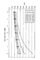
도 22D에는 증발기 압력 강하와 전력 생산과의 관계가 도시되어 있다.
도 23A 및 도 23B에는 본 발명에 따른 예시적인 OTEC 열 기관이 도시되어 있다.
다양한 도면에 걸쳐 동일한 도면 부호는 특별한 지시가 없는 한 동일한 구성 요소를 지시한다.1 shows an exemplary OTEC heat engine according to the prior art.
2 shows an exemplary OTEC power plant according to the prior art.
3 shows an OTEC structure according to the present invention.
3A shows an OTEC structure in accordance with the present invention.
Figure 4 shows an offset staved tube of the OTEC structure according to the present invention.
5 shows a detailed image of an offset stave pattern according to the present invention.
6 is a cross-sectional view of an offset stave type cold seawater tube according to the present invention.
7A to 7C show various staves according to the present invention, respectively.
8 shows a tongue and groove device of an individual stave of the present invention.
9 shows an active snap lock between two staves according to the invention.
10 shows an offset stave type cold seawater tube incorporating a reinforcement strike according to the invention.
Figure 11 shows the construction method of the cold seawater tube according to the present invention.
12 shows an example of a gimbaled pipe connection according to the prior art.
Figure 13 shows a cold sea water pipe connection according to the invention.
Figure 14 shows a cold seawater pipe connection according to the invention.
15 shows a cold seawater pipe connection method according to the present invention.
Figure 16 shows a cold seawater pipe connection to a flexible cold seawater pipe according to the present invention.
Figure 17 shows a cold seawater pipe connection according to the invention.
18 shows a cold seawater tube with a lifting collar according to the invention.
19 shows one aspect of the present invention in a cut away perspective view.
20 shows a heat exchanger deck according to the invention in plan view.
Figure 21 shows a cabinet heat exchanger according to the present invention.
22A shows a typical heat exchange cycle.
A cascaded multistage heat exchange cycle is shown in FIG. 22B.
22C shows a hybrid cascaded multi-stage heat exchange cycle.
Figure 22D shows the relationship between evaporator pressure drop and power generation.
23A and 23B show an exemplary OTEC heat engine in accordance with the present invention.
Like reference numerals designate like elements throughout the various drawings.
본 발명은 해양 온도차 발전(OTEC) 기술을 사용한 전력 생산에 관한 것이다. 본 발명의 태양은, 이전의 OTEC 발전소를 능가하는, 감소된 기생 부하, 증강된 안정성, 보다 적은 시공 및 작동 비용, 그리고 개선된 환경 이력과 함께 전체 효율이 개선된 부유식 OTEC 발전소에 관한 것이다. 다른 태양은 이러한 부유식 구조물과 일체형의 고체적의 해수 도관을 포함한다. 다단식 OTEC 열 기관의 모듈식 구성 및 구획화는 시공 및 유지 관리 비용을 감소시키며, 오프-그리드(off-grid) 작동을 제한하고, 작동 성능을 개선시키는 효과가 있다. 또 다른 태양은 열 교환 격실이 일체형으로 형성된 부유식 플랫폼을 제공하며, 파도의 작용으로 인한 플랫폼의 이동을 최소화한다. 일체형 구조의 부유식 플랫폼은 또한, 다단식 열 교환기를 통한 따뜻한 해수 또는 차가운 해수의 효율적인 유동을 제공함으로써, 효율을 증가시킬 뿐만 아니라 기생 전력 수요를 감소시킬 수도 있다. 본 발명의 태양은 적절한 깊이/온도 범위에서의 따뜻한 해수 및 차가운 해수 방출에 의해 중립적인 열 이력(thermal footprint)을 촉진한다. 전기의 형태로 추출되는 에너지는 해양의 체적 온도(bulk temperature)를 감소시킨다.TECHNICAL FIELD The present invention relates to power generation using off-shore thermo-generation (OTEC) technology. Aspects of the present invention are directed to floating OTEC power plants with improved overall efficiency with reduced parasitic loads, enhanced stability, less construction and operating costs, and improved environmental history over previous OTEC power plants. Other aspects include solid seawater conduits integrated with such floating structures. Modular construction and compartmentalization of multistage OTEC heat engines reduce construction and maintenance costs, limit off-grid operation, and improve operating performance. Another aspect provides a floating platform in which the heat exchange compartment is integrally formed, minimizing the movement of the platform due to the action of waves. The integrated platform, floating platform may also provide efficient flow of warm or cold seawater through a multi-stage heat exchanger, thereby increasing efficiency as well as reducing parasitic power demand. Aspects of the present invention promote a neutral thermal footprint by warm and cold seawater release at appropriate depth / temperature ranges. The energy extracted in the form of electricity reduces the bulk temperature of the ocean.
OTEC는 지구의 해양에 저장되는 태양으로부터의 열 에너지를 사용하여 전기를 생성하는 공정이다. OTEC는 온도가 상대적으로 더 높은 표층 해수와 온도가 상대적으로 더 낮은 심층 해수 사이의 온도차를 활용한다. 통상적으로, 이러한 온도차는 적어도 36℉(20℃)이다. 이러한 온도 조건은 대략 남회귀선과 북회귀선 사이의 또는 북위 20° 내지 남위 20° 사이의 열대 지역에서 나타난다. OTEC 공정은, 따뜻한 표층 해수가 열원으로서의 역할을 하며 차가운 심층 해수가 히트 싱크(heat sink)로서의 역할을 하는 방식으로, 온도차를 사용하여 랭킨 사이클(Rankine cycle) 발전을 실현하게 된다. 랭킨 사이클 터빈이 발전기를 구동시켜 전력이 생산된다.OTEC is a process that generates electricity using heat energy from the sun stored in the oceans of the earth. OTEC takes advantage of the temperature difference between surface waters with higher temperatures and deeper seawater with lower temperatures. Typically, this temperature difference is at least 36 ° F. (20 ° C.). These temperature conditions appear approximately in the tropics between the southern and northern tropics or between 20 ° and 20 ° north latitudes. The OTEC process realizes Rankine cycle generation using temperature differences in such a way that warm surface seawater acts as a heat source and cold deep seawater acts as a heat sink. Rankine cycle turbines drive the generator to generate power.
도 1에는, 따뜻한 해수 유입구(12), 증발기(14), 따뜻한 해수 유출구(15), 터빈(16), 차가운 해수 유입구(18), 응축기(20), 차가운 해수 유출구(21), 작동 유체 도관(22), 그리고 작동 유체 펌프(24)를 포함하는, 전형적인 OTEC 랭킨 사이클 열 기관(10)이 도시되어 있다.1,
작동 시에, 열 기관(10)은 다수의 작동 유체 중 어느 하나, 예를 들어, 암모니아와 같은 시판 냉매를 사용할 수 있다. 그외 다른 작동 유체로서, 프로필렌, 부탄, R-22 및 R-134a를 예로 들 수 있다. 그외 다른 시판 냉매가 사용될 수 있다. 대략 75℉ 내지 85℉ 이상의 따뜻한 해수가 따뜻한 해수 유입구(12)를 통해 해수면으로부터 또는 해수면 바로 아래로부터 뽑아 내어진 다음, 증발기(14)를 통과하는 암모니아 작동 유체의 온도를 상승시키도록 작용하게 된다. 암모니아는 대략 9.3atm의 증기 압력으로 증발하게 된다. 이렇게 얻어진 증기는 작동 유체 도관(22)을 따라 터빈(16)으로 운반된다. 암모니아 증기가 터빈(16)을 통과하면서 팽창됨에 따라, 발전기(25)를 구동시키기 위해 필요한 동력이 생산된다. 이후, 암모니아 증기는 응축기(20)로 들어가게 되며, 이곳에서 대략 3000ft 깊이의 해양 심층부로부터 뽑아 내어진 차가운 해수에 의해 액체 상태로 냉각된다. 응축기로 들어가는 차가운 해수의 온도는 대략 40℉이다. 응축기(20) 내부에서 온도가 대략 51℉인 암모니아 작동 유체의 증기 압력은 6.1atm이다. 따라서, 상당한 압력차가 터빈(16)을 구동시켜 전력을 생산하도록 이용 가능하다. 암모니아 작동 유체가 응축됨에 따라, 작동 유체 펌프(24)에 의해 액상의 작동 유체가 작동 유체 도관(22)을 통해 증발기(14) 내부로 다시 펌핑된다.In operation, the heat engine 10 may use any one of a number of working fluids, for example commercially available refrigerants such as ammonia. Other working fluids include propylene, butane, R-22 and R-134a. Other commercially available refrigerants may be used. Warm seawater of approximately 75 ° F. to 85 ° F. or greater is drawn from the sea level through the warm
도 1의 열 기관(10)은, OTEC가 상이한 작동 유체를 사용하며 보다 낮은 온도 및 압력에서 이루어진다는 차이점을 제외하고는, 기본적으로 대부분의 증기 터빈의 랭킨 사이클과 동일하다. 도 1의 열 기관(10)은 또한, 열원(예를 들어, 따뜻한 해수)과 저온 히트 싱크(예를 들어, 심층 해수)가 전력 생산을 위해 사용되도록 OTEC 사이클이 반대로 운영되는 점을 제외하고는, 시판되고 있는 냉매 장치와 유사하다. The heat engine 10 of FIG. 1 is basically the same as the Rankine cycle of most steam turbines, except that the OTEC uses different working fluids and is made at lower temperatures and pressures. The heat engine 10 of FIG. 1 also has the exception that the OTEC cycle is operated in reverse such that a heat source (eg warm seawater) and a low temperature heat sink (eg deep seawater) are used for power generation. It is similar to a commercially available refrigerant device.
도 2에는, 선박이나 플랫폼(210), 따뜻한 해수 유입구(212), 따뜻한 해수용 펌프(213), 증발기(214), 따뜻한 해수 유출구(215), 터빈-발전기(216), 차가운 해수용 관(217), 차가운 해수 유입구(218), 차가운 해수용 펌프(219), 응축기(220), 차가운 해수 유출구(221), 작동 유체 도관(22), 작동 유체 펌프(224), 그리고 관 연결부(230)를 포함하는, 전형적인 부유식 OTEC 설비(200)의 구성 요소가 도시되어 있다. OTEC 설비(200)는 또한, 발전, 변환 및 동력 전달용 시스템, 추진 장치, 반동 추진 엔진(thruster), 또는 계류(mooring) 시스템과 같은 위치 제어 시스템 뿐만 아니라 다양한 보조 시스템 및 지지 시스템(예를 들어, 숙박 시설, 비상 전원, 휴대용 급수 시설, 폐수 처리 시설, 소화 설비, 손상 조절 설비, 예비 부력 설비, 그리고 그외 다른 일반적인 선상 또는 해상 시스템)을 포함할 수 있다.2, a vessel or
도 1 및 도 2의 기본적인 열 기관 및 시스템을 사용하는 OTEC 발전소의 구현시 전체 효율은 3% 이하로 비교적 낮다. OTEC 발전소의 경우 열 효율이 낮기 때문에, OTEC 작동을 위해서는 발생 전력 1킬로와트당 상당 체적의 해수를 발전 시스템을 통과하여 유동시켜야만 한다. 이에 따라, 증발기 및 응축기에 열 교환 표면적이 큰 대형 열 교환기를 제공할 필요가 있다.The overall efficiency in the implementation of an OTEC power plant using the basic heat engine and system of FIGS. 1 and 2 is relatively low, less than 3%. Due to the low thermal efficiency of OTEC power plants, a significant volume of seawater per kilowatt of generated power must flow through the power generation system for OTEC operation. Accordingly, there is a need to provide large evaporators and condensers with large heat exchangers with large heat exchange surface areas.
이러한 상당 체적의 해수 및 넓은 열 교환 표면적은 따뜻한 해수용 펌프(213) 및 차가운 해수용 펌프(219)의 상당히 높은 펌핑 용량을 필요로 하여, 기지가 육상에 있는 시설에 대한 분배 용도로 또는 선상에서의 산업적 용도로 이용 가능한 순 전력을 감소시킨다. 또한, 대부분의 해상 선박의 경우 공간이 제한되어 있기 때문에, 이러한 상당 체적의 해수의 증발기나 응축기로의 이송 및 증발기나 응축기를 통한 유동을 촉진하기가 쉽지 않다. 실제로, 해수의 체적이 높을 경우 대구경 관 및 도관이 필요하다. 이러한 구조물을 제한된 공간에 설치하기 위해서는 기타 다른 기계 부품을 수용할 수 있도록 여러 번에 걸쳐 구조물을 구부리는 과정을 필요로 한다. 또한, 전형적인 해상 선박이나 구조물에서 나타나는 이러한 공간상 제약으로 인해 OTEC 발전소의 효율을 최대화하기 위해 필요한 넓은 열 교환 표면적을 달성하기가 쉽지 않다. 따라서, OTEC 시스템 및 선박이나 플랫폼은 전통적으로 크기가 크고 비싸다. 이러한 이유로, 보다 높은 온도 및 압력 조건을 사용하는 기타 다른 에너지 생산 사양과 비교하여, OTEC 작동이 고비용, 저수율 에너지 생산 사양을 나타낸다는 업계의 판단이 도출되어 왔다.This substantial volume of seawater and large heat exchange surface area requires the significantly higher pumping capacity of the
본 발명의 태양은 OTEC 작동 효율을 개선하며 시공 및 작동 비용을 줄이기 위한 기술적인 도전을 표명하는 것이다. Aspects of the present invention address technical challenges for improving OTEC operating efficiency and reducing construction and operating costs.
선박이나 플랫폼(210)은 차가운 해수용 관(217)과 선박이나 플랫폼(210) 사이의 동적인 힘을 최소화하며 플랫폼이나 선박 내부의 OTEC 장비에 관한 무해한 작동 환경을 제공할 수 있도록 이동이 적어야 한다. 이러한 선박이나 플랫폼(210)은 또한, 차가운 해수 및 따뜻한 해수 유입구(218, 212)를 통과하는 소정 체적의 흐름을 지지함으로써, 적절한 레벨의 OTEC 공정 효율을 보장하기에 충분한 양의 따뜻한 해수 및 차가운 해수가 도입될 수 있도록 구성되어야 한다. 선박이나 플랫폼(210)은 또한, 해양 표층으로의 열의 재순환을 방지하기 위하여, 선박이나 플랫폼(210)의 수선(waterline) 바로 아래의 차가운 해수 및 따뜻한 해수 유출구(221, 215)를 통한 차가운 해수 및 따뜻한 해수의 방출이 가능하도록 구성되어야 한다. 추가적으로, 선박이나 플랫폼(210)은 전력 생산 작동이 방해받는 일 없이 열악한 날씨에도 견딜 수 있어야 한다. The vessel or
OTEC 열 기관(10)은 효율 및 전력 생산을 최대화하기 위해 상당히 효율적인 열 사이클을 사용하여야 한다. 증발 및 응축 공정에서의 열 전달 뿐만 아니라 열 교환기의 재료 및 설계 구조에 따라 따뜻한 해수 일 파운드당 추출될 수 있는 에너지의 양이 제한된다. 증발기(214)와 응축기(220)에 사용되는 열 교환기는 기생 부하를 최소화하기 위한 낮은 수두 손실(head loss)과 함께 상당히 높은 따뜻한 해수 및 차가운 해수 유량을 필요로 한다. 열 교환기는 또한, 효율 증강을 위해 높은 열 전달 계수를 갖추어야 한다. 이러한 열 교환기는 효율 증강을 위해 따뜻한 해수 및 차가운 해수 유입구 온도에 맞춰질 수도 있는 재료 및 설계 구조로 구성될 수도 있다. 이러한 열 교환기 설계 구조는 비용 및 체적 감소를 위해 최소한도의 재료만을 사용하는 간단한 시공 방법을 사용하여 달성될 수 있어야 한다.The OTEC heat engine 10 must use a fairly efficient heat cycle to maximize efficiency and power production. In addition to heat transfer in the evaporation and condensation processes, the material and design of the heat exchanger limits the amount of energy that can be extracted per pound of warm seawater. Heat exchangers used in
터보 발전기(216)는 내부 손실을 최소화하는 한편 상당히 효율적이어야 하며, 효율 증강을 위해 특정 작동 유체용으로 맞춤형으로 형성될 수도 있다. The
도 3에는 이전의 OTEC 발전소의 효율을 증대시키며 직면한 많은 기술적인 도전들을 극복할 수 있는 본 발명의 일 실시 형태가 도시되어 있다. 이러한 실시 형태는 선박이나 플랫폼용 스파(spar)를 포함하며, 열 교환기 및 연관된 따뜻한 해수 및 차가운 해수 배관이 스파와 일체형으로 형성되어 있다.3 illustrates an embodiment of the present invention that can increase the efficiency of previous OTEC power plants and overcome many of the technical challenges encountered. This embodiment includes a spar for a vessel or platform, in which a heat exchanger and associated warm and cold seawater piping are integrally formed with the spar.
OTEC 스파(310)는 OTEC 발전소와 사용하기 위한 일체형 구성 요소인 다단식 열 교환 시스템을 수용한다. 스파(310)는 수선(305) 아래의 침수부(311)를 포함한다. 침수부(311)는 따뜻한 해수 흡입부(340), 증발부(344), 따뜻한 해수 배출부(346), 응축부(348), 차가운 해수 흡입부(350), 차가운 해수용 관(351), 차가운 해수 배출부(352), 그리고 기계 부품 데크부(354)를 포함한다. 데크 하우스(360)는 스파의 정상에 설치되어, 전기 조차장, 보조 및 비상 기계 부품 및 시스템, 보트 취급 장비, 그리고 사무실, 숙박 시설, 통신 센터 및 조종실과 같은 유인 공간을 수용한다. OTEC spar 310 houses a multi-stage heat exchange system that is an integral component for use with an OTEC power plant.
도 3A에는 따뜻한 해수 흡입부(340), 따뜻한 해수 펌프실(341), 적층형 증발부(344), 터빈 발전기(349), 적층형 응축부(348), 차가운 해수 흡입부(350), 그리고 차가운 해수용 펌프실(351)을 포함하는 본 발명에 따른 예시적인 기계 부품 레이아웃이 도시되어 있다. 3A shows a
작동 시에, 75℉ 내지 85℉의 따뜻한 해수가 따뜻한 해수 흡입부(340)를 통해 뽑아 내어진 다음, 도시하지 않은 일체형 구조의 따뜻한 해수용 도관을 통해 스파 하방으로 유동한다. OTEC 열 기관의 상당 체적의 해수 유동 요건으로 인해, 따뜻한 해수용 도관은 해수를 500,000gpm 내지 6,000,000gpm의 유량으로 증발부(344)로 보내도록 구성된다. 이러한 따뜻한 해수용 도관의 직경은 6ft 내지 35ft 이상의 범위이다. 이러한 크기로 형성됨에 따라, 따뜻한 해수용 도관은 스파(310)의 수직 구조 부재를 형성하게 된다. 따뜻한 해수용 도관은 스파(310)를 수직 방향으로 지지하기에 충분한 강도를 갖춘 대구경 관의 형태로 형성될 수 있다. 대안으로서, 따뜻한 해수용 도관이 스파(310)와 일체형으로 구성되는 통로일 수도 있다. In operation, warm seawater of 75 ° F. to 85 ° F. is drawn through the
이후, 따뜻한 해수는 작동 유체가 증기 상태로 가열하기 위해 하나 이상의 적층형 다단식 열 교환기가 수용되어 있는 증발기(344)를 통과하여 유동한다. 따뜻한 해수는 이어서, 따뜻한 해수 배출부(346)를 통해 스파(310)로부터 배출된다. 따뜻한 해수 배출부는, 환경적 충격을 최소화할 수 있도록 배출되는 따뜻한 해수의 온도와 대략 동일한 온도의 열을 내재한 해수 층의 깊이에, 또는 이러한 해수 층에 가까운 깊이에 위치할 수도 있으며, 또는 따뜻한 해수용 배출관을 통해 이러한 깊이로 보내질 수 있다. 따뜻한 해수 배출부는 따뜻한 해수 흡입부 또는 차가운 해수 흡입부와의 열의 재순환이 발생하지 않도록 하기에 충분한 깊이에 마련될 수 있다. The warm seawater then flows through an
온도가 대략 40℉인 차가운 해수가 차가운 해수용 관(351)을 통해 2500ft 내지 4200ft 이상의 범위의 깊이에서 뽑아 내어진다. 이렇게 해서 얻어진 차가운 해수는 차가운 해수 흡입부(350)를 통해 스파(310)로 유입된다. OTEC 열 기관의 상당 체적의 해수 유동 요건으로 인해, 차가운 해수 도관은 해수를 500,000gpm 내지 3,500,000gpm의 범위의 유량으로 응축부(348)로 보내도록 구성된다. 이러한 차가운 해수 도관의 직경은 6ft 내지 35ft 이상의 범위이다. 이러한 크기로 형성됨에 따라, 차가운 해수 도관은 스파(310)의 수직 구조 부재를 형성하게 된다. 차가운 해수 도관은 스파(310)를 수직 방향으로 지지하기에 충분한 강도를 갖춘 대구경 관의 형태로 형성될 수 있다. 대안으로서, 차가운 해수 도관이 스파(310)와 일체형으로 구성되는 통로일 수도 있다. Cold seawater with a temperature of approximately 40 ° F. is drawn through a
이후, 차가운 해수는 적층형의 다단식 응축부(348)로 상방으로 유동하여, 이곳에서 작동 유체를 액체 상태로 냉각시키도록 사용된다. 차가운 해수는 이어서, 차가운 해수 배출부(352)를 통해 스파(310)로부터 배출된다. 차가운 해수의 배출는, 배출되는 차가운 해수의 온도와 대략 동일한 온도의 열을 내재한 해수 층의 깊이에, 또는 이러한 해수 층에 가까운 깊이에 위치할 수도 있으며, 또는 차가운 해수용 배출관을 통해 이러한 깊이까지 보내질 수 있다. 차가운 해수 배출는 따뜻한 해수 흡입부 또는 차가운 해수 흡입부와의 열의 재순환이 발생하지 않도록 하기에 충분한 깊이로 보내질 수 있다. The cold sea water then flows upwards to the stacked
기계 부품 데크부(354)가 증발부(344)와 응축부(348)의 사이에 수직 방향으로 배치될 수 있다. 증발부(344)의 아래에 기계 부품 데크부(354)를 배치함으로써 거의 직선 경로로 따뜻한 해수가 흡입부로부터 다단식 증발기를 통과하여 배출부로 유동할 수 있다. 또한, 응축부(348)의 위에 기계 부품 데크부(354)를 배치함으로써, 거의 직선 경로로 차가운 해수가 흡입부로부터 다단식 응축기를 통과하여 배출부로 유동할 수 있다. 기계 부품 데크부(354)는 터보 발전기(356)를 포함한다. 작동 시에, 증발부(344)로부터 나온, 증기 상태로 가열된 고온 작동 유체가 하나 이상의 터보 발전기(356)로 유동하게 된다. 작동 유체가 터보 발전기(356)에서 팽창됨에 따라, 전력 생산을 위한 터빈의 구동이 이루어진다. 작동 유체는 이후, 응축부(348)로 유동하여, 이곳에서 액체 상태로 냉각된 다음 증발부(344)로 펌핑된다.The
열 교환기의 성능은 유체 사이의 유효 온도차 뿐만 아니라 열 교환기 표면에서의 열 전달 계수에 의해 영향을 받는다. 열 전달 계수는 일반적으로, 열 전달 표면을 가로지르는 유체의 유속에 따라 변한다. 유속이 높을수록 높은 펌핑력을 필요로 하여, 발전소의 순 효율이 감소하게 된다. 하이브리드 캐스케이드형 다단식 열 교환 시스템(hybrid cascading multi-stage heat exchange system)은 유속 감소 및 발전소 효율 상승을 촉진한다. 적층형 하이브리드 캐스케이드 열 교환 설계 구조는 또한, 열 교환기를 통한 압력 강하 감소를 촉진한다. 또한, 수직형 발전소의 설계 구조는 전체 시스템에 걸친 압력 강하 감소를 촉진한다. 하이브리드 캐스케이드 다단식 열 교환 시스템은, 전체 내용이 본 명세서에 참조로써 인용되고 있는, 2010년 1월 21일자로 출원된, "해양 온도차 발전소(Ocean Thermal Energy Conversion Plant)"를 제목으로 하는 미국 특허 출원 제 12/691,663 호(대리인 문서 번호 제 25667-0004001 호)에 설명되어 있다.The performance of the heat exchanger is influenced by the heat transfer coefficient at the surface of the heat exchanger as well as the effective temperature difference between the fluids. The heat transfer coefficient generally varies with the flow rate of the fluid across the heat transfer surface. Higher flow rates require higher pumping power, which reduces the net efficiency of the power plant. Hybrid cascading multi-stage heat exchange systems promote reduced flow rates and increased plant efficiency. The stacked hybrid cascade heat exchange design structure also promotes reduced pressure drop through the heat exchanger. In addition, the design structure of the vertical power plant promotes a reduction in pressure drop across the entire system. The hybrid cascade multistage heat exchange system is described in US patent application entitled "Ocean Thermal Energy Conversion Plant," filed Jan. 21, 2010, the entire contents of which are incorporated herein by reference. 12 / 691,663 (Attorney Docket No. 25667-0004001).
차가운 해수용 관Cold sea water pipe
전술한 바와 같이, OTEC 작동은 일정한 온도의 차가운 해수 공급원을 필요로 한다. 냉각수의 온도 변화는 OTEC 발전소의 전체 효율에 상당한 영향을 미칠 수 있다. 이에 따라, 2700ft 내지 4200ft 이상의 범위의 깊이로부터 대략 40℉의 온도의 해수가 뽑아 내어진다. 이렇게 뽑아 내어진 해수를 OTEC 발전소에 사용되는 해수면으로 보내기 위해서는 길이가 긴 흡입관이 필요하다. 적당한 성능 및 내구성을 갖춘 관의 시공 비용으로 인해 이러한 차가운 해수용 관은 상업적으로 성공 가능한 OTEC 작동에 방해가 되어 왔다.As mentioned above, OTEC operation requires a constant source of cold seawater. The change in temperature of the coolant can have a significant impact on the overall efficiency of the OTEC power plant. Thus, seawater at a temperature of approximately 40 ° F. is extracted from a depth in the range of 2700 ft to 4200 ft or more. A long suction line is needed to send this extracted seawater to the sea level used in the OTEC power plant. Due to the cost of constructing adequately performance and durable pipes, these cold sea water pipes have hampered commercially viable OTEC operation.
적당한 성능 및 내구성을 갖춘 관의 시공 비용으로 인해 이러한 차가운 해수용 관은 상업적으로 성공 가능한 OTEC 작동에 방해가 되어 왔다. OTEC는, 전력 생산에 있어서의 최대 효율을 보장하기 위해서는, 소망하는 온도의 상당 체적의 해수를 필요로 한다. OTEC 작동용으로 특화된 이전의 차가운 해수용 관 설계 구조에는 구획화된 구성이 포함되어 왔다. 충분한 길이가 달성될 때까지 원통형 관 섹션이 함께 직렬로 볼트 체결되거나 기계적으로 연결되어 왔다. 관 섹션의 조립은 발전소 설비 부근에서 수행되어 왔으며, 이후 시공 완료된 관은 위 아래가 뒤집힌 상태로 설치되었다. 이러한 접근법은 그러나, 관 섹션 사이의 연결 지점에서의 응력 및 피로를 포함하는 상당한 결함을 드러내었다. 또한, 연결부 장비가 전체 관 중량에 추가됨으로써, 관 섹션 연결부 및 완전히 조립된 CWP와 OTEC 플랫폼이나 선박 사이의 연결부에 있어서 응력 및 피로 문제와 관련하여 보다 복잡한 사항들을 고려하여야만 한다.Due to the cost of constructing adequately performance and durable pipes, these cold sea water pipes have hampered commercially viable OTEC operation. OTEC requires a significant volume of seawater at a desired temperature to ensure maximum efficiency in power generation. Previous cold seawater tube design structures specialized for OTEC operation have included compartmentalized configurations. The cylindrical tube sections have been bolted in series or mechanically connected together until a sufficient length has been achieved. Assembly of the pipe sections has been carried out in the vicinity of the power plant equipment, after which the finished pipes have been installed upside down. This approach, however, has revealed significant deficiencies, including stress and fatigue at the point of connection between the tube sections. In addition, as connection equipment is added to the overall tube weight, more complex considerations regarding stress and fatigue issues have to be taken into account for the pipe section connections and the connection between the fully assembled CWP and the OTEC platform or ship.
차가운 해수용 관("CWP(Cold Water Pipe)")은 2700ft 내지 4200ft 이상의 사이의 범위의 해양 심층부에 마련된 차가운 해수 저장조로부터 해수를 뽑아내도록 사용된다. 차가운 해수는 발전소 터빈으로부터 방출되는 증기 상태의 작동 유체를 액체 상태로 냉각 및 응축시키도록 사용된다. CWP와 선박이나 플랫폼과 CWP 사이의 연결부는 관 중량에 의해 부과되는 정적 부하 및 동적 부하와, 100년 호우 심도에 이르는 파도 및 수류 부하가 걸리는 경우의 관과 플랫폼의 상대 운동, 그리고 해수 펌프 흡입에 의해 야기되는 붕괴 하중을 견딜 수 있도록 구성된다. CWP는 낮은 항력 손실로 필요한 해수 유동을 처리할 수 있는 크기로 형성되며, 해수에서의 부식 저항 및 내구성을 갖춘 재료로 구성된다.Cold seawater pipes ("CWPs") are used to extract seawater from cold seawater reservoirs located in deep ocean areas in the range between 2700 ft and 4200 ft or more. Cold seawater is used to cool and condense the vapor working fluid from the power plant turbine to the liquid state. The connection between the CWP and the vessel or platform and the CWP is based on the static and dynamic loads imposed by the tube weight, the relative movement of the pipe and platform in the event of a wave and water load up to a 100-year heavy rain depth, and the suction of the seawater pump. It is configured to withstand the collapse load caused by it. The CWP is sized to handle the required seawater flow with low drag losses and consists of materials that are corrosion resistant and durable in seawater.
차가운 해수용 관의 길이는 해수의 온도가 대략 40℉인 깊이로부터 해수를 뽑아 내야하는 필요에 따라 정해진다. CWP의 길이는 2000ft 내지 4000ft 이상 사이의 범위일 수 있다. 본 발명의 태양에 있어서, 차가운 해수용 관의 길이는 대략 3000ft일 수 있다.The length of the cold seawater tube is determined by the need to extract the seawater from a depth of approximately 40 ° F. The length of the CWP may range between 2000 ft and 4000 ft or more. In an aspect of the present invention, the length of the cold seawater tube may be approximately 3000 feet.
CWP의 직경은 발전소 크기 및 해수 유동 요건에 의해 결정된다. 관을 통과하는 해수의 유량은 소망하는 출력 및 OTEC 발전소 효율에 의해 결정된다. CWP는 500,000gpm 내지 3,500,000gpm 이상 사이의 범위의 유량으로 선박이나 플랫폼의 차가운 해수용 도관으로 차가운 해수를 운반할 수 있다. 차가운 해수용 관의 직경은 6ft 내지 35ft 이상 사이의 범위일 수 있다. 본 발명의 태양에 있어서, CWP의 직경은 대략 31ft이다.The diameter of the CWP is determined by plant size and seawater flow requirements. The flow rate of seawater through the pipe is determined by the desired power and the OTEC power plant efficiency. The CWP can deliver cold seawater to cold seawater conduits on ships or platforms at flow rates ranging from 500,000 gpm to over 3,500,000 gpm. The diameter of the cold seawater tube may range between 6 ft and 35 ft or more. In an aspect of the invention, the diameter of the CWP is approximately 31 feet.
OTEC 작동용으로 특화된 이전의 차가운 해수용 관의 설계 구조에는 구획화된 구성이 포함되어 왔다. 충분한 길이가 달성될 때까지 10ft 내지 80ft 범위의 길이의 원통형 관 섹션이 함께 직렬로 볼트 체결되거나 기계적으로 연결되어 왔다. 다수의 원통형 관 섹션을 사용함으로써, CWP의 조립은 발전소 설비 부근에서 수행되어 왔으며, 이후 시공 완료된 관은 위 아래가 뒤집힌 상태로 설치되었다. 이러한 접근법은 그러나, 관 섹션 사이의 연결 지점에서의 응력 및 피로를 포함하는 상당한 결함을 드러내었다. 또한, 연결부 장비가 전체 관 중량에 추가됨으로써, 관 섹션 연결부 및 완전히 조립된 CWP와 OTEC 플랫폼이나 선박 사이의 연결부에 있어서 응력 및 피로와 관련하여 보다 복잡한 사항들을 고려하여야만 한다.The design structure of previous cold seawater pipes specialized for OTEC operation has included compartmentalized configurations. Cylindrical tube sections in the range of 10 to 80 ft long have been bolted or mechanically connected together in series until sufficient length has been achieved. By using a number of cylindrical tube sections, the assembly of the CWP has been performed near the power plant equipment, after which the finished tube was installed upside down. This approach, however, has revealed significant deficiencies, including stress and fatigue at the point of connection between the tube sections. In addition, as connection equipment is added to the overall tube weight, more complex issues regarding stress and fatigue have to be taken into account for the pipe section connections and the connection between the fully assembled CWP and the OTEC platform or ship.
도 4를 참조하면, 연속적인 오프셋 스테이브형의 차가운 해수용 관이 도시되어 있다. 차가운 해수용 관(451)은, 오프셋 스테이브 구성을 사용하는 대신, 이전의 CWP 설계 구조에서와 같은 구획 연결부를 포함하지 않는다. CWP(451)는 부유식 OTEC 플랫폼(411)의 침수부와의 연결을 위한 상단 부분(452)을 포함한다. 상단부(452)의 반대쪽은 하단 부분(454)으로서, 밸러스트(ballast) 시스템, 정착 시스템, 및/또는 흡입 스크린을 포함할 수 있다.4, there is shown a cold seawater tube of continuous offset stave type. The
CWP(451)는 실린더를 형성하도록 구성되는 복수 개의 오프셋 스테이브(offset stave)를 포함한다. 일 태양에 있어서, 복수 개의 오프셋 스테이브는 다수의 제 1 스테이브(465)와 다수의 제 2 스테이브(467)가 번갈아 형성되어 구성될 수 있다. 각각의 제 1 스테이브는 상측 가장자리(471)와 하측 가장자리(472)를 포함한다. 각각의 제 2 스테이브는 상측 가장자리(473)와 하측 가장자리(474)를 포함한다. 일 태양에 있어서, (제 2 스테이브 부분(467)의) 상측 가장자리(473)가 (제 1 스테이브 부분(465)의) 상측 가장자리(471)로부터 수직 방향으로 3% 내지 97% 범위의 변위로 이격되도록 제 2 스테이브(467)는 인접한 제 1 스테이브 부분(465)으로부터 수직 방향으로 오프셋 배치된다. 다른 태양에 있어서, 인접한 스테이브 사이의 오프셋 거리는 대략 5%, 10%, 15%, 20%, 25%, 30%, 35%, 40%, 45%, 50% 또는 그 이상일 수 있다.
도 5는 본 발명의 일 태양에 따른 오프셋 스테이브 패턴의 세부도이다. 이 패턴은 각기 상측 가장자리 부분(471), 하측 가장자리 부분(472), 연결 가장자리(480), 그리고 오프셋 가장자리(478)를 구비하는 다수의 제 1 스테이브(465)를 포함한다. 이러한 패턴은 또한, 각기 상측 가장자리 부분(473), 하측 가장자리 부분(474), 연결 가장자리(480), 그리고 오프셋 가장자리(479)를 구비하는 다수의 제 2 스테이브(467)를 포함한다. 차가운 해수용 관의 형성 시에, 연결 가장자리(480)의 길이는, 상측 가장자리(471)로부터 하측 가장자리(472)까지 측정한 경우, 제 1 스테이브 섹션(465)의 길이의 대략 3% 내지 97%가 되도록 제 1 스테이브 섹션(465)이 제 2 스테이브 섹션(467)에 연결된다. 일 태양에 있어서, 연결 가장자리(480)는 스테이브의 길이의 대략 50%, 55%, 60%, 65%, 70%, 75%, 80%, 85% 또는 90%이다.5 is a detail view of an offset stave pattern, in accordance with an aspect of the present invention. The pattern includes a plurality of
완전히 시공된 관의 경우, 제 1 스테이브(465)가 연결 가장자리(480)를 따라 제 2 스테이브(467)에 연결될 수 있음을 알 수 있을 것이다. 제 1 스테이브(465)는 또한, 추가의 제 1 스테이브 부분, 추가의 제 2 스테이브 부분, 또는 그외 다른 스테이브 부분을 포함하는 추가 스테이브에 오프셋 가장자리(478)를 따라 연결될 수 있다. 유사하게, 제 2 스테이브(467)는 연결 가장자리(480)를 따라 제 1 스테이브 부분에 연결될 수 있음을 알 수 있을 것이다. 제 2 스테이브(467)는 또한, 추가의 제 1 스테이브 부분, 추가의 제 2 스테이브 부분, 또는 그외 다른 스테이브 부분을 포함하는 추가 스테이브에 오프셋 가장자리(479)를 따라 연결될 수 있다.It will be appreciated that for a fully constructed tube, the first stave 465 can be connected to the second stave 467 along the connecting
태양에 따라, 다수의 제 1 스테이브(465)와 다수의 제 2 스테이브(467) 사이의 연결 가장자리(480)는 관의 원주면을 중심으로 각각의 스테이브에 대한 스테이브 길이의 일정 백분율 또는 일정 길이로 형성될 수 있다. 다수의 제 1 스테이브(465)와 다수의 제 2 스테이브(467) 사이의 연결 가장자리(480)는 차가운 해수 관(451)의 종 방향 축선을 따라 각각의 스테이브에 대한 스테이브 길이의 일정 백분율 또는 일정 길이로 형성될 수 있다. 또 다른 태양에 있어서, 연결 가장자리(480)는 번갈아 배치된 제 1 스테이브(465)와 제 2 스테이브(467)의 사이에서 길이가 변할 수 있다.According to an aspect, the connecting
도 5에 도시된 바와 같이, 제 1 스테이브(465)와 제 2 스테이브(467)는 동일한 치수를 갖는다. 태양에 따라, 제 1 스테이브(465)는 30inch 내지 130inch 이상의 범위의 폭과, 30ft 내지 60ft의 범위의 길이, 그리고 1inch 내지 24inch의 범위의 두께로 형성될 수 있다. 일 태양에 있어서, 스테이브의 치수는 폭이 대략 80inch이며, 길이가 40ft이고, 두께가 4inch 내지 12inch 일 수 있다. 대안으로서, 제 1 스테이브(465)의 폭 또는 길이가 제 2 스테이브(467)의 폭 또는 길이와 상이할 수 있다.As shown in FIG. 5, the first stave 465 and the second stave 467 have the same dimensions. According to an aspect, the first stave 465 can be formed in a width in the range of 30 inches to 130 inches or more, a length in the range of 30 feet to 60 feet, and a thickness in the range of 1 inch to 24 inches. In one aspect, the dimensions of the stave may be approximately 80 inches wide, 40 feet long, and 4 inches to 12 inches thick. Alternatively, the width or length of the first stave 465 may be different from the width or length of the second stave 467.
도 6은 번갈아 배치된 제 1 스테이브(465)와 제 2 스테이브(467)를 보여주는, 차가운 해수용 관(451)의 단면도이다. 각각의 스테이브는 내면(485)과 외면(486)을 포함한다. 인접한 스테이브가 연결 표면(480)을 따라 연결되어 있다. 단일 스테이브의 양 측면 상의 두 개의 연결 표면은 각도(α)를 이룬다. 각도(α)는 360°를 스테이브의 총 개수로 나눈 값으로 결정된다. 일 태양에 있어서, 각도(α)는 1° 내지 36°의 범위일 수 있다. 일 태양에 있어서, 각도(α)는 16개의 스테이브로 이루어진 관의 경우 22.5°일 수 있으며, 또는 32개의 스테이브로 이루어진 관의 경우 11.25°일 수 있다.FIG. 6 is a cross-sectional view of a
차가운 해수용 관(451)의 개개의 스테이브는 폴리 염화 비닐(PVC), 폴리 염화 비닐 염화물(CPVC), 섬유 강화 플라스틱(FRP), 강화 폴리머 모르타르(RPMP), 폴리프로필렌(PP), 폴리에틸렌(PE), 가교 결합 고밀도 폴리에틸렌(PEX), 폴리부틸렌(PB), 아크릴로니트릴 부타디엔 스티렌(ABS), 폴리우레탄, 폴리에스테르, 섬유 강화 폴리에스테르, 나일론 강화 폴리에스테르, 비닐 에스테르, 섬유 강화 비닐 에스테르, 나일론 강화 비닐 에스테르, 콘크리트, 세라믹, 또는 이들 중 하나 이상의 합성물로 형성될 수 있다. 개개의 스테이브는 표준 제조 기술을 사용하여 성형, 압출, 또는 인발 성형될 수 있다. 일 태양에 있어서, 개개의 스테이브는 소망하는 형상 및 형태로 인발 성형되며, 섬유 또는 나일론 강화 비닐 에스테르를 포함한다. 비닐 에스테르는 켄터키주 코빙톤(Kentucky, Covington) 소재 아쉬랜드 케미컬(Ashland Chemical)사에 의해 시판되고 있다.The individual staves of the
일 태양에 있어서, 스테이브는 적당한 접착제를 사용하여 인접한 스테이브에 접합된다. 가요성 이음부 및 균일한 관 성능을 제공하도록 가요성 수지가 사용될 수 있다. 본 발명의 태양에 있어서, 강화 비닐 에스테르를 포함하는 스테이브는 비닐 에스테르 수지를 사용하여 인접한 스테이브에 접합된다. 메사츠세츠주 댄버(Massachusetts, Danver) 소재 플레식스 스트럭쳐럴 어드히시브(Plexis Structural Adhesive)사에 의해 제조되고 있는 상품명 MA560-1과 같은 메타크릴레이트 접착제가 또한 사용될 수 있다.In one aspect, the stave is bonded to adjacent staves using a suitable adhesive. Flexible resins can be used to provide flexible joints and uniform tube performance. In an aspect of the invention, a stave comprising reinforced vinyl esters is bonded to adjacent staves using a vinyl ester resin. Methacrylate adhesives such as trade name MA560-1, manufactured by Plexis Structural Adhesive, Danver, Massachusetts, may also be used.
도 7A 내지 도 7C를 참조하면, 개별 스테이브(465)가 상측 가장자리(471), 하측 가장자리(472), 그리고 하나 이상의 공극(475)을 포함하는 다양한 스테이브 구성이 도시되어 있다. 공극(475)은 중공형으로, 물이 채워질 수 있으며, 수지가 채워질 수 있으며, 접착제가 채워질 수 있고, 또는 유리 기포 강화 플라스틱(syntactic foam)과 같은 발포 재료가 채워질 수 있다. 유리 기포 강화 플라스틱은 수지와 크기가 작은 유리 비드(bead)로 이루어진 매트릭스(matrix) 형태의 물질이다. 비드는 중공형 또는 중실형일 수 있다. 공극(475)의 충전 상태가 스테이브 및/또는 차가운 해수용 관(451)의 부력에 영향을 미칠 수 있다. 도 7A에는 단일 공극(475)이 도시되어 있다. 일 태양에 있어서, 도 7B에 도시된 바와 같이, 다수의 공극(475)이 스테이브의 길이를 따라 균일한 간격으로 배치될 수 있다. 일 태양에 있어서, 도 7C에 도시된 바와 같이, 하나 이상의 공극(475)이 스테이브의 일 단부측으로, 예를 들어, 하측 가장자리(472) 측으로 배치될 수 있다.Referring to FIGS. 7A-7C, various stave configurations are shown in which individual staves 465 include an
도 8을 참조하면, 각각의 개별 스테이브(465)는 상측 가장자리(471), 하측 가장자리(472), 제 1 종방향 측면(491), 그리고 제 2 종방향 측면(492)을 포함할 수 있다. 일 태양에 있어서, 종방향 측면(491)은 텅(tongue)(493)과 같은 연결 부재를 포함한다. 연결 부재는, 선택적으로, 비스킷(biscuit), 반턱 이음부(half-lap joint), 또는 그외 다른 연결 구조를 포함할 수 있다. 제 2 종방향 측면(492)은 홈(494)과 같은 짝을 이루는 연결 표면을 포함한다. 사용 시에, 제 1 스테이브의 제 1 종방향 측면(491)이 제 2 스테이브의 제 2 종방향 측면(492)과 짝을 이루거나 연결된다. 도시하지는 않았지만, 텅 앤드 그루브(tongue and groove)와 같은 연결 구조 또는 그외 다른 구조가, 일 스테이브를 종방향으로 인접한 스테이브에 연결하기 위해, 상측 가장자리(471)와 하측 가장자리(472)에 사용될 수 있다.Referring to FIG. 8, each individual stave 465 may include an
본 발명의 태양에 있어서, 제 1 종방향 측면은 제 2 종방향 측면(492)과 짝을 이루어 정합하기 위한 능동형 스냅 잠금식(positive snap lock) 연결부(491)를 포함할 수 있다. 능동형 스냅 잠금식 연결부 또는 스냅 잠금식 연결부는 전체 내용이 본 명세서에 참조로써 인용되고 있는 미국 특허 제 7,131,242 호에 개괄적으로 설명되어 있다. 능동형 스냅 잠금부는 텅(493)의 전체 길이에 걸쳐 마련될 수도 있으며, 또는 텅(493)의 일부분에만 마련될 수도 있다. 이러한 텅(493)은 스냅 리벳(snap rivet)을 포함할 수 있다. 텅(493)이 스냅 잠금 구조를 포함하는 경우, 홈(494)을 포함하는 제 2 종방향 측면 상에 적절한 수용 구조가 마련됨을 알 수 있을 것이다.In an aspect of the invention, the first longitudinal side may include a positive
도 9에는 수형(male) 부분(970)이 칼라(collar)(972)를 포함하는 예시적인 능동형 스냅 잠금 시스템이 도시되어 있다. 수형 부분(970)은 오목한 칼라 장착부(977)를 포함하는 수용부(975)와 기계적으로 정합된다. 사용 시에, 칼라 부분(972)이 오목한 칼라 장착부(977)와 정합하도록 수형 부분(970)이 수용부(975) 내로 삽입된다. 이 경우, 수형 부분(970)의 삽입은 허용되지만, 수형 부분의 해제 또는 회수는 방지된다.9 illustrates an exemplary active snap lock system in which the
두 개의 스테이브형 부분을 함께 기계적으로 잠금 결합하도록 오프셋 스테이브식 관의 스테이브형 부분 사이에 능동형 스냅 잠금 이음부가 사용될 수 있다. 능동형 스냅 잠금 이음부는 수지 또는 접착제와 조합하여 또는 단독으로 사용될 수 있다. 일 태양에 있어서, 능동형 스냅 잠금 이음부와 조합하여 가요성의 수지가 사용된다.An active snap lock joint can be used between the stave portions of the offset stave tube to mechanically lock the two stave portions together. The active snap lock joints can be used alone or in combination with a resin or adhesive. In one aspect, flexible resins are used in combination with active snap lock joints.
도 10에는 번갈아 배치되는 제 1 스테이브(465)와 제 2 스테이브(467)를 포함하며, 차가운 해수용 관(451)의 외면의 적어도 일부를 덮고 있는 나선형으로 권선된 리본(497)을 추가로 포함하는 오프셋 스테이브 구성을 갖는 차가운 해수용 관(451)이 도시되어 있다. 태양에 따라, 상기 리본이 차가운 해수용 관(451)의 하측부(454)로부터 차가운 해수용 관(451)의 상측부(452)로 연속적으로 형성된다. 다른 태양에 있어서, 리본(497)은 해수가 차가운 해수용 관(451)을 지나쳐 이동함으로 인해 와류 발산을 경험하게 되는 관(451)의 부분에만 제공된다. 이러한 리본(497)은 차가운 해수용 관(451)을 반경 방향 및 종방향으로 지지하는 역할을 한다. 리본(497)은 또한, 차가운 해수용 관을 따라 진동이 발생하는 것을 방지하며 해류 작용으로 인한 와류 발산을 감소시키는 역할을 한다.FIG. 10 further includes a
리본(497)은 차가운 해수용 관(451)의 개별 스테이브와 동일한 두께 및 폭으로 형성될 수 있으며, 또는 개별 스테이브의 폭의 2배, 3배, 4배 이상의 두께 및 10배에 이르는(예를 들어, 2배, 3배, 4배, 5배, 6배, 7배, 8배, 9배 또는 10배) 폭으로 형성될 수 있다.The
리본(497)은 차가운 해수용 관의 외면 상에, 이 외면을 따라 실질적으로 평평한 상태로 놓여 지도록 장착될 수 있다. 일 실시예에 있어서, 리본(497)은 차가운 해수용 관(451)의 외면으로부터 외측으로 돌출되어 나선형으로 권선된 스트레이크(strake)를 형성할 수 있다. 본 발명의 태양에 있어서, 리본 또는 스트레이크(497)의 다양한 부분에 핀(fin), 블레이드(blade) 또는 포일(foil)이 부착될 수 있다. 이러한 핀은 차가운 해수용 관의 일부의 둘레에 나선형으로 권선되거나 차가운 해수용 관의 전체 길이에 걸쳐 나선형으로 권선되는 형태로 형성될 수 있다. 핀은, 차가운 해수용 관에 의해 야기되는 와류 조건을 방지하기 위하여, 소정 개수로 스트레이크를 중심으로 각도를 이루며 마련될 수 있다. 몇몇 태양에 있어서, 핀은 관 표면으로부터 관 직경의 1/32 내지 1/3의 범위(예를 들어, 관 직경의 대략 1/32, 관 직경의 대략 1/16, 관 직경의 대략 1/8, 관 직경의 대략 1/7, 관 직경의 대략 1/6, 관 직경의 대략 1/5, 관 직경의 대략 1/4, 그리고 관 직경의 대략 1/3)의 거리로 돌출될 수 있다. The
리본(497)은, 폴리 염화 비닐(PVC), 폴리 염화 비닐 염화물(CPVC), 섬유 강화 플라스틱(FRP), 강화 폴리머 모르타르(RPMP), 폴리프로필렌(PP), 폴리에틸렌(PE), 가교 결합 고밀도 폴리에틸렌(PEX), 폴리부틸렌(PB), 아크릴로니트릴 부타디엔 스티렌(ABS), 폴리우레탄, 폴리에스테르, 섬유 강화 폴리에스테르, 비닐 에스테르, 강화 비닐 에스테르, 콘크리트, 세라믹, 또는 이들 중 하나 이상의 합성물을 포함하는, 차가운 해수 관(451)을 형성하는 다수의 스테이브의 재료와 호환 가능한 어느 적당한 재료로 형성될 수 있다. 리본(497)은 표준 제조 기술을 사용하여 성형, 압출, 또는 인발 성형될 수 있다. 일 태양에 있어서, 리본(497)은 소망하는 형상 및 형태로 인발 성형되며, 차가운 해수용 관(451)의 스테이브에 사용되는 바와 유사한 섬유 또는 나일론 강화 비닐 에스테르를 포함한다. 리본(497)은 적당한 접착제 또는 전술한 재료 중 어느 하나의 수지를 포함하는 수지를 사용하여 차가운 해수용 관(451)에 연결될 수 있다.
몇몇 태양에 있어서, 리본(497)은 차가운 해수용 관(451)의 길이를 따라 비연속적으로 형성된다. 몇몇 태양에 있어서, 리본(497)은 차가운 해수용 관(451)의 원주면을 중심으로 비연속적으로 형성된다. 몇몇 태양에 있어서, 리본(497)은 차가운 해수용 관(451)의 외면에 고착되는 수직 방향 스트립(strip)을 포함한다. 몇몇 태양에 있어서, 반경 방향 또는 그외 다른 방향으로의 구조적 지지가 필요한 경우, 리본(497)이 차가운 해수 관의 외면의 둘레에 마련되는 원주 방향 지지 부재의 역할을 수행할 수 있다.In some aspects,
리본(497)은 적당한 가요성 접착제를 사용하여 차가운 해수용 관의 외면에 접착제를 이용하여 접합되거나 고착될 수 있다. 일 태양에 있어서, 리본(497)은 다수의 능동형 스냅 잠금부를 사용하여 차가운 해수용 관(451)의 외면에 기계적으로 결합될 수 있다.The
도 11을 참조하면, 차가운 해수용 관의 조립을 위한 예시적인 방법을 통해 차가운 해수용 관(451)의 효율적인 이송 및 조립이 이루어진다. 전술한 바와 같은 소망하는 오프셋 간격을 갖도록 제 1 및 제 2 스테이브 부분을 번갈아 정렬하는 단계(1110)에 의해 수직 방향의 원통형 관 섹션이 조립된다. 이후, 제 1 및 제 2 스테이브 부분을 연결하는 단계(1120)에 의해 원통형 관 섹션이 형성된다. 오프셋 배치되는 제 1 및 제 2 스테이브는 각종 연결 방법 중 어느 하나를 사용하여 연결될 수 있다. 일 태양에 있어서, 다수의 오프셋 배치되는 제 1 및 제 2 스테이브 부분이 텅 앤드 그루브 장치 및 가요성 접착제를 사용하여 연결된다. 일 태양에 있어서, 다수의 제 1 및 제 2 스테이브형 부분이 기계적인 능동형 스냅 잠금부를 사용하여 연결된다. 텅 앤드 그루브 조합체, 스냅 잠금 기구, 그리고 가요성 접착제가 사용될 수 있다.Referring to FIG. 11, efficient transfer and assembly of the
오프셋 배치되는 제 1 및 제 2 스테이브 부분을 구비한 원통형 관 섹션을 형성하도록 다수의 제 1 및 제 2 스테이브 부분을 연결하는 단계(1120)가 완료된 후, 원통형 관 섹션에 구속 밴드, 팽창형 슬리브 또는 그외 다른 지그(jig)를 부착하는 단계(1122)를 수행함으로써, 관 섹션을 지지할 수 있으며 안정성을 부여할 수 있다. 상기 다수의 오프셋 배치되는 제 1 및 제 2 스테이브 부분의 정렬 단계(1110) 및 연결 단계(1120)의 반복 수행 단계(1124)를 거쳐 소정 개수의 조립식 원통형 관 섹션이 형성될 수 있다. 원통형 관 섹션이 OTEC 발전소 설비에서 또는 원거리에서 사전 제작된 다음, 완전히 조립된 차가운 해수 관(451)을 형성하기 위한 추가적인 구성 작업을 위해 OTEC 발전소 설비로 운반될 수도 있음을 알 수 있을 것이다. After
오프셋 스테이브를 구비한 적어도 두 개의 원통형 관 섹션이 조립됨에 따라, 상부 및 하부 원통형 관 섹션의 연결 단계(1126)가 수행되어, 각각의 관 섹션의 오프셋 스테이브가 정렬된다. 이러한 상부 및 하부 원통형 관 섹션의 오프셋 스테이브의 맞대기 이음부(butt joint)에 가요성 접착제를 도포하는 단계(1130)가 수행될 수 있다. 두 개의 관 섹션의 스테이브가 비스킷 연결부를 포함하는 각종 단부 맞대기 이음부를 사용하여 연결될 수 있다. 일 태양에 있어서, 상부 및 하부 원통형 관 부분의 오프셋 스테이브에는 정렬 연결 공극이 마련될 수 있으며, 이러한 공극은 가요성 접착제로 채워질 수 있다.As at least two cylindrical tube sections with offset staves are assembled, a connecting
관 섹션 사이의 또는 개별 스테이브 사이의 간극 및 이음부에 가요성 수지를 추가로 충전하는 단계(1132)가 수행될 수 있다. 두 개의 관 섹션이 연결되고 수지가 도포되고 나면, 경우에 따라, 두 개의 관 섹션의 경화 단계(1134)가 이루어질 수 있다.Additional filling 1132 of the flexible resin in the gaps and joints between the tube sections or between the individual staves may be performed. Once the two tube sections are connected and the resin is applied, a
이후, 하부 관 섹션으로부터 구속 밴드가 제거되고 나선형으로 권선된 스트레이크가 하부 관 섹션에 부착되는 단계(1136)가 수행된다. 나선형으로 권선된 스트레이크는 접착제 접합이나, 능동형 스냅 잠금부와 같은 기계적 접합, 또는 접착제와 기계적 접합의 조합 방법을 사용하여 부착될 수 있다.Thereafter, step 1136 is performed in which the restraining band is removed from the lower tube section and a spirally wound strike is attached to the lower tube section. Spirally wound strikes may be attached using adhesive bonding, mechanical bonding such as active snap locks, or a combination of adhesive and mechanical bonding.
이러한 조립 방법의 일 태양에 있어서, 나선형 스트레이크가 하부 관 섹션에 부착된 후, 전체 관 조립체가 이동될 수 있어, 예를 들어, 하강 이동될 수 있어(단계(1138)), 이전의 상부 관 부분이 새로운 하부 관 부분이 된다. 이후, 새로운 상부 원통형 관 섹션이 전술한 바와 유사한 방식으로 조립된다(단계(1140)). 다시 말해, 제 1 및 제 2 스테이브 부분이 소망하는 오프셋 배치를 달성하도록 정렬된다(단계(1142)). 이어서, 제 1 및 제 2 스테이브 부분을 연결하는 단계(1144)가 수행되어 새로운 원통형 관 섹션, 예를 들어, 새로운 상부 관 섹션이 형성된다. 전술한 바와 같이, 차가운 해수 관(451)의 구성 동안 원통형 관 섹션의 지지 효과 및 안정성을 제공하기 위하여 구속 밴드, 팽창형 슬리브 또는 그외 다른 지그가 사용될 수 있다. In one aspect of this assembly method, after the helical strike has been attached to the lower tube section, the entire tube assembly can be moved, for example, can be moved downward (step 1138), so that the previous upper tube The part becomes a new lower tube part. The new upper cylindrical tube section is then assembled in a similar manner as described above (step 1140). In other words, the first and second stave portions are aligned to achieve the desired offset placement (step 1142). Subsequently,
새로운 상부 관 섹션의 조립 단계(1144)가 수행됨에 따라, 새로운 상부 관 섹션 및 새로운 하부 관 섹션의 오프셋 스테이브가 함께 정렬 및 인출된다(단계(1146)). 예를 들어, 비스킷 연결부 또는 정렬 연결 공극과 결합하여, 전술한 바와 같이 단부 맞대기 이음부에 접착제 또는 가요성 접착제를 도포하는 단계(1148)가 수행된다. 새로운 상부 관 섹션 및 새로운 하부 관 섹션 사이의 또는 어느 두 개의 스테이브 부분 사이의 간극에 가요성 수지가 추가로 충전될 수 있다(단계(1150)). 이후, 전체 조립체의 경화 단계(1152)가 수행된다. 앞서와 같이 구속 지그의 제거 단계(1154)가 수행되어, 나선형 스트레이크가 새로운 하부 부분에 부착될 수 있다. 또한, 앞서와 같이, 전체 관 조립체가 이동되어 다음 원통형 관 섹션을 제공할 수 있다. 이러한 방식으로, 소망하는 관 길이가 달성될 때까지 전술한 방법이 반복 수행될 수 있다.As
오프셋 스테이브를 구비한 원통형 관 섹션의 연결이 본 발명과 일치하는 상당 수의 방법을 사용하여 달성될 수 있음을 알 수 있을 것이다. 오프셋 스테이브를 연결하는 전술한 바와 같은 방법은 관 세그먼트 사이의 부피가 크며, 무게가 많이 나가거나, 간섭 연결 장비를 필요로 하지 않는 연속적인 관을 제공한다. 이에 따라, 가요성 및 강성을 포함하는 거의 균일한 재료 특성을 갖춘 연속적인 관이 제공된다.It will be appreciated that the connection of a cylindrical tube section with an offset stave can be achieved using any number of methods consistent with the present invention. The method as described above for connecting offset staves provides a continuous tube that is bulky between the tube segments, heavy and does not require interfering connection equipment. This provides a continuous tube with almost uniform material properties including flexibility and rigidity.
예:Yes:
대략 3000ft의 연속적인 오프셋 스테이브형 관의 현장 시공을 촉진할 수 있는 차가운 해수 관 조립체가 제공된다. 추가적으로, 스테이브형 설계 구조를 통해 세그먼트형 관의 시공 시에 전통적으로 경험하게 되는 선적 및 취급 시의 부정적인 부하가 설명된다. 예를 들어, 전통적인 시공 방식을 따르는 세그먼트형 차가운 해수용 관의 예인(towing) 및 전복(upending) 작업은 관에 위험한 수준의 부하가 걸리도록 할 수 있다.A cold seawater tube assembly is provided that can facilitate field construction of approximately 3000 ft of continuous offset stave type tubes. In addition, the stave design structure accounts for the negative loads in shipping and handling that are traditionally experienced in the construction of segmented pipes. For example, the towing and upending operations of segmented cold seawater pipes following traditional construction methods can cause dangerous loads on the pipes.
스테이브식 시공 방식에 의하면, 40ft 내지 50ft의 범위의 길이를 갖는 다수의 스테이브가 시공 부지 이외의 장소에서 제조될 수 있다. 각각의 스테이브는 대략 폭이 52inch이며 두께가 4inch 내지 12inch 범위이다. 이러한 스테이브는 적층체 형태로 또는 용기에 담긴 형태로 선적되어 근해 플랫폼으로 운반될 수 있으며, 이후, 다수의 스테이브를 이용하여 플랫폼 상에서 차가운 해수 관이 시공될 수 있다. 이러한 시공 방식에 의하면 관 섹션의 조립을 위한 별개의 설비가 필요하지 않게 된다.According to the stave construction method, a plurality of staves having a length in the range of 40 ft to 50 ft can be manufactured at a place other than the construction site. Each stave is approximately 52 inches wide and has a thickness ranging from 4 inches to 12 inches. Such staves may be shipped in stacked or containerized form and transported to offshore platforms, after which cold seawater pipes may be constructed on the platform using multiple staves. This construction eliminates the need for a separate installation for the assembly of the tube section.
스테이브 부분은 대략 66,000psi 내지 165,000psi의 범위의 탄성률을 갖는 나일론 강화 비닐 에스테르로 시공될 수 있다. 이렇게 시공된 스테이브 부분의 최대 강도는 대략 15,000psi 내지 45,000psi의 범위일 수 있으며, 인장 강도 또한 대략 15,000psi 내지 45,000psi의 범위일 수 있다. 일 태양에 있어서, 스테이브 부분의 탄성률이 150,000psi이며, 최대 강도가 30,000psi이고, 항복 강도가 30,000psi일 수 있어, 설치된 CWP가 완전히 강성을 나타내는 관이 아닌 호스와 유사하게 거동할 수도 있다. 이에 따라, 관이 보다 가요성으로 형성되어 균열 발생이나 파열을 방지할 수 있어 폭풍우 조건에서 유리하게 작용할 수 있다. 일 태양에 있어서, 관은 연결되지 않은 하부 단부가 중심으로부터 대략 두 개의 직경 범위로 편향될 수 있다. 이러한 연결되지 않은 하부 단부에서의 편향은 OTEC 발전소의 계류 시스템이나 발전소 작동에 포함되어 있는 그외 다른 수중 시스템과의 간섭을 야기하지 않을 정도로만 발생하여야 한다.The stave portion may be constructed from nylon reinforced vinyl esters having modulus of elasticity ranging from approximately 66,000 psi to 165,000 psi. The maximum strength of this constructed stave portion may range from approximately 15,000 psi to 45,000 psi, and the tensile strength may also range from approximately 15,000 psi to 45,000 psi. In one aspect, the elastic modulus of the stave portion may be 150,000 psi, the maximum strength is 30,000 psi, and the yield strength may be 30,000 psi, so that the installed CWP may behave similarly to a hose rather than a tube that is completely rigid. Accordingly, the tube can be formed more flexibly to prevent cracking or rupture, which can advantageously work in storm conditions. In one aspect, the tube can be biased in the approximately two diameter ranges from the center to the lower ends that are not connected. This unconnected lower end deflection should occur only to the extent that it does not cause interference with the mooring system of the OTEC plant or any other underwater system included in plant operation.
차가운 해수용 관은 OTEC 발전소의 하측부에 연결된다. 보다 구체적으로, 차가운 해수용 관은 도 3의 OTEC 스파의 하측부에 동적 베어링을 사용하여 연결된다. OTEC 용례에서의 차가운 해수용 관 연결에 대해서는, 전체 내용이 본 명세서에 참조로써 인용되고 있는, 1994년 옥스포드 대학 출판사에서 편찬한, 어베리와 우의 논문 "해양 재생 에너지, OTEC에 관한 안내서"의 섹션 4.5에 설명되어 있다. Cold seawater pipes are connected to the bottom of the OTEC power plant. More specifically, the cold sea water pipe is connected to the lower side of the OTEC spar of FIG. 3 using a dynamic bearing. For cold seawater pipe connections in OTEC applications, a section of the Avery and Wu paper, A Guide to Ocean Renewable Energy, OTEC, compiled by Oxford University Press, 1994, which is incorporated by reference in its entirety. It is described in 4.5.
플랫폼으로서 스파 부표를 사용할 경우 달성할 수 있는 중요한 장점 중 하나는 이와 같이 함으로써 심지어 가장 심각한 100년 호우 심도 조건 하에서도 스파 자체와 CWP 사이에 비교적 적은 회전만이 초래된다는 점이다. 또한, 스파와 CWP 사이에 수직 방향 힘 및 측 방향 힘이 존재함에 따라 구형 볼과 그 안착부 사이의 하향 힘에 의해 베어링 표면이 항상 접촉 상태로 유지된다. 해수 시일(seal)의 역할을 또한 수행하는 이러한 베어링이 짝을 이루는 구형 안착부와 항상 접촉 상태로 유지되기 때문에, CWP를 수직 방향으로 적소에 유지하기 위한 기구를 설치할 필요가 없다. 이에 따라, 구형 베어링 설계 구조를 간소화할 수 있으며 추가적인 CWP 관 구속 구조 또는 장비로 인해 야기될 수도 있는 압력 손실을 최소화할 수 있다. 구형 베어링을 통해 전달되는 측 방향 힘은 또한, 구형 베어링이 CWP를 수직 방향으로 구속할 필요 없이 적절하게 수용될 수 있도록 하기에 충분할 정도로 낮은 수준이다.One of the key benefits of using a spa buoy as a platform is that doing so results in relatively little rotation between the spa itself and the CWP, even under the most severe 100-year heavy rain conditions. In addition, the bearing surface remains in contact at all times by the downward force between the spherical ball and its seat, as there is a vertical force and a lateral force between the spar and the CWP. Since these bearings, which also serve as seawater seals, are always in contact with mating spherical seats, there is no need to install a mechanism to hold the CWP in place in the vertical direction. This simplifies the spherical bearing design structure and minimizes the pressure loss that may be caused by additional CWP pipe restraint structures or equipment. The lateral force transmitted through the spherical bearing is also low enough to allow the spherical bearing to be properly accommodated without the need to constrain the CWP in the vertical direction.
차가운 해수가 하나 이상의 차가운 해수용 펌프에 의해 차가운 해수용 관을 통해 뽑아 내어진 다음, 하나 이상의 차가운 해수용 통로 또는 도관을 통해 다단식 OTEC 발전소의 응축부로 유동된다.Cold seawater is drawn through the cold seawater pipe by one or more cold seawater pumps and then flows through the one or more cold seawater passages or conduits to the condensate of the multistage OTEC power plant.
차가운 해수용 관의 시공 및 성능과 관련한 추가적인 세부 사항에 대해서는, 전체 내용이 본 명세서에 참조로써 인용되고 있는, 2010년 1월 21일자로 출원된, "해양 온도차 발전소의 차가운 해수용 관(Ocean Thermal Energy Conversion Plant Cold Water Pipe)"을 제목으로 하는 미국 특허 출원 제 12/691,655 호(대리인 문서 번호 제 25667-0003001 호)에 설명되어 있다.For further details relating to the construction and performance of cold seawater pipes, filed on January 21, 2010, the entire contents of which are incorporated herein by reference, "Ocean Thermal Energy Conversion Plant Cold Water Pipe, "US Patent Application No. 12 / 691,655 (agent No. 25667-0003001).
차가운 해수용 관의 연결Connection of cold sea water pipe
차가운 해수용 관(351)과 스파 플랫폼(311) 사이의 연결은 시공, 유지 관리 및 작동과 관련하여 도전을 받고 있다. 예를 들어, 차가운 해수용 관은 동적인 해양 환경 하에서 매달린 형태로 부유하는 2000ft 내지 4000ft에 달하는 길이의 수직 칼럼이다. 이러한 차가운 해수용 관이 연결되는 플랫폼이나 선박 또한 동적 해양 환경 하에서 부유하도록 구성되어 있다. 게다가, 이러한 관은 수선 아래에서 연결되는 것이 이상적이며, 몇몇 태양에 있어서는, 수선 바로 아래로 선박의 바닥에 가까이 연결된다. 완전히 조립된 관을 적절한 위치로 조종하여 선박이나 플랫폼에 고정시키는 일은 어려운 작업이다.The connection between the cold
차가운 해수용 관 연결부는 플랫폼에 매달린 상태의 관의 정적 하중을 지탱하는 한편, 파도의 작용과, 관의 진동 및 관의 이동으로 인해 플랫폼과 이에 매달린 관 사이에 발생하는 동적인 힘을 지지하는 역할을 한다.Cold seawater pipe connections support the static loads of the pipes suspended from the platform, while supporting the dynamic forces generated between the platform and the pipes suspended by the action of waves, the vibration of the pipes and the movement of the pipes. Do it.
짐벌(gimbal), 볼과 소켓, 그리고 보편적인 연결부를 포함하는 다양한 OTEC 차가운 해수용 관 연결부에 대해서는, 전체 내용이 본 명세서에 참조로써 인용되고 있는, 1994년 옥스포드 대학 출판사에서 편찬한, 윌리엄 어베리와 치흐 우의 논문 "해양 재생 에너지, OTEC에 관한 안내서"의 섹션 4.5에 설명되어 있다. 30°의 회전을 허용하는 2축 짐벌을 포함하는 짐벌 연결부에 대해서만 작동 관련 시험을 수행하였다. 어베리와 우의 논문에 설명된 바와 같이, 짐벌의 평면 내에서, 구형 쉘(shell)을 관의 상측에 형성하였다. 나일론과 테플론으로 이루어진 평평한 링을 갖춘 원통형 캡이 관 내부의 해수와 주변 플랫폼 구조 사이의 활주 시일을 제공하였다. 이러한 짐벌을 이용한 관 연결부가 도 12에 도시되어 있다.For various OTEC cold seawater pipe connections, including gimbals, balls and sockets, and universal connections, William Avery, compiled by Oxford University Press, 1994, which is incorporated by reference in its entirety. It is described in Section 4.5 of Wachi Wu's paper, A Guide to Marine Renewable Energy, OTEC. Operational tests were performed only on gimbal connections that included biaxial gimbals allowing 30 ° rotation. In the plane of the gimbal, a spherical shell was formed on the upper side of the tube, as described in the papers of Avery and Wu. A cylindrical cap with a flat ring of nylon and Teflon provided a sliding seal between the seawater inside the tube and the surrounding platform structure. The tube connection using this gimbal is shown in FIG. 12.
이전의 차가운 해수 관 연결부는 스파 플랫폼과 비교하여 수평 변위 및 파도의 작용으로 인한 수직 방향 변위가 더 크게 발생하는 전통적인 선체(hull) 형태의 플랫폼에 맞춰 설계되었다. 플랫폼으로서 스파 부표를 사용할 경우 달성할 수 있는 중요한 장점 중 하나는, 이와 같이 함으로써 심지어 가장 심각한 100년 호우 심도 조건 하에서도 스파 자체와 CWP 사이에 비교적 적은 회전만이 초래된다는 점이다. 또한, 스파와 CWP 사이에 수직 방향 힘 및 측 방향 힘이 존재함에 따라 구형 볼과 그 안착부 사이의 하향 힘에 의해 베어링 표면이 항상 접촉 상태로 유지된다. 태양에 따라, CWP와 연결부 베어링 표면 사이의 하향 힘이 0.4g 내지 1.0g의 범위이다. 해수 시일의 역할을 또한 수행하는 이러한 베어링이 짝을 이루는 구형 안착부와 항상 접촉 상태로 유지되기 때문에, CWP를 수직 방향으로 적소에 유지하기 위한 기구를 설치할 필요가 없다. 이에 따라, 구형 베어링 설계 구조를 간소화할 수 있으며 추가적인 CWP 관 구속 구조 또는 장비로 인해 야기될 수도 있는 압력 손실을 최소화할 수 있다. 구형 베어링을 통해 전달되는 측 방향 힘은 또한, 구형 베어링이 CWP를 수직 방향으로 구속할 필요 없이 적절하게 수용될 수 있도록 하기에 충분할 정도로 낮은 수준이다.Previous cold seawater pipe connections were designed for traditional hull-shaped platforms, where horizontal displacements and vertical displacements due to the action of waves are greater than in spar platforms. One of the key benefits of using spar buoys as a platform is that this results in relatively little rotation between the spar itself and the CWP even under the most severe 100-year heavy rain conditions. In addition, the bearing surface remains in contact at all times by the downward force between the spherical ball and its seat, as there is a vertical force and a lateral force between the spar and the CWP. According to an aspect, the downward force between the CWP and the connection bearing surface is in the range of 0.4 g to 1.0 g. Since these bearings, which also serve as seawater seals, are always in contact with mating spherical seats, there is no need to install a mechanism for holding the CWP in place in the vertical direction. This simplifies the spherical bearing design structure and minimizes the pressure loss that may be caused by additional CWP pipe restraint structures or equipment. The lateral force transmitted through the spherical bearing is also low enough to allow the spherical bearing to be properly accommodated without the need to constrain the CWP in the vertical direction.
본 발명의 태양에 따르면, 차가운 해수용 관이 플랫폼의 저부를 통과하여 상방으로 수직 방향으로 삽입될 수 있다. 이러한 삽입은 완전히 조립된 차가운 해수용 관을 플랫폼 아래로부터 소정 위치로 들어올리는 방식으로 달성된다. 이것은 플랫폼과 관의 동시 시공을 촉진할 뿐만 아니라, 차가운 해수용 관의 설치 및 유지 관리 차원의 제거 작업이 용이하게 이루어질 수 있도록 한다.According to an aspect of the invention, a cold seawater tube may be inserted in a vertical direction upwardly through the bottom of the platform. This insertion is accomplished by lifting the fully assembled cold seawater pipe from below the platform to a predetermined position. This not only facilitates the simultaneous construction of the platform and pipes, but also facilitates the installation and maintenance of cold seawater pipes.
도 3을 참조하면, 차가운 해수용 관(351)은 차가운 해수용 관 연결부(375)에서 스파 플랫폼(310)의 침수부(311)에 연결된다. 일 태양에 있어서, 차가운 해수용 관은 도 3의 OTEC 스파의 하측부에 동적 베어링을 사용하여 연결된다.Referring to FIG. 3, the
본 발명의 일 태양에 있어서, 구형 표면을 통해 이동 가능한 디텐트(detent)에 안착되는 관 칼라를 포함하는 차가운 해수용 관 연결부가 제공된다. 이동 가능한 디텐트는 스파 플랫폼의 기부에 결합된다. 이와 같이 이동 가능한 디텐트를 포함함으로써, 차가운 해수용 관의 차가운 해수용 관 수용 베이(bay)로의 수직 방향 삽입 및 이로부터의 제거가 허용된다.In one aspect of the invention, a cold seawater pipe connection is provided that includes a pipe collar seated in a detent that is movable through a spherical surface. The movable detent is coupled to the base of the spa platform. By including this movable detent, vertical insertion into and removal from the cold seawater tube receiving bay is allowed.
도 13에는 차가운 해수 관용 연결부(375)가 베이 벽부(777)와 디텐트 하우징(778)으로 이루어진 관 수용 베이(776)를 포함하는 예시적인 태양이 도시되어 있다. 수용 베이(776)는 베이 벽부(777) 사이의 직경 길이에 의해 획정되는 수용 직경(780)을 추가로 포함한다. 태양에 따라, 수용 직경이 차가운 해수용 관(351)의 칼라 외경(781)보다 크다.13 shows an exemplary aspect in which the cold
차가운 해수용 관 연결부(375)와 스파(311)의 하부에는, 부과 중량 및 동적 힘과 함께 차가운 해수용 관(351)이 매달린 상태에서 차가운 해수용 관에 의해 스파(311)에 전달되는 힘을 지탱하기 위한 보강 구조와 지지부가 마련될 수 있다.The lower portion of the cold
도 14를 참조하면, 차가운 해수용 관 연결부(375)는 디텐트 하우징(778)과, 제 1 위치로부터 제 2 위치로 이동될 수 있도록 디텐트 하우징(778)에 기계적으로 결합되는 이동 가능한 디텐트(840)를 포함한다. 제 1 위치에서, 이동 가능한 디텐트(840)는 수용 베이(776)의 중심을 향해 내측으로 돌출되지 않고 수용 직경(780)의 외측에 유지되는 방식으로 디텐트 하우징(778)에 수용된다. 이러한 제 1 위치에서, 차가운 해수용 관(351)의 상단 부분(385)은 이동 가능한 디텐트(840)와의 간섭 없이 관 수용 베이(776) 내로 삽입될 수 있다. 대안으로서의 태양에 있어서, 이동 가능한 디텐트(840)는 이동 가능한 디텐트(840)가 칼라 외경(781)을 지나쳐 수용 베이(776)의 중심을 향해 내측으로 돌출되지 않는 방식으로 제 1 위치에 수용될 수 있다. 또 다른 태양에 있어서, 제 1 위치의 이동 가능한 디텐트(840)는 수용 베이(776)를 통과하여 수직 방향으로 이동하는 차가운 해수용 관(351)과 간섭을 야기하지 않는다. Referring to FIG. 14, the cold
제 2 위치에서, 이동 가능한 디텐트(840)는 디텐트 하우징(778)을 초과하여 연장되며 수용 베이(776)의 중심을 향해 내측으로 돌출된다. 제 2 위치에서, 이동 가능한 디텐트(840)는 칼라 외경(781)을 지나쳐 내측으로 연장된다. 이동 가능한 디텐트(840)는 유압식 액츄에이터, 공압식 액츄에이터, 기계적 액츄에이터, 전기적 액츄에이터, 전자기 액츄에이터, 또는 이들의 조합체를 사용하여 제 1 위치로부터 제 2 위치로 조절 또는 이동될 수 있다.In the second position, the
이동 가능한 디텐트(840)는 부분적으로 구형의 또는 아치형의 베어링 표면(842)을 포함한다. 아치형 베어링 표면(842)은, 이동 가능한 디텐트(840)가 제 2 위치에 있는 경우, 차가운 해수용 관 베어링 칼라(848)에 동적 베어링을 제공하도록 구성된다.The
차가운 해수용 관 베어링 칼라(842)는 칼라 베어링 표면(849)을 포함한다. 아치형 베어링 표면(842)과 칼라 베어링 표면(849)은 차가운 해수용 관(351)의 현수 중량을 지지하기 위한 동적 베어링을 제공하도록 협동적으로 안착될 수 있다. 추가적으로, 아치형 베어링 표면(842)과 칼라 베어링 표면(849)은, 차가운 해수용 관(351)이 안착되지 않는 일이 없이, 차가운 해수용 관(351)과 플랫폼(310)의 사이의 상대 운동을 견디도록 협동 가능하게 안착된다. 아치형 베어링 표면(842)과 칼라 베어링 표면(849)이 협동 가능하게 안착됨으로써, 차가운 해수용 관(351)이 차가운 해수용 관 연결부(375)를 통해 플랫폼(310)에 연결되고 나면 비교적 따뜻한 해수가 관 수용 베이(776) 내로 들어갈 수 없으며, 궁극적으로는 차가운 해수용 흡입부(350)에 들어갈 수 없도록 동적 시일이 제공된다. 차가운 해수용 관(351)이 매달리고 나면, 차가운 해수가 하나 이상의 차가운 해수용 펌프에 의해 차가운 해수용 관을 통하여 뽑아내어져, 하나 이상의 차가운 해수용 통로 또는 도관을 통하여 다단식 OTEC 발전소의 응축기 부분으로 유동된다.The cold seawater
아치형 베어링 표면(842)과 칼라 베어링 표면(849)은 두 표면 사이의 전류 발생 상호 작용을 방지하기 위하여 테플론 피복재와 같은 피복재로 처리될 수 있다. The
차가운 해수용 관을 부유 플랫폼에 연결하기 위한 동적 베어링 표면과 이동 가능한 디텐트 또는 피니언의 조합체가 본 명세서의 특허청구범위 및 상세한 설명에서 고려되고 있음을 알 수 있을 것이다. 예를 들어, 태양에 따라, 아치형 베어링 표면이 이동 가능한 디텐트 위에 배치될 수도 있으며, 아치형 베어링 표면이 이동 가능한 디텐트의 측면에 배치될 수도 있으며, 또는 심지어 이동 가능한 디텐트의 아래에 배치될 수도 있다. 태양에 따라, 이동 가능한 디텐트가 전술한 바와 같이 부유 플랫폼의 저부에 일체형으로 형성될 수 있다. 또 다른 태양에 있어서, 이동 가능한 디텐트가 차가운 해수용 관과 일체형으로 형성될 수 있다.It will be appreciated that a combination of a moving bearing surface and a movable detent or pinion for connecting a cold sea water pipe to a floating platform is considered in the claims and the description herein. For example, depending on the aspect, the arcuate bearing surface may be disposed above the movable detent, the arcuate bearing surface may be disposed on the side of the movable detent, or even beneath the movable detent. have. According to an aspect, the movable detent may be integrally formed at the bottom of the floating platform as described above. In another aspect, the movable detent can be formed integrally with a cold seawater tube.
도 15에는 차가운 해수용 관을 부유 플랫폼에, 특히, OTEC 부유 플랫폼에 부착하기 위한 예시적인 방법이 도시되어 있다. 이 방법은 플랫폼으로부터 완전히 조립된 차가운 해수용 관으로 가이드 라인과 내림 밧줄(downhaul)을 조작하는 단계를 포함한다. 차가운 해수용 관은 이후 플랫폼의 아래로 하강되어 적절한 위치에 정렬된다. 이어서, 차가운 해수용 관이 관 수용 베이 내로 상승되며, 이동 가능한 디텐트 또는 피니언이 연장 형성되어, 관이 아치형 베어링 표면 상에 안착된다.15 shows an exemplary method for attaching a cold seawater tube to a floating platform, in particular to an OTEC floating platform. The method includes manipulating the guideline and downhaul with a cold seawater tube fully assembled from the platform. The cold seawater tube is then lowered down the platform and aligned in place. The cold seawater tube is then raised into the tube receiving bay, and a movable detent or pinion is elongated to seat the tube on the arcuate bearing surface.
보다 구체적으로, 완전히 조립된 차가운 해수용 관(351)에 안내 케이블을 부착하는 단계(910)가 수행된다. 일 실시예에 있어서, 차가운 해수용 관(351)은 차가운 해수용 관의 시공, 이동 및 뒤집기 작동 동안 부력을 제공하기 위한 하나 이상의 팽창성 슬리브를 포함할 수 있다. 차가운 해수용 관에 가이드 와이어를 부착하는 단계(910)가 완료된 후, 차가운 해수용 관이 소극적으로만 부력을 갖추도록 하나 이상의 팽창성 슬리브의 수축이 이루어질 수 있다(단계(915)). 일 실시예에 있어서, 차가운 해수용 관은 또한, 차가운 해수용 관의 소극적인 부력을 달성하기 위하여 부분적으로 또는 전체적으로 물이나 그외 다른 밸러스트 재료로 채워질 수 있는 클럼프 웨이트(clump weight) 또는 그외 다른 밸러스트 시스템을 포함할 수 있다. More specifically, the step 910 of attaching the guide cable to the fully assembled
이후, 차가운 해수용 관이 부유 OTEC 플랫폼(310)의 차가운 해수용 관 연결부(375) 아래의 일 위치로 하강되는 단계(920)가 수행된다. 밸러스트가 다시 조절될 수 있다. 차가운 해수용 관 연결부(375)의 아래 적절한 위치에 차가운 해수용 관을 배치하기 위한 가이드 와이어 조절 단계(925)가 수행되며, 비디오, 원거리 센서 및 그외 다른 수단을 통해 정렬 상태의 점검 및 확인이 이루어질 수 있다(단계(930)). 이후, 차가운 해수용 관 베어링 칼라(848)가 차가운 해수용 관 연결부 조립체의 이동 가능한 디텐트(840)의 위쪽에 배치되는 일 위치로 차가운 해수 관 조립체가 상승된다(단계(935)). 차가운 해수용 관 연결부로의 차가운 해수용 관의 상승은 가이드 와이어, 팽창성 슬리브, 탈착 가능한 벌룬(balloon) 또는 이들의 조합체를 사용하여 이루어질 수 있다.Thereafter, step 920 is performed in which the cold seawater pipe is lowered to a position below the cold
차가운 해수용 관 연결부로의 차가운 해수용 관의 상승 단계(935)가 수행된 후, 차가운 해수용 관에 동적인 베어링 표면을 제공하기 위하여 이동 가능한 디텐트를 연장 형성하는 단계(940)가 수행된다. 이후, 가이드 와이어를 조절하는 방식으로, 팽창성 슬리브 또는 탈착 가능한 벌룬을 수축시키는 방식으로, 또는 클럼프 웨이트나 그외 다른 밸러스트 시스템을 조절하는 방식으로 차가운 해수용 관의 하강이 이루어진다. 이러한 하강 작동을 위해 또한, 전술한 방식이 조합되어 사용될 수도 있다.After the
차가운 해수용 관의 이동 동안 가이드 와이어, 팽창 라인, 밸러스트 라인 등이 서로 방해받지 않는 상태로 유지되어야 함을 알 수 있을 것이다. 게다가, 차가운 해수용 관의 이동이 OTEC 플랫폼의 계류 시스템을 간섭하는 일이 없어야 한다.It will be appreciated that the guide wires, expansion lines, ballast lines, etc., should be kept unobstructed from each other during the movement of the cold seawater pipe. In addition, the movement of cold seawater pipes should not interfere with the mooring system of the OTEC platform.
본 발명의 또 다른 태양에 있어서, 차가운 해수용 관과 스파 구조 사이에 정적인 연결부가 형성될 수 있다. 이러한 태양에 있어서는, 관의 상측부 부근에서의 관의 가요성을 변경함으로써 관과 스파 사이의 동적인 힘이 야기될 수 있다. 차가운 해수용 관의 하부 및 중간부의 이동을 허용함으로써, 동적 관 연결부의 필요성을 줄일 수 있으며, 또는 완전히 배제시킬 수 있다. 짐벌형 연결부를 필요로 하지 않게 됨에 따라 비용이 많이 드는 이동 부품을 제거할 수 있으며, 스파 하부와 차가운 해수용 관 모두의 제조가 간소화된다.In another aspect of the invention, a static connection may be formed between the cold seawater tube and the spar structure. In this aspect, the dynamic force between the tube and the spar can be caused by changing the tube's flexibility near the upper side of the tube. By allowing movement of the lower and middle portions of cold seawater pipes, the need for dynamic pipe connections can be reduced or eliminated entirely. Eliminating the need for gimbal connections eliminates costly moving parts and simplifies the manufacture of both spar bottoms and cold seawater pipes.
도 16을 참조하면, 차가운 해수용 관(1651)이 전술한 동적 베어링을 사용하지 않고 스파(1611)의 하부에 연결된다. 도 16에는 변위가 발생하는 구성 및 변위가 발생하지 않는 구성 모두에서 스파 구조의 하부에 연결되는 차가운 해수용 관이 도시되어 있다. 차가운 해수용 관(1651)의 상부, 즉, 스파(1611)의 하부와의 연결 지점 부분 및 그 바로 아래 부분이 딱딱하게 형성되어, 차가운 해수용 관의 비교적 비가요성의 상부(1651A)가 제공된다. 비가요성의 상부(1651A)의 아래에는 비교적 가요성의 중간부(1651B)가 제공된다. 가요성의 중간부(1651B)의 아래에는 중간 정도의 가요성의 하부(1651C)가 제공되며, 이 하부가 차가운 해수용 관 조립체의 가장 큰 부분을 포함할 수 있다. 중간 정도의 가요성의 하부(1651C)의 바닥 또는 그외 다른 부분에 클럼프 웨이트 또는 밸러스트 시스템이 고정될 수 있다.Referring to FIG. 16, cold seawater tube 1651 is connected to the bottom of
도시된 바와 같이, 가요성 중간부(1651B)는 차가운 해수용 관의 현수 라인으로부터 반대 방향으로 차가운 해수용 관의 하부가 편향될 수 있도록 한다. 스파(1011)에 매달린 차가운 해수용 관의 길이 및 직경에 따라, 편향 정도는 0.25° 내지 30°의 범위일 수 있다.As shown, the flexible
도 17을 참조하면, 정적인 구조의 차가운 해수용 관과 스파의 연결부가 상세히 도시되어 있다. 스파(1611)의 하부는 차가운 해수용 관(1651)의 상부(1651A)를 수용하기 위한 수용 베이(1713)를 포함한다. 수용 베이(1713)는 테이퍼형 부분(1714)과 접촉 패드(1715)를 포함한다. 차가운 해수용 관(1651)의 상부(1651A)는 테이퍼형 칼라 표면(1756)과 리프팅 러그(lug)(1775)를 갖춘 칼라(1755)를 포함한다. 리프팅 러그(1775)에서 차가운 해수용 관에 고정되는 리프팅 및 유지 케이블(1777)에 의해 차가운 해수용 관(1651)이 스파(1611)에 연결된다. 케이블(1777)은 스파(1611)의 하부에 수용되어 있는 기계적 윈치(winch)(1779)에 부착된다.Referring to FIG. 17, the connection between the cold seawater tube and the spar of the static structure is shown in detail. The lower portion of
차가운 해수용 관을 스파 플랫폼에 연결하기 위한 예시적인 방법에 있어서, 제작 완료된 차가운 해수용 관이 스파 플랫폼 바로 아래 지점으로 하강된다. 원거리 작동 차량을 이용하여 리프팅 및 유지 케이블(1777)이 리프팅 러그(1775)에 연결된다. 스파(1611)의 하부에 수용되어 있는 전술한 기계적 윈치를 사용하여 케이블에 인장력이 가해진다. 차가운 해수용 관(1651)의 상부(1651A)가 수용 베이(1713)에 들어감에 따라, 테이퍼형 칼라 표면(1756)과 접촉 패드(1715)의 사이에 확고한 연결이 이루어질 때까지 차가운 해수용 관의 상부가 테이퍼형 부분(1714)에 의해 적절한 위치로 안내된다. 수용 베이 내부에서의 차가운 해수용 관의 적절한 배치 및 견고한 연결 시에, 차가운 해수용 관(1651)의 하향 이동을 방지하도록 케이블(1777)이 기계적으로 잠금 결합된다. 해수는 차가운 해수용 관의 내측을 따라 유동한 다음 관의 외측을 빙 둘러싸 유동하기 때문에, 차가운 해수용 관과 스파 구조 사이의 계면에 압력 시일을 제공할 필요가 없다. 일부 실시 형태에 있어서, 차가운 해수용 관과 스파 구조 사이의 시일은 해수가 시일을 가로질러 통과하는 것을 최소화하도록 구성된다. 리프팅 케이블과, 차가운 해수용 관의 부력, 또는 이들의 조합에 의해 연결 패드 상에 상방으로 힘이 부과될 수 있다.In an exemplary method for connecting a cold seawater tube to a spa platform, the finished cold seawater tube is lowered to a point just below the spa platform. Lifting and retaining
리프팅 케이블(1777)과 대응 리프팅 러그(1775)의 개수는 차가운 해수용 관(1651)의 크기, 중량 및 부력에 좌우됨을 알 수 있을 것이다. 몇몇 태양에 있어서, 차가운 해수용 관(1651)이 능동적, 중립적, 또는 소극적 부력 상태를 나타낼 수 있다. 리프팅 케이블(1777)과 대응 리프팅 러그(1774)의 개수는 또한, 차가운 해수용 관에 부착된 클럼프 웨이트의 부력과 중량 뿐만 아니라 차가운 해수용 관과 연관된 밸라스트 기구에 좌우된다. 본 발명의 태양에 있어서, 2개, 3개, 4개, 5개, 6개 이상의 리프팅 및 유지 케이블이 사용될 수 있다.It will be appreciated that the number of
G33G33
본 발명의 추가 태양에 있어서, 리프팅 러그(1775)는 공지되어 있는 체결 및 연결 기술을 사용하여 차가운 해수용 관의 상측에 직접 볼트 체결되는 패드 아이(pad eye)를 포함할 수 있다. 예를 들어, 배럴 소켓(barrel socket), 육각 소켓(hex socket), 코들러 핀(coddler pin) 등이 차가운 해수용 관의 스테이브형 상측부에 포함될 수 있다.In a further aspect of the present invention, the lifting lug 1175 may include a pad eye that is bolted directly to the top of the cold seawater pipe using known fastening and connecting techniques. For example, barrel sockets, hex sockets, codler pins, and the like may be included in the stave-shaped upper portion of cold seawater pipes.
그외 다른 태양에 있어서, 차가운 해수용 관의 상측부에, 칼라 연결 표면(1756)과 리프팅 러그(1755)를 포함하는 리프팅 칼라가 설치될 수 있다. 리프팅 칼라는 차가운 해수용 관과 동일한 재료 또는 상이한 재료로 형성될 수 있다. 이러한 리프팅 칼라는, 차가운 해수용 관에 부착되는 경우, 상부(1651A)와 연관된 강성보다 큰 값으로 차가운 해수용 관의 강성을 증가시킬 수 있다. 도 18에는 스테이브형 차가운 해수용 관(1651)에 장착된 리프팅 칼라(1775)가 도시되어 있다. 리프팅 칼라는 차가운 해수용 관의 상부(1651A)에 기계적으로, 화학적으로, 또는 열적으로 접합될 수 있다. 예를 들어, 차가운 해수용 관의 개개의 스테이브 부재를 연결하기 위해 사용되는 수지와 동일한 접합 수지가 리프팅 칼라를 차가운 해수용 관에 연결하도록 사용될 수 있다.In other aspects, a lifting collar comprising a
열 교환 시스템Heat exchange system
도 3, 도 3A, 도 19 및 도 20에는, 복수 개의 다단식 열 교환기(420)가 OTEC스파(410)의 둘레부를 따라 배열되는, 본 발명의 일 실시 형태가 도시되어 있다. 열 교환기(420)는 OTEC 열 기관에 사용되는 증발기 또는 응축기일 수 있다. OTEC 스파 플랫폼의 증발기 부분(344) 또는 응축기 부분(348)에 열 교환기의 둘레 방향 레이아웃이 활용될 수 있다. 둘레 장치는 소정 개수의 열 교환기(예를 들어, 1개의 열 교환기, 2개 내지 8개의 열 교환기, 8개 내지 16개의 열 교환기, 16개 내지 32개의 열 교환기, 또는 32개 이상의 열 교환기)를 지지할 수 있다. 하나 이상의 열 교환기가 OTEC 스파(410)의 다수의 데크(예를 들어, 2개, 3개, 4개, 5개, 또는 6개 이상의 데크) 상에 또는 단일 데크 상에 둘레 방향으로 배치될 수 있다. 두 개의 열 교환기가 수직 방향으로 서로의 위에 정렬되지 않는 방식으로, 하나 이상의 열 교환기가 두 개 이상의 데크의 사이에 둘레 방향으로 오프셋 배치될 수 있다. 하나의 데크의 열 교환기가 다른 인접한 데크 상의 열 교환기와 수직 방향으로 정렬되도록 하나 이상의 열 교환기가 둘레 방향으로 배열될 수 있다. 3, 3A, 19 and 20, one embodiment of the present invention is shown in which a plurality of
개개의 열 교환기(420)는 다단식 열 교환 시스템(예를 들어, 2개, 3개, 4개, 5개, 또는 6개 이상의 열 교환 시스템)을 포함할 수 있다. 일 실시예에 있어서, 개별 열 교환기(420)는 열 교환기를 통한 따뜻한 해수 유동, 차가운 해수 유동 및 작동 유체 유동에 있어서의 압력 손실을 최소화하도록 구성되는 캐비닛 열 교환기일 수 있다.
도 21을 참조하면, 일 실시예의 캐비닛 열 교환기(520)는 다수의 열 교환 스테이지(521, 522, 523, 524)를 포함한다. 일 실시 형태에 있어서, 적층형 열 교환기는 제 1 증발기 스테이지(521)로부터 캐비닛을 통하여 제 2 증발기 스테이지(522)로, 제 3 증발기 스테이지(523)로, 그리고 제 4 증발기 스테이지(524)로 하방으로 유동하는 따뜻한 해수를 수용하도록 구성된다. 적층형 열 교환 캐비닛의 다른 실시예에 있어서, 차가운 해수는 제 1 응축기 스테이지(531)로부터 캐비닛을 통하여 제 2 응축기 스테이지(532)로, 제 3 응축기 스테이지(533)로, 그리고 제 4 응축기 스테이지(534)로 상방으로 유동한다. 작동 유체가 작동 유체 공급 도관(538)과 작동 유체 배출 도관(539)을 통하여 유동한다. 일 실시예에 있어서, 작동 유체 도관(538, 539)이 따뜻한 해수 또는 차가운 해수의 수직 방향 유동과 비교하여 수평 방향으로 각각의 열 교환기 스테이지에 들어가고 나온다. 캐비닛 열 교환기(520)의 수직 방향 다단식 열 교환 설계 구조는 선박(예를 들어, 스파)과 열 교환기의 일체형 설계를 촉진하며, 열 교환기 스테이지 사이의 상호 연결 배관 요건을 배제시키며, 사실상 모든 열 교환기 시스템의 압력 강하가 열 전달 표면에 걸쳐 발생하는 것을 보장한다.Referring to FIG. 21, the
일 태양에 있어서, 열 전달 표면은 표면 형상, 처리 및 이격 공간을 사용하여 최적화될 수 있다. 알루미늄 합금과 같은 재료 선택을 통해 전통적인 티타늄 기부 설계 구조를 능가하는 우수한 경제적 성능을 제공할 수 있다. 열 전달 표면은 1000 시리즈, 3000 시리즈, 또는 5000 시리즈 알루미늄 합금을 포함할 수도 있다. 이러한 열 전달 표면이 티타늄 및 티타늄 합금을 포함할 수도 있다.In one aspect, the heat transfer surface can be optimized using surface shape, treatment and spacing space. Material choices such as aluminum alloys can provide superior economic performance over traditional titanium base design structures. The heat transfer surface may comprise 1000 series, 3000 series, or 5000 series aluminum alloys. Such heat transfer surfaces may comprise titanium and titanium alloys.
다단식 열 교환기 캐비닛은 OTEC 열 기관의 비교적 낮은 유효 온도차 이내에서 해수로부터 작동 유체로의 에너지 전달을 최대화할 수 있는 것으로 밝혀져 있다. OTEC 발전소의 열역학 효율은 작동 유체의 온도가 해수 온도에 얼마나 가깝게 접근하는지를 나타내는 함수이다. 열 전달 물리학에 따르면, 작동 유체의 온도가 해수의 온도에 접근할수록 에너지를 전달하기 위해 필요한 영역이 증가한다. 표면적 증가를 상쇄시키기 위하여, 해수의 유속 증가를 통해 열 전달 계수를 증가시킬 수 있다. 하지만, 이러한 열 전달 계수 증가는 펌핑 작동에 필요한 전력을 크게 증가시켜, OTEC 발전소의 기생 전기 부하를 증가시킨다.Multistage heat exchanger cabinets have been found to maximize energy transfer from seawater to working fluids within the relatively low effective temperature differential of the OTEC heat engine. The thermodynamic efficiency of an OTEC power plant is a function of how close the temperature of the working fluid approaches the sea temperature. According to heat transfer physics, as the temperature of the working fluid approaches the temperature of the seawater, the area needed to transfer energy increases. To counteract the increase in surface area, the heat transfer coefficient can be increased through increasing the flow rate of seawater. However, this increase in heat transfer coefficient greatly increases the power required for the pumping operation, increasing the parasitic electrical load of the OTEC power plant.
도 22A를 참조하면, 작동 유체가 따뜻한 표층 해수를 사용하여 열 교환기에서 증발되는 통상적인 OTEC 사이클이 도시되어 있다. 이러한 통상적인 랭킨 사이클의 유체 특성은 방출 작동 유체의 온도를 방출 따뜻한 해수 온도보다 낮은 대략 3℉로 제한하는 비등 공정에 의해 제한된다. 유사한 방식으로, 사이클의 응축 측은 방출되는 차가운 해수의 온도보다 높은 2℉로 제한된다. 작동 유체의 총 유효 온도 강하는 대략 12℉이다(68℉ 내지 56℉의 범위).Referring to Figure 22A, a typical OTEC cycle is shown in which working fluid is evaporated in a heat exchanger using warm surface seawater. The fluid properties of this conventional Rankine cycle are limited by the boiling process that limits the temperature of the discharge working fluid to approximately 3 ° F. below the discharge warm seawater temperature. In a similar manner, the condensation side of the cycle is limited to 2 ° F., which is higher than the temperature of the cold seawater discharged. The total effective temperature drop of the working fluid is approximately 12 ° F. (range 68 ° F. to 56 ° F.).
밝혀진 바에 따르면, 캐스케이드 다단식 OTEC 사이클에 의하면 작동 유체 온도가 해수 온도에 보다 가깝게 맞춰질 수 있다. 이러한 온도차 증가는 OTEC 열 기관과 연관된 터빈에 의해 이루어질 수 있는 작업량을 증가시킨다.It has been found that the cascade multi-stage OTEC cycle allows the working fluid temperature to be closer to the sea water temperature. This increase in temperature difference increases the amount of work that can be done by the turbine associated with the OTEC heat engine.
도 22B를 참조하면, 일 태양의 캐스케이드 다단식 OTEC 사이클은, 유효 작동 유체 온도 강하를 확대하기 위하여, 다수의 증발 및 응축 단계를 사용한다. 각각의 단계는 독립적인 열 교환기, 또는 도 5의 캐비닛 열 교환기(520)에서의 전용 열 교환기 스테이지를 필요로 한다. 도 6b의 캐스케이드 다단식 OTEC 사이클에 의하면, 해수 및 작동 유체의 예상 펌핑 부하와 터빈의 출력을 일치시킬 수 있다. 이와 같이 고도로 최적화된 설계 구조는 맞춤형 전용 터빈을 필요로 한다.Referring to FIG. 22B, one aspect of the cascade multistage OTEC cycle uses multiple evaporation and condensation steps to extend the effective working fluid temperature drop. Each step requires an independent heat exchanger, or a dedicated heat exchanger stage in
도 22C를 참조하면, 도 22B의 실제 캐스케이드 장치의 열역학적 효율 또는 최적화 조건을 유지하면서 동일한 장비(예를 들어, 터빈, 발전기, 펌프)의 사용을 촉진할 수 있는 또 다른 최적화된 하이브리드 캐스케이드 OTEC 사이클이 도시되어 있다. 도 22C의 하이브리드 캐스케이드 사이클에 있어서, 작동 유체의 유효 온도차 범위는 대략 18℉ 내지 대략 22℉이다. 온도차 범위를 이와 같이 좁게 할 경우, 열 기관의 터빈이 동일한 성능 사양을 갖출 수 있게 되어, 시공 및 작동 비용을 줄일 수 있다.Referring to FIG. 22C, there is another optimized hybrid cascade OTEC cycle that can facilitate the use of the same equipment (eg turbine, generator, pump) while maintaining the thermodynamic efficiency or optimization conditions of the actual cascade device of FIG. 22B. Is shown. In the hybrid cascade cycle of FIG. 22C, the effective temperature difference range of the working fluid is approximately 18 ° F. to approximately 22 ° F. By narrowing this range of temperatures, the turbine of the heat engine can have the same performance specifications, reducing construction and operating costs.
OTEC 발전소에 하이브리드 캐스케이드 사이클을 채용함으로써 시스템 성능 및 출력이 크게 증가된다. 표 1에는 도 22A의 통상적인 사이클의 성능과 도 22C의 하이브리드 캐스케이드 사이클의 성능이 비교 표시되어 있다.The adoption of hybrid cascade cycles in OTEC power plants greatly increases system performance and power. Table 1 compares the performance of the typical cycle of FIG. 22A with that of the hybrid cascade cycle of FIG. 22C.
4단 하이브리드 캐스케이드 열 교환 사이클을 사용할 경우 유체 사이에 전달되어야 하는 에너지의 양이 감소한다. 이것은 결국, 필요한 열 교환 표면적을 감소시키는 효과가 있다.Using a four-stage hybrid cascade heat exchange cycle reduces the amount of energy that must be transferred between the fluids. This, in turn, has the effect of reducing the required heat exchange surface area.
열 교환기의 성능은 유체 사이의 유효 온도차 뿐만 아니라 열 교환기 표면의 열 전달 계수에 의해 영향을 받는다. 열 전달 계수는 일반적으로, 열 전달 표면을 가로지르는 유체의 유속에 따라 변한다. 유속이 높을수록 높은 펌핑력을 필요로 하여, 발전소의 순 효율이 감소하게 된다. 하이브리드 캐스케이드형 다단식 열 교환 시스템은 유체의 속도 감소 및 발전소 효율 상승을 촉진한다. 적층형 하이브리드 캐스케이드 열 교환 설계 구조는 또한, 열 교환기를 통한 압력 강하 감소를 촉진한다. 또한, 수직형 발전소의 설계 구조는 전체 시스템에 걸친 압력 강하 감소를 촉진한다. The performance of the heat exchanger is influenced by the heat transfer coefficient of the heat exchanger surface as well as the effective temperature difference between the fluids. The heat transfer coefficient generally varies with the flow rate of the fluid across the heat transfer surface. Higher flow rates require higher pumping power, which reduces the net efficiency of the power plant. Hybrid cascaded multistage heat exchange systems promote reduced fluid velocity and increased plant efficiency. The stacked hybrid cascade heat exchange design structure also promotes reduced pressure drop through the heat exchanger. In addition, the design structure of the vertical power plant promotes a reduction in pressure drop across the entire system.
도 22D는 열 교환기 압력 강하가 100MW의 전력을 전력망에 공급하는 총 OTEC 발전에 미치는 영향을 보여준다. 열 교환기를 통하여 발생하는 압력 강하를 최소화함으로써 OTEC 발전소의 성능을 크게 증가시킬 수 있다. 이러한 압력 강하 감소는 선박이나 플랫폼과 열 교환기가 일체형으로 형성된 시스템을 제공함으로써 달성되며, 이러한 시스템에서 해수용 도관은 선박의 구조 부재로서의 역할을 수행하는 한편 하나의 열 교환기 스테이지로부터 다른 열 교환기 스테이지로의 연속적인 해수 유동을 허용한다. 해수가 대략 직선형의 경로로 흡입부로부터 선박으로, 방향 변경을 최소화하면서, 순차적으로 펌프와, 열 교환 캐비닛, 그리고 각각의 열 교환 스테이지를 연속적으로 통과하여 유동함으로써 압력 강하를 최소화할 수 있다. 22D shows the effect of the heat exchanger pressure drop on the total OTEC power generation that supplies 100 MW of power to the grid. By minimizing the pressure drop generated by the heat exchanger, the performance of the OTEC power plant can be greatly increased. This reduction in pressure is achieved by providing a system in which the vessel or platform and heat exchanger are integrally formed, in which seawater conduits serve as structural members of the vessel, while from one heat exchanger stage to another heat exchanger stage. Allow continuous seawater flow. Seawater can be minimized by sequentially flowing through the pump, the heat exchange cabinet, and each heat exchange stage sequentially, while minimizing the change of direction from the intake to the vessel in a substantially straight path.
예:Yes:
본 발명의 태양은 열대 지역 및 아열대 지역에서의 표층 해수 및 심층 해수 사이의 온도차를 사용하여 전력을 생성하는 일체형의 다단식 OTEC 발전소를 제공한다. 본 태양은 근해 선박 또는 플랫폼 구조를 도관 또는 유로로서 사용함으로써, 전통적으로 사용되어 온 해수용 배관을 배제할 수 있는 효과가 있다. 대안으로서, 따뜻한 해수 및 차가운 해수용 배관으로서, 선박 또는 플랫폼을 수직 방향으로 지지하기 위한 구조 또는 그외 다른 지지 구조를 제공하기에 충분한 크기 및 강도의 도관 또는 관을 사용할 수 있다. 이러한 일체형의 해수용 도관의 섹션 또는 통로가 선박의 구조 부재로서의 역할을 함에 따라, 추가적인 강제 부재의 필요성을 줄일 수 있다. 일체형의 해수 통로용 구성 요소로서, 다단식 캐비닛 열 교환기에 의해, 외부 해수 노즐 또는 배관 연결부를 필요로 하지 않으면서, 작동 유체의 다단식 증발을 달성할 수 있다. 일체형의 다단식 OTEC 발전소는 따뜻한 해수 및 차가운 해수가 자연적인 유동 방향으로 흐를 수 있도록 보장한다. 따뜻한 해수의 경우, 해양의 보다 차가운 지대로 방출되기 전에 냉각됨에 따라, 선박을 통해 하방으로 흐른다. 유사한 방식으로, 해양 심층부로부터의 차가운 해수는, 해양의 보다 따뜻한 지대로 방출되기 전에 데워짐에 따라, 선박을 통과하여 상방으로 흐른다. 이러한 장치 구성에 의하면, 해수의 유동 방향을 변경할 필요가 없으며, 이와 연관된 압력 손실을 방지할 수 있다. 이러한 장치 구성은 또한, 필요한 펌핑 에너지를 감소시키는 효과가 있다.Aspects of the present invention provide an integrated multi-stage OTEC power plant that generates power using temperature differences between surface and deep seawater in tropical and subtropical areas. This aspect has the effect of eliminating the seawater piping conventionally used by using an offshore vessel or platform structure as a conduit or a flow path. Alternatively, as piping for warm and cold seawater, conduits or pipes of sufficient size and strength to provide a structure for supporting the vessel or platform in the vertical direction or other supporting structure may be used. As the section or passage of this integrated seawater conduit serves as a structural member of the vessel, the need for additional forcing members can be reduced. As an integral seawater passage component, a multi-stage cabinet heat exchanger enables multistage evaporation of the working fluid without the need for external seawater nozzles or piping connections. The integrated multistage OTEC power plant ensures that warm and cold seawater flows in the natural flow direction. Warm seawater flows downward through the vessel as it cools before being released to the colder regions of the ocean. In a similar manner, cold seawater from deep oceans flows upward through the vessel as it warms up before being released to the warmer regions of the ocean. According to this arrangement, it is not necessary to change the flow direction of the seawater, and it is possible to prevent the pressure loss associated with it. This arrangement also has the effect of reducing the required pumping energy.
다단식 캐비닛 열 교환기는 하이브리드 캐스케이드 OTEC 사이클의 사용을 허용한다. 이러한 열 교환기 적층체는 다수의 열 교환기 스테이지 또는 섹션으로 이루어지며, 경우에 따라 해수가 이들 스테이지 또는 섹션을 연속적으로 통과함에 따라 증발 또는 응축된다. 증발기 섹션에 있어서, 따뜻한 해수는 제 1 스테이지를 통과하며, 이 제 1 스테이지에서 해수가 냉각됨에 따라 작동 유체의 일부의 증발이 이루어진다. 이후, 따뜻한 해수는 적층체 하방으로 다음 열 교환기 스테이지로 유동되어, 약간 더 낮은 압력 및 온도에서 작동 유체의 추가적인 증발이 이루어진다. 이러한 증발 과정이 전체 적층체를 통하여 순차적으로 발생하게 된다. 이러한 캐비닛 열 교환기의 각각의 스테이지 또는 섹션에 의해 작동 유체 증기가 전용 터빈으로 공급되어, 터빈의 전력 생산 작동이 이루어지게 된다. 각각의 증발기 스테이지는 터빈의 배기구에서 응축기 스테이지에 대응하게 된다. 이에 따라, 차가운 해수가 응축기 적층체를 통과하여 역 방향으로 유동하여 증발기로 보내진다. Multi-stage cabinet heat exchangers allow the use of hybrid cascade OTEC cycles. Such heat exchanger stacks consist of a plurality of heat exchanger stages or sections, and optionally seawater evaporates or condenses as they pass continuously through these stages or sections. In the evaporator section, warm seawater passes through a first stage where a portion of the working fluid is evaporated as the seawater cools down. The warm seawater then flows down the stack to the next heat exchanger stage, resulting in further evaporation of the working fluid at slightly lower pressures and temperatures. This evaporation process occurs sequentially through the entire stack. Each stage or section of such a cabinet heat exchanger supplies the working fluid vapor to a dedicated turbine, which results in a power generation operation of the turbine. Each evaporator stage corresponds to a condenser stage at the exhaust of the turbine. Thus, cold seawater flows in the reverse direction through the condenser stack and is sent to the evaporator.
도 23을 참조하면, 하이브리드 캐스케이드 열 교환 사이클을 사용하는 예시적인 다단식 OTEC 열 기관(710)이 제공된다. 따뜻한 해수가 따뜻한 해수용 흡입부(도시하지 않음)로부터 따뜻한 해수용 펌프(712)를 통해 펌핑되어, 대략 1,360,000gpm의 유량 및 대략 79℉의 온도로 펌프로부터 배출된다. 따뜻한 해수 흡입부로부터 따뜻한 해수용 펌프로 연장되는, 그리고 따뜻한 해수용 펌프로부터 적층형 열 교환기 캐비닛으로 연장되는 따뜻한 해수용 도관의 전부 또는 일부가 선박의 일체형 구조 부재를 형성할 수 있다.Referring to FIG. 23, an exemplary multi-stage
따뜻한 해수용 펌프(712)로부터 나온 따뜻한 해수가 제 1 스테이지 증발기(714)로 들어가, 이곳에서 제 1 작동 유체를 증발시키도록 사용된다. 이후 따뜻한 해수는 대략 76.8℉의 온도로 제 1 스테이지 증발기(714)에서 나와, 하방으로 제 2 스테이지 증발기(715)로 유동한다.Warm seawater from the warm seawater pump 712 enters the
따뜻한 해수는 대략 76.8℉의 온도로 제 2 스테이지 증발기(715)에 들어가, 이곳에서 제 2 작동 유체의 증발을 위해 사용된 다음, 대략 74.5℉의 온도로 제 2 스테이지 증발기(715)에서 나온다.Warm seawater enters the
따뜻한 해수는 제 2 스테이지 증발기(715)에서 제 3 스테이지 증발기(716)로 하방으로 유동하여, 대략 74.5℉의 온도로 제 3 스테이지 증발기로 들어가, 이곳에서 제 3 작동 유체의 증발을 위해 사용된다. 이후, 따뜻한 해수는 대략 72.3℉의 온도로 제 3 스테이지 증발기(716)에서 나온다.Warm seawater flows downward from the
이후, 따뜻한 해수는 제 3 스테이지 증발기(716)에서 제 4 스테이지 증발기(717)로 하방으로 유동하여, 대략 72.3℉의 온도로 제 4 스테이지 증발기로 들어가, 이곳에서 제 4 작동 유체의 증발을 위해 사용된다. 이후, 따뜻한 해수는 대략 70.1℉의 온도로 제 4 스테이지 증발기(717)에서 나온 다음 선박으로부터 배출된다. 도시되어 있지는 않지만, 배출 해수는 따뜻한 해수가 흐르는 깊이의 해양에 존재하는 열 층으로 또는 따뜻한 해수의 배출 온도와 대략 동일한 온도의 열 층으로 보내질 수 있다. 대안으로서, 따뜻한 해수가 적절한 해양 열 층으로 배출되도록 다단식 증발기가 수용되어 있는 발전소의 부분이 구조 내부의 일정 깊이에 배치된다. 태양에 따라, 제 4 스테이지 증발기로부터 선박의 따뜻한 해수 배출구로 연장되는 따뜻한 해수용 도관이 선박의 구조 부재를 포함할 수 있다. The warm seawater then flows downwardly from the
유사하게, 차가운 해수가 차가운 해수 흡입부(도시하지 않음)로부터 차가운 해수용 펌프(722)를 통해 펌핑되어, 대략 855,003gpm의 유량 및 대략 40.0℉의 온도로 펌프로부터 배출된다. 이러한 차가운 해수는 대략 2700ft 내지 4200ft 이상의 범위의 해양 심층부로부터 뽑아 내어진다. 선박의 차가운 해수 흡입부로부터 차가운 해수용 펌프로 그리고 차가운 해수용 펌프로부터 제 1 스테이지 응축기로 차가운 해수를 운반하는 차가운 해수용 도관은 전체적으로 또는 부분적으로 선박의 구조 부재를 포함할 수 있다.Similarly, cold seawater is pumped from a cold seawater intake (not shown) through a cold seawater pump 722 and discharged from the pump at a flow rate of approximately 855,003 gpm and a temperature of approximately 40.0 ° F. This cold seawater is drawn from deep ocean depths in the range of approximately 2700 ft to 4200 ft or more. The cold seawater conduits carrying cold seawater from the cold seawater intake of the vessel to the cold seawater pump and from the cold seawater pump to the first stage condenser may comprise, in whole or in part, the structural members of the ship.
차가운 해수용 펌프(722)로부터 나온 차가운 해수는 제 1 스테이지 응축기(724)로 들어가, 이곳에서 제 4 스테이지 보일러(717)에서 나온 제 4 작동 유체를 응축시키도록 사용된다. 이후 차가운 해수는 대략 43.5℉의 온도로 제 1 스테이지 응축기에서 나와, 상방으로 제 2 스테이지 응축기(725)로 유동한다.Cold seawater from the cold seawater pump 722 enters the
차가운 해수는 대략 43.5℉의 온도로 제 2 스테이지 응축기(725)에 들어가, 이곳에서 제 3 스테이지 증발기(716)에서 나온 제 3 작동 유체의 응축을 위해 사용된다. 이후 차가운 해수는 대략 46.9℉의 온도로 제 2 스테이지 응축기(725)에서 나와 제 3 스테이지 응축기로 상방으로 유동한다.Cold seawater enters the
차가운 해수는 대략 46.9℉의 온도로 제 3 스테이지 응축기(726)로 들어가, 이곳에서 제 2 스테이지 증발기(715)에서 나온 제 2 작동 유체의 응축을 위해 사용된다. 이후, 차가운 해수는 대략 50.4℉의 온도로 제 3 스테이지 응축기(726)에서 나온다.Cold seawater enters the
이후, 차가운 해수는 제 3 스테이지 응축기(726)에서 제 4 스테이지 응축기(727)로 상방으로 유동하여, 대략 50.4℉의 온도로 제 4 스테이지 응축기로 들어간다. 제 4 스테이지 응축기에서, 차가운 해수는 제 1 스테이지 증발기(714)에서 나온 제 1 작동 유체의 응축을 위해 사용된다. 이후, 차가운 해수는 대략 54.0℉의 온도로 제 4 스테이지 응축기에서 나온 다음 최종적으로 선박으로부터 배출된다. 차가운 배출 해수는 차가운 해수가 흐르는 깊이의 해양에 존재하는 열 층으로 또는 차가운 해수의 배출 온도와 대략 동일한 온도의 열 층으로 보내질 수 있다. 대안으로서, 차가운 해수가 적절한 해양 열 층으로 배출되도록 다단식 증발기가 수용되어 있는 발전소의 부분이 구조 내부의 일정 깊이에 배치될 수 있다. The cold seawater then flows upwards from the
제 1 작동 유체는 56.7℉의 온도로 제 1 스테이지 증발기(714)에 들어가, 이곳에서 74.7℉의 온도의 증기로 가열된다. 제 1 작동 유체는 이후 제 1 터빈(731)으로 유동한 다음, 제 4 스테이지 응축기(727)로 유동하여, 제 4 스테이지 응축기에서 제 1 작동 유체가 대략 56.6℉의 온도의 액체로 응축된다. 이러한 액상의 제 1 작동 유체는 이후, 제 1 작동 유체 펌프(741)를 통해 다시 제 1 스테이지 증발기(714)로 펌핑된다.The first working fluid enters the
제 2 작동 유체는 대략 53.0℉의 온도로 제 2 스테이지 증발기(715)에 들어가, 이곳에서 증기 상태로 가열된다. 제 2 작동 유체는 이후 대략 72.4℉의 온도로 제 2 스테이지 증발기(715)에서 나온다. 이러한 제 2 작동 유체는 제 2 터빈(732)으로 유동한 다음, 제 3 스테이지 응축기(726)로 유동한다. 제 2 작동 유체는 대략 53.0℉의 온도로 제 3 스테이지 응축기에서 나온 다음, 작동 유체 펌프(742)로 유동한 다음, 다시 제 2 스테이지 증발기(715)로 펌핑된다.The second working fluid enters the
제 3 작동 유체는 대략 49.5℉의 온도로 제 3 스테이지 증발기(716)에 들어가, 이곳에서 증기 상태로 가열되어, 대략 70.2℉의 온도로 제 3 스테이지 증발기(716)에서 나온다. 제 3 작동 유체는 이후 제 3 터빈(733)으로 유동한 다음, 제 2 스테이지 응축기(725)로 유동하여, 제 2 스테이지 응축기에서 제 3 작동 유체가 대략 49.5℉의 온도의 유체로 응축된다. 제 3 작동 유체는 제 2 스테이지 응축기(725)에서 나온 다음, 제 3 작동 유체 펌프(743)를 통해 다시 제 3 스테이지 증발기(716)로 펌핑된다.The third working fluid enters the
제 4 작동 유체는 대략 46.0℉의 온도로 제 4 스테이지 증발기(717)에 들어가, 이곳에서 증기 상태로 가열된다. 제 4 작동 유체는 대략 68.0℉의 온도로 제 4 스테이지 증발기(717)에서 나와 제 4 터빈(734)으로 유동한다. 이러한 제 4 작동 유체는 제 4 터빈(734)에서 나와 제 1 스테이지 응축기(724)로 유동하여, 이곳에서 대략 46.0℉의 온도의 액체로 응축된다. 제 4 작동 유체는 제 1 스테이지 응축기(724)에서 나온 다음, 제 4 작동 유체 펌프(744)를 통해 다시 제 4 스테이지 증발기(717)로 펌핑된다.The fourth working fluid enters the
제 1 터빈(731)과 제 4 터빈(734)이 협동하여 제 1 발전기(751)를 구동시키며 제 1 터보-발전기 쌍(761)을 형성한다. 제 1 터보-발전기 쌍은 대략 25MW의 전력을 생성한다.The
제 2 터빈(732)과 제 3 터빈(733)이 협동하여 제 2 발전기(752)를 구동시키며 제 2 터보-발전기 쌍(762)을 형성한다. 제 2 터보-발전기 쌍(762)은 대략 25MW의 전력을 생성한다.The
도 7의 제 4 스테이지 하이브리드 캐스케이드 열 교환 사이클은 따뜻한 해수와 차가운 해수 사이의 비교적 적은 온도차로부터의 에너지 추출량이 최대화될 수 있도록 한다. 또한, 동일 구성 성분의 터빈과 발전기를 사용하여 전력을 생성하는 터보-발전기 쌍이 모든 열 교환기에 의해 직접 지지될 수 있다.The fourth stage hybrid cascade heat exchange cycle of FIG. 7 allows the amount of energy extraction from the relatively small temperature difference between warm and cold seawater to be maximized. In addition, turbo-generator pairs that generate power using turbines and generators of the same component can be directly supported by all heat exchangers.
다수의 다단식 하이브리드 캐스케이드 열 교환기와 터보 발전기 쌍이 선박 또는 플랫폼 설계 구조에 통합될 수 있음을 알 수 있을 것이다.It will be appreciated that multiple multistage hybrid cascade heat exchanger and turbo generator pairs can be integrated into a ship or platform design structure.
예:Yes:
근해 OTEC 스파 플랫폼은 정격 설계 조건에서 각기 대략 25MWe의 전력을 발생시키는 네 개의 별개의 전력 모듈을 포함한다. 각각의 전력 모듈은 상이한 압력 및 온도 수준에서 작동하며 네 개의 상이한 스테이지의 해수 시스템으로부터 열을 축출하는 네 개의 별개의 전력 사이클 또는 캐스케이드 열역학적 스테이지를 포함한다. 이러한 네 개의 상이한 스테이지는 연속적으로 작동한다. 정격 설계 조건(전부하(full load)-하계 조건) 하에서의 네 개의 스테이지의 대략적인 압력 및 온도 수준은 다음과 같다:The offshore OTEC spa platform includes four separate power modules, each generating approximately 25 MWe of power under rated design conditions. Each power module includes four separate power cycles or cascade thermodynamic stages operating at different pressure and temperature levels and dissipating heat from four different stages of seawater system. These four different stages operate continuously. The approximate pressure and temperature levels of the four stages under rated design conditions (full load-season conditions) are as follows:
따뜻한 해수(WSW)로부터 열을 추출하여 다수의 증발기에 의해 작동 유체의 증발이 이루어진다. 증기 분리 장치에 의해 포화 증기가 분리되어 STD 스케쥴 심리스(seamless) 탄소강 관에 의해 암모니아 터빈으로 보내진다. 응축기에서 응축된 액체는 2 x 100% 전기 모터 구동식 등속 공급 펌프에 의해 다시 증발기로 펌핑된다. 사이클 1과 4의 터빈은 보통의 전기 발전기를 구동시킨다. 유사하게, 사이클 2와 3의 터빈은 다른 보통의 발전기를 구동시킨다. 일 태양에 있어서, 100MWe 발전소에는 각각의 발전 모듈당 두 개씩 총 8개의 발전기가 제공된다. 증기 분리 장치 내에서의 증기의 양을 유지하기 위하여 공급 제어 밸브에 의해 증발기로의 공급이 제어된다. 응축기 내에서의 수위는 제어 밸브를 구성하는 순환 유체에 의해 제어된다. 공급 라인 상의 유량계에 의해 조절되는 제어 밸브를 통해 응축기로 연장되는 재순환 라인에 의해 공급 펌프 최소 유량이 보장된다.Heat is extracted from the warm seawater (WSW) and the evaporation of the working fluid is effected by a number of evaporators. Saturated steam is separated by a steam separation unit and sent to the ammonia turbine by STD schedule seamless carbon steel tubes. The condensed liquid in the condenser is pumped back to the evaporator by means of a 2 x 100% electric motor driven constant velocity feed pump. The turbines of
작동 시에, 네 개의 전력 사이클 모듈이 독립적으로 작동된다. 필요한 경우, 예를 들어, 유지 관리를 위해 또는 고장 시에, 이들 사이클 중 어느 하나가 나머지 사이클의 작동을 방해하는 일 없이 정지될 수 있다. 그러나, 이러한 정지는 전체 모듈로서의 전력 모듈의 총 발전량을 감소시키게 된다.In operation, four power cycle modules operate independently. If necessary, either for maintenance or in case of failure, either of these cycles can be stopped without disturbing the operation of the remaining cycles. However, this stop will reduce the total power generation of the power module as a whole module.
본 발명의 태양은 상당 체적의 해수를 필요로 한다. 차가운 해수 및 따뜻한 해수를 처리하기 위해 별개의 시스템이 마련될 수도 있으며, 각각의 시스템에 펌핑 장비, 해수 덕트, 배관, 밸브, 열 교환기 등이 장착된다. 해수는 담수보다 부식성이 크기 때문에, 해수와 접촉할 수도 있는 모든 재료는 이러한 점을 고려하여 신중하게 선택되어야 한다. 해수 시스템의 주요 구성 성분의 구성 재료는 다음과 같다:Aspects of the present invention require a significant volume of seawater. Separate systems may be provided to treat cold and warm seawater, and each system is equipped with pumping equipment, seawater ducts, piping, valves, heat exchangers, and the like. Since seawater is more corrosive than freshwater, all materials that may come in contact with seawater must be carefully selected in this regard. The constituent materials of the main components of the seawater system are as follows:
적당한 수단에 의해 제어되지 않는 한, 해수 시스템 내부에서의 생물학적 성장으로 인해 발전소 성능의 상당한 손실이 야기될 수 있으며, 또한 열 전달 표면의 오염으로 인해 발전소의 출력 저하가 야기될 수 있다. 이러한 내부에서의 성장은 또한, 해수 유동 저항성을 증가시킬 수 있어, 보다 큰 펌핑 전력이 필요하며, 시스템의 유량 등이 감소하게 되고, 심지어 보다 심각한 경우에는 유로가 완전히 막힐 수도 있다.Unless controlled by suitable means, biological growth inside seawater systems can result in significant loss of plant performance, and contamination of heat transfer surfaces can also lead to reduced power output of the plant. This internal growth can also increase seawater flow resistance, requiring greater pumping power, reducing the flow rate of the system, and even more seriously blocking the flow path.
심해로부터 뽑아 내어진 해수를 사용하는 차가운 해수("CSW") 시스템은 생물학적 오염 문제가 상당히 미미하거나 없어야 한다. 이러한 심층 해수는 태양 광선을 많이 받지 못하며 산소 결핍을 나타내기 때문에 생물체가 살기가 힘들다. 그러나, 몇몇 종류의 혐기성 박테리아의 경우 어떤 조건 하에서는 이러한 심층 해수에서도 성장이 가능할 수도 있다. 생물학적 오염 문제를 해소하기 위하여 충격 염소처리(shock chlorination)가 사용된다.Cold seawater ("CSW") systems using seawater extracted from deep seas should have minimal or no biological contamination problems. These deep sea waters do not receive much sun light and show oxygen deficiency, making it difficult for organisms to live. However, some types of anaerobic bacteria may be able to grow in such deep seawater under certain conditions. Shock chlorination is used to solve the problem of biological contamination.
표층으로부터 뽑아 내어진 따뜻한 해수를 사용하는 따뜻한 해수("WSW") 시스템은 생물학적 오염 문제를 방지할 필요가 있다. 밝혀진 바에 따르면, 연안 해수에서보다 OTEC 작동에 적당한 열대 지역 해수의 오염률이 상당히 더 낮다. 그 결과, OTEC 시스템의 생물학적 오염도를 환경적으로 허용 가능한 상당히 낮은 수준으로 제어하기 위하여 화학 작용제가 사용될 수 있다. 소량의 염소 투약이 해수의 생물학적 오염 문제 해결에 상당히 효과적인 것으로 증명되어 있다. 매일 1시간 동안 대략 70ppb의 염소를 투약하는 방법이 해양 유기체의 성장 방지에 상당히 효과적이다. 이러한 투약률은 EPA에 의해 규정된 환경적으로 안전한 수준인 단지 1/20 수준이다. 염소에 저항성을 갖는 유기체의 제거를 위해 소량 투약 처리 사이사이에 다른 유형의 처리(열 충격, 충격 연소 처리, 그외 다른 살생물제 등)가 가끔 사용될 수 있다.Warm seawater ("WSW") systems using warm seawater extracted from the surface layer need to avoid biological contamination problems. It has been found that the rate of pollution in tropical seawater that is suitable for OTEC operation is significantly lower than in coastal seawater. As a result, chemical agents can be used to control the biological contamination of the OTEC system to a significantly lower environmentally acceptable level. Small amounts of chlorine dosing have proven to be highly effective in solving biological pollution problems in seawater. Dosing about 70 ppb of chlorine per hour for 1 hour every day is quite effective in preventing the growth of marine organisms. This dosage is only 1/20, an environmentally safe level as defined by the EPA. Other types of treatments (thermal shock, impact combustion treatments, other biocides, etc.) can sometimes be used between small dose treatments to remove organisms resistant to chlorine.
해류에서의 투약을 위해 필요한 염소는 해수 전해 작용에 의해 발전소 선박의 선상에서 생성된다. 이러한 유형의 전기 연소 처리 발전소는 상업적으로 이용 가능한 상태로서 투약을 위해 사용되는 하이포아염소산염 용액을 생성하기 위해 성공적으로 사용되어 왔다. 전기 염소 처리 발전소는 저장 탱크의 완전 충전을 위해 연속적으로 작동될 수 있으며, 이러한 탱크의 내용물은 전술한 주기적인 투약을 위해 사용된다.The chlorine required for dosing in sea currents is produced on board the power plant vessels by seawater electrolysis. Electric combustion treatment plants of this type have been successfully used to produce hypochlorite solutions that are used for dosing as commercially available. The electric chlorine treatment power plant can be operated continuously for full filling of the storage tanks, the contents of which are used for the periodic dosing described above.
모든 해수용 도관은 침전물의 퇴적이 이루어질 수 있으며 또는 유기체가 정착되어 콜로니(colony)를 형성할 수 있는 데드 포켓(dead pocket)을 방지하도록 구성된다. 위에 축적될 수도 있는 퇴적물을 송풍시키기 위하여 해수 덕트의 하부 지점에 슬루싱(sluicing) 장치가 제공된다. 포획 가스의 방출을 위해 덕트와 해수 챔버의 상부 지점에 배기구가 마련된다.All seawater conduits are configured to prevent dead pockets in which deposits of sediment can be made or organisms can settle and form colonies. Sluicing devices are provided at the lower points of the seawater ducts to blow up deposits that may accumulate therein. Exhaust vents are provided at the upper points of the duct and seawater chambers for the release of trapped gases.
차가운 해수(CSW) 시스템은 발전소 선박용의 통상적인 심층 해수 흡입부, 해수 펌핑/분배 시스템, 응축기와 관련 해수 배관, 그리고 해수를 다시 바다로 돌려보내기 위한 배출 덕트로 구성된다. 차가운 해수 흡입관은 2700ft 이상(예를 들어, 2700ft 내지 4200ft)의 깊이로 하방으로 연장되며, 이러한 깊이에서의 해수의 온도는 대략 40℉로 일정하다. 크기가 큰 유기체가 흡입관으로 흡입되는 것을 방지하기 위한 스크린을 사용하여 흡입관의 입구를 보호할 수 있다. 관에 들어간 후 해수는 수면을 향해 상방으로 유동한 다음, 선박 또는 스파 저부 부근의 저온 유정 챔버로 운반된다.The cold seawater (CSW) system consists of a typical deep seawater intake for power plant vessels, a seawater pumping / dispensing system, a condenser and associated seawater piping, and an exhaust duct for returning seawater back to the sea. The cold seawater intake tube extends downward to a depth of at least 2700 ft (eg, 2700 ft to 4200 ft), where the temperature of the seawater is constant at approximately 40 ° F. Screens may be used to protect the inlet of the suction tube to prevent large organisms from being sucked into the suction tube. After entering the tube, the seawater flows upwards towards the surface and is then transported to a cold well chamber near the bottom of the vessel or spa.
CSW 공급 펌프, 분배 덕트, 응축기 등은 발전소의 최저 높이에 배치된다. 펌프에 의해 크로스 덕트로부터 흡입된 차가운 해수는 분배 덕트 시스템으로 보내진다. 4 x 25% CSW 공급 펌프가 각각의 모듈에 제공된다. 필요한 경우 검사, 유지 관리 등의 목적으로 유입 밸브가 격리되어 개방될 수 있도록 각각의 펌프는 유입 밸브와 독립적으로 회로를 구성한다. 이러한 펌프는 고효율 전기 모터에 의해 구동된다.CSW feed pumps, distribution ducts, condensers, etc. are located at the lowest level of the power plant. Cold seawater sucked from the cross duct by the pump is sent to the distribution duct system. 4 x 25% CSW feed pumps are provided for each module. Each pump is configured independently of the inlet valve so that the inlet valve can be isolated and opened for inspection, maintenance, etc. if necessary. These pumps are driven by high efficiency electric motors.
차가운 해수가 사이클의 응축기를 연속적으로 통과하여 유동되며, 이후 CSW 흐름은 다시 바다로 배출된다. CSW는 요구되는 순서에 따라 네 개의 발전소 사이클의 응축기 및 열 교환기를 연속적으로 통과하여 유동된다. 응축기 시설은, 필요한 경우, 세정 및 유지 관리의 목적으로 격리 및 개방될 수 있도록 배열된다.Cold seawater flows continuously through the condenser of the cycle, after which the CSW stream is discharged back to the sea. The CSW is flowed continuously through the condenser and heat exchanger of four power plant cycles in the required order. The condenser plant is arranged to be isolated and open if necessary for cleaning and maintenance purposes.
WSW 시스템은 수면 아래에 배치되는 수중 흡입 그릴과, 유입 해수를 펌프로 운반하기 위한 흡입 플레넘(plenum), 수펌프, 열 전달 표면의 오염도를 제어하기 위한 살생제 투약 시스템, 현탁 물질에 의한 막힘 현상을 방지하기 위한 수인(water straining) 시스템, 증발기 및 연관 해수 배관, 그리고 해수를 다시 바다로 돌려보내기 위한 배출 덕트를 포함한다.The WSW system includes a submersible suction grille placed below the water surface, a suction plenum for pumping incoming seawater, a water pump, a biocidal dosing system to control the degree of contamination of the heat transfer surface, and blockage by suspended substances It includes a water straining system to prevent phenomena, an evaporator and associated seawater piping, and an exhaust duct to return seawater back to the sea.
흡입 그릴은 수면 부근으로부터 따뜻한 해수를 뽑아내기 위하여 발전소 모듈의 외벽에 마련된다. 해상 유기체의 비말 동반을 최소화하기 위하여 흡입 그릴에서의 표면 속도는 0.5ft/sec 미만으로 유지된다. 이러한 그릴은 또한, 크기가 큰 부유 파편의 유입을 방지하며, 그릴의 개구를 깨끗한 상태로 유지할 수 있을지 여부는 펌프와 열 교환기를 안전하게 통과할 수 있는 고형 물질의 최대 크기에 좌우된다. 이러한 그릴을 통과한 후, 해수는 그릴 후방에 배치된 흡입 플레넘으로 유입되어, WSW 공급 펌프의 흡입측으로 이동된다.Suction grills are provided on the outer wall of the power plant modules to draw warm seawater from near the water surface. To minimize the entrainment of marine organisms, the surface velocity at the suction grill is kept below 0.5 ft / sec. Such grills also prevent the introduction of large floating debris, and whether the openings of the grilles can be kept clean depends on the maximum size of solid material that can safely pass through the pump and heat exchanger. After passing through the grille, the seawater enters the suction plenum disposed behind the grille and is moved to the suction side of the WSW feed pump.
WSW 펌프는 펌프 바닥의 양측에 두 개의 그룹으로 배치된다. 각각의 일측 상으로 이들 펌프 중 절반이 배치되며, 각각의 그룹의 흡입 플레넘과 별개의 흡입 연결부를 통해 연결되어 있다. 이러한 장치 구성은 흡입 플레넘의 어느 부분을 통과하는 최대 유량을 총 유량의 1/16로 한정하며, 이에 따라, 흡입 시스템의 마찰 손실이 감소된다. 각각의 펌프에는, 필요한 경우 검사, 유지 관리 등의 목적으로 격리 및 개방될 수 있도록 유입측 상에 밸브가 마련된다. 펌프는 부하에 맞춰 펌프 출력을 조절할 수 있도록 가변 주파수 구동부를 갖춘 고효율 전기 모터에 의해 구동된다.WSW pumps are arranged in two groups on either side of the pump bottom. Half of these pumps are disposed on each side and are connected via separate suction connections to the respective suction plenums. This device configuration limits the maximum flow rate through any portion of the suction plenum to 1 / 16th of the total flow rate, thereby reducing frictional losses of the suction system. Each pump is provided with a valve on the inlet side so that it can be isolated and opened if necessary for inspection, maintenance and the like. The pump is driven by a highly efficient electric motor with variable frequency drive to adjust the pump output to the load.
WSW 시스템의, 특히, 열 전달 표면의 생물학적 오염도를 조절할 필요가 있으며, 이를 위해 적당한 살생제가 펌프의 흡입측에 투약된다.It is necessary to control the degree of biological contamination of the WSW system, in particular of the heat transfer surface, for which a suitable biocide is administered to the suction side of the pump.
따뜻한 해수 시스템의 경우, 열 교환기의 좁은 통로를 막을 수도 있는 크기가 비교적 큰 부유 입자를 제거하기 위하여 수인(water straining) 과정이 필요할 수도 있다. 필요한 경우 이를 위해 대형 작동 필터 또는 '파편 필터(Debris Filter)'가 사용될 수 있다. 현탁 물질이 스크린 상에 포획되어 역세척(backwashing)을 통해 제거될 수 있다. 현탁 고형 물질을 운반하는 후류는 해양으로 되돌려보내질 발전소의 배출류로 이동된다. 이를 위한 정확한 요건이 해수 품질에 관한 추가 데이터의 수집 후 이루어지는 설계 구조의 추가적인 발전 단계에서 결정된다.In warm seawater systems, water straining may be required to remove relatively large suspended particles that may block the narrow passages of the heat exchanger. If necessary, a large operating filter or 'Debris Filter' can be used for this. Suspension material may be trapped on the screen and removed through backwashing. The wake carrying the suspended solids is transferred to the discharge of the power plant to be returned to the ocean. The exact requirements for this are determined in the further development of the design structure after the collection of additional data on seawater quality.
수인 처리된 따뜻한 해수(WSW)가 증발기 열 교환기에 분배된다. WSW는 요구되는 순서에 따라 네 개의 발전소 사이클의 증발기를 연속적으로 통과하여 유동된다. 마지막 사이클에서 나온 WSW 흐름은 수면 아래 대략 175ft 이상의 깊이에서 배출된다. 이후, WSW 흐름은 해수의 온도(및 이에 따라 밀도)가 흐름의 온도와 일치하는 깊이로 서서히 하강된다.Water-treated warm seawater (WSW) is distributed to the evaporator heat exchanger. The WSW flows through successive evaporators of four power plant cycles in the required order. The WSW flow from the last cycle is discharged at a depth of approximately 175 feet above the water surface. The WSW flow then slowly descends to a depth where the temperature (and hence density) of the seawater matches the temperature of the flow.
지금까지 연속적인 오프셋 스테이브형의 차가운 해수용 관을 통해 차가운 해수를 뽑아내는 부유식 근해 선박 또는 플랫폼의 다단식 열 교환기에 관한 실시예를 설명하였지만, 그외 다른 실시예 또한 본 발명의 범위에 포함됨을 알 수 있을 것이다. 예를 들어, 차가운 해수용 관이 해안가 시설에 연결될 수도 있다. 길이 대 직경의 비율이 상당히 큰 그외 다른 흡입관 또는 배출관용으로 연속적인 오프셋 스테이브형 관이 사용될 수 있다. 이러한 오프셋 스테이브형 관의 시공은 전통적인 세그먼트형 관의 시공에 사용하기 위한 관 섹션의 범주에 포함될 수 있다. 다단식 열 교환기 및 일체형 유로의 경우, 해안가 OTEC 설비를 포함하는 해안가 시설에 포함될 수 있다. 또한, 따뜻한 물이 따뜻한 담수를 의미하는 것일 수도 있으며, 또는 지열을 이용하여 가열되는 물이나, 산업용 배출수(예를 들어, 원자력 발전소나 그외 다른 산업용 발전소로부터 배출되는 냉각수)를 의미하는 것일 수도 있다. 차가운 물은 차가운 담수를 의미하는 것일 수도 있다. 전술한 OTEC 시스템 및 구성 요소는 전기 에너지의 생산을 위해 사용될 수 있으며, 또는 그외 다른 용도로, 예를 들어, 담수화, 정수, 심층수 재생, 수경 재배, 바이오매스(biomass) 또는 바이오 연료의 생산 및 그외 다른 산업적 용도로 사용될 수 있다. While the embodiments of a multi-stage heat exchanger for floating offshore vessels or platforms for extracting cold seawater through successive offset stave cold seawater pipes have been described, other embodiments are also within the scope of the present invention. You will know. For example, cold seawater pipes may be connected to the coastal facility. Continuous offset stave tubes can be used for other suction or discharge tubes with a significant length-to-diameter ratio. The construction of such offset stave tubes can be included in the category of tube sections for use in the construction of traditional segmented tubes. Multistage heat exchangers and integrated flow paths may be included in the waterfront installations, including the waterfront OTEC facility. In addition, warm water may mean warm fresh water, or may mean water heated using geothermal heat or industrial discharge water (eg, cooling water discharged from a nuclear power plant or other industrial power plants). Cold water may mean cold fresh water. The aforementioned OTEC systems and components can be used for the production of electrical energy, or for other uses, for example, desalination, water purification, deep water regeneration, hydroponic cultivation, biomass or biofuel production and others. It can be used for other industrial purposes.
전술한 모든 참조 문헌은 본 명세서에 전체적으로 참조를 위해 인용되어 있다.All references cited above are hereby incorporated by reference in their entirety.
그외 다른 실시예 또한 아래의 특허청구의 범위 내에 있다.Other embodiments are also within the scope of the following claims.
310 : OTEC 스파 311 : 침수부
340 : 따뜻한 해수 흡입부 344 : 증발부
346 : 따뜻한 해수 배출부 348 : 응축부
350 : 차가운 해수 흡입부 351 : 차가운 해수용 관
352 : 차가운 해수 배출부 354 : 기계 부품 데크부310: OTEC spa 311: submerged part
340: warm seawater intake 344: evaporation
346: warm sea water discharge 348: condensation
350: cold seawater inlet 351: cold seawater pipe
352: cold sea water discharge portion 354: machine parts deck portion
Claims (16)
냉수용 관
을 포함하고,
상기 냉수용 관은,
리프팅 아이 및 제 2 테이퍼형 연결 표면을 구비한 리프팅 칼라를 포함하는 제 1 종방향 부분으로서, 상기 제 1 종방향 부분은 상기 선박 내로 연장되며, 상기 제 1 종방향 부분은, 상기 제 1 종방향 부분과, 상기 선박 내의 제 1 테이퍼형 연결 표면 및 접촉 패드 사이에서 상대 운동 없이 상기 관 수용 베이 내에서 상기 선박과 정적인 연결부를 형성하는 것인 제 1 종방향 부분;
상기 제 1 종방향 부분의 아래에 위치하고 상기 제 1 종방향 부분보다 더 가요성인 제 2 종방향 부분; 및
상기 제 2 종방향 부분의 아래에 위치하고 상기 제 2 종방향 부분보다 덜 가요성인 제 3 종방향 부분
을 포함하는 것인 해양 온도차 발전소.A ship having a lifting cable, the vessel forming a tube receiving bay extending into the vessel, wherein the tube receiving bay has a first tapered connection surface and a contact pad in the vessel; And
Cold water pipe
Including,
The cold water pipe,
A first longitudinal portion comprising a lifting collar having a lifting eye and a second tapered connection surface, the first longitudinal portion extending into the vessel and the first longitudinal portion being the first longitudinal portion A first longitudinal portion forming a static connection with the vessel in the tube receiving bay without relative movement between the portion and the first tapered connection surface and the contact pad in the vessel;
A second longitudinal portion located below the first longitudinal portion and more flexible than the first longitudinal portion; And
A third longitudinal portion located below the second longitudinal portion and less flexible than the second longitudinal portion
Marine temperature difference power plant comprising a.
상기 관 수용 베이는 제 1 직경을 갖고,
상기 냉수용 관은 상기 관 수용 베이의 제 1 직경보다 작은 제 2 직경을 가지며, 상기 냉수용 관 상에 배치되는 베어링 표면을 갖고,
하나 이상의 디텐트(detent)는 상기 관 수용 베이 상에 배치되고, 상기 베어링 표면과 작동 가능하며, 상기 베어링 표면과 접촉할 때 상기 제 1 또는 제 2 직경과 상이한 제 3 직경을 형성하는 것인 해양 온도차 발전소.The method of claim 1,
The tube receiving bay has a first diameter,
The cold water pipe has a second diameter smaller than the first diameter of the pipe receiving bay, and has a bearing surface disposed on the cold water pipe,
At least one detent is disposed on the tube receiving bay and is operable with the bearing surface and forms a third diameter different from the first or second diameter when in contact with the bearing surface. Thermoelectric power station.
Priority Applications (1)
| Application Number | Priority Date | Filing Date | Title |
|---|---|---|---|
| KR1020207031631A KR102273491B1 (en) | 2010-01-21 | 2011-01-21 | Ocean thermal energy conversion power plant |
Applications Claiming Priority (7)
| Application Number | Priority Date | Filing Date | Title |
|---|---|---|---|
| US29724210P | 2010-01-21 | 2010-01-21 | |
| US12/691,663 | 2010-01-21 | ||
| US12/691,655 | 2010-01-21 | ||
| US12/691,655 US9086057B2 (en) | 2010-01-21 | 2010-01-21 | Ocean thermal energy conversion cold water pipe |
| US12/691,663 US8899043B2 (en) | 2010-01-21 | 2010-01-21 | Ocean thermal energy conversion plant |
| US61/297,242 | 2010-01-21 | ||
| PCT/US2011/022115 WO2011091295A2 (en) | 2010-01-21 | 2011-01-21 | Ocean thermal energy conversion power plant |
Related Parent Applications (1)
| Application Number | Title | Priority Date | Filing Date |
|---|---|---|---|
| KR1020187038126A Division KR102052726B1 (en) | 2010-01-21 | 2011-01-21 | Ocean thermal energy conversion power plant |
Related Child Applications (1)
| Application Number | Title | Priority Date | Filing Date |
|---|---|---|---|
| KR1020207031631A Division KR102273491B1 (en) | 2010-01-21 | 2011-01-21 | Ocean thermal energy conversion power plant |
Publications (2)
| Publication Number | Publication Date |
|---|---|
| KR20190137175A true KR20190137175A (en) | 2019-12-10 |
| KR102176303B1 KR102176303B1 (en) | 2020-11-09 |
Family
ID=44307613
Family Applications (6)
| Application Number | Title | Priority Date | Filing Date |
|---|---|---|---|
| KR1020207031631A Expired - Fee Related KR102273491B1 (en) | 2010-01-21 | 2011-01-21 | Ocean thermal energy conversion power plant |
| KR1020197035550A Active KR102176303B1 (en) | 2010-01-21 | 2011-01-21 | Ocean thermal energy conversion power plant |
| KR1020187019546A Expired - Fee Related KR101936276B1 (en) | 2010-01-21 | 2011-01-21 | Ocean thermal energy conversion power plant |
| KR1020177034853A Expired - Fee Related KR101878389B1 (en) | 2010-01-21 | 2011-01-21 | Ocean thermal energy conversion power plant |
| KR1020187038126A Active KR102052726B1 (en) | 2010-01-21 | 2011-01-21 | Ocean thermal energy conversion power plant |
| KR1020127021586A Active KR101806430B1 (en) | 2010-01-21 | 2011-01-21 | Ocean thermal energy conversion power plant |
Family Applications Before (1)
| Application Number | Title | Priority Date | Filing Date |
|---|---|---|---|
| KR1020207031631A Expired - Fee Related KR102273491B1 (en) | 2010-01-21 | 2011-01-21 | Ocean thermal energy conversion power plant |
Family Applications After (4)
| Application Number | Title | Priority Date | Filing Date |
|---|---|---|---|
| KR1020187019546A Expired - Fee Related KR101936276B1 (en) | 2010-01-21 | 2011-01-21 | Ocean thermal energy conversion power plant |
| KR1020177034853A Expired - Fee Related KR101878389B1 (en) | 2010-01-21 | 2011-01-21 | Ocean thermal energy conversion power plant |
| KR1020187038126A Active KR102052726B1 (en) | 2010-01-21 | 2011-01-21 | Ocean thermal energy conversion power plant |
| KR1020127021586A Active KR101806430B1 (en) | 2010-01-21 | 2011-01-21 | Ocean thermal energy conversion power plant |
Country Status (7)
| Country | Link |
|---|---|
| US (5) | US9797386B2 (en) |
| EP (2) | EP4273372A3 (en) |
| JP (3) | JP6317881B2 (en) |
| KR (6) | KR102273491B1 (en) |
| CN (1) | CN102844566B (en) |
| BR (1) | BR112012018271B1 (en) |
| WO (1) | WO2011091295A2 (en) |
Families Citing this family (34)
| Publication number | Priority date | Publication date | Assignee | Title |
|---|---|---|---|---|
| DK2454546T3 (en) | 2009-07-16 | 2015-10-05 | Lockheed Corp | Spiral rørbundtsarrangementer for heat exchangers |
| KR20120051685A (en) | 2009-07-17 | 2012-05-22 | 록히드 마틴 코포레이션 | Heat exchanger and method for making |
| US9777971B2 (en) | 2009-10-06 | 2017-10-03 | Lockheed Martin Corporation | Modular heat exchanger |
| US9086057B2 (en) | 2010-01-21 | 2015-07-21 | The Abell Foundation, Inc. | Ocean thermal energy conversion cold water pipe |
| US8899043B2 (en) | 2010-01-21 | 2014-12-02 | The Abell Foundation, Inc. | Ocean thermal energy conversion plant |
| EP4273372A3 (en) | 2010-01-21 | 2024-01-24 | The Abell Foundation Inc. | Ocean thermal energy conversion power plant |
| US9388798B2 (en) * | 2010-10-01 | 2016-07-12 | Lockheed Martin Corporation | Modular heat-exchange apparatus |
| US9670911B2 (en) | 2010-10-01 | 2017-06-06 | Lockheed Martin Corporation | Manifolding arrangement for a modular heat-exchange apparatus |
| CA2734638A1 (en) * | 2011-03-16 | 2012-09-16 | James Russell Baird | Ocean thermal energy conversion counter-current heat transfer system |
| US20130042612A1 (en) * | 2011-08-15 | 2013-02-21 | Laurence Jay Shapiro | Ocean thermal energy conversion power plant |
| US20130042996A1 (en) * | 2011-08-15 | 2013-02-21 | Yunho Hwang | Transferring heat between fluids |
| US9151279B2 (en) * | 2011-08-15 | 2015-10-06 | The Abell Foundation, Inc. | Ocean thermal energy conversion power plant cold water pipe connection |
| JP2013040606A (en) * | 2011-08-17 | 2013-02-28 | Kazuhiko Nagashima | Method and device for highly-efficiently recovering ordinary temperature heat energy |
| EP2872835B1 (en) | 2012-06-07 | 2023-02-08 | Deepwater Desal LLC | Systems and methods for data center cooling and water desalination |
| BR112015008522B1 (en) | 2012-10-16 | 2021-01-19 | The Abell Foundation, Inc. | heat exchange plate and heat exchanger |
| IN2015DN04027A (en) | 2012-10-16 | 2015-10-02 | Abell Foundation Inc | |
| US9556857B2 (en) | 2012-11-07 | 2017-01-31 | The Abell Foundation, Inc. | Ocean thermal energy conversion power plant |
| EP2969962A4 (en) | 2013-03-15 | 2016-10-26 | Deepwater Desal Llc | Refrigeration facility cooling and water desalination |
| CN114651781A (en) | 2013-03-15 | 2022-06-24 | 深水海水淡化有限责任公司 | Co-arrangement of heat source cooling subsystem and aquaculture |
| CN103206812B (en) * | 2013-04-02 | 2015-07-08 | 黑龙江省金永科技开发有限公司 | Anticorrosion heat exchanger |
| US9817408B2 (en) * | 2013-07-30 | 2017-11-14 | Trane International Inc. | Vibration control for a variable speed cooling system |
| JP6712225B2 (en) | 2014-01-20 | 2020-06-17 | ジ アベル ファウンデーション, インコーポレイテッド | Onboard ocean thermal energy conversion system |
| US10221083B2 (en) | 2014-09-16 | 2019-03-05 | Deepwater Desal Llc | Underwater systems having co-located data center and water desalination subunits |
| WO2016044100A1 (en) | 2014-09-16 | 2016-03-24 | Deepwater Desal Llc | Systems and methods for applying power generation units in water desalination |
| US10716244B2 (en) | 2014-09-16 | 2020-07-14 | Deepwater Desal Llc | Water cooled facilities and associated methods |
| US10436353B2 (en) * | 2016-12-27 | 2019-10-08 | Lockheed Martin Corporation | Continuous reinforced cold water pipe for an ocean thermal energy conversion system |
| CN108981212A (en) * | 2018-07-16 | 2018-12-11 | 中联友威热能科技股份有限公司 | Efficient underground heat well construction |
| CN110056490B (en) * | 2019-03-25 | 2020-09-08 | 天津大学 | Ocean temperature difference energy power generation device |
| US11085425B2 (en) | 2019-06-25 | 2021-08-10 | Raytheon Company | Power generation systems based on thermal differences using slow-motion high-force energy conversion |
| US11001357B2 (en) | 2019-07-02 | 2021-05-11 | Raytheon Company | Tactical maneuvering ocean thermal energy conversion buoy for ocean activity surveillance |
| US11821158B2 (en) | 2021-07-12 | 2023-11-21 | X Development Llc | Autonomous modular breakwater system |
| CN113757486B (en) * | 2021-09-09 | 2022-11-29 | 烟台大学 | Marine heat energy conversion device mounted on ship |
| JP2023056993A (en) * | 2021-10-08 | 2023-04-20 | 株式会社Mcラボ | generator system |
| CN115422682B (en) * | 2022-09-19 | 2026-02-03 | 东方电气风电股份有限公司 | Temperature control method and system for hydration hot and cold water pipes of concrete foundation of wind turbine generator |
Citations (4)
| Publication number | Priority date | Publication date | Assignee | Title |
|---|---|---|---|---|
| US3805515A (en) * | 1971-06-11 | 1974-04-23 | Univ Carnegie Mellon | Modularized sea power electrical generator plant |
| US4210820A (en) * | 1978-08-17 | 1980-07-01 | The United States Of America As Represented By The United States Department Of Energy | Open cycle ocean thermal energy conversion system structure |
| US7328578B1 (en) * | 2004-10-15 | 2008-02-12 | Eduardo Saucedo | Integrated OTEC platform |
| KR101936276B1 (en) * | 2010-01-21 | 2019-01-08 | 더 아벨 파운데이션, 인크. | Ocean thermal energy conversion power plant |
Family Cites Families (246)
| Publication number | Priority date | Publication date | Assignee | Title |
|---|---|---|---|---|
| US517192A (en) * | 1894-03-27 | Hose-coupling | ||
| US1004151A (en) * | 1909-09-13 | 1911-09-26 | Daniel Daniels | Working-barrel for oil-well pumps. |
| US2049371A (en) | 1935-08-26 | 1936-07-28 | Christopher J Haley | Stave joint |
| US2038172A (en) | 1935-09-14 | 1936-04-21 | Christopher J Haley | Wooden pipe joint |
| US2263182A (en) * | 1940-01-30 | 1941-11-18 | Macpherson Harold Nolan | Wood stave pipe |
| US2648217A (en) * | 1950-07-13 | 1953-08-11 | Glenn V Gladville | Silo construction |
| US2827774A (en) | 1955-03-10 | 1958-03-25 | Avco Mfg Corp | Integral evaporator and accumulator and method of operating the same |
| US2900175A (en) | 1958-03-28 | 1959-08-18 | Tranter Mfg Inc | Plate heat exchange unit |
| US3042080A (en) * | 1958-07-02 | 1962-07-03 | Conch Int Methane Ltd | Means for moving extremely cold liquids |
| US3095014A (en) | 1958-07-02 | 1963-06-25 | Conch Int Methane Ltd | Stave secured sectional insulated conduit |
| US3368614A (en) | 1963-06-24 | 1968-02-13 | Olin Mathieson | Heat exchanger |
| US3246689A (en) | 1963-12-23 | 1966-04-19 | Johns Manville | Heating or cooling wall panels |
| US3312056A (en) | 1964-03-09 | 1967-04-04 | Lagelbauer Ernest | Super temperature dual flow turbine system |
| US3502141A (en) | 1965-12-23 | 1970-03-24 | Nasa | Method of improving heat transfer characteristics in a nucleate boiling process |
| US3524476A (en) | 1967-09-28 | 1970-08-18 | Us Navy | Pipe wall shear damping treatment |
| US3538955A (en) | 1967-10-16 | 1970-11-10 | James H Anderson | Suspended submarine pipe construction |
| US3558439A (en) | 1967-12-28 | 1971-01-26 | James H Anderson | Water desalting process and apparatus |
| US3599589A (en) | 1967-12-29 | 1971-08-17 | Mc Donnell Douglas Corp | Earthquake-resistant nuclear reactor station |
| DE2003139A1 (en) * | 1970-01-24 | 1971-07-29 | Vahlbrauk Karl Heinz | Plastic pipeline for gaseous media |
| US3837308A (en) | 1971-05-24 | 1974-09-24 | Sanders Associates Inc | Floating power plant |
| US3795103A (en) | 1971-09-30 | 1974-03-05 | J Anderson | Dual fluid cycle |
| US4036286A (en) | 1972-11-02 | 1977-07-19 | Mcdonnell Douglas Corporation | Permafrost stabilizing heat pipe assembly |
| US4002200A (en) | 1972-12-07 | 1977-01-11 | Dean Products, Inc. | Extended fin heat exchanger panel |
| US3873137A (en) * | 1973-09-19 | 1975-03-25 | Seiichi Yamaguchi | Bellows-type joint assembly |
| DE2518683C3 (en) | 1975-04-26 | 1981-04-09 | 4P Verpackungen Gmbh, 8960 Kempten | Heat exchanger made from two aluminum sheets connected to one another |
| US3995160A (en) * | 1975-05-06 | 1976-11-30 | Carnegie-Mellon University | Method and apparatus for obtaining electrical power from sea water |
| FR2315655A1 (en) * | 1975-06-25 | 1977-01-21 | Pailleron Stephane | Pipes and tunnel linings of reinforced concrete - have bolted arcuate sections with longitudinal and circumferential joints |
| US4006619A (en) | 1975-08-07 | 1977-02-08 | James Hilbert Anderson | Tube expander utilizing hydraulically actuated pistons |
| US4019333A (en) * | 1975-12-24 | 1977-04-26 | Karsan Demir I | Apparatus and method for buffering submerged conduits |
| US4265301A (en) | 1976-04-06 | 1981-05-05 | Anderson James H | Heat exchanger support construction |
| US4014279A (en) * | 1976-04-28 | 1977-03-29 | Trw Inc. | Dynamic positioning system for a vessel containing an ocean thermal energy conversion system |
| US4048943A (en) | 1976-05-27 | 1977-09-20 | Exxon Production Research Company | Arctic caisson |
| US4030301A (en) | 1976-06-24 | 1977-06-21 | Sea Solar Power, Inc. | Pump starting system for sea thermal power plant |
| US4179781A (en) | 1976-07-26 | 1979-12-25 | Karen L. Beckmann | Method for forming a heat exchanger core |
| US4131159A (en) | 1976-07-26 | 1978-12-26 | Karen L. Beckmann | Heat exchanger |
| US4127005A (en) * | 1976-09-03 | 1978-11-28 | Standard Oil Company (Indiana) | Riser/jacket vertical bearing assembly for vertically moored platform |
| US4055145A (en) | 1976-09-29 | 1977-10-25 | David Mager | System and method of ocean thermal energy conversion and mariculture |
| US4087975A (en) | 1977-03-29 | 1978-05-09 | The United States Of America As Represented By The Administrator Of The National Aeronautics And Space Administration | Ocean thermal plant |
| US4120520A (en) * | 1977-05-04 | 1978-10-17 | Vetco, Inc. | Lockable rigid connector for pipe and method of making the same |
| US4209061A (en) | 1977-06-02 | 1980-06-24 | Energy Dynamics, Inc. | Heat exchanger |
| US4139054A (en) | 1977-10-28 | 1979-02-13 | Sea Solar Power | Plate-fin heat exchanger |
| US4176863A (en) * | 1978-03-15 | 1979-12-04 | Global Marine, Inc. | Large diameter ducts for use in the ocean |
| US4358225A (en) * | 1978-05-02 | 1982-11-09 | Hollandsche Beton Groep N.V. | Deep ocean conduit |
| FR2428782A1 (en) * | 1978-06-13 | 1980-01-11 | Pont A Mousson | STEEL TUBULAR ELEMENTS FOR PIPES AT SEA |
| US4753554A (en) | 1978-07-28 | 1988-06-28 | Westinghouse Electric Corp. | Submerged flexible piping system with neutral buoyancy |
| US4311012A (en) * | 1978-08-07 | 1982-01-19 | Finley Warren T | Method and apparatus for transferring cold seawater upward from the lower depths of the ocean to improve the efficiency of ocean thermal energy conversion systems |
| US4189647A (en) * | 1978-08-17 | 1980-02-19 | The United States Of America As Represented By The United States Department Of Energy | Open cycle ocean thermal energy conversion system |
| US4210819A (en) | 1978-08-17 | 1980-07-01 | The United States Of America As Represented By The United States Department Of Energy | Open cycle ocean thermal energy conversion steam control and bypass system |
| US4231312A (en) | 1978-08-21 | 1980-11-04 | Global Marine, Inc. | Flexible ocean upwelling pipe |
| US4234269A (en) | 1978-08-21 | 1980-11-18 | Global Marine, Inc. | Deployment, release and recovery of ocean riser pipes |
| US4281614A (en) * | 1978-08-21 | 1981-08-04 | Global Marine, Inc. | Connection of the upper end of an ocean upwelling pipe to a floating structure |
| US4260181A (en) * | 1978-08-28 | 1981-04-07 | Curtin Hoyt S | Pipe coupling |
| US4312288A (en) * | 1978-09-12 | 1982-01-26 | Dyckerhoff & Widmann Aktiengesellschaft | Floating structure for effecting energy transformation from sea water |
| US4201263A (en) | 1978-09-19 | 1980-05-06 | Anderson James H | Refrigerant evaporator |
| US4209991A (en) | 1978-09-19 | 1980-07-01 | Sea Solar Power | Dynamic positioning of sea thermal power plants by jet propulsion |
| US4229868A (en) | 1978-10-26 | 1980-10-28 | The Garrett Corporation | Apparatus for reinforcement of thin plate, high pressure fluid heat exchangers |
| DE2847913B1 (en) | 1978-11-04 | 1980-02-07 | Hoechst Ag | Process for dyeing wool with reactive dyes |
| US4231420A (en) | 1978-11-20 | 1980-11-04 | Sea Solar Power | Heat exchanger with controls therefor |
| US4350014A (en) | 1978-11-30 | 1982-09-21 | Societe Anonyme Dite: Sea Tank Co. | Platform for utilization of the thermal energy of the sea |
| FR2442761A1 (en) | 1978-11-30 | 1980-06-27 | Sea Tank Co | PLATFORM FOR THE EXPLOITATION OF THERMAL ENERGY OF THE SEAS |
| US4290631A (en) | 1979-04-06 | 1981-09-22 | Sea Solar Power | Submarine pipe construction |
| US4282834A (en) | 1979-07-19 | 1981-08-11 | Sea Solar Power | Boiler structure embodying a plurality of heat exchange units |
| US4254626A (en) | 1979-08-14 | 1981-03-10 | Sea Solar Power | Deaerating system for sea thermal power plants |
| US4749032A (en) | 1979-10-01 | 1988-06-07 | Rockwell International Corporation | Internally manifolded unibody plate for a plate/fin-type heat exchanger |
| NL173670C (en) * | 1979-10-30 | 1984-02-16 | Hollandsche Betongroep Nv | FLOATING INSTALLATION WITH A PIPE SUSPENDED TO THE RESTRICTION. |
| US4346561A (en) * | 1979-11-08 | 1982-08-31 | Kalina Alexander Ifaevich | Generation of energy by means of a working fluid, and regeneration of a working fluid |
| US4301375A (en) | 1980-01-02 | 1981-11-17 | Sea Solar Power, Inc. | Turbo-generator unit and system |
| JPS56167792U (en) * | 1980-05-16 | 1981-12-11 | ||
| US4384459A (en) * | 1980-10-14 | 1983-05-24 | Johnston Harold W | Ocean energy and mining system |
| US4334965A (en) * | 1980-12-31 | 1982-06-15 | Standard Oil Company | Process for recovery of olefinic nitriles |
| JPS57157004A (en) | 1981-03-20 | 1982-09-28 | Toshiba Corp | Combined electric power generator |
| NZ201673A (en) | 1981-09-11 | 1986-07-11 | R J Pollard | Flat plate heat exchanger core with diversion elements to allow several fluid passes through core |
| US4434112A (en) | 1981-10-06 | 1984-02-28 | Frick Company | Heat transfer surface with increased liquid to air evaporative heat exchange |
| US4470722A (en) * | 1981-12-31 | 1984-09-11 | Exxon Production Research Co. | Marine production riser system and method of installing same |
| US4488740A (en) * | 1982-02-19 | 1984-12-18 | Smith International, Inc. | Breech block hanger support |
| US4456070A (en) * | 1982-07-26 | 1984-06-26 | Hughes Tool Company | Tieback connection method and apparatus |
| US4550936A (en) * | 1983-04-26 | 1985-11-05 | Vetco Offshore, Inc. | Marine riser coupling assembly |
| US4497342A (en) * | 1983-06-20 | 1985-02-05 | Lockheed Missiles & Space Company, Inc. | Flexible retractable cold water pipe for an ocean thermal energy conversion system |
| JPS6095102A (en) | 1983-10-31 | 1985-05-28 | Mitsubishi Heavy Ind Ltd | Nozzle box of steam turbine |
| JPS60219474A (en) * | 1984-04-17 | 1985-11-02 | Saga Daigaku | Ocean temperature difference power generation device |
| US4578953A (en) | 1984-07-16 | 1986-04-01 | Ormat Systems Inc. | Cascaded power plant using low and medium temperature source fluid |
| US4700543A (en) * | 1984-07-16 | 1987-10-20 | Ormat Turbines (1965) Ltd. | Cascaded power plant using low and medium temperature source fluid |
| US4548043A (en) * | 1984-10-26 | 1985-10-22 | Kalina Alexander Ifaevich | Method of generating energy |
| US4603553A (en) | 1984-12-11 | 1986-08-05 | R & D Associates | Ballistic cold water pipe |
| JPS61149507A (en) | 1984-12-24 | 1986-07-08 | Hisaka Works Ltd | heat recovery equipment |
| AU615837B2 (en) * | 1985-03-19 | 1991-10-10 | Allan International Manufacturing Pty. Limited | The construction of tunnels or pipes for use in civil engineering |
| JPS6321366A (en) | 1986-07-16 | 1988-01-28 | Kajima Corp | Heat accumulating type marine thermal difference power generating plant |
| GB2203508A (en) * | 1987-04-16 | 1988-10-19 | Shell Int Research | System and method for securing a marine riser to a floating structure |
| US5057217A (en) | 1987-06-25 | 1991-10-15 | W. L. Gore & Associates, Inc. | Integral supported filter medium assembly |
| GB8719473D0 (en) | 1987-08-18 | 1987-09-23 | Cesaroni A J | Headers for heat exchangers |
| DE3841640A1 (en) | 1987-12-14 | 1989-07-13 | Chang Yan | Method of obtaining heat energy from environmental fluids |
| WO1990001659A1 (en) | 1988-08-15 | 1990-02-22 | Siddons Ramset Limited | Evaporator plate |
| DE68916636T2 (en) * | 1988-10-05 | 1994-10-27 | Kasei Co C I | UNDERGROUND PIPE FOR A PITCH DRILLING METHOD AND CONNECTING STRUCTURE OF SUCH A PIPE. |
| US6293121B1 (en) * | 1988-10-13 | 2001-09-25 | Gaudencio A. Labrador | Water-mist blower cooling system and its new applications |
| JP2737173B2 (en) | 1988-10-25 | 1998-04-08 | 日本電気株式会社 | Symbol string collating device and its control method |
| JP2680674B2 (en) | 1989-04-12 | 1997-11-19 | 財団法人電力中央研究所 | Ocean / waste heat temperature difference power generation system |
| CA2030786C (en) | 1989-04-13 | 1997-04-01 | Atsushi Utsumi | Catheter |
| US5101890A (en) | 1989-04-24 | 1992-04-07 | Sanden Corporation | Heat exchanger |
| JPH02287094A (en) | 1989-04-26 | 1990-11-27 | Zexel Corp | Heat exchanger |
| US5123772A (en) | 1991-04-15 | 1992-06-23 | Coupling Corporation Of America | Threaded assembly with locking capability |
| JPH0726789B2 (en) | 1992-04-09 | 1995-03-29 | 工業技術院長 | Condensing device and method for open-cycle ocean thermal energy conversion |
| JPH05340342A (en) | 1992-06-08 | 1993-12-21 | Toshiba Corp | Ocean thermal energy conversion device |
| KR0143540B1 (en) | 1992-08-27 | 1998-08-01 | 코오노 미찌아끼 | Laminated heat exchanger formed by alternating flat tube and corrugated fin and its manufacturing method |
| GB2276694B (en) * | 1993-03-31 | 1996-08-21 | Crp Marine Ltd | Protective ducting |
| US5423575A (en) * | 1993-07-30 | 1995-06-13 | Sonsub, Inc. | Concentric riser joint with self-aligning coupling |
| US5339760A (en) * | 1993-09-20 | 1994-08-23 | Jens Korsgaard | Apparatus for securing a vessel to a submersible mooring buoy |
| US5582691A (en) * | 1993-12-14 | 1996-12-10 | Flynn; Robert J. | Ocean thermal energy conversion (OTEC) system |
| US5513494A (en) | 1993-12-14 | 1996-05-07 | Otec Developments | Ocean thermal energy conversion (OTEC) system |
| US5555838A (en) | 1994-10-31 | 1996-09-17 | Seatek International, Inc. | Ocean thermal energy conversion platform |
| NZ280926A (en) | 1995-02-06 | 1998-07-28 | Ormat Ind Ltd | Geothermal power plant: conduits between liquid/steam separator and well much shorter than conduits between separator and power plant |
| US7131242B2 (en) | 1995-03-07 | 2006-11-07 | Pergo (Europe) Ab | Flooring panel or wall panel and use thereof |
| GT199600032A (en) * | 1995-06-07 | 1997-11-28 | OCEAN THERMAL ENERGY CONVERSION SYSTEM (OTEC SISTEMA) | |
| US5656345A (en) * | 1995-06-07 | 1997-08-12 | Illinois Tool Works, Inc. | Adhesive compositions and adhesively joined pipe segments |
| US5769155A (en) | 1996-06-28 | 1998-06-23 | University Of Maryland | Electrohydrodynamic enhancement of heat transfer |
| JPH10137877A (en) | 1996-11-05 | 1998-05-26 | Zexel Corp | Manufacture of tube heat exchanger |
| WO1998021415A1 (en) * | 1996-11-12 | 1998-05-22 | H.B. Zachry Company | Precast, modular spar system |
| BR9605669C1 (en) * | 1996-11-22 | 2000-03-21 | Petroleo Brasileiro Sa | submarine to a structure located on the surface. |
| US5992893A (en) * | 1997-02-12 | 1999-11-30 | Drill-Quip, Inc. | Connector |
| US5983624A (en) | 1997-04-21 | 1999-11-16 | Anderson; J. Hilbert | Power plant having a U-shaped combustion chamber with first and second reflecting surfaces |
| OA10876A (en) | 1997-09-16 | 2001-10-05 | Deep Oil Technology Inc | Method for assembling a floating offshore structure |
| US6035938A (en) * | 1998-03-26 | 2000-03-14 | Dril-Quip, Inc. | Wellhead system and method for use in drilling a subsea well |
| CA2268999C (en) | 1998-04-20 | 2002-11-19 | Air Products And Chemicals, Inc. | Optimum fin designs for downflow reboilers |
| US6106024A (en) * | 1998-06-04 | 2000-08-22 | Cooper Cameron Corporation | Riser joint and apparatus for its assembly |
| FR2779754B1 (en) | 1998-06-12 | 2000-08-25 | Technip Geoproduction | DEVICE FOR TRANSPORTING AND LAYING A BRIDGE OF AN OIL PLATFORM FOR EXPLOITATION AT SEA |
| FR2782341B1 (en) | 1998-08-11 | 2000-11-03 | Technip Geoproduction | INSTALLATION FOR OPERATING A DEPOSIT AT SEA AND METHOD FOR ESTABLISHING A COLUMN |
| US6472614B1 (en) | 2000-01-07 | 2002-10-29 | Coflexip | Dynamic umbilicals with internal steel rods |
| FR2807814B1 (en) * | 2000-04-17 | 2002-07-12 | Techlam | DEVICE FOR CONNECTING A SUBMERSIBLE FLUID TRANSPORT LINE |
| US6536527B2 (en) * | 2000-05-16 | 2003-03-25 | Abb Vetco Gray Inc. | Connection system for catenary riser |
| US6540024B2 (en) * | 2000-05-26 | 2003-04-01 | Abb Vetco Gray Inc. | Small diameter external production riser tieback connector |
| WO2002016727A2 (en) | 2000-08-21 | 2002-02-28 | Cso Aker Maritime, Inc. | Engineered material buoyancy system, device, and method |
| JP4134520B2 (en) | 2001-03-14 | 2008-08-20 | 株式会社デンソー | Heat exchanger |
| KR100677757B1 (en) * | 2000-12-01 | 2007-02-05 | 주식회사 케이티 | Communication tube inner tube |
| US6422316B1 (en) * | 2000-12-08 | 2002-07-23 | Rti Energy Systems, Inc. | Mounting system for offshore structural members subjected to dynamic loadings |
| FR2821144B1 (en) | 2001-02-22 | 2003-10-31 | Coflexip | FLEXIBLE DUCT WITH ANTI-THRUST FILM |
| US6948884B2 (en) | 2001-03-14 | 2005-09-27 | Technip France | Vortex-induced vibration reduction device for fluid immersed cylinders |
| US7258510B2 (en) | 2001-03-29 | 2007-08-21 | Masasuke Kawasaki | Systems and methods useful in stabilizing platforms and vessels having platforms and legs |
| US6451204B1 (en) | 2001-04-12 | 2002-09-17 | Sea Solar Power, Inc. | Ocean power plant inlet screen |
| US7066284B2 (en) * | 2001-11-14 | 2006-06-27 | Halliburton Energy Services, Inc. | Method and apparatus for a monodiameter wellbore, monodiameter casing, monobore, and/or monowell |
| OA12752A (en) | 2001-12-29 | 2006-07-03 | Technip France | Heated windable rigid duct for transporting fluids, particularly hydrocarbons. |
| US20030140838A1 (en) | 2002-01-29 | 2003-07-31 | Horton Edward E. | Cellular SPAR apparatus and method |
| US20030172758A1 (en) | 2002-03-12 | 2003-09-18 | Anderson J. Hilbert | Load equalization in gear drive mechanism |
| US6663343B1 (en) | 2002-06-27 | 2003-12-16 | Sea Solar Power Inc | Impeller mounting system and method |
| US6634853B1 (en) | 2002-07-24 | 2003-10-21 | Sea Solar Power, Inc. | Compact centrifugal compressor |
| GB2391281B (en) | 2002-07-26 | 2005-11-02 | Coflexip Stena Offshore Ltd | Seal assembly |
| KR20050067168A (en) | 2002-10-02 | 2005-06-30 | 쇼와 덴코 가부시키가이샤 | Heat exchanging tube and heat exchanger |
| JP2006336873A (en) | 2002-10-02 | 2006-12-14 | Showa Denko Kk | Heat exchanging tube and heat exchanger |
| US6718901B1 (en) | 2002-11-12 | 2004-04-13 | Technip France | Offshore deployment of extendable draft platforms |
| JP4212888B2 (en) | 2002-12-26 | 2009-01-21 | 三菱化学エンジニアリング株式会社 | Plate type catalytic reactor |
| DE10317024A1 (en) | 2003-04-11 | 2004-11-11 | Fresenius Medical Care Deutschland Gmbh | Blood treatment device |
| FR2858841B1 (en) | 2003-08-14 | 2007-02-09 | Technip France | METHOD OF DRAINING AND EXHAUSTING GAS FROM PERMEATION OF A FLEXIBLE TUBULAR DRIVE AND CONDUCT SUITABLE FOR ITS IMPLEMENTATION |
| WO2005024331A1 (en) * | 2003-09-02 | 2005-03-17 | Sharp Kabushiki Kaisha | Loop type thermo siphon, stirling cooling chamber, and cooling apparatus |
| FR2859495B1 (en) | 2003-09-09 | 2005-10-07 | Technip France | METHOD OF INSTALLATION AND CONNECTION OF UPLINK UNDERWATER DRIVING |
| JP4119836B2 (en) | 2003-12-26 | 2008-07-16 | 株式会社コベルコ マテリアル銅管 | Internal grooved heat transfer tube |
| FR2865028B1 (en) | 2004-01-12 | 2006-12-29 | Ziepack | THERMAL EXCHANGER AND EXCHANGE MODULE RELATING THERETO |
| US7343965B2 (en) | 2004-01-20 | 2008-03-18 | Modine Manufacturing Company | Brazed plate high pressure heat exchanger |
| FR2865484B1 (en) | 2004-01-28 | 2006-05-19 | Technip France | STRUCTURE FOR TRANSPORTING, INSTALLING AND DISMANTLING THE ELEMENTS OF A FIXED PETROLEUM PLATFORM AND METHODS OF IMPLEMENTING SUCH A STRUCTURE |
| US8146894B2 (en) * | 2004-06-21 | 2012-04-03 | Hills Blair H | Apparatus for mixing gasses and liquids |
| WO2006042178A1 (en) | 2004-10-08 | 2006-04-20 | Technip France | Spar disconnect system |
| US7431623B1 (en) * | 2004-10-15 | 2008-10-07 | Eduardo Saucedo | Modular vertical floating pipe |
| CN1297744C (en) * | 2005-03-24 | 2007-01-31 | 上海交通大学 | Ocean temperature difference energy and solar energy reheat circulating electric generating method |
| US7594683B2 (en) * | 2005-04-13 | 2009-09-29 | National Oilwell Varco, L.P. | Pipe elevator with rotating door |
| FR2886711B1 (en) | 2005-07-13 | 2008-11-21 | Technip France Sa | DEVICE FOR REGULATING THE FLAMMING OF SUB-MARINE PIPES |
| EP1788335A1 (en) | 2005-11-18 | 2007-05-23 | Methanol Casale S.A. | Method for the production of a plate type heat exchanger and related heat exchanger |
| US7472742B2 (en) | 2005-12-01 | 2009-01-06 | General Electric Company | Heat sink assembly |
| DE102006004890A1 (en) * | 2006-02-03 | 2007-08-30 | Mislavskyy, Oleksandr | Pilot tube for construction of main pipe line, has mantle that consists of five or six longitudinal sheets, where tube is provided through steel bandage, which is continuous along length and is fitted at mantle in sealed manner |
| US20070289303A1 (en) * | 2006-06-15 | 2007-12-20 | Prueitt Melvin L | Heat transfer for ocean thermal energy conversion |
| FR2905444B1 (en) | 2006-08-30 | 2009-12-25 | Technip France | TUBULAR DRIVING CARCASE IN STRIP FILLING AND DRIVING COMPRISING SUCH A CARCASS |
| FR2906595B1 (en) | 2006-09-29 | 2010-09-17 | Technip France | FLEXIBLE TUBULAR FASTENING FIT WITH HIGH RESISTANCE |
| WO2008042893A2 (en) * | 2006-10-02 | 2008-04-10 | Prueitt, Melvin, L. | Heat transfer methods for ocean thermal energy conversion and desalination |
| US20090077969A1 (en) | 2007-09-25 | 2009-03-26 | Prueitt Melvin L | Heat Transfer Methods for Ocean Thermal Energy Conversion and Desalination |
| WO2008065470A1 (en) | 2006-12-01 | 2008-06-05 | Gambro Lundia Ab | Blood treatment apparatus |
| US7959480B2 (en) * | 2007-01-05 | 2011-06-14 | Sofec, Inc. | Detachable mooring and fluid transfer system |
| US20080295517A1 (en) | 2007-05-30 | 2008-12-04 | Howard Robert J | Extraction of noble gases from ocean or sea water |
| US7900452B2 (en) | 2007-06-19 | 2011-03-08 | Lockheed Martin Corporation | Clathrate ice thermal transport for ocean thermal energy conversion |
| US8001784B2 (en) * | 2007-07-13 | 2011-08-23 | Bruce Marshall | Hydrothermal energy and deep sea resource recovery system |
| FR2921994B1 (en) | 2007-10-03 | 2010-03-12 | Technip France | METHOD OF INSTALLING AN UNDERWATER TUBULAR CONDUIT |
| FR2923522B1 (en) | 2007-11-13 | 2010-02-26 | Technip France | DEVICE FOR MEASURING THE MOVEMENT OF A DEFORMABLE SUBMARINE CONDUCT |
| US7845998B2 (en) | 2007-12-21 | 2010-12-07 | Technip France | Spar with detachable hull structure |
| US7735321B2 (en) * | 2008-01-15 | 2010-06-15 | Lockheed Martin Corporation | OTEC cold water pipe system |
| FR2927651B1 (en) | 2008-02-19 | 2010-02-19 | Technip France | UPLINK COLUMN INSTALLATION METHOD |
| US20090217664A1 (en) | 2008-03-03 | 2009-09-03 | Lockheed Martin Corporation | Submerged Geo-Ocean Thermal Energy System |
| CN101539347B (en) | 2008-03-21 | 2012-06-06 | 郭芳声 | Seabed cold water pipe water taking system of ocean temperature difference power plant |
| US7870732B2 (en) * | 2008-04-01 | 2011-01-18 | Fang Sheng Kuo | Submarine cold water pipe water intake system of an ocean thermal energy conversion power plant |
| KR20090119118A (en) | 2008-05-15 | 2009-11-19 | 이시우 | Binary Geothermal Power Generation Method Using Deep Sea Water |
| US8079508B2 (en) | 2008-05-30 | 2011-12-20 | Foust Harry D | Spaced plate heat exchanger |
| US7735322B2 (en) | 2008-06-06 | 2010-06-15 | Fang Sheng Kuo | Wave elimination system for ocean thermal energy conversion assembly |
| US8540012B2 (en) | 2008-06-13 | 2013-09-24 | Lockheed Martin Corporation | Heat exchanger |
| JP5671454B2 (en) | 2008-06-13 | 2015-02-18 | ロッキード マーティン コーポレーション | Method and apparatus for molding continuous fiber composite parts. |
| US7882703B2 (en) | 2008-10-08 | 2011-02-08 | Lockheed Martin Corporation | System and method for deployment of a cold water pipe |
| CN201301785Y (en) | 2008-11-05 | 2009-09-02 | 上海海事大学 | High-efficiency ocean thermal energy power-generation device |
| TWI367990B (en) | 2008-11-14 | 2012-07-11 | Ind Tech Res Inst | Ocean thermal energy conversion power plant and condensor thereof |
| US8444812B2 (en) | 2008-11-18 | 2013-05-21 | Nalco Company | Creping adhesives with improved film properties |
| US8182176B2 (en) | 2008-11-21 | 2012-05-22 | Lockheed Martin Corporation | Tendon-supported membrane pipe |
| US8146362B2 (en) | 2008-12-04 | 2012-04-03 | Lockheed Martin Corporation | OTEC system |
| US8117843B2 (en) | 2008-12-04 | 2012-02-21 | Lockheed Martin Corporation | Ocean thermal energy conversion system |
| US8387707B2 (en) * | 2008-12-11 | 2013-03-05 | Vetco Gray Inc. | Bellows type adjustable casing |
| KR20100074435A (en) | 2008-12-24 | 2010-07-02 | 서진욱 | A plate heat exchanger |
| US8250847B2 (en) | 2008-12-24 | 2012-08-28 | Lockheed Martin Corporation | Combined Brayton-Rankine cycle |
| US8567194B2 (en) | 2009-01-16 | 2013-10-29 | Lockheed Martin Corporation | Floating platform with detachable support modules |
| US8353162B2 (en) | 2009-02-14 | 2013-01-15 | Lockheed Martin Corporation | Recoverable heat exchanger |
| FR2945098B1 (en) | 2009-04-30 | 2011-05-27 | Technip France | DEVICE FOR PROTECTING AT LEAST ONE CONDUIT LOCATED AT THE BOTTOM OF A WATER EXTEND AND ASSOCIATED FLUID TRANSPORT ASSEMBLY |
| US8070389B2 (en) | 2009-06-11 | 2011-12-06 | Technip France | Modular topsides system and method having dual installation capabilities for offshore structures |
| US8578714B2 (en) | 2009-07-17 | 2013-11-12 | Lockheed Martin Corporation | Working-fluid power system for low-temperature rankine cycles |
| EP2470419B1 (en) | 2009-08-26 | 2015-11-04 | Technip France | Heave stabilized barge system for floatover topsides installation |
| US8740583B2 (en) * | 2009-09-23 | 2014-06-03 | Single Buoy Moorings, Inc. | Ocean energy conversion |
| EP2483921A2 (en) | 2009-09-28 | 2012-08-08 | ABB Research Ltd. | Cooling module for cooling electronic components |
| US9777971B2 (en) | 2009-10-06 | 2017-10-03 | Lockheed Martin Corporation | Modular heat exchanger |
| GB2474428B (en) | 2009-10-13 | 2012-03-21 | Technip France | Umbilical |
| US20120207600A1 (en) | 2009-10-21 | 2012-08-16 | Technip France | Floating vertical axis wind turbine module system and method |
| GB0918589D0 (en) | 2009-10-23 | 2009-12-09 | Technip France | Methods of reel-laying a mechanically lined pipe |
| US8152949B2 (en) | 2009-11-20 | 2012-04-10 | Lockheed Martin Corporation | Pultruded arc-segmented pipe |
| EP2507882B1 (en) | 2009-11-30 | 2016-09-14 | Technip France | Power umbilical |
| US20110127022A1 (en) | 2009-12-01 | 2011-06-02 | Lockheed Martin Corporation | Heat Exchanger Comprising Wave-shaped Fins |
| US20110147009A1 (en) * | 2009-12-23 | 2011-06-23 | Expert E&P Consultants, LLC | Drill Pipe Connector and Method |
| US8899043B2 (en) | 2010-01-21 | 2014-12-02 | The Abell Foundation, Inc. | Ocean thermal energy conversion plant |
| US9086057B2 (en) | 2010-01-21 | 2015-07-21 | The Abell Foundation, Inc. | Ocean thermal energy conversion cold water pipe |
| US8083902B2 (en) | 2010-05-25 | 2011-12-27 | King Fahd University Of Petroleum And Minerals | Evaporative desalination system |
| AU2011258073B2 (en) | 2010-05-28 | 2015-07-09 | Lockheed Martin Corporation | Undersea anchoring system and method |
| JP2013531178A (en) | 2010-07-14 | 2013-08-01 | ジ アベル ファウンデーション, インコーポレイテッド | Industrial ocean thermal energy conversion process |
| US20120043755A1 (en) | 2010-08-20 | 2012-02-23 | Makai Ocean Engineering Inc. | System and Method for Relieving Stress at Pipe Connections |
| US8484972B2 (en) | 2010-09-23 | 2013-07-16 | James Chung-Kei Lau | Ocean thermal energy conversion (OTEC) electric power plant |
| US9670911B2 (en) | 2010-10-01 | 2017-06-06 | Lockheed Martin Corporation | Manifolding arrangement for a modular heat-exchange apparatus |
| US8776538B2 (en) | 2010-10-01 | 2014-07-15 | Lockheed Martin Corporation | Heat-exchange apparatus with pontoon-based fluid distribution system |
| US9388798B2 (en) | 2010-10-01 | 2016-07-12 | Lockheed Martin Corporation | Modular heat-exchange apparatus |
| US8444182B2 (en) * | 2010-11-04 | 2013-05-21 | Sea Energy Technology Co, Ltd. | Water intake pipe of ocean thermal energy conversion power plant |
| US8572967B1 (en) | 2011-01-11 | 2013-11-05 | David H. Cowden | High efficiency OTEC system |
| US20120186781A1 (en) | 2011-01-25 | 2012-07-26 | Technip France | Online pigging system and method |
| US8651038B2 (en) | 2011-01-28 | 2014-02-18 | Technip France | System and method for multi-sectional truss spar hull for offshore floating structure |
| US9513059B2 (en) | 2011-02-04 | 2016-12-06 | Lockheed Martin Corporation | Radial-flow heat exchanger with foam heat exchange fins |
| US20120201611A1 (en) | 2011-02-07 | 2012-08-09 | Technip France | Method and apparatus for facilitating hang off of multiple top tension riser or umbilicals from a compensated tensioning deck |
| US8430050B2 (en) | 2011-02-24 | 2013-04-30 | Technip France | System and method for deck-to-column connection for extendable draft offshore platforms |
| GB201105738D0 (en) | 2011-04-05 | 2011-05-18 | Edwards Douglas | Cold water |
| GB201108415D0 (en) * | 2011-05-19 | 2011-07-06 | Subsea Technologies Group Ltd | Connector |
| FR2977016B1 (en) | 2011-06-27 | 2013-07-26 | Dcns | THERMAL ENERGY SYSTEM AND METHOD FOR OPERATING IT |
| WO2013006342A1 (en) | 2011-07-01 | 2013-01-10 | Dolby Laboratories Licensing Corporation | Synchronization and switchover methods and systems for an adaptive audio system |
| US8561406B2 (en) | 2011-07-21 | 2013-10-22 | Kalex, Llc | Process and power system utilizing potential of ocean thermal energy conversion |
| US8584462B2 (en) | 2011-07-21 | 2013-11-19 | Kalex, Llc | Process and power system utilizing potential of ocean thermal energy conversion |
| EP2741887B1 (en) | 2011-08-09 | 2021-04-07 | Lockheed Martin Corporation | Method for friction stir welding tube ends for a heat exchanger |
| WO2013086092A1 (en) | 2011-12-08 | 2013-06-13 | Paya Diaz Gaspar Pablo | Thermal energy conversion plant |
| US20130153171A1 (en) | 2011-12-14 | 2013-06-20 | Lockheed Martin Corporation | Composite heat exchanger shell and buoyancy system and method |
| US9435463B2 (en) | 2012-08-31 | 2016-09-06 | Seahorse Equipment Corp. | Sealed gimbal for ocean thermal energy conversion cold water pipe |
| KR102142738B1 (en) | 2012-10-08 | 2020-08-07 | 가스파르 파블로 파야 디아즈 | Thermal Energy Conversion Plant |
| IN2015DN04027A (en) * | 2012-10-16 | 2015-10-02 | Abell Foundation Inc | |
| EP2725186B1 (en) * | 2012-10-25 | 2019-08-07 | GE Oil & Gas UK Limited | Sheath for flexible pipe bodies and method for producing the same |
| US9010436B2 (en) * | 2012-12-13 | 2015-04-21 | Vetco Gray Inc. | Tensioner latch with sliding segmented base |
| BR102016021963B1 (en) * | 2016-09-23 | 2021-09-21 | Petróleo Brasileiro S.A. - Petrobras | AUTONOMOUS RISER SUPPORT LOCKING SYSTEM AND METHOD |
-
2011
- 2011-01-21 EP EP23177492.8A patent/EP4273372A3/en not_active Withdrawn
- 2011-01-21 KR KR1020207031631A patent/KR102273491B1/en not_active Expired - Fee Related
- 2011-01-21 EP EP11735259.1A patent/EP2526296B1/en active Active
- 2011-01-21 WO PCT/US2011/022115 patent/WO2011091295A2/en not_active Ceased
- 2011-01-21 KR KR1020197035550A patent/KR102176303B1/en active Active
- 2011-01-21 KR KR1020187019546A patent/KR101936276B1/en not_active Expired - Fee Related
- 2011-01-21 JP JP2012550166A patent/JP6317881B2/en not_active Expired - Fee Related
- 2011-01-21 KR KR1020177034853A patent/KR101878389B1/en not_active Expired - Fee Related
- 2011-01-21 US US13/011,619 patent/US9797386B2/en not_active Expired - Fee Related
- 2011-01-21 BR BR112012018271-4A patent/BR112012018271B1/en not_active IP Right Cessation
- 2011-01-21 KR KR1020187038126A patent/KR102052726B1/en active Active
- 2011-01-21 KR KR1020127021586A patent/KR101806430B1/en active Active
- 2011-01-21 CN CN201180015212.1A patent/CN102844566B/en not_active Expired - Fee Related
-
2015
- 2015-06-08 JP JP2015115471A patent/JP2015180569A/en active Pending
-
2017
- 2017-10-20 US US15/789,293 patent/US10844848B2/en active Active
-
2018
- 2018-01-26 JP JP2018011380A patent/JP6596518B2/en active Active
-
2020
- 2020-11-23 US US17/101,907 patent/US11371490B2/en active Active
-
2022
- 2022-06-27 US US17/850,338 patent/US11859597B2/en active Active
-
2023
- 2023-11-06 US US18/502,654 patent/US12258947B2/en active Active
Patent Citations (4)
| Publication number | Priority date | Publication date | Assignee | Title |
|---|---|---|---|---|
| US3805515A (en) * | 1971-06-11 | 1974-04-23 | Univ Carnegie Mellon | Modularized sea power electrical generator plant |
| US4210820A (en) * | 1978-08-17 | 1980-07-01 | The United States Of America As Represented By The United States Department Of Energy | Open cycle ocean thermal energy conversion system structure |
| US7328578B1 (en) * | 2004-10-15 | 2008-02-12 | Eduardo Saucedo | Integrated OTEC platform |
| KR101936276B1 (en) * | 2010-01-21 | 2019-01-08 | 더 아벨 파운데이션, 인크. | Ocean thermal energy conversion power plant |
Also Published As
Similar Documents
| Publication | Publication Date | Title |
|---|---|---|
| KR102052726B1 (en) | Ocean thermal energy conversion power plant | |
| US9086057B2 (en) | Ocean thermal energy conversion cold water pipe | |
| US20170306933A1 (en) | Ocean Thermal Energy Conversion Power Plant | |
| CN105464915B (en) | Ocean thermal energy conversion power plant |
Legal Events
| Date | Code | Title | Description |
|---|---|---|---|
| A107 | Divisional application of patent | ||
| PA0104 | Divisional application for international application |
Comment text: Divisional Application for International Patent Patent event code: PA01041R01D Patent event date: 20191129 Application number text: 1020187038126 Filing date: 20181228 |
|
| PG1501 | Laying open of application | ||
| A201 | Request for examination | ||
| PA0201 | Request for examination |
Patent event code: PA02012R01D Patent event date: 20191230 Comment text: Request for Examination of Application |
|
| E902 | Notification of reason for refusal | ||
| PE0902 | Notice of grounds for rejection |
Comment text: Notification of reason for refusal Patent event date: 20200121 Patent event code: PE09021S01D |
|
| E701 | Decision to grant or registration of patent right | ||
| PE0701 | Decision of registration |
Patent event code: PE07011S01D Comment text: Decision to Grant Registration Patent event date: 20200731 |
|
| A107 | Divisional application of patent | ||
| PA0104 | Divisional application for international application |
Comment text: Divisional Application for International Patent Patent event code: PA01041R01D Patent event date: 20201102 Application number text: 1020187038126 Filing date: 20181228 |
|
| GRNT | Written decision to grant | ||
| PR0701 | Registration of establishment |
Comment text: Registration of Establishment Patent event date: 20201103 Patent event code: PR07011E01D |
|
| PR1002 | Payment of registration fee |
Payment date: 20201104 End annual number: 3 Start annual number: 1 |
|
| PG1601 | Publication of registration | ||
| PR1001 | Payment of annual fee |
Payment date: 20231020 Start annual number: 4 End annual number: 4 |