KR20190014066A - Photoconversion device - Google Patents
Photoconversion device Download PDFInfo
- Publication number
- KR20190014066A KR20190014066A KR1020197000042A KR20197000042A KR20190014066A KR 20190014066 A KR20190014066 A KR 20190014066A KR 1020197000042 A KR1020197000042 A KR 1020197000042A KR 20197000042 A KR20197000042 A KR 20197000042A KR 20190014066 A KR20190014066 A KR 20190014066A
- Authority
- KR
- South Korea
- Prior art keywords
- light
- laser
- layer
- laser light
- translucent
- Prior art date
- Legal status (The legal status is an assumption and is not a legal conclusion. Google has not performed a legal analysis and makes no representation as to the accuracy of the status listed.)
- Granted
Links
Images


Classifications
-
- H—ELECTRICITY
- H01—ELECTRIC ELEMENTS
- H01S—DEVICES USING THE PROCESS OF LIGHT AMPLIFICATION BY STIMULATED EMISSION OF RADIATION [LASER] TO AMPLIFY OR GENERATE LIGHT; DEVICES USING STIMULATED EMISSION OF ELECTROMAGNETIC RADIATION IN WAVE RANGES OTHER THAN OPTICAL
- H01S5/00—Semiconductor lasers
- H01S5/005—Optical components external to the laser cavity, specially adapted therefor, e.g. for homogenisation or merging of the beams or for manipulating laser pulses, e.g. pulse shaping
-
- F—MECHANICAL ENGINEERING; LIGHTING; HEATING; WEAPONS; BLASTING
- F21—LIGHTING
- F21S—NON-PORTABLE LIGHTING DEVICES; SYSTEMS THEREOF; VEHICLE LIGHTING DEVICES SPECIALLY ADAPTED FOR VEHICLE EXTERIORS
- F21S41/00—Illuminating devices specially adapted for vehicle exteriors, e.g. headlamps
- F21S41/10—Illuminating devices specially adapted for vehicle exteriors, e.g. headlamps characterised by the light source
- F21S41/14—Illuminating devices specially adapted for vehicle exteriors, e.g. headlamps characterised by the light source characterised by the type of light source
- F21S41/16—Laser light sources
-
- F—MECHANICAL ENGINEERING; LIGHTING; HEATING; WEAPONS; BLASTING
- F21—LIGHTING
- F21S—NON-PORTABLE LIGHTING DEVICES; SYSTEMS THEREOF; VEHICLE LIGHTING DEVICES SPECIALLY ADAPTED FOR VEHICLE EXTERIORS
- F21S41/00—Illuminating devices specially adapted for vehicle exteriors, e.g. headlamps
- F21S41/10—Illuminating devices specially adapted for vehicle exteriors, e.g. headlamps characterised by the light source
- F21S41/14—Illuminating devices specially adapted for vehicle exteriors, e.g. headlamps characterised by the light source characterised by the type of light source
- F21S41/176—Light sources where the light is generated by photoluminescent material spaced from a primary light generating element
-
- F—MECHANICAL ENGINEERING; LIGHTING; HEATING; WEAPONS; BLASTING
- F21—LIGHTING
- F21S—NON-PORTABLE LIGHTING DEVICES; SYSTEMS THEREOF; VEHICLE LIGHTING DEVICES SPECIALLY ADAPTED FOR VEHICLE EXTERIORS
- F21S41/00—Illuminating devices specially adapted for vehicle exteriors, e.g. headlamps
- F21S41/20—Illuminating devices specially adapted for vehicle exteriors, e.g. headlamps characterised by refractors, transparent cover plates, light guides or filters
- F21S41/24—Light guides
-
- H—ELECTRICITY
- H01—ELECTRIC ELEMENTS
- H01S—DEVICES USING THE PROCESS OF LIGHT AMPLIFICATION BY STIMULATED EMISSION OF RADIATION [LASER] TO AMPLIFY OR GENERATE LIGHT; DEVICES USING STIMULATED EMISSION OF ELECTROMAGNETIC RADIATION IN WAVE RANGES OTHER THAN OPTICAL
- H01S5/00—Semiconductor lasers
- H01S5/005—Optical components external to the laser cavity, specially adapted therefor, e.g. for homogenisation or merging of the beams or for manipulating laser pulses, e.g. pulse shaping
- H01S5/0087—Optical components external to the laser cavity, specially adapted therefor, e.g. for homogenisation or merging of the beams or for manipulating laser pulses, e.g. pulse shaping for illuminating phosphorescent or fluorescent materials, e.g. using optical arrangements specifically adapted for guiding or shaping laser beams illuminating these materials
-
- H—ELECTRICITY
- H01—ELECTRIC ELEMENTS
- H01S—DEVICES USING THE PROCESS OF LIGHT AMPLIFICATION BY STIMULATED EMISSION OF RADIATION [LASER] TO AMPLIFY OR GENERATE LIGHT; DEVICES USING STIMULATED EMISSION OF ELECTROMAGNETIC RADIATION IN WAVE RANGES OTHER THAN OPTICAL
- H01S5/00—Semiconductor lasers
- H01S5/02—Structural details or components not essential to laser action
- H01S5/022—Mountings; Housings
- H01S5/0225—Out-coupling of light
- H01S5/02251—Out-coupling of light using optical fibres
-
- H—ELECTRICITY
- H01—ELECTRIC ELEMENTS
- H01S—DEVICES USING THE PROCESS OF LIGHT AMPLIFICATION BY STIMULATED EMISSION OF RADIATION [LASER] TO AMPLIFY OR GENERATE LIGHT; DEVICES USING STIMULATED EMISSION OF ELECTROMAGNETIC RADIATION IN WAVE RANGES OTHER THAN OPTICAL
- H01S5/00—Semiconductor lasers
- H01S5/30—Structure or shape of the active region; Materials used for the active region
- H01S5/32—Structure or shape of the active region; Materials used for the active region comprising PN junctions, e.g. hetero- or double- heterostructures
- H01S5/323—Structure or shape of the active region; Materials used for the active region comprising PN junctions, e.g. hetero- or double- heterostructures in AIIIBV compounds, e.g. AlGaAs-laser, InP-based laser
- H01S5/32308—Structure or shape of the active region; Materials used for the active region comprising PN junctions, e.g. hetero- or double- heterostructures in AIIIBV compounds, e.g. AlGaAs-laser, InP-based laser emitting light at a wavelength less than 900 nm
- H01S5/32341—Structure or shape of the active region; Materials used for the active region comprising PN junctions, e.g. hetero- or double- heterostructures in AIIIBV compounds, e.g. AlGaAs-laser, InP-based laser emitting light at a wavelength less than 900 nm blue laser based on GaN or GaP
-
- F—MECHANICAL ENGINEERING; LIGHTING; HEATING; WEAPONS; BLASTING
- F21—LIGHTING
- F21Y—INDEXING SCHEME ASSOCIATED WITH SUBCLASSES F21K, F21L, F21S and F21V, RELATING TO THE FORM OR THE KIND OF THE LIGHT SOURCES OR OF THE COLOUR OF THE LIGHT EMITTED
- F21Y2109/00—Light sources with light-generating elements disposed on transparent or translucent supports or substrates
-
- H—ELECTRICITY
- H01—ELECTRIC ELEMENTS
- H01S—DEVICES USING THE PROCESS OF LIGHT AMPLIFICATION BY STIMULATED EMISSION OF RADIATION [LASER] TO AMPLIFY OR GENERATE LIGHT; DEVICES USING STIMULATED EMISSION OF ELECTROMAGNETIC RADIATION IN WAVE RANGES OTHER THAN OPTICAL
- H01S5/00—Semiconductor lasers
- H01S5/02—Structural details or components not essential to laser action
Landscapes
- Physics & Mathematics (AREA)
- Optics & Photonics (AREA)
- Engineering & Computer Science (AREA)
- General Engineering & Computer Science (AREA)
- Condensed Matter Physics & Semiconductors (AREA)
- General Physics & Mathematics (AREA)
- Electromagnetism (AREA)
- Semiconductor Lasers (AREA)
- Non-Portable Lighting Devices Or Systems Thereof (AREA)
- Optical Filters (AREA)
- Led Device Packages (AREA)
Abstract
본 발명은 광 변환기(134) 및 반투명체(136)를 설명하고, 반투명체(136)의 제1 표면은 광 변환기(134)의 상부 표면에 결합되고, 광 변환기(134)의 하부 표면은 반사 하부 층(132)에 결합되고, 광 변환 디바이스(130)는 광 결합 구조체(125)를 포함하고, 광 결합 구조체(125)는 광 가이드(120)를 수용하기 위해 반사 하부 층(132) 내에 홀 및 광 변환기(134) 내에 적어도 슬롯을 포함하고, 광 결합 구조체(125)는 광 가이드(120)를 통해 레이저 피크 방출 파장을 갖는 레이저 광(10)을 수신하기 위해 광 결합 표면(127)을 포함하고, 광 결합 표면(127)은 광 결합 표면(127)을 통과하는 레이저 광(10)의 적어도 80%가 반투명체(136)에 의해 수신되도록 배열되고, 반투명체(136)는 제1 표면에 대향하는 제2 표면을 포함하고, 반투명체(136)의 제2 표면은 레이저 광(10)의 적어도 일부를 광 변환기(134)에 다시 반사시키기 위한 반사 상부 층(138)에 결합되고, 광 변환기(134)는 반사된 레이저 광(11)을 변환된 광(20)으로 변환하도록 적응되고, 변환된 광(20)의 피크 방출 파장은 레이저 피크 방출 파장보다 긴 파장 범위에 있고, 반사 하부 층(132)은 변환된 광(20)의 적어도 80%가 반투명체(136) 및 반사 상부 층(138)을 통해 방출되도록 적응된다. 본 발명은 이러한 광 변환 디바이스(130)를 포함하는 레이저-기반 광원(100), 및 차량 헤드라이트를 추가로 설명한다.The present invention describes a light transducer 134 and a translucent body 136 wherein the first surface of the translucent body 136 is bonded to the upper surface of the light transducer 134 and the lower surface of the light transducer 134 is bonded And the optical coupling structure 125 includes a hole and a hole in the reflective lower layer 132 to receive the light guide 120 The optical coupling structure 125 includes at least a slot in the transducer 134 and includes a light coupling surface 127 for receiving the laser light 10 having a laser peak emission wavelength through the light guide 120, The optically coupling surface 127 is arranged such that at least 80% of the laser light 10 passing through the optically coupling surface 127 is received by the translucent body 136 and the translucent body 136 is arranged to receive the second And the second surface of the translucent member 136 includes at least a portion of the laser light 10 to the optical converter 134, Which is adapted to convert the reflected laser light 11 into converted light 20 and is incident on the reflective top layer 138 for reflecting again the peak wavelength of the converted light 20 The reflective bottom layer 132 is adapted such that at least 80% of the converted light 20 is emitted through the translucent body 136 and the reflective top layer 138. The present invention further illustrates a laser-based light source (100) including such a photoconversion device (130), and a vehicle headlight.
Description
본 발명은 광 변환 디바이스, 이러한 광 변환 디바이스를 포함하는 레이저-기반 광원, 및 차량 헤드라이트에 관한 것이다.The present invention relates to a photoconversion device, a laser-based light source including such a photoconversion device, and a vehicle headlight.
WO 2010/049875 A1은 파장 변환 재료에 의해 제1 파장의 레이저 광을 상이한 파장을 갖는 제2 광으로 변환하는 파장 변환기를 개시하고 있다. 레이저 광이 파장 변환 재료에 들어가는 파장 변환 재료의 표면은 투명한 재료와 양호하게 열 접촉한다. 다른 측 상의 투명한 재료는 레이저 광이 파장 변환 재료에 들어가기 전에 레이저 광을 통과시키는 윈도우를 갖는, 히트싱크와 양호하게 열 접촉한다. 파장 변환기에 의해 방출된 광의 색점은 넓은 범위에서 변화할 수 있다.WO 2010/049875 A1 discloses a wavelength converter for converting a laser light of a first wavelength into a second light having a different wavelength by means of a wavelength converting material. The surface of the wavelength converting material in which the laser light enters the wavelength converting material is in good thermal contact with the transparent material. The transparent material on the other side is in good thermal contact with the heat sink, with the window through which the laser light passes before the laser light enters the wavelength converting material. The color point of the light emitted by the wavelength converter can vary over a wide range.
본 발명의 목적은 개선된 색 안정성을 갖는 광 변환 디바이스를 제공하는 것이다. 본 발명은 독립 청구항들에 의해 정의된다. 종속 청구항들은 유리한 실시예들을 정의한다.It is an object of the present invention to provide a photoconversion device having improved color stability. The invention is defined by the independent claims. The dependent claims define advantageous embodiments.
제1 양태에 따르면 광 변환 디바이스가 제공된다. 광 변환 디바이스는 광 변환기 및 반투명체를 포함한다. 반투명체의 제1 표면은 광 변환기의 상부 표면에 결합된다. 광 변환기의 하부 표면은 반사 하부 층에 결합된다. 광 변환 디바이스는 광 결합 구조체를 포함한다. 광 결합 구조체는 광 가이드를 수용하기 위해 반사 하부 층 내에 홀 및 광 변환기 내에 적어도 슬롯을 포함한다. 광 결합 구조체는 광 가이드를 통해 레이저 피크 방출 파장을 갖는 레이저 광을 수신하기 위해 광 결합 표면을 포함한다. 광 결합 표면은 광 결합 표면을 통과하는 레이저 광의 적어도 80%가 반투명체에 의해 수신되도록 배열된다. 반투명체는 제1 표면에 대향하는 제2 표면을 포함한다. 반투명체의 제2 표면은 레이저 광의 적어도 일부를 광 변환기에 다시 반사시키기 위한 반사 상부 층에 결합된다. 광 변환기는 반사된 레이저 광을 변환된 광으로 변환하도록 적응된다. 변환된 광의 피크 방출 파장은 레이저 피크 방출 파장보다 긴 파장 범위에 있다. 반사 하부 층은 변환된 광의 적어도 80%가 반투명체 및 반사 상부 층을 통해 방출되도록 적응된다.According to a first aspect, there is provided a photoconversion device. The photo-conversion device includes a photo-transducer and a translucent body. The first surface of the translucent body is bonded to the upper surface of the optical transducer. The lower surface of the optical transducer is coupled to the reflective bottom layer. The light conversion device includes a light coupling structure. The optical coupling structure includes at least a slot in the hole and the optical transducer in the reflective bottom layer to receive the light guide. The optical coupling structure includes a light coupling surface for receiving laser light having a laser peak emission wavelength through the light guide. The light coupling surface is arranged such that at least 80% of the laser light passing through the light coupling surface is received by the translucent body. The translucent body includes a second surface opposite the first surface. A second surface of the translucent body is bonded to the reflective top layer for reflecting at least a portion of the laser light back to the optical transducer. The optical transducer is adapted to convert the reflected laser light into converted light. The peak emission wavelength of the converted light is in a wavelength range longer than the laser peak emission wavelength. The reflective bottom layer is adapted such that at least 80% of the converted light is emitted through the translucent and reflective top layers.
광 결합 구조체는 레이저 광의 변환의 분리 및 반사 상부 층을 통한 레이저 광의 일부의 투과를 가능하게 한다. 변환된 광의 세기는 레이저의 레이저 피크 방출 파장의 변화들에 덜 민감할 수 있다(도 2 및 대응하는 설명 참조). 또한, 핫스팟이 반사 상부 층에 의해 레이저 광을 수신하는 광 변환기의 표면을 증가시킴으로써 피해질 수 있다.The optical coupling structure enables separation of the conversion of the laser light and transmission of a part of the laser light through the reflective upper layer. The intensity of the converted light may be less sensitive to changes in the laser peak emission wavelength of the laser (see FIG. 2 and the corresponding description). Also, hotspots can be avoided by increasing the surface of the optical transducer receiving the laser light by the reflective top layer.
레이저 광은 바람직하게는 청색 파장 범위에 있다. 반투명체는 유리 플레이트, Al2O3, 사파이어 또는 레이저 광의 변환 중에 조건들(광 세기, 열 등)에 견딜 수 있는 기타 반투명 재료 또는 재료 조성물로 이루어진 바디를 포함할 수 있다. 반사 상부 층은 레이저 광의 파장 범위에서 적어도 부분적으로 반사하고 변환된 광의 파장 범위에서 본질적으로 투명한 이색성 필터일 수 있다. 광 변환기 내의 슬롯은 광 결합 표면과 반투명체 사이의 광 변환 재료의 얇은 층을 갖는 캐비티일 수 있다. 층은 레이저 광의 20% 미만, 바람직하게는 10% 미만 그리고 가장 바람직하게는 5% 미만이 이 층에서 변환되도록 매우 얇다.The laser light is preferably in the blue wavelength range. The translucent body may comprise a body made of a glass plate, Al 2 O 3 , sapphire or other translucent material or material composition capable of withstanding the conditions (light intensity, heat, etc.) during the conversion of the laser light. The reflective top layer may be an essentially transparent dichroic filter at least partially reflecting in the wavelength range of the laser light and in the wavelength range of the converted light. The slot in the optical transducer may be a cavity having a thin layer of light conversion material between the optically mating surface and the translucent body. Layer is very thin so that less than 20%, preferably less than 10% and most preferably less than 5% of the laser light is converted in this layer.
반투명체는 광 변환기를 냉각시키도록 배열될 수 있다. 히트싱크는 이 경우에 필요하지 않을 수 있다. 대안적으로, 히트싱크가 또한 사용될 수 있다. 이것은 더 많은 레이저 광이 광 변환 재료에 의해 변환될 수 있도록 광 변환기를 구성하는 광 변환 재료의 더 두꺼운 층들을 가능하게 할 수 있다. 반투명체는 예를 들어, 사파이어로서 높은 열 전도율을 갖는 반투명 재료를 포함할 수 있다.The translucent body may be arranged to cool the optical transducer. A heat sink may not be needed in this case. Alternatively, a heat sink may also be used. This may enable thicker layers of the photoconversion material that make up the photoconverter so that more laser light can be converted by the photoconversion material. The translucent material may comprise, for example, a translucent material having a high thermal conductivity as sapphire.
광 결합 구조체는 광 변환기를 통하는 홀을 포함할 수 있다. 광 결합 표면은 이 경우에 반투명체의 표면을 포함할 수 있다. 광 변환기 내의 슬롯은 반투명체의 표면에서 끝날 수 있다. 광 결합 표면은 바람직하게는 광 변환기와 반투명체 사이의 계면의 부분(제1 표면의 부분)일 수 있다. 대안적으로, 광 결합 구조체는 광 결합 표면이 광 변환기와 반투명체 사이의 계면과 동일한 레벨에 있지 않도록 반투명체 내에 캐비티를 포함할 수 있다.The optical coupling structure may include holes through the optical transducer. The optically coupling surface may in this case comprise the surface of the translucent body. The slots in the optical transducer may end on the surface of the translucent body. The optically coupling surface can preferably be a part of the interface (part of the first surface) between the light transducer and the translucent body. Alternatively, the optical coupling structure may include a cavity in the translucent body such that the optical coupling surface is not at the same level as the interface between the optical transducer and the translucent body.
광 변환기는 광 변환기에 들어가는 레이저 광의 적어도 80%, 바람직하게는 적어도 85%, 가장 바람직하게는 적어도 90%를 변환 또는 흡수하도록 배열될 수 있다.The optical transducer may be arranged to convert or absorb at least 80%, preferably at least 85%, and most preferably at least 90% of the laser light entering the optical transducer.
레이저 피크 방출 파장은 보통 상이한 레이저들에 대해 변화하고 레이저 또는 레이저들의 동작 온도 및 구동 전류에 추가로 의존한다. 또한, 광 변환기의 광 변환 재료에서의 레이저 광의 흡수 및 변환은 레이저 피크 방출 파장에 의존하고 온도에 따라 변화할 수 있다. 광 변환기에 들어가는 다시 반사된 레이저 광의 대부분은 그러므로 광 변환기에 들어간 후에 광 변환기 내에서 변환 또는 흡수되지 않은 레이저 광의 영향을 감소시키기 위해 변환 또는 흡수되어야 한다. 광 변환 디바이스에 의해 발생될 수 있는 광의 색 또는 백색점의 안정성은 그러므로 증가될 수 있다.The laser peak emission wavelength usually varies for different lasers and is further dependent on the operating temperature and drive current of the lasers or lasers. Also, the absorption and conversion of the laser light in the photo-conversion material of the optical converter depends on the laser peak emission wavelength and may vary with temperature. Most of the reflected laser light entering the optical transducer must therefore be converted or absorbed to reduce the influence of the laser light which has not been converted or absorbed in the optical transducer after entering the optical transducer. The stability of the color or white point of light that can be generated by the photoconversion device can therefore be increased.
변환 디바이스는 변환된 광의 세기가 레이저 피크 방출 파장(예를 들어, 450㎚) 주위의 예를 들어, ±10㎚, 바람직하게는 ±5㎚의 미리 결정된 파장 범위 내의 레이저 피크 방출 파장과 본질적으로 독립이도록 배열될 수 있다. 광 변환기에 들어가는 본질적으로 모든 레이저 광은 광 변환 재료에 의해 변환 및/또는 흡수되는 것이 바람직할 수 있다. 완전한 변환은 예를 들어, 광 변환 재료의 두께 및/또는 도펀트(예를 들어, 세륨)의 농도에 의해 가능해질 수 있다. 반사 하부 층은 예를 들어, 피크 방출 파장들에서 레이저 광의 흡수를 가능하게 하도록 배열될 수 있지만, 변환된 광을 반사시키도록 배열될 수 있다. 반사 하부 층은 예를 들어, 변환된 광은 반사시키지만 레이저 광에 대해서는 투명한 이색성 필터일 수 있다. 광 변환 디바이스는 예를 들어, 광 변환기에 대향하는 반사 하부 층의 하부 측에 결합된 흡수 층 또는 바디를 추가로 포함할 수 있다. 광 변환 디바이스는 레이저 광 및 변환된 광을 반사시키도록 배열되는 측면 코팅들을 추가로 포함할 수 있다.The conversion device is essentially independent of the laser peak emission wavelength within a predetermined wavelength range of, for example, +/- 10 nm, preferably +/- 5 nm, around the laser peak emission wavelength (e.g., 450 nm) . ≪ / RTI > Essentially all of the laser light entering the optical converter may be desired to be converted and / or absorbed by the photo conversion material. The complete conversion may be enabled, for example, by the thickness of the photo-conversion material and / or the concentration of the dopant (e.g., cerium). The reflective bottom layer can be arranged, for example, to enable absorption of laser light at peak emission wavelengths, but can be arranged to reflect the converted light. The reflective bottom layer can be, for example, a dichroic filter that reflects the converted light but is transparent to laser light. The photoconversion device may further comprise, for example, an absorbing layer or body coupled to the underside of the lower reflective layer opposite the photoconductor. The photoconversion device may further comprise laser light and side coatings arranged to reflect the converted light.
반사 상부 층은 광 결합 표면을 통해 수신된 레이저 광의 적어도 10%이고 50% 이하, 바람직하게는 레이저 광의 적어도 15%이고 45% 이하, 그리고 더 바람직하게는 레이저 광의 적어도 18%이고 40% 이하를 투과시키도록 적응될 수 있다.The reflective top layer transmits at least 10% and no more than 50% of the laser light received through the optically coupled surface, preferably at least 15% and no more than 45% of the laser light, and more preferably at least 18% and no more than 40% . ≪ / RTI >
반사 상부 층의 투과율은 광 변환 디바이스에 의해 발생될 수 있는 혼합된 광의 색점을 결정하기 위해 사용될 수 있다. 혼합된 광은 투과된 레이저 광 및 변환된 광을 포함한다. 광 변환기에 들어가는 레이저 광의 거의 완전한 변환과의 조합에서의 정의된 투과율은 위에 설명된 것과 같이 활성 피드백 없이 혼합된 광의 안정한 색점을 가능하게 할 수 있다.The transmittance of the reflective top layer can be used to determine the color point of the mixed light that can be generated by the photo-conversion device. The mixed light includes transmitted laser light and converted light. The defined transmittance in combination with almost complete conversion of the laser light entering the optical transducer can enable a stable color point of the mixed light without active feedback as described above.
광 변환 디바이스는 예를 들어, 450㎚의 레이저 피크 방출 파장에서 레이저 광을 방출하는 하나 이상의 레이저를 포함하는 자동차 헤드라이트에서 사용될 수 있다. 청색 레이저 광의 약 21%가 투과될 수 있고 나머지 청색 레이저 광은 광 변환기에 다시 반사되고 황색 변환된 광으로 변환된다. 광 변환기는 이 경우에 황색 인광체 가넷(예를 들어, Y(3-0.4)Gd0.4,Al5O12:Ce)을 포함하거나 그것으로 구성될 수 있다. 이것은 예를 들어 인광체 내의 스토크스(Stokes) 손실들을 고려함으로써 헤드라이트에 의해 방출된 혼합된 광에서의 26%의 청색 레이저 광과 74%의 황색 변환된 광의 비율을 가능하게 한다.The photoconversion device can be used, for example, in automotive headlights that include one or more lasers emitting laser light at a laser peak emission wavelength of 450 nm. About 21% of the blue laser light can be transmitted and the remaining blue laser light is reflected back to the optical converter and converted to yellow converted light. The optical transducer may comprise or consist of a yellow phosphor garnet (for example, Y (3-0.4) Gd 0.4 , Al 5 O 12 : Ce) in this case. This allows for a ratio of 26% of blue laser light to 74% of yellow converted light in the mixed light emitted by the headlight, for example, by taking Stokes losses in the phosphor into account.
반투명체는 레이저 광을 산란시키도록 배열될 수 있다. 레이저 광은 레이저 광의 방출 콘이 넓혀지도록 산란될 수 있다. 광 가이드에 의해 전달된 레이저 광의 출사 각도는 광 가이드의 개구수에 의해 결정된다. 광 가이드가 2개 이상의 클래딩(예를 들어, 2개의 클래딩을 갖는 광 섬유)을 포함하면 광 가이드는 하나보다 많은 개구수를 포함할 수 있다. 반투명체 내의 레이저 광의 분배 또는 출사 각도는 산란에 의해 증가될 수 있다. 출사 각도를 증가시키면 반사된 레이저 광으로 본질적으로 광 변환기의 전체 표면을 조명할 수 있다. 광 결합 표면에 의해 변환된 영역에 의해 발생된 손실들은 줄어들 수 있다. 또한, 광 변환기 내의 에너지 밀도는 전체 광 변환기에 걸쳐 레이저 광을 분배함으로써 감소될 수 있다. 예를 들어, 히트싱크에 의한 광 변환기의 냉각은 더 간단할 수 있고 광 변환기를 구성하는 광 변환 재료의 변환 효율은 증가될 수 있다.The translucent body may be arranged to scatter the laser light. The laser light can be scattered so that the emission cone of the laser light is widened. The emission angle of the laser beam transmitted by the light guide is determined by the numerical aperture of the light guide. If the light guide includes two or more claddings (e.g., optical fibers with two claddings), the light guide may include more than one numerical aperture. The distribution or emission angle of the laser light within the translucent body can be increased by scattering. Increasing the exit angle can essentially illuminate the entire surface of the optical transducer with reflected laser light. Losses caused by the area converted by the optically mating surface can be reduced. Further, the energy density in the optical transducer can be reduced by distributing the laser light across the entire optical transducer. For example, the cooling of the light converter by the heat sink may be simpler and the conversion efficiency of the light conversion material constituting the light converter may be increased.
반투명체는 예를 들어, 산란 입자들과 같은 산란 구조들을 포함할 수 있다. 반투명체 내의 산란은 광 변환 디바이스를 포함하는 레이저-기반 광원에 의해 조명될 수 있는 미리 정해진 입체 각도 내에서 혼합된 광의 거의 일정한 색점을 가능하게 하기 위해 레이저 광과 변환된 광을 혼합하기 위해 사용될 수 있다. 대안적으로 또는 부가하여, 반사 상부 층은 광을 산란시키도록 배열될 수 있고 또는 추가의 층 또는 바디가 혼합된 광을 산란시키기 위해 반투명체로부터 멀리 있는 반사 상부 층의 외부 층에 결합될 수 있다.The translucent body may include scattering structures such as, for example, scattering particles. Scattering within the translucent body can be used to mix the laser light and the converted light to enable a nearly constant color point of light mixed within a predetermined solid angle that can be illuminated by a laser- . Alternatively or additionally, the reflective top layer can be arranged to scatter light, or additional layers or bodies can be bonded to the outer layer of the reflective top layer away from the translucent body to scatter the mixed light.
반투명체는 광 변환기의 상부 표면에 결합된 하부 반투명 층 및 반사 상부 층에 결합된 상부 반투명 층을 포함할 수 있다. 광 결합 표면으로부터 멀리 향하는 하부 반투명 층의 표면은 레이저 광의 출사 각도를 증가시키기 위해 거칠어질 수 있다. 대안적으로 또는 부가하여, 반사 상부 층으로부터 멀리 떨어진 상부 반투명 층의 표면은 레이저 광의 출사 각도를 증가시키기 위해 거칠어질 수 있다. 하부와 상부 반투명 층 사이에는 공기 갭이 있을 수 있다. 상부 반투명 층은 이 경우에 캐리어에 의해 보유될 수 있다. 대안적으로 또는 부가하여, 결합 재료는 광 변환 중에 광 변환 디바이스 내의 광 및 온도에 견딜 수 있는 상부와 하부 층 사이에 배열될 수 있다.The translucent body may include a lower translucent layer bonded to the upper surface of the photo-transducer and an upper translucent layer bonded to the reflective upper layer. The surface of the lower semitransparent layer facing away from the optical coupling surface may be roughened to increase the exit angle of the laser light. Alternatively or additionally, the surface of the upper translucent layer remote from the upper reflective layer may be roughened to increase the exit angle of the laser light. There may be an air gap between the bottom and the top translucent layer. The upper semitransparent layer can be held by the carrier in this case. Alternatively or additionally, the bonding material may be arranged between the upper and lower layers which are able to withstand the temperature and the light in the light conversion device during the light conversion.
반투명체는 하부 반투명 층과 상부 반투명 층 사이에 배열된 편향 층을 추가로 포함할 수 있다. 편향 층은 위에 설명된 것과 같이 레이저 광의 출사 각도를 증가시키도록 배열될 수 있다.The translucent body may further comprise a deflective layer arranged between the lower semitransparent layer and the upper semitransparent layer. The deflection layer may be arranged to increase the exit angle of the laser light as described above.
광 변환 디바이스는 광 변환기와 반투명체 사이에 배열된 반사 방지 층을 포함할 수 있다. 반사 방지 층은 레이저 광의 반사를 억제하도록 적응될 수 있다. 반사 방지 층은 레이저 광이 광 변환기와 반투명체 사이의 계면에 의해 반사 상부 층의 방향으로 반사될 가능성을 감소시킬 수 있다. 반사 방지 층은 광 변환 디바이스에 의해 발생될 수 있는 광의 색점, 및 특히 백색점의 안정성을 증가시킬 수 있다.The photoconversion device may comprise an antireflective layer arranged between the optical transducer and the translucent body. The anti-reflection layer may be adapted to suppress reflection of the laser light. The antireflection layer can reduce the possibility that the laser light is reflected in the direction of the reflective upper layer by the interface between the optical transducer and the translucent body. The antireflective layer can increase the color point of light that can be generated by the photoconversion device, and in particular the stability of the white point.
반사 상부 층은 대안적으로 레이저 광의 적어도 95%, 더 바람직하게는 레이저 광의 적어도 98% 그리고 가장 바람직하게는 레이저 광의 적어도 99.5%를 반사시키도록 적응될 수 있다.The reflective top layer may alternatively be adapted to reflect at least 95% of the laser light, more preferably at least 98% of the laser light and most preferably at least 99.5% of the laser light.
광 변환 디바이스에 의해 방출될 수 있는 광의 색점은 이 경우에 변환된 광에 의해 주로 또는 심지어 전적으로 결정된다. 이러한 광 변환 디바이스는 원색들인 녹색, 호박색 및 적색을 발생하기 위해 투사 응용들에서 사용될 수 있다. 광 변환 디바이스는 청색 광을 녹색, 호박색 및 적색 광으로 완전히 변환하는, 광 변환기에서 청색 광, 특히 청색 레이저 광을 변환하도록 특별히 배열될 수 있다. 광 변환기는 이 경우에 예를 들어, 루미라믹 바디를 형성하기 위해 치밀한 세라믹들로 소결될 수 있는 광 변환 재료를 포함할 수 있다.The color point of the light that can be emitted by the photoconversion device is determined primarily or even entirely by the light that is converted in this case. These photoconversion devices can be used in projection applications to generate primary colors, green, amber, and red. The photoconversion device can be specially arranged to convert blue light, in particular blue laser light, in a photoconverter, which completely converts blue light into green, amber and red light. The optical transducer can in this case comprise, for example, a photo-conversion material that can be sintered into dense ceramics to form a lumilar body.
녹색, 황색, 호박색 및 적색 광을 위한 전형적인 광 변환 재료들은 다양한 (옥소-) 질화물, 산화물, 또는 실리케이트 재료들에서 Ce3+ 또는 Eu2+ 이온들을 사용한다.Typical photoconversion materials for green, yellow, amber and red light use Ce 3+ or Eu 2+ ions in various (oxo) nitrides, oxides, or silicate materials.
예들은 다음과 같다:Examples include:
(Ca1-x-y-zSrxBayMgz)1-nAl1-a+bBaSi1-bN3-bOb:Mn이고 여기서 0 ≤ x,y,z ≤ 1, 0 ≤ a ≤ 1, 0 ≤ b ≤ 1, 0 ≤ n ≤ 1이고 M은 Ce, Pr, Nd, Sm, Eu, Gd, Tb, Dy, Ho, Er, Tm, Yb, Lu 또는 그들의 혼합물들뿐만 아니라 세라믹 처리 중에 첨가될 수 있는 첨가제들을 갖는 이들 재료의 혼합물을 포함하는 그룹 중에서 선택된 금속.(Ca 1- xy z Sr x Ba y Mg z ) 1-n Al 1-a + b BaSi 1 -b N 3-b O b : M n where 0 ≤ x, y, z ≤ 1, 0 ≤ a ≤ 1, 0? B? 1, 0? N? 1 and M is at least one selected from the group consisting of Ce, Pr, Nd, Sm, Eu, Gd, Tb, Dy, Ho, Er, Tm, Yb, Lu, A metal selected from the group consisting of mixtures of these materials with additives that can be added.
일반 화학식 EA2-zSi5-aAlaN8-bOb:Euz의 유로퓸(Ⅱ)-활성화된 옥소니트리도알루미노실리케이트, 여기서 0 < a ≤ 4, 0 < b ≤ 4 및 0 < z ≤0.2이고; EA는 칼슘, 바륨 및 스트론튬의 그룹으로부터 선택된 적어도 하나의 알칼리 토금속.(II) -activated oxonitridoaluminosilicates of the general formula EA 2-z Si 5-a Al a N 8 -b O b : Eu z wherein 0 <a ≤ 4, 0 <b ≤ 4 and 0 < z <0.2; EA is at least one alkaline earth metal selected from the group of calcium, barium and strontium.
일반 화학식 (Sr1-a-b-c-d-e-fCabBacMgdZneCef)Six-gGeg NyOz:Eua의 유로퓸(Ⅱ)-활성화된 옥소니트리도실리케이트, 여기서 0.001 ≤ a ≤ 0.2, 0.0 ≤ b ≤ 1, 0.0 ≤ c ≤ 0. 5, 0.0 ≤ d ≤ 0.25, 0.0 ≤ e ≤ 0.25, 0 ≤ f ≤ 0,2, 0 < g < 1, 1.5 ≤ x ≤ 2.5, 1.5 ≤ y ≤ 2.5 및 1.5 < z < 2.5.(II) -activated oxonitridosilicate of the general formula (Sr 1-abcdef Ca b Ba c Mg d Zn e Ce f ) Si x g Ge g N y O z : Eu a wherein 0.001 ≤ a ≤ 0.2, 0.0 0? G? 1, 1.5? X? 2.5, 1.5? Y? 2.5 wherein 0? F? 0.2, 0? And 1.5 < z < 2.5.
세륨(Ⅲ)-활성화된 가넷 재료들.Cerium (III) -activated garnet materials.
광 변환기를 구성할 수 있는 다른 광 변환 재료들 또는 인광체 재료들은 다음과 같다:Other photo-conversion materials or phosphor materials that can constitute a photoconductor include:
(Ba1-xSrx)2SiO4:Eu 녹색(Ba 1-x Sr x ) 2 SiO 4 : Eu green
SrGa2S4:Eu 녹색SrGa 2 S 4 : Eu Green
SrSi2N2O2:Eu 녹색SrSi 2 N 2 O 2 : Eu green
SrS:Eu 적색SrS: Eu Red
(Sr1-x-yCaxBay)2Si5N8:Eu 적색/호박색(Sr 1- x y Ca x Ba y ) 2 Si 5 N 8 : Eu red / amber
(Sr1-x-yCaxBay)2Si5-aAlaN8-aOa:Eu 적색(Sr 1-xy Ca x Ba y ) 2 Si 5-a Al a N 8-a O a : Eu Red
CaS:Eu 적색CaS: Eu Red
(Sr1-xCax)S:Eu 적색(Sr 1-x Ca x ) S: Eu Red
광 변환 디바이스는 위에 설명된 것과 같이 광 변환기와 반투명체 사이에 배열된 반사 방지 층을 포함할 수 있다. 반사 방지 층은 예를 들어, 반사 상부 층이 레이저 광의 파장 범위에 대해 완전히 반사성이 아니면 색 포화를 개선시킬 수 있다.The photoconversion device may comprise an antireflective layer arranged between the optical transducer and the translucent body as described above. The antireflective layer can improve color saturation, for example, if the reflective top layer is not fully reflective to the wavelength range of the laser light.
광 변환 디바이스는 반투명체에 대향하는 반사 상부 층에 결합된 광 흡수 층을 포함할 수 있다. 광 흡수 층은 반사 상부 층을 통과한 후에 투과된 레이저 광을 흡수하도록 적응된다. 광 흡수 층은 반사 상부 층을 통과한 후에 변환된 광의 적어도 90%를 투과시키도록 추가로 적응된다.The photoconversion device may comprise a light absorbing layer coupled to the reflective top layer opposite the translucent body. The light absorbing layer is adapted to absorb transmitted laser light after passing through the reflective top layer. The light absorbing layer is further adapted to transmit at least 90% of the converted light after passing through the reflective top layer.
광 흡수 층은 광 변환 디바이스에 의해 방출될 수 있는 방출 색의 포화도 저하를 방지하기 위해 예를 들어, 청색 레이저 광을 흡수하도록 흡수 색 필터로서 배열된 하나 이상의 서브 층을 포함할 수 있다.The light absorbing layer may comprise one or more sub-layers arranged as an absorbing color filter, for example to absorb the blue laser light, to prevent saturation degradation of the emitted color that may be emitted by the light converting device.
추가 양태에 따르면 레이저-기반 광원이 제공된다. 레이저-기반 광원은 위에 설명된 것과 같은 광 변환 디바이스, 광 가이드 및 레이저를 포함한다. 광 가이드는 광 결합 구조체에 결합된다. 광 가이드의 광 출사 표면은 광 가이드를 통해 레이저에 의해 방출된 레이저 광이 광 결합 표면에 의해 수신되도록 배열된다.According to a further aspect, a laser-based light source is provided. A laser-based light source includes a light conversion device, a light guide, and a laser as described above. The light guide is coupled to the optical coupling structure. The light exit surface of the light guide is arranged such that the laser light emitted by the laser through the light guide is received by the light coupling surface.
레이저-기반 광원은 예를 들어, 청색 레이저 광을 방출하는 2개, 3개, 4개 이상의 레이저(예를 들어, 어레이의 형태)를 포함할 수 있다. 광 가이드는 예를 들어, 1개, 2개 이상의 클래딩을 포함하는 광 섬유일 수 있다. 광 가이드는 광 변환기에 침투하기 전에 선택적인 히트싱크에 침투할 수 있다. 그것은 또한 반투명체의 부분에 침투할 수 있다.The laser-based light source may comprise, for example, two, three, four or more lasers (e.g. in the form of arrays) emitting blue laser light. The light guide may be, for example, an optical fiber comprising one, two or more claddings. The light guide can penetrate the optional heat sink before penetrating the light transducer. It can also penetrate parts of the translucent body.
추가 양태에 따르면 차량 헤드라이트가 제공된다. 차량 헤드라이트는 위에 설명된 것과 같은 적어도 하나의 레이저-기반 광원을 포함한다. 차량 헤드라이트는 위에 설명된 것과 같은 2개, 3개, 4개 이상의 레이저-기반 광원을 포함할 수 있다.According to a further aspect, a vehicle headlight is provided. The vehicle headlights include at least one laser-based light source as described above. The vehicle headlight may include two, three, four or more laser-based light sources as described above.
차량 헤드라이트, 및 특히 전방 조명을 위해 사용되는 자동차 헤드라이트의 백색점은 바람직하게는 5700K의 상관된 색 온도(CCT), 또는 약 0.48의 v' 색점을 특징으로 한다. 백색 광 영역들은 표준들에서 정의된다. 예를 들어, ANSI C78.377은 미국 표준 협회(American National Standards Institute)에 의해 명시된 색도를 위한 표준이다. 대부분의 자동차 헤드라이트들은 위에 설명된 것과 같은 5700K 범위들을 사용한다. 대안적으로, 청색 광의 몫이 증가하도록 6000K의 색 온도를 사용하는 것이 또한 가능할 수 있다.The white point of a vehicle headlight, and in particular of a car headlight used for front lighting, is preferably characterized by a correlated color temperature (CCT) of 5700 K, or a v 'point of about 0.48. White light areas are defined in the standards. For example, ANSI C78.377 is a standard for chromaticity as specified by the American National Standards Institute. Most automotive headlights use the same 5700K range as described above. Alternatively, it may also be possible to use a color temperature of 6000K to increase the share of blue light.
본 발명의 레이저-기반 광원은 특히, 위에 제공된 설명들에서 뿐만 아니라 종속 청구항들 및 그들의 조합들에서 정의된 것과 같은 유사한 및/또는 동일한 실시예들을 가질 수 있다는 것을 이해할 것이다.It will be appreciated that the laser-based light source of the present invention may have similar and / or the same embodiments, in particular as defined in the dependent claims and their combinations, as well as in the description provided above.
본 발명의 양호한 실시예는 또한 각각의 독립 청구항과의 종속 청구항들의 임의의 조합일 수 있다는 것을 이해할 것이다.It will be appreciated that the preferred embodiment of the present invention may also be any combination of dependent claims with each independent claim.
추가의 유리한 실시예들이 아래에 정의된다.Additional advantageous embodiments are defined below.
본 발명의 이들 및 다른 양태들이 이후 설명되는 실시예들로부터 분명해질 것이고 그들을 참조하여 자세히 설명될 것이다.
본 발명이 이제 첨부 도면을 참조한 실시예들에 기초하여, 예로서 설명될 것이다.
도 1은 제1 레이저-기반 광원의 주요 스케치를 도시한다.
도 2는 황색 인광체 가넷의 흡수 계수를 도시한다.
도 3은 제2 레이저-기반 광원의 주요 스케치를 도시한다.
도 4는 제3 레이저-기반 광원의 주요 스케치를 도시한다.
도 5는 제4 레이저-기반 광원의 주요 스케치를 도시한다.
도 6은 제5 레이저-기반 광원의 주요 스케치를 도시한다.
도면에서, 유사한 번호들은 전체에 걸쳐 유사한 물체들을 참조한다. 도면 내의 물체들은 반드시 축척에 맞게 그려지지 않았다.These and other aspects of the invention will be apparent from and elucidated with reference to the embodiments described hereinafter.
The invention will now be described, by way of example, on the basis of embodiments with reference to the accompanying drawings.
Figure 1 shows a main sketch of a first laser-based light source.
Figure 2 shows the absorption coefficient of the yellow phosphor garnet.
Figure 3 shows a main sketch of a second laser-based light source.
Figure 4 shows a main sketch of a third laser-based light source.
5 shows a main sketch of a fourth laser-based light source.
Figure 6 shows a main sketch of a fifth laser-based light source.
In the figures, like numbers refer to like objects throughout. Objects in the drawing are not necessarily drawn to scale.
본 발명의 다양한 실시예들이 이제 도면으로 설명될 것이다.Various embodiments of the present invention will now be described with reference to the drawings.
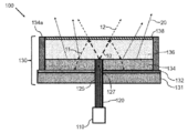
도 1은 광 변환 디바이스(130), 광 가이드(120) 및 레이저(100)를 포함하는 제1 레이저-기반 광원(100)의 주요 스케치를 도시한다. 광 변환 디바이스(130)는 이 경우에 황색 인광체 가넷(YAG:Ce)의 직사각형 블록(대안적으로 원통형 바디 또는 기타 적합한 형상이 사용될 수 있음)인 광 변환기(134)에 부착된 반사 하부 층(132)을 포함한다. 광 변환기(134)는 광 변환기(134)에 대한 냉각을 제공하기 위해 높은 열전도율을 갖는 사파이어로 이루어진 반투명체(136)에 부착된다. 반투명체(136)의 상부 위에는 반사 상부 층(138)이 제공된다. 광 가이드(120)는 광 결합 구조체(125)에 결합된다. 광 결합 구조체(125)는 반사 하부 층(132) 내에 홀 및 광 변환기(134) 내에 캐비티의 형태로 슬롯을 포함한다. 광 가이드(120)의 광 출사 표면은 광 가이드(120)를 통해 레이저(110)에 의해 방출된 레이저 광(10)이 광 결합 표면(127)에 의해 수신되도록 배열된다. 450㎚의 파장을 갖는 레이저 광(10)은 광 변환기(134)의 얇은 층을 통과하여야 한다. 광 결합 표면(127)과 반투명체(136) 사이의 층의 두께는 레이저 광(10)의 5% 미만이 광 변환기(134)의 레이저 피크 방출 파장 또는 온도의 변화들의 영향을 제한하기 위해 변환된 광(20)으로 변환되도록 배열된다. 레이저 광(10)의 나머지 95%는 반투명체(136)를 통해 반사 상부 층의 방향으로 방출된다. 반사 상부 층(138)에 도달한 레이저 광(10)의 25%는 반사 상부 층을 통과한다(투과된 레이저 광(12)). 레이저 광(10)의 나머지는 광 변환기(134)의 방향으로 다시 반사 상부 층(138)에서 반사된다(반사된 레이저 광(11)). 광 변환기(134)는 반사된 레이저 광(11)의 본질적으로 모두를 변환된 광(20)으로 변환한다. 황색 인광체 가넷 내에 발생된 변환된 광(20)은 반사 상부 층(138)의 방향으로 반사 하부 층(132)에서 반사된다. 반사 상부 층(138)은 반사 상부 층(138)에 도달한 모든 변환된 광(20)이 층을 통과할 수 있도록 배열된다. 반사 상부 층(138)은 이 경우에 레이저 광(10)의 일부만이, 그러나 본질적으로 모든 변환된 광이 투과되도록 배열되는 다수의 서브 층을 포함하는 이색성 필터이다. 레이저-기반 광원(100)은 그러므로 투과된 레이저 광(12)과 변환된 광(20)의 혼합을 포함하는 백색 광을 방출한다.Figure 1 illustrates a major sketch of a first laser-based
광 변환 재료의 시트는 바람직하게는 20㎛ 내지 100㎛의 두께를 갖는다. 광 가이드(120)는 보통 50㎛ 내지 100㎛의 직경을 갖는 원형 단면을 갖는다. 반투명체(136)의 두께는 램프 배열 내의 레이저-기반 광원과 결합될 수 있는 광학 디바이스들(예를 들어, 하나 이상의 렌즈, 반사기 등)의 수용 콘을 채우는 투과된 레이저 광(12)을 실현하도록 선택된다.The sheet of the photo-conversion material preferably has a thickness of 20 mu m to 100 mu m. The
전형적인 수들을 갖는 예들:Examples with typical numbers:
광 가이드의 개구수(NA): 0.22.Numerical aperture of light guide (NA): 0.22.
광 가이드(120)의 직경: 100㎛(이것은 50㎛ 코어를 갖는 멀티모드 섬유의 클래딩 층의 직경임)Diameter of the light guide 120: 100 mu m (this is the diameter of the cladding layer of multimode fiber having 50 mu m core)
반투명체(136)의 두께: 200㎛Thickness of the translucent member 136: 200 mu m
광 변환기(134)(루미라믹 플레이트렛)의 두께: 50㎛Thickness of the optical converter 134 (lumilar plate): 50 탆
플레이트렛 크기: 500 × 500㎛2 Plate size: 500 × 500 μm 2
광 가이드(120)의 출사 표면과 이색성 필터 사이의 반투명체 또는 매체의 굴절률(nr)에 따라, 청색 광이 광 변환기(134) 상의 소정의 영역에 걸쳐 분배될 것이다.Depending on the translucency between the exit surface of the
nr=1:nr = 1:
광 가이드(120)의 영역이 없는 광 변환기(134)의 조명된 영역과 광 가이드(120)를 포함하는 전체 영역의 비율은 87%일 것이다(광 결합 표면(127)과 반사 상부 층(138) 사이의 200㎛ 거리에 대해). 이 비율은 본질적으로 변환된 광이 광 결합 표면(127)과 반투명체(136) 사이의 층에 발생되지 않는다는 것을 고려한다(특히 광 결합 표면(127)이 반투명체(136)의 표면인 경우에: 하기의 도 3 내지 6 참조). 비율이 크면 클수록 광 가이드(120)를 통해 더 적은 광이 손실될 수 있다. 조명된 영역의 직경은 이 경우에 280㎛일 것이다.The ratio of the illuminated area of the
nr=1.5인 경우:For nr = 1.5:
광 가이드(120)의 영역이 없는 광 변환기(134)의 조명된 영역과 광 가이드(120)를 포함하는 전체 영역은 79%일 것이다(광 가이드와의 완벽한 광 결합을 가짐). 조명된 영역의 직경은 이 경우에 219㎛일 것이다.The entire area including the
도 2는 황색 인광체 가넷의 흡수 계수(55)를 도시한다. 세로 좌표(51)는 흡수 계수를 표시하고 가로 좌표(52)는 파장을 표시한다. 파장에 걸친 흡수 계수의 스펙트럼은 최근의 자동차 전방 조명 응용들(자동차 헤드라이트)에서 사용되는 것과 같은 황색 인광체 가넷 (Y(3-0.4)Gd0.4,Al5O12:Ce)의 전형적인 흡수 스펙트럼을 나타낸다. 청색 레이저(다이오드) 방출에 대한 전형적인 파장 범위인 440 내지 460㎚에서, 흡수 계수는 2배보다 더 증가하고, 이는 CIE 1976 v' 색점에서 레이저-기반 광원의 약 0.067만큼의 큰 색점 전이(color point shift)에 이르게 할 수 있다. 백색 광에 대해 필요한 청색 레이저 광(10)은 광 변환기(134) 내의 변환 전에 변환되어야 하는 레이저 광(10)의 대부분과 분리된다. 레이저-기반 광원(100)의 광 변환 디바이스(130)는 변환된 광(20)의 방출이 예를 들어, 하기 도 1 및 도 3 내지 6에 도시한 레이저(110)에 의해 방출된 레이저 광(10)의 피크 방출 또는 파장 범위와 본질적으로 독립이도록 배열된다.Figure 2 shows the
도 3은 제2 레이저-기반 광원(100)의 주요 스케치를 도시한다. 기본 배열은 도 1과 관련하여 설명된 것과 동일하다. 광 결합 표면(127)은 본 실시예에서 광 변환기(134)와 반투명체(136) 사이의 계면에 배열된다. 레이저 광(10)은 광 변환기(134)의 어떤 재료도 통과하지 않고 반투명체(136)에 직접 들어간다. 광 변환 디바이스(130)는 히트싱크(131)를 추가로 포함한다. 히트싱크(131)의 표면은 광 변환기(134)에 실리콘에 의해 접착된 반사 하부 층(132)으로서 배열된다. 발광 방향에 본질적으로 수직인 광 변환기(134) 및 이 경우에 또한 반투명체(136)의 측면들은 광이 측면들을 통해 빠져 나갈 수 있는 것을 방지하는 측면 코팅(134a)에 의해 덮힌다. 히트싱크(131)와 유리 또는 대안적으로 사파이어를 포함하는 반투명체(136)의 조합은 100㎛보다 큰 두께를 갖는 광 변환기(134)가 반사 레이저 광(11)의 본질적으로 완전한 광 변환을 가능하게 하기 위해 사용될 수 있도록 광 변환기(134)를 보다 효율적으로 냉각시키기 위해 사용될 수 있다. 추가적인 냉각은 루미라믹 광 변환기(134)의 온도가 150℃ 위로 훨씬 증가하는 것을 방지하고 심각한 열적 급냉을 피한다. 열적 급냉은 광 변환기(134)를 쉽게 파손시킬 수 있다.FIG. 3 shows a main sketch of a second laser-based
도 4는 제3 레이저-기반 광원(100)의 주요 스케치를 도시한다. 기본 배열은 히트싱크(131)를 갖는 도 2와 관련하여 설명된 것과 동일하다. 광 결합 표면(127)은 본 실시예에서 광 결합 구조체(125)가 반투명체(136) 내에 캐비티를 포함하도록 반투명체(136) 내에 약간 배열된다. 반투명체(136)는 유리로 이루어진 하부 반투명 층(136a) 및 유리로 이루어진 상부 반투명 층(136c)을 포함하고 하부 반투명 층(136a)은 광 변환기(134)에 부착되고 상부 반투명 층(136c)은 반사 상부 층(138)에 부착된다. 상부 반투명 층(136c)은 반투명 간격(136b)이 하부 반투명 층(136a)과 상부 반투명 층(136c) 사이에 만들어지도록 캐리어(139)에 추가로 부착된다. 또한, 편향 층(137)이 하부 반투명 층(136a)과 상부 반투명 층(136c) 사이에 배열된다. 편향 층(137)은 이 경우에 레이저 광의 출사 콘이 레이저 광(10)을 편향시킴으로써 넓혀지도록 구조화된 하부 반투명 층(136a)의 표면이다. 광 변환 디바이스(130)의 측면들을 통해 광 손실들을 방지하기 위해 광 변환기(134)의 측면 코팅(134a)뿐만 아니라 캐리어(139)는 반사성이다. 반사 하부 층(132)은 이 경우에 히트싱크(131)와 광 변환기(134) 사이에 배열되고 변환된 광(20)에 대해 반사성이지만 반사된 레이저 광(11)에 대해 본질적으로 투명한 이색성 필터이다. 광 변환기(134)에서 변환되지 않은 반사된 레이저 광(11)은 반사 하부 층(132)을 통과하고 히트싱크(131)에 의해 흡수된다.FIG. 4 shows a main sketch of a third laser-based
도 5는 투사 응용들을 위한 광원으로서 사용될 수 있는 제4 레이저-기반 광원(100)의 주요 스케치를 도시한다. 기본 배열은 히트싱크(131)를 갖는 도 2와 관련하여 설명된 배열과 매우 유사하다. 반사 상부 층(138)은 본질적으로 단지 변환된 광(20)이 반사 상부 층(138)을 통과하도록 레이저 광(10)의 적어도 99%를 반사한다. 광원의 색점은 그러므로 변환된 광(20)의 파장 범위에 의해 결정된다. 광 변환 디바이스(130)는 광 변환기(134)와 반투명체(136) 사이에 배열된 반사 방지 층(135)을 추가로 포함한다. 반사 방지 층(135)은 반투명체(136)와 광 변환기(134) 사이의 계면에서의 반사 레이저 광(11)의 반사를 억제한다.FIG. 5 illustrates a major sketch of a fourth laser-based
전형적인 수들로 위에 제공된 예들은 또한 하기 도 5 또는 도 6에 따른 레이저-기반 광원(100)에도 적용된다.The examples provided above with typical numbers also apply to the laser-based
도 6은 제5 레이저-기반 광원(100)의 주요 스케치를 도시한다. 기본 배열은 도 5와 관련하여 설명된 배열과 동일하지만 광 변환 디바이스(130)는 광 변환기(134)와 반투명체(136) 사이에 반사 방지 층(135)을 포함하지 않는다. 광 흡수 층(133)은 투과된 레이저 광(12)이 레이저-기반 광원(100)에 의해 방출된 변환된 광(20)의 양호한 색 포화를 가능하게 하기 위해 반사 상부 층(138)을 통과한 후에 광 흡수 층(133) 내에 흡수되도록 반사 상부 층(138)의 상부 측에 부착된다.FIG. 6 shows a main sketch of a fifth laser-based
광 흡수 층(133) 또는 색 필터 층은 레이저-기반 광원(100)의 의도된 색 방출에 따라 선택된다. 색 필터 층들은 바람직하게는 다음과 같은 무기 색소 재료들이다:The light
청색: CoO-Al2O3 Blue: CoO-Al 2 O 3
군청색 Navy blue
녹색: TiO2-CoO-NiO-ZrO2 Green: TiO 2 -CoO-NiO-ZrO 2
CeO-Cr2O3-TiO2- Al2O3 CeO-Cr 2 O 3 -TiO 2 - Al 2 O 3
TiO2-ZnO-CoO-NiOTiO 2 -ZnO-CoO-NiO
황색: Bi-바나듐산염Yellow: Bi-vanadate
Pr,Z,Si 산화물 Pr, Z, Si oxide
Ti,Sb, Cr 산화물 Ti, Sb, Cr oxides
Ta 산화질화물 Ta oxynitride
적색: Fe2O3 Red: Fe 2 O 3
Zn,Cr,Fe -산화물 Zn, Cr, Fe - oxide
CdS-CdSe CdS-CdSe
Ta ON Ta ON
이들 재료는 바람직하게는 광의 후방산란으로 인한 광 손실들을 피하기 위해, 입자 직경들<200㎚인 것으로 사용된다.These materials are preferably used with particle diameters < 200 nm to avoid light losses due to backscattering of light.
부가적으로, 금속 프탈로시아닌들 또는 페릴린들의 그룹으로부터 선택될 수 있는 온도 안정 유기 색소가 적용될 수 있다.In addition, temperature stable organic pigments can be applied which can be selected from the group of metal phthalocyanines or perillins.
광 결합 구조체(125) 및 특히 광 결합 표면(127)의 위치는 램프(예를 들어, 차량 헤드라이트, 투사 램프...)의 전체적인 배열에 적응될 수 있다. 그러므로 광 변환기(120)는 도 1 및 도 3-6에 도시한 것과 같은 광 변환기(134)의 중심 내에 배열될 필요는 없다. 또한, 광 가이드(120) 및 광 변환기(134)는 도 1 및 도 3-6에 도시한 90°와 상이한 각도를 둘러쌀 수 있다.The location of the
본 발명이 도면 및 전술한 설명에서 상세히 예시되고 설명되었지만, 이러한 예시 및 설명은 설명적이거나 예시적인 것이지 제한적인 것으로 고려되지 않는다.While the invention has been illustrated and described in detail in the drawings and foregoing description, such illustration and description is illustrative or exemplary and not restrictive.
본 개시내용을 읽고 난 다음에, 다른 수정들은 본 기술 분야의 기술자들에게 분명해질 것이다. 이러한 수정들은 본 기술 분야에 이미 공지되고 여기에 이미 설명된 특징들 대신에 또는 그들 외에 사용될 수 있는 다른 특징들을 포함할 수 있다.Having read the present disclosure, other modifications will become apparent to those skilled in the art. These modifications may include other features that may be used in place of or in addition to the features already known in the art and already described herein.
개시된 실시예들에 대한 변화들이 도면, 개시내용 및 첨부된 청구범위를 연구한다면 본 기술 분야의 기술자들에 의해 이해되고 실행될 수 있다. 청구범위에서, 단어 "포함하는"은 다른 요소들 또는 단계들을 배제하지 않고, 단수 표현은 복수의 요소 또는 단계를 배제하지 않는다. 소정의 수단들이 상호 상이한 종속 청구항들에 나열된 사실만으로 이들 수단의 조합이 유리하게 사용될 수 없다는 것을 나타내지 않는다.Variations to the disclosed embodiments may be understood and effected by those skilled in the art if the drawings, the disclosure, and the appended claims are studied. In the claims, the word "comprising" does not exclude other elements or steps, and the singular presentation does not exclude a plurality of elements or steps. Does not indicate that certain combinations of these means can not be used to advantage merely the fact that certain means are listed in mutually different dependent claims.
청구범위 내의 임의의 참조 부호들은 그 범위를 제한하는 것으로 해석되지 않아야 한다.Any reference signs in the claims shall not be construed as limiting the scope thereof.
10
레이저 광
11
반사된 레이저 광
12
투과된 레이저 광
20
변환된 광
51
흡수
52
파장
55
YAG:Ce 인광체의 흡수 계수
100
레이저-기반 광원
110
레이저
120
광 가이드
125
광 결합 구조체
127
광 결합 표면
130
광 변환 디바이스
131
히트싱크
132
반사 하부 층
133
광 흡수 층
134
광 변환기
134a
측면 코팅
135
반사 방지 층
136
반투명체
136a
하부 반투명 층
136b
반투명 간격
136c
상부 반투명 층
137
편향 층
138
반사 상부 층
139
캐리어10 laser light
11 Reflected laser light
12 Transmitted laser light
20 converted light
51 absorption
52 Wavelength
The absorption coefficient of 55 YAG: Ce phosphor
100 laser-based light source
110 laser
120 light guide
125 optical coupling structure
127 optically coupled surface
130 photoconversion device
131 heat sink
132 reflection bottom layer
133 light absorbing layer
134 optical converter
134a side coating
135 Antireflection layer
136 Translucent
136a Lower translucent layer
136b Translucent gap
136c upper translucent layer
137 deflection layer
138 reflective upper layer
139 carrier
Claims (12)
Applications Claiming Priority (3)
| Application Number | Priority Date | Filing Date | Title |
|---|---|---|---|
| EP16172909.0 | 2016-06-03 | ||
| EP16172909 | 2016-06-03 | ||
| PCT/EP2017/062396 WO2017207347A1 (en) | 2016-06-03 | 2017-05-23 | Light converting device |
Publications (2)
| Publication Number | Publication Date |
|---|---|
| KR20190014066A true KR20190014066A (en) | 2019-02-11 |
| KR102352759B1 KR102352759B1 (en) | 2022-01-19 |
Family
ID=56131336
Family Applications (1)
| Application Number | Title | Priority Date | Filing Date |
|---|---|---|---|
| KR1020197000042A Active KR102352759B1 (en) | 2016-06-03 | 2017-05-23 | light conversion device |
Country Status (7)
| Country | Link |
|---|---|
| US (1) | US10648632B2 (en) |
| EP (1) | EP3465844B1 (en) |
| JP (1) | JP6986523B2 (en) |
| KR (1) | KR102352759B1 (en) |
| CN (1) | CN109196738B (en) |
| TW (1) | TWI737740B (en) |
| WO (1) | WO2017207347A1 (en) |
Families Citing this family (4)
| Publication number | Priority date | Publication date | Assignee | Title |
|---|---|---|---|---|
| WO2019162147A1 (en) | 2018-02-20 | 2019-08-29 | Lumileds Holding B.V. | Light converting device with confined light converter |
| US10903398B2 (en) | 2019-02-06 | 2021-01-26 | Osram Opto Semiconductors Gmbh | Dielectric film coating for full conversion ceramic platelets |
| WO2023127789A1 (en) * | 2021-12-28 | 2023-07-06 | 市光工業株式会社 | Light source unit for vehicular lighting tool and vehicular lighting tool |
| JP7658268B2 (en) * | 2021-12-28 | 2025-04-08 | 市光工業株式会社 | Light source unit for vehicle lamp and vehicle lamp |
Citations (2)
| Publication number | Priority date | Publication date | Assignee | Title |
|---|---|---|---|---|
| US20100172148A1 (en) * | 2009-01-07 | 2010-07-08 | Olympus Corporation | Light source device |
| US20110280032A1 (en) * | 2010-05-17 | 2011-11-17 | Sharp Kabushiki Kaisha | Light-emitting device, illumination device, and vehicle headlight |
Family Cites Families (11)
| Publication number | Priority date | Publication date | Assignee | Title |
|---|---|---|---|---|
| JP4375270B2 (en) * | 2005-02-08 | 2009-12-02 | 日亜化学工業株式会社 | Light emitting device |
| EP1672755B1 (en) * | 2004-12-17 | 2015-09-23 | Nichia Corporation | Light emitting device |
| JP4720177B2 (en) * | 2004-12-17 | 2011-07-13 | 日亜化学工業株式会社 | Light emitting device |
| JP5124908B2 (en) * | 2005-03-10 | 2013-01-23 | 日亜化学工業株式会社 | Light emitting device |
| US7942556B2 (en) * | 2007-06-18 | 2011-05-17 | Xicato, Inc. | Solid state illumination device |
| WO2010049875A1 (en) * | 2008-10-30 | 2010-05-06 | Koninklijke Philips Electronics N.V. | Laser lighting device |
| US8833975B2 (en) * | 2010-09-07 | 2014-09-16 | Sharp Kabushiki Kaisha | Light-emitting device, illuminating device, vehicle headlamp, and method for producing light-emitting device |
| DE102012005658B4 (en) * | 2012-03-22 | 2013-10-24 | Schott Ag | White light generation |
| DE102012005657B4 (en) * | 2012-03-22 | 2020-06-10 | Schott Ag | White light lighting device |
| JP6538178B2 (en) * | 2015-09-03 | 2019-07-03 | シャープ株式会社 | Light emitting device |
| JP6688306B2 (en) * | 2015-09-03 | 2020-04-28 | シャープ株式会社 | Light emitter and lighting device |
-
2017
- 2017-05-23 WO PCT/EP2017/062396 patent/WO2017207347A1/en not_active Ceased
- 2017-05-23 CN CN201780034412.9A patent/CN109196738B/en active Active
- 2017-05-23 JP JP2018562224A patent/JP6986523B2/en active Active
- 2017-05-23 US US16/306,310 patent/US10648632B2/en active Active
- 2017-05-23 KR KR1020197000042A patent/KR102352759B1/en active Active
- 2017-05-23 EP EP17725943.9A patent/EP3465844B1/en active Active
- 2017-05-31 TW TW106117853A patent/TWI737740B/en active
Patent Citations (2)
| Publication number | Priority date | Publication date | Assignee | Title |
|---|---|---|---|---|
| US20100172148A1 (en) * | 2009-01-07 | 2010-07-08 | Olympus Corporation | Light source device |
| US20110280032A1 (en) * | 2010-05-17 | 2011-11-17 | Sharp Kabushiki Kaisha | Light-emitting device, illumination device, and vehicle headlight |
Also Published As
| Publication number | Publication date |
|---|---|
| EP3465844B1 (en) | 2025-03-19 |
| KR102352759B1 (en) | 2022-01-19 |
| CN109196738B (en) | 2021-08-03 |
| CN109196738A (en) | 2019-01-11 |
| TWI737740B (en) | 2021-09-01 |
| JP6986523B2 (en) | 2021-12-22 |
| EP3465844A1 (en) | 2019-04-10 |
| WO2017207347A1 (en) | 2017-12-07 |
| JP2019519921A (en) | 2019-07-11 |
| TW201803238A (en) | 2018-01-16 |
| US20190137063A1 (en) | 2019-05-09 |
| US10648632B2 (en) | 2020-05-12 |
Similar Documents
| Publication | Publication Date | Title |
|---|---|---|
| US8067884B2 (en) | LED lighting arrangement including a substantially spherical optical component having a surface partially coated with a light emitting phosphor | |
| US10378701B2 (en) | Light emitting device | |
| US11868023B2 (en) | Light-emitting device and optical fiber | |
| KR102352759B1 (en) | light conversion device | |
| KR20180095645A (en) | Wavelength converting member and light emitting device | |
| JP6631855B2 (en) | Light emitting device | |
| KR20180083380A (en) | Wavelength converting member and light emitting device | |
| CN111486406B (en) | Light-emitting device and car lamp using same | |
| JP4592457B2 (en) | Red phosphor and light emitting device using the same | |
| JP7117504B2 (en) | light emitting device | |
| JP7016034B2 (en) | Luminescent device | |
| US11022277B2 (en) | Wavelength converter and lighting apparatus | |
| US20210091274A1 (en) | Wavelength conversion member and light emitting device | |
| KR101848842B1 (en) | Laser lighting apparatus | |
| JP2012119121A (en) | Light source device and lighting system | |
| KR20160129448A (en) | Laser lighting apparatus |
Legal Events
| Date | Code | Title | Description |
|---|---|---|---|
| PA0105 | International application |
St.27 status event code: A-0-1-A10-A15-nap-PA0105 |
|
| PG1501 | Laying open of application |
St.27 status event code: A-1-1-Q10-Q12-nap-PG1501 |
|
| A201 | Request for examination | ||
| P11-X000 | Amendment of application requested |
St.27 status event code: A-2-2-P10-P11-nap-X000 |
|
| P13-X000 | Application amended |
St.27 status event code: A-2-2-P10-P13-nap-X000 |
|
| PA0201 | Request for examination |
St.27 status event code: A-1-2-D10-D11-exm-PA0201 |
|
| D13-X000 | Search requested |
St.27 status event code: A-1-2-D10-D13-srh-X000 |
|
| D14-X000 | Search report completed |
St.27 status event code: A-1-2-D10-D14-srh-X000 |
|
| E902 | Notification of reason for refusal | ||
| PE0902 | Notice of grounds for rejection |
St.27 status event code: A-1-2-D10-D21-exm-PE0902 |
|
| E13-X000 | Pre-grant limitation requested |
St.27 status event code: A-2-3-E10-E13-lim-X000 |
|
| P11-X000 | Amendment of application requested |
St.27 status event code: A-2-2-P10-P11-nap-X000 |
|
| P13-X000 | Application amended |
St.27 status event code: A-2-2-P10-P13-nap-X000 |
|
| E701 | Decision to grant or registration of patent right | ||
| PE0701 | Decision of registration |
St.27 status event code: A-1-2-D10-D22-exm-PE0701 |
|
| GRNT | Written decision to grant | ||
| PR0701 | Registration of establishment |
St.27 status event code: A-2-4-F10-F11-exm-PR0701 |
|
| PR1002 | Payment of registration fee |
St.27 status event code: A-2-2-U10-U12-oth-PR1002 Fee payment year number: 1 |
|
| PG1601 | Publication of registration |
St.27 status event code: A-4-4-Q10-Q13-nap-PG1601 |
|
| P22-X000 | Classification modified |
St.27 status event code: A-4-4-P10-P22-nap-X000 |
|
| PR1001 | Payment of annual fee |
St.27 status event code: A-4-4-U10-U11-oth-PR1001 Fee payment year number: 4 |
|
| PR1001 | Payment of annual fee |
St.27 status event code: A-4-4-U10-U11-oth-PR1001 Fee payment year number: 5 |
|
| U11 | Full renewal or maintenance fee paid |
Free format text: ST27 STATUS EVENT CODE: A-4-4-U10-U11-OTH-PR1001 (AS PROVIDED BY THE NATIONAL OFFICE) Year of fee payment: 5 |