KR20180057566A - Method and apparatus for encoding/decoding image and recording medium for storing bitstream - Google Patents
Method and apparatus for encoding/decoding image and recording medium for storing bitstream Download PDFInfo
- Publication number
- KR20180057566A KR20180057566A KR1020170156552A KR20170156552A KR20180057566A KR 20180057566 A KR20180057566 A KR 20180057566A KR 1020170156552 A KR1020170156552 A KR 1020170156552A KR 20170156552 A KR20170156552 A KR 20170156552A KR 20180057566 A KR20180057566 A KR 20180057566A
- Authority
- KR
- South Korea
- Prior art keywords
- picture
- prediction
- intra
- current block
- inter
- Prior art date
- Legal status (The legal status is an assumption and is not a legal conclusion. Google has not performed a legal analysis and makes no representation as to the accuracy of the status listed.)
- Ceased
Links
Images






Classifications
-
- H—ELECTRICITY
- H04—ELECTRIC COMMUNICATION TECHNIQUE
- H04N—PICTORIAL COMMUNICATION, e.g. TELEVISION
- H04N19/00—Methods or arrangements for coding, decoding, compressing or decompressing digital video signals
- H04N19/10—Methods or arrangements for coding, decoding, compressing or decompressing digital video signals using adaptive coding
- H04N19/102—Methods or arrangements for coding, decoding, compressing or decompressing digital video signals using adaptive coding characterised by the element, parameter or selection affected or controlled by the adaptive coding
- H04N19/103—Selection of coding mode or of prediction mode
- H04N19/105—Selection of the reference unit for prediction within a chosen coding or prediction mode, e.g. adaptive choice of position and number of pixels used for prediction
-
- H—ELECTRICITY
- H04—ELECTRIC COMMUNICATION TECHNIQUE
- H04N—PICTORIAL COMMUNICATION, e.g. TELEVISION
- H04N19/00—Methods or arrangements for coding, decoding, compressing or decompressing digital video signals
- H04N19/10—Methods or arrangements for coding, decoding, compressing or decompressing digital video signals using adaptive coding
- H04N19/102—Methods or arrangements for coding, decoding, compressing or decompressing digital video signals using adaptive coding characterised by the element, parameter or selection affected or controlled by the adaptive coding
- H04N19/103—Selection of coding mode or of prediction mode
- H04N19/107—Selection of coding mode or of prediction mode between spatial and temporal predictive coding, e.g. picture refresh
-
- H—ELECTRICITY
- H04—ELECTRIC COMMUNICATION TECHNIQUE
- H04N—PICTORIAL COMMUNICATION, e.g. TELEVISION
- H04N19/00—Methods or arrangements for coding, decoding, compressing or decompressing digital video signals
- H04N19/10—Methods or arrangements for coding, decoding, compressing or decompressing digital video signals using adaptive coding
- H04N19/102—Methods or arrangements for coding, decoding, compressing or decompressing digital video signals using adaptive coding characterised by the element, parameter or selection affected or controlled by the adaptive coding
- H04N19/103—Selection of coding mode or of prediction mode
- H04N19/11—Selection of coding mode or of prediction mode among a plurality of spatial predictive coding modes
-
- H—ELECTRICITY
- H04—ELECTRIC COMMUNICATION TECHNIQUE
- H04N—PICTORIAL COMMUNICATION, e.g. TELEVISION
- H04N19/00—Methods or arrangements for coding, decoding, compressing or decompressing digital video signals
- H04N19/10—Methods or arrangements for coding, decoding, compressing or decompressing digital video signals using adaptive coding
- H04N19/102—Methods or arrangements for coding, decoding, compressing or decompressing digital video signals using adaptive coding characterised by the element, parameter or selection affected or controlled by the adaptive coding
- H04N19/117—Filters, e.g. for pre-processing or post-processing
-
- H—ELECTRICITY
- H04—ELECTRIC COMMUNICATION TECHNIQUE
- H04N—PICTORIAL COMMUNICATION, e.g. TELEVISION
- H04N19/00—Methods or arrangements for coding, decoding, compressing or decompressing digital video signals
- H04N19/10—Methods or arrangements for coding, decoding, compressing or decompressing digital video signals using adaptive coding
- H04N19/102—Methods or arrangements for coding, decoding, compressing or decompressing digital video signals using adaptive coding characterised by the element, parameter or selection affected or controlled by the adaptive coding
- H04N19/132—Sampling, masking or truncation of coding units, e.g. adaptive resampling, frame skipping, frame interpolation or high-frequency transform coefficient masking
-
- H—ELECTRICITY
- H04—ELECTRIC COMMUNICATION TECHNIQUE
- H04N—PICTORIAL COMMUNICATION, e.g. TELEVISION
- H04N19/00—Methods or arrangements for coding, decoding, compressing or decompressing digital video signals
- H04N19/10—Methods or arrangements for coding, decoding, compressing or decompressing digital video signals using adaptive coding
- H04N19/134—Methods or arrangements for coding, decoding, compressing or decompressing digital video signals using adaptive coding characterised by the element, parameter or criterion affecting or controlling the adaptive coding
- H04N19/136—Incoming video signal characteristics or properties
- H04N19/137—Motion inside a coding unit, e.g. average field, frame or block difference
- H04N19/139—Analysis of motion vectors, e.g. their magnitude, direction, variance or reliability
-
- H—ELECTRICITY
- H04—ELECTRIC COMMUNICATION TECHNIQUE
- H04N—PICTORIAL COMMUNICATION, e.g. TELEVISION
- H04N19/00—Methods or arrangements for coding, decoding, compressing or decompressing digital video signals
- H04N19/10—Methods or arrangements for coding, decoding, compressing or decompressing digital video signals using adaptive coding
- H04N19/134—Methods or arrangements for coding, decoding, compressing or decompressing digital video signals using adaptive coding characterised by the element, parameter or criterion affecting or controlling the adaptive coding
- H04N19/146—Data rate or code amount at the encoder output
-
- H—ELECTRICITY
- H04—ELECTRIC COMMUNICATION TECHNIQUE
- H04N—PICTORIAL COMMUNICATION, e.g. TELEVISION
- H04N19/00—Methods or arrangements for coding, decoding, compressing or decompressing digital video signals
- H04N19/10—Methods or arrangements for coding, decoding, compressing or decompressing digital video signals using adaptive coding
- H04N19/134—Methods or arrangements for coding, decoding, compressing or decompressing digital video signals using adaptive coding characterised by the element, parameter or criterion affecting or controlling the adaptive coding
- H04N19/157—Assigned coding mode, i.e. the coding mode being predefined or preselected to be further used for selection of another element or parameter
- H04N19/159—Prediction type, e.g. intra-frame, inter-frame or bidirectional frame prediction
-
- H—ELECTRICITY
- H04—ELECTRIC COMMUNICATION TECHNIQUE
- H04N—PICTORIAL COMMUNICATION, e.g. TELEVISION
- H04N19/00—Methods or arrangements for coding, decoding, compressing or decompressing digital video signals
- H04N19/10—Methods or arrangements for coding, decoding, compressing or decompressing digital video signals using adaptive coding
- H04N19/169—Methods or arrangements for coding, decoding, compressing or decompressing digital video signals using adaptive coding characterised by the coding unit, i.e. the structural portion or semantic portion of the video signal being the object or the subject of the adaptive coding
- H04N19/17—Methods or arrangements for coding, decoding, compressing or decompressing digital video signals using adaptive coding characterised by the coding unit, i.e. the structural portion or semantic portion of the video signal being the object or the subject of the adaptive coding the unit being an image region, e.g. an object
- H04N19/172—Methods or arrangements for coding, decoding, compressing or decompressing digital video signals using adaptive coding characterised by the coding unit, i.e. the structural portion or semantic portion of the video signal being the object or the subject of the adaptive coding the unit being an image region, e.g. an object the region being a picture, frame or field
-
- H—ELECTRICITY
- H04—ELECTRIC COMMUNICATION TECHNIQUE
- H04N—PICTORIAL COMMUNICATION, e.g. TELEVISION
- H04N19/00—Methods or arrangements for coding, decoding, compressing or decompressing digital video signals
- H04N19/10—Methods or arrangements for coding, decoding, compressing or decompressing digital video signals using adaptive coding
- H04N19/169—Methods or arrangements for coding, decoding, compressing or decompressing digital video signals using adaptive coding characterised by the coding unit, i.e. the structural portion or semantic portion of the video signal being the object or the subject of the adaptive coding
- H04N19/17—Methods or arrangements for coding, decoding, compressing or decompressing digital video signals using adaptive coding characterised by the coding unit, i.e. the structural portion or semantic portion of the video signal being the object or the subject of the adaptive coding the unit being an image region, e.g. an object
- H04N19/176—Methods or arrangements for coding, decoding, compressing or decompressing digital video signals using adaptive coding characterised by the coding unit, i.e. the structural portion or semantic portion of the video signal being the object or the subject of the adaptive coding the unit being an image region, e.g. an object the region being a block, e.g. a macroblock
-
- H—ELECTRICITY
- H04—ELECTRIC COMMUNICATION TECHNIQUE
- H04N—PICTORIAL COMMUNICATION, e.g. TELEVISION
- H04N19/00—Methods or arrangements for coding, decoding, compressing or decompressing digital video signals
- H04N19/10—Methods or arrangements for coding, decoding, compressing or decompressing digital video signals using adaptive coding
- H04N19/169—Methods or arrangements for coding, decoding, compressing or decompressing digital video signals using adaptive coding characterised by the coding unit, i.e. the structural portion or semantic portion of the video signal being the object or the subject of the adaptive coding
- H04N19/182—Methods or arrangements for coding, decoding, compressing or decompressing digital video signals using adaptive coding characterised by the coding unit, i.e. the structural portion or semantic portion of the video signal being the object or the subject of the adaptive coding the unit being a pixel
-
- H—ELECTRICITY
- H04—ELECTRIC COMMUNICATION TECHNIQUE
- H04N—PICTORIAL COMMUNICATION, e.g. TELEVISION
- H04N19/00—Methods or arrangements for coding, decoding, compressing or decompressing digital video signals
- H04N19/46—Embedding additional information in the video signal during the compression process
-
- H—ELECTRICITY
- H04—ELECTRIC COMMUNICATION TECHNIQUE
- H04N—PICTORIAL COMMUNICATION, e.g. TELEVISION
- H04N19/00—Methods or arrangements for coding, decoding, compressing or decompressing digital video signals
- H04N19/50—Methods or arrangements for coding, decoding, compressing or decompressing digital video signals using predictive coding
- H04N19/503—Methods or arrangements for coding, decoding, compressing or decompressing digital video signals using predictive coding involving temporal prediction
- H04N19/51—Motion estimation or motion compensation
- H04N19/513—Processing of motion vectors
-
- H—ELECTRICITY
- H04—ELECTRIC COMMUNICATION TECHNIQUE
- H04N—PICTORIAL COMMUNICATION, e.g. TELEVISION
- H04N19/00—Methods or arrangements for coding, decoding, compressing or decompressing digital video signals
- H04N19/50—Methods or arrangements for coding, decoding, compressing or decompressing digital video signals using predictive coding
- H04N19/503—Methods or arrangements for coding, decoding, compressing or decompressing digital video signals using predictive coding involving temporal prediction
- H04N19/51—Motion estimation or motion compensation
- H04N19/513—Processing of motion vectors
- H04N19/517—Processing of motion vectors by encoding
- H04N19/52—Processing of motion vectors by encoding by predictive encoding
-
- H—ELECTRICITY
- H04—ELECTRIC COMMUNICATION TECHNIQUE
- H04N—PICTORIAL COMMUNICATION, e.g. TELEVISION
- H04N19/00—Methods or arrangements for coding, decoding, compressing or decompressing digital video signals
- H04N19/70—Methods or arrangements for coding, decoding, compressing or decompressing digital video signals characterised by syntax aspects related to video coding, e.g. related to compression standards
-
- H—ELECTRICITY
- H04—ELECTRIC COMMUNICATION TECHNIQUE
- H04N—PICTORIAL COMMUNICATION, e.g. TELEVISION
- H04N19/00—Methods or arrangements for coding, decoding, compressing or decompressing digital video signals
- H04N19/85—Methods or arrangements for coding, decoding, compressing or decompressing digital video signals using pre-processing or post-processing specially adapted for video compression
- H04N19/86—Methods or arrangements for coding, decoding, compressing or decompressing digital video signals using pre-processing or post-processing specially adapted for video compression involving reduction of coding artifacts, e.g. of blockiness
Landscapes
- Engineering & Computer Science (AREA)
- Multimedia (AREA)
- Signal Processing (AREA)
- Compression Or Coding Systems Of Tv Signals (AREA)
Abstract
영상 부호화/복호화 방법 및 장치가 제공될 수 있다. 본 발명에 따른 영상 부호화 장치에 의해 수행되는 영상 부호화 방법은, 현재 블록의 화면 내 예측 모드를 결정하는 단계, 현재 픽처 내 상기 현재 블록의 인접 화소 및 참조 픽처의 화소 중 적어도 하나를 이용하여 화면 내 예측의 참조 샘플을 구성하는 단계, 상기 화면 내 예측 모드 및 상기 참조 샘플에 기초하여 상기 현재 블록에 대한 화면 내 예측을 수행하는 단계를 포함할 수 있다.A video encoding / decoding method and apparatus may be provided. An image encoding method performed by an image encoding apparatus according to the present invention includes the steps of: determining an intra-picture prediction mode of a current block; determining, by using at least one of a neighboring pixel of the current block and a reference picture, Constructing a reference sample of the prediction, and performing intra-picture prediction on the current block based on the intra-picture prediction mode and the reference sample.
Description
본 발명은 영상 부호화/복호화 방법, 장치 및 비트스트림을 저장한 기록 매체에 관한 것이다. 구체적으로, 본 발명은 참조 픽처의 화소를 이용하여 화면 내 예측을 수행하는 영상 부호화/복호화 방법, 장치 및 본 발명의 영상 부호화 방법 또는 장치에 의해 생성된 비트스트림을 저장한 기록 매체에 관한 것이다.The present invention relates to a video encoding / decoding method, an apparatus, and a recording medium storing a bitstream. Specifically, the present invention relates to a video encoding / decoding method and apparatus for performing intra-picture prediction using pixels of a reference picture, and a recording medium storing a bit stream generated by the video encoding method or apparatus of the present invention.
최근 HD(High Definition) 영상 및 UHD(Ultra High Definition) 영상과 같은 고해상도, 고품질의 영상에 대한 수요가 다양한 응용 분야에서 증가하고 있다. 영상 데이터가 고해상도, 고품질이 될수록 기존의 영상 데이터에 비해 상대적으로 데이터량이 증가하기 때문에 기존의 유무선 광대역 회선과 같은 매체를 이용하여 영상 데이터를 전송하거나 기존의 저장 매체를 이용해 저장하는 경우, 전송 비용과 저장 비용이 증가하게 된다. 영상 데이터가 고해상도, 고품질화 됨에 따라 발생하는 이러한 문제들을 해결하기 위해서는 더 높은 해상도 및 화질을 갖는 영상에 대한 고효율 영상 부호화(encoding)/복호화(decoding) 기술이 요구된다. Recently, the demand for high resolution and high quality images such as high definition (HD) image and ultra high definition (UHD) image is increasing in various applications. As the image data has high resolution and high quality, the amount of data increases relative to the existing image data. Therefore, when the image data is transmitted using a medium such as a wired / wireless broadband line or stored using an existing storage medium, The storage cost is increased. In order to solve such problems caused by high-resolution and high-quality image data, a high-efficiency image encoding / decoding technique for an image having higher resolution and image quality is required.
영상 압축 기술로 현재 픽처의 이전 또는 이후 픽처로부터 현재 픽처에 포함된 화소값을 예측하는 화면 간 예측 기술, 현재 픽처 내의 화소 정보를 이용하여 현재 픽처에 포함된 화소값을 예측하는 화면 내 예측 기술, 잔여 신호의 에너지를 압축하기 위한 변환 및 양자화 기술, 출현 빈도가 높은 값에 짧은 부호를 할당하고 출현 빈도가 낮은 값에 긴 부호를 할당하는 엔트로피 부호화 기술 등 다양한 기술이 존재하고 이러한 영상 압축 기술을 이용해 영상 데이터를 효과적으로 압축하여 전송 또는 저장할 수 있다. An inter picture prediction technique for predicting a pixel value included in a current picture from a previous or a subsequent picture of a current picture by an image compression technique, an intra picture prediction technique for predicting a pixel value included in a current picture using pixel information in a current picture, There are various techniques such as a transformation and quantization technique for compressing the energy of the residual signal, an entropy coding technique for assigning a short code to a value having a high appearance frequency, and a long code to a value having a low appearance frequency. The image data can be effectively compressed and transmitted or stored.
본 발명은 압축 효율이 향상된 영상 부호화/복호화 방법 및 장치를 제공하는 것을 목적으로 한다.An object of the present invention is to provide an image encoding / decoding method and apparatus with improved compression efficiency.
또한, 본 발명은 참조 픽처의 화소를 이용하여 화면 내 예측을 수행하는 영상 부호화/복호화 방법 및 장치를 제공하는 것을 목적으로 한다.It is another object of the present invention to provide an image encoding / decoding method and apparatus for performing intra-picture prediction using pixels of a reference picture.
또한, 본 발명은 본 발명의 영상 부호화 방법 또는 장치에 의해 생성된 비트스트림을 저장한 기록 매체를 제공하는 것을 목적으로 한다.It is another object of the present invention to provide a recording medium storing a bit stream generated by the image encoding method or apparatus of the present invention.
본 발명에 따른, 영상 부호화 장치에 의해 수행되는 영상 부호화 방법은 현재 블록의 화면 내 예측 모드를 결정하는 단계, 현재 픽처 내 상기 현재 블록의 인접 화소 및 참조 픽처의 화소 중 적어도 하나를 이용하여 화면 내 예측의 참조 샘플을 구성하는 단계, 및 상기 화면 내 예측 모드 및 상기 참조 샘플에 기초하여 상기 현재 블록에 대한 화면 내 예측을 수행하는 단계를 포함할 수 있다.According to another aspect of the present invention, there is provided an image encoding method performed by an image encoding apparatus, comprising the steps of: determining an intra-picture prediction mode of a current block; determining, by using at least one of adjacent pixels of the current block and pixels of a reference picture, Constructing a reference sample of the prediction, and performing intra-picture prediction on the current block based on the intra-picture prediction mode and the reference sample.
본 발명에 따른 영상 부호화 방법에 있어서, 상기 참조 픽처의 화소는 상기 현재 블록의 상기 참조 픽처 내 유사 영역에 포함된 화소일 수 있다.In the image coding method according to the present invention, the pixel of the reference picture may be a pixel included in the similar area in the reference picture of the current block.
본 발명에 따른 영상 부호화 방법에 있어서, 상기 참조 픽처 내 유사 영역은, 상기 현재 블록 및 상기 참조 픽처를 이용한 유사도 계산에 기초하여 특정될 수 있다.In the image encoding method according to the present invention, the similar intra-reference area may be specified based on the similarity calculation using the current block and the reference picture.
본 발명에 따른 영상 부호화 방법에 있어서, 상기 참조 픽처 내 유사 영역은, 상기 현재 블록과 동일 위치를 갖는 상기 참조 픽처 내 영역일 수 있다.In the image encoding method according to the present invention, the similar intra-reference area may be the intra-reference picture area having the same position as the current block.
본 발명에 따른 영상 부호화 방법에 있어서, 상기 참조 픽처 내 유사 영역은, 상기 현재 블록의 주변 블록의 예측 정보에 기초하여 특정될 수 있다.In the image encoding method according to the present invention, the intra-reference picture similar area may be specified based on prediction information of a neighboring block of the current block.
본 발명에 따른 영상 부호화 방법은, 상기 참조 픽처 내 유사 영역을 특정하기 위한 정보를 부호화하는 단계를 더 포함할 수 있다.The image encoding method according to the present invention may further include encoding information for specifying the similar area in the reference picture.
본 발명에 따른 영상 부호화 방법에 있어서, 상기 화면 내 예측 모드 중 방향성 모드는 전방향의 예측을 사용하는 방향성 모드를 포함하고, 하나의 방향성 모드와 180도 대칭되는 방향의 방향성 모드에 대해 동일한 화면 내 예측 모드 번호가 부여될 수 있다.In the image encoding method according to the present invention, the directional mode of the intra-picture prediction mode includes a directional mode using a forward direction prediction and a directional mode using a one directional mode and a directional mode 180- A prediction mode number can be given.
본 발명에 따른 영상 부호화 방법은, 상기 화면 내 예측 방향이 상기 현재 블록의 우측 또는 하단을 지시하는 방향인지 여부를 나타내는 정보를 부호화하는 단계를 더 포함할 수 있다.The image coding method according to the present invention may further comprise the step of coding information indicating whether the intra-picture prediction direction is the direction indicating the right or the bottom of the current block.
본 발명에 따른 영상 부호화 방법에 있어서, 상기 참조 샘플을 구성하는 단계는, 상기 참조 픽처의 화소를 이용하여, 비가용 참조 샘플을 패딩하는 단계 또는 구성된 참조 샘플을 필터링하는 단계를 포함할 수 있다.In the image encoding method according to the present invention, the step of constructing the reference sample may include the step of padding the unused reference sample using the pixels of the reference picture, or filtering the constructed reference sample.
본 발명에 따른 영상 부호화 장치는, 현재 블록의 화면 내 예측 모드를 결정하고, 현재 픽처 내 상기 현재 블록의 인접 화소 및 참조 픽처의 화소 중 적어도 하나를 이용하여 화면 내 예측의 참조 샘플을 구성하고, 상기 화면 내 예측 모드 및 상기 참조 샘플에 기초하여 상기 현재 블록에 대한 화면 내 예측을 수행하는 화면 내 예측부를 포함할 수 있다.The picture coding apparatus according to the present invention decides an intra-picture prediction mode of a current block, constructs a reference sample of intra-picture prediction using at least one of adjacent pixels of the current block and a reference picture in the current picture, And an intra prediction unit for performing intra prediction on the current block based on the intra prediction mode and the reference sample.
본 발명에 따른, 영상 복호화 장치에 의해 수행되는 영상 복호화 방법은 현재 블록의 화면 내 예측 모드를 복호화하는 단계, 현재 픽처 내 상기 현재 블록의 인접 화소 및 참조 픽처의 화소 중 적어도 하나를 이용하여 화면 내 예측의 참조 샘플을 구성하는 단계, 및 상기 화면 내 예측 모드 및 상기 참조 샘플에 기초하여 상기 현재 블록에 대한 화면 내 예측을 수행하는 단계를 포함할 수 있다.According to another aspect of the present invention, there is provided an image decoding method performed by an image decoding apparatus, comprising: decoding an intra-picture prediction mode of a current block; decoding, using at least one of adjacent pixels of the current block and pixels of a reference picture, Constructing a reference sample of the prediction, and performing intra-picture prediction on the current block based on the intra-picture prediction mode and the reference sample.
본 발명에 따른 영상 복호화 방법에 있어서, 상기 참조 픽처의 화소는 상기 현재 블록의 상기 참조 픽처 내 유사 영역에 포함된 화소일 수 있다.In the image decoding method according to the present invention, the pixel of the reference picture may be a pixel included in the similar area in the reference picture of the current block.
본 발명에 따른 영상 복호화 방법에 있어서, 상기 참조 픽처 내 유사 영역은, 상기 현재 블록 및 상기 참조 픽처를 이용한 유사도 계산에 기초하여 특정될 수 있다.In the video decoding method according to the present invention, the similar intra-reference area may be specified based on the similarity calculation using the current block and the reference picture.
본 발명에 따른 영상 복호화 방법에 있어서, 상기 참조 픽처 내 유사 영역은, 상기 현재 블록과 동일 위치를 갖는 상기 참조 픽처 내 영역일 수 있다.In the image decoding method according to the present invention, the similar intra-reference area may be the intra-reference picture area having the same position as the current block.
본 발명에 따른 영상 복호화 방법에 있어서, 상기 참조 픽처 내 유사 영역은, 상기 현재 블록의 주변 블록의 예측 정보에 기초하여 특정될 수 있다.In the image decoding method according to the present invention, the intra-reference picture similar area may be specified based on prediction information of a neighboring block of the current block.
본 발명에 따른 영상 복호화 방법은, 상기 참조 픽처 내 유사 영역을 특정하기 위한 정보를 복호화하는 단계를 더 포함할 수 있다.The image decoding method according to the present invention may further include a step of decoding information for specifying the similar area in the reference picture.
본 발명에 따른 영상 복호화 방법에 있어서, 상기 화면 내 예측 모드가 방향성 모드인 경우, 상기 화면 내 예측 방향이 상기 현재 블록의 우측 또는 하단을 지시하는 방향인지 여부를 나타내는 정보를 복호화하는 단계를 더 포함하고, 상기 화면 내 예측 방향 중 방향성 모드는 전방향의 예측을 사용하는 방향성 모드를 포함하고, 하나의 방향성 모드와 180도 대칭되는 방향의 방향성 모드에 대해 동일한 화면 내 예측 모드 번호가 부여되고, 상기 현재 블록의 화면 내 예측 모드는 상기 화면 내 예측 모드 번호 및 상기 화면 내 예측 방향이 상기 현재 블록의 우측 또는 하단을 지시하는 방향인지 여부를 나타내는 정보에 기초하여 복호화될 수 있다.In the image decoding method according to the present invention, when the intra-picture prediction mode is the directional mode, decoding the information indicating whether the intra-picture prediction direction indicates the right or bottom of the current block And the intra-picture prediction direction includes a directional mode using forward prediction, the same intra-picture prediction mode number is assigned to one directional mode and a directional mode that is 180 degrees symmetric, The intra-picture prediction mode of the current block may be decoded based on information indicating whether the intra-picture prediction mode number and the intra-picture prediction direction indicate the right or lower end of the current block.
본 발명에 따른 영상 복호화 방법에 있어서, 상기 참조 샘플을 구성하는 단계는, 상기 참조 픽처의 화소를 이용하여, 비가용 참조 샘플을 패딩하는 단계 또는 구성된 참조 샘플을 필터링하는 단계를 포함할 수 있다.In the image decoding method according to the present invention, the step of constructing the reference sample may include the step of padding the unused reference sample using the pixels of the reference picture, or the step of filtering the configured reference sample.
본 발명에 따른 영상 복호화 장치는, 현재 블록의 화면 내 예측 모드를 복호화하고, 현재 픽처 내 상기 현재 블록의 인접 화소 및 참조 픽처의 화소 중 적어도 하나를 이용하여 화면 내 예측의 참조 샘플을 구성하고, 상기 화면 내 예측 모드 및 상기 참조 샘플에 기초하여 상기 현재 블록에 대한 화면 내 예측을 수행하는 화면 내 예측부를 포함할 수 있다.An image decoding apparatus according to the present invention decodes an intra prediction mode of a current block and constructs a reference sample of an intra prediction by using at least one of adjacent pixels of the current block and a reference picture in a current picture, And an intra prediction unit for performing intra prediction on the current block based on the intra prediction mode and the reference sample.
본 발명에 따른 기록 매체는, 본 발명에 따른 영상 부호화 방법에 의해 생성된 비트스트림을 저장할 수 있다.The recording medium according to the present invention can store the bit stream generated by the image encoding method according to the present invention.
본 발명에 따르면, 압축 효율이 향상된 영상 부호화/복호화 방법 및 장치가 제공될 수 있다.According to the present invention, a video encoding / decoding method and apparatus with improved compression efficiency can be provided.
또한, 본 발명에 따르면, 참조 픽처의 화소를 이용하여 화면 내 예측을 수행하는 영상 부호화/복호화 방법 및 장치가 제공될 수 있다.Also, according to the present invention, a video encoding / decoding method and apparatus for performing intra-picture prediction using pixels of a reference picture can be provided.
또한, 본 발명에 따르면, 본 발명의 영상 부호화 방법 또는 장치에 의해 생성된 비트스트림을 저장한 기록 매체가 제공될 수 있다.Also, according to the present invention, a recording medium storing a bitstream generated by the image encoding method or apparatus of the present invention can be provided.
도 1은 본 발명이 적용되는 부호화 장치의 일 실시예에 따른 구성을 나타내는 블록도이다.
도 2는 본 발명이 적용되는 복호화 장치의 일 실시예에 따른 구성을 나타내는 블록도이다.
도 3은 영상을 부호화 및 복호화할 때의 영상의 분할 구조를 개략적으로 나타내는 도면이다.
도 4는 화면 내 예측 과정의 실시예를 설명하기 위한 도면이다.
도 5는 화면 간 예측 과정의 실시예를 설명하기 위한 도면이다.
도 6은 현재 블록과 미복원된 영역의 유사도가 높은 경우를 설명하기 위한 도면이다.
도 7은 본 발명에 따른 화면 내 예측 모드를 설명하기 위한 도면이다.
도 8은 방향성을 갖는 화소 분포를 포함하는 영역에 대한 화면 내 예측 모드의 방향성을 설명하기 위한 도면이다.
도 9는 현재 픽처 및 참조 픽처의 화소를 이용하여 현재 블록의 화면 내 예측을 위한 참조 화소를 구성하는 방법을 설명하기 위한 도면이다.
도 10은 본 발명에 따른 화면 내 예측을 수행하는 부호화기의 동작을 설명하기 위한 도면이다.
도 11은 본 발명에 따른 화면 내 예측을 수행하는 복호화기의 동작을 설명하기 위한 도면이다.
도 12는 본 발명에 따른 Inter_DC 예측을 설명하기 위한 도면이다.
도 13은 본 발명에 따른 Inter_DC 예측의 일 실시예를 설명하기 위한 도면이다.
도 14는 본 발명에 따른 DC 예측의 다른 실시예를 수행하는 부호화기의 동작을 설명하기 위한 도면이다.
도 15는 본 발명에 따른 Inter_Planar 예측을 설명하기 위한 도면이다.
도 16은 Inter_Planar 예측에 이용될 수 있는 참조 화소의 다른 실시예를 도시한 도면이다.
도 17은 본 발명에 따른 Inter_Planar 예측의 다른 실시예를 설명하기 위한 도면이다.
도 18은 본 발명에 따른 전방향 예측 모드의 다른 실시예를 설명하기 위한 도면이다.
도 19는 참조 픽처 내 유사 영역의 화소를 참조하는 방향성 예측을 설명하기 위한 도면이다.
도 20은 본 발명의 Inter_Angular 예측의 다른 실시예를 설명하기 위한 도면이다.
도 21은 본 발명에 따른 Angular 예측을 수행하는 복호화기의 동작을 설명하기 위한 도면이다.
도 22는 참조 픽처 내 유사 영역의 화소를 사용하는 필터링 방법을 설명하기 위한 도면이다.
도 23은 참조 픽처 내 유사 영역의 화소를 이용한 예측을 수행하는 부호화기의 일 실시예를 설명하기 위한 도면이다.
도 24는 참조 픽처 내 유사 영역의 화소를 이용한 예측을 수행하는 부호화기의 다른 실시예를 설명하기 위한 도면이다.
도 25는 참조 픽처 내 유사 영역의 화소를 이용한 예측을 수행하는 복호화기의 일 실시예를 설명하기 위한 도면이다.
도 26은 참조 픽처 내 유사 영역의 화소를 이용한 예측을 수행하는 복호화기의 다른 실시예를 설명하기 위한 도면이다.
도 27은 본 발명에 따른 유사 영역 화소 예측부에서 Inter_DC 예측을 수행하는 장치의 일 실시예를 도시한 도면이다.
도 28은 본 발명에 따른 유사 영역 화소 예측부에서 Inter_Planar 예측을 수행하는 장치의 일 실시예를 도시한 도면이다.
도 29는 본 발명에 따른 유사 영역 화소 예측부에서 Inter_Angular 예측을 수행하는 장치의 일 실시예를 도시한 도면이다.
도 30은 참조 샘플 패딩을 설명하기 위한 도면이다.
도 31은 참조 샘플 필터링을 설명하기 위한 도면이다.
도 32는 화면 내 예측의 참조 화소가 일부 존재하지 않는 경우, 참조 픽처의 화소를 이용하여 참조 샘플 패딩을 수행하는 방법을 설명하기 위한 도면이다.
도 33은 화면 내 예측의 참조 화소가 전부 존재하지 않는 경우, 참조 픽처의 화소를 이용하여 참조 샘플 패딩을 수행하는 방법을 설명하기 위한 도면이다.
도 34는 본 발명에 따른 참조 샘플 패딩의 일 실시예를 설명하기 위한 도면이다.
도 35는 참조 픽처의 화소를 이용한 참조 샘플 필터링을 설명하기 위한 도면이다.
도 36은 본 발명에 따른 참조 샘플 필터링의 일 실시예를 설명하기 위한 도면이다.
도 37은 본 발명에 따른 화면 간 참조 샘플 패딩 및/또는 화면 간 참조 샘플 필터링을 수행하는 부호화기의 일 실시예를 설명하기 위한 도면이다.
도 38은 본 발명에 따른 화면 간 참조 샘플 패딩 및/또는 화면 간 참조 샘플 필터링을 수행하는 부호화기의 다른 실시예를 설명하기 위한 도면이다.
도 39는 본 발명에 따른 화면 간 참조 샘플 패딩 및/또는 화면 간 참조 샘플 필터링을 수행하는 복호화기의 일 실시예를 설명하기 위한 도면이다.
도 40은 본 발명에 따른 화면 간 참조 샘플 패딩 및/또는 화면 간 참조 샘플 필터링을 수행하는 복호화기의 다른 실시예를 설명하기 위한 도면이다.
도 41은 본 발명에 따른 화면 간 참조 샘플 구성부의 세부 구성의 일 실시예를 설명하기 위한 도면이다.
도 42는 본 발명에 따른 영상의 기하학적 변환의 일 예로서, 이동 변환을 설명하기 위한 도면이다.
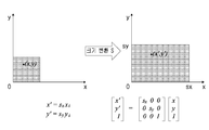
도 43은 본 발명에 따른 영상의 기하학적 변환의 일 예로서, 크기 변환을 설명하기 위한 도면이다.
도 44는 본 발명에 따른 영상의 기하학적 변환의 일 예로서, 회전 변환을 설명하기 위한 도면이다.
도 45는 본 발명에 따른 영상의 기하학적 변환의 일 예로서, 어파인 변환을 설명하기 위한 도면이다.
도 46은 본 발명에 따른 영상의 기하학적 변환의 일 예로서, 투영 변환을 설명하기 위한 도면이다.
도 47은 본 발명에 따라, 호모그래피를 구현하는 방법의 일 예를 설명하기 위한 도면이다.
도 48은 본 발명에 따른, 두 영상 내의 대응되는 두 지점간의 관계식을 산출하는 방법의 일 예이다.
도 49는 본 발명에 따라 기하 변환 행렬과 원본 영상에 기초하여 기하 변환 영상을 생성하는 방법을 설명하기 위한 도면이다.
도 50은 본 발명에 따른, 역사상을 이용하여 기하 변환 영상을 생성하는 방법을 설명하기 위한 도면이다.
도 51은 본 발명에 따른, 기하 변환 행렬과 원본 영상이 기초하여 기하 변환 영상을 생성하는 방법을 설명하기 위한 도면이다.
도 52는, 본 발명의 일 실시예에 따라, 도 51을 참조하여 설명된 다양한 보간법 중, 양선형 보간법을 설명하기 위한 도면이다.1 is a block diagram illustrating a configuration of an encoding apparatus to which the present invention is applied.
2 is a block diagram illustrating a configuration of a decoding apparatus to which the present invention is applied.
3 is a diagram schematically showing a division structure of an image when coding and decoding an image.
4 is a diagram for explaining an embodiment of an intra prediction process.
5 is a diagram for explaining an embodiment of an inter-picture prediction process.
FIG. 6 is a diagram for explaining a case where the degree of similarity between the current block and the unrecovered area is high.
7 is a view for explaining an intra prediction mode according to the present invention.
8 is a diagram for explaining the directionality of the intra prediction mode for an area including a directional pixel distribution.
9 is a diagram for explaining a method of constructing a reference pixel for intra-picture prediction of a current block using pixels of a current picture and a reference picture.
10 is a view for explaining the operation of an encoder for performing intra-picture prediction according to the present invention.
11 is a view for explaining the operation of the decoder for performing intra prediction in accordance with the present invention.
12 is a diagram for explaining Inter_DC prediction according to the present invention.
13 is a view for explaining an embodiment of Inter_DC prediction according to the present invention.
14 is a view for explaining an operation of an encoder that performs another embodiment of DC prediction according to the present invention.
15 is a diagram for explaining Inter_Planar prediction according to the present invention.
16 is a diagram showing another embodiment of a reference pixel that can be used for Inter_Planar prediction.
17 is a view for explaining another embodiment of Inter_Planar prediction according to the present invention.
18 is a view for explaining another embodiment of the forward prediction mode according to the present invention.
19 is a diagram for explaining directional prediction referring to a pixel in a similar area in a reference picture.
20 is a diagram for explaining another embodiment of the Inter_Angular prediction of the present invention.
21 is a view for explaining the operation of the decoder for performing the angular prediction according to the present invention.
22 is a diagram for explaining a filtering method using pixels in a similar area in a reference picture.
23 is a view for explaining an embodiment of an encoder that performs prediction using pixels in a similar area in a reference picture.
24 is a view for explaining another embodiment of an encoder that performs prediction using pixels in a similar area in a reference picture.
25 is a diagram for explaining an embodiment of a decoder for performing prediction using pixels in a similar area in a reference picture.
26 is a diagram for explaining another embodiment of a decoder for performing prediction using pixels in a similar area in a reference picture.
FIG. 27 illustrates an apparatus for performing Inter_DC prediction in a similar region pixel predicting unit according to an embodiment of the present invention. Referring to FIG.
28 is a diagram illustrating an apparatus for performing Inter_Planar prediction in a similar region pixel predicting unit according to an embodiment of the present invention.
29 is a diagram illustrating an apparatus for performing Inter_Angular prediction in a similar region pixel predicting unit according to an embodiment of the present invention.
30 is a diagram for explaining reference sample padding.
31 is a diagram for explaining reference sample filtering.
32 is a view for explaining a method of performing reference sample padding using a pixel of a reference picture when a reference pixel of intra prediction is not partially present.
FIG. 33 is a diagram for explaining a method of performing reference sample padding using pixels of a reference picture when all the reference pixels of intra-picture prediction are not present. FIG.
34 is a view for explaining an embodiment of reference sample padding according to the present invention.
35 is a diagram for explaining reference sample filtering using pixels of a reference picture.
36 is a diagram for explaining an embodiment of reference sample filtering according to the present invention.
37 is a view for explaining an embodiment of an encoder for performing inter-picture reference sample padding and / or inter-picture reference sample filtering according to the present invention.
FIG. 38 is a view for explaining another embodiment of an encoder for performing inter-picture reference sample padding and / or inter-picture reference sample filtering according to the present invention.
FIG. 39 is a diagram for explaining an embodiment of a decoder for performing inter-picture reference sample padding and / or inter-picture reference sample filtering according to the present invention.
FIG. 40 is a view for explaining another embodiment of a decoder for performing inter-picture reference sample padding and / or inter-picture reference sample filtering according to the present invention.
FIG. 41 is a diagram for explaining an embodiment of a detailed configuration of an inter-picture reference sample constructing unit according to the present invention.
FIG. 42 is a diagram for explaining motion transformation as an example of geometric transformation of an image according to the present invention.
43 is a diagram for explaining size conversion as an example of geometric transformation of an image according to the present invention.
FIG. 44 is a diagram for explaining rotation transformation, as an example of geometric transformation of an image according to the present invention.
45 is a diagram for explaining affine transformation as an example of geometric transformation of an image according to the present invention.
46 is a diagram for explaining projection transformation as an example of geometric transformation of an image according to the present invention.
47 is a diagram for explaining an example of a method of implementing homography according to the present invention.
48 is an example of a method of calculating a relational expression between two corresponding points in two images according to the present invention.
49 is a diagram for explaining a method of generating a geometric transformation image based on a geometric transformation matrix and an original image according to the present invention.
FIG. 50 is a diagram for explaining a method of generating a geometric transformation image using the history according to the present invention.
51 is a view for explaining a method of generating a geometric transformation image based on a geometric transformation matrix and an original image according to the present invention.
Fig. 52 is a diagram for explaining a bilinear interpolation method among the various interpolation methods explained with reference to Fig. 51 according to an embodiment of the present invention.
본 발명은 다양한 변경을 가할 수 있고 여러 가지 실시예를 가질 수 있는 바, 특정 실시예들을 도면에 예시하고 상세한 설명에 상세하게 설명하고자 한다. 그러나, 이는 본 발명을 특정한 실시 형태에 대해 한정하려는 것이 아니며, 본 발명의 사상 및 기술 범위에 포함되는 모든 변경, 균등물 내지 대체물을 포함하는 것으로 이해되어야 한다. 도면에서 유사한 참조부호는 여러 측면에 걸쳐서 동일하거나 유사한 기능을 지칭한다. 도면에서의 요소들의 형상 및 크기 등은 보다 명확한 설명을 위해 과장될 수 있다. 후술하는 예시적 실시예들에 대한 상세한 설명은, 특정 실시예를 예시로서 도시하는 첨부 도면을 참조한다. 이들 실시예는 당업자가 실시예를 실시할 수 있기에 충분하도록 상세히 설명된다. 다양한 실시예들은 서로 다르지만 상호 배타적일 필요는 없음이 이해되어야 한다. 예를 들어, 여기에 기재되어 있는 특정 형상, 구조 및 특성은 일 실시예에 관련하여 본 발명의 정신 및 범위를 벗어나지 않으면서 다른 실시예로 구현될 수 있다. 또한, 각각의 개시된 실시예 내의 개별 구성요소의 위치 또는 배치는 실시예의 정신 및 범위를 벗어나지 않으면서 변경될 수 있음이 이해되어야 한다. 따라서, 후술하는 상세한 설명은 한정적인 의미로서 취하려는 것이 아니며, 예시적 실시예들의 범위는, 적절하게 설명된다면, 그 청구항들이 주장하는 것과 균등한 모든 범위와 더불어 첨부된 청구항에 의해서만 한정된다.While the invention is susceptible to various modifications and alternative forms, specific embodiments thereof are shown by way of example in the drawings and will herein be described in detail. It should be understood, however, that the invention is not intended to be limited to the particular embodiments, but includes all modifications, equivalents, and alternatives falling within the spirit and scope of the invention. In the drawings, like reference numerals refer to the same or similar functions throughout the several views. The shape and size of the elements in the figures may be exaggerated for clarity. The following detailed description of exemplary embodiments refers to the accompanying drawings, which illustrate, by way of illustration, specific embodiments. These embodiments are described in sufficient detail to enable those skilled in the art to practice the embodiments. It should be understood that the various embodiments are different, but need not be mutually exclusive. For example, certain features, structures, and characteristics described herein may be implemented in other embodiments without departing from the spirit and scope of the invention in connection with an embodiment. It is also to be understood that the location or arrangement of the individual components within each disclosed embodiment may be varied without departing from the spirit and scope of the embodiments. The following detailed description is, therefore, not to be taken in a limiting sense, and the scope of the exemplary embodiments is to be limited only by the appended claims, along with the full scope of equivalents to which such claims are entitled, if properly explained.
본 발명에서 제1, 제2 등의 용어는 다양한 구성요소들을 설명하는데 사용될 수 있지만, 상기 구성요소들은 상기 용어들에 의해 한정되어서는 안 된다. 상기 용어들은 하나의 구성요소를 다른 구성요소로부터 구별하는 목적으로만 사용된다. 예를 들어, 본 발명의 권리 범위를 벗어나지 않으면서 제1 구성요소는 제2 구성요소로 명명될 수 있고, 유사하게 제2 구성요소도 제1 구성요소로 명명될 수 있다. 및/또는 이라는 용어는 복수의 관련된 기재된 항목들의 조합 또는 복수의 관련된 기재된 항목들 중의 어느 항목을 포함한다.The terms first, second, etc. in the present invention may be used to describe various components, but the components should not be limited by the terms. The terms are used only for the purpose of distinguishing one component from another. For example, without departing from the scope of the present invention, the first component may be referred to as a second component, and similarly, the second component may also be referred to as a first component. And / or < / RTI > includes any combination of a plurality of related listed items or any of a plurality of related listed items.
본 발명의 어떤 구성 요소가 다른 구성 요소에 "연결되어" 있다거나 "접속되어" 있다고 언급된 때에는, 그 다른 구성 요소에 직접적으로 연결되어 있거나 또는 접속되어 있을 수도 있으나, 중간에 다른 구성 요소가 존재할 수도 있다고 이해되어야 할 것이다. 반면에, 어떤 구성요소가 다른 구성요소에 "직접 연결되어"있다거나 "직접 접속되어"있다고 언급된 때에는, 중간에 다른 구성요소가 존재하지 않는 것으로 이해되어야 할 것이다.Whenever an element of the invention is referred to as being "connected" or "connected" to another element, it may be directly connected or connected to the other element, but other elements may be present in between It should be understood. On the other hand, when an element is referred to as being "directly connected" or "directly connected" to another element, it should be understood that there are no other elements in between.
본 발명의 실시예에 나타나는 구성부들은 서로 다른 특징적인 기능들을 나타내기 위해 독립적으로 도시되는 것으로, 각 구성부들이 분리된 하드웨어나 하나의 소프트웨어 구성단위로 이루어짐을 의미하지 않는다. 즉, 각 구성부는 설명의 편의상 각각의 구성부로 나열하여 포함한 것으로 각 구성부 중 적어도 두 개의 구성부가 합쳐져 하나의 구성부로 이루어지거나, 하나의 구성부가 복수 개의 구성부로 나뉘어져 기능을 수행할 수 있고 이러한 각 구성부의 통합된 실시예 및 분리된 실시예도 본 발명의 본질에서 벗어나지 않는 한 본 발명의 권리범위에 포함된다.The components shown in the embodiments of the present invention are shown separately to represent different characteristic functions and do not mean that each component is composed of separate hardware or software constituent units. That is, each constituent unit is included in each constituent unit for convenience of explanation, and at least two constituent units of the constituent units may be combined to form one constituent unit, or one constituent unit may be divided into a plurality of constituent units to perform a function. The integrated embodiments and separate embodiments of the components are also included within the scope of the present invention, unless they depart from the essence of the present invention.
본 발명에서 사용한 용어는 단지 특정한 실시예를 설명하기 위해 사용된 것으로, 본 발명을 한정하려는 의도가 아니다. 단수의 표현은 문맥상 명백하게 다르게 뜻하지 않는 한, 복수의 표현을 포함한다. 본 발명에서, "포함하다" 또는 "가지다" 등의 용어는 명세서상에 기재된 특징, 숫자, 단계, 동작, 구성요소, 부품 또는 이들을 조합한 것이 존재함을 지정하려는 것이지, 하나 또는 그 이상의 다른 특징들이나 숫자, 단계, 동작, 구성요소, 부품 또는 이들을 조합한 것들의 존재 또는 부가 가능성을 미리 배제하지 않는 것으로 이해되어야 한다. 즉, 본 발명에서 특정 구성을 "포함"한다고 기술하는 내용은 해당 구성 이외의 구성을 배제하는 것이 아니며, 추가적인 구성이 본 발명의 실시 또는 본 발명의 기술적 사상의 범위에 포함될 수 있음을 의미한다. The terminology used herein is for the purpose of describing particular embodiments only and is not intended to be limiting of the invention. The singular expressions include plural expressions unless the context clearly dictates otherwise. In the present invention, the term " comprises " or " having ", etc. is intended to specify that there is a feature, number, step, operation, element, But do not preclude the presence or addition of one or more other features, integers, steps, operations, elements, components, or combinations thereof. In other words, the description of "including" a specific configuration in the present invention does not exclude a configuration other than the configuration, and means that additional configurations can be included in the practice of the present invention or the technical scope of the present invention.
본 발명의 일부의 구성 요소는 본 발명에서 본질적인 기능을 수행하는 필수적인 구성 요소는 아니고 단지 성능을 향상시키기 위한 선택적 구성 요소일 수 있다. 본 발명은 단지 성능 향상을 위해 사용되는 구성 요소를 제외한 본 발명의 본질을 구현하는데 필수적인 구성부만을 포함하여 구현될 수 있고, 단지 성능 향상을 위해 사용되는 선택적 구성 요소를 제외한 필수 구성 요소만을 포함한 구조도 본 발명의 권리범위에 포함된다.Some of the elements of the present invention are not essential elements that perform essential functions in the present invention, but may be optional elements only for improving performance. The present invention can be implemented only with components essential for realizing the essence of the present invention, except for the components used for the performance improvement, and can be implemented by only including the essential components except the optional components used for performance improvement Are also included in the scope of the present invention.
이하, 도면을 참조하여 본 발명의 실시 형태에 대하여 구체적으로 설명한다. 본 명세서의 실시예를 설명함에 있어, 관련된 공지 구성 또는 기능에 대한 구체적인 설명이 본 명세서의 요지를 흐릴 수 있다고 판단되는 경우에는 그 상세한 설명은 생략하고, 도면상의 동일한 구성요소에 대해서는 동일한 참조부호를 사용하고 동일한 구성요소에 대해서 중복된 설명은 생략한다.Hereinafter, embodiments of the present invention will be described in detail with reference to the drawings. In the following description of the embodiments of the present invention, a detailed description of known functions and configurations incorporated herein has been omitted for the sake of clarity and conciseness. And redundant descriptions are omitted for the same components.
또한, 이하에서 영상은 동영상(video)을 구성하는 하나의 픽처(picture)를 의미할 수 있으며, 동영상 자체를 나타낼 수도 있다. 예를 들면, "영상의 부호화 및/또는 복호화"는 "비디오의 부호화 및/또는 복호화"를 의미할 수 있으며, "비디오를 구성하는 영상들 중 하나의 영상의 부호화 및/또는 복호화"를 의미할 수도 있다. 여기서, 픽처는 영상과 동일한 의미를 가질 수 있다.Hereinafter, an image may refer to a picture constituting a video, or may represent a moving image itself. For example, " encoding and / or decoding of an image " may mean " encoding and / or decoding of video ", which means " encoding and / or decoding of one of the images constituting a video " It is possible. Here, the picture may have the same meaning as the picture.
용어 설명Term Description
부호화기(Encoder): 부호화(Encoding)를 수행하는 장치를 의미한다.Encoder: An apparatus that performs encoding.
복호화기(Decoder): 복호화(Decoding)를 수행하는 장치를 의미한다.Decoder: An apparatus that performs decoding.
블록(Block): 샘플(Sample)의 MxN 배열이다. 여기서 M과 N은 양의 정수 값을 의미하며, 블록은 흔히 2차원 형태의 샘플 배열을 의미할 수 있다. 블록은 유닛을 의미할 수 있다. 현재 블록은 부호화 시 부호화의 대상이 되는 부호화 대상 블록, 복호화 시 복호화의 대상이 되는 복호화 대상 블록을 의미할 수 있다. 또한, 현재 블록은 부호화 블록, 예측 블록, 잔여 블록, 변환 블록 중 적어도 하나일 수 있다.Block: An MxN array of samples. Here, M and N mean positive integer values, and blocks can often refer to a two-dimensional sample array. A block may mean a unit. The current block may be a current block to be encoded at the time of encoding or a current block to be decoded at the time of decoding. Also, the current block may be at least one of a coding block, a prediction block, a residual block, and a transform block.
샘플(Sample): 블록을 구성하는 기본 단위이다. 비트 깊이 (bit depth, Bd)에 따라 0부터 2Bd - 1까지의 값으로 표현될 수 있다. 본 발명에서 샘플은 화소 또는 픽셀과 같은 의미로 사용될 수 있다. Sample: It is the basic unit that constitutes a block. It can be expressed as a value from 0 to 2 Bd - 1 according to the bit depth (B d ). In the present invention, a sample may be used in the same sense as a pixel or a pixel.
유닛(Unit): 영상 부호화 및 복호화의 단위를 의미한다. 영상의 부호화 및 복호화에 있어서, 유닛은 하나의 영상을 분할한 영역일 수 있다. 또한, 유닛은 하나의 영상을 세분화 된 유닛으로 분할하여 부호화 혹은 복호화 할 때 그 분할된 단위를 의미할 수 있다. 영상의 부호화 및 복호화에 있어서, 유닛 별로 기정의된 처리가 수행될 수 있다. 하나의 유닛은 유닛에 비해 더 작은 크기를 갖는 하위 유닛으로 더 분할될 수 있다. 기능에 따라서, 유닛은 블록(Block), 매크로블록(Macroblock), 부호화 트리 유닛(Coding Tree Unit), 부호화 트리 블록(Coding Tree Block), 부호화 유닛(Coding Unit), 부호화 블록(Coding Block), 예측 유닛(Prediction Unit), 예측 블록(Prediction Block), 잔여 유닛(Residual Unit), 잔여 블록(Residual Block), 변환 유닛(Transform Unit), 변환 블록(Transform Block) 등을 의미할 수 있다. 또한, 유닛은 블록과 구분하여 지칭하기 위해 휘도(Luma) 성분 블록과 그에 대응하는 색차(Chroma) 성분 블록 그리고 각 블록에 대한 구문 요소를 포함한 것을 의미할 수 있다. 유닛은 다양한 크기와 형태를 가질 수 있으며, 특히 유닛의 형태는 직사각형뿐만 아니라 정사각형, 사다리꼴, 삼각형, 오각형 등 2차원으로 표현될 수 있는 기하학적 도형을 포함할 수 있다. 또한, 유닛 정보는 부호화 유닛, 예측 유닛, 잔여 유닛, 변환 유닛 등을 가리키는 유닛의 타입, 유닛의 크기, 유닛의 깊이, 유닛의 부호화 및 복호화 순서 등 중 적어도 하나 이상을 포함할 수 있다.Unit: Unit of image encoding and decoding. In coding and decoding of an image, a unit may be an area obtained by dividing one image. In addition, a unit may mean a divided unit when an image is divided into subdivided units and then encoded or decoded. In the encoding and decoding of images, predetermined processing can be performed for each unit. One unit may be further subdivided into smaller units having a smaller size than the unit. Depending on the function, the unit may be a block, a macroblock, a coding tree unit, a coding tree block, a coding unit, a coding block, A Prediction Unit, a Prediction Block, a Residual Unit, a Residual Block, a Transform Unit, a Transform Block, and the like. The unit may also include a Luma component block, a corresponding chroma component block, and a syntax element for each block in order to be distinguished from the block. The unit may have various sizes and shapes, and in particular, the shape of the unit may include not only rectangles but also geometric figures that can be expressed in two dimensions, such as square, trapezoid, triangle, pentagon. The unit information may include at least one of a unit type indicating a coding unit, a prediction unit, a residual unit, a conversion unit, etc., a unit size, a unit depth, a unit encoding and decoding order,
부호화 트리 유닛(Coding Tree Unit): 하나의 휘도 성분(Y) 부호화 트리 블록과 관련된 두 색차 성분(Cb, Cr) 부호화 트리 블록들로 구성된다. 또한, 상기 블록들과 각 블록에 대한 구문 요소를 포함한 것을 의미할 수도 있다. 각 부호화 트리 유닛은 부호화 유닛, 예측 유닛, 변환 유닛 등의 하위 유닛을 구성하기 위하여 쿼드트리(quad tree), 이진트리(binary tree) 등 하나 이상의 분할 방식을 이용하여 분할될 수 있다. 입력 영상의 분할처럼 영상의 복/부호화 과정에서 처리 단위가 되는 픽셀 블록을 지칭하기 위한 용어로 사용될 수 있다. Coding Tree Unit: It is composed of two chrominance component (Cb, Cr) coded tree blocks related to one luminance component (Y) coded tree block. It may also include the blocks and the syntax elements for each block. Each coding tree unit may be divided using one or more division methods such as a quad tree, a binary tree, etc. to form a lower unit such as a coding unit, a prediction unit, a conversion unit, and the like. It can be used as a term to refer to a pixel block which is a processing unit in the process of image encoding / decoding like an input image.
부호화 트리 블록(Coding Tree Block): Y 부호화 트리 블록, Cb 부호화 트리 블록, Cr 부호화 트리 블록 중 어느 하나를 지칭하기 위한 용어로 사용될 수 있다.Coding Tree Block: It can be used as a term for designating any one of a Y encoded tree block, a Cb encoded tree block, and a Cr encoded tree block.
주변 블록(Neighbor block): 현재 블록에 인접한 블록을 의미한다. 현재 블록에 인접한 블록은 현재 블록에 경계가 맞닿은 블록 또는 현재 블록으로부터 소정의 거리 내에 위치한 블록을 의미할 수 있다. 주변 블록은 현재 블록의 꼭지점에 인접한 블록을 의미할 수 있다. 여기에서, 현재 블록의 꼭지점에 인접한 블록이란, 현재 블록에 가로로 인접한 이웃 블록에 세로로 인접한 블록 또는 현재 블록에 세로로 인접한 이웃 블록에 가로로 인접한 블록일 수 있다. 주변 블록은 복원된 주변 블록을 의미할 수도 있다.Neighbor block: A block adjacent to the current block. A block adjacent to the current block may refer to a block that is bordered by the current block or a block located within a predetermined distance from the current block. The neighboring block may mean a block adjacent to the vertex of the current block. Here, a block adjacent to the vertex of the current block may be a block vertically adjacent to a neighboring block that is adjacent to the current block, or a block that is laterally adjacent to a neighboring block vertically adjacent to the current block. A neighboring block may mean a restored neighboring block.
복원된 주변 블록(Reconstructed Neighbor Block): 현재 블록 주변에 공간적(Spatial)/시간적(Temporal)으로 이미 부호화 혹은 복호화된 주변 블록을 의미한다. 이때, 복원된 주변 블록은 복원된 주변 유닛을 의미할 수 있다. 복원된 공간적 주변 블록은 현재 픽처 내의 블록이면서 부호화 및/또는 복호화를 통해 이미 복원된 블록일 수 있다. 복원된 시간적 주변 블록은 참조 픽처 내에서 현재 픽처의 현재 블록과 동일한 위치의 복원된 블록 또는 그 주변 블록일 수 있다.Reconstructed Neighbor Block: A neighboring block that has already been encoded or decoded in a spatial / temporal manner around the current block. At this time, the restored neighboring block may mean the restored neighboring unit. The reconstructed spatial neighboring block may be a block already in the current picture and reconstructed through encoding and / or decoding. The reconstructed temporal neighboring block may be a reconstructed block or a neighboring block in the reference picture at the same position as the current block of the current picture.
유닛 깊이(Depth): 유닛이 분할된 정도를 의미한다. 트리 구조(Tree Structure)에서 루트 노드(Root Node)는 깊이가 가장 얕고, 리프 노드(Leaf Node)는 깊이가 가장 깊다고 할 수 있다. 또한, 유닛을 트리 구조로 표현했을 때 유닛이 존재하는 레벨(Level)이 유닛 깊이를 의미할 수 있다.Unit Depth: The degree to which the unit is divided. In the tree structure, the root node has the shallower depth and the leaf node has the deepest depth. Also, when a unit is represented by a tree structure, the level at which the unit exists (Level) may mean unit depth.
비트스트림(Bitstream): 부호화된 영상 정보를 포함하는 비트의 열을 의미한다. Bitstream: A bit stream containing encoded image information.
파라미터 세트(Parameter Set): 비트스트림 내의 구조 중 헤더 정보에 해당한다. 비디오 파라미터 세트(video parameter set), 시퀀스 파라미터 세트(sequence parameter set), 픽처 파라미터 세트(picture parameter set), 적응 파라미터 세트(adaptation parameter set) 중 적어도 하나가 파라미터 세트에 포함될 수 있다. 또한, 파라미터 세트는 슬라이스(slice) 헤더 및 타일(tile) 헤더 정보를 포함할 수도 있다.Parameter Set: corresponds to the header information in the structure in the bitstream. At least one of a video parameter set, a sequence parameter set, a picture parameter set and an adaptation parameter set may be included in the parameter set. The set of parameters may also include a slice header and tile header information.
파싱(Parsing): 비트스트림을 엔트로피 복호화하여 구문 요소(Syntax Element)의 값을 결정하는 것을 의미하거나, 엔트로피 복호화 자체를 의미할 수 있다.Parsing: means to determine the value of a syntax element by entropy decoding the bitstream, or it may mean entropy decoding itself.
심볼(Symbol): 부호화/복호화 대상 유닛의 구문 요소, 부호화 파라미터(coding parameter), 변환 계수(Transform Coefficient)의 값 등 중 적어도 하나를 의미할 수 있다. 또한, 심볼은 엔트로피 부호화의 대상 혹은 엔트로피 복호화의 결과를 의미할 수 있다.Symbol: It can mean at least one of a syntax element of a unit to be encoded / decoded, a coding parameter, a value of a transform coefficient, and the like. In addition, the symbol may mean a target of entropy encoding or a result of entropy decoding.
예측 유닛(Prediction Unit): 화면 간 예측, 화면 내 예측, 화면 간 보상, 화면 내 보상, 움직임 보상 등 예측을 수행할 때의 기본 유닛을 의미한다. 하나의 예측 유닛은 크기가 작은 복수의 파티션(Partition) 또는 하위 예측 유닛으로 분할 될 수도 있다. Prediction Unit: A basic unit for performing prediction such as inter-picture prediction, intra-picture prediction, inter-picture compensation, in-picture compensation, and motion compensation. One prediction unit may be divided into a plurality of smaller partitions or a lower prediction unit.
예측 유닛 파티션(Prediction Unit Partition): 예측 유닛이 분할된 형태를 의미한다.Prediction Unit Partition: means a type in which a prediction unit is divided.
참조 영상 리스트(Reference Picture List): 화면 간 예측 혹은 움직임 보상에 사용되는 하나 이상의 참조 영상이 포함된 리스트를 의미한다. 참조 영상 리스트의 종류는 LC (List Combined), L0 (List 0), L1 (List 1), L2 (List 2), L3 (List 3) 등이 있을 수 있으며, 화면 간 예측에는 1개 이상의 참조 영상 리스트가 사용될 수 있다.Reference Picture List: A list containing one or more reference pictures used for inter-picture prediction or motion compensation. The types of the reference image list may be LC (List Combined), L0 (List 0), L1 (List 1), L2 (List 2), L3 (List 3) A list can be used.
화면 간 예측 지시자(Inter Prediction Indicator): 현재 블록의 화면 간 예측 방향(단방향 예측, 쌍방향 예측 등)을 의미할 수 있다. 또는, 현재 블록의 예측 블록을 생성할 때 사용되는 참조 영상의 개수를 의미할 수 있다. 또는, 현재 블록에 대해 화면 간 예측 혹은 움직임 보상을 수행할 때 사용되는 예측 블록의 개수를 의미할 수 있다.Inter-Prediction Indicator: It can mean inter-picture prediction direction (unidirectional prediction, bidirectional prediction, etc.) of the current block. Or the number of reference images used in generating a prediction block of the current block. Or the number of prediction blocks used when inter-picture prediction or motion compensation is performed on the current block.
참조 영상 색인(Reference Picture Index): 참조 영상 리스트에서 특정 참조 영상을 지시하는 색인을 의미한다.Reference Picture Index: Indicates an index indicating a specific reference image in the reference image list.
참조 영상(Reference Picture): 화면 간 예측 혹은 움직임 보상을 위해서 특정 블록이 참조하는 영상을 의미할 수 있다.Reference Picture: Reference picture refers to an image referred to by a specific block for inter-picture prediction or motion compensation.
움직임 벡터(Motion Vector): 화면 간 예측 혹은 움직임 보상에 사용되는 2차원 벡터이며, 부호화/복호화 대상 영상과 참조 영상 사이의 오프셋을 의미할 수 있다. 예를 들어, (mvX, mvY)는 움직임 벡터를 나타낼 수 있으며, mvX는 가로(horizontal) 성분, mvY는 세로(vertical) 성분을 나타낼 수 있다.Motion Vector: This is a two-dimensional vector used for inter-picture prediction or motion compensation, and may mean an offset between a video to be encoded / decoded and a reference video. For example, (mvX, mvY) may represent a motion vector, mvX may represent a horizontal component, and mvY may represent a vertical component.
움직임 벡터 후보(Motion Vector Candidate): 움직임 벡터를 예측할 때 예측 후보가 되는 블록 혹은 그 블록의 움직임 벡터를 의미한다. 또한, 움직임 벡터 후보는 움직임 벡터 후보 리스트에 포함될 수 있다.Motion Vector Candidate (Motion Vector Candidate): A block that is a candidate for prediction when a motion vector is predicted, or a motion vector of the block. In addition, the motion vector candidate may be included in the motion vector candidate list.
움직임 벡터 후보 리스트(Motion Vector Candidate List): 움직임 벡터 후보를 이용하여 구성된 리스트를 의미할 수 있다.Motion Vector Candidate List: It can mean a list constructed using motion vector candidates.
움직임 벡터 후보 색인(Motion Vector Candidate Index): 움직임 벡터 후보 리스트 내의 움직임 벡터 후보를 가리키는 지시자를 의미한다. 움직임 벡터 예측기(Motion Vector Predictor)의 색인(index)이라고도 할 수 있다.Motion Vector Candidate Index: An indicator indicating a motion vector candidate in a motion vector candidate list. It may be referred to as an index of a motion vector predictor.
움직임 정보(Motion Information): 움직임 벡터, 참조 영상 색인, 화면 간 예측 지시자(Inter Prediction Indicator) 뿐만 아니라 참조 영상 리스트 정보, 참조 영상, 움직임 벡터 후보, 움직임 벡터 후보 색인, 머지 후보, 머지 색인 등 중 적어도 하나를 포함하는 정보를 의미할 수 있다.Motion Information: At least one of motion vector, reference picture index, inter prediction indicator, reference picture list information, reference picture, motion vector candidate, motion vector candidate index, merge candidate, merge index, Can mean information including one.
머지 후보 리스트(Merge Candidate List): 머지 후보를 이용하여 구성된 리스트를 의미한다.Merge Candidate List: A list consisting of merge candidates.
머지 후보(Merge Candidate): 공간적 머지 후보, 시간적 머지 후보, 조합된 머지 후보, 조합 양예측 머지 후보, 제로 머지 후보 등을 의미한다. 머지 후보는 화면 간 예측 지시자, 각 리스트에 대한 참조 영상 색인, 움직임 벡터 등의 움직임 정보를 포함할 수 있다.Merge Candidate: A spatial merge candidate, a temporal merge candidate, a combined merge candidate, a combined merge candidate merge candidate, and a zero merge candidate. The merge candidate may include motion information such as an inter-picture prediction indicator, a reference picture index for each list, and a motion vector.
머지 색인(Merge Index): 머지 후보 리스트 내 머지 후보를 지시하는 정보를 의미한다. 또한, 머지 색인은 공간적/시간적으로 현재 블록과 인접하게 복원된 블록들 중 머지 후보를 유도한 블록을 지시할 수 있다. 또한, 머지 색인은 머지 후보가 가지는 움직임 정보 중 적어도 하나를 지시할 수 있다.Merge Index: This information indicates the merge candidate in the merge candidate list. Also, the merge index may indicate a block from which the merge candidate is derived, among the restored blocks spatially / temporally adjacent to the current block. Further, the merge index may indicate at least one of the motion information of the merge candidate.
변환 유닛(Transform Unit): 변환, 역변환, 양자화, 역양자화, 변환 계수 부호화/복호화와 같이 잔여 신호(residual signal) 부호화/복호화를 수행할 때의 기본 유닛을 의미한다. 하나의 변환 유닛은 분할되어 크기가 작은 복수의 변환 유닛으로 분할될 수 있다. Transform Unit: Refers to a basic unit when performing residual signal encoding / decoding such as transform, inverse transform, quantization, inverse quantization, and transform coefficient encoding / decoding. One conversion unit can be divided and divided into a plurality of conversion units having a small size.
스케일링(Scaling): 변환 계수 레벨에 인수를 곱하는 과정을 의미한다. 변환 계수 레벨에 대한 스케일링의 결과로 변환 계수를 생성할 수 있다. 스케일링을 역양자화(dequantization)라고도 부를 수 있다.Scaling: The process of multiplying the factor of the transform coefficient by an argument. A transform coefficient may be generated as a result of scaling to a transform coefficient level. Scaling can also be referred to as dequantization.
양자화 매개변수(Quantization Parameter): 양자화에서 변환 계수에 대해 변환 계수 레벨(transform coefficient level)을 생성할 때 사용하는 값을 의미할 수 있다. 또는, 역양자화에서 변환 계수 레벨을 스케일링(scaling)하여 변환 계수를 생성할 때 사용하는 값을 의미할 수도 있다. 양자화 매개변수는 양자화 스텝 크기(step size)에 매핑된 값일 수 있다.Quantization Parameter: This value can be used to generate a transform coefficient level for a transform coefficient in a quantization. Alternatively, it may mean a value used in generating a transform coefficient by scaling a transform coefficient level in the inverse quantization. The quantization parameter may be a value mapped to a quantization step size.
잔여 양자화 매개변수(Delta Quantization Parameter): 예측된 양자화 매개변수와 부호화/복호화 대상 유닛의 양자화 매개변수의 차분된 값을 의미한다.Residual Quantization Parameter (Delta Quantization Parameter): means a difference value between a predicted quantization parameter and a quantization parameter of a unit to be encoded / decoded.
스캔(Scan): 블록 혹은 행렬 내 계수의 순서를 정렬하는 방법을 의미한다. 예를 들어, 2차원 배열을 1차원 배열 형태로 정렬하는 것을 스캔이라고 한다. 또는, 1차원 배열을 2차원 배열 형태로 정렬하는 것도 스캔 혹은 역 스캔(Inverse Scan)이라고 부를 수 있다.Scan: means a method of arranging the order of blocks or coefficients in a matrix. For example, arranging a two-dimensional array in a one-dimensional array is called a scan. Alternatively, arranging the one-dimensional arrays in the form of a two-dimensional array may be called scanning or inverse scanning.
변환 계수(Transform Coefficient): 부호화기에서 변환을 수행하고 나서 생성된 계수 값을 의미한다. 또는, 복호화기에서 엔트로피 복호화 및 역양자화 중 적어도 하나를 수행하고 나서 생성된 계수 값을 의미할 수도 있다.변환 계수 또는 잔여 신호에 양자화를 적용한 양자화된 레벨 또는 양자화된 변환 계수 레벨도 변환 계수의 의미에 포함될 수 있다.Transform Coefficient: It means the coefficient value generated after the conversion in the encoder. Alternatively, it may mean a coefficient value generated after at least one of entropy decoding and inverse quantization is performed in the decoder. Quantized level or quantized transform coefficient level obtained by applying quantization to a transform coefficient or residual signal. .
양자화된 레벨(Quantized Level): 부호화기에서 변환 계수 또는 잔여 신호에 양자화를 수행하여 생성된 값을 의미한다. 또는, 복호화기에서 역양자화를 수행하기 전 역양자화의 대상이 되는 값을 의미할 수도 있다. 유사하게, 변환 및 양자화의 결과인 양자화된 변환 계수 레벨도 양자화된 레벨의 의미에 포함될 수 있다.Quantized Level (Quantized Level): means a value generated by performing quantization on a transform coefficient or residual signal in an encoder. Alternatively, it may mean a value to be subjected to inverse quantization before performing inverse quantization in the decoder. Similarly, quantized transform coefficient levels that are the result of transform and quantization can also be included in the meaning of the quantized levels.
넌제로 변환 계수(Non-zero Transform Coefficient): 값의 크기가 0이 아닌 변환 계수 혹은 값의 크기가 0이 아닌 변환 계수 레벨을 의미한다.Non-zero Transform Coefficient: A non-zero transform coefficient or a non-zero transform coefficient level.
양자화 행렬(Quantization Matrix): 영상의 주관적 화질 혹은 객관적 화질을 향상시키기 위해서 양자화 혹은 역양자화 과정에서 이용하는 행렬을 의미한다. 양자화 행렬을 스케일링 리스트(scaling list)라고도 부를 수 있다.Quantization Matrix: A matrix used in the quantization or inverse quantization process to improve the subjective or objective image quality of an image. The quantization matrix may also be referred to as a scaling list.
양자화 행렬 계수(Quantization Matrix Coefficient): 양자화 행렬 내의 각 원소(element)를 의미한다. 양자화 행렬 계수를 행렬 계수(matrix coefficient)라고도 할 수 있다.Quantization Matrix Coefficient: means each element in the quantization matrix. The quantization matrix coefficient may be referred to as a matrix coefficient.
기본 행렬(Default Matrix): 부호화기와 복호화기에서 미리 정의되어 있는 소정의 양자화 행렬을 의미한다.Default Matrix: A predetermined quantization matrix predefined by the encoder and decoder.
비 기본 행렬(Non-default Matrix): 부호화기와 복호화기에서 미리 정의되지 않고, 사용자에 의해서 시그널링되는 양자화 행렬을 의미한다.Non-default Matrix: A quantization matrix that is not predefined in the encoder and decoder but is signaled by the user.
도 1은 본 발명이 적용되는 부호화 장치의 일 실시예에 따른 구성을 나타내는 블록도이다.1 is a block diagram illustrating a configuration of an encoding apparatus to which the present invention is applied.
부호화 장치(100)는 인코더, 비디오 부호화 장치 또는 영상 부호화 장치일 수 있다. 비디오는 하나 이상의 영상들을 포함할 수 있다. 부호화 장치(100)는 하나 이상의 영상들을 순차적으로 부호화할 수 있다.The
도 1을 참조하면, 부호화 장치(100)는 움직임 예측부(111), 움직임 보상부(112), 인트라 예측부(120), 스위치(115), 감산기(125), 변환부(130), 양자화부(140), 엔트로피 부호화부(150), 역양자화부(160), 역변환부(170), 가산기(175), 필터부(180) 및 참조 픽처 버퍼(190)를 포함할 수 있다.1, an
부호화 장치(100)는 입력 영상에 대해 인트라 모드 및/또는 인터 모드로 부호화를 수행할 수 있다. 또한, 부호화 장치(100)는 입력 영상에 대한 부호화를 통해 비트스트림을 생성할 수 있고, 생성된 비트스트림을 출력할 수 있다. 생성된 비트스트림은 컴퓨터 판독가능한 기록 매체에 저장되거나, 유/무선 전송 매체를 통해 스트리밍될 수 있다. 예측 모드로 인트라 모드가 사용되는 경우 스위치(115)는 인트라로 전환될 수 있고, 예측 모드로 인터 모드가 사용되는 경우 스위치(115)는 인터로 전환될 수 있다. 여기서 인트라 모드는 화면 내 예측 모드를 의미할 수 있으며, 인터 모드는 화면 간 예측 모드를 의미할 수 있다. 부호화 장치(100)는 입력 영상의 입력 블록에 대한 예측 블록을 생성할 수 있다. 또한, 부호화 장치(100)는 예측 블록이 생성된 후, 입력 블록 및 예측 블록의 차분(residual)을 부호화할 수 있다. 입력 영상은 현재 부호화의 대상인 현재 영상으로 칭해질 수 있다. 입력 블록은 현재 부호화의 대상인 현재 블록 혹은 부호화 대상 블록으로 칭해질 수 있다.The
예측 모드가 인트라 모드인 경우, 인트라 예측부(120)는 현재 블록의 주변에 이미 부호화/복호화된 블록의 픽셀 값을 참조 화소로서 이용할 수 있다. 인트라 예측부(120)는 참조 화소를 이용하여 공간적 예측을 수행할 수 있고, 공간적 예측을 통해 입력 블록에 대한 예측 샘플들을 생성할 수 있다. 여기서 인트라 예측은 화면 내 예측을 의미할 수 있다.When the prediction mode is the intra mode, the
예측 모드가 인터 모드인 경우, 움직임 예측부(111)는, 움직임 예측 과정에서 참조 영상으로부터 입력 블록과 가장 매치가 잘 되는 영역을 검색할 수 있고, 검색된 영역을 이용하여 움직임 벡터를 도출할 수 있다. 참조 영상은 참조 픽처 버퍼(190)에 저장될 수 있다.When the prediction mode is the inter mode, the
움직임 보상부(112)는 움직임 벡터를 이용하는 움직임 보상을 수행함으로써 예측 블록을 생성할 수 있다. 여기서 인터 예측은 화면 간 예측 혹은 움직임 보상을 의미할 수 있다.The
상기 움직임 예측부(111)과 움직임 보상부(112)는 움직임 벡터의 값이 정수 값을 가지지 않을 경우에 참조 영상 내의 일부 영역에 대해 보간 필터(Interpolation Filter)를 적용하여 예측 블록을 생성할 수 있다. 화면 간 예측 혹은 움직임 보상을 수행하기 위해 부호화 유닛을 기준으로 해당 부호화 유닛에 포함된 예측 유닛의 움직임 예측 및 움직임 보상 방법이 스킵 모드(Skip Mode), 머지 모드(Merge Mode), 향상된 움직임 벡터 예측(Advanced Motion Vector Prediction; AMVP) 모드, 현재 픽처 참조 모드 중 어떠한 방법인지 여부를 판단할 수 있고, 각 모드에 따라 화면 간 예측 혹은 움직임 보상을 수행할 수 있다.The
감산기(125)는 입력 블록 및 예측 블록의 차분을 사용하여 잔여 블록(residual block)을 생성할 수 있다. 잔여 블록은 잔여 신호로 칭해질 수도 있다. 잔여 신호는 원 신호 및 예측 신호 간의 차이(difference)를 의미할 수 있다. 또는, 잔여 신호는 원신호 및 예측 신호 간의 차이를 변환(transform)하거나 양자화하거나 또는 변환 및 양자화함으로써 생성된 신호일 수 있다. 잔여 블록은 블록 단위의 잔여 신호일 수 있다.The
변환부(130)는 잔여 블록에 대해 변환(transform)을 수행하여 변환 계수(transform coefficient)를 생성할 수 있고, 변환 계수를 출력할 수 있다. 여기서, 변환 계수는 잔여 블록에 대한 변환을 수행함으로써 생성된 계수 값일 수 있다. 변환 생략(transform skip) 모드가 적용되는 경우, 변환부(130)는 잔여 블록에 대한 변환을 생략할 수도 있다.The transforming
변환 계수 또는 잔여 신호에 양자화를 적용함으로써 양자화된 레벨(quantized level)이 생성될 수 있다. 이하, 실시예들에서는 양자화된 레벨도 변환 계수로 칭해질 수 있다.A quantized level can be generated by applying quantization to the transform coefficients or residual signals. Hereinafter, in the embodiments, the quantized level may also be referred to as a transform coefficient.
양자화부(140)는 변환 계수 또는 잔여 신호를 양자화 매개변수에 따라 양자화함으로써 양자화된 레벨을 생성할 수 있고, 양자화된 레벨을 출력할 수 있다. 이때, 양자화부(140)에서는 양자화 행렬을 사용하여 변환 계수를 양자화할 수 있다.The
엔트로피 부호화부(150)는, 양자화부(140)에서 산출된 값들 또는 부호화 과정에서 산출된 부호화 파라미터(Coding Parameter) 값들 등에 대하여 확률 분포에 따른 엔트로피 부호화를 수행함으로써 비트스트림(bitstream)을 생성할 수 있고, 비트스트림을 출력할 수 있다. 엔트로피 부호화부(150)는 영상의 픽셀에 관한 정보 및 영상의 복호화를 위한 정보에 대한 엔트로피 부호화를 수행할 수 있다. 예를 들면, 영상의 복호화를 위한 정보는 구문 요소(syntax element) 등을 포함할 수 있다. The
엔트로피 부호화가 적용되는 경우, 높은 발생 확률을 갖는 심볼(symbol)에 적은 수의 비트가 할당되고 낮은 발생 확률을 갖는 심볼에 많은 수의 비트가 할당되어 심볼이 표현됨으로써, 부호화 대상 심볼들에 대한 비트열의 크기가 감소될 수 있다. 엔트로피 부호화부(150)는 엔트로피 부호화를 위해 지수 골롬(exponential Golomb), CAVLC(Context-Adaptive Variable Length Coding), CABAC(Context-Adaptive Binary Arithmetic Coding)과 같은 부호화 방법을 사용할 수 있다. 예를 들면, 엔트로피 부호화부(150)는 가변 길이 부호화(Variable Length Coding/Code; VLC) 테이블을 이용하여 엔트로피 부호화를 수행할 수 있다. 또한 엔트로피 부호화부(150)는 대상 심볼의 이진화(binarization) 방법 및 대상 심볼/빈(bin)의 확률 모델(probability model)을 도출한 후, 도출된 이진화 방법, 확률 모델, 문맥 모델(Context Model)을 사용하여 산술 부호화를 수행할 수도 있다.When entropy encoding is applied, a small number of bits are allocated to a symbol having a high probability of occurrence, and a large number of bits are allocated to a symbol having a low probability of occurrence, thereby expressing symbols, The size of the column can be reduced. The
엔트로피 부호화부(150)는 변환 계수 레벨을 부호화하기 위해 변환 계수 스캐닝(Transform Coefficient Scanning) 방법을 통해 2차원의 블록 형태 계수를 1차원의 벡터 형태로 변경할 수 있다.The
부호화 파라미터(Coding Parameter)는 구문 요소와 같이 부호화기에서 부호화되어 복호화기로 시그널링되는 정보(플래그, 인덱스 등)뿐만 아니라, 부호화 혹은 복호화 과정에서 유도되는 정보를 포함할 수 있으며, 영상을 부호화하거나 복호화할 때 필요한 정보를 의미할 수 있다. 예를 들어, 유닛/블록 크기, 유닛/블록 깊이, 유닛/블록 분할 정보, 유닛/블록 분할 구조, 쿼드트리 형태의 분할 여부, 이진트리 형태의 분할 여부, 이진트리 형태의 분할 방향(가로 방향 혹은 세로 방향), 이진트리 형태의 분할 형태(대칭 분할 혹은 비대칭 분할), 화면 내 예측 모드/방향, 참조 샘플 필터링 방법, 예측 블록 필터링 방법, 예측 블록 필터 탭, 예측 블록 필터 계수, 화면 간 예측 모드, 움직임 정보, 움직임 벡터, 참조 영상 색인, 화면 간 예측 방향, 화면 간 예측 지시자, 참조 영상 리스트, 참조 영상, 움직임 벡터 예측 후보, 움직임 벡터 후보 리스트, 머지 모드 사용 여부, 머지 후보, 머지 후보 리스트, 스킵(skip) 모드 사용 여부, 보간 필터 종류, 보간 필터 탭, 보간 필터 계수, 움직임 벡터 크기, 움직임 벡터 표현 정확도, 변환 종류, 변환 크기, 1차 변환 사용 여부 정보, 2차 변환 사용 여부 정보, 1차 변환 인덱스, 2차 변환 인덱스, 잔여 신호 유무 정보, 부호화 블록 패턴(Coded Block Pattern), 부호화 블록 플래그(Coded Block Flag), 양자화 매개변수, 양자화 행렬, 화면 내 루프 필터 적용 여부, 화면 내 루프 필터 계수, 화면 내 루프 필터 탭, 화면 내 루프 필터 모양/형태, 디블록킹 필터 적용 여부, 디블록킹 필터 계수, 디블록킹 필터 탭, 디블록킹 필터 강도, 디블록킹 필터 모양/형태, 적응적 샘플 오프셋 적용 여부, 적응적 샘플 오프셋 값, 적응적 샘플 오프셋 카테고리, 적응적 샘플 오프셋 종류, 적응적 루프내 필터 적용 여부, 적응적 루프내 필터 계수, 적응적 루프내 필터 탭, 적응적 루프내 필터 모양/형태, 이진화/역이진화 방법, 문맥 모델 결정 방법, 문맥 모델 업데이트 방법, 레귤러 모드 수행 여부, 바이패스 모드 수행 여부, 문맥 빈, 바이패스 빈, 변환 계수, 변환 계수 레벨, 변환 계수 레벨 스캐닝 방법, 영상 디스플레이/출력 순서, 슬라이스 식별 정보, 슬라이스 타입, 슬라이스 분할 정보, 타일 식별 정보, 타일 타입, 타일 분할 정보, 픽처 타입, 비트 심도, 휘도 신호 혹은 색차 신호에 대한 정보 중 적어도 하나의 값 또는 조합된 형태가 부호화 파라미터에 포함될 수 있다.The coding parameter may include not only information (flag, index, etc.) encoded by the encoder and signaled to the decoder, but also information derived from the encoding or decoding process, such as a syntax element, and when coding or decoding the image It can mean the necessary information. For example, the unit / block size, the unit / block depth, the unit / block division information, the unit / block division structure, the division by quad tree type, the division by binary tree type, Directional prediction mode / direction, reference sample filtering method, prediction block filtering method, prediction block filter tap, prediction block filter coefficient, inter-picture prediction mode, Motion vector, motion vector, reference picture index, inter-picture prediction direction, inter-picture prediction indicator, reference picture list, reference picture, motion vector prediction candidate, motion vector candidate list, merge mode use, merge candidate, merge candidate list, (skip) mode, interpolation filter type, interpolation filter tap, interpolation filter coefficient, motion vector size, motion vector representation accuracy, conversion type, conversion size, 1 A second conversion index, a residual signal presence information, a coded block pattern, a coded block flag, a quantization parameter, The in-screen loop filter coefficient, the on-screen loop filter tap, the in-screen loop filter shape / shape, whether the deblocking filter is applied, the deblocking filter coefficient, the deblocking filter tap, the deblocking filter strength , Deblocking filter shape / shape, adaptive sample offset application, adaptive sample offset value, adaptive sample offset category, adaptive sample offset type, adaptive in-loop filter application, adaptive in-loop filter coefficient, adaptive Loop filter tap, filter shape / shape in adaptive loop, binarization / inverse binarization method, context model determination method, context model update method, whether regular mode is performed, A slice type information, a slice division information, a tile identification information, a tile type, a tile type, a tile type, and a tile type. At least one value or a combination form of the division information, the picture type, the bit depth, the luminance signal, or the information on the color difference signal may be included in the encoding parameter.
여기서, 플래그 혹은 인덱스를 시그널링(signaling)한다는 것은 인코더에서는 해당 플래그 혹은 인덱스를 엔트로피 부호화(Entropy Encoding)하여 비트스트림(Bitstream)에 포함하는 것을 의미할 수 있고, 디코더에서는 비트스트림으로부터 해당 플래그 혹은 인덱스를 엔트로피 복호화(Entropy Decoding)하는 것을 의미할 수 있다.Signaling a flag or an index may mean that the encoder encodes the corresponding flag or index into a bit stream by entropy encoding and the decoder outputs the corresponding flag or index from the bit stream It may mean entropy decoding (Entropy Decoding).
부호화 장치(100)가 인터 예측을 통한 부호화를 수행할 경우, 부호화된 현재 영상은 이후에 처리되는 다른 영상에 대한 참조 영상으로서 사용될 수 있다. 따라서, 부호화 장치(100)는 부호화된 현재 영상을 다시 복원 또는 복호화할 수 있고, 복원 또는 복호화된 영상을 참조 영상으로 저장할 수 있다.When the
양자화된 레벨은 역양자화부(160)에서 역양자화(dequantization)될 수 있고. 역변환부(170)에서 역변환(inverse transform)될 수 있다. 역양자화 및/또는 역변환된 계수는 가산기(175)를 통해 예측 블록과 합해질 수 있다, 역양자화 및/또는 역변환된 계수 및 예측 블록을 합함으로써 복원 블록(reconstructed block)이 생성될 수 있다. 여기서, 역양자화 및/또는 역변환된 계수는 역양자화 및 역변환 중 적어도 하나 이상이 수행된 계수를 의미하며, 복원된 잔여 블록을 의미할 수 있다.The quantized level can be dequantized in the
복원 블록은 필터부(180)를 거칠 수 있다. 필터부(180)는 디블록킹 필터(deblocking filter), 샘플 적응적 오프셋(Sample Adaptive Offset; SAO), 적응적 루프 필터(Adaptive Loop Filter; ALF) 등 적어도 하나를 복원 블록 또는 복원 영상에 적용할 수 있다. 필터부(180)는 인루프 필터(in-loop filter)로 칭해질 수도 있다.The restoration block may pass through the
디블록킹 필터는 블록들 간의 경계에 생긴 블록 왜곡을 제거할 수 있다. 디블록킹 필터를 수행할지 여부를 판단하기 위해 블록에 포함된 몇 개의 열 또는 행에 포함된 픽셀을 기초로 현재 블록에 디블록킹 필터 적용할지 여부를 판단할 수 있다. 블록에 디블록킹 필터를 적용하는 경우 필요한 디블록킹 필터링 강도에 따라 서로 다른 필터를 적용할 수 있다.The deblocking filter can remove block distortion occurring at the boundary between the blocks. It may be determined whether to apply a deblocking filter to the current block based on pixels included in a few columns or rows included in the block to determine whether to perform the deblocking filter. When a deblocking filter is applied to a block, different filters can be applied according to the deblocking filtering strength required.
샘플 적응적 오프셋을 이용하여 부호화 에러를 보상하기 위해 픽셀 값에 적정 오프셋(offset) 값을 더할 수 있다. 샘플 적응적 오프셋은 디블록킹을 수행한 영상에 대해 픽셀 단위로 원본 영상과의 오프셋을 보정할 수 있다. 영상에 포함된 픽셀을 일정한 수의 영역으로 구분한 후 오프셋을 수행할 영역을 결정하고 해당 영역에 오프셋을 적용하는 방법 또는 각 픽셀의 에지 정보를 고려하여 오프셋을 적용하는 방법을 사용할 수 있다.The sample adaptive offset can be used to add a proper offset value to the pixel value to compensate for encoding errors. The sample adaptive offset can correct the offset from the original image on a pixel-by-pixel basis for the deblocked image. A method of dividing a pixel included in an image into a predetermined number of regions and determining an area to be offset and applying an offset to the corresponding area or a method of applying an offset considering edge information of each pixel may be used.
적응적 루프 필터는 복원 영상 및 원래의 영상을 비교한 값에 기반하여 필터링을 수행할 수 있다. 영상에 포함된 픽셀을 소정의 그룹으로 나눈 후 해당 그룹에 적용될 필터를 결정하여 그룹마다 차별적으로 필터링을 수행할 수 있다. 적응적 루프 필터를 적용할지 여부에 관련된 정보는 부호화 유닛(Coding Unit, CU) 별로 시그널링될 수 있고, 각각의 블록에 따라 적용될 적응적 루프 필터의 모양 및 필터 계수는 달라질 수 있다.The adaptive loop filter can perform filtering based on the comparison between the reconstructed image and the original image. After dividing the pixels included in the image into predetermined groups, a filter to be applied to the group is determined, and different filtering is performed for each group. Information relating to whether to apply the adaptive loop filter can be signaled by a coding unit (CU), and the shape and filter coefficient of the adaptive loop filter to be applied according to each block can be changed.
필터부(180)를 거친 복원 블록 또는 복원 영상은 참조 픽처 버퍼(190)에 저장될 수 있다. 도 2는 본 발명이 적용되는 복호화 장치의 일 실시예에 따른 구성을 나타내는 블록도이다.The reconstructed block or reconstructed image obtained through the
복호화 장치(200)는 디코더, 비디오 복호화 장치 또는 영상 복호화 장치일 수 있다.The
도 2를 참조하면, 복호화 장치(200)는 엔트로피 복호화부(210), 역양자화부(220), 역변환부(230), 인트라 예측부(240), 움직임 보상부(250), 가산기(255), 필터부(260) 및 참조 픽처 버퍼(270)를 포함할 수 있다.2, the
복호화 장치(200)는 부호화 장치(100)에서 출력된 비트스트림을 수신할 수 있다. 복호화 장치(200)는 컴퓨터 판독가능한 기록 매체에 저장된 비트스트림을 수신하거나, 유/무선 전송 매체를 통해 스트리밍되는 비트스트림을 수신할 수 있다. 복호화 장치(200)는 비트스트림에 대하여 인트라 모드 또는 인터 모드로 복호화를 수행할 수 있다. 또한, 복호화 장치(200)는 복호화를 통해 복원된 영상 또는 복호화된 영상을 생성할 수 있고, 복원된 영상 또는 복호화된 영상을 출력할 수 있다.The
복호화에 사용되는 예측 모드가 인트라 모드인 경우 스위치가 인트라로 전환될 수 있다. 복호화에 사용되는 예측 모드가 인터 모드인 경우 스위치가 인터로 전환될 수 있다.When the prediction mode used for decoding is the intra mode, the switch can be switched to intra. When the prediction mode used for decoding is the inter mode, the switch can be switched to the inter.
복호화 장치(200)는 입력된 비트스트림을 복호화하여 복원된 잔여 블록(reconstructed residual block)을 획득할 수 있고, 예측 블록을 생성할 수 있다. 복원된 잔여 블록 및 예측 블록이 획득되면, 복호화 장치(200)는 복원된 잔여 블록과 및 예측 블록을 더함으로써 복호화 대상이 되는 복원 블록을 생성할 수 있다. 복호화 대상 블록은 현재 블록으로 칭해질 수 있다.The
엔트로피 복호화부(210)는 비트스트림에 대한 확률 분포에 따른 엔트로피 복호화를 수행함으로써 심볼들을 생성할 수 있다. 생성된 심볼들은 양자화된 레벨 형태의 심볼을 포함할 수 있다. 여기에서, 엔트로피 복호화 방법은 상술된 엔트로피 부호화 방법의 역과정일 수 있다.The
엔트로피 복호화부(210)는 변환 계수 레벨을 복호화하기 위해 변환 계수 스캐닝 방법을 통해 1차원의 벡터 형태 계수를 2차원의 블록 형태로 변경할 수 있다. The
양자화된 레벨은 역양자화부(220)에서 역양자화될 수 있고, 역변환부(230)에서 역변환될 수 있다. 양자화된 레벨은 역양자화 및/또는 역변환이 수행된 결과로서, 복원된 잔여 블록으로 생성될 수 있다. 이때, 역양자화부(220)는 양자화된 레벨에 양자화 행렬을 적용할 수 있다.The quantized level may be inversely quantized in the
인트라 모드가 사용되는 경우, 인트라 예측부(240)는 복호화 대상 블록 주변의 이미 복호화된 블록의 픽셀 값을 이용하는 공간적 예측을 수행함으로써 예측 블록을 생성할 수 있다.When the intra mode is used, the
인터 모드가 사용되는 경우, 움직임 보상부(250)는 움직임 벡터 및 참조 픽처 버퍼(270)에 저장되어 있는 참조 영상을 이용하는 움직임 보상을 수행함으로써 예측 블록을 생성할 수 있다. 상기 움직임 보상부(250)는 움직임 벡터의 값이 정수 값을 가지지 않을 경우에 참조 영상 내의 일부 영역에 대해 보간 필터를 적용하여 예측 블록을 생성할 수 있다. 움직임 보상을 수행하기 위해 부호화 유닛을 기준으로 해당 부호화 유닛에 포함된 예측 유닛의 움직임 보상 방법이 스킵 모드, 머지 모드, AMVP 모드, 현재 픽처 참조 모드 중 어떠한 방법인지 여부를 판단할 수 있고, 각 모드에 따라 움직임 보상을 수행할 수 있다.When the inter mode is used, the
가산기(255)는 복원된 잔여 블록 및 예측 블록을 가산하여 복원 블록을 생성할 수 있다. 필터부(260)는 디블록킹 필터, 샘플 적응적 오프셋 및 적응적 루프 필터 등 적어도 하나를 복원 블록 또는 복원 영상에 적용할 수 있다. 필터부(260)는 복원 영상을 출력할 수 있다. 복원 블록 또는 복원 영상은 참조 픽처 버퍼(270)에 저장되어 인터 예측에 사용될 수 있다.The
도 3은 영상을 부호화 및 복호화할 때의 영상의 분할 구조를 개략적으로 나타내는 도면이다. 도 3은 하나의 유닛이 복수의 하위 유닛으로 분할되는 실시예를 개략적으로 나타낸다.3 is a diagram schematically showing a division structure of an image when coding and decoding an image. Figure 3 schematically shows an embodiment in which one unit is divided into a plurality of lower units.
영상을 효율적으로 분할하기 위해, 부호화 및 복호화에 있어서, 부호화 유닛(Coding Unit; CU)이 사용될 수 있다. 영상 부호화/복호화의 기본 단위로서 부호화 유닛이 사용될 수 있다. 또한, 영상 부호화/복호화 시 화면 내 모드 및 화면 간 모드가 구분되는 단위로 부호화 유닛을 사용할 수 있다. 부호화 유닛은 예측, 변환, 양자화, 역변환, 역양자화, 또는 변환 계수의 부호화/복호화의 과정을 위해 사용되는 기본 단위일 수 있다. In order to efficiently divide an image, a coding unit (CU) can be used for coding and decoding. An encoding unit can be used as a basic unit of image encoding / decoding. In addition, an encoding unit can be used as a unit in which an in-screen mode and an inter-screen mode are distinguished during image encoding / decoding. The encoding unit may be a basic unit used for a process of prediction, conversion, quantization, inverse transform, inverse quantization, or encoding / decoding of transform coefficients.
도 3을 참조하면, 영상(300)은 최대 부호화 유닛(Largest Coding Unit; LCU) 단위로 순차적으로 분할되고, LCU 단위로 분할 구조가 결정된다. 여기서, LCU는 부호화 트리 유닛(Coding Tree Unit; CTU)과 동일한 의미로 사용될 수 있다. 유닛의 분할은 유닛에 해당하는 블록의 분할을 의미할 수 있다. 블록 분할 정보에는 유닛의 깊이(depth)에 관한 정보가 포함될 수 있다. 깊이 정보는 유닛이 분할되는 회수 및/또는 정도를 나타낼 수 있다. 하나의 유닛은 트리 구조(tree structure)를 기초로 깊이 정보를 가지고 계층적으로 분할될 수 있다. 각각의 분할된 하위 유닛은 깊이 정보를 가질 수 있다. 깊이 정보는 CU의 크기를 나타내는 정보일 수 있고, 각 CU마다 저장될 수 있다.Referring to FIG. 3, an
분할 구조는 LCU(310) 내에서의 부호화 유닛(Coding Unit; CU)의 분포를 의미할 수 있다. 이러한 분포는 하나의 CU를 복수(2, 4, 8, 16 등을 포함하는 2 이상의 양의 정수)의 CU들로 분할할지 여부에 따라 결정할 수 있다. 분할에 의해 생성된 CU의 가로 크기 및 세로 크기는 각각 분할 전의 CU의 가로 크기의 절반 및 세로 크기의 절반이거나, 분할된 개수에 따라 분할 전의 CU의 가로 크기보다 작은 크기 및 세로 크기보다 작은 크기를 가질 수 있다. CU는 복수의 CU로 재귀적으로 분할될 수 있다. CU의 분할은 기정의된 깊이 또는 기정의된 크기까지 재귀적으로 이루어질 수 있다. 예컨대, LCU의 깊이는 0일 수 있고, 최소 부호화 유닛(Smallest Coding Unit; SCU)의 깊이는 기정의된 최대 깊이일 수 있다. 여기서, LCU는 상술된 것과 같이 최대의 부호화 유닛 크기를 가지는 부호화 유닛일 수 있고, SCU는 최소의 부호화 유닛 크기를 가지는 부호화 유닛일 수 있다. LCU(310)로부터 분할이 시작되고, 분할에 의해 CU의 가로 크기 및/또는 세로 크기가 줄어들 때마다 CU의 깊이는 1씩 증가한다.The divided structure may mean the distribution of a coding unit (CU) in the
또한, CU가 분할되는지 여부에 대한 정보는 CU의 분할 정보를 통해 표현될 수 있다. 분할 정보는 1비트의 정보일 수 있다. SCU를 제외한 모든 CU는 분할 정보를 포함할 수 있다. 예를 들면, 분할 정보의 값이 제1 값이면, CU가 분할되지 않을 수 있고, 분할 정보의 값이 제2 값이면, CU가 분할될 수 있다.In addition, information on whether or not the CU is divided can be expressed through division information of the CU. The division information may be 1-bit information. All CUs except SCU can contain partition information. For example, if the value of the division information is the first value, the CU may not be divided, and if the value of the division information is the second value, the CU may be divided.
도 3을 참조하면, 깊이가 0인 LCU는 64x64 블록일 수 있다. 0은 최소 깊이일 수 있다. 깊이가 3인 SCU는 8x8 블록일 수 있다. 3은 최대 깊이일 수 있다. 32x32 블록 및 16x16 블록의 CU는 각각 깊이 1 및 깊이 2로 표현될 수 있다. Referring to FIG. 3, an LCU having a depth of 0 may be a 64x64 block. 0 may be the minimum depth. An SCU with a depth of 3 may be an 8x8 block. 3 may be the maximum depth. The CUs of the 32x32 block and the 16x16 block can be represented by
예를 들어, 하나의 부호화 유닛이 4개의 부호화 유닛으로 분할 될 경우, 분할된 4개의 부호화 유닛의 가로 및 세로 크기는 분할되기 전 부호화 유닛의 가로 및 세로 크기와 비교하여 각각 절반의 크기를 가질 수 있다. 일 예로, 32x32 크기의 부호화 유닛이 4개의 부호화 유닛으로 분할 될 경우, 분할된 4개의 부호화 유닛은 각각 16x16의 크기를 가질 수 있다. 하나의 부호화 유닛이 4개의 부호화 유닛으로 분할 될 경우, 부호화 유닛은 쿼드트리(quad-tree) 형태로 분할되었다고 할 수 있다.For example, when one encoding unit is divided into four encoding units, the horizontal and vertical sizes of the divided four encoding units can be respectively half as large as the horizontal and vertical sizes of the encoding units before being divided have. For example, when a 32x32 size encoding unit is divided into 4 encoding units, each of the 4 divided encoding units may have a size of 16x16. When one encoding unit is divided into four encoding units, it can be said that the encoding unit is divided into a quad-tree form.
예를 들어, 하나의 부호화 유닛이 2개의 부호화 유닛으로 분할 될 경우, 분할된 2개의 부호화 유닛의 가로 혹은 세로 크기는 분할되기 전 부호화 유닛의 가로 혹은 세로 크기와 비교하여 절반의 크기를 가질 수 있다. 일 예로, 32x32 크기의 부호화 유닛이 2개의 부호화 유닛으로 세로로 분할 될 경우, 분할된 2개의 부호화 유닛은 각각 16x32의 크기를 가질 수 있다. 하나의 부호화 유닛이 2개의 부호화 유닛으로 분할 될 경우, 부호화 유닛은 이진트리(binary-tree) 형태로 분할되었다고 할 수 있다. 도 3의 LCU(320)는 쿼드트리 형태의 분할 및 이진트리 형태의 분할이 모두 적용된 LCU의 일 예이다.For example, when one encoding unit is divided into two encoding units, the horizontal or vertical size of the two divided encoding units may be half the size of the horizontal or vertical size of the encoding unit before being divided . For example, when a 32x32 encoding unit is vertically divided into two encoding units, the two divided encoding units may each have a size of 16x32. When one encoding unit is divided into two encoding units, it can be said that the encoding unit is divided into a binary-tree form. The
도 4는 화면 내 예측 과정의 실시예를 설명하기 위한 도면이다.4 is a diagram for explaining an embodiment of an intra prediction process.
화면 내 예측 모드는 비방향성 모드 또는 방향성 모드일 수 있다. 비방향성 모드는 DC 모드 또는 플래너(Planar) 모드일 수 있으며, 방향성 모드(angular mode)는 특정한 방향 또는 각도를 가지는 예측 모드일 수 있다. 상기 화면 내 예측 모드는 모드 번호, 모드 값, 모드 숫자, 모드 각도 중 적어도 하나로 표현될 수 있다. 화면 내 예측 모드의 개수는 상기 비방향성 및 방향성 모드를 포함하는 하나 이상의 M개 일 수 있다.The intra prediction mode may be a non-directional mode or a directional mode. The non-directional mode may be a DC mode or a planar mode, and the angular mode may be a prediction mode having a specific direction or angle. The intra prediction mode may be expressed by at least one of a mode number, a mode value, a mode number, and a mode angle. The number of intra prediction modes may be one or more of M including the non-directional and directional modes.
화면 내 예측 모드의 개수는 블록의 크기에 관계없이 N개로 고정될 수 있다. 또는, 화면 내 예측 모드의 개수는 블록의 크기 및/또는 색 성분(color component)의 타입에 따라 상이할 수 있다. 예컨대, 블록의 크기가 커질수록 화면 내 예측 모드의 개수는 많아질 수 있다. 또는 루마 성분 블록의 화면 내 예측 모드의 개수는 색차 성분 블록의 화면 내 예측 모드의 개수보다 많을 수 있다. The number of intra prediction modes can be fixed to N, regardless of the size of the block. Alternatively, the number of intra prediction modes may differ depending on the size of the block and / or the type of the color component. For example, the larger the size of the block, the larger the number of intra prediction modes. Or the number of intra-picture prediction modes of the luma component block may be larger than the number of intra-picture prediction modes of the chrominance component block.
현재 블록을 화면 내 예측하기 위해 복원된 주변 블록에 포함되는 샘플들이 현재 블록의 참조 샘플로 이용 가능한지 여부를 검사하는 단계가 수행될 수 있다. 현재 블록의 참조 샘플로 이용할 수 없는 샘플이 존재할 경우, 복원된 주변 블록에 포함된 샘플들 중 적어도 하나의 샘플 값을 복사 및/또는 보간한 값을 이용하여 참조 샘플로 이용할 수 없는 샘플의 샘플 값으로 대체한 후, 현재 블록의 참조 샘플로 이용할 수 있다.A step of checking whether samples included in the reconstructed neighboring block are available as a reference sample of the current block to predict the current block on-screen can be performed. If there is a sample that can not be used as a reference sample of the current block, a sample value of a sample that can not be used as a reference sample by using a value obtained by copying and / or interpolating at least one sample value of samples included in the restored neighboring block And then used as a reference sample of the current block.
화면 내 예측 시 화면 내 예측 모드 및 현재 블록의 크기 중 적어도 하나에 기반하여 참조 샘플 또는 예측 샘플 중 적어도 하나에 필터를 적용할 수 있다.The intra-picture prediction may apply the filter to at least one of the reference sample or the prediction sample based on at least one of the intra-picture prediction mode and the size of the current block.
플래너 모드의 경우, 현재 블록의 예측 블록을 생성할 때, 예측 대상 샘플의 예측 블록 내 위치에 따라, 현재 샘플의 상단 및 좌측 참조 샘플, 현재 블록의 우상단 및 좌하단 참조 샘플의 가중합을 이용하여 예측 대상 샘플의 샘플값을 생성할 수 있다. 또한, DC 모드의 경우, 현재 블록의 예측 블록을 생성할 때, 현재 블록의 상단 및 좌측 참조 샘플들의 평균 값을 이용할 수 있다. 또한, 방향성 모드의 경우 현재 블록의 상단, 좌측, 우상단 및/또는 좌하단 참조 샘플을 이용하여 예측 블록을 생성 할 수 있다. 예측 샘플 값 생성을 위해 실수 단위의 보간을 수행 할 수도 있다. In the planar mode, when a prediction block of the current block is generated, the weighted sum of the upper and left reference samples of the current sample, the upper-left and lower-left reference samples of the current block is used A sample value of a sample to be predicted can be generated. Also, in the case of the DC mode, an average value of the upper and left reference samples of the current block can be used when a prediction block of the current block is generated. In the directional mode, prediction blocks can be generated using the upper, left, upper right and / or lower left reference samples of the current block. It is also possible to perform real-valued interpolation to generate a predicted sample value.
현재 블록의 화면 내 예측 모드는 현재 블록의 주변에 존재하는 블록의 화면 내 예측 모드로부터 예측하여 엔트로피 부호화/복호화할 수 있다. 현재 블록과 주변 블록의 화면 내 예측 모드가 동일하면 소정의 플래그 정보를 이용하여 현재 블록과 주변 블록의 화면 내 예측 모드가 동일하다는 정보를 시그널링할 수 있다. 또한, 복수 개의 주변 블록의 화면 내 예측 모드 중 현재 블록의 화면 내 예측 모드와 동일한 화면 내 예측 모드에 대한 지시자 정보를 시그널링 할 수 있다. 현재 블록과 주변 블록의 화면 내 예측 모드가 상이하면 주변 블록의 화면 내 예측 모드를 기초로 엔트로피 부호화/복호화를 수행하여 현재 블록의 화면 내 예측 모드 정보를 엔트로피 부호화/복호화할 수 있다.The intra-picture prediction mode of the current block can be predicted from the intra-picture prediction mode of a block existing around the current block and entropy-encoded / decoded. If the intra-picture prediction mode of the current block is the same as the intra-picture prediction mode of the neighboring block, information indicating that the intra-picture prediction mode of the current block is the same as the intra-picture prediction mode of the current block can be signaled using predetermined flag information. Also, it is possible to signal the indicator information on the intra-picture prediction mode that is the same as the intra-picture prediction mode of the current block among the intra-picture prediction modes of the plurality of neighboring blocks. The intra-picture prediction mode information of the current block is entropy-encoded / decoded by performing entropy encoding / decoding based on the intra-picture prediction mode of the neighboring block if the intra-picture prediction mode of the current block is different from that of the current block.
도 5는 화면 간 예측 과정의 실시예를 설명하기 위한 도면이다.5 is a diagram for explaining an embodiment of an inter-picture prediction process.
도 5에 도시된 사각형은 영상을 나타낼 수 있다. 또한, 도 5에서 화살표는 예측 방향을 나타낼 수 있다. 각 영상은 부호화 타입에 따라 I 픽처(Intra Picture), P 픽처(Predictive Picture), B 픽처(Bi-predictive Picture) 등으로 분류될 수 있다. The rectangles shown in FIG. 5 may represent images. In Fig. 5, arrows can indicate the prediction direction. Each image can be classified into an I picture (Intra Picture), a P picture (Predictive Picture), a B picture (Bi-predictive Picture) or the like according to a coding type.
I 픽처는 화면 간 예측 없이 화면 내 예측을 통해 부호화될 수 있다. P 픽처는 단방향(예컨대, 순방향 또는 역방향)에 존재하는 참조 영상만을 이용하는 화면 간 예측을 통해 부호화될 수 있다. B 픽처는 쌍방향(예컨대, 순방향 및 역방향)에 존재하는 참조 픽처들을 이용하는 화면 간 예측을 통해 부호화될 수 있다. 여기서, 화면 간 예측이 사용되는 경우, 부호화기에서는 화면 간 예측 혹은 움직임 보상을 수행할 수 있고, 복호화기에서는 그에 대응하는 움직임 보상을 수행할 수 있다.An I-picture can be coded by intra-picture prediction without inter-picture prediction. The P picture can be encoded through inter-picture prediction using only reference pictures existing in a unidirectional direction (e.g., forward or backward). The B-pictures can be encoded through inter-picture prediction using reference pictures existing in both directions (e.g., forward and backward). Here, when inter picture prediction is used, the encoder can perform inter picture prediction or motion compensation, and the decoder can perform motion compensation corresponding thereto.
아래에서, 실시예에 따른 화면 간 예측에 대해 구체적으로 설명된다.The inter-picture prediction according to the embodiment will be described in detail below.
화면 간 예측 혹은 움직임 보상은 참조 픽처 및 움직임 정보를 이용하여 수행될 수 있다.Inter-picture prediction or motion compensation may be performed using reference pictures and motion information.
현재 블록에 대한 움직임 정보는 부호화 장치(100) 및 복호화 장치(200)의 각각에 의해 화면 간 예측 중 도출될 수 있다. 움직임 정보는 복원된 주변 블록의 움직임 정보, 콜 블록(collocated block; col block)의 움직임 정보 및/또는 콜 블록에 인접한 블록을 이용하여 도출될 수 있다. 콜 블록은 이미 복원된 콜 픽처(collocated picture; col picture) 내에서 현재 블록의 공간적 위치에 대응하는 블록일 수 있다. 여기서, 콜 픽처는 참조 픽처 리스트에 포함된 적어도 하나의 참조 픽처 중에서 하나의 픽처일 수 있다.The motion information on the current block can be derived during inter-picture prediction by the
움직임 정보의 도출 방식은 현재 블록의 예측 모드에 따라 다를 수 있다. 예를 들면, 화면 간 예측을 위해 적용되는 예측 모드로서, AMVP 모드, 머지 모드, 스킵 모드, 현재 픽처 참조 모드 등이 있을 수 있다. 여기서 머지 모드를 움직임 병합 모드(motion merge mode)라고 지칭할 수 있다.The derivation method of the motion information may be different depending on the prediction mode of the current block. For example, there may be an AMVP mode, a merge mode, a skip mode, a current picture reference mode, and the like as prediction modes to be applied for inter-picture prediction. Herein, the merge mode may be referred to as a motion merge mode.
예를 들면, 예측 모드로서, AMVP가 적용되는 경우, 복원된 주변 블록의 움직임 벡터, 콜 블록의 움직임 벡터, 콜 블록에 인접한 블록의 움직임 벡터, (0, 0) 움직임 벡터 중 적어도 하나를 움직임 벡터 후보로 결정하여 움직임 벡터 후보 리스트(motion vector candidate list)를 생성할 수 있다. 생성된 움직임 벡터 후보 리스트를 이용하여 움직임 벡터 후보를 유도할 수 있다. 유도된 움직임 벡터 후보를 기반으로 현재 블록의 움직임 정보를 결정할 수 있다. 여기서, 콜 블록의 움직임 벡터 또는 콜 블록에 인접한 블록의 움직임 벡터를 시간적 움직임 벡터 후보(temporal motion vector candidate)라 지칭할 수 있고, 복원된 주변 블록의 움직임 벡터를 공간적 움직임 벡터 후보(spatial motion vector candidate)라 지칭할 수 있다.For example, when AMVP is applied as a prediction mode, at least one of a motion vector of a reconstructed neighboring block, a motion vector of a call block, a motion vector of a block adjacent to a call block, and a (0, 0) A candidate motion vector candidate list can be generated. The motion vector candidate can be derived using the generated motion vector candidate list. The motion information of the current block can be determined based on the derived motion vector candidate. Herein, a motion vector of a call block or a block adjacent to a call block may be referred to as a temporal motion vector candidate, and a motion vector of a restored neighboring block may be referred to as a spatial motion vector candidate ).
부호화 장치(100)는 현재 블록의 움직임 벡터 및 움직임 벡터 후보 간의 움직임 벡터 차분(MVD: Motion Vector Difference)을 계산할 수 있고, MVD를 엔트로피 부호화할 수 있다. 또한, 부호화 장치(100)는 움직임 벡터 후보 색인을 엔트로피 부호화하여 비트스트림을 생성할 수 있다. 움직임 벡터 후보 색인은 움직임 벡터 후보 리스트에 포함된 움직임 벡터 후보 중에서 선택된 최적의 움직임 벡터 후보를 지시할 수 있다. 복호화 장치(200)는 움직임 벡터 후보 색인을 비트스트림으로부터 엔트로피 복호화하고, 엔트로피 복호화된 움직임 벡터 후보 색인을 이용하여 움직임 벡터 후보 리스트에 포함된 움직임 벡터 후보 중에서 복호화 대상 블록의 움직임 벡터 후보를 선택할 수 있다. 또한, 복호화 장치(200)는 엔트로피 복호화된 MVD 및 움직임 벡터 후보의 합을 통해 복호화 대상 블록의 움직임 벡터를 도출할 수 있다.The
비트스트림은 참조 픽처를 지시하는 참조 영상 색인 등을 포함할 수 있다. 참조 영상 색인은 엔트로피 부호화되어 비트스트림을 통해 부호화 장치(100)로부터 복호화 장치(200)로 시그널링될 수 있다. 복호화 장치(200)는 유도된 움직임 벡터와 참조 영상 색인 정보에 기반하여 복호화 대상 블록에 대한 예측 블록을 생성할 수 있다.The bitstream may include a reference picture index indicating a reference picture or the like. The reference image index may be entropy encoded and signaled from the
움직임 정보의 도출 방식의 다른 예로, 머지 모드가 있다. 머지 모드란 복수의 블록들에 대한 움직임의 병합을 의미할 수 있다. 머지 모드는 현재 블록의 움직임 정보를 주변 블록의 움직임 정보로부터 유도하는 모드를 의미할 수 있다. 머지 모드가 적용되는 경우, 복원된 주변 블록의 움직임 정보 및/또는 콜 블록의 움직임 정보를 이용하여 머지 후보 리스트(merge candidate list)를 생성할 수 있다. 움직임 정보는 1) 움직임 벡터, 2) 참조 영상 색인, 및 3) 화면 간 예측 지시자 중 적어도 하나를 포함할 수 있다. 예측 지시자는 단방향 (L0 예측, L1 예측) 또는 쌍방향일 수 있다.Another example of a derivation method of motion information is a merge mode. The merge mode may mean the merging of movements for a plurality of blocks. The merge mode may be a mode for deriving motion information of a current block from motion information of a neighboring block. When the merge mode is applied, a merge candidate list can be generated using the motion information of the restored neighboring block and / or the motion information of the call block. The motion information may include at least one of 1) a motion vector, 2) a reference picture index, and 3) an inter-picture prediction indicator. The prediction indicator may be unidirectional (L0 prediction, L1 prediction) or bidirectional.
머지 후보 리스트는 움직임 정보들이 저장된 리스트를 나타낼 수 있다. 머지 후보 리스트에 저장되는 움직임 정보는, 현재 블록에 인접한 주변 블록의 움직임 정보(공간적 머지 후보(spatial merge candidate)) 및 참조 영상에서 현재 블록에 대응되는(collocated) 블록의 움직임 정보(시간적 머지 후보(temporal merge candidate)), 이미 머지 후보 리스트에 존재하는 움직임 정보들의 조합에 의해 생성된 새로운 움직임 정보 및 제로 머지 후보 중 적어도 하나일 수 있다. The merge candidate list may represent a list in which motion information is stored. The motion information stored in the merge candidate list includes motion information (a spatial merge candidate) of a neighboring block adjacent to the current block and motion information (a temporal merge candidate) of a block collocated with the current block in the reference image temporal merge candidate), new motion information generated by a combination of motion information existing in the existing candidate list, and zero-merge candidate.
부호화 장치(100)는 머지 플래그(merge flag) 및 머지 인덱스(merge index) 중 적어도 하나를 엔트로피 부호화하여 비트스트림을 생성한 후 복호화 장치(200)로 시그널링할 수 있다. 머지 플래그는 블록 별로 머지 모드를 수행할지 여부를 나타내는 정보일 수 있고, 머지 인덱스는 현재 블록에 인접한 주변 블록들 중 어떤 블록과 머지를 할 것인가에 대한 정보일 수 있다. 예를 들면, 현재 블록의 주변 블록들은 현재 블록의 좌측 인접 블록, 상단 인접 블록 및 시간적 인접 블록 중 적어도 하나를 포함할 수 있다.The
스킵 모드는 주변 블록의 움직임 정보를 그대로 현재 블록에 적용하는 모드일 수 있다. 스킵 모드가 사용되는 경우, 부호화 장치(100)는 어떤 블록의 움직임 정보를 현재 블록의 움직임 정보로서 이용할 것인지에 대한 정보를 엔트로피 부호화하여 비트스트림을 통해 복호화 장치(200)에 시그널링할 수 있다. 이때, 부호화 장치(100)는 움직임 벡터 차분 정보, 부호화 블록 플래그 및 변환 계수 레벨 중 적어도 하나에 관한 구문 요소를 복호화 장치(200)에 시그널링하지 않을 수 있다.The skip mode may be a mode in which motion information of a neighboring block is directly applied to a current block. When the skip mode is used, the
현재 픽처 참조 모드는 현재 블록이 속한 현재 픽처 내의 기-복원된 영역을 이용한 예측 모드를 의미할 수 있다. 이때, 상기 기-복원된 영역을 특정하기 위해 벡터가 정의될 수 있다. 현재 블록이 현재 픽처 참조 모드로 부호화되는지 여부는 현재 블록의 참조 영상 색인을 이용하여 부호화될 수 있다. 현재 블록이 현재 픽처 참조 모드로 부호화된 블록인지 여부를 나타내는 플래그 혹은 인덱스가 시그널링될 수도 있고, 현재 블록의 참조 영상 색인을 통해 유추될 수도 있다. 현재 블록이 현재 픽처 참조 모드로 부호화된 경우, 현재 픽처는 현재 블록을 위한 참조 영상 리스트 내에서 고정 위치 또는 임의의 위치에 추가될 수 있다. 상기 고정 위치는 예를 들어, 참조 영상 색인이 0인 위치 또는 가장 마지막 위치일 수 있다. 현재 픽쳐가 참조 영상 리스트 내에서 임의의 위치에 추가되는 경우, 상기 임의의 위치를 나타내는 별도의 참조 영상 색인이 시그널링될 수도 있다.The current picture reference mode may refer to a prediction mode using the preexisting reconstructed region in the current picture to which the current block belongs. At this time, a vector may be defined to specify the pre-reconstructed region. Whether or not the current block is coded in the current picture reference mode can be encoded using the reference picture index of the current block. A flag or index indicating whether the current block is a block coded in the current picture reference mode may be signaled or may be inferred through a reference picture index of the current block. If the current block is coded in the current picture reference mode, the current picture may be added to the fixed position or any position within the reference picture list for the current block. The fixed position may be, for example, a position where the reference picture index is zero or the last position. If the current picture is added to any position within the reference picture list, a separate reference picture index indicating the arbitrary position may be signaled.
복호화기는 복호화 대상 블록인 현재 블록의 이전에 이미 복원된 영역(이하, "기복원된 영역"이라 함)의 화소를 참조하여 현재 블록의 화면 내 예측을 수행할 수 있다. 기복원된 영역은 예컨대, 현재 블록의 좌측, 상단, 좌상단 및 우상단 인접 영역 중 적어도 하나일 수 있다. 기복원된 영역과 현재 블록 간의 유사도가 높을수록 화면 내 예측의 효율이 좋다. 그러나, 현재 블록의 예측시 아직 복원되지 않은 영역(이하, "미복원된 영역"이라 함)과 현재 블록의 유사도가 높더라도, 미복원된 영역의 화소를 참조하지 못하므로, 화면 내 예측의 효율을 향상시키는데 한계가 있다. 미복원된 영역은 예컨대, 현재 블록의 우측, 하단, 좌하단 및 우하단 인접 영역 중 적어도 하나일 수 있다.The decoder can perform in-picture prediction of the current block by referring to pixels of a region that has been restored previously (hereinafter, referred to as " pre-reconstructed region ") of the current block that is a current block to be decoded. The restored region may be at least one of a left side, an upper end, a left upper end and a right upper end adjacent region of the current block. The higher the degree of similarity between the restored region and the current block, the better the efficiency of intra prediction. However, even if the similarity between the current block is high and the similarity of the current block is high, the pixel of the unrecovered region can not be referred to in the prediction of the current block, There is a limit in improving the performance of the system. The unrecovered area may be at least one of a right side, a bottom end, a lower left end and a lower right end neighboring area of the current block, for example.
전술한 바와 같이, 미복원된 영역은 참조할 수 있는 화소가 존재하지 않으므로, 미복원된 영역의 화소를 참조하는 화면 내 예측은 일반적으로 불가능하다. 본 발명에서는 상기 문제점을 해소하기 위해 미복원된 영역의 화소를 생성하고, 이를 이용하여 화면 내 예측을 수행한다. 본 발명에 따르면, 미복원된 영역의 화소는 참조 픽처의 화소를 이용하여 생성될 수 있다. 즉, 본 발명에 따른 화면 내 예측은 다른 픽처(참조 픽처)의 화소를 참조하므로 정확한 의미의 화면 내 예측은 아니라고 할 수 있다. 다만, 참조 픽처를 이용한 참조 샘플의 구성 이외의 동작은 화면 내 예측의 일반적인 동작과 동일하거나 유사하므로, 본원 명세서에서는 화면 내 예측이라고 명명하고 사용한다.As described above, since the non-reconstructed area does not have a pixel to be referred to, intra-picture prediction referring to the pixel of the non-reconstructed area is generally impossible. In order to solve the above-described problem, the present invention generates pixels of a non-reconstructed region and performs intra-picture prediction using the generated pixels. According to the present invention, the pixels of the unreacted area can be generated using the pixels of the reference picture. That is, since the intra-picture prediction according to the present invention refers to a pixel of another picture (reference picture), it can be said that the intra-picture prediction is not an accurate one. However, the operations other than the configuration of the reference sample using the reference picture are the same as or similar to the general operations of the intra-picture prediction, and hence, the term "intra-picture prediction" is used in this specification.
화면 내 예측 모드는 비방향성 모드인 DC 모드 및 PLANAR 모드와 방향성 모드(Angular 모드)가 존재할 수 있다. 본 명세서에 있어서, 현재 픽처의 화소를 이용한 화면 내 예측은 Intra_DC 예측, Intra_PLANAR 예측 및 Intra_Angular 예측 등으로 정의하여 설명하고, 참조 픽처의 화소를 이용한 화면 내 예측은 Inter_DC 예측, Inter_PLANAR 예측 및 Inter_Angular 예측 등으로 정의하여 설명한다.The in-picture prediction mode may be a non-directional mode DC mode, a PLANAR mode, and a directional mode (Angular mode). In this specification, Intra-picture prediction using pixels of the current picture is defined as Intra_DC prediction, Intra_PLANAR prediction and Intra_Angular prediction, and intra-picture prediction using pixels of a reference picture is performed by Inter_DC prediction, Inter_PLANAR prediction, Inter_Angular prediction, .
따라서, 본원 명세서에 있어서의 "화면 내 예측"은 일반적인 의미의 화면 내 예측과는 상이하며, 참조 샘플을 구성할 때, 현재 픽처의 화소를 이용하는지 참조 픽처의 화소를 이용하는지에 따라 일반적인 화면 내 예측과 본 발명에 따른 화면 내 예측이 구별될 수 있다. 또한, 본 발명의 화면 내 예측은, 참조 샘플을 구성할 때, 현재 픽처의 화소, 참조 픽처의 화소 및 기하 변환 참조 픽처의 화소 중 적어도 하나 이상을 이용할 수 있다.Therefore, in the present specification, " intra prediction " is different from intra prediction in a general sense. When constructing a reference sample, depending on whether the pixel of the current picture is used or the pixel of the reference picture is used, Prediction and the intra-picture prediction according to the present invention can be distinguished. The intra-picture prediction of the present invention can use at least one or more of the pixels of the current picture, the pixels of the reference picture, and the pixels of the geometric-transformation reference picture when constructing the reference samples.
도 6은 현재 블록과 미복원된 영역의 유사도가 높은 경우를 설명하기 위한 도면이다.FIG. 6 is a diagram for explaining a case where the degree of similarity between the current block and the unrecovered area is high.
도 6에 도시된 예에서, 현재 블록과 기복원된 영역의 유사도는 평균적으로 낮고, 현재 블록과 기복원된 영역의 유사도는 평균적으로 높다. 따라서, 기복원된 영역의 화소를 참조하는 화면 내 예측보다 미복원된 영역의 화소를 참조하는 화면 내 예측이 부호화 효율의 측면에서 유리하다. 본 발명은 예컨대, 도 6에 도시된 예에 있어서, 미복원된 영역의 화소를 참조할 수 있는 방법을 제안한다.In the example shown in FIG. 6, the similarity between the current block and the originally restored area is low on average, and the similarity between the current block and the restored area is high on average. Therefore, in-picture prediction that refers to a pixel of a non-reconstructed area is more advantageous in terms of coding efficiency than an in-frame prediction that refers to a pixel of a previously reconstructed area. For example, in the example shown in Fig. 6, the present invention proposes a method of referring to pixels of a non-reconstructed area.
도 7은 본 발명에 따른 화면 내 예측 모드를 설명하기 위한 도면이다.7 is a view for explaining an intra prediction mode according to the present invention.
현재 픽처 내 기복원된 영역의 화소만을 참조할 수 있는 화면 내 예측의 경우의 화면 내 예측 모드는, 도 4를 참조하여 설명한 바와 같이, 현재 픽처 내 기복원 영역의 화소를 가리키는 예측 방향만이 존재한다. 그러나, 본 발명에 따른 화면 내 예측은 기복원된 영역의 화소뿐만 아니라 미복원된 영역에 해당하는 위치의 화소도 참조할 수 있다. 따라서, 도 7에 도시된 바와 같이, 화면 내 예측 모드는 모든 방향(전방향)의 예측 모드를 포함할 수 있다. As described with reference to FIG. 4, the intra-picture prediction mode in the case of the intra-picture prediction capable of referring only to the pixels of the current intra-picture-reconstructed area is such that only the prediction direction indicating the pixel of the current intra- do. However, the intra-frame prediction according to the present invention can refer not only to the pixels of the restored region but also to the pixels corresponding to the non-restored region. Therefore, as shown in FIG. 7, the intra prediction mode may include prediction modes in all directions (forward directions).
현재 블록의 화면 내 예측 모드가 미복원된 영역의 위치를 가리키는 경우, 현재 픽처 내의 미복원된 영역은 참조할 수 없다. 따라서, 미복원된 영역은 이미 복원된 다른 픽처의 화소를 이용하여 구성할 수 있다. 예컨대, 현재 픽처가 인터 픽처인 경우, 참조 픽처의 화소를 이용하여 미복원된 영역을 구성할 수 있다. 이미 복원된 픽처 또는 참조 픽처의 화소를 이용하여 미복원된 영역을 구성하는 구체적인 방법에 대해서는 후술한다.If the intra-picture prediction mode of the current block indicates the position of the unrecovered area, the unrecovered area in the current picture can not be referred to. Therefore, the non-reconstructed area can be constructed using the pixels of other pictures that have been reconstructed. For example, when the current picture is an inter picture, a non-reconstructed area can be constructed using the pixels of the reference picture. A specific method of constructing a non-reconstructed area by using pixels of a reconstructed picture or a reference picture will be described later.
도 8은 방향성을 갖는 화소 분포를 포함하는 영역에 대한 화면 내 예측 모드의 방향성을 설명하기 위한 도면이다. 8 is a diagram for explaining the directionality of the intra prediction mode for an area including a directional pixel distribution.
도 8의 (a)는 일정한 방향성을 갖는 화소 분포를 포함하는 영상 영역을 블록 단위로 분할한 예를 도시한다. 도 8의 (a)에서, 인접한 블록들은 동일하거나 유사한 방향성을 가질 수 있다. 도 8의 (b)는 기복원된 영역의 화소만을 참조하는 경우의 각 블록의 화면 내 예측 모드의 방향성을 예시적으로 나타낸다. 도 8의 (c)는 기복원된 영역의 화소뿐만 아니라 미복원된 영역의 화소도 참조하는 경우의 각 블록의 화면 내 예측 모드의 방향성을 예시적으로 나타낸다. 8A shows an example of dividing an image area including a pixel distribution having a constant direction into blocks. In Fig. 8 (a), adjacent blocks may have the same or similar directionality. 8B exemplarily shows the directionality of the intra-picture prediction mode of each block in the case of referring only to pixels of the previously reconstructed area. 8C exemplarily shows the directionality of the intra-picture prediction mode of each block when referring to the pixels of the non-reconstructed area as well as the pixels of the reconstructed area.
도 8의 (b) 및 (c)에서 실선 화살표는 기복원된 영역의 화소를 참조하는 예측 방향이고, 점선 화살표는 미복원된 영역의 화소를 참조하는 예측 방향을 나타낸다. 실선 화살표 또는 점선 화살표의 예측 방향은 서로 동일하고, 실선 화살표와 점선 화살표는 블록의 중앙을 기준으로 대칭을 이루고 있다. 8 (b) and 8 (c), the solid line arrow indicates the prediction direction referring to the pixel of the restored area, and the dotted arrow indicates the prediction direction referring to the pixel of the non-restored area. The solid line arrows and dotted line arrows are symmetrical with respect to the center of the block.
도 7에 도시된 바와 같이, 도 8의 (c)의 실선 화살표와 점선 화살표는 각각 다른 모드 정보(예컨대, 모드 번호)로 표현될 수 있다. 반면 도 8의 (b)의 경우, 각 블록의 모드 정보는 모두 동일하다. 따라서, 도 8의 (c)의 경우, 도 8의 (b)의 경우에 비해, 주변 블록의 정보로부터 현재 블록의 예측 모드를 도출하는 MPM(Most Probable Mode)의 선택률이 낮아진다. 즉, 도 8의 (c)와 같이 전방향 예측 모드가 이용 가능한 경우, MPM 선택률이 낮아지므로, 현재 블록의 예측 모드를 시그널링하기 위한 비트량이 증가할 수 있다.As shown in Fig. 7, solid arrows and dotted arrows in Fig. 8 (c) can be represented by different mode information (e.g., mode number). On the other hand, in the case of FIG. 8 (b), the mode information of each block is all the same. Therefore, in the case of FIG. 8C, the selectivity of the MPM (Most Probable Mode) that derives the prediction mode of the current block from the information of the neighboring blocks is lower than in the case of FIG. 8B. That is, when the forward prediction mode is available as shown in (c) of FIG. 8, since the MPM selection rate is lowered, the bit amount for signaling the prediction mode of the current block may increase.
도 9는 현재 픽처 및 참조 픽처의 화소를 이용하여 현재 블록의 화면 내 예측을 위한 참조 화소를 구성하는 방법을 설명하기 위한 도면이다. 9 is a diagram for explaining a method of constructing a reference pixel for intra-picture prediction of a current block using pixels of a current picture and a reference picture.
도 9의 (a)는 현재 블록을 포함하는 현재 픽처이고, 도 9의 (b)는 참조 픽처이다. 도 9의 (a)에 도시된 바와 같이, 현재 픽처 내의 현재 블록 주변의 기복원된 영역의 화소를 이용하여 현재 블록에 대한 화면 내 예측을 수행할 수 있다. 또는 도 9의 (b)에 도시된 바와 같이, 참조 픽처 내의 현재 블록과 유사한 영역(이하, "현재 블록의 유사 영역"이라 함)의 화소를 이용하여 현재 블록에 대한 화면 내 예측을 수행할 수 있다. 현재 블록의 유사 영역은 현재 블록과 유사한 화소 분포를 갖는 참조 픽처 내의 영역을 의미한다. 본 명세서에서, 현재 블록의 유사 영역은 참조 픽처 내 유사 영역으로 표현될 수 있다. 참조 픽처 내 유사 영역은 현재 블록과 동일 크기의 참조 픽처 내 영역일 수 있다. 또는 참조 픽처 내 유사 영역은 현재 블록과 동일 크기의 참조 픽처 내 영역 및 그 주변 영역을 포함할 수 있다. 9A is a current picture including a current block, and FIG. 9B is a reference picture. As shown in FIG. 9 (a), the intra-picture prediction of the current block can be performed using pixels of the region reconstructed around the current block in the current picture. 9B, it is possible to perform intra-picture prediction on the current block by using pixels of a region similar to the current block in the reference picture (hereinafter referred to as " similar region of the current block " have. The similar area of the current block means an area in a reference picture having a pixel distribution similar to the current block. In this specification, a similar area of the current block can be represented by a similar area in the reference picture. The similar area in the reference picture may be a reference picture in the same size as the current block. Alternatively, the similar area in the reference picture may include a reference picture in-picture area and a surrounding area of the same size as the current block.
참조 픽처 내 유사 영역은 현재 블록의 예측 정보(예컨대, 움직임 벡터)에 기초하여 특정될 수 있다. 이 때, 현재 블록의 예측 정보를 추정하기 위해서 현재 블록의 인접 영역의 예측 정보를 활용할 수 있다. 또는, 참조 픽처 내 유사 영역은 현재 블록의 주변 화소와 참조 픽처 내 화소의 유사도를 비교함으로써 탐색될 수 있다. 예컨대, 유사도를 비교하기 위해, 현재 블록에 대응하는 원본 픽쳐의 영역과 참조 픽처 내 임의 영역을 특정하고, 각 영역에 포함된 화소의 값들에 대해 다양한 비용 함수를 적용하여 비용을 계산할 수 있다. 예컨대, 유사도를 비교하기 위해, 현재 블록의 주변 영역과 참조 픽처 내 임의 영역을 특정하고, 각 영역에 포함된 화소의 값들에 대해 다양한 비용 함수를 적용하여 비용을 계산할 수 있다. 예컨대, 비용 함수로서는 SAD(Sum of Absolute Difference), SSD(Sum of Squared Difference), MAD(Mean Absolute Difference), MSD(Mean Squared Difference) 등이 이용될 수 있다. 비용 함수를 이용하여 비용이 계산되면, 계산된 비용과 임계치를 비교함으로써, 두 영역의 유사 여부를 결정할 수 있다. 또는, 참조 픽처 내 유사 영역은 참조 픽처 내에서 현재 블록과 유사도가 높은 영역을 결정하기 위한 정보를 예측 정보로서 부호화기에서 복호기에 전송하여 해당 예측 정보(예를들어, 움직임 벡터)를 통해 참조 픽처 내 유사 영역을 결정할 수 있다.The similar area in the reference picture can be specified based on prediction information (e.g., a motion vector) of the current block. At this time, the prediction information of the adjacent block of the current block can be used to estimate the prediction information of the current block. Alternatively, the similar area in the reference picture can be searched by comparing the similarity between the neighboring pixels of the current block and the pixels in the reference picture. For example, in order to compare the degree of similarity, it is possible to specify a region of the original picture corresponding to the current block and an arbitrary region in the reference picture, and calculate the cost by applying various cost functions to the values of the pixels included in each region. For example, in order to compare the degree of similarity, the cost can be calculated by specifying a peripheral region of the current block and an arbitrary region in the reference picture, and applying various cost functions to the values of pixels included in each region. For example, Sum of Absolute Difference (SAD), Sum of Squared Difference (SSD), Mean Absolute Difference (MAD), and Mean Squared Difference (MSD) may be used as the cost function. When the cost is calculated using the cost function, the similarity between the two areas can be determined by comparing the calculated cost with the threshold value. Alternatively, the similar area in the reference picture may include information for determining an area having a high degree of similarity to the current block in the reference picture, as prediction information, and transmitting the information to the decoder through the corresponding prediction information (for example, a motion vector) The similar region can be determined.
본 발명에 따르면, 현재 픽처의 기복원된 영역뿐만 아니라 참조 픽처 내 유사 영역의 화소를 이용하여 현재 블록의 화면 내 예측을 수행할 수 있다. 즉, 본 발명에 따른 화면 내 예측은 참조 픽처 내 화소를 참조할 수 있다. 따라서, 본 발명에 따른 현재 블록의 화면 내 예측은 Inter_DC 예측, Inter_Planar 예측 또는 Inter_Angular 예측으로 표현될 수 있다. According to the present invention, intra-picture prediction of a current block can be performed using not only the reconstructed area of the current picture but also the pixels of the similar area in the reference picture. That is, the intra-picture prediction according to the present invention can refer to a pixel in a reference picture. Accordingly, the intra-picture prediction of the current block according to the present invention can be expressed as Inter_DC prediction, Inter_Planar prediction, or Inter_Angular prediction.
본 발명의 다른 실시예에 따르면, 참조 픽처를 변환하여 기하 변환 픽처(Warped Picture)를 생성하고, 기하 변환 픽처를 참조 픽처로서 사용하여 유사 영역을 결정할 수 있다. 기하 변환 정보에 기초하여 현재 픽처의 참조 픽처를 현재 픽처와 유사하게 재구성함으로써 기하 변환 픽처를 생성할 수 있다. 기하 변환 픽처는 본 발명에 따른 화면 간 예측 및 화면 내 예측의 참조 픽처로서 이용될 수 있다. 기하 변환된 참조 픽처는 현재 픽처와 유사하게 재구성된 픽처이므로, 유사 영역 화소를 이용하는 예측의 정확도를 높일 수 있다.According to another embodiment of the present invention, a reference picture can be transformed to generate a geometric transformed picture (warped picture), and the similar area can be determined using the geometric transformed picture as a reference picture. The geometric transformation picture can be generated by reconstructing the reference picture of the current picture similar to the current picture based on the geometric transformation information. The geometry-transformed picture can be used as a reference picture for intra-picture prediction and intra-picture prediction according to the present invention. Since the geometrically transformed reference picture is a reconstructed picture similar to the current picture, it is possible to increase the accuracy of the prediction using the similar area pixel.
현재 블록의 유사 영역은 현재 블록과 동일한 위치를 갖는 참조 픽처 내 영역일 가능성이 높다. 따라서, 현재 블록과 동일한 위치의 참조 픽처 내 영역 및/또는 그 주변 영역을 현재 블록의 유사 영역으로 결정할 수 있다.The similar area of the current block is likely to be a reference picture area having the same position as the current block. Therefore, the intra-reference picture area and / or the surrounding area at the same position as the current block can be determined as the similar area of the current block.
도 10은 본 발명에 따른 화면 내 예측을 수행하는 부호화기의 동작을 설명하기 위한 도면이다.10 is a view for explaining the operation of an encoder for performing intra-picture prediction according to the present invention.
단계 S1010에서, 현재 픽쳐 내 기복원된 영역의 화소를 참조 샘플로서 이용하여 화면 내 예측을 수행하고, 부호화 효율을 측정할 수 있다. 단계 S1020에서, 참조 픽처 내 유사 영역의 화소를 참조 샘플로서 이용하여 화면 내 예측을 수행하고, 부호화 효율을 측정할 수 있다. 단계 S1020에서 수행될 수 있는 Inter_DC 예측, Inter_Planar 예측 및 Inter_Angular 예측의 각각에 대해서는 후술한다.In step S1010, the intra-picture prediction can be performed using the pixel of the area reconstructed in the current picture as a reference sample, and the coding efficiency can be measured. In step S1020, the intra-picture prediction can be performed using the pixels in the similar area in the reference picture as reference samples, and the coding efficiency can be measured. Inter_DC prediction, Inter_Planar prediction, and Inter_Angular prediction, which can be performed in step S1020, will be described later.
이후, 두 단계 S1010 및 S1020에서 측정된 부호화 효율을 비교하고(S1030), 보다 높은 부호화 효율을 갖는 방법을 이용하여 화면 내 예측을 수행할 수 있다(S1040 또는 S1050).Thereafter, the coding efficiency measured in the two steps S1010 and S1020 is compared (S1030), and intra prediction can be performed using a method having a higher coding efficiency (S1040 or S1050).
단계 S1040이 수행되는 경우, 예측 모드를 포함한 예측 정보, 유사 영역에 대한 정보 및 유사 영역 사용 모드 정보 중 적어도 하나를 포함하는 부가 정보가 부호화기로부터 복호화기에 시그널링될 수 있다. 복호화기는 시그널링된 부가 정보를 복호화하여, 부호화기에서 수행된 화면 내 예측을 동일하게 수행할 수 있다. 상기 유사 영역에 대한 정보는 현재 블록의 주변 영역의 화소 분포 또는 움직임 벡터 등의 예측 정보를 이용하여, 부호화기 및 복호화기에서 동일하게 유도될 수 있으며, 이 경우, 유사 영역에 대한 정보는 시그널링되지 않을 수 있다.When step S1040 is performed, additional information including at least one of prediction information including a prediction mode, information on a similar area, and similar area use mode information may be signaled from the encoder to the decoder. The decoder can decode the signaled side information and perform the intra prediction in the encoder in the same way. The information on the similar area may be derived in the encoder and decoder using the prediction information such as the pixel distribution or the motion vector of the surrounding area of the current block. In this case, the information on the similar area may not be signaled .
도 10을 참조하여 설명한 예에서, 단계 S1020 및 S1040은 참조 픽처 내 유사 영역의 화소를 이용한 화면 내 예측을 수행한다. 그러나, 이에 한정되지 않으며, 예컨대, 단계 S1020 및 S1040은 참조 픽처 내 유사 영역의 화소와 현재 픽처 내 기복원된 영역의 화소를 모두 이용한 화면 내 예측을 수행할 수도 있다.In the example described with reference to FIG. 10, steps S1020 and S1040 perform intra-picture prediction using pixels in the similar area in the reference picture. However, the present invention is not limited to this. For example, steps S1020 and S1040 may perform intra-picture prediction using both the pixels in the similar area in the reference picture and the pixels in the current picture.
도 11은 본 발명에 따른 화면 내 예측을 수행하는 복호화기의 동작을 설명하기 위한 도면이다.11 is a view for explaining the operation of the decoder for performing intra prediction in accordance with the present invention.
단계 S1110에서, 복호화기는 부호화기로부터 부가 정보를 수신할 수 있다. 복호화기는 부가 정보에 기초하여, 현재 블록이 참조 픽처 내 유사 영역의 화소를 이용하여 예측된 블록인지, 현재 픽처 내 기복원된 영역의 화소를 이용하여 예측된 블록인지 판단할 수 있다(S1120). 이후, 복호화기는 단계 S1120의 판단 결과에 따라, 단계 S1130 또는 단계 S1140을 선택적으로 수행할 수 있다. 부가 정보를 수신하지 않더라도 현재 픽처의 예측 모드를 판단할 수 있는 경우, 도 11의 단계 S1110은 생략될 수 있다.In step S1110, the decoder may receive additional information from the encoder. Based on the additional information, the decoder may determine whether the current block is predicted using the pixels in the reference intra-similar area or the predicted block using the pixels in the current intra-picture restored area (S1120). Thereafter, the decoder may selectively perform step S1130 or step S1140 according to the determination result of step S1120. If the prediction mode of the current picture can be determined even without receiving the additional information, step S1110 of FIG. 11 may be omitted.
이하, 본 발명에 따른 Inter_DC 예측에 대해 설명한다.Hereinafter, the Inter_DC prediction according to the present invention will be described.
현재 픽처 내 기복원된 영역의 화소를 이용한 DC 모드(이하, "인트라 DC" 또는 "Intra_DC"라 함)는 현재 블록의 좌측 및 상단 인접 화소를 이용한다. 즉, 좌측 및 상단 인접 화소의 화소값의 평균값으로 현재 블록을 예측한다. 따라서, 현재 블록의 좌측 및 상단 인접 화소와 현재 블록의 화소가 유사하면, 인트라 DC 예측의 정확도가 높다. 반면, 현재 블록의 좌측 및 상단 인접 화소와 현재 블록의 화소 간에 큰 차이가 있으면, 인트라 DC 예측의 정확도가 낮아진다. 후자의 경우, 참조 픽처 내 유사 영역의 화소를 이용함으로써, 예측의 정확도를 향상시킬 수 있다.The DC mode (hereinafter referred to as " intra DC " or " Intra_DC ") using the pixels of the restored area of the current picture uses the left and top adjacent pixels of the current block. That is, the current block is predicted as an average value of the pixel values of the left and upper adjacent pixels. Therefore, if the left and upper adjacent pixels of the current block are similar to the pixels of the current block, intra-DC prediction accuracy is high. On the other hand, if there is a large difference between the left and upper adjacent pixels of the current block and the pixels of the current block, the intra DC prediction accuracy is lowered. In the latter case, the accuracy of the prediction can be improved by using the pixels in the similar area in the reference picture.
도 12는 본 발명에 따른 Inter_DC 예측을 설명하기 위한 도면이다.12 is a diagram for explaining Inter_DC prediction according to the present invention.
도 12의 (a)는 현재 픽처 내 현재 블록과 주변 화소를 나타낸다. 도 12의 (a)에 있어서, 점선 영역은 인트라 DC 예측에 이용되는 현재 블록의 좌측 및 상단 인접 화소의 영역이다. 또한, 굵은 실선 영역은 현재 블록을 나타낸다. 도 12의 (b)는 참조 픽처 내 유사 영역의 화소를 나타낸다. 도 12의 (b)에 있어서, 굵은 실선 영역은 현재 블록에 대응되는 참조 픽처 내 유사 영역을 나타낸다. 12 (a) shows a current block and a surrounding pixel in a current picture. In Fig. 12A, the dotted line area is the area of the left and top adjacent pixels of the current block used for intra-DC prediction. The thick solid line area indicates the current block. 12 (b) shows pixels in the similar area in the reference picture. In (b) of FIG. 12, the bold solid line area indicates a reference intra-picture similar area corresponding to the current block.
본 발명에 따른 Inter_DC 예측을 위해, 참조 픽처 내 유사 영역의 화소, 현재 픽처 내 현재 블록의 좌측 및 상단 인접 화소의 전부 또는 적어도 일부가 참조 화소로서 이용될 수 있다. 본 발명의 Inter_DC 예측에 이용되는 참조 픽처 내 유사 영역의 화소는 도 12의 (b)의 굵은 실선 영역 및/또는 그 주변 영역의 화소를 포함할 수 있다.For the Inter_DC prediction according to the present invention, all or at least a part of the pixels in the similar area in the reference picture, the left and upper adjacent pixels in the current block in the current picture, can be used as reference pixels. The pixel in the reference intra-similar area used in the Inter_DC prediction of the present invention may include pixels in the bold solid line area and / or its peripheral area in (b) of FIG.
Inter_DC 예측은 현재 블록을 구성하는 서브 블록의 단위로 수행될 수 있다. 서브 블록의 위치별로 이용 가능한 참조 픽쳐 내 유사 영역의 화소의 범위는 달라질 수 있다. 서브 블록의 크기 및/또는 형태는 부호화기/복호화기에서 기-약속된 고정된 크기 및/또는 형태이거나, 현재 블록의 크기 및/또는 형태에 따라 종속적으로 유도될 수 있다. 현재 블록을 구성하는 복수의 서브 블록들은 소정의 우선 순위에 따라 순차적으로 예측될 수 있다. 소정의 우선 순위는 좌측에서 우측, 상단에서 하단일 수 있다. 또는, 우측에서 좌측으로 수행되거나, 하단에서 상단으로 수행될 수도 있다. 현재 블록 내 제1 서브 블록이 제2 서브 블록보다 앞서 복원되는 경우, 제1 서브 블록의 복원 화소는 제2 서브 블록의 예측을 위한 참조 화소로 이용될 수 있다. Inter_DC prediction can be performed in units of subblocks constituting the current block. The range of the pixels of the similar area in the reference picture usable for each position of the sub-block may be different. The size and / or shape of the subblock may be a fixed size and / or shape predefined in the encoder / decoder, or may be derived dependent on the size and / or shape of the current block. The plurality of subblocks constituting the current block can be sequentially predicted according to a predetermined priority order. The predetermined priority may be from left to right and from top to bottom. Or from right to left, or from bottom to top. If the first sub-block in the current block is reconstructed ahead of the second sub-block, the reconstructed pixel of the first sub-block may be used as a reference pixel for prediction of the second sub-block.
Inter_DC 예측의 예측값은 이용 가능한 참조 화소들의 평균 또는 가중 평균으로 유도될 수 있다. 가중 평균이 적용되는 경우, 화소별 가중치는 다양하게 결정될 수 있다. The predicted value of the Inter_DC prediction may be derived as an average or weighted average of the available reference pixels. If weighted averaging is applied, the pixel-wise weights can be determined variously.
도 13은 본 발명에 따른 Inter_DC 예측의 일 실시예를 설명하기 위한 도면이다.13 is a view for explaining an embodiment of Inter_DC prediction according to the present invention.
단계 S1310에서, 현재 픽처 내 현재 블록의 인접 화소가 가용한지 여부를 확인할 수 있다. 인접 화소는 예컨대, 현재 블록의 좌측 및/또는 상단에 인접한 화소를 포함할 수 있다. 인접 화소가 가용한 경우, 가용한 인접 화소를 현재 블록의 참조 화소의 후보로 추가할 수 있다(S1320). In step S1310, it is possible to check whether or not adjacent pixels of the current block in the current picture are available. Adjacent pixels may include, for example, pixels adjacent to the left and / or top of the current block. If adjacent pixels are available, the available neighboring pixels can be added as candidates of reference pixels of the current block (S1320).
인접 화소가 가용하지 않은 경우, 참조 픽처 내 유사 영역의 화소를 참조 화소 후보로 추가할 수 있다(S1330). 참조 픽처 내 유사 영역을 특정하는 방법은 전술한 바와 같다.If neighboring pixels are not available, a pixel in the similar area in the reference picture can be added as a reference pixel candidate (S1330). The method of specifying the similar area in the reference picture is as described above.
이후, 참조 화소의 후보를 이용하여 현재 블록의 예측값을 계산함으로써, 예측을 수행할 수 있다(S1340). 상기 예측값은, 참조 화소의 후보의 전부 또는 일부에 대한 평균 또는 가중 평균으로 계산될 수 있다. Thereafter, prediction can be performed by calculating the predicted value of the current block using the candidate of the reference pixel (S1340). The predicted value may be calculated as an average or a weighted average of all or a part of the candidates of the reference pixel.
또한, 현재 블록 내 화소 중, 경계에 인접한 화소에 대해서는 필터링이 추가적으로 수행될 수 있다(S1350). 상기 필터링이 수행되는 경계는 예컨대, 현재 블록의 좌측, 상단, 우측 및 하단 경계 중 적어도 하나를 포함할 수 있다. 현재 블록의 좌측 및/또는 상단 경계에 인접한 화소에 대한 필터링은 현재 픽처 내 기복원된 영역의 화소 및/또는 참조 픽처 내 유사 영역의 화소를 이용하여 수행될 수 있다. 현재 블록의 우측 및/또는 하단 경계에 인접한 화소에 대한 필터링은 참조 픽처 내 유사 영역의 화소를 이용하여 수행될 수 있다. Further, among pixels in the current block, filtering may be additionally performed on pixels adjacent to the boundary (S1350). The boundary on which the filtering is performed may include, for example, at least one of the left, top, right, and bottom edges of the current block. The filtering for the pixels adjacent to the left and / or upper boundary of the current block may be performed using pixels of the current intra-picture reconstructed area and / or pixels of the similar area in the reference picture. Filtering for pixels adjacent to the right and / or bottom edges of the current block may be performed using pixels in the similar areas in the reference picture.
도 13을 참조하여 설명한 실시예는, 예컨대, 현재 블록이 소정 영역의 경계에 인접하여, 참조할 수 있는 인접 화소가 없는 경우에 효율적으로 적용될 수 있다. 상기 소정 영역은, 예컨대, 픽처, 슬라이스, 타일 중 적어도 하나일 수 있다. 또는 상기 소정 영역은, 병렬 처리의 단위가 되는 영역일 수 있다. 병렬 처리의 단위가 되는 영역의 경우, 인접한 영역의 정보를 참조하지 않도록 부호화되기 때문이다. The embodiment described with reference to Fig. 13 can be efficiently applied, for example, when the current block is adjacent to a boundary of a predetermined area and there is no adjacent pixel that can be referred to. The predetermined area may be at least one of a picture, a slice, and a tile, for example. Alternatively, the predetermined region may be a region serving as a unit of parallel processing. In the case of the area serving as a unit of parallel processing, the information is encoded so as not to refer to the information of the adjacent area.
도 13을 참조하여 설명한 실시예는, 현재 블록의 인접 화소의 가용 여부에 기초하여 부호화기 및 복호화기에서 동일하게 수행되므로, 예측에 필요한 추가 정보를 전송하지 않을 수 있다.The embodiment described with reference to FIG. 13 is performed in the encoder and decoder in the same way based on whether or not adjacent pixels of the current block are available, so that additional information necessary for prediction can be not transmitted.
도 13을 참조하여 설명한 실시예에서는, 현재 블록의 인접 화소의 가용 여부를 판단한 후, 참조 화소를 다르게 이용한다. 그러나, 현재 블록의 인접 화소의 가용 여부와는 상관없이, 참조 픽처 내 유사 영역의 화소만을 이용하여 Inter_DC 예측을 수행할 수도 있다. 이 경우, Inter_DC 예측이 수행된 것을 나타내는 정보(예컨대, 모드 정보) 및/또는 유사 영역에 관한 정보(예컨대, 위치 정보)가 부호화기에서 복호화기로 시그널링될 수 있다.In the embodiment described with reference to FIG. 13, after determining whether or not adjacent pixels of the current block are available, reference pixels are used differently. However, it is also possible to perform Inter_DC prediction using only the pixels in the similar area in the reference picture regardless of whether the neighboring pixels of the current block are available or not. In this case, information indicating that Inter_DC prediction has been performed (e.g., mode information) and / or information on similar regions (e.g., location information) may be signaled to the decoder in the encoder.
또한, 도 13을 참조하여 설명한 실시예서는, 현재 블록의 인접 화소와 참조 픽처 내 유사 영역의 화소 중 한쪽만 참조할 수 있으나, 이에 한정되지 않으며, 현재 블록의 가용한 인접 화소와 참조 픽처내 유사 영역의 화소의 양쪽을 참조 화소 후보로서 이용할 수 있다. 또한, 예측을 위해 참조 화소 후보의 전부 또는 일부가 이용될 수 있다. In the embodiment described with reference to FIG. 13, only one of the neighboring pixels of the current block and the similar area in the reference picture may be referred to, but the present invention is not limited to this. Both of the pixels of the region can be used as reference pixel candidates. Further, all or some of the reference pixel candidates may be used for prediction.
도 14는 본 발명에 따른 DC 예측의 다른 실시예를 수행하는 부호화기의 동작을 설명하기 위한 도면이다. 14 is a view for explaining an operation of an encoder that performs another embodiment of DC prediction according to the present invention.
단계 S1410에서, 부호화기는 참조 픽처 내에서 현재 블록의 유사 영역을 탐색할 수 있다. 참조 픽처 내 유사 영역을 특정하는 방법은 전술한 바와 같다.In step S1410, the encoder can search for a similar area of the current block in the reference picture. The method of specifying the similar area in the reference picture is as described above.
단계 S1420에서, 유사 영역의 화소와 현재 블록의 화소가 유사한지 여부가 판단될 수 있다. 두 영역의 화소 유사도가 높은 경우, Inter_DC 예측이 수행되고(S1430), 화소 유사도가 낮은 경우, Intra_DC 예측이 수행될 수 있다(S1440). 화소 간 유사도를 비교하는 방법은 전술한 바와 같다. In step S1420, it can be determined whether or not the pixels of the similar area and the pixels of the current block are similar. If the pixel similarity of the two areas is high, the Inter_DC prediction is performed (S1430), and if the pixel similarity is low, the Intra_DC prediction can be performed (S1440). The method of comparing pixel similarities is as described above.
도 14를 참조하여 설명한 실시예는 두 영역의 유사도에 따라 부호화기 및 복호화기에서 동일한 과정을 수행하므로, 모드에 대한 정보가 전송되지 않을 수 있다.The embodiment described with reference to FIG. 14 performs the same process in the encoder and the decoder according to the similarity of the two regions, so that the information on the mode may not be transmitted.
도 14의 단계 S1420에서, 참조 픽처 내 유사 영역과 현재 블록의 유사도가 판단된다. 그러나, 이에 한정되지 않으며, 현재 픽처 내 기복원된 영역과 현재 블록의 유사도가 판단될 수도 있다. 예컨대, 현재 픽처 내 기복원된 영역과 현재 블록의 유사도가 높은 경우, Intra_DC 예측이 수행되고, 유사도가 낮은 경우, Inter_DC 예측이 수행되도록 동작할 수도 있다.In step S1420 in Fig. 14, the similarity between the similar area in the reference picture and the current block is determined. However, the present invention is not limited to this, and the degree of similarity between the current picture restored area and the current block may be determined. For example, Intra_DC prediction may be performed when the degree of similarity between the current block and the current block is high, and Inter_DC prediction may be performed when the degree of similarity is low.
또는 두 개의 유사도가 모두 판단될 수도 있다. 이 경우, 두 개의 유사도를 비교하여, 현재 블록이 참조 픽처 내 유사 영역보다 현재 픽처 내 기복원된 영역과 더 유사한 경우, Intra_DC 예측이 수행되고, 그렇지 않은 경우, Inter_DC 예측이 수행되도록 동작할 수도 있다.Or both similarities may be judged. In this case, the two similarities are compared, and if the current block is more similar to the current intra-reference reconstructed region than the intra-reference intra-similar region, Intra_DC prediction is performed, otherwise, Inter_DC prediction may be performed .
다른 실시예로서, 부호화기는, Intra_DC 예측과 Inter_DC 예측을 모두 수행하고, 두 예측의 부호화 효율을 비교한 후, 보다 높은 부호화 효율을 갖는 예측을 결정할 수 있다. 이 경우, 예측에 관한 정보가 부호화기에서 복호화기로 시그널링될 수 있다. Inter_DC 예측이 선택된 경우, 예측에 관한 정보는 유사 영역 정보 및/또는 선택된 모드에 관한 정보를 포함할 수 있다.In another embodiment, the encoder may perform both the Intra_DC prediction and the Inter_DC prediction, compare the coding efficiency of the two predictions, and then determine a prediction having a higher coding efficiency. In this case, information about the prediction can be signaled to the decoder in the encoder. If Inter_DC prediction is selected, the information about the prediction may include similar area information and / or information about the selected mode.
도 15는 본 발명에 따른 Inter_Planar 예측을 설명하기 위한 도면이다.15 is a diagram for explaining Inter_Planar prediction according to the present invention.
도 15의 (a)는 현재 픽처 내 기복원된 영역의 화소만을 이용하는 Planar 예측(이하, "Intra_Planar 예측"이라 함)의 일 예를 도시한다. 도 15의 (b)는 현재 픽처 내 기복원된 영역의 화소 및/또는 참조 픽처 내 유사 영역의 화소를 이용하는 Inter_Planar 예측의 일 예를 도시한다. Inter_Planar 예측의 경우, 현재 픽처 내 기복원된 영역 및 참조 픽처 내 유사 영역에 포함된 화소의 전부 또는 일부를 이용하여 예측을 수행할 수 있다.15A shows an example of a Planar prediction (hereinafter referred to as " Intra_Planar prediction ") using only the pixels of the current intra-picture-reconstructed area. FIG. 15B shows an example of Inter_Planar prediction using the pixels of the current intra-picture reconstructed area and / or the pixels of the similar intra-reference intra-picture area. In the case of Inter_Planar prediction, prediction can be performed using all or a part of the pixels included in the current intra-picture reconstructed area and the intra-reference picture intra-similar area.
도 15에서 회색 화소는 Intra_Planar 예측 또는 Inter_Planar 예측에 이용될 수 있는 참조 화소를 나타낸다. 또한 흑색 화소는 예측의 대상이 되는 현재 블록 내 화소를 나타낸다.In Fig. 15, gray pixels indicate reference pixels that can be used for Intra_Planar prediction or Inter_Planar prediction. The black pixel indicates the pixel in the current block to be predicted.
Intra_Planar 예측에서는 현재 픽처 내 기복원된 영역의 화소(예컨대, 현재 블록의 좌측 및/또는 상단 인접 화소)만을 사용하여 현재 블록을 예측한다. 따라서, 현재 픽처 내 기복원된 영역의 화소와 현재 블록의 화소 간 유사도가 낮을 경우, 예측의 정확도가 저하되어 부호화 효율이 낮아진다. 이러한 경우, 참조 픽처 내 유사 영역의 화소를 이용함으로써, 예측의 정확도를 향상시킬 수 있다.Intra_Planar prediction predicts the current block using only the pixels of the current intra-picture reconstructed area (for example, the left and / or top adjacent pixels of the current block). Therefore, when the degree of similarity between the pixels of the current block and the pixels of the current block is low, the accuracy of prediction is lowered and the coding efficiency is lowered. In this case, the accuracy of prediction can be improved by using the pixels in the similar area in the reference picture.
Planar 예측의 경우, 참조 화소와 현재 예측 대상 화소 간의 거리에 기초하여 가중치가 적용될 수 있다. 예컨대, 거리가 가까운 참조 화소에 높은 가중치가 적용될 수 있다. 또는 현재 픽처에 포함된 참조 화소와 참조 픽처에 포함된 참조 화소에 각각 다른 가중치가 적용될 수 있다. 예컨대, 현재 블록과 유사도가 높은 참조 화소에 높은 가중치가 적용될 수 있다. 즉, 현재 픽처 내 기복원된 영역보다 참조 픽처 내 유사 영역이 현재 블록과 더 유사한 경우, 참조 픽처 내 참조 화소에 더 높은 가중치가 적용될 수 있다.In the case of the planar prediction, a weight can be applied based on the distance between the reference pixel and the current prediction target pixel. For example, a high weight can be applied to a reference pixel near the distance. Alternatively, different weights may be applied to the reference pixels included in the current picture and the reference pixels included in the reference picture, respectively. For example, a high weight can be applied to a reference pixel having a high degree of similarity to the current block. That is, when the similar area in the reference picture is more similar to the current block than the area restored in the current picture, a higher weight can be applied to the reference picture within the reference picture.
도 16은 Inter_Planar 예측에 이용될 수 있는 참조 화소의 다른 실시예를 도시한 도면이다. 16 is a diagram showing another embodiment of a reference pixel that can be used for Inter_Planar prediction.
도 16에 도시된 바와 같이, 참조 픽처 내 참조 화소는 현재 예측 대상 화소를 포함하는 소정 영역 내의 화소일 수 있다.As shown in Fig. 16, the reference pixel in the reference picture may be a pixel in a predetermined area including the current prediction target pixel.
본 발명의 Planar 예측 방법의 일 실시예에 따르면, Intra_Planar 예측 및 Inter_Planar 예측을 수행하고, 양 예측의 부호화 효율을 비교할 수 있다. Intra_Planar 예측의 부호화 효율이 더 높은 경우, 현재 블록에 대해 Intra_Planar 예측을 수행하고, Inter_Planar 예측의 부호화 효율이 더 높은 경우, 현재 블록에 대해 Inter_Planar 예측이 수행될 수 있다. 현재 블록에 대해 Inter_Planar 예측이 수행된 경우, 예측에 관한 정보가 부호화기에서 복호화기로 시그널링될 수 있다. According to one embodiment of the Planar prediction method of the present invention, Intra_Planar prediction and Inter_Planar prediction can be performed and the coding efficiency of both predictions can be compared. Intra_Planar prediction is performed on the current block when the coding efficiency of the Intra_Planar prediction is higher, and Inter_Planar prediction can be performed on the current block when the coding efficiency of the Inter_Planar prediction is higher. If Inter_Planar prediction is performed on the current block, information about the prediction can be signaled to the decoder in the encoder.
도 14를 참조하여 설명한 Inter_DC 예측의 실시예는 Inter_Planar 예측에 적용될 수 있다. 즉, 참조 픽처 내 유사 영역의 탐색, 유사 영역과 현재 블록의 유사도 판단을 수행한 후, 유사도가 높으면 Inter_Planar 예측이 수행되고, 유사도가 낮으면, Intra_Planar 예측이 수행될 수 있다.The embodiment of Inter_DC prediction described with reference to FIG. 14 can be applied to Inter_Planar prediction. That is, after the similar area in the reference picture is searched and the similarity between the similar area and the current block is determined, the Inter_Planar prediction is performed if the similarity is high and the Intra_Planar prediction can be performed if the similarity is low.
도 17은 본 발명에 따른 Inter_Planar 예측의 다른 실시예를 설명하기 위한 도면이다.17 is a view for explaining another embodiment of Inter_Planar prediction according to the present invention.
단계 S1710에서, 참조 픽처 내 유사 영역이 탐색될 수 있다. 유사 영역의 탐색 방법은 전술한 바와 같다. 유사 영역이 결정되면, 유사 영역과 현재 블록의 유사도가 판단될 수 있다(S1720). 화소 간 유사도를 비교하는 방법은 전술한 바와 같다. In step S1710, the similar area in the reference picture can be searched. The search method of the similar region is as described above. Once the similar region is determined, the similarity between the similar region and the current block can be determined (S1720). The method of comparing pixel similarities is as described above.
단계 S1720의 유사도 판단 결과에 기초하여, 참조 픽처 내 유사 영역의 화소에 제1 가중치를, 현재 픽처 내 기복원된 영역의 화소(예컨대, 현재 블록의 좌측 및/또는 상단 인접 화소)에 제2 가중치를 적용할 수 있다. 제1 가중치와 제2 가중치는 동일하거나 또는 상이할 수 있다. 예컨대, 유사 영역과 현재 블록의 유사도가 높은 경우, 제1 가중치는 제2 가중치보다 클 수 있다(S1730). 그렇지 않은 경우, 제2 가중치는 제1 가중치보다 클 수 있다(S1740). 가중치가 결정되면, 참조 화소 및 가중치에 기초하여 Inter_Planar 예측을 수행할 수 있다(S1750). Based on the similarity determination result in step S1720, the first weight is assigned to the pixels in the reference intra-similar area, and the second weight (for example, the left and / or top adjacent pixels of the current block) Can be applied. The first weight and the second weight may be the same or different. For example, if the similarity between the similar region and the current block is high, the first weight may be larger than the second weight (S1730). Otherwise, the second weight may be greater than the first weight (S1740). If the weight is determined, the Inter_Planar prediction can be performed based on the reference pixel and the weight (S1750).
도 17을 참조하여 설명한 Inter_Planar 예측은 유사도 판단에 기초하여 부호화기 및 복호화기에서 동일하게 수행될 수 있으므로, 예측 모드에 관한 정보가 별도로 시그널링되지 않을 수 있다.The Inter_Planar prediction described with reference to FIG. 17 can be performed in the encoder and decoder in the same manner based on the determination of similarity, so that the information on the prediction mode may not be separately signaled.
이하, 본 발명에 따른 Inter_Angular 예측에 대해 설명한다.Hereinafter, Inter_Angular prediction according to the present invention will be described.
도 7을 참조하여 설명한 바와 같이, 본 발명에 따른 화면 내 예측은 참조 픽처 내 유사 영역의 화소를 참조할 수 있으므로, 전방향으로 예측을 수행할 수 있다.As described with reference to Fig. 7, the intra-picture prediction according to the present invention can refer to the pixels in the similar area in the reference picture, so that prediction can be performed in all directions.
현재 픽처 내 기복원된 영역과 현재 블록의 화소 유사도가 낮으면, 현재 픽처 내 기복원된 영역의 화소를 참조하는 예측은 정확도가 낮아진다. 이러한 경우, 참조 픽처 내 유사 영역의 화소를 참조하여 예측을 수행함으로써, 예측의 정확도를 향상시킬 수 있다. 참조 픽처 내 화소는 현재 블록의 예측 시점에 이미 복원되어 있으므로, 후술하는 바와 같이, 전방향의 예측이 가능하게 된다.If the pixel similarity of the current block to the current restored area is low, the prediction referring to the pixel of the current restored area of the current picture becomes less accurate. In this case, prediction accuracy can be improved by performing prediction with reference to the pixels in the similar area in the reference picture. Since the pixels in the reference picture have already been restored at the prediction time of the current block, forward prediction can be performed as described later.
도 18은 본 발명에 따른 전방향 예측 모드의 다른 실시예를 설명하기 위한 도면이다. 도 18에 있어서, 화살표의 방향은 참조 화소의 위치를 가리키며, 각 화살표의 머리쪽의 번호는 화면 내 예측 방향의 심볼(모드 번호)을 의미한다.18 is a view for explaining another embodiment of the forward prediction mode according to the present invention. In Fig. 18, the direction of the arrow indicates the position of the reference pixel, and the number on the head of each arrow indicates the symbol (mode number) in the intra-picture prediction direction.
도 18에 도시된 바와 같이, 180도 반대 방향의 예측 방향에 동일한 심볼을 부여할 수 있다. 전술한 바와 같이, 전방향 예측의 경우, 예측 방향(예측 모드)을 나타내는 심볼이 증가하면서, MPM의 선택률이 낮아지게 되어, 예측 모드의 부호화 효율이 저하될 가능성이 크다. 도 18과 같이, 대칭되는 예측 방향에 동일한 심볼을 부여함으로써, 예측 모드를 표현하는 심볼의 개수가 증가하게 되어, 예측 모드의 부호화 효율이 저하되는 문제가 해소될 수 있다. 이 경우, 현재 픽처 내 기복원된 영역의 화소(예컨대, 좌측 또는 상단 영역의 화소)를 이용하는지 또는 미복원된 영역의 위치의 화소(예컨대, 우측 또는 하단 영역의 화소)를 이용하는지를 나타내는 정보에 기초하여, 하나의 예측 방향이 특정될 수 있다. 예컨대, 18번 심볼은 좌상향 대각 방향 또는 우하향 대각 방향일 수 있는데, 현재 블록의 참조 화소로서 미복원된 영역의 위치의 화소가 이용된다면, 18번 심볼은 우하향 대각 방향으로 특정될 수 있다.The same symbol can be given to the prediction direction in the opposite direction of 180 degrees as shown in Fig. As described above, in the case of the forward prediction, the symbol indicating the prediction direction (prediction mode) increases, the MPM selection rate becomes low, and the coding efficiency of the prediction mode is likely to decrease. As shown in Fig. 18, by giving the same symbol to the symmetric prediction direction, the number of symbols representing the prediction mode increases, and the problem of the coding efficiency of the prediction mode being lowered can be solved. In this case, information indicating whether to use a pixel (for example, a pixel in the left or upper end area) of the currently restored area in the current picture or a pixel (for example, a pixel in the right or lower end area) On the basis of this, one prediction direction can be specified. For example, the 18th symbol may be a left-up diagonal direction or a right-down diagonal direction. If a pixel at the position of the unrecovered region is used as a reference pixel of the current block, the 18th symbol may be specified in the right-diagonal diagonal direction.
도 19는 참조 픽처 내 유사 영역의 화소를 참조하는 방향성 예측을 설명하기 위한 도면이다.19 is a diagram for explaining directional prediction referring to a pixel in a similar area in a reference picture.
도 19의 (a), (c)는 현재 픽처 내 기복원된 영역의 화소만을 참조하는 방향성 화면 내 예측(이하, "Intra_Angular 예측"이라 함)을 설명하기 위한 도면이다. 도 19의 (b), (d)는 현재 픽처 내 기복원된 영역의 화소뿐만 아니라, 참조 픽처 내 유사 영역의 화소도 참조할 수 있는 방향성 화면 내 예측(Inter_Angular 예측)을 설명하기 위한 도면이다.19A and 19B are diagrams for explaining a directional intra-picture prediction (hereinafter referred to as " Intra_Angular prediction ") which refers to only the pixels of the current intra-picture reconstructed area. Figs. 19 (b) and 19 (d) are diagrams for explaining directional intra-picture prediction (Inter_Angular prediction) capable of referring not only to the pixels of the current intra-picture reconstructed area but also to the pixels of the intra-reference intra-similar area.
도 19에 있어서, 점 패턴 영역은 현재 픽처 내 기복원된 영역(예컨대, 현재 블록의 좌측 및/또는 상단 인접 영역)을 의미한다. 빗금 패턴 영역은 참조 픽처 내 화소 영역(예컨대, 참조 픽처 내 유사 영역)을 의미하고, 회색 영역은 참조할 수 있는 화소 정보가 없는 영역을 의미한다. 실선 화살표는 현재 픽처 내 기복원된 영역의 화소를 참조하여 예측하는 방향을 나타내고, 굵은 실선 화살표는 참조 픽처 내 화소를 참조하여 예측하는 방향을 나타낸다. 점선 화살표는 예측이 불가능한 방향을 나타낸다. In Fig. 19, the dot pattern area indicates the current picture inherently reconstructed area (e.g., the left and / or top adjacent area of the current block). The hatched pattern area means a pixel area in a reference picture (for example, a similar area in a reference picture), and a gray area means an area having no pixel information that can be referred to. A solid line arrow indicates a direction in which prediction is performed with reference to a pixel of the current reconstructed area in the current picture, and a thick solid line arrow indicates a prediction direction with reference to a pixel in the reference picture. The dotted arrows indicate directions that can not be predicted.
도 19의 (a)에 도시된 바와 같이, Intra_Angular 예측의 경우, 현재 픽처 내의 기복원된 영역의 화소만을 참조할 수 있으므로, 현재 블록의 좌측 및/또는 상단의 인접 화소를 참조하는 예측은 가능하다. 그러나, 도 19의 (c)에 도시된 바와 같이, 아직 복원되지 않은 영역으로부터는 예측을 수행할 수 없다.As shown in Fig. 19A, in the case of Intra_Angular prediction, it is possible to refer to only the pixels of the region reconstructed in the current picture, so that prediction referring to the left and / or upper adjacent pixels of the current block is possible . However, as shown in Fig. 19C, prediction can not be performed from an area that has not yet been reconstructed.
Inter_Angular 예측의 경우, 현재 픽처 내의 기복원된 영역의 화소뿐만 아니라, 참조 픽처 내 화소를 참조할 수 있으므로, 도 19의 (b) 및 (d)에 도시된 바와 같이, 전방향으로의 예측이 가능한다.In the case of Inter_Angular prediction, it is possible to refer not only to the pixels of the reconstructed area in the current picture but also to the pixels in the reference picture, so that it is possible to predict in all directions as shown in (b) and (d) do.
본 발명의 Inter_Angular 예측에서 이용할 수 있는 참조 픽처 내 화소는 참조 픽처 내 유사 영역의 화소의 전부 또는 일부일 수 있다. A pixel in a reference picture that can be used in the Inter_Angular prediction of the present invention may be all or a part of the pixels in the similar area in the reference picture.
도 20은 본 발명의 Inter_Angular 예측의 다른 실시예를 설명하기 위한 도면이다. 도 20에 도시된 바와 같이, 참조 픽처 내 유사 영역의 화소 및 그 인접 화소의 전부 또는 일부가 Inter_Angular 예측에 이용될 수 있다.20 is a diagram for explaining another embodiment of the Inter_Angular prediction of the present invention. As shown in Fig. 20, all or some of the pixels in the similar intra-reference area and its adjacent pixels can be used for Inter_Angular prediction.
본 발명의 Inter_Angular 예측을 수행하는 부호화기는 Intra_Angular 예측 및 Inter_Angular 예측을 모두 수행하고 부호화 효율을 측정할 수 있다. 이후, 양 예측의 부호화 효율을 비교하여, 더 좋은 부호화 효율을 갖는 예측을 수행할 수 있다. 또는, Intra_Angular 예측과 Inter_Angular 예측의 가중합으로 예측을 수행할 수 있다. The encoder performing the Inter_Angular prediction according to the present invention can perform both the Intra_Angular prediction and the Inter_Angular prediction and measure the coding efficiency. Thereafter, it is possible to compare the coding efficiency of both predictions and to perform prediction with better coding efficiency. Alternatively, the prediction can be performed by a weighted sum of Intra_Angular prediction and Inter_Angular prediction.
예측을 수행한 이후, 현재 블록에 대한 필터링이 추가로 수행될 수 있다. 현재 블록에 대한 필터링은 현재 블록의 좌측 및/또는 상단 경계 영역에 대한 제1 필터링과, 현재 블록의 우측 및/또는 하단 경계 영역에 대한 제2 필터링을 포함할 수 있다. 제1 필터링은 현재 픽처의 기복원된 영역의 화소(현재 블록의 좌측 및/또는 상단 인접 화소) 및 참조 픽처의 화소 중 적어도 하나에 기초하여 수행될 수 있다. 제2 필터링은 현재 픽처의 기복원된 영역의 화소(현재 블록의 좌측 및/또는 상단 인접 화소) 또는 참조 픽처의 화소에 기초하여 수행될 수 있다. 필터링에 이용되는 화소의 위치, 개수 및 범위 중 적어도 하나는 제1 필터링과 제2 필터링에 대해 상이할 수 있다. After performing the prediction, filtering on the current block may be performed additionally. Filtering for the current block may include first filtering for the left and / or top boundary region of the current block and second filtering for the right and / or bottom boundary region of the current block. The first filtering may be performed based on at least one of the pixels of the original restored area of the current picture (left and / or top adjacent pixels of the current block) and pixels of the reference picture. The second filtering may be performed based on the pixels of the original restored area of the current picture (left and / or top adjacent pixels of the current block) or pixels of the reference picture. At least one of the position, number, and range of pixels used for filtering may be different for the first filtering and the second filtering.
도 21은 본 발명에 따른 Angular 예측을 수행하는 복호화기의 동작을 설명하기 위한 도면이다.21 is a view for explaining the operation of the decoder for performing the angular prediction according to the present invention.
본 발명에 따른 부호화기는 Inter_Angular 예측이 수행된 것을 지시하는 예측 정보를 복호화기에 시그널링할 수 있다. 복호화기는 예측 정보를 수신하여(S2110), 현재 블록에 대해 Inter_Angular 예측이 수행되었는지 또는 Intra_Angular 예측이 수행되었는지 판별한 후(S2120), Inter_Angular 예측(S2130) 또는 Intra_Angular 예측(S2140)을 수행할 수 있다.The encoder according to the present invention can signal prediction information indicating that Inter_Angular prediction is performed to the decoder. The decoder may receive prediction information (S2110), determine whether Inter_Angular prediction has been performed on the current block or Intra_Angular prediction (S2120), and then perform Inter_Angular prediction (S2130) or Intra_Angular prediction (S2140).
도 22는 참조 픽처 내 유사 영역의 화소를 사용하는 필터링 방법을 설명하기 위한 도면이다.22 is a diagram for explaining a filtering method using pixels in a similar area in a reference picture.
도 22에서, 굵은 실선 사각 영역은 현재 블록의 영역을 의미한다. 가로 패턴 영역은 필터링에 참조되는 현재 블록의 좌측 및/또는 상단 인접 화소를 의미하고, 세로 패턴 영역은 필터링에 참조되는 참조 픽처 내 유사 영역의 우측 및/또는 하단 인접 화소를 의미한다. 회색 영역은 필터링이 수행되는 영역을 의미한다.In Fig. 22, the bold solid line rectangle indicates the area of the current block. The horizontal pattern region means the left and / or top adjacent pixels of the current block referenced in the filtering, and the vertical pattern region means the right and / or bottom adjacent pixels of the similar region in the reference picture referenced in filtering. The gray area means the area where filtering is performed.
도 22의 (a)는 Intra_DC 예측 시 수행되는 필터링 방법으로서, 현재 픽처 내 화소만을 이용한 필터링을 설명하기 위한 도면이고, 도 22의 (c)는 Intra_Angular 예측 시 수행되는 필터링 방법으로서, 현재 픽처 내 화소만을 이용한 필터링을 설명하기 위한 도면이다. 도 22의 (a), (c)에 도시된 바와 같이, 현재 픽처 내 기복원된 영역의 화소(예컨대, 현재 블록의 좌측 및/또는 상단 인접 화소)만을 이용하여 필터링이 수행될 수 있다.22A is a diagram for explaining filtering using only intra-picture pixels and FIG. 22C is a filtering method performed in Intra_Angular prediction. In FIG. 22A, FIG. 5 is a diagram for explaining filtering using only the filter shown in FIG. As shown in FIGS. 22A and 22C, filtering may be performed using only the pixels of the current intra-picture reconstructed area (for example, the left and / or top adjacent pixels of the current block).
도 22의 (b)와 (d)의 경우, 현재 픽처 내 기복원된 영역의 화소(예컨대, 현재 블록의 좌측 및/또는 상단 인접 화소)와 참조 픽처 내 유사 영역의 화소(예컨대, 현재 블록의 우측 및/또는 하단 인접 화소)를 모두 참조하여 필터링을 수행할 수 있다.In the case of (b) and (d) of FIG. 22, the pixel of the current picture restored area (for example, the left and / or top adjacent pixel of the current block) The right and / or the bottom adjacent pixel).
도 22의 (b)는 현재 블록의 경계 영역에 대해서만 필터링을 수행하는 방법이다. 이 경우, 현재 블록의 좌측 및/또는 상단 경계 영역에 대한 필터링은 현재 블록의 좌측 및/또는 상단 인접 화소를 이용하여 수행될 수 있다. 또한, 현재 블록의 우측 및/또는 하단 경계 영역에 대한 필터링은 참조 픽처 내 유사 영역의 우측 및/또는 하단 인접 화소를 이용하여 수행될 수 있다.FIG. 22 (b) shows a method of performing filtering only on the boundary area of the current block. In this case, filtering for the left and / or upper boundary regions of the current block may be performed using the left and / or top adjacent pixels of the current block. Further, the filtering for the right and / or bottom boundary areas of the current block may be performed using the right and / or bottom adjacent pixels of the similar area in the reference picture.
도 22의 (d)는 현재 블록의 내부 영역 전체에 대해 필터링을 수행하는 방법이다. 이 경우, 현재 블록의 좌측 인접 화소, 상단 인접 화소 및 참조 픽처 내 유사 영역의 화소의 전부 또는 일부가 이용될 수 있다. 필터링에 이용되는 참조 화소들에 대해서는 각각 서로 다른 가중치가 부여될 수 있다. 가중치는 필터링 대상 화소와 참조 화소간의 거리에 기초하여 결정될 수 있다. 또는 참조 화소가 현재 픽처에 속하는지 참조 픽처에 속하는지에 따라 다른 가중치가 부여될 수 있다.FIG. 22D shows a method of performing filtering on the entire inner area of the current block. In this case, all or some of the pixels in the left adjacent pixel, the upper adjacent pixel, and the similar area in the reference picture of the current block may be used. Different weighting values may be assigned to reference pixels used for filtering. The weight may be determined based on the distance between the pixel to be filtered and the reference pixel. Or different weights may be given depending on whether the reference pixel belongs to the current picture or the reference picture.
도 22의 (b) 및 (d)를 참조하여 설명한 필터링은 Inter_DC 예측, Inter_Planar 예측 또는 Inter_Angular 예측이 수행된 블록에 대해 수행될 수 있다. 그러나, 이에 한정되지 않으며, Intra_DC 예측, Inter_DC 예측, Intra_Planar 예측, Inter_Planar 예측, Intra_Angular 예측 또는 Inter_Angular 예측이 수행된 블록에 대해 도 22를 참조하여 설명한 4가지 필터링 중 적어도 하나가 적용될 수 있다. The filtering described with reference to FIGS. 22 (b) and 22 (d) may be performed on a block on which Inter_DC prediction, Inter_Planar prediction, or Inter_Angular prediction is performed. However, the present invention is not limited to this, and at least one of the four filtering methods described with reference to FIG. 22 may be applied to a block on which Intra_DC prediction, Inter_DC prediction, Intra_Planar prediction, Inter_Planar prediction, Intra_Angular prediction, or Inter_Angular prediction is performed.
도 23은 참조 픽처 내 유사 영역의 화소를 이용한 예측을 수행하는 부호화기의 일 실시예를 설명하기 위한 도면이다.23 is a view for explaining an embodiment of an encoder that performs prediction using pixels in a similar area in a reference picture.
도 23에 도시된 본 발명에 따른 부호화기는 변환부(2301), 양자화부(2302), 엔트로피 부호화부(2303), 역양자화부(2304), 역변환부(2305), 디블록킹 필터(2306), 샘플 적응적 오프셋 필터(2307), 복원 픽처 버퍼(Decoded Picture Buffer, DPB)(2308), 화면 내 예측부(2309), 화면 간 예측부(2310) 및/또는 유사 영역 화소 예측부(2311)를 포함할 수 있다.23 includes a
유사 영역 화소 예측부(2311)는 복원 픽처 버퍼(2308)로부터 참조 픽처를 전달받아 현재 픽처에 대한 예측을 수행할 수 있다. 현재 픽처가 인터 픽처인 경우, 유사 영역 화소 예측부(2311)는 참조 픽처 내 유사 영역의 화소를 참조하여 Inter_DC 예측, Inter_Planar 예측 및/또는 Inter_Angular 예측을 수행할 수 있다. 도 23에서는 유사 영역 화소 예측부(2311)가 별개의 구성부로 도시되었으나, 화면 내 예측부(2309) 또는 화면 간 예측부(2310)에 포함될 수도 있다. 또는, 화면 내 예측부(2309) 또는 화면 간 예측부(2310)의 구성을 확장함으로써, 유사 영역 화소 예측부(2311)의 기능을 구현할 수도 있다.The similar-area
도 24는 참조 픽처 내 유사 영역의 화소를 이용한 예측을 수행하는 부호화기의 다른 실시예를 설명하기 위한 도면이다.24 is a view for explaining another embodiment of an encoder that performs prediction using pixels in a similar area in a reference picture.
도 24에 도시된 본 발명에 따른 부호화기는 변환부(2401), 양자화부(2402), 엔트로피 부호화부(2403), 역양자화부(2404), 역변환부(2405), 디블록킹 필터(2406), 샘플 적응적 오프셋 필터(2407), 복원 픽처 버퍼(Decoded Picture Buffer, DPB)(2408), 화면 내 예측부(2409), 화면 간 예측부(2410), 유사 영역 화소 예측부(2411), 기하 변환 픽처 생성부(2412) 및/또는 기하 변환 픽처 버퍼(2413)를 포함할 수 있다.24 includes a
유사 영역 화소 예측부(2411)는 복원 픽처 버퍼(2408) 및/또는 기하 변환 픽처 버퍼(2413)로부터 각각 참조 픽처 및/또는 기하 변환 참조 픽처를 전달받아 현재 픽처에 대한 예측을 수행할 수 있다. 현재 픽처가 인터 픽처인 경우 유사 영역 화소 예측부(2411)는 참조 픽처 및/또는 기하 변환 참조 픽처 내 유사 영역의 화소를 참조하여 Inter_DC 예측, Inter_Planar 예측 및/또는 Inter_Angular 예측을 수행할 수 있다. 도 24에서는 유사 영역 화소 예측부(2411)가 별개의 구성부로 도시되었으나, 화면 내 예측부(2409) 또는 화면 간 예측부(2410)에 포함될 수도 있다. 또는, 화면 내 예측부(2409) 또는 화면 간 예측부(2410)의 구성을 확장함으로써, 유사 영역 화소 예측부(2411)의 기능을 구현할 수도 있다.The similar region
도 25는 참조 픽처 내 유사 영역의 화소를 이용한 예측을 수행하는 복호화기의 일 실시예를 설명하기 위한 도면이다.25 is a diagram for explaining an embodiment of a decoder for performing prediction using pixels in a similar area in a reference picture.
도 25에 도시된 본 발명에 따른 복호화기는 엔트로피 복호화부(2501), 역양자화부(2502), 역변환부(2503), 필터부(2504), 화면 내 예측부(2505), 화면 간 예측부(2506), 복원 픽처 버퍼(2507) 및/또는 유사 영역 화소 예측부(2508)를 포함할 수 있다.25 includes an
유사 영역 화소 예측부(2508)는 복원 픽처 버퍼(2507)로부터 참조 픽처를 전달받아 현재 픽처에 대한 예측을 수행할 수 있다. 유사 영역 화소 예측부(2508)는 부호화기로부터 전달받은 예측 정보에 기초하여 참조 픽처 내 유사 영역의 화소를 참조하는 Inter_DC 예측, Inter_Planar 예측 및/또는 Inter_Angular 예측을 수행할 수 있다. 도 25에서는 유사 영역 화소 예측부(2508)가 별개의 구성부로 도시되었으나, 화면 내 예측부(2505) 또는 화면 간 예측부(2506)에 포함될 수도 있다. 또는, 화면 내 예측부(2505) 또는 화면 간 예측부(2506)의 구성을 확장함으로써, 유사 영역 화소 예측부(2508)의 기능을 구현할 수도 있다.The similar region
도 26은 참조 픽처 내 유사 영역의 화소를 이용한 예측을 수행하는 복호화기의 다른 실시예를 설명하기 위한 도면이다.26 is a diagram for explaining another embodiment of a decoder for performing prediction using pixels in a similar area in a reference picture.
도 26에 도시된 본 발명에 따른 복호화기는 엔트로피 복호화부(2601), 역양자화부(2602), 역변환부(2603), 필터부(2604), 화면 내 예측부(2605), 화면 간 예측부(2606), 복원 픽처 버퍼(2607), 유사 영역 화소 예측부(2608), 기하 변환 픽처 생성부(2609) 및/또는 기하 변환 픽처 버퍼(2610)를 포함할 수 있다.26 includes an
유사 영역 화소 예측부(2608)는 복원 픽처 버퍼(2607) 및/또는 기하 변환 픽처 버퍼(2610)로부터 각각 참조 픽처 및/또는 기하 변환 참조 픽처를 전달받아 현재 픽처의 예측을 수행할 수 있다. 유사 영역 화소 예측부(2608)는 부호화기로부터 전달받은 예측 정보에 기초하여 참조 픽처 및/또는 기하 변환 참조 픽처 내 유사 영역의 화소를 참조하는 Inter_DC 예측, Inter_Planar 예측 및/또는 Inter_Angular 예측을 수행할 수 있다. 도 26에서는 유사 영역 화소 예측부(2608)가 별개의 구성부로 도시되었으나, 화면 내 예측부(2605) 또는 화면 간 예측부(2606)에 포함될 수도 있다.The similar-area
도 27은 본 발명에 따른 유사 영역 화소 예측부에서 Inter_DC 예측을 수행하는 장치의 일 실시예를 도시한 도면이다.FIG. 27 illustrates an apparatus for performing Inter_DC prediction in a similar region pixel predicting unit according to an embodiment of the present invention. Referring to FIG.
유사 영역 화소 예측부는 Inter_DC 예측을 수행하는 Inter_DC 예측부를 포함할 수 있다. 도 27에 도시된 바와 같이, Inter_DC 예측부는 참조 샘플 구성부(2701), 예측값 생성부(2702), Inter_DC 예측 실행부(2703) 및/또는 필터부(2704)를 포함할 수 있다. The similar region pixel predicting unit may include an Inter_DC predicting unit for performing Inter_DC prediction. 27, the Inter_DC prediction unit may include a reference
참조 샘플 구성부(2701)는 현재 픽처, 참조 픽처 및/또는 현재 블록을 입력으로 받아서 Inter_DC 예측에 필요한 참조 샘플을 구성할 수 있다. 참조 샘플 구성부(2701)에 입력되는 현재 블록에 관한 정보는, 예컨대, 현재 픽처 내에서의 현재 블록의 위치 및/또는 현재 블록의 크기일 수 있다. 참조 픽처는 현재 픽처의 이전에 복원된 픽처 및/또는 기하 변환 정보에 기초하여 생성된 참조 픽처의 기하 변환 픽처일 수 있다. 참조 샘플 구성부(2701)는 참조 픽처 내 유사 영역을 결정하고, 현재 픽처 내 기복원된 영역의 화소(예컨대, 현재 블록의 좌측 및/또는 상단 인접 화소)와 참조 픽처 내 유사 영역의 화소를 이용하여 참조 샘플을 구성할 수 있다. 참조 샘플 구성부(2701)는 필요에 따라 참조 샘플 필터링을 추가로 수행할 수 있다.The reference
예측값 생성부(2702)는 구성된 참조 샘플을 이용하여, 예측값을 계산할 수 있다. 예측값의 계산을 위해, 구성된 참조 샘플들의 평균 또는 가중 평균이 이용될 수 있다. Inter_DC 예측 실행부(2703)는 계산된 예측값을 이용하여, 현재 블록에 대한 Inter_DC 예측을 수행할 수 있다. The predicted
필터부(2704)는 Inter_DC 예측된 블록에 대한 필터링을 수행할 수 있다. 예컨대, 현재 블록의 경계 영역 또는 내부 영역에 대해 필터링을 수행할 수 있으며, 필터링을 위해, 현재 픽처 내 기복원된 영역의 화소(예컨대, 현재 블록의 좌측 및/또는 상단 인접 화소), 참조 픽처 내 유사 영역의 화소 및/또는 예측된 현재 블록의 화소가 이용될 수 있다.The
Inter_DC 예측부는 최종적으로 예측된 현재 블록 및/또는 예측 정보를 출력할 수 있다. 예측된 현재 블록은 참조 샘플을 이용하여 생성된 예측 블록일 수 있다. 예측 정보는, Inter_DC 예측을 통해 생성된 정보들을 포함하며, 예컨대, 잔차 신호 및/또는 유사 영역에 관한 정보를 포함할 수 있다.The Inter_DC prediction unit may output the finally predicted current block and / or prediction information. The predicted current block may be a prediction block generated using a reference sample. The prediction information includes information generated through Inter_DC prediction, and may include, for example, information about the residual signal and / or the similar region.
도 28은 본 발명에 따른 유사 영역 화소 예측부에서 Inter_Planar 예측을 수행하는 장치의 일 실시예를 도시한 도면이다.28 is a diagram illustrating an apparatus for performing Inter_Planar prediction in a similar region pixel predicting unit according to an embodiment of the present invention.
유사 영역 화소 예측부는 Inter_Planar 예측을 수행하는 Inter_Planar 예측부를 포함할 수 있다. 도 28에 도시된 바와 같이, Inter_Planar 예측부는 참조 샘플 구성부(2801), Inter_Planar 예측 실행부(2802) 및/또는 필터부(2803)를 포함할 수 있다. 참조 샘플 구성부(2801)는 필요에 따라 참조 샘플 필터링을 추가로 수행할 수 있다.The similar region pixel predicting unit may include an Inter_Planar predicting unit for performing Inter_Planar prediction. 28, the Inter_Planar prediction unit may include a reference
도 27과 도 28에서 공통된 입력, 출력 및 구성부에 대한 설명은 동일하며, 차이가 있는 부분을 위주로 이하에서 설명한다.The description of the common input, output and constituent elements in Figs. 27 and 28 is the same, and the difference will be mainly described below.
Intra_Planar 예측의 출력인 예측 정보는 Inter_Planar 예측을 통해 생성된 정보들을 포함하며, 예컨대, 잔차 신호, 유사 영역에 관한 정보 및/또는 가중치에 관한 정보를 포함할 수 있다.The prediction information, which is the output of Intra_Planar prediction, includes information generated through Inter_Planar prediction, and may include, for example, residual signal, information on the similar region, and / or information on the weight.
Inter_Planar 예측 실행부(2802)는 참조 샘플 구성부(2801)로부터 전달받은 참조 샘플들을 이용하여 현재 블록을 예측할 수 있다. Inter_Planar 예측을 위해, 참조 픽처 내 모든 화소를 추가적으로 참조 샘플로서 이용할 수 있다.The Inter_Planar
도 29는 본 발명에 따른 유사 영역 화소 예측부에서 Inter_Angular 예측을 수행하는 장치의 일 실시예를 도시한 도면이다.29 is a diagram illustrating an apparatus for performing Inter_Angular prediction in a similar region pixel predicting unit according to an embodiment of the present invention.
유사 영역 화소 예측부는 Inter_Angular 예측을 수행하는 Inter_Angular 예측부를 포함할 수 있다. 도 29에 도시된 바와 같이, Inter_Angular 예측부는 참조 샘플 구성부(2901), 참조 샘플 필터부(2902), Inter_Angular 예측 실행부(2903) 및/또는 필터부(2904)를 포함할 수 있다. The similar region pixel predicting unit may include an Inter_Angular predictor for performing Inter_Angular prediction. 29, the Inter_Angular prediction unit may include a reference
도 27과 도 29에서 공통된 입력, 출력 및 구성부에 대한 설명은 동일하며, 차이가 있는 부분을 위주로 이하에서 설명한다.The description of the common input, output and constituent elements in Figs. 27 and 29 is the same, and the difference will be mainly described below.
Intra_Angular 예측의 출력인 예측 정보는 Inter_Angular 예측을 통해 생성된 정보들을 포함하며, 예컨대, 잔차 신호, 유사 영역에 관한 정보 및/또는 예측 방향에 관한 정보를 포함할 수 있다.The prediction information that is the output of the Intra_Angular prediction includes information generated through Inter_Angular prediction and may include, for example, residual signal, information on the similar region, and / or information on the prediction direction.
참조 샘플 구성부(2901)는 참조 픽처 및/또는 기하 변환 참조 픽처 내 모든 화소를 참조 샘플로서 사용할 수 있다. 따라서, 참조 픽처 및/또는 기하 변환 참조 픽처 내 현재 블록 위치의 우측, 하단 및/또는 현재 블록 내부 위치의 화소 중 전부 또는 일부를 사용하여 참조 샘플을 구성할 수 있다.The reference
참조 샘플 필터부(2902)는 구성된 참조 샘플 내에 존재하는 고주파 성분을 제거하기 위해 참조 샘플 구성부(2901)에서 구성된 참조 샘플을 필터링할 수 있다. 참조 샘플 필터부(2902)는 현재 픽처 및/또는 기하 변환 참조 픽처 내 화소의 전부 또는 일부를 이용하여 참조 샘플을 필터링할 수 있다.The reference
표 1은 Inter_DC 예측의 수행 여부를 시그널링하기 위한 부호화 유닛(Coding Unit, CU)의 신택스 구조의 일 실시예이다.Table 1 is an embodiment of a syntax structure of a coding unit (CU) for signaling whether Inter_DC prediction is performed or not.
표 2는 Inter_Planar 예측의 수행 여부를 시그널링하기 위한 부호화 유닛(Coding Unit, CU)의 신택스 구조의 일 실시예이다.Table 2 shows an embodiment of a syntax structure of a coding unit (CU) for signaling whether Inter_Planar prediction is performed or not.
표 3은 Inter_Angular 예측의 수행 여부를 시그널링하기 위한 부호화 유닛(Coding Unit, CU)의 신택스 구조의 일 실시예이다.Table 3 is an embodiment of a syntax structure of a coding unit (CU) for signaling whether Inter_Angular prediction is performed.
표 4는 Inter_DC 예측의 수행 여부를 시그널링하기 위한 예측 유닛(Prediction Unit, PU)의 신택스 구조의 일 실시예이다.Table 4 shows an embodiment of a syntax structure of a prediction unit (PU) for signaling whether Inter_DC prediction is performed or not.
표 5는 Inter_Planar 예측의 수행 여부를 시그널링하기 위한 예측 유닛(Prediction Unit, PU)의 신택스 구조의 일 실시예이다.Table 5 is an embodiment of a syntax structure of a prediction unit (PU) for signaling whether Inter_Planar prediction is performed or not.
표 6은 Inter_Angular 예측의 수행 여부를 시그널링하기 위한 예측 유닛(Prediction Unit, PU)의 신택스 구조의 일 실시예이다.Table 6 is an embodiment of a syntax structure of a prediction unit (PU) for signaling whether Inter_Angular prediction is performed.
표 7은 참조 픽처 내 유사 영역의 화소를 이용한 예측이 수행되는지 여부를 시그널링하기 위한 부호화 유닛의 신택스 구조의 일 실시예이다.Table 7 is an embodiment of the syntax structure of an encoding unit for signaling whether prediction using pixels in the similar area in the reference picture is performed.
표 8은 참조 픽처 내 유사 영역의 화소를 이용한 예측이 수행되는지 여부를 시그널링하기 위한 예측 유닛의 신택스 구조의 일 실시예이다.Table 8 is an embodiment of the syntax structure of the prediction unit for signaling whether or not prediction using the pixels of the similar area in the reference picture is performed.
표 1 및 표 4와 같이, 현재 블록에 대해 Inter_DC 예측이 수행되는지 여부를 나타내는 정보(Inter_DC_flag)가 CU 및/또는 PU 레벨에서 시그널링될 수 있다. 복호화기는 CU 또는 PU에 포함된 Inter_DC_flag를 파싱하여, 현재 블록에 대해 Inter_DC 예측이 수행되는지 여부를 판단할 수 있다. 예컨대, Inter_DC_flag가 참이면 현재 블록에 대해 Inter_DC 예측을 수행하고, Inter_DC_flag가 거짓이면 현재 블록에 대해 Intra_DC 예측을 수행할 수 있다.As shown in Table 1 and Table 4, information (Inter_DC_flag) indicating whether Inter_DC prediction is performed for the current block can be signaled at the CU and / or PU level. The decoder may parse the Inter_DC_flag contained in the CU or PU to determine whether Inter_DC prediction is to be performed on the current block. For example, if Inter_DC_flag is true, Inter_DC prediction is performed on the current block, and if Inter_DC_flag is false, Intra_DC prediction can be performed on the current block.
표 2 및 표 5와 같이, 현재 블록에 대해 Inter_Planar 예측이 수행되는지 여부를 나타내는 정보(Inter_Planar_flag)가 CU 및/또는 PU 레벨에서 시그널링될 수 있다. 복호화기는 CU 또는 PU에 포함된 Inter_Planar_flag를 파싱하여, 현재 블록에 대해 Inter_Planar 예측이 수행되는지 여부를 판단할 수 있다. 예컨대, Inter_Planar_flag가 참이면 현재 블록에 대해 Inter_Planar 예측을 수행하고, Inter_Planar_flag가 거짓이면 현재 블록에 대해 Intra_Planar 예측을 수행할 수 있다.As shown in Table 2 and Table 5, information (Inter_Planar_flag) indicating whether Inter_Planar prediction is performed for the current block can be signaled at the CU and / or PU level. The decoder may parse the Inter_Planar_flag included in the CU or PU to determine whether Inter_Planar prediction is performed on the current block. For example, if Inter_Planar_flag is true, Inter_Planar prediction is performed on the current block, and if Inter_Planar_flag is false, Intra_Planar prediction can be performed on the current block.
표 3 및 표 6과 같이, 현재 블록에 대해 Inter_Angular 예측이 수행되는지 여부를 나타내는 정보(Inter_Angular_flag)가 CU 및/또는 PU 레벨에서 시그널링될 수 있다. 복호화기는 CU 또는 PU에 포함된 Inter_Angular_flag를 파싱하여, 현재 블록에 대해 Inter_Angular 예측이 수행되는지 여부를 판단할 수 있다. 예컨대, Inter_Angular_flag가 참이면 현재 블록에 대해 Inter_Angular 예측을 수행하고, Inter_Angular_flag가 거짓이면 현재 블록에 대해 Intra_Angular 예측을 수행할 수 있다.As shown in Table 3 and Table 6, information (Inter_Angular_flag) indicating whether Inter_Angular prediction is performed for the current block can be signaled at the CU and / or PU level. The decoder may parse the Inter_Angular_flag included in the CU or PU to determine whether Inter_Angular prediction is performed on the current block. For example, if Inter_Angular_flag is true, Inter_Angular prediction is performed on the current block, and if Inter_Angular_flag is false, Intra_Angular prediction can be performed on the current block.
표 7 및 표 8과 같이, 본 발명에 따른, 참조 픽처 내 유사 영역의 화소를 사용하는 예측이 수행되는지 여부를 나타내는 정보(Using_SimilarArea_Refer_Mode_flag)가 CU 및/또는 PU 레벨에서 시그널링될 수 있다. 표 7 및 표 8에서, 본 발명에 따른 알고리즘 및/또는 신택스 구조는 SimilarArea_Refer_prediction()으로 정의될 수 있다. 복호화기는 Using_SimilarArea_Refer_Mode_flag를 파싱하여, 현재 블록에 대해 참조 픽처 내 유사 영역의 화소를 사용하는 예측이 수행되는지 여부를 판단할 수 있다. 예컨대, Using_SimilarArea_Refer_Mode_flag이 참이면, SimilarArea_Refer_prediction()을 복호화하여 참조 픽처 내 유사 영역의 화소를 사용하는 예측을 수행하고, Using_SimilarArea_Refer_Mode_flag이 거짓이면, 현재 픽처 내 기복원된 영역의 화소를 사용하는 예측을 수행할 수 있다.As shown in Tables 7 and 8, information (Using_SimilarArea_Refer_Mode_flag) indicating whether or not a prediction using pixels of the similar area in the reference picture is to be performed according to the present invention can be signaled at the CU and / or PU level. In Tables 7 and 8, the algorithm and / or syntax structure according to the present invention may be defined as SimilarArea_Refer_prediction (). The decoder can parse the Using_SimilarArea_Refer_Mode_flag to determine whether prediction using the pixels of the similar area in the reference picture with respect to the current block is performed. For example, if Using_SimilarArea_Refer_Mode_flag is true, prediction using the pixels of the similar area in the reference picture is performed by decoding SimilarArea_Refer_prediction (), and if Using_SimilarArea_Refer_Mode_flag is false, prediction using the pixels of the current picture restored area can be performed have.
상기 표 1 내지 표 8은 참조 픽처 내 유사 영역의 화소를 사용하는 예측 모드에 관한 정보(플래그)를 시그널링하는 경우이다. 그러나, 전술한 바와 같이, 예측 모드에 관한 정보를 시그널링하지 않고, 부호화기와 복호화기가 동일한 방법을 수행하여 현재 블록에 대한 예측 모드를 유도할 수 있는 경우에는 전술한 정보의 시그널링이 수행되지 않을 수 있다.Tables 1 to 8 show the case of signaling information (flag) about the prediction mode using pixels of the similar area in the reference picture. However, as described above, if the encoder and the decoder can perform the same method to derive the prediction mode for the current block without signaling the information about the prediction mode, the signaling of the information described above may not be performed .
이하, 화면 내 예측의 참조 샘플을 구성하는 방법 중, 참조 샘플 패딩 및 참조 샘플 필터링에 대해 구체적으로 설명한다.Hereinafter, the reference sample padding and the reference sample filtering will be described in detail, among the methods of constructing the reference samples of the intra prediction.
도 30은 참조 샘플 패딩을 설명하기 위한 도면이다.30 is a diagram for explaining reference sample padding.
도 30의 (a)의 경우, 현재 블록의 화면 내 예측에 필요한 참조 화소가 모두 존재하지 않는다. 이 경우, 도 30의 (d)와 같이, 1 << (비트 깊이-1)의 값으로 참조 샘플 패딩이 수행될 수 있다. 예컨대, 8 비트 영상에서 현재 블록의 화면 내 예측에 필요한 참조 화소가 존재하지 않는 경우, 1 << (8 - 1) = 128의 화소값으로 모든 참조 샘플을 패딩할 수 있다.In the case of FIG. 30 (a), there are no reference pixels required for intra-picture prediction of the current block. In this case, reference sample padding may be performed with a value of 1 << (bit depth-1) as shown in (d) of FIG. For example, when there is no reference pixel required for intra-picture prediction of the current block in an 8-bit image, all reference samples can be padded with pixel values of 1 << (8-1) = 128.
도 30의 (b)의 경우, 현재 블록의 화면 내 예측에 필요한 참조 화소가 일부 존재하지 않는다. 이 경우, 도 30의 (e)와 같이, 참조 화소가 존재하지 않는 영역과 가장 인접한 영역의 참조 화소값을 이용하여 참조 샘플을 패딩할 수 있다. In the case of FIG. 30 (b), there are some reference pixels required for intra-picture prediction of the current block. In this case, the reference sample can be padded using the reference pixel value of the region closest to the region in which the reference pixel does not exist, as shown in FIG. 30 (e).
도 30의 (c)와 같이, 현재 블록의 화면 내 예측에 필요한 참조 화소가 모두 존재하는 경우, 도 30의 (f)와 같이, 참조 샘플 패딩이 수행되지 않을 수 있다.As shown in FIG. 30C, when all of the reference pixels necessary for intra-picture prediction of the current block are present, reference sample padding may not be performed as shown in FIG. 30F.
도 31은 참조 샘플 필터링을 설명하기 위한 도면이다.31 is a diagram for explaining reference sample filtering.
도 31에서, 굵은 점선 영역은 참조 샘플 영역이다. 도 31의 (a)는 참조 샘플 필터링 전의 참조 샘플의 화소를 나타내고, 도 31의 (b)는 참조 샘플 필터링 후의 참조 샘플의 화소를 나타낸다. 도 31의 (a)에서 참조 샘플 영역 내의 화소들은 원본 화소값이 아닌 복원된 화소를 사용하므로 복원 과정에서 오차가 발생할 수 있다. 따라서, 참조 샘플 간에 선형 필터링, 양선형 필터링과 같은 필터링을 수행함으로써, 참조 샘플에 포함되어 있는 오차를 완화시킬 수 있다. 도 31의 (b)에서 볼 수 있듯이, 참조 샘플 필터링 후, 참조 샘플에 포함되어 있는 오차가 완화될 수 있다.31, the thick dotted line area is the reference sample area. FIG. 31A shows the pixels of the reference sample before the reference sample filtering, and FIG. 31B shows the pixels of the reference sample after filtering the reference sample. In FIG. 31 (a), pixels in the reference sample region use reconstructed pixels instead of original pixel values, so that an error may occur in the reconstruction process. Thus, by performing filtering such as linear filtering or bilinear filtering between reference samples, the error contained in the reference sample can be mitigated. As shown in FIG. 31 (b), after the reference sample filtering, the error included in the reference sample can be relaxed.
참조 샘플의 전부 또는 일부가 존재하지 않아, 참조 샘플 패딩을 수행할 때, 참조 샘플이 존재하지 않는 영역의 원래 화소와 참조 샘플 패딩에 이용되는 화소 간 유사도가 낮으면, 화면 내 예측의 정확도가 저하될 수 있다. 이런 경우를 고려하여, 참조 픽처의 화소를 이용하여 참조 샘플 패딩을 수행할 수 있다.When the reference sample padding is performed because all or some of the reference samples are not present, if the similarity between the original pixel of the region in which the reference sample does not exist and the pixel used for the reference sample padding is low, . In consideration of this case, reference sample padding can be performed using the pixels of the reference picture.
도 32는 화면 내 예측의 참조 화소가 일부 존재하지 않는 경우, 참조 픽처의 화소를 이용하여 참조 샘플 패딩을 수행하는 방법을 설명하기 위한 도면이다. 도 32에 도시된 예에서는, 현재 블록의 좌하단 및 우상단 영역에 대해 참조 샘플 패딩을 수행한다. 그러나, 이에 한정되지 않으며, 예컨대, 좌측, 좌하단, 좌상단, 상단 및 우상단 중 적어도 하나의 영역에 대해 참조 샘플 패딩을 수행할 수 있다.32 is a view for explaining a method of performing reference sample padding using a pixel of a reference picture when a reference pixel of intra prediction is not partially present. In the example shown in FIG. 32, reference sample padding is performed on the lower left and upper right regions of the current block. However, the present invention is not limited to this, and reference sample padding may be performed for at least one of left, lower left, upper left, upper and upper right regions, for example.
도 33은 화면 내 예측의 참조 화소가 전부 존재하지 않는 경우, 참조 픽처의 화소를 이용하여 참조 샘플 패딩을 수행하는 방법을 설명하기 위한 도면이다.FIG. 33 is a diagram for explaining a method of performing reference sample padding using pixels of a reference picture when all the reference pixels of intra-picture prediction are not present. FIG.
도 32의 (a) 및 도 33의 (a)에 도시된 바와 같이, 현재 블록의 화면 내 예측에 필요한 참조 화소가 존재하지 않는 경우, 참조 픽처의 화소를 이용하여 존재하지 않는 참조 화소를 패딩할 수 있다. 예컨대, 참조 픽처 내 유사 영역을 특정하고, 특정된 유사 영역에 인접한 주변 화소 및/또는 유사 영역 내의 화소 등 참조 픽처 내 화소를 이용하여 참조 샘플 패딩을 수행할 수 있다. 참조 픽처 내 유사 영역의 특정은 전술한 방법에 의해 수행될 수 있다. 즉, 현재 블록 주변의 움직임 벡터 또는 화소 분포를 이용하거나, 유사 영역의 위치에 대한 정보를 부/복호화함으로써 참조 픽처 내 유사 영역을 특정할 수 있다. 또한, 참조 픽처 대신에 기하 변환 참조 픽처가 사용될 수도 있다.As shown in Figures 32 (a) and 33 (a), when there is no reference pixel required for intra-picture prediction of the current block, a reference pixel that does not exist is padded using the pixel of the reference picture . For example, reference sample padding can be performed using pixels within the reference picture, specifying the similar region in the reference picture, and pixels in the reference picture such as neighboring pixels adjacent to the specified similar region and / or pixels in the similar region. The specification of the similar area in the reference picture can be performed by the method described above. That is, the intra-reference picture similar area can be specified by using the motion vector or pixel distribution around the current block or by adding / decoding information about the position of the similar area. Also, a geometric transformation reference picture may be used instead of the reference picture.
도 32의 (b) 및 도 33의 (b)는 참조 픽처의 화소를 이용하여 참조 샘플 패딩을 수행한 후의 참조 화소를 나타낸다. 가장 인접한 가용 화소값 또는 비트 깊이에 기초한 화소값을 이용하여 패딩을 수행한 경우와 비교했을 때, 원본 영상에 보다 가까운 참조 화소를 생성할 수 있으므로, 예측의 정확도를 높일 수 있다.FIG. 32B and FIG. 33B show reference pixels after reference sample padding is performed using the pixels of the reference picture. The reference pixel closer to the original image can be generated as compared with the case where the padding is performed using the pixel value based on the closest available pixel value or the bit depth, thereby improving the accuracy of prediction.
도 32 및 도 33을 참조하여 설명한 바와 같이, 참조 픽처의 화소를 이용하여 화면 내 예측에 필요한 참조 샘플을 패딩하는 과정을 이하, "화면 간 참조 샘플 패딩"이라 정의한다. 이에 대비되는 개념으로서, 도 30을 참조하여 설명한 참조 샘플 패딩 과정을 이하, "화면 내 참조 샘플 패딩"이라 정의한다.As described with reference to Figs. 32 and 33, the process of padding reference samples necessary for intra-picture prediction using pixels of a reference picture is hereinafter referred to as " inter-picture reference sample padding ". As a concept against this, the reference sample padding process described with reference to FIG. 30 will be referred to as " in-picture reference sample padding ".
본 발명에 따른 참조 샘플 패딩은 현재 픽처의 타입에 따라 적응적으로 수행될 수 있다. 예컨대, 현재 픽처가 인터 픽처인 경우, 화면 간 참조 샘플 패딩이 수행될 수 있다. 현재 픽처가 인터 픽처가 아닌 경우, 화면 내 참조 샘플 패딩이 수행될 수 있다. The reference sample padding according to the present invention may be adaptively performed according to the type of the current picture. For example, if the current picture is an inter picture, inter-picture reference sample padding may be performed. If the current picture is not an inter picture, in-picture reference sample padding may be performed.
또한, 본 발명에 따른 참조 샘플 패딩은 화면 간 참조 샘플 패딩과 화면 내 참조 샘플 패딩 중 하나를 선택적으로 수행할 수 있다. 또는 양자의 조합으로 참조 샘플 패딩을 수행할 수도 있다.In addition, the reference sample padding according to the present invention may selectively perform one of inter-picture reference sample padding and intra-picture reference sample padding. Alternatively, reference sample padding may be performed with a combination of both.
도 34는 본 발명에 따른 참조 샘플 패딩의 일 실시예를 설명하기 위한 도면이다.34 is a view for explaining an embodiment of reference sample padding according to the present invention.
먼저, 단계 S3410에서, 참조 샘플이 구성될 수 있다. 단계 S3420에서, 참조 샘플이 존재하지 않는 영역, 즉, 비가용 참조 샘플이 존재하는지 여부가 판단될 수 있다. 비가용 참조 샘플이 존재할 경우, 현재 픽처가 인터 픽처인지 판단될 수 있다(S3430). 현재 픽처가 인터 픽처인 경우, 참조 픽처 내 유사 영역을 탐색하고(S3440), 화면 간 참조 샘플 패딩을 수행할 수 있다(S3450). 현재 픽처가 인터 픽처가 아닌 경우, 화면 내 참조 샘플 패딩을 수행할 수 있다(S3460). First, in step S3410, a reference sample can be constructed. In step S3420, it may be determined whether or not a region in which the reference sample does not exist, that is, an unused reference sample exists. If there is a non-available reference sample, it may be determined whether the current picture is an inter picture (S3430). If the current picture is an inter picture, a similar area in the reference picture is searched (S3440), and inter-picture reference sample padding can be performed (S3450). If the current picture is not an inter picture, in-picture reference sample padding may be performed (S3460).
비가용 참조 샘플이 존재하지 않거나, 또는 참조 샘플 패딩이 완료되면, 참조 샘플 필터링이 수행되고(S3470), 이후, 화면 내 예측이 수행될 수 있다(S3480).If no unused reference samples are present, or if the reference sample padding is complete, reference sample filtering is performed (S3470), and then intra-picture prediction may be performed (S3480).
도 35는 참조 픽처의 화소를 이용한 참조 샘플 필터링을 설명하기 위한 도면이다.35 is a diagram for explaining reference sample filtering using pixels of a reference picture.
도 35의 (a)는 참조 샘플 필터링에 이용되는 참조 픽처 내 화소의 일 예를 나타낸다. 도 35의 (b)는 참조 샘플 필터링 수행 후의 참조 샘플의 일 예를 나타낸다.FIG. 35 (a) shows an example of a pixel in a reference picture used for reference sample filtering. FIG. 35 (b) shows an example of a reference sample after performing reference sample filtering.
도 35의 (a)에 도시된 바와 같이, 참조 픽처 내 유사 영역을 특정하고, 특정된 유사 영역에 인접한 주변 화소 및/또는 유사 영역 내의 화소 등 참조 픽처 내 화소를 이용하여 참조 샘플 패딩을 수행할 수 있다. 참조 픽처 내 유사 영역의 특정은 전술한 방법에 의해 수행될 수 있다. 또한, 참조 픽처 대신에 기하 변환 참조 픽처가 사용될 수도 있다.As shown in (a) of FIG. 35, reference sample padding is performed using pixels within a reference picture, such as neighboring pixels adjacent to a specified similar area and / or pixels in a similar area, . The specification of the similar area in the reference picture can be performed by the method described above. Also, a geometric transformation reference picture may be used instead of the reference picture.
도 35를 참조하여 설명한 바와 같이, 참조 픽처의 화소를 이용하여 화면 내 예측에 필요한 참조 샘플을 필터링하는 과정을 이하, "화면 간 참조 샘플 필터링"이라 정의한다. 이에 대비되는 개념으로서, 도 31을 참조하여 설명한 참조 샘플 필터링 과정을 이하, "화면 내 참조 샘플 필터링"이라 정의한다.As described with reference to Fig. 35, the process of filtering reference samples necessary for intra-picture prediction using pixels of a reference picture is hereinafter referred to as " inter-screen reference sample filtering ". As a concept against this, the reference sample filtering process described with reference to FIG. 31 will be referred to as " in-screen reference sample filtering ".
도 36은 본 발명에 따른 참조 샘플 필터링의 일 실시예를 설명하기 위한 도면이다.36 is a diagram for explaining an embodiment of reference sample filtering according to the present invention.
먼저, 단계 S3610에서, 참조 샘플이 구성될 수 있다. 단계 S3620에서, 비가용 참조 샘플이 존재하는지 여부가 판단될 수 있다. 비가용 참조 샘플이 존재할 경우, 현재 픽처가 인터 픽처인지 판단될 수 있다(S3630). 상기 단계 S3630은 선택적으로 수행되거나 수행되지 않을 수 있다. 현재 픽처가 인터 픽처인 경우, 참조 픽처 내 유사 영역을 탐색하고(S3640), 화면 간 참조 샘플 패딩(S3650) 및 화면 간 참조 샘플 필터링(S3660)을 수행한 후, 화면 내 예측을 수행할 수 있다 (S3690). 현재 픽처가 인터 픽처가 아닌 경우, 화면 내 참조 샘플 패딩(S3670) 및 화면 내 참조 샘플 필터링(S3680)이 수행된 후, 화면 내 예측이 수행될 수 있다(S3690). First, in step S3610, a reference sample can be constructed. In step S3620, it may be determined whether or not a non-available reference sample exists. If there is a non-available reference sample, it may be determined whether the current picture is an inter picture (S3630). The step S3630 may or may not be performed selectively. If the current picture is an inter picture, a similar area in the reference picture is searched (S3640), intra-picture prediction can be performed after inter-picture reference sample padding (S3650) and inter-picture reference sample filtering (S3660) (S3690). If the current picture is not an inter picture, in-picture reference sample padding (S3670) and in-picture reference sample filtering (S3680) are performed, then intra-picture prediction may be performed (S3690).
화면 간 참조 샘플 필터링과 화면 내 참조 샘플 필터링에 사용되는 필터는 동일할 수도 있고 상이할 수도 있다. 상이한 필터라 함은, 필터의 탭수, 필터 계수, 필터링 방향 및 필터 형태 중 적어도 하나가 상이한 것을 의미할 수 있다. 상기 필터 중 하나는 수직 및 수평 방향의 양방향 필터, 화면 간 참조 샘플 패딩(S3650) 및 화면 간 참조 샘플 필터링(S3660) 중 하나만이 수행될 수도 있다. 예컨대, 비가용 참조 샘플이 존재할 경우, 화면 내 참조 샘플 패딩을 수행하고, 현재 픽처가 인터 픽처인 경우, 참조 픽처 내 유사 영역 탐색 및 화면 간 참조 샘플 필터링을 수행할 수도 있다. The filters used for cross-screen reference sample filtering and intra-view reference sample filtering may be the same or different. A different filter may mean that at least one of the number of taps, the filter coefficient, the filtering direction and the filter shape of the filter are different. One of the filters may be performed in either one of a vertical and horizontal bidirectional filter, inter-view reference sample padding (S3650), and inter-view reference sample filtering (S3660). For example, if there is a non-available reference sample, in-picture reference sample padding may be performed, and if the current picture is an inter picture, similar area search in a reference picture and inter-screen reference sample filtering may be performed.
또는, 화면 간 참조 샘플 패딩을 수행한 후, 화면 내 참조 샘플 필터링을 수행하거나, 또는 필터링을 수행하지 않을 수도 있다.Alternatively, after performing inter-screen reference sample padding, intra-screen reference sample filtering may be performed, or filtering may not be performed.
도 37은 본 발명에 따른 화면 간 참조 샘플 패딩 및/또는 화면 간 참조 샘플 필터링을 수행하는 부호화기의 일 실시예를 설명하기 위한 도면이다.37 is a view for explaining an embodiment of an encoder for performing inter-picture reference sample padding and / or inter-picture reference sample filtering according to the present invention.
도 37에 도시된 본 발명에 따른 부호화기는 변환부(3701), 양자화부(3702), 엔트로피 부호화부(3703), 역양자화부(3704), 역변환부(3705), 디블록킹 필터(3706), 샘플 적응적 오프셋 필터(3707), 복원 픽처 버퍼(Decoded Picture Buffer, DPB)(3708), 화면 간 참조 샘플 구성부(3709), 화면 내 예측부(3710) 및/또는 화면 간 예측부(3711)를 포함할 수 있다.37 includes a
화면 간 참조 샘플 구성부(3709)는 복원 픽처 버퍼(3708)로부터 참조 픽처를 전달받아 현재 블록의 예측에 필요한 참조 샘플의 구성을 수행할 수 있다. 현재 픽처가 인터 픽처인 경우, 화면 간 참조 샘플 구성부(3709)는 참조 픽처 내 유사 영역의 화소를 참조하여 참조 샘플을 구성할 수 있다. 화면 간 참조 샘플 구성부(3709)는 스케일러블 영상 부호화기, 병렬 처리가 가능한 부호화기 등 다양한 응용 부호화기에 결합할 수 있으며, 적용 순서에 따라, 도 37에 도시된 구조와 다른 구조를 가질 수 있다.The inter-picture reference
도 38은 본 발명에 따른 화면 간 참조 샘플 패딩 및/또는 화면 간 참조 샘플 필터링을 수행하는 부호화기의 다른 실시예를 설명하기 위한 도면이다.FIG. 38 is a view for explaining another embodiment of an encoder for performing inter-picture reference sample padding and / or inter-picture reference sample filtering according to the present invention.
도 38에 도시된 본 발명에 따른 부호화기는 변환부(3801), 양자화부(3802), 엔트로피 부호화부(3803), 역양자화부(3804), 역변환부(3805), 디블록킹 필터(3806), 샘플 적응적 오프셋 필터(3807), 복원 픽처 버퍼(Decoded Picture Buffer, DPB)(3808), 화면 간 참조 샘플 구성부(3809), 화면 내 예측부(3810), 화면 간 예측부(3811), 변환 픽처 생성부(3812) 및/또는 변환 픽처 버퍼(3813)를 포함할 수 있다.38 includes a
화면 간 참조 샘플 구성부(3809)는 복원 픽처 버퍼(3808) 및/또는 변환 픽처 버퍼(3813)로부터 참조 픽처 및/또는 변환 픽처를 전달받아 예측에 필요한 참조 샘플을 구성할 수 있다. 현재 픽처가 인터 픽처인 경우, 화면 간 참조 샘플 구성부(3809)는 참조 픽처 및/또는 변환 픽처 내 유사 영역의 화소를 참조하여 참조 샘플을 구성할 수 있다. 한다. 화면 간 참조 샘플 구성부(3809)는 스케일러블 영상 부호화기, 병렬 처리가 가능한 부호화기 등 다양한 응용 부호화기에 결합할 수 있으며, 적용 순서에 따라, 도 38에 도시된 구조와 다른 구조를 가질 수 있다. The inter-picture reference
본 발명에 따른 화면 간 참조 샘플 패딩 및/또는 필터링이 적용되는지에 관한 정보 및/또는 예측 정보가 부호화기로부터 복호화기로 시그널링될 수 있다.Information and / or prediction information as to whether inter-picture reference sample padding and / or filtering according to the present invention is applied can be signaled from the encoder to the decoder.
도 39는 본 발명에 따른 화면 간 참조 샘플 패딩 및/또는 화면 간 참조 샘플 필터링을 수행하는 복호화기의 일 실시예를 설명하기 위한 도면이다.FIG. 39 is a diagram for explaining an embodiment of a decoder for performing inter-picture reference sample padding and / or inter-picture reference sample filtering according to the present invention.
도 39에 도시된 본 발명에 따른 복호화기는 엔트로피 복호화부(3901), 역양자화부(3902), 역변환부(3903), 필터부(3904), 화면 내 예측부(3905), 화면 간 예측부(3906), 복원 픽처 버퍼(3907) 및/또는 화면 간 참조 샘플 구성부(3908)를 포함할 수 있다.39 includes an
화면 간 참조 샘플 구성부(3908)는 복원 픽처 버퍼(3907)로부터 참조 픽처를 전달받아 예측에 수행되는 참조 샘플 구성을 부호화기와 동일하게 수행할 수 있다. 화면 간 참조 샘플 구성부(3908)는 화면 간 예측부(3906) 및 화면 내 예측부(3905)와 별개로 구성될 수도 있고, 둘 중 적어도 하나에 포함된 형태로 구성될 수도 있다. 또한, 화면 간 참조 샘플 구성부(3908)는 스케일러블 영상 복호화기, 병렬 처리가 가능한 복호화기 등 다양한 응용 복호화기에 결합할 수 있으며, 적용 순서에 따라, 도 39에 도시된 구조와 다른 구조를 가질 수 있다The inter-picture reference
도 40은 본 발명에 따른 화면 간 참조 샘플 패딩 및/또는 화면 간 참조 샘플 필터링을 수행하는 복호화기의 다른 실시예를 설명하기 위한 도면이다.FIG. 40 is a view for explaining another embodiment of a decoder for performing inter-picture reference sample padding and / or inter-picture reference sample filtering according to the present invention.
도 40에 도시된 본 발명에 따른 복호화기는 엔트로피 복호화부(4001), 역양자화부(4002), 역변환부(4003), 필터부(4004), 화면 내 예측부(4005), 화면 간 예측부(4006), 복원 픽처 버퍼(4007), 화면 간 참조 샘플 구성부(4008), 변환 픽처 생성부(4009) 및/또는 변환 픽처 버퍼(4010)를 포함할 수 있다.40 includes an
화면 간 참조 샘플 구성부(4008)는 복원 픽처 버퍼(4007) 및/또는 변환 픽처 버퍼(4010)로부터 참조 픽처 및/또는 변환 참조 픽처를 전달받아 예측에 필요한 참조 샘플을 부호화기와 동일하게 구성할 수 있다. 화면 간 참조 샘플 구성부(4008)는 화면 간 예측부(4006) 및 화면 내 예측부(4005)와 별개로 구성될 수도 있고, 둘 중 적어도 하나에 포함된 형태로 구성될 수도 있다. 또한, 화면 간 참조 샘플 구성부(4008)는 스케일러블 영상 복호화기, 병렬 처리가 가능한 복호화기 등 다양한 응용 복호화기에 결합할 수 있으며, 적용 순서에 따라, 도 40에 도시된 구조와 다른 구조를 가질 수 있다. The inter-picture reference
본 발명에 따른 복호화기는 화면 간 참조 샘플 패딩 및/또는 필터링이 적용되는지에 관한 정보 및/또는 예측 정보를 부호화기로부터 수신할 수 있다.The decoder according to the present invention may receive information and / or prediction information from the encoder as to whether cross-screen reference sample padding and / or filtering is applied.
도 41은 본 발명에 따른 화면 간 참조 샘플 구성부의 세부 구성의 일 실시예를 설명하기 위한 도면이다.FIG. 41 is a diagram for explaining an embodiment of a detailed configuration of an inter-picture reference sample constructing unit according to the present invention.
본 발명에 따른 화면 간 참조 샘플 구성부는 화면 간 참조 샘플 패딩부(4101) 및/또는 화면 간 참조 샘플 필터부(4102)를 포함할 수 있다.The inter-view reference sample composing unit according to the present invention may include an inter-picture reference
화면 간 참조 샘플 구성부의 입력은 현재 픽처, 참조 픽처 및/또는 현재 블록이다. 현재 블록은 현재 픽처 내에서의 현재 블록의 위치 및/또는 크기 등의 관한 정보일 수 있다. 참조 픽처는 현재 픽처 이전에 복원된 픽처 및/또는 기하 변환 픽처일 수 있다. The input of the inter-picture reference sample construction unit is the current picture, the reference picture and / or the current block. The current block may be information regarding the position and / or size of the current block in the current picture. The reference picture may be a picture restored before the current picture and / or a geometric transformation picture.
화면 간 참조 샘플 구성부의 출력은 참조 샘플 및/또는 예측 정보이다. 참조 샘플은 화면 내 예측에 사용될 참조 화소에 관한 정보이다. 예측 정보는 화면 간 참조 샘플 패딩의 사용 여부, 화면 간 참조 샘플 필터링의 사용 여부 및/또는 유사 영역에 관한 정보일 수 있다.The output of the inter-screen reference sample construction unit is reference sample and / or prediction information. The reference sample is information on a reference pixel to be used for intra-picture prediction. The prediction information may be information on whether to use reference sample padding between screens, whether to use reference sample filtering between screens, and / or information on similar areas.
화면 간 참조 샘플 패딩부(4101)는 참조 픽처 내 유사 영역을 결정하고, 현재 픽처 내 현재 블록의 참조 샘플 및/또는 참조 픽처 내 유사 영역의 화소를 이용하여 참조 샘플을 구성할 수 있다. 화면 간 참조 샘플 필터부(4102)는 현재 픽처 내 현재 블록의 참조 샘플 및/또는 참조 픽처 내 유사 영역의 화소를 이용하여 참조 샘플을 필터링할 수 있다. The inter-picture reference
도 41을 참조하여 설명한 실시예에서, 부호화기 및 복호화기가 정해진 방법으로 화면 간 참조 샘플 패딩 및/또는 화면 간 참조 샘플 필터링의 수행 여부를 결정할 수 있는 경우, 해당하는 예측 정보는 시그널링되지 않을 수 있다.In the embodiment described with reference to FIG. 41, when the encoder and the decoder can determine whether to perform inter-screen reference sample padding and / or inter-picture reference sample filtering, the corresponding prediction information may not be signaled.
이하, 본 발명에서 언급된 기하 변환 참조 픽처의 생성에 대해 구체적으로 설명한다. 본 명세서에서, 참조 픽처는 기하 변환 참조 픽처를 포함하거나 대체될 수 있다. 또한, 본 명세서에서, 기하 변환 참조 픽처는 기하 변환 픽처, 변환 참조 픽처, 변환 픽처, 기하 변환 영상, 변환 참조 영상, 변환 영상 등의 용어로 사용될 수 있다. 또한, 본 명세서에서, 변환 정보는 기하 변환 정보와 동일한 의미로 사용될 수 있다.Hereinafter, the generation of the geometric transformation reference picture mentioned in the present invention will be described in detail. In the present specification, the reference picture may include or be replaced with a geometric transform reference picture. Also, in this specification, the geometric transformation reference picture can be used as terms such as geometric transformation pictures, transformed reference pictures, transformed pictures, geometric transformed pictures, transformed reference pictures, transformed pictures, and the like. Also, in this specification, the conversion information can be used in the same meaning as the geometric transformation information.
도 42 내지 도 52는 영상을 기하 변환하여 기하 변환 영상을 생성하는 방법을 설명하기 위한 도면이다.42 to 52 are diagrams for explaining a method of generating a geometric transformation image by performing geometric transformation on an image.
영상의 기하 변환은 영상이 담고 있는 빛 정보(light information)의 위치를 기하적으로 변형시키는 것을 의미한다. 빛 정보라 함은 영상의 각 지점이 가지고 있는 밝기(luminance), 색상(color) 또는 채도(chrominance) 등을 의미할 수 있다. 빛 정보는 디지털 영상에서는 화소 값(sample value)을 의미할 수 있다. 기하적 변형은 빛 정보를 갖는 영상 내의 각 지점의 평행 이동, 회전, 크기의 변화 등을 의미할 수 있다.The geometric transformation of an image means to geometrically transform the position of the light information contained in the image. The light information may mean luminance, color, or chrominance of each point of the image. The light information may mean a pixel value in a digital image. Geometric transformation can mean parallel movement, rotation, size change of each point in an image with light information.
도 42 내지 도 46의 각각은 본 발명에 따른 영상의 기하적인 변환의 예를 설명하기 위한 도면이다. 각 도에서 (x, y)는 변환 전 원본 영상의 한 지점을 의미한다. (x', y’)는 변환 후 영상의 한 지점으로서, (x, y)에 대응되는 지점을 의미한다. 대응되는 지점이란 (x, y)의 빛 정보가 기하 변환을 통해 이동된 지점을 의미한다.Each of Figs. 42 to 46 is a diagram for explaining an example of geometric transformation of an image according to the present invention. In each figure, (x, y) means one point of the original image before conversion. (x ', y') denotes a point corresponding to (x, y) as a point of the transformed image. The corresponding point is the point where the light information of (x, y) is moved through the geometric transformation.
도 42는 본 발명에 따른 영상의 기하학적 변환의 일 예로서, 이동 변환을 설명하기 위한 도면이다. FIG. 42 is a diagram for explaining motion transformation as an example of geometric transformation of an image according to the present invention.
도 42에서, tx는 영상 내의 각 지점이 x축으로 이동한 변위를 의미하며, ty는 영상 내의 각 지점이 y축으로 이동한 변위를 의미한다. 따라서 tx와 ty를 변환 전 영상 내의 지점 (x, y)에 더하는 것으로 변환 후 영상 내의 지점 (x’, y’)를 유도할 수 있다. 이동 변환은 도 42의 행렬식과 같이 나타낼 수 있다.In FIG. 42, tx denotes a displacement in which each point in the image moves along the x axis, and ty denotes a displacement in which each point in the image moves along the y axis. Therefore, we can derive the point (x ', y') in the image after converting tx and ty to the point (x, y) in the image before conversion. The shift transformation can be represented as the determinant of FIG.
도 43은 본 발명에 따른 영상의 기하학적 변환의 일 예로서, 크기 변환을 설명하기 위한 도면이다.43 is a diagram for explaining size conversion as an example of geometric transformation of an image according to the present invention.
도 43에서, sx는 x축 방향의 크기 변환 배수, sy는 y축 방향의 크기 변환 배수를 의미한다. 크기 변환 배수는 변환 전 영상과 변환 후 영상의 크기 비율을 의미할 수 있다. 크기 변환 배수가 1 이면, 변환 전 영상과 변환 후 영상의 크기가 같음을 의미한다. 크기 변환 배수가 1 보다 크면, 변환에 의해 크기가 확대됨을 의미한다. 크기 변환 배수가 1 보다 작으면, 변환에 의해 크기가 축소됨을 의미한다. 크기 변환 배수는 항상 0보다 큰 값을 지닌다. 따라서 sx와 sy를 변환 전 영상 내의 지점 (x, y)에 곱하는 것으로 크기가 변환된 변환 후 영상 내의 지점 (x’, y’)을 유도할 수 있다. 크기 변환은 도 43의 행렬식과 같이 나타낼 수 있다.In FIG. 43, sx denotes a magnitude conversion factor in the x-axis direction, and sy denotes a magnitude conversion factor in the y-axis direction. The size conversion multiples may mean the size ratio of the pre-conversion image and the post-conversion image. If the magnification conversion factor is 1, it means that the pre-conversion image and the post-conversion image are the same size. If the size conversion multiple is greater than 1, it means that the size is enlarged by the conversion. If the scaling factor is less than 1, it means that the scaling is reduced by the transformation. The scaling factor is always greater than zero. Therefore, the point (x ', y') in the transformed post-transformed image can be derived by multiplying sx and sy by the point (x, y) in the transformed image. The size conversion can be represented by the determinant in FIG.
도 44는 본 발명에 따른 영상의 기하학적 변환의 일 예로서, 회전 변환을 설명하기 위한 도면이다.FIG. 44 is a diagram for explaining rotation transformation, as an example of geometric transformation of an image according to the present invention.
도 44에서, θ는 영상의 회전 각도를 의미한다. 도 44의 예시는 변환 전 영상의 (0, 0) 지점을 회전의 중심으로 하고 있다. θ와 삼각 함수를 이용하여 회전 변환된 변환 후 영상 내의 지점 (x’, y’)을 유도할 수 있다. 회전 변환은 도 44의 행렬식과 같이 나타낼 수 있다.In Fig. 44,? Denotes the rotation angle of the image. In the example of Fig. 44, the center of rotation is the (0, 0) point of the pre-conversion image. The point (x ', y') in the rotated and transformed image can be derived using θ and trigonometric functions. The rotation transformation can be expressed as the determinant in FIG.
도 45는 본 발명에 따른 영상의 기하학적 변환의 일 예로서, 어파인 변환을 설명하기 위한 도면이다. 45 is a diagram for explaining affine transformation as an example of geometric transformation of an image according to the present invention.
어파인 변환은 이동 변환, 크기 변환, 회전 변환이 복합적으로 발생하는 경우를 의미한다. 이동 변환, 크기 변환 및/또는 회전 변환의 각각이 적용되는 순서에 따라 어파인 변환으로 인한 기하적 변환 형태가 달라질 수 있다. 어파인 변환을 구성하는 복수의 변환 사이의 적용 순서 및 각 변환의 복합에 따라 이동 변환, 크기 변환, 회전 변환뿐 아니라 영상이 기울어지는 형태의 변환도 이루어질 수 있다. The affine transformation refers to a case where a combination of a motion transformation, a magnitude transformation, and a rotation transformation occurs. Depending on the order in which each of the motion transformation, magnitude transformation, and / or rotation transformation is applied, the geometric transformation type due to affine transformation may be changed. The application order between the plurality of transforms constituting the affine transform, and the transformation of the image as well as the image transformation as well as the transformation transformation, the transformation transformation, and the rotation transformation can be performed according to the complexity of each transformation.
도 45에서, Mi은 이동 변환, 크기 변환 또는 회전 변환을 위한 3x3 행렬일 수 있다. 어파인 변환을 구성하는 복수의 변환의 적용 순서에 따라, 각 변환을 위한 행렬을 행렬 곱하여 하나의 3x3 행렬의 형태로 나타낼 수 있다. 도 45의 행렬 A는 행렬 M1 내지 행렬 Mn을 행렬 곱하여 얻어진 3x3 행렬에 대응될 수 있다. 행렬 A는 a1 내지 a6의 원소들로 구성될 수 있다. 행렬 p는 변환 전 영상 내의 한 지점을 행렬로 나타낸 것이다. 행렬 p’는 변환 후 영상 내의 한 지점이며, 변환 전 영상 내의 지점 p에 대응한다. 따라서, 어파인 변환은 p'=Ap의 행렬식으로 나타낼 수 있다.In Fig. 45, M i may be a 3x3 matrix for a mobile transformation, magnitude transformation, or rotation transformation. The matrix for each transformation may be multiplied by a matrix in the form of one 3x3 matrix according to the application order of the plurality of transforms constituting the affine transformation. A
도 46은 본 발명에 따른 영상의 기하학적 변환의 일 예로서, 투영 변환을 설명하기 위한 도면이다. 46 is a diagram for explaining projection transformation as an example of geometric transformation of an image according to the present invention.
투영 변환은 어파인 변환에 원근에 의한 변환을 추가적으로 적용할 수 있는 확장된 어파인 변환일 수 있다. 3차원 공간상의 물체를 2차원 평면상에 투영할 때, 카메라 혹은 관측자의 시야각에 따라 원근 변형이 이루어질 수 있다. 멀리있는 물체는 작게, 가까이 있는 물체는 크게 나타나는 것 등이 원근 변형에 해당할 수 있다. The projection transformation may be an extended affine transformation that can additionally apply a perspective transformation to the affine transformation. When an object in a three-dimensional space is projected on a two-dimensional plane, a perspective transformation may be performed depending on a viewing angle of the camera or an observer. A distant object may be small, and a nearby object may appear to be large.
도 46에서, 투영 변환을 위해 행렬 H가 사용될 수 있다. 행렬 H를 구성하는 요소 h1 내지 h6의 값은 도 45의 어파인 변환을 위한 행렬 A를 구성하는 요소 a1 내지 a6에 대응될 수 있다. 그럼으로써, 투영 변환은 어파인 변환을 포함할 수 있다. 행렬 H를 구성하는 요소 h7과 h8은 원근에 의한 변환과 관련된 요소일 수 있다.46, a matrix H may be used for the projection transformation. The values of the elements h1 to h6 constituting the matrix H may correspond to the elements a1 to a6 constituting the matrix A for the affine transformation in Fig. Thus, the projection transformation may include an affine transformation. The elements h7 and h8 constituting the matrix H may be elements related to the transformation by perspective.
영상의 기하 변환은 영상을 특정한 형태로 기하 변환시킬 때 사용되는 방법이다. 행렬식으로 정의된 영상의 기하 변환을 통해 기하 변환 전 영상 내의 한 지점에 대응하는 기하 변환 후 영상 내의 지점을 산출할 수 있다. 반대로 호모그래피(homography)는 서로 대응되는 지점들을 가지는 두 영상으로부터 상호간의 기하 변환 행렬을 역으로 도출해내는 방법을 말한다. The geometric transformation of an image is a method used to geometrically transform an image into a specific shape. Through the geometric transformation of the image defined by the determinant, a point in the image after geometric transformation corresponding to one point in the pre-geometry transformation image can be calculated. On the contrary, homography refers to a method of inversely deriving a mutual geometric transformation matrix from two images having mutually corresponding points.
도 47은 본 발명에 따라, 호모그래피를 구현하는 방법의 일 예를 설명하기 위한 도면이다.47 is a diagram for explaining an example of a method of implementing homography according to the present invention.
호모그래피는 두 영상에서 서로 대응되는 두 지점의 식별에 기초하여 두 영상 상호간의 기하 변환 관계를 도출할 수 있다. 이를 위해 특징점 매칭이 사용될 수 있다. 영상의 특징점은 영상 내에서 묘사할 수 있는 특성을 가진 지점을 의미한다. Homography can derive the geometric transformation relation between two images based on the identification of two points corresponding to each other in two images. For this purpose, feature point matching can be used. A feature point of an image means a point having characteristics that can be described in the image.
단계 S4701, S4702에서는 원본 영상과 기하 변환 영상으로부터 각각 특징점을 추출할 수 있다. 영상의 특징점은 특징점 추출의 방법이나 사용 목적에 따라 서로 다르게 추출될 수 있다. 영상내 밝기 값이 급격히 변화하는 지점, 특정 형태를 가지는 영역의 중심 지점, 영상내 물체의 모서리 지점 등을 영상의 특징점으로서 사용할 수 있다. 영상의 특징점을 추출하는 알고리즘으로는 SIFT, SURF, Blob Detection 등이 사용될 수 있다. In steps S4701 and S4702, feature points can be extracted from the original image and the geometric transformation image, respectively. The feature points of the image can be extracted differently depending on the method of the feature point extraction or the purpose of use. It is possible to use the point where the brightness value in the image changes abruptly, the center point of the region having the specific shape, the corner point of the object in the image, or the like as the feature point of the image. SIFT, SURF, and Blob Detection can be used as algorithms to extract feature points of images.
단계 S4703에서는 원본 영상과 기하 변환 영상으로부터 추출된 특징점에 기초하여 특징점 매칭을 수행할 수 있다. 구체적으로, 추출된 각각의 특징점은 묘사될 수 있으며, 이러한 묘사 정보가 유사한 지점을 찾음으로써 두 영상 간 특징점을 매칭시킬 수 있다. 매칭된 특징점들은 원본 영상과 기하 변환 영상 간의 대응 지점으로 사용될 수 있다.In step S4703, feature point matching can be performed based on the feature points extracted from the original image and the geometric transformation image. Specifically, each extracted feature point can be depicted, and the feature point between the two images can be matched by finding similar points in the description information. Matching feature points can be used as corresponding points between the original image and the geometric transformation image.
그러나 특징점 매칭은 실제로 대응되는 지점을 매칭시키지 않을 수도 있다. 따라서 단계 S4704에서는 도출된 여러 특징점 매칭들 중 유효 특징점 만을 선택할 수 있다. 유효 특징점을 선택하는 방법은 특징점 산출 알고리즘에 따라 달라질 수 있다. 예컨대, 특징점 추출에 의한 묘사 정보를 기준으로 기준치를 만족하지 못하는 특징점을 배제하는 방법, 매칭된 결과들의 분포를 통해 일치성이 떨어지는 매칭 결과를 배제하는 방법, RANSAC 알고리즘을 사용하는 방법 등이 사용될 수 있다. 단계 S4704는 단계 S4703에서의 특징점 매칭 결과에 따라 선택적으로 수행될 수 있다. 즉, 경우에 따라서는 단계 S4704는 수행되지 않을 수 있다. 또는 단계 S4703과 S4704는 병합하여 수행될 수도 있다. 또는 단계 S4703, S4704 대신에 유효 특징점에 대한 매칭이 수행될 수도 있다.However, the feature point matching may not actually match the corresponding point. Accordingly, in step S4704, only valid feature points can be selected from among the obtained feature point matches. The method of selecting valid feature points may vary depending on the feature point calculation algorithm. For example, a method of excluding minutiae that do not satisfy the reference value based on the description information by minutiae extraction, a method of excluding matching results that are less consistent through the distribution of matched results, a method using the RANSAC algorithm, etc. have. Step S4704 may be selectively performed according to the result of the feature point matching in step S4703. That is, in some cases, step S4704 may not be performed. Alternatively, steps S4703 and S4704 may be performed in combination. Alternatively, matching may be performed for valid feature points instead of steps S4703 and S4704.
단계 S4705에서는 선택된 유효 특징점들을 사용하여 두 영상(원본 영상과 기하 변환 영상) 내의 두 지점간의 관계식을 산출할 수 있다. 산출된 관계식을 이용하여 단계 S4706에서 기하 변환 행렬을 산출할 수 있다. 또는 단계 S4706은 수행되지 않고, 단계 S4705에서 산출된 관계식에 관한 정보가 기하 변환 행렬 이외의 다른 형태로 출력될 수도 있다.In step S4705, a relational expression between two points in the two images (the original image and the geometric transformation image) can be calculated using the selected effective feature points. The geometric transformation matrix can be calculated in step S4706 using the calculated relational expression. Or step S4706 is not performed, and information on the relational expression calculated in step S4705 may be output in a form other than the geometric transformation matrix.
도 48은 본 발명에 따른, 두 영상 내의 대응되는 두 지점간의 관계식을 산출하는 방법의 일 예이다. 48 is an example of a method of calculating a relational expression between two corresponding points in two images according to the present invention.
영상의 기하 변환은 3x3 행렬 H에 의해 수행될 수 있다. 따라서, 행렬 H의 요소 h1 내지 h9를 미지수로 포함하는 연립 방정식이 행렬식 p'= Hp로부터 도출될 수 있다. 여기서 p는 원본 영상 내의 한 지점을 의미하고, p에 대응되는 p’은 기하 변환 영상 내의 한 지점을 의미한다. 행렬 H의 모든 요소를 h9로 나누어 h9를 1로 고정함으로써 식의 계산을 더욱 간단히 할 수 있다. 또한 미지수의 수를 9개에서 8개로 줄일 수 있다.The geometric transformation of the image can be performed by a 3x3 matrix H. Therefore, a simultaneous equation including the elements h1 to h9 of the matrix H as unknowns can be derived from the determinant p '= Hp. Here, p means one point in the original image, and p 'corresponding to p means one point in the geometric transformation image. The calculation of the equation can be further simplified by dividing all the elements of the matrix H by h9 and fixing h9 to 1. Also, the number of unknowns can be reduced from 9 to 8.
도 48의 k1 내지 k8은 h1 내지 h8을 h9로 나눈 값에 해당한다. h9를 1로, h1 내지 h8을 각각 k1 내지 k8로 변경한 기하 변환 행렬 역시 동일한 기하 변환을 수행할 수 있다. 따라서, 8개의 미지수를 산출하는 과정이 필요할 수 있다. 도 48에서 하나의 대응 지점 쌍에 대해 최종적으로 정리된 식은 x’와 y’에 대한 두 가지 형태로 나타날 수 있다. 8개의 미지수를 산출해야 하기 때문에, 최소한 4개의 대응 지점 쌍이 필요할 수 있다. 그러나 대응 지점의 매칭은 앞서 언급한 것과 같이 일치하지 않는 경우를 포함할 수 있다. 또한, 대응 지점의 매칭은 다소간의 오차를 갖는 경우도 존재할 수 있다. 유효 특징점들 만을 선택했다고 하여도 이러한 오류는 남아있을 수 있다. 많은 대응 지점을 사용하여 기하 변환 행렬을 산출할 경우 이러한 오류의 영향을 줄일 수 있다. 따라서, 사용할 대응 지점의 수는 이를 고려하여 결정할 수 있다.48. k1 to k8 in Fig. 48 correspond to h1 to h8 divided by h9. The geometric transformation matrix in which h9 is changed to 1 and h1 to h8 are changed to k1 to k8, respectively, can also perform the same geometric transformation. Therefore, a process of calculating eight unknowns may be required. In FIG. 48, the final equation for one pair of corresponding points can be expressed in two forms for x 'and y'. Since there are eight unknowns to be calculated, at least four corresponding point pairs may be required. However, the matching of the corresponding points may include the case where they do not match as mentioned above. In addition, matching of corresponding points may have some errors. Even if only valid feature points are selected, this error may remain. The effect of this error can be reduced if many matched points are used to calculate the geometric transformation matrix. Therefore, the number of corresponding points to be used can be determined in consideration of this.
도 49는 본 발명에 따라 기하 변환 행렬과 원본 영상에 기초하여 기하 변환 영상을 생성하는 방법을 설명하기 위한 도면이다.49 is a diagram for explaining a method of generating a geometric transformation image based on a geometric transformation matrix and an original image according to the present invention.
기하 변환 영상의 생성은 도 49에서와 같이 원본 영상 내의 한 지점의 빛 정보를 이용하여 기하 변환 영상 내의 대응 지점의 빛 정보를 생성하는 것에 대응될 수 있다. 도 49의 (x0, y0), (x1, y1), (x2, y2)는 각각 원본 영상 내의 서로 다른 지점을 의미한다. 또한, (x’0, y’0), (x’1, y’1), (x’2, y’2)는 (x0, y0), (x1, y1), (x2, y2)에 각각 대응하는 기하 변환 영상 내의 지점을 의미한다. f 함수는 원본 영상 내의 한 지점 (x, y)와 변환을 위해 필요한 추가 정보 α를 이용하여 기하 변환 영상 내의 대응되는 지점의 x축 좌표 x’를 산출하는 함수이다. g 함수는 원본 영상 내의 한 지점 (x, y)와 변환을 위해 필요한 추가 정보 β를 이용하여 기하 변환 영상 내의 대응되는 지점의 y축 좌표 y’를 산출하는 함수이다. (x, y) 와 (x’, y’), f 함수와 g 함수의 관계를 행렬식으로 표현할 때 행렬 H가 기하 변환 방법을 의미할 수 있다. 따라서 행렬 H를 통해 원본 영상과 기하 변환 영상의 상호 대응되는 지점을 찾을 수 있다.The generation of the geometric transformation image may correspond to the generation of the light information at the corresponding point in the geometric transformation image using the light information of one point in the original image as shown in FIG. (X0, y0), (x1, y1), (x2, y2) in FIG. 49 indicate different points in the original image. (X'0, y'0), (x'1, y'1), (x'2, y'2) Each corresponding to a point in the geometric transformation image. The f function is a function for calculating an x-axis coordinate x 'of a corresponding point in the geometric transformation image using a point (x, y) in the original image and additional information a necessary for transformation. The g function is a function to calculate the y-axis coordinate y 'of a corresponding point in the geometric transformation image using a point (x, y) in the original image and additional information β necessary for transformation. (x, y), (x ', y'), and the matrix H can represent the geometric transformation method when expressing the relationship between the f function and the g function as a matrix. Therefore, we can find the corresponding points of the original image and the geometric transformation image through the matrix H.
도 49를 참조하여 설명된 기하 변환 방법은 샘플링(Sampling) 되어있는 이산적(discrete) 영상 신호에서는 문제가 될 수 있다. 이산적 영상 신호는 정수 좌표의 위치만이 빛 정보를 가지고 있다. 따라서, 원본 영상 내의 한 지점에 대응되는 기하 변환 영상 내의 지점의 좌표가 정수가 아닌 실수 영역인 경우 가장 인접한 정수 좌표 위치에 빛 정보를 할당하게 된다. 그럼으로써 기하 변환 영상 내의 일부 정수 좌표 위치에는 빛 정보가 중복으로 할당되거나, 또는 빛 정보가 할당되지 않을 수 있다. 이러한 경우는 역사상(inverse mapping)을 이용할 수 있다.The geometric transformation method described with reference to FIG. 49 can be a problem in a discrete image signal that is sampled. The discrete video signal has light information only at the position of the integer coordinates. Therefore, when the coordinates of a point in a geometric transformation image corresponding to one point in the original image is a real number rather than an integer, light information is allocated to the nearest integer coordinate position. Thus, the light information may be assigned redundantly or not allocated to some integer coordinate positions in the geometric transformation image. In this case, inverse mapping can be used.
도 50은 본 발명에 따른, 역사상을 이용하여 기하 변환 영상을 생성하는 방법을 설명하기 위한 도면이다.FIG. 50 is a diagram for explaining a method of generating a geometric transformation image using the history according to the present invention.
도 50의 점선으로 된 사각형 영역은 실제 우리가 관측하고 싶은 기하 변환 영상의 영역을 의미한다. 점선으로 된 사각형 영역 내의 각 지점에서 역으로 대응되는 원본 영상 내의 지점을 찾아갈 수 있다. 따라서, 기하 변환 영상 내의 모든 지점에 대하여 원본 영상의 빛 정보를 할당할 수 있게 된다. 하지만 도 50의 (x’3, y’3)과 같이 대응되는 지점 (x3, y3)이 원본 영상의 밖에 존재할 수 있다. 이러한 지점은 대응되는 원본 영상의 빛 정보가 없을 수 있다. 원본 영상의 빛 정보가 없는 지점에 대해서는 주변의 빛 정보를 할당할 수 있다. 즉, 가장 인접한 원본 영상 내의 빛 정보, 예컨대, 지점 (x4, y4)의 빛 정보가 할당될 수 있다.The rectangular area indicated by the dotted line in FIG. 50 represents the area of the geometric transformation image that we actually want to observe. It is possible to search for a point in the original image which is inversely corresponding to each point in the dotted rectangle area. Therefore, light information of the original image can be allocated to all points in the geometric transformation image. However, the points (x3, y3) corresponding to (x'3, y'3) in FIG. 50 may exist outside the original image. These points may have no light information of the corresponding original image. The surrounding light information can be allocated to the point where there is no light information of the original image. That is, light information in the nearest original image, for example, light information of the point (x4, y4), can be assigned.
도 51은 본 발명에 따른, 기하 변환 행렬과 원본 영상이 기초하여 기하 변환 영상을 생성하는 방법을 설명하기 위한 도면이다. 기하 변환 행렬은 기하 변환 정보에 대응될 수 있다.51 is a view for explaining a method of generating a geometric transformation image based on a geometric transformation matrix and an original image according to the present invention. The geometric transformation matrix may correspond to the geometric transformation information.
단계 S5101은 원본 영상, 기하 변환 행렬 및/또는 기하 변환 영상의 현재 지점에 관한 정보를 입력받을 수 있다. 원본 영상과 기하 변환 행렬을 사용하여, 기하 변환 영상의 현재 지점에 대응하는 원본 영상의 대응 지점을 산출할 수 있다. 산출된 원본 영상의 대응 지점은 실수 좌표를 갖는 실수 대응 지점일 수 있다. In step S5101, information regarding the current point of the original image, the geometric transformation matrix, and / or the geometric transformation image may be input. The corresponding point of the original image corresponding to the current point of the geometric transformation image can be calculated using the original image and the geometric transformation matrix. The corresponding point of the calculated original image may be a real number corresponding point having real coordinates.
단계 S5102에서는, 산출된 대응 지점이 원본 영상의 내부인지에 대한 판단이 수행될 수 있다.In step S5102, a determination can be made as to whether the calculated corresponding point is within the original image.
단계 S5102의 판단 결과가 "아니오"인 경우, 단계 S5103에서 산출된 대응 지점에 가장 가까운 원본 영상 내의 지점을 대응 지점으로 변경할 수 있다.If the determination result of step S5102 is " NO ", the point in the original image closest to the corresponding point calculated in step S5103 can be changed to the corresponding point.
단계 S5102의 판단 결과가 "예"인 경우, 단계 S5104가 수행될 수 있다. 단계 S5103에서, 대응 지점이 변경된 경우에도 단계 S5104가 수행될 수 있다.If the determination result of step S5102 is YES, step S5104 may be performed. In step S5103, step S5104 may be performed even if the corresponding point is changed.
단계 S5104에서는, 대응 지점이 실수 좌표인 경우, 가장 인접한 정수 지점을 확인할 수 있다. 대응 지점이 정수 좌표인 경우 단계 S5104, S5105는 생략되고 단계 S5106으로 이동할 수 있다.In step S5104, if the corresponding point is a real number coordinate, the nearest integer point can be identified. If the corresponding point is an integer coordinate, steps S5104 and S5105 are skipped and the process can move to step S5106.
단계 S5105에서는, 확인된 정수 지점의 빛 정보(예컨대, 화소 값 등)를 보간하여 실수 대응 지점의 빛 정보를 생성할 수 있다. 보간 방법에는 양선형 보간법, 란조쉬(Lanczos) 보간법, S-Spline보간법, 바이큐빅(Bicubic) 보간법 등이 사용될 수 있다.In step S5105, the light information at the point corresponding to the real number can be generated by interpolating the light information (for example, the pixel value, etc.) of the identified integer point. Examples of the interpolation method include bilinear interpolation, Lanczos interpolation, S-Spline interpolation, and bicubic interpolation.
단계 S5106에서는, 기하 변환 영상 내의 모든 지점에 대하여 기하 변환이 완료되었는지 확인하고, 최종적으로 생성된 기하 변환 영상을 출력할 수 있다.In step S5106, it is checked whether the geometric transformation has been completed for all points in the geometric transformation image, and the finally generated geometric transformation image can be output.
단계 S5106에서, 기하 변환이 완료되지 않은 것으로 판단되면, 단계 S5107에서 기하 변환 영상의 현재 지점을 다음 지점으로 변경하고, 전술한 단계 S5101 내지 S5106의 단계를 반복할 수 있다.If it is determined in step S5106 that the geometric transformation has not been completed, the current point of the geometric transformation image may be changed to the next point in step S5107, and the above-described steps S5101 to S5106 may be repeated.
도 52는, 본 발명의 일 실시예에 따라, 도 51을 참조하여 설명된 다양한 보간법 중, 양선형 보간법을 설명하기 위한 도면이다. Fig. 52 is a diagram for explaining a bilinear interpolation method among the various interpolation methods explained with reference to Fig. 51 according to an embodiment of the present invention.
도 52에서, 실수 좌표 (x, y)는 도 51의 단계 S5104에서 언급된 실수 대응 지점에 대응할 수 있다. 실수 좌표 (x, y)의 주변의 네 좌표 (i,j), (i,j+1), (i+1,j), (i+1,j+1)는 도 51의 단계 S5104에서 언급된 인접 정수 지점에 대응될 수 있다. I(x,y)는 (x,y) 지점의 빛 정보(예컨대, 밝기 등)를 의미할 수 있다. a는 i와 x사이의 x축 거리를, b는 j와 y사이의 y축 거리를 각각 의미한다. 1-a는 i+1과 x사이의 x축 거리를, 1-b는 j+1과 y사이의 거리를 각각 의미한다. x축으로는 a와 1-a의 비를 이용하고 y축으로는 b와 1-b의 비를 이용하여 주변 네 좌표 (i, j), (i, j+1), (i+1, j), (i+1, j+1)의 빛 정보로부터 (x, y) 지점의 빛 정보를 산출할 수 있다. In FIG. 52, the real coordinate (x, y) may correspond to the real number corresponding point mentioned in step S5104 in FIG. The four coordinates (i, j), (i, j + 1), (i + 1, j), (i + 1, j + 1) around the real coordinates (x, y) May correspond to the contiguous integer point mentioned. I (x, y) may mean light information (e.g., brightness, etc.) at (x, y) a is the x-axis distance between i and x, and b is the y-axis distance between j and y, respectively. 1-a denotes the x-axis distance between i + 1 and x, and 1-b denotes the distance between j + 1 and y, respectively. (i, j), (i, j + 1), (i + 1, j) by using the ratio of a and 1-a on the x- (x, y) from the light information of (i + j) and (i + 1, j + 1)
보간법을 통해 기하 변환 영상의 한 지점의 화소값을 생성한 후, 기하 변환 영상의 다른 지점에 대해서도 동일한 과정을 반복한다. 기하 변환 영상의 모든 지점에 대하여 화소값을 생성하면 기하 변환 영상의 생성이 완료된다.After generating the pixel value of one point of the geometric transformation image through the interpolation method, the same process is repeated for another point of the geometric transformation image. If the pixel value is generated for every point of the geometric transformation image, the generation of the geometric transformation image is completed.
상기의 실시예들은 부호화기 및 복호화기에서 같은 방법으로 수행될 수 있다.The above embodiments can be performed in the same way in the encoder and the decoder.
상기 실시예를 적용하는 순서는 부호화기와 복호화기에서 상이할 수 있고, 상기 실시예를 적용하는 순서는 부호화기와 복호화기에서 동일할 수 있다.The order of applying the embodiment may be different between the encoder and the decoder, and the order of applying the embodiment may be the same in the encoder and the decoder.
휘도 및 색차 신호 각각에 대하여 상기 실시예를 수행할 수 있고, 휘도 및 색차 신호에 대한 상기 실시예를 동일하게 수행할 수 있다.The embodiment can be performed for each of the luminance and chrominance signals, and the embodiments of the luminance and chrominance signals can be performed in the same manner.
본 발명의 상기 실시예들이 적용되는 블록의 형태는 정방형(square) 형태 혹은 비정방형(non-square) 형태를 가질 수 있다.The shape of the block to which the embodiments of the present invention are applied may have a square shape or a non-square shape.
본 발명의 상기 실시예들은 부호화 블록, 예측 블록, 변환 블록, 블록, 현재 블록, 부호화 유닛, 예측 유닛, 변환 유닛, 유닛, 현재 유닛 중 적어도 하나의 크기에 따라 적용될 수 있다. 여기서의 크기는 상기 실시예들이 적용되기 위해 최소 크기 및/또는 최대 크기로 정의될 수도 있고, 상기 실시예가 적용되는 고정 크기로 정의될 수도 있다. 또한, 상기 실시예들은 제1 크기에서는 제1의 실시예가 적용될 수도 있고, 제2 크기에서는 제2의 실시예가 적용될 수도 있다. 즉, 상시 실시예들은 크기에 따라 복합적으로 적용될 수 있다. 또한, 본 발명의 상기 실시예들은 최소 크기 이상 및 최대 크기 이하일 경우에만 적용될 수도 있다. 즉, 상기 실시예들을 블록 크기가 일정한 범위 내에 포함될 경우에만 적용될 수도 있다.The embodiments of the present invention can be applied to at least one of a size of at least one of an encoding block, a prediction block, a transform block, a block, a current block, an encoding unit, a prediction unit, a conversion unit, Here, the size may be defined as a minimum size and / or a maximum size for applying the embodiments, or may be defined as a fixed size to which the embodiment is applied. In addition, the first embodiment may be applied to the first embodiment at the first size, and the second embodiment may be applied at the second size. That is, the embodiments can be applied in combination according to the size. In addition, the above embodiments of the present invention may be applied only when the minimum size is larger than the maximum size. That is, the embodiments may be applied only when the block size is within a certain range.
예를 들어, 현재 블록의 크기가 8x8 이상일 경우에만 상기 실시예들이 적용될 수 있다. 예를 들어, 현재 블록의 크기가 4x4일 경우에만 상기 실시예들이 적용될 수 있다. 예를 들어, 현재 블록의 크기가 16x16 이하일 경우에만 상기 실시예들이 적용될 수 있다. 예를 들어, 현재 블록의 크기가 16x16 이상이고 64x64 이하일 경우에만 상기 실시예들이 적용될 수 있다.For example, the above embodiments can be applied only when the size of the current block is 8x8 or more. For example, the above embodiments can be applied only when the size of the current block is 4x4. For example, the above embodiments can be applied only when the size of the current block is 16x16 or less. For example, the above embodiments can be applied only when the size of the current block is 16x16 or more and 64x64 or less.
본 발명의 상기 실시예들은 시간적 계층(temporal layer)에 따라 적용될 수 있다. 상기 실시예들이 적용 가능한 시간적 계층을 식별하기 위해 별도의 식별자(identifier)가 시그널링되고, 해당 식별자에 의해 특정된 시간적 계층에 대해서 상기 실시예들이 적용될 수 있다. 여기서의 식별자는 상기 실시예가 적용 가능한 최하위 계층 및/또는 최상위 계층으로 정의될 수도 있고, 상기 실시예가 적용되는 특정 계층을 지시하는 것으로 정의될 수도 있다. 또한, 상기 실시예가 적용되는 고정된 시간적 계층이 정의될 수도 있다.The embodiments of the present invention may be applied according to a temporal layer. A separate identifier may be signaled to identify the temporal hierarchy to which the embodiments are applicable and the embodiments may be applied to the temporal hierarchy specified by the identifier. Here, the identifier may be defined as a lowest hierarchical layer and / or a highest hierarchical layer to which the embodiment is applicable, or may be defined as indicating a specific hierarchical layer to which the embodiment is applied. Also, a fixed temporal layer to which the above embodiment is applied may be defined.
예를 들어, 현재 영상의 시간적 계층이 최하위 계층일 경우에만 상기 실시예들이 적용될 수 있다. 예를 들어, 현재 영상의 시간적 계층 식별자가 1 이상인 경우에만 상기 실시예들이 적용될 수 있다. 예를 들어, 현재 영상의 시간적 계층이 최상위 계층일 경우에만 상기 실시예들이 적용될 수 있다.For example, the embodiments may be applied only when the temporal layer of the current image is the lowest layer. For example, the embodiments may be applied only when the temporal layer identifier of the current image is 1 or more. For example, the embodiments may be applied only when the temporal layer of the current image is the highest layer.
본 발명의 상기 실시예들이 적용되는 슬라이스 종류(slice type)이 정의되고, 해당 슬라이스 종류에 따라 본 발명의 상기 실시예들이 적용될 수 있다.The slice type to which the embodiments of the present invention are applied is defined and the embodiments of the present invention can be applied according to the slice type.
상술한 실시예들에서, 방법들은 일련의 단계 또는 유닛으로서 순서도를 기초로 설명되고 있으나, 본 발명은 단계들의 순서에 한정되는 것은 아니며, 어떤 단계는 상술한 바와 다른 단계와 다른 순서로 또는 동시에 발생할 수 있다. 또한, 당해 기술 분야에서 통상의 지식을 가진 자라면 순서도에 나타난 단계들이 배타적이지 않고, 다른 단계가 포함되거나, 순서도의 하나 또는 그 이상의 단계가 본 발명의 범위에 영향을 미치지 않고 삭제될 수 있음을 이해할 수 있을 것이다. In the above-described embodiments, although the methods are described on the basis of a flowchart as a series of steps or units, the present invention is not limited to the order of the steps, and some steps may occur in different orders or simultaneously . It will also be understood by those skilled in the art that the steps depicted in the flowchart illustrations are not exclusive and that other steps may be included or that one or more steps in the flowchart may be deleted without affecting the scope of the invention You will understand.
상술한 실시예는 다양한 양태의 예시들을 포함한다. 다양한 양태들을 나타내기 위한 모든 가능한 조합을 기술할 수는 없지만, 해당 기술 분야의 통상의 지식을 가진 자는 다른 조합이 가능함을 인식할 수 있을 것이다. 따라서, 본 발명은 이하의 특허청구범위 내에 속하는 모든 다른 교체, 수정 및 변경을 포함한다고 할 것이다.The above-described embodiments include examples of various aspects. While it is not possible to describe every possible combination for expressing various aspects, one of ordinary skill in the art will recognize that other combinations are possible. Accordingly, it is intended that the invention include all alternatives, modifications and variations that fall within the scope of the following claims.
이상 설명된 본 발명에 따른 실시예들은 다양한 컴퓨터 구성요소를 통하여 수행될 수 있는 프로그램 명령어의 형태로 구현되어 컴퓨터 판독 가능한 기록 매체에 기록될 수 있다. 상기 컴퓨터 판독 가능한 기록 매체는 프로그램 명령어, 데이터 파일, 데이터 구조 등을 단독으로 또는 조합하여 포함할 수 있다. 상기 컴퓨터 판독 가능한 기록 매체에 기록되는 프로그램 명령어는 본 발명을 위하여 특별히 설계되고 구성된 것들이거나 컴퓨터 소프트웨어 분야의 당업자에게 공지되어 사용 가능한 것일 수도 있다. 컴퓨터 판독 가능한 기록 매체의 예에는, 하드 디스크, 플로피 디스크 및 자기 테이프와 같은 자기 매체, CD-ROM, DVD와 같은 광기록 매체, 플롭티컬 디스크(floptical disk)와 같은 자기-광 매체(magneto-optical media), 및 ROM, RAM, 플래시 메모리 등과 같은 프로그램 명령어를 저장하고 수행하도록 특별히 구성된 하드웨어 장치가 포함된다. 프로그램 명령어의 예에는, 컴파일러에 의해 만들어지는 것과 같은 기계어 코드뿐만 아니라 인터프리터 등을 사용해서 컴퓨터에 의해서 실행될 수 있는 고급 언어 코드도 포함된다. 상기 하드웨어 장치는 본 발명에 따른 처리를 수행하기 위해 하나 이상의 소프트웨어 모듈로서 작동하도록 구성될 수 있으며, 그 역도 마찬가지이다.The embodiments of the present invention described above can be implemented in the form of program instructions that can be executed through various computer components and recorded on a computer-readable recording medium. The computer-readable recording medium may include program commands, data files, data structures, and the like, alone or in combination. The program instructions recorded on the computer-readable recording medium may be those specially designed and constructed for the present invention or may be those known and used by those skilled in the computer software arts. Examples of computer-readable recording media include magnetic media such as hard disks, floppy disks and magnetic tape, optical recording media such as CD-ROMs and DVDs, magneto-optical media such as floptical disks, media, and hardware devices specifically configured to store and execute program instructions such as ROM, RAM, flash memory, and the like. Examples of program instructions include machine language code such as those generated by a compiler, as well as high-level language code that can be executed by a computer using an interpreter or the like. The hardware device may be configured to operate as one or more software modules for performing the processing according to the present invention, and vice versa.
이상에서 본 발명이 구체적인 구성요소 등과 같은 특정 사항들과 한정된 실시예 및 도면에 의해 설명되었으나, 이는 본 발명의 보다 전반적인 이해를 돕기 위해서 제공된 것일 뿐, 본 발명이 상기 실시예들에 한정되는 것은 아니며, 본 발명이 속하는 기술분야에서 통상적인 지식을 가진 자라면 이러한 기재로부터 다양한 수정 및 변형을 꾀할 수 있다.While the present invention has been particularly shown and described with reference to exemplary embodiments thereof, it is to be understood that the invention is not limited to the disclosed exemplary embodiments, but, on the contrary, Those skilled in the art will appreciate that various modifications, additions and substitutions are possible, without departing from the scope and spirit of the invention as disclosed in the accompanying claims.
따라서, 본 발명의 사상은 상기 설명된 실시예에 국한되어 정해져서는 아니 되며, 후술하는 특허청구범위뿐만 아니라 이 특허청구범위와 균등하게 또는 등가적으로 변형된 모든 것들은 본 발명의 사상의 범주에 속한다고 할 것이다.Therefore, the spirit of the present invention should not be construed as being limited to the above-described embodiments, and all of the equivalents or equivalents of the claims, as well as the following claims, I will say.
Claims (20)
현재 픽처 내 상기 현재 블록의 인접 화소 및 참조 픽처의 화소 중 적어도 하나를 이용하여 화면 내 예측의 참조 샘플을 구성하는 단계;
상기 화면 내 예측 모드 및 상기 참조 샘플에 기초하여 상기 현재 블록에 대한 화면 내 예측을 수행하는 단계를 포함하는 영상 부호화 장치에 의해 수행되는 영상 부호화 방법.Determining an intra prediction mode of a current block;
Constructing a reference sample of intra-picture prediction using at least one of a neighboring pixel of the current block and a pixel of a reference picture in the current picture;
And performing intra-picture prediction on the current block based on the intra-picture prediction mode and the reference sample.
상기 참조 픽처의 화소는 상기 현재 블록의 상기 참조 픽처 내 유사 영역에 포함된 화소인 영상 부호화 방법.The method according to claim 1,
And the pixel of the reference picture is a pixel included in the similar reference intra-area of the current block.
상기 참조 픽처 내 유사 영역은,
상기 현재 블록 및 상기 참조 픽처를 이용한 유사도 계산에 기초하여 특정되는 영상 부호화 방법.3. The method of claim 2,
The similar intra-reference picture area may include:
Based on the similarity calculation using the current block and the reference picture.
상기 참조 픽처 내 유사 영역은,
상기 현재 블록과 동일 위치를 갖는 상기 참조 픽처내 영역인 영상 부호화 방법.3. The method of claim 2,
The similar intra-reference picture area may include:
And the reference picture has the same position as the current block.
상기 참조 픽처 내 유사 영역은,
상기 현재 블록의 주변 블록의 예측 정보에 기초하여 특정되는 영상 부호화 방법.3. The method of claim 2,
The similar intra-reference picture area may include:
Based on prediction information of a neighboring block of the current block.
상기 참조 픽처 내 유사 영역을 특정하기 위한 정보를 부호화하는 단계를 더 포함하는 영상 부호화 방법.3. The method of claim 2,
And encoding the information for specifying the similar area in the reference picture.
상기 화면 내 예측 모드 중 방향성 모드는 전방향의 예측을 사용하는 방향성 모드를 포함하고,
하나의 방향성 모드와 180도 대칭되는 방향의 방향성 모드에 대해 동일한 화면 내 예측 모드 번호가 부여되는 영상 부호화 방법.The method according to claim 1,
Wherein the directional mode of the intra-frame prediction mode includes a directional mode using forward prediction,
The same intra-picture prediction mode number is assigned to one directional mode and a directional mode in a direction that is 180 degrees symmetric.
상기 화면 내 예측 방향이 상기 현재 블록의 우측 또는 하단을 지시하는 방향인지 여부를 나타내는 정보를 부호화하는 단계를 더 포함하는 영상 부호화 방법.8. The method of claim 7,
Encoding the information indicating whether the intra-picture prediction direction is the direction indicating the right or the bottom of the current block.
상기 참조 샘플을 구성하는 단계는,
상기 참조 픽처의 화소를 이용하여, 비가용 참조 샘플을 패딩하는 단계 또는 구성된 참조 샘플을 필터링하는 단계를 포함하는 영상 부호화 방법.The method according to claim 1,
Wherein constructing the reference sample comprises:
A step of padding a non-available reference sample using the pixels of the reference picture, or filtering the constructed reference sample.
상기 화면 내 예측부는, 현재 블록의 화면 내 예측 모드를 결정하고, 현재 픽처 내 상기 현재 블록의 인접 화소 및 참조 픽처의 화소 중 적어도 하나를 이용하여 화면 내 예측의 참조 샘플을 구성하고, 상기 화면 내 예측 모드 및 상기 참조 샘플에 기초하여 상기 현재 블록에 대한 화면 내 예측을 수행하는 영상 부호화 장치.An intra-picture prediction unit comprising:
Wherein the intra-picture prediction unit determines an intra-picture prediction mode of the current block and constructs a reference sample of the intra-picture prediction using at least one of the adjacent pixels of the current block and the reference picture in the current picture, Wherein the intra prediction is performed on the current block based on the prediction mode and the reference sample.
현재 픽처 내 상기 현재 블록의 인접 화소 및 참조 픽처의 화소 중 적어도 하나를 이용하여 화면 내 예측의 참조 샘플을 구성하는 단계;
상기 화면 내 예측 모드 및 상기 참조 샘플에 기초하여 상기 현재 블록에 대한 화면 내 예측을 수행하는 단계를 포함하는 영상 복호화 장치에 의해 수행되는 영상 복호화 방법.Decoding an intra prediction mode of a current block;
Constructing a reference sample of intra-picture prediction using at least one of a neighboring pixel of the current block and a pixel of a reference picture in the current picture;
And performing intra prediction on the current block based on the intra prediction mode and the reference sample.
상기 참조 픽처의 화소는 상기 현재 블록의 상기 참조 픽처 내 유사 영역에 포함된 화소인 영상 복호화 방법.12. The method of claim 11,
Wherein the pixel of the reference picture is a pixel included in the similar area in the reference picture of the current block.
상기 참조 픽처 내 유사 영역은,
상기 현재 블록 및 상기 참조 픽처를 이용한 유사도 계산에 기초하여 특정되는 영상 복호화 방법.13. The method of claim 12,
The similar intra-reference picture area may include:
Based on the similarity calculation using the current block and the reference picture.
상기 참조 픽처 내 유사 영역은,
상기 현재 블록과 동일 위치를 갖는 상기 참조 픽처 내 영역인 영상 복호화 방법.13. The method of claim 12,
The similar intra-reference picture area may include:
And the reference picture has the same position as the current block.
상기 참조 픽처 내 유사 영역은,
상기 현재 블록의 주변 블록의 예측 정보에 기초하여 특정되는 영상 복호화 방법.13. The method of claim 12,
The similar intra-reference picture area may include:
Wherein the prediction is based on prediction information of a neighboring block of the current block.
상기 참조 픽처 내 유사 영역을 특정하기 위한 정보를 복호화하는 단계를 더 포함하는 영상 복호화 방법.13. The method of claim 12,
And decoding the information for specifying the similar area in the reference picture.
상기 화면 내 예측 모드가 방향성 모드인 경우,
상기 화면 내 예측 방향이 상기 현재 블록의 우측 또는 하단을 지시하는 방향인지 여부를 나타내는 정보를 복호화하는 단계를 더 포함하고,
상기 화면 내 예측 방향 중 방향성 모드는 전방향의 예측을 사용하는 방향성 모드를 포함하고,
하나의 방향성 모드와 180도 대칭되는 방향의 방향성 모드에 대해 동일한 화면 내 예측 모드 번호가 부여되고,
상기 현재 블록의 화면 내 예측 모드는 상기 화면 내 예측 모드 번호 및 상기 화면 내 예측 방향이 상기 현재 블록의 우측 또는 하단을 지시하는 방향인지 여부를 나타내는 정보에 기초하여 복호화되는 영상 복호화 방법.12. The method of claim 11,
When the intra-picture prediction mode is the directional mode,
Further comprising the step of decoding information indicating whether the intra prediction direction is a direction pointing to the right or lower end of the current block,
Wherein the directional mode among the intra-picture prediction directions includes a directional mode using forward directional prediction,
The same intra-picture prediction mode number is assigned to one directional mode and a directional mode in a direction that is 180 degrees symmetrical,
Wherein the intra-picture prediction mode of the current block is decoded based on information indicating whether the intra-picture prediction mode number and the intra-picture prediction direction indicate the right or lower end of the current block.
상기 참조 샘플을 구성하는 단계는,
상기 참조 픽처의 화소를 이용하여, 비가용 참조 샘플을 패딩하는 단계 또는 구성된 참조 샘플을 필터링하는 단계를 포함하는 영상 복호화 방법.12. The method of claim 11,
Wherein constructing the reference sample comprises:
Using the pixels of the reference picture, padding the unused reference sample or filtering the constructed reference sample.
상기 화면 내 예측부는, 현재 블록의 화면 내 예측 모드를 복호화하고, 현재 픽처 내 상기 현재 블록의 인접 화소 및 참조 픽처의 화소 중 적어도 하나를 이용하여 화면 내 예측의 참조 샘플을 구성하고, 상기 화면 내 예측 모드 및 상기 참조 샘플에 기초하여 상기 현재 블록에 대한 화면 내 예측을 수행하는 영상 복호화 장치.An intra-picture prediction unit comprising:
Wherein the intra-picture prediction unit decodes the intra-picture prediction mode of the current block, constructs a reference sample of the intra-picture prediction using at least one of the adjacent pixels of the current block and the reference picture in the current picture, Prediction mode and the reference sample to perform intra-picture prediction on the current block.
상기 영상 부호화 방법은,
현재 블록의 화면 내 예측 모드를 결정하는 단계;
현재 픽처 내 상기 현재 블록의 인접 화소 및 참조 픽처의 화소 중 적어도 하나를 이용하여 화면 내 예측의 참조 샘플을 구성하는 단계;
상기 화면 내 예측 모드 및 상기 참조 샘플에 기초하여 상기 현재 블록에 대한 화면 내 예측을 수행하는 단계를 포함하는 기록 매체.A computer-readable recording medium storing a bit stream generated by a video encoding method,
The image encoding method includes:
Determining an intra prediction mode of a current block;
Constructing a reference sample of intra-picture prediction using at least one of a neighboring pixel of the current block and a pixel of a reference picture in the current picture;
And performing intra-picture prediction on the current block based on the intra-picture prediction mode and the reference sample.
Applications Claiming Priority (4)
| Application Number | Priority Date | Filing Date | Title |
|---|---|---|---|
| KR20160155815 | 2016-11-22 | ||
| KR20160155814 | 2016-11-22 | ||
| KR1020160155815 | 2016-11-22 | ||
| KR1020160155814 | 2016-11-22 |
Publications (1)
| Publication Number | Publication Date |
|---|---|
| KR20180057566A true KR20180057566A (en) | 2018-05-30 |
Family
ID=62195278
Family Applications (1)
| Application Number | Title | Priority Date | Filing Date |
|---|---|---|---|
| KR1020170156552A Ceased KR20180057566A (en) | 2016-11-22 | 2017-11-22 | Method and apparatus for encoding/decoding image and recording medium for storing bitstream |
Country Status (3)
| Country | Link |
|---|---|
| US (5) | US10848758B2 (en) |
| KR (1) | KR20180057566A (en) |
| WO (1) | WO2018097607A1 (en) |
Cited By (3)
| Publication number | Priority date | Publication date | Assignee | Title |
|---|---|---|---|---|
| WO2024025370A1 (en) * | 2022-07-28 | 2024-02-01 | 현대자동차주식회사 | Image encoding/decoding method, device, and recording medium having bitstream stored thereon |
| WO2024215075A1 (en) * | 2023-04-10 | 2024-10-17 | 주식회사 케이티 | Method of encoding/decoding video and recording medium storing bitstream |
| WO2024248319A3 (en) * | 2023-05-26 | 2025-08-14 | 삼성전자 주식회사 | Image encoding method, image encoding device, image decoding method and image decoding device, which use temporal reference sample and spatial reference sample |
Families Citing this family (23)
| Publication number | Priority date | Publication date | Assignee | Title |
|---|---|---|---|---|
| KR20180057566A (en) * | 2016-11-22 | 2018-05-30 | 한국전자통신연구원 | Method and apparatus for encoding/decoding image and recording medium for storing bitstream |
| PL3879826T3 (en) * | 2017-05-31 | 2022-12-19 | Lg Electronics Inc. | Method and device for performing image decoding on basis of intra prediction in image coding system |
| JP7151141B2 (en) * | 2018-04-12 | 2022-10-12 | 富士フイルムビジネスイノベーション株式会社 | Encoding device, decoding device and program |
| US11025904B2 (en) * | 2018-06-08 | 2021-06-01 | Tencent America LLC | Method and apparatus for temporal motion vector prediction |
| CN118632018A (en) * | 2018-12-21 | 2024-09-10 | 株式会社 Xris | Video signal encoding/decoding method and device |
| US11122272B2 (en) * | 2018-12-26 | 2021-09-14 | Mediatek Inc. | Triangle prediction with applied-block settings and motion storage settings |
| TWI876746B (en) | 2018-12-28 | 2025-03-11 | 日商Jvc建伍股份有限公司 | Picture encoding device, picture encoding method, and picture encoding program, picture decoding device, picture decoding method, picture decoding program, storing method, and transmitting method |
| US20200213595A1 (en) * | 2018-12-31 | 2020-07-02 | Comcast Cable Communications, Llc | Methods, Systems, And Apparatuses For Adaptive Processing Of Non-Rectangular Regions Within Coding Units |
| WO2020164630A1 (en) | 2019-02-17 | 2020-08-20 | Beijing Bytedance Network Technology Co., Ltd. | Signaling of intra block copy merge candidates |
| WO2020185747A1 (en) * | 2019-03-11 | 2020-09-17 | Vid Scale, Inc. | Methods and systems for post-reconstruction filtering |
| US11616966B2 (en) * | 2019-04-03 | 2023-03-28 | Mediatek Inc. | Interaction between core transform and secondary transform |
| KR20260032632A (en) * | 2019-04-15 | 2026-03-09 | 엘지전자 주식회사 | Scaling list-based video coding method and apparatus |
| EP3970366B1 (en) | 2019-06-14 | 2025-12-10 | Beijing Bytedance Network Technology Co., Ltd. | Handling video unit boundaries and virtual boundaries |
| WO2020256493A1 (en) | 2019-06-19 | 2020-12-24 | 엘지전자 주식회사 | Method and device for coding image on basis of inter prediction |
| CN117478878A (en) | 2019-07-09 | 2024-01-30 | 北京字节跳动网络技术有限公司 | Sample point determination for adaptive loop filtering |
| EP3984223A4 (en) | 2019-07-11 | 2022-11-09 | Beijing Bytedance Network Technology Co., Ltd. | SAMPLE FILLING IN ADAPTIVE LOOP FILTERING |
| CN117676168A (en) | 2019-07-15 | 2024-03-08 | 北京字节跳动网络技术有限公司 | Classification in adaptive loop filtering |
| CN117278747A (en) | 2019-09-22 | 2023-12-22 | 北京字节跳动网络技术有限公司 | Filling process in adaptive loop filtering |
| KR102721536B1 (en) | 2019-09-27 | 2024-10-25 | 베이징 바이트댄스 네트워크 테크놀로지 컴퍼니, 리미티드 | Adaptive loop filtering between different video units |
| JP7454042B2 (en) | 2019-10-10 | 2024-03-21 | 北京字節跳動網絡技術有限公司 | Padding process at unavailable sample positions in adaptive loop filtering |
| US11716468B2 (en) * | 2019-12-20 | 2023-08-01 | Qualcomm Incorporated | Adaptive loop filter signaling redundancy removal field |
| US11570479B2 (en) * | 2020-04-24 | 2023-01-31 | Samsung Electronics Co., Ltd. | Camera module, image processing device and image compression method |
| US12563233B2 (en) * | 2022-10-06 | 2026-02-24 | Tencent America LLC | CTU-row based geometric transform |
Family Cites Families (16)
| Publication number | Priority date | Publication date | Assignee | Title |
|---|---|---|---|---|
| US6711211B1 (en) | 2000-05-08 | 2004-03-23 | Nokia Mobile Phones Ltd. | Method for encoding and decoding video information, a motion compensated video encoder and a corresponding decoder |
| KR101362757B1 (en) * | 2007-06-11 | 2014-02-14 | 삼성전자주식회사 | Method and apparatus for image encoding and decoding using inter color compensation |
| KR101244917B1 (en) * | 2007-06-11 | 2013-03-18 | 삼성전자주식회사 | Method and apparatus for compensating illumination compensation and method and apparatus for encoding and decoding video based on illumination compensation |
| KR101172430B1 (en) * | 2007-08-17 | 2012-08-08 | 삼성전자주식회사 | Method and apparatus for bit rate control |
| KR101228020B1 (en) | 2007-12-05 | 2013-01-30 | 삼성전자주식회사 | Video coding method and apparatus using side matching, and video decoding method and appartus thereof |
| KR101213704B1 (en) * | 2007-12-05 | 2012-12-18 | 삼성전자주식회사 | Method and apparatus for video coding and decoding based on variable color format |
| KR101394209B1 (en) | 2008-02-13 | 2014-05-15 | 삼성전자주식회사 | Method for predictive intra coding for image data |
| US20110249741A1 (en) * | 2010-04-09 | 2011-10-13 | Jie Zhao | Methods and Systems for Intra Prediction |
| US20120314767A1 (en) | 2011-06-13 | 2012-12-13 | Qualcomm Incorporated | Border pixel padding for intra prediction in video coding |
| KR101827939B1 (en) * | 2011-12-13 | 2018-02-12 | 주식회사 스카이미디어테크 | Method of adaptive intra prediction mode encoding and apparatus for the same, and method of decoding and apparatus for the same |
| KR101885885B1 (en) | 2012-04-10 | 2018-09-11 | 한국전자통신연구원 | Parallel intra prediction method for video data |
| KR102414518B1 (en) * | 2012-09-28 | 2022-06-29 | 엘지전자 주식회사 | Video decoding method and apparatus using the same |
| KR20140122189A (en) | 2013-04-05 | 2014-10-17 | 한국전자통신연구원 | Method and Apparatus for Image Encoding and Decoding Using Inter-Layer Combined Intra Prediction |
| US10630992B2 (en) * | 2016-01-08 | 2020-04-21 | Samsung Electronics Co., Ltd. | Method, application processor, and mobile terminal for processing reference image |
| KR20180057566A (en) * | 2016-11-22 | 2018-05-30 | 한국전자통신연구원 | Method and apparatus for encoding/decoding image and recording medium for storing bitstream |
| US12225212B2 (en) * | 2018-03-15 | 2025-02-11 | University-Industry Cooperation Foundation Of Kyung Hee University | Image encoding/decoding method and apparatus |
-
2017
- 2017-11-22 KR KR1020170156552A patent/KR20180057566A/en not_active Ceased
- 2017-11-22 WO PCT/KR2017/013377 patent/WO2018097607A1/en not_active Ceased
- 2017-11-22 US US16/348,522 patent/US10848758B2/en active Active
-
2020
- 2020-09-29 US US17/036,162 patent/US11343490B2/en active Active
-
2022
- 2022-04-20 US US17/724,818 patent/US11825077B2/en active Active
-
2023
- 2023-10-02 US US18/479,313 patent/US12262001B2/en active Active
-
2025
- 2025-02-20 US US19/059,251 patent/US20250193376A1/en active Pending
Cited By (3)
| Publication number | Priority date | Publication date | Assignee | Title |
|---|---|---|---|---|
| WO2024025370A1 (en) * | 2022-07-28 | 2024-02-01 | 현대자동차주식회사 | Image encoding/decoding method, device, and recording medium having bitstream stored thereon |
| WO2024215075A1 (en) * | 2023-04-10 | 2024-10-17 | 주식회사 케이티 | Method of encoding/decoding video and recording medium storing bitstream |
| WO2024248319A3 (en) * | 2023-05-26 | 2025-08-14 | 삼성전자 주식회사 | Image encoding method, image encoding device, image decoding method and image decoding device, which use temporal reference sample and spatial reference sample |
Also Published As
| Publication number | Publication date |
|---|---|
| US10848758B2 (en) | 2020-11-24 |
| US20200059642A1 (en) | 2020-02-20 |
| US12262001B2 (en) | 2025-03-25 |
| US20250193376A1 (en) | 2025-06-12 |
| US11825077B2 (en) | 2023-11-21 |
| WO2018097607A1 (en) | 2018-05-31 |
| US20210029349A1 (en) | 2021-01-28 |
| US11343490B2 (en) | 2022-05-24 |
| US20240031559A1 (en) | 2024-01-25 |
| US20220248002A1 (en) | 2022-08-04 |
Similar Documents
| Publication | Publication Date | Title |
|---|---|---|
| US12549712B2 (en) | Method and device for encoding/decoding image by using geometrically changed image | |
| US11792424B2 (en) | Method and device using inter prediction information | |
| KR102625959B1 (en) | Method and apparatus for encoding/decoding image and recording medium for storing bitstream | |
| US12262001B2 (en) | Image encoding/decoding image method and device, and recording medium storing bit stream | |
| KR102678729B1 (en) | Method and apparatus for encoding/decoding image, recording medium for stroing bitstream | |
| KR102643116B1 (en) | Method and apparatus for encoding/decoding image, recording medium for stroing bitstream | |
| KR102472399B1 (en) | Method and apparatus for encoding/decoding image and recording medium for storing bitstream | |
| US12477145B2 (en) | Method and device using inter prediction information | |
| US20190364298A1 (en) | Image encoding/decoding method and device, and recording medium having bitstream stored thereon | |
| US20180332279A1 (en) | Method and device for encoding/decoding image using geometrically modified picture | |
| KR20180061041A (en) | Method and apparatus for encoding/decoding image and recording medium for storing bitstream | |
| CN117395395A (en) | Prediction method and device using reference block | |
| KR20180018388A (en) | Method for encoding/decoding video and apparatus thereof | |
| KR20200002697A (en) | Method and apparatus for image encoding/decoding to improve throughput and recording medium for storing bitstream | |
| KR20180057564A (en) | Method and apparatus for encoding/decoding image and recording medium for storing bitstream | |
| KR20180061042A (en) | Method and apparatus for encoding/decoding image and recording medium for storing bitstream | |
| KR102797058B1 (en) | Method and apparatus for encoding/decoding image and recording medium for storing bitstream | |
| CN118590661A (en) | Method and apparatus for image encoding and image decoding using temporal motion information | |
| CN120435858A (en) | Method, apparatus, and recording medium for image encoding/decoding | |
| CN118355663A (en) | Method, device and recording medium for encoding/decoding an image | |
| CN120937350A (en) | Method for image encoding/decoding and recording medium storing bit stream | |
| CN120359755A (en) | Method and apparatus for image encoding/decoding and recording medium | |
| CN121286012A (en) | Method, apparatus and recording medium for image encoding/decoding |
Legal Events
| Date | Code | Title | Description |
|---|---|---|---|
| PA0109 | Patent application |
Patent event code: PA01091R01D Comment text: Patent Application Patent event date: 20171122 |
|
| PG1501 | Laying open of application | ||
| A201 | Request for examination | ||
| AMND | Amendment | ||
| PA0201 | Request for examination |
Patent event code: PA02012R01D Patent event date: 20201117 Comment text: Request for Examination of Application Patent event code: PA02011R01I Patent event date: 20171122 Comment text: Patent Application |
|
| E902 | Notification of reason for refusal | ||
| PE0902 | Notice of grounds for rejection |
Comment text: Notification of reason for refusal Patent event date: 20220720 Patent event code: PE09021S01D |
|
| AMND | Amendment | ||
| E601 | Decision to refuse application | ||
| PE0601 | Decision on rejection of patent |
Patent event date: 20221223 Comment text: Decision to Refuse Application Patent event code: PE06012S01D Patent event date: 20220720 Comment text: Notification of reason for refusal Patent event code: PE06011S01I |
|
| X091 | Application refused [patent] | ||
| PX0901 | Re-examination |
Patent event code: PX09011S01I Patent event date: 20221223 Comment text: Decision to Refuse Application Patent event code: PX09012R01I Patent event date: 20220920 Comment text: Amendment to Specification, etc. Patent event code: PX09012R01I Patent event date: 20201117 Comment text: Amendment to Specification, etc. |
|
| E601 | Decision to refuse application | ||
| E801 | Decision on dismissal of amendment | ||
| PE0601 | Decision on rejection of patent |
Patent event date: 20230426 Comment text: Decision to Refuse Application Patent event code: PE06012S01D Patent event date: 20220720 Comment text: Notification of reason for refusal Patent event code: PE06011S01I |
|
| PE0801 | Dismissal of amendment |
Patent event code: PE08012E01D Comment text: Decision on Dismissal of Amendment Patent event date: 20230426 Patent event code: PE08011R01I Comment text: Amendment to Specification, etc. Patent event date: 20230327 Patent event code: PE08011R01I Comment text: Amendment to Specification, etc. Patent event date: 20220920 Patent event code: PE08011R01I Comment text: Amendment to Specification, etc. Patent event date: 20201117 |