KR20180041254A - Introducer for biopsy device - Google Patents
Introducer for biopsy device Download PDFInfo
- Publication number
- KR20180041254A KR20180041254A KR1020187010242A KR20187010242A KR20180041254A KR 20180041254 A KR20180041254 A KR 20180041254A KR 1020187010242 A KR1020187010242 A KR 1020187010242A KR 20187010242 A KR20187010242 A KR 20187010242A KR 20180041254 A KR20180041254 A KR 20180041254A
- Authority
- KR
- South Korea
- Prior art keywords
- cannula
- inserter
- needle
- biopsy
- lumen
- Prior art date
- Legal status (The legal status is an assumption and is not a legal conclusion. Google has not performed a legal analysis and makes no representation as to the accuracy of the status listed.)
- Granted
Links
Images






Classifications
-
- A—HUMAN NECESSITIES
- A61—MEDICAL OR VETERINARY SCIENCE; HYGIENE
- A61B—DIAGNOSIS; SURGERY; IDENTIFICATION
- A61B10/00—Instruments for taking body samples for diagnostic purposes; Other methods or instruments for diagnosis, e.g. for vaccination diagnosis, sex determination or ovulation-period determination; Throat striking implements
- A61B10/02—Instruments for taking cell samples or for biopsy
- A61B10/0233—Pointed or sharp biopsy instruments
-
- A—HUMAN NECESSITIES
- A61—MEDICAL OR VETERINARY SCIENCE; HYGIENE
- A61B—DIAGNOSIS; SURGERY; IDENTIFICATION
- A61B10/00—Instruments for taking body samples for diagnostic purposes; Other methods or instruments for diagnosis, e.g. for vaccination diagnosis, sex determination or ovulation-period determination; Throat striking implements
- A61B10/02—Instruments for taking cell samples or for biopsy
- A61B10/0233—Pointed or sharp biopsy instruments
- A61B10/0266—Pointed or sharp biopsy instruments means for severing sample
- A61B10/0275—Pointed or sharp biopsy instruments means for severing sample with sample notch, e.g. on the side of inner stylet
-
- A—HUMAN NECESSITIES
- A61—MEDICAL OR VETERINARY SCIENCE; HYGIENE
- A61B—DIAGNOSIS; SURGERY; IDENTIFICATION
- A61B10/00—Instruments for taking body samples for diagnostic purposes; Other methods or instruments for diagnosis, e.g. for vaccination diagnosis, sex determination or ovulation-period determination; Throat striking implements
- A61B10/02—Instruments for taking cell samples or for biopsy
- A61B10/04—Endoscopic instruments, e.g. catheter-type instruments
-
- A—HUMAN NECESSITIES
- A61—MEDICAL OR VETERINARY SCIENCE; HYGIENE
- A61B—DIAGNOSIS; SURGERY; IDENTIFICATION
- A61B17/00—Surgical instruments, devices or methods
- A61B17/34—Trocars; Puncturing needles
- A61B17/3403—Needle locating or guiding means
-
- A—HUMAN NECESSITIES
- A61—MEDICAL OR VETERINARY SCIENCE; HYGIENE
- A61B—DIAGNOSIS; SURGERY; IDENTIFICATION
- A61B17/00—Surgical instruments, devices or methods
- A61B17/34—Trocars; Puncturing needles
- A61B17/3417—Details of tips or shafts, e.g. grooves, expandable, bendable; Multiple coaxial sliding cannulas, e.g. for dilating
-
- A—HUMAN NECESSITIES
- A61—MEDICAL OR VETERINARY SCIENCE; HYGIENE
- A61B—DIAGNOSIS; SURGERY; IDENTIFICATION
- A61B10/00—Instruments for taking body samples for diagnostic purposes; Other methods or instruments for diagnosis, e.g. for vaccination diagnosis, sex determination or ovulation-period determination; Throat striking implements
- A61B10/02—Instruments for taking cell samples or for biopsy
- A61B2010/0208—Biopsy devices with actuators, e.g. with triggered spring mechanisms
-
- A—HUMAN NECESSITIES
- A61—MEDICAL OR VETERINARY SCIENCE; HYGIENE
- A61B—DIAGNOSIS; SURGERY; IDENTIFICATION
- A61B10/00—Instruments for taking body samples for diagnostic purposes; Other methods or instruments for diagnosis, e.g. for vaccination diagnosis, sex determination or ovulation-period determination; Throat striking implements
- A61B10/02—Instruments for taking cell samples or for biopsy
- A61B10/04—Endoscopic instruments, e.g. catheter-type instruments
- A61B2010/045—Needles
-
- A—HUMAN NECESSITIES
- A61—MEDICAL OR VETERINARY SCIENCE; HYGIENE
- A61B—DIAGNOSIS; SURGERY; IDENTIFICATION
- A61B90/00—Instruments, implements or accessories specially adapted for surgery or diagnosis and not covered by any of the groups A61B1/00 - A61B50/00, e.g. for luxation treatment or for protecting wound edges
- A61B90/39—Markers, e.g. radio-opaque or breast lesions markers
- A61B2090/3987—Applicators for implanting markers
Landscapes
- Health & Medical Sciences (AREA)
- Life Sciences & Earth Sciences (AREA)
- Surgery (AREA)
- Biomedical Technology (AREA)
- General Health & Medical Sciences (AREA)
- Heart & Thoracic Surgery (AREA)
- Medical Informatics (AREA)
- Molecular Biology (AREA)
- Pathology (AREA)
- Animal Behavior & Ethology (AREA)
- Engineering & Computer Science (AREA)
- Public Health (AREA)
- Veterinary Medicine (AREA)
- Nuclear Medicine, Radiotherapy & Molecular Imaging (AREA)
- Radiology & Medical Imaging (AREA)
- Surgical Instruments (AREA)
- Magnetic Resonance Imaging Apparatus (AREA)
- Infusion, Injection, And Reservoir Apparatuses (AREA)
Abstract
본 발명은 삽입기, 바늘을 가진 생검 장치, 및 마커 어플라이어를 포함하는 생검 시스템에 관한 것이다. 상기 삽입기는 폐쇄된 원위 팁, 가로 구멍, 근위 방향을 향하는 내측벽, 및 어플라이어가 삽입기 내에 삽입될 때 마커 어플라이어의 폐쇄된 원위 단부가 올려서 벽과 접하도록 안내하는 램프를 포함할 수 있다. 생검 장치의 바늘은 뭉특한 원위 단부와 바늘이 삽입기 내에 삽입될 때 상기 뭉특한 원위 단부가 벽과 접하게 됨에 따라 램프에 대한 간격을 제공하는 특징부를 포함한다. 대안으로, 삽입기는 삽입된 생검 장치 바늘에 대해 지탱하는 탄성적으로 편향된 리브를 가진 개방된 원위 단부를 포함할 수도 있다. 그 외의 다른 몇몇 형태에서, 핀이 마커 어플라이어의 폐쇄된 원위 단부로부터 가로 방향으로 돌출되어 삽입기 캐뉼라의 측벽 영역으로부터 멀어지는 원위 단부가 형성된다. The present invention relates to a biopsy system comprising an insertion device, a biopsy device with a needle, and a marker applicator. The inserter may include a closed distal tip, a lateral aperture, a proximal facing inner wall, and a ramp to guide the closed distal end of the marker applicator into the inflated and abutted wall when the applicator is inserted into the inserter . The needles of the biopsy device include a feature that provides a spacing for the lamp as the coarse distal end is brought into contact with the wall when the needle is inserted into the inserter. Alternatively, the inserter may include an open distal end with an elastically biased rib that rests against the inserted biopsy needle. In some other forms, a distal portion is formed which laterally protrudes from the closed distal end of the marker applicator, away from the side wall region of the insertion cannula.

Description
생검 샘플은 다양한 장치들을 사용하여 여러 의료 시술에서 다양한 방법으로 얻어진다. 생검 장치는 단순한 시각 유도(visual guidance), 촉진 유도(palpatory guidance), 주촉성 유도(stereotactic guidance), 초음파 유도(ultrasound guidance), MRI 유도, PEM 유도, BSGI 유도 하에서 사용될 수 있거나, 또는 그 외의 경우 하에서 사용될 수 있다. 예를 들어, 몇몇 생검 장치는 환자로부터 하나 또는 그 이상의 생검 샘플을 채취하기 위해 1회 삽입함으로써 사용자에 의해 한 손을 사용하여 완전히 작동될 수 있다. 또한, 몇몇 생검 장치는 가령 유체(예컨대, 압축 공기, 식염수, 대기, 진공 등)의 소통을 위해, 파워 소통을 위해, 및/또는 명령 소통 등을 위해 진공 모듈 및/또는 컨트롤 모듈에 테터링될 수도 있다(tethered). 그 외의 다른 생검 장치는 테터링되지 않고도 혹은 그 외의 경우 또 다른 장치와 연결되어 완전히 또는 적어도 부분적으로 작동될 수 있다. Biopsy samples are obtained in a variety of ways in various medical procedures using a variety of devices. Biopsy devices can be used under mere visual guidance, palpatory guidance, stereotactic guidance, ultrasound guidance, MRI induction, PEM induction, BSGI induction, or under otherwise Can be used. For example, some biopsy devices can be fully operated with one hand by the user by inserting once to collect one or more biopsy samples from the patient. Further, some biopsy devices may be tethered to vacuum modules and / or control modules for communication of fluids (e.g., compressed air, saline, air, vacuum, etc.), for power communication, and / It is tethered. Other biopsy devices may be fully or at least partially activated without being tethered or otherwise connected to another device.
다만 대표적인 생검 장치는: 1996년 6월 18일자로 허여된 발명의 명칭이 "Method and Apparatus for Automated Biopsy and Collection of Soft Tissue"인 미국 특허번호 5,526,822호; 2000년 7월 11일자로 허여된 발명의 명칭이 "Control Apparatus for an Automated Surgical Biopsy Device"인 미국 특허번호 6,086,544호; 2003년 6월 12일자로 공개된 발명의 명칭이 "MRI Compatible Surgical Biopsy Device"인 미국 공개공보 2003/0109803호; 2009년 3월 24일자로 허여된 발명의 명칭이 "Biopsy Cannula Adjustable Depth Stop"인 미국 특허번호 7,507,210호; 2006년 4월 6일자로 공개된 발명의 명칭이 "Biopsy Apparatus and Method"인 미국 공개공보 2006/0074345호; 2007년 5월 24일자로 공개된 발명의 명칭이 "Remote Thumbwheel for a Surgical Biopsy Device"인 미국 공개공보 2007/0118048호; 2008년 9월 4일에 공개된 발명의 명칭이 "Presentation of Biopsy Sample by Biopsy Device"인 미국 공개공보번호 2008/0214955호; 2009년 7월 2일에 공개된 발명의 명칭이 "Clutch and Valving System for Tetherless Biopsy Device"인 미국 공개공보번호 2009/0171242호; 2010년 6월 17일에 공개된 발명의 명칭이 "Hand Actuated Tetherless Biopsy Device with Pistol Grip"인 미국 공개공보번호 2010/0152610호; 2010년 6월 24일에 공개된 발명의 명칭이 "Biopsy Device with Central Thumbwheel"인 미국 공개공보번호 2010/0160819호; 2010년 12월 16일에 공개된 발명의 명칭이 "Tetherless Biopsy Device with Reusable Portion"인 미국 공개공보번호 2010/0317997호; 및 2010년 11월 24일에 출원된 발명의 명칭이 "Handheld Biopsy Device with Needle Firing"인 미국 정규특허출원번호 12/953,715호에 기술된다. 위에서 기술된 미국 공개공보, 미국 특허출원공개, 및 미국 정규특허출원들은 각각 본 명세서에서 참조문헌으로 인용된다. A representative biopsy device is disclosed in U.S. Patent No. 5,526,822 entitled "Method and Apparatus for Automated Biopsy and Collection of Soft Tissue" filed on June 18, 1996; U. S. Patent No. 6,086, 544 entitled " Control Apparatus for an Automated Surgical Biopsy Device, " filed July 11, 2000; U.S. Publication No. 2003/0109803, entitled " MRI Compatible Surgical Biopsy Device ", published June 12, 2003; U.S. Patent No. 7,507,210 entitled " Biopsy Cannula Adjustable Depth Stop ", issued March 24, 2009; U.S. Publication No. 2006/0074345 entitled " Biopsy Apparatus and Method ", published April 6, 2006; U.S. Publication No. 2007/0118048 entitled " Remote Thumbwheel for a Surgical Biopsy Device ", published May 24, 2007; U.S. Publication No. 2008/0214955, entitled " Presentation of Biopsy Sample by Biopsy Device, " issued September 4, 2008; US Publication No. 2009/0171242 entitled " Clutch and Valving System for Tetherless Biopsy Device "filed July 2, 2009; U.S. Publication No. 2010/0152610, entitled " Hand Actuated Tetherless Biopsy Device with Pistol Grip ", published Jun. 17, 2010; U.S. Publication No. 2010/0160819 entitled " Biopsy Device with Central Thumbwheel ", published on June 24, 2010; U.S. Publication No. 2010/0317997 entitled " Tetherless Biopsy Device with Reusable Portion ", published December 16, 2010; And U.S. Provisional Patent Application No. 12 / 953,715 entitled " Handheld Biopsy Device with Needle Firing, " filed November 24, 2010. U.S. Published Publications, U.S. Patent Application Publications, and U.S. Provisional Patent Applications, all of which are incorporated herein by reference, are incorporated herein by reference.
몇몇 형태에서, 추후에 참조하기 위해 생검 부위의 위치를 마크하는 것이 바람직할 수 있다. 예를 들어, 생검 부위로부터 조직 샘플을 채취하기 전에, 채취하는 동안 또는 채취한 후에 하나 또는 그 이상의 마커를 생검 부위에 배치시킬 수도 있다(deposit). 대표적인 마커 전개 공구는 미국 오하이오주 신시내티에 위치한 Devicor Medical Products, Inc.사의 MAMMOMARK™, MICROMARK®, 및 CORMARK™ 브랜드 장치들을 포함한다. 생검 부위를 마킹하기 위한 추가적인 대표적인 장치와 방법들은: 2009년 8월 20일에 공개된 발명의 명칭이 "Biopsy Method"인 미국 공개공보번호 2009/0209854호; 2009년 10월 29일에 공개된 발명의 명칭이 "Devices Useful in Imaging"인 미국 공개공보번호 2009/0270725호; 2010년 2월 25일에 공개된 발명의 명칭이 "Biopsy Marker Delivery Device"인 미국 공개공보번호 2010/0049084호; 2011년 3월 24일에 공개된 발명의 명칭이 "Flexible Biopsy Marker Delivery Device"인 미국 공개공보번호 2011/0071423호; 2011년 3월 24일에 공개된 발명의 명칭이 "Biopsy Marker Delivery Device"인 미국 공개공보번호 2011/0071424호; 2011년 3월 24일에 공개된 발명의 명칭이 "Biopsy Marker Delivery Device with Positioning Component"인 미국 공개공보번호 2011/0071391호; 2001년 5월 8일에 허여된 발명의 명칭이 "Devices for Marking and Defining Particular Locations in Body Tissue"인 미국 특허번호 6,228,055호; 2002년 4월 16일에 허여된 발명의 명칭이 "Subcutaneous Cavity Marking Device and Method"인 미국 특허번호 6,371,904호; 2006년 1월 31일에 허여된 발명의 명칭이 "Tissue Site Markers for In Vivo Imagingod"인 미국 특허번호 6,993,375호; 2006년 2월 7일에 허여된 발명의 명칭이 "Imageable Biopsy Site Marker"인 미국 특허번호 6,996,433호; 2006년 5월 16일에 허여된 발명의 명칭이 "Devices for Defining and Marking Tissue"인 미국 특허번호 7,044,957호; 2006년 5월 16일에 허여된 발명의 명칭이 "Tissue Site Markers for In Vivo Imaging"인 미국 특허번호 7,047,063호; 2007년 6월 12일에 허여된 발명의 명칭이 "Methods for Marking a Biopsy Site"인 미국 특허번호 7,229,417호; 및 2008년 12월 16일에 허여된 발명의 명칭이 "Marker Device and Method of Deploying a Cavity Marker Using a Surgical Biopsy Device"인 미국 특허번호 7,465,279호에 기술된다. 위에서 기술된 미국 공개공보, 미국 특허출원공개들은 각각 본 명세서에서 참조문헌으로 인용된다. In some forms, it may be desirable to mark the location of the biopsy site for future reference. For example, one or more markers may be placed at the biopsy site before, during, or after collecting a tissue sample from the biopsy site. Typical marker deployment tools include MAMMOMARK ™, MICROMARK®, and CORMARK ™ brand devices from Devicor Medical Products, Inc., located in Cincinnati, Ohio, USA. Additional representative devices and methods for marking biopsy sites are disclosed in U.S. Publication No. 2009/0209854, entitled " Biopsy Method ", published Aug. 20, 2009; U.S. Publication No. 2009/0270725 entitled " Devices Useful in Imaging ", filed on October 29, 2009; U.S. Publication No. 2010/0049084 entitled " Biopsy Marker Delivery Device ", published February 25, 2010; U.S. Publication No. 2011/0071423, entitled " Flexible Biopsy Marker Delivery Device, " which was published on Mar. 24, 2011; U.S. Publication No. 2011/0071424 entitled " Biopsy Marker Delivery Device ", which was published on Mar. 24, 2011; U.S. Publication No. 2011/0071391 entitled " Biopsy Marker Delivery Device with Positioning Component ", published March 24, 2011; U. S. Patent No. 6,228, 055 entitled " Devices for Marking and Defining Particular Locations in Body Tissue "issued May 8, 2001; U. S. Patent No. 6,371, 904 entitled " Subcutaneous Cavity Marking Device and Method "filed April 16, 2002; U. S. Patent No. 6,993, 375 entitled " Tissue Site Markers for In Vivo Imaging "filed January 31, 2006; U. S. Patent No. 6,996, 433 entitled " Imageable Biopsy Site Marker "filed Feb. 7, 2006; U. S. Patent No. 7,044, 957 entitled " Devices for Defining and Marking Tissue ", issued May 16, 2006; U. S. Patent No. 7,047, 063 entitled " Tissue Site Markers for In Vivo Imaging "filed May 16, 2006; U. S. Patent No. 7,229, 417 entitled " Methods for Marking a Biopsy Site, " filed June 12, 2007; And U.S. Patent No. 7,465,279, entitled " Marker Device and Method of Deploying a Cavity Marker Using a Surgical Biopsy Device, " filed December 16, 2008. The U.S. Published Publications and U.S. Patent Application Publications described above are each incorporated herein by reference.
몇몇 시스템과 방법들이 생검 샘플을 얻기 위해 구성되고 사용되었지만, 본 발명의 발명가들보다 앞서 그 어떤 누구도 하기 청구범위에서 기술된 발명을 구성하거나 사용했다고 믿어지지 않는다. Although some systems and methods have been constructed and used to obtain a biopsy sample, it is not believed that any of the inventors of the present invention have made or used the invention described in the following claims.
본 명세서가 본 발명을 특별히 지정하고 유일하게 청구하고 있지만, 본 발명은 유사한 도면부호가 똑같은 요소를 가리키는 첨부된 도면들을 참조한 특정 예들을 기술한 하기 설명으로부터 보다 잘 이해될 것이라고 믿어진다. 도면에서, 몇몇 구성요소들 또는 구성요소들의 부분은 점선으로 표시된 것과 같이 가상으로 도시된다.
도 1a는 대표적인 삽입기 캐뉼라와 대표적인 생검 장치를 도시한 투시도로서 삽입기 캐뉼라는 생검 장치로부터 분리되어 있으며;
도 1b는 생검 장치의 바늘이 삽입기 캐뉼라 내에 삽입된 도 1a의 삽입기 캐뉼라와 생검 장치를 도시한 투시도이고;
도 2a는 도 1a의 삽입기 캐뉼라의 부분적인 측면 횡단면도이며;
도 2b는 생검 장치의 바늘이 삽입기 캐뉼라 내에 삽입된 도 1a의 삽입기 캐뉼라와 생검 장치의 바늘을 도시한 부분적인 측면 횡단면도이고;
도 3a는 도 1a의 삽입기 캐뉼라와 생검 장치의 래칭 특징부를 도시한 부분적인 상부 횡단면도로서, 래칭 특징부들은 서로 결합해제되어 있으며;
도 3b는 래칭 특징부가 서로 결합되어 있는 도 3a의 래칭 특징부를 도시한 부분적인 상부 횡단면도이고;
도 4a는 대표적인 생검 부위 마커 어플라이어를 도시한 투시도로서, 마커 어플라이어의 플런저는 근위 위치에 있으며;
도 4b는 마커 어플라이어의 플런저가 마커를 전개시키기 위해 원위 위치에 있는 도 4a의 마커 어플라이어를 도시한 투시도이고;
도 5는 도 1a의 삽입기 캐뉼라 내에 삽입된 도 4a의 마커 어플라이어를 도시한 투시도로서, 마커 어플라이어의 플런저는 마커를 전개시키기 위해 원위 위치에 있으며;
도 6은 도 1a의 생검 장치의 바늘에 대한 대표적인 대안의 원위 단부 형상을 도시한 투시도이고;
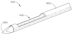
도 7은 도 1a의 삽입기 캐뉼라에 대한 대표적인 대안의 원위 단부 형상을 도시한 투시도이며;
도 8a는 도 7의 삽입기 캐뉼라를 도시한 부분적인 측면 횡단면도이고;
도 8b는 도 7의 삽입기 캐뉼라 내에 삽입된 도 6의 바늘을 도시한 부분적인 측면 횡단면도이며;
도 9는 도 4a의 마커 어플라이어에 대한 대표적인 대안의 원위 단부 형상을 도시한 투시도이고;
도 10은 도 9의 마커 어플라이어를 도시한 부분적인 측면 횡단면도이며;
도 11은 도 7의 삽입기 캐뉼라 내에 삽입된 도 9의 마커 어플라이어를 도시한 부분적인 측면 횡단면도이고;
도 12는 도 1a의 생검 장치의 바늘에 대한 또 다른 대표적인 대안의 원위 단부 형상을 도시한 투시도이며;
도 13a는 도 1a의 삽입기 캐뉼라에 대한 또 다른 대표적인 대안의 원위 단부 형상을 도시한 부분적인 측면 횡단면도이고;
도 13b는 도 13a의 삽입기 캐뉼라 내에 삽입된 도 12의 바늘을 도시한 부분적인 측면 횡단면도이며;
도 14는 도 4a의 마커 어플라이어에 대한 또 다른 대표적인 대안의 원위 단부 형상을 도시한 투시도이고;
도 15는 도 13a의 삽입기 캐뉼라 내에 삽입된 도 14의 마커 어플라이어를 도시한 부분적인 측면 횡단면도이며;
도 16은 또 다른 대표적인 바늘 내에서 커터 내에 배열된 또 다른 대표적인 마커 어플라이어를 도시한 부분적인 측면 횡단면도이고;
도 17은 도 16의 라인 17-17을 따라 절단한 도 16의 바늘과 커터 및 마커 어플라이어를 도시한 횡단면도이며;
도 18은 도 16의 마커 어플라이어, 커터, 및 바늘을 도시한 부분적인 측면 횡단면도로서, 마커 어플라이어의 원위 단부는 커터의 원위 단부에 대해 원위 위치에 위치되고;
도 19는 라인 19-19를 따라 절단한 도 16의 마커 어플라이어, 커터, 및 바늘을 도시한 횡단면도이며;
도 20은 삽입기에 대한 대표적인 대안의 래칭 특징부를 도시한 투시도이고;
도 21은 도 20의 래칭 특징부를 도시한 측면 횡단면도이다.
도면들은 어떤 형식으로든 제한하기 위한 것이 아니라, 본 발명의 다양한 실시예들이 그 외의 다른 여러 방법들, 가령, 도면에는 반드시 도시되지 않은 방법들로 수행될 수 있다고 고려된다. 본 명세서의 일부를 이루고 본 명세서에 통합된 첨부 도면들은 본 발명의 몇몇 형태들을 예시하며 본 발명의 상세한 설명과 함께 본 발명의 원리를 설명하기 위해 이용되지만, 본 발명이 도면에 도시된 특정 장치에만 제한되는 것이 아니라는 사실을 이해해야 한다. While the specification concludes with claims particularly pointing out and distinctly claiming the invention, it is believed that the invention will be better understood from the following description, which describes specific examples in which like reference numerals refer to like elements throughout. In the drawings, some elements or portions of elements are shown in phantom as indicated by dotted lines.
1A is a perspective view of an exemplary inserter cannula and a representative biopsy device, wherein the inserter cannula is separate from the biopsy device;
1B is a perspective view of the biopsy device and the insertion cannula of FIG. 1A with the needles of the biopsy device inserted into the insertion cannula;
Figure 2a is a partial side cross-sectional view of the inserter cannula of Figure la;
Figure 2b is a partial side cross-sectional view showing the needle of the biopsy device and the inserter cannula of Figure 1a with the needle of the biopsy device inserted into the insertion cannula;
Figure 3a is a partial top cross-sectional view of the latching feature of the biopsy device of the inserter cannula of Figure 1a, wherein the latching features are disengaged from each other;
Figure 3b is a partial top cross-sectional view of the latching feature of Figure 3a with the latching features coupled to each other;
4A is a perspective view of a representative biopsy site marker applicator, wherein the plunger of the marker applicator is in a proximal position;
Figure 4b is a perspective view of the marker applicator of Figure 4a in which the plunger of the marker applicator is in a distal position to deploy the marker;
Figure 5 is a perspective view of the marker applicator of Figure 4a inserted in the inserter cannula of Figure 1a wherein the plunger of the marker applicator is in a distal position to deploy the marker;
Figure 6 is a perspective view showing an alternative alternative distal end shape for the needle of the biopsy device of Figure la;
Figure 7 is a perspective view showing an alternative alternative distal end shape for the inserter cannula of Figure la;
Figure 8a is a partial side cross-sectional view of the inserter cannula of Figure 7;
Figure 8b is a partial side cross-sectional view of the needle of Figure 6 inserted into the insertion cannula of Figure 7;
Figure 9 is a perspective view of an alternative alternative distal end shape for the marker applicator of Figure 4a;
Figure 10 is a partial side cross-sectional view of the marker applicator of Figure 9;
Figure 11 is a partial side cross-sectional view of the marker applicator of Figure 9 inserted into the insertion cannula of Figure 7;
12 is a perspective view showing another exemplary alternative distal end shape of the needle of the biopsy device of FIG. 1A;
Figure 13a is a partial side cross-sectional view illustrating another exemplary alternative distal end shape for the insertion cannula of Figure la;
Figure 13b is a partial side cross-sectional view of the needle of Figure 12 inserted into the insertion cannula of Figure 13a;
Figure 14 is a perspective view showing another representative alternative distal end shape for the marker applicator of Figure 4a;
Figure 15 is a partial side cross-sectional view of the marker applicator of Figure 14 inserted in the inserter cannula of Figure 13a;
Figure 16 is a partial side cross-sectional view illustrating another exemplary marker applicator arranged in a cutter within yet another exemplary needle;
17 is a cross-sectional view of the needle and cutter and marker applicator of Fig. 16 cut along line 17-17 of Fig. 16;
Figure 18 is a partial side elevational cross-sectional view of the marker applicator, cutter, and needle of Figure 16 with the distal end of the marker applicator positioned in a distal position with respect to the distal end of the cutter;
Figure 19 is a cross-sectional view of the marker applicator, cutter, and needle of Figure 16 cut along lines 19-19;
20 is a perspective view illustrating an exemplary alternative latching feature for an inserter;
Figure 21 is a side cross-sectional view illustrating the latching feature of Figure 20;
It is contemplated that the drawings are not intended to be limiting in any way, but that the various embodiments of the invention may be practiced in other ways, for example, in ways not necessarily shown in the figures. BRIEF DESCRIPTION OF THE DRAWINGS The accompanying drawings, which are incorporated in and constitute a part of this specification, illustrate some aspects of the invention and together with the description serve to explain the principles of the invention, It should be understood that this is not a limitation.
본 발명의 특정 예들을 기술한 하기 설명은 본 발명의 범위를 제한하도록 사용되어서는 안 된다. 당업자에게는 본 발명의 그 외의 다른 예, 특징, 형태, 실시예들 및 이점들이 본 발명을 실시하기 위해 고려되는 최적의 형태들 중 하나인 예시로서 기술된 하기 설명으로부터 명확해질 것이다. 이해되는 것과 같이, 본 발명은 본 발명의 범위를 벗어나지 않는 그 외의 다른 상이하고 자명한 형태들을 실시할 수 있다. 이에 따라, 도면들과 설명은 본질적으로 제한하려는 목적이 아니라 예시적인 것으로 간주되어야 한다. The following description of specific examples of the present invention should not be used to limit the scope of the invention. Other examples, features, forms, embodiments and advantages of the present invention will become apparent to those skilled in the art from the following description, which is set forth by way of example only, as one of the best modes contemplated for carrying out the invention. As will be realized, the invention may be embodied in other, different and obvious forms without departing from the scope of the invention. Accordingly, the drawings and description are to be regarded as illustrative in nature and not for the purpose of limitation.
I. 대표적인 생검 장치의 개요I. Outline of typical biopsy device
도 1a-2b는 대표적인 생검 장치(10)를 도시한다. 상기 예의 생검 장치(10)는 프로브(30)와 홀스터(20)를 포함한다. 바늘(50)이 프로브(30)로부터 원위 방향으로 연장되며 환자의 조직 내에 삽입되어 조직 샘플을 얻는데, 이것은 밑에서 상세하게 기술될 것이다. 이러한 조직 샘플들은 프로브(30)의 근위 단부에서 조직 샘플 홀더(40) 내에 위치되며, 이것도 밑에서 상세하게 기술될 것이다. 이 예에서 프로브(30)는 홀스터(20)와 탈착가능한 방식으로 결합된다. 본 명세서에서 용어 "홀스터(holster)"를 사용하는 것은 프로브(30)의 임의의 부분이 반드시 홀스터(20)의 임의의 부분 내에 삽입되어야 할 필요가 있다는 것으로 이해되어서는 안 된다. 홀스터(20)와 프로브(30)를 탈착가능한 방식으로 결합시키기 위해 다양한 타입의 구성, 구성요소, 특징부 등(예를 들어, 베이오닛 마운트, 래치, 클램프, 클립, 스냅 피팅 등)이 사용될 수도 있다. 게다가, 몇몇 생검 장치(10)에서, 프로브(30) 및 홀스터(20)는 상기 두 구성요소들이 분리될 수 없도록 일체형 또는 통합형 구성을 가질 수도 있다. 단지 예로서, 프로브(30)와 홀스터(20)가 개별 구성요소들로서 제공되는 경우에, 프로브(30)는 일회용 구성요소로서 제공될 수 있는 반면 홀스터(20)는 재활용 구성요소로서 제공될 수 있다. 본 명세서의 원리에서 볼 때 홀스터(20)와 프로브(30) 사이의 그 외의 다른 적절한 구성 및 기능적 관계는 당업자에게 자명할 것이다. Figures 1A-2B illustrate a representative biopsy device (10). The
이 예에서의 바늘(50)은 캐뉼라(52), 피어싱 팁(54), 상기 팁(54)에 대해 근위 위치에 위치된 가로 구멍(56), 및 허브 부재(80)를 포함한다. 조직 피어싱 팁(54)은 큰 힘을 필요로 하지 않고 팁(54)을 삽입하기 전에 조직 내에 미리 형성되어야 하는 구멍을 필요로 하지도 않고도 조직을 천공하고 관통하도록 구성된다. 대안으로, 팁(54)은 원할 시에는 뭉특할 수 있는데(예를 들어, 둥글거나, 평평하는 등), 가령, 반드시 밑에서 기술되는 대안의 형상들 중 임의의 형상에 제한되지는 않는다. 또한, 팁(54)은 바늘(50)의 그 외의 다른 부분들보다 더 많은 에코발생도(echogenicity)를 제공하여 초음파 영상 하에서 더 향상된 팁(54)의 영상을 제공하도록 구성될 수도 있다. 단지 예로서, 팁(54)은 2010년 9월 3일에 출원된 발명의 명칭이 "Echogenic Needle for Biopsy Device"인 미국 정규특허출원번호 12/875,200호의 원리에 따라 구성될 수 있는데, 상기 미국특허출원은 본 명세서에서 참조문헌으로서 인용된다. 팁(54)을 위해 사용될 수 있는 그 외의 다른 적절한 형상은 본 명세서의 원리에 따라 당업자에게 자명할 것이다. The
가로 구멍(56)은 본 장치(10)의 작동 동안 탈출된 조직(prolapsed tissue)을 수용하도록 크기가 정해진다. 날카로운 원위 에지(도시되지 않음)를 가진 중공의 관형 커터(70)가 바늘(50)의 제 1 루멘(60) 내에 위치된다. 커터(70)는 가로 구멍(56)을 통해 돌출하는 조직으로부터 조직 샘플을 절단하기 위해 가로 구멍(56)을 지나 바늘(50)에 대해 회전되고 병진운동하도록 작동될 수 있다. 예를 들어, 커터(70)는 연장된 위치(도 1)로부터 철회된 위치(도 2b)로 이동될 수 있으며, 가로 구멍(56)을 열면 조직이 상기 구멍을 통해 돌출되고, 그 뒤, 상기 철회된 위치로부터 연장된 위치로 이동하여 돌출 조직이 절단된다. 프로브(30)와 홀스터(20) 내에 있는 기계식 구성요소들은 협력할 수 있어서, 본 명세서에 인용되는 임의의 참조문헌에 기술되거나 그 외의 다른 경우에 기술된 것과 같이, 커터(70)가 상기와 같은 방식으로 작동될 수 있다. 단지 예시적인 또 다른 예로서, 커터(70)는 기계식 구성요소들에 의해 작동되는 대신 또는 그 외에도 공압 방식으로 작동될 수도 있다. 커터를 작동시키는 그 외의 다른 적절한 대안의 방식, 특징, 구성요소, 형상 및 기능들은 본 명세서의 원리에서 볼 때 당업자에게 자명할 것이다. The
가로 구멍(56)이 도 1에서 상부를 향하는 위치에 배열된 것으로 도시되었지만, 바늘(50)은 바늘(50)의 세로축 주위로 임의의 원하는 각위치(angular position)에 가로 구멍(56)을 배열시키도록 수동으로 회전될 수도 있다는 것을 이해해야 한다. 상기 예에서, 바늘(50)의 회전은 허브 부재(80)에 의해 용이하게 수행된다. 허브 부재(80)는 미국 정규특허출원번호 12/953,715호의 원리에 따라 구성되고 작동될 수 있거나 및/또는 그 외의 다른 적절한 임의의 방식으로 구성되고 작동될 수 있다. 바늘(50)의 수동 회전이 제공될 수 있는 그 외의 다른 임의의 적절한 방법들도 본 명세서의 원리에서 볼 때 당업자에게 자명할 것이다. 또한, 바늘(50)의 회전이 다양한 방식으로 자동화될 수도 있는데, 가령, 반드시 본 명세서에 인용되는 다양한 참조문헌에 기술된 다양한 형태의 자동 또는 기계식 바늘 회전을 포함하지만 이들에만 제한되지는 않는다. 1, the
도 2b에 가장 잘 도시된 것과 같이, 바늘(50)은 팁(54)의 근위 부분으로부터 근위 방향으로 연장되는 세로벽(64)을 포함한다. 상기 예에서 벽(64)이 바늘(50)의 전체 길이를 따라 연장되지는 않지만, 상기 벽(64)은 원할 시에는 바늘(50)의 전체 길이를 따라 연장될 수도 있다는 것을 이해해야 한다. 벽(64)은 커터(70)에 대해 평행하고 상기 커터에 대해 가로 방향인 제 2 루멘(62)을 형성한다. 벽(64)은 제 2 루멘(62)과 제 1 루멘(60) 사이에 유체 소통(fluid communication)을 제공하고 커터(70)의 루멘(도시되지 않음)과 제 2 루멘(62) 사이에 유체 소통을 제공하는 복수의 개구(66)를 포함한다. 예를 들어, 제 2 루멘(62)은 생검 장치(10)의 작동 동안 커터(70)의 루멘을 환기시키기 위해 대기를 선택적으로 제공할 수 있다. 개구(66)들은 하나 이상의 개구(68)가 가로 구멍(56)의 원위 에지에 대해 원위 위치에 배열된 세로 위치에 위치되도록 배열된다. 따라서, 제 2 루멘(62)과 커터(70)의 루멘은 심지어 커터(70)의 원위 커팅 에지가 가로 구멍(56)의 원위 에지의 세로 위치에 대해 원위 위치에 배열된 세로 위치에 위치된 위치로 커터(70)가 전진될 때에도 유체 소통하는 상태로 유지될 수 있다. 물론, 본 명세서에 기술된 그 외의 다른 임의의 구성요소와 같이, 그 외의 다른 임의의 적절한 형상들도 사용될 수 있다. As best shown in FIG. 2B, the
프로브(30)는 바늘(50)의 적어도 일부분과 유체 소통하여 커터(70)의 세로 위치와 같이 임의의 적절한 상태에 따라 바늘(50)의 적어도 일부분의 공압 상태가 선택적으로 변경되는 밸브 조립체를 포함할 수 있다. 예를 들어, 이러한 밸브 조립체는 제 2 루멘(62)의 공압 상태를 선택적으로 변경시킬 수 있다. 이러한 밸브 조립체는 미국 공개공보번호 2010/0317997호의 원리, 미국 정규특허출원번호 12/953,715호의 원리 및/또는 그 외의 원리에 따라 구성될 수 있다. 그 외에도 또는 대안으로, 가령, 미국 공개공보번호 2008/0214955호에 기술된 것과 같은 진공원 및/또는 진공 캐니스터에 의해 밸브장치들이 제공될 수 있다. 그 외의 다른 적절한 대안의 바늘(50)의 형태, 특징, 구성요소, 형상 및 기능은 본 명세서에서 볼 때 당업자에게 자명할 것이다. The
이 예에서 조직 샘플 홀더(40)는 커터(70)의 중공 내부를 통해 근위 방향으로 소통되고 커터(70)에 의해 절단된 조직 샘플들을 수용하도록 구성된다. 조직 샘플 홀더(40)는 조직 샘플 홀더(40)를 프로브(30)로부터 제거할 필요 없이 사용자가 상기 절단된 조직 샘플들을 조직 샘플 홀더(40)로부터 제거할 수 있게 하는 하나 또는 그 이상의 탈착형 트레이(도시되지 않음)를 포함할 수 있다. 몇몇 이러한 형태에서, 조직 샘플 홀더(40)는 2010년 9월 10일에 출원된 발명의 명칭이 "Biopsy Device Tissue Sample Holder with Removable Basket"인 미국 가특허출원번호 61/381,466호의 원리에 따라 구성될 수 있는데, 상기 미국특허출원은 본 명세서에서 참조문헌으로서 인용된다. 그 외에도 또는 대안으로, 조직 샘플 홀더(130)는 커터(70)와 진공원과 유체 소통하고 개별 조직 수용 챔버를 커터(70)에 성공적으로 인덱싱하도록 회전될 수 있는 회전형 매니폴드(도시되지 않음)를 포함할 수 있다. 단지 예로서, 조직 샘플 홀더(40)는 미국 공개공보번호 2008/0214955호의 원리에 따라 작동될 수 있고 구성될 수 있는데, 이 미국 공개공보는 본 명세서에서 참조문헌으로 인용된다. 또 다른 단지 예시적인 예로서, 조직 샘플 홀더(40)는 2010년 6월 24일에 공개된 발명의 명칭이 "Biopsy Device with Discrete Tissue Chambers"인 미국 공개공보번호 2010/0160824호의 원리에 따라 작동될 수 있고 구성될 수 있는데, 상기 미국 공개공보는 본 명세서에서 참조문헌으로서 인용된다. 본 명세서의 원리에서 볼 때 조직 샘플 홀더(40)가 구성되고 작동될 수 있는 그 외의 다른 적절한 방법들도 당업자에게는 자명할 것이다. In this example,
생검 장치(10)는 진공원(도시되지 않음), 가령, 진공 펌프를 포함할 수 있다. 단지 예로서, 진공원이 프로브(30) 내에 일체형으로 구성될 수 있고, 홀스터(20) 내에 일체형으로 구성될 수 있거나 및/또는 모두 개별적인 구성요소일 수도 있다. 진공원이 프로브(30)와 홀스터(20)로부터 개별적인 구성요소인 경우, 진공원은 하나 또는 그 이상의 도관, 가령, 가요성 튜브를 통해 프로브(30) 및/또는 홀스터(20)와 결합될 수도 있다. 진공원이 바늘(50)과 조직 샘플 홀더(40)와 유체 소통되는 상태에 있을 수 있다는 것을 이해해야 한다. 따라서, 진공원은 조직을 바늘(50)의 가로 구멍(56) 내로 끌어당기도록 작동될 수 있다. 상기 예에서 조직 샘플 홀더(40)도 커터(70)와 유체 소통상태에 있다. 따라서, 진공원이 절단된 조직 샘플들을 커터(70)의 중공 내부를 통해 조직 샘플 홀더(40) 내로 끌어당기도록 작동될 수도 있다. 몇몇 경우에서, 진공원이 미국 공개공보번호 2008/0214955호의 원리에 따라 제공된다. 그 외에도 또는 대안으로, 진공원은 미국 정규특허출원번호 12/953,715호의 원리에 따라 제공될 수도 있다. 또 다른 단지 예시적인 예로서, 진공원이 2010년 2월 22일에 출원된 발명의 명칭이 "Biopsy Device with Auxiliary Vacuum Source"인 미국 정규특허출원번호 12/709,695호의 원리에 따라 제공될 수도 있는데, 상기 미국 특허출원은 본 명세서에서 참조문헌으로서 인용된다. 진공원이 제공될 수 있는 그 외의 다른 적절한 방법들은 본 명세서의 원리에서 볼 때 당업자에게 자명할 것이다. 또한, 원할 시에, 진공원이 제거될 수도 있다는 것을 이해해야 한다. The
상기 예에서의 생검 장치(10)는 상기 생검 장치(10)가 사용자의 한 손으로 작동될 수 있도록 구성되고 크기가 정해진다. 특히, 사용자는 생검 장치(10)를 쥐고, 바늘(50)을 환자의 가슴 내에 삽입하여, 환자의 가슴 내에서부터 하나 또는 복수의 조직 샘플들을 채취할 수 있는데, 이 모든 과정은 단지 한 손을 사용하여 수행할 수 있다. 대안으로, 사용자는 두 손을 사용하거나 및/또는 임의의 원하는 보조장치를 사용하여 생검 장치(10)를 쥘 수도 있다. 생검 장치(10)는 테이블 또는 고정기기에 장착하도록 구성될 수 있으며 주촉성 유도(stereotactic guidance) 하에서 사용될 수 있다는 것을 이해해야 한다. 물론, 대신에, 생검 장치(10)는 초음파 유도, MRI 유도, PEM 유도, BSGI 유도 하에서 또는 그 외의 다른 경우에서도 사용될 수 있다. 몇몇 형태에서, 사용자는 바늘(50)을 환자의 가슴 내에 단지 한번 삽입하여 복수의 조직 샘플들을 채취할 수 있다. 이러한 조직 샘플들은 조직 샘플 홀더(40) 내에 공압 방식으로 배열될 수 있으며 분석을 위해 추후에 조직 샘플 홀더(40)로부터 빼낼 수도 있다. 본 명세서에 기술된 예들이 종종 환자의 가슴으로부터 생검 샘플들을 채취하는 것을 지칭하지만, 생검 장치(10)가 그 외의 다른 여러 목적을 위한 그 밖의 수술에서도 사용될 수 있으며 환자의 해부학적 구조의 다양한 그 외의 다른 부분(가령, 예컨대, 전립선, 갑상선 등)들에서도 사용될 수 있다는 것을 이해해야 한다. 생검 장치(10)에 대한 그 외의 다른 적절한 구성요소, 특징, 형상 및 기능들은 본 명세서에서 볼 때 당업자에게 자명할 것이다. The
II. 개방된 원위 단부를 가진 대표적인 삽입기 캐뉼라II. An exemplary insert cannula with an open distal end
몇몇 형태에서, 바늘(50)이 환자의 조직 내에 직접 삽입되어 캐뉼라(52)의 삽입된 전체 길이의 외측 표면이 환자의 조직과 직접 접촉된다. 그 외의 다른 몇몇 형태에서는 삽입기 캐뉼라가 사용된다. 단지 예로서, 개방된 원위 팁을 가진 삽입기 캐뉼라가 우선 환자의 조직 내에 삽입될 수 있다. 몇몇 경우에서는, 2개가 환자의 조직 내에 삽입될 때 날카로운 원위 팁(삽입기 캐뉼라의 개방된 원위 단부로부터 돌출된)을 가진 폐색구가 삽입기 캐뉼라 내에 배열될 수 있다. 환자의 조직 내에 삽입되는 동안 폐색구가 사용되면, 삽입기 캐뉼라가 조직 내에 원하는 깊이에 도달한 후에 폐색구가 제거될 수도 있다. 그 뒤, 바늘(50) 및/또는 그 외의 다른 기기들은 캐뉼라의 원위 단부에서 조직에 도달하기 위해 삽입기 캐뉼라 내에 삽입될 수도 있다. In some forms, the
몇몇 형태에서, 가령, 생검 장치의 바늘이 날카로운 팁을 가진 형태에서는, 2개가 함께 환자의 조직 내에 삽입되기 전에 삽입기가 바늘과 결합될 수도 있다. 이에 대한 단지 예시적인 예가 도 1a-2b에 도시된다. 특히, 도 1a는 생검 장치(10)의 바늘(50)이 삽입기(100) 내에 삽입되기 전의 대표적인 삽입기(100)와 생검 장치(10)를 도시한다. 도 1b는 삽입기(100) 내에 삽입된 바늘(50)을 도시한다. 도 1a-1b에 도시된 것과 같이, 상기 예의 삽입기(100)는 캐뉼라(102), 개방된 원위 단부(106)에서의 한 쌍의 원위 리브(104), 및 래칭 특징부(180)를 포함한다. 래칭 특징부(180)는 삽입기(100)를 생검 장치(10)에 선택적으로 고정시키도록 작동될 수 있는데, 이는 밑에서 더욱 상세하게 기술될 것이다. 도 2a에 도시된 것과 같이, 캐뉼라(102)는 개방된 원위 단부(106)와 유체 소통하는 내부 루멘(112)을 형성한다. 도 2a에 도시된 것과 같이, 리브(104)는 내부 방향으로 약간 굽어지도록 탄성적으로 편향되며, 틈(110)이 리브(104)들 사이에 형성되어 리브(104)가 서로를 향해 또는 서로로부터 멀어지도록 용이하게 독립적으로 운동한다. In some forms, for example, in the form in which the needle of the biopsy device has a sharp tip, the inserter may be combined with the needle before the two are inserted together into the patient's tissue. Only exemplary examples of this are shown in Figs. 1A-2B. 1A shows an
도 1b 및 2b에 가장 잘 도시된 것과 같이, 바늘(50)의 캐뉼라(52)가 캐뉼라(102)의 루멘(112) 내에 완전히 삽입될 때, 바늘(50)의 원위 부분이 캐뉼라(102)로부터 원위 방향으로 돌출된다. 특히, 가로 루멘(56)이 완전히 노출되는데, 상기 루멘은 리브(104)의 원위 에지(108)들에 대해 원위 방향으로 위치된다. 도 2a(릴렉싱된 리브(104))와 도 2b(수축된 리브(104))를 비교함으로써 볼 수 있는 것과 같이, 캐뉼라(52)의 외측 직경은 릴렉싱된 리브(104)들 사이에 형성된 내측 직경보다 더 커서, 캐뉼라(52)가 캐뉼라(102) 내에 삽입될 때 캐뉼라(52)는 리브(104)를 외부 방향으로 편향시킨다. 특히, 리브(104)는 상기 리브들이 캐뉼라(102)의 측벽의 근위 부분들과 실질적으로 나란하게 정렬되도록 편향된다. 따라서, 리브(104)는 바늘(50)의 캐뉼라(52)에 대해 탄성적으로 지탱된다(resiliently bear). 몇몇 형태에서, 리브(104)의 원위 에지(108)들이 챔퍼링되어(chamfered) 캐뉼라(52)의 외측 직경으로부터 캐뉼라(102)의 외측 직경으로 실질적으로 부드럽게 전이된다. 1B and 2B, when the
대표적인 사용 방법에서, 삽입기(100)는 도 1b 및 2b에 도시된 것과 같이 바늘(50)과 결합된다. 원위 위치에서 커터(70)가 가로 구멍(56)을 효과적으로 폐쇄하면, 삽입기(100)와 바늘(50)은 함께 환자의 조직 내에 삽입된다. 상기와 같이 삽입되는 동안 팁(54)은 환자의 조직을 천공하고 관통한다. 그 뒤, 커터(70)는 (예를 들어, 진공 보조장치 등을 사용하여) 조직 샘플 홀더(40) 내에 배치되는 하나 또는 그 이상의 조직 샘플들을 채취하도록 왕복운동한다(reciprocated). 원하는 개수의 조직 샘플들이 채취되고 나면, 바늘(50)은 삽입기(100)로부터 결합해제되고(decoupled), 캐뉼라(52)는 캐뉼라(102)로부터 철회되어, 캐뉼라(102)가 환자의 조직 내에 위치된 상태로 유지된다. 그 뒤, 마커 어플라이어가 캐뉼라(102)의 루멘(112) 내에 삽입되어 하나 또는 그 이상의 마커를 생검 부위에 배치시킬 수 있다(deposit). 그 외에도 또는 대안으로, 하나 또는 그 이상의 약제(medicament), 방사선요법 펠릿(brachytherapy pellet), 및/또는 그 외의 다른 물질이 캐뉼라(102)의 루멘(112)을 통해 생검 부위에 제공될 수 있다. 그 외에도 또는 대안으로, 그 외의 다른 여러 종류의 기기들이 캐뉼라(102)의 루멘(112)을 통해 삽입되어 생검 부위에 도달할 수 있다. 그 뒤, 삽입기(100)는 환자의 조직으로부터 빼내질 수 있다. 삽입기(100)가 사용될 수 있는 그 외의 다른 적절한 방법들은 본 명세서의 원리에서 볼 때 당업자에게 자명할 것이다. In an exemplary method of use, the
상기 예의 삽입기(100)는 래칭 특징부(180)를 통해 생검 장치(10)와 선택적으로 결합되도록 작동될 수 있다. 도 3a-3b에 가장 잘 도시된 것과 같이, 상기 예의 래칭 특징부(180)는 한 쌍의 래치(182)와 버튼(184)을 포함한다. 래치(182)는 허브 부재(80)의 상호보완적인 슬롯(82) 내에 수용된다. 래치(182)는 허브 부재(80) 내에 래치(182)를 보유하는 외부를 향하는 돌출부(186)를 포함한다. 래치(182)와 버튼(184)은 탄성 암(188) 위에 위치되는데, 상기 탄성 암은 래치(182)를 도 3a-3b에 도시된 위치들로 탄성적으로 편향시켜 래치(182)들이 내부 방향으로 굽어질 수 있게 하여 허브 부재(80)의 슬롯(82) 내에 수용되게 한다. 암(188)들은 버튼(184)이 서로를 향해 내부 방향으로 눌러질 수 있게 하여 래치(182)가 슬롯(82)으로부터 결합해제된다. 도 3a-3b에서 볼 수 있는 것과 같이, 래칭 특징부(180)의 내부는 캐뉼라(52)의 원위 단부가 삽입기(100)의 루멘(112) 내에 안내되도록 도움을 주는 램프(190)를 포함한다. 도시되지는 않았지만, 삽입기는, 가령, 삽입기(100)로부터 체액이 유출되는 것을 줄이거나 방지하기 위해 하나 또는 그 이상의 내부 밸브 또는 밀봉부(seal)를 포함할 수도 있다는 것을 이해해야 한다. 또한, 삽입기(100)가 그 외의 다른 다양한 방법으로 생검 장치(10)와 선택적으로 결합될 수 있다는 것을 이해해야 한다. 래칭 특징부(180)를 위한 그 외의 다른 적절한 변형예는 본 명세서에서 볼 때 당업자에게 자명할 것이다. 게다가, 삽입기(100)는 반드시 생검 장치(10)에 고정될 필요는 없으며, 이에 따라 래칭 특징부(180)와 상기 래칭 특징부의 변형예들은 원할 시에는 간단하게 제거될 수도 있다. The
위에서 언급한 것과 같이, 바늘(50)이 삽입기(100)로부터 철회되고 삽입기(100)는 환자의 조직 내에 유지되는 경우, 삽입기(100)는 하나 또는 그 이상의 생검 부위 마커를 전개시키기 위해 생검 부위 마커 어플라이어 기기를 생검 부위로 안내하도록 사용될 수도 있다. 예를 들어, 도 4a-4b는 삽입기(100)와 사용될 수 있는 대표적인 마커 어플라이어(200)를 도시한다. 이 예에서의 마커 어플라이어(200)는 날카로운 팁(206)이 있는 개방된 원위 단부(204)를 가진 캐뉼라(202)를 포함한다. 생검 부위 마커(210)가 캐뉼라(202) 내에서 슬라이딩 이동가능하게 배열된다. 푸시 로드(220)도 캐뉼라(202) 내에서 슬라이딩 이동가능하게 배열되며 도 4b에 도시된 것과 같이, 개방된 원위 단부(204)를 통해 마커(210)를 외부 방향으로 밀도록 작동될 수 있다. 마커(210)를 전개시키기 위해 푸시 로드(220)를 원위 방향으로 전진시키고 마커 어플라이어(200)를 고정하기 위해 사용자의 한 손으로 핑거 그립(222)과 플런저(224)가 조작될 수 있다. 단지 예로서, 마커 어플라이어(200)는 몇몇 형태에서 미국 오하이오주 신시내티에 위치된 Devicor Medical Products, Inc.사의 CORMARK™ 장치를 포함한다. As mentioned above, when the
도 5에 도시된 것과 같이, 마커 어플라이어(200)의 캐뉼라(202)는 생검 장치(10)의 바늘(50)이 삽입기(100)의 캐뉼라(102)로부터 철회되고 난 뒤 생검 부위에서 마커(210)를 전개시키기 위해 삽입기(100)의 캐뉼라(102)를 통해 삽입될 수 있다. 도시된 것과 같이, 캐뉼라(102, 202)의 길이는 마커 어플라이어(200)의 원위 단부(204)가 삽입기(100)의 원위 단부(106)로부터 원위 방향으로 돌출하도록 형성된다. 마커 어플라이어(200)의 원위 단부(204)는 삽입기(100)의 원위 단부(106)로부터 임의의 적절한 정도로 원위 방향으로 돌출될 수 있다는 것을 이해해야 한다. 상기 예에서, 래칭 특징부(180)는 마커 어플라이어(200)의 임의의 구성요소와 결합되지 않지만, 그 외의 다른 몇몇 형태에서는 래칭 특징부(180)가 마커 어플라이어(200)의 한 구성요소와 결합될 수도 있다. 마커 어플라이어(200)와 삽입기(100)에 대한 그 외의 다른 적절한 구성요소, 특징, 형상 및 관계는 본 명세서의 원리에서 볼 때 당업자에게 자명할 것이다. 5, the
III. 폐쇄된 원위 단부와 램프된 근위 내측면을 가진 대표적인 삽입기 캐뉼라III. An exemplary insert cannula with a closed distal end and a ramped proximal inner surface
도 7-8b는 대표적인 대안의 삽입기(400)와 바늘(300)을 도시한다. 바늘(300)이 생검 장치(10)용 바늘(50) 대신에 사용될 수 있다는 것을 이해해야 한다. 이와 비슷하게, 삽입기(400)가 삽입기(100) 대신에 사용될 수 있다는 것을 이해해야 한다. 따라서, 삽입기(400)와 바늘(300)의 근위 부분은 위에서 기술한 것과 같이 삽입기(100)와 바늘(50)의 근위 부분과 같이 형성될 수 있다. 게다가, 바늘(300)과 삽입기(400)는 위에서 기술한 것과 같이 바늘(50)과 삽입기(100)의 사용 방법과 같이 사용될 수 있다. 물론, 바늘(300) 및/또는 삽입기(400)는 그 외의 다른 임의의 적절한 대안의 형상을 가질 수 있으며, 바늘(300) 및/또는 삽입기(400)는 그 외의 다른 여러 적절한 방법들로도 사용될 수 있다. 7-8B illustrate an alternative
도 6에 도시된 것과 같이, 상기 예에서의 바늘(300)은 폐쇄된 원위 단부(304)에 대해 근위 위치에 위치된 가로 구멍(306)과 뭉특한 폐쇄된 원위 단부(304)를 가진 캐뉼라(302)를 포함한다. 하부 채널 영역(310)이 개방된 원위 단부(314)를 포함한다. 개방된 원위 단부(314)는 폐쇄된 원위 단부(304)의 세로 위치에 대해 근위 위치에 있는 세로 위치에 위치된다. 도 8b에 가장 잘 도시된 것과 같이, 캐뉼라(302)는 커터(70)를 수용하도록 구성된 제 1 루멘(308)을 형성한다. 도 8b에서 볼 수 있는 것과 같이, 하부 채널 영역(310)의 원위 부분과 세로벽(320)은 제 1 루멘(308)에 대해 평행하고 상기 제 1 루멘에 대해 가로 방향으로 배열된 제 2 루멘(322)을 형성한다. 도시되지는 않았지만, 제 1 루멘(308)과 제 2 루멘(322) 사이에 유체 소통을 제공하기 위해 하나 또는 그 이상의 개구가 벽(320) 내에 형성될 수 있다는 것을 이해해야 한다. 6, the
도 7과 8a에 도시된 것과 같이, 상기 예의 삽입기(400)는 캐뉼라(402), 피어싱 팁(404), 및 상기 팁(404)에 대해 근위 위치에 위치된 가로 구멍(406)을 포함한다. 상기 예의 조직 피어싱 팁(404)은 폐쇄되고 큰 힘이 필요 없이 또한 팁(404)이 삽입되기 전에 조직 내에 미리 형성되어야 하는 구멍을 필요로 하지도 않고도 조직을 천공하고 관통하도록 구성된다. 또한, 팁(404)은 삽입기(400)의 그 외의 다른 부분들보다 더 많은 에코발생도(echogenicity)를 제공하여 초음파 영상 하에서 더 향상된 팁(404)의 영상을 제공하도록 구성될 수도 있다. 단지 예로서, 팁(404)은 미국 정규특허출원번호 12/875,200호의 원리 중 임의의 원리에 따라 구성될 수 있다. 팁(404)을 위해 사용될 수 있는 그 외의 다른 적절한 형상은 본 명세서의 원리에 따라 당업자에게 자명할 것이다. 7 and 8A, the
도 8a-8b에 가장 잘 도시된 것과 같이, 삽입기(400)는 근위 방향을 향하는 벽(410), 램프(412), 및 상기 램프(412)로부터 벽(410)으로 세로 방향으로 연장되는 쉘프(414)를 추가로 포함한다. 상기 특징부(410, 412, 414)는 팁(404)에 대해 바로 근위 위치에 배열된다. 도 8b에서 볼 수 있는 것과 같이, 가로 구멍(306, 406)은 바늘(300)의 캐뉼라(302)가 삽입기(400)의 캐뉼라(402) 내에 삽입될 때 실질적으로 나란하게 정렬된다. 게다가, 폐쇄된 원위 단부(304)는 근위 방향을 향하는 벽(410)과 접하며 쉘프(414) 위에 위치된다. 하부 채널 영역(310)의 개방된 원위 단부(314)는 램프(412)에 대해 바로 근위 위치에 위치된다. 달리 말하면, 원위 단부(304)의 세로 위치에 대해 원위 단부(314)의 세로 위치는 도 8b에 도시된 것과 같이 바늘(300)의 캐뉼라(302)가 삽입기(400)의 캐뉼라(402) 내에 삽입될 때 쉘프(414)와 램프(412)를 위한 간격(clearance)을 제공한다. 게다가, 램프(412)의 수직 높이와 원위 단부(304, 314)를 분리하는 수직 높이는 실질적으로 비슷하며, 바늘(300)의 캐뉼라(302)가 삽입기(400)의 캐뉼라(402) 내에 삽입될 때 쉘프(414)와 램프(412)를 위한 추가적인 간격을 제공한다. 8A-8B, the
대표적인 사용 방법에서, 삽입기(400)는 도 8b에 도시된 것과 같이 바늘(300)과 결합된다. 커터(70)가 원위 위치에서 가로 구멍(306, 406)을 효과적으로 폐쇄하면, 삽입기(400)와 바늘(300)은 환자의 조직 내에 함께 삽입된다. 상기와 같이 삽입되는 동안 팁(404)은 환자의 조직을 천공하고 관통한다. 그 뒤, 커터(70)는 (예를 들어, 진공 보조장치 등을 사용하여) 조직 샘플 홀더(40) 내에 배치되는 하나 또는 그 이상의 조직 샘플들을 채취하도록 왕복운동한다. 원하는 개수의 조직 샘플들이 채취되고 나면, 바늘(300)은 삽입기(400)로부터 결합해제되고, 캐뉼라(302)는 캐뉼라(402)로부터 철회되어, 캐뉼라(402)가 환자의 조직 내에 위치된 상태로 유지된다. 그 뒤, 마커 어플라이어가 캐뉼라(402) 내에 삽입되어 하나 또는 그 이상의 마커를 생검 위치에 배치시킬 수 있다(deposit). 그 외에도 또는 대안으로, 하나 또는 그 이상의 약제, 방사선요법 펠릿(brachytherapy pellet), 및/또는 그 외의 다른 물질이 캐뉼라(402)를 통해 생검 부위에 제공될 수 있다. 그 외에도 또는 대안으로, 그 외의 다른 여러 종류의 기기들이 캐뉼라(402)를 통해 삽입되어 생검 부위에 도달할 수 있다. 그 뒤, 삽입기(400)는 환자의 조직으로부터 빼내질 수 있다. 삽입기(400)가 사용될 수 있는 그 외의 다른 적절한 방법들은 본 명세서의 원리에서 볼 때 당업자에게 자명할 것이다. In an exemplary method of use, the
위에서 기술한 것과 같이, 삽입기(400)가 환자의 조직 내에 유지되면서도 바늘(300)이 삽입기(400)로부터 철회되는 경우 삽입기(400)는 하나 또는 그 이상의 생검 부위 마커를 전개시키기 위해 생검 부위 마커 어플라이어 기기를 생검 부위로 안내하도록 사용될 수 있다. 예를 들어, 도 9-11은 삽입기(400)와 사용될 수 있는 대표적인 마커 어플라이어(500)를 도시한다. 이 예에서의 마커 어플라이어(500)는 둥근 팁(506)과 상기 팁(506)에 대해 근위 위치에 위치된 가로 구멍(508)이 있는 폐쇄된 원위 단부(504)를 가진 캐뉼라(502)를 포함한다. 마커 어플라이어(500)는 제 1 램프(510), 제 2 램프(512), 및 제 1 램프(510)로부터 제 2 램프(512)로 세로 방향으로 연장되는 쉘프(514)를 추가로 포함한다. 램프(510)는 생검 부위 마커(518)가 너무 일찍 가로 구멍(508)을 통해 의도치않게 떨어져 나가는 것을 방지하도록 구성된다. 램프(512)는 가로 구멍(508)의 원위 단부로 이어지고(lead) 가로 구멍(508)을 통해 마커(518)를 외부 방향으로 안내하도록 구성된다. 특히, 푸시 로드(520)가 캐뉼라(502) 내에서 슬라이딩 이동가능하게 배열되며 마커(210)를 램프(510)를 지나 쉘프(514)를 따라 램프(512)까지 밀어서 가로 구멍(508)을 통해 나가도록 작동될 수 있다. 또한, 마커 어플라이어(500)는 마커(518)를 전개시키기 위해 푸시 로드(520)를 원위 방향으로 전진시키고 마커 어플라이어(500)를 고정하기 위해 사용자의 한 손으로 조작될 수 있는 핑거 그립과 플런저(도시되지 않음)를 포함할 수 있다. 단지 예로서, 마커 어플라이어(500)는 몇몇 형태에서 미국 오하이오주 신시내티에 위치된 Devicor Medical Products, Inc.사의 MAMMOMARK™ 장치를 포함한다. As described above, when the
도 11에 도시된 것과 같이, 마커 어플라이어(500)의 캐뉼라(502)는 바늘(300)이 삽입기(400)의 캐뉼라(402)로부터 철회된 후에 생검 부위에서 마커(518)를 전개시키기 위해 삽입기(400)의 캐뉼라(402)를 통해 삽입될 수 있다. 도시된 것과 같이, 캐뉼라(402, 502)의 길이는 마커 어플라이어(500)의 캐뉼라(502)가 삽입기(400)의 캐뉼라(402) 내에 삽입될 때 가로 구멍(406, 508)이 실질적으로 나란하게 정렬되도록 형성된다. 게다가, 둥근 팁(506)은 근위 방향을 향하는 벽(410)과 접하며 쉘프(414) 위에 위치된다. 따라서, 둥근 팁(506)은 가로 구멍(406)에 대해 원위 위치에 있는 캐뉼라(402)의 측벽의 최원위 부분과 쉘(414) 사이에 포획되고(trapped) 이에 따라 둥근 팁(506)은 가로 구멍(406)으로부터 돌출되지 않는다. 도 11에서 볼 수 있는 것과 같이, 캐뉼라(402)의 내측 직경은 캐뉼라(502)의 외측 직경보다 실질적으로 더 크며, 이에 따라 캐뉼라(502)의 외측 직경과 캐뉼라(402)의 내측 직경 사이에 틈(420)이 형성된다. 따라서, 마커 어플라이어(500)의 캐뉼라(502)가 삽입기(400)의 캐뉼라(402) 내에 삽입되는 초기 단계 동안, 캐뉼라(502)는 둥근 팁(506)이 램프(412)에 도달될 때까지 캐뉼라(402)의 하부 영역을 따라 슬라이딩 이동될 수 있다는 것을 이해해야 한다. 램프(412)는 둥근 팁(506)을 쉘프(414)까지 안내하고 그 뒤 벽(410)으로 안내할 수 있으며 따라서 캐뉼라(502)의 원위 단부(504)가 올라가게 한다. 이는 구멍(406, 508)을 적절하게 정렬하는 데 도움을 줄 수 있으며 그렇지 않는 경우 생검 부위에서 가로 구멍(406)을 통해 마커(518)가 적절하게 빠지기 쉽게 할 수 있다. 또한, 하나 또는 그 이상의 스페이서(도시되지 않음)는, 가령, 캐뉼라(502)가 가요성의 재료로 형성되는 몇몇 형태에서와 같이, 캐뉼라(402) 내에서 캐뉼라(502)가 버클링(buckling)되는 것을 실질적으로 방지하기 위해, 캐뉼라(502)의 길이를 따라 위치될 수도 있다는 것을 이해해야 한다. 마커 어플라이어(500)와 삽입기(400)에 대한 그 외의 다른 적절한 구성요소, 특징, 형상, 및 관계는 본 명세서에서 볼 때 당업자에게 자명할 것이다. 또한, 몇몇 형태에서, 캐뉼라(502)는 커터(70)가 근위 위치에 있고 바늘(300)이 여전히 삽입기(400) 내에 삽입된 상태에 있을 때 커터(70)를 통해 삽입될 수 있으며, 이에 따라 마커(518)는 3개의 구멍(306, 406, 508) 모두를 통해 전개될 수도 있다는 것을 이해해야 한다. 11, the
IV. 폐쇄된 원위 단부와 평평한 근위 내측면을 가진 대표적인 삽입기 캐뉼라IV. An exemplary insertion cannula with a closed distal end and a flat proximal inner surface
도 12-13b는 또 다른 대표적인 대안의 삽입기(700)와 바늘(600)을 도시한다. 바늘(600)은 생검 장치(10)용 바늘(50) 대신에 사용될 수 있다는 것을 이해해야 한다. 이와 비슷하게, 삽입기(700)는 삽입기(100) 대신에 사용될 수 있다는 것을 이해해야 한다. 따라서, 삽입기(700)와 바늘(600)의 근위 부분들은 위에서 기술한 것과 같이 삽입기(100)와 바늘(50)의 근위 부분들과 같이 형성될 수 있다. 게다가, 바늘(600)과 삽입기(700)는 위에서 기술한 것과 같이 바늘(50)과 삽입기(100)의 사용 방법과 같이 사용될 수 있다. 물론, 바늘(600) 및/또는 삽입기(700)는 그 외의 다른 임의의 적절한 대안의 형상을 가질 수 있으며, 바늘(600) 및/또는 삽입기(700)는 그 외의 다른 여러 적절한 방법들로도 사용될 수 있다. Figs. 12-13b illustrate another exemplary
도 12에 도시된 것과 같이, 상기 예에서의 바늘(600)은 폐쇄된 원위 단부(604)에 대해 근위 위치에 위치된 가로 구멍(606)과 뭉특한 폐쇄된 원위 단부(604)를 가진 캐뉼라(602)를 포함한다. 도 13b에 가장 잘 도시된 것과 같이, 캐뉼라(602)는 커터(70)를 수용하도록 구성된 제 1 루멘(608)을 형성한다. 도 13b에서 볼 수 있는 것과 같이, 캐뉼라(602)의 하부 영역과 세로벽(620)은 제 1 루멘(608)에 대해 평행하고 상기 제 1 루멘에 대해 가로 방향으로 배열된 제 2 루멘(622)을 형성한다. 벽(620)은 제 2 루멘(622)과 제 1 루멘(608) 사이에 유체 소통을 제공하고 커터(70)의 루멘(도시되지 않음)과 제 2 루멘(622) 사이에 유체 소통을 제공하는 복수의 개구(624)를 포함한다. 개구(624)들은 하나 이상의 개구(626)가 가로 구멍(606)의 원위 에지에 대해 원위 위치에 배열된 세로 위치에 위치되도록 배열된다. 따라서, 제 2 루멘(622)과 커터(70)의 루멘은 심지어 커터(70)의 원위 커팅 에지가 가로 구멍(606)의 원위 에지의 세로 위치에 대해 원위 위치에 배열된 세로 위치에 위치된 위치로 커터(70)가 전진될 때에도 유체 소통하는 상태로 유지될 수 있다. 물론, 본 명세서에 기술된 그 외의 다른 임의의 구성요소와 같이, 그 외의 다른 임의의 적절한 형상들도 사용될 수 있다. 12, the
도 13a-13b에 도시된 것과 같이, 상기 예의 삽입기(700)는 캐뉼라(702), 피어싱 팁(704), 및 상기 팁(704)에 대해 근위 위치에 위치된 가로 구멍(706)을 포함한다. 상기 예의 조직 피어싱 팁(704)은 폐쇄되고 큰 힘이 필요 없이 또한 팁(704)이 삽입되기 전에 조직 내에 미리 형성되어야 하는 구멍을 필요로 하지도 않고도 조직을 천공하고 관통하도록 구성된다. 또한, 팁(704)은 삽입기(700)의 그 외의 다른 부분들보다 더 많은 에코발생도를 제공하여 초음파 영상 하에서 더 향상된 팁(704)의 영상을 제공하도록 구성될 수도 있다. 단지 예로서, 팁(704)은 미국 정규특허출원번호 12/875,200호의 원리 중 임의의 원리에 따라 구성될 수 있다. 팁(704)을 위해 사용될 수 있는 그 외의 다른 적절한 형상은 본 명세서의 원리에 따라 당업자에게 자명할 것이다. 상기 예의 삽입기(700)는 팁(704)에 대해 바로 근위 위치에 있는 근위 방향을 향하는 벽(710)을 추가로 포함한다. 도 8b에서 볼 수 있는 것과 같이, 가로 구멍(606, 706)은 바늘(600)의 캐뉼라(602)가 삽입기(700)의 캐뉼라(702) 내에 삽입될 때 실질적으로 나란하게 정렬된다. 게다가, 폐쇄된 원위 단부(604)는 근위 방향을 향하는 벽(710)과 접한다. 13A-13B, the
대표적인 사용 방법에서, 삽입기(700)는 도 13b에 도시된 것과 같이 바늘(600)과 결합된다. 커터(70)가 원위 위치에서 가로 구멍(606, 706)을 효과적으로 폐쇄하면, 삽입기(700)와 바늘(600)은 환자의 조직 내에 함께 삽입된다. 상기와 같이 삽입되는 동안 팁(704)은 환자의 조직을 천공하고 관통한다. 그 뒤, 커터(70)는 (예를 들어, 진공 보조장치 등을 사용하여) 조직 샘플 홀더(40) 내에 배치되는 하나 또는 그 이상의 조직 샘플들을 채취하도록 왕복운동한다. 원하는 개수의 조직 샘플들이 채취되고 나면, 바늘(600)은 삽입기(700)로부터 결합해제되고, 캐뉼라(602)는 캐뉼라(702)로부터 철회되어, 캐뉼라(702)가 환자의 조직 내에 위치된 상태로 유지된다. 그 뒤, 마커 어플라이어가 캐뉼라(702) 내에 삽입되어 하나 또는 그 이상의 마커를 생검 위치에 배치시킬 수 있다(deposit). 그 외에도 또는 대안으로, 하나 또는 그 이상의 약제, 방사선요법 펠릿, 및/또는 그 외의 다른 물질이 캐뉼라(702)를 통해 생검 부위에 제공될 수 있다. 그 외에도 또는 대안으로, 그 외의 다른 여러 종류의 기기들이 캐뉼라(702)를 통해 삽입되어 생검 부위에 도달할 수 있다. 그 뒤, 삽입기(700)는 환자의 조직으로부터 빼내질 수 있다. 삽입기(700)가 사용될 수 있는 그 외의 다른 적절한 방법들은 본 명세서의 원리에서 볼 때 당업자에게 자명할 것이다. In an exemplary method of use, the
위에서 기술한 것과 같이, 삽입기(700)가 환자의 조직 내에 유지되면서도 바늘(600)이 삽입기(700)로부터 철회되는 경우 삽입기(700)는 하나 또는 그 이상의 생검 부위 마커를 전개시키기 위해 생검 부위 마커 어플라이어 기기를 생검 부위로 안내하도록 사용될 수 있다. 예를 들어, 도 14-15는 삽입기(700)와 사용될 수 있는 대표적인 마커 어플라이어(800)를 도시한다. 이 예에서의 마커 어플라이어(800)는 상기 마커 어플라이어(800)가 추가적인 특징을 포함한다는 점을 제외하고는 위에서 논의된 마커 어플라이어(500)와 매우 비슷하다. 마커 어플라이어(800)는 둥근 팁(806)과 상기 팁(806)에 대해 근위 위치에 위치된 가로 구멍(808)이 있는 폐쇄된 원위 단부(804)를 가진 캐뉼라(802)를 포함한다. 마커 어플라이어(800)는 제 1 램프(810), 제 2 램프(812), 및 제 1 램프(810)로부터 제 2 램프(812)로 세로 방향으로 연장되는 쉘프(814)를 추가로 포함한다. 램프(810)는 생검 부위 마커(도시되지 않음)가 너무 일찍 가로 구멍(808)을 통해 의도치않게 떨어져 나가는 것을 방지하도록 구성된다. 램프(812)는 가로 구멍(808)의 원위 단부로 이어지고(lead) 가로 구멍(808)을 통해 상기 마커를 외부 방향으로 안내하도록 구성된다. 특히, 푸시 로드(도시되지 않음)가 캐뉼라(802) 내에서 슬라이딩 이동가능하게 배열되며 상기 마커를 램프(810)를 지나 쉘프(814)를 따라 램프(812)까지 밀어서 가로 구멍(808)을 통해 나가도록 작동될 수 있다. 또한, 마커 어플라이어(800)는 상기 마커를 전개시키기 위해 푸시 로드를 원위 방향으로 전진시키고 마커 어플라이어(800)를 고정하기 위해 사용자의 한 손으로 조작될 수 있는 핑거 그립과 플런저(도시되지 않음)를 포함할 수 있다. 단지 예로서, 마커 어플라이어(800)는 몇몇 형태에서 미국 오하이오주 신시내티에 위치된 Devicor Medical Products, Inc.사의 변형된 MAMMOMARK™ 장치를 포함한다. As described above, when the
MAMMOMARK™ 장치와 위에서 기술된 마커 어플라이어(500) 및 상기 예에서의 마커 어플라이어(800) 간의 중요한 한 차이점은 상기 예에서 마커 어플라이어(800)가 횡단 방향으로 돌출되는 핀(830)을 포함한다는 점이다. 예를 들어, 핀(830)은 팁(806)의 일체형 특징부로서 몰딩될 수 있거나 팁(806)에 고정된 개별 구성요소를 포함할 수 있다. 핀(830)은 실질적으로 강성을 가지며 상기 예에서는 팁(806)의 나머지 부분에 대해 이동되지 않지만, 핀(830)이 그 외의 다른 성질도 가질 수 있다는 것을 이해해야 한다. An important difference between the MAMMOMARK ™ device and the
도 15에 도시된 것과 같이, 마커 어플라이어(800)의 캐뉼라(802)는 바늘(600)이 삽입기(700)의 캐뉼라(702)로부터 철회된 후에 생검 부위에서 마커를 전개시키기 위해 삽입기(700)의 캐뉼라(702)를 통해 삽입될 수 있다. 도시된 것과 같이, 캐뉼라(702, 802)의 길이는 마커 어플라이어(800)의 캐뉼라(802)가 삽입기(700)의 캐뉼라(702) 내에 삽입될 때 가로 구멍(706, 808)이 실질적으로 나란하게 정렬되도록 형성된다. 게다가, 둥근 팁(806)은 근위 방향을 향하는 벽(710)과 접한다. 도 15에서 볼 수 있는 것과 같이, 캐뉼라(702)의 내측 직경은 캐뉼라(802)의 외측 직경보다 실질적으로 더 크며, 이에 따라 캐뉼라(802)의 외측 직경과 캐뉼라(702)의 내측 직경 사이에 틈(720)이 형성된다. 하지만, 핀(830)은 원위 단부(804)가 캐뉼라(702) 내에서 올라가는 것을 방지하기에 충분한 거리로 팁(806)으로부터 횡단 방향으로 돌출된다. 이는 구멍(706, 808)을 적절하게 정렬하는 데 도움을 줄 수 있으며 그 외의 경우 생검 부위에서 가로 구멍(706, 808)을 통해 마커가 적절하게 빠지기 쉽게 할 수 있다. 또한, 하나 또는 그 이상의 스페이서(도시되지 않음)는, 가령, 캐뉼라(802)가 가요성의 재료로 형성되는 몇몇 형태에서와 같이, 캐뉼라(702) 내에서 캐뉼라(802)가 버클링(buckling)되는 것을 실질적으로 방지하기 위해, 캐뉼라(802)의 길이를 따라 위치될 수도 있다는 것을 이해해야 한다. 마커 어플라이어(800)와 삽입기(700)에 대한 그 외의 다른 적절한 구성요소, 특징, 형상, 및 관계는 본 명세서에서 볼 때 당업자에게 자명할 것이다. 15, the
V. 탄성 핀을 가진 팁이 있는 대표적인 마커 어플라이어V. Typical marker applicator with tip with elastic pin
도 16-19는 또 다른 대표적인 바늘(900)과 마커 어플라이어(1000)를 도시한다. 도 16-19에서, 바늘(900)은 횡단면이 도시되지만 마커 어플라이어(1000)는 횡단면이 도시되지 않는다. 도 16 및 18에서는 커터(970)가 횡단면도로 도시된다. 바늘(900)은 생검 장치(10)용 바늘(50) 대신에 사용될 수 있다는 것을 이해해야 한다. 따라서 바늘(900)의 근위 부분은 위에서 기술한 것과 같이 바늘(50)의 근위 부분과 같이 형성될 수 있다. 상기 예의 바늘(900)은 캐뉼라(902), 피어싱 팁(904), 및 상기 팁(904)에 대해 근위 위치에 위치된 가로 구멍(906)을 포함한다. 상기 예의 조직 피어싱 팁(904)은 폐쇄되고 큰 힘이 필요 없이 또한 팁(904)이 삽입되기 전에 조직 내에 미리 형성되어야 하는 구멍을 필요로 하지도 않고도 조직을 천공하고 관통하도록 구성된다. 또한, 팁(904)은 바늘(900)의 그 외의 다른 부분들보다 더 많은 에코발생도를 제공하여 초음파 영상 하에서 더 향상된 팁(904)의 영상을 제공하도록 구성될 수도 있다. 단지 예로서, 팁(904)은 미국 정규특허출원번호 12/875,200호의 원리 중 임의의 원리에 따라 구성될 수 있다. 팁(904)을 위해 사용될 수 있는 그 외의 다른 적절한 형상은 본 명세서의 원리에 따라 당업자에게 자명할 것이다. 16-19 illustrate another
또한, 바늘(900)은 내부에 커터(970)가 배열되는 루멘(910)을 형성한다. 상기 루멘(910)은 팁(904)에 대해 근위 위치에 배열된 근위 방향을 향하는 벽(912)에서 끝을 이룬다(terminate). 커터(970)의 외측 직경과 루멘(910)의 직경 사이의 차이는 루멘(910)을 형성하는 바늘(900)의 내측 표면과 커터(970)의 외부 사이에 실질적인 틈(914)이 존재하기 때문이다. 본 명세서에 기술된 그 외의 다른 예들에서와 같이, 커터(970)는 가로 구멍(906)을 통해 돌출하는 조직으로부터 조직 샘플을 절단하기 위해 바늘(900) 내에서 왕복운동한다. 틈(914)은 위에서 언급한 타입의 제 2 루멘으로서 사용될 수 있으며, 이에 따라 작동 동안 틈(914)은 커터(970)의 루멘(972)에 유체 소통(예를 들어, 대기로의 환기 등)을 제공할 수 있다. 상기 예에서 바늘(900)은 임의의 종류의 삽입기 없이도 사용되지만, 원할 시에는, 바늘(900)이 임의의 적절한 삽입기(예를 들어, 삽입기(100) 등)와 함께 사용될 수 있다는 것을 이해해야 한다. In addition, the
커터(970)가 원하는 개수의 조직 샘플들을 얻고 나면, 마커 어플라이어(1000)는 커터(970)의 루멘(972)을 통해 삽입될 수 있으며 생검 부위에서 하나 또는 그 이상의 생검 부위 마커들을 전개시키도록 사용될 수 있다. 상기 예에서의 마커 어플라이어(1000)는 위에서 기술된 마커 어플라이어(800)와 실질적으로 비슷하다. 특히, 마커 어플라이어(1000)는 둥근 팁(1006)과 상기 팁(1006)에 대해 근위 위치에 위치된 가로 구멍(1008)이 있는 폐쇄된 원위 단부를 가진 캐뉼라(1002)를 포함한다. 마커 어플라이어(1000)는 가로 구멍(1008)을 통해 마커를 외부 방향으로 안내하도록 구성된 램프(1012)를 추가로 포함한다. 특히, 푸시 로드(도시되지 않음)가 캐뉼라(1002) 내에서 슬라이딩 이동가능하게 배열되며 상기 마커를 램프(1012)를 따라 밀어서 가로 구멍(1008)을 통해 나가도록 작동될 수 있다. 마커 어플라이어(1000)는 위에서 기술된 것과 같이 또 다른 램프와 쉘프를 추가로 포함할 수 있다. 또한, 마커 어플라이어(1000)는 상기 마커를 전개시키기 위해 푸시 로드를 원위 방향으로 전진시키고 마커 어플라이어(1000)를 고정하기 위해 사용자의 한 손으로 조작될 수 있는 핑거 그립과 플런저(도시되지 않음)를 포함할 수 있다. 그 외의 다른 적절한 구성요소, 특징, 및 형상은 본 명세서의 원리에서 볼 때 당업자에게 자명할 것이다. Once the
상기 예의 마커 어플라이어(1000)는 횡단 방향으로 돌출하는 핀(1030)을 포함할 수 있다. 상기 핀(1030)은 상기 예에서 핀(1030)이 팁(1006)의 나머지 부분에 대해 이동될 수 있다는 것을 제외하고는 위에서 기술된 핀(830)과 매우 비슷하다. 몇몇 형태에서, 핀(1030)은 전체적으로 또는 부분적으로 탄성 재료로 형성되는데, 이 탄성 재료는 팁(1006)으로부터 횡단 방향으로 연장되도록 탄성적으로 편향된다. 그 외에도 또는 대안으로, 핀(1030)은 리빙 힌지(living hinge) 또는 그 외의 다른 비슷한 특징부에 의해 팁(1006)에 결합될 수 있다(joined). 핀(1030)과 팁(1006)이 결합되도록 리빙 힌지가 사용되는 몇몇 형태에서, 리빙 힌지는 핀(1030)이 팁(1006)에 대해 횡단 방향으로 배열되게 하도록 탄성적으로 편향된다. The
대표적인 사용 방법에서, 커터(970)가 원위 위치에서 가로 구멍(906)을 효과적으로 폐쇄하면, 바늘(900)은 환자의 조직 내에 삽입된다. 상기와 같이 삽입되는 동안 팁(904)은 환자의 조직을 천공하고 관통한다. 그 뒤, 커터(970)는 (예를 들어, 진공 보조장치 등을 사용하여) 조직 샘플 홀더(40) 내에 배치되는 하나 또는 그 이상의 조직 샘플들을 채취하도록 왕복운동한다. 원하는 개수의 조직 샘플들이 채취되고 나면, 커터(970)는 도 16-19에 도시된 것과 같이 근위 위치로 철회되어 가로 구멍(906)을 효과적으로 개방시킨다. 그 뒤, 마커 어플라이어(1000)가 커터(970)의 루멘(972)을 통해 원위 방향으로 삽입된다. 팁(1006)과 핀(1030)이 커터(970)를 통해 이동될때, 핀(1030)은 도 16-17에 도시된 것과 같이 변형되거나 및/또는 편향된다(deflect). 이는 그 외의 다른 경우 횡단 방향으로 연장되는 핀(1030)과 팁(1006)에 의해 전체적으로 형성되는 외측 직경보다 커터(970)의 내측 직경이 더 작기 때문이다. 마커 어플라이어(1000)가 커터(970)를 통해 원위 방향으로 추가로 삽입됨에 따라, 팁(1006)과 핀(1030)은 궁극적으로 커터(970)의 원위 커팅 에지(974)를 클리어링한다(clear). 커터(970)의 내측 직경이 제한적으로 클리어링 되면, 핀(1030)의 탄성 편향력(resilient bias)으로 인해 도 18-19에 도시된 것과 같이 핀(1030)이 횡단 방향으로 돌출되게 한다. 마커 어플라이어(1000)는 팁(1006)이 바늘(900)의 근위면(912)과 접할 때까지 원위 방향으로 계속하여 전진한다. 이 단계에서, 핀(1030)은 바늘(900)의 내부에 대해 지탱되어 가로 구멍(1008)과 팁(1006)이 캐뉼라(902) 내에서 올라가는 것을 방지하는데 도움을 준다. 이에 따라 구멍(906, 1008)을 적절하게 나란히 정렬하게 하고 생검 부위에서 가로 구멍(906, 1008)을 통해 마커가 적절히 쉽게 빠지게 하는 데 추가로 도움을 준다. 마커 어플라이어(1000)에 대한 그 외의 다른 적절한 구성요소, 특징, 형상 및 기능들은 본 명세서에서 볼 때 당업자에게 자명할 것이다. In an exemplary method of use, when the
VI. 대표적인 대안의 래칭 특징부VI. A representative alternate latching feature
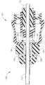
도 20-21은 캐뉼라(102)의 근위 단부에 제공될 수 있는 대표적인 대안의 래칭 특징부(1180)를 도시한다. 상기 래칭 특징부(1180)는 위에서 기술된 래칭 특징부(180)에 대한 대안의 단지 하나의 예시적인 예라는 것을 이해해야 한다. 또한, 래칭 특징부(1180)는 래칭 특징부(1180)가 일체로 형성될 수 있는 그 외의 다른 여러 타입의 구성들 중에 본 명세서에 기술된 임의의 삽입기(100, 400, 700) 내에 쉽게 일체로 구성될 수 있다는 것을 이해해야 한다. 이 예에서의 래칭 특징부(1180)는 그립(1181)과 버튼(1184)을 포함한다. 한 쌍의 래치(1182)가 버튼(1184)의 근위 측면으로부터 연장되며 버튼(1184)과 일체로 구성된다. 래치(1182)는 상기 래치(1182)를 허브 부재(80) 내에 선택적으로 보유하기 위해 허브 부재(80)의 상호보완적인 슬롯 내에 수용되는 외부를 향하는 돌출부(1186)를 포함한다. 그립(1181)과 버튼(1184) 사이에는 코일 스프링(1188)이 위치되며, 상기 코일 스프링은 버튼(1184)을 상부를 향하는 위치로 탄성적으로 편향시킨다. 코일 스프링(1188)은 버튼(1184)이 그립(1181)을 향해 눌러질 수 있게 하여 이에 상응하게 래치(1182)를 이동할 수 있게 한다. FIGS. 20-21 illustrate exemplary alternative latching features 1180 that may be provided at the proximal end of the
대표적인 사용 방법에서, 사용자는 캐뉼라(52)를 래칭 특징부(1180)를 통해 캐뉼라(102) 내로 삽입할 수 있다. 그립(1181)에 의해 형성된 원추형 램프(1190)는 캐뉼라(52)의 원위 단부를 캐뉼라(102) 내로 안내하는데 도움을 준다. 래치(1182)가 허브 부재(80)에 도달할 때, 코일 스프링(1188)은 돌출부(1186)가 이동되어 허브 부재(80)의 상호보완적인 슬롯과 결합될 수 있도록 압축될 수 있다. 그 뒤, 코일 스프링(1188)은, 추후에 버튼(1184)이 눌러져서 돌출부(1186)가 허브 부재(80)로부터 결합해제될 때까지, 돌출부(1186)가 허브 부재(80)와 결합한 상태로 유지하도록 팽창될 수 있다. 삽입기의 래칭 특징부에 일체로 구성될 수 있는 그 외의 다른 적절한 구성요소, 형상 및 작동기능들은 본 명세서에서 볼 때 당업자에게 자명할 것이다. In an exemplary method of use, a user may insert the
본 명세서에서 참조문헌으로서 인용되는 임의의 특허, 공보, 또는 그 외의 다른 문헌 재료들은 전체적으로 또는 부분적으로 본 명세서에서 인용된 재료가 기존의 정의, 설명, 또는 본 명세서에 설명된 그 외의 다른 기술 재료들과 상충되지 않는 범위에서 인용된다는 것을 이해해야 한다. 이런 방식으로, 그리고 필요한 정도까지, 본 명세서에서 명확하게 설명된 내용들은 참조문헌에 의해 본 명세서에 인용된 임의의 상충 재료들을 대신한다. 본 명세서에서 참조문헌으로 인용되지만 기존의 정의, 설명, 또는 본 명세서에서 설명된 그 외의 다른 기술 재료들과 상충하는 임의의 재료 또는 상기 재료의 일부분은 기존의 설명 재료와 인용된 재료 사이에서 어떠한 상충도 발생되지 않는 정도까지로만 인용될 것이다. Any patents, publications, or other literature materials cited herein as references may be incorporated herein by reference in their entirety or in part as if they are incorporated herein by reference in their entirety, Quot; is < / RTI > In this manner, and to the extent necessary, the disclosure explicitly described herein supersedes any conflicting materials cited herein by reference. Any material or a portion of such material, as referred to herein by reference, which conflicts with existing definitions, descriptions, or other technical materials described herein, Will be quoted only to the extent that it does not occur.
본 발명의 실시에들은 종래의 내시경 및 외과적 절개 수단 뿐만 아니라 로봇-보조 수술에도 적용된다. Embodiments of the present invention apply not only to conventional endoscopes and surgical incision devices, but also to robot-assisted surgery.
본 명세서에 기술된 장치들의 실시예들은 1회 사용 후에 폐기되도록 구성될 수 있거나, 또는 여러 번 사용될 수 있도록 구성될 수도 있다. 상기 실시예들은, 한 경우 또는 두 경우 모두, 1회 이상 사용한 후에 재사용하기 위해 원상회복될 수 있다(reconditioned). 이러한 원상회복 과정은 본 장치를 분해한 후에 특정 피스들을 세척하거나 교체하며, 그 뒤에, 재조립하는 단계들 중 임의의 조합을 포함할 수 있다. 특히, 본 장치의 실시예들은 분해될 수 있고, 본 장치의 임의의 개수를 가진 특정 피스 또는 부분들이 임의의 조합으로 선택적으로 교체되거나 제거될 수 있다. 특정 부분들이 세척되거나 및/또는 교체될 때에는, 본 장치의 실시예들은 원상회복 설비(reconditioning facility)에서, 또는 외과적 수술 직전에 수술 팀(surgical team)에 의해서 추후 사용을 위해 재조립될 수도 있다. 당업자들은 본 장치의 원상회복 과정이 분해, 세척/교체 및 재조립을 위해 다양한 기술을 이용할 수 있다는 것을 인해할 것이다. 이러한 기술의 사용방법과 그에 따른 원상회복된 장치는 모두 본 특허 출원의 범위 내에 있다. Embodiments of the devices described herein may be configured to be discarded after a single use, or may be configured to be used multiple times. The embodiments may be reconditioned to reuse after one or more uses in either or both cases. This reinstatement process may include any combination of the steps of cleaning or replacing certain pieces after disassembling the device, followed by reassembly. In particular, embodiments of the apparatus can be disassembled and specific pieces or portions having any number of the apparatus can be selectively replaced or removed in any combination. When specific parts are cleaned and / or replaced, embodiments of the device may be reassembled for later use in a reconditioning facility or by a surgical team immediately prior to surgical operation . Those skilled in the art will appreciate that the restoration process of the device can utilize a variety of techniques for disassembly, cleaning / replacement, and reassembly. The manner in which such techniques are used and the resulting restored devices are all within the scope of the present patent application.
단지 예로서, 본 명세서에 기술된 실시예들은 수술 전에 처리될 수도 있다. 우선, 새 기기 또는 사용된 기기를 수거하여 필요한 경우 세척될 수 있다. 그 후, 상기 기기는 살균될 수 있다. 한 살균 기술에서, 상기 기기는 플라스틱 또는 타이벡(TYVEK) 백과 같은 폐쇄 및 밀봉된 용기 내에 놓인다. 그 뒤, 상기 용기와 기기는 예컨대 감마 방사선, X-선, 또는 고에너지 전자와 같이 용기를 투과할 수 있는 방사선 영역 내에 위치될 수 있다. 방사선은 기기 위에 있고 용기 내에 있는 세균을 박멸할 수 있다. 그 뒤, 살균된 기기는 살균 용기 내에 보관될 수 있다. 밀봉된 용기는 의료 설비 내에서 개봉될 때까지 기기를 살균된 상태로 유지할 수 있다. 또한, 장치는 종래 기술에 알려져 있는 그 외의 다른 임의의 기술, 가령, 베타 또는 감마 방사선, 산화 에틸렌, 또는 스팀(steam)을 이용하여 살균될 수 있는데, 이들 기술에만 제한되지는 않는다. By way of example only, the embodiments described herein may be processed prior to surgery. First, new or used equipment can be collected and cleaned if necessary. The device can then be sterilized. In one sterilization technique, the device is placed in a closed and sealed container such as a plastic or TYVEK bag. The container and the device can then be located in a radiation area that is capable of penetrating the container, such as, for example, gamma radiation, X-rays, or high energy electrons. Radiation is on the device and can eradicate the bacteria in the container. The sterilized device can then be stored in a sterile container. The sealed container can maintain the device in a sanitized state until it is opened in the medical facility. In addition, the device may be sterilized using any other technology known in the art, such as beta or gamma radiation, ethylene oxide, or steam, but is not limited to these techniques.
이상으로, 본 발명의 다양한 실시예들을 도시하고 설명하였지만, 본 명세서에 기술된 방법 및 시스템의 추가적인 개선예들이 본 발명의 범위로부터 벗어나지 않고도 당업자에 의해 적절하게 변형됨으로써 구현될 수 있다. 이러한 잠재적인 변형예들 중 몇몇 변형예가 언급되었고, 그 외의 다른 변형예들도 당업자에게 자명할 것이다. 예를 들어, 위에서 논의된 예, 실시예, 기하학적 형상, 재료, 수치, 비율, 단계 등은 예시적인 것일 뿐 필수적인 것이 아니다. 따라서, 본 발명의 범위는 하기의 특허청구범위에 의해 고려되어야 하며, 명세서 및 도면에 도시되고 기술된 구성 및 작동 방법의 세부 내용에 제한되지 않는 것으로 이해하면 된다. Thus, while various embodiments of the present invention have been shown and described, further improvements in the methods and systems described herein may be implemented by appropriately modifying the invention by those skilled in the art without departing from the scope of the present invention. Several variations of these potential variations have been mentioned, and other variations will be apparent to those skilled in the art. For example, the above-mentioned examples, embodiments, geometries, materials, numerical values, ratios, steps, etc., are illustrative and not essential. It is therefore to be understood that the scope of the present invention is to be considered within the scope of the following claims and not limited to the details of the configuration and operation method shown and described in the specification and drawings.
Claims (12)
상기 삽입기는:
(i) 루멘을 형성하는 캐뉼라,
(ii) 날카로운 원위 팁,
(iii) 상기 팁에 대해 근위 위치에 형성된 가로 구멍으로, 상기 루멘과 유체 소통하는 상기 가로 구멍,
(iv) 근위 방향을 향하는 벽으로, 상기 근위 방향을 향하는 벽은 상기 날카로운 원위 팁에 대해 근위 위치에 배열되며, 상기 근위 방향을 향하는 벽은 상기 가로 구멍에 대해 원위 위치에 배열되고, 상기 루멘은 상기 근위 방향을 향하는 벽에서 끝을 이루는, 상기 근위 방향을 향하는 벽, 및
(v) 상기 루멘 내에 위치된 램프로, 상기 근위 방향을 향하는 벽을 향해 이어지는 상기 램프를 포함하는, 생검 시스템. In a biopsy system comprising an insertion device,
Said inserter comprising:
(i) a cannula forming a lumen,
(ii) a sharp distal tip,
(iii) a transverse hole formed in a proximal position relative to the tip, the transverse hole in fluid communication with the lumen,
(iv) a proximal wall, the proximal wall being arranged at a proximal position relative to the sharp distal tip, the proximal wall being arranged at a distal position relative to the transverse hole, and the lumen The proximal wall terminating at the proximal wall, and
(v) a lamp positioned within the lumen, the lamp leading to the proximal wall.
상기 삽입기는 상기 근위 방향을 향하는 벽과 상기 램프 사이에서 연장되는 쉘프 영역을 추가로 포함하고, 상기 램프는 상기 가로 구멍을 향하고, 상기 램프는 상기 삽입기 내로 삽입되는 물체를 상기 쉘프 영역까지 안내하도록 구성되고, 상기 쉘프 영역은 상기 물체를 상기 벽까지 안내하도록 구성되는 것을 특징으로 하는 생검 시스템. The method according to claim 1,
The inserter further includes a shelf region extending between the proximal wall and the ramp, the ramp facing the transverse hole, and the ramp directing an object inserted into the inserter to the shelf region And the shelf region is configured to guide the object to the wall.
상기 쉘프 영역은 상기 근위 방향을 향하는 벽에 대해 실질적으로 수직으로 배열되며, 상기 쉘프 영역은 상기 램프에 대해서 비스듬하게 배열되는 것을 특징으로 하는 생검 시스템. 3. The method of claim 2,
Wherein the shelf regions are arranged substantially perpendicular to the wall facing the proximal direction and the shelf regions are arranged at an angle to the ramp.
상기 생검 시스템은 생검 장치를 추가로 포함하며, 상기 생검 장치는 뭉특한 팁에서 끝을 이루는 뭉특한 팁 부분을 가진 바늘을 포함하고, 상기 바늘은 상기 삽입기의 캐뉼라의 루멘 내에 삽입될 수 있으며, 상기 뭉특한 팁은 상기 바늘이 상기 삽입기의 캐뉼라의 루멘 내에 삽입될 때 상기 삽입기의 근위 방향을 향하는 벽과 접하도록 구성되는 것을 특징으로 하는 생검 시스템. The method according to claim 1,
Wherein the biopsy system further comprises a biopsy device including a needle having a distinctive tip portion that terminates at a coarse tip that can be inserted into the lumen of the cannula of the inserter, Wherein the coarse tip is configured to abut a wall facing the proximal direction of the inserter when the needle is inserted into the lumen of the cannula of the inserter.
상기 바늘은 상기 뭉특한 팁에 대해 근위 위치에 형성된 가로 구멍을 추가로 포함하며, 상기 바늘의 가로 구멍은 상기 바늘이 상기 삽입기의 캐뉼라의 루멘 내에 삽입될 때 상기 삽입기의 가로 구멍과 실질적으로 정렬되도록 구성되는 것을 특징으로 하는 생검 시스템. 5. The method of claim 4,
Wherein the needle further comprises a transverse hole formed in a proximal position relative to the coarse tip, the transverse hole of the needle being substantially coaxial with the transverse hole of the inserter when the needle is inserted into the lumen of the canula of the inserter Wherein the biopsy system is configured to be aligned.
상기 바늘은 상기 뭉특한 팁의 세로 위치에 대해 근위 위치에 배열된 세로 위치에서 끝을 이루는 원위 단부를 가진 하측 부분을 추가로 포함하는 것을 특징으로 하는 생검 시스템. 5. The method of claim 4,
Wherein the needle further comprises a lower portion having a distal end terminating in a longitudinal position arranged in a proximal position relative to a longitudinal position of the coarse tip.
상기 하측 부분의 원위 단부는 상기 바늘이 상기 삽입기의 캐뉼라의 루멘 내에 삽입될 때 상기 램프에 대해 근위 위치로 이격되는 것을 특징으로 하는 생검 시스템. The method according to claim 6,
Wherein the distal end of the lower portion is spaced from the proximal position relative to the ramp when the needle is inserted into the lumen of the cannula of the inserter.
상기 생검 시스템은 생검 부위 마커 어플라이어를 추가로 포함하고, 상기 생검 부위 마커 어플라이어는 캐뉼라를 포함하며, 상기 마커 어플라이어의 캐뉼라는 상기 삽입기의 캐뉼라의 루멘 내에 삽입될 수 있고, 상기 생검 부위 마커 어플라이어는 생검 부위에서 생검 부위 마커를 전개시키도록 작동될 수 있는 것을 특징으로 하는 생검 시스템. The method according to claim 1,
Wherein the biopsy system further comprises a biopsy site marker applicator, wherein the biopsy site marker applicator comprises a cannula, the cannula of the marker applicator being insertable into a lumen of a cannula of the inserter, Wherein the marker applicator is operable to deploy a biopsy site marker at a biopsy site.
상기 생검 부위 마커 어플라이어는 폐쇄된 원위 단부를 추가로 포함하고, 상기 폐쇄된 원위 단부는 상기 생검 부위 마커 어플라이어의 캐뉼라가 상기 삽입기의 캐뉼라의 루멘 내에 삽입될 때 상기 삽입기의 근위 방향을 향하는 벽과 접하도록 구성되는 것을 특징으로 하는 생검 시스템. 9. The method of claim 8,
Wherein the biopsy site marker applicator further comprises a closed distal end wherein the closed distal end is positioned such that when the cannula of the biopsy site marker applicator is inserted into the lumen of the cannula of the introducer, Wherein the biocompatible material is configured to contact a wall facing the wall.
상기 생검 부위 마커 어플라이어는 상기 폐쇄된 원위 단부에 대해 근위 위치로 이격된 가로 구멍을 추가로 포함하고, 상기 생검 부위 마커 어플라이어의 가로 구멍은 상기 생검 부위 마커 어플라이어의 캐뉼라가 상기 삽입기의 캐뉼라의 루멘 내에 삽입될 때 상기 삽입기의 가로 구멍과 실질적으로 정렬되도록 구성되는 것을 특징으로 하는 생검 시스템. 10. The method of claim 9,
Wherein the biopsy site marker applicator further comprises a transverse hole spaced proximally relative to the closed distal end, the transverse hole of the biopsy site marker applicator having a cannula of the biopsy site marker applicator, Wherein the biopsy system is configured to be substantially aligned with the transverse holes of the inserter when inserted into the lumen of the cannula.
상기 생검 부위 마커 어플라이어의 상기 폐쇄된 원위 단부는 상기 삽입기의 캐뉼라의 루멘을 통해 상기 생검 부위 마커 어플라이어를 원위 방향으로 삽입하는 동안 상기 근위 방향을 향하는 벽에 도달하도록 상기 삽입기의 램프와 결합하여 램프를 따라 이동하도록 구성되는 것을 특징으로 하는 생검 시스템. 10. The method of claim 9,
Wherein said closed distal end of said biopsy site marker applicator is adapted to receive said biopsy site marker applicator through a lumen of a cannula of said inserter, And to move along the ramp.
상기 삽입기는 상기 근위 방향을 향하는 벽과 상기 램프 사이에 연장되는 쉘프 영역을 추가로 포함하고, 상기 생검 부위 마커 어플라이어의 폐쇄된 원위 단부는 상기 생검 부위 마커 어플라이어의 폐쇄된 원위 단부가 상기 삽입기의 근위 방향을 향하는 벽에 접할 때 상기 삽입기의 캐뉼라의 내부 측벽 영역과 상기 쉘프 사이에서 수직으로 위치되는 것을 특징으로 하는 생검 시스템.
12. The method of claim 11,
Wherein the inserter further comprises a shelf region extending between the proximal wall and the ramp, the closed distal end of the biopsy site marker applicator having a closed distal end of the biopsy site marker applicator, Is positioned vertically between the inner sidewall region of the cannula of the inserter and the shelf when abutting against a wall facing the proximal direction of the vessel.
Applications Claiming Priority (3)
| Application Number | Priority Date | Filing Date | Title |
|---|---|---|---|
| US13/166,918 US9414816B2 (en) | 2011-06-23 | 2011-06-23 | Introducer for biopsy device |
| US13/166,918 | 2011-06-23 | ||
| PCT/US2012/041188 WO2012177398A2 (en) | 2011-06-23 | 2012-06-07 | Introducer for biopsy device |
Related Parent Applications (1)
| Application Number | Title | Priority Date | Filing Date |
|---|---|---|---|
| KR1020147000486A Division KR101851924B1 (en) | 2011-06-23 | 2012-06-07 | Introducer for biopsy device |
Publications (2)
| Publication Number | Publication Date |
|---|---|
| KR20180041254A true KR20180041254A (en) | 2018-04-23 |
| KR102049850B1 KR102049850B1 (en) | 2019-11-28 |
Family
ID=47362496
Family Applications (2)
| Application Number | Title | Priority Date | Filing Date |
|---|---|---|---|
| KR1020187010242A Expired - Fee Related KR102049850B1 (en) | 2011-06-23 | 2012-06-07 | Introducer for biopsy device |
| KR1020147000486A Active KR101851924B1 (en) | 2011-06-23 | 2012-06-07 | Introducer for biopsy device |
Family Applications After (1)
| Application Number | Title | Priority Date | Filing Date |
|---|---|---|---|
| KR1020147000486A Active KR101851924B1 (en) | 2011-06-23 | 2012-06-07 | Introducer for biopsy device |
Country Status (7)
| Country | Link |
|---|---|
| US (2) | US9414816B2 (en) |
| EP (2) | EP2989994B1 (en) |
| JP (2) | JP5976794B2 (en) |
| KR (2) | KR102049850B1 (en) |
| CN (2) | CN103619264B (en) |
| CA (1) | CA2837825A1 (en) |
| WO (1) | WO2012177398A2 (en) |
Families Citing this family (34)
| Publication number | Priority date | Publication date | Assignee | Title |
|---|---|---|---|---|
| US9414816B2 (en) | 2011-06-23 | 2016-08-16 | Devicor Medical Products, Inc. | Introducer for biopsy device |
| WO2014140882A2 (en) | 2013-03-14 | 2014-09-18 | The Governing Council Of The University Of Toronto | Scaffolded peptidic libraries and methods of making and screening the same |
| CN105073022A (en) * | 2013-03-15 | 2015-11-18 | 德维克医疗产品公司 | Biopsy site marker releaser |
| KR101863804B1 (en) * | 2013-07-19 | 2018-06-04 | 데비코어 메디컬 프로덕츠, 인코포레이티드 | Biopsy device targeting features |
| WO2015081309A1 (en) | 2013-11-26 | 2015-06-04 | Hologic, Inc. | Biopsy device arming mechanism |
| KR101649713B1 (en) * | 2014-04-10 | 2016-08-19 | 주식회사 메디칼파크 | Biopsy device and system |
| CA2947284C (en) * | 2014-05-01 | 2019-01-29 | Devicor Medical Products, Inc. | Introducer for biopsy device |
| CN106659375A (en) | 2014-05-13 | 2017-05-10 | Vycor医学有限责任公司 | Guidance system mounts for surgical introducers |
| US9993232B2 (en) | 2014-05-22 | 2018-06-12 | Andrew N. Ellingson | Biopsy with marker device and method |
| WO2016009366A1 (en) | 2014-07-16 | 2016-01-21 | Koninklijke Philips N.V. | Ultrasound tracking apparatus for disposable biopsy needles |
| US10646208B2 (en) | 2015-05-06 | 2020-05-12 | Devicor Medical Products, Inc. | Marker delivery device for use with MRI breast biopsy system |
| WO2016179145A1 (en) * | 2015-05-06 | 2016-11-10 | Devicor Medical Products, Inc. | Mri guided breast biopsy targeting assembly with obturator overshoot feature |
| WO2017035213A1 (en) * | 2015-08-24 | 2017-03-02 | University Of Louisville Research Foundation, Inc. | Biopsy sampling device |
| US10478553B2 (en) * | 2016-03-09 | 2019-11-19 | Orbit Biomedical Limited | Apparatus for subretinal administration of therapeutic agent via a curved needle |
| US10695085B2 (en) * | 2016-08-11 | 2020-06-30 | Biosense Webster (Israel) Ltd. | Turbine-driven rotary sinuplasty cutter |
| US10376258B2 (en) * | 2016-11-07 | 2019-08-13 | Vycor Medical, Inc. | Surgical introducer with guidance system receptacle |
| US12178469B2 (en) | 2016-11-07 | 2024-12-31 | Vycor Medical Inc. | Surgical introducer with guidance system receptacle |
| US10543016B2 (en) | 2016-11-07 | 2020-01-28 | Vycor Medical, Inc. | Surgical introducer with guidance system receptacle |
| WO2018106789A1 (en) * | 2016-12-07 | 2018-06-14 | Boston Scientific Scimed, Inc. | Systems for real-time biopsy needle and target tissue visualization |
| CN110267600B (en) * | 2017-02-06 | 2022-12-20 | 设备与设计有限责任公司 | Systems, methods, and devices for integrated tissue sampling and tissue marker placement |
| US20180289467A1 (en) * | 2017-04-05 | 2018-10-11 | Ernesto Andrade | Dispensing device, kit, and method for tissue augmentation |
| US20190029758A1 (en) * | 2017-05-22 | 2019-01-31 | Devicor Medical Products, Inc. | Mri targeting set with improved targeting sleeve |
| EP3678560A4 (en) | 2017-09-09 | 2021-05-19 | June Medical IP, LLC | Passive safety intraosseous device |
| US20190314059A1 (en) | 2017-09-09 | 2019-10-17 | Billie Coppedge | Cannula with recessed hub structure |
| CN109806029B (en) * | 2017-11-21 | 2021-02-09 | 杭州德晋医疗科技有限公司 | Artificial chordae tendineae implanting system with negative pressure device |
| CN109833117B (en) * | 2017-11-28 | 2020-12-25 | 杭州德晋医疗科技有限公司 | Bilateral artificial chordae tendineae implantation system |
| EP3781042B1 (en) | 2018-04-18 | 2025-03-05 | C. R. Bard, Inc. | Dual lumen coaxial introducer having integrated tissue marker delivery |
| EP3597112A1 (en) * | 2018-07-17 | 2020-01-22 | Erbe Elektromedizin GmbH | Biopsy material recovery device |
| WO2020028303A1 (en) * | 2018-07-31 | 2020-02-06 | Devicor Medical Products, Inc. | Core needle biopsy device for collecting multiple samples in a single insertion |
| USD933837S1 (en) * | 2018-08-31 | 2021-10-19 | Devicor Medical Products, Inc. | Probe body |
| CN113164168B (en) * | 2018-12-10 | 2024-04-12 | Devicor医疗产业收购公司 | Biopsy system with end deployment needle |
| BR112021016646A2 (en) * | 2019-03-22 | 2021-11-03 | Bard Inc C R | Sealant delivery apparatus and system and method for preparing the same for use in a lung procedure |
| EP3973888A1 (en) * | 2020-09-23 | 2022-03-30 | Xaga Surgical AB | Improved biopsy arrangement |
| CN114699114A (en) * | 2022-03-30 | 2022-07-05 | 上海集粹医疗科技中心 | A soft tissue cutting biopsy gun for endoscopy or image guidance |
Citations (2)
| Publication number | Priority date | Publication date | Assignee | Title |
|---|---|---|---|---|
| JP2005288175A (en) * | 2004-03-31 | 2005-10-20 | Ethicon Endo Surgery Inc | Marker device and method for arranging marker using surgical biopsy device |
| US20080015429A1 (en) * | 2004-05-21 | 2008-01-17 | Tsonton Mark T | Mri biopsy device |
Family Cites Families (111)
| Publication number | Priority date | Publication date | Assignee | Title |
|---|---|---|---|---|
| JPS646915U (en) * | 1987-07-02 | 1989-01-17 | ||
| JPH0641535Y2 (en) * | 1988-09-22 | 1994-11-02 | 富士写真光機株式会社 | Internal diagnosis / treatment device |
| US5104378A (en) * | 1989-10-13 | 1992-04-14 | Habley Medical Technology Corporation | Syringe having means for retracting, canting and destroying a needle cannula |
| US5320110A (en) * | 1991-10-29 | 1994-06-14 | Wang Ko P | Pleural biopsy syringe-needles |
| US5595186A (en) * | 1992-04-06 | 1997-01-21 | Alan I. Rubinstein | Bone marrow biopsy needle |
| US5209739A (en) * | 1992-06-23 | 1993-05-11 | Leon Talalay | Hypodermic needle |
| US5257632A (en) | 1992-09-09 | 1993-11-02 | Symbiosis Corporation | Coaxial bone marrow biopsy coring and aspirating needle assembly and method of use thereof |
| US5263937A (en) * | 1993-02-11 | 1993-11-23 | Shipp John I | Trocar with profile to reduce insertion force |
| US5301684A (en) * | 1993-04-27 | 1994-04-12 | International Electronic Technology Corp. | Biopsy needle |
| CN1057905C (en) | 1993-06-16 | 2000-11-01 | 洛马林达大学医学中心 | Trocar facilitator for endoscopic surgery |
| US5364365A (en) * | 1993-08-30 | 1994-11-15 | Surgin Surgical Instrumentation, Inc. | Safety device for laparoscopic instruments |
| US5526822A (en) | 1994-03-24 | 1996-06-18 | Biopsys Medical, Inc. | Method and apparatus for automated biopsy and collection of soft tissue |
| US5649547A (en) * | 1994-03-24 | 1997-07-22 | Biopsys Medical, Inc. | Methods and devices for automated biopsy and collection of soft tissue |
| CA2199864C (en) | 1994-09-16 | 2006-06-20 | Seth A. Foerster | Methods and devices for defining and marking tissue |
| AU4763296A (en) * | 1995-02-03 | 1996-08-21 | Inbae Yoon | Cannula with distal end valve |
| JP4344016B2 (en) * | 1995-03-30 | 2009-10-14 | テルモ株式会社 | Trocar tube, trocar tube assembly and catheter insertion instrument |
| US5797927A (en) * | 1995-09-22 | 1998-08-25 | Yoon; Inbae | Combined tissue clamping and suturing instrument |
| CA2184958A1 (en) * | 1995-09-22 | 1997-03-23 | John S. Gentelia | Improved trocar-cannulla device |
| US5709671A (en) * | 1995-10-16 | 1998-01-20 | Ethicon Endo-Surgery, Inc. | Trocar having an improved tip configuration |
| US5800389A (en) | 1996-02-09 | 1998-09-01 | Emx, Inc. | Biopsy device |
| US6203524B1 (en) * | 1997-02-10 | 2001-03-20 | Emx, Inc. | Surgical and pharmaceutical site access guide and methods |
| US6030364A (en) * | 1997-10-03 | 2000-02-29 | Boston Scientific Corporation | Apparatus and method for percutaneous placement of gastro-intestinal tubes |
| US6270464B1 (en) * | 1998-06-22 | 2001-08-07 | Artemis Medical, Inc. | Biopsy localization method and device |
| US6347241B2 (en) | 1999-02-02 | 2002-02-12 | Senorx, Inc. | Ultrasonic and x-ray detectable biopsy site marker and apparatus for applying it |
| US6220248B1 (en) * | 1998-10-21 | 2001-04-24 | Ethicon Endo-Surgery, Inc. | Method for implanting a biopsy marker |
| US6371904B1 (en) | 1998-12-24 | 2002-04-16 | Vivant Medical, Inc. | Subcutaneous cavity marking device and method |
| US6725083B1 (en) | 1999-02-02 | 2004-04-20 | Senorx, Inc. | Tissue site markers for in VIVO imaging |
| JP4638051B2 (en) * | 1999-03-19 | 2011-02-23 | ヴァイダケア、コーパレイシャン | Biopsy needle |
| US6086544A (en) | 1999-03-31 | 2000-07-11 | Ethicon Endo-Surgery, Inc. | Control apparatus for an automated surgical biopsy device |
| US6234177B1 (en) | 1999-08-12 | 2001-05-22 | Thomas Barsch | Apparatus and method for deploying an expandable biopsy marker |
| US6436119B1 (en) * | 1999-09-30 | 2002-08-20 | Raymedica, Inc. | Adjustable surgical dilator |
| US6277083B1 (en) * | 1999-12-27 | 2001-08-21 | Neothermia Corporation | Minimally invasive intact recovery of tissue |
| US6602203B2 (en) | 2000-10-13 | 2003-08-05 | Ethicon Endo-Surgery, Inc. | Remote thumbwheel for a surgical biopsy device |
| AU2002239290A1 (en) * | 2000-11-20 | 2002-06-03 | Senorx, Inc. | Tissue site markers for in vivo imaging |
| EP1385433B1 (en) * | 2001-05-11 | 2008-08-06 | Applied Medical Resources Corporation | Traction trocar apparatus and method |
| US6752769B2 (en) * | 2001-06-26 | 2004-06-22 | Health Research, Inc. | Core bite biopsy needle |
| US6626849B2 (en) | 2001-11-01 | 2003-09-30 | Ethicon Endo-Surgery, Inc. | MRI compatible surgical biopsy device |
| CA2494377C (en) | 2002-08-01 | 2012-09-25 | James E. Selis | Biopsy devices and methods |
| US8105345B2 (en) * | 2002-10-04 | 2012-01-31 | Medtronic, Inc. | Anastomosis apparatus and methods |
| US20080161720A1 (en) * | 2002-10-07 | 2008-07-03 | Nicoson Zachary R | Registration system |
| US7056329B2 (en) * | 2002-10-23 | 2006-06-06 | Intellimed Surgical Solutions, Llc | Laparoscopic direct vision dissecting port |
| US6994712B1 (en) * | 2002-11-12 | 2006-02-07 | Biopsy Sciences, Llc | Bioabsorbable marker having external anchoring means |
| US20050159676A1 (en) * | 2003-08-13 | 2005-07-21 | Taylor James D. | Targeted biopsy delivery system |
| US8394114B2 (en) * | 2003-09-26 | 2013-03-12 | Medtronic, Inc. | Surgical connection apparatus and methods |
| WO2005037106A2 (en) * | 2003-10-14 | 2005-04-28 | Suros Surgical Systems, Inc. | Vacuum assisted biopsy needle set |
| US8357103B2 (en) * | 2003-10-14 | 2013-01-22 | Suros Surgical Systems, Inc. | Vacuum assisted biopsy needle set |
| US20050203419A1 (en) | 2004-02-24 | 2005-09-15 | Nirmala Ramanujam | Side-firing probe for performing optical spectroscopy during core needle biopsy |
| CN101984920B (en) * | 2004-04-05 | 2012-09-26 | Hi-Lex株式会社 | Medical devices for bone marrow harvesting |
| EP1759638B1 (en) | 2004-05-11 | 2009-04-08 | Inrad, Inc. | Core biopsy device |
| US20080281226A1 (en) * | 2004-05-11 | 2008-11-13 | Inrad, Inc. | Core Biopsy Device with Specimen Length Adjustment |
| CA2506961C (en) * | 2004-05-11 | 2013-05-07 | Inrad, Inc. | Core biopsy device |
| US9638770B2 (en) * | 2004-05-21 | 2017-05-02 | Devicor Medical Products, Inc. | MRI biopsy apparatus incorporating an imageable penetrating portion |
| EP1761174B1 (en) * | 2004-05-21 | 2009-10-07 | Ethicon Endo-Surgery, Inc. | Mri biopsy apparatus incorporating an imagable penetrating portion |
| US20060074345A1 (en) | 2004-09-29 | 2006-04-06 | Hibner John A | Biopsy apparatus and method |
| US20060144548A1 (en) * | 2004-12-30 | 2006-07-06 | Beckman Andrew T | Method of manufacturing a needle assembly for use with a biopsy device |
| US20060200041A1 (en) * | 2005-03-04 | 2006-09-07 | Ethicon Endo-Surgery, Inc. | Biopsy device incorporating an adjustable probe sleeve |
| DE102005021470A1 (en) * | 2005-05-10 | 2006-11-16 | Tracoe Medical Gmbh | Introducer for percutaneous tracheostomy |
| US7662109B2 (en) * | 2006-02-01 | 2010-02-16 | Ethicon Endo-Surgery, Inc. | Biopsy device with replaceable probe incorporating static vacuum source dual valve sample stacking retrieval and saline flush |
| CN101272819B (en) | 2005-09-16 | 2010-09-29 | 西格弗里德·里克 | Medical instrument |
| US7815571B2 (en) * | 2006-04-20 | 2010-10-19 | Gynesonics, Inc. | Rigid delivery systems having inclined ultrasound and needle |
| US8187203B2 (en) * | 2006-02-24 | 2012-05-29 | Mcclellan W Thomas | Biopsy needle system, biopsy needle and method for obtaining a tissue biopsy specimen |
| US7507210B2 (en) | 2006-05-01 | 2009-03-24 | Ethicon Endo-Surgery, Inc. | Biopsy cannula adjustable depth stop |
| WO2008001385A2 (en) * | 2006-06-29 | 2008-01-03 | Depuy Spine, Inc. | Integrated bone biopsy and therapy apparatus |
| WO2008020896A1 (en) * | 2006-08-07 | 2008-02-21 | Strathmore Industries Inc. | Bone tamp apparatus and method |
| CN101534740B (en) * | 2006-09-12 | 2012-06-20 | 维达保健公司 | Medical procedure tray with intraosseous devices |
| US7914463B2 (en) * | 2006-10-23 | 2011-03-29 | Clipius Technologies, Inc. | Double core biopsy instrumentation kit |
| EP3714798A3 (en) * | 2006-10-24 | 2020-12-16 | C. R. Bard, Inc. | Large sample low aspect ratio biopsy needle |
| US9345457B2 (en) | 2006-12-13 | 2016-05-24 | Devicor Medical Products, Inc. | Presentation of biopsy sample by biopsy device |
| US8702623B2 (en) | 2008-12-18 | 2014-04-22 | Devicor Medical Products, Inc. | Biopsy device with discrete tissue chambers |
| US8398566B2 (en) * | 2007-05-11 | 2013-03-19 | Alec S. Goldenberg | Biopsy needles |
| US20090131790A1 (en) * | 2007-05-15 | 2009-05-21 | Gynesonics, Inc. | Systems and methods for deploying echogenic components in ultrasonic imaging fields |
| CN101053508A (en) | 2007-05-21 | 2007-10-17 | 张亚平 | Disposable self-destructing type multi-functional light-conducting examining device and its application |
| US7722550B2 (en) * | 2007-07-26 | 2010-05-25 | Mcclellan W Thomas | Biopsy needle with different cross-sectional shapes and associated trap doors |
| US7854706B2 (en) | 2007-12-27 | 2010-12-21 | Devicor Medical Products, Inc. | Clutch and valving system for tetherless biopsy device |
| US20090209854A1 (en) | 2008-02-19 | 2009-08-20 | Parihar Shailendra K | Biopsy method |
| US8068895B2 (en) * | 2008-02-25 | 2011-11-29 | Devicor Medical Products, Inc. | Biopsy site marker deployment instrument |
| US8079964B2 (en) | 2008-02-25 | 2011-12-20 | Devicor Medical Products, Inc. | Method and apparatus for inserting biopsy site marker in marker body |
| US20090247900A1 (en) * | 2008-03-25 | 2009-10-01 | Brian Zimmer | Push button adjustable spacer |
| US8864681B2 (en) * | 2008-04-23 | 2014-10-21 | Devicor Medical Products, Inc. | Biopsy devices |
| US8532748B2 (en) | 2008-04-23 | 2013-09-10 | Devicor Medical Products, Inc. | Devices useful in imaging |
| US20090270726A1 (en) * | 2008-04-23 | 2009-10-29 | Leimbach Jessica P | Methods For Imaging |
| US20090270892A1 (en) * | 2008-04-25 | 2009-10-29 | Greg Arcenio | Steerable medical device for tissue disruption |
| US8050742B2 (en) * | 2008-07-30 | 2011-11-01 | Devicor Medical Products, Inc. | Biopsy device |
| US8532747B2 (en) | 2008-08-22 | 2013-09-10 | Devicor Medical Products, Inc. | Biopsy marker delivery device |
| US20100049085A1 (en) * | 2008-08-22 | 2010-02-25 | Nock Andrew P | Method of making a biopsy marker delivery device |
| CN107260231A (en) * | 2008-10-20 | 2017-10-20 | 脊柱诊察公司 | Retractor cannula system for entering and watching backbone |
| US20100114031A1 (en) * | 2008-11-05 | 2010-05-06 | Jarial Inderjeet S | Introducer localization assemblies |
| EP3187219B2 (en) * | 2008-12-02 | 2026-03-04 | Allergan, Inc. | Injection device |
| US20100152610A1 (en) | 2008-12-16 | 2010-06-17 | Parihar Shailendra K | Hand Actuated Tetherless Biopsy Device with Pistol Grip |
| US20100160822A1 (en) * | 2008-12-18 | 2010-06-24 | Parihar Shailendra K | Biopsy Device with Detachable Needle |
| US20100160819A1 (en) | 2008-12-18 | 2010-06-24 | Parihar Shailendra K | Biopsy Device with Central Thumbwheel |
| ES2456342T3 (en) | 2009-02-06 | 2014-04-22 | Vistamed R & D Ltd. | Catheter introducer |
| US8343035B2 (en) * | 2009-04-20 | 2013-01-01 | Spine View, Inc. | Dilator with direct visualization |
| US8206316B2 (en) | 2009-06-12 | 2012-06-26 | Devicor Medical Products, Inc. | Tetherless biopsy device with reusable portion |
| US9498192B2 (en) * | 2009-08-03 | 2016-11-22 | Dune Medical Devices Ltd. | Surgical tool |
| US8277394B2 (en) | 2009-08-18 | 2012-10-02 | Devicor Medical Products, Inc. | Multi-button biopsy device |
| US20110071423A1 (en) | 2009-09-21 | 2011-03-24 | Speeg Trevor W V | Flexible biopsy marker delivery device |
| US8371443B2 (en) | 2009-09-22 | 2013-02-12 | Devicor Medical Products, Inc. | Biopsy marker delivery device |
| US8529465B2 (en) * | 2009-09-24 | 2013-09-10 | Devicor Medical Products, Inc. | Biopsy marker delivery devices and methods |
| US20110071391A1 (en) | 2009-09-24 | 2011-03-24 | Speeg Trevor W V | Biopsy marker delivery device with positioning component |
| US20110092850A1 (en) * | 2009-10-16 | 2011-04-21 | Kulkarni Abhijit G | MRI Biopsy Targeting Guide with Rotational Lock |
| US8241299B2 (en) * | 2009-10-22 | 2012-08-14 | Devicor Medical Products, Inc. | Biopsy marker delivery configured to retain marker prior to intended deployment |
| US8376957B2 (en) | 2010-02-22 | 2013-02-19 | Devicor Medical Products, Inc. | Biopsy device with auxiliary vacuum source |
| US20110208090A1 (en) * | 2010-02-22 | 2011-08-25 | Parihar Shailendra K | Spring Loaded Biopsy Device |
| US8641641B2 (en) * | 2010-05-11 | 2014-02-04 | Ethicon Endo-Surgery, Inc. | Instrument for applying therapeutic cells, with proximal portion for processing therapeutic cells |
| US20120022397A1 (en) * | 2010-07-22 | 2012-01-26 | Jarial Inderjeet S | Needle Set for a Biopsy Device and Related Method |
| US20120022399A1 (en) * | 2010-07-26 | 2012-01-26 | Mumaw Daniel J | Biopsy Device with Integral Needle Tip Protector |
| US20120022400A1 (en) * | 2010-07-26 | 2012-01-26 | Mumaw Daniel J | Biopsy Device with Detachable Needle Tip Protector |
| US20120059247A1 (en) | 2010-09-03 | 2012-03-08 | Speeg Trevor W V | Echogenic needle for biopsy device |
| US8764680B2 (en) | 2010-11-01 | 2014-07-01 | Devicor Medical Products, Inc. | Handheld biopsy device with needle firing |
| US9414816B2 (en) | 2011-06-23 | 2016-08-16 | Devicor Medical Products, Inc. | Introducer for biopsy device |
-
2011
- 2011-06-23 US US13/166,918 patent/US9414816B2/en active Active
-
2012
- 2012-06-07 JP JP2014516996A patent/JP5976794B2/en active Active
- 2012-06-07 EP EP15187481.5A patent/EP2989994B1/en active Active
- 2012-06-07 CN CN201280029965.2A patent/CN103619264B/en active Active
- 2012-06-07 KR KR1020187010242A patent/KR102049850B1/en not_active Expired - Fee Related
- 2012-06-07 WO PCT/US2012/041188 patent/WO2012177398A2/en not_active Ceased
- 2012-06-07 KR KR1020147000486A patent/KR101851924B1/en active Active
- 2012-06-07 CA CA2837825A patent/CA2837825A1/en not_active Abandoned
- 2012-06-07 CN CN201610201548.1A patent/CN105662486B/en not_active Expired - Fee Related
- 2012-06-07 EP EP12803348.7A patent/EP2723243A4/en not_active Withdrawn
-
2016
- 2016-03-24 JP JP2016059686A patent/JP6243461B2/en not_active Expired - Fee Related
- 2016-07-19 US US15/214,086 patent/US10258316B2/en active Active
Patent Citations (2)
| Publication number | Priority date | Publication date | Assignee | Title |
|---|---|---|---|---|
| JP2005288175A (en) * | 2004-03-31 | 2005-10-20 | Ethicon Endo Surgery Inc | Marker device and method for arranging marker using surgical biopsy device |
| US20080015429A1 (en) * | 2004-05-21 | 2008-01-17 | Tsonton Mark T | Mri biopsy device |
Also Published As
| Publication number | Publication date |
|---|---|
| JP6243461B2 (en) | 2017-12-06 |
| HK1222111A1 (en) | 2017-06-23 |
| EP2989994A1 (en) | 2016-03-02 |
| WO2012177398A2 (en) | 2012-12-27 |
| CN103619264B (en) | 2016-04-20 |
| US9414816B2 (en) | 2016-08-16 |
| WO2012177398A3 (en) | 2013-02-21 |
| KR20140039042A (en) | 2014-03-31 |
| JP2016152930A (en) | 2016-08-25 |
| US10258316B2 (en) | 2019-04-16 |
| CN105662486A (en) | 2016-06-15 |
| US20120330186A1 (en) | 2012-12-27 |
| JP2014519950A (en) | 2014-08-21 |
| KR102049850B1 (en) | 2019-11-28 |
| EP2723243A2 (en) | 2014-04-30 |
| US20160324509A1 (en) | 2016-11-10 |
| EP2723243A4 (en) | 2015-04-01 |
| CN105662486B (en) | 2018-12-07 |
| EP2989994B1 (en) | 2019-05-29 |
| CN103619264A (en) | 2014-03-05 |
| JP5976794B2 (en) | 2016-08-24 |
| CA2837825A1 (en) | 2012-12-27 |
| KR101851924B1 (en) | 2018-04-26 |
Similar Documents
| Publication | Publication Date | Title |
|---|---|---|
| KR101851924B1 (en) | Introducer for biopsy device | |
| US8529465B2 (en) | Biopsy marker delivery devices and methods | |
| EP2996570B1 (en) | Biopsy site marker applier | |
| US8371443B2 (en) | Biopsy marker delivery device | |
| JP6538078B2 (en) | Introducer for biopsy device | |
| WO2016179147A1 (en) | Marker delivery device for use with mri breast biopsy system | |
| HK1222111B (en) | Introducer for biopsy device | |
| HK1222783B (en) | Biopsy site marker applier |
Legal Events
| Date | Code | Title | Description |
|---|---|---|---|
| A107 | Divisional application of patent | ||
| PA0104 | Divisional application for international application |
St.27 status event code: A-0-1-A10-A18-div-PA0104 St.27 status event code: A-0-1-A10-A16-div-PA0104 |
|
| PG1501 | Laying open of application |
St.27 status event code: A-1-1-Q10-Q12-nap-PG1501 |
|
| A201 | Request for examination | ||
| PA0201 | Request for examination |
St.27 status event code: A-1-2-D10-D11-exm-PA0201 |
|
| R17-X000 | Change to representative recorded |
St.27 status event code: A-3-3-R10-R17-oth-X000 |
|
| D13-X000 | Search requested |
St.27 status event code: A-1-2-D10-D13-srh-X000 |
|
| D14-X000 | Search report completed |
St.27 status event code: A-1-2-D10-D14-srh-X000 |
|
| E902 | Notification of reason for refusal | ||
| PE0902 | Notice of grounds for rejection |
St.27 status event code: A-1-2-D10-D21-exm-PE0902 |
|
| E13-X000 | Pre-grant limitation requested |
St.27 status event code: A-2-3-E10-E13-lim-X000 |
|
| P11-X000 | Amendment of application requested |
St.27 status event code: A-2-2-P10-P11-nap-X000 |
|
| P13-X000 | Application amended |
St.27 status event code: A-2-2-P10-P13-nap-X000 |
|
| E90F | Notification of reason for final refusal | ||
| PE0902 | Notice of grounds for rejection |
St.27 status event code: A-1-2-D10-D21-exm-PE0902 |
|
| P11-X000 | Amendment of application requested |
St.27 status event code: A-2-2-P10-P11-nap-X000 |
|
| P13-X000 | Application amended |
St.27 status event code: A-2-2-P10-P13-nap-X000 |
|
| E701 | Decision to grant or registration of patent right | ||
| PE0701 | Decision of registration |
St.27 status event code: A-1-2-D10-D22-exm-PE0701 |
|
| GRNT | Written decision to grant | ||
| PR0701 | Registration of establishment |
St.27 status event code: A-2-4-F10-F11-exm-PR0701 |
|
| PR1002 | Payment of registration fee |
St.27 status event code: A-2-2-U10-U12-oth-PR1002 Fee payment year number: 1 |
|
| PG1601 | Publication of registration |
St.27 status event code: A-4-4-Q10-Q13-nap-PG1601 |
|
| R18-X000 | Changes to party contact information recorded |
St.27 status event code: A-5-5-R10-R18-oth-X000 |
|
| FPAY | Annual fee payment |
Payment date: 20221017 Year of fee payment: 4 |
|
| PR1001 | Payment of annual fee |
St.27 status event code: A-4-4-U10-U11-oth-PR1001 Fee payment year number: 4 |
|
| PR1001 | Payment of annual fee |
St.27 status event code: A-4-4-U10-U11-oth-PR1001 Fee payment year number: 5 |
|
| PC1903 | Unpaid annual fee |
St.27 status event code: A-4-4-U10-U13-oth-PC1903 Not in force date: 20241123 Payment event data comment text: Termination Category : DEFAULT_OF_REGISTRATION_FEE |
|
| H13 | Ip right lapsed |
Free format text: ST27 STATUS EVENT CODE: N-4-6-H10-H13-OTH-PC1903 (AS PROVIDED BY THE NATIONAL OFFICE); TERMINATION CATEGORY : DEFAULT_OF_REGISTRATION_FEE Effective date: 20241123 |
|
| PC1903 | Unpaid annual fee |
St.27 status event code: N-4-6-H10-H13-oth-PC1903 Ip right cessation event data comment text: Termination Category : DEFAULT_OF_REGISTRATION_FEE Not in force date: 20241123 |