KR20180039607A - Multi-domain test and measurement instrument - Google Patents
Multi-domain test and measurement instrument Download PDFInfo
- Publication number
- KR20180039607A KR20180039607A KR1020180041563A KR20180041563A KR20180039607A KR 20180039607 A KR20180039607 A KR 20180039607A KR 1020180041563 A KR1020180041563 A KR 1020180041563A KR 20180041563 A KR20180041563 A KR 20180041563A KR 20180039607 A KR20180039607 A KR 20180039607A
- Authority
- KR
- South Korea
- Prior art keywords
- input signal
- frequency
- signal
- sample rate
- decimated
- Prior art date
- Legal status (The legal status is an assumption and is not a legal conclusion. Google has not performed a legal analysis and makes no representation as to the accuracy of the status listed.)
- Granted
Links
Images


Classifications
-
- G—PHYSICS
- G01—MEASURING; TESTING
- G01R—MEASURING ELECTRIC VARIABLES; MEASURING MAGNETIC VARIABLES
- G01R13/00—Arrangements for displaying electric variables or waveforms
- G01R13/02—Arrangements for displaying electric variables or waveforms for displaying measured electric variables in digital form
- G01R13/0218—Circuits therefor
- G01R13/0236—Circuits therefor for presentation of more than one variable
-
- G—PHYSICS
- G01—MEASURING; TESTING
- G01R—MEASURING ELECTRIC VARIABLES; MEASURING MAGNETIC VARIABLES
- G01R13/00—Arrangements for displaying electric variables or waveforms
- G01R13/02—Arrangements for displaying electric variables or waveforms for displaying measured electric variables in digital form
- G01R13/0218—Circuits therefor
- G01R13/0272—Circuits therefor for sampling
-
- G—PHYSICS
- G01—MEASURING; TESTING
- G01R—MEASURING ELECTRIC VARIABLES; MEASURING MAGNETIC VARIABLES
- G01R13/00—Arrangements for displaying electric variables or waveforms
- G01R13/20—Cathode-ray oscilloscopes
-
- G—PHYSICS
- G01—MEASURING; TESTING
- G01R—MEASURING ELECTRIC VARIABLES; MEASURING MAGNETIC VARIABLES
- G01R23/00—Arrangements for measuring frequencies; Arrangements for analysing frequency spectra
- G01R23/16—Spectrum analysis; Fourier analysis
Landscapes
- Physics & Mathematics (AREA)
- General Physics & Mathematics (AREA)
- Mathematical Physics (AREA)
- Analogue/Digital Conversion (AREA)
- Measurement Of Resistance Or Impedance (AREA)
- Tests Of Electronic Circuits (AREA)
- Compression, Expansion, Code Conversion, And Decoders (AREA)
Abstract
테스트 및 계측 기기는 입력 신호를 수신하도록 구성된 입력 포트; 상기 입력 신호를 디지털화하도록 구성된 디지타이저; 상기 디지타이저에 연결되고 상기 디지털화된 입력 신호를 데시메이트하여 데시메이트된 입력 신호를 생성하도록 구성된 데시메이터; 상기 디지타이저에 연결되고 상기 디지털화된 입력 신호를 주파수 편이시켜 주파수 편이된 입력 신호를 생성하도록 구성된 디지털 다운컨버터; 및 상기 데시메이트된 입력 신호 및 상기 주파수 편이된 입력 신호를 저장하도록 구성된 메모리를 포함한다.The test and measurement instrument includes an input port configured to receive an input signal; A digitizer configured to digitize the input signal; A decimator coupled to the digitizer and configured to decimate the digitized input signal to produce a decimated input signal; A digital downconverter coupled to the digitizer and configured to frequency shift the digitized input signal to produce a frequency shifted input signal; And a memory configured to store the decimated input signal and the frequency shifted input signal.
Description
본 개시내용은 테스트 및 계측 기기에 관한 것이며, 특히 시간 영역 및 주파수 영역 분석 양쪽 모두에 최적화된 입력을 가지는 테스트 및 계측 기기에 관한 것이다.This disclosure relates to test and measurement instruments, and more particularly to test and measurement instruments having inputs optimized for both time domain and frequency domain analysis.
전자 디바이스는 다수의 영역으로 표현될 수 있는 신호로 동작할 수 있다. 즉, 전자 디바이스는 디지털 제어 신호, 데이터, 및 송신기/수신기 제어 신호와 같은, 시간 영역에서 관례상 수학적으로 정의되는 신호, 및 변조된 RF 및/또는 광학적 캐리어(optical carrier)와 같은, 주파수 영역에서 가장 많이 정의되는 신호를 가질 수 있다.An electronic device can operate as a signal that can be represented by multiple regions. That is, the electronic device can be used in a frequency domain, such as a digital control signal, data, and a signal that is customarily mathematically defined in the time domain, such as a transmitter / receiver control signal, and a modulated RF and / or optical carrier. You can have the most defined signal.
예를 들면, 주파수 호핑 확산 스펙트럼 기반 디바이스(frequency-hopping spread-spectrum based device)는 의사 난수(pseudorandom number)에 따라 자신의 캐리어 주파수를 변경할 수 있다. 이 의사 난수는 송신 디바이스의 제어 신호로 인코딩될 수 있다. 의사 난수는 시간이 지남에 따라 변하기 때문에, 의사 난수를 인코딩하는 제어 신호는 일반적으로 시간 영역에서 분석된다. 그러나, 캐리어 변경의 결과는 일반적으로 주파수 영역에서 분석되는 주파수의 변화이다.For example, a frequency-hopping spread-spectrum based device may change its carrier frequency according to a pseudorandom number. This pseudo-random number can be encoded into the control signal of the transmitting device. Since the pseudo-random number varies over time, the control signal encoding the pseudo-random number is typically analyzed in the time domain. However, the result of the carrier change is generally a change in frequency that is analyzed in the frequency domain.
따라서, 신호는 시간 영역 및 주파수 영역 모두에서 분석되어야 하는 디바이스 또는 시스템 내에 존재할 수 있다. 전술한 바와 같이, 이러한 신호들의 측면(aspect)들은 의사 난수와 캐리어 주파수와 같이, 서로 연계될 수 있다. 그러나, 테스트 및 계측 기기는 일반적으로 단 하나의 영역에서만 분석하도록 설계되어 있다. 예를 들면, 오실로스코프는 시간 영역에서 신호를 측정할 수 있고 스펙트럼 분석기는 주파수 영역에서 신호를 측정할 수 있다. 이러한 계측 기기는 시간 상관(time-correlated)이 없다. 따라서, 전술한 다중 영역 디바이스의 분석은 곤란하다.Thus, the signal may be in a device or system that needs to be analyzed in both time domain and frequency domain. As described above, aspects of these signals may be interrelated, such as pseudorandom numbers and carrier frequencies. However, test and measurement instruments are generally designed to be analyzed in only one area. For example, an oscilloscope can measure a signal in the time domain, and a spectrum analyzer can measure a signal in the frequency domain. These instruments are time-correlated. Therefore, the above-described analysis of the multi-area device is difficult.
몇몇 테스트 및 계측 기기는 약간의 다중 영역 분석 능력을 가진다. 예를 들면, 어떤 오실로스코프는 입력 신호의 주파수 스펙트럼을 표시하기 위한 이산 푸리에 변환(discrete Fourier transform, DFT) 함수(function)를 제공할 수 있다. 그러나, 디지털화된 시간 영역 신호는 DFT의 특성(nature)에 의해 제한된다. 즉, 작은 주파수 간격(frequency step), 즉 주파수 영역에 있어 높은 분해능(fine resolution)을 얻기 위해서는, 시간 영역에서 긴 기간(time span)이 필요하다. 마찬가지로, 넓은 주파수 범위(frequency span)의 데이터를 수집하기 위해서는, 높은 샘플 레이트를 필요로 한다. 따라서, 고주파수로 변조된 캐리어의 높은 분해능은 값이 비싸거나 오실로스코프에서는 사용할 수 없는 대규모 수집 메모리를 필요로 하는 높은 샘플 레이트와 긴 기간 모두를 필요로 한다.Some test and measurement instruments have some multi-domain analysis capabilities. For example, some oscilloscopes may provide a discrete Fourier transform (DFT) function to represent the frequency spectrum of the input signal. However, the digitized time domain signal is limited by the nature of the DFT. That is, in order to obtain a small frequency step, that is, a fine resolution in the frequency domain, a time span in the time domain is required. Similarly, in order to collect data of a wide frequency span, a high sample rate is required. Thus, the high resolution of carriers modulated at high frequencies requires both high sample rates and long durations, which are expensive or require large acquisition memories that are not available in an oscilloscope.
또, 시간 영역에서의 신호와 주파수 영역에서의 신호의 시간 상관은 샘플 레이트 및 수집 시간에 영향을 받을 수 있다. 예를 들면, 시간 영역에서의 시간 정밀도(time precision)가 높을수록 더 고속의 샘플 레이트를 필요로 한다. 그러나, 주어진 고정된 메모리 크기 때문에, 더 높은 샘플 레이트는 기간, 따라서 주파수 영역에서의 주파수 간격의 크기를 제한한다. 다시 말해, 주파수 영역 분석 정밀도는 시간 영역 분석 정밀도에 의해 제한된다.Also, the time correlation of the signal in the time domain and the signal in the frequency domain may be affected by the sample rate and the acquisition time. For example, the higher the time precision in the time domain, the faster the sample rate is required. However, due to the given fixed memory size, the higher sample rate limits the magnitude of the period and hence the frequency interval in the frequency domain. In other words, the frequency domain analysis precision is limited by the time domain analysis precision.
이러한 다중 영역 능력을 구비한 테스트 및 계측 기기는 일반적으로 샘플 레이트 및 레코드 길이와 같은, 수집 파라미터(acquisition parameter)를 가지기 때문에, 시간 영역 및 주파수 영역 양쪽에서의 동시 분석은 어려울 수 있다. 즉, 한 영역에서의 정밀도는 다른 영역에서의 정밀도와 상호 배타적일 수 있다.Simultaneous analysis in both the time domain and the frequency domain may be difficult because test and measurement instruments with this multi-domain capability generally have acquisition parameters such as sample rate and record length. That is, the precision in one area may be mutually exclusive with the precision in the other area.
일 실시예는 입력 신호를 수신하도록 구성된 입력 포트; 상기 입력 신호를 디지털화하도록 구성된 디지타이저(digitizer); 상기 디지타이저에 연결되고 상기 디지털화된 입력 신호를 데시메이트(decimate)하여 데시메이트된 입력 신호를 생성하도록 구성된 데시메이터(decimator); 상기 디지타이저에 연결되고 상기 디지털화된 입력 신호를 주파수 편이(frequency shift)시켜 주파수 편이된 입력 신호를 생성하도록 구성된 디지털 다운컨버터(digital downconverter); 및 상기 데시메이트된 입력 신호 및 상기 주파수 편이된 입력 신호를 저장하도록 구성된 메모리를 포함하는 테스트 및 계측 기기를 포함한다.One embodiment includes an input port configured to receive an input signal; A digitizer configured to digitize the input signal; A decimator coupled to the digitizer and configured to decimate the digitized input signal to produce a decimated input signal; A digital downconverter coupled to the digitizer and configured to frequency shift the digitized input signal to produce a frequency shifted input signal; And a memory configured to store the decimated input signal and the frequency shifted input signal.
일 실시예는 입력 신호를 디지털화는 단계; 상기 디지털화된 입력 신호를 데시메이트하여 데이메이트된 입력 신호를 생성하는 단계; 상기 디지털화된 입력 신호를 주파수 편이시켜 주파수 편이된 입력 신호를 생성하는 단계; 및 상기 데시메이트된 입력 신호 및 상기 주파수 편이된 입력 신호를 메모리에 저장하는 단계를 포함하는 테스트 및 계측 기기의 동작 방법을 포함한다.One embodiment includes digitizing an input signal; Decimating the digitized input signal to produce a dematted input signal; Generating a frequency-shifted input signal by frequency shifting the digitized input signal; And storing the decimated input signal and the frequency shifted input signal in a memory.
도 1은 일 실시예에 따른 시간 영역 채널과 주파수 영역 채널을 가지는 테스트 및 계측 기기의 블록도이다.
도 2는 도 1의 테스트 및 계측 기기에 있어 주파수 영역 채널의 일례의 블록도이다.
도 3은 일 실시예에 따른 단일 입력에 연결된 시간 영역 채널과 주파수 영역 채널을 가지는 테스트 및 계측 기기의 블록도이다.
도 4는 도 3의 테스트 및 계측 기기의 일례의 블록도이다.
도 5는 일 실시예에 따른 다중 채널에 대해 상이한 수집 파라미터를 가지는 테스트 및 계측 기기의 블록도이다.
도 6은 일 실시예에 따른 시간 영역 채널 및/또는 주파수 영역 채널로부터의 수집을 트리거할 수 있는 트리거 시스템을 가지는 테스트 및 계측 기기의 블록도이다.
도 7은 다른 실시예에 따른 시간 영역 채널 및 주파수 영역 채널을 가지는 테스트 및 계측 기기의 블록도이다.
도 8은 도 7의 테스트 및 계측 기기의 디지털 다운컨버터의 일례의 블록도이다.
도 9는 다른 실시예에 따른 테스트 및 계측 기기의 블록도이다.
도 10은 일 실시예에 따른 트리거 시스템을 구비한 도 9의 테스트 및 계측 기기의 블록도이다.
도 11은 일 실시예에 따른 사용자 인터페이스를 구비한 도 9의 테스트 및 계측 기기의 블록도이다.
도 12는 일 실시예에 따른 도 11의 사용자 인터페이스의 일례의 블록도이다.1 is a block diagram of a test and measurement instrument having a time domain channel and a frequency domain channel in accordance with an embodiment.
Figure 2 is a block diagram of an example of a frequency domain channel in the test and measurement instrument of Figure 1;
3 is a block diagram of a test and measurement instrument having a time domain channel and a frequency domain channel coupled to a single input in accordance with one embodiment.
4 is a block diagram of an example of the test and measurement instrument of Fig.
5 is a block diagram of a test and measurement instrument having different acquisition parameters for multiple channels in accordance with one embodiment.
6 is a block diagram of a test and measurement instrument having a trigger system capable of triggering acquisition from a time domain channel and / or a frequency domain channel in accordance with one embodiment.
7 is a block diagram of a test and measurement instrument having a time domain channel and a frequency domain channel according to another embodiment.
8 is a block diagram of an example of a digital downconverter of the test and measurement instrument of FIG.
9 is a block diagram of a test and measurement instrument according to another embodiment.
10 is a block diagram of the test and measurement instrument of FIG. 9 with a trigger system in accordance with one embodiment.
FIG. 11 is a block diagram of the test and measurement instrument of FIG. 9 with a user interface according to one embodiment.
12 is a block diagram of an example of the user interface of Fig. 11 according to one embodiment.
실시예들은 다중 영역에서 신호를 분석할 수 있는 테스트 및 계측 기기와 기술을 포함한다. 예를 들면, 이벤트가 발생할 때를 결정하는 제어 신호는 시간 영역에서 분석될 수 있다. 이 제어 신호들은 보통 캐리어 주파수의 변경과 같은, 주파수 이벤트를 제어한다. 일 실시예에서, 두 개의 이벤트를 분석하기 위한 신호의 수집은 시간 영역 분석에 대해, 주파수 영역 분석에 대해, 그리고 이 영역들 간의 시간 정렬 분석(time aligned analysis)에 대해 최적화될 수 있다. Embodiments include test and measurement instruments and techniques capable of analyzing signals in multiple domains. For example, a control signal that determines when an event occurs can be analyzed in the time domain. These control signals usually control frequency events, such as changes in the carrier frequency. In one embodiment, the collection of signals for analyzing the two events can be optimized for time domain analysis, for frequency domain analysis, and for time aligned analysis between these areas.
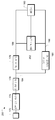
도 1은 일 실시예에 따른 시간 영역 채널과 주파수 영역 채널을 가지는 테스트 및 계측 기기의 블록도이다. 본 실시예에서, 기기(10)는 제1 입력 신호(18)를 수신하도록 구성된 시간 영역 채널(12), 및 제2 입력 신호(20)를 수신하도록 구성된 주파수 영역 채널(14)을 포함한다. 수집 시스템(acquisition system)(16)은 시간 영역 채널(12) 및 주파수 영역 채널(14)에 연결되고, 시간 영역 채널(12) 및 주파수 영역 채널(14)로부터 데이터를 수집하도록 구성된다.1 is a block diagram of a test and measurement instrument having a time domain channel and a frequency domain channel in accordance with an embodiment. In this embodiment, the
시간 영역 채널(12)은 시간 영역에서의 분석을 위해 제1 입력 신호(18)를 샘플링하도록 구성될 수 있다. 예를 들면, 시간 영역 채널(12)은 복수 비트(multi-bit)의 아날로그/디지털 변환기와 같은 디지타이저, 이산 레벨(discrete level)을 감지하는 비교기 등을 포함할 수 있다. 시간 영역 채널(12)은 증폭기, 입력 보호, 또는 다른 컨디셔닝 회로(conditioning circuitry)와 같은, 다른 회로를 포함할 수 있다. 시간 영역 채널(12)은 메모리, 데시메이터 등과 같은, 다른 디지털 처리 회로를 포함할 수 있다. 따라서, 출력 신호((26)는 시간 영역에서의 입력 신호(18)의 디지털화된 버전(digitized version)일 수 있다.The
일 실시예에서, 시간 영역 채널(12)은 시간 영역에서의 분석을 위한 신호의 수집에 최적화된 회로를 포함할 수 있다. 예를 들면, 시간 영역 분석에 적합한 신호는 제어 신호, 데이터 신호 등일 수 있다. 이러한 신호는 1 GHz, 26.5 GHz 등과 같은, DC에서 최대 주파수까지의 주파수 성분(frequency component)을 가질 수 있다. 따라서, 시간 영역 채널(12)은 증폭기, 감쇠기(attenuator), 및 DC에서 최대 주파수까지의 전 대역을 포함(cover)하는 다른 회로를 포함할 수 있다.In one embodiment, the
주파수 영역 채널(14)은 시간 영역 채널(12)과는 다르게 제2 입력 신호(20)를 처리하도록 구성될 수 있다. 특히, 주파수 영역 채널(14)은 주파수 영역에서의 분석을 위해 제2 입력 신호(20)를 처리하도록 구성될 수 있다. 예를 들면, 이하에 더욱 자세하게 설명하는 바와 같이, 제2 입력 신호(20)는 다른 주파수 범위로 주파수 편이될 수 있다. 특히, 제2 입력 신호(20)는 더 낮은 주파수 범위로 하향 변환될 수 있다. 즉, 제2 입력 신호(20)는 주파수 편이되었다. 일 실시예에서, 이 주파수 편이된 신호가 출력 신호(28)일 수 있다.The
이 주파수 편이는 시간 영역 채널(12)과 주파수 영역 채널(14)에 의한 입력 신호의 처리에 있어 차이점의 일례이다. 또, 일 실시예에서 주파수 영역 채널(14)은 주파수 영역의 표현 및 분석을 필요로 하는 신호에 대해 최적화될 수 있는 감쇠기, 필터, 증폭기 등을 포함할 수 있다. 예를 들면, 주파수 영역 채널(14)의 증폭기는 시간 영역 채널(12)의 증폭기보다 낮은 잡음 지수(noise figure) 및 낮은 최대 입력 레벨을 가지도록 구성될 수 있다. 다른 예에서, 증폭기는 다른 주파수 범위를 가질 수 있다. 즉, 시간 영역 채널(12)의 증폭기는 DC 내지 26.5 GHz의 주파수 범위를 가질 수 있다. 증폭기는 주파수 범위 전체에 걸쳐 증폭하는 신호에 대해 최적화될 수 있다. 그러나, 주파수 영역에서 고주파 신호를 분석할 때, 특히, 주파수 영역에서 하향 변환되었던 신호를 분석할 때, DC에서 최대 주파수까지의 전체 주파수 범위에 걸쳐 동작하지 않는 구성요소(component)들이 사용될 수 있다. 예를 들면, 관심대상의 신호(signal of interest)가 15 GHz에 중심이 있는 주파수 범위를 가지는 경우, 10 GHz에서 20 GHz까지의 주파수 범위를 가지는 증폭기가 사용될 수 있다. 이러한 증폭기는 DC에서 26.5 GHz까지의 더 넓은 주파수 범위에 걸쳐있는 증폭기보다 그 주파수 범위에 걸쳐 더 우수한 성능을 가질 수 있다.This frequency shift is an example of the difference in the processing of the input signal by the
마찬가지로, 주파수 영역 채널(14)은 시간 영역 채널(12)에 사용될지 모르는 상이한 대역폭, 입력 범위, 잡음 지수 등을 가지는 다른 성분을 포함할 수 있다. 즉, 주파수 영역 채널(14)에서의 증폭기, 믹서, 로컬 오실레이터(local oscillator), 감쇠기, 필터, 스위치 등은 주파수 영역 채널(14)의 전체 대역폭을 저하 및/또는 제거할 특성을 갖도록 선택될 수 있다.Likewise, the
따라서, 주파수 영역 채널(14)로부터의 전술한 주파수 편이, 전술한 주파수 영역 채널(14)과 상이한 구성요소의 작용 등으로 인해, 출력 신호(28)는 시간 영역 채널(12)에서 처리되는 경우보다 주파수 영역 분석을 위해 더욱 적절하게 처리된 신호일 수 있다. 또, 이하에 더욱 상세하게 설명하는 바와 같이, 입력 신호(20)는 입력 신호(20)는 관심대상인 주파수 범위, 분해능 대역폭(resolution bandwidth), 등에 적합할 수 있을 뿐 아니라, 시간 영역 채널(12)의 수집 파라미터와 상이할 수 있는 수집 파라미터와 관련된 주파수 영역에 따라 처리되었다. 즉, 주파수 영역 채널(14)은 시간 영역 채널(12)과는 상이한 구성요소를 가질 수 있을 뿐 아니라, 주파수 영역 채널(14)과 시간 영역 채널(12)은, 예를 들면, 상이한 샘플 레이트, 레코드 길이 등을 가짐으로써, 상이하게 동작될 수 있다. 따라서, 주파수 영역 채널(14)과 시간 영역 채널(12) 각각은 주파수 영역과 시간 영역 각각에서 수집된 신호의 대응하는 분석을 위해 최적화될 수 있다.Thus, due to the above-described frequency shift from the
수집 시스템(16)은 다양한 회로를 포함할 수 있다. 예를 들면, 수집 시스템은 디지타이저, 데시메이터, 필터, 메모리 등을 포함할 수 있다. 수집 시스템(16)은 시간 영역 채널(12)과 주파수 영역 채널(14)에 연결되고 시간 영역 채널과 주파수 영역 채널로부터 데이터를 수집하도록 구성될 수 있다. 예를 들면, 시간 영역 채널(12)은 수집 시스템의 디지타이저를 위한 적절한 범위 내에 들도록 출력 신호(26)를 필터링, 스케일링(scaling), 또는 컨디셔닝하도록 구성될 수 있다. 마찬가지로, 주파수 영역 채널(14)은 또한, 비록 전술한 바와 같은 시간 영역 채널(12)과 다르다 할지라도, 수집 시스템(16)의 디지타이저를 위해 신호를 컨디셔닝하도록 구성될 수 있다.The
도 2는 도 1의 테스트 및 계측 기기에 있어 주파수 영역 채널의 일례의 블록도이다. 이 예에서, 주파수 영역 채널(14)은 감쇠기(30), 필터(31), 로컬 오실레이터(33), 및 IF 필터(34)를 포함한다. 입력 신호(20)는 감쇠기(30)에 의해 수신된다. 감쇠기(30)는 고정((fixed) 감쇠기, 가변((variable) 감쇠기, 스위치형((switched) 감쇠기 등일 수 있다. 감쇠된 신호는 필터(31)에 의해 필터링된다. 일 실시예에서, 필터(31)는 적절한 입력 주파수 범위에 대해 원하는 바에 따라 선택될 수 있다. 예를 들면, 필터(31)는 관심대상의 특정 주파수 범위, 오실레이터(23) 주파수 등에 의존하는 저역 통과 필터, 대역 통과 필터, 고역 통과 필터 등일 수 있다.Figure 2 is a block diagram of an example of a frequency domain channel in the test and measurement instrument of Figure 1; In this example, the
필터링된 신호는 믹서(mixer)(32) 및 로컬 오실레이터(33)를 사용하여 IF 범위로 하향 변환될 수 있다. IF 필터(34)는, IF 신호가 출력 신호(24)로 이용 가능하기 이전에, IF 신호를 필터링할 수 있다. 본 실시예에서, 출력 신호(24)는, 수집 시스템(16)에 의해 수집에 이용 가능한, 도 1의 주파수 영역 채널(14) 출력 신호(28)일 수 있다. The filtered signal may be downconverted to IF
일 실시예에서, 출력 신호(24)는 IF 주파수 범위로 하향 변환 후의 입력 신호(20)를 나타낸다. 이 IF 신호는 도 1에 나타낸 바와 같이 수집 시스템(16)에서 더 처리되거나 수집될 수 있다. 예를 들면, 이하에 더욱 상세하게 설명하는 바와 같이, IF 신호는 푸리에 변환 등을 사용하여 변환된, 동위상(in-phase)(I) 및 직교 위상(quadrature phase)(Q) 신호로 변환될 수 있다.In one embodiment, the
다른 실시예에서, 주파수 영역 채널(14)은 디지타이저(35), 및 디지털 필터(36)를 포함할 수 있다. 디지타이저(35)는 출력 IF 신호(24)를 디지털화하도록 구성될 수 있다. 디지털 필터(36)는 디지털화된 IF 신호에 대해 인공물(artifact)을 감소시키고, 윈도잉 함수(windowing function)을 제공하는 등을 위해 적용될 수 있다. 따라서, 디지털화된 IF 신호(25)는, 수집 시스템(16)에 의해 수집될, 도 1의 주파수 영역 채널(14) 출력 신호(28)로서 이용 가능할 수 있다.In another embodiment, the
또 다른 실시예에서, 주파수 영역 채널(14)은 메모리(37), 및 고속 푸리에 변환(fast Fourier transform, FFT), 이산 푸리에 변환(discrete Fourier transform, DFT), chirp-Z 변환 등의 푸리에 변환(38)을 디지털화된 IF 신호(25)에 대해 수행하도록 구성된 프로세서를 포함할 수 있다. 이때, 디지털화된 IF 신호(25)는 변환되어, 그 수학적 표현을 시간의 함수에서, 변환된 신호(27)로 표현된, 주파수의 함수로 변경할 수 있다. 푸리에 변환(38)이 일례로 주어졌지만, 원하는 바에 따라 라플라스 변환(Laplace transform), 힐버트(Hilbert transform) 등의 다른 변환을 대체할 수 있다. 여하튼, 변환된 IF 신호(27)는, 수집 시스템(16)에 의해 수집될, 도 1의 주파수 영역 채널(14) 출력 신호(28)로 사용 가능할 수 있다.In another embodiment, the
따라서, 주파수 영역 채널(14) 출력 신호(28)는 주파수 영역에서 입력 신호(20)의 분석을 허용하기에 적합한 다양한 형태를 취할 수 있다. 다양한 구성요소, 처리 등은 원하는 바에 따라 주파수 영역 채널(14)과 시간 영역 채널(12) 간에 나뉠 수 있다. 그러나, 형태와 무관하게, 출력 신호(28)는 관심대상의 주파수 범위에 대해 선택 및/또는 튜닝(tunning)될 수 있는 구성요소에 의해 처리될 수 있다. 주파수 영역 채널(14) 출력 신호(28)의 형태와 관계없이, 시간 영역 채널(12) 및 주파수 영역 채널(14)로부터의 데이터를 포함하는 수집된 데이터(22)는 각각의 영역 등에서 추가적인 처리, 표시, 분석에 이용할 수 있다.Thus, the
일 실시예에서, 수집 시스템(16)은 출력 신호(26) 및 출력 신호(28)의 실질적으로 시간 정렬된 버전을 수집하도록 구성될 수 있다. 예를 들면, 출력 신호(26, 28)는 수집 시스템(16)의 수집 메모리에 저장될 수 있다. 이하에 더욱 상세하게 설명하는 바와 같이, 출력 신호(26, 28)의 수집은 동일한 트리거에 따라 수행될 수 있다. 따라서, 출력 신호(26)가 시간 영역 분석에 최적화된 시간 영역 채널(12)로 수집될 수 있고 출력 신호(28)가 주파수 영역 분석에 최적화된 주파수 영역 채널(14)로 수집될 수 있을 때, 실질적으로 시간 정렬된 시간 및 주파수 영역 분석은 하나의 분석 영역에 대한 최적화를 다른 영역을 희생시키지 않고서 수행될 수 있다.In one embodiment, the
주파수 영역 채널(14)의 구성요소의 선택을 설명하였지만, 증폭기, 스위치, 데시메이터 등의 다른 구성요소가 존재할 수 있고/있거나 설명한 구성요소를 대체할 수 있다.Although the selection of components of the
도 1을 참조하면, 일 실시예에서, 시간 영역 채널(12), 주파수 영역 채널(14), 및 수집 시스템(16)은 실질적으로 하우징(24) 내에 캡슐화될 수 있다. 예를 들면, 기기(10)는 케이스를 포함할 수 있다. 시간 영역 채널(12)은 전면 패널(front panel) 상에, BNC 커넥터, 다중채널 커넥터 등의, 입력 커넥터를 포함할 수 있다. 주파수 영역 채널(14)은 SMA, N, 2.92 mm, 또는 다른 고성능 커넥터와 같은, 고주파에 적합한 커넥터를 가질 수 있다. 즉, 주파수 영역 채널(14)은 더 높은 주파수 성능에 최적화된 커넥터를 포함할 수 있다.Referring to Figure 1, in one embodiment, the
하우징(24)은 공통의 디스플레이, 키(key), 놉(knob), 다이얼(dial), 또는 다른 사용자 인터페이스를 포함할 수 있다. 사용자 인터페이스의 공통의 측면들은 시간 영역 및 주파수 영역 신호의 다른 측면들을 제어할 수 있지만, 상이한 인터페이스들이 상이한 기능(function)을 액세스하기 위해 제공될 수 있다. 예를 들면, 하나의 버튼은 공통의 놉으로 하여금 시간 베이스(time base)를 제어하게 할 수 있다. 다른 버튼은 공통의 높이 중심 주파수를 제어하게 할 수 있다. The
일 실시예에서, 시간 영역 채널(12) 및 주파수 영역 채널(14)은 상이한 동작 주파수 범위를 가질 수 있다. 시간 영역 채널(12)은 제1 동작 주파수 범위를 가질 수 있다. 예를 들면, 시간 영역 채널(12)은 DC 결합될 수 있다. 즉, 시간 영역 채널(12)은 DC 신호 및/또는 DC에 이르기까지의 주파수 성분을 가지는 기저대역 신호(baseband signal)를 수집하는 데 사용될 수 있다. 시간 영역 채널(12)은 비교적 낮은 주파수 상한(upper frequency limit)을 가질 수 있다. 예를 들면, 시간 영역 채널(12)은 1 GHz 대역폭을 가질 수 있다. 따라서, 시간 영역 채널(12)은 DC 에서 1 GHz까지의 입력 주파수 범위를 가지도록 구성될 수 있다.In one embodiment, the
그러나, 주파수 영역 채널(14)은 다른 입력 주파수 범위를 가지도록 구성될 수 있다. 예를 들면, 도 2의 예에 나타낸 바와 같이, 주파수 영역 채널(14)은 입력 신호(20)를 더 낮은 IF 주파수 범위로 하향 변환하도록 구성될 수 있다. 따라서, 주파수 영역 채널(14)의 동작 입력 주파수 범위는 시간 영역 채널(12)과 다르도록 구성될 수 있다. 예를 들면, 주파수 영역 채널(14)의 입력 주파수 범위는 26.5 GHz까지 일 수 있다. 즉, 각종 필터(31, 34, 36) 등은 동작 입력 대역폭에 영향을 미칠 수 있다.However, the
또, 주파수 영역 채널(14)을 위해 선택되는 구성요소는 전체 입력 주파수 범위보다는, 연관된 주파수 범위를 최적화하기 위해 선택될 수 있다. 예를 들면, 구성요소는 특정 주파수 범위에 대한 최적의 감도, 동적 범위, 노이즈 레벨 등을 위해 선택될 수 있다. 이와는 대조적으로, 일 실시예에서는, 시간 영역 채널(12)은 그 전체 주파수 범위에 대해 최적화될 수 있다. 즉, 시간 영역 채널(12)은 그 전체 대역폭 내의 어디서든 신호를 기대하도록 구성될 수 있다. 그러나, 주파수 영역 채널(14)은 관심대상의 특정 주파수 범위를 선택하도록 구성될 수 있다. 또, 주파수 영역 채널(14)은 시간 영역 채널(12)의 대역폭 밖의 신호를 수집하도록 구성될 수 있다. 따라서, 주파수 영역 채널(14)은 그 주파수 범위에 대해 최적화될 수 있다.Also, the components selected for the
도 3은 일 실시예에 따른 단일 입력에 연결된 시간 영역 채널과 주파수 영역 채널을 가지는 테스트 및 계측 기기의 블록도이다. 본 실시예에서, 시간 영역 채널(12)과 주파수 영역 채널(14)은 각각 동일한 입력 신호(42)를 수신하도록 구성될 수 있다. 예를 들면, 스플리터(splitter), 스위치, 선택기, 또는 다른 신호 라우팅 디바이스(44)는 입력 신호(42)의 경로를 설정(route)하는 데 사용될 수 있다. 따라서, 일 구성예에서는, 시간 영역 채널(12)만이 입력 신호(42)를 수신한다. 다른 구성예에서는, 주파수 영역 채널(14)만이 입력 신호(42)를 수신한다. 또 다른 구성예에서는, 시간 영역 채널(12)과 주파수 영역 채널(14) 모두 입력 신호(42)를 수신할 수 있다. 3 is a block diagram of a test and measurement instrument having a time domain channel and a frequency domain channel coupled to a single input in accordance with one embodiment. In this embodiment, the
일 실시예에서, 시간 영역 채널(12)과 주파수 영역 채널(14) 각각은 각자의 디지타이저를 가질 수 있다. 따라서, 출력 신호(26, 28)는 시간 영역 및 주파수 영역 각각에서 분석을 위한 채널 최적화 시에 디지털화되었던 디지털 신호일 수 있다. 다른 실시예에서는, 전술한 바와 같이, 디지타이저는 수집 시스템(16)의 일부일 수 있다. 또, 출력 신호(26, 28)는 각각의 영역에서 수집 및 분석을 위해 최적화되도록 처리되었던 아날로그 신호일 수 있다.In one embodiment, each of the
도 4는 도 3의 테스트 및 계측 기기의 일례의 블록도이다. 본 실시예에서, 기기는 입력 신호(42)를 수신하도록 구성된 공통의 입력(44), 다운컨버터(57), 선택기(53) 및 디지타이저(55)를 포함한다. 다운컨버터(57)는 믹서(51)와 로컬 오실레이터(52)를 포함한다. 필터, 증폭기, 감쇠기 등의 다른 구성요소들은 명료성을 위해 나타내지 않는다. 다운컨버터(57)는 입력 신호(42)의 하향 변환된(downconverted) 버전(58)을 출력할 수 있다. 4 is a block diagram of an example of the test and measurement instrument of Fig. In this embodiment, the device includes a
입력 신호(42) 및 하향 변환된 신호(58) 모두는 선택기(53)에 사용 가능하다. 따라서, 단일 입력(44)에 대해, 다운컨버터(57) 및/또는 다른 연관된 증폭기, 필터 등과 같은, 주파수 영역에서의 분석을 위해 최적화될 수 있는 회로가 단일 채널에 추가될 수 있다. 그러나, 디지타이저(55)와 같은, 공통의 회로는 시간 영역과 주파수 영역에서 사용될, 직접 디지털화하는 입력 신호(42)는 물론 하향 변환된 신호(58) 모두에 대해 사용될 수 있다.Both the
예를 들면, 디지타이저(55)는 1 GS/s 샘플 레이트로 디지털화할 수 있다. 따라서, 시간 영역 경로(43)는, 500 MHz와 같은, 대응하는 최대 입력 주파수를 가질 수 있다. 이와는 대조적으로, 주파수 영역 경로(45)는 실질적으로 더 높은 최대 주파수 범위를 허용하는 구성요소를 포함할 수 있다. 예를 들면, 다운컨버터(57)는 26.5 GHz까지의 주파수를 가지는 신호를 하향 변환하도록 구성될 수 있다. 그러나, 하향 변환된 신호(58)의 IF 대역폭은 500 MHz일 수 있다. 따라서, 동일한 디지타이저(55) 및 공통의 회로를 기저대역 디지털 신호와 하향 변환된 신호 모두를 디지털화하는 데도 사용할 수 있다.For example, the
이하에 더욱 상세하게 설명하는 바와 같이, 디지타이저(55)는 주파수 영역 분석을 수행할 때, 시간 영역 분석을 수행할 때와는 다른 샘플 레이트로 동작하도록 구성될 수 있다. 예를 들면, 선택 신호(54)에 따라, 디지타이저(55)는 들어오는 신호에 적합한 샘플 레이트를 선택하도록 구성될 수 있다. 즉, 일 실시예에서, 시간 영역 분석을 위한 신호의 수집에는 높은 샘플 레이트를 사용할 수 있지만; 주파수 영역 분석을 위한 신호의 수집에는 하향 변환된 신호(58)에 적합한 낮은 샘플 레이트를 사용할 수 있다.As will be described in greater detail below, the
따라서, 동일한 입력이 시간 영역 분석에 최적화된 신호(26) 및 주파수 영역 분석에 최적화된 신호(28)를 모두 제공하도록 구성할 수 있다. 도 3에 나타낸 바와 같이, 동일한 입력 신호가 시간 영역과 주파수 영역에서 실질적으로 동시에 수집되고 분석될 수 있다. 그러나, 도 4의 실시예에 나타낸 바와 같이, 수집된 신호의 신호 경로는 시간 영역 분석에 최적화된 것과 주파수 영역 분석에 최적화된 다른 것 중에서 선택될 수 있다.Thus, the same input can be configured to provide both a
도 5는 일 실시예에 따른 다중 채널에 대해 상이한 수집 파라미터를 가지는 테스트 및 계측 기기의 블록도이다. 본 실시예에서, 기기(60)는 시간 영역 채널(63)과 주파수 영역 채널(67)을 포함하고, 이 각각은 전술한 도 1과 마찬가지로 수집 시스템(70)에 연결된다. 제어기(69)는 시간 영역 채널(63)과 주파수 영역 채널(67)에 연결된다. 이 제어기(69)는 임의의 여러 회로일 수 있다. 예를 들면, 제어기(69)는 아날로그 및 디지털 회로를 포함할 수 있다. 제어기(69)로는 범용 프로세서(general purpose processor), 디지털 신호 처리기(digital signal processor), 주문형 집적회로(application specific integrated circuit), 프로그래머블 게이트 어레이(programmable gate array) 등을 포함할 수 있다. 제어기(69)는 또한 시간 영역 채널(63), 주파수 영역 채널(67), 및 수집 시스템(70)과의 인터페이싱을 위한 적절한 회로를 포함할 수 있다.5 is a block diagram of a test and measurement instrument having different acquisition parameters for multiple channels in accordance with one embodiment. In this embodiment, the
제어기(69)는 시간 영역 채널(63)과 주파수 영역 채널(67)의 수집 파라미터를 제어하도록 구성될 수 있다. 특히, 제어기(69)는 수집 파라미터들이 상이할 수 있게 수집 파라미터를 제어하도록 구성될 수 있다. 이 예에서, 제어기(69)는 각각의 디지타이저(52, 66)의 샘플 레이트(64, 68)를 제어하도록 구성될 수 있다. 샘플 레이트(64, 68)는, 샘플 레이트(64)와 샘플 레이트(68)가 상이할 수 있도록 구성 가능하다. 따라서, 디지털화된 시간 영역 데이터(71)와 디지털화된 주파수 영역 데이터(73)의 길이는 상이할 수 있다.The
샘플 클록의 독립성(independence)은 시간 영역 및 주파수 영역 파라미터의 독립적인 제어를 가능하게 한다. 예를 들면, 시간 영역 신호를 수집하기 위해, 샘플 레이트를 시간 영역 신호에서의 관심대상의 최고 주파수 성분을 두 배 초과하도록 선택할 수 있다. 시간 영역 신호가 1 GHz의 주파수 성분을 가지는 경우, 2 GS/s 이상의 샘플 레이트를 사용할 수 있다. 주파수 영역 채널이 동일한 샘플 레이트에 대해 잠금상태(locked)인 경우, DFT를 사용할 때, 수파수 간격 크기(frequency step size) 또는 주파수 영역 데이터(73)의 연관된 분해등 대역폭은 샘플의 수, 또는 기간(time span)을 직접 만든다. 그 결과, 분해능 대역폭은 이용 가능한 수집 메모리 크기에 의해 제한된다. 다르게는, 시간 영역 채널(63)의 샘플 레이트는 주파수 영역 채널(67)에 대해 좁은 분해능 대역폭을 실현하기 위해 제한될 것이다.Independence of the sample clock enables independent control of time domain and frequency domain parameters. For example, to collect a time domain signal, the sample rate may be selected to exceed the highest frequency component of interest in the time domain signal by more than two times. If the time domain signal has a frequency component of 1 GHz, a sample rate of 2 GS / s or higher can be used. When the frequency domain channel is locked for the same sample rate, when using the DFT, the frequency step size or the associated disassembly bandwidth of the
이와는 대조적으로, 샘플 레이트가 상이할 수 있는 경우, 주파수 영역 데이터(73)의 원하는 측면에 적합한 샘플 레이트를 선택할 수 있다. 예를 들면, 여기에서 설명한 바와 같이 입력 신호(20)가 하향 변환되는 경우, 원하는 주파수 범위(frequency span)에 대응하는 더 낮은 샘플 레이트를 사용할 수 있다. 즉, 캐리어는 1 GHz이었고 변조는 20 MHz를 사용하였던 경우, 하향 변환된 신호는 20 MHz에 더해 필터링, 샘플링 등을 위해 추가적인 마진(margin)을 사용할 수 있었다. 이러한 샘플 레이트를 50 MS/s라고 가정하면, 1/40의 수집 메모리가 동일한 기간, 따라서 동일한 주파수 간격 크기에 대해 필요할 것이다. In contrast, if the sample rate may be different, a sample rate suitable for the desired side of the
상기한 시나리오는 상이한 샘플 레이트를 사용할 수 있다는 것을 나타내는 예일 뿐이다. 특정 애플리케이션과 관계없이, 상이한 샘플 레이트는 주어진 채널, 입력 신호, 및 관심대상의 영역에 대해 특별히 선택이 이루어질 수 있도록 해준다.The above scenario is only an example that indicates that different sample rates can be used. Regardless of the particular application, different sample rates allow a particular choice to be made for a given channel, input signal, and region of interest.
시간 영역 채널(63)과 주파수 영역 채널(67)에 대한 전술한 샘플 레이트는 상이할 수 있지만, 반드시 독립적인 것은 아니다. 예를 들면, 상이한 샘플 레이트는 공통의, 더 낮은 주파수 클록에 대해 위상 잠금상태(phase locked)일 수 있다. 그러나, 여기서 독립성은 독립적으로 제어 가능한 것을 의미할 수 있다. 또, 별개의 샘플 레이트(64, 68)를 설명하였지만, 연관된 오실레이터, 클록 등은 실질적으로 기기(60)의 공통의 회로와 동기화될 수 있다.The above-described sample rates for the
또, 샘플 레이트는 시간 영역 채널(63)과 주파수 영역 채널(67) 간에 상이할 수 있는 수집 파라미터의 일례로서 사용되었지만, 다른 수집 파라미터들이 제어기(69)에 의해 상이하도록 제어될 수 있다. 예를 들면, 제어기(69)는 시간 영역 채널(63)과 주파수 영역 채널(67)에 연관된 수집 기간, 레코드 길이 등이 상이하도록 수집 시스템(70)을 제어하도록 구성될 수 있다. 다른 예에서, 제어기(69)는 필터 대역폭, 필터 중심 주파수, 감쇠기 설정 등, 각 채널에서의 구성요소를 조정하도록 구성될 수 있다. 그 결과, 시간 영역 채널(63)과 주파수 영역 채널(67)에 대한 수집 파라미터들은 각각 연관된 입력 신호의 수집을 위해 채널을 최적화하도록 제어될 수 있어, 연관된 입력 신호가 상이한 영역들에서의 분석 위해 최적화된다. Also, although the sample rate is used as an example of a collection parameter that may be different between the
도 6은 일 실시예에 따른 시간 영역 채널 및/또는 주파수 영역 채널로부터의 수집을 트리거할 수 있는 트리거 시스템을 가지는 테스트 및 계측 기기의 블록도이다. 본 실시예에서, 기기(90)는 수집 시스템(92)을 포함한다. 수집 시스템(92)은 트리거링 시스템(94)을 포함할 수 있다. 이 트리거링 시스템은 시간 영역 채널(12)과 주파수 영역 채널(14)에 연결될 수 있다. 따라서, 수집 시스템(92)의 수집은 시간 영역 신호, 주파수 영역 신호, 이 신호들의 조합 등에 따라 트리거될 수 있다.6 is a block diagram of a test and measurement instrument having a trigger system capable of triggering acquisition from a time domain channel and / or a frequency domain channel in accordance with one embodiment. In this embodiment, the
주파수 및 시간 영역 모두에서의 수집을 트리거하기 위해 동일한 이벤트 또는 이벤트의 조합이 사용될 수 있을 때, 수집된 신호는 비교적 고정도(higher degree)로 시간 정렬될 수 있다. 예를 들면, 수집된 데이터는 오실로스코프의 두 입력 채널 같이 시간 정렬될 수 있다, 즉, 실질적으로 각 샘플 단위로 정렬될 수 있다. 따라서, 한 영역에서의 이벤트를 검사할 때, 대응하는, 실질적으로 다른 영역에서 실질적으로 동시에 발생하는 신호를 분석할 수 있다. 여기에 사용된 바와 같이, 실질적으로 동시에 발생하는 및/또는 시간 정렬되는 것은 시간 정렬된 채널의 가장 낮은 샘플 레이트에 의해 제한되는 시간 정밀도를 포함할 수 있다.When the same event or combination of events can be used to trigger the acquisition in both the frequency and time domains, the collected signal can be temporally aligned with a relatively higher degree. For example, the collected data may be time aligned, such as two input channels of an oscilloscope, i.e., substantially aligned for each sample unit. Thus, when examining an event in one area, it is possible to analyze signals that occur substantially simultaneously in corresponding, substantially different areas. As used herein, substantially simultaneously occurring and / or time aligned may include time precision limited by the lowest sample rate of the time aligned channel.
또, 공통의 트리거링은 교차 영역(cross-domain) 트리거링을 초래할 수 있다. 예를 들면, 수집 시스템(92)은 시간 영역 신호(18)에서의 이벤트를 식별하도록 구성될 수 있다. 응답으로, 주파수 영역 신호(20)의 수집이 트리거될 수 있다. 이 예에서는, 시간 영역 신호(18)를 수집할 필요는 없었다. 예를 들면, 송신기를 턴온하는 신호, 즉 시간 영역 제어 신호는 송신된 신호의 수집을 트리거하는 데 사용될 수 있다. 송신된 신호는 주파수 영역에서 분석될 수 있다.Also, common triggering can result in cross-domain triggering. For example, the
마찬가지로, 주파수 영역 이벤트는 시간 영역 수집을 트리거하는 데 사용될 수 있다. 예를 들면, 수신된 RF 신호는 주파수 범위가, 주파수 호핑 신호(frequency-hopping signal)와 연관된 범위 중 하나와 같은, 특정 주파수 범위로 변경될 때까지 모니터링될 수 있다. 수신기에서의 복조된 데이터의 수집은 관심대상의 주파수 범위 내의 RF 신호의 출현(appearance)에 따라 분석을 위해 수집될 수 있다.Likewise, a frequency domain event can be used to trigger a time domain acquisition. For example, the received RF signal can be monitored until the frequency range is changed to a specific frequency range, such as one of the ranges associated with the frequency-hopping signal. The collection of demodulated data at the receiver may be collected for analysis according to the appearance of the RF signal within the frequency range of interest.
한 영역에서의 이벤트가 다른 도메인에서의 분석을 위한 수집을 트리거하는 데 사용되는 것으로 설명하였지만, 동일한 이벤트가 임의의 또는 모든 영역에서의 분석을 위한 수집을 트리거하는 데 사용될 수 있다. 또, 상이한 영역들에서의 이벤트들은 함께 결합될 수 있다. 예를 들면, 주파수 영역 글리치(frequency domain glitch) 또는 다른 불요 신호(spurious signal)는 관심대상의 신호가 글리치를 가지는 주파수 범위 내에 있어야 한다는 것을 나타내는 제어 신호와 결합될 수 있다. 즉, 수신기와 연관된 신호는 주파수 영역 이상(anomaly)과 연관된 주파수 범위 내의 신호를 기대하고 있음을 나타내는 수신기의 제어 신호 모두에 따라 수집될 수 있다. 특정한 신호의 예, 신호의 특성, 이벤트의 조합 등을 설명하였지만, 임의의 신호로부터의 임의의 이벤트는 수집을 트리거하기 위해 원하는 바에 따라 사용 및/또는 조합될 수 있다.Although an event in one area has been described as being used to trigger an acquisition for analysis in another domain, the same event can be used to trigger a collection for analysis in any or all of the domains. Also, events in different regions can be combined together. For example, a frequency domain glitch or other spurious signal may be combined with a control signal indicating that the signal of interest should be within a frequency range with glitches. That is, the signal associated with the receiver may be collected in accordance with all of the receiver ' s control signals indicating that it is expecting a signal within the frequency range associated with the anomaly in the frequency domain. Although specific examples of signals, characteristics of signals, combinations of events, etc. have been described, any event from any signal may be used and / or combined as desired to trigger the acquisition.
도 7은 다른 실시예에 따른 시간 영역 채널 및 주파수 영역 채널을 가지는 테스트 및 계측 기기의 블록도이다. 본 실시예에서, 기기(110)는 시간 영역 채널(129)과 주파수 영역 채널(127)을 포함한다. 각 채널은 각자의 디지타이저(112, 114)를 포함한다. 주파수 영역 채널은 입력 신호(20)를 수신하도록 구성된 아날로그 다운컨버터(125)를 포함한다. 디지타이저(114)는 아날로그 다운컨버터(125)로부터의 신호를 하향 변환하도록 구성된다.7 is a block diagram of a test and measurement instrument having a time domain channel and a frequency domain channel according to another embodiment. In this embodiment, the
일 실시예에서, 디지타이저(112, 114)에서 디지털화된 신호는 메모리(116)에 저장될 수 있다. 이하에 설명하는 바와 같이, 그 다음의 처리는 메모리(116)에 저장된 디지털화된 신호에 대해 원하는 바에 따라 수행될 수 있다.In one embodiment, the digitized signals at the
디지털화된 신호가 메모리(116)에 저장되는지 여부와 관계없이, 추가적인 처리가 수행될 수 있다. 예를 들면, 디지털화된 신호(118)는 시간 영역 처리부(122)에 의해 추가로 처리될 수 있다. 예를 들면, 신호 컨디셔닝, 필터링, 데시메이션 등이 시간 영역 신호(118)에 적용될 수 있다. 그 결과인 처리된 시간 영역 신호(126)는 메모리(134)에 저장될 수 있다.Regardless of whether the digitized signal is stored in the
주파수 영역 채널(127)은 또한 디지털 다운컨버터(124)를 포함할 수 있다. 이 디지털 다운컨버터(124)는 디지털화 하향 변환된 신호(120)를 동위상(I) 및 직교 위상(Q) 표현으로 변환하도록 구성될 수 있다. 이것은 추가적인 하향 변환 처리를 통해 달성될 수 있다. 따라서, 하향 변환된 신호(128)는 입력 신호(20)의 동위상 및 직교 위상 표현 모두를 포함할 수 있다. 다른 예에서, I/Q 신호는 진폭, 위상, 주파수 등과 같은, 다른 신호로 변환될 수 있다. 또, I/Q 신호는 기초가 되는(underlying) 심볼, 비트 등을 포착하기 위해 보조될 수 있다. 다른 예에서는, FFT와 같은 변환이 적용될 수 있다. 이러한 처리는 어느 것이든 메모리(134)에 저장될 이들 신호 중 어느 것 또는 다른 신호를 생성하기 위해 수행될 수 있다.The
도 8은 도 7의 테스트 및 계측 기기의 디지털 다운컨버터의 일례의 블록도이다. 본 실시예에서, 디지털화된 신호(120)는 동위상 경로(148) 및 직교 위상 경로(150) 모두에 입력된다. 각 경로는 로컬 오실레이터(142)로부터의 신호를 수신하도록 구성되지만; 직교 위상 경로(150)는 동위상 경로(148)에 의해 수신된 신호와 위상이 90도 다른 신호를 수신하도록 구성된다.8 is a block diagram of an example of a digital downconverter of the test and measurement instrument of FIG. In this embodiment, the
각 경로(148, 150)는 입력 신호(120)를 로컬 오실레이터(142)로부터의 대응하는 신호와 혼합하도록 구성된다. 따라서, 동위상 신호(144)와 직교 위상 신호(146)가 생성된다. 추가적인 필터링 및/또는 데시메이션이 원하는 바에 따라 신호(144, 146)에 적용될 수 있다. 도 7과 관련하여 전술한 바와 같이, 이 신호들은 메모리(134)에 저장되고, 추가적인 처리 등이 될 수 있다. 특히, 신호(144, 146)는 디지털화된 신호(120)의 복소 표현(complex-number representation)일 수 있다. 예를 들면, 동위상 신호(144)는 디지털화된 신호(120)의 실수부를 나타낼 수 있고 직교 위상 신호(146)는 디지털화된 신호9120)의 허수부를 나타낼 수 있다. 이러한 복소 표현은 위상, 주파수, 인코딩된 신호 등의, 디지털화된 신호(1200의 여러 다른 표현을 계산하는 데 사용될 수 있다.Each
도 9는 다른 실시예에 따른 테스트 및 계측 기기의 블록도이다. 전술한 바와 같이, 수집이 시간 영역 분석과 주파수 영역 분석 각각에 최적화되도록 두 개의 신호가 수집될 수 있다. 일 실시예에서, 시간 영역 및 주파수 영역 분석에 대한 최적화와 더불어 디지털화 후에는, 동일한 입력 신호가 취득될 수 있다.9 is a block diagram of a test and measurement instrument according to another embodiment. As described above, two signals may be collected such that the collection is optimized for each of the time domain analysis and the frequency domain analysis. In one embodiment, after digitization, along with optimization for time domain and frequency domain analysis, the same input signal can be obtained.
일 실시예에서, 기기(170)는 입력 포트(172)를 포함할 수 있다. 이 입력 포트(172)는 입력 신호를 수신하도록 구성될 수 있다. 입력 신호는 신호 컨디셔닝부(174)에 의해 처리될 수 있다. 이 신호 컨디셔닝부(174)는 증폭기, 감쇠기, 리미터(limiter), 필터 등의 회로를 포함할 수 있다. 디지털화를 위한 입력 신호의 준비에사용될 수 있는 임의의 회로가 사용될 수 있다.In one embodiment, the
일단 컨디셔닝된, 입력 신호는 디지타이저(176)에 의해 디지털화될 수 있다. 이 디지타이저(176)는 전술한 바와 같은 임의의 각종 디지타이저일 수 있다. 디지타이저(176)는 입력 신호를 디지털화하여 디지털화된 입력 신호(184)를 생성하도록 구성된다. 일 실시예에서, 디지타이저(176)는 실질적으로 디지타이저의 최대 샘플 레이트인 샘플 레이트로 입력 신호를 샘플링하도록 구성될 수 있다. 따라서, 최고의 가능한 대역폭을 가지는 입력 신호를 샘플링할 수 있다. 그러나, 다른 실시예에서, 디지타이저는 원하는 바에 따라 더 낮은 샘플 레이트로 동작될 수 있다.Once conditioned, the input signal can be digitized by the
일례로서 디지타이저(176)의 최고 샘플 레이트를 사용함으로써, 입력 신호(184)는 비교적 높은 샘플 레이트를 가질 수 있다. 이러한 디지털화된 입력 신호(184)가 메모리에 저장되는 경우, 비교적 대량의 메모리가 필요하다. 그러나, 기기(170)는 데시메이터(178)를 포함할 수 있다. 이 데시메이터(178)는 디지타이저(176)에 연결되고 디지털화된 입력 신호(184)를 데시메이트하고, 데시메이트된 입력 신호(188)를 생성하도록 구성될 수 있다. 예를 들면, 디지타이저(176)는 1 GS/s 샘플 레이트로 샘플링하도록 구성될 수 있다. 데시메이터(178)는 디지털화된 입력 신호(184)를 10배로 데시메이트하도록 구성될 수 있다. 즉, 결과로 얻은 데시메이트된 신호(188)는 1 GS/s의 샘플 레이트를 가질 수 있다. 따라서, 주어진 기간에 동안에 더 작은 크기의 레코드가 메모리(182)에 저장될 수 있어, 필요한 메모리의 양을 감소시키고/시키거나 더 긴 수집을 가능하게 한다.By using the highest sample rate of the
이러한 데시메이션은 디지털화된 입력 신호(184)의 다음 시간 영역 분석에 적합할 수 있지만, 이 데시메이션은 주파수 영역 분석에 적합하지 않을 수 있다. 예를 들면, 비교적 더 작은 분해능 대역폭이 주파수 영역 분석에 바람직할 수 있다. 그 결과, 상대적으로 긴 기간이 더 작은 분해능 대역폭을 달성하기 위해 사용될 수 있다. 그러나, 디지털화된 입력 신호(184)의 샘플 레이트, 메모리(182) 내의 충분한 양의 저장 공간은 사용할 수 없다. 또, 데시메이터(178)에 의한 데시메이션은 주파수 영역에서 원하는 신호의 표현을 저하시킬 수 있다.This decimation may be suitable for the next time domain analysis of the digitized
따라서, 기기(170)은 디지털 다운컨버터(180)를 포함할 수 있다. 이 디지털 다운컨버터(180)는 디지타이저(176)에 연결되고 디지털화된 입력 신호(184)를 주파수 편이시켜 주파수 편이된 입력 신호(186)를 생성하도록 구성된다. 전술한 도 8은 디지털 다운컨버터(180)의 일례이다. 그러나, 다른 실시예에서, 디지털 다운컨버터(180)는 다수의 경로, 90도 위상 시프트 등을 포함하지 않아도 된다. 즉, 디지털 다운컨버터(180)는 도 8의 디지털 다운컨버터의 단일 경로와 마찬가지로, 디지털 믹싱, 필터링 등을 포함할 수 있다.Thus, the
여하튼, 디지털화된 입력 신호(184)의 관심대상의 주파수 범위는 IF 주파수 범위로 주파수 편이될 수 있다. 샘플 레이트, 레코드 길이 등은 주파수 편이된 입력 신호(186)의 저장을 위해 최적화되도록 선택될 수 있다. 예를 들면, 100 ms의 기간(time span)을 초래하는, 10 Hz 분해능 대역폭이 바람직할 수 있다. 디지털화된 입력 신호(184)의 10 GS/s 샘플 레이트에서는, 1 GS 레코드가 메모리(182)에 저장될 것이다. 그러나, 원하는 주파수 범위를 더 낮은 주파수로 주파수 편이시킴으로써, 더 낮은 샘플 레이트를 사용하여도 원하는 주파수 성분을 유지할 수 있다. 그리고 그에 따라 더 작은 레코드 길이가 동일한 분해능 대역폭에 사용될 수 있다.In any case, the frequency range of interest of the digitized
따라서, 메모리(182)는 데시메이트된 입력 신호(188) 및 주파수 편이된 입력 신호(186)를 저장하도록 구성될 수 있고, 각 신호는 시간 영역 및 주파수 영역 각각에서의 대응하는 분석에 적절하게 데시메이트된 것이다. 즉, 샘플 레이트, 레코드 길이 등은 시간 영역 분석과 주파수 영역 분석 모두에 원하는 바에 따라 선택될 수 있다. 특히, 샘플 레이트, 레코드 길이 등은 관심대상의 대응하는 분석 도메인에 대해 디지털화된 신호를 최적화하고 필요한 메모리의 양을 감소시키기 위해 원하는 바에 따라 선택될 수 있다.Thus, the
또, 일 실시예에서, 데시메이터(178)와 디지털 다운컨버터(180)는 실질적으로 동시에 동작하도록 구성될 수 있다. 그 결과, 동일한 입력 신호가 시간 영역과 주파수 영역에서 실질적으로 동시에 분석될 수 있다.Also, in one embodiment,
또한, 일 실시예에서, 샘플 레이트 및/또는 레코드 길이의 감축이 메모리(182)에 저장하기 전에 수행될 수 있다. 예를 들면, 디지털화된 입력 신호(184)는 추가적인 처리를 위해 메모리(182)에 저장되지 않을 수 있다. 데시메이터(178)와 디지털 다운컨버터(180)는 디지털화된 입력 신호(184)의 들어오는 디지털화된 데이터 스트림에 대해 동작하도록 구성될 수 있다. 따라서, 디지털화된 입력 신호(184)의 다음의 판독 및 처리를 수행할 필요가 없다. 다시 말해, 데시메이트된 입력 신호(188)와 주파수 편이된 입력 신호(186)가 메모리(182)에 저장됨으로써, 디지털화된 입력 신호(184)의 판독 및/또는 처리로 인한 지연이 발생하지 않아야 한다. 그 결과, 디지털화된 입력 신호(184)의 추가적인 처리를 위한 시간이 불필요할 수 있다.Also, in one embodiment, reductions in sample rate and / or record length may be performed prior to storage in
도 10은 일 실시예에 따른 트리거 시스템을 구비한 도 9의 테스트 및 계측 기기의 블록도이다. 전술한 바와 같이, 트리거 시스템은 시간 영역 채널과 주파수 영역 채널로부터의 이벤트에 대해 트리거하도록 구성될 수 있다. 일 실시예에서, 트리거 시스템(202)은 데시메이트된 입력 신호(188)와 주파수 편이된 입력 신호(186) 중 적어도 하나에 따라 수집을 트리거하도록 구성될 수 있다. 10 is a block diagram of the test and measurement instrument of FIG. 9 with a trigger system in accordance with one embodiment. As described above, the trigger system may be configured to trigger on events from time-domain channels and frequency-domain channels. In one embodiment, the trigger system 202 may be configured to trigger the acquisition in accordance with at least one of the decimated
일 실시예에서, 상기 수집은 디지털화된 입력 신호(184) 또는 임의의 파생 신호(derivative signal)의 수집일 수 있으나, 반드시 그런 것은 아니다. 즉, 트리거 시스템(202)은 데시메이트된 입력 신호(188)와 주파수 편이된 입력 신호(186)에 따라 다른 채널에 대한 데이터의 수집을 트리거하도록 구성될 수 있다.In one embodiment, the collection may be, but is not necessarily, a collection of digitized
도 11은 일 실시예에 따른 사용자 인터페이스를 구비한 도 9의 테스트 및 계측 기기의 블록도이다. 제어기(222)는 전술한 바와 같은 임의의 각종 회로일 수 있다. 특히, 제어기(222)는 데시메이터(178) 및 디지털 다운컨버터(180)에 연결될 수 있다. 제어기(222)는 데시메이터(178)의 파라미터 및 디지털 다운컨버터(180)의 파라미터를 사용자 인터페이스(224)에 따라 조정하도록 구성될 수 있다.FIG. 11 is a block diagram of the test and measurement instrument of FIG. 9 with a user interface according to one embodiment. The
일 실시예에서, 제어기(22)는 데시메이터(178) 및 디지털 다운컨버터(180)의 샘플 레이트, 레코드 길이, 중심 주파수 등, 각종 파라미터를 조정하도록 구성될 수 있다. 이러한 파라미터들은 전술한 바와 같이 데시메이터(178)와 디지털 다운컨버터(180) 간에 상이할 수 있다.In one embodiment, the
도 12는 일 실시예에 따른 도 11의 사용자 인터페이스의 일례의 블록도이다. 도 11 및 도 12를 참조하면, 일 실시예에서, 사용자 인터페이스(240)는 디스플레이(242)를 포함할 수 있다. 제어기(222)는 사용자 인터페이스(240)를 통해 데시메이트된 입력 신호(188)와 주파수 편이된 입력 신호(186)를 나타내도록 구성될 수 있다. 이 예에서, 시간 영역 트레이스(time domain trace)(248)는 데시메이트된 입력 신호(188)에 대응한다. 주파수 영역 트레이스(250)는 주파수 편이된 입력 신호(186)에 대응한다.12 is a block diagram of an example of the user interface of Fig. 11 according to one embodiment. Referring to Figures 11 and 12, in one embodiment, the
특히, 주파수 편이된 입력 신호(186)는 주파수 성분(252)의 분해 및 분석을 가능하게 하는 분해능 대역폭으로 나타낼 수 있다. 예를 들면, 전원 공급 장치의 노이즈 또는 다른 인공물들이 트레이스(248)로 나타나는 신호에 나타날 수 있다. 메모리(182)에 저장된 대응하는 레코드는 원한 특성의 분석을 가능하게 하면서도 메모리 사용을 감소시키도록 최적화될 수 있다.In particular, the frequency shifted
특히, 사용자 인터페이스(240)는 시간 영역 제어(244)와 주파수 영역 제어(246)를 포함할 수 있다. 시간 영역 제어(244)는 시간 분해능(time per division), 기간(time span), 샘플 레이트, 레코드 길이 등의 제어를 포함할 수 있다. 주파수 영역 제어(246)는 주파수 범위, 분해능 대역폭, 중심 주파수 등의 제어를 포함할 수 있다. 시간 영역 제어(244)와 주파수 영역 제어(246)는 원하는 바에 따라 사용자에게 제시될 수 있다. 예를 들면, 버튼, 다이얼, 메뉴 등이 시간 영역 제어(244) 및 주파수 영역 제어(246)를 사용자에게 제시하기 위해 사용될 수 있다. 또, 이러한 제어는 이더넷(Ethernet) 인터페이스, 범용 직렬 버스(universal serial bus, USB) 인터페이스, IEEE-488 인터페이스 등에 의해 사용자에게 제시될 수 있다.In particular, the
일 실시예에서, 제어기는 데시메이트된 입력 신호와 주파수 편이된 입력 신호를 사용자 인터페이스를 통해 실질적으로 동시에 나타내도록 구성될 수 있다. 따라서, 사용자는 원하는 바에 따라 단일 신호 입력의 복수의 측면을 다중 영역에서 분석할 수 있다.In one embodiment, the controller may be configured to substantially simultaneously represent the frequency-shifted input signal with the decimated input signal through the user interface. Thus, the user can analyze multiple aspects of a single signal input in multiple regions as desired.
이상에서는 데시메이션을 샘플 레이트를 감소시키는 것으로 데시메이터(178)와 관련하여 설명하였지만, 데시메이션은 다른 신호 처리를 포함할 수 있다. 예를 들면, 신호 성형(signal shaping), 필터링 등이 데시메이터(178)의 데시메이션의 일부일 수 있다.Although decimation has been described above with respect to the
이상에서는 주파수 영역 처리와 관련하여 DFT를 설명하였지만, 임의의 푸리에 변환 또는 다른 변환 함수를 원하는 바에 따라 사용할 수 있다.Although the DFT has been described above with respect to frequency domain processing, any Fourier transform or other transform functions may be used as desired.
이상에서는 여러 신호를 주파수가 하향 변환되는 것으로 설명하였지만, 그러한 신호는 원하는 바에 따라 적절한 IF 주파수 범위로 상향 변환(upconvert)될 수 있다. 예를 들면, IF 주파수 범위 아래의 주파수는 IF 주파수 범위로 상향 변환될 수 있다. 이러한 상향 변환 및 하향 변환은 집합적으로 주파수 편이라고 한다.Although various signals have been described above as frequency downconverted, such signals may be upconverted to the appropriate IF frequency range as desired. For example, frequencies below the IF frequency range may be up converted to the IF frequency range. These up-conversion and down-conversion are collectively referred to as frequency division.
이상에서는 특정한 실시예들을 설명하였지만, 본 발명의 원리는 이러한 실시예에 한정되는 것이 아님을 알 것이다. 이하의 특허청구범위에 기재된 본 발명의 원리를 벗어나지 않고서 변형 및 수정이 가해질 수 있다.Although specific embodiments have been described above, it will be appreciated that the principles of the invention are not limited to these embodiments. Variations and modifications may be made without departing from the principles of the invention as set forth in the following claims.
Claims (18)
상기 입력 신호를 디지털화하도록 구성된 디지타이저;
상기 디지타이저에 연결되고 상기 디지털화된 입력 신호를 데시메이트하여 데시메이트된 입력 신호를 생성하도록 구성된 데시메이터;
상기 디지타이저에 연결되고 상기 디지털화된 입력 신호를 주파수 편이시켜 주파수 편이된 입력 신호를 생성하도록 구성된 디지털 다운컨버터; 및
상기 데시메이트된 입력 신호 및 상기 주파수 편이된 입력 신호를 저장하도록 구성된 메모리
를 포함하는 테스트 및 계측 기기.An input port configured to receive an input signal;
A digitizer configured to digitize the input signal;
A decimator coupled to the digitizer and configured to decimate the digitized input signal to produce a decimated input signal;
A digital downconverter coupled to the digitizer and configured to frequency shift the digitized input signal to produce a frequency shifted input signal; And
A memory configured to store the decimated input signal and the frequency shifted input signal;
≪ / RTI >
상기 데시메이트된 입력 신호 및 상기 주파수 편이된 입력 신호는 상이한 샘플 레이트를 가지는, 테스트 및 계측 기기.The method according to claim 1,
Wherein the decimated input signal and the frequency shifted input signal have different sample rates.
상기 데시메이트된 입력 신호 및 상기 주파수 편이된 입력 신호는 상이한 레코드 길이를 가지는, 테스트 및 계측 기기.The method according to claim 1,
Wherein the decimated input signal and the frequency shifted input signal have different record lengths.
상기 디지타이저는 상기 입력 신호를 제1 샘플 레이트로 샘플링하도록 구성되고;
상기 데시메이터는 상기 제1 샘플 레이트보다 낮은 제2 샘플 레이트로 상기 데시메이트된 입력 신호를 생성하도록 구성되고;
상기 디지털 다운컨버터는 상기 제1 샘플 레이트보다 낮은 제3 샘플 레이트로 상기 주파수 편이된 입력 신호를 생성하도록 구성되는, 테스트 및 계측 기기.The method according to claim 1,
The digitizer being configured to sample the input signal at a first sample rate;
Wherein the decimator is configured to generate the decimated input signal at a second sample rate lower than the first sample rate;
Wherein the digital downconverter is configured to generate the frequency shifted input signal at a third sample rate lower than the first sample rate.
사용자 인터페이스; 및
상기 데시메이트된 입력 신호 및 상기 주파수 편이된 입력 신호를 상기 사용자 인터페이스를 통해 나타내도록 구성된 제어기
를 더 포함하는 테스트 및 계측 기기.The method according to claim 1,
User interface; And
A controller configured to display the decimated input signal and the frequency shifted input signal through the user interface,
Further comprising a test and measurement instrument.
상기 제어기는 상기 데시메이트된 입력 신호 및 상기 주파수 편이된 입력 신호를 상기 사용자 인터페이스를 통해 실질적으로 동시에 나타내도록 구성되는, 테스트 및 계측 기기.6. The method of claim 5,
Wherein the controller is configured to substantially simultaneously represent the decimated input signal and the frequency shifted input signal through the user interface.
상기 사용자 인터페이스는 시간 영역 제어 및 주파수 영역 제어를 포함하고;
상기 제어기는,
상기 시간 영역 제어에 따라 상기 데시메이터의 파라미터를 조정하도록 구성되고;
상기 주파수 영역 제어에 따라 상기 디지털 다운컨버터의 파라미터를 조정하도록 구성되는, 테스트 및 계측 기기.6. The method of claim 5,
Wherein the user interface comprises time domain control and frequency domain control;
The controller comprising:
And adjust the parameter of the decimator according to the time domain control;
And adjust the parameters of the digital downconverter according to the frequency domain control.
상기 제어기는,
상기 시간 영역 제어에 따라 상기 데시메이터의 샘플 레이트를 조정하도록 구성되고;
상기 주파수 영역 제어에 따라 상기 디지털 다운컨버터의 샘플 레이트를 조정하도록 구성되는, 테스트 및 계측 기기.8. The method of claim 7,
The controller comprising:
Adjust the sample rate of the decimator according to the time domain control;
And adjust the sample rate of the digital downconverter according to the frequency domain control.
상기 데시메이터 및 상기 디지털 다운컨버터에 연결되고, 상기 데시메이트된 입력 신호 및 상기 주파수 편이된 입력 신호 중 적어도 하나에 따라 수집을 트리거하도록 구성 가능한 트리거 시스템을 더 포함하는 테스트 및 계측 기기.The method according to claim 1,
And a trigger system coupled to the decimator and the digital downconverter and configured to trigger the acquisition in accordance with at least one of the decimated input signal and the frequency shifted input signal.
입력 신호를 디지털화는 단계;
상기 디지털화된 입력 신호를 데시메이트하여 데이메이트된 입력 신호를 생성하는 단계;
상기 디지털화된 입력 신호를 주파수 편이시켜 주파수 편이된 입력 신호를 생성하는 단계; 및
상기 데시메이트된 입력 신호 및 상기 주파수 편이된 입력 신호를 메모리에 저장하는 단계
를 포함하는 방법.A method of operating a test and metering device,
Digitizing the input signal;
Decimating the digitized input signal to produce a dematted input signal;
Generating a frequency-shifted input signal by frequency shifting the digitized input signal; And
Storing the decimated input signal and the frequency shifted input signal in a memory
≪ / RTI >
상기 데시메이트된 입력 신호 및 상기 주파수 편이된 입력 신호는 상이한 샘플 레이트를 가지는, 방법.11. The method of claim 10,
Wherein the decimated input signal and the frequency shifted input signal have different sample rates.
상기 데시메이트된 입력 신호 및 상기 주파수 편이된 입력 신호는 상이한 레코드 길이를 가지는, 방법.11. The method of claim 10,
Wherein the decimated input signal and the frequency shifted input signal have different record lengths.
상기 입력 신호를 디지털화하는 단계는 상기 입력 신호를 제1 샘플 레이트로 디지털화하는 단계를 포함하고;
상기 디지털화된 입력 신호를 데시메이트하는 단계는 상기 디지털화된 입력 신호를 상기 제1 샘플 레이트보다 낮은 제2 샘플 레이트로 데시메이트하는 단계를 포함하고;
상기 디지털화된 입력 신호를 주파수 편이시키는 단계는 상기 디지털화된 입력 신호를 상기 제1 샘플 레이트보다 낮은 제3 샘플 레이트로 주파수 편이시키는 단계를 포함하는, 방법.11. The method of claim 10,
Wherein digitizing the input signal comprises digitizing the input signal at a first sample rate;
Decimating the digitized input signal comprises decimating the digitized input signal to a second sample rate lower than the first sample rate;
Wherein frequency shifting the digitized input signal comprises frequency shifting the digitized input signal to a third sample rate lower than the first sample rate.
상기 데시메이트된 입력 신호 및 상기 주파수 편이된 입력 신호를 상기 사용자 인터페이스를 통해 나타내는 단계를 더 포함하는 방법.11. The method of claim 10,
Indicating the decimated input signal and the frequency shifted input signal through the user interface.
상기 데시메이트된 입력 신호 및 상기 주파수 편이된 입력 신호를 상기 사용자 인터페이스를 통해 실질적으로 동시에 나타내는 단계를 더 포함하는 방법.15. The method of claim 14,
And displaying the decimated input signal and the frequency shifted input signal substantially simultaneously through the user interface.
상기 사용자 인터페이스의 시간 영역 제어에 따라 상기 디지털화된 입력 신호의 데시메이션을 조정하는 단계; 및
상기 사용자 인터페이스의 상기 주파수 영역 제어에 따라 상기 디지털화된 입력 신호의 주파수 편이를 조정하는 단계를 더 포함하는 방법.15. The method of claim 14,
Adjusting decimation of the digitized input signal according to time domain control of the user interface; And
Further comprising adjusting a frequency shift of the digitized input signal in accordance with the frequency domain control of the user interface.
상기 사용자 인터페이스의 상기 시간 영역 제어에 따라 데시메이터의 샘플 레이트를 조정하는 단계; 및
상기 사용자 인터페이스의 상기 주파수 영역 제어에 따라 상기 주파수 편이의 샘플 레이트를 조정하는 단계를 더 포함하는 방법.17. The method of claim 16,
Adjusting a decimator sample rate according to the time domain control of the user interface; And
And adjusting the sample rate of the frequency shift in accordance with the frequency domain control of the user interface.
상기 데시메이트된 입력 신호와 상기 주파수 편이된 입력 신호 중 적어도 하나에 따라 수집을 트리거하는 단계를 더 포함하는 방법.11. The method of claim 10,
And triggering the acquisition in accordance with at least one of the decimated input signal and the frequency shifted input signal.
Applications Claiming Priority (2)
| Application Number | Priority Date | Filing Date | Title |
|---|---|---|---|
| US12/892,774 | 2010-09-28 | ||
| US12/892,774 US8521460B2 (en) | 2010-09-28 | 2010-09-28 | Multi-domain test and measurement instrument |
Related Parent Applications (1)
| Application Number | Title | Priority Date | Filing Date |
|---|---|---|---|
| KR1020170104833A Division KR20170097599A (en) | 2010-09-28 | 2017-08-18 | Multi-domain test and measurement instrument |
Publications (2)
| Publication Number | Publication Date |
|---|---|
| KR20180039607A true KR20180039607A (en) | 2018-04-18 |
| KR102011389B1 KR102011389B1 (en) | 2019-10-14 |
Family
ID=45044307
Family Applications (3)
| Application Number | Title | Priority Date | Filing Date |
|---|---|---|---|
| KR1020110098167A Active KR101771164B1 (en) | 2010-09-28 | 2011-09-28 | Multi-domain test and measurement instrument |
| KR1020170104833A Ceased KR20170097599A (en) | 2010-09-28 | 2017-08-18 | Multi-domain test and measurement instrument |
| KR1020180041563A Active KR102011389B1 (en) | 2010-09-28 | 2018-04-10 | Multi-domain test and measurement instrument |
Family Applications Before (2)
| Application Number | Title | Priority Date | Filing Date |
|---|---|---|---|
| KR1020110098167A Active KR101771164B1 (en) | 2010-09-28 | 2011-09-28 | Multi-domain test and measurement instrument |
| KR1020170104833A Ceased KR20170097599A (en) | 2010-09-28 | 2017-08-18 | Multi-domain test and measurement instrument |
Country Status (6)
| Country | Link |
|---|---|
| US (1) | US8521460B2 (en) |
| EP (2) | EP3460490B1 (en) |
| JP (1) | JP6203471B2 (en) |
| KR (3) | KR101771164B1 (en) |
| CN (1) | CN102435846B (en) |
| TW (1) | TWI534433B (en) |
Families Citing this family (19)
| Publication number | Priority date | Publication date | Assignee | Title |
|---|---|---|---|---|
| US9291646B2 (en) * | 2012-07-27 | 2016-03-22 | Tektronix, Inc. | Cross domain triggering in a test and measurement instrument |
| US10371732B2 (en) * | 2012-10-26 | 2019-08-06 | Keysight Technologies, Inc. | Method and system for performing real-time spectral analysis of non-stationary signal |
| CN103837739B (en) * | 2012-11-27 | 2016-12-21 | 江苏绿扬电子仪器集团有限公司 | Time domain and frequency domain synthesis test device |
| CN103019117B (en) * | 2012-12-06 | 2015-04-22 | 北京航天测控技术有限公司 | Digitalizer based on PXI e interface |
| US9952281B2 (en) | 2013-07-04 | 2018-04-24 | Nvidia Corporation | Clock jitter and power supply noise analysis |
| IL228776A0 (en) * | 2013-10-08 | 2014-03-31 | Rabinovich Roman | Analog -to-inforamation converter via spectrum-compression |
| CN104080205A (en) * | 2014-05-19 | 2014-10-01 | 苏州市职业大学 | Millimeter-wave wireless communication industrial Ethernet gateway |
| CN105699724B (en) * | 2016-03-25 | 2018-08-14 | 北华航天工业学院 | Long-range hybrid domain analog measurement instrument |
| US10641796B2 (en) * | 2017-08-14 | 2020-05-05 | Rohde & Schwarz Gmbh & Co. Kg | Oscilloscope and method for operating an oscilloscope |
| EP3502712B1 (en) | 2017-12-22 | 2024-04-24 | Rohde & Schwarz GmbH & Co. KG | Signal post-processing method, signal post-processing circuit and oscilloscope |
| US10502764B2 (en) * | 2018-01-05 | 2019-12-10 | Rohde & Schwarz Gmbh & Co. Kg | Signal analyzing circuit and method for auto setting an oscilloscope |
| US10547490B1 (en) * | 2018-08-03 | 2020-01-28 | Rohde & Schwarz Gmbh & Co. Kg | Digital triggering system as well as method for processing data |
| US11686750B2 (en) | 2018-10-31 | 2023-06-27 | Keysight Technologies, Inc. | Measurement instrument having time, frequency and logic domain channels |
| US11188493B2 (en) * | 2019-01-18 | 2021-11-30 | Tektronix, Inc. | Bus decode and triggering on digital down converted data in a test and measurement instrument |
| USD947693S1 (en) | 2019-09-20 | 2022-04-05 | Tektronix, Inc. | Measurement probe head assembly |
| JP7728255B2 (en) * | 2019-11-15 | 2025-08-22 | テクトロニクス・インコーポレイテッド | Accessory Devices |
| DE112020006005T5 (en) | 2019-12-06 | 2023-01-19 | Tektronix, Inc. | SYSTEM FOR CONTINUOUS RECORDING AND CONTROLLABLE PLAYBACK OF INPUT SIGNALS |
| EP4102236B1 (en) * | 2021-06-10 | 2025-02-19 | Rohde & Schwarz GmbH & Co. KG | Oscilloscope and signal analysis method |
| US12540953B2 (en) * | 2022-09-26 | 2026-02-03 | Rohde & Schwarz Gmbh & Co. Kg | Measurement application device, postprocessing device, method and non-transitory computer-readable medium |
Citations (3)
| Publication number | Priority date | Publication date | Assignee | Title |
|---|---|---|---|---|
| WO2006034763A2 (en) * | 2004-09-28 | 2006-04-06 | Rohde & Schwarz Gmbh & Co. Kg | Method and device for performing spectrum analysis of a wanted signal or noise signal |
| US20080123731A1 (en) * | 2006-11-29 | 2008-05-29 | Samplify Systems, Inc. | Frequency resolution using compression |
| JP2008128967A (en) * | 2006-11-24 | 2008-06-05 | Tektronix Japan Ltd | Signal analyzer and data generation method thereof |
Family Cites Families (33)
| Publication number | Priority date | Publication date | Assignee | Title |
|---|---|---|---|---|
| US4802098A (en) * | 1987-04-03 | 1989-01-31 | Tektronix, Inc. | Digital bandpass oscilloscope |
| US5739807A (en) * | 1991-09-13 | 1998-04-14 | Tektronix, Inc. | Method for presenting complex number waveforms |
| JPH0557674U (en) * | 1991-12-18 | 1993-07-30 | 横河電機株式会社 | Digital oscilloscope |
| US6020733A (en) * | 1994-12-22 | 2000-02-01 | Anritsu Company | Two port handheld vector network analyzer with frequency monitor mode |
| US5640424A (en) * | 1995-05-16 | 1997-06-17 | Interstate Electronics Corporation | Direct downconverter circuit for demodulator in digital data transmission system |
| JP3264604B2 (en) * | 1995-05-22 | 2002-03-11 | 本田技研工業株式会社 | Waveform observation device |
| US5650954A (en) * | 1996-01-30 | 1997-07-22 | Seagate Technology, Inc. | Frequency and time domain adaptive filtration in a sampled communication channel |
| JPH1054855A (en) * | 1996-08-09 | 1998-02-24 | Advantest Corp | Spectrum analyzer |
| JP3359251B2 (en) * | 1996-12-11 | 2002-12-24 | ソニー・テクトロニクス株式会社 | Real-time signal analyzer |
| JP3377391B2 (en) * | 1997-02-12 | 2003-02-17 | 日本テクトロニクス株式会社 | Real-time signal analyzer |
| US7024221B2 (en) * | 2001-01-12 | 2006-04-04 | Silicon Laboratories Inc. | Notch filter for DC offset reduction in radio-frequency apparatus and associated methods |
| US6421619B1 (en) | 1998-10-02 | 2002-07-16 | International Business Machines Corporation | Data processing system and method included within an oscilloscope for independently testing an input signal |
| US6615148B2 (en) * | 2000-05-17 | 2003-09-02 | Tektronix, Inc. | Streaming distributed test and measurement instrument |
| US7386061B1 (en) * | 2000-10-24 | 2008-06-10 | Agere Systems Inc. | Apparatus and method for multi-channel receiver front end |
| US6975685B1 (en) * | 2000-10-24 | 2005-12-13 | Agere Systems Inc. | Apparatus and method for multi-channel communications system |
| JP4250875B2 (en) | 2001-03-28 | 2009-04-08 | 日本電気株式会社 | Alarm device, alarm generation method used therefor, and program thereof |
| US20030039319A1 (en) * | 2001-08-22 | 2003-02-27 | Willem Engelse | Monitoring upstream frequency band |
| US20030218612A1 (en) * | 2002-05-22 | 2003-11-27 | Dobyns Kenneth P. | True dual-timebase arrangement for an oscilloscope |
| KR100486972B1 (en) * | 2002-07-09 | 2005-05-03 | 신용준 | Processing method for reflected wave of time-frequency domain |
| JP4364498B2 (en) * | 2002-10-30 | 2009-11-18 | 原田産業株式会社 | Abnormal discharge detection apparatus and method |
| US7120546B2 (en) * | 2003-04-23 | 2006-10-10 | Texas Instruments Incorporated | Integrated spectrum analyzer for tuners |
| US7394410B1 (en) * | 2004-02-13 | 2008-07-01 | Samplify Systems, Inc. | Enhanced data converters using compression and decompression |
| US7321641B2 (en) * | 2004-06-03 | 2008-01-22 | The Aerospace Corporation | Baseband time-domain communications system |
| US7765086B2 (en) * | 2004-12-09 | 2010-07-27 | Tektronix, Inc. | Modulation domain trigger |
| JP2006292710A (en) | 2005-04-14 | 2006-10-26 | High Speed Signal Processing Laboratory Inc | Broadband real-time digital spectrum equipment |
| JP2007102974A (en) * | 2005-10-07 | 2007-04-19 | Sony Corp | Electromagnetic conversion characteristic evaluation method and electromagnetic conversion characteristic evaluation apparatus |
| CN100498349C (en) * | 2006-01-23 | 2009-06-10 | 天津市德力电子仪器有限公司 | Middle-frequency completely digitalized frequency spectrum |
| US8849213B2 (en) | 2009-01-21 | 2014-09-30 | Bandspeed, Inc. | Integrated circuit for signal analysis |
| EP2522076B1 (en) * | 2010-01-05 | 2020-07-29 | Christopher Pagnanelli | Multi-mode sampling/quantization converters |
| US8237869B2 (en) * | 2010-03-31 | 2012-08-07 | Silicon Laboratories Inc. | Multi-standard digital demodulator for TV signals broadcast over cable, satellite and terrestrial networks |
| US9157943B2 (en) * | 2010-08-13 | 2015-10-13 | Tektronix, Inc. | Multi-channel frequency domain test and measurement instrument |
| US8675719B2 (en) * | 2010-09-28 | 2014-03-18 | Tektronix, Inc. | Multi-domain test and measurement instrument |
| US8606189B2 (en) * | 2011-01-04 | 2013-12-10 | Pctel, Inc. | System and method for wideband wireless system scanning |
-
2010
- 2010-09-28 US US12/892,774 patent/US8521460B2/en active Active
-
2011
- 2011-08-30 JP JP2011187237A patent/JP6203471B2/en active Active
- 2011-09-23 TW TW100134389A patent/TWI534433B/en not_active IP Right Cessation
- 2011-09-27 EP EP18185070.2A patent/EP3460490B1/en active Active
- 2011-09-27 EP EP11182916.4A patent/EP2434299B1/en active Active
- 2011-09-28 CN CN201110332050.6A patent/CN102435846B/en active Active
- 2011-09-28 KR KR1020110098167A patent/KR101771164B1/en active Active
-
2017
- 2017-08-18 KR KR1020170104833A patent/KR20170097599A/en not_active Ceased
-
2018
- 2018-04-10 KR KR1020180041563A patent/KR102011389B1/en active Active
Patent Citations (5)
| Publication number | Priority date | Publication date | Assignee | Title |
|---|---|---|---|---|
| WO2006034763A2 (en) * | 2004-09-28 | 2006-04-06 | Rohde & Schwarz Gmbh & Co. Kg | Method and device for performing spectrum analysis of a wanted signal or noise signal |
| JP2008128967A (en) * | 2006-11-24 | 2008-06-05 | Tektronix Japan Ltd | Signal analyzer and data generation method thereof |
| EP2096451A1 (en) * | 2006-11-24 | 2009-09-02 | Tektronix International Sales GmbH | Signal analyzer and its data generation method |
| US20100153044A1 (en) * | 2006-11-24 | 2010-06-17 | Tektronix International Sales Gmbh | Signal analyzer and method for producing date therefore |
| US20080123731A1 (en) * | 2006-11-29 | 2008-05-29 | Samplify Systems, Inc. | Frequency resolution using compression |
Also Published As
| Publication number | Publication date |
|---|---|
| KR20170097599A (en) | 2017-08-28 |
| JP6203471B2 (en) | 2017-09-27 |
| CN102435846B (en) | 2016-09-07 |
| US20120078557A1 (en) | 2012-03-29 |
| KR102011389B1 (en) | 2019-10-14 |
| EP2434299B1 (en) | 2018-07-25 |
| TWI534433B (en) | 2016-05-21 |
| US8521460B2 (en) | 2013-08-27 |
| EP2434299A1 (en) | 2012-03-28 |
| KR101771164B1 (en) | 2017-08-24 |
| TW201226918A (en) | 2012-07-01 |
| EP3460490A1 (en) | 2019-03-27 |
| JP2012073240A (en) | 2012-04-12 |
| CN102435846A (en) | 2012-05-02 |
| EP3460490B1 (en) | 2022-09-07 |
| KR20120032446A (en) | 2012-04-05 |
Similar Documents
| Publication | Publication Date | Title |
|---|---|---|
| KR102011389B1 (en) | Multi-domain test and measurement instrument | |
| EP3361267B1 (en) | Multi-domain test and measurement instrument | |
| EP3540449B1 (en) | Multi-channel frequency domain test and measurement | |
| US8615382B2 (en) | Test and measurement instrument with common presentation of time domain data | |
| US10502764B2 (en) | Signal analyzing circuit and method for auto setting an oscilloscope | |
| CN105203860A (en) | Phase noise correction system for discrete time signal processing | |
| JP2019158418A (en) | Measuring system and measuring method | |
| Lecklider | Fast ADCs and PCs fuel instrument evolution. | |
| Lombardi | The most flexible system component |
Legal Events
| Date | Code | Title | Description |
|---|---|---|---|
| A107 | Divisional application of patent | ||
| PA0107 | Divisional application |
St.27 status event code: A-0-1-A10-A18-div-PA0107 St.27 status event code: A-0-1-A10-A16-div-PA0107 |
|
| PG1501 | Laying open of application |
St.27 status event code: A-1-1-Q10-Q12-nap-PG1501 |
|
| A201 | Request for examination | ||
| PA0201 | Request for examination |
St.27 status event code: A-1-2-D10-D11-exm-PA0201 |
|
| E902 | Notification of reason for refusal | ||
| PE0902 | Notice of grounds for rejection |
St.27 status event code: A-1-2-D10-D21-exm-PE0902 |
|
| T11-X000 | Administrative time limit extension requested |
St.27 status event code: U-3-3-T10-T11-oth-X000 |
|
| AMND | Amendment | ||
| E13-X000 | Pre-grant limitation requested |
St.27 status event code: A-2-3-E10-E13-lim-X000 |
|
| P11-X000 | Amendment of application requested |
St.27 status event code: A-2-2-P10-P11-nap-X000 |
|
| P13-X000 | Application amended |
St.27 status event code: A-2-2-P10-P13-nap-X000 |
|
| E601 | Decision to refuse application | ||
| PE0601 | Decision on rejection of patent |
St.27 status event code: N-2-6-B10-B15-exm-PE0601 |
|
| X091 | Application refused [patent] | ||
| T11-X000 | Administrative time limit extension requested |
St.27 status event code: U-3-3-T10-T11-oth-X000 |
|
| T13-X000 | Administrative time limit extension granted |
St.27 status event code: U-3-3-T10-T13-oth-X000 |
|
| T13-X000 | Administrative time limit extension granted |
St.27 status event code: U-3-3-T10-T13-oth-X000 |
|
| AMND | Amendment | ||
| P11-X000 | Amendment of application requested |
St.27 status event code: A-2-2-P10-P11-nap-X000 |
|
| P13-X000 | Application amended |
St.27 status event code: A-2-2-P10-P13-nap-X000 |
|
| PX0901 | Re-examination |
St.27 status event code: A-2-3-E10-E12-rex-PX0901 |
|
| PX0701 | Decision of registration after re-examination |
St.27 status event code: A-3-4-F10-F13-rex-PX0701 |
|
| X701 | Decision to grant (after re-examination) | ||
| GRNT | Written decision to grant | ||
| PR0701 | Registration of establishment |
St.27 status event code: A-2-4-F10-F11-exm-PR0701 |
|
| PR1002 | Payment of registration fee |
St.27 status event code: A-2-2-U10-U11-oth-PR1002 Fee payment year number: 1 |
|
| PG1601 | Publication of registration |
St.27 status event code: A-4-4-Q10-Q13-nap-PG1601 |
|
| FPAY | Annual fee payment |
Payment date: 20220727 Year of fee payment: 4 |
|
| PR1001 | Payment of annual fee |
St.27 status event code: A-4-4-U10-U11-oth-PR1001 Fee payment year number: 4 |
|
| PR1001 | Payment of annual fee |
St.27 status event code: A-4-4-U10-U11-oth-PR1001 Fee payment year number: 5 |
|
| PR1001 | Payment of annual fee |
St.27 status event code: A-4-4-U10-U11-oth-PR1001 Fee payment year number: 6 |
|
| PR1001 | Payment of annual fee |
St.27 status event code: A-4-4-U10-U11-oth-PR1001 Fee payment year number: 7 |
|
| U11 | Full renewal or maintenance fee paid |
Free format text: ST27 STATUS EVENT CODE: A-4-4-U10-U11-OTH-PR1001 (AS PROVIDED BY THE NATIONAL OFFICE) Year of fee payment: 7 |