KR20180033291A - Method and apparatus for transmitting and displaying image information - Google Patents
Method and apparatus for transmitting and displaying image information Download PDFInfo
- Publication number
- KR20180033291A KR20180033291A KR1020187005815A KR20187005815A KR20180033291A KR 20180033291 A KR20180033291 A KR 20180033291A KR 1020187005815 A KR1020187005815 A KR 1020187005815A KR 20187005815 A KR20187005815 A KR 20187005815A KR 20180033291 A KR20180033291 A KR 20180033291A
- Authority
- KR
- South Korea
- Prior art keywords
- energy
- portable device
- image information
- transmitted
- display
- Prior art date
- Legal status (The legal status is an assumption and is not a legal conclusion. Google has not performed a legal analysis and makes no representation as to the accuracy of the status listed.)
- Withdrawn
Links
Images


Classifications
-
- G—PHYSICS
- G06—COMPUTING OR CALCULATING; COUNTING
- G06F—ELECTRIC DIGITAL DATA PROCESSING
- G06F1/00—Details not covered by groups G06F3/00 - G06F13/00 and G06F21/00
- G06F1/26—Power supply means, e.g. regulation thereof
- G06F1/266—Arrangements to supply power to external peripherals either directly from the computer or under computer control, e.g. supply of power through the communication port, computer controlled power-strips
-
- G—PHYSICS
- G06—COMPUTING OR CALCULATING; COUNTING
- G06F—ELECTRIC DIGITAL DATA PROCESSING
- G06F3/00—Input arrangements for transferring data to be processed into a form capable of being handled by the computer; Output arrangements for transferring data from processing unit to output unit, e.g. interface arrangements
- G06F3/14—Digital output to display device ; Cooperation and interconnection of the display device with other functional units
- G06F3/1415—Digital output to display device ; Cooperation and interconnection of the display device with other functional units with means for detecting differences between the image stored in the host and the images displayed on the displays
-
- G—PHYSICS
- G06—COMPUTING OR CALCULATING; COUNTING
- G06F—ELECTRIC DIGITAL DATA PROCESSING
- G06F3/00—Input arrangements for transferring data to be processed into a form capable of being handled by the computer; Output arrangements for transferring data from processing unit to output unit, e.g. interface arrangements
- G06F3/14—Digital output to display device ; Cooperation and interconnection of the display device with other functional units
- G06F3/1454—Digital output to display device ; Cooperation and interconnection of the display device with other functional units involving copying of the display data of a local workstation or window to a remote workstation or window so that an actual copy of the data is displayed simultaneously on two or more displays, e.g. teledisplay
- G06F3/1462—Digital output to display device ; Cooperation and interconnection of the display device with other functional units involving copying of the display data of a local workstation or window to a remote workstation or window so that an actual copy of the data is displayed simultaneously on two or more displays, e.g. teledisplay with means for detecting differences between the image stored in the host and the images displayed on the remote displays
-
- G—PHYSICS
- G06—COMPUTING OR CALCULATING; COUNTING
- G06F—ELECTRIC DIGITAL DATA PROCESSING
- G06F3/00—Input arrangements for transferring data to be processed into a form capable of being handled by the computer; Output arrangements for transferring data from processing unit to output unit, e.g. interface arrangements
- G06F3/14—Digital output to display device ; Cooperation and interconnection of the display device with other functional units
- G06F3/147—Digital output to display device ; Cooperation and interconnection of the display device with other functional units using display panels
-
- G—PHYSICS
- G09—EDUCATION; CRYPTOGRAPHY; DISPLAY; ADVERTISING; SEALS
- G09G—ARRANGEMENTS OR CIRCUITS FOR CONTROL OF INDICATING DEVICES USING STATIC MEANS TO PRESENT VARIABLE INFORMATION
- G09G3/00—Control arrangements or circuits, of interest only in connection with visual indicators other than cathode-ray tubes
- G09G3/20—Control arrangements or circuits, of interest only in connection with visual indicators other than cathode-ray tubes for presentation of an assembly of a number of characters, e.g. a page, by composing the assembly by combination of individual elements arranged in a matrix no fixed position being assigned to or needed to be assigned to the individual characters or partial characters
- G09G3/34—Control arrangements or circuits, of interest only in connection with visual indicators other than cathode-ray tubes for presentation of an assembly of a number of characters, e.g. a page, by composing the assembly by combination of individual elements arranged in a matrix no fixed position being assigned to or needed to be assigned to the individual characters or partial characters by control of light from an independent source
- G09G3/3433—Control arrangements or circuits, of interest only in connection with visual indicators other than cathode-ray tubes for presentation of an assembly of a number of characters, e.g. a page, by composing the assembly by combination of individual elements arranged in a matrix no fixed position being assigned to or needed to be assigned to the individual characters or partial characters by control of light from an independent source using light modulating elements actuated by an electric field and being other than liquid crystal devices and electrochromic devices
- G09G3/344—Control arrangements or circuits, of interest only in connection with visual indicators other than cathode-ray tubes for presentation of an assembly of a number of characters, e.g. a page, by composing the assembly by combination of individual elements arranged in a matrix no fixed position being assigned to or needed to be assigned to the individual characters or partial characters by control of light from an independent source using light modulating elements actuated by an electric field and being other than liquid crystal devices and electrochromic devices based on particles moving in a fluid or in a gas, e.g. electrophoretic devices
-
- G—PHYSICS
- G09—EDUCATION; CRYPTOGRAPHY; DISPLAY; ADVERTISING; SEALS
- G09G—ARRANGEMENTS OR CIRCUITS FOR CONTROL OF INDICATING DEVICES USING STATIC MEANS TO PRESENT VARIABLE INFORMATION
- G09G3/00—Control arrangements or circuits, of interest only in connection with visual indicators other than cathode-ray tubes
- G09G3/20—Control arrangements or circuits, of interest only in connection with visual indicators other than cathode-ray tubes for presentation of an assembly of a number of characters, e.g. a page, by composing the assembly by combination of individual elements arranged in a matrix no fixed position being assigned to or needed to be assigned to the individual characters or partial characters
- G09G3/34—Control arrangements or circuits, of interest only in connection with visual indicators other than cathode-ray tubes for presentation of an assembly of a number of characters, e.g. a page, by composing the assembly by combination of individual elements arranged in a matrix no fixed position being assigned to or needed to be assigned to the individual characters or partial characters by control of light from an independent source
- G09G3/36—Control arrangements or circuits, of interest only in connection with visual indicators other than cathode-ray tubes for presentation of an assembly of a number of characters, e.g. a page, by composing the assembly by combination of individual elements arranged in a matrix no fixed position being assigned to or needed to be assigned to the individual characters or partial characters by control of light from an independent source using liquid crystals
- G09G3/3611—Control of matrices with row and column drivers
- G09G3/3618—Control of matrices with row and column drivers with automatic refresh of the display panel using sense/write circuits
-
- G—PHYSICS
- G09—EDUCATION; CRYPTOGRAPHY; DISPLAY; ADVERTISING; SEALS
- G09G—ARRANGEMENTS OR CIRCUITS FOR CONTROL OF INDICATING DEVICES USING STATIC MEANS TO PRESENT VARIABLE INFORMATION
- G09G5/00—Control arrangements or circuits for visual indicators common to cathode-ray tube indicators and other visual indicators
-
- H—ELECTRICITY
- H04—ELECTRIC COMMUNICATION TECHNIQUE
- H04N—PICTORIAL COMMUNICATION, e.g. TELEVISION
- H04N1/00—Scanning, transmission or reproduction of documents or the like, e.g. facsimile transmission; Details thereof
- H04N1/00127—Connection or combination of a still picture apparatus with another apparatus, e.g. for storage, processing or transmission of still picture signals or of information associated with a still picture
-
- H—ELECTRICITY
- H04—ELECTRIC COMMUNICATION TECHNIQUE
- H04N—PICTORIAL COMMUNICATION, e.g. TELEVISION
- H04N5/00—Details of television systems
- H04N5/38—Transmitter circuitry for the transmission of television signals according to analogue transmission standards
-
- H—ELECTRICITY
- H04—ELECTRIC COMMUNICATION TECHNIQUE
- H04N—PICTORIAL COMMUNICATION, e.g. TELEVISION
- H04N5/00—Details of television systems
- H04N5/63—Generation or supply of power specially adapted for television receivers
-
- H—ELECTRICITY
- H04—ELECTRIC COMMUNICATION TECHNIQUE
- H04W—WIRELESS COMMUNICATION NETWORKS
- H04W4/00—Services specially adapted for wireless communication networks; Facilities therefor
- H04W4/80—Services using short range communication, e.g. near-field communication [NFC], radio-frequency identification [RFID] or low energy communication
-
- H—ELECTRICITY
- H04—ELECTRIC COMMUNICATION TECHNIQUE
- H04W—WIRELESS COMMUNICATION NETWORKS
- H04W52/00—Power management, e.g. Transmission Power Control [TPC] or power classes
- H04W52/04—Transmission power control [TPC]
-
- G—PHYSICS
- G09—EDUCATION; CRYPTOGRAPHY; DISPLAY; ADVERTISING; SEALS
- G09G—ARRANGEMENTS OR CIRCUITS FOR CONTROL OF INDICATING DEVICES USING STATIC MEANS TO PRESENT VARIABLE INFORMATION
- G09G2320/00—Control of display operating conditions
- G09G2320/10—Special adaptations of display systems for operation with variable images
- G09G2320/103—Detection of image changes, e.g. determination of an index representative of the image change
-
- G—PHYSICS
- G09—EDUCATION; CRYPTOGRAPHY; DISPLAY; ADVERTISING; SEALS
- G09G—ARRANGEMENTS OR CIRCUITS FOR CONTROL OF INDICATING DEVICES USING STATIC MEANS TO PRESENT VARIABLE INFORMATION
- G09G2330/00—Aspects of power supply; Aspects of display protection and defect management
- G09G2330/02—Details of power systems and of start or stop of display operation
- G09G2330/021—Power management, e.g. power saving
- G09G2330/022—Power management, e.g. power saving in absence of operation, e.g. no data being entered during a predetermined time
-
- G—PHYSICS
- G09—EDUCATION; CRYPTOGRAPHY; DISPLAY; ADVERTISING; SEALS
- G09G—ARRANGEMENTS OR CIRCUITS FOR CONTROL OF INDICATING DEVICES USING STATIC MEANS TO PRESENT VARIABLE INFORMATION
- G09G2370/00—Aspects of data communication
- G09G2370/04—Exchange of auxiliary data, i.e. other than image data, between monitor and graphics controller
- G09G2370/042—Exchange of auxiliary data, i.e. other than image data, between monitor and graphics controller for monitor identification
-
- G—PHYSICS
- G09—EDUCATION; CRYPTOGRAPHY; DISPLAY; ADVERTISING; SEALS
- G09G—ARRANGEMENTS OR CIRCUITS FOR CONTROL OF INDICATING DEVICES USING STATIC MEANS TO PRESENT VARIABLE INFORMATION
- G09G2370/00—Aspects of data communication
- G09G2370/10—Use of a protocol of communication by packets in interfaces along the display data pipeline
-
- G—PHYSICS
- G09—EDUCATION; CRYPTOGRAPHY; DISPLAY; ADVERTISING; SEALS
- G09G—ARRANGEMENTS OR CIRCUITS FOR CONTROL OF INDICATING DEVICES USING STATIC MEANS TO PRESENT VARIABLE INFORMATION
- G09G2370/00—Aspects of data communication
- G09G2370/16—Use of wireless transmission of display information
-
- G—PHYSICS
- G09—EDUCATION; CRYPTOGRAPHY; DISPLAY; ADVERTISING; SEALS
- G09G—ARRANGEMENTS OR CIRCUITS FOR CONTROL OF INDICATING DEVICES USING STATIC MEANS TO PRESENT VARIABLE INFORMATION
- G09G2380/00—Specific applications
- G09G2380/02—Flexible displays
Landscapes
- Engineering & Computer Science (AREA)
- Theoretical Computer Science (AREA)
- Physics & Mathematics (AREA)
- General Physics & Mathematics (AREA)
- General Engineering & Computer Science (AREA)
- Human Computer Interaction (AREA)
- Computer Hardware Design (AREA)
- Signal Processing (AREA)
- Multimedia (AREA)
- Computer Networks & Wireless Communication (AREA)
- Chemical & Material Sciences (AREA)
- Crystallography & Structural Chemistry (AREA)
- Control Of Indicators Other Than Cathode Ray Tubes (AREA)
- User Interface Of Digital Computer (AREA)
- Power Sources (AREA)
- Digital Computer Display Output (AREA)
- Charge And Discharge Circuits For Batteries Or The Like (AREA)
- Mobile Radio Communication Systems (AREA)
Abstract
본 발명은 충전 가능한 에너지원을 가지는 디스플레이를 적용함으로써 이미지 정보를 전송 및 디스플레이하기 위한 방법 및 장치에 관한 것이다.
본 발명의 이미지 정보를 전송 및 디스플레이하기 위한 방법은, 충전 가능한 에너지원 및 무선 통신 채널을 가지는 휴대용 장치(1)의 디스플레이(11) 상에 이미지 정보를 전송 및 디스플레이하는 방법으로서, 이미지 정보는 그 자체의 에너지원 및 무선 통신 채널(5)을 가지는 사용자의 컴퓨팅 장치에서 가능하고, - 상기 휴대용 장치(1)는 두 장치들 사이의 통신 및/또는 에너지의 흐름을 허용하는 거리 내에서 컴퓨팅 장치(2)에 근접하여 배치되고, - 필요하다면, 상기 컴퓨팅 장치(2)로부터 상기 휴대용 장치(1)로 에너지가 전송되고, - 전송된 에너지는 상기 휴대용 장치(1)에 저장되고(일시적으로), - 이미지 정보는 상기 무선 통신 채널을 통해 상기 컴퓨팅 장치(2)로부터 상기 휴대용 장치(1)로 전송되고, 그리고 - 전송된 이미지 정보가 상기 휴대용 장치(1)의 상기 디스플레이(11)에 나타나고, 또한, 본 발명에 따른 프로세스에서, - 전송된 이미지 정보는 또한 상기 휴대용 장치(1)에 저장되고, - 저장된 이미지 정보에 기초하여, 디스플레이된 이미지의 변경을 위한 충분한 양의 에너지가 계산되고, - 필요하다면, 필요한 양의 에너지가 상기 컴퓨팅 장치(2)로부터 상기 휴대용 장치(1)로 전송되고, - 전송된 에너지는 상기 휴대용 장치에 저장되고, 그리고 - 디스플레이된 이미지의 변경이 상기 휴대용 장치에서 수행될 수 있다.The present invention relates to a method and apparatus for transmitting and displaying image information by applying a display having a rechargeable energy source.
A method for transmitting and displaying image information of the present invention is a method for transmitting and displaying image information on a display (11) of a portable device (1) having a rechargeable energy source and a wireless communication channel, (1) is capable of communicating with the computing device (1) within a distance that allows communication and / or energy flow between the two devices, - energy is transferred from the computing device (2) to the portable device (1), - the transmitted energy is stored (temporarily) in the portable device (1) Image information is transmitted from the computing device (2) to the portable device (1) via the wireless communication channel, and - the transmitted image information is transmitted to the portable device (1) In the process according to the present invention, the transmitted image information is also stored in the portable device 1, and based on the stored image information, sufficient information for changing the displayed image A required amount of energy is transferred from the computing device 2 to the portable device 1, the transmitted energy is stored in the portable device, and the displayed image May be performed in the portable device.
Description
본 발명은 특히 충전 가능한 에너지원을 가지는 디스플레이를 적용함으로써 이미지 정보를 전송 및 디스플레이하기 위한 방법 및 장치에 관한 것이다.The present invention is particularly directed to a method and apparatus for transmitting and displaying image information by applying a display having a rechargeable energy source.
지난 10년 동안, 휴대용 컴퓨팅 장치의 성능은 극적으로 향상되었다. 결과적으로, 스마트폰의 컴퓨팅 용량은 상당해지고 스마트 와치 및 스마트 팔찌와 같은 휴대 기술이 시장을 정복하기 시작했다.Over the last decade, the performance of portable computing devices has dramatically improved. As a result, the computing capacity of smartphones has grown considerably, and mobile technologies such as smart watches and smart bracelets have begun to conquer the market.
그러나, 배터리 기술은 이러한 현상을 따라 잡지 못했다. 작동 시간 및 매일 또는 더 자주 빈번하게 축전지를 충전해야 하는 것에 대한 불만은 일상적인 이슈가 되었다. 이 문제에 대한 일반적인 접근법은 충전 시간을 단축시키는 것을 목표로 하는 상기 축전지의 용량을 확장하는 것이지만, 본 장치의 개발 중에 목표는 에너지 소비를 낮춤으로써 불가피한 잦은 재충전을 피하는 것이다.However, battery technology has not caught up with this phenomenon. Dissatisfaction with the operating time and the need to charge the battery daily or more frequently became a routine issue. A common approach to this problem is to expand the capacity of the battery aimed at shortening the charging time, but the goal during development of the device is to avoid frequent recharging by inevitably reducing energy consumption.
US 20140267940 A1에 사용자에 의해 선택될 수 있고 매우 적은 에너지를 소비하거나 심지어 에너지를 소비하지 않고 디스플레이 상에 나타나는 콘텐츠의 휴대용 재 프로그램 가능한 전자 디스플레이 도구가 알려져 있다. 디스플레이 도구에 텍스트 및 그림 정보가 나타날 수 있다. 나타나는 콘텐츠는 무선 방식으로 외부 개인용 컴퓨팅 장치에서 전자 디스플레이 장치로 전송될 수 있다. 이 장치는 나타나는 데이터 세트의 크기를 처리하지 않으므로, 전원 공급이 전송/디스플레이되는 정보의 최대 크기에 따라 설정되어야 하며, 더 작은 데이터 세트를 전송하는 경우 과다한 전원 공급이 발생한다.A portable, reprogrammable electronic display tool of content that can be selected by the user in US 20140267940 A1 and which appears on the display without consuming very little energy or even energy is known. Text and picture information may appear in the display tool. The appearing content may be transmitted wirelessly from an external personal computing device to an electronic display device. This device does not handle the size of the dataset that appears, so the power supply must be set according to the maximum size of the information to be transmitted / displayed and excessive power supply will occur when transmitting smaller datasets.
본 발명의 목적은 디스플레이(의류 액세서리, 보석류, 스포츠 액세서리)를 갖춘 착용 가능한 전자 장치의 사용을 용이하게 하고, 그 자체의 높은 용량의 에너지원을 가지지 않으면서도 작동하기 위한 그것의 환경으로부터 충분한 에너지를 모을 수 있는 프로세스 및 장치를 결정하는 것이다.It is an object of the present invention to facilitate the use of wearable electronic devices with displays (clothing accessories, jewelery, sports accessories) and to provide sufficient energy from its environment to operate without having its own high- It is to determine the processes and devices that can be collected.
본 발명의 개발 중에, 우리의 출발점은 충전 가능한 에너지원 및 무선 통신 채널을 가지는 휴대용 장치의 디스플레이 상에 이미지 정보를 전송 및 디스플레이하는 방법이었으며, 이미지 정보는 그 자체의 에너지원 및 무선 통신 채널을 가지는 사용자의 컴퓨팅 장치에서 가능하다.During the development of the present invention, our starting point was a method of transmitting and displaying image information on a display of a portable device having a rechargeable energy source and a wireless communication channel, wherein the image information has its own energy source and wireless communication channel Lt; / RTI >
본 발명에 있어서,In the present invention,
- 휴대용 장치는 두 장치들 사이의 통신 및/또는 에너지의 흐름을 허용하는 거리 내에서 컴퓨팅 장치에 근접하여 배치되고,The portable device is placed in proximity to the computing device within a distance that allows communication and / or energy flow between the two devices,
- 컴퓨팅 장치로부터 휴대용 장치로의 에너지 전송이 가능하고,- transfer of energy from a computing device to a portable device is possible,
- 전송된 에너지는 휴대용 장치에 저장되고(일시적으로),- The transmitted energy is stored (temporarily) in a portable device,
- 이미지 정보는 무선 통신 채널을 통해 컴퓨팅 장치로부터 휴대용 장치로 전송되고, 그리고Image information is transmitted from the computing device to the portable device over a wireless communication channel, and
- 전송된 이미지 정보가 휴대용 장치에 나타난다.- The transmitted image information appears on the portable device.
또한, 본 발명에 따른 프로세스에서,Further, in the process according to the present invention,
- 전송된 이미지 정보는 또한 휴대용 장치에 저장되고,The transmitted image information is also stored in a portable device,
- 저장된 그림 정보에 기초하여, 디스플레이된 이미지의 변경을 위한 충분한 양의 에너지가 계산되고,- based on the stored picture information, a sufficient amount of energy for the change of the displayed image is calculated,
- 필요하다면, 필요한 양의 에너지가 컴퓨팅 장치로부터 휴대용 장치로 전송되고,- if necessary, a required amount of energy is transferred from the computing device to the portable device,
- 전송된 에너지는 휴대용 장치에 저장되고, 그리고The transmitted energy is stored in a portable device, and
- 디스플레이된 이미지의 변경이 휴대용 장치에서 수행된다.Change of the displayed image is performed in the portable device.
바람직하게는, 상기 방법의 바람직한 실시 예에서, 에너지 전송 중에 휴대용 장치는 최저 에너지 소비 모드(휴면 모드)에 놓인다.Preferably, in a preferred embodiment of the method, the portable device is placed in a lowest energy consumption mode (dormant mode) during energy transfer.
바람직하게는, 에너지 전송 동안에, 휴대용 장치는 미리 정해진 시간 주기로 정상 모드에 놓이게 되므로, 휴대용 장치의 전송되고 저장된 에너지가 디스플레이된 이미지를 변경하기에 충분한지를 체크하는 것이 가능하다.Preferably, during energy transfer, the portable device is placed in the normal mode at a predetermined time period, so it is possible to check whether the transmitted and stored energy of the portable device is sufficient to change the displayed image.
바람직하게는, 디스플레이된 이미지의 변경 동안, 휴대용 장치의 저장부로부터 디스플레이 수단으로 전송 되는데:Preferably, during the change of the displayed image, it is transmitted from the storage of the portable device to the display means:
- 디스플레이된 이미지의 변경 및 새로 고침에 필요한 알고리즘을 수행하는 프로그램.- A program that performs the algorithms necessary to change and refresh the displayed image.
- 디스플레이된 이미지의 변경 및 새로 고침에 필요한 파라미터들 및- parameters required for changing and refreshing the displayed image and
- 디스플레이되기 위한 이미지 정보가 전송된다.- Image information to be displayed is transmitted.
바람직하게는, 본 발명에 따른 방법의 특히 바람직한 실시 예에서, 디스플레이된 이미지의 변경 또는 새로 고침에 필요한 파라미터들의 전송 동안, 실제 동작 조건들에 따른 범위들에 속하는 파라미터들만이 전송된다.Preferably, in a particularly preferred embodiment of the method according to the invention, only the parameters belonging to the ranges according to the actual operating conditions are transmitted during the transmission of the parameters necessary for changing or refreshing the displayed image.
바람직하게는, 작동 조건으로서, 환경의 온도가 결정될 수 있고 이에 기초하여, 이전에 결정된 온도 범위와 관련된 파라미터들 중, 결정된 온도 범위 내에 있는 파라미터들만이 전송될 수 있다.Preferably, as an operating condition, the temperature of the environment can be determined, and based on this, only those parameters that are within the determined temperature range, among the parameters associated with the previously determined temperature range, can be transmitted.
바람직하게는, 본 발명에 따른 방법의 실시 예에서, 무선 통신 채널은 바람직하게는 NFC, 또는 블루투스 저에너지(BLE) 표준에 기초한다.Preferably, in an embodiment of the method according to the present invention, the wireless communication channel is preferably based on NFC, or Bluetooth low energy (BLE) standard.
바람직하게는, 본 발명의 개발 중에, 우리의 출발점은 충전 가능한 에너지원 및 무선 통신 채널을 가지는 휴대용 장치의 디스플레이 상에 이미지 정보를 전송 및 디스플레이하는 장치였고, 이미지 정보는 그 자체의 에너지원 및 무선 통신 채널을 가지는 사용자의 컴퓨팅 장치에서 가능하며, 휴대용 장치 및 컴퓨팅 장치는 다음을 포함한다. Preferably, during the development of the present invention, our starting point was an apparatus for transmitting and displaying image information on a display of a portable device having a rechargeable energy source and a wireless communication channel, The present invention is also applicable to a computing device of a user having a communication channel, and the portable device and the computing device include the following.
- 통신 채널을 통한 데이터 통신 및/또는 에너지 전송을 제공하기 위한 고주파 무선 송수신 유닛,A high frequency wireless transmit / receive unit for providing data communication and / or energy transmission over a communication channel,
- 송수신 유닛들의 안테나들을 가지고 에너지 및/또는 데이터 전송 동안 상호 유도적으로 결합되는 것, 그리고- coupled inductively during energy and / or data transmission with the antennas of the transmitting and receiving units, and
휴대용 장치는 다음을 더 포함한다.The portable device further includes the following.
- 프로그램, 데이터 및 에너지 저장 유닛.- Program, data and energy storage unit.
?본 발명의 장치에서, 휴대용 장치는 추가로 다음을 포함한다.In the apparatus of the present invention, the portable apparatus further includes the following.
- 전송된 이미지 정보를 저장하는 데이터 저장부와,A data storage unit for storing transmitted image information;
- 에너지 저장 유닛은 병렬로 연결된 에너지 저장 엘리먼트를 포함하고 켜지고 꺼질 수 있다. 이것에 부가적 또는 대안적으로, 에너지 저장 유닛은 영구적인 2차 에너지원을 포함할 수 있다.- the energy storage unit comprises energy storage elements connected in parallel and can be switched on and off. Additionally or alternatively, the energy storage unit may comprise a permanent secondary energy source.
바람직하게는, 본 발명의 장치에서, NFC 버전의 사용의 장점은 휴대용 장치의 요구에 따라 에너지의 저장을 허용하고, 휴대용 장치의 실제 에너지 요구를 고려하여 그에 따른 용량을 변경하는 것이며, 가능한 가장 짧은 시간 내에 디스플레이된 이미지의 변경에 필요한 에너지를 모으는 것을 보장한다.Preferably, in the apparatus of the present invention, the advantage of using the NFC version is to allow storage of energy according to the requirements of the portable device, to change the capacity accordingly taking into account the actual energy demand of the portable device, Thereby ensuring that the energy required for changing the displayed image in time is collected.
바람직하게는, 본 발명의 장치의 바람직한 실시 예에서, 휴대용 장치는 무선 송수신 유닛, 프로그램, 데이터 및 에너지 저장 유닛에 부가하여 파워 서플라이 및 제어 유닛을 더 포함하며,Preferably, in a preferred embodiment of the apparatus of the present invention, the portable device further comprises a power supply and a control unit in addition to the wireless transceiver unit, the program, the data and the energy storage unit,
- 에너지 저장 유닛은 프로그램 가능한 토글 스위치를 통해 무선 송수신 유닛과 파워 서플라이에 연결되며,- the energy storage unit is connected to the wireless transmit / receive unit and the power supply via programmable toggle switches,
- 파워 서플라이는 프로그램 가능한 토글 스위치를 통해 디스플레이에 연결되고,- The power supply is connected to the display via programmable toggle switches,
- 프로그램 가능한 토글 스위치는 제어 유닛에 의해 제어된다.- Programmable toggle switches are controlled by the control unit.
바람직하게는, 본 발명의 바람직한 장치에서, 휴대용 장치의 파워 서플라이는 필요한 전력 공급 전압(들)을 발생시키기 위해 적어도 하나의 연결된 전하 펌프 전기 회로를 가진 스위치 모드 파워 서플라이이다.Preferably, in the preferred apparatus of the present invention, the power supply of the portable device is a switched mode power supply having at least one connected charge pump electrical circuit for generating the required power supply voltage (s).
바람직하게는, 본 발명의 장치에서, 휴대용 장치는 작동 조건을 측정하기 위한 엘리먼트, 바람직하게는 온도, 습기, 습도, 빛 등을 결정하기 위한 센서를 포함할 수 있다.Preferably, in the apparatus of the present invention, the portable device may include a sensor for determining an element for measuring operating conditions, preferably temperature, humidity, humidity, light, and the like.
본 발명의 방법의 한 가지 이점은 휴대용 장치의 요구에 따라 에너지의 저장을 가능하게 하여 휴대용 장치의 요구되는 에너지가 고려되고 이에 따라 에너지가 모이게 되는데, 정확하게는 그러한 에너지의 양은 가장 짧은 시간 동안 디스플레이된 이미지를 변경하는 것이 가능하도록 모인다.One advantage of the method of the present invention is that it allows for the storage of energy according to the requirements of the portable device, so that the required energy of the portable device is taken into account and thus energy is collected, precisely the amount of such energy is displayed for the shortest time So that it is possible to change the image.
이하, 본 발명은 첨부된 도면에 기초하여 더욱 상세하게 개시될 것이다.
도1은 본 발명의 방법을 수행하기 위한 장치를 포함하는 시스템의 개략도,
도2는 본 발명의 휴대용 장치의 구성 요소의 개략도,
도3은 데이터 및 에너지 전송을 나타내는 다이어그램,
도4는 전송된 데이터의 구조를 나타내는 다이어그램,
도5는 데이터 및 에너지 전송을 용이하게 하는 회로 엘리먼트의 개략도,
도6은 휴대용 장치의 파워 서플라이의 블록 다이어그램,
도7은 휴대용 장치의 에너지 저장 유닛의 블록 다이어그램,
도8은 휴대용 장치의 스위치 모드 파워 서플라이의 개략도,
도9는 휴대용 장치의 에너지 저장 유닛의 개략도,
도10은 팔찌 형태의 본 발명의 휴대용 장치의 분해도, 및
도11은 다양한 그래픽들을 디스플레이 하는 팔찌의 사시도이다.BRIEF DESCRIPTION OF THE DRAWINGS The invention will be described in more detail below on the basis of the accompanying drawings.
1 is a schematic diagram of a system comprising an apparatus for carrying out the method of the present invention;
2 is a schematic view of the components of a portable device of the present invention,
3 is a diagram illustrating data and energy transfer,
4 is a diagram showing the structure of transmitted data,
Figure 5 is a schematic diagram of a circuit element that facilitates data and energy transfer;
6 is a block diagram of a power supply of a portable device,
7 is a block diagram of an energy storage unit of a portable device,
8 is a schematic diagram of a switched mode power supply of a portable device,
9 is a schematic view of an energy storage unit of a portable device,
10 is an exploded view of a portable device of the invention in the form of a bracelet, and
11 is a perspective view of a bracelet displaying various graphics.
도1은 휴대용 장치(1)가 배치되는 컴퓨팅 환경을 나타낸다. 그러한 환경에서, 원격 네트워크 연결(3)을 통해 원격으로 디스플레이될 정보를 업로드, 저장 및 다운로드할 수 있을 뿐만 아니라 다운로드되거나 국부적으로 저장된 정보를 휴대용 장치(1)의 디스플레이 수단에 전송 및 디스플레이할 수 있다. 휴대용 장치(1)(예를 들어, 팔찌)는 본 발명의 방법에 따라 관련되는 선택된 이미지 또는 그래픽 정보를 전송하기 위해 무선 채널(5)을 통해 사용자의 컴퓨팅 장치(2)에 연결된다. 전송될 텍스트 또는 이미지 정보는 또한 컴퓨팅 장치(2)에 의해 국부적으로 생성될 수도 있지만, 원격 네트워크 연결(6)을 통해 중앙 서버(4)의 저장부로부터 컴퓨팅 장치(2)로 전송될 텍스트 또는 이미지 정보를 다운로드할 수도 있다. 명백하게, 이 시스템은 또한 컴퓨팅 장치(2)에 의해 생성된 텍스트 또는 이미지 정보를 원격 네트워크 연결(6)을 통해 중앙 서버(저장부)(4)에 업로딩하는 것을 제공한다. 장치들(1, 2) 사이의 통신을 처리하기 위해 컴퓨팅 장치(2)는 원격 네트워크 연결(6)(예를 들어, 인터넷)을 통해 다운로드될 수 있는 어플리케이션을 실행한다.1 shows a computing environment in which the
사용자는 어플리케이션(2a)을 통한 등록 후에 중앙 서버(4)에 업로드된 그래픽들을 구입할 수 있다. 중앙 서버에는 사용자가 그들의 그래픽들을 공유할 수 있는 소셜 사이트가 있으며 이 사이트는 또한 그러한 그래픽들의 업로딩을 제공한다. 이 소셜 서비스는 다른 사용자의 콘텐츠를 구매할 수 있는 온라인 상점 기능과 결합될 수 있다. 온라인 상점에서 선택된 그래픽을 구입하려면 사용자는 아직 구입되지 않은 새 그래픽을 다운로드 할 때마다 인터넷(6)을 통해 중앙 서버(4)에 연결해야 한다. 구매된 그래픽들은 사용자에 의해 설치된 어플리케이션(2a)에 의해 사용자의 컴퓨팅 장치(2)와 중앙 서버(4) 사이에서 끊임없이 동기화된다. 이러한 방식으로, 구매된 그래픽들의 복사본들은 사용자의 컴퓨팅 장치(2)에 저장되고; 나중에 사용하는 경우에 상기 그래픽들을 다시 구매할 필요가 없다. 구입되고 저장된 그래픽들은 개인 사용자 계정에 로그인하여 언제든지 다른 휴대용 장치(1)(예를 들어, 팔찌)로 전송될 수 있는 사용자의 속성이다. 팔찌는 디스플레이된 이미지를 새로 고치기(refresh) 위해 e-잉크 디스플레이의 기술적 속성에 의해 요구되는 마지막 그래픽만 저장한다.The user can purchase the graphics uploaded to the
도2는 도1에 따른 휴대용 장치(1)(예를 들어, 팔찌)의 구성의 블록 다이어그램을 나타낸다. 휴대용 장치는 모듈식이며, 디스플레이(11)(EPD 전기 영동 디스플레이), 파워 서플라이(12), 에너지 저장 유닛(13), 무선 인터페이스 유닛(14) 및 제어 유닛(15)을 포함한다. 상기 모듈들 중에서, 파워 서플라이(12)는 프로그램 가능한 스위치(S1)를 통해 디스플레이(11)에 연결되고 스위치(S2)를 통해 에너지 저장 유닛(13)에 연결된다. 에너지 저장 유닛(13)은 프로그램 가능한 스위치(S3)를 통해 무선 인터페이스 유닛(14)에 연결된다. 디스플레이(11)는 데이터 전송(그래픽 업로딩/디스플레이 새로 고침(refreshing)) 시에만 에너지를 필요로 하고 에너지 소비없이 전송된 그래픽을 저장 및 디스플레이할 수 있는 e-페이퍼(e-잉크) 타입인 것이 바람직하다. 디스플레이(11)는 흑백, 그레이 스케일 또는 컬러 디스플레이일 수 있다. 디스플레이(11)는 데이터 채널(18)을 통해 데이터를 수신하고 스위치(S1)를 통해 그래픽을 업로딩하거나 변경하는데 필요한 전압(들)을 수신한다. 데이터 전송 및 에너지 회수 기능은 무선 인터페이스 유닛(14)에 의해 수행된다. 무선 인터페이스 유닛(14)은 무선 데이터 전송 모듈(14a)과 무선 에너지 회수 모듈(14b)의 2개의 서브 유닛들로 구성된다.Fig. 2 shows a block diagram of the configuration of the portable device 1 (for example a bracelet) according to Fig. The portable device is modular and includes a display 11 (EPD electrophoretic display), a
무선 인터페이스 유닛(14)은 데이터 채널(16)을 통해 수신된 데이터를 제어 유닛(15)으로 전송한다. 에너지의 회수 및 저장은 데이터 전송 중에 또는 그것과 독립적으로 수행될 수 있다. 무선 인터페이스 유닛(14)은 스위치(S3)가 켜질 때 회수된 에너지를 에너지 저장 유닛(13)으로 전송할 수 있다. 에너지 저장 유닛(13)은 스위치(S2)가 켜질 때 파워 서플라이(12)를 공급한다. 상기 모듈들의 동작은 제어 유닛(15)에 의해 제어된다. 모듈들 사이의 양방향 통신은 도2에서 화살표들로 도시된다. 모듈들의 동작에 요구되는 각각의 전원 공급은 제어 유닛(15)에 의해 스위치들(S1, S2, S3)을 켜고 끔으로써 제어된다 제어 유닛(15)은 그것의 동작을 위해 필수적으로 요구되는 데이터 및 프로그램을 저장하기 위해 충분히 큰 용량의 내부 메모리를 가지는 마이크로 프로세서를 포함하는 전기 회로를 갖는다. 이들 데이터는 디스플레이 모듈(11)의 제어를 위한 프로그래밍 코드, 디스플레이 상에 나타나는 그래픽의 변경을 위해 요구되는 기술적으로 포함하는 타이밍 파라미터들 및 디스플레이 상에 실제로 디스플레이된 그래픽의 데이터 세트를 포함한다.The
도3은 데이터 및 에너지 전송 프로세스를 나타낸다. 단계(31)에서, 휴대용 장치는 스위치 꺼지고, 즉 매우 낮은 에너지 소비 상태에 있다. 이 경우 디스플레이는 비어 있거나(흰색) 이전 데이터 전송 결과를 계속 디스플레이한다. 단계(32)에서, 디스플레이가 사용자의 컴퓨팅 장치에 접근할 때 뿐만 아니라, 두 장치들이 무선 통신 채널의 동작 범위 내에 있을 때, 휴대용 장치와 컴퓨팅 장치 사이의 데이터 전송 및 선택적인 에너지 전송(37)이 시작된다. 단계(33)은 휴대용 장치의 식별을 나타낸다. 식별 과정에서 컴퓨팅 장치의 어플리케이션 프로그램은 등록된 장치인 경우에만 추가 작업이 가능하므로 휴대용 장치가 등록되었는지 여부를 확인한다. 컴퓨팅 장치에서 실행되는 어플리케이션은 한 번에 제공될 수 있는 등록된 휴대용 장치의 수를 결정한다. 등록을 확인하는 것 이외에도, 컴퓨팅 장치의 어플리케이션은 이전에 다운로드된 그래픽의 식별자 및 휴대용 장치에 저장된 다른 동작 파라미터들(예를 들어, 디스플레이의 유형, 해상도, 동작 온도 등)를 요청할 수 있다. 단계(34)는 이미지 정보의 데이터 세트가 전송될 때 실제로 유용한 데이터 전송을 나타낸다. 이미지 정보는 그래픽, 그림 또는 텍스트 정보를 의미할 수 있다. 컴퓨팅 장치에서 실행되는 어플리케이션은 디스플레이의 유형 및 해상도에 대한 정보를 기반으로 선택적인 그래픽들을 필터링하거나 필요에 따라 변환을 수행한다. 단계(35)는 전송된 정보를 디스플레이에 업로딩하는 것을 나타낸다. 본 발명의 일 실시 예에서, 요구되는 에너지가 휴대용 장치에서 이용 가능한 경우, 그래픽의 업로딩 또는 새로 고침만이 시작된다. 그래픽 변경에 필요한 에너지는 그래픽의 세부 사항들(크기, 콘텐츠, 색 깊이 등) 및 환경 파라미터들(예를 들어, 온도)에 따라 계산된다. 요구되는 에너지가 에너지 저장 유닛에서 이용 가능하지 않은 경우, 에너지 전송(회수)만이 일어난다. 그래픽 업로딩에 요구되는 에너지를 사용할 수 있는 경우, 그래픽 업로딩 또는 새로 고침 사이클(cycle)이 시작된다. 그래픽 업로딩 또는 새로 고침이 완료되면, 에너지 전송이 완료될 수 있다. 다음 단계(36)에서, 휴대용 장치는 다시 매우 낮은 에너지 소비 모드, 예를 들어, 스위치 오프(off) 상태로 전환된다. 그러나 업도딩되거나 새로 고쳐진 그래픽은 계속 디스플레이된다.Figure 3 shows the data and energy transfer process. In
데이터 전송 중에, 수신된 패키지를 성공적으로 검증하는 경우, 제어 유닛(15)은 확인 메시지를 보낸다. 데이터 전송 중에 데이터가 손상된 경우, 사용자의 어플리케이션(2a)에 반복 전송을 요청하는 메시지를 보낸다. 휴대용 장치(1)(예를 들어, 팔찌)로부터의 모든 메시지는 장치의 상태에 대한 정보를 포함한다. 그 중에서도, 이것은 저장 유닛의 에너지 양의 시간적 변화로부터 제어 유닛(15)에 의해 계산된 연결의 품질에 관한 지표의 형태의 정보이다. 이에 기초하여, 연결의 품질이 설명될 수 있고, 이 데이터를 적용하면 어플리케이션(2a)은 연결의 효율을 향상시키기 위해 장치들(1, 2)의 상대적인 배향 및 위치의 변화에 대해 사용자에게 제안할 수 있으며, 따라서 데이터 전송 시간을 단축할 수 있다.During data transmission, if the received package is successfully verified, the
성공적인 데이터 전송에 이어, 제어 유닛(15)은 수신된 정보를 처리하고, 프로그래밍 코드의 알고리즘에 기초하여 그래픽의 안전한 변경에 필요한 에너지의 양을 추정하며, 이어서 데이터 전송 중에 수집된 에너지의 양에 기초하여 더 많은 에너지를 수집해야할 필요가 있는지를 결정한다. 만약 그렇다면, 제어 유닛(15)은 가능한 가장 낮은 에너지 소비 상태, 예를 들어 휴면 모드에 위치하고, 주기적으로 정상 모드로 복귀하여 에너지 저장 유닛(13)에 저장된 에너지의 양을 체크한다. 저장된 에너지가 충분한 경우에, 장치(1)의 디스플레이(11)상의 그래픽의 변경이 시작된다. 본질적으로, e-페이퍼 디스플레이는 디스플레이의 그래픽 변경 시에만 에너지를 필요로 하며, 디스플레이된 그래픽을 유지하는데 에너지가 필요하지 않으므로, 그래픽의 변경 시에만 에너지가 요구된다.Following successful data transmission, the
이를 위해, 먼저 휴대용 장치에서 실행되는 펌웨어(firmware)는 내부 메모리로부터 전기 영동 디스플레이(EPD)(11)로 제어 프로그램을 업로드한 다음 디스플레이된 이미지의 변경에 대한 타이밍 데이터가 포함된 설명자 데이터 세트(descriptor data set)를 업로딩한다. 일반적으로 이것은 그레이 스케일 레벨을 고려하여, 디스플레이의 작동 온도의 전체 범위에 대한 새로 고침 타이밍 및 파형(waveform)을 포함하는 특정 디스플레이를 위하여 디스플레이 제조사에 의해 이용 가능하도록 만들어질 수 있는 소위 파형 파일로서, 즉 다시 말해 변경될 그래픽의 타이밍 프로파일이다. 이 상대적으로 큰 데이터 세트는 적절한 타이밍 프로파일이 자신의 알고리즘에 따라 선택되는 것에 기초하여 스위치 온 후의 그래픽 변경 전에 매번 디스플레이의 제어 유닛에 의해 업로딩되어야 한다. 이 데이터 세트를 전송하는 것은 상당 부분 중복되며, 그래픽의 변화에 ??대한 현재의 환경 파라미터들에 따른 에너지 낭비는 디스플레이 모듈(11)에 의해 파형 파일의 작은 부분만 사용된다. 이를 행하기 위해, 파형 파일은 동작 파라미터들의 결정된 범위의 수에 기초하여 분할될 수 있고 상기 파라미터들을 고려하여, 제어 유닛(15)은 실제 동작 파라미터들을 가지고 그래픽의 변경에 필요한 타이밍 프로파일만을 업로드한다. 이렇게 생성된 개별 타이밍 프로파일들의 크기는 원래 파형 파일의 크기의 약 1/20이므로 이들을 사용함으로써 시간과 에너지가 절약되며 결과적으로 더 짧은 새로 고침 프로세스가 생성된다. 타이밍 프로파일을 업로드할 때, 중앙 기억 유닛의 메모리로부터 디스플레이 모듈(11)로의 그래픽 데이터의 전송이 발생하고 디스플레이의 새로 고침이 시작된다. 이를 위해서, 디스플레이(11)가 요구하는 각각의 파워 서플라이 전압을 제공하는 것이 필수적이다. 스위치(S2)를 스위치 온시킴으로써, 제어 유닛(15)은 저장된 에너지를 EPD 디스플레이를 동작시키기 위해 필수적으로 요구되는 전압을 발생시키는 고효율 합성 파워 서플라이(12)의 입력으로 해제한다. 효율을 향상시키기 위해, 파워 서플라이(12)는 도6에 도시된 바와 같이 몇 가지 상이한 유형의 파워 서플라이의 조합으로 이루어진다. 디스플레이 모듈(11)의 사양에 따른 타이밍 순으로 제어부(15)의 제어 신호에 기초한 스위치 모드 파워 서플라이(12a)는, 입력에 연결된 HO 전압으로부터 3개의 양 전압 및 하나의 음 전압(V2, V3, V5, V6)을 생성하고, 더하여 전하 펌프(12b 및 12c)를 통해 전압(V2, V3)로부터 (V2, V3)보다 큰 두 개의 추가 전압을 생성한다. 모든 필요한 파워 서플라이 전압이 발생하면, 디스플레이의 그래픽이 새로 고침된다.To this end, the firmware running on the portable device first uploads the control program from the internal memory to the electrophoretic display (EPD) 11, and then writes a descriptor data set containing the timing data for the change of the displayed image data set. Generally this is a so-called waveform file that can be made available by the display manufacturer for a particular display, including refresh timing and waveforms for the entire range of operating temperatures of the display, taking into account the gray scale level, That is, the timing profile of the graphics to be changed. This relatively large data set must be uploaded by the control unit of the display each time before the graphics change after switch-on based on which the appropriate timing profile is selected according to its algorithm. The transmission of this data set is largely redundant and only a small portion of the waveform file is used by the
그래픽의 디스플레이 후에, 중앙 제어 유닛은 사용자의 어플리케이션(2a)에 성공적인 새로 고침의 메시지를 전송하고 NFC 연결이 중단될 때까지 에너지 저장 유닛(13b)의 재충전을 시작하여 에너지 절약 모드로 전환한다. 그 목적은 짧은 시간 간격의 그래픽 변경 후에 에너지 저장 유닛이 가능한 가장 많은 에너지를 얻음으로써보다 한층 더 짧은 전송 시간을 보장하는 것이다. 저장된 에너지는 정기적인 그래픽 새로 고침 또는 디스플레이의 특정 부분을 새로 고침을 위해 사용될 수 있다. 이것은 미리 결정된 프로그래밍 또는 사용자의 습관(스포츠 운동 패턴 관찰 및 활동 세부 사항의 시각화)에 자동으로 적응함에 의해 수행될 수 있다.After the display of the graphics, the central control unit sends a message of successful refresh to the user's
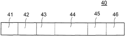
데이터 전송 프로세스는 확인 응답 패킷으로 구성된 미리 결정된 프로토콜에 따라 수행된다. 사용되기 위한 프로토콜의 가능한 응용이 그림4에 나와 있다. 프로토콜의 특징은 모든 패키지들이 시작 심볼(starting symbol)(41), 종료 심볼(ending symbol)(46)을 가지고, 전송 중에 패키지의 손상 가능성을 피하기 위하여 패키지의 타입을 식별하기 위한 필드(field for identifying the type of package)(42), 패키지 길이 필드(package length field)(43), 데이터 블록(data block)(44) 및 검증 합계 패키지(verification sum of the package)(45)의 사이에 있는 것이다. 향후 개발을 고려할 때 프로토콜은 패키지의 데이터 블록에 포함된 패키지의 해석을 지원하므로 구조가 쉽게 수정 가능하다.The data transfer process is performed according to a predetermined protocol configured as an acknowledgment packet. A possible application of the protocol to be used is shown in Figure 4. The protocol is characterized in that all packages have a starting symbol (41), an ending symbol (46), and a field for identifying the type of package to avoid possible package corruption during transmission the type of
도5는 컴퓨팅 장치(2)와 사용자의 휴대용 장치(1) 사이의 무선 데이터 및 에너지 전송 연결을 나타낸다. 도면에서 명확하게 알 수 있는 바와 같이, 컴퓨팅 장치(2)와 휴대용 장치(1)는 2개의 장치가 서로 충분히 근접하자마자 무선 인터페이스에 속하는 유도성 엘리먼트(안테나)를 통해 유도 결합 상태가 된다. 성공적인 데이터 및 에너지 전송을 위한 최대 거리는 적용되는 무선 기술에 의해 결정된다. NFC 기술의 경우 최대 거리는 1-2cm이며, BLE의 경우 최대 1m까지 가능하다. 그러나 NFC를 적용하는 경우, 두 유도 장치의 유도 부분을 최대한 가깝게 접근시키는 것이 바람직하며, 예를 들어 두 장치의 접촉에 의해 이루어질 수 있다. 효과를 더욱 향상시키기 위해 두 장치는 유도 엘리먼트가 가능한 가깝게 서로 접촉해야 한다. 이 위치 및 이 위치로부터의 임의의 편차는 컴퓨팅 장치에서 실행중인 어플리케이션에 의해 결정될 수 있으며 사용자에게 신호 보내질 수 있다. 컴퓨팅 장치(2)에 의해 전송되고 휴대용 장치(1)에 의해 수신된 데이터는 휴대용 장치(1)의 AFE 아날로그 프론트 엔드 유닛(AFE analogue front end unit)(1A)에 위치되고 제어 유닛(1E)에 전송되는 변조/복조 유닛(modulator/demodulator)(1C)에 의해 변환된다. 전송 중에 수신된 고주파 신호의 에너지는 정류기(1B)에 의해 정류되고, LDO 유닛(1D)은 그것을 전자 기기에 대한 조정된 DC 전압으로 변환한다.Fig. 5 shows the wireless data and energy transfer connection between the
인덕터는 표준 NFC 13.46MHz 주파수로 설정되며 아날로그 프런트 엔드 유닛(1A)에 연결된다. 가장 큰 가능한 에너지 전송을 위해, 전송 동안에 인덕터("안테나")는 사용자에 의해 사용자의 컴퓨팅 장치(2)의 인덕터("안테나")에 근접해야 한다. 데이터 및 에너지 전송은 인덕터들의 유도 결합을 통해 이루어진다. 인덕터로부터의 신호는 다이오드 브리지 정류기로 흐르므로 전계 강도(HV)에 따라 DC 전압이 발생한다. 인덕터는 데이터 전송을 용이하게 하고 NFC 표준 및 양방향 통신에 따라 신호의 변조/복조를 수행하는 블록(1C)에 연결된다. HV 지점에서 사용 가능한 에너지는 추가 유닛들에 의해 사용될 수 있으며 선형 LDO(Low Drop Out Voltage Regulator)(1D)를 통해 내부 디지털 처리 유닛(제어 유닛)(1E)의 전원 공급을 보장한다. 디지털 프로세싱 유닛은 NFC 표준에 의해 결정된 신호들의 변환 및 주변(I/O)을 통한 외부 세계로의 이러한 신호들의 버퍼링을 수행한다.The inductor is set to the standard NFC 13.46MHz frequency and is connected to the analog front-end unit (1A). For the greatest possible energy transfer, the inductor ("antenna") during transmission must be close to the inductor ("antenna") of the user's
도6은 휴대용 장치(1)의 동작을 위해 요구되는 전원 공급 전압을 생성하는 파워 서플라이의 블록 다이어그램을 개략적으로 나타낸다. 도시된 구성에서 인가된 디스플레이(e-잉크 페이퍼)는 상이한 전압을 필요로 하기 때문에, 파워 서플라이(12)는 이에 따라 스위치 모드 파워 서플라이(12a) 및 전하 펌프 전기 회로(charge pump electric circuits)(12b 및 12c)를 포함한다. 이 파워 서플라이(12)로 Vcc 입력 전압으로부터 6개의 상이한 출력 전압(V1-V6)이 생성될 수 있다.6 schematically shows a block diagram of a power supply for generating the power supply voltage required for the operation of the
NFC 통신 구현의 경우에, 도7에 도시된 에너지 저장 유닛(13)은 크게 두 부분으로 나누어질 수 있다. 첫 번째 부분은 입력에서 수신된 HV 전압을 배수로 변환하는 고효율 SMPS 스위치 모드 파워 서플라이(13a)이다. HV 지점에서 전압의 크기와 복구 가능한 전류는 동적으로 변화하므로 복구 가능한 에너지의 양은 연결 품질에 크게 의존한다. 이러한 품질 파라미터는 주로 연결의 두 장치(1 및 2)의 상대 거리, 위치 및 방향에 의해 결정된다. 파워 서플라이의 주된 특징은 가장 많은 에너지를 회수하기 위하여 상황 변화에 관계없이 고출력 임피던스 파워 서플라이(예를 들어, 광전지)의 경우에 일반적으로 적용되는 소위 MPPC(Maximum Power Point Control) 기술을 기반으로 하는 고효율 스위치 모드 파워 서플라이를 사용한다는 것이다. 이는 입력 전압이 소정 값 아래로 떨어지지 않는 방식으로 전류 수집을 제어하는 ?파워 서플라이 유닛(13a)에 의해 달성되며, 이러한 방식으로 주어진 전류 레벨에서 최대 전류가 회수될 수 있다. 스위치 모드 파워 서플라이 유닛(13a)은 에너지 저장 유닛(13b)에 에너지를 저장하기 위하여 이 입력 에너지를 사용한다. 파워 서플라이의 실제 구현은 인덕터(예를 들어, 승압 컨버터)를 기반으로 할 수 있고, 또는 콘덴서들만을 사용할 수도 있다(소위 펌프 충전 기반).In the case of the NFC communication implementation, the
스위치 모드 파워 서플라이의 가능한 구성이 도8에 나타나 있다. 파워 서플라이 유닛을 제어하는 제어 유닛(8d)의 필요 전압은 LDO(8c)에 의해 파워 서플라이 유닛(8e)의 입력단의 전원 전압으로부터 생성된다. 파워 서플라이 입력 전압의 요구되는 최소 레벨을 유지하기 위해, 분압기 회로(voltage divider circuit)(8a)가 제어 유닛(8d)에 대한 제어 신호를 제공하기 위해 인가되며, 제어 유닛(8d)은 이 제어 신호에 기초하여 입력에서 사용 가능한 에너지(예를 들어, 평균 전류 모드 제어, 피크 전류 모드 제어 등)에 따라 작동하는 동안 복구된 전류를 최대화하는 방식으로 DC-DC 컨버터의 작동을 제어할 수 있다. 출력 전압을 특정 레벨로 조정하기 위해, 또 다른 분압기 회로(8b)가 적용될 수 있다.A possible configuration of the switched mode power supply is shown in FIG. The required voltage of the
NFC 구현의 경우, 스위치 모드 파워 서플라이 유닛(13a)의 출력은 제어 유닛(15)에 의해 개별적으로 조작될 수 있는 병렬 연결된 다수의 저장 엘리먼트들 또는 셀들로 구성된 에너지 저장 유닛(13b)의 입력에 직접 연결되어, 저장 유닛의 저장 용량을 수정할 수 있고, 팔찌의 그래픽 변경에 필요한 에너지만 저장되도록 할 수 있다. 콘덴서 C1-Cn, 슈퍼 커패시터, 리튬 콘덴서 등이 에너지 저장 셀로 적용될 수 있다. 에너지 저장 셀은 병렬로 연결되며, 전형적으로 트랜지스터들을 스위칭하는 스위치(K1-Kn)에 의해 단계적으로 개별적으로 스위칭될 수 있다. 스위치가 꺼지면 해당 에너지 저장 셀은 에너지 저장에 참여하지 않는다. 이것은 필요한 에너지에 따라 에너지 저장 유닛의 용량을 동적으로 변경할 수 있게 한다. 제어 유닛(15)은 분압기 회로(91)를 통해 에너지 저장 유닛 내의 누적된 에너지에 대한 피드백을 수신한다.In the case of an NFC implementation, the output of the switched mode
디스플레이의 그래픽 변경에 필요한 에너지는 다른 파라미터들을 고려하여 제어 유닛에 의해 결정된다. 이러한 파라미터들은 디스플레이의 그래픽 유형, 디스플레이되기 위한 새로운 그래픽, 색상 범위(흑백 또는 그레이 스케일) 등이다. 정확한 피드백(precise feedback)은 에너지 저장 셀의 에너지 레벨에서 분압기에 의해 제어 유닛(15)으로 보내지고, 제어 유닛이 충분한 에너지가 디스플레이상의 그래픽의 변화에 대해 누적되었는지 여부를 결정하는 것에 기초한다.The energy required for the graphical change of the display is determined by the control unit in consideration of the other parameters. These parameters include the graphics type of the display, new graphics to be displayed, color gamut (black and white or grayscale), and so on. The precise feedback is sent by the voltage divider to the
무선 통신 채널이 NFC 대신에 BLE 기술에 의해 구현되는 경우, 에너지 저장 모듈(13)은 무선 인터페이스 유닛(14)에 의해 충전이 조절될 수 있는 축전지일 수있다.When the wireless communication channel is implemented by BLE technology instead of NFC, the
도10은 분해된 축척도(axonometric drawing) - 동적으로 변경 가능한 그래픽을 가지는 휴대용 장치(팔찌)(1)의 구조를 나타낸다. 팔찌는 구조적으로 하나의 부품으로 구성되거나 더 많은 부품을 함께 장착할 수 있는 금속 프레임 워크를 가진다. 후자의 경우 금속 부품은 플라스틱 캐리어 프레임에 부착된다. 캐리어 프레임은 바람직하게는 통합 전자 장치(C) 및 프레임(A)에 위치하는 휘어질 수 있거나 곡선형 디스플레이(B)를 포함하도록 구성되고, 전자 장치(C)는 밀봉(D) 백 시트에 의해 덮인다. 팔찌의 작동에 필요한 전자 장치가 디스플레이에 필요한 필수 구성 요소를 포함하도록 구성된 가요성 인쇄 회로 기판에 장착되므로, 디스플레이(B) 제조시 활용되며 분리할 수 없는 부분이 된다.Fig. 10 shows the structure of a portable device (bracelet) 1 having an axonometric drawing-dynamically changeable graphic. Bracelets are structurally made of one part or have a metal framework that can be fitted with more parts together. In the latter case, the metal parts are attached to the plastic carrier frame. The carrier frame is preferably configured to include an integrated electronic device C and a curved display B positioned in frame A and the electronic device C is configured to be movable between a closed (D) Cover. Since the electronic device necessary for the operation of the bracelet is mounted on a flexible printed circuit board configured to include the necessary components necessary for the display, it becomes an inseparable part which is utilized in manufacturing the display (B).
마지막으로, 도11은 디스플레이에 두 개의 상이한 그래픽들을 가지는 팔찌로 제조된 휴대용 장치의 예를 나타낸다. 본 발명은 도면에 도시된 실시 예에 따라 상세하게 설명되었다. 그러나, 이는 본 발명이 이들 실시 예들에 한정되는 것을 의미하지는 않는다. 당업자에게는 자명할 수 있는 바와 같이, 본 발명의 청구 범위에 의해 결정되는 보호 범위 내에서 수 많은 다른 변형들 및 조합들이 존재한다. 예를 들어, 사용자의 컴퓨팅 장치는 원격, 로컬 또는 무선 네트워크 연결을 설정할 수 있는 임의의 장치(예를 들어, PC, NFC 작성기 등)일 수 있다.Finally, FIG. 11 shows an example of a portable device made of a bracelet having two different graphics on a display. The present invention has been described in detail in accordance with the embodiment shown in the drawings. However, this does not mean that the present invention is limited to these embodiments. As will be apparent to those skilled in the art, there are many other variations and combinations within the scope of protection as determined by the claims of the present invention. For example, the user's computing device may be any device (e.g., a PC, an NFC writer, etc.) capable of establishing a remote, local or wireless network connection.
1 : 휴대용 장치 2 : 컴퓨팅 장치1: Portable device 2: Computing device
Claims (11)
이미지 정보는 그 자체의 에너지원 및 무선 통신 채널(5)을 가지는 사용자의 컴퓨팅 장치에서 가능하고,
- 상기 휴대용 장치(1)는 두 장치들 사이의 통신 및/또는 에너지의 흐름을 허용하는 거리 내에서 컴퓨팅 장치(2)에 근접하여 배치되고,
- 필요하다면, 상기 컴퓨팅 장치(2)로부터 상기 휴대용 장치(1)로 에너지가 전송되고,
- 전송된 에너지는 상기 휴대용 장치(1)에 저장되고(일시적으로),
- 이미지 정보는 상기 무선 통신 채널을 통해 상기 컴퓨팅 장치(2)로부터 상기 휴대용 장치(1)로 전송되고, 그리고
- 전송된 이미지 정보가 상기 휴대용 장치(1)의 상기 디스플레이(11)에 나타나고,
또한, 본 발명에 따른 프로세스에서,
- 전송된 이미지 정보는 또한 상기 휴대용 장치(1)에 저장되고,
- 저장된 이미지 정보에 기초하여, 디스플레이된 이미지의 변경을 위한 충분한 양의 에너지가 계산되고,
- 필요하다면, 필요한 양의 에너지가 상기 컴퓨팅 장치(2)로부터 상기 휴대용 장치(1)로 전송되고,
- 전송된 에너지는 상기 휴대용 장치에 저장되고, 그리고
- 디스플레이된 이미지의 변경이 상기 휴대용 장치에서 수행되는 것
을 특징으로 하는 이미지 정보를 전송 및 디스플레이하는 방법.
1. A method for transmitting and displaying image information on a display (11) of a portable device (1) having a rechargeable energy source and a wireless communication channel,
The image information is available at the user's computing device with its own energy source and wireless communication channel 5,
- the portable device (1) is placed close to the computing device (2) within a distance that allows communication and / or energy flow between the two devices,
- if necessary, energy is transferred from the computing device (2) to the portable device (1)
The transmitted energy is stored (temporarily) in the portable device 1,
Image information is transmitted from the computing device (2) to the portable device (1) via the wireless communication channel, and
- the transmitted image information appears on the display (11) of the portable device (1)
Further, in the process according to the present invention,
- the transmitted image information is also stored in the portable device (1)
- based on the stored image information, a sufficient amount of energy for the change of the displayed image is calculated,
- if necessary, a required amount of energy is transferred from the computing device (2) to the portable device (1)
The transmitted energy is stored in the portable device, and
≪ RTI ID = 0.0 > - < / RTI >
The method comprising the steps < RTI ID = 0.0 > of: < / RTI >
에너지 전송 중에 상기 휴대용 장치(1)는 최저 에너지 소비 모드(휴면 모드)에 놓이는 것을 특징으로 하는 이미지 정보를 전송 및 디스플레이하는 방법.
The method according to claim 1,
Characterized in that during energy transmission the portable device (1) is placed in a lowest energy consumption mode (sleep mode).
에너지 전송 동안에, 상기 휴대용 장치(1)는 미리 정해진 시간 주기 동안 정상 모드에 놓이게 되므로, 상기 휴대용 장치(1)의 전송되고 저장된 에너지가 디스플레이된 이미지를 변경하기에 충분한지를 체크하는 것이 가능한 것을 특징으로 하는 이미지 정보를 전송 및 디스플레이하는 방법.
3. The method of claim 2,
Characterized in that it is possible to check, during energy transfer, whether the transmitted and stored energy of the portable device (1) is sufficient to change the displayed image, since the portable device (1) is placed in the normal mode for a predetermined period of time And transmitting the image information.
디스플레이의 변경 동안, 휴대용 장치(1)의 저장부로부터 디스플레이(11)로 전송 되는데:
- 디스플레이된 이미지의 변경 및 새로 고침에 필요한 알고리즘을 수행하는 프로그램.
- 디스플레이된 이미지의 변경 및 새로 고침에 필요한 파라미터들 및
- 디스플레이되기 위한 이미지 정보가 전송되는 것
을 특징으로 하는 이미지 정보를 전송 및 디스플레이하는 방법.
The method according to claim 1,
During the change of the display, it is transmitted from the storage of the portable device 1 to the display 11:
- A program that performs the algorithms necessary to change and refresh the displayed image.
- parameters required for changing and refreshing the displayed image and
- image information to be displayed is transmitted
The method comprising the steps < RTI ID = 0.0 > of: < / RTI >
디스플레이된 이미지의 변경 또는 새로 고침에 필요한 파라미터들의 전송 동안, 실제 동작 조건들에 따른 범위들에 속하는 파라미터들만이 전송되는 것을 특징으로 하는 이미지 정보를 전송 및 디스플레이하는 방법.
5. The method of claim 4,
Wherein only parameters belonging to ranges according to actual operating conditions are transmitted during transmission of the parameters necessary for changing or refreshing the displayed image.
환경의 온도가 작동 조건으로서 결정되고 이에 기초하여, 이전에 결정된 온도 범위와 관련된 파라미터들 중, 결정된 온도 범위 내에 있는 파라미터들만이 전송되는 것을 특징으로 하는 이미지 정보를 전송 및 디스플레이하는 방법.
6. The method of claim 5,
Characterized in that the temperature of the environment is determined as the operating condition and, based thereon, only those parameters within the determined temperature range, among the parameters relating to the previously determined temperature range, are transmitted.
상기 무선 통신 채널은 NFC, 또는 블루투스 저에너지(BLE) 표준에 기초하는 통신 채널인 것을 특징으로 하는 이미지 정보를 전송 및 디스플레이하는 방법.
The method according to claim 1,
Wherein the wireless communication channel is a communication channel based on NFC, or a Bluetooth low energy (BLE) standard.
이미지 정보는 그 자체의 에너지원 및 상기 무선 통신 채널(5)을 가지는 사용자의 컴퓨팅 장치(2)에서 가능하며,
- 상기 무선 통신 채널을 통한 데이터 통신 및/또는 에너지 전송을 제공하기 위한 NFC 또는 BLE 송수신 유닛,
- 상호 유도적으로 결합되는 송수신 유닛들의 안테나들
을 포함하고,
상기 휴대용 장치(1)는,
- 프로그램, 데이터 및 에너지 저장 유닛.
- 전송된 이미지 정보를 저장하는 데이터 저장부
를 더 포함하고,
- 상기 에너지 저장 유닛(13)은 후자의 경우 병렬로 연결되고 켜지고 꺼질 수 있는 하나 이상의 에너지 저장 엘리먼트(들)을 포함하고, 영구적인 2차 에너지원을 포함하는 것을 특징으로 하는 이미지 정보를 전송 및 디스플레이하는 장치.
An apparatus for transmitting and displaying image information on a display (11b) of a portable device (1) having a rechargeable energy source and a wireless communication channel (5)
The image information is available in the user's computing device 2 having its own energy source and the wireless communication channel 5,
An NFC or BLE transceiver unit for providing data communication and / or energy transmission over the wireless communication channel,
Antennas of the transceiver units that are coupled inductively
/ RTI >
The portable device (1)
- Program, data and energy storage unit.
- a data storage unit
Further comprising:
Characterized in that the energy storage unit (13) comprises at least one energy storage element (s) connected in parallel and turned on and off in the latter case and comprises a permanent secondary energy source. Display device.
휴대용 장치(1)는 상기 디스플레이(11), 무선 송수신 유닛(14), 상기 프로그램, 상기 데이터 및 상기 에너지 저장 유닛에 부가하여 파워 서플라이(12) 및 제어 유닛(15)을 더 포함하며,
- 상기 에너지 저장 유닛(13)은 프로그램 가능한 토글 스위치(S3, S2)를 통해 상기 무선 송수신 유닛(14)과 상기 파워 서플라이(12)에 연결되며,
- 상기 파워 서플라이(12)는 프로그램 가능한 토글 스위치(S1)를 통해 상기 디스플레이(11)에 연결되고,
- 프로그램 가능한 토글 스위치(S1, S2, S3)는 상기 제어 유닛(15)에 의해 제어되는 것을 특징으로 하는 이미지 정보를 전송 및 디스플레이하는 장치.
9. The method of claim 8,
The portable device 1 further comprises a power supply 12 and a control unit 15 in addition to the display 11, the wireless transceiver unit 14, the program, the data and the energy storage unit,
The energy storage unit 13 is connected to the wireless transceiver unit 14 and the power supply 12 via programmable toggle switches S3 and S2,
- the power supply (12) is connected to the display (11) via a programmable toggle switch (S1)
Characterized in that the programmable toggle switches (S1, S2, S3) are controlled by the control unit (15).
상기 파워 서플라이(12)는 필요한 전력 공급 전압(들)을 발생시키기 위해 적어도 하나의 연결된 전하 펌프 전기 회로(12b, 12c)를 가진 스위치 모드 파워 서플라이인 것을 특징으로 하는 이미지 정보를 전송 및 디스플레이하는 장치.
10. The method of claim 9,
Characterized in that the power supply (12) is a switched mode power supply with at least one connected charge pump electrical circuit (12b, 12c) for generating the required power supply voltage (s) .
상기 휴대용 장치는 또한 작동 조건을 측정하기 위한 엘리먼트
를 포함하고,
상기 엘리먼트는 바람직하게는 온도 센서인 것을 특징으로 하는 이미지 정보를 전송 및 디스플레이하는 장치.11. The method according to any one of claims 8 to 10,
The portable device also includes an element for measuring operating conditions
Lt; / RTI >
Characterized in that the element is preferably a temperature sensor.
Applications Claiming Priority (5)
| Application Number | Priority Date | Filing Date | Title |
|---|---|---|---|
| HUP1500347 | 2015-07-27 | ||
| HUP1500347 | 2015-07-27 | ||
| HUP1600155 | 2016-02-29 | ||
| HU1600155A HUP1600155A2 (en) | 2016-02-29 | 2016-02-29 | Method and arrangement for transmitting and displaying image information |
| PCT/HU2016/000049 WO2017017481A1 (en) | 2015-07-27 | 2016-07-25 | Method and arrangement for transmitting and displaying image information |
Publications (1)
| Publication Number | Publication Date |
|---|---|
| KR20180033291A true KR20180033291A (en) | 2018-04-02 |
Family
ID=89992101
Family Applications (1)
| Application Number | Title | Priority Date | Filing Date |
|---|---|---|---|
| KR1020187005815A Withdrawn KR20180033291A (en) | 2015-07-27 | 2016-07-25 | Method and apparatus for transmitting and displaying image information |
Country Status (10)
| Country | Link |
|---|---|
| US (1) | US10085139B2 (en) |
| EP (1) | EP3329357A1 (en) |
| JP (1) | JP2018526966A (en) |
| KR (1) | KR20180033291A (en) |
| CN (1) | CN108139877A (en) |
| AU (1) | AU2016298778A1 (en) |
| CA (1) | CA2993483A1 (en) |
| IL (1) | IL257144A (en) |
| RU (1) | RU2018106946A (en) |
| WO (1) | WO2017017481A1 (en) |
Families Citing this family (8)
| Publication number | Priority date | Publication date | Assignee | Title |
|---|---|---|---|---|
| CN111383605A (en) * | 2018-12-28 | 2020-07-07 | 南京启纬智芯微电子有限公司 | Passive display device, communication method, active electronic terminal and storage medium |
| CN113131622A (en) * | 2019-12-31 | 2021-07-16 | 杭州启纬科技有限公司 | Portable display device, control method, wireless transmission system, and storage medium |
| CN111210753B (en) * | 2020-01-23 | 2023-06-09 | 京东方科技集团股份有限公司 | Display driving circuit, display driving method and display device |
| CN111506336A (en) * | 2020-03-19 | 2020-08-07 | 京东方科技集团股份有限公司 | Electronic ink screen updating method and related equipment |
| CN114787902B (en) * | 2020-09-29 | 2025-03-18 | 京东方科技集团股份有限公司 | Electronic ink screen control method, display control device and electronic ink display device |
| CN114945971B (en) * | 2020-10-29 | 2025-09-05 | 京东方科技集团股份有限公司 | Control method and display control device of electronic ink screen |
| CN112965678A (en) * | 2021-03-16 | 2021-06-15 | 广州文石信息科技有限公司 | Display, device, storage medium and method based on electronic ink screen |
| CN121640929A (en) * | 2026-02-05 | 2026-03-10 | 安徽煜图科技有限公司 | Electronic paper display equipment and feed protection and charging optimization method thereof |
Family Cites Families (9)
| Publication number | Priority date | Publication date | Assignee | Title |
|---|---|---|---|---|
| US20020167500A1 (en) * | 1998-09-11 | 2002-11-14 | Visible Techknowledgy, Llc | Smart electronic label employing electronic ink |
| AU2001268069A1 (en) * | 2000-05-19 | 2001-12-03 | Technology Innovations, Llc | Apparatus for the display of embedded information |
| US8079904B2 (en) * | 2004-08-20 | 2011-12-20 | Igt | Gaming access card with display |
| US7329186B2 (en) * | 2004-08-20 | 2008-02-12 | Igt | Gaming system with rewritable display card and LCD input display for reading same |
| US7270276B2 (en) * | 2004-09-29 | 2007-09-18 | Sap Ag | Multi-application smartcard |
| US7904277B2 (en) * | 2007-12-12 | 2011-03-08 | Motorola Mobility, Inc. | Labeling methods and devices |
| EP2810068B1 (en) * | 2012-02-03 | 2017-04-19 | Siemens Healthcare Diagnostics Inc. | Status displaying sample carrier |
| HK1207727A1 (en) * | 2012-09-21 | 2016-02-05 | Visa International Service Association | A dynamic object tag and systems and methods relating thereto |
| US20140267940A1 (en) | 2013-03-15 | 2014-09-18 | Nathan Ackerman | Low-power wearable electronic display device |
-
2016
- 2016-07-25 KR KR1020187005815A patent/KR20180033291A/en not_active Withdrawn
- 2016-07-25 WO PCT/HU2016/000049 patent/WO2017017481A1/en not_active Ceased
- 2016-07-25 RU RU2018106946A patent/RU2018106946A/en not_active Application Discontinuation
- 2016-07-25 CN CN201680056041.XA patent/CN108139877A/en not_active Withdrawn
- 2016-07-25 EP EP16763932.7A patent/EP3329357A1/en not_active Withdrawn
- 2016-07-25 CA CA2993483A patent/CA2993483A1/en not_active Abandoned
- 2016-07-25 AU AU2016298778A patent/AU2016298778A1/en not_active Abandoned
- 2016-07-25 JP JP2018524568A patent/JP2018526966A/en active Pending
-
2018
- 2018-01-25 US US15/879,657 patent/US10085139B2/en not_active Expired - Fee Related
- 2018-01-25 IL IL257144A patent/IL257144A/en unknown
Also Published As
| Publication number | Publication date |
|---|---|
| CN108139877A (en) | 2018-06-08 |
| JP2018526966A (en) | 2018-09-13 |
| CA2993483A1 (en) | 2017-02-02 |
| US20180152823A1 (en) | 2018-05-31 |
| US10085139B2 (en) | 2018-09-25 |
| WO2017017481A1 (en) | 2017-02-02 |
| IL257144A (en) | 2018-03-29 |
| AU2016298778A1 (en) | 2018-03-08 |
| EP3329357A1 (en) | 2018-06-06 |
| RU2018106946A (en) | 2019-08-27 |
Similar Documents
| Publication | Publication Date | Title |
|---|---|---|
| KR20180033291A (en) | Method and apparatus for transmitting and displaying image information | |
| US20230021065A1 (en) | Wireless Power System With Battery Charge Indicators | |
| EP3121706A1 (en) | Control method and control system for working mode of mobile device | |
| CN102801219B (en) | Electronic installation and control method thereof | |
| US9230427B2 (en) | Apparatus for low power wireless communication | |
| CN109904884B (en) | Wireless charging method, device, terminal, storage medium and electronic device | |
| CN111383605A (en) | Passive display device, communication method, active electronic terminal and storage medium | |
| CN107294187A (en) | electronic device charging system with display screen | |
| CN204406380U (en) | A kind of electronic ink screen label data distribution system | |
| CN115240290A (en) | Attendance card punching reminding method, intelligent wearable device and attendance card punching system | |
| KR20170010280A (en) | An accessory device with the payment card using NFC and bluetooth communication | |
| US12236150B2 (en) | Display interface switching method and apparatus, and wearable device body and wearable device | |
| CN104865872A (en) | Wearable electronic equipment and data interaction method thereof | |
| US9682008B2 (en) | Wetness controlling system and intelligent vibrator including the same | |
| US12026569B2 (en) | Display method of electronic identification device, controller, electronic identification device and system | |
| CN117335528A (en) | Fast charging charger and adjustment method for intelligently adjusting voltage and current | |
| CN204617257U (en) | A kind of wireless charging bracelet | |
| US10528080B2 (en) | Systems and methods for providing displays via a smart hand-strap accessory | |
| CN211744150U (en) | Portable display device and wireless transmission system | |
| CN209625261U (en) | A kind of electronic tag | |
| CN209928432U (en) | Hand-held type NFC read write line appearance | |
| WO2015190997A1 (en) | Radio communication devices and methods for controlling a radio communication device | |
| JP2012032953A (en) | Non-contact type wireless tag system, device, and power consumption reduction method | |
| CN222283530U (en) | Passive LED driving circuit, protective case of mobile terminal and passive LED system | |
| CN205103564U (en) | Children intelligent communication wrist -watch |
Legal Events
| Date | Code | Title | Description |
|---|---|---|---|
| PA0105 | International application |
Patent event date: 20180227 Patent event code: PA01051R01D Comment text: International Patent Application |
|
| PG1501 | Laying open of application | ||
| PC1203 | Withdrawal of no request for examination |