KR20180001467A - Hydraulic pump - Google Patents
Hydraulic pump Download PDFInfo
- Publication number
- KR20180001467A KR20180001467A KR1020170078289A KR20170078289A KR20180001467A KR 20180001467 A KR20180001467 A KR 20180001467A KR 1020170078289 A KR1020170078289 A KR 1020170078289A KR 20170078289 A KR20170078289 A KR 20170078289A KR 20180001467 A KR20180001467 A KR 20180001467A
- Authority
- KR
- South Korea
- Prior art keywords
- pressing
- swash plate
- hydraulic pump
- pin
- pressure
- Prior art date
- Legal status (The legal status is an assumption and is not a legal conclusion. Google has not performed a legal analysis and makes no representation as to the accuracy of the status listed.)
- Granted
Links
Images


Classifications
-
- F—MECHANICAL ENGINEERING; LIGHTING; HEATING; WEAPONS; BLASTING
- F04—POSITIVE - DISPLACEMENT MACHINES FOR LIQUIDS; PUMPS FOR LIQUIDS OR ELASTIC FLUIDS
- F04B—POSITIVE-DISPLACEMENT MACHINES FOR LIQUIDS; PUMPS
- F04B1/00—Multi-cylinder machines or pumps characterised by number or arrangement of cylinders
- F04B1/12—Multi-cylinder machines or pumps characterised by number or arrangement of cylinders having cylinder axes coaxial with, or parallel or inclined to, main shaft axis
- F04B1/26—Control
- F04B1/30—Control of machines or pumps with rotary cylinder blocks
- F04B1/32—Control of machines or pumps with rotary cylinder blocks by varying the relative positions of a swash plate and a cylinder block
- F04B1/324—Control of machines or pumps with rotary cylinder blocks by varying the relative positions of a swash plate and a cylinder block by changing the inclination of the swash plate
Landscapes
- Engineering & Computer Science (AREA)
- Mechanical Engineering (AREA)
- General Engineering & Computer Science (AREA)
- Reciprocating Pumps (AREA)
Abstract
간단한 기구에 의해 경사판의 틸팅각을 조정 가능한 유압 펌프를 제공한다.
유압 펌프(10)는, 회전 축선(A) 주위로 회전하고, 회전 축선(A) 방향을 따라서 연장되는 복수의 실린더 구멍(32)이 형성된 실린더 블록(30)과, 각 실린더 구멍(32) 내로 미끄럼 이동 가능하게 보유 지지된 피스톤(38)과, 실린더 블록(30)이 회전 축선(A) 주위로 회전함으로써, 각 피스톤(38)을 각 실린더 구멍(32) 내로 미끄럼 이동시키기 위한 경사판(40)이며, 그 틸팅각이 변경 가능하도록 구성된 경사판(40)과, 경사판(40)의 틸팅각이 커지는 방향으로 경사판(40)을 가압하는 제1 가압 수단(50)과, 경사판(40)의 틸팅각이 작아지는 방향으로 경사판(40)을 가압하는 제2 가압 수단(60)을 갖고, 제2 가압 수단(60)은, 가압 로드(61)와 복수의 가압 핀(71 내지 74)을 갖고, 각 가압 핀(71 내지 74)은, 각 가압 핀(71 내지 74)에 대응하는 신호압에 따라서 가압 로드(61)를 통해 경사판(40)을 가압한다.A hydraulic pump capable of adjusting a tilting angle of a swash plate by a simple mechanism is provided.
The hydraulic pump 10 includes a cylinder block 30 having a plurality of cylinder bores 32 extending around the axis of rotation A and extending along the direction of the axis of rotation A, A swash plate 40 for slidably moving each piston 38 into each cylinder hole 32 by rotating the cylinder block 30 about the axis of rotation A, A first pushing means 50 for pushing the swash plate 40 in a direction in which the tilting angle of the swash plate 40 is increased and a tilting angle of the swash plate 40, And the second pressing means 60 has a pressing rod 61 and a plurality of pressing pins 71 to 74, The pressing pins 71 to 74 press the swash plate 40 through the pressing rod 61 in accordance with signal pressures corresponding to the pressing pins 71 to 74 The.

Description
본 발명은, 건설 차량 등에 사용되는 유압 펌프에 관한 것이고, 특히 가변 용량형 유압 펌프에 관한 것이다.BACKGROUND OF THE INVENTION 1. Field of the Invention The present invention relates to a hydraulic pump used in a construction vehicle and the like, and more particularly to a variable displacement hydraulic pump.
건설 차량 등의 폭넓은 분야에 있어서, 가변 용량형 유압 펌프가 사용되고 있다. 가변 용량형 유압 펌프는, 일반적으로, 회전축 주위로 회전하고, 회전축 방향을 따라서 연장되는 복수의 실린더 구멍이 형성된 실린더 블록과, 각 실린더 구멍 내로 미끄럼 이동 가능하게 보유 지지된 피스톤과, 실린더 블록이 회전축 주위로 회전함으로써, 각 피스톤을 각 실린더 구멍 내로 미끄럼 이동시키기 위한 경사판과, 실린더 블록의 회전축에 대한 경사판의 경사각(틸팅각)을 변경하기 위한 기구를 갖고 있다.BACKGROUND ART Variable displacement hydraulic pumps have been used in a wide range of fields such as construction vehicles. The variable displacement type hydraulic pump generally includes a cylinder block having a plurality of cylinder holes formed around the rotation axis and extending along the rotation axis direction, a piston slidably held in each cylinder hole, And has a mechanism for changing the inclination angle (tilting angle) of the swash plate with respect to the rotation axis of the cylinder block.
예를 들어 특허 문헌 1에는, 경사판의 틸팅각을 바꿈으로써 토출 용량이 조정되는 가변 용량형 사판식 유압 펌프가 개시되어 있다. 특허 문헌 1에 개시된 사판식 유압 펌프는, 복수의 피스톤과, 피스톤을 수용하는 복수의 실린더를 갖는 실린더 블록과, 실린더 블록의 회전에 따라서 피스톤을 왕복 이동시키는 경사판과, 경사판을 틸팅각이 커지는 방향으로 가압하는 가압 수단과, 직접 원통 형상으로 형성되며 이너 가이드 실린더와 아우터 가이드 실린더의 사이에 미끄럼 이동 가능하게 삽입된 제1 제어 핀, 바닥이 있는 원통 형상으로 형성되며 아우터 가이드 실린더의 외측에 미끄럼 이동 가능하게 감합된 제2 제어 핀을 갖고 있다. 이 사판식 유압 펌프에서는, 제1 제어 핀이, 그 수압면에 받는 서브의 피스톤 펌프 토출압(제1 부하압)이 높아짐에 따라서 경사판을 향해 이동하고, 제2 제어 핀이, 그 수압면에 받는 파일럿압(제2 부하압)이 높아짐에 따라서 경사판을 향해 이동함으로써, 경사판의 틸팅각을 작게 할 수 있도록 되어 있다.For example, Patent Document 1 discloses a variable displacement swash plate type hydraulic pump in which a discharge capacity is adjusted by changing a tilting angle of a swash plate. The swash plate type hydraulic pump disclosed in Patent Document 1 includes a cylinder block having a plurality of pistons, a plurality of cylinders accommodating the pistons, a swash plate reciprocating the piston in accordance with the rotation of the cylinder block, and a swash plate reciprocating in a direction A first control pin formed in a straight cylindrical shape and slidably inserted between the inner guide cylinder and the outer guide cylinder, a second control pin formed in a cylindrical shape having a bottom, and slidable on the outer side of the outer guide cylinder Lt; RTI ID = 0.0 > controllably < / RTI > In this swash plate type hydraulic pump, the first control pin moves toward the swash plate as the sub piston piston discharge pressure (first load pressure) received on the hydraulic pressure surface increases, and the second control pin moves on the hydraulic pressure surface The tilting angle of the swash plate can be reduced by moving toward the swash plate as the received pilot pressure (second load pressure) becomes higher.
특허 문헌 1에 개시된 기술에서는, 토출압이나 파일럿압이 부하된 오일이, 제1 제어 핀과 이너 가이드 실린더 및 아우터 가이드 실린더의 사이나, 제2 제어 핀과 아우터 가이드 실린더의 사이에서 누설되는 일이 없도록, 제1 제어 핀의 내외면 및 제2 제어 핀의 내면에 연마 처리 등의 마무리 가공을 행하는 것이 불가결하다. 그러나, 특히 부재의 내면에 대한 연마 처리 등의 마무리 가공은 기술적인 곤란을 수반하여, 가공에 소요되는 비용 및 시간이 증대된다는 문제가 있다.In the technique disclosed in Patent Document 1, the oil to which the discharge pressure or the pilot pressure is loaded is leaked between the first control pin and the inner guide cylinder and the outer guide cylinder, or between the second control pin and the outer guide cylinder It is indispensable to finish the inner and outer surfaces of the first control pin and the inner surface of the second control pin such as a polishing process. However, in particular, the finishing process such as the grinding process on the inner surface of the member is accompanied with a technical difficulty, and thus there is a problem that the cost and time required for machining are increased.
또한, 특허 문헌 1에 개시된 기술은, 1개의 펌프로 2개의 펌프의 기능을 갖는, 소위 스플릿 플로우 구조의 유압 펌프에는 대응하고 있지 않다. 또한, 유압 펌프에 있어서는, 디젤 엔진 등의 구동원의 출력 범위 내에서 유압 펌프를 제어하는 정마력 제어를 행할 필요가 있다. 그러나, 특허 문헌 1에 개시된 기술에서는, 동일한 구동원으로 구동되는 다른 펌프의 수가 증가된 경우, 각 제어 핀의 구조가 한층 복잡화되는 것이 예상된다. 또한, 특허 문헌 1에 개시된 기술에서는, 동일한 구동원으로 에어컨 등의 외부 기기가 구동되는 경우의 유압 펌프 제어에 대해서는 고려되고 있지 않다.The technique disclosed in Patent Document 1 does not cope with a so-called split flow structure hydraulic pump having the function of two pumps by one pump. Further, in the hydraulic pump, it is necessary to perform rigid power control for controlling the hydraulic pump within the output range of the drive source of the diesel engine or the like. However, in the technique disclosed in Patent Document 1, when the number of other pumps driven by the same drive source is increased, the structure of each control pin is expected to be further complicated. Further, the technique disclosed in Patent Document 1 does not consider the control of the hydraulic pump when an external device such as an air conditioner is driven by the same drive source.
본 발명은 이러한 점을 고려하여 이루어진 것이며, 간단한 기구에 의해 경사판의 틸팅각을 조정 가능한 유압 펌프를 제공하는 것을 목적으로 한다.SUMMARY OF THE INVENTION It is an object of the present invention to provide a hydraulic pump capable of adjusting a tilting angle of a swash plate by a simple mechanism.
본 발명에 의한 유압 펌프는,In the hydraulic pump according to the present invention,
회전 축선 주위로 회전하고, 상기 회전 축선 방향을 따라서 연장되는 복수의 실린더 구멍이 형성된 실린더 블록과,A cylinder block having a plurality of cylinder holes formed around the rotation axis and extending along the rotation axis direction;
각 실린더 구멍 내로 미끄럼 이동 가능하게 보유 지지된 피스톤과,A piston slidably held in each cylinder bore,
상기 실린더 블록이 상기 회전 축선 주위로 회전함으로써, 각 피스톤을 각 실린더 구멍 내로 미끄럼 이동시키기 위한 경사판이며, 그 틸팅각이 변경 가능하도록 구성된 경사판과,A swash plate for slidably moving the respective pistons into the respective cylinder bores by rotating the cylinder block around the rotation axis,
상기 경사판을 그 틸팅각이 커지는 방향으로 가압하는 제1 가압 수단과,A first pressing means for pressing the swash plate in a direction in which the tilting angle increases,
상기 경사판을 그 틸팅각이 작아지는 방향으로 가압하는 제2 가압 수단을 갖고,And second pressing means for pressing the swash plate in a direction in which the tilting angle is reduced,
상기 제2 가압 수단은, 가압 로드와 복수의 가압 핀을 갖고, 각 가압 핀은, 각 가압 핀에 대응하는 신호압에 따라서 상기 가압 로드를 통해 상기 경사판을 가압한다.The second pressing means has a pressing rod and a plurality of pressing pins, and each pressing pin presses the swash plate through the pressing rod in accordance with a signal pressure corresponding to each pressing pin.
본 발명에 의한 유압 펌프에 있어서, 상기 가압 로드의 측면을 가이드하는 가이드부를 더 가져도 된다.The hydraulic pump according to the present invention may further include a guide portion for guiding a side surface of the pressing rod.
본 발명에 의한 유압 펌프에 있어서, 상기 실린더 블록 및 상기 경사판을 수용하는 케이싱을 더 갖고, 상기 가이드부는, 상기 케이싱과 일체로 설치되어 있어도 된다.The hydraulic pump according to the present invention may further include a casing that receives the cylinder block and the swash plate, and the guide portion may be provided integrally with the casing.
본 발명에 의한 유압 펌프에 있어서, 상기 복수의 가압 핀 중 적어도 1개는 예비용 가압 핀이어도 된다.In the hydraulic pump according to the present invention, at least one of the plurality of pressing pins may be a spare pressing pin.
본 발명에 의한 유압 펌프에 있어서, 상기 복수의 가압 핀 중 적어도 1개는 토출 작동유 유량 조정용 가압 핀이어도 된다.In the hydraulic pump according to the present invention, at least one of the plurality of pressing pins may be a pressing pin for adjusting the flow rate of the discharge hydraulic fluid.
본 발명에 따르면, 간단한 기구에 의해 경사판의 틸팅각을 조정 가능한 유압 펌프를 제공할 수 있다.According to the present invention, it is possible to provide a hydraulic pump capable of adjusting the tilting angle of the swash plate by a simple mechanism.
도 1은, 본 발명에 의한 일 실시 형태를 설명하기 위한 도면이며, 유압 펌프의 단면을 도시한 도면이다.
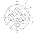
도 2는, 도 1의 II-II선에 대응하는 단면을 도시한 도면이다.
도 3은, 유압 펌프의 일 변형예를 도시한 단면도이다.
도 4는, 유압 펌프의 다른 변형예를 도시한 단면도이다.1 is a view for explaining an embodiment according to the present invention, and is a view showing a cross section of a hydraulic pump.
Fig. 2 is a cross-sectional view corresponding to line II-II in Fig. 1. Fig.
3 is a cross-sectional view showing a modified example of the hydraulic pump.
4 is a cross-sectional view showing another modification of the hydraulic pump.
이하, 도면을 참조하여 본 발명의 일 실시 형태에 대하여 설명한다. 또한, 본 명세서에 첨부하는 도면에 있어서는, 도시와 이해 용이성의 편의상, 적절히 축척 및 종횡의 치수비 등을, 실물의 그것들로부터 변경하고 과장되어 있다.Hereinafter, one embodiment of the present invention will be described with reference to the drawings. In addition, in the drawings attached to this specification, dimensions and aspect ratios are appropriately changed and exaggerated from the actual ones for convenience of illustration and ease of understanding.
또한, 본 명세서에 있어서 사용되는, 형상이나 기하학적 조건 및 그것들의 정도를 특정하는, 예를 들어 「평행」, 「직교」, 「동일」 등의 용어나 길이나 각도의 값 등에 대해서는, 엄밀한 의미에 매이지 않고, 동일한 기능을 기대할 수 있는 정도의 범위를 포함하여 해석하기로 한다.It should be noted that the terms "parallel", "orthogonal", "same", and the like, and the values of the length and the angle, which specify the shape and the geometrical condition and their degree, We shall interpret it as including the extent to which we can expect the same function without hanging.
도 1 내지 도 4는, 본 발명에 의한 일 실시 형태를 설명하기 위한 도면이다. 이 중 도 1은, 유압 펌프의 단면을 도시한 도면이며, 도 2는, 도 1의 II-II선에 대응하는 단면을 도시한 도면이다.Figs. 1 to 4 are views for explaining an embodiment according to the present invention. Fig. FIG. 1 is a cross-sectional view of the hydraulic pump, and FIG. 2 is a cross-sectional view taken along the line II-II in FIG.
본 실시 형태의 유압 펌프(10)는, 소위 사판식 가변 용량형 유압 펌프이다. 유압 펌프(10)는, 후술하는 실린더 구멍(32)으로부터의 작동유의 토출(및 실린더 구멍(32)으로의 작동유의 공급)에 기초하는 구동력을 출력한다. 보다 구체적으로는, 엔진 등의 동력원으로부터의 동력에 의해 회전축(25)을 회전시킴으로써, 회전축(25)과 스플라인 결합 등에 의해 결합된 실린더 블록(30)을 회전시켜, 실린더 블록(30)의 회전에 의해 피스톤(38)을 왕복 작동시킨다. 이 피스톤(38)의 왕복 작동에 따라서, 일부의 실린더 구멍(32)으로부터는 작동유가 토출되는 동시에 다른 실린더 구멍(32)에는 작동유가 흡입되어, 유압 펌프가 실현된다.The
도 1에 도시된 유압 펌프(10)는, 하우징(20), 회전축(25), 실린더 블록(30), 경사판(40), 제1 가압 수단(50) 및 제2 가압 수단(60)을 갖고 있다.1 includes a housing 20, a
하우징(20)은, 제1 하우징 블록(21)과, 제1 하우징 블록(21)의 일단부측에 결합된 제2 하우징 블록(22)을 갖고 있다. 하우징(20)은, 회전축(25)의 일부, 실린더 블록(30), 경사판(40) 및 제1 가압 수단(50)을 수용하고 있다. 도 1에 도시된 예에서는, 제1 하우징 블록(21)의 내측에, 회전축(25)의 한쪽 단부와, 흡배(吸排) 플레이트(35)를 통해 복수의 실린더 구멍(32)에 연통되는 도시하지 않은 공급 포트 및 배출 포트와, 후술하는 가압 로드(61)를 가이드하기 위한 제1 가이드부(23)가 배치되어 있다. 또한 공급 포트는, 제1 하우징 블록(21)을 관통하여 설치되고, 유압 펌프(10)의 외부에 설치되는 유압원(탱크)으로 연통된다. 제2 하우징 블록(22)에는, 회전축(25)이 관통하는 회전축용 구멍(24)이 형성되고, 회전축(25)은, 회전축용 구멍(24)에 있어서 베어링(28a)에 의해 회전 가능하게 지지되며, 회전축용 구멍(24)으로부터 외측을 향해 돌출되어 있다.The housing 20 has a first housing block 21 and a second housing block 22 coupled to one end of the first housing block 21. The housing 20 accommodates a part of the
회전축(25)은, 회전 축선(A)이 연장되는 방향으로 연장되고, 실린더 블록(30) 및 경사판(40)을 관통하여, 일단부가 제2 하우징 블록(22)의 회전축용 구멍(24)으로부터 외측으로 돌출되는 동시에, 타단부가 제2 하우징 블록(22)의 내측으로부터 제1 하우징 블록(21)의 내측으로 돌출되어 있다. 도 1에 도시된 예에서는, 회전축(25)은, 실린더 블록(30)을 관통하는 부분에 설치된 스플라인 결합부(26a)에 있어서 실린더 블록(30)과 스플라인 결합되어 있다. 이 실린더 블록(30)과의 스플라인 결합에 의해 회전축(25)은, 회전 축선(A)의 방향에 대해서는 실린더 블록(30)과 무관계로 이동 가능하지만, 회전 축선(A) 둘레의 회전 방향에 대해서는 실린더 블록(30)과 함께 일체적으로 회전한다. 또한 회전축(25)은, 제1 하우징 블록(21) 내에 있어서 베어링(28b)에 의해 회전 가능하게 지지되고, 제2 하우징 블록(22) 내에 있어서 베어링(28a)을 통해 회전 가능하게 지지되며, 경사판(40)과는 접촉하지 않도록 되어 있다. 따라서, 회전축(25)은, 실린더 블록(30) 이외의 부재에 의해서는 저해되지 않고, 실린더 블록(30)과 함께 회전 축선(A) 둘레의 회전 방향으로 회전 가능하게 설치되어 있다. 또한, 도시된 예에서는, 회전축(25)의, 회전축용 구멍(24)으로부터 외측으로 돌출된 일단부는, 스플라인 결합부(26b)를 통해 엔진 등의 동력원과 결합된다.The
실린더 블록(30)은, 회전축(25)과 함께 회전 축선(A)을 중심으로 회전하고, 회전 축선(A)의 주위에 있어서 회전 축선(A)과 평행한 방향을 따라서 뚫어 형성된 복수의 실린더 구멍(32)을 갖는다. 실린더 블록(30)에 형성되는 복수의 실린더 구멍(32)의 수는 특별히 한정되지 않지만, 이들 실린더 구멍(32)은, 회전 축선(A)에 따른 방향으로부터 보아, 동일 원주 상에 등간격으로 배치되는 것이 바람직하다.The
실린더 블록(30) 중 경사판(40)이 설치되는 측과는 반대측 단부, 복수의 실린더 구멍(32) 각각에 연통되는 개구(32a)가 형성되어 있다. 또한 실린더 블록(30) 중 경사판(40)이 설치되는 측과는 반대측 단부에 대면하여, 도시하지 않은 복수의 관통 구멍이 형성된 흡배 플레이트(35)가 배치되어 있다. 복수의 실린더 구멍(32)은, 이들의 개구(32a) 및 관통 구멍을 통해, 제1 하우징 블록(21) 내에 설치된 도시하지 않은 공급 포트 및 배출 포트와 연통되고, 이들 공급 포트 및 배출 포트를 통해 작동유의 공급 및 배출이 행해진다. 또한, 도 1에 도시된 예에서는, 실린더 블록(30) 중 경사판(40)이 설치되는 측과는 반대측 단부의 회전축(25) 주위에, 후술하는 스프링(44) 및 리테이너(45a, 45b)를 수용하는 오목부(30a)가 형성되어 있다.An opening 32a communicating with each of the plurality of
도 1에 도시된 흡배 플레이트(35)는, 제1 하우징 블록(21)에 고정되어 있고, 실린더 블록(30)이 회전축(25)과 함께 회전하는 경우에도, 하우징(20)(제1 하우징 블록(21))에 대하여 정지되어 있다. 그 때문에, 공급 포트 및 배출 포트의 각각과 연통되는 실린더 구멍(32)은, 실린더 블록(30)의 회전 상태에 따라서 흡배 플레이트(35)를 통해 전환되어, 공급 포트로부터 작동유가 공급되는 상태와 배출 포트로 작동유를 배출하는 상태가 반복해서 찾아온다.1 is fixed to the first housing block 21. Even when the
피스톤(38)은, 각각 대응하는 실린더 구멍(32)에 대하여 미끄럼 이동 가능하게 배치되어 있다. 바꾸어 말하면, 피스톤(38)은, 각각 대응하는 실린더 구멍(32) 내로 미끄럼 이동 가능하게 유지되어 있다. 특히, 각 피스톤(38)은, 대응하는 실린더 구멍(32)에 대하여 회전 축선(A)과 평행한 방향을 따라서 왕복 이동 가능하게 설치되어 있다. 피스톤(38)의 내부는 공동이며, 실린더 구멍(32) 내의 작동유로 채워져 있다. 따라서 피스톤(38)의 왕복 이동은 실린더 구멍(32)으로의 작동유의 공급 및 배출과 연관되고, 피스톤(38)이 실린더 구멍(32)으로부터 인출될 때에는, 실린더 구멍(32) 내에 공급 포트로부터 작동유가 공급되며, 피스톤(38)이 실린더 구멍(32) 내에 진입할 때에는, 실린더 구멍(32) 내로부터 배출 포트로 작동유가 배출된다.The
본 실시 형태에서는, 각 피스톤(38)의 경사판(40)측 단부(실린더 구멍(32)으로부터 돌출되는 측의 단부)에는, 슈(43)가 설치되어 있다. 또한, 회전축(25)의 주위에는, 스프링(44), 리테이너(45a, 45b), 연결 부재(46), 가압 부재(47) 및 슈 유지 부재(48)가 설치되어 있다. 스프링(44) 및 리테이너(45a, 45b)는, 실린더 블록(30) 중 경사판(40)이 설치되는 측과는 반대측 단부의 회전축(25) 주위에 형성된 오목부(30a) 내에 수용되어 있다. 도 1에 도시된 예에서는, 스프링(44)은 코일 스프링이며, 오목부(30a) 내에 있어서, 리테이너(45a)와 리테이너(45b)의 사이에 압축된 상태에서 배치되어 있다. 따라서, 스프링(44)은, 그 탄성력에 의해 당해 스프링(44)이 신장되는 방향으로 가압력을 발생한다. 스프링(44)의 가압력은 리테이너(45b) 및 연결 부재(46)을 통해 가압 부재(47)에 전달된다. 슈 유지 부재(48)에는, 각 슈(43)가 유지되고 있으며, 가압 부재(47)은 스프링(44)의 가압력을 받아, 슈 유지 부재(48)를 통해 각 슈(43)를 경사판(40)을 향해 가압한다.In the present embodiment, a
도 1에 도시된 예에서는, 경사판(40)은 다양한 각도로 틸팅 가능하지만, 스프링(44)의 가압력에 의해, 경사판(40)의 틸팅각에 관계없이 각 슈(43)가 경사판(40)에 대하여 적절하게 추종하여 가압된다. 이에 의해, 피스톤(38)이 실린더 블록(30)과 함께 회전하면, 각 슈(43)는 경사판(40) 상에서 원 궤도를 그리도록 하여 미끄럼 이동한다. 또한, 도시된 예에서는, 피스톤(38)의 경사판(40)측 단부가 구상 볼록부를 형성하고, 슈(43)에 형성된 구상 오목부에 피스톤(38)의 볼록부가 감입되어, 슈(43)의 오목부가 코오킹되고, 피스톤(38) 및 슈(43)에 의해 구면 베어링 구조가 형성되어 있다. 이 구면 베어링 구조에 의해, 경사판(40)이 틸팅각이 변화되어도, 각 슈(43)은 경사판(40)의 틸팅에 추종하여 경사판(40) 상에서 적절하게 미끄럼 이동 회전할 수 있다.1, the
경사판(40)은, 실린더 블록(30)이 회전 축선(A) 주위로 회전함으로써, 각 피스톤(38)을 각 실린더 구멍(32) 내로 미끄럼 이동시키기 위한 것이다. 경사판(40)은, 실린더 블록(30)에 대면하는 측에 있어서 평탄한 미끄럼 이동면(41)을 갖고, 미끄럼 이동면(41)에는, 피스톤(38)의 경사판(40)측 단부와 연결된 슈(43)가 가압되어 있다. 또한, 경사판(40)은 틸팅 가능하게 설치되어 있고, 경사판(40)(미끄럼 이동면(41))의 틸팅각에 따라서 피스톤(38)의 왕복 이동의 스트로크가 변한다. 즉, 경사판(40)(미끄럼 이동면(41))의 틸팅각이 클수록 각 피스톤(38)의 왕복 이동에 따른 실린더 구멍(32)에 대한 작동유의 공급량 및 배출량은 커지고, 경사판(40)(미끄럼 이동면(41))의 틸팅각이 작을수록 각 피스톤(38)의 왕복 이동에 따른 실린더 구멍(32)에 대한 작동유의 공급량 및 배출량은 작아진다. 여기서, 경사판(40)(미끄럼 이동면(41))의 틸팅각이란, 경사판(40)의 판면(미끄럼 이동면(41))이, 회전 축선(A)과 직교하는 가상 평면에 대하여 이루는 각을 의미하고 있다. 틸팅각이 0도인 경우에는, 실린더 블록(30)이 회전 축선(A) 주위로 회전해도 각 피스톤(38)은 왕복 이동하지 않고, 각 실린더 구멍(32)으로부터의 작동유의 배출량도 제로가 된다. 또한, 도 1에 도시된 예에서는, 경사판(40)은, 그 틸팅각을 작게 해가면, 제2 하우징 블록(22)에 설치된 스토퍼(27)에 맞닿도록 되어 있게 된다. 스토퍼(27)는, 경사판(40)에 대하여 진퇴 가능하도록 구성되어 있다. 이에 의해, 경사판(40)의 최소 틸팅각은, 스토퍼(27)를 경사판(40)에 대하여 진퇴시킴으로써 적절히 조정할 수 있다. 또한, 경사판(40)은, 미끄럼 이동면(41)의 외측에, 후술하는 가압 로드(61)가 맞닿아 가압 로드(61)로부터 가압력을 받는 맞닿음면(42)을 갖고 있다. 도시된 예에서는, 맞닿음면(42)은, 미끄럼 이동면(41)과 평행을 이루도록 설치되어 있다.The
제1 가압 수단(50)은, 경사판(40)의 틸팅각이 커지는 방향으로 경사판(40)을 가압한다. 도 1에 도시된 예에서는, 제1 가압 수단(50)은, 경사판(40)과 반대측(제1 하우징 블록(21)측)에 배치된 제1 리테이너(51)와, 경사판(40)측(제2 하우징 블록(22)측)에 배치된 제2 리테이너(52)와, 제1 리테이너(51)와 제2 리테이너(52)의 사이에 배치된 스프링(54, 55)을 갖고 있다. 제1 스프링(54)은, 제1 리테이너(51)와 제2 리테이너(52)의 사이에, 압축된 상태로 배치되어 있다. 따라서, 제1 스프링(54)은, 그 탄성력에 의해 당해 제1 스프링(54)이 신장되는 방향으로 가압력을 발생한다. 제2 스프링(55)은 제1 스프링(54)의 내측에 배치되어 있다. 이 때문에, 제2 스프링(55)의 권취 직경은, 제1 스프링(54)의 권취 직경보다도 작게 형성되어 있다.The first pressing means 50 presses the
도 1에 도시된 예에서는, 제2 스프링(55)은 제2 리테이너(52)에 고정되어 있고, 경사판(40)의 틸팅각이 큰 상태(도 1 참조)에 있어서 제1 리테이너(51)로부터 이격되어 있다. 이에 의해, 경사판(40)의 틸팅각이 큰 동안에는, 경사판(40)에는 제1 스프링(54)의 가압력만이 작용한다. 경사판(40)의 틸팅각이 작아지게 되면, 어느 틸팅각일 때에 제2 스프링(55)이 제1 리테이너(51)에 접촉된다. 또한 경사판(40)의 틸팅각이 작아지면, 제2 스프링(55)도 제1 리테이너(51)와 제2 리테이너(52)의 사이에서 압축되고, 이에 의해, 경사판(40)에는, 제1 스프링(54) 및 제2 스프링(55)의 양쪽의 가압력이 작용한다. 따라서, 도시된 제1 가압 수단(50)에 의하면, 경사판(40)의 틸팅각에 따라서, 그 가압력을 단계적으로 변화시킬 수 있다. 또한, 제2 스프링(55)은, 제2 리테이너(52)에 고정되는 것으로 한정되지 않고, 제1 리테이너(51)에 고정되도록 해도 되며, 제1 리테이너(51) 및 제2 리테이너(52)의 어느 쪽에도 고정되지 않고, 제1 리테이너(51)와 제2 리테이너(52)의 사이에서 이동 가능하도록 되어 있어도 된다. 도시된 예에서는, 제1 리테이너(51)의 제2 리테이너(52)에 대한 이격 거리는, 어저스터(57)를 제1 리테이너(51)를 향해 진퇴시킴으로써 조정 가능하게 되어 있다. 이에 의해, 제1 가압 수단(50)의 초기 가압력, 특히 제1 스프링(54)에 의한 제1 가압 수단(50)의 초기 가압력을 적절히 조정할 수 있다.In the example shown in Fig. 1, the
제2 가압 수단(60)은, 제1 가압 수단(50)에 의한 경사판(40)으로의 가압력과 반대 방향의 가압력을 경사판(40)에 작용시킨다. 특히, 제2 가압 수단(60)은, 제1 가압 수단(50)에 의한 경사판(40)의 틸팅각이 커지는 방향으로의 가압력에 저항하여, 경사판(40)의 틸팅각이 작아지는 방향으로 경사판(40)을 가압한다. 도 1에 도시된 예에서는, 제2 가압 수단(60)은, 가압 로드(61)와 가압 핀 유닛(70)을 갖고 있다. 가압 핀 유닛(70)은, 유닛 케이스(78)와, 복수의 가압 핀(71 내지 74)을 갖는다. 각 가압 핀(71 내지 74)은, 각 가압 핀(71 내지 74)에 대응하는 신호압에 따라서 가압 로드(61)를 경사판(40)을 향해 가압한다. 바꾸어 말하면, 각 가압 핀(71 내지 74)은, 각 가압 핀(71 내지 74)에 대응하는 신호압에 따라서 가압 로드(61)를 통해 경사판(40)을 가압한다.The second pressing means 60 causes the
도 1에 도시된 예에서는, 가압 로드(61)는, 전체적으로 대략 원기둥상의 형상을 갖고, 그 축선이 회전 축선(A)과 평행을 이루도록 하여, 경사판(40)의 맞닿음면(42)과 가압 핀 유닛(70)의 각 가압 핀(71 내지 74)의 사이에 배치되어 있다. 또한, 가압 로드(61)는, 그 축선이 회전 축선(A)과 평행을 이루도록 배치된 것으로 한정되지 않고, 그 축선이 회전 축선(A)에 대하여 경사지게 배치된 것이어도 된다. 도시된 예에서는, 가압 로드(61)의 경사판(40)(맞닿음면(42))에 대면하는 선단부면(61a)은 구면 형상을 이루고 있다. 이에 의해, 경사판(40)의 틸팅각 변화에 기인하여 경사판(40)(맞닿음면(42))과 가압 로드(61)가 이루는 각도가 변화되어도, 경사판(40)에 대한 가압력을 선단부면(61a)으로부터 맞닿음면(42)에 적절하게 전달할 수 있다. 또한, 가압 로드(61)의 경사판(40)과 반대측을 이루는 면, 즉 가압 핀 유닛(70)의 각 가압 핀(71 내지 74)에 대면하는 면은, 가압 로드(61)의 후단부면(61b)이며, 평탄면을 갖고 있다.In the example shown in Fig. 1, the pressing
제1 하우징 블록(21)(하우징(20))에는, 가압 로드(61)의 측면을 가이드하기 위한 제1 가이드부(23)가 설치되어 있고, 가압 로드(61)는, 제1 가이드부(23)에 대하여 미끄럼 이동 가능하게 배치되어 있다. 이 때문에, 가압 로드(61)는, 그 일부가 제1 가이드부(23) 내로 미끄럼 이동 가능하도록 유지되어 있다. 제1 가이드부(23)는, 제1 하우징 블록(21)에 설치된 관통 구멍으로 구성되고, 가압 로드(61)의 단면 형상과 상보 형상을 이루는 단면 형상을 갖고 있다. 즉, 제1 가이드부(23)는 원형의 단면을 갖는 원통 형상의 관통 구멍으로 구성되어 있다. 도 1에 도시된 예에서는, 제1 가이드부(23)는, 제1 하우징 블록(21)(하우징(20))과 일체로 설치되어 있다. 제1 가이드부(23)를 제1 하우징 블록(21)과 일체로 설치하도록 하면, 제1 가이드부(23)는, 제1 하우징 블록(21)에 천공함으로써 형성할 수 있어, 간단한 가공으로 제1 가이드부(23)를 형성하는 것이 가능해진다. 또한, 제1 가이드부(23)를 설치하기 위해 추가의 부재를 필요로 하지 않으므로, 유압 펌프(10)의 부품 개수의 삭감 및 비용의 삭감에 공헌한다. 또한, 제1 가이드부(23)의 구성은 이것으로 한정되는 것은 아니다. 일례로서, 제1 하우징 블록(21)과 다른, 예를 들어 원통 형상의, 부재를 사용하여 형성된 제1 가이드부(23)를, 하우징(20)에 설치하도록 해도 된다.The first housing block 21 (housing 20) is provided with a
제1 하우징 블록(21)(하우징(20))에는, 제1 가이드부(23)로 연통되는 오목부(29)가 형성되어 있고, 이 오목부(29)에는, 가압 핀 유닛(70)의 후술하는 볼록부(85)가 감입된다.The first housing block 21 (housing 20) is provided with a
가압 로드(61)로 경사판(40)을 가압할 때, 경사판(40)로부터의 반력에 의해, 가압 로드(61)에, 가압 로드(61)의 축선 방향에 대하여 경사진 방향의 힘이 작용하는 경우가 있다. 본 실시 형태의 유압 펌프(10)는, 상술한 제1 가이드부(23)를 갖고 있음으로써, 가압 로드(61)에, 가압 로드(61)의 축선 방향에 대하여 경사진 방향의 힘이 작용해도, 제1 가이드부(23)가 가압 로드(61)를 적절하게 유지할 수 있으므로, 가압 로드(61)를 안정되게 작동시킬 수 있다.A force in an inclined direction with respect to the axial direction of the
도 2는, 도 1의 II-II선에 대응하는 단면을 나타내고 있다. 가압 핀 유닛(70)은, 유닛 케이스(78)와, 복수의 가압 핀(71 내지 74)을 갖고 있다. 특히 도 1 및 도 2에 도시된 예에서는, 가압 핀 유닛(70)은, 제1 가압 핀(71), 제2 가압 핀(72), 제3 가압 핀(73) 및 제4 가압 핀(74)을 갖고 있다. 각 가압 핀(71 내지 74)은, 각 가압 핀(71 내지 74)에 대응하는 신호압에 따라서 가압 로드(61)를 통해 경사판(40)을 가압한다.Fig. 2 shows a cross section corresponding to the line II-II in Fig. The
도 1 및 도 2에 도시된 예에서는, 가압 핀(71 내지 74)은, 전체적으로 대략 원기둥상의 형상을 갖고, 그 축선이 가압 로드(61)의 축선과 평행을 이루도록 하여, 가압 로드(61)의 경사판(40)과 반대측에 배치되어 있다. 특히 도시된 예에서는, 가압 핀(71 내지 74)은, 그 축선이 회전 축선(A)과 평행을 이루도록 하여 배치되어 있다. 가압 핀(71 내지 74)의 가압 로드(61)에 대면하는 선단부면은 평탄면을 갖고 있다. 또한, 이것으로 한정되지 않고, 가압 핀(71 내지 74)의 선단부면은, 구면 형상 등의 평탄면 이외의 형상을 갖고 있어도 된다.1 and 2, the
유닛 케이스(78)에는, 가압 핀(71 내지 74)의 측면을 가이드하기 위한 복수의 제2 가이드부(75)가 설치되어 있고, 각 가압 핀(71 내지 74)은, 각 제2 가이드부(75)에 대하여 미끄럼 이동 가능하도록 배치되어 있다. 이 때문에, 각 가압 핀(71 내지 74)은, 적어도 그 일부가 대응하는 제2 가이드부(75) 내로 미끄럼 이동 가능하도록 유지되어 있다. 각 제2 가이드부(75)는, 유닛 케이스(78)에 설치된 구멍으로 구성되고, 가압 핀(71 내지 74)의 단면 형상과 상보 형상을 이루는 단면 형상을 갖고 있다. 즉, 각 제2 가이드부(75)는, 원형 단면을 갖는 원통 형상의 관통 구멍으로 구성되어 있다. 또한, 제2 가이드부(75) 내의, 가압 핀(71 내지 73)의 가압 로드(61)와 반대측에는, 가압 핀(71 내지 73)에 대한 신호압을 받는 제1 압력실(79)이 형성되어 있다.The
도 1 및 도 2에 도시된 예에서는, 제2 가이드부(75)는, 유닛 케이스(78)와 일체로 설치되어 있다. 제2 가이드부(75)를 유닛 케이스(78)와 일체로 설치하도록 하면, 각 제2 가이드부(75)는, 유닛 케이스(78)에 천공함으로써 형성할 수 있어, 간단한 가공으로 제2 가이드부(75)를 형성하는 것이 가능해진다. 또한, 제2 가이드부(75)를 설치하기 위해 추가의 부재를 필요로 하지 않으므로, 유압 펌프(10)의 부품 개수의 삭감 및 비용의 삭감에 공헌한다. 또한, 제2 가이드부(75)의 구성은 이것으로 한정되는 것은 아니다. 일례로서, 유닛 케이스(78)와 다른, 예를 들어 원통 형상의, 부재를 사용하여 형성된 제2 가이드부(75)를, 유닛 케이스(78)에 설치하도록 해도 된다. 또한, 유닛 케이스(78)는, 후술하는 실린더 구멍(77)으로부터 가압 로드(61)를 향해 유닛 케이스(78)를 관통하여 설치된 관통 구멍(76)을 갖고 있다. 실린더 구멍(77) 내의 유체(오일)는, 이 관통 구멍(76)과, 제1 하우징 블록(21) 내에 형성된 도시하지 않은 통로를 통해, 제1 하우징 블록(21) 및 제2 하우징 블록(22)으로 둘러싸인 공간의 사이에서 유출입하는 것이 가능하게 되어 있다.In the example shown in Figs. 1 and 2, the
또한, 유닛 케이스(78)의 하우징(20)측(가압 로드(61)측)에는, 가압 핀(71 내지 74)을 둘러싸도록 하여 형성된 볼록부(85)를 갖고 있다. 이 볼록부(85)는, 제1 하우징 블록(21)(하우징(20))에 설치된 오목부(29)에 감입된다. 도 2에 도시한 바와 같이, 볼록부(85)는 원 형상의 단면을 갖고 있다. 또한, 제1 하우징 블록(21)의 오목부(29)도, 볼록부(85)의 단면 형상에 대응하여 원 형상의 단면 형상을 갖고 있다.The
가압 핀(71 내지 74)은, 각 가압 핀(71 내지 74)에 대응하는 신호압에 따라서 가압 로드(61)를 경사판(40)을 향해 가압할 수 있도록 구성되어 있으면, 그 구체적 형상 및 배치는 특별히 한정되지 않지만, 일례로서, 각 가압 핀(71 내지 74)은, 주로 도 2를 참조하여 이하에 설명하는 것과 같은 형상 및 배치로 할 수 있다.If the
도 2에 도시된 예에서는, 각 가압 핀(71 내지 74)은, 각 가압 핀(71 내지 74)의 축선 방향으로부터 보아, 즉 가압 로드(61)의 축선 방향으로부터 보아, 모두 동일한 직경을 갖는 원형의 단면을 갖고 있다. 이러한 형상을 갖는 가압 핀(71 내지 74)에 의하면, 예를 들어 1개의 긴 형상의 봉재를 절단함으로써 각 가압 핀(71 내지 74)을 제조할 수 있다. 또한, 복수의 제2 가이드부(75)를 동일한 직경으로 천공함으로써 형성할 수 있다. 이에 의해, 각 가압 핀(71 내지 74) 및 각 제2 가이드부(75)의 제조 공정의 간략화를 도모할 수 있다.2, each of the
또한, 도시된 예에서는, 각 가압 핀(71 내지 74)의 축선 방향으로부터 보아, 각 가압 핀(71 내지 74)은, 그 중심(축선)이 1개의 원주(C) 상에 위치하도록 배치되어 있다. 특히, 각 가압 핀(71 내지 74)은, 1개의 원주(C)를 따라서 서로 등간격으로 배치되어 있다. 바꾸어 말하면, 1개의 원주(C) 상에서 인접하는 2개의 가압 핀(71 내지 74)에 의한 당해 원주(C)의 중심에 있어서의 중심각은, 모두 동등하게 되어 있다. 도시된 예에서는, 1개의 원주(C) 상에서 인접하는 2개의 가압 핀(71 내지 74)에 의한 당해 원주(C)의 중심에 있어서의 중심각은, 모두 90°로 되어 있다. 또한, 도시된 예에서는, 각 가압 핀(71 내지 74)의 축선 방향으로부터 보아, 각 가압 핀(71 내지 74)의 중심(축선)이 가압 로드(61)와 겹치는 영역 내에 배치되어 있다. 또한, 도시된 예에서는, 각 가압 핀(71 내지 74)의 축선 방향으로부터 보아, 각 가압 핀(71 내지 74)의 전체가 가압 로드(61)와 겹치는 영역 내에 배치되어 있다. 가압 핀(71 내지 74)을 이렇게 배치함으로써, 가압 핀 유닛(70)을 효과적으로 소형화할 수 있다.In the illustrated example, the respective
도 1에 도시된 바와 같이, 제1 가압 핀(71), 제2 가압 핀(72) 및 제3 가압 핀(73)과, 제4 가압 핀(74)은, 서로 길이가 상이하다. 특히 제4 가압 핀(74)은, 제1 가압 핀(71), 제2 가압 핀(72) 및 제3 가압 핀(73)과 비교하여, 길게 형성되어 있다. 제4 가압 핀(74)의 가압 로드(61)와 반대측 단부는, 유닛 케이스(78)에 설치된 실린더 구멍(77) 내로 돌출되어 있다. 실린더 구멍(77) 내에는, 가압 피스톤(80)이 실린더 구멍(77)에 대하여 미끄럼 이동 가능하게 배치되어 있다. 특히, 가압 피스톤(80)은, 각 가압 핀(71 내지 74)의 축선 방향 및 가압 로드(61)의 축선 방향과 평행한 방향을 따라서 왕복 이동 가능하게 설치되어 있다.As shown in Fig. 1, the first
가압 피스톤(80)은, 각 가압 핀(71 내지 74)의 축선 방향으로부터 보아, 즉 가압 로드(61)의 축선 방향으로부터 보아, 원형의 단면을 갖는 원기둥상의 부재로 이루어져 있다. 실린더 구멍(77)은, 가압 피스톤(80)의 단면 형상과 상보 형상을 이루는 단면 형상을 갖고 있다. 즉, 실린더 구멍(77)은, 원형의 단면을 갖는 원통 형상의 구멍으로 구성되어 있다. 또한, 가압 피스톤(80)의 단면적은, 제4 가압 핀(74)의 단면적보다도 크게 되어 있다. 도시된 예에서는, 가압 피스톤(80) 및 제4 가압 핀(74)은, 모두 원기둥상의 형상을 갖고 있으며, 가압 피스톤(80)의 원형 단면에 있어서의 직경은, 제4 가압 핀(74)의 원형 단면에 있어서의 직경보다도 크게 되어 있다.The
실린더 구멍(77)은, 제4 가압 핀(74)의 반대측에 개구되어 있고, 실린더 구멍(77)의 개구부는, 캡 부재(82)에 의해 밀봉되어 있다. 또한, 가압 피스톤(80)은, 제4 가압 핀(74)이 실린더 구멍(77) 내로 가장 돌출된 상태(경사판(40)의 틸팅각이 가장 큰 상태)에 있어서도, 캡 부재(82)와 이격되도록 구성된다. 제4 가압 핀(74)이 실린더 구멍(77) 내로 가장 돌출된 상태에 있어서의 가압 피스톤(80)의 캡 부재(82)에 대한 이격 거리는, 캡 부재(82)에 설치된 어저스터(84)를 가압 피스톤(80)을 향해 진퇴시킴으로써 조정 가능하게 되어 있다. 또한, 가압 피스톤(80)과 캡 부재(82)의 사이에 설치되는 간극은, 가압 피스톤(80)에 대한 신호압을 받는 제2 압력실(89)을 형성한다.The
도 1 및 도 2에 도시된 예에서는, 가압 로드(61) 및 각 가압 핀(71 내지 74)은, 중실 부재로 형성되어 있다. 가압 로드(61) 및 각 가압 핀(71 내지 74)이 중실 부재로 형성되어 있으면, 가압 로드(61) 및 각 가압 핀(71 내지 74)을 비교적 간단한 공정으로 제조할 수 있음과 동시에, 가압 로드(61) 및 각 가압 핀(71 내지 74)에 충분한 기계적 강도를 부여할 수 있다. 따라서, 가압 로드(61) 및 각 가압 핀(71 내지 74)을 소형화하면서, 가압 로드(61) 및 각 가압 핀(71 내지 74)의 변형을 효과적으로 방지하는 것이 가능해지고, 이에 의해 경사판(40)의 틸팅 작동을 매우 안정되게 행할 수 있다.In the example shown in Figs. 1 and 2, the pressing
제1 가압 핀(71), 제2 가압 핀(72) 및 제3 가압 핀(73)에 대응하는 각 제1 압력실(79)에는, 예를 들어 유압 펌프(10)로부터 토출된 작동유에 의한 신호압이나, 동일한 구동원으로 구동되는 다른 유압 펌프로부터의 신호압이나, 동일한 구동원으로 구동되는 에어컨 등의 외부 기기의 작동에 대응한 신호압 등이 입력된다. 유압 펌프(10)가 1개의 펌프에서 2개의 펌프의 기능을 갖는, 소위 스플릿 플로우 구조의 유압 펌프일 경우, 유압 펌프(10)로부터 토출된 2개의 작동유에 의한 신호압은, 각각 별도의 가압 핀(71 내지 73)에 입력될 수 있다. 또한, 제2 압력실(89)에는, 컨트롤 밸브에서 생성된 신호압을 입력할 수 있다.The respective
따라서, 각 가압 핀(71 내지 73)은, 유압 펌프(10)로부터 토출된 작동유에 의한 신호압이나, 동일한 구동원으로 구동되는 다른 유압 펌프로부터의 신호압이나, 동일한 구동원으로 구동되는 에어컨 등의 외부 기기의 작동에 대응한 신호압 등에 의해 구동되고, 제4 가압 핀(74)은, 컨트롤 밸브에서 생성된 신호압에 의해 구동되며, 이에 의해, 각 가압 핀(71 내지 74)은 각각 가압 로드(61)를 경사판(40)을 향해 가압한다.Therefore, the respective pressure pins 71 to 73 are capable of controlling the signal pressure by the hydraulic oil discharged from the
이어서, 경사판(40)의 틸팅 작동에 대하여 설명한다. 유압 펌프(10)의 회전축(25)은, 예를 들어 디젤 엔진 등의 구동원에 의해 구동된다. 이 구동원에 대하여 구동원의 구동력보다 큰 부하가 걸리면, 구동원은 스톨된다. 따라서, 구동원에 대한 부하가 구동원의 구동력 이하로 되도록, 유압 펌프(10)의 작동을 제어할 필요가 있다. 또한, 유압 기기에 있어서는, 1개의 구동원으로 복수의 유압 펌프를 구동시키는 경우가 있다. 이 경우, 1개의 구동원으로 구동되는 복수의 유압 펌프의 합계 구동력이 구동원의 구동력 이하로 되도록, 유압 펌프(10)의 작동을 제어하는 것이 바람직하다. 또한, 동일한 구동원으로 에어컨 등의 외부 기기가 구동되는 경우, 이 외부 기기에 의한 구동원에의 부하도 고려하여 유압 펌프(10)의 작동을 제어하는 것이 바람직하다.Next, the tilting operation of the
또한, 유압 기기를 조작하는 오퍼레이터가 조작 레버를 조작하지 않을 때에는, 유압 펌프로부터 토출되는 작동유로 구동되는 유압 액추에이터는 작동하지 않는다. 또한, 오퍼레이터가 조작 레버를 얕은 각도로 조작(미세 조작)하고 있을 때에는, 유압 액추에이터는, 천천히 동작(미세 동작)한다. 이들의 경우, 유압 액추에이터는 유압 펌프로부터의 작동유를 소량밖에 필요로 하지 않고, 유압 액추에이터의 구동에 사용되지 않은 작동유는 종래 회수 탱크 등으로 배출되고 있었다. 그러나, 이 경우, 유압 펌프의 구동력의 대부분이 낭비되고, 유압 펌프를 구동하는 디젤 엔진 등의 구동원에서 소비되는 연료에도 낭비가 발생하고 있었다. 종래, 소위 고급 유압 기기에 있어서는, 유압 액추에이터의 비동작시 및 미세 동작시에 유압 펌프의 작동유의 토출량을 감소시키는 기능을 갖는 것이 있었다. 그러나, 저렴한 유압 기기에 있어서 이러한 기능을 갖는 것은 실현되어 있지 않았다. 따라서, 간단한 기구에 의해 유압 액추에이터의 비동작시 및 미세 동작시에 유압 펌프의 작동유의 토출량을 감소시키는 기능을 실현할 것이 요망된다. 이 때문에, 본 실시 형태에서는, 제4 가압 핀(74)은, 토출 작동유 유량 조정용 가압 핀으로서 구성되어 있다. 여기서, 토출 작동유 유량 조정용 가압 핀은, 유압 액추에이터의 비동작시 및 미세 동작시에 유압 펌프의 작동유의 토출량을 감소시키는 기능을 발휘시키는 것을 의도되어 사용되는 가압 핀을 의미하고 있다.Further, when the operator who operates the hydraulic device does not operate the operation lever, the hydraulic actuator driven by the hydraulic oil discharged from the hydraulic pump does not operate. Further, when the operator operates the operation lever at a shallow angle (fine operation), the hydraulic actuator operates slowly (fine operation). In these cases, the hydraulic actuator requires only a small amount of hydraulic oil from the hydraulic pump, and the hydraulic oil not used for driving the hydraulic actuator has been discharged to a conventional recovery tank or the like. However, in this case, most of the driving force of the hydraulic pump is wasted, and the waste of the fuel consumed in the driving source of the diesel engine driving the hydraulic pump has been wasted. Conventionally, a so-called advanced hydraulic device has a function of reducing the discharge amount of the hydraulic oil of the hydraulic pump during non-operation and fine operation of the hydraulic actuator. However, it has not been realized that an inexpensive hydraulic device has such a function. Therefore, it is desired to realize a function of reducing the discharge amount of the hydraulic fluid of the hydraulic pump during non-operation and fine operation of the hydraulic actuator by a simple mechanism. Therefore, in the present embodiment, the
여기에서는, 제1 가압 핀(71)에 대응하는 제1 압력실(79)에, 유압 펌프(10)로부터 토출된 작동유에 의한 신호압이 입력되고, 제2 가압 핀(72)에 대응하는 제1 압력실(79)에, 동일한 구동원으로 구동되는 다른 유압 펌프로부터의 신호압이 입력되며, 제3 가압 핀(73)에 대응하는 제1 압력실(79)에, 동일한 구동원으로 구동되는 에어컨의 작동에 대응한 신호압이 입력되고, 제4 가압 핀(74)에 대응하는 제2 압력실(89)에, 오퍼레이터의 레버 조작에 따라서 컨트롤 밸브에서 생성된 신호압이 입력되는 예에 대하여 설명한다.In this case, the signal pressure by the hydraulic oil discharged from the
경사판(40)은, 제1 가압 수단(50)에 의해, 경사판(40)의 틸팅각이 커지는 방향으로 가압되고, 제2 가압 수단(60)에 의해, 경사판(40)의 틸팅각이 작아지는 방향으로 가압된다. 경사판(40)은, 제1 가압 수단(50)의 가압력에 의한 경사판(40)의 틸팅축 주위 모멘트(도 1에서는 반시계 방향의 모멘트)의 크기와, 제2 가압 수단(60)에 의한 경사판(40)의 틸팅축 주위 모멘트(도 1에서는 시계 방향의 모멘트)의 크기가 동등해지는 위치로 틸팅하여 정지한다.The
제1 가압 핀(71)에 대응하는 제1 압력실(79)에는, 유압 펌프(10)로부터 토출된 작동유에 의한 신호압이 입력된다. 예를 들어, 유압 펌프(10)로부터 토출된 작동유의 유로가 분기되고, 제1 압력실(79)에 접속됨으로써, 유압 펌프(10)로부터 토출된 작동유에 의한 신호압이 제1 가압 핀(71)에 대응하는 제1 압력실(79)에 입력된다. 유압 펌프(10)로부터 토출되는 작동유로 구동되는 유압 액추에이터의 부하가 커진 경우, 유압 펌프(10)로부터 토출되는 작동유의 압력이 커진다. 즉, 유압 펌프(10)로부터 토출된 작동유에 의한 신호압이 커진다. 그리고, 이 신호압에 의해, 제1 가압 핀(71)이 가압 로드(61)를 향해 가압된다. 따라서, 제1 가압 핀(71)은, 가압 로드(61)를 통해 경사판(40)(맞닿음면(42))을 가압한다.In the
제2 가압 핀(72)에 대응하는 제1 압력실(79)에는, 동일한 구동원으로 구동되는 다른 유압 펌프로부터의 신호압이 입력된다. 예를 들어, 다른 유압 펌프로부터 토출된 작동유의 유로가 분기되고, 제1 압력실(79)에 접속됨으로써, 당해 유압 펌프로부터 토출된 작동유에 의한 신호압이 제2 가압 핀(72)에 대응하는 제1 압력실(79)에 입력된다. 다른 유압 펌프로부터 토출되는 작동유로 구동되는 유압 액추에이터의 부하가 커진 경우, 당해 유압 펌프로부터 토출되는 작동유의 압력이 커진다. 즉, 다른 유압 펌프로부터 토출된 작동유에 의한 신호압이 커진다. 그리고, 이 신호압에 의해, 제2 가압 핀(72)이 가압 로드(61)를 향해 가압된다. 따라서, 제2 가압 핀(72)은, 가압 로드(61)를 통해 경사판(40)(맞닿음면(42))을 가압한다.The signal pressure from another hydraulic pump driven by the same drive source is input to the
제3 가압 핀(73)에 대응하는 제1 압력실(79)에는, 동일한 구동원으로 구동되는 에어컨의 작동에 대응한 신호압이 입력된다. 예를 들어, 다른 유압 회로를 분기하고, 제3 가압 핀(73)에 대응하는 제1 압력실(79)에 접속된다. 또한, 당해 유압 회로로부터 분기된 개소와 제1 압력실(79) 사이의 작동유의 유로에 솔레노이드 밸브(전자기 밸브) 등의 밸브를 설치한다. 그리고, 에어컨이 작동하고 있지 않는 동안에는, 밸브에 의해 작동유의 유로를 폐쇄해두고, 에어컨이 작동하면 그 신호(전기 신호)을 받아 밸브가 작동하여 작동유의 유로를 개방한다. 이에 의해, 에어컨이 작동하고 있지 않는 동안에는, 제3 가압 핀(73)에 대응하는 제1 압력실(79)에는 신호압이 입력되지 않고, 에어컨이 작동하면 당해 제1 압력실(79)에 다른 유압 회로로부터 신호압이 입력된다. 그리고, 이 신호압에 의해, 제3 가압 핀(73)이 가압 로드(61)를 향해 가압된다. 따라서, 제3 가압 핀(73)은 가압 로드(61)를 통해 경사판(40)(맞닿음면(42))을 가압한다.The signal pressure corresponding to the operation of the air conditioner driven by the same driving source is input to the
제4 가압 핀(74)에 대응하는 제2 압력실(89)에는, 오퍼레이터의 레버 조작에 따라서 컨트롤 밸브에서 생성된 신호압이 입력된다. 오퍼레이터가 조작 레버를 조작하고 있지 않을 때, 및 오퍼레이터가 조작 레버를 미세 조작하고 있을 때에는, 컨트롤 밸브에서 신호압을 생성하여, 제2 압력실(89)에 입력한다. 여기서, 컨트롤 밸브에서 생성되는 신호압은, 그것만으로 경사판(40)을 틸팅시키는 모멘트를 발생시킬 수 있을 만큼 크지는 않다. 또한, 컨트롤 밸브에서 생성되는 신호압을 높게 하려고 하면 유압 기기 전체의 연비가 악화되기 때문에 바람직하지 않다. 본 실시 형태에서는, 제2 압력실(89)에 입력된 신호압에 의해 가압 피스톤(80)을 가압하고, 가압 피스톤(80)으로 제4 가압 핀(74)을 가압 로드(61)를 향해 가압한다.The signal pressure generated by the control valve is input to the
가압 피스톤(80)에 발생하는 가압력 F는, 파스칼 원리로부터, 제2 압력실(89)에 입력된 신호압 P와 가압 피스톤(80)의 단면적 S를 사용하여, 이하의 식으로 표시된다.The pressing force F generated in the
F=P×S ···(1)F = P x S (1)
즉, 가압 피스톤(80)의 단면적 S가 커질수록, 가압 피스톤(80)에 발생하는 가압력 F는 커진다. 본 실시 형태에서는, 가압 피스톤(80)의 단면적 S는, 제4 가압 핀(74)의 단면적보다도 크게 되어 있다. 이에 의해, 제2 압력실(89)에 입력된 신호압 P가 작아도, 제4 가압 핀(74)을, 경사판(40)을 틸팅시키는 모멘트를 발생시킬 정도로 큰 가압력으로 가압 로드(61)를 향해 가압할 수 있다. 그리고, 제4 가압 핀(74)은 가압 로드(61)를 통해 경사판(40)(맞닿음면(42))을 가압하게 된다.That is, the larger the cross-sectional area S of the
가압 로드(61)를 경사판(40)(맞닿음면(42))에 가압하는 가압력, 즉 제2 가압 수단(60)에 의한 경사판(40)으로의 가압력은, 가압 핀(71 내지 74)의 가압 로드(61)로의 가압력의 합이 된다. 제2 가압 수단(60)의 가압력에 의한 경사판(40)의 틸팅축 주위 모멘트(도 1에서는 시계 방향의 모멘트)가, 제1 가압 수단(50)의 가압력에 의한 경사판(40)의 틸팅축 주위 모멘트(도 1에서는 반시계 방향의 모멘트)보다도 크게 되면, 경사판(40)은, 그 틸팅각이 작아지도록 틸팅하고, 제2 가압 수단(60)의 가압력에 의한 경사판(40)의 틸팅축 주위 모멘트와, 제1 가압 수단(50)의 가압력에 의한 경사판(40)의 틸팅축 주위 모멘트가 균형을 이루면, 경사판(40)은 틸팅을 정지한다. 이에 의해, 유압 펌프(10)로부터 토출되는 작동유의 유량은 감소된다.The pressing force to press the
본 실시 형태의 유압 펌프(10)에서는, 유압 펌프(10)로부터 토출되는 작동유로 구동되는 유압 액추에이터의 부하가 증대되거나, 동일한 구동원에 의해 구동되는 다른 유압 펌프의 부하가 증대되거나, 동일한 구동원에 의해 구동되는 에어컨 등의 외부 기기가 작동되거나, 오퍼레이터가 조작 레버를 조작하지 않거나 또는 미세 조작하고 있거나, 이 중 적어도 하나에 해당될 경우에, 제2 가압 수단(60)의 가압력이 증대되고, 경사판(40)은, 그 틸팅각이 작아지도록 틸팅하며, 유압 펌프(10)로부터 토출되는 작동유의 유량이 감소하게 된다. 이에 의해, 유압 펌프(10)를 구동하는 디젤 엔진 등의 구동원의 스톨 발생을 효과적으로 방지할 수 있다. 또한, 구동원에서 소비되는 연료의 낭비를 삭감하고, 유압 펌프(10)를 구비한 유압 기기의 에너지 절약성을 효과적으로 향상시킬 수 있다.In the
본 실시 형태의 유압 펌프(10)는, 회전 축선(A) 주위로 회전하고, 회전 축선(A) 방향을 따라서 연장되는 복수의 실린더 구멍(32)이 형성된 실린더 블록(30)과, 각 실린더 구멍(32) 내로 미끄럼 이동 가능하도록 보유 지지된 피스톤(38)과, 실린더 블록(30)이 회전 축선(A) 주위로 회전함으로써, 각 피스톤(38)을 각 실린더 구멍(32) 내로 미끄럼 이동시키기 위한 경사판(40)이며, 그 틸팅각이 변경 가능하도록 구성된 경사판(40)과, 경사판(40)의 틸팅각이 커지는 방향으로 경사판(40)을 가압하는 제1 가압 수단(50)과, 경사판(40)의 틸팅각이 작아지는 방향으로 경사판(40)을 가압하는 제2 가압 수단(60)을 갖고, 제2 가압 수단(60)은, 가압 로드(61)와 복수의 가압 핀(71 내지 74)을 갖고, 각 가압 핀(71 내지 74)은, 각 가압 핀(71 내지 74)에 대응하는 신호압에 따라서 가압 로드(61)를 통해 경사판(40)을 가압한다.The
이러한 유압 펌프(10)에 의하면, 부재의 내면에 대한 연마 처리 등의 마무리 가공이 불필요해져, 가공에 소요되는 비용 및 시간을 삭감할 수 있다. 또한, 간단한 기구에 의해 유압 펌프(10)의 경사판(40)의 틸팅각을 조정할 수 있어, 유압 펌프(10)의 부품 개수 및 비용을 효과적으로 삭감할 수 있다. 또한, 다른 기종간에 있어서, 하우징(20)에 설치되는 오목부(29)의 형상 및 치수를 서로 동일하게 함으로써, 가압 핀(71 내지 74)을 포함하는 가압 핀 유닛(70)을 공통화할 수 있다. 이에 의해서도, 유압 펌프(10)의 부품 개수 및 비용을 효과적으로 삭감할 수 있다.According to such a
또한, 상술한 실시 형태에 대하여 다양한 변경을 가하는 것이 가능하다. 이하, 도면을 적절히 참조하면서, 변형예에 대하여 설명한다. 이하의 설명 및 이하의 설명에서 사용하는 도면에서는, 상술한 실시 형태와 동일하도록 구성될 수 있는 부분에 대해서, 상술한 실시 형태에 있어서의 대응하는 부분에 대하여 사용한 부호와 동일한 부호를 사용하는 것으로 하고, 중복되는 설명을 생략한다.It is also possible to make various modifications to the above-described embodiment. Modifications will now be described with appropriate reference to the drawings. In the drawings used in the following description and the following description, the same reference numerals as those used for the corresponding parts in the above-described embodiments are used for parts that can be configured to be the same as those in the above-described embodiment , Redundant description will be omitted.
유압 펌프(10)의 일 변형예에 대하여 도 3을 참조하여 설명한다. 도 3은, 유압 펌프의 일 변형예를 도시한 단면도이다.One modification of the
도 1에 도시된 예에서는, 경사판(40)의 맞닿음면(42)은, 미끄럼 이동면(41)과 평행을 이루도록 설치되어 있었지만, 도 3에 도시된 예에서는, 경사판(40)의 맞닿음면(42)은, 경사판(40)의 외측으로 향함에 따라서, 미끄럼 이동면(41)을 경사판(40)의 외측으로 연장된 가상면(41')으로부터 이격되도록 경사지게 설치되어 있다. 특히, 경사판(40)의 맞닿음면(42)은, 경사판(40)의 외측으로 향함에 따라서, 미끄럼 이동면(41)을 경사판(40)의 외측으로 연장된 가상면(41')으로부터 이격되도록 경사진 평탄면으로서 설치되어 있다.In the example shown in Fig. 1, the
이러한 유압 펌프(10)의 변형예에 의하면, 상술한 실시 형태에 따른 유압 펌프(10)와 비교하여, 가압 로드(61)로 경사판(40)을 가압할 때에, 가압 로드(61)에 작용하는 경사판(40)로부터의 반력 방향과 가압 로드(61)의 축선 방향이 이루는 각도가 작아진다. 이에 의해, 가압 로드(61)로 경사판(40)을 가압할 때에, 경사판(40)으로부터의 반력에 의해, 가압 로드(61)에, 가압 로드(61)의 축선 방향에 대하여 경사진 방향의 힘이 작용하고, 가압 로드(61)와 제1 가이드부(23)의 사이에 큰 마찰력이 발생하는 것을 억제할 수 있다. 따라서, 가압 로드(61)를 안정되게 작동시킬 수 있다.As compared with the
이어서, 유압 펌프(10)의 다른 변형예에 대하여 도 4를 참조하여 설명한다. 도 4는, 유압 펌프의 다른 변형예를 도시한 단면도이다.Next, another modification of the
도 4에 도시된 예에서는, 가압 로드(61)의 측면에 윤활용 홈(65)이 형성되어 있다. 윤활용 홈(65)은, 가압 로드(61)의 측면에, 하우징(20) 내 또는 제1 하우징 블록(21)의 오목부(29) 내에 유지되어 있는 오일이 공급되어, 가압 로드(61)의 측면과 제1 가이드부(23) 사이의 윤활을 행하는 기능을 갖는다. 도시된 예에서는, 윤활용 홈(65)은, 가압 로드(61)의 측면에 나선 형상으로 연장되어 있다. 또한, 이것으로 한정되지 않고, 윤활용 홈(65)은, 제1 가이드부(23)의 내면에 형성되어도 된다.In the example shown in Fig. 4, a
다른 변형예로서, 상술한 실시 형태에서는, 유압 펌프(10)가 4개의 가압 핀(71 내지 74)을 갖는 것을 나타냈지만, 이것으로 한정되지 않는다. 유압 펌프(10)는, 2개, 3개 또는 5개 이상의 가압 핀을 갖고 있어도 된다. 또한, 복수의 가압 핀에는, 토출 작동유 유량 조정용 가압 핀을 포함하지 않아도 된다. 즉, 복수의 가압 핀 전부가 상술한 실시 형태의 가압 핀(71 내지 73)과 동일하게 기능하는 것이어도 된다.As another modification, in the above-described embodiment, the
또 다른 변형예로서, 복수의 가압 핀 중 적어도 1개는 예비용 가압 핀이어도 된다. 예비용 가압 핀은, 당해 가압 핀에 대응하는 제1 압력실(79)에, 아무런 신호압도 입력되지 않은 가압 핀을 의미하고 있다. 이러한 예비용 가압 핀을 갖고 있으면, 다른 유압 펌프나 외부 기기를 추가하고, 당해 유압 펌프나 외부 기기의 작동도 고려하여 유압 펌프(10)를 제어하고자 할 경우에, 당해 유압 펌프나 외부 기기로부터의 신호압을, 예비용 가압 핀에 대응하는 제1 압력실(79)에 입력함으로써, 이 예비용 가압 핀을, 당해 유압 펌프나 외부 기기에 대응한 가압 핀으로서 이용할 수 있다. 따라서, 다른 유압 펌프나 외부 기기의 추가에 유연하게 대응할 수 있어, 유압 펌프(10)의 범용성을 효과적으로 향상시킬 수 있다.As another modification, at least one of the plurality of pressing pins may be a spare pressing pin. The spare pressure pin means a pressure pin to which no signal pressure is inputted to the
또한, 이상에 있어서 상술한 실시 형태에 대한 몇 가지의 변형예를 설명해 왔지만, 당연히 복수의 변형예를 적절히 조합하여 적용하는 것도 가능하다.In addition, although a few modified examples of the above-described embodiment have been described above, it is of course possible to apply a plurality of modified examples suitably in combination.
10 유압 펌프
20 하우징
21 제1 하우징 블록
23 제1 가이드부
29 오목부
22 제2 하우징 블록
25 회전축
30 실린더 블록
32 실린더 구멍
35 흡배 플레이트
38 피스톤
39 실린더실
40 경사판
41 미끄럼 이동면
42 맞닿음면
43 슈
50 제1 가압 수단
51 제1 리테이너
52 제2 리테이너
54 제1 스프링
55 제2 스프링
60 제2 가압 수단
61 가압 로드
61a 선단부면
61b 후단부면
65 윤활용 홈
70 가압 핀 유닛
71 제1 가압 핀
72 제2 가압 핀
73 제3 가압 핀
74 제4 가압 핀
75 제2 가이드부
77 실린더 구멍
78 유닛 케이스
79 제1 압력실
80 가압 피스톤
82 캡 부재
84 어저스터
85 볼록부
89 제2 압력실10 Hydraulic Pump
20 Housing
21 first housing block
23 First guide portion
29 concave portion
22 second housing block
25 rotary shaft
30 cylinder block
32 cylinder holes
35 suction plate
38 Piston
39 cylinder chamber
40 swash plate
41 Sliding surface
42 Contact Face
43 shoe
50 First pressing means
51 first retainer
52 Second retainer
54 first spring
55 second spring
60 Second pressurizing means
61 pressure load
61a distal end face
61b rear end face
65 Lubrication groove
70 pressure pin unit
71 first pressing pin
72 Second press pin
73 Third push pin
74 Fourth pressing pin
75 Second guide portion
77 cylinder holes
78 unit case
79 First pressure chamber
80 pressure piston
82 cap member
84 Adjuster
85 convex portion
89 Second pressure chamber
Claims (5)
각 실린더 구멍 내로 미끄럼 이동 가능하게 보유 지지된 피스톤과,
상기 실린더 블록이 상기 회전 축선 주위로 회전함으로써, 각 피스톤을 각 실린더 구멍 내로 미끄럼 이동시키기 위한 경사판이며, 그 틸팅각이 변경 가능하도록 구성된 경사판과,
상기 경사판의 틸팅각이 커지는 방향으로 상기 경사판을 가압하는 제1 가압 수단과,
상기 경사판의 틸팅각이 작아지는 방향으로 상기 경사판을 가압하는 제2 가압 수단을 갖고,
상기 제2 가압 수단은, 가압 로드와 복수의 가압 핀을 갖고, 각 가압 핀은, 각 가압 핀에 대응하는 신호압에 따라서 상기 가압 로드를 통해 상기 경사판을 가압하는, 유압 펌프.A cylinder block having a plurality of cylinder holes formed around the rotation axis and extending along the rotation axis direction;
A piston slidably held in each cylinder bore,
A swash plate for slidably moving the respective pistons into the respective cylinder bores by rotating the cylinder block around the rotation axis,
A first pressing means for pressing the swash plate in a direction in which the tilting angle of the swash plate is increased,
And second pressing means for pressing the swash plate in a direction in which the tilting angle of the swash plate is reduced,
The second pressing means has a pressing rod and a plurality of pressing pins, and each of the pressing pins presses the swash plate through the pressing rod in accordance with a signal pressure corresponding to each pressing pin.
상기 가압 로드의 측면을 가이드하는 가이드부를 더 갖는, 유압 펌프.The method according to claim 1,
Further comprising a guide portion for guiding a side surface of the pressing rod.
상기 실린더 블록 및 상기 경사판을 수용하는 하우징을 더 갖고, 상기 가이드부는, 상기 하우징과 일체로 설치되어 있는, 유압 펌프.3. The method of claim 2,
Further comprising a housing for accommodating the cylinder block and the swash plate, wherein the guide portion is provided integrally with the housing.
상기 복수의 가압 핀 중 적어도 1개는 예비용 가압 핀인, 유압 펌프.4. The method according to any one of claims 1 to 3,
Wherein at least one of the plurality of pressing pins is a spare pressing pin.
상기 복수의 가압 핀 중 적어도 1개는 토출 작동유 유량 조정용 가압 핀인, 유압 펌프.5. The method according to any one of claims 1 to 4,
Wherein at least one of the plurality of pressure pins is a pressure pin for adjusting the flow rate of the hydraulic fluid to be discharged.
Applications Claiming Priority (2)
| Application Number | Priority Date | Filing Date | Title |
|---|---|---|---|
| JP2016126945A JP6740032B2 (en) | 2016-06-27 | 2016-06-27 | Hydraulic pump |
| JPJP-P-2016-126945 | 2016-06-27 |
Publications (2)
| Publication Number | Publication Date |
|---|---|
| KR20180001467A true KR20180001467A (en) | 2018-01-04 |
| KR102298471B1 KR102298471B1 (en) | 2021-09-03 |
Family
ID=60946052
Family Applications (1)
| Application Number | Title | Priority Date | Filing Date |
|---|---|---|---|
| KR1020170078289A Active KR102298471B1 (en) | 2016-06-27 | 2017-06-21 | Hydraulic pump |
Country Status (3)
| Country | Link |
|---|---|
| JP (1) | JP6740032B2 (en) |
| KR (1) | KR102298471B1 (en) |
| CN (1) | CN107542634B (en) |
Families Citing this family (10)
| Publication number | Priority date | Publication date | Assignee | Title |
|---|---|---|---|---|
| JP7051475B2 (en) | 2018-02-09 | 2022-04-11 | ナブテスコ株式会社 | Hydraulic pump |
| CN108361165B (en) * | 2018-04-09 | 2019-08-13 | 李涌权 | Volume adjustable fluid pump |
| JP2019199847A (en) | 2018-05-17 | 2019-11-21 | ナブテスコ株式会社 | Hydraulic pump |
| JP7274916B2 (en) * | 2019-04-03 | 2023-05-17 | ナブテスコ株式会社 | Pump units and construction machinery |
| JP2020183744A (en) * | 2019-05-09 | 2020-11-12 | ナブテスコ株式会社 | Hydraulic pumps and construction machinery |
| JP7374638B2 (en) * | 2019-07-18 | 2023-11-07 | ナブテスコ株式会社 | Fluid machinery and construction machinery |
| JP2021032212A (en) * | 2019-08-29 | 2021-03-01 | ナブテスコ株式会社 | Hydraulic pump and construction machine |
| JP7436168B2 (en) * | 2019-09-10 | 2024-02-21 | ナブテスコ株式会社 | Fluid machinery and construction machinery |
| JP7352517B2 (en) * | 2020-05-26 | 2023-09-28 | Kyb株式会社 | hydraulic rotating machine |
| KR102527045B1 (en) * | 2021-08-18 | 2023-05-02 | 주식회사 모트롤 | Actuator piston and driving device having the same |
Citations (2)
| Publication number | Priority date | Publication date | Assignee | Title |
|---|---|---|---|---|
| JPH09280161A (en) * | 1996-04-10 | 1997-10-28 | Daikin Ind Ltd | Variable displacement piston pump |
| JP2013113187A (en) | 2011-11-28 | 2013-06-10 | Kyb Co Ltd | Swash plate type piston pump |
Family Cites Families (4)
| Publication number | Priority date | Publication date | Assignee | Title |
|---|---|---|---|---|
| JP2968217B2 (en) * | 1996-10-29 | 1999-10-25 | 住友イートン機器株式会社 | Swash plate type variable displacement piston pump / motor |
| CN200996367Y (en) * | 2007-01-22 | 2007-12-26 | 油研工业株式会社 | Capacity-variable pump |
| JP5982115B2 (en) * | 2011-11-25 | 2016-08-31 | Kyb株式会社 | Swash plate type piston pump |
| WO2014102923A1 (en) * | 2012-12-26 | 2014-07-03 | ナブテスコ株式会社 | Swash-plate hydraulic motor or swash-plate hydraulic pump |
-
2016
- 2016-06-27 JP JP2016126945A patent/JP6740032B2/en active Active
-
2017
- 2017-06-21 KR KR1020170078289A patent/KR102298471B1/en active Active
- 2017-06-27 CN CN201710500181.8A patent/CN107542634B/en active Active
Patent Citations (2)
| Publication number | Priority date | Publication date | Assignee | Title |
|---|---|---|---|---|
| JPH09280161A (en) * | 1996-04-10 | 1997-10-28 | Daikin Ind Ltd | Variable displacement piston pump |
| JP2013113187A (en) | 2011-11-28 | 2013-06-10 | Kyb Co Ltd | Swash plate type piston pump |
Also Published As
| Publication number | Publication date |
|---|---|
| JP2018003609A (en) | 2018-01-11 |
| JP6740032B2 (en) | 2020-08-12 |
| CN107542634B (en) | 2020-11-06 |
| CN107542634A (en) | 2018-01-05 |
| KR102298471B1 (en) | 2021-09-03 |
Similar Documents
| Publication | Publication Date | Title |
|---|---|---|
| KR102298471B1 (en) | Hydraulic pump | |
| JP7547439B2 (en) | Hydraulic pump | |
| CN103930673B (en) | Plate axial piston pump | |
| JP5225597B2 (en) | Opposite swash plate type piston pump / motor | |
| JP7051475B2 (en) | Hydraulic pump | |
| KR101743848B1 (en) | Opposed swash plate type fluid pressure rotating machine | |
| JP6539231B2 (en) | Swash plate type piston pump | |
| CN111749864A (en) | Inclined plate, inclined plate pump and construction machinery | |
| US20260002525A1 (en) | Rotary swash plate hydraulic pump | |
| KR102799104B1 (en) | Hydraulic pump, working machine, and cooling method of hydraulic pump | |
| JP2009243409A (en) | Servo regulator | |
| JP4832178B2 (en) | Variable capacity swash plate type hydraulic rotating machine | |
| EP1850003A2 (en) | Variable displacement compressor | |
| CN118510994A (en) | Hydraulic pump | |
| KR20000021945A (en) | Switching machine of inclined plate in hydraulic actuator for heavy equipment vehicle |
Legal Events
| Date | Code | Title | Description |
|---|---|---|---|
| PA0109 | Patent application |
St.27 status event code: A-0-1-A10-A12-nap-PA0109 |
|
| PG1501 | Laying open of application |
St.27 status event code: A-1-1-Q10-Q12-nap-PG1501 |
|
| A201 | Request for examination | ||
| PA0201 | Request for examination |
St.27 status event code: A-1-2-D10-D11-exm-PA0201 |
|
| E902 | Notification of reason for refusal | ||
| PE0902 | Notice of grounds for rejection |
St.27 status event code: A-1-2-D10-D21-exm-PE0902 |
|
| R17-X000 | Change to representative recorded |
St.27 status event code: A-3-3-R10-R17-oth-X000 |
|
| P11-X000 | Amendment of application requested |
St.27 status event code: A-2-2-P10-P11-nap-X000 |
|
| P13-X000 | Application amended |
St.27 status event code: A-2-2-P10-P13-nap-X000 |
|
| E701 | Decision to grant or registration of patent right | ||
| PE0701 | Decision of registration |
St.27 status event code: A-1-2-D10-D22-exm-PE0701 |
|
| GRNT | Written decision to grant | ||
| PR0701 | Registration of establishment |
St.27 status event code: A-2-4-F10-F11-exm-PR0701 |
|
| PR1002 | Payment of registration fee |
St.27 status event code: A-2-2-U10-U11-oth-PR1002 Fee payment year number: 1 |
|
| PG1601 | Publication of registration |
St.27 status event code: A-4-4-Q10-Q13-nap-PG1601 |
|
| PR1001 | Payment of annual fee |
St.27 status event code: A-4-4-U10-U11-oth-PR1001 Fee payment year number: 4 |
|
| PN2301 | Change of applicant |
St.27 status event code: A-5-5-R10-R11-asn-PN2301 |
|
| R11 | Change to the name of applicant or owner or transfer of ownership requested |
Free format text: ST27 STATUS EVENT CODE: A-5-5-R10-R11-ASN-PN2301 (AS PROVIDED BY THE NATIONAL OFFICE) |
|
| PN2301 | Change of applicant |
St.27 status event code: A-5-5-R10-R14-asn-PN2301 |
|
| R14 | Transfer of ownership recorded |
Free format text: ST27 STATUS EVENT CODE: A-5-5-R10-R14-ASN-PN2301 (AS PROVIDED BY THE NATIONAL OFFICE) |