KR20170140623A - Dish Washer - Google Patents
Dish Washer Download PDFInfo
- Publication number
- KR20170140623A KR20170140623A KR1020160073162A KR20160073162A KR20170140623A KR 20170140623 A KR20170140623 A KR 20170140623A KR 1020160073162 A KR1020160073162 A KR 1020160073162A KR 20160073162 A KR20160073162 A KR 20160073162A KR 20170140623 A KR20170140623 A KR 20170140623A
- Authority
- KR
- South Korea
- Prior art keywords
- sealing
- washing
- door
- washing tub
- sealing rib
- Prior art date
- Legal status (The legal status is an assumption and is not a legal conclusion. Google has not performed a legal analysis and makes no representation as to the accuracy of the status listed.)
- Granted
Links
Images




Classifications
-
- A—HUMAN NECESSITIES
- A47—FURNITURE; DOMESTIC ARTICLES OR APPLIANCES; COFFEE MILLS; SPICE MILLS; SUCTION CLEANERS IN GENERAL
- A47L—DOMESTIC WASHING OR CLEANING; SUCTION CLEANERS IN GENERAL
- A47L15/00—Washing or rinsing machines for crockery or tableware
- A47L15/42—Details
- A47L15/4251—Details of the casing
- A47L15/4257—Details of the loading door
- A47L15/4263—Door sealing arrangements
-
- E—FIXED CONSTRUCTIONS
- E05—LOCKS; KEYS; WINDOW OR DOOR FITTINGS; SAFES
- E05Y—INDEXING SCHEME ASSOCIATED WITH SUBCLASSES E05D AND E05F, RELATING TO CONSTRUCTION ELEMENTS, ELECTRIC CONTROL, POWER SUPPLY, POWER SIGNAL OR TRANSMISSION, USER INTERFACES, MOUNTING OR COUPLING, DETAILS, ACCESSORIES, AUXILIARY OPERATIONS NOT OTHERWISE PROVIDED FOR, APPLICATION THEREOF
- E05Y2800/00—Details, accessories and auxiliary operations not otherwise provided for
- E05Y2800/10—Additional functions
- E05Y2800/12—Sealing
-
- E—FIXED CONSTRUCTIONS
- E05—LOCKS; KEYS; WINDOW OR DOOR FITTINGS; SAFES
- E05Y—INDEXING SCHEME ASSOCIATED WITH SUBCLASSES E05D AND E05F, RELATING TO CONSTRUCTION ELEMENTS, ELECTRIC CONTROL, POWER SUPPLY, POWER SIGNAL OR TRANSMISSION, USER INTERFACES, MOUNTING OR COUPLING, DETAILS, ACCESSORIES, AUXILIARY OPERATIONS NOT OTHERWISE PROVIDED FOR, APPLICATION THEREOF
- E05Y2900/00—Application of doors, windows, wings or fittings thereof
- E05Y2900/30—Application of doors, windows, wings or fittings thereof for domestic appliances
- E05Y2900/304—Application of doors, windows, wings or fittings thereof for domestic appliances for dishwashers
Landscapes
- Washing And Drying Of Tableware (AREA)
Abstract
본 발명의 실시예들에 따른 식기 세척기는, 식기 세척을 위한 세척공간을 형성하는 세척조, 세척공간을 선택적으로 개폐하는 도어, 및 세척조와 도어 사이를 차폐하여 세척수가 외부로 유출되는 것을 방지하는 실링부를 포함한다. 세척조는, 세척공간의 바닥을 형성하는 바닥면, 및 바닥면의 전방 끝단에서 상방으로 절곡 형성된 차단벽을 포함한다. 실링부는, 차단벽과 도어 사이에 구비되며 바닥면과 이격되는 몸체, 몸체로부터 차단벽의 내측면을 따라 하방으로 연장하여 바닥면에 밀착되는 제1 실링 리브, 및 제1 실링 리브와 이격되어 구비되며 몸체로부터 하방으로 연장하여 바닥면에 밀착되는 제2 실링 리브를 포함한다.The dishwasher according to the embodiments of the present invention includes a washing tank for forming a washing space for dishwashing, a door for selectively opening and closing the washing space, and a sealing member for shielding between the washing tank and the door, . The cleaning tank includes a bottom surface forming the bottom of the cleaning space and a blocking wall bent upward from the front end of the bottom surface. The sealing portion may include a body provided between the blocking wall and the door and spaced apart from the bottom surface, a first sealing rib extending downward along the inner surface of the blocking wall from the body and closely contacting the bottom surface, And a second sealing rib extending downward from the body and coming into close contact with the bottom surface.

Description
본 발명은 식기 세척기에 관한 것으로, 보다 상세하게는 식기 세척기의 도어에 구비된 실링부에 관한 것이다.BACKGROUND OF THE INVENTION 1. Field of the Invention [0001] The present invention relates to a dishwasher, and more particularly, to a sealing unit provided in a door of a dishwasher.
식기 세척기는 세제와 세척수를 이용하여 식기나 조리도구 등(이하, ′세척대상′)에 묻은 음식물 찌꺼기와 같은 오물을 세척하는 기기이다. A dishwasher is a device that uses a detergent and washing water to wash away dirt, such as food wastes, that are placed on dishes or cooking utensils (hereinafter, "objects to be cleaned").
식기 세척기는 세척공간을 제공하는 세척조, 세척조 전면에 구비되어 세척공간을 개폐하는 도어, 세척조 내에 구비되어 세척대상이 수용되는 랙(dish rack), 랙으로 세척수를 분사하는 분사 암, 세척수를 저장하는 섬프, 섬프에 저장된 세척수를 분사 암에 공급하는 공급유로를 포함하는 것이 일반적이다.The dishwasher includes a washing tub provided with a washing space, a door provided in the front of the washing tub to open and close the washing space, a dish rack provided in the washing tub to receive the washing object, a spray arm for spraying the washing water into the rack, And a supply passage for supplying wash water stored in the sump and the sump to the injection arm.
한편, 도어는 하단에 구비된 힌지를 중심으로 회전하여 세척공간을 개폐하므로, 도어와 세척조의 바닥면 사이에 틈이 생기게 된다. 따라서, 세척 공정 진행 시 상기 틈을 통하여 세척수 및 작동 소음이 외부로 유출될 수 있다.On the other hand, the door rotates about the hinge provided at the lower end to open / close the washing space, so that a gap is formed between the door and the bottom surface of the washing tub. Therefore, the washing water and operating noise can be discharged to the outside through the gap when the washing process is proceeded.
본 발명의 과제는 세척 시 도어와 세척조 바닥면 사이의 틈을 통하여 세척수 및 작동 소음이 외부로 유출되는 것을 효과적으로 차단할 수 있는 식기 세척기를 제공하는 것이다. SUMMARY OF THE INVENTION It is an object of the present invention to provide a dishwasher capable of effectively preventing wash water and operation noise from flowing out to the outside through a gap between a door and a bottom surface of a washing tub during washing.
본 발명에 예시적인 실시예들에 따른 식기 세척기는, 식기 세척을 위한 세척공간을 형성하는 세척조, 상기 세척공간을 선택적으로 개폐하는 도어, 및 상기 세척조와 상기 도어 사이를 차폐하여 세척수가 외부로 유출되는 것을 방지하는 실링부를 포함한다. 상기 세척조는, 상기 세척공간의 바닥을 형성하는 바닥면, 및 상기 바닥면의 전방 끝단에서 상방으로 절곡 형성된 차단벽을 포함할 수 있다. 상기 실링부는, 상기 차단벽과 상기 도어 사이에 구비되며 상기 바닥면과 이격되는 몸체, 상기 몸체로부터 상기 차단벽의 내측면을 따라 하방으로 연장하여 상기 바닥면에 밀착되는 제1 실링 리브, 및 상기 제1 실링 리브와 이격되어 구비되며 상기 몸체로부터 하방으로 연장하여 상기 바닥면에 밀착되는 제2 실링 리브를 포함할 수 있다.The dishwasher according to the exemplary embodiments of the present invention includes a cleaning tank that forms a cleaning space for dishwashing, a door that selectively opens and closes the cleaning space, and a door that shields between the cleaning tank and the door, And a sealing portion for preventing the sealing member from being damaged. The cleaning tank may include a bottom surface defining a bottom of the cleaning space, and a blocking wall bent upward from a front end of the bottom surface. The sealing portion may include a body provided between the blocking wall and the door and spaced apart from the bottom surface, a first sealing rib extending downward from the body along the inner surface of the blocking wall to closely contact the bottom surface, And a second sealing rib which is spaced apart from the first sealing rib and extends downward from the body and is in close contact with the bottom surface.
일 실시예에 있어서, 상기 실링부는, 상기 몸체로부터 하방으로 연장하되 일단은 상기 제2 실링 리브와 이격되도록 상기 몸체에 연결되며 타단은 상기 제2 실링 리브에 연결되는 보강 리브를 더 포함할 수 있다.In one embodiment, The sealing portion may further include a reinforcing rib extending downward from the body and having one end connected to the body so as to be spaced apart from the second sealing rib and the other end connected to the second sealing rib.
일 실시예에 있어서, 상기 보강 리브는 상기 제2 실링 리브의 연장 방향과 다른 방향으로 연장될 수 있다.In one embodiment, the reinforcing rib may extend in a direction different from the extending direction of the second sealing rib.
일 실시예에 있어서, 상기 보강 리브의 타단은 상기 바닥면에 접촉하지 않을 수 있다.In one embodiment, the other end of the reinforcing rib may not contact the bottom surface.
일 실시예에 있어서, 상기 실링부는, 상기 몸체로부터 하방으로 연장하되 일단은 상기 제2 실링 리브와 이격되도록 상기 몸체에 연결되며 타단은 하방으로 연장하여 상기 제2 실링 리브와 교차하는 보강 리브를 더 포함할 수 있다.In one embodiment, the sealing portion may include a reinforcing rib extending downward from the body, one end of which is connected to the body so as to be spaced apart from the second sealing rib, and the other end of which extends downward to intersect the second sealing rib .
일 실시예에 있어서, 상기 보강 리브의 타단은 상기 바닥면에 밀착될 수 있다.In one embodiment, the other end of the reinforcing rib may be in close contact with the bottom surface.
일 실시예에 있어서, 상기 실링부는 상기 차단벽에 결합하는 제1 결합부, 및 상기 도어에 결합하는 제2 결합부를 더 포함할 수 있다.In one embodiment, the sealing portion may further include a first engaging portion that engages with the blocking wall, and a second engaging portion that engages with the door.
일 실시예에 있어서, 상기 차단벽의 상부에는 세척수 배출을 위한 배출부가 구비될 수 있다.In one embodiment, the upper portion of the blocking wall may include a discharge portion for discharging wash water.
일 실시예에 있어서, 상기 배출부는 상기 차단벽의 길이 방향을 따라 한 쌍이 형성될 수 있고, 상기 제1 결합부는 상기 한 쌍의 배출부 사이에서 연장될 수 있다.In one embodiment, the discharge portion may be formed as a pair along the longitudinal direction of the blocking wall, and the first coupling portion may extend between the pair of discharge portions.
일 실시예에 있어서, 상기 제2 실링 리브는 상기 세척조 바닥의 양 측벽까지 연장하되, 상기 제1 실링 리브와 상기 제2 실링 리브 사이의 세척수를 배출하기 위한 적어도 하나의 슬릿(slit)을 포함할 수 있다.In one embodiment, the second sealing rib includes at least one slit for extending wash water between the first sealing rib and the second sealing rib, extending to both side walls of the bottom of the wash tank .
일 실시예에 있어서, 상기 제1 실링 리브는 상기 세척조 바닥의 양 측벽을 향하여 연장하되, 적어도 상기 슬릿을 커버할 수 있다.In one embodiment, the first sealing rib may extend toward both side walls of the bottom of the washing tub, at least covering the slit.
일 실시예에 있어서, 상기 도어는 외관을 형성하는 외측 판넬 및 상기 세척공간 측에 구비되는 내측 판넬을 포함할 수 있고, 상기 몸체는 상기 내측 판넬에 결합될 수 있다.In one embodiment, the door may include an outer panel defining an outer appearance and an inner panel disposed on the cleaning space, and the body may be coupled to the inner panel.
일 실시예에 있어서, 상기 실링부는 상기 몸체로부터 연장하여 상기 내측 판넬에 밀착되는 제3 실링 리브를 더 포함할 수 있다.In one embodiment, the sealing portion may further include a third sealing rib extending from the body and closely contacting the inner panel.
일 실시예에 있어서, 상기 세척조는 상기 바닥면의 양 측면을 커버하는 한 쌍의 측벽을 더 포함하고, 상기 차단벽과 상기 측벽의 연결 부위는 소정의 곡률을 갖도록 라운드지게 구비되며, 상기 몸체는 상기 연결 부위에 밀착되도록 가장자리가 라운드지게 형성될 수 있다.In one embodiment, the cleaning tank further includes a pair of side walls covering both side surfaces of the bottom surface, and a connection portion between the blocking wall and the side wall is rounded to have a predetermined curvature, The edge may be rounded so as to be in close contact with the connection portion.
본 발명의 다른 실시예들에 따른 식기 세척기는, 세척공간을 형성하는 세척조, 상기 세척공간을 선택적으로 개폐하는 도어, 상기 세척조 내부에 구비되어 상기 세척대상을 수용하는 랙, 상기 세척조 내부에 구비되어 세척수를 저장하는 섬프, 상기 세척조 내부에 구비되어 상기 세척대상을 향하여 세척수를 분사하는 분사 암, 및 상기 세척조와 상기 도어 사이로 세척수가 유출되는 것을 방지하기 위한 실링부를 포함한다. 상기 실링부는, 상기 세척조와 상기 도어를 연결하며 아래로 볼록한 형상을 가지되 상기 세척조의 바닥면으로부터 이격되는 몸체, 및 상기 몸체로부터 하방으로 연장하여 상기 세척조의 바닥면에 접촉하는 실링 리브를 포함할 수 있다.According to another aspect of the present invention, there is provided a dishwasher including: a washing tank for forming a washing space; a door for selectively opening and closing the washing space; a rack for accommodating the washing object provided in the washing tank; A sump for storing washing water, a spray arm provided inside the washing tub for spraying washing water toward the washing object, and a sealing part for preventing wash water from flowing out between the washing tub and the door. The sealing part includes a body connecting the cleaning tank and the door and having a downward convex shape and spaced apart from a bottom surface of the cleaning tank and a sealing rib extending downward from the body and contacting the bottom surface of the cleaning tank .
일 실시예에 있어서, 상기 도어가 완전히 개방되면, 상기 몸체는 위로 볼록한 형상으로 변형될 수 있다.In one embodiment, when the door is fully opened, the body may be deformed into a convex shape.
일 실시예에 있어서, 상기 실링부는, 상기 세척조와 결합되는 제1 결합부, 및 상기 도어와 결합되며 상기 제1 결합부보다 높은 위치에 구비되는 제2 결합부를 더 포함할 수 있다.In one embodiment, the sealing portion may further include a first coupling portion coupled to the washing tub, and a second coupling portion coupled to the door and disposed at a higher position than the first coupling portion.
일 실시예에 있어서, 상기 실링 리브는, 상기 세척조의 내측면을 따라 상기 세척조의 바닥면까지 연장하는 제1 실링 리브, 상기 제1 실링 리브와 이격되어 구비되는 제2 실링 리브, 및 상기 제1 및 제2 실링 리브와 이격되며 상기 제2 실링 리브의 연장 방향과 다른 방향으로 연장하여 상기 제2 실링 리브에 연결되는 보강 리브를 포함할 수 있다.In one embodiment, the sealing rib may include a first sealing rib extending along the inner surface of the wash tub to the bottom surface of the wash tub, a second sealing rib spaced apart from the first sealing rib, And a reinforcing rib spaced apart from the second sealing rib and extending in a direction different from the extending direction of the second sealing rib and connected to the second sealing rib.
본 발명의 예시적인 실시예들에 따른 식기 세척기는 세척 시 도어와 세척조 바닥 사이의 틈을 통하여 세척수 및 작동 소음이 외부로 유출되는 것을 효과적으로 차단할 수 있다.The dishwasher according to the exemplary embodiments of the present invention can effectively prevent the washing water and the operating noise from flowing out to the outside through the gap between the door and the washing tub bottom during washing.
또한, 본 발명의 예시적인 실시예들에 따른 식기 세척기는 도어를 반복적으로 개폐하더라도 세척수 유출 방지 효과가 감소되지 않을 수 있다.Furthermore, the dishwasher according to the exemplary embodiments of the present invention may not reduce the washing water leakage preventing effect even when the door is repeatedly opened and closed.
또한, 본 발명의 예시적인 실시예들에 따른 식기 세척기는 세척조 바닥에 고인 세척수를 원활하게 배출할 수 있다.Further, the dishwasher according to the exemplary embodiments of the present invention can smoothly discharge the washing water that has been accumulated on the bottom of the washing tub.
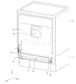
도 1 및 도 2는 본 발명의 일 실시예에 따른 식기 세척기를 나타내는 사시도들이다.
도 3은 도 1의 식기 세척기에서 도어의 외측 판넬이 제거된 상태를 나타내는 사시도이다.
도 4는 도 3의 A 부분을 나타내는 확대도이다.
도 5 및 도 6은 각각 세척조 바닥의 사시도 및 정면도이다.
도 7 및 도 8은 각각 실링부의 사시도 및 정면도이다.
도 9는 도 7의 실링부를 Ⅵ-Ⅵ'라인을 따라 절단한 단면도이다.
도 10은 다른 실시예에 따른 실링부를 나타내는 단면도이다.
도 11은 도 4의 Ⅰ-Ⅰ'라인을 따라 절단한 단면도이다.
도 12는 도 4의 Ⅱ-Ⅱ'라인을 따라 절단한 단면도이다.
도 13은 도 4의 Ⅲ-Ⅲ'라인을 따라 절단한 단면도이다.
도 14는 도 4의 Ⅳ-Ⅳ'라인을 따라 절단한 단면도이다.
도 15는 도 4의 Ⅴ-Ⅴ'라인을 따라 절단한 단면도이다.1 and 2 are perspective views showing a dishwasher according to an embodiment of the present invention.
3 is a perspective view showing a state in which the outer panel of the door is removed in the dish washer of FIG.
4 is an enlarged view showing part A of Fig.
5 and 6 are a perspective view and a front view, respectively, of the washing tub bottom.
7 and 8 are a perspective view and a front view of the sealing portion, respectively.
9 is a cross-sectional view of the sealing portion of FIG. 7 taken along line VI-VI '.
10 is a cross-sectional view showing a sealing portion according to another embodiment.
11 is a cross-sectional view taken along the line I-I 'of FIG.
12 is a cross-sectional view taken along line II-II 'of FIG.
13 is a cross-sectional view taken along line III-III 'of FIG.
14 is a cross-sectional view taken along line IV-IV 'of FIG.
15 is a cross-sectional view taken along line V-V 'of FIG.
이하, 본 발명의 일실시예에 대하여 상세하게 설명한다. 각 도면의 구성요소들에 참조부호를 부가함에 있어서, 동일한 구성요소들에 대해서는 비록 다른 도면상에 표시되더라도 가능한 한 동일한 부호를 가지도록 하고 있음에 유의해야 한다. 또한, 본 발명의 실시예를 설명함에 있어, 관련된 공지 구성 또는 기능에 대한 구체적인 설명이 본 발명의 실시예에 대한 이해를 방해한다고 판단되는 경우에는 그 상세한 설명은 생략한다. Hereinafter, one embodiment of the present invention will be described in detail. It should be noted that, in adding reference numerals to the constituent elements of the drawings, the same constituent elements are denoted by the same reference symbols as possible even if they are shown in different drawings. In the following description of the embodiments of the present invention, a detailed description of known functions and configurations incorporated herein will be omitted when it may make the difference that the embodiments of the present invention are not conclusive.
또한, 본 발명의 실시예의 구성 요소를 설명하는 데 있어서, 제 1, 제 2, A, B, (a), (b) 등의 용어를 사용할 수 있다. 이러한 용어는 그 구성 요소를 다른 구성 요소와 구별하기 위한 것일 뿐, 그 용어에 의해 해당 구성 요소의 본질이나 차례 또는 순서 등이 한정되지 않는다. 어떤 구성 요소가 다른 구성요소에 "연결", "결합" 또는 "접속"된다고 기재된 경우, 그 구성 요소는 그 다른 구성요소에 직접적으로 연결되거나 접속될 수 있지만, 각 구성 요소 사이에 또 다른 구성 요소가 "연결", "결합" 또는 "접속"될 수도 있다고 이해되어야 할 것이다. In describing the components of the embodiment of the present invention, terms such as first, second, A, B, (a), and (b) may be used. These terms are intended to distinguish the constituent elements from other constituent elements, and the terms do not limit the nature, order or order of the constituent elements. When a component is described as being "connected", "coupled", or "connected" to another component, the component may be directly connected or connected to the other component, Quot; may be "connected," "coupled," or "connected. &Quot;
이하, 첨부한 도면을 참고하여 본 발명의 식기 세척기에 대하여 상세히 설명한다. Hereinafter, the dish washer of the present invention will be described in detail with reference to the accompanying drawings.
도 1 및 도 2는 본 발명의 일 실시예에 따른 식기 세척기를 나타내는 사시도들이다. 이때, 도 1은 도어(3)가 닫힌 상태를 나타내고, 도 2는 도어(3)가 개방된 상태를 나타낸다. 도 3은 도 1의 식기 세척기에서 도어의 외측 판넬이 제거된 상태를 나타내는 사시도이다.1 and 2 are perspective views showing a dishwasher according to an embodiment of the present invention. At this time, Fig. 1 shows a state in which the
도 1 내지 도 3을 참조하면, 식기 세척기는 외관을 형성하는 하우징(1), 하우징(1) 내부에 구비되며 세척공간(21)을 형성하는 세척조(2), 세척공간(21)을 선택적으로 개폐하는 도어(3), 세척조(2)를 지지하는 베이스(4), 세척조(2) 내부에 구비되며 세척대상을 수용하는 랙(5), 세척수를 저장하는 섬프(도시되지 않음), 세척조(2) 내부에 구비되며 세척대상을 향하여 세척수를 분사하는 분사 암(6), 및 세척조(2)와 도어(3) 사이에 설치되어 세척수 유출을 방지하는 실링부(100)를 포함할 수 있다.1 to 3, the dishwasher includes a housing 1 forming an outer appearance, a
세척조(2)는 내부에 세척공간(21)을 형성하며, 일면이 개방된 형상을 가질 수 있다. 상기 개방된 일면은 도어(3)에 의해 선택적으로 개폐될 수 있다.The
이하에서는, 설명의 편의를 위하여 세척조(2)의 개방된 일면이 위치한 방향을 세척조(2)의 '전방'으로 정의하기로 한다. 즉, '전방'은 X축의 양의 방향을 의미하고, '후방'은 X축의 음의 방향을 의미한다. 또한 세척조(2)의 '측방'은 Y축 방향을 의미하고, '상방'은 Z축의 양의 방향을 의미하며, '하방'은 Z축의 음의 방향을 의미한다.Hereinafter, for the sake of convenience of description, the direction in which the opened one side of the
세척조(2)는 세척공간(21)의 바닥을 형성하는 세척조 바닥(23), 한 쌍의 측벽, 후벽, 및 천장을 포함할 수 있다. 세척조 바닥(23)에는 상기 섬프에 삽입되는 필터(7), 및 분사 암(6)이 결합될 수 있다. 또한, 세척조 바닥(23)에는 후술하는 실링부(100)가 장착될 수 있다.The
도어(3)는 하우징(1)에 회동 가능하게 연결되어 세척공간(21)을 선택적으로 개폐할 수 있다. 예를 들면, 도 2에 도시된 바와 같이, 도어(3)의 하부가 하우징(1)에 힌지 결합될 수 있다. 이 경우 도어(3)는 상기 하부를 중심으로 회전하여 세척조(2)를 개폐할 수 있다.The
한편, 도어(3)는 회동 가능해야 하므로 회전을 위한 여유 공간이 필요하다. 따라서, 세척조(2)와 도어(3) 사이는 완전히 밀폐되지 못할 수도 있다. 좀 더 구체적으로는, 세척조 바닥(23)과 도어(3) 사이에는 간극이 형성될 수 있고, 상기 간극을 통하여 세척수가 외부로 유출될 수 있다. 본 발명은 상기 간극에 실링부(100)를 설치함으로써 세척수 유출을 방지할 수 있다. 이에 대해서는 후술하기로 한다.On the other hand, since the
일 실시예에 있어서, 도어(3)는 세척공간(21) 측에 구비되는 내측 판넬(31), 및 내측 판넬(31)과 대향하며 도어(3)의 외관을 형성하는 외측 판넬(33)을 포함할 수 있다. 도어(3)를 닫으면(도 1 참조) 외측 판넬(33)이 외부로 노출되고, 도어(3)를 개방하면(도 2 참조) 내측 판넬(31)이 외부로 노출될 수 있다.The
내측 판넬(31)의 외측면에는 세제함(37)을 수용하기 위한 개구(32)가 형성되며, 내측면에는 실링부(100)가 결합될 수 있다. 이때, 내측 판넬(31)의 외측면은 세척공간(21)과 접하는 면을 의미하고, 내측 판넬(31)의 내측면은 상기 외측면의 반대면을 의미한다.An
외측 판넬(33)에는 식기 세척기를 제어하기 위한 콘트롤 판넬(8)이 구비될 수 있다. 콘트롤 판넬(8)은 식기 세척기의 전원을 온/오프하는 전원 스위치(81), 사용자가 식기 세척기 제어를 위한 명령을 입력하는 조작부(83), 식기 세척기의 동작 상태를 표시하는 디스플레이부(85) 등을 포함할 수 있다.The
베이스(4)는 하우징(1) 하부에 구비되며, 세척조(2)가 일정한 높이에 위치하도록 지지할 수 있다. 베이스(4) 내부에는 소정의 공간이 형성되는데, 상기 공간에는 상기 섬프, 및 스팀 발생 장치 등의 각종 기계 장치들이 수납될 수 있다. The
랙(5)은 세척대상을 수용하며, 세척조(2) 내부에 적어도 하나가 구비될 수 있다. 즉, 도 2에는 세척조(2) 상부에 설치되는 하나의 랙(5)만이 도시되어 있으나, 이는 설명의 편의를 위한 것으로 본 발명이 이에 제한되는 것은 아니다. 예를 들면, 식기 세척기는 상하로 이격된 2개 이상의 랙들을 포함할 수 있다.The
랙(5)은 세척조(2)의 상기 개방된 일면을 통해 세척조(2) 외부로 인출될 수 있다. 사용자는 랙(5)을 세척조(2) 외부로 인출함으로써, 세척대상을 수납하거나 또는 세척이 완료된 세척대상을 회수할 수 있다.The
상기 섬프는 외부로부터 물을 공급받아 저장하고, 상기 저장된 물을 식기 세척기 내에서 순환시킬 수 있다. 구체적으로, 상기 섬프에 저장된 물은 분사 암(6)을 통해 랙(5)에 수납된 세척대상으로 분사될 수 있다. 상기 분사된 물은 세척조 바닥(23)으로 낙하하고, 필터(7)를 거쳐 상기 섬프로 회수될 수 있다.The sump can receive and store water from the outside, and circulate the stored water in the dishwasher. Specifically, the water stored in the sump can be injected into the cleaning object accommodated in the
분사 암(6)은 세척조 바닥(23)에 회전 가능하게 장착되며, 랙(5)에 수납된 세척대상을 향하여 세척수를 분사할 수 있다. 이 때, 분사 암(6)은 회전하면서 세척수를 분사하므로, 정지한 상태로 세척수를 분사하는 경우에 비하여 세척수의 분사 범위를 증가시킬 수 있다. 이에 따라, 식기 세척기의 세척 효과가 증가할 수 있다.The spray arm 6 is rotatably mounted on the washing tub bottom 23 and is capable of spraying wash water toward a cleaning object accommodated in the
한편, 분사 암(6)에서 분사된 세척수는 랙(5)에 수용된 세척대상과 충돌한 후 세척조 바닥(23)으로 낙하하게 된다. 그런데, 세척수가 다양한 방향으로 분사되고 세척대상의 형상도 일정하지 않기 때문에, 낙하한 세척수는 다양한 방향의 흐름을 형성할 수 있다. 이 중에서, 필터(7)를 향해 흐르는 세척수는 상기 섬프로 곧바로 회수될 수 있고, 세척조(2)의 측벽이나 후벽을 향해 흐르는 세척수는 식기 세척기 외부로 유출될 염려가 거의 없다.On the other hand, the washing water sprayed from the spray arm 6 collides with the washing object accommodated in the
그러나, 도어(3)와 세척조 바닥(23) 사이는 완전히 밀폐되지 못하고 약간의 간극이 형성되기 때문에, 세척조(2)의 개방된 일면을 향하여 흐르는 세척수는 식기 세척기 외부로 유출될 수도 있다. 본 발명에서는 이와 같은 세척수의 외부 유출을 방지하기 위하여 도어(3)의 내측 판넬(31)과 세척조 바닥(23) 사이에 실링부(100)를 설치하였다. 이하에서는 실링부(100)에 대하여 보다 상세히 설명하기로 한다.However, since the gap between the
도 4는 도 3의 A 부분을 나타내는 확대도이다. 도 5 및 도 6은 각각 세척조 바닥의 사시도 및 정면도이다. 도 7 및 도 8은 각각 실링부의 사시도 및 정면도이다. 도 9는 도 7의 실링부를 Ⅵ-Ⅵ'라인을 따라 절단한 단면도이다. 도 10은 다른 실시예에 따른 실링부를 나타내는 단면도이다.4 is an enlarged view showing part A of Fig. 5 and 6 are a perspective view and a front view, respectively, of the washing tub bottom. 7 and 8 are a perspective view and a front view of the sealing portion, respectively. 9 is a cross-sectional view of the sealing portion of FIG. 7 taken along line VI-VI '. 10 is a cross-sectional view showing a sealing portion according to another embodiment.
먼저 도 5 및 도 6을 참조하면, 세척조 바닥(23)은 세척공간(21)의 바닥을 형성하는 바닥면(231), 및 바닥면(231)의 끝단으로부터 상방으로 절곡 형성된 차단벽(233), 한 쌍의 측벽(237) 및 후벽을 포함할 수 있다. 즉, 차단벽(233)은 세척조 바닥(23)의 전방 끝단에 형성된 벽면을 의미한다. 바닥면(231), 차단벽(233), 측벽(237) 및 상기 후벽에 의해 세척조 바닥(23)은 일정 량의 세척수를 수용할 수 있다. 세척조 바닥(23)에 수용된 세척수는 필터(7)를 거쳐 상기 섬프로 회수될 수 있다.5 and 6, the
그런데, 경우에 따라서는 세척수가 세척조 바닥(23)의 저장 용량을 초과할 수도 있다. 예를 들면, 필터(7)가 이물질로 막혀 상기 섬프로의 세척수 회수가 원활하지 않은 경우 또는 분사된 세척수의 양이 너무 많은 경우이다. 이 경우에는 세척수가 차단벽(233)을 넘어 식기 세척기 외부로 유출될 수 있다.However, in some cases, the washing water may exceed the storage capacity of the
이를 방지하기 위하여, 차단벽(233)에는 적어도 하나의 배출부(235)가 구비될 수 있다. 도 5 및 도 6에는 차단벽(233) 양 쪽에 서로 이격된 2개의 배출부(235)가 도시되어 있으나, 이에 제한되는 것은 아니다. 즉, 배출부(235)의 위치 및 개수는 필요에 따라 다양하게 변경될 수 있다.In order to prevent this, the blocking
배출부(235)는 차단벽(233)에 구비되며, 그 상면의 높이가 차단벽(233) 상면의 높이보다 더 낮을 수 있다. 이에 따라, 세척수는 세척조 바닥(23)의 저장 용량을 초과하기 이전에 배출부(235)로 배출될 수 있다.The
배출부(235)의 하부에는 물받이(13)가 설치될 수 있다. 물받이(13)는 하우징(1)의 일부인 하부 프레임(11)에 의해 지지될 수 있다. 물받이(13)는 배출부(235)를 통해 배출된 세척수를 베이스(4) 내부로 안내할 수 있다.The water receiving part (235) may be provided under the water receiving part (13). The
도 7 내지 도 9를 참조하면, 실링부(100)는 세척조 바닥(23)의 차단벽(233)에 결합하는 제1 결합부(110), 도어(3)에 결합하는 제2 결합부(120), 제1 결합부(110)와 제2 결합부(120)를 연결하는 몸체(130), 및 몸체(130)로부터 하방으로 연장하여 세척조 바닥(23)의 바닥면(231)에 접촉하는 실링 리브를 포함할 수 있다.7 to 9, the sealing
제1 결합부(110)는 차단벽(233)에 장착되어 실링부(100)를 세척조 바닥(23)에 고정할 수 있다. 이 때, 제1 결합부(110)의 내측면에는 복수개의 리브들이 형성될 수 있다. 상기 리브들은 제1 결합부(110)와 차단벽(233) 간의 결합력을 증가시킴으로써, 도어(3) 개폐 시 실링부(100)가 세척조 바닥(23)으로부터 이탈되는 것을 방지할 수 있다. 또한, 상기 리브들은 세척수가 차단벽(233)을 타고 넘어 외부로 유출되는 것을 방지할 수 있다.The
일 실시예에 있어서, 제1 결합부(110)는 차단벽(233)의 길이 방향을 따라 연장하되 배출부(235)를 덮지 않도록 구비될 수 있다. 이는 배출부(235)를 통한 세척수 배출을 방해하지 않기 위함이다.In one embodiment, the
예를 들어, 도 6에 도시된 바와 같이 한 쌍의 배출부(235)가 차단벽(233) 양쪽에 서로 이격 구비된 경우, 제1 결합부(110)는 상기 한 쌍의 배출부들(235) 사이에 형성될 수 있다. 즉, 제1 결합부(110)의 길이(L1, 도 8 참조)는 배출부들(235) 사이의 간극(D, 도 6 참조)보다 더 작을 수 있다.6, when the pair of
이와 다르게, 배출부(235)가 차단벽(233)의 중앙에 구비된 경우에는, 제1 결합부(110)는 가운데가 절단된 형상을 가질 수 있다.Alternatively, when the
제2 결합부(120)는 도어(3)에 결합되어 실링부(100)를 도어(3)에 고정할 수 있다. 예를 들면, 도 4에 도시된 바와 같이, 제2 결합부(120)는 도어(3)에 구비된 고정부(35)에 삽입될 수 있다. 이에 따라, 도어(3) 회동시에 제2 결합부(120)는 도어(3)와 함께 회동할 수 있다.The
일 실시예에 있어서, 제2 결합부(120)는 제1 결합부(110)보다 높은 위치에 구비될 수 있다.In one embodiment, the
세척조 바닥(23)은 고정되어 있으므로, 세척조 바닥(23)에 장착되는 제1 결합부(110)의 위치는 변하지 않을 수 있다. 반면, 도어(3)는 회전하여 세척공간(21)을 선택적으로 개폐하므로, 도어(3)에 결합된 제2 결합부(120)는 도어(3)와 함께 회동할 수 있다. 이 경우, 제2 결합부(120)가 제1 결합부보다 높은 위치에 위치함으로써 도어(3) 개방 시 몸체(130)의 변형을 최소화할 수 있다. 이에 따라, 도어(3)를 반복적으로 개폐하더라도 실링부(100)의 세척수 차단 효과를 유지할 수 있다.Since the washing tub bottom 23 is fixed, the position of the
몸체(130)는 제1 결합부(110)와 제2 결합부(120)를 연결하며, 도어(3)와 세척조 바닥(23) 사이의 공간을 통하여 세척수가 외부로 유출되는 것을 방지할 수 있다. 또한, 몸체(130)는 세척조(2) 내부의 소음을 차단함으로써 사용자의 만족감을 향상시킬 수 있다.The
몸체(130)는 세척조 바닥(23)의 양 측벽(237)까지 연장하여, 양 측벽(237)에 접촉할 수 있다. 이에 따라, 측벽(237)을 통한 세척수의 유출을 방지할 수 있다.The
한편, 도 11에 도시된 바와 같이, 차단벽(233)과 측벽(237)의 연결 부위는 소정의 곡률을 가지도록 라운드지게 구비될 수 있다. 이때, 몸체(130)의 가장자리 역시 소정의 곡률을 가지도록 라운드지게 형성됨으로써, 상기 차단벽(233)과 측벽(237)의 연결 부위에 밀착될 수 있다. 이에 따라, 세척수 차단 효과가 극대화될 수 있다.11, the connecting portion between the blocking
일 실시예에 있어서, 몸체(130)는 탄성을 가진 소재로 형성될 수 있다. 예를 들면, 상기 몸체는 고무, 실리콘 등으로 형성될 수 있다. 이에 따라, 도어(3)의 개폐 시 몸체(130)의 형상이 유연하게 변형될 수 있다.In one embodiment, the
몸체(130)의 하부에는 적어도 하나의 상기 실링 리브가 구비될 수 있다. 상기 실링 리브는 세척조 바닥(23)의 바닥면(231)에 접촉함으로써, 차단벽(233)을 향하여 흐르는 세척수를 차단할 수 있다. 즉, 몸체(130)는 바닥면(231)으로부터 이격되나, 상기 실링 리브가 바닥면(231)과 접촉함으로써 세척수 유출을 차단할 수 있다.At least one sealing rib may be provided under the
일 실시예에 있어서, 상기 실링 리브는 몸체(130)로부터 하방으로 연장하여 세척조 바닥(23)의 바닥면(231)과 접촉하는 다수개의 리브들을 포함할 수 있다.In an embodiment, the sealing rib may include a plurality of ribs extending downward from the
예를 들면, 도 9에 도시된 바와 같이, 상기 실링 리브는 차단벽(233)의 내측면에 접촉하는 제1 실링 리브(140), 및 제1 실링 리브(140)와 이격되어 구비되는 제2 실링 리브(150)를 포함할 수 있다.9, the sealing rib may include a
제1 실링 리브(140)는 차단벽(233)의 내측면을 따라 하방으로 연장하여 바닥면(231)에 접촉할 수 있다. 이에 따라, 제1 실링 리브(140)는 세척수가 차단벽(233)을 타고 넘는 것을 방지할 수 있다.The
제2 실링 리브(150)는 제1 실링 리브(140)와 이격된 위치로부터 하방으로 연장 형성되며, 적어도 하나가 구비될 수 있다. 이때, 제2 실링 리브(150)는 그 자체의 하중 및 몸체(130)의 하중에 의해 바닥면(231)에 밀착될 수 있다. 따라서, 세척수 차단 효과가 극대화될 수 있다.The
제2 실링 리브(150)는 세척조 바닥(23)의 양 측벽(237)을 향하여 연장하여, 양 측벽(237)에 각각 접촉할 수 있다. 이에 따라, 실링부(100)와 측벽(237) 사이의 공간을 통한 세척수 유출을 차단할 수 있다.The
한편, 차단벽(233)과 측벽(237)의 연결 부위는 소정의 곡률을 가지도록 라운드지게 구비될 수 있다. 따라서, 제2 실링 리브(150)의 가장자리 역시 소정의 곡률을 가지도록 라운드지게 형성됨으로써, 상기 차단벽(233)과 측벽(237)의 연결 부위에 밀착될 수 있다.The connecting portion between the blocking
일 실시예에 있어서, 제2 실링 리브(150)에는 적어도 하나의 슬릿(slit, 151)이 형성될 수 있다.In one embodiment, at least one
제2 실링 리브(150)는 차단벽(233)을 향하여 흐르는 세척수를 차단할 수 있다. 그러나, 세척조 바닥(23)에 많은 양의 세척수가 유입된 경우에는, 세척수가 제1 실링 리브(140)와 제2 실링 리브(150) 사이로 유입될 수도 있다. 슬릿(151)은 제1 및 제2 실링 리브(140, 150) 사이로 유입된 세척수를 후방으로 배출함으로써 실링부(100)와 바닥면(231) 사이에 세척수가 고이는 것을 방지할 수 있다.The
이 경우에 있어서, 제1 실링 리브(140)는 세척조 바닥(23)의 양 측벽(237)을 향하여 연장하되, 적어도 슬릿(151)을 커버할 수 있도록 구비된다. In this case, the
예를 들어, 도 8에 도시된 바와 같이, 제1 실링 리브(140)의 길이(L3)는 슬릿들(151) 간의 거리(L2)보다 더 클 수 있다. 이에 따라, 차단벽(233)을 향하여 흐르는 세척수가 슬릿(151)을 통과하더라도, 제1 실링 리브(140)가 이들을 차단하여 세척수 유출을 방지할 수 있다.For example, as shown in FIG. 8, the length L3 of the
다만, 제1 실링 리브(140)가 측벽(237)까지 연장되면 배출부(235)를 통한 세척수 배출이 어려울 수 있다. 따라서, 제1 실링 리브(140)는 양 측벽들(237) 사이의 간격보다는 더 짧게 형성되어야 할 것이다.However, if the
한편, 도어(3)가 반복적으로 개폐되면, 제2 실링 리브(150)의 바닥면(231)에 대한 밀착력이 약해질 수 있다. 이를 보완하기 위하여 상기 실링 리브는 몸체(130)와 제2 실링 리브(150)를 연결하는 보강 리브(160)를 더 포함할 수 있다.On the other hand, when the
보강 리브(160)는 제2 실링 리브(150)와 이격되어 몸체(130)로부터 하방으로 연장하되, 제2 실링 리브(150)의 연장 방향과 상이한 방향으로 연장할 수 있다. 이에 따라, 보강 리브(160)의 끝단은 제2 실링 리브(150)와 연결될 수 있다. 이 경우, 보강 리브(160)는 제2 실링 리브(150)를 하방으로 밀어줌으로써, 제2 실링 리브(150)와 바닥면(231) 사이의 밀착력을 향상시킬 수 있다.The reinforcing
일 실시예에 있어서, 도 10에 도시된 바와 같이, 보강 리브(161)는 제2 실링 리브(150)와 교차하여 바닥면(231)에 접촉할 수 있다. 이 경우, 보강 리브(161)는 제2 실링 리브(150)가 바닥면(231)에서 떨어지는 것을 방지하는 효과뿐만 아니라, 세척수를 차단하는 효과도 가질 수 있다.In one embodiment, as shown in FIG. 10, the reinforcing
일 실시예에 있어서, 상기 실링 리브는 내측 판넬(31)에 접촉하는 제3 실링 리브(170)를 더 포함할 수 있다. 제3 실링 리브(170)는 몸체(130)와 내측 판넬(31) 사이의 공간을 통해 세척수가 외부로 유출되는 것을 방지할 수 있다.In one embodiment, the sealing rib may further include a
이하에서는 도 11 내지 도 15를 참조로, 세척조 바닥(23)과 실링부(100) 사이의 결합관계에 대하여 보다 구체적으로 살펴보기로 한다.Hereinafter, with reference to FIGS. 11 to 15, the connection relationship between the bottom of the
도 11은 도 4의 Ⅰ-Ⅰ'라인을 따라 절단한 단면도이다. 도 12는 도 4의 Ⅱ-Ⅱ'라인을 따라 절단한 단면도이다. 도 13은 도 4의 Ⅲ-Ⅲ'라인을 따라 절단한 단면도이다. 도 14는 도 4의 Ⅳ-Ⅳ'라인을 따라 절단한 단면도이다. 도 15는 도 4의 Ⅴ-Ⅴ'라인을 따라 절단한 단면도이다. 11 is a cross-sectional view taken along the line I-I 'of FIG. 12 is a cross-sectional view taken along line II-II 'of FIG. 13 is a cross-sectional view taken along line III-III 'of FIG. 14 is a cross-sectional view taken along line IV-IV 'of FIG. 15 is a cross-sectional view taken along line V-V 'of FIG.
제1 결합부(110)는 차단벽(233)을 감싸도록 형성되며, 실링부(100)를 세척조 바닥(23)에 고정시킬 수 있다. 제1 결합부(110)의 내측면에는 복수개의 리브들이 형성되어 세척수가 차단벽(233)을 타고 넘는 것을 방지할 수 있다.The
한편, 제1 결합부(110)는 측벽(237)을 향하여 연장하되, 한 쌍의 배출부(235) 사이에 구비될 수 있다. 따라서, 제1 결합부(110)의 길이(L1, 도 8 참조)는 배출부들(235) 사이의 간극(D, 도 6 참조)보다 더 작을 수 있다.Meanwhile, the
배출부(235) 하부에는 물받이(13)가 구비되며, 배출부(235)를 통해 흘러 넘친 세척수를 베이스(4) 내부로 안내할 수 있다.A
제2 결합부(120)는 도어(3)의 내측 판넬(31)에 결합되며, 도어(3)와 함께 회동할 수 있다. 이때, 제2 결합부(120)는 제1 결합부(110)보다 높은 위치에 구비됨으로써, 도어(3) 개방 시 몸체(130)의 변형을 최소화할 수 있다.The
몸체(130)는 제1 결합부(110)와 제2 결합부(120)를 연결하며, 측벽(237)까지 연장될 수 있다. 이때, 몸체(130)는 아래로 볼록한 형성을 가지되 바닥면(231)으로부터 이격될 수 있다. 이에 따라, 도어(3) 개방 시 몸체(130)의 변형 량이 최소화될 수 있다.The
제1 실링 리브(140)는 차단벽(233)의 내측면을 따라 바닥면(231)까지 연장할 수 있다. 이때, 제1 실링 리브(140)와 차단벽(233) 사이에 복수개의 리브들이 더 형성될 수 있고, 세척수 차단 효과를 극대화시킬 수 있다.The
한편, 제1 실링 리브(140)는 측벽(237)을 향하여 연장하되, 적어도 슬릿(151)을 커버할 수 있도록 구비된다. 예를 들어, 도 8에 도시된 바와 같이, 제1 실링 리브(140)의 길이(L3)는 슬릿들(151) 사이의 간격(L2)보다 더 클 수 있다.Meanwhile, the
제2 실링 리브(150)는 몸체(130)로부터 하방으로 연장하여 바닥면(231)에 접촉하며, 측방으로는 측벽(237)까지 연장될 수 있다. 이에 따라, 제2 실링 리브(150)는 차단벽(233)을 향하여 흐르는 세척수를 차단할 수 있다. 또한, 제2 실링 리브(150)에는 슬릿(151)이 구비되어, 제1 및 제2 실링 리브(140, 150) 사이로 유입된 세척수를 후방으로 배출할 수 있다.The
보강 리브(160)는 제2 실링 리브(150)와 이격되어 몸체(130)로부터 하방으로 연장될 수 있다. 이때, 보강 리브(160)는 제2 실링 리브(150)의 연장 방향과 다른 방향으로 연장됨으로써, 보강 리브(160)의 끝단은 제2 실링 리브(150)와 연결될 수 있다. 보강 리브(160)는 제2 실링 리브(150)를 하방으로 밀어주어 제2 실링 리브(150)와 바닥면(231) 사이의 밀착력을 향상시킬 수 있다.The reinforcing
제3 실링 리브(170)는 몸체(130)로부터 내측 판넬(31)을 향하여 연장되며, 몸체(130)와 내측 판넬(31) 사이의 공간을 차폐할 수 있다.The
상술한 바와 같이, 세척조(2)의 개방된 일면, 즉 차단벽(233)을 향하여 흐르는 세척수는 제2 실링 리브(150)에 의해 1차적으로 차단되며, 제1 실링 리브(140)에 의해 2차적으로 차단될 수 있다. 또한, 제1 결합부(110) 내면에 형성된 리브들에 의해 3차적으로 차단될 수 있다. 또한, 제1 실링 리브(140)와 제2 실링 리브(150) 사이로 세척수가 유입되더라도, 제2 실링 리브(150)에 형성된 슬릿(151)을 통해 제거될 수 있다. 이에 따라, 실링부(100)는 상기 세척조(2)의 개방된 일면을 통한 세척수 유출을 효과적으로 방지할 수 있다.As described above, the washing water flowing toward the open side of the
1: 하우징
11: 하부 프레임
13: 물받이
2: 세척조
21: 세척공간
23: 세척조 바닥
231: 바닥면
233: 차단벽
235: 배출부
3: 도어
31: 내측 판넬
33: 외측 판넬
35: 결합부
4: 베이스
41: 전면 판넬
5: 랙
6: 분사 암
7: 필터
8: 콘트롤 판넬
100, 101: 실링부
110: 제1 결합부
120: 제2 결합부
130: 몸체
140: 제1 실링 리브
150: 제2 실링 리브
151: 슬릿
160, 161: 보강 리브
170: 제3 실링 리브1: housing 11: lower frame 13: water tray
2: washing tank 21: washing space 23: washing tub bottom
231: bottom surface 233: blocking wall 235:
3: Door 31: Inner panel 33: Outer panel
35: engaging portion 4: base 41: front panel
5: Rack 6: Discharge arm 7: Filter
8:
120: second coupling portion 130: body 140: first sealing rib
150: second sealing rib 151: slit 160, 161: reinforcing rib
170: third sealing rib
Claims (18)
상기 세척공간을 선택적으로 개폐하는 도어; 및
상기 세척조와 상기 도어 사이를 차폐하여 세척수가 외부로 유출되는 것을 방지하는 실링부를 포함하고,
상기 세척조는,
상기 세척공간의 바닥을 형성하는 바닥면; 및
상기 바닥면의 전방 끝단에서 상방으로 절곡 형성된 차단벽을 포함하고,
상기 실링부는,
상기 차단벽과 상기 도어 사이에 구비되며, 상기 바닥면과 이격되는 몸체;
상기 몸체로부터 상기 차단벽의 내측면을 따라 하방으로 연장하여 상기 바닥면에 밀착되는 제1 실링 리브; 및
상기 제1 실링 리브와 이격되어 구비되며, 상기 몸체로부터 하방으로 연장하여 상기 바닥면에 밀착되는 제2 실링 리브를 포함하는 것을 특징으로 하는 식기 세척기.A washing tub forming a washing space for washing dishes;
A door selectively opening and closing the washing space; And
And a sealing part for shielding between the washing tub and the door to prevent the washing water from flowing out to the outside,
The cleaning tank,
A bottom surface defining a bottom of the cleaning space; And
And a blocking wall bent upward at a front end of the bottom surface,
The sealing portion
A body provided between the blocking wall and the door and separated from the bottom surface;
A first sealing rib extending downward from the body along the inner surface of the blocking wall and closely contacting the bottom surface; And
And a second sealing rib that is spaced apart from the first sealing rib and extends downward from the body and closely contacts the bottom surface.
상기 몸체로부터 하방으로 연장하되, 일단은 상기 제2 실링 리브와 이격되도록 상기 몸체에 연결되며, 타단은 상기 제2 실링 리브에 연결되는 보강 리브를 더 포함하는 것을 특징으로 하는 식기 세척기.The sealing member according to claim 1,
Further comprising a reinforcing rib extending downward from the body, the reinforcing rib being connected to the body such that one end thereof is spaced apart from the second sealing rib, and the other end is connected to the second sealing rib.
상기 몸체로부터 하방으로 연장하되, 일단은 상기 제2 실링 리브와 이격되도록 상기 몸체에 연결되며, 타단은 하방으로 연장하여 상기 제2 실링 리브와 교차하는 보강 리브를 더 포함하는 것을 특징으로 하는 식기 세척기.The sealing member according to claim 1,
Further comprising a reinforcing rib extending downward from the body and connected to the body so that one end thereof is spaced apart from the second sealing rib and the other end extending downward to intersect the second sealing rib. .
상기 차단벽에 결합하는 제1 결합부; 및
상기 도어에 결합하는 제2 결합부를 더 포함하는 것을 특징으로 하는 식기 세척기.The sealing member according to claim 1,
A first engaging portion coupled to the blocking wall; And
Further comprising a second engaging portion coupled to the door.
상기 배출부는 상기 차단벽의 길이 방향을 따라 한 쌍이 형성되고,
상기 제1 결합부는 상기 한 쌍의 배출부 사이에서 연장되는 것을 특징으로 하는 식기 세척기.9. The method of claim 8,
Wherein the discharge portion is formed in a pair along a longitudinal direction of the blocking wall,
And the first engagement portion extends between the pair of discharge portions.
상기 도어는,
외관을 형성하는 외측 판넬; 및
상기 세척공간 측에 구비되는 내측 판넬을 포함하고,
상기 몸체는 상기 내측 판넬에 결합되는 것을 특징으로 하는 식기 세척기.The method according to claim 1,
The door
An outer panel forming an outer appearance; And
And an inner panel provided on the cleaning space side,
Wherein the body is coupled to the inner panel.
상기 세척조는 상기 바닥면의 양 측면을 커버하는 한 쌍의 측벽을 더 포함하고,
상기 차단벽과 상기 측벽의 연결 부위는 소정의 곡률을 갖도록 라운드지게 구비되며,
상기 몸체는 상기 연결 부위에 밀착되도록 가장자리가 라운드지게 형성되는 것을 특징으로 하는 식기 세척기.The method according to claim 1,
The cleaning tank further includes a pair of side walls covering both sides of the bottom surface,
Wherein the connection portion between the blocking wall and the side wall is rounded to have a predetermined curvature,
Wherein the body is rounded so as to be in close contact with the connection portion.
상기 세척공간을 선택적으로 개폐하는 도어;
상기 세척조 내부에 구비되어 상기 세척대상을 수용하는 랙;
상기 세척조 내부에 구비되어 세척수를 저장하는 섬프;
상기 세척조 내부에 구비되어 상기 세척대상을 향하여 세척수를 분사하는 분사 암; 및
상기 세척조와 상기 도어 사이로 세척수가 유출되는 것을 방지하기 위한 실링부를 포함하고,
상기 실링부는,
상기 세척조와 상기 도어를 연결하며, 아래로 볼록한 형상을 가지되 상기 세척조의 바닥면으로부터 이격되는 몸체; 및
상기 몸체로부터 하방으로 연장하여 상기 세척조의 바닥면에 접촉하는 실링 리브를 포함하는 것을 특징으로 하는 식기 세척기.A washing tub forming a washing space;
A door selectively opening and closing the washing space;
A rack provided in the washing tub to receive the object to be cleaned;
A sump provided in the washing tub to store wash water;
A spray arm provided in the washing tub and spraying washing water toward the washing target; And
And a sealing part for preventing the washing water from flowing out between the washing tub and the door,
The sealing portion
A body connecting the washing tub to the door, the body having a downward convex shape and spaced from a bottom surface of the washing tub; And
And a sealing rib extending downward from the body and contacting the bottom surface of the washing tub.
상기 세척조와 결합되는 제1 결합부; 및
상기 도어와 결합되며, 상기 제1 결합부보다 높은 위치에 구비되는 제2 결합부를 더 포함하는 것을 특징으로 하는 식기 세척기.16. The apparatus of claim 15,
A first coupling unit coupled to the washing tub; And
And a second coupling unit coupled to the door, the second coupling unit being located at a higher position than the first coupling unit.
상기 세척조의 내측면을 따라 상기 세척조의 바닥면까지 연장하는 제1 실링 리브;
상기 제1 실링 리브와 이격되어 구비되는 제2 실링 리브; 및
상기 제1 및 제2 실링 리브와 이격되며, 상기 제2 실링 리브의 연장 방향과 다른 방향으로 연장하여 상기 제2 실링 리브에 연결되는 보강 리브를 포함하는 것을 특징으로 하는 식기 세척기.16. The method of claim 15,
A first sealing rib extending along an inner surface of the washing tub to the bottom surface of the washing tub;
A second sealing rib spaced apart from the first sealing rib; And
And a reinforcing rib spaced apart from the first and second sealing ribs and extending in a direction different from the extending direction of the second sealing rib and connected to the second sealing rib.
Priority Applications (1)
| Application Number | Priority Date | Filing Date | Title |
|---|---|---|---|
| KR1020160073162A KR102491972B1 (en) | 2016-06-13 | 2016-06-13 | Dish Washer |
Applications Claiming Priority (1)
| Application Number | Priority Date | Filing Date | Title |
|---|---|---|---|
| KR1020160073162A KR102491972B1 (en) | 2016-06-13 | 2016-06-13 | Dish Washer |
Publications (2)
| Publication Number | Publication Date |
|---|---|
| KR20170140623A true KR20170140623A (en) | 2017-12-21 |
| KR102491972B1 KR102491972B1 (en) | 2023-01-26 |
Family
ID=60936082
Family Applications (1)
| Application Number | Title | Priority Date | Filing Date |
|---|---|---|---|
| KR1020160073162A Active KR102491972B1 (en) | 2016-06-13 | 2016-06-13 | Dish Washer |
Country Status (1)
| Country | Link |
|---|---|
| KR (1) | KR102491972B1 (en) |
Cited By (5)
| Publication number | Priority date | Publication date | Assignee | Title |
|---|---|---|---|---|
| CN111248830A (en) * | 2018-12-03 | 2020-06-09 | 浙江气派智能科技有限公司 | Door structure of a cleaning machine |
| KR20200095790A (en) * | 2019-02-01 | 2020-08-11 | 삼성전자주식회사 | Dishwasher |
| WO2021128676A1 (en) * | 2019-12-27 | 2021-07-01 | 深圳市金合联供应链技术有限公司 | Sealing mechanism for dishwasher |
| US20220183535A1 (en) * | 2019-08-29 | 2022-06-16 | Samsung Electronics Co., Ltd. | Dishwasher |
| CN117177699A (en) * | 2021-07-30 | 2023-12-05 | 三星电子株式会社 | Dishwasher |
Citations (4)
| Publication number | Priority date | Publication date | Assignee | Title |
|---|---|---|---|---|
| US20070181168A1 (en) * | 2003-12-22 | 2007-08-09 | Bsh Bosch Und Siemens Hausgerate, Gmbh | Dishwasher with a door seal |
| KR20080071352A (en) * | 2007-01-30 | 2008-08-04 | 삼성전자주식회사 | dish washer |
| EP2486839A2 (en) * | 2011-02-14 | 2012-08-15 | BSH Bosch und Siemens Hausgeräte GmbH | Dishwasher with a door seal |
| KR20160016250A (en) * | 2014-08-04 | 2016-02-15 | 삼성전자주식회사 | Sealing apparatus and dishwasher having the same |
-
2016
- 2016-06-13 KR KR1020160073162A patent/KR102491972B1/en active Active
Patent Citations (4)
| Publication number | Priority date | Publication date | Assignee | Title |
|---|---|---|---|---|
| US20070181168A1 (en) * | 2003-12-22 | 2007-08-09 | Bsh Bosch Und Siemens Hausgerate, Gmbh | Dishwasher with a door seal |
| KR20080071352A (en) * | 2007-01-30 | 2008-08-04 | 삼성전자주식회사 | dish washer |
| EP2486839A2 (en) * | 2011-02-14 | 2012-08-15 | BSH Bosch und Siemens Hausgeräte GmbH | Dishwasher with a door seal |
| KR20160016250A (en) * | 2014-08-04 | 2016-02-15 | 삼성전자주식회사 | Sealing apparatus and dishwasher having the same |
Cited By (6)
| Publication number | Priority date | Publication date | Assignee | Title |
|---|---|---|---|---|
| CN111248830A (en) * | 2018-12-03 | 2020-06-09 | 浙江气派智能科技有限公司 | Door structure of a cleaning machine |
| KR20200095790A (en) * | 2019-02-01 | 2020-08-11 | 삼성전자주식회사 | Dishwasher |
| US20220183535A1 (en) * | 2019-08-29 | 2022-06-16 | Samsung Electronics Co., Ltd. | Dishwasher |
| US12121196B2 (en) * | 2019-08-29 | 2024-10-22 | Samsung Electronics Co., Ltd. | Dishwasher |
| WO2021128676A1 (en) * | 2019-12-27 | 2021-07-01 | 深圳市金合联供应链技术有限公司 | Sealing mechanism for dishwasher |
| CN117177699A (en) * | 2021-07-30 | 2023-12-05 | 三星电子株式会社 | Dishwasher |
Also Published As
| Publication number | Publication date |
|---|---|
| KR102491972B1 (en) | 2023-01-26 |
Similar Documents
| Publication | Publication Date | Title |
|---|---|---|
| KR20180060506A (en) | Dish Washer | |
| KR20170140623A (en) | Dish Washer | |
| US6622896B2 (en) | Dishwasher detergent dispenser | |
| EP2387936B1 (en) | Dishwasher with detergent dispenser | |
| KR102822721B1 (en) | Dishwasher | |
| US12121196B2 (en) | Dishwasher | |
| RU2516488C2 (en) | Detergent cartridge container and dish washing machine with such container | |
| US9861257B2 (en) | Detergent dispenser module for a dishwashing appliance | |
| EP3293303B1 (en) | Laundry treating appliance with a slidable dispenser | |
| EP2425047B1 (en) | Front-loading household washing machine, in particular a laundry washing or washing/drying machine | |
| MX2007004668A (en) | Dispenser rinse system for a drawer-type dishwasher. | |
| US8733859B2 (en) | Silverware basket for a dishwasher appliance | |
| CN114206189A (en) | Household dish washer | |
| CN111093455A (en) | dishwasher | |
| US5211188A (en) | Dishwater additive dispensing apparatus | |
| CN111050624A (en) | Dish washing machine | |
| US11969131B2 (en) | Dishwasher | |
| US10646099B2 (en) | Dispensing device | |
| RU2423906C2 (en) | Dishwashing machine with improved device of supply at doors | |
| US20210251461A1 (en) | Dishwasher, method for operating a dishwasher, and computer program product | |
| KR20170096321A (en) | Apparatus for injecting liquid additive in washing machine | |
| TWI323165B (en) | ||
| US20100000585A1 (en) | Water-Conducting Household Appliance | |
| JP4609367B2 (en) | dishwasher | |
| KR20060010364A (en) | Automatic detergent dispenser structure of dishwasher |
Legal Events
| Date | Code | Title | Description |
|---|---|---|---|
| PA0109 | Patent application |
Patent event code: PA01091R01D Comment text: Patent Application Patent event date: 20160613 |
|
| PG1501 | Laying open of application | ||
| A201 | Request for examination | ||
| PA0201 | Request for examination |
Patent event code: PA02012R01D Patent event date: 20210531 Comment text: Request for Examination of Application Patent event code: PA02011R01I Patent event date: 20160613 Comment text: Patent Application |
|
| E902 | Notification of reason for refusal | ||
| PE0902 | Notice of grounds for rejection |
Comment text: Notification of reason for refusal Patent event date: 20221027 Patent event code: PE09021S01D |
|
| E701 | Decision to grant or registration of patent right | ||
| PE0701 | Decision of registration |
Patent event code: PE07011S01D Comment text: Decision to Grant Registration Patent event date: 20230109 |
|
| GRNT | Written decision to grant | ||
| PR0701 | Registration of establishment |
Comment text: Registration of Establishment Patent event date: 20230119 Patent event code: PR07011E01D |
|
| PR1002 | Payment of registration fee |
Payment date: 20230120 End annual number: 3 Start annual number: 1 |
|
| PG1601 | Publication of registration |