KR20170070333A - Display apparatus and method of driving the same - Google Patents
Display apparatus and method of driving the same Download PDFInfo
- Publication number
- KR20170070333A KR20170070333A KR1020150177132A KR20150177132A KR20170070333A KR 20170070333 A KR20170070333 A KR 20170070333A KR 1020150177132 A KR1020150177132 A KR 1020150177132A KR 20150177132 A KR20150177132 A KR 20150177132A KR 20170070333 A KR20170070333 A KR 20170070333A
- Authority
- KR
- South Korea
- Prior art keywords
- pixel
- frame
- polarity
- sub
- pixels
- Prior art date
- Legal status (The legal status is an assumption and is not a legal conclusion. Google has not performed a legal analysis and makes no representation as to the accuracy of the status listed.)
- Granted
Links
Images


Classifications
-
- G—PHYSICS
- G09—EDUCATION; CRYPTOGRAPHY; DISPLAY; ADVERTISING; SEALS
- G09G—ARRANGEMENTS OR CIRCUITS FOR CONTROL OF INDICATING DEVICES USING STATIC MEANS TO PRESENT VARIABLE INFORMATION
- G09G3/00—Control arrangements or circuits, of interest only in connection with visual indicators other than cathode-ray tubes
- G09G3/20—Control arrangements or circuits, of interest only in connection with visual indicators other than cathode-ray tubes for presentation of an assembly of a number of characters, e.g. a page, by composing the assembly by combination of individual elements arranged in a matrix no fixed position being assigned to or needed to be assigned to the individual characters or partial characters
- G09G3/34—Control arrangements or circuits, of interest only in connection with visual indicators other than cathode-ray tubes for presentation of an assembly of a number of characters, e.g. a page, by composing the assembly by combination of individual elements arranged in a matrix no fixed position being assigned to or needed to be assigned to the individual characters or partial characters by control of light from an independent source
- G09G3/36—Control arrangements or circuits, of interest only in connection with visual indicators other than cathode-ray tubes for presentation of an assembly of a number of characters, e.g. a page, by composing the assembly by combination of individual elements arranged in a matrix no fixed position being assigned to or needed to be assigned to the individual characters or partial characters by control of light from an independent source using liquid crystals
- G09G3/3611—Control of matrices with row and column drivers
- G09G3/3614—Control of polarity reversal in general
-
- G—PHYSICS
- G09—EDUCATION; CRYPTOGRAPHY; DISPLAY; ADVERTISING; SEALS
- G09G—ARRANGEMENTS OR CIRCUITS FOR CONTROL OF INDICATING DEVICES USING STATIC MEANS TO PRESENT VARIABLE INFORMATION
- G09G3/00—Control arrangements or circuits, of interest only in connection with visual indicators other than cathode-ray tubes
- G09G3/20—Control arrangements or circuits, of interest only in connection with visual indicators other than cathode-ray tubes for presentation of an assembly of a number of characters, e.g. a page, by composing the assembly by combination of individual elements arranged in a matrix no fixed position being assigned to or needed to be assigned to the individual characters or partial characters
- G09G3/34—Control arrangements or circuits, of interest only in connection with visual indicators other than cathode-ray tubes for presentation of an assembly of a number of characters, e.g. a page, by composing the assembly by combination of individual elements arranged in a matrix no fixed position being assigned to or needed to be assigned to the individual characters or partial characters by control of light from an independent source
- G09G3/36—Control arrangements or circuits, of interest only in connection with visual indicators other than cathode-ray tubes for presentation of an assembly of a number of characters, e.g. a page, by composing the assembly by combination of individual elements arranged in a matrix no fixed position being assigned to or needed to be assigned to the individual characters or partial characters by control of light from an independent source using liquid crystals
- G09G3/3611—Control of matrices with row and column drivers
- G09G3/3648—Control of matrices with row and column drivers using an active matrix
-
- G—PHYSICS
- G09—EDUCATION; CRYPTOGRAPHY; DISPLAY; ADVERTISING; SEALS
- G09G—ARRANGEMENTS OR CIRCUITS FOR CONTROL OF INDICATING DEVICES USING STATIC MEANS TO PRESENT VARIABLE INFORMATION
- G09G3/00—Control arrangements or circuits, of interest only in connection with visual indicators other than cathode-ray tubes
- G09G3/20—Control arrangements or circuits, of interest only in connection with visual indicators other than cathode-ray tubes for presentation of an assembly of a number of characters, e.g. a page, by composing the assembly by combination of individual elements arranged in a matrix no fixed position being assigned to or needed to be assigned to the individual characters or partial characters
- G09G3/34—Control arrangements or circuits, of interest only in connection with visual indicators other than cathode-ray tubes for presentation of an assembly of a number of characters, e.g. a page, by composing the assembly by combination of individual elements arranged in a matrix no fixed position being assigned to or needed to be assigned to the individual characters or partial characters by control of light from an independent source
- G09G3/36—Control arrangements or circuits, of interest only in connection with visual indicators other than cathode-ray tubes for presentation of an assembly of a number of characters, e.g. a page, by composing the assembly by combination of individual elements arranged in a matrix no fixed position being assigned to or needed to be assigned to the individual characters or partial characters by control of light from an independent source using liquid crystals
- G09G3/3611—Control of matrices with row and column drivers
- G09G3/3685—Details of drivers for data electrodes
- G09G3/3688—Details of drivers for data electrodes suitable for active matrices only
-
- G—PHYSICS
- G09—EDUCATION; CRYPTOGRAPHY; DISPLAY; ADVERTISING; SEALS
- G09G—ARRANGEMENTS OR CIRCUITS FOR CONTROL OF INDICATING DEVICES USING STATIC MEANS TO PRESENT VARIABLE INFORMATION
- G09G2300/00—Aspects of the constitution of display devices
- G09G2300/04—Structural and physical details of display devices
- G09G2300/0439—Pixel structures
- G09G2300/0452—Details of colour pixel setup, e.g. pixel composed of a red, a blue and two green components
-
- G—PHYSICS
- G09—EDUCATION; CRYPTOGRAPHY; DISPLAY; ADVERTISING; SEALS
- G09G—ARRANGEMENTS OR CIRCUITS FOR CONTROL OF INDICATING DEVICES USING STATIC MEANS TO PRESENT VARIABLE INFORMATION
- G09G2300/00—Aspects of the constitution of display devices
- G09G2300/08—Active matrix structure, i.e. with use of active elements, inclusive of non-linear two terminal elements, in the pixels together with light emitting or modulating elements
- G09G2300/0809—Several active elements per pixel in active matrix panels
- G09G2300/0819—Several active elements per pixel in active matrix panels used for counteracting undesired variations, e.g. feedback or autozeroing
Landscapes
- Engineering & Computer Science (AREA)
- Chemical & Material Sciences (AREA)
- Crystallography & Structural Chemistry (AREA)
- Physics & Mathematics (AREA)
- Computer Hardware Design (AREA)
- General Physics & Mathematics (AREA)
- Theoretical Computer Science (AREA)
- Control Of Indicators Other Than Cathode Ray Tubes (AREA)
- Liquid Crystal Display Device Control (AREA)
- Liquid Crystal (AREA)
Abstract
표시 장치는 복수의 데이터 라인들, 상기 데이터 라인들과 교차하는 복수의 게이트 라인들 및 상기 데이터 라인들에 연결된 복수의 화소들을 포함하고, 각 화소는 복수의 컬러 서브 화소들을 포함하는 표시 패널, 및 기w준 전압 대비 정 극성 및 부 극성의 데이터 전압들을 출력하는 데이터 구동부를 포함하고, 상기 복수의 컬러 서브 화소들 중 적어도 하나의 컬러 서브 화소의 극성 스턱 주기는 다른 컬러 서브 화소의 극성 스턱 주기와 다르며, 상기 극성 스턱 주기는 동일 극성이 프레임 당 이동하는 화소 거리인 것을 특징으로 한다. 이에 따르면, 복수의 컬러 서브 화소들 중 적어도 하나의 컬러 서브 화소의 프레임 단위의 극성 스턱 주기는 다른 컬러 서브 화소의 프레임 단위의 극성 스턱 주기와 다르게 함으로써 동영상의 이동 속도와 상기 컬러 서브 화소들의 극성 스턱 주기와의 일치 조건을 최소화하여 무빙 줄 얼룩을 개선할 수 있다. The display device includes a display panel including a plurality of data lines, a plurality of gate lines crossing the data lines, and a plurality of pixels connected to the data lines, wherein each pixel includes a plurality of color sub-pixels, Wherein the polarity stuck period of at least one of the plurality of color sub-pixels is different from the polarity stuck period of the other color sub-pixels, And the polarity stuck period is characterized in that the same polarity is a pixel distance moving per frame. According to this, the polarity stuck period of the frame unit of at least one color sub-pixel among the plurality of color sub-pixels is different from the polarity stuck period of the frame units of the other color sub-pixels, It is possible to minimize moving line irregularity by minimizing the matching condition with the period.

Description
본 발명은 표시 장치 및 표시 장치의 구동 방법에 관한 것으로, 보다 상세하게는 표시 품질을 개선하기 위한 표시 장치 및 표시 장치의 구동 방법에 관한 것이다. The present invention relates to a display device and a driving method of the display device, and more particularly to a display device for improving display quality and a driving method of the display device.
일반적으로, 액정 표시 장치는 화소 전극을 포함하는 제1 기판, 공통 전극을 포함하는 제2 기판 및 상기 기판들 사이에 개재되는 액정층을 포함한다. 상기 두 전극에 전압을 인가하여 액정층에 전계를 생성하고, 이 전계의 세기를 조절하여 액정층을 통과하는 빛의 투과율을 조절함으로써 원하는 화상을 얻는다. Generally, a liquid crystal display device includes a first substrate including a pixel electrode, a second substrate including a common electrode, and a liquid crystal layer interposed between the substrates. A voltage is applied to the two electrodes to generate an electric field in the liquid crystal layer, and the intensity of the electric field is adjusted to adjust the transmittance of light passing through the liquid crystal layer to obtain a desired image.
일반적으로, 표시 장치는 표시 패널 및 패널 구동부를 포함한다. 상기 표시 패널은 복수의 게이트 라인들, 복수의 데이터 라인들 및 상기 게이트 라인들 및 상기 데이터 라인들에 연결되는 복수의 화소들을 포함한다. 각 화소는 복수의 서브화소들을 포함한다. 상기 패널 구동부는 상기 복수의 게이트 라인들에 게이트 신호를 제공하는 게이트 구동부 및 상기 데이터 라인들에 데이터 전압을 제공하는 데이터 구동부를 포함한다. Generally, the display apparatus includes a display panel and a panel driver. The display panel includes a plurality of gate lines, a plurality of data lines, and a plurality of pixels connected to the gate lines and the data lines. Each pixel includes a plurality of sub-pixels. The panel driver includes a gate driver for providing a gate signal to the plurality of gate lines, and a data driver for providing a data voltage to the data lines.
상기 서브 화소들은 공통 전압에 대해서 정 극성 또는 부 극성의 데이터 전압이 인가되고, 상기 데이터 전압은 프레임 단위로 반전한다. The data voltages of the positive or negative polarity are applied to the sub-pixels with respect to the common voltage, and the data voltages are inverted frame by frame.
상기 표시 패널에 동영상을 표시하는 경우 움직이는 물체를 관찰자의 눈이 따라감으로써 상기 서브 화소들의 극성 배치에 의해 세로줄 또는 가로줄 등과 같은 형태의 무빙 줄 얼룩이 시인된다. When a moving picture is displayed on the display panel, a moving object is moved along the eyes of the observer, and moving line unevenness such as a vertical line or a horizontal line is visually recognized by the polar arrangement of the sub-pixels.
이에 본 발명의 기술적 과제는 이러한 점에서 착안된 것으로, 본 발명의 목적은 무빙 줄 얼룩을 개선하기 위한 표시 장치를 제공하는 것이다. SUMMARY OF THE INVENTION Accordingly, the present invention has been made keeping in mind the above problems occurring in the prior art, and it is an object of the present invention to provide a display device for improving moving line unevenness.
본 발명의 다른 목적은 상기 표시 장치의 구동 방법을 제공하는 것이다. Another object of the present invention is to provide a method of driving the display device.
상기한 본 발명의 목적을 실현하기 위한 일 실시예에 따른 표시 장치는 복수의 데이터 라인들, 상기 데이터 라인들과 교차하는 복수의 게이트 라인들 및 상기 데이터 라인들에 연결된 복수의 화소들을 포함하고, 각 화소는 복수의 컬러 서브 화소들을 포함하는 표시 패널, 및 기준 전압 대비 정 극성 및 부 극성의 데이터 전압들을 출력하는 데이터 구동부를 포함하고, 상기 복수의 컬러 서브 화소들 중 적어도 하나의 컬러 서브 화소의 극성 스턱 주기는 다른 컬러 서브 화소의 극성 스턱 주기와 다르며, 동일 극성이 프레임 당 이동하는 화소 거리인 것을 특징으로 한다. According to an aspect of the present invention, a display device includes a plurality of data lines, a plurality of gate lines crossing the data lines, and a plurality of pixels connected to the data lines, Each pixel includes a display panel including a plurality of color sub-pixels, and a data driver for outputting data voltages of positive and negative polarity with respect to a reference voltage, wherein at least one of the plurality of color sub- The polarity stuck period is different from the polarity streak period of the other color sub-pixels, and the same polarity is a pixel distance moving per frame.
일 실시예에서, 상기 복수의 컬러 서브 화소들 중 적어도 하나의 컬러 서브 화소의 극성 스턱 주기는 프레임 단위로 불규칙적으로 변할 수 있다. In one embodiment, the polarity stuck period of at least one color sub-pixel among the plurality of color sub-pixels may vary irregularly on a frame-by-frame basis.
일 실시예에서, 상기 적어도 하나의 컬러 서브 화소의 극성 스턱 주기는 프레임 단위로 불규칙적으로 변하고, 상기 불규칙적인 변화는 주기성을 가질 수 있다. In one embodiment, the polarity stuck period of the at least one color sub-pixel varies irregularly on a frame-by-frame basis, and the irregular change may have periodicity.
일 실시예에서, 상기 복수의 컬러 서브 화소들 중 적어도 하나의 컬러 서브 화소의 프레임 단위의 극성 스턱 주기는 1PPF 이하일 수 있다. In one embodiment, the polarity stuck period of a frame unit of at least one color sub-pixel among the plurality of color sub-pixels may be 1 PPF or less.
일 실시예에서, 상기 표시 패널은 복수의 화소 행들과 복수의 화소 열들을 포함하고, 화소 열의 컬러 서브 화소들은 인접한 데이터 라인들에 교대로 연결될 수 있다. In one embodiment, the display panel includes a plurality of pixel rows and a plurality of pixel columns, and the color sub-pixels of the pixel column may be alternately connected to adjacent data lines.
일 실시예에서, 상기 복수의 컬러 서브 화소들은 레드 서브 화소, 그린 서브 화소, 블루 서브 화소 및 화이트 서브 화소를 포함할 수 있다. In one embodiment, the plurality of color sub-pixels may include a red sub-pixel, a green sub-pixel, a blue sub-pixel, and a white sub-pixel.
일 실시예에서, 상기 데이터 구동부는 제N 프레임에 제1 반전 패턴("+-+--+-+")에 대응하는 극성의 데이터 전압을 상기 데이터 라인에 출력하고, 제N+1 프레임에 상기 제1 반전 패턴에 반전된 극성의 데이터 전압을 상기 데이터 라인에 출력하고, 제N+2 프레임에 제2 반전 패턴("++++----")에 대응하는 극성의 데이터 전압을 상기 데이터 라인에 출력하고, 제N+3 프레임에 상기 제2 반전 패턴에 반전된 극성의 데이터 전압을 상기 데이터 라인에 출력할 수 있다. In one embodiment, the data driver outputs a data voltage of a polarity corresponding to a first inverted pattern ("+ - + - + - +") to the data line in the Nth frame, And outputs a polarity data voltage corresponding to the second inverted pattern ("++++ - -") to the (N + 2) And outputs the data voltage of the polarity inverted to the second inverted pattern to the data line in the (N + 3) -th frame.
일 실시예에서, 상기 데이터 구동부는 제N 프레임에 제1 반전 패턴("+-+--+-+")에 대응하는 극성의 데이터 전압을 상기 데이터 라인에 출력하고, 제N+1 프레임에 제2 반전 패턴("++++----")에 대응하는 극성의 데이터 전압을 상기 데이터 라인에 출력하고, 제N+2 프레임에 상기 제1 반전 패턴에 반전된 극성의 데이터 전압을 상기 데이터 라인에 출력하고, 제N+3 프레임에 상기 제2 반전 패턴에 반전된 극성의 데이터 전압을 상기 데이터 라인에 출력할 수 있다. In one embodiment, the data driver outputs a data voltage of a polarity corresponding to a first inverted pattern ("+ - + - + - +") to the data line in the Nth frame, And outputs a data voltage of a polarity corresponding to the second inverted pattern ("++++ ----") to the data line and outputs a data voltage of polarity inverted to the first inverted pattern in the And outputs the data voltage of the polarity inverted to the second inverted pattern to the data line in the (N + 3) -th frame.
상기한 본 발명의 목적을 실현하기 위한 일 실시예에 따른 복수의 데이터 라인들, 상기 데이터 라인들과 교차하는 복수의 게이트 라인들 및 상기 데이터 라인들에 연결된 복수의 화소들을 포함하고, 각 화소는 복수의 컬러 서브 화소들을 포함하는 표시 장치의 구동 방법에서, 기준 전압 대비 정 극성 및 부 극성의 데이터 전압들을 출력하고, 상기 복수의 컬러 서브 화소들 중 적어도 하나의 컬러 서브 화소의 극성 스턱 주기는 다른 컬러 서브 화소의 극성 스턱 주기와 다르며 상기 극성 스턱 주기는 동일 극성이 프레임 당 이동하는 화소 거리인 것을 특징으로 한다. A plurality of data lines, a plurality of gate lines intersecting the data lines, and a plurality of pixels connected to the data lines according to an embodiment for realizing the above-described present invention, A method of driving a display device including a plurality of color sub-pixels, the method comprising: outputting data voltages of positive and negative polarity with respect to a reference voltage, wherein a polarity stuck period of at least one of the plurality of color sub- The polarity stuck period of the color sub-pixel is different from the polarity stuck period of the color sub-pixel, and the polarity stuck period is a pixel distance in which the same polarity moves per frame.
일 실시예에서, 상기 복수의 컬러 서브 화소들 중 적어도 하나의 컬러 서브 화소의 극성 스턱 주기는 프레임 단위로 불규칙적으로 변할 수 있다. In one embodiment, the polarity stuck period of at least one color sub-pixel among the plurality of color sub-pixels may vary irregularly on a frame-by-frame basis.
일 실시예에서, 상기 적어도 하나의 컬러 서브 화소의 극성 스턱 주기는 프레임 단위로 불규칙적으로 변하고, 상기 불규칙적인 변화는 주기성을 가질 수 있다.In one embodiment, the polarity stuck period of the at least one color sub-pixel varies irregularly on a frame-by-frame basis, and the irregular change may have periodicity.
일 실시예에서, 상기 복수의 컬러 서브 화소들 중 적어도 하나의 컬러 서브 화소의 프레임 단위의 극성 스턱 주기는 1PPF 이하일 수 있다. In one embodiment, the polarity stuck period of a frame unit of at least one color sub-pixel among the plurality of color sub-pixels may be 1 PPF or less.
일 실시예에서, 상기 표시 패널은 복수의 화소 행들과 복수의 화소 열들을 포함하고, 화소 열의 컬러 서브 화소들은 인접한 데이터 라인들에 교대로 연결될 수 있다. In one embodiment, the display panel includes a plurality of pixel rows and a plurality of pixel columns, and the color sub-pixels of the pixel column may be alternately connected to adjacent data lines.
일 실시예에서, 상기 복수의 컬러 서브 화소들은 레드 서브 화소, 그린 서브 화소, 블루 서브 화소 및 화이트 서브 화소를 포함할 수 있다. In one embodiment, the plurality of color sub-pixels may include a red sub-pixel, a green sub-pixel, a blue sub-pixel, and a white sub-pixel.
일 실시예에서, 제N 프레임에 제1 반전 패턴("+-+--+-+")에 대응하는 극성의 데이터 전압을 데이터 라인에 출력하고, 제N+1 프레임에 상기 제1 반전 패턴에 반전된 극성의 데이터 전압을 데이터 라인에 출력하고, 제N+2 프레임에 제2 반전 패턴("++++----")에 대응하는 극성의 데이터 전압을 데이터 라인에 출력하고, 제N+3 프레임에 상기 제2 반전 패턴에 반전된 극성의 데이터 전압을 데이터 라인에 출력할 수 있다. In one embodiment, a data voltage having a polarity corresponding to a first inverted pattern ("+ - + - + - +") is output to the data line in the Nth frame, And outputs a polarity data voltage corresponding to the second inverted pattern ("++++ ----") to the data line in the (N + 2) And the data voltage of the polarity reversed to the second inverted pattern can be output to the data line in the (N + 3) -th frame.
일 실시예에서, 제N 프레임에 제1 반전 패턴("+-+--+-+")에 대응하는 극성의 데이터 전압을 상기 데이터 라인에 출력하고, 제N+1 프레임에 제2 반전 패턴("++++----")에 대응하는 극성의 데이터 전압을 상기 데이터 라인에 출력하고, 제N+2 프레임에 상기 제1 반전 패턴에 반전된 극성의 데이터 전압을 상기 데이터 라인에 출력하고, 제N+3 프레임에 상기 제2 반전 패턴에 반전된 극성의 데이터 전압을 상기 데이터 라인에 출력할 수 있다. In one embodiment, a data voltage of a polarity corresponding to a first inverted pattern ("+ - + - + - +") is output to the data line in the Nth frame, ("++++ ----") to the data line, and outputs a data voltage of polarity inverted to the first inverted pattern to the data line in the (N + 2) And outputs the data voltage of the polarity inverted to the second inverted pattern to the data line in the (N + 3) -th frame.
이와 같은 실시예에 따르면, 복수의 컬러 서브 화소들 중 적어도 하나의 컬러 서브 화소의 프레임 단위의 극성 스턱 주기는 다른 컬러 서브 화소의 프레임 단위의 극성 스턱 주기와 다르게 함으로써 동영상의 이동 속도와 상기 컬러 서브 화소들의 극성 스턱 주기와의 일치 조건을 최소화하여 무빙 줄 얼룩을 개선할 수 있다. According to this embodiment, the polarity stuck period of the frame unit of at least one color sub-pixel among the plurality of color sub-pixels is different from the polarity stuck cycle of the frame unit of the other color sub-pixels, It is possible to minimize the coincidence condition with the polarity stuck period of the pixels to improve moving line unevenness.
도 1은 본 발명의 일 실시예에 따른 표시 장치의 블록도이다.
도 2a 및 도 2b는 본 발명의 실시예에 따른 출력 극성 패턴 및 출력 극성 주기를 나타낸 개념도이다.
도 3은 도 2a 및 도 2b의 출력 극성 패턴 및 출력 극성 주기에 따른 레드 서브 화소의 극성 스턱 주기를 설명하기 위한 개념도이다.
도 4는 도 2a 및 도 2b의 출력 극성 패턴 및 출력 극성 주기에 따른 그린 서브 화소의 극성 스턱 주기를 설명하기 위한 개념도이다.
도 5는 도 2a 및 도 2b의 출력 극성 패턴 및 출력 극성 주기에 따른 블루 서브 화소의 극성 스턱 주기를 설명하기 위한 개념도이다.
도 6은 도 2a 및 도 2b의 출력 극성 패턴 및 출력 극성 주기에 따른 화이트 서브 화소의 극성 스턱 주기를 설명하기 위한 개념도이다.
도 7a 및 도 7b는 본 발명의 실시예에 따른 출력 극성 패턴 및 출력 극성 주기를 나타낸 개념도이다.
도 8은 도 7a 및 도 7b의 출력 극성 패턴 및 출력 극성 주기에 따른 레드 서브 화소의 극성 스턱 주기를 설명하기 위한 개념도이다.
도 9는 도 7a 및 도 7b의 출력 극성 패턴 및 출력 극성 주기에 따른 그린 서브 화소의 극성 스턱 주기를 설명하기 위한 개념도이다.
도 10은 도 7a 및 도 7b의 출력 극성 패턴 및 출력 극성 주기에 따른 블루 서브 화소의 극성 스턱 주기를 설명하기 위한 개념도이다.
도 11은 도 7a 및 도 7b의 출력 극성 패턴 및 출력 극성 주기에 따른 화이트 서브 화소의 극성 스턱 주기를 설명하기 위한 개념도이다.1 is a block diagram of a display device according to an embodiment of the present invention.
2A and 2B are conceptual diagrams illustrating an output polarity pattern and an output polarity period according to an embodiment of the present invention.
3 is a conceptual diagram for explaining a polarity stuck period of a red sub-pixel according to an output polarity pattern and an output polarity period of FIGS. 2A and 2B.
4 is a conceptual diagram for explaining a polarity stuck period of a green sub-pixel according to an output polarity pattern and an output polarity period of FIGS. 2A and 2B.
5 is a conceptual diagram for explaining the polarity stuck period of the blue sub-pixel according to the output polarity pattern and the output polarity period of FIGS. 2A and 2B.
6 is a conceptual diagram for explaining a polarity stuck period of a white sub-pixel according to the output polarity pattern and the output polarity period of FIGS. 2A and 2B.
7A and 7B are conceptual diagrams illustrating an output polarity pattern and an output polarity period according to an embodiment of the present invention.
8 is a conceptual diagram for explaining the polarity stuck period of the red sub-pixel according to the output polarity pattern and the output polarity period of FIGS. 7A and 7B.
9 is a conceptual diagram for explaining the polarity stuck period of the green sub-pixel according to the output polarity pattern and the output polarity period of FIGS. 7A and 7B.
10 is a conceptual diagram for explaining the polarity stuck period of the blue sub-pixel according to the output polarity pattern and the output polarity period of FIGS. 7A and 7B.
11 is a conceptual diagram for explaining the polarity stuck period of the white sub-pixel according to the output polarity pattern and the output polarity period of FIGS. 7A and 7B.
이하, 도면들을 참조하여 본 발명의 바람직한 실시예들을 보다 상세하게 설명하기로 한다.Hereinafter, preferred embodiments of the present invention will be described in more detail with reference to the drawings.
도 1은 본 발명의 일 실시예에 따른 표시 장치의 블록도이다. 1 is a block diagram of a display device according to an embodiment of the present invention.
도 1을 참조하면, 상기 표시 장치는 표시 패널(100), 타이밍 제어부(200), 게이트 구동부(300) 및 데이터 구동부(400)를 포함한다. Referring to FIG. 1, the display device includes a
상기 표시 패널(100)은 복수의 게이트 라인들(GLn, GLn+1, GLn+2, GLn+3), 복수의 데이터 라인들(DLm, DLm+1, DLm+2, DLm+3, DLm+4, DLm+5, DLm+6, DLm+7) 및 복수의 화소들(P)을 포함한다(n 및 m 은 자연수).The
상기 게이트 라인들(GLn, GLn+1, GLn+2, GLn+3)은 제1 방향(D1)으로 연장되고 상기 제1 방향(D1)과 교차하는 제2 방향(D2)으로 배열된다. The gate lines GLn, GLn + 1, GLn + 2 and GLn + 3 extend in the first direction D1 and are arranged in the second direction D2 intersecting the first direction D1.
상기 데이터 라인들(DLm, DLm+1, DLm+2, DLm+3, DLm+4, DLm+5, DLm+6, DLm+7)은 상기 제2 방향(D2)으로 연장되고 상기 제1 방향(D1)으로 배열된다. The data lines DLm, DLm + 1, DLm + 2, DLm + 3, DLm + 4, DLm + 5, DLm + 6, DLm + 7 extend in the second direction D2, (D1).
상기 화소들(P)은 복수의 화소 행들과 복수의 화소 열들을 포함하는 매트릭스 형태로 배열된다. 화소 행(PR)은 상기 제1 방향(D1)으로 배열된 복수의 화소들을 포함하고 화소 열(PC)은 상기 제2 방향(D2)으로 배열된 복수의 화소들을 포함한다. 상기 화소들(P) 각각은 복수의 컬러 서브 화소들을 포함한다. The pixels P are arranged in a matrix form including a plurality of pixel rows and a plurality of pixel columns. The pixel row PR includes a plurality of pixels arranged in the first direction D1 and the pixel column PC includes a plurality of pixels arranged in the second direction D2. Each of the pixels P includes a plurality of color sub-pixels.
예를 들면, 도 1에 도시된 바와 같이, 화소(P)는 4개의 제1 컬러 서브 화소, 제2 컬러 서브 화소, 제3 컬러 서브 화소 및 제4 컬러 서브 화소로 이루어질 수 있다. 또는 3개의 제1 컬러 서브 화소, 제2 컬러 서브 화소 및 제3 컬러 서브 화소로 이루어질 수 있다. 상기 4개 컬러들은 레드, 그린, 블루 및 화이트일 수 있고, 3개의 컬러들은 레드, 그린 및 블루일 수 있다. 이하에서는 제1 컬러는 레드(R, red), 제2 컬러는 그린(G, Green), 제3 컬러는 블루(B, Blue) 및 제4 컬러는 화이트(W, White)를 대신하여 설명한다. For example, as shown in FIG. 1, the pixel P may be composed of four first color sub-pixels, a second color sub-pixel, a third color sub-pixel, and a fourth color sub-pixel. Or three first color sub-pixels, a second color sub-pixel, and a third color sub-pixel. The four colors may be red, green, blue and white, and the three colors may be red, green and blue. In the following description, the first color is replaced by red (R, red), the second color is replaced by green (G, Green), the third color is replaced by blue (B and Blue), and the fourth color is replaced by white (W, White) .
상기 화소 행(PR)은 제1 화소(P)와 제2 화소(Pa)가 교대로 배치될 수 있다. In the pixel row PR, the first pixel P and the second pixel Pa may be alternately arranged.
상기 제1 화소(P)는 상좌측에 레드 서브 화소(R)가 배치되고, 상우측에 그린 서브 화소(G)가 배치되고, 하좌측에 블루 서브 화소(B)가 배치되고, 하우측에 제4 화이트 서브 화소(W)가 배치된다. 상기 제2 화소(Pa)는 상좌측에 블루 서브 화소(B)가 배치되고, 상우측에 화이트 서브 화소(W)가 배치되고, 하좌측에 레드 서브 화소(R)가 배치되고, 하우측에 그린 서브 화소(G)가 배치된다. 한편, 상기 제1 화소(P)에 대응하는 화소 열(PC)은 상기 제1 화소(P)만을 포함하고, 상기 제2 화소(Pa)에 대응하는 화소 열은 제2 화소(Pa)만을 포함한다. The first pixel P includes a red sub pixel R disposed on the upper left side, a green sub pixel G arranged on the upper right side, a blue sub pixel B arranged on the lower left side, The fourth white sub-pixel W is arranged. In the second pixel Pa, the blue sub-pixel B is arranged on the upper left side, the white sub-pixel W is arranged on the upper right side, the red sub-pixel R is arranged on the lower left side, Green sub-pixels G are arranged. The pixel column PC corresponding to the first pixel P includes only the first pixel P and the pixel column corresponding to the second pixel Pa includes only the second pixel Pa do.
물론, 도시되지 않았으나, 상기 화소 행은 제1 화소만을 포함할 수 있다. Of course, although not shown, the pixel row may include only the first pixel.
또한, 같은 서브 화소 열에 포함된 컬러 서브 화소들은 인접한 데이터 라인들에 엇갈려 연결된 엇갈림 구조를 가질 수 있고, 또는 같은 서브 화소 열에 포함된 컬러 서브 화소들은 인접한 데이터 라인들 중 하나에 모두 연결된 비엇갈림 구조를 가질 수 있다.In addition, the color sub-pixels included in the same sub-pixel column may have a staggered structure staggered to adjacent data lines, or the color sub-pixels included in the same sub-pixel column may have a non-staggered structure connected to one of adjacent data lines Lt; / RTI >
도 1은 엇갈림 구조를 도시한 것으로, 제m 데이터 라인(DLm)과 제m+1 데이터 라인(DLm+1) 사이에 위치한 같은 서브 화소 열의 컬러 서브 화소들은 상기 제m 데이터 라인(DLm)과 상기 제m+1 데이터 라인(DLm+1)에 교대로 연결된다. FIG. 1 illustrates a staggered structure in which color sub-pixels in the same sub-pixel column located between the m-th data line DLm and the (m + 1) th data line DLm + And are alternately connected to the (m + 1) th data
상기 타이밍 제어부(200)는 외부 장치로부터 입력 영상 데이터(DIN) 및 입력 제어 신호(CONT)를 수신한다. 상기 타이밍 제어부(200)는 상기 입력 영상 데이터(DIN)를 상기 표시 패널(100)에 대응하는 출력 영상 데이터(DOUT)로 변환하여 상기 데이터 구동부(400)에 제공한다. 예를 들면, 상기 입력 영상 데이터(DIN)는 레드, 그린 및 블루 데이터를 포함하고, 상기 출력 영상 데이터(DOUT)는 상기 표시 패널(100)의 화소 구조에 따라서 레드, 그린, 블루 및 화이트 데이터를 포함할 수 있다. 상기 타이밍 제어부(200)는 상기 입력 동기 신호(CONT)를 이용하여 상기 게이트 구동부(300)를 제어하는 게이트 제어 신호(GCS)를 생성하고, 상기 데이터 구동부(400)를 제어하는 데이터 제어 신호(DCS)를 생성한다. 상기 입력 제어 신호는 입력 수직 동기 신호, 입력 수평 동기 신호, 입력 데이터 인에이블 신호, 입력 클럭 신호 등을 포함할 수 있다. 상기 게이트 제어 신호(GCS)는 수직 개시 신호, 게이트 클럭 신호, 게이트 인에이블 신호 등을 포함할 수 있다. 상기 데이터 제어 신호(DCS)는 수평 동기 신호, 픽셀 클럭 신호, 로드 신호, 반전 제어 신호 등을 포함할 수 있다. The
본 실시예에 따르면, 상기 데이터 제어 신호(DCS)는 상기 데이터 구동부(400)로부터 출력되는 복수의 데이터 전압들의 극성을 기준 전압 대비 정 극성(+) 또는 부 극성(-)으로 각각 제어하기 위한 출력 극성 제어 신호를 포함할 수 있다. According to the present embodiment, the data control signal DCS includes an output for controlling the polarity of a plurality of data voltages output from the
상기 출력 극성 제어 신호는 동일 극성이 프레임 당 이동하는 화소 거리인 극성 스턱(stuck) 주기를 제어한다. 상기 극성 스턱 주기의 단위는 PPF(Pixel per Frame)로 정의될 수 있다. The output polarity control signal controls a polarity stuck period in which the same polarity is a pixel distance moving per frame. The unit of the polarity stuck period may be defined as a pixel per frame (PPF).
예를 들면, 상기 출력 극성 제어 신호는 설정된 출력 극성 패턴 및 출력 극성 주기에 기초하며, 상기 화소의 복수의 컬러 서브 화소들의 극성 스턱 주기를 프레임 단위로 불규칙적으로 변하도록 상기 데이터 구동부(400)를 제어한다. For example, the output polarity control signal is based on a set output polarity pattern and an output polarity period, and controls the
일반적인 화소의 극성 스턱 주기와 동영상의 이동 속도(프레임 당 영상의 화소 이동 거리: PPF)가 일치할 경우 관찰자의 눈에는 무빙 줄 얼룩이 강하게 시인된다. 이러한 점에서, 본 실시예에 따르면, 상기 화소의 극성 스턱 주기를 프레임 단위로 불규칙으로 변하시킴으로써 상기 극성 스턱 주기와 동영상의 이동 속도의 일치 조건을 최소화하여 무빙 줄 얼룩이 시인을 줄일 수 있다. Moving line stain is visibly observed in the observer's eyes when the polarity stuck period of a typical pixel and the moving speed of the moving image (moving distance of the pixel per frame: PPF) coincide with each other. In this respect, according to the present embodiment, the polarity stuck period of the pixel is irregularly changed in units of frames, thereby minimizing the matching condition between the polarity stuck period and the moving speed of the moving picture, thereby reducing moving line unevenness.
상기 게이트 구동부(300)는 상기 게이트 제어 신호(GCS)에 기초하여 게이트 신호를 생성하고, 스캔 방향을 따라서 상기 게이트 신호를 상기 게이트 라인들(GLn, GLn+1, GLn+2, GLn+3)에 순차적으로 출력한다. The
상기 데이터 구동부(400)는 감마 전압을 이용하여 상기 출력 영상 데이터(DOUT)를 데이터 전압으로 변환하고, 상기 데이터 제어 신호(DCS)에 기초하여 상기 데이터 전압의 극성을 기준 전압 대비 정 극성(+) 또는 부 극성(-)으로 제어하여 상기 데이터 라인들(DLm, DLm+1, DLm+2, DLm+3, DLm+4, DLm+5, DLm+6, DLm+7)에 출력한다. The
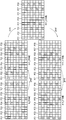
도 2a 및 도 2b는 본 발명의 실시예에 따른 출력 극성 패턴 및 출력 극성 주기를 나타낸 개념도이다. 도 3은 도 2a 및 도 2b의 출력 극성 패턴 및 출력 극성 주기에 따른 제2 서브 화소의 제2 극성 스턱 주기를 설명하기 위한 개념도이다. 2A and 2B are conceptual diagrams illustrating an output polarity pattern and an output polarity period according to an embodiment of the present invention. FIG. 3 is a conceptual diagram for explaining a second polarity stuck period of the second sub-pixel according to the output polarity pattern and the output polarity period of FIGS. 2A and 2B.
도 2a는 출력 극성 제어 신호에 대응하는 출력 극성 패턴 및 출력 극성 주기의 일예이다. 상기 출력 극성 패턴 및 출력 극성 주기는 다양하게 설정될 수 있고, 상기 타이밍 제어부의 레지스터에 저장될 수 있다. 상기 타이밍 제어부는 설정된 상기 출력 극성 패턴 및 출력 극성 주기에 기초한 상기 출력 극성 제어 신호를 상기 데이터 구동부에 제공한다. 2A is an example of an output polarity pattern and an output polarity period corresponding to an output polarity control signal. The output polarity pattern and the output polarity period may be variously set and stored in a register of the timing control unit. The timing control unit provides the output polarity control signal based on the output polarity pattern and the output polarity period to the data driver.
본 실시예에 따르면, 상기 출력 극성 패턴은, 2 프레임은 제1 반전 패턴("+-+--+-+")을 갖고 연속하는 2 프레임은 제2 반전 패턴("++++----")을 가지며, 출력 극성 주기는 4 프레임 주기를 갖는다.According to the present embodiment, the output polarity pattern has a first inverted pattern ("+ - + - + - +") for two frames and a second inverted pattern ("++++ - - "), and the output polarity period has four frame periods.
제N 프레임(N_FRAME)은 제m 내지 제m+7 데이터 라인들(DLm, DLm+1, DLm+2, DLm+3, DLm+4, DLm+5, DLm+6, DLm+7)에 "+-+--+-+"의 극성 순서로 데이터 전압을 출력하고, 제N+1 프레임(N+1_FRAME)은 상기 제m 내지 제m+7 데이터 라인들(DLm, DLm+1, DLm+2, DLm+3, DLm+4, DLm+5, DLm+6, DLm+7)에 제1 반전 패턴("+-+--+-+")과 반전된 "-+-++-+-"의 극성 순서로 데이터 전압을 출력한다. The Nth frame N_FRAME is added to the (m + 7) th data lines DLm, DLm + 1, DLm + 2, DLm + 3, DLm + 4, DLm + 5, DLm + 6, DLm + Th data lines DLm, DLm + 1, DLm + 1, and N + 1_FRAME output the data voltages in the order of + - + - + - + - + - +) and inverted by a first inverted pattern ("+ - + - + - +") to the data lines DLm + 2, DLm + 3, DLm + 4, DLm + 5, DLm + 6, DLm + - "in the order of polarity.
엇갈림 구조에 따라서 도 2b를 참조하면, 제N 프레임(N_FRAME)의 표시 패널은 홀수 번째 컬러 화소 행(SPR_O)은 "+-+--+-+"의 극성이 반복되고, 짝수 번째 컬러 화소 행(SPR_E)은 홀수 번째 컬러 화소 행(SPR_O)의 극성에 대해서 1 서브 화소만큼 쉬프트된 "-+--+-++"의 극성이 반복된다. 제N+1 프레임(N+1_FRAME)의 표시 패널은 홀수 번째 컬러 화소 행(SPR_O)은 "-+-++-+-"의 극성이 반복되고, 짝수 번째 컬러 화소 행(SPR_E)은 홀수 번째 컬러 화소 행(SPR_O)의 극성에 대해서 1 서브 화소만큼 쉬프트된 "+-++-+--"의 극성이 반복된다.Referring to FIG. 2B, in the display panel of the N-th frame N_FRAME, the polarity of "+ - + - + - +" is repeated in odd-numbered color pixel rows SPR_O, (SPR_E) is repeated with the polarity of "- + - + - ++" shifted by one sub-pixel with respect to the polarity of the odd-numbered color pixel row (SPR_O). The polarity of "- + - ++ - + -" is repeated in odd-numbered color pixel rows (SPR_O) and odd-numbered color pixel rows (SPR_E) are repeated in the display panel of the (N + 1) The polarity of " + - ++ - + - "shifted by one sub-pixel is repeated with respect to the polarity of the color pixel row SPR_O.
제N+2 프레임((N+2__FRAME)은 제m 내지 제m+7 데이터 라인들(DLm, DLm+1, DLm+2, DLm+3, DLm+4, DLm+5, DLm+6, DLm+7)에 제2 반전 패턴("++++----")의 극성 순서로 데이터 전압을 출력하고, 제N+3 프레임(N+3_FRAME)은 상기 제m 내지 제m+7 데이터 라인들(DLm, DLm+1, DLm+2, DLm+3, DLm+4, DLm+5, DLm+6, DLm+7)에 제2 반전 패턴("++++----")과 반전된 "----++++"의 극성 순서로 데이터 전압을 출력한다. DLm + 1, DLm + 2, DLm + 3, DLm + 4, DLm + 5, DLm + 6, DLm + + 7) in the order of the polarity of the second inverted pattern ("++++ ----"), and the (N + 3_FRAME) ("++++ ----") to the lines DLm, DLm + 1, DLm + 2, DLm + 3, DLm + 4, DLm + 5, DLm + 6, DLm + And the inverted "---- ++++" polarity order.
엇갈림 구조에 따라서 도 2b를 참조하면, 제N+2 프레임(N+2_FRAME)의 표시 패널은 홀수 번째 컬러 화소 행(SPR_O)은 "++++----"의 극성이 반복되고, 짝수 번째 컬러 화소 행(SPR_E)은 홀수 번째 컬러 화소 행(SPR_O)의 극성에 대해서 1 서브 화소만큼 쉬프트된 "+++----+"의 극성이 반복된다. 제N+3 프레임(N+3_FRAME)의 표시 패널은 홀수 번째 컬러 화소 행(SPR_O)은 "----++++"의 극성이 반복되고, 짝수 번째 컬러 화소 행(SPR_E)은 홀수 번째 컬러 화소 행(SPR_O)의 극성에 대해서 1 서브 화소만큼 쉬프트된 "---++++-"의 극성이 반복된다.Referring to FIG. 2B according to the staggered structure, the odd-numbered color pixel row SPR_O of the display panel of the (N + 2_FRAME) th frame repeats the polarity of "++++ ----" Th color pixel row SPR_E has a polarity of " +++ ---- + "shifted by one sub-pixel with respect to the polarity of the odd-numbered color pixel row SPR_O. In the display panel of the (N + 3) -th frame (N + 3) frame, the polarity of "---- ++++" is repeated in the odd-numbered color pixel row SPR_O and the odd- The polarity of " --- ++++ - "shifted by one sub-pixel is repeated for the polarity of the color pixel row SPR_O.
도 3은 도 2a 및 도 2b의 출력 극성 패턴 및 출력 극성 주기에 따른 레드 서브 화소의 극성 스턱 주기를 설명하기 위한 개념도이다. 3 is a conceptual diagram for explaining a polarity stuck period of a red sub-pixel according to an output polarity pattern and an output polarity period of FIGS. 2A and 2B.
도 3을 참조하면, 제N 프레임(N_FRAME)에서는 제1 화소 열(PC1)의 레드 서브 화소는 정 극성(+)을 갖고, 제2 화소 열(PC2)의 레드 서브 화소는 부 극성(-)을 갖고, 제3 화소 열(PC3)의 레드 서브 화소는 부 극성(-)을 갖고, 제4 화소 열(PC4)의 레드 서브 화소는 정 극성(+)을 갖고, 제5 화소 열(PC5)의 레드 서브 화소는 정 극성(+)을 갖고, 제6 화소 열(PC6)의 레드 서브 화소는 부 극성(-)을 갖고, 제7 화소 열(PC7)의 레드 서브 화소는 부 극성(-)을 갖고, 제8 화소 열(PC8)의 레드 서브 화소는 정 극성(+)을 갖는다.3, in the N-th frame N_FRAME, the red sub-pixel of the first pixel column PC1 has a positive polarity and the red sub-pixel of the second pixel column PC2 has a negative polarity. The red sub-pixel of the third pixel column PC3 has a negative polarity and the red sub-pixel of the fourth pixel column PC4 has a positive polarity, The red sub-pixel of the seventh pixel line PC7 has negative polarity and the red sub-pixel of the sixth pixel line PC6 has negative polarity. , And the red sub-pixel of the eighth pixel column PC8 has the positive polarity (+).
다음, 제N+1 프레임(N+1_FRAME)은 제3 내지 제8 화소의 극성들이 제N 프레임(N_FRAME)의 제1 내지 제6 화소의 극성들과 각각 일치한다. 즉, 제N 프레임(N_FRAME)에서 제1 화소 열(PC1)의 레드 서브 화소와 제N+1 프레임(N+1_FRAME)에서 제3 화소 열(PC3)의 레드 서브 화소의 극성(+)이 일치하고, 제N 프레임(N_FRAME)에서 제2 화소 열(PC2)의 레드 서브 화소와 제N+1 프레임(N+1_FRAME)에서 제4 화소 열(PC4)의 레드 서브 화소의 극성(-)이 일치하고, 제N 프레임(N_FRAME)에서 제3 화소 열(PC3)의 레드 서브 화소와 제N+1 프레임(N+1_FRAME)에서 제5 화소 열(PC5)의 레드 서브 화소의 극성(-)이 일치하고, 제N 프레임(N_FRAME)에서 제4 화소 열(PC4)의 레드 서브 화소와 제N+1 프레임(N+1_FRAME)에서 제6 화소 열(PC6)의 레드 서브 화소의 극성(+)이 일치하고, 제N 프레임(N_FRAME)에서 제5 화소 열(PC5)의 레드 서브 화소와 제N+1 프레임(N+1_FRAME)에서 제7 화소 열(PC7)의 레드 서브 화소의 극성(+)이 일치하고, 제N 프레임(N_FRAME)에서 제6 화소 열(PC6)의 레드 서브 화소와 제N+1 프레임(N+1_FRAME)에서 제8 화소 열(PC8)의 레드 서브 화소의 극성(-)이 일치한다. 따라서 상기 제N 및 제N+1 프레임들(N_FRAME, N+1_FRAME) 간의 극성 스턱 주기는 2PPF(Pixel Per Frame)이다. Next, the polarities of the third to eighth pixels in the (N + 1) - frame N + 1 frame N + 1_FRAME coincide with the polarities of the first to sixth pixels of the Nth frame N_FRAME, respectively. That is, the polarity (+) of the red sub-pixel of the third pixel column PC3 in the N + 1 frame N + 1_FRAME coincides with the red sub-pixel of the first pixel column PC1 in the Nth frame N_FRAME (-) of the red sub-pixel of the fourth pixel train PC4 in the Nth frame N_FRAME to the red sub-pixel of the second pixel train PC2 and the N + 1th frame N + 1_FRAME coincide with each other (-) of the red sub-pixel of the fifth pixel column PC5 to the red sub-pixel of the third pixel column PC3 in the Nth frame N_FRAME coincides with the polarity (-) of the red sub-pixel of the fifth pixel column PC5 in the (N + 1) And the polarities (+) of the red sub-pixels of the fourth pixel train PC4 in the Nth frame N_FRAME match the polarities of the red sub-pixels of the sixth pixel train PC6 in the (N + 1) (+) Of the red sub-pixel of the seventh pixel row PC7 in the Nth frame N_FRAME to the red sub-pixel of the fifth pixel row PC5 and the N + 1th frame N + 1_FRAME coincide with each other In the Nth frame N_FRAME to the red of the sixth pixel row PC6, The polarities (-) of the red sub-pixels of the eighth pixel row PC8 coincide with those of the (N + 1) th frame and the (N + 1) Therefore, the polarity stuck period between the Nth and (N + 1) -th frames N_FRAME and N + 1_FRAME is 2PPF (Pixel Per Frame).
같은 방식으로, 제N+2 프레임(N+2_FRAME)은 제4 내지 제8 화소의 극성들이 제N+1 프레임(N+1_FRAME)의 제1 내지 제5 화소의 극성들과 각각 일치한다. 따라서 상기 제N+1 및 제N+2 프레임들(N+1_FRAME, N+2_FRAME) 간의 극성 스턱 주기는 3PPF이다. In the same manner, the polarities of the fourth to eighth pixels in the (N + 2_FRAME) th frame of the (N + 2_FRAME) coincide with the polarities of the first to fifth pixels of the (N + 1) Therefore, the polarity stuck period between the (N + 1) th and (N + 2) -th frames N + 1_FRAME and N + 2_FRAME is 3PPF.
제N+3 프레임(N+3_FRAME)은 제3 내지 제8 화소의 극성들이 제N+2 프레임(N+2_FRAME)의 제1 내지 제6 화소의 극성들과 각각 일치한다. 따라서 상기 제N+2 및 제N+3 프레임들(N+2_FRAME, N+3_FRAME) 간의 극성 스턱 주기는 2PPF이다. The (N + 3) frame N + 3 frame N + 3_FRAME coincides with the polarities of the first to sixth pixels of the (N + 2) -frame N + 2 frame, respectively. Therefore, the polarity stuck period between the (N + 2) and the (N + 3) -th frame N + 2_FRAME, N + 3_FRAME is 2PPF.
제N+4 프레임(N+4_FRAME)은 제2 내지 제8 화소의 극성들이 제N+3 프레임(N+3_FRAME)의 제1 내지 제7 화소의 극성들과 각각 일치한다. 따라서 상기 제N+3 및 제N+4 프레임들(N+3_FRAME, N+4_FRAME) 간의 극성 스턱 주기는 1PPF이다. The polarities of the second to eighth pixels in the (N + 4) -frame N + 4 frame coincide with the polarities of the first to seventh pixels of the (N + 3) - frame N + 3 respectively. Accordingly, the polarity stuck period between the (N + 3) th frame and the (N + 4) -th frame N + 4_FRAME is 1 PPF.
이상에서와 같이, 레드 서브 화소의 극성 스턱 주기는 2PPF/3PPF/2PPF/1PPF를 반복하는 프레임 단위로 불규칙적인 주기를 갖는다. As described above, the polarity stamper period of the red sub-pixel has an irregular period in units of frames for repeating 2PPF / 3PPF / 2PPF / 1PPF.
도 4는 도 2a 및 도 2b의 출력 극성 패턴 및 출력 극성 주기에 따른 그린 서브 화소의 극성 스턱 주기를 설명하기 위한 개념도이다.4 is a conceptual diagram for explaining a polarity stuck period of a green sub-pixel according to an output polarity pattern and an output polarity period of FIGS. 2A and 2B.
도 4를 참조하면, 제N 프레임(N_FRAME)에서는 제1 화소 열(PC1)의 그린 서브 화소는 부 극성(-)을 갖고, 제2 화소 열(PC2)의 그린 서브 화소는 부 극성(-)을 갖고, 제3 화소 열(PC3)의 그린 서브 화소는 정 극성(+)을 갖고, 제4 화소 열(PC4)의 그린 서브 화소는 정 극성(+)을 갖고, 제5 화소 열(PC5)의 그린 서브 화소는 부 극성(-)을 갖고, 제6 화소 열(PC6)의 그린 서브 화소는 부 극성(-)을 갖고, 제7 화소 열(PC7)의 그린 서브 화소는 정 극성(+)을 갖고, 제8 화소 열(PC8)의 그린 서브 화소는 정 극성(+)을 갖는다.Referring to FIG. 4, in the N-th frame N_FRAME, the green sub-pixel of the first pixel column PC1 has a negative polarity and the green sub-pixel of the second pixel column PC2 has a negative polarity. , The green sub-pixel of the third pixel column PC3 has the positive polarity, the green sub-pixel of the fourth pixel column PC4 has the positive polarity and the fifth pixel column PC5 has the positive The green sub-pixel of the sixth pixel column PC6 has negative polarity and the green sub-pixel of the seventh pixel column PC7 has the negative polarity negative. And the green sub-pixel of the eighth pixel column PC8 has the positive polarity (+).
다음, 제N+1 프레임(N+1_FRAME)은 제3 내지 제8 화소의 극성들이 제N 프레임(N_FRAME)의 제1 내지 제6 화소의 극성들과 각각 일치한다. 즉, 제N 프레임(N_FRAME)에서 제1 화소 열(PC1)의 그린 서브 화소와 제N+1 프레임(N+1_FRAME)에서 제3 화소 열(PC3)의 그린 서브 화소의 극성(-)이 일치하고, 제N 프레임(N_FRAME)에서 제2 화소 열(PC2)의 그린 서브 화소와 제N+1 프레임(N+1_FRAME)에서 제4 화소 열(PC4)의 그린 서브 화소의 극성(-)이 일치하고, 제N 프레임(N_FRAME)에서 제3 화소 열(PC3)의 그린 서브 화소와 제N+1 프레임(N+1_FRAME)에서 제5 화소 열(PC5)의 그린 서브 화소의 극성(+)이 일치하고, 제N 프레임(N_FRAME)에서 제4 화소 열(PC4)의 그린 서브 화소와 제N+1 프레임(N+1_FRAME)에서 제6 화소 열(PC6)의 그린 서브 화소의 극성(+)이 일치하고, 제N 프레임(N_FRAME)에서 제5 화소 열(PC5)의 그린 서브 화소와 제N+1 프레임(N+1_FRAME)에서 제7 화소 열(PC7)의 그린 서브 화소의 극성(-)이 일치하고, 제N 프레임(N_FRAME)에서 제6 화소 열(PC6)의 그린 서브 화소와 제N+1 프레임(N+1_FRAME)에서 제8 화소 열(PC8)의 그린 서브 화소의 극성(-)이 일치한다. 따라서 상기 제N 및 제N+1 프레임들(N_FRAME, N+1_FRAME) 간의 극성 스턱 주기는 2PPF(Pixel Per Frame)이다. Next, the polarities of the third to eighth pixels in the (N + 1) - frame N + 1 frame N + 1_FRAME coincide with the polarities of the first to sixth pixels of the Nth frame N_FRAME, respectively. That is, the polarity (-) of the green sub-pixel of the first pixel train PC1 in the Nth frame N_FRAME matches the green sub-pixel of the third pixel train PC3 in the (N + 1) And the polarity (-) of the green sub-pixel of the second pixel train PC2 in the Nth frame N_FRAME and the green sub-pixel of the fourth pixel train PC4 in the (N + 1) th frame N + 1_FRAME coincide with each other (+) Of the green sub-pixel of the third pixel train PC3 in the Nth frame N_FRAME and the green sub-pixel of the fifth pixel train PC5 in the (N + 1) th frame N + 1_FRAME coincide with each other And the polarity (+) of the green sub-pixel of the fourth pixel train PC4 in the Nth frame N_FRAME coincides with the green sub-pixel of the sixth pixel train PC6 in the (N + 1) And the polarity (-) of the green sub-pixel of the fifth pixel column PC5 in the Nth frame N_FRAME coincides with the green sub-pixel of the seventh pixel column PC7 in the (N + 1) , And the green of the sixth pixel row PC6 in the Nth frame N_FRAME (-) of the green sub-pixel of the eighth pixel row PC8 in the (N + 1) th frame and the (N + 1) th frame are coincident with each other. Therefore, the polarity stuck period between the Nth and (N + 1) -th frames N_FRAME and N + 1_FRAME is 2PPF (Pixel Per Frame).
같은 방식으로, 제N+2 프레임(N+2_FRAME)은 제4 내지 제8 화소의 극성들이 제N+1 프레임(N+1_FRAME)의 제1 내지 제5 화소의 극성들과 각각 일치한다. 따라서 상기 제N+1 및 제N+2 프레임들(N+1_FRAME, N+2_FRAME) 간의 극성 스턱 주기는 3PPF이다. In the same manner, the polarities of the fourth to eighth pixels in the (N + 2_FRAME) th frame of the (N + 2_FRAME) coincide with the polarities of the first to fifth pixels of the (N + 1) Therefore, the polarity stuck period between the (N + 1) th and (N + 2) -th frames N + 1_FRAME and N + 2_FRAME is 3PPF.
제N+3 프레임(N+3_FRAME)은 제3 내지 제8 화소의 극성들이 제N+2 프레임(N+2_FRAME)의 제1 내지 제6 화소의 극성들과 각각 일치한다. 따라서 상기 제N+2 및 제N+3 프레임들(N+2_FRAME, N+3_FRAME) 간의 극성 스턱 주기는 2PPF이다. The (N + 3) frame N + 3 frame N + 3_FRAME coincides with the polarities of the first to sixth pixels of the (N + 2) -frame N + 2 frame, respectively. Therefore, the polarity stuck period between the (N + 2) and the (N + 3) -th frame N + 2_FRAME, N + 3_FRAME is 2PPF.
제N+4 프레임(N+4_FRAME)은 제2 내지 제8 화소의 극성들이 제N+3 프레임(N+3_FRAME)의 제1 내지 제7 화소의 극성들과 각각 일치한다. 따라서 상기 제N+3 및 제N+4 프레임들(N+3_FRAME, N+4_FRAME) 간의 극성 스턱 주기는 1PPF이다. The polarities of the second to eighth pixels in the (N + 4) -frame N + 4 frame coincide with the polarities of the first to seventh pixels of the (N + 3) - frame N + 3 respectively. Accordingly, the polarity stuck period between the (N + 3) th frame and the (N + 4) -th frame N + 4_FRAME is 1 PPF.
이상에서와 같이, 그린 서브 화소의 극성 스턱 주기는 2PPF/3PPF/2PPF/1PPF를 반복하는 프레임 단위로 불규칙적인 주기를 갖는다. As described above, the polarity stap period of the green sub-pixel has an irregular period in units of frames for repeating 2PPF / 3PPF / 2PPF / 1PPF.
도 5는 도 2a 및 도 2b의 출력 극성 패턴 및 출력 극성 주기에 따른 블루 서브 화소의 극성 스턱 주기를 설명하기 위한 개념도이다.5 is a conceptual diagram for explaining the polarity stuck period of the blue sub-pixel according to the output polarity pattern and the output polarity period of FIGS. 2A and 2B.
도 5를 참조하면, 제N 프레임(N_FRAME)에서는 제1 화소 열(PC1)의 블루 서브 화소는 부 극성(-)을 갖고, 제2 화소 열(PC2)의 블루 서브 화소는 정 극성(+)을 갖고, 제3 화소 열(PC3)의 블루 서브 화소는 정 극성(+)을 갖고, 제4 화소 열(PC4)의 블루 서브 화소는 부 극성(-)을 갖고, 제5 화소 열(PC5)의 블루 서브 화소는 부 극성(-)을 갖고, 제6 화소 열(PC6)의 블루 서브 화소는 정 극성(+)을 갖고, 제7 화소 열(PC7)의 블루 서브 화소는 정 극성(+)을 갖고, 제8 화소 열(PC8)의 블루 서브 화소는 부 극성(-)을 갖는다.5, in the N-th frame N_FRAME, the blue sub-pixel of the first pixel column PC1 has a negative polarity and the blue sub-pixel of the second pixel column PC2 has a positive polarity. , The blue sub-pixel of the third pixel column PC3 has positive polarity, the blue sub-pixel of the fourth pixel column PC4 has negative polarity and the fifth pixel column PC5 has negative polarity. The blue sub pixel of the sixth pixel column PC6 has positive polarity and the blue sub pixel of the seventh pixel column PC7 has positive polarity. And the blue sub-pixel of the eighth pixel column PC8 has a negative polarity (-).
다음, 제N+1 프레임(N+1_FRAME)은 제3 내지 제8 화소의 극성들이 제N 프레임(N_FRAME)의 제1 내지 제6 화소의 극성들과 각각 일치한다. 즉, 제N 프레임(N_FRAME)에서 제1 화소 열(PC1)의 블루 서브 화소와 제N+1 프레임(N+1_FRAME)에서 제3 화소 열(PC3)의 블루 서브 화소의 극성(-)이 일치하고, 제N 프레임(N_FRAME)에서 제2 화소 열(PC2)의 블루 서브 화소와 제N+1 프레임(N+1_FRAME)에서 제4 화소 열(PC4)의 블루 서브 화소의 극성(+)이 일치하고, 제N 프레임(N_FRAME)에서 제3 화소 열(PC3)의 블루 서브 화소와 제N+1 프레임(N+1_FRAME)에서 제5 화소 열(PC5)의 블루 서브 화소의 극성(+)이 일치하고, 제N 프레임(N_FRAME)에서 제4 화소 열(PC4)의 블루 서브 화소와 제N+1 프레임(N+1_FRAME)에서 제6 화소 열(PC6)의 블루 서브 화소의 극성(-)이 일치하고, 제N 프레임(N_FRAME)에서 제5 화소 열(PC5)의 블루 서브 화소와 제N+1 프레임(N+1_FRAME)에서 제7 화소 열(PC7)의 블루 서브 화소의 극성(-)이 일치하고, 제N 프레임(N_FRAME)에서 제6 화소 열(PC6)의 블루 서브 화소와 제N+1 프레임(N+1_FRAME)에서 제8 화소 열(PC8)의 블루 서브 화소의 극성(+)이 일치한다. 따라서 상기 제N 및 제N+1 프레임들(N_FRAME, N+1_FRAME) 간의 극성 스턱 주기는 2PPF(Pixel Per Frame)이다. Next, the polarities of the third to eighth pixels in the (N + 1) - frame N + 1 frame N + 1_FRAME coincide with the polarities of the first to sixth pixels of the Nth frame N_FRAME, respectively. That is, the polarity (-) of the blue sub-pixel of the third pixel train PC3 in the Nth frame N_FRAME matches the blue sub-pixel of the first pixel train PC1 and the N + 1th frame N + 1_FRAME, (+) Of the blue sub-pixel of the second pixel train PC2 in the Nth frame N_FRAME matches the polarity of the blue sub-pixel of the fourth pixel train PC4 in the (N + 1) And the polarity (+) of the blue sub-pixel of the fifth pixel column PC5 in the (N + 1) -th frame N + 1 frame matches the polarity of the blue sub-pixel of the third pixel column PC3 in the Nth frame N_FRAME (-) of the blue sub-pixel of the sixth pixel train PC6 in the Nth frame N_FRAME to the blue sub-pixel of the fourth pixel train PC4 and the N + 1th frame N + 1_FRAME coincide with each other (-) of the blue sub-pixel of the seventh pixel row PC7 in the Nth frame N_FRAME to the blue sub-pixel of the fifth pixel row PC5 and the N + 1th frame N + 1_FRAME coincide with each other And the blue of the sixth pixel row PC6 in the Nth frame N_FRAME, The polarity (+) of the blue sub-pixel of the eighth pixel row PC8 in the (N + 1) th frame and the (N + 1) Therefore, the polarity stuck period between the Nth and (N + 1) -th frames N_FRAME and N + 1_FRAME is 2PPF (Pixel Per Frame).
같은 방식으로, 제N+2 프레임(N+2_FRAME)은 제2 내지 제8 화소의 극성들이 제N+1 프레임(N+1_FRAME)의 제1 내지 제7 화소의 극성들과 각각 일치한다. 따라서 상기 제N+1 및 제N+2 프레임들(N+1_FRAME, N+2_FRAME) 간의 극성 스턱 주기는 1PPF이다. In the same manner, the polarities of the second to eighth pixels in the (N + 2_FRAME) th frame of the (N + 2_FRAME) coincide with the polarities of the first to seventh pixels of the (N + 1_FRAME) Accordingly, the polarity stuck period between the (N + 1) th and (N + 2) -th frames N + 1_FRAME and N + 2_FRAME is 1 PPF.
제N+3 프레임(N+3_FRAME)은 제3 내지 제8 화소의 극성들이 제N+2 프레임(N+2_FRAME)의 제1 내지 제6 화소의 극성들과 각각 일치한다. 따라서 상기 제N+2 및 제N+3 프레임들(N+2_FRAME, N+3_FRAME) 간의 극성 스턱 주기는 2PPF이다. The (N + 3) frame N + 3 frame N + 3_FRAME coincides with the polarities of the first to sixth pixels of the (N + 2) -frame N + 2 frame, respectively. Therefore, the polarity stuck period between the (N + 2) and the (N + 3) -th frame N + 2_FRAME, N + 3_FRAME is 2PPF.
제N+4 프레임(N+4_FRAME)은 제4 내지 제8 화소의 극성들이 제N+3 프레임(N+3_FRAME)의 제1 내지 제5 화소의 극성들과 각각 일치한다. 따라서 상기 제N+3 및 제N+4 프레임들(N+3_FRAME, N+4_FRAME) 간의 극성 스턱 주기는 3PPF이다. The (N + 4) -frame N + 4 frame polarities of the fourth to eighth pixels correspond to the polarities of the first to fifth pixels of the (N + 3) -th frame N + 3_FRAME, respectively. Therefore, the polarity stuck period between the (N + 3) th frame and the (N + 4) -th frame N + 4_FRAME is 3PPF.
이상에서와 같이, 블루 서브 화소의 극성 스턱 주기는 2PPF/1PPF/2PPF/3PPF를 반복하는 프레임 단위로 불규칙적인 주기를 갖는다. As described above, the polarity stamper period of the blue sub-pixel has an irregular period in units of frames for repeating 2PPF / 1PPF / 2PPF / 3PPF.
도 6은 도 2a 및 도 2b의 출력 극성 패턴 및 출력 극성 주기에 따른 화이트 서브 화소의 극성 스턱 주기를 설명하기 위한 개념도이다. 6 is a conceptual diagram for explaining a polarity stuck period of a white sub-pixel according to the output polarity pattern and the output polarity period of FIGS. 2A and 2B.
도 6을 참조하면, 제N 프레임(N_FRAME)에서는 제1 화소 열(PC1)의 화이트 서브 화소는 정 극성(+)을 갖고, 제2 화소 열(PC2)의 화이트 서브 화소는 부 극성(-)을 갖고, 제3 화소 열(PC3)의 화이트 서브 화소는 부 극성(-)을 갖고, 제4 화소 열(PC4)의 화이트 서브 화소는 정 극성(+)을 갖고, 제5 화소 열(PC5)의 화이트 서브 화소는 정 극성(+)을 갖고, 제6 화소 열(PC6)의 화이트 서브 화소는 부 극성(-)을 갖고, 제7 화소 열(PC7)의 화이트 서브 화소는 부 극성(-)을 갖고, 제8 화소 열(PC8)의 화이트 서브 화소는 정 극성(+)을 갖는다.6, in the N-th frame N_FRAME, the white sub-pixel of the first pixel column PC1 has a positive polarity and the white sub-pixel of the second pixel column PC2 has a negative polarity. , The white sub-pixels of the third pixel column PC3 have a negative polarity and the white sub pixels of the fourth pixel column PC4 have a positive polarity and the fifth pixel column PC5 has negative polarity, The white subpixel of the seventh pixel column PC7 has negative polarity and the white subpixel of the sixth pixel column PC6 has negative polarity. And the white sub-pixel of the eighth pixel column PC8 has the positive polarity (+).
다음, 제N+1 프레임(N+1_FRAME)은 제3 내지 제8 화소의 극성들이 제N 프레임(N_FRAME)의 제1 내지 제6 화소의 극성들과 각각 일치한다. 즉, 제N 프레임(N_FRAME)에서 제1 화소 열(PC1)의 화이트 서브 화소와 제N+1 프레임(N+1_FRAME)에서 제3 화소 열(PC3)의 화이트 서브 화소의 극성(+)이 일치하고, 제N 프레임(N_FRAME)에서 제2 화소 열(PC2)의 화이트 서브 화소와 제N+1 프레임(N+1_FRAME)에서 제4 화소 열(PC4)의 화이트 서브 화소의 극성(-)이 일치하고, 제N 프레임(N_FRAME)에서 제3 화소 열(PC3)의 화이트 서브 화소와 제N+1 프레임(N+1_FRAME)에서 제5 화소 열(PC5)의 화이트 서브 화소의 극성(-)이 일치하고, 제N 프레임(N_FRAME)에서 제4 화소 열(PC4)의 화이트 서브 화소와 제N+1 프레임(N+1_FRAME)에서 제6 화소 열(PC6)의 화이트 서브 화소의 극성(+)이 일치하고, 제N 프레임(N_FRAME)에서 제5 화소 열(PC5)의 화이트 서브 화소와 제N+1 프레임(N+1_FRAME)에서 제7 화소 열(PC7)의 화이트 서브 화소의 극성(+)이 일치하고, 제N 프레임(N_FRAME)에서 제6 화소 열(PC6)의 화이트 서브 화소와 제N+1 프레임(N+1_FRAME)에서 제8 화소 열(PC8)의 화이트 서브 화소의 극성(-)이 일치한다. 따라서 상기 제N 및 제N+1 프레임들(N_FRAME, N+1_FRAME) 간의 극성 스턱 주기는 2PPF(Pixel Per Frame)이다. Next, the polarities of the third to eighth pixels in the (N + 1) - frame N + 1 frame N + 1_FRAME coincide with the polarities of the first to sixth pixels of the Nth frame N_FRAME, respectively. That is, the polarities (+) of the white sub-pixels of the first pixel column PC1 in the Nth frame N_FRAME and the white sub pixels of the third pixel column PC3 in the (N + 1) And the polarity (-) of the white sub-pixel of the second pixel train PC2 in the Nth frame N_FRAME and the white sub pixel of the fourth pixel train PC4 in the (N + 1) th frame N + 1_FRAME coincide with each other (-) of the white subpixel of the fifth pixel column PC5 in the (N + 1) -th frame N + 1 frame N + 1 matches the white subpixel of the third pixel column PC3 in the Nth frame N_FRAME (+) Of the white sub-pixel of the fourth pixel train PC4 in the Nth frame N_FRAME and the white sub pixel of the sixth pixel train PC6 in the (N + 1) th frame N + 1_FRAME match (+) Of the white sub-pixel of the fifth pixel column PC5 in the Nth frame N_FRAME coincides with the polarity of the white sub-pixel of the seventh pixel column PC7 in the (N + 1) , And in the Nth frame N_FRAME (-) of the white sub-pixel of the eighth pixel column PC8 in the (N + 1) th frame N + 1_FRAME coincides with the white sub-pixel of the sixth pixel column PC6. Therefore, the polarity stuck period between the Nth and (N + 1) -th frames N_FRAME and N + 1_FRAME is 2PPF (Pixel Per Frame).
같은 방식으로, 제N+2 프레임(N+2_FRAME)은 제4 내지 제8 화소의 극성들이 제N+1 프레임(N+1_FRAME)의 제1 내지 제5 화소의 극성들과 각각 일치한다. 따라서 상기 제N+1 및 제N+2 프레임들(N+1_FRAME, N+2_FRAME) 간의 극성 스턱 주기는 3PPF이다. In the same manner, the polarities of the fourth to eighth pixels in the (N + 2_FRAME) th frame of the (N + 2_FRAME) coincide with the polarities of the first to fifth pixels of the (N + 1) Therefore, the polarity stuck period between the (N + 1) th and (N + 2) -th frames N + 1_FRAME and N + 2_FRAME is 3PPF.
제N+3 프레임(N+3_FRAME)은 제3 내지 제8 화소의 극성들이 제N+2 프레임(N+2_FRAME)의 제1 내지 제6 화소의 극성들과 각각 일치한다. 따라서 상기 제N+2 및 제N+3 프레임들(N+2_FRAME, N+3_FRAME) 간의 극성 스턱 주기는 2PPF이다. The (N + 3) frame N + 3 frame N + 3_FRAME coincides with the polarities of the first to sixth pixels of the (N + 2) -frame N + 2 frame, respectively. Therefore, the polarity stuck period between the (N + 2) and the (N + 3) -th frame N + 2_FRAME, N + 3_FRAME is 2PPF.
제N+4 프레임(N+4_FRAME)은 제2 내지 제8 화소의 극성들이 제N+3 프레임(N+3_FRAME)의 제1 내지 제7 화소의 극성들과 각각 일치한다. 따라서 상기 제N+3 및 제N+4 프레임들(N+3_FRAME, N+4_FRAME) 간의 극성 스턱 주기는 1PPF이다. The polarities of the second to eighth pixels in the (N + 4) -frame N + 4 frame coincide with the polarities of the first to seventh pixels of the (N + 3) - frame N + 3 respectively. Accordingly, the polarity stuck period between the (N + 3) th frame and the (N + 4) -th frame N + 4_FRAME is 1 PPF.
이상과 같이, 화이트 서브 화소의 극성 스턱 주기는 2PPF/3PPF/2PPF/1PPF를 반복하는 프레임 단위로 불규칙적인 주기를 갖는다. As described above, the polarity stamper period of the white sub-pixel has an irregular period in units of frames for repeating 2PPF / 3PPF / 2PPF / 1PPF.
도 2a 내지 도 6을 참조하여 설명된 실시예에 따르면, 데이터 구동부는 타이밍 제어부로부터 제공된 출력 극성 제어 신호에 기초하여 출력 전압 극성을 제어한다. 이이 따라서, 연속하는 프레임에서 화소에 인가되는 데이터 전압의 극성이 변하지 않는 극성 스턱 주기를 프레임 단위로 불규칙적 변하시킴으로써 상기 극성 스턱 주기와 동영상의 이동 속도의 일치 조건을 최소화하여 무빙 줄 얼룩이 시인되는 것을 개선할 수 있다. According to the embodiment described with reference to Figs. 2A to 6, the data driver controls the output voltage polarity based on the output polarity control signal provided from the timing controller. Accordingly, the polarity stuck period in which the polarity of the data voltage applied to the pixel in the subsequent frame is unchanged is irregularly changed in units of frames, thereby minimizing the matching condition between the polarity stuck period and the moving speed of the moving picture, thereby improving visibility of moving line unevenness can do.
도 7a 및 도 7b는 본 발명의 실시예에 따른 출력 극성 패턴 및 출력 극성 주기를 나타낸 개념도이다. 도 8은 도 7a 및 도 7b의 출력 극성 패턴 및 출력 극성 주기에 따른 레드 서브 화소의 극성 스턱 주기를 설명하기 위한 개념도이다. 7A and 7B are conceptual diagrams illustrating an output polarity pattern and an output polarity period according to an embodiment of the present invention. 8 is a conceptual diagram for explaining the polarity stuck period of the red sub-pixel according to the output polarity pattern and the output polarity period of FIGS. 7A and 7B.
도 7a는 출력 극성 제어 신호에 대응하는 출력 극성 패턴 및 출력 극성 주기의 일예이다. 상기 출력 극성 패턴 및 출력 극성 주기는 다양하게 설정될 수 있고, 상기 타이밍 제어부의 레지스터에 저장될 수 있다. 상기 타이밍 제어부는 설정된 상기 출력 극성 패턴 및 출력 극성 주기에 기초한 상기 출력 극성 제어 신호를 상기 데이터 구동부에 제공한다. 7A is an example of an output polarity pattern and an output polarity period corresponding to the output polarity control signal. The output polarity pattern and the output polarity period may be variously set and stored in a register of the timing control unit. The timing control unit provides the output polarity control signal based on the output polarity pattern and the output polarity period to the data driver.
본 실시예에 따르면, 상기 출력 극성 패턴은 제N 프레임은 제1 반전 패턴("+-+--+-+")을 갖고 제N+1 프레임은 제2 반전 패턴("++++----")을 갖고, 제N+2 프레임은 상기 제1 반전 패턴("+-+--+-+")에 반전된 패턴("-+-++-+-")을 갖고, 제N+3 프레임은 제2 반전 패턴("++++----")에 반전된 패턴("----++++")을 갖는다. According to the present embodiment, the output polarity pattern has a first inverted pattern ("+ - + - + - +") in the Nth frame and a second inverted pattern ("++++ - - + - ++ - + - ") of the (N + 2) -th frame is inverted to the first inverted pattern (" + - + - + - The (N + 3) -th frame has a pattern ("- +++++") inverted to the second inverted pattern ("++++ ----").
엇갈림 구조에 따라서 도 7b를 참조하면, 제N 프레임(N_FRAME)의 표시 패널은 홀수 번째 컬러 화소 행(SPR_O)은 "+-+--+-+"의 극성이 반복되고, 짝수 번째 컬러 화소 행(SPR_E)은 홀수 번째 컬러 화소 행(SPR_O)의 극성에 대해서 1 서브 화소만큼 쉬프트된 "-+--+-++"의 극성이 반복된다. 제N+1 프레임(N+1_FRAME)의 표시 패널은 홀수 번째 컬러 화소 행(SPR_O)은 "++++----"의 극성이 반복되고, 짝수 번째 컬러 화소 행(SPR_E)은 홀수 번째 컬러 화소 행(SPR_O)의 극성에 대해서 1 서브 화소만큼 쉬프트된 "---++++-"의 극성이 반복된다.Referring to FIG. 7B, in the display panel of the N-th frame N_FRAME, the polarity of "+ - + - + - +" is repeated in odd-numbered color pixel rows SPR_O, (SPR_E) is repeated with the polarity of "- + - + - ++" shifted by one sub-pixel with respect to the polarity of the odd-numbered color pixel row (SPR_O). The polarity of "++++ ----" is repeated in the odd-numbered color pixel rows (SPR_O) and the odd-numbered color pixel rows (SPR_E) are repeated in the display panel of the (N + 1) The polarity of " --- ++++ - "shifted by one sub-pixel is repeated for the polarity of the color pixel row SPR_O.
제N+2 프레임(N+2_FRAME)의 표시 패널은 홀수 번째 컬러 화소 행(SPR_O)은 "-+-++-+-"의 극성이 반복되고, 짝수 번째 컬러 화소 행(SPR_E)은 홀수 번째 컬러 화소 행(SPR_O)의 극성에 대해서 1 서브 화소만큼 쉬프트된 "+-++-+--"의 극성이 반복된다. 제N+3 프레임(N+3_FRAME)의 표시 패널은 홀수 번째 컬러 화소 행(SPR_O)은 "----++++"의 극성이 반복되고, 짝수 번째 컬러 화소 행(SPR_E)은 홀수 번째 컬러 화소 행(SPR_O)의 극성에 대해서 1 서브 화소만큼 쉬프트된 "---++++-"의 극성이 반복된다. The polarity of "- + - ++ - + -" is repeated in the odd-numbered color pixel rows (SPR_O) and the odd-numbered color pixel rows (SPR_E) is repeated in the display panel of the (N + 2) The polarity of " + - ++ - + - "shifted by one sub-pixel is repeated with respect to the polarity of the color pixel row SPR_O. In the display panel of the (N + 3) -th frame (N + 3) frame, the polarity of "---- ++++" is repeated in the odd-numbered color pixel row SPR_O and the odd- The polarity of " --- ++++ - "shifted by one sub-pixel is repeated for the polarity of the color pixel row SPR_O.
도 8은 도 7a 및 도 7b의 출력 극성 패턴 및 출력 극성 주기에 따른 레드 서브 화소의 극성 스턱 주기를 설명하기 위한 개념도이다. 8 is a conceptual diagram for explaining the polarity stuck period of the red sub-pixel according to the output polarity pattern and the output polarity period of FIGS. 7A and 7B.
도 8을 참조하면, 제N 프레임(N_FRAME)에서는 제1 화소 열(PC1)의 레드 서브 화소는 정 극성(+)을 갖고, 제2 화소 열(PC2)의 레드 서브 화소는 부 극성(-)을 갖고, 제3 화소 열(PC3)의 레드 서브 화소는 부 극성(-)을 갖고, 제4 화소 열(PC4)의 레드 서브 화소는 정 극성(+)을 갖고, 제5 화소 열(PC5)의 레드 서브 화소는 정 극성(+)을 갖고, 제6 화소 열(PC6)의 레드 서브 화소는 부 극성(-)을 갖고, 제7 화소 열(PC7)의 레드 서브 화소는 부 극성(-)을 갖고, 제8 화소 열(PC8)의 레드 서브 화소는 정 극성(+)을 갖는다.8, in the Nth frame N_FRAME, the red sub-pixel of the first pixel column PC1 has a positive polarity and the red sub-pixel of the second pixel column PC2 has a negative polarity. The red sub-pixel of the third pixel column PC3 has a negative polarity and the red sub-pixel of the fourth pixel column PC4 has a positive polarity, The red sub-pixel of the seventh pixel line PC7 has negative polarity and the red sub-pixel of the sixth pixel line PC6 has negative polarity. , And the red sub-pixel of the eighth pixel column PC8 has the positive polarity (+).
다음, 제N+1 프레임(N+1_FRAME)은 제2 내지 제8 화소의 극성들이 제N 프레임(N_FRAME)의 제1 내지 제6 화소의 극성들과 각각 일치한다. 즉, 제N 프레임(N_FRAME)에서 제1 화소 열(PC1)의 레드 서브 화소와 제N+1 프레임(N+1_FRAME)에서 제2 화소 열(PC2)의 레드 서브 화소의 극성(-)이 일치하고, 제N 프레임(N_FRAME)에서 제2 화소 열(PC2)의 레드 서브 화소와 제N+1 프레임(N+1_FRAME)에서 제3 화소 열(PC3)의 레드 서브 화소의 극성(-)이 일치하고, 제N 프레임(N_FRAME)에서 제3 화소 열(PC3)의 레드 서브 화소와 제N+1 프레임(N+1_FRAME)에서 제4 화소 열(PC4)의 레드 서브 화소의 극성(-)이 일치하고, 제N 프레임(N_FRAME)에서 제4 화소 열(PC4)의 레드 서브 화소와 제N+1 프레임(N+1_FRAME)에서 제5 화소 열(PC5)의 레드 서브 화소의 극성(+)이 일치하고, 제N 프레임(N_FRAME)에서 제5 화소 열(PC5)의 레드 서브 화소와 제N+1 프레임(N+1_FRAME)에서 제6 화소 열(PC6)의 레드 서브 화소의 극성(+)이 일치하고, 제N 프레임(N_FRAME)에서 제6 화소 열(PC6)의 레드 서브 화소와 제N+1 프레임(N+1_FRAME)에서 제7 화소 열(PC7)의 레드 서브 화소의 극성(-)이 일치하고, 제N 프레임(N_FRAME)에서 제7 화소 열(PC7)의 레드 서브 화소와 제N+1 프레임(N+1_FRAME)에서 제8 화소 열(PC8)의 레드 서브 화소의 극성(-)이 일치한다. 따라서 상기 제N 및 제N+1 프레임들(N_FRAME, N+1_FRAME) 간의 극성 스턱 주기는 1PPF(Pixel Per Frame)이다. Next, the polarities of the second to eighth pixels in the (N + 1) - frame N + 1 frame (N + 1_FRAME) coincide with the polarities of the first to sixth pixels in the Nth frame N_FRAME, respectively. That is, the polarity (-) of the red sub-pixel of the first pixel train PC1 in the Nth frame N_FRAME matches the polarity of the red sub-pixel of the second pixel train PC2 in the (N + 1) (-) of the red sub-pixel of the third pixel train PC3 in the Nth frame N_FRAME coincides with the red sub-pixel of the second pixel train PC2 and the N + 1th frame N + 1_FRAME, (-) of the red sub-pixel of the fourth pixel train PC4 in the Nth frame N_FRAME to the red sub-pixel of the third pixel train PC3 and the N + 1th frame N + 1_FRAME coincide with each other (+) Of the red sub-pixel of the fifth pixel column (PC5) in the (N + 1) -th frame (N + 1_FRAME) coincides with the red sub-pixel of the fourth pixel row PC4 in the Nth frame N_FRAME (+) Of the red sub-pixel of the fifth pixel column PC5 in the Nth frame N_FRAME coincides with the polarity (+) of the red sub-pixel of the sixth pixel row PC6 in the (N + 1) In the Nth frame N_FRAME to the red of the sixth pixel row PC6, (-) of the seventh pixel row PC7 in the Nth frame N_FRAME coincide with the polarity (-) of the red sub-pixel of the seventh pixel row PC7 in the (N + 1) The polarities (-) of the red sub-pixels of the eighth pixel row PC8 coincide with those of the (N + 1) th frame and the (N + 1) Therefore, the polarity stuck period between the Nth and (N + 1) -th frames N_FRAME and N + 1_FRAME is 1PPF (Pixel Per Frame).
같은 방식으로, 제N+2 프레임(N+2_FRAME)은 제2 내지 제8 화소의 극성들이 제N+1 프레임(N+1_FRAME)의 제1 내지 제7 화소의 극성들과 각각 일치한다. 제N+3 프레임(N+3_FRAME)은 제2 내지 제8 화소의 극성들이 제N+2 프레임(N+2_FRAME)의 제1 내지 제7 화소의 극성들과 각각 일치한다. 제N+4 프레임(N+4_FRAME)은 제2 내지 제8 화소의 극성들이 제N+3 프레임(N+3_FRAME)의 제1 내지 제7 화소의 극성들과 각각 일치한다. In the same manner, the polarities of the second to eighth pixels in the (N + 2_FRAME) th frame of the (N + 2_FRAME) coincide with the polarities of the first to seventh pixels of the (N + 1_FRAME) The (N + 3) frame N + 3 frame N + 3_FRAME coincides with the polarities of the first to seventh pixels of the (N + 2) - frame N + 2 frame respectively. The polarities of the second to eighth pixels in the (N + 4) -frame N + 4 frame coincide with the polarities of the first to seventh pixels of the (N + 3) - frame N + 3 respectively.
따라서 레드 서브 화소의 극성 스턱 주기는 1PPF/1PPF/1PPF/1PPF를 반복하는 프레임 단위로 규칙적인 주기를 갖는다. Therefore, the polarity stuck period of the red sub-pixel has a regular period in units of frames which repeat 1 PPF / 1 PPF / 1 PPF / 1 PPF.
극성 스턱 주기가 짧을수록 무빙 줄 얼룩의 시인성이 저하되는 특성을 갖는다. 따라서 상기 레드 서브 화소는 1PPF 이하의 극성 스턱 주기를 가짐으로써 무빙 줄 얼룩의 시인이 감소될 수 있다.The shorter the polarity stuck period, the lower the visibility of the moving line unevenness. Thus, the red sub-pixel has a polarity stuck period of 1 PPF or less, so that the visibility of moving line unevenness can be reduced.
도 9는 도 7a 및 도 7b의 출력 극성 패턴 및 출력 극성 주기에 따른 그린 서브 화소의 극성 스턱 주기를 설명하기 위한 개념도이다. 9 is a conceptual diagram for explaining the polarity stuck period of the green sub-pixel according to the output polarity pattern and the output polarity period of FIGS. 7A and 7B.
도 9를 참조하면, 제N 프레임(N_FRAME)에서는 제1 화소 열(PC1)의 그린 서브 화소는 부 극성(-)을 갖고, 제2 화소 열(PC2)의 그린 서브 화소는 부 극성(-)을 갖고, 제3 화소 열(PC3)의 그린 서브 화소는 정 극성(+)을 갖고, 제4 화소 열(PC4)의 그린 서브 화소는 정 극성(+)을 갖고, 제5 화소 열(PC5)의 그린 서브 화소는 부 극성(-)을 갖고, 제6 화소 열(PC6)의 그린 서브 화소는 부 극성(-)을 갖고, 제7 화소 열(PC7)의 그린 서브 화소는 정 극성(+)을 갖고, 제8 화소 열(PC8)의 그린 서브 화소는 정 극성(+)을 갖는다.Referring to FIG. 9, in the N-th frame N_FRAME, the green sub-pixel of the first pixel column PC1 has a negative polarity and the green sub-pixel of the second pixel column PC2 has a negative polarity. , The green sub-pixel of the third pixel column PC3 has the positive polarity, the green sub-pixel of the fourth pixel column PC4 has the positive polarity and the fifth pixel column PC5 has the positive The green sub-pixel of the sixth pixel column PC6 has negative polarity and the green sub-pixel of the seventh pixel column PC7 has the negative polarity negative. And the green sub-pixel of the eighth pixel column PC8 has the positive polarity (+).
다음, 제N+1 프레임(N+1_FRAME)은 제2 내지 제8 화소의 극성들이 제N 프레임(N_FRAME)의 제1 내지 제7 화소의 극성들과 각각 일치한다. 즉, 제N 프레임(N_FRAME)에서 제1 화소 열(PC1)의 그린 서브 화소와 제N+1 프레임(N+1_FRAME)에서 제2 화소 열(PC3)의 그린 서브 화소의 극성(-)이 일치하고, 제N 프레임(N_FRAME)에서 제2 화소 열(PC2)의 그린 서브 화소와 제N+1 프레임(N+1_FRAME)에서 제3 화소 열(PC3)의 그린 서브 화소의 극성(-)이 일치하고, 제N 프레임(N_FRAME)에서 제3 화소 열(PC3)의 그린 서브 화소와 제N+1 프레임(N+1_FRAME)에서 제4 화소 열(PC4)의 그린 서브 화소의 극성(+)이 일치하고, 제N 프레임(N_FRAME)에서 제4 화소 열(PC4)의 그린 서브 화소와 제N+1 프레임(N+1_FRAME)에서 제5 화소 열(PC5)의 그린 서브 화소의 극성(+)이 일치하고, 제N 프레임(N_FRAME)에서 제5 화소 열(PC5)의 그린 서브 화소와 제N+1 프레임(N+1_FRAME)에서 제6 화소 열(PC6)의 그린 서브 화소의 극성(-)이 일치하고, 제N 프레임(N_FRAME)에서 제6 화소 열(PC6)의 그린 서브 화소와 제N+1 프레임(N+1_FRAME)에서 제7 화소 열(PC7)의 그린 서브 화소의 극성(-)이 일치하고, 제N 프레임(N_FRAME)에서 제7 화소 열(PC7)의 그린 서브 화소와 제N+1 프레임(N+1_FRAME)에서 제8 화소 열(PC8)의 그린 서브 화소의 극성(+)이 일치한다. 따라서 상기 제N 및 제N+1 프레임들(N_FRAME, N+1_FRAME) 간의 극성 스턱 주기는 1PPF(Pixel Per Frame)이다. Next, the polarities of the second to eighth pixels in the (N + 1) - frame N + 1 frame N + 1_FRAME coincide with the polarities of the first to seventh pixels of the Nth frame N_FRAME, respectively. That is, the polarity (-) of the green sub-pixel of the first pixel train PC1 in the Nth frame N_FRAME matches the green sub-pixel of the second pixel train PC3 in the (N + 1) (-) of the green sub-pixel of the third pixel train PC3 in the (N + 1) -th frame N + 1 frame (N + 1) frame coincides with the green sub-pixel of the second pixel train PC2 in the Nth frame N_FRAME (+) Of the green sub-pixel of the third pixel train PC3 in the Nth frame N_FRAME and the green sub-pixel of the fourth pixel train PC4 in the (N + 1) th frame N + 1_FRAME match And the polarity (+) of the green sub-pixel of the fourth pixel train PC4 in the Nth frame N_FRAME coincides with the green sub-pixel of the fifth pixel train PC5 in the (N + 1) And the polarity (-) of the green sub-pixel of the fifth pixel column PC5 in the Nth frame N_FRAME coincides with the green sub-pixel of the sixth pixel row PC6 in the (N + 1) , And the green of the sixth pixel row PC6 in the Nth frame N_FRAME (-) of the green subpixel of the seventh pixel column PC7 in the (N + 1) th frame and the (N + 1) (+) Of the green sub-pixel of the eighth pixel row PC8 in the (N + 1) th frame and the (N + 1) Therefore, the polarity stuck period between the Nth and (N + 1) -th frames N_FRAME and N + 1_FRAME is 1PPF (Pixel Per Frame).
같은 방식으로, 제N+2 프레임(N+2_FRAME)은 제2 내지 제8 화소의 극성들이 제N+1 프레임(N+1_FRAME)의 제1 내지 제7 화소의 극성들과 각각 일치한다. 제N+3 프레임(N+3_FRAME)은 제2 내지 제8 화소의 극성들이 제N+2 프레임(N+2_FRAME)의 제1 내지 제7 화소의 극성들과 각각 일치한다. 제N+4 프레임(N+4_FRAME)은 제2 내지 제8 화소의 극성들이 제N+3 프레임(N+3_FRAME)의 제1 내지 제7 화소의 극성들과 각각 일치한다. In the same manner, the polarities of the second to eighth pixels in the (N + 2_FRAME) th frame of the (N + 2_FRAME) coincide with the polarities of the first to seventh pixels of the (N + 1_FRAME) The (N + 3) frame N + 3 frame N + 3_FRAME coincides with the polarities of the first to seventh pixels of the (N + 2) - frame N + 2 frame respectively. The polarities of the second to eighth pixels in the (N + 4) -frame N + 4 frame coincide with the polarities of the first to seventh pixels of the (N + 3) - frame N + 3 respectively.
따라서 그린 서브 화소의 극성 스턱 주기는 1PPF/1PPF/1PPF/1PPF를 반복하는 프레임 단위로 규칙적인 주기를 갖는다. Therefore, the polarity stuck period of the green subpixel has a regular period of 1PPF / 1PPF / 1PPF / 1PPF.
극성 스턱 주기가 짧을수록 무빙 줄 얼룩의 시인성이 저하되는 특성을 갖는다. 따라서 상기 그린 서브 화소는 1PPF 이하의 극성 스턱 주기를 가짐으로써 무빙 줄 얼룩의 시인이 감소될 수 있다.The shorter the polarity stuck period, the lower the visibility of the moving line unevenness. Therefore, the green sub-pixel has a polarity stuck period of 1 PPF or less, so that the visibility of moving line unevenness can be reduced.
도 10은 도 7a 및 도 7b의 출력 극성 패턴 및 출력 극성 주기에 따른 블루 서브 화소의 극성 스턱 주기를 설명하기 위한 개념도이다.10 is a conceptual diagram for explaining the polarity stuck period of the blue sub-pixel according to the output polarity pattern and the output polarity period of FIGS. 7A and 7B.
도 10을 참조하면, 제N 프레임(N_FRAME)에서는 제1 화소 열(PC1)의 블루 서브 화소는 부 극성(-)을 갖고, 제2 화소 열(PC2)의 블루 서브 화소는 정 극성(+)을 갖고, 제3 화소 열(PC3)의 블루 서브 화소는 정 극성(+)을 갖고, 제4 화소 열(PC4)의 블루 서브 화소는 부 극성(-)을 갖고, 제5 화소 열(PC5)의 블루 서브 화소는 부 극성(-)을 갖고, 제6 화소 열(PC6)의 블루 서브 화소는 정 극성(+)을 갖고, 제7 화소 열(PC7)의 블루 서브 화소는 정 극성(+)을 갖고, 제8 화소 열(PC8)의 블루 서브 화소는 부 극성(-)을 갖는다.10, the blue sub-pixel of the first pixel column PC1 has a negative polarity and the blue sub-pixel of the second pixel column PC2 has a negative polarity, in the N-th frame N_FRAME. , The blue sub-pixel of the third pixel column PC3 has positive polarity, the blue sub-pixel of the fourth pixel column PC4 has negative polarity and the fifth pixel column PC5 has negative polarity. The blue sub pixel of the sixth pixel column PC6 has positive polarity and the blue sub pixel of the seventh pixel column PC7 has positive polarity. And the blue sub-pixel of the eighth pixel column PC8 has a negative polarity (-).
다음, 제N+1 프레임(N+1_FRAME)은 제4 내지 제8 화소의 극성들이 제N 프레임(N_FRAME)의 제1 내지 제5 화소의 극성들과 각각 일치한다. 즉, 제N 프레임(N_FRAME)에서 제1 화소 열(PC1)의 블루 서브 화소와 제N+1 프레임(N+1_FRAME)에서 제4 화소 열(PC4)의 블루 서브 화소의 극성(-)이 일치하고, 제N 프레임(N_FRAME)에서 제2 화소 열(PC2)의 블루 서브 화소와 제N+1 프레임(N+1_FRAME)에서 제5 화소 열(PC5)의 블루 서브 화소의 극성(+)이 일치하고, 제N 프레임(N_FRAME)에서 제3 화소 열(PC3)의 블루 서브 화소와 제N+1 프레임(N+1_FRAME)에서 제6 화소 열(PC6)의 블루 서브 화소의 극성(+)이 일치하고, 제N 프레임(N_FRAME)에서 제4 화소 열(PC4)의 블루 서브 화소와 제N+1 프레임(N+1_FRAME)에서 제7 화소 열(PC7)의 블루 서브 화소의 극성(-)이 일치하고, 제N 프레임(N_FRAME)에서 제5 화소 열(PC5)의 블루 서브 화소와 제N+1 프레임(N+1_FRAME)에서 제8 화소 열(PC8)의 블루 서브 화소의 극성(-)이 일치한다. 따라서 상기 제N 및 제N+1 프레임들(N_FRAME, N+1_FRAME) 간의 극성 스턱 주기는 3PPF(Pixel Per Frame)이다. Next, the polarities of the fourth to eighth pixels in the (N + 1) - frame N + 1 frame N + 1_FRAME coincide with the polarities of the first to fifth pixels of the Nth frame N_FRAME, respectively. That is, the polarity (-) of the blue sub-pixel of the first pixel column PC1 in the Nth frame N_FRAME matches the polarity of the blue sub-pixel of the fourth pixel column PC4 in the (N + 1) (+) Of the blue sub-pixel of the fifth pixel column PC5 in the (N + 1) -th frame N + 1 frame N + 1 matches the blue sub-pixel of the second pixel column PC2 in the Nth frame N_FRAME And the polarity (+) of the blue sub-pixel of the third pixel train PC3 in the Nth frame N_FRAME matches the polarity of the blue sub-pixel of the sixth pixel train PC6 in the (N + 1) And the polarity (-) of the blue sub-pixel of the seventh pixel train PC4 in the Nth frame N_FRAME coincides with the blue sub-pixel of the fourth pixel train PC4 in the (N + 1) (-) of the blue sub-pixel of the eighth pixel row PC8 in the Nth frame N_FRAME to the blue sub-pixel of the fifth pixel row PC5 and the N + 1th frame N + 1_FRAME coincide with each other do. Therefore, the polarity stuck period between the Nth and (N + 1) -th frames N_FRAME and N + 1_FRAME is 3PPF (Pixel Per Frame).
같은 방식으로, 제N+2 프레임(N+2_FRAME)은 제4 내지 제8 화소의 극성들이 제N+1 프레임(N+1_FRAME)의 제1 내지 제5 화소의 극성들과 각각 일치한다. 제N+3 프레임(N+3_FRAME)은 제4 내지 제8 화소의 극성들이 제N+2 프레임(N+2_FRAME)의 제1 내지 제5 화소의 극성들과 각각 일치한다. 제N+4 프레임(N+4_FRAME)은 제4 내지 제8 화소의 극성들이 제N+3 프레임(N+3_FRAME)의 제1 내지 제5 화소의 극성들과 각각 일치한다. In the same manner, the polarities of the fourth to eighth pixels in the (N + 2_FRAME) th frame of the (N + 2_FRAME) coincide with the polarities of the first to fifth pixels of the (N + 1) The (N + 3) frame N + 3 frame N + 3_FRAME coincides with the polarities of the first to fifth pixels of the (N + 2) -frame N + 2 frame, respectively. The (N + 4) -frame N + 4 frame polarities of the fourth to eighth pixels correspond to the polarities of the first to fifth pixels of the (N + 3) -th frame N + 3_FRAME, respectively.
따라서 블루 서브 화소의 극성 스턱 주기는 3PPF/3PPF/3PPF/3PPF를 반복하는 프레임 단위로 규칙적인 주기를 갖는다. 그러나 휘도 분포상 블루가 가장 약하게 시인됨에 따라서 무빙 줄 얼룩이 시인성을 줄일 수 있다. Therefore, the polarity stuck period of the blue sub-pixel has a regular period in units of frames repeating 3PPF / 3PPF / 3PPF / 3PPF. However, as blue is visibly the weakest in the distribution of luminance, moving line stain can reduce visibility.
도 11은 도 7a 및 도 7b의 출력 극성 패턴 및 출력 극성 주기에 따른 화이트 서브 화소의 극성 스턱 주기를 설명하기 위한 개념도이다.11 is a conceptual diagram for explaining the polarity stuck period of the white sub-pixel according to the output polarity pattern and the output polarity period of FIGS. 7A and 7B.
제N 프레임(N_FRAME)에서는 제1 화소 열(PC1)의 화이트 서브 화소는 정 극성(+)을 갖고, 제2 화소 열(PC2)의 화이트 서브 화소는 부 극성(-)을 갖고, 제3 화소 열(PC3)의 화이트 서브 화소는 부 극성(-)을 갖고, 제4 화소 열(PC4)의 화이트 서브 화소는 정 극성(+)을 갖고, 제5 화소 열(PC5)의 화이트 서브 화소는 정 극성(+)을 갖고, 제6 화소 열(PC6)의 화이트 서브 화소는 부 극성(-)을 갖고, 제7 화소 열(PC7)의 화이트 서브 화소는 부 극성(-)을 갖고, 제8 화소 열(PC8)의 화이트 서브 화소는 정 극성(+)을 갖는다.In the Nth frame N_FRAME, the white sub pixels of the first pixel column PC1 have positive polarity, the white sub pixels of the second pixel column PC2 have negative polarity, The white sub-pixels of the column PC3 have a negative polarity and the white sub-pixels of the fourth pixel column PC4 have a positive polarity and the white sub-pixels of the fifth column PC5 have positive (-), the white sub-pixel of the seventh pixel column PC7 has a negative polarity (-), the eighth pixel The white sub-pixel of the column PC8 has a positive polarity (+).
다음, 제N+1 프레임(N+1_FRAME)은 제2 내지 제8 화소의 극성들이 제N 프레임(N_FRAME)의 제1 내지 제7 화소의 극성들과 각각 일치한다. 즉, 제N 프레임(N_FRAME)에서 제1 화소 열(PC1)의 화이트 서브 화소와 제N+1 프레임(N+1_FRAME)에서 제2 화소 열(PC2)의 화이트 서브 화소의 극성(+)이 일치하고, 제N 프레임(N_FRAME)에서 제2 화소 열(PC2)의 화이트 서브 화소와 제N+1 프레임(N+1_FRAME)에서 제3 화소 열(PC4)의 화이트 서브 화소의 극성(-)이 일치하고, 제N 프레임(N_FRAME)에서 제3 화소 열(PC3)의 화이트 서브 화소와 제N+1 프레임(N+1_FRAME)에서 제4 화소 열(PC5)의 화이트 서브 화소의 극성(-)이 일치하고, 제N 프레임(N_FRAME)에서 제4 화소 열(PC4)의 화이트 서브 화소와 제N+1 프레임(N+1_FRAME)에서 제5 화소 열(PC5)의 화이트 서브 화소의 극성(+)이 일치하고, 제N 프레임(N_FRAME)에서 제5 화소 열(PC5)의 화이트 서브 화소와 제N+1 프레임(N+1_FRAME)에서 제6 화소 열(PC6)의 화이트 서브 화소의 극성(+)이 일치하고, 제N 프레임(N_FRAME)에서 제6 화소 열(PC6)의 화이트 서브 화소와 제N+1 프레임(N+1_FRAME)에서 제7 화소 열(PC7)의 화이트 서브 화소의 극성(-)이 일치하고, 제N 프레임(N_FRAME)에서 제7 화소 열(PC7)의 화이트 서브 화소와 제N+1 프레임(N+1_FRAME)에서 제8 화소 열(PC8)의 화이트 서브 화소의 극성(-)이 일치한다. 따라서 상기 제N 및 제N+1 프레임들(N_FRAME, N+1_FRAME) 간의 극성 스턱 주기는 1PPF(Pixel Per Frame)이다. Next, the polarities of the second to eighth pixels in the (N + 1) - frame N + 1 frame N + 1_FRAME coincide with the polarities of the first to seventh pixels of the Nth frame N_FRAME, respectively. That is, the polarity (+) of the white sub-pixel of the first pixel train PC1 in the Nth frame N_FRAME matches the polarity of the white sub-pixel of the second pixel train PC2 in the (N + 1) (-) of the white sub-pixel of the third pixel train PC4 in the (N + 1) -th frame N + 1 frame N + 1 matches the white sub-pixel of the second pixel train PC2 in the Nth frame N_FRAME And the polarity (-) of the white sub-pixel of the third pixel train PC3 in the Nth frame N_FRAME coincides with that of the white sub-pixel of the fourth pixel train PC5 in the (N + 1) (+) Of the white sub-pixel of the fifth pixel column PC5 in the Nth frame N_FRAME to the white sub-pixel of the fourth pixel column PC4 and the N + 1th frame N + 1_FRAME coincide with each other (+) Of the white sub-pixel of the fifth pixel column PC5 in the Nth frame N_FRAME and the white sub pixel of the sixth pixel column PC6 in the (N + 1) th frame N + 1_FRAME coincide with each other , And in the Nth frame N_FRAME The polarities (-) of the white sub-pixels of the sixth pixel column PC6 and the N + 1 frame N + 1_FRAME coincide with those of the white pixel subpixel of the seventh pixel column PC7, and in the Nth frame N_FRAME The polarities (-) of the white sub-pixel of the seventh pixel column PC7 and the white sub-pixel of the eighth pixel column PC8 in the (N + 1) -th frame N + 1 frame FRAME coincide with each other. Therefore, the polarity stuck period between the Nth and (N + 1) -th frames N_FRAME and N + 1_FRAME is 1PPF (Pixel Per Frame).
같은 방식으로, 제N+2 프레임(N+2_FRAME)은 제2 내지 제8 화소의 극성들이 제N+1 프레임(N+1_FRAME)의 제1 내지 제7 화소의 극성들과 각각 일치한다. 제N+3 프레임(N+3_FRAME)은 제2 내지 제8 화소의 극성들이 제N+2 프레임(N+2_FRAME)의 제1 내지 제7 화소의 극성들과 각각 일치한다. 제N+4 프레임(N+4_FRAME)은 제2 내지 제8 화소의 극성들이 제N+3 프레임(N+3_FRAME)의 제1 내지 제7 화소의 극성들과 각각 일치한다. In the same manner, the polarities of the second to eighth pixels in the (N + 2_FRAME) th frame of the (N + 2_FRAME) coincide with the polarities of the first to seventh pixels of the (N + 1_FRAME) The (N + 3) frame N + 3 frame N + 3_FRAME coincides with the polarities of the first to seventh pixels of the (N + 2) - frame N + 2 frame respectively. The polarities of the second to eighth pixels in the (N + 4) -frame N + 4 frame coincide with the polarities of the first to seventh pixels of the (N + 3) - frame N + 3 respectively.
따라서 화이트 서브 화소의 극성 스턱 주기는 1PPF/1PPF/1PPF/1PPF를 반복하는 프레임 단위로 규칙적인 주기를 갖는다. Therefore, the polarity stuck period of the white subpixel has a regular period in units of frames repeating 1PPF / 1PPF / 1PPF / 1PPF.
극성 스턱 주기가 짧을수록 무빙 줄 얼룩의 시인성이 저하되는 특성을 갖는다. 따라서 상기 화이트 서브 화소는 1PPF 이하의 극성 스턱 주기를 가짐으로써 무빙 줄 얼룩의 시인이 감소될 수 있다. The shorter the polarity stuck period, the lower the visibility of the moving line unevenness. Therefore, the white sub-pixel has a polarity stuck period of 1 PPF or less, so that the visibility of moving line unevenness can be reduced.
도 7a 내지 도 11을 참조하여 설명된 실시예에 따르면, 복수의 컬러 서브 화소들 중 적어도 하나의 극성 스턱 주기가 다른 컬러 서브 화소의 극성 스턱 주기와 다르므로 무빙 줄 얼룩의 시인성을 줄일 수 있다. 또한, 상기 복수의 컬러 서브 화소들 중 적어도 하나의 극성 스턱 주기가 1PPF 이하로 빠르게 변화됨으로써 무빙 줄 얼룩의 시인성을 줄일 수 있다. According to the embodiment described with reference to FIGS. 7A to 11, since the polarity stuck period of at least one of the plurality of color sub-pixels is different from the polarity stuck period of the other color sub-pixels, visibility of moving line unevenness can be reduced. Also, the polarity stuck period of at least one of the plurality of color sub-pixels is rapidly changed to less than 1 PPF, thereby reducing visibility of moving line unevenness.
이상의 본 발명의 실시예들에 따르면, 복수의 컬러 서브 화소들 중 적어도 하나의 컬러 서브 화소의 프레임 단위의 극성 스턱 주기는 다른 컬러 서브 화소의 프레임 단위의 극성 스턱 주기와 다르게 함으로써 동영상의 이동 속도와 상기 컬러 서브 화소들의 극성 스턱 주기와의 일치 조건을 최소화하여 무빙 줄 얼룩을 개선할 수 있다. According to the embodiments of the present invention as described above, the polarity stuck period of at least one color sub-pixel of a plurality of color sub-pixels is different from the polarity stuck period of each frame of the other color sub-pixels, It is possible to minimize the coincidence condition with the polarity stuck period of the color sub-pixels to improve moving line unevenness.
이상 실시예를 참조하여 설명하였지만, 해당 기술 분야의 숙련된 당업자는 하기의 특허 청구의 범위에 기재된 본 발명의 사상 및 영역으로부터 벗어나지 않는 범위 내에서 본 발명을 다양하게 수정 및 변경시킬 수 있음을 이해할 수 있을 것이다.It will be understood by those skilled in the art that various changes in form and details may be made therein without departing from the spirit and scope of the invention as defined in the appended claims. It will be possible.
100 : 표시 패널
200 : 타이밍 제어부
300 : 게이트 구동부
400 : 데이터 구동부100: display panel 200: timing controller
300: Gate driver 400: Data driver
Claims (16)
기준 전압 대비 정 극성 및 부 극성의 데이터 전압들을 상기 데이터 라인들에 출력하는 데이터 구동부를 포함하고,
상기 복수의 컬러 서브 화소들 중 적어도 하나의 컬러 서브 화소의 극성 스턱 주기는 다른 컬러 서브 화소의 극성 스턱 주기와 다르며, 상기 극성 스턱 주기는 동일 극성이 프레임 당 이동하는 화소 거리인 것을 특징으로 하는 표시 장치.A display panel including a plurality of data lines, a plurality of gate lines crossing the data lines, and a plurality of pixels connected to the data lines, wherein each pixel includes a plurality of color sub-pixels; And
And a data driver for outputting positive and negative polarity data voltages to the data lines with respect to a reference voltage,
Wherein a polarity stuck period of at least one color sub-pixel of the plurality of color sub-pixels is different from a polarity streak period of other color sub-pixels, and the polarity stuck period is a pixel distance that the same polarity moves per frame Device.
제N 프레임에 제1 반전 패턴("+-+--+-+")에 대응하는 극성의 데이터 전압을 상기 데이터 라인에 출력하고,
제N+1 프레임에 상기 제1 반전 패턴에 반전된 극성의 데이터 전압을 상기 데이터 라인에 출력하고,
제N+2 프레임에 제2 반전 패턴("++++----")에 대응하는 극성의 데이터 전압을 상기 데이터 라인에 출력하고,
제N+3 프레임에 상기 제2 반전 패턴에 반전된 극성의 데이터 전압을 상기 데이터 라인에 출력하는 것을 특징으로 하는 표시 장치.7. The apparatus of claim 6, wherein the data driver
Outputs a data voltage of a polarity corresponding to a first inverted pattern ("+ - + - + - +") to the data line in the Nth frame,
Outputting a data voltage of a polarity inverted in the first inverted pattern to the data line in an (N + 1) -th frame,
And outputs a data voltage of a polarity corresponding to the second inverted pattern ("++++ ----") to the data line in the (N + 2)
And outputs the data voltage of the polarity inverted to the second inverted pattern to the data line in the (N + 3) -th frame.
제N 프레임에 제1 반전 패턴("+-+--+-+")에 대응하는 극성의 데이터 전압을 상기 데이터 라인에 출력하고,
제N+1 프레임에 제2 반전 패턴("++++----")에 대응하는 극성의 데이터 전압을 상기 데이터 라인에 출력하고,
제N+2 프레임에 상기 제1 반전 패턴에 반전된 극성의 데이터 전압을 상기 데이터 라인에 출력하고,
제N+3 프레임에 상기 제2 반전 패턴에 반전된 극성의 데이터 전압을 상기 데이터 라인에 출력하는 것을 특징으로 하는 표시 장치.7. The apparatus of claim 6, wherein the data driver
Outputs a data voltage of a polarity corresponding to a first inverted pattern ("+ - + - + - +") to the data line in the Nth frame,
Outputs a data voltage having a polarity corresponding to a second inverted pattern ("++++ ----") to the data line in the (N + 1)
Outputting a data voltage of a polarity inverted in the first inverted pattern to the data line in an (N + 2) -th frame,
And outputs the data voltage of the polarity inverted to the second inverted pattern to the data line in the (N + 3) -th frame.
기준 전압 대비 정 극성 및 부 극성의 데이터 전압들을 상기 데이터 라인들에 출력하고,
상기 복수의 컬러 서브 화소들 중 적어도 하나의 컬러 서브 화소의 극성 스턱 주기는 다른 컬러 서브 화소의 극성 스턱 주기와 다르며, 상기 극성 스턱 주기는 동일 극성이 프레임 당 이동하는 화소 거리인 것을 특징으로 하는 표시 장치의 구동 방법.A method of driving a display device including a plurality of data lines, a plurality of gate lines crossing the data lines, and a plurality of pixels connected to the data lines, wherein each pixel includes a plurality of color sub-
Outputting positive and negative polarity data voltages to the data lines with respect to a reference voltage,
Wherein a polarity stuck period of at least one color sub-pixel of the plurality of color sub-pixels is different from a polarity streak period of other color sub-pixels, and the polarity stuck period is a pixel distance that the same polarity moves per frame A method of driving a device.
제N+1 프레임에 상기 제1 반전 패턴에 반전된 극성의 데이터 전압을 데이터 라인에 출력하고,
제N+2 프레임에 제2 반전 패턴("++++----")에 대응하는 극성의 데이터 전압을 데이터 라인에 출력하고,
제N+3 프레임에 상기 제2 반전 패턴에 반전된 극성의 데이터 전압을 데이터 라인에 출력하는 것을 특징으로 하는 표시 장치의 구동 방법.The method of claim 14, further comprising: outputting a data voltage of a polarity corresponding to a first reverse pattern ("+ - + - + - +"
Outputting a data voltage of a polarity inverted in the first inverted pattern to a data line in an (N + 1) -th frame,
The data voltage of the polarity corresponding to the second inverted pattern ("++++ ----") is output to the data line in the (N + 2)
And outputs a data voltage of polarity inverted to the second inverted pattern to the data line in the (N + 3) th frame.
제N+1 프레임에 제2 반전 패턴("++++----")에 대응하는 극성의 데이터 전압을 상기 데이터 라인에 출력하고,
제N+2 프레임에 상기 제1 반전 패턴에 반전된 극성의 데이터 전압을 상기 데이터 라인에 출력하고,
제N+3 프레임에 상기 제2 반전 패턴에 반전된 극성의 데이터 전압을 상기 데이터 라인에 출력하는 것을 특징으로 하는 표시 장치의 구동 방법.The method of claim 15, further comprising: outputting a data voltage of a polarity corresponding to a first inverted pattern ("+ - + - + - +"
Outputs a data voltage having a polarity corresponding to a second inverted pattern ("++++ ----") to the data line in the (N + 1)
Outputting a data voltage of a polarity inverted in the first inverted pattern to the data line in an (N + 2) -th frame,
And outputs the data voltage of the polarity inverted to the second inverted pattern to the data line in the (N + 3) th frame.
Priority Applications (2)
| Application Number | Priority Date | Filing Date | Title |
|---|---|---|---|
| KR1020150177132A KR102485685B1 (en) | 2015-12-11 | 2015-12-11 | Display apparatus and method of driving the same |
| US15/245,462 US10043463B2 (en) | 2015-12-11 | 2016-08-24 | Display apparatus and method of driving the same |
Applications Claiming Priority (1)
| Application Number | Priority Date | Filing Date | Title |
|---|---|---|---|
| KR1020150177132A KR102485685B1 (en) | 2015-12-11 | 2015-12-11 | Display apparatus and method of driving the same |
Publications (2)
| Publication Number | Publication Date |
|---|---|
| KR20170070333A true KR20170070333A (en) | 2017-06-22 |
| KR102485685B1 KR102485685B1 (en) | 2023-01-09 |
Family
ID=59020738
Family Applications (1)
| Application Number | Title | Priority Date | Filing Date |
|---|---|---|---|
| KR1020150177132A Active KR102485685B1 (en) | 2015-12-11 | 2015-12-11 | Display apparatus and method of driving the same |
Country Status (2)
| Country | Link |
|---|---|
| US (1) | US10043463B2 (en) |
| KR (1) | KR102485685B1 (en) |
Cited By (1)
| Publication number | Priority date | Publication date | Assignee | Title |
|---|---|---|---|---|
| US11538441B2 (en) | 2020-12-28 | 2022-12-27 | Samsung Display Co., Ltd. | Tiled display and image correction method |
Families Citing this family (3)
| Publication number | Priority date | Publication date | Assignee | Title |
|---|---|---|---|---|
| CN107068078A (en) * | 2017-01-16 | 2017-08-18 | 京东方科技集团股份有限公司 | A kind of driving method of liquid crystal display panel, liquid crystal display panel and display device |
| CN109671410B (en) * | 2019-01-30 | 2021-06-04 | 惠科股份有限公司 | Driving method, device and equipment of display panel and storage medium |
| CN110111755A (en) * | 2019-06-18 | 2019-08-09 | 厦门天马微电子有限公司 | A kind of display panel, its driving method and display device |
Citations (3)
| Publication number | Priority date | Publication date | Assignee | Title |
|---|---|---|---|---|
| KR20000023404A (en) * | 1998-09-22 | 2000-04-25 | 마츠시타 덴끼 산교 가부시키가이샤 | Multi-gradation picture display method |
| KR20070002306A (en) * | 2005-06-30 | 2007-01-05 | 엘지.필립스 엘시디 주식회사 | Liquid crystal display device and driving method thereof |
| JP2015045876A (en) * | 2011-10-06 | 2015-03-12 | シャープ株式会社 | Control device and control method |
Family Cites Families (4)
| Publication number | Priority date | Publication date | Assignee | Title |
|---|---|---|---|---|
| KR100350651B1 (en) * | 2000-11-22 | 2002-08-29 | 삼성전자 주식회사 | Liquid Crystal Display Device with a function of multi-frame inversion and driving appatatus and method thereof |
| TW574681B (en) * | 2002-08-16 | 2004-02-01 | Hannstar Display Corp | Driving method with dynamic polarity inversion |
| JP4148876B2 (en) * | 2003-11-05 | 2008-09-10 | シャープ株式会社 | Liquid crystal display device, driving circuit and driving method thereof |
| KR20150027951A (en) | 2013-09-05 | 2015-03-13 | 삼성디스플레이 주식회사 | Method of driving light-source and display apparatus for performing the method |
-
2015
- 2015-12-11 KR KR1020150177132A patent/KR102485685B1/en active Active
-
2016
- 2016-08-24 US US15/245,462 patent/US10043463B2/en active Active
Patent Citations (3)
| Publication number | Priority date | Publication date | Assignee | Title |
|---|---|---|---|---|
| KR20000023404A (en) * | 1998-09-22 | 2000-04-25 | 마츠시타 덴끼 산교 가부시키가이샤 | Multi-gradation picture display method |
| KR20070002306A (en) * | 2005-06-30 | 2007-01-05 | 엘지.필립스 엘시디 주식회사 | Liquid crystal display device and driving method thereof |
| JP2015045876A (en) * | 2011-10-06 | 2015-03-12 | シャープ株式会社 | Control device and control method |
Cited By (1)
| Publication number | Priority date | Publication date | Assignee | Title |
|---|---|---|---|---|
| US11538441B2 (en) | 2020-12-28 | 2022-12-27 | Samsung Display Co., Ltd. | Tiled display and image correction method |
Also Published As
| Publication number | Publication date |
|---|---|
| US20170169776A1 (en) | 2017-06-15 |
| KR102485685B1 (en) | 2023-01-09 |
| US10043463B2 (en) | 2018-08-07 |
Similar Documents
| Publication | Publication Date | Title |
|---|---|---|
| KR102306598B1 (en) | Display apparatus | |
| CN104267519B (en) | TFT array substrate | |
| US20140125647A1 (en) | Liquid crystal display device and method of driving the same | |
| KR102498791B1 (en) | Display apparatus | |
| KR102343719B1 (en) | Display apparatus | |
| US20150170590A1 (en) | Liquid crystal display and method for driving the same | |
| KR102255745B1 (en) | Display apparatus | |
| CN105047167B (en) | A kind of source electrode drive circuit, display device and its driving method | |
| KR102269487B1 (en) | Method of driving display panel and display apparatus for performing the same | |
| TW201816754A (en) | Display device | |
| US10032426B2 (en) | Display apparatus and method of driving the same | |
| KR102423424B1 (en) | Liquid display device | |
| KR20160066642A (en) | Display apparatus and method of driving the same | |
| CN103995374A (en) | Display panel and display device | |
| KR102303277B1 (en) | Display apparatus | |
| KR20160141029A (en) | Display device | |
| KR20150073491A (en) | Liquid crystal display device and method for driving the same | |
| US9865203B2 (en) | Display apparatus and method of driving the same | |
| KR102485685B1 (en) | Display apparatus and method of driving the same | |
| KR100947771B1 (en) | LCD panel and its driving device | |
| CN109949760B (en) | Pixel matrix driving method and display device | |
| CN109949761B (en) | Pixel matrix driving method and display device | |
| KR102279815B1 (en) | Liquid crystal display device and driving method thereof | |
| KR20130020308A (en) | Method of driving liquid crystal panel | |
| KR20130015575A (en) | Liquid crystal display device and method of driving the same |
Legal Events
| Date | Code | Title | Description |
|---|---|---|---|
| PA0109 | Patent application |
St.27 status event code: A-0-1-A10-A12-nap-PA0109 |
|
| P11-X000 | Amendment of application requested |
St.27 status event code: A-2-2-P10-P11-nap-X000 |
|
| P13-X000 | Application amended |
St.27 status event code: A-2-2-P10-P13-nap-X000 |
|
| R15-X000 | Change to inventor requested |
St.27 status event code: A-3-3-R10-R15-oth-X000 |
|
| R16-X000 | Change to inventor recorded |
St.27 status event code: A-3-3-R10-R16-oth-X000 |
|
| PG1501 | Laying open of application |
St.27 status event code: A-1-1-Q10-Q12-nap-PG1501 |
|
| P22-X000 | Classification modified |
St.27 status event code: A-2-2-P10-P22-nap-X000 |
|
| R18-X000 | Changes to party contact information recorded |
St.27 status event code: A-3-3-R10-R18-oth-X000 |
|
| A201 | Request for examination | ||
| PA0201 | Request for examination |
St.27 status event code: A-1-2-D10-D11-exm-PA0201 |
|
| E902 | Notification of reason for refusal | ||
| PE0902 | Notice of grounds for rejection |
St.27 status event code: A-1-2-D10-D21-exm-PE0902 |
|
| P11-X000 | Amendment of application requested |
St.27 status event code: A-2-2-P10-P11-nap-X000 |
|
| P13-X000 | Application amended |
St.27 status event code: A-2-2-P10-P13-nap-X000 |
|
| E701 | Decision to grant or registration of patent right | ||
| PE0701 | Decision of registration |
St.27 status event code: A-1-2-D10-D22-exm-PE0701 |
|
| GRNT | Written decision to grant | ||
| PR0701 | Registration of establishment |
St.27 status event code: A-2-4-F10-F11-exm-PR0701 |
|
| PR1002 | Payment of registration fee |
St.27 status event code: A-2-2-U10-U11-oth-PR1002 Fee payment year number: 1 |
|
| PG1601 | Publication of registration |
St.27 status event code: A-4-4-Q10-Q13-nap-PG1601 |
|
| PR1001 | Payment of annual fee |
St.27 status event code: A-4-4-U10-U11-oth-PR1001 Fee payment year number: 4 |
|
| U11 | Full renewal or maintenance fee paid |
Free format text: ST27 STATUS EVENT CODE: A-4-4-U10-U11-OTH-PR1001 (AS PROVIDED BY THE NATIONAL OFFICE) Year of fee payment: 4 |