KR20170065236A - Wireless Charging apparatus, and Method for wirelessly transmitting power, and recording media therefor - Google Patents
Wireless Charging apparatus, and Method for wirelessly transmitting power, and recording media therefor Download PDFInfo
- Publication number
- KR20170065236A KR20170065236A KR1020150171427A KR20150171427A KR20170065236A KR 20170065236 A KR20170065236 A KR 20170065236A KR 1020150171427 A KR1020150171427 A KR 1020150171427A KR 20150171427 A KR20150171427 A KR 20150171427A KR 20170065236 A KR20170065236 A KR 20170065236A
- Authority
- KR
- South Korea
- Prior art keywords
- wireless power
- power
- signal
- charging
- receiver
- Prior art date
- Legal status (The legal status is an assumption and is not a legal conclusion. Google has not performed a legal analysis and makes no representation as to the accuracy of the status listed.)
- Withdrawn
Links
Images


Classifications
-
- H02J7/025—
-
- H—ELECTRICITY
- H02—GENERATION; CONVERSION OR DISTRIBUTION OF ELECTRIC POWER
- H02J—ELECTRIC POWER NETWORKS; CIRCUIT ARRANGEMENTS OR SYSTEMS FOR SUPPLYING OR DISTRIBUTING ELECTRIC POWER; SYSTEMS FOR STORING ELECTRIC ENERGY
- H02J50/00—Circuit arrangements or systems for wireless supply or distribution of electric power
- H02J50/10—Circuit arrangements or systems for wireless supply or distribution of electric power using inductive coupling
- H02J50/12—Circuit arrangements or systems for wireless supply or distribution of electric power using inductive coupling of the resonant type
-
- H02J17/00—
-
- H—ELECTRICITY
- H02—GENERATION; CONVERSION OR DISTRIBUTION OF ELECTRIC POWER
- H02J—ELECTRIC POWER NETWORKS; CIRCUIT ARRANGEMENTS OR SYSTEMS FOR SUPPLYING OR DISTRIBUTING ELECTRIC POWER; SYSTEMS FOR STORING ELECTRIC ENERGY
- H02J50/00—Circuit arrangements or systems for wireless supply or distribution of electric power
- H02J50/80—Circuit arrangements or systems for wireless supply or distribution of electric power involving the exchange of data, concerning supply or distribution of electric power, between transmitting devices and receiving devices
-
- H02J7/045—
-
- H02J7/047—
-
- H—ELECTRICITY
- H02—GENERATION; CONVERSION OR DISTRIBUTION OF ELECTRIC POWER
- H02J—ELECTRIC POWER NETWORKS; CIRCUIT ARRANGEMENTS OR SYSTEMS FOR SUPPLYING OR DISTRIBUTING ELECTRIC POWER; SYSTEMS FOR STORING ELECTRIC ENERGY
- H02J7/00—Circuit arrangements for charging or discharging batteries or for supplying loads from batteries
- H02J7/60—Circuit arrangements for charging or discharging batteries or for supplying loads from batteries including safety or protection arrangements
- H02J7/65—Circuit arrangements for charging or discharging batteries or for supplying loads from batteries including safety or protection arrangements against overtemperature
-
- H—ELECTRICITY
- H02—GENERATION; CONVERSION OR DISTRIBUTION OF ELECTRIC POWER
- H02J—ELECTRIC POWER NETWORKS; CIRCUIT ARRANGEMENTS OR SYSTEMS FOR SUPPLYING OR DISTRIBUTING ELECTRIC POWER; SYSTEMS FOR STORING ELECTRIC ENERGY
- H02J50/00—Circuit arrangements or systems for wireless supply or distribution of electric power
- H02J50/40—Circuit arrangements or systems for wireless supply or distribution of electric power using two or more transmitting or receiving devices
- H02J50/402—Circuit arrangements or systems for wireless supply or distribution of electric power using two or more transmitting or receiving devices the two or more transmitting or the two or more receiving devices being integrated in the same unit, e.g. power mats with several coils or antennas with several sub-antennas
-
- H—ELECTRICITY
- H02—GENERATION; CONVERSION OR DISTRIBUTION OF ELECTRIC POWER
- H02J—ELECTRIC POWER NETWORKS; CIRCUIT ARRANGEMENTS OR SYSTEMS FOR SUPPLYING OR DISTRIBUTING ELECTRIC POWER; SYSTEMS FOR STORING ELECTRIC ENERGY
- H02J50/00—Circuit arrangements or systems for wireless supply or distribution of electric power
- H02J50/60—Circuit arrangements or systems for wireless supply or distribution of electric power responsive to the presence of foreign objects, e.g. detection of living beings
-
- H—ELECTRICITY
- H02—GENERATION; CONVERSION OR DISTRIBUTION OF ELECTRIC POWER
- H02J—ELECTRIC POWER NETWORKS; CIRCUIT ARRANGEMENTS OR SYSTEMS FOR SUPPLYING OR DISTRIBUTING ELECTRIC POWER; SYSTEMS FOR STORING ELECTRIC ENERGY
- H02J7/00—Circuit arrangements for charging or discharging batteries or for supplying loads from batteries
- H02J7/60—Circuit arrangements for charging or discharging batteries or for supplying loads from batteries including safety or protection arrangements
- H02J7/663—Circuit arrangements for charging or discharging batteries or for supplying loads from batteries including safety or protection arrangements using battery or load disconnect circuits
-
- H—ELECTRICITY
- H02—GENERATION; CONVERSION OR DISTRIBUTION OF ELECTRIC POWER
- H02J—ELECTRIC POWER NETWORKS; CIRCUIT ARRANGEMENTS OR SYSTEMS FOR SUPPLYING OR DISTRIBUTING ELECTRIC POWER; SYSTEMS FOR STORING ELECTRIC ENERGY
- H02J7/00—Circuit arrangements for charging or discharging batteries or for supplying loads from batteries
- H02J7/90—Regulation of charging or discharging current or voltage
- H02J7/971—Regulation of charging or discharging current or voltage the charge cycle being controlled or terminated in response to non-electric parameters
- H02J7/975—Regulation of charging or discharging current or voltage the charge cycle being controlled or terminated in response to non-electric parameters in response to temperature
Landscapes
- Engineering & Computer Science (AREA)
- Power Engineering (AREA)
- Computer Networks & Wireless Communication (AREA)
- Charge And Discharge Circuits For Batteries Or The Like (AREA)
- Protection Of Static Devices (AREA)
Abstract
실시 예에 의한 무선 전력 송신기는 공급 전력의 세기를 변환하여 전력 신호로서 출력하는 전력 변환부와, 무선 전력 수신기가 충전을 완료하지 않고 무부하 상태로 충전을 진행하는가를 검사하고, 검사된 결과에 따라 무선 전력 수신기로의 전력 신호의 공급을 일시적으로 중단한 후 재개시키는 송신 제어부 및 전력 신호를 무선 전력 수신기로 전송하는 적어도 하나의 송신 코일을 갖는 송신 코일단을 포함한다.A wireless power transmitter according to an embodiment of the present invention includes a power converter for converting an intensity of a supplied power and outputting it as a power signal, and a controller for checking whether the wireless power receiver is charging in a no-load state without completing charging, A transmission control unit for temporarily stopping and resuming the supply of the power signal to the wireless power receiver, and a transmission coil having at least one transmission coil for transmitting the power signal to the wireless power receiver.
Description
실시 예는 무선 충전 장치, 그의 무선 전력 송신 방법, 및 이를 위한 기록 매체에 관한 것이다.The present invention relates to a wireless charging device, a wireless power transmission method thereof, and a recording medium therefor.
최근 정보 통신 기술이 급속도로 발전함에 따라, 정보 통신 기술을 기반으로 하는 유비쿼터스 사회가 이루어지고 있다.Recently, as the information and communication technology rapidly develops, a ubiquitous society based on information and communication technology is being made.
언제 어디서나 정보통신 기기들이 접속되기 위해서는 사회 모든 시설에 통신 기능을 가진 컴퓨터 칩을 내장시킨 센서들이 설치되어야 한다. 따라서 이들 기기나 센서의 전원 공급 문제는 새로운 과제가 되고 있다. 또한, 휴대폰뿐만 아니라 블루투스 핸드셋과 아이팟 같은 뮤직 플레이어 등의 휴대기기 종류가 급격히 늘어나면서 배터리를 충전하는 작업이 사용자에게 시간과 수고를 요구하고 됐다. 이러한 문제를 해결하는 방법으로 무선 전력 전송 기술이 최근 들어 관심을 받고 있다.In order for information communication devices to be connected anytime and anywhere, sensors equipped with a computer chip having a communication function must be installed in all facilities of the society. Therefore, power supply problems of these devices and sensors are becoming a new challenge. In addition, mobile devices such as Bluetooth handsets and iPods, as well as mobile phones, have been rapidly increasing in number, and charging the battery has required users time and effort. As a way to solve this problem, wireless power transmission technology has recently attracted attention.
무선 전력 전송 기술(wireless power transmission 또는 wireless energy transfer)은 자기장의 유도 원리를 이용하여 무선으로 송신기에서 수신기로 전기 에너지를 전송하는 기술로서, 이미 1800년대에 전자기유도 원리를 이용한 전기 모터나 변압기가 사용되기 시작했고, 그 후로는 고주파, Microwave, 레이저 등과 같은 전자파를 방사해서 전기에너지를 전송하는 방법도 시도되었다. 예를 들어, 전동칫솔이나 일부 무선면도기도 전자기유도 원리로 충전된다.The wireless power transmission technology (wireless power transmission or wireless energy transfer) is a technology to transmit electric energy from the transmitter to the receiver wirelessly using the induction principle of the magnetic field. In the 1800s, electric motor or transformer And thereafter, a method of transmitting electrical energy by radiating electromagnetic waves such as high frequency, microwave, and laser has also been attempted. For example, a powered toothbrush or some wireless shaver is also charged with electromagnetic induction.
현재까지 무선을 이용한 에너지 전달 방식은 크게 자기 유도 방식, 자기 공진(Electromagnetic Resonance) 방식 및 단파장 무선 주파수를 이용한 RF 전송 방식 등으로 구분될 수 있다.Up to the present, energy transmission using radio may be roughly classified into a magnetic induction method, an electromagnetic resonance method, and an RF transmission method using a short wavelength radio frequency.
자기 유도 방식은 두 개의 코일을 서로 인접시킨 후 한 개의 코일에 전류를 흘려보내면 이 때 발생한 자속(MagneticFlux)이 다른 코일에 기전력을 일으키는 현상을 사용한 기술로서, 휴대폰과 같은 소형기기를 중심으로 상용화가 진행되고 있다. 자기 유도 방식은 최대 수백 키로와트(kW)의 전력을 전송할 수 있고 효율도 높지만 최대 전송 거리가 1센티미터(cm) 이하이므로 일반적으로 충전기나 바닥에 인접시켜야 하는 단점이 있다.In the magnetic induction method, when two coils are adjacent to each other and a current is supplied to one coil, a magnetic flux generated at this time causes an electromotive force to the other coils. It is progressing. The magnetic induction method has the disadvantage that it can transmit power of up to several hundred kilowatts (kW) and the efficiency is high, but the maximum transmission distance is 1 centimeter (cm) or less, so it is usually adjacent to the charger or the floor.
자기 공진 방식은 전자기파나 전류 등을 활용하는 대신 전기장이나 자기장을 이용하는 특징이 있다. 자기 공진 방식은 전자파 문제의 영향을 거의 받지 않으므로 다른 전자 기기나 인체에 안전하다는 장점이 있다. 반면, 한정된 거리와 공간에서만 활용할 수 있으며 에너지 전달 효율이 다소 낮은 단점이 있다.The self-resonance method is characterized by using an electric field or a magnetic field instead of using electromagnetic waves or currents. The self-resonance method is advantageous in that it is safe to other electronic devices or human body since it is hardly influenced by the electromagnetic wave problem. On the other hand, it can be used only at a limited distance and space, and energy transfer efficiency is somewhat low.
단파장 무선 전력 전송 방식(즉, RF 전송 방식)은 에너지가 라디오 파(RadioWave)형태로 직접 송수신될 수 있다는 점을 활용한 것이다. 이 기술은 렉테나(rectenna)를 이용하는 RF 방식의 무선 전력 전송 방식으로서, 렉테나는 안테나(antenna)와 정류기(rectifier)의 합성어로서 RF 전력을 직접 직류 전력으로 변환하는 소자를 의미한다. 즉, RF 방식은 AC 라디오파를 DC로 변환하여 사용하는 기술로서, 최근 효율이 향상되면서 상용화에 대한 연구가 활발히 진행되고 있다.The short-wavelength wireless power transmission scheme (i.e., RF transmission scheme) utilizes the fact that energy can be transmitted and received directly in radio wave form. This technology is a RF power transmission system using a rectenna. Rectena is a combination of an antenna and a rectifier, which means a device that converts RF power directly into direct current power. That is, the RF method is a technique of converting an AC radio wave into DC and using it. Recently, as the efficiency has improved, commercialization has been actively researched.
무선 전력 전송 기술은 모바일뿐만 아니라 IT, 철도, 가전 산업 등 산업 전반에 다양하게 활용될 수 있다.Wireless power transmission technology can be applied not only to mobile, but also to various industries such as IT, railroad, and household appliance industry.
송신기에서 무선으로 전송된 전력은 수신기의 배터리에 충전될 수 있다. 이때, 수신기의 배터리에 온도가 일정 온도 이상이 되면, 배터리의 보호를 위해 배터리로의 전력 공급이 차단된다. 그러나, 송신기 측에서는 수신기가 충전을 계속하는 것으로 인식하여 계속해서 전력을 전송함에 따라 불필요하게 전력이 소모되는 문제점이 있다. 게다가, 배터리의 보호를 위해 배터리로의 전력 공급이 차단된 채로 장시간 동안 충전이 이루어지지 않은 문제점이 있을 수 있다.The power transmitted wirelessly at the transmitter can be charged into the battery of the receiver. At this time, when the temperature of the receiver becomes higher than a certain temperature, the power supply to the battery is cut off to protect the battery. However, on the transmitter side, the receiver recognizes that the charging is continued, and the power is continuously transmitted, which consumes power unnecessarily. In addition, there may be a problem in that the battery is not charged for a long time with the power supply to the battery being cut off for protecting the battery.
실시 예는 수신기에 과열이 감지되어 배터리 충전이 차단된 상태에서 무부하 상태로 충전이 계속 진행되어 불필요한 전력이 소모되는 것을 미연에 방지할 수 있는 무선 전력 송신 장치, 그것의 무선 전력 송신 방법, 및 이를 위한 기록 매체를 제공한다.Embodiments relate to a wireless power transmission apparatus capable of preventing unneeded consumption of power by continuing charging in a no-load state in a state where overheat is detected by a receiver and battery charging is interrupted, a wireless power transmission method thereof, And a recording medium.
일 실시 예에 의하면, 전력 신호를 무선 전력 수신기로 무선 전송하는 무선 전력 송신기는, 공급 전력의 세기를 변환하여 상기 전력 신호로서 출력하는 전력 변환부; 상기 무선 전력 수신기가 충전을 완료하지 않고 무부하 상태로 충전을 진행하는가를 검사하고, 상기 검사된 결과에 따라 상기 무선 전력 수신기로의 상기 전력 신호의 공급을 일시적으로 중단한 후 재개시키는 송신 제어부; 및 상기 전력 신호를 상기 무선 전력 수신기로 전송하는 적어도 하나의 송신 코일을 갖는 송신 코일단을 포함할 수 있다.According to an embodiment, a wireless power transmitter for wirelessly transmitting a power signal to a wireless power receiver includes: a power conversion unit for converting the intensity of the supplied power and outputting the power as the power signal; A transmission control unit for checking whether the wireless power receiver completes charging and proceeding to charge in a no-load state, and temporarily stopping the supply of the power signal to the wireless power receiver according to the checked result and then restarting the power supply; And a transmit coil having at least one transmit coil for transmitting the power signal to the wireless power receiver.
예를 들어, 상기 송신 제어부의 제어 하에, 상기 무선 전력 송신기는 상기 무선 전력 수신기로의 상기 전력 신호의 공급을 일시적으로 중단한 후 재개시키는 동작을 복수 번 반복할 수 있다.For example, under the control of the transmission control unit, the wireless power transmitter may repeat the operation of temporarily stopping the supply of the power signal to the wireless power receiver and then resuming it several times.
예를 들어, 상기 무선 전력 송신기는 주파수 구동부; 및 상기 무선 전력 수신기로부터 전송되어 상기 송신 코일단을 통해 들어온 피드백 신호를 복조하는 복조부를 더 포함하고, 상기 송신 제어부는 상기 복조부에서 복조된 피드백 신호에 따라 상기 주파수 구동부를 제어하여 상기 송신 코일단으로 전달될 상기 전력 신호의 주파수를 변경할 수 있다.For example, the wireless power transmitter may include a frequency driver; And a demodulator for demodulating a feedback signal transmitted from the wireless power receiver through the transmission coil, wherein the transmission controller controls the frequency driver according to a feedback signal demodulated by the demodulator, The frequency of the power signal to be transmitted to the base station can be changed.
예를 들어, 상기 전력 변환부는 상기 공급 전력의 레벨을 변환하는 레벨 변환부; 및 상기 레벨 변환된 공급 전력의 전압/전류를 측정하는 전력 센서를 포함하고, 상기 송신 제어부는 상기 전력 센서에서 측정된 결과에 따라 상기 레벨 변환부로의 상기 공급 전력의 공급을 차단시킬 수 있다.For example, the power conversion unit may include a level conversion unit for converting the level of the power supply; And a power sensor for measuring a voltage / current of the level-converted power supply, and the transmission controller may cut off supply of the power supply to the level converter in accordance with the measurement result of the power sensor.
예를 들어, 상기 무선 전력 송신기는 상기 레벨 변환부로부터 상기 전력 센서로 흐르는 레일 전류의 레벨을 측정하는 제1 센서; 상기 송신 코일단 중에서 상기 무선 전력 수신기가 무선으로 연결된 송신 코일에 흐르는 코일 전류의 레벨을 측정하는 제2 센서; 및 상기 제1 및 제2 센서에서 측정된 결과를 비교하는 비교부를 더 포함하고, 상기 송신 제어부는 상기 비교부에서 비교된 결과를 이용하여, 상기 무선 전력 수신기가 무부하 상태로 충전을 진행하는가를 검사할 수 있다.For example, the wireless power transmitter may include: a first sensor that measures a level of a rail current flowing from the level converter to the power sensor; A second sensor for measuring a level of a coil current flowing through a transmission coil of the wireless transmission unit, the wireless sensor being wirelessly connected to the wireless power receiver; And a comparison unit comparing the measured results of the first and second sensors, wherein the transmission control unit checks whether the wireless power receiver proceeds to a no-load state using the comparison result of the comparison unit can do.
예를 들어, 상기 송신 제어부는 상기 복조된 피드백 신호를 분석하여, 상기 무선 전력 수신기의 완충에 못 미치는 충전율이 제1 소정 시간 동안 일정하게 유지되는가의 여부; 또는 상기 무선 전력 수신기로부터 충전 완료 신호가 제2 소정 시간 동안 수신되지 않는가의 여부 중 적어도 하나를 결정하고, 결정된 결과를 이용하여 상기 무선 전력 수신기가 무부하 상태로 충전을 진행하는가를 검사할 수 있다.For example, the transmission control unit may analyze the demodulated feedback signal to determine whether a charge rate that is less than the buffer of the wireless power receiver remains constant for a first predetermined time period; Or whether or not a charge complete signal has been received for a second predetermined time from the wireless power receiver and to use the determined result to check whether the wireless power receiver proceeds charging in a no-load state.
예를 들어, 상기 무선 전력 송신기는 상기 무선 전력 송신기의 온도를 측정하는 온도 측정부를 더 포함하고, 상기 송신 제어부는 상기 온도 측정부에서 측정된 온도가 상한 임계 범위 내에서 일정시간 유지되는가를 체크하고, 체크된 결과에 따라 상기 무선 전력 수신기가 무부하 상태로 충전을 진행하는가를 검사할 수 있다.For example, the wireless power transmitter may further include a temperature measuring unit for measuring a temperature of the wireless power transmitter, and the transmission control unit may check whether the temperature measured by the temperature measuring unit is maintained within a upper limit threshold range for a predetermined time , And may check whether the wireless power receiver proceeds to a no-load state according to the checked result.
다른 실시 예에 의하면, 전력 신호를 무선 전력 송신기로부터 무선으로 전송받는 무선 전력 수신기는, 상기 송신 코일단에서 해당하는 송신 코일과 전자기장에 의해 결합되는 수신 코일; 상기 수신 코일을 통해 상기 무선 전력 송신기로 전송될 상기 피드백 신호를 변조하는 변조부; 상기 수신 코일을 통해 수신된 상기 전력 신호를 정류하여 충전 대상으로 제공하는 정류부; 및 상기 충전 대상의 온도가 상기 충전 대상의 온도가 한계 온도보다 클 때 상기 정류부를 제어하여, 상기 충전 대상으로의 상기 전력 신호의 공급을 차단하여 무부하 상태의 충전을 진행하며, 상기 피드백 신호를 발생하는 수신 제어부를 포함할 수 있다.According to another embodiment, a wireless power receiver that wirelessly receives a power signal from a wireless power transmitter includes: a receiving coil coupled to the corresponding transmitting coil at the transmitting coil by an electromagnetic field; A modulator for modulating the feedback signal to be transmitted to the wireless power transmitter through the receive coil; A rectifier for rectifying the power signal received through the receiving coil to provide a charging object; And controlling the rectifying section when the temperature of the object to be charged is higher than the limit temperature to interrupt the supply of the electric power signal to the object to be charged to proceed charging in a no-load state, And a reception control unit.
예를 들어, 상기 수신 제어부는 상기 충전 대상의 충전율, 충전 소요 시간, 또는 충전 완료 여부 중 적어도 하나에 대한 정보를 포함하는 상기 피드백 신호를 생성할 수 있다.For example, the reception control unit may generate the feedback signal including information on at least one of a charge rate of the object to be charged, a required time to charge, or whether the charge is completed.
또 다른 실시 예에 의하면, 무선 전력 송신기에서 무선 전력 수신기로 전력을 무선으로 송신하는 방법은, 공급 전력의 세기를 변환하여 전력 신호를 생성하는 단계; 및 상기 무선 전력 수신기가 충전을 완료하지 않고 무부하 상태로 충전을 진행할 때, 상기 전력 신호의 공급을 일시적으로 중단한 후 재개하는 단계를 포함할 수 있다.According to yet another embodiment, a method for wirelessly transmitting power from a wireless power transmitter to a wireless power receiver includes converting power to generate a power signal; And temporarily stopping and resuming the supply of the power signal when the wireless power receiver proceeds charging in a no-load state without completing the charging.
예를 들어, 상기 무부하 상태로 충전을 진행하는가를 검사하는 단계는 코일 전류가 레일 전류보다 클 때; 상기 무선 전력 수신기의 완충에 못 미치는 충전율이 제1 소정 시간 동안 일정하게 유지될 때; 상기 무선 전력 수신기로부터 충전 완료 신호가 제2 소정 시간 동안 수신되지 않을 때; 또는 상기 무선 전력 송신기의 온도가 상한 임계 범위 내에서 일정 시간 유지될 때 중에서 적어도 2개가 만족될 때, 상기 무선 전력 수신기가 무부하 상태로 충전을 진행하는 것으로 결정할 수 있다.For example, the step of checking whether charging is proceeding in the no-load state is performed when the coil current is larger than the rail current; When the charge rate that is less than the buffer of the wireless power receiver is kept constant for a first predetermined time; When a charge completion signal from the wireless power receiver is not received for a second predetermined time; Or when the temperature of the wireless power transmitter is maintained within the upper critical range for a period of time, the wireless power receiver may determine to proceed with charging in a no-load state.
예를 들어, 상기 코일 전류가 상기 레일 전류보다 크며, 상기 충전 완료 신호가 적어도 수 시간 동안 수신되지 않을 때, 상기 무선 전력 수신기가 충전을 완료하지 않은 상태에서 무부하 상태로 충전을 진행하는 것으로 결정할 수 있다.For example, when the coil current is greater than the rail current and the charge complete signal is not received for at least several hours, the wireless power receiver may determine to proceed charging in a no-load state without completing charging have.
예를 들어, 상기 무선 전력 송신기의 온도의 상한 임계 범위는 65° 내지 75°일 수 있다.For example, the upper critical range of the temperature of the wireless power transmitter may be between 65 ° and 75 °.
또 다른 실시 예에 의한 컴퓨터로 읽을 수 있는 기록 매체는 상기 방법을 실행시키기 위한 프로그램을 기록할 수 있다.A computer-readable recording medium according to another embodiment may record a program for executing the method.
실시 예에 따른 무선 충전 장치, 그의 무선 전력 송신 방법, 및 이를 위한 기록 매체는 무선 전력 수신기가 충전이 완료되지 않은 상태에서 무부하 상태로 충전이 진행됨을 인식하여, 무선 전력 수신기로의 전력 공급을 일시적으로 중단한 후 재개하는 동작을 적어도 1회 수행함으로써, 무선 전력 수신기가 충전을 하고 있지 않은 상황에서 전력을 불필요하게 무선 전력 수신기로 공급함에 따라 야기되는 전력 소모를 줄일 수 있고, 무선 전력 수신기가 보다 빨리 충전되도록 할 수 있다.The wireless charging apparatus, its wireless power transmission method, and recording medium therefor according to the embodiment recognize that charging is not performed in a no-load state in a state in which the wireless power receiver is not fully charged, so that power supply to the wireless power receiver is temporarily The power consumption caused by supplying the power unnecessarily to the wireless power receiver in a state where the wireless power receiver is not charging can be reduced, It can be charged quickly.
이하에 첨부되는 도면들은 본 발명에 관한 이해를 돕기 위한 것으로, 상세한 설명과 함께 본 발명에 대한 실시 예들을 제공한다. 다만, 본 발명의 기술적 특징이 특정 도면에 한정되는 것은 아니며, 각 도면에서 개시하는 특징들은 서로 조합되어 새로운 실시 예로 구성될 수 있다.
도 1은 WPC 표준에 정의된 무선 전력 전송 절차를 설명하기 위한 상태 천이도이다.
도 2는 PMA 표준에 정의된 무선 전력 전송 절차를 설명하기 위한 상태 천이도이다.
도 3은 실시 예에 의한 무선 전력 송신기의 블럭도를 나타낸다.
도 4a 및 도 4b는 코일 전류와 레일 전류를 비교하는 그래프이다.
도 5는 도 4에 따른 무선 전력 송신기로부터 전력을 공급받을 수 있는 무선 전력 수신기의 블럭도를 나타낸다.
도 6은 실시 예에 의한 무선 전력 송신 방법을 설명하기 위한 플로우차트이다.
도 7a 및 도 7b는 무선 전력 수신기가 충전을 완료하지 않은 상태에서 무부하 상태로 충전을 진행하는 경우 비교 례에 의한 무선 전력 송신기의 제어 동작을 설명하기 위한 그래프이다.
도 8a 및 도 8b는 무선 전력 수신기가 충전을 완료하지 않은 상태에서 무부하 상태로 충전을 진행하는 경우 실시 예에 의한 무선 전력 송신기의 제어 동작을 설명하기 위한 그래프이다.
도 9는 실시 예에 의한 무선 전력 송신기와 연계된 차량의 개략적인 블럭도를 나타낸다.BRIEF DESCRIPTION OF THE DRAWINGS The accompanying drawings, which are included to provide a further understanding of the invention and are incorporated in and constitute a part of this specification, illustrate embodiments of the invention and, together with the description, serve to explain the principles of the invention. It is to be understood, however, that the technical features of the present invention are not limited to the specific drawings, and the features disclosed in the drawings may be combined with each other to constitute a new embodiment.
1 is a state transition diagram for explaining a wireless power transmission procedure defined in the WPC standard.
2 is a state transition diagram for explaining a wireless power transmission procedure defined in the PMA standard;
3 is a block diagram of a wireless power transmitter according to an embodiment.
4A and 4B are graphs comparing the coil current and the rail current.
5 shows a block diagram of a wireless power receiver capable of receiving power from a wireless power transmitter according to FIG.
6 is a flowchart for explaining a wireless power transmission method according to the embodiment.
FIGS. 7A and 7B are graphs for explaining a control operation of the wireless power transmitter according to a comparative example in a case where the wireless power receiver proceeds charging in a no-load state in a state where charging is not completed.
8A and 8B are graphs for explaining a control operation of the wireless power transmitter according to the embodiment when the wireless power receiver proceeds charging in a no-load state without charging completed.
9 shows a schematic block diagram of a vehicle associated with a wireless power transmitter according to an embodiment.
이하, 본 발명의 실시 예들이 적용되는 장치 및 다양한 방법들에 대하여 도면을 참조하여 보다 상세하게 설명한다. 이하의 설명에서 사용되는 구성요소에 대한 접미사 "모듈" 및 "부"는 명세서 작성의 용이함만이 고려되어 부여되거나 혼용되는 것으로서, 그 자체로 서로 구별되는 의미 또는 역할을 갖는 것은 아니다.DETAILED DESCRIPTION OF THE PREFERRED EMBODIMENTS Hereinafter, an apparatus and various methods to which embodiments of the present invention are applied will be described in detail with reference to the drawings. The suffix "module" and " part "for the components used in the following description are given or mixed in consideration of ease of specification, and do not have their own meaning or role.
실시 예의 설명에 있어서, 각 구성 요소의 " 상(위) 또는 하(아래)"에 형성되는 것으로 기재되는 경우에 있어, 상(위) 또는 하(아래)는 두 개의 구성 요소들이 서로 직접 접촉되거나 하나 이상의 또 다른 구성 요소가 두 개의 구성 요소들 사이에 배치되어 형성되는 것을 모두 포함한다. 또한 “상(위) 또는 하(아래)”으로 표현되는 경우 하나의 구성 요소를 기준으로 위쪽 방향뿐만 아니라 아래쪽 방향의 의미도 포함할 수 있다.In the description of the embodiments, when it is described as being formed on the "upper" or "lower" of each element, the upper or lower (lower) And that at least one further component is formed and arranged between the two components. Also, in the case of "upper (upper) or lower (lower)", it may include not only an upward direction but also a downward direction based on one component.
실시 예의 설명에 있어서, 무선 전력 시스템상에서 무선 전력을 송신하는 장치는 설명의 편의를 위해 무선 파워 송신기, 무선 파워 송신 장치, 무선 전력 송신 장치, 무선 전력 송신기, 송신단, 송신기, 송신 장치, 송신측, 무선 파워 전송 장치, 무선 파워 전송기 등을 혼용하여 사용하기로 한다. 또한, 무선 전력 송신 장치로부터 무선 전력을 수신하는 장치에 대한 표현으로 설명의 편의를 위해 무선 전력 수신 장치, 무선 전력 수신기, 무선 파워 수신 장치, 무선 파워 수신기, 수신 단말기, 수신측, 수신 장치, 수신기 등이 혼용되어 사용될 수 있다.In the description of the embodiments, an apparatus for transmitting wireless power on a wireless power system includes a wireless power transmitter, a wireless power transmitter, a wireless power transmitter, a wireless power transmitter, a transmitter, a transmitter, a transmitter, A wireless power transmission device, a wireless power transmitter, and the like are used in combination. Also, for the sake of convenience of explanation, it is to be understood that a wireless power receiving apparatus, a wireless power receiving apparatus, a wireless power receiving apparatus, a wireless power receiving apparatus, a receiving terminal, a receiving side, a receiving apparatus, Etc. may be used in combination.
실시 예에 따른 송신기는 패드 형태, 거치대 형태, AP(Access Point) 형태, 소형 기지국 형태, 스텐드 형태, 천장 매립 형태, 벽걸이 형태 등으로 구성될 수 있다. 하나의 송신기가 복수의 무선 전력 수신 장치에 전력을 전송할 수도 있다.The transmitter according to the embodiment may be configured as a pad type, a cradle type, an access point (AP) type, a small base type, a stand type, a ceiling embedded type, and a wall type. One transmitter may transmit power to a plurality of wireless power receiving apparatuses.
실시 예에 따른 송신기는 적어도 하나의 무선 파워 전송 수단을 구비할 수도 있다. 여기서, 무선 파워 전송 수단은 전력 송신단 코일에서 자기장을 발생시켜 그 자기장의 영향으로 수신단 코일에서 전기가 유도되는 전자기유도 원리를 이용하여 충전하는 전자기 유도 방식에 기반한 다양한 무전 전력 전송 표준이 사용될 수 있다. 여기서, 무선 파워 전송 수단은 무선 충전 기술 표준 기구인 WPC(Wireless Power Consortium), PMA(Power Matters Alliance) 및 A4WP(Alliance for Wireless Power)에서 정의된 전자기 유도 방식의 무선 충전 기술을 포함할 수 있다.A transmitter according to an embodiment may include at least one radio power transmitting means. Here, the radio power transmitting means may be various non-electric power transmission standards based on an electromagnetic induction method in which a magnetic field is generated in a power transmitting terminal coil and charged using an electromagnetic induction principle in which electricity is induced in a receiving terminal coil under the influence of the magnetic field. Here, the wireless power transmitting means may include an electromagnetic induction wireless charging technique defined by Wireless Power Consortium (WPC), Power Matters Alliance (PMA), and Alliance for Wireless Power (A4WP).
또한, 실시 예에 따른 수신기는 적어도 하나의 무선 전력 수신 수단이 구비될 수 있으며, 2개 이상의 송신기로부터 동시에 무선 전력을 수신할 수도 있다. 여기서, 무선 전력 수신 수단은 무선 충전 기술 표준 기구인 WPC(Wireless Power Consortium), PMA(Power Matters Alliance) 및 A4WP(Alliance for Wireless Power)에서 정의된 전자기 유도 방식의 무선 충전 기술을 포함할 수 있다.In addition, the receiver according to the embodiment may include at least one wireless power receiving means, and may receive wireless power from two or more transmitters at the same time. Here, the wireless power receiving means may include an electromagnetic induction wireless charging technique defined in Wireless Power Consortium (WPC), Power Matters Alliance (PMA), and Alliance for Wireless Power (A4WP).
실시 예에 따른 수신기는 휴대폰(mobile phone), 스마트폰(smart phone), 노트북 컴퓨터(laptop computer), 디지털방송용 단말기, PDA(Personal Digital Assistants), PMP(Portable Multimedia Player), 네비게이션, MP3 player, 전동 칫솔, 전자 태그, 조명 장치, 리모콘, 낚시찌, 스마트 워치와 같은 웨어러블 디바이스 등의 소형 전자 기기 등에 사용될 수 있으나, 이에 국한되지는 아니하며 본 발명에 따른 무선 전력 수신 수단이 장착되어 배터리 충전이 가능한 기기라면 족하다.The receiver according to the embodiment may be a mobile phone, a smart phone, a laptop computer, a digital broadcasting terminal, a PDA (Personal Digital Assistants), a PMP (Portable Multimedia Player), a navigation device, an MP3 player, A portable electronic device such as a toothbrush, an electronic tag, a lighting device, a remote control, a fishing rod, a smart watch, etc. However, the present invention is not limited thereto. It suffices.
도 1은 WPC 표준에 정의된 무선 전력 전송 절차를 설명하기 위한 상태 천이도이다.1 is a state transition diagram for explaining a wireless power transmission procedure defined in the WPC standard.
도 1을 참조하면, WPC 표준에 따른 송신기로부터 수신기로의 전력 전송은 크게 선택 단계(Selection Phase, 10), 핑 단계(Ping Phase, 20), 식별 및 구성 단계(Identification and Configuration Phase, 30), 전력 전송 단계(Power Transfer Phase, 40) 단계로 구분될 수 있다.Referring to FIG. 1, power transmission from a transmitter to a receiver according to the WPC standard is largely divided into a
선택 단계(10)는 전력 전송을 시작하거나 전력 전송을 유지하는 동안 특정 오류 또는 특정 이벤트가 감지되면, 천이되는 단계일 수 있다. 여기서, 특정 오류 및 특정 이벤트는 이하의 설명을 통해 명확해질 것이다. 또한, 선택 단계(10)에서 송신기는 인터페이스 표면에 물체가 존재하는지를 모니터링할 수 있다. 만약, 송신기가 인터페이스 표면에 물체가 놓여진 것을 감지하면, 핑 단계(20)로 천이할 수 있다(S1). 선택 단계(10)에서 송신기는 매우 짧은 펄스의 아날로그 핑(Analog Ping) 신호를 전송하며, 송신 코일의 전류 변화에 기반하여 인터페이스 표면의 활성 영역(Active Area)에 물체가 존재하는지를 감지할 수 있다.The
핑 단계(20)에서 송신기가 물체를 감지하면, 수신기를 활성화시키고, 수신기가 WPC 표준이 호환되는 수신기인지를 식별하기 위한 디지털 핑(Digital Ping)을 전송한다. 핑 단계(20)에서 송신기가 디지털 핑에 대한 응답 시그널(예를 들면, 시그널 세기 지시자)을 수신기로부터 수신하지 못하면, 다시 선택 단계(10)로 천이할 수 있다(S2). 또한, 핑 단계(20)에서 송신기는 수신기로부터 전력 전송이 완료되었음을 지시하는 신호(이하, '충전 완료 신호')(EPT)를 수신하면, 선택 단계(10)로 천이할 수도 있다(S3).When the transmitter detects an object in the pinging
핑 단계(20)가 완료되면, 송신기는 수신기 식별 및 수신기 구성 및 상태 정보를 수집하기 위한 식별 및 구성 단계(30)로 천이할 수 있다(S4).Once the
식별 및 구성 단계(30)에서 송신기는 원하지 않은 패킷이 수신되거나(unexpected packet), 미리 정의된 시간 동안 원하는 패킷이 수신되지 않거나(time out), 패킷 전송 오류가 있거나(transmission error), 전력 전송 계약이 설정되어 있지 않으면(no power transfer contract) 선택 단계(10)로 천이할 수 있다(S5).In the identifying and configuring
수신기에 대한 식별 및 구성이 완료되면, 송신기는 무선 전력을 전송하는 전력 전송 단계(40)로 천이할 수 있다(S6).Once the identification and configuration for the receiver is complete, the transmitter may transition to
전력 전송 단계(40)에서, 송신기는 원하지 않은 패킷이 수신되거나(unexpected packet), 미리 정의된 시간 동안 원하는 패킷이 수신되지 않거나(time out), 기 설정된 전력 전송 계약에 대한 위반이 발생되거나(power transfer contract violation), 충전이 완료된 경우, 선택 단계(10)로 천이할 수 있다(S7).In the
또한, 전력 전송 단계(40)에서, 송신기는 송신기 상태 변화 등에 따라 전력 전송 계약을 재구성할 필요가 있는 경우, 식별 및 구성 단계(30)로 천이할 수 있다(S8).Also, in
전술한 전력 전송 계약은 송신기와 수신기의 상태 및 특성 정보에 기반하여 설정될 수 있다. 일 예로, 송신기 상태 정보는 최대 전송 가능한 전력량에 대한 정보, 최대 수용 가능한 수신기 개수에 대한 정보 등을 포함할 수 있으며, 수신기 상태 정보는 요구 전력에 대한 정보 등을 포함할 수 있다.The above-mentioned power transmission contract can be set based on the state and characteristic information of the transmitter and the receiver. For example, the transmitter status information may include information on the maximum amount of power that can be transmitted, information on the maximum number of receivers to be accommodated, and the receiver status information may include information on the required power.
도 2는 PMA 표준에 정의된 무선 전력 전송 절차를 설명하기 위한 상태 천이도이다.2 is a state transition diagram for explaining a wireless power transmission procedure defined in the PMA standard;
도 2를 참조하면, PMA 표준에 따른 송신기로부터 수신기로의 파워 전송은 크게 대기 단계(Standby Phase, 50), 디지털 핑 단계(Digital Ping Phase, 60), 식별 단계(Identification Phase, 70), 전력 전송 단계(Power Transfer Phase, 80) 단계 및 충전 완료 단계(End of Charge Phase, 90)로 구분될 수 있다.Referring to FIG. 2, power transmission from a transmitter to a receiver according to the PMA standard is largely divided into a
대기 단계(50)는 전력 전송을 위한 수신기 식별 절차를 수행하거나 전력 전송을 유지하는 동안 특정 오류 또는 특정 이벤트가 감지되면, 천이되는 단계일 수 있다. 여기서, 특정 오류 및 특정 이벤트는 이하의 설명을 통해 명확해질 것이다. 또한, 대기 단계(50)에서 송신기는 충전 표면(Charging Surface)에 물체가 존재하는지를 모니터링할 수 있다. 만약, 송신기가 충전 표면에 물체가 놓여진 것을 감지하거나 RXID 재시도가 진행중인 경우, 디지털 핑 단계(60)로 천이할 수 있다(S31). 여기서, RXID는 PMA 호환 수신기에 할당되는 고유 식별자이다. 대기 단계(50)에서 송신기는 매우 짧은 펄스의 아날로그 핑(Analog Ping)을 전송하며, 송신 코일의 전류 변화에 기반하여 인터페이스 표면(예를 들면, 충전 베드)의 활성 영역(Active Area)에 물체가 존재하는지를 감지할 수 있다.The waiting
디지털 핑 단계(60)로 천이된 송신기는 감지된 물체가 PMA 호환 수신기인지를 식별하기 위한 디지털 핑 신호를 송출한다. 송신기가 전송한 디지털 핑 신호에 의해 수신단에 충분한 전력이 공급되는 경우, 수신기는 수신된 디지털 핑 신호를 PMA 통신 프로토콜에 따라 변조하여 소정 응답 시그널을 송신기에 전송할 수 있다. 여기서, 응답 시그널은 수신기에 수신된 전력의 세기를 지시하는 신호 세기 지시자가 포함될 수 있다. 디지털 핑 단계(60)에서 수신기는 유효한 응답 시그널이 수신되면, 식별 단계(70)로 천이할 수 있다(S32).The transmitter transited to the
만약, 디지털 핑 단계(60)에서, 응답 시그널이 수신되지 않거나, PMA 호환 수신기가 아닌 것으로 확인되면(즉, FOD(Foreign Object Detection)인 경우), 송신기는 대기 단계(50)로 천이할 수 있다(S33). 일 예로, FO(Foreign Object)는 동전, 키 등을 포함하는 금속성 물체일 수 있다.If the response signal is not received or it is determined that the receiver is not a PMA compliant receiver (i.e., the foreign object detection is FOD), the transmitter may transition to the wait step 50 (S33). As an example, a foreign object (FO) may be a metallic object including coins, keys, and the like.
식별 단계(70)에서, 송신기는 수신기 식별 절차가 실패하거나 수신기 식별 절차를 재수행하여야 하는 경우 및 미리 정의된 시간 동안 수신기 식별 절차를 완료하지 못한 경우에 대기 단계(50)로 천이할 수 있다(S34).In the identifying
송신기는 수신기 식별에 성공하면, 식별 단계(70)에서 전력 전송 단계(80)로 천이하여 충전을 개시할 수 있다(S35).If the transmitter succeeds in identifying the receiver, the transmitter can transition from the
전력 전송 단계(80)에서, 송신기는 원하는 신호가 미리 정해진 시간 이내에 수신되지 않거나(Time Out), FO가 감지되거나, 송신 코일의 전압이 미리 정의된 기준치를 초과하는 경우, 대기 단계(50)으로 천이할 수 있다(S36).In a
또한, 전력 전송 단계(80)에서, 송신기는 내부 구비된 온도 센서에 의해 감지된 온도가 소정 기준치를 초과하는 경우, 충전 완료 단계(90)로 천이할 수 있다(S37).In addition, in the
충전 완료 단계(90)에서, 송신기는 수신기가 충전 표면에서 제거된 것이 확인되면, 대기 상태(50)으로 천이할 수 있다(S39).In the
또한, 송신기는 Over Temperature 상태에서, 일정 시간 경과 후 측정된 온도가 기준치 이하로 떨어진 경우, 충전 완료 단계(90)에서 디지털 핑 단계(60)로 천이할 수 있다(S40).Also, if the measured temperature drops below the reference value after a lapse of a predetermined time in the over-temperature state, the transmitter can transition from the charging
디지털 핑 단계(60) 또는 전력 전송 단계(80)에서, 송신기는 수신기로부터 EOC(End Of Charge) 요청이 수신되면, 충전 완료 단계(90)로 천이할 수도 있다(S38 및 S41).In the
이하, 실시 예에 의한 무선 충전 장치를 첨부된 도면을 참조하여 다음과 같이 설명한다. 여기서, 무선 충전 장치란, 전술한 송신기와 수신기를 모두 포함하는 장치를 의미한다. 전술한 송신기와 수신기를 각각 무선 전력 송신기 및 무선 전력 수신기라 칭한다. 실시 예에 의한 무선 전력 송신기(100) 및 무선 전력 수신기(200)를 첨부된 도면을 참조하여 다음과 같이 설명한다.Hereinafter, a wireless charging apparatus according to an embodiment will be described with reference to the accompanying drawings. Here, the wireless charging device means a device including both the transmitter and the receiver described above. The above-described transmitter and receiver are referred to as a wireless power transmitter and a wireless power receiver, respectively. A
도 3은 실시 예에 의한 무선 전력 송신기(100)의 블럭도를 나타낸다. 이해를 돕기 위해, 실선은 전력(또는, 전력 신호)의 이동을 나타내고, 점선은 전력 이외에 제어 신호 및 상태 신호의 이동을 나타낸다.3 shows a block diagram of a
도 3을 참조하면 무선 전력 송신기(100)는 전원부(110), 전력 변환부(120), 전력 전송부(130), 송신 제어부(140), 복조부(150), 제1 및 제2 센서(162, 164), 온도 측정부(166) 및 비교부(168)를 포함할 수 있다. 이러한 무선 전력 송신기(100)의 각 구성 요소는 반드시 필수적인 구성은 아니어서, 실시 예에 의한 무선 전력 송신기(100)는 도 3에 도시된 구성 요소보다 많거나 적은 구성 요소를 포함하여 구성될 수도 있다.3, the
전원부(110)는 공급 전력을 제공하는 역할을 하며, 무선 전력 송신기(100)에 내장된 배터리에 해당할 수도 있고, 외부 전원일 수도 있으며, 실시 예는 전원부(110)의 형태에 국한되지 않는다.The
전력 변환부(120)는 전원부(110)로부터 공급 전력이 제공되면, 이를 소정 세기의 전력으로 변환하고, 변환된 결과를 전력 신호로서 전력 전송부(130)로 출력할 수도 있다. 이를 위해, 전력 변환부(120)는 레벨 변환부(122), 전력 센서(124) 및 증폭기(126)를 포함할 수 있다.The power conversion unit 120 may convert the power supplied from the
레벨 변환부(122)는 전원부(110)로부터 제공되는 공급 전력의 레벨을 변환하고, 변환된 레벨을 갖는 신호를 전력 신호로서 출력한다. 예를 들어, 레벨 변환부(122)는 벅 컨버터(buck converter) 등과 같은 직류/직류(DC/DC) 컨버터를 포함할 수 있지만, 실시 예는 레벨 변환부(122)의 구성 형태에 국한되지 않는다. DC/DC 컨버터는 전원부(110)로부터 공급된 DC 공급 전력을 송신 제어부(140)로부터 발생되는 제어 신호에 따라 소정 세기를 갖는 DC 전력으로 변환하는 기능을 수행할 수 있다.The level converting unit 122 converts the level of the power supplied from the
전력 센서(124)는 레벨 변환부(122)에서 변환된 레벨을 갖고 출력되는 전력 신호의 전압/전류를 측정한다. 구체적으로, 전력 센서(124)는 레벨 변환부(122)로부터 출력되는 DC 전력 신호의 전압/전류 등을 측정하여 송신 제어부(140)에 제공할 수 있다.The
증폭기(126)는 레벨 변환부(122)에서 변환된 레벨을 갖는 전력 신호의 세기를 송신 제어부(140)로부터 발생되는 제어 신호에 따라 증폭(또는, 조정)할 수 있다. 일 예로, 송신 제어부(140)는 무선 전력 수신기로부터 복조부(160)를 경유하여 제공된 전력 제어 신호(또는, 피드백 신호)를 수신할 수 있으며, 수신된 전력 제어 신호에 따라 증폭기(150)의 증폭률을 조정할 수 있다.The
송신 제어부(140)는 전력 센서(124)에서 측정된 전압/전류 값에 기반하여 전원부(110) 또는 증폭기(126) 중 적어도 하나를 제어할 수 있다. 즉, 송신 제어부(140)는 적응적으로 전원부(110)로부터 레벨 변환부(122)로 공급 전력이 공급되는 것을 차단하거나 증폭기(126)로 전력 신호가 공급되거나 증폭기(126)로부터 전력 신호가 출력되는 것을 차단할 수 있다. 이를 위해, 비록 도시되지는 않았지만, 전력 변환부(120)의 일측에는 전원부(110)로부터 제공되는 공급 전력을 차단하거나, 증폭기(126)로 전력 신호가 공급되는 것을 차단하거나, 증폭기(126)로부터 전력 전송부(130)로 전력 신호가 제공되는 것을 차단하기 위한 전력 차단 회로가 가 더 배치될 수도 있다.The
전력 전송부(130)는 전력 변환부(120)로부터 출력되는 전력 신호를 무선 전력 수신기로 전송하는 역할을 한다. 이를 위해, 전력 전송부(130)는 주파수 구동부(132), 코일 선택부(134) 및 송신 코일단(136)을 포함할 수 있다. 편의상, 송신 제어부(140) 및 복조부(150)는 전력 전송부(130)의 구성 요소가 아닌 것으로 도시되어 있지만, 실시 예는 이에 국한되지 않는다. 즉, 송신 제어부(140) 및 복조부(150)는 전력 전송부(130)의 구성 요소에 속할 수도 있다.The
주파수 구동부(132)는 전력 변환부(120)로부터 출력되는 DC 전력 신호에 특정 주파수를 갖는 교류(AC) 성분이 삽입된 AC 전력 신호를 생성하여 송신 코일단(136)으로 전송하는 역할을 수행할 수 있다. 이때, 송신 코일단(136)에 포함된 복수의 송신 코일에 전달되는 AC 전력 신호의 주파수는 동일하거나 서로 상이할 수 있다.The
코일 선택부(134)는 특정 주파수를 갖는 AC 전력 신호를 주파수 구동부(132)로부터 받아서 복수의 송신 코일 중에서 선택된 송신 코일로 AC 전력 신호를 전달할 수 있다. 여기서, 코일 선택부(134)는 송신 제어부(140)의 소정 제어 신호에 따라 송신 제어부(140)에 의해 선택된 송신 코일로 AC 전력 신호가 전달될 수 있도록 제어할 수 있다.The
송신 코일단(136)은 적어도 하나의 송신 코일(136-1, 136-2, ..., 136-N)을 포함할 수 있으며, 코일 선택부(134)로부터 수신된 AC 전력 신호를 해당 송신 코일을 통해 수신기로 송출할 수 있다. 여기서, N은 1 이상의 양의 정수일 수 있다.The
복수의 송신 코일 중에서 '해당하는 송신 코일'을 선택하기 위해, 코일 선택부(134)는 스위치나 멀리플렉서로 구현될 수 있다. 여기서, '해당하는 송신 코일'이란, 무선으로 전력을 받을 수 있도록 자격이 부여된 무선 전력 수신기의 수신 코일과 전자기장에 의해 결합될 수 있는 상태를 갖는 송신 코일을 의미할 수 있다. 일 실시 예에 의하면, 송신 제어부(140)는 송신 코일 별 전송한 디지털 핑 신호에 대응하여 수신된 시그널 세기 지시자(Signal Strength Indicator)에 기반하여 구비된 복수의 송신 코일 중 무선 전력 전송에 사용할 송신 코일을 동적으로 선택할 수 있다.In order to select the 'corresponding transmission coil' among the plurality of transmission coils, the
복조부(150)는 무선 전력 수신기로부터 전송되어 송신 코일단(136)을 통해 피드백 신호가 감지되면, 감지된 피드백 신호를 복조하여 송신 제어부(140)로 출력한다. 여기서, 복조된 피드백 신호에는 시그널 제어 지시자, 무선 전력 전송 중 전력 제어를 위한 오류 정정(EC:Error Correction) 지시자, 충전 완료(EOC: End Of Charge) 지시자, 과전압/과전류 지시자 등이 포함될 수 있으나, 이에 한정되지는 않으며, 무선 전력 수신기의 상태를 식별하기 위한 각종 상태 정보가 포함될 수 있다.The
또한, 실시 예에 의하면, 피드백 신호는 무선 전력 수신기의 충전 과정의 상태 혹은 충전 결과에 관한 정보-예를 들어, 무선 전력 수신기의 충전 완료 여부, 충전율 또는 충전 소요 시간 중 적어도 하나에 대한 정보-를 포함할 수 있다.Further, according to the embodiment, the feedback signal may include information on the state of the charging process of the wireless power receiver or information on the charging result, for example, information on at least one of charging completion of the wireless power receiver, charging rate, .
또한, 복조부(150)는 복조된 신호가 송신 코일단(136)에 포함된 복수의 송신 코일(136-1 내지 136-N) 중 어느 송신 코일로부터 수신된 신호인지를 식별할 수 있으며, 식별된 송신 코일에 상응하는 소정 송신 코일 식별자를 송신 제어부(140)에 제공할 수도 있다.The
송신 제어부(140)는 복조부(150)에서 복조된 피드백 신호에 따라 주파수 구동부(132)를 제어하는 제어 신호를 출력한다. 주파수 구동부(132)는 송신 제어부(140)로부터 발생된 제어 신호에 응답하여, 송신 코일단(136)으로 전달될 전력 신호의 주파수를 변경할 수 있다. 일 예로, 무선 전력 송신기(100)와 무선 전력 수신기가 인-밴드(In-band) 통신을 수행하는 경우, 송신 제어부(140)는 주파수 변조를 통해 소정 제어 신호를 무선 전력 수신기에 전송할 수 있다.The
전술한 바와 같이, 무선 전력 송신기(100)는 송신 코일단(136)을 이용하여 무선 전력을 송출할 수 있을 뿐만 아니라 송신 코일단(136)을 통해 무선 전력 수신기와 각종 정보를 교환할 수 있다. 그러나, 실시 예는 이에 국한되지 않는다. 즉, 다른 실시 예에 의하면, 무선 전력 송신기(100)는 송신 코일단(136)의 각 송신 코일에 대응되는 별도의 코일을 구비하고, 구비된 별도의 코일을 이용하여 무선 전력 수신기와 인밴드 통신을 수행할 수도 있다.As described above, the
또는, 무선 전력 송신기(100)는 송신 코일단(136)을 통한 피드백 신호가 아닌 별도의 채널을 이용하여 수신기와 정보를 교환할 수도 있다. 즉, 무선 전력 송신기(100)는 무선 전력 송신을 위한 송신 코일단(136)과는 별도의 통신 수단, 예를 들어, 블루투스, NFC, Zigbee 등과 같은 별도의 통신 수단을 이용하여 수신기와 통신할 수도 있다. 이 경우, 수신기와의 정보 교환을 위한 통신은 무선 전력 송신을 위한 주파수와는 상이한 주파수 대역을 사용할 수도 있다. 이와 같은 별도의 통신 채널을 사용하는 경우에는 복조부(150)가 생략될 수도 있다.Alternatively, the
또한, 실시 예에 의하면, 송신 제어부(140)는 무선 전력 수신기의 배터리 충전이 완료되지 않고 과열에 발생되어 배터리로의 전력 공급이 차단된 상태에서 무부하 상태로 충전이 진행되고 있는지 여부를 검사한다.In addition, according to the embodiment, the
도 5에서 후술되는 바와 같이 무선 전력 수신기는 무선 전력 송신기(100)로부터 무선으로 전송된 전력을 수신하여 충전 대상(또는, 부하로서 예를 들어, 배터리 등)에 충전할 수 있다. 이때, 충전 대상에 전력이 완전히 충전될 경우, 무선 전력 수신기는 전력이 충전 대상으로 더 이상 제공되지 못하도록 차단할 수 있다. 그러나, 전력이 충전 대상으로 제공되지는 못해도 무선 전력 수신기는 무선 전력 송신기로부터 약한 레벨의 전력을 제공받을 수 있다. 이와 같이, 충전 대상이 충전을 완료할 경우 무선 전력 수신기는 무부하 상태로 충전을 진행할 수 있다.5, the wireless power receiver may receive power wirelessly transmitted from the
그 밖에, 무선 전력 수신기에서 필요한 상황에서 충전 대상으로의 전력 공급을 차단할 수 있다. 예를 들어, 무선 전력 수신기는 충전 대상에 전력의 충전이 완료되지 않은 상황에서, 충전 대상의 온도가 높을 경우 예를 들어 40℃일 경우, 충전 대상으로의 전력 공급을 차단할 수 있다. 이와 같이, 충전 대상이 충전을 완료하지 않은 상황에서도 무선 전력 수신기는 무부하 상태로 충전을 진행할 수 있다.In addition, the power supply to the object to be charged can be cut off in a situation where the wireless power receiver is required. For example, the wireless power receiver can cut off the power supply to the object to be charged when the object to be charged is not fully charged and the object to be charged is high, for example, 40 ° C. As described above, even when the charging object has not been completely charged, the wireless power receiver can proceed to charge in a no-load state.
전술한 2가지의 경우를 고려할 때, '무선 전력 수신기가 무부하 상태로 충전을 진행하는 상황'은 '무선 전력 수신기에서 충전 대상으로의 전력 공급이 차단된 상황'을 의미할 수 있지만, 실시 예는 이에 국한되지 않는다.Considering the above two cases, the 'situation in which the wireless power receiver proceeds to charge in a no-load state' may mean the 'state in which the power supply from the wireless power receiver to the charging object is blocked' But is not limited thereto.
한편, 실시 예에 의한 무선 전력 송신기(100)는 무선 전력 수신기가 충전을 완료하지 않고 무부하 상태로 충전을 진행하는 상황에 있는가의 여부를 다음과 같은 4가지의 조건 중에서 적어도 2가지의 조건이 만족되는가를 검사하여 인지할 수 있다.In the meantime, the
첫 번째 조건으로서, 송신 제어부(140)는 코일 전류(coil current)(IC)가 레일 전류(rail current)(IR)보다 큰가를 검사할 수 있다.As a first condition, the
레일 전류(IR)란, 레벨 변환부(122)로부터 전력 센서(124)로 흐르는 전류를 의미할 수 있다. 또한, 코일 전류란, 송신 코일단(136)에 포함된 복수의 송신 코일 중에서 '해당하는 송신 코일'에 흐르는 전류를 의미할 수 있다.The rail current I R can mean a current flowing from the level converter 122 to the
도 4a 및 도 4b는 코일 전류(IC)와 레일 전류(IR)를 비교하는 그래프로서, 횡축은 시간을 나타내고 종축은 레벨을 나타낸다.4A and 4B are graphs for comparing the coil current I C and the rail current I R , in which the horizontal axis represents time and the vertical axis represents level.
일반적으로 무선 전력 수신기에서 충전을 완료하지 않고 진행 중인 경우, 도 4a에 도시된 바와 같이 레일 전류는 코일 전류보다 큰 값을 유지한다. 그러나, 무선 전력 수신기에서 충전이 완료된 경우, 도 4b에 도시된 바와 같이 코일 전류가 레일 전류보다 커지게 된다. 이와 같이, 무선 전력 수신기가 무부하 상태로 충전을 진행하는 상황에서 코일 전류가 레일 전류보다 커질 수 있다.In general, when the radio power receiver is in progress without completing charging, the rail current maintains a value greater than the coil current as shown in FIG. 4A. However, when charging is completed in the wireless power receiver, the coil current becomes larger than the rail current as shown in FIG. 4B. Thus, the coil current can be larger than the rail current in a situation where the wireless power receiver is charging in a no-load state.
전술한 첫 번째 조건을 수행하기 위해, 도 3에 도시된 바와 같이, 무선 전력 송신기(100)는 제1 및 제2 센서(162, 164) 및 비교부(168)를 포함할 수 있다. 제1 센서(162)는 레벨 변환부(122)와 전력 센서(124)의 사이에 연결되어, 레일 전류의 레벨을 측정하고, 측정된 결과를 비교부(168)로 출력한다. 제2 센서(164)는 송신 코일단(136)에서 '해당하는 송신 코일'에 흐르는 코일 전류의 레벨을 측정하고, 측정된 결과를 비교부(168)로 출력한다.3, the
비교부(168)는 제1 센서(162)에서 측정된 레일 전류의 레벨과 제2 센서(164)에서 측정된 코일 전류의 레벨을 비교하고, 비교된 결과를 송신 제어부(140)로 출력한다.The
송신 제어부(140)는 비교부(168)에서 비교된 결과를 이용하여, 코일 전류가 레일 전류보다 큰가의 여부를 판단할 수 있다.The
두 번째 조건으로서, 송신 제어부(140)는 무선 전력 수신기의 충전율이 제1 소정 시간 동안 일정하게 유지되는가를 검사할 수 있다.As a second condition, the
무선 전력 수신기에 포함된 충전 대상의 충전율은 사전에 결정될 수 있다. 따라서, 송신 제어부(140)는 사전에 결정된 충전율대로 충전 대상이 완충되지 않은 채 제1 소정 시간 동안 완충에 못 미치는 충전율을 일정하게 유지하는가를 검사할 수 있다.The charge rate of the object to be charged included in the wireless power receiver can be determined in advance. Therefore, the
예를 들어, 전술한 두 번째 조건은 첫 번째 조건이 충족될 때 수행될 수도 있고, 첫 번째 조건의 충족 여부와 무관하게 수행될 수도 있다.For example, the second condition described above may be performed when the first condition is satisfied, or may be performed irrespective of whether or not the first condition is satisfied.
만일, 첫 번째 조건이 충족될 때 두 번째 조건이 수행된다면, 코일 전류가 레일 전류보다 큰 경우에는 전술한 바와 같이 일반적으로 무선 전력 수신기의 충전이 완료된 경우이다. 그럼에도 불구하고 충전 대상의 충전율이 완충되지 않은 채, 제1 소정 시간 동안 동일하게 유지된다면 송신 제어부(140)는 무선 전력 수신기가 무부하 상태로 충전을 진행하는 것으로 결정할 수 있다.If the second condition is fulfilled when the first condition is satisfied, if the coil current is greater than the rail current, the charging of the radio power receiver is generally completed as described above. Nevertheless, if the charge rate of the object to be charged remains unchanged and remains the same for the first predetermined time, the
송신 제어부(140)에서 무선 전력 수신기의 충전 대상의 충전율을 검사하기 위해, 무선 전력 수신부로부터 전송된 피드백 신호를 이용할 수 있으나, 실시 예는 이에 국한되지 않는다.The
세 번째 조건으로서, 송신 제어부(140)는 무선 전력 수신기로부터 충전 완료 신호가 제2 소정 시간 동안 수신되지 않았는가를 검사할 수 있다. 여기서, 제2 소정 시간은 예를 들어 1시간일 수 있으나, 실시 예는 이에 국한되지 않는다.As a third condition, the
무선 전력 수신기에 포함된 충전 대상이 충전을 완료할 경우, 무선 전력 수신기를 충전 완료를 무선 전력 송신기로 전송할 수 있다. 무선 전력 수신기에 포함된 충전 대상의 충전에 소요되는 제2 소정 시간은 사전에 결정될 수 있다. 따라서, 송신 제어부(140)는 사전에 결정된 제2 소정 시간 동안에 충전 완료 신호가 무선 전력 수신부로부터 전송되지 않았는가를 검사할 수 있다.When the charging object included in the wireless power receiver completes charging, the wireless power receiver can transmit the charging completion to the wireless power transmitter. The second predetermined time required for charging the object to be charged included in the wireless power receiver can be determined in advance. Therefore, the
예를 들어, 전술한 세 번째 조건은 첫 번째 조건이 충족될 때 수행될 수도 있다. 이 경우, 코일 전류가 레일 전류보다 큰 경우에는 전술한 바와 같이 일반적으로 무선 전력 수신기의 충전이 완료된 경우이다. 그럼에도 불구하고 무선 전력 수신기로부터 충전이 완료되었음을 지시하는 소정 제어 신호가 제2 소정 시간 동안 무선 전력 송신기에 수신되지 않았다면, 송신 제어부(140)는 무선 전력 수신기의 충전이 완료되지 않은 상태에서 무선 전력 수신기가 무부하 상태로 충전을 진행하는 것으로 결정할 수 있다.For example, the third condition described above may be performed when the first condition is satisfied. In this case, when the coil current is larger than the rail current, the charging of the wireless power receiver is generally completed as described above. If the predetermined control signal indicating that the charging is completed from the wireless power receiver is not received by the wireless power transmitter for a second predetermined time, the
무선 전력 수신기의 충전이 완료되었음을 알리는 정보는 피드백 신호를 통해 무선 전력 수신부로부터 무선 전력 송신부로 전송될 수 있다.Information indicating that the charging of the wireless power receiver is completed may be transmitted from the wireless power receiver to the wireless power transmitter via the feedback signal.
송신 제어부(140)는 무선 전력 수신기로부터 전송되어 송신 코일단(136)을 통해 들어온 피드백 신호를 분석함으로 전술한 두 번째 및 세 번째 조건들을 수행할 수 있다.The
네 번째 조건으로서, 무선 전력 송신기의 온도가 상한 임계 범위 내에 있는가를 검사한다. 예를 들어, 상한 임계 범위는 65° 내지 75°일 수 있으나, 실시 예는 이에 국한되지 않는다.As a fourth condition, it is checked whether the temperature of the wireless power transmitter is within the upper critical range. For example, the upper critical range may be between 65 ° and 75 °, but the embodiment is not limited thereto.
이를 위해, 온도 측정부(166)가 더 배치될 수도 있다. 온도 측정부(166)는 무선 전력 송신기(100)의 온도를 측정하고 측정된 결과를 송신 제어부(140)로 출력할 수 있다. 예를 들어, 온도 측정부(166)는 서미스터(thermister)로 구현될 수 있으나, 실시 예는 이에 국한되지 않는다. 따라서, 송신 제어부(140)는 온도 측정부(166)에서 측정된 무선 전력 송신기(100)의 온도가 상한 임계 범위 내에서 일정시간 유지되는가를 체크하고, 체크된 결과에 따라 무선 전력 수신기가 무부하 상태로 충전을 진행하는가를 검사할 수 있다.To this end, the temperature measuring unit 166 may be further disposed. The temperature measurement unit 166 may measure the temperature of the
전술한 다양한 방법에 의해 무선 전력 수신기가 충전을 완료하지 않고 무부하 상태로 충전을 진행하고 있다고 결정할 경우, 송신 제어부(140)는 무선 전력 수신기로의 전력 신호가 공급되는 것을 일시적으로 중단한 후 다시 재개할 수 있다. 여기서, 무선 전력 수신기로 전력 신호의 공급이 일시적으로 중단되는 기간은 무선 전력 수신기 특히 충전 대상의 온도를 수 ℃ 정도 예를 들어 2℃ 정도 저하시키는 데 소요되는 정도의 기간일 수 있다. 예를 들어, 일시적인 중단 기간은 10분일 수 있으나, 실시 예는 이에 국한되지 않는다.When the wireless power receiver determines that the wireless power receiver is proceeding to charge in a no-load state without completing the charging by the various methods described above, the
또한, 송신 제어부(140)의 제어 하에, 무선 전력 송신기(100)가 무선 전력 수신기로의 전력 신호의 공급을 일시적으로 중단한 후 재개시키는 동작은 복수 번 반복적으로 수행할 수 있다. 여기서, 반복 횟수는 2회 정도일 수 있으나, 실시 예는 특정한 반복 횟수에 국한되지 않는다.Also, under the control of the
또한, 일시적으로 전력 신호의 공급을 중단하기 위해, 송신 제어부(140)는 전원부(110)가 공급 전력을 전력 변환부(120)로 제공하지 못하도록 차단할 수도 있고, 증폭기(126)가 증폭된 전력 신호를 출력하지 못하도록 차단할 수도 있으나, 실시 예는 전력 신호 공급 차단의 특정한 방식에 국한되지 않는다.In order to temporarily stop the supply of the power signal, the
이하, 전술한 실시 예에 의한 무선 전력 송신기(100)로부터 전력을 전달받는 무선 전력 수신기(200)에 대해 첨부된 도면을 참조하여 다음과 같이 설명한다.Hereinafter, a
도 5는 도 4에 따른 무선 전력 송신기(100)로부터 전력을 공급받을 수 있는 무선 전력 수신기(200)의 블럭도를 나타낸다. 이해를 돕기 위해, 실선은 전력(또는, 전력 신호)의 이동을 나타내고, 점선은 전력 이외에 제어 신호 및 상태 신호의 이동을 나타낸다.FIG. 5 shows a block diagram of a
도 5를 참조하면, 무선 전력 수신기(200)는 수신 코일(210), 정류부(220), 전압 제어부(230), 수신 제어부(240), 변조부(250) 및 충전 대상(또는, 부하)(260)을 포함할 수 있다.5, the
수신 코일(200)은 공진 회로(resonant circuit)를 구성할 수 있는 2차 코일(secondary coil)을 포함할 수 있다. 전력 전송 효율을 강화하기 위해, 선택적으로 수신 코일(200)에 직렬 혹은 병렬로 캐패시터를 연결할 수 있다. 전자기 유도 방식에 의해, 무선 전력 송신기(100)로부터 무선 전력 수신기(200)로 전력을 전송할 때, 수신 코일(200)은 송신 코일단(136)에서 '해당하는 송신 코일'과 전자기장에 의해 결합할 수 있다.The receiving
정류부(220)는 수신 코일(200)을 통해 입력되는 AC 형태의 전력 신호를 전파 정류(full-wave rectification)하고, 전파 정류된 결과를 전압 제어부(230)로 출력한다.The rectifying
전압 제어부(230)는 정류부(220)로부터 출력되는 전파 정류된 결과를 충전 대상(260)에 충전이 가능한 레벨의 DC 형태의 전력 신호로 변환한다. 전압 제어부(230)는 충전 대상(260)이 요구하는 전압 레벨에 적합하거나 충전 대상(230)의 상태에 대응하여 DC 형태의 전력 신호의 전압 크기 또는 전류량을 조절할 수도 있다. 예를 들어, 전압 제어부(230)는 DC/DC 컨버터일 수도 있으나, 실시 예는 이에 국한되지 않는다.The
수신 제어부(240)는 충전 대상(260)을 감시하여 충전 과정을 통제하고, 무선 전력 송신기(100)의 통신을 위해 변조부(250)를 동작시킨다. 또한, 수신 제어부(240)는 무선 전력 수신기(200)의 정상적인 동작을 수행하기 위해 필요한 부수적인 동작 환경을 감시 및 통제할 수 있다.The
또한, 수신 제어부(240)는 충전 대상(260)의 충전이 완료될 때 더 이상의 전력이 충전 대상(260)으로 공급되지 않도록, 정류부(220) 또는 전압 제어부(230)를 제어하여 무선 전력 수신기(200)가 무부하 상태로 충전을 진행하도록 할 수 있다. 이때, 수신 제어부(240)는 충전이 완료되었음을 알리는 충전 완료 여부에 대한 정보를 피드백 신호에 담아 변조부(250)를 통해 무선 전력 송신기(100)로 전송할 수 있다.The
또한, 충전 대상(260)의 충전이 완료되지 않은 경우라도, 수신 제어부(240)는 충전 대상(260)의 온도가 높을 때 정류부(220) 또는 전압 제어부(230)를 제어하여, 충전 대상(260)으로의 전력 신호의 공급을 차단하여, 무선 전력 수신기(200)가 무부하 상태로 충전을 진행하도록 할 수 있다.The
또한, 수신 제어부(240)는 충전 대상(260)의 전술한 충전 완료 여부, 충전율 또는 충전 소요 시간 중 적어도 하나에 대한 정보를 포함하는 피드백 신호를 생성하고, 생성된 피드백 신호를 변조부(250)로 출력할 수 있다. 이와 같이, 피드백 신호는 무선 전력 수신기(200)의 충전 과정의 상태 혹은 충전 결과에 관한 정보를 담을 수 있다.The
또한, 변조부(250)는 통상적으로 저항과 캐패시터를 포함하고 있으며, 수신 제어부(240)에서 생성되어 수신 코일(210)을 통해 무선 전력 송신기(100)로 전송될 피드백 신호를 변조하는 역할을 한다.The
이하, 전술한 무선 전력 송신기(100)에서 수행되는 무선 전력 송신 방법을 첨부된 도면을 참조하여 다음과 같이 설명한다.Hereinafter, the wireless power transmission method performed by the
도 6은 실시 예에 의한 무선 전력 송신 방법을 설명하기 위한 플로우차트이다.6 is a flowchart for explaining a wireless power transmission method according to the embodiment.
도 6에 도시된 무선 전력 송신 방법은 도 5에 도시된 무선 전력 수신기(200)로 전력을 무선으로 공급하는 도 3에 도시된 무선 전력 송신기(100)에서 수행될 수 있다.The wireless power transmission method shown in FIG. 6 may be performed in the
먼저, 무선 전력 송신기(100)는 공급 전력의 세기를 변환하여 전력 신호를 생성한다(제310 단계). 제310 단계는 전술한 바와 같이, 도 3에 도시된 전력 변환부(120)에서 수행될 수 있다.First, the
이후, 무선 전력 수신기(Rx)(200)가 충전을 완료하지 않고 무부하 상태로 충전을 진행하는가를 판별한다(제320 단계). 제320 단계는 송신 제어부(140)에서 수행될 수 있다. 즉, 전술한 바와 같이, 4가지의 조건들 중에서 적어도 2가지의 조건이 충족될 때, 송신 제어부(140)는 무선 전력 수신기(200)가 충전을 완료하지 않고 무부하 상태로 충전을 진행하는 것으로 결정할 수 있다.Thereafter, it is determined whether the wireless power receiver (Rx) 200 proceeds charging in a no-load state without completing the charging (operation 320). Step 320 may be performed in the
부연하면, 제320 단계를 수행하기 위해, 무선 전력 송신기(100)는 코일 전류가 레일 전류보다 큰가를 검사할 수 있고, 무선 전력 수신기(200)의 충전율이 제1 소정 시간 동안 일정하게 유지되는가를 검사할 수 있고, 무선 전력 수신기(200)로부터 충전 완료 신호가 제2 소정 시간 동안 수신되지 않았는가를 검사할 수 있고, 무선 전력 송신기(100)의 온도가 상한 임계 범위 내에서 일정 시간 유지되는가를 검사할 수 있다.In addition, in order to perform
예를 들어, 무선 전력 송신기(100)는 코일 전류가 레일 전류보다 큰 첫 번째 조건이 충족되고, 충전 완료 신호가 제2 소정 시간 예를 들어 적어도 수 시간 동안 수신되지 않은 세 번째 조건이 충족될 때, 무선 전력 수신기(200)가 충전을 완료하지 않은 상태에서 무부하 상태로 충전을 진행하는 것으로 결정할 수 있으나, 실시 예는 이에 국한되지 않는다.For example, the
그 밖에, 전술한 4가지의 조건 중에서 적어도 2개의 조합이 만족될 때, 무선 전력 수신기(200)가 충전을 완료하지 않은 상태에서 무부하 상태로 충전을 진행하는 것으로 결정할 수 있다.In addition, when at least two combinations out of the above-mentioned four conditions are satisfied, it can be determined that the
만일, 무선 전력 수신기(200)가 충전을 완료하지 않고 무부하 상태로 충전을 진행한다고 결정될 때, 전력 신호의 공급을 일시적으로 중단한 후 재개하는 동작을 적어도 한 번 수행할 수 있다(제330 단계). 제330 단계는 송신 제어부(140)에서 수행될 수 있다. 즉, 송신 제어부(140)는 전술한 4가지의 조건 중에서 적어도 2개가 만족될 때, 전원부(110) 또는 증폭기(126)를 제어하여 전력 신호가 송신 코일단(136)으로 전송되는 것을 일시적으로 차단시키거나 재개시킬 수 있다.If it is determined that the
도 7a 및 도 7b는 무선 전력 수신기(200)가 충전을 완료하지 않은 상태에서 무부하 상태로 충전을 진행하는 경우 비교 례에 의한 무선 전력 송신기의 제어 동작을 설명하기 위한 그래프이다.7A and 7B are graphs for explaining a control operation of the wireless power transmitter according to a comparative example in the case where the
도 8a 및 도 8b는 무선 전력 수신기(200)가 충전을 완료하지 않은 상태에서 무부하 상태로 충전을 진행하는 경우 실시 예에 의한 무선 전력 송신기(100)의 제어 동작을 설명하기 위한 그래프이다.FIGS. 8A and 8B are graphs for explaining the control operation of the
도 7a 및 도 8a 각각에서 종축은 충전율을 나타내고, 횡축은 시간을 나타낸다. 도 7b 및 도 8b 각각에서 종축은 온도를 나타내고 횡축은 시간을 나타낸다.In each of Figs. 7A and 8A, the vertical axis represents the filling rate, and the horizontal axis represents time. In each of Figs. 7B and 8B, the vertical axis represents temperature and the horizontal axis represents time.
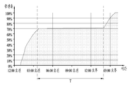
도 7a에 도시된 바와 같이 무선 전력 수신기(200)가 70%까지 충전하고 충전을 미쳐 완료하지 않은 상황에서 충전 대상(260)의 온도가 일정한 온도보다 올라하면, 무선 전력 수신기는 충전 대상(260)으로 전력 공급을 차단하는 무부하 상태로 충전을 진행한다.7A, if the temperature of the object to be charged 260 is higher than a certain temperature in a state where the
이 경우, 비교 례에 의하면, 무선 전력 송신기는 무선 전력 수신기(200)로부터 충전 완료 신호를 받지 않았을 뿐만 아니라 무선 전력 수신기(200)가 낮은 전력으로 계속해서 전력을 충전하는 것으로 인식하여, 무선 전력 수신기(200)로 전력을 계속 공급한다. 따라서, 무선 전력 수신기(200)의 충전율이 증가하지 않은 상태로 즉, 무선 전력 수신기(200)의 충전 대상(260)에 전력이 충전되지 않은 상태로 장시간(T) 예를 들어 10시간 이상 동안 불필요하게 전력이 소모될 뿐만 아니라 무선 전력 수신기(200)의 자체 온도가 증가하는 문제점이 있다.In this case, according to a comparative example, the wireless power transmitter not only receives the charge completion signal from the
그러나, 실시 예에 의하면, 무선 전력 송신기(100)가 무선 전력 수신기(200)로부터 충전 완료 신호를 받지 않았다고 하더라도, 전술한 4가지의 조건 즉, 코일 전류가 레일 전류보다 큰 첫 번째 조건, 무선 전력 수신기(200)의 충전율이 제1 소정 시간 동안 일정하게 유지되는 두 번째 조건, 무선 전력 수신기(200)로부터 충전 완료 신호가 제2 소정 시간 동안 수신되지 않은 세 번째 조건, 또는 무선 전력 송신기(200)의 온도가 상한 임계 범위 내에서 일정 시간 유지되는 네 번째 조건 중에서 적어도 2개가 만족되는가를 송신 제어부(140)가 검사한다. 이때, 적어도 2개의 조건이 만족될 때, 송신 제어부(140)는 전력을 일시적으로 무선 전력 수신기(200)로 전송하지 않은 이후 다시 전력의 공급을 재개하는 동작을 적어도 일회 예를 들어, 2회 정도 반복한다. 따라서, 일시적으로 전력 공급이 차단됨으로 인해, 무선 전력 수신기(200) 특히 충전 대상(260)의 온도가 수 ℃ 정도 떨어질 수 있어, 무선 전력 수신기(200)의 충전 시간이 도 7a의 비교 례 대비 도 8a에 도시된 바와 같이 상당히 단축될 수 있고, 불필요한 전력 소모를 줄일 수 있고, 무선 전력 수신기(200)의 충전 시간을 대폭 줄일 수 있다.However, according to the embodiment, even if the
전술한 실시 예에 의한 무선 전력 송신기, 무선 전력 수신기, 무선 전력 송신 방법은, 무선 전력 송신기로부터 무선 전력 수신기로 자기 유도 방식에 의해 전력을 무선으로 전송하는 경우에 국한되어 설명되었다. 그러나, 실시 예는 이에 국한되지 않는다. 즉, 전술한 실시 예에 의한 무선 전력 송신기, 무선 전력 수신기, 무선 전력 송신 방법은 자기 유도 방식 대신에 자기 공진 방식 또는 단파장 무선 주파수를 이용한 RF 전송 방식에 의해 무선 전력 송신기로부터 무선 전력 수신기로 전력을 무선으로 전송하는 경우에도 적용될 수 있음은 물론이다.The wireless power transmitter, the wireless power receiver, and the wireless power transmission method according to the above-described embodiments have been described only when wirelessly transmitting power from a wireless power transmitter to a wireless power receiver by a magnetic induction method. However, the embodiment is not limited to this. That is, in the wireless power transmitter, the wireless power receiver, and the wireless power transmission method according to the above-described embodiments, power is transmitted from the wireless power transmitter to the wireless power receiver by a self-resonance method or an RF transmission method using short- The present invention can also be applied to wireless transmission.
전술한 실시 예에 따른 무선 전력 송신 방법은 컴퓨터에서 실행되기 위한 프로그램으로 제작되어 컴퓨터가 읽을 수 있는 기록 매체에 저장될 수 있으며, 컴퓨터가 읽을 수 있는 기록 매체의 예로는 ROM, RAM, CD-ROM, 자기 테이프, 플로피디스크, 광 데이터 저장장치 등이 있으며, 또한 캐리어 웨이브(예를 들어 인터넷을 통한 전송)의 형태로 구현되는 것도 포함한다.The wireless power transmission method according to the above embodiments may be implemented as a program for execution in a computer and stored in a computer-readable recording medium. Examples of the computer-readable recording medium include a ROM, a RAM, a CD-ROM , A magnetic tape, a floppy disk, an optical data storage device, and the like, and may also be implemented in the form of a carrier wave (for example, transmission over the Internet).
컴퓨터가 읽을 수 있는 기록 매체는 네트워크로 연결된 컴퓨터 시스템에 분산되어, 분산방식으로 컴퓨터가 읽을 수 있는 코드가 저장되고 실행될 수 있다. 그리고, 상술한 방법을 구현하기 위한 기능적인(function) 프로그램, 코드 및 코드 세그먼트들은 실시예가 속하는 기술분야의 프로그래머들에 의해 용이하게 추론될 수 있다.The computer readable recording medium may be distributed over a networked computer system so that computer readable code can be stored and executed in a distributed manner. And, functional program, code, and code segments for implementing the above-described method can be easily inferred by programmers in the technical field to which the embodiment belongs.
전술한 실시 예에 의한 무선 전력 송신기(100)는 다양한 장치에서 포함되어, 무선 전력 수신기(200)로 전력을 무선으로 전송할 수 있다. 이하, 무선 전력 송신기(100)가 차량에 적용(또는, 장착)될 경우, 무선 전력 송신기(100)와 연계된 차량의 구성 및 동작에 대해 첨부된 도 9를 참조하여 다음과 같이 설명한다.The
도 9는 실시 예에 의한 무선 전력 송신기(100)와 연계된 차량(400)의 개략적인 블럭도를 나타낸다.9 shows a schematic block diagram of a
도 9에 도시된 차량(400)은 벅 변환부(buck converter)(122A), 센서(124A), 보호부(402), 입력 전압 모니터링(monitoring)부(404), 인터페이스(interface)부(406), 캔(CAN:Controller Area Network) 트랜시버(transceiver)(408), 디스플레이부(410), 제1 레귤레이터(412), 신호 합성부(414), 제2 레귤레이터(416) 및 주 제어부(418)를 포함할 수 있다.9 includes a
보호부(402)는 차량(400)의 배터리(미도시)로부터 공급되는 전압(BAT)을 벅 변환부(122A)로 출력한다. 이때, 보호부(402)는 배터리로부터 공급될 수 있는 과전압이나 역 전압으로부터 벅 변환부(122A)를 보호하는 역할을 한다.The
도 9에 도시된 벅 변환부(122A) 및 센서(124A)는 도 3에 도시된 레벨 변환부(122) 및 전력 센서(124) 각각의 실시 예에 해당한다. 벅 변환부(122A)는 보호부(402)를 통해 배터리로부터 공급되는 공급 전력의 레벨을 변환하고, 변환된 레벨을 갖는 신호를 전력 신호로서 센서(124A)로 출력한다. 센서(124A)는 벅 변환부(122A)에서 변환된 레벨을 갖고 출력되는 전력 신호의 전압/전류를 측정하여 출력단자 OUT1을 통해 송신 제어부(140)로 제공할 수 있다.The
입력 전압 모니터링부(404)는 입력단자 IN1을 통해 스마트키 신호 또는 점화 신호가 들어오는가를 모니터링하고, 모니터링된 결과를 주 제어부(418)로 출력한다. 여기서, 스마트키 신호란, 차량(400)의 무선 전력 송신기(100)가 무선으로 전력 신호를 무선 전력 수신기(200)로 제공하는 행위를 강제로 멈추고자 하는 사용자가 스마트키(미도시)를 이용하여 발생시키는 신호를 의미한다. 예를 들어, 무선 전력 신호를 강제로 멈추고자 할 경우, 제1 논리 레벨(예를 들어 "저" 논리 레벨)의 스마트키 신호가 발생되고, 그렇지 않을 경우 제2 논리 레벨(예를 들어 "고" 논리 레벨)의 스마트키 신호가 발생될 수 있다. 또한, 점화 신호란, 차량(400)의 시동을 걸 때 발생되는 신호를 의미하며, 예를 들어 시동이 걸릴 때 제2 논리 레벨(예를 들어, "고" 논리 레벨)의 점화 신호가 발생되고, 그렇지 않을 경우 제1 논리 레벨(예를 들어 "저" 논리 레벨)의 점화 신호가 발생될 수 있다.The input
또한, 입력 전압 모니터링부(404)로부터 발생되는 모니터링된 결과를 이용하여, 주 제어부(418)는 차량의 시동이 걸렸는가 및 사용자가 무선 전력 송신을 강제로 멈추고자하는가를 인식하고, 인식된 결과를 출력단자 OUT4를 통해 송신 제어부(140)로 출력한다. 이때, 송신 제어부(140)는 주 제어부(418)로부터 출력된 인식된 결과에 따라 무선 송신기(100)가 무선 전력 전송을 멈추도록 한다.Also, by using the monitored result generated from the input
주 제어부(418)는 마스터(master) 제어부의 역할을 하고, 송신 제어부(140)는 슬레이브(slave) 제어부의 역할을 한다. 즉, 송신 제어부(140)는 주 제어부(418)의 제어를 받는다. 이를 위해, 주 제어부(418)와 송신 제어부(140)는 SPI(Serial Peripheral Interface) 통신을 하거나, I2C 통신을 할 수 있다.The
또한, 주 제어부(418)는 스마트키 신호나 점화 신호가 발생되지 않은 상태에서도, 제2 논리 레벨의 신호를 발생하여 신호 합성부(414)로 출력할 수 있다.Also, the
센서(124A)에서 측정된 전압/전류의 레벨을 통해 벅 변환부(122A)에서 레벨 변환된 공급 전력의 레벨이 높거나 낮다고 판단될 때, 주 제어부(418)는 제1 제어 신호(C1)를 통해 벅 변환부(122A)에서 변환시킬 레벨을 조정할 수 있다.When it is determined that the level of the power level-converted by the
또한, 인터페이스부(406)는 입력단자 IN1을 통해 들어온 스마트키 신호 또는 점화 신호를 신호 합성부(414)로 출력하는 역할을 한다. 신호 합성부(414)는 인터페이스부(406)로부터 제2 논리 레벨의 스마트키 신호가 출력되거나, 주 제어부(418)로부터 제2 논리 레벨의 제어 신호가 들어오면, 제1 레귤레이터(412)에서 레벨 조정하지 않도록 하거나, 레벨 조정된 전압이 출력되지 않도록 할 수 있다. 이를 위해, 신호 합성부(414)는 논리합(OR) 게이트로 구현될 수 있다.The
제1 레귤레이터(412)는 보호부(402)를 통해 배터리로부터 제공되는 공급 전압의 레벨을 소정의 레벨로 변환하고, 변환된 레벨을 갖는 공급 전압을 출력단자 OUT2를 통해 무선 전력 송신기(100)의 각 부로 출력한다. 여기서, 소정의 레벨은 6.5볼트일 수 있으나 실시 예는 이에 국한되지 않는다. 예를 들어, 신호 합성부(414)로부터 출력되는 "고" 논리 레벨의 제어 전압에 응답하여, 제1 레귤레이터(412)는 전술한 레벨 변환 동작을 수행하지 않을 수 있다.The
제2 레귤레이터(416)는 제1 레귤레이터(412)로부터 출력되는 공급 전압의 레벨을 다시 조정하여, 원하는 레벨을 갖는 신호를 출력단자 OUT3을 통해 송신 제어부(140)로 출력하거나 주 제어부(418)로 출력할 수 있다. 예를 들어, 제2 레귤레이터(416)는 공급 전압의 레벨을 변환하여, 변환된 레벨 예를 들어, 5.5 볼트의 신호를 주 제어부(418)로 출력하고, 출력단자 OUT3을 통해 변환된 레벨 예를 들어, 3.3 볼트의 신호를 송신 제어부(140)로 출력할 수 있다.The
전술한 제1 및 제2 레귤레이터(412, 416) 각각에서 변환되는 레벨은 고정되고 벅 변환부(122A)에서 변환되는 레벨은 주 제어부(418)의 제어하여 가변될 수 있다.The level converted at each of the first and
한편, 캔 트랜시버(408)는 차량(400)의 통신하기 위한 캔 신호(CAN)를 받고, 이를 통해 주 제어부(418)와 내부적으로 통신을 수행할 수 있다.Meanwhile, the
디스플레이부(410)는 주 제어부(418)의 제어 하에, 무선 전력 수신기(200)에서 충전 중인 상황을 사용자에게 시각적으로 보여줄 수도 있다.The
본 발명은 본 발명의 정신 및 필수적 특징을 벗어나지 않는 범위에서 다른 특정한 형태로 구체화될 수 있음은 당업자에게 자명하다.It will be apparent to those skilled in the art that the present invention may be embodied in other specific forms without departing from the spirit or essential characteristics thereof.
따라서, 상기의 상세한 설명은 모든 면에서 제한적으로 해석되어서는 아니되고 예시적인 것으로 고려되어야 한다. 본 발명의 범위는 첨부된 청구항의 합리적 해석에 의해 결정되어야 하고, 본 발명의 등가적 범위 내에서의 모든 변경은 본 발명의 범위에 포함된다.Accordingly, the above description should not be construed in a limiting sense in all respects and should be considered illustrative. The scope of the present invention should be determined by rational interpretation of the appended claims, and all changes within the scope of equivalents of the present invention are included in the scope of the present invention.
100: 무선 전력 송신기
110: 전원부
120: 전력 변환부
122: 레벨 변환부
124: 전력 센서
126: 증폭부
130: 전력 전송부
132: 주파수 구동부
134: 코일 선택부
136: 송신 코일단
140: 송신 제어부
150: 복조부
162, 164: 센서
166: 온도 측정부
168: 비교부
200: 무선 전력 수신기
210: 수신 코일
220: 정류부
230: 전압 제어부
240: 수신 제어부
250: 변조부
260: 충전 대상
400: 차량
402: 보호부
404: 입력 전압 모니터링부
406: 인터페이스부
408: 캔 트랜시버
410: 디스플레이부
412: 제1 레귤레이터
414: 신호 합성부
416: 제2 레귤레이터
418: 주 제어부100: wireless power transmitter 110: power supply unit
120: power conversion unit 122: level conversion unit
124: power sensor 126:
130: power transfer unit 132: frequency driver
134: coil selector 136: transmitting coil
140: transmission control unit 150:
162, 164: sensor 166: temperature measuring unit
168: comparator 200: wireless power receiver
210: receiving coil 220: rectifying part
230: Voltage controller 240: Receiver controller
250: Modulation part 260: Charging object
400: vehicle 402: protection unit
404: input voltage monitoring unit 406: interface unit
408: can transceiver 410: display unit
412: First regulator 414: Signal synthesizer
416: second regulator 418:
Claims (14)
공급 전력의 세기를 변환하여 상기 전력 신호로서 출력하는 전력 변환부;
상기 무선 전력 수신기가 충전을 완료하지 않고 무부하 상태로 충전을 진행하는가를 검사하고, 상기 검사된 결과에 따라 상기 무선 전력 수신기로의 상기 전력 신호의 공급을 일시적으로 중단한 후 재개시키는 송신 제어부; 및
상기 전력 신호를 상기 무선 전력 수신기로 전송하는 적어도 하나의 송신 코일을 갖는 송신 코일단을 포함하는 무선 전력 송신기.1. A wireless power transmitter for wirelessly transmitting a power signal to a wireless power receiver,
A power conversion unit for converting the intensity of the power supply and outputting the power as the power signal;
A transmission control unit for checking whether the wireless power receiver completes charging and proceeding to charge in a no-load state, and temporarily stopping the supply of the power signal to the wireless power receiver according to the checked result and then restarting the power supply; And
And a transmit coil having at least one transmit coil for transmitting the power signal to the wireless power receiver.
주파수 구동부; 및
상기 무선 전력 수신기로부터 전송되어 상기 송신 코일단을 통해 들어온 피드백 신호를 복조하는 복조부를 더 포함하고,
상기 송신 제어부는
상기 복조부에서 복조된 피드백 신호에 따라 상기 주파수 구동부를 제어하여 상기 송신 코일단으로 전달될 상기 전력 신호의 주파수를 변경하는 무선 전력 송신기.2. The wireless power transmitter of claim 1,
A frequency driver; And
Further comprising: a demodulation unit that demodulates a feedback signal transmitted from the wireless power receiver and received through the transmission coil,
The transmission control unit
And controls the frequency driver according to a feedback signal demodulated by the demodulator to change a frequency of the power signal to be transmitted to the transmission coil.
상기 공급 전력의 레벨을 변환하는 레벨 변환부; 및
상기 레벨 변환된 공급 전력의 전압/전류를 측정하는 전력 센서를 포함하고,
상기 송신 제어부는 상기 전력 센서에서 측정된 결과에 따라 상기 레벨 변환부로의 상기 공급 전력의 공급을 차단시키는 무선 전력 송신기.4. The apparatus of claim 3, wherein the power converter
A level converting unit for converting the level of the supplied power; And
And a power sensor for measuring voltage / current of the level-converted supply power,
And the transmission control unit interrupts supply of the supply power to the level conversion unit according to a result of measurement by the power sensor.
상기 레벨 변환부로부터 상기 전력 센서로 흐르는 레일 전류의 레벨을 측정하는 제1 센서;
상기 송신 코일단 중에서 상기 무선 전력 수신기가 무선으로 연결된 송신 코일에 흐르는 코일 전류의 레벨을 측정하는 제2 센서; 및
상기 제1 및 제2 센서에서 측정된 결과를 비교하는 비교부를 더 포함하고,
상기 송신 제어부는 상기 비교부에서 비교된 결과를 이용하여, 상기 무선 전력 수신기가 무부하 상태로 충전을 진행하는가를 검사하는 무선 전력 송신기.5. The apparatus of claim 4, wherein the wireless power transmitter
A first sensor for measuring a level of a rail current flowing from the level converter to the power sensor;
A second sensor for measuring a level of a coil current flowing through a transmission coil of the wireless transmission unit, the wireless sensor being wirelessly connected to the wireless power receiver; And
Further comprising a comparator for comparing the measured results of the first and second sensors,
Wherein the transmission control unit checks whether the wireless power receiver proceeds charging in a no-load state using the comparison result in the comparison unit.
상기 송신 제어부는 상기 온도 측정부에서 측정된 온도가 상한 임계 범위 내에서 일정시간 유지되는가를 체크하고, 체크된 결과에 따라 상기 무선 전력 수신기가 무부하 상태로 충전을 진행하는가를 검사하는 무선 전력 송신기.6. The wireless power transmitter of claim 5, further comprising a temperature measuring unit for measuring a temperature of the wireless power transmitter,
Wherein the transmission control unit checks whether the temperature measured by the temperature measuring unit is maintained within an upper limit threshold range for a predetermined period of time and inspects whether the wireless power receiver progresses charging in a no-load state according to the checked result.
상기 송신 코일단에서 해당하는 송신 코일과 전자기장에 의해 결합되는 수신 코일;
상기 수신 코일을 통해 상기 무선 전력 송신기로 전송될 상기 피드백 신호를 변조하는 변조부;
상기 수신 코일을 통해 수신된 상기 전력 신호를 정류하여 충전 대상으로 제공하는 정류부; 및
상기 충전 대상의 온도가 상기 충전 대상의 온도가 한계 온도보다 클 때 상기 정류부를 제어하여, 상기 충전 대상으로의 상기 전력 신호의 공급을 차단하여 무부하 상태의 충전을 진행하며, 상기 피드백 신호를 발생하는 수신 제어부를 포함하는 무선 전력 수신기.A wireless power receiver as claimed in any one of claims 1 to 7, wherein the power signal is wirelessly transmitted from a wireless power transmitter,
A receiving coil coupled to the corresponding transmitting coil at the transmitting coil by an electromagnetic field;
A modulator for modulating the feedback signal to be transmitted to the wireless power transmitter through the receive coil;
A rectifier for rectifying the power signal received through the receiving coil to provide a charging object; And
When the temperature of the object to be charged is higher than the limit temperature, the rectifying unit is controlled to interrupt the supply of the electric power signal to the object to be charged, thereby progressing charging in a no-load state, A wireless power receiver comprising a receiving control.
공급 전력의 세기를 변환하여 전력 신호를 생성하는 단계; 및
상기 무선 전력 수신기가 충전을 완료하지 않고 무부하 상태로 충전을 진행할 때, 상기 전력 신호의 공급을 일시적으로 중단한 후 재개하는 단계를 포함하는 무선 전력 송신 방법.A method for wirelessly transmitting power from a wireless power transmitter to a wireless power receiver,
Converting the intensity of the power supply to generate a power signal; And
And temporarily stopping and resuming the supply of the power signal when the wireless power receiver proceeds charging in a no-load state without completing charging.
코일 전류가 레일 전류보다 클 때;
상기 무선 전력 수신기의 완충에 못 미치는 충전율이 제1 소정 시간 동안 일정하게 유지될 때;
상기 무선 전력 수신기로부터 충전 완료 신호가 제2 소정 시간 동안 수신되지 않을 때; 또는
상기 무선 전력 송신기의 온도가 상한 임계 범위 내에서 일정 시간 유지될 때 중에서 적어도 2개가 만족될 때, 상기 무선 전력 수신기가 무부하 상태로 충전을 진행하는 것으로 결정하는 무선 전력 송신 방법.11. The method of claim 10, wherein the step of checking whether to proceed with charging in the no-load state
When the coil current is greater than the rail current;
When the charge rate that is less than the buffer of the wireless power receiver is kept constant for a first predetermined time;
When a charge completion signal from the wireless power receiver is not received for a second predetermined time; or
Wherein the wireless power receiver determines that the wireless power receiver proceeds with charging in a no-load state when at least two of the time when the temperature of the wireless power transmitter is maintained within the upper critical range is satisfied.
Priority Applications (6)
| Application Number | Priority Date | Filing Date | Title |
|---|---|---|---|
| KR1020150171427A KR20170065236A (en) | 2015-12-03 | 2015-12-03 | Wireless Charging apparatus, and Method for wirelessly transmitting power, and recording media therefor |
| CN201680070847.4A CN108450042A (en) | 2015-12-03 | 2016-09-08 | Wireless charging device, wireless power transmission method thereby, and recording medium therefor |
| EP16870894.9A EP3386066A4 (en) | 2015-12-03 | 2016-09-08 | WIRELESS CHARGING DEVICE, WIRELESS POWER TRANSMISSION METHOD THEREFOR, AND RECORDING MEDIUM FOR THE METHOD |
| PCT/KR2016/010078 WO2017094997A1 (en) | 2015-12-03 | 2016-09-08 | Wireless charging device, wireless power transmission method therefor, and recording medium for same |
| JP2018528617A JP2018536377A (en) | 2015-12-03 | 2016-09-08 | Wireless charging apparatus, wireless power transmission method thereof, and recording medium therefor |
| US15/780,979 US20180351406A1 (en) | 2015-12-03 | 2016-09-08 | Wireless charging device, wireless power transmission method therefor, and recording medium for same |
Applications Claiming Priority (1)
| Application Number | Priority Date | Filing Date | Title |
|---|---|---|---|
| KR1020150171427A KR20170065236A (en) | 2015-12-03 | 2015-12-03 | Wireless Charging apparatus, and Method for wirelessly transmitting power, and recording media therefor |
Publications (1)
| Publication Number | Publication Date |
|---|---|
| KR20170065236A true KR20170065236A (en) | 2017-06-13 |
Family
ID=58797061
Family Applications (1)
| Application Number | Title | Priority Date | Filing Date |
|---|---|---|---|
| KR1020150171427A Withdrawn KR20170065236A (en) | 2015-12-03 | 2015-12-03 | Wireless Charging apparatus, and Method for wirelessly transmitting power, and recording media therefor |
Country Status (6)
| Country | Link |
|---|---|
| US (1) | US20180351406A1 (en) |
| EP (1) | EP3386066A4 (en) |
| JP (1) | JP2018536377A (en) |
| KR (1) | KR20170065236A (en) |
| CN (1) | CN108450042A (en) |
| WO (1) | WO2017094997A1 (en) |
Cited By (6)
| Publication number | Priority date | Publication date | Assignee | Title |
|---|---|---|---|---|
| WO2019022367A1 (en) * | 2017-07-24 | 2019-01-31 | 엘지이노텍(주) | Method and device for controlling heat generated during wireless charging |
| WO2019132223A1 (en) * | 2017-12-28 | 2019-07-04 | 엘지이노텍(주) | Feedback signal processing device for wireless charging transmitter |
| KR20200008319A (en) * | 2018-07-16 | 2020-01-28 | 삼성전자주식회사 | Electronic device for receiving wireless power and method for wireless charging thereof |
| KR20200054242A (en) * | 2018-03-29 | 2020-05-19 | 녹9 아이피 에이비 | Inspection device and method related to inspection of wireless power transmission device |
| WO2020166854A1 (en) * | 2019-02-15 | 2020-08-20 | 삼성전자 주식회사 | Wireless power transmission apparatus and method |
| WO2023068515A1 (en) * | 2021-10-22 | 2023-04-27 | 삼성전자 주식회사 | Electronic device for controlling charging of battery on basis of change in temperature, and method therefor |
Families Citing this family (13)
| Publication number | Priority date | Publication date | Assignee | Title |
|---|---|---|---|---|
| EP3346581B1 (en) * | 2017-01-04 | 2023-06-14 | LG Electronics Inc. | Wireless charger for mobile terminal in vehicle |
| JP6967867B2 (en) * | 2017-04-04 | 2021-11-17 | キヤノン株式会社 | Power transmission equipment and its control method, as well as programs |
| KR20180117396A (en) * | 2017-04-19 | 2018-10-29 | 재단법인 다차원 스마트 아이티 융합시스템 연구단 | Wireless charging system for selectively using antenna |
| KR20190054416A (en) * | 2017-11-13 | 2019-05-22 | 삼성전기주식회사 | Wireless power transmission apparatus |
| US11159058B2 (en) * | 2017-12-01 | 2021-10-26 | Transferfi Pte. Ltd. | Wireless power transmission |
| CN109525017B (en) * | 2018-12-21 | 2020-07-07 | 惠州Tcl移动通信有限公司 | Charging circuit and electronic device |
| KR102823731B1 (en) * | 2019-04-16 | 2025-06-23 | 삼성전자주식회사 | Wireless power receiver and method for supplying wireless power thereof |
| CN109995121B (en) * | 2019-05-05 | 2023-11-28 | 中国科学技术大学 | Power-optimized many-to-many wireless charging equipment and control method |
| CN112104092B (en) * | 2020-05-22 | 2022-08-23 | 未来穿戴技术有限公司 | Management method for wireless charging of neck massager, neck massager and mobile device |
| WO2022020177A1 (en) * | 2020-07-20 | 2022-01-27 | General Electric Company | Time slicing wireless charging |
| CN114157050A (en) * | 2022-01-04 | 2022-03-08 | 深圳市力生美半导体股份有限公司 | Wireless charging circuit and method with low standby power consumption |
| TWI872902B (en) * | 2024-01-03 | 2025-02-11 | 台達電子工業股份有限公司 | Detecting method and power transmitter in wireless charging system |
| CN120262717A (en) | 2024-01-03 | 2025-07-04 | 台达电子工业股份有限公司 | Power transmitter and detection method in wireless charging system |
Family Cites Families (17)
| Publication number | Priority date | Publication date | Assignee | Title |
|---|---|---|---|---|
| JP2000102187A (en) * | 1998-09-22 | 2000-04-07 | Shinano Kenshi Co Ltd | Battery charger |
| KR100792310B1 (en) * | 2005-04-07 | 2008-01-07 | 엘에스전선 주식회사 | Solid State Charging System with Feedback Control |
| US7310245B2 (en) * | 2005-04-22 | 2007-12-18 | Noboru Ohbo | Electric power transmission device and electric power transmission method |
| JP5049018B2 (en) * | 2007-01-09 | 2012-10-17 | ソニーモバイルコミュニケーションズ株式会社 | Non-contact charger |
| JP2008178195A (en) * | 2007-01-17 | 2008-07-31 | Seiko Epson Corp | Power transmission control device, power reception control device, non-contact power transmission system, power transmission device, power reception device, and electronic device |
| JP2010016985A (en) * | 2008-07-03 | 2010-01-21 | Sanyo Electric Co Ltd | Method of data transmission in electric power transmission, and charging stand and battery built-in device using the method |
| MY160103A (en) * | 2008-10-03 | 2017-02-28 | Access Business Group Int Llc | Power system |
| KR20110103297A (en) * | 2010-03-12 | 2011-09-20 | 삼성전자주식회사 | Wireless power charging method and device |
| CN103782481B (en) * | 2011-09-14 | 2017-02-15 | 松下电器产业株式会社 | Non-contact power receiving device and non-contact power transmission device |
| JP5512628B2 (en) * | 2011-10-19 | 2014-06-04 | 東芝テック株式会社 | Power transmission device, power transmission device, power reception device, and power transmission method |
| KR101337332B1 (en) * | 2012-02-10 | 2013-12-06 | 전자부품연구원 | Mobile emotion sensing apparatus and method for charging |
| JP5847651B2 (en) * | 2012-06-01 | 2016-01-27 | 株式会社東芝 | Power receiving device and power transmitting / receiving system |
| JP2014217115A (en) * | 2013-04-23 | 2014-11-17 | パナソニックインテレクチュアル プロパティ コーポレーション オブアメリカPanasonic Intellectual Property Corporation of America | Electronic apparatus and battery charger |
| CN104124769B (en) * | 2013-04-28 | 2019-04-05 | 海尔集团技术研发中心 | Wireless power supply control system and method |
| KR102082415B1 (en) * | 2013-05-27 | 2020-02-27 | 엘지전자 주식회사 | Wireless power transmitter and method of wireless power transmittion |
| CN104467989B (en) * | 2014-12-25 | 2017-03-15 | 东南大学 | A kind of radio energy transmission system receiving terminal detection method of self-identifying load |
| CN104734315B (en) * | 2015-04-01 | 2016-08-10 | 中国矿业大学 | A wireless charging control method for an electric vehicle battery |
-
2015
- 2015-12-03 KR KR1020150171427A patent/KR20170065236A/en not_active Withdrawn
-
2016
- 2016-09-08 US US15/780,979 patent/US20180351406A1/en not_active Abandoned
- 2016-09-08 WO PCT/KR2016/010078 patent/WO2017094997A1/en not_active Ceased
- 2016-09-08 JP JP2018528617A patent/JP2018536377A/en active Pending
- 2016-09-08 CN CN201680070847.4A patent/CN108450042A/en active Pending
- 2016-09-08 EP EP16870894.9A patent/EP3386066A4/en not_active Withdrawn
Cited By (10)
| Publication number | Priority date | Publication date | Assignee | Title |
|---|---|---|---|---|
| WO2019022367A1 (en) * | 2017-07-24 | 2019-01-31 | 엘지이노텍(주) | Method and device for controlling heat generated during wireless charging |
| WO2019132223A1 (en) * | 2017-12-28 | 2019-07-04 | 엘지이노텍(주) | Feedback signal processing device for wireless charging transmitter |
| KR20190079815A (en) * | 2017-12-28 | 2019-07-08 | 엘지이노텍 주식회사 | Apparatus For Handling Feedback Signal In Wireless Power Transmitter |
| KR20200054242A (en) * | 2018-03-29 | 2020-05-19 | 녹9 아이피 에이비 | Inspection device and method related to inspection of wireless power transmission device |
| KR20200008319A (en) * | 2018-07-16 | 2020-01-28 | 삼성전자주식회사 | Electronic device for receiving wireless power and method for wireless charging thereof |
| CN112534673A (en) * | 2018-07-16 | 2021-03-19 | 三星电子株式会社 | Electronic device for receiving wireless power and wireless charging method thereof |
| CN112534673B (en) * | 2018-07-16 | 2024-07-26 | 三星电子株式会社 | Electronic device for receiving wireless power and wireless charging method thereof |
| WO2020166854A1 (en) * | 2019-02-15 | 2020-08-20 | 삼성전자 주식회사 | Wireless power transmission apparatus and method |
| KR20200099751A (en) * | 2019-02-15 | 2020-08-25 | 삼성전자주식회사 | Wireless power transmitting device and method |
| WO2023068515A1 (en) * | 2021-10-22 | 2023-04-27 | 삼성전자 주식회사 | Electronic device for controlling charging of battery on basis of change in temperature, and method therefor |
Also Published As
| Publication number | Publication date |
|---|---|
| EP3386066A1 (en) | 2018-10-10 |
| EP3386066A4 (en) | 2019-08-07 |
| WO2017094997A1 (en) | 2017-06-08 |
| JP2018536377A (en) | 2018-12-06 |
| US20180351406A1 (en) | 2018-12-06 |
| CN108450042A (en) | 2018-08-24 |
Similar Documents
| Publication | Publication Date | Title |
|---|---|---|
| KR20170065236A (en) | Wireless Charging apparatus, and Method for wirelessly transmitting power, and recording media therefor | |
| US11936209B2 (en) | Foreign substance detection method for wireless charging and apparatus therefor | |
| KR102051682B1 (en) | Apparatus and method for detecting foreign object in wireless power transmitting system | |
| EP3553915B1 (en) | Method for detecting foreign object and apparatus for same | |
| US10797507B2 (en) | Wireless charging method, and apparatus and system therefor | |
| US9496083B2 (en) | Wireless power transmitter, wireless power receiver, and methods of controlling the same | |
| US20180301936A1 (en) | Multi-coil wireless charging method and device and system therefor | |
| JP6901491B2 (en) | A wireless power device equipped with multiple transmission coils and its driving method | |
| US11271432B2 (en) | Wireless power control method and device | |
| KR20170118571A (en) | Foreign Object Detection Method and Apparatus and System therefor | |
| KR20190087733A (en) | Wireless Charging Coil With High Quality Factor | |
| KR20190026244A (en) | Wireless Power Transmission Method and Apparatus therefor | |
| US20190245387A1 (en) | Wireless power control method and apparatus for wireless charging | |
| KR102653290B1 (en) | Apparatus and method for detecting foreign object in wireless power transmitting system | |
| KR20180010796A (en) | Foreign Object Detection Method and Apparatus and System therefor | |
| KR20180038205A (en) | Foreign Object Detection Method and Apparatus and System therefor | |
| KR20190134566A (en) | Apparatus and method for detecting foreign object in wireless power transmitting system | |
| KR20190082483A (en) | Near Field Communication Signal Detection Method and Apparatus Therefor | |
| KR20190026424A (en) | Wireless Charging Method and Apparatus and System therefor | |
| KR20170140895A (en) | Foreign Object Detection Method and Apparatus and System therefor | |
| KR20190083584A (en) | Noise Reduction Wireless Power Transmission Method and Apparatus | |
| KR20190112979A (en) | Method and apparatus for bi-directional communication in wireless power receiver | |
| KR20190090548A (en) | Wireless Power Transmission Method and Apparatus for Protecting Over Temperature | |
| KR101773092B1 (en) | Method for wireless power transmission and apparatus therefor | |
| KR20190070557A (en) | Wireless Power Transmitter With Near Field Communication Function |
Legal Events
| Date | Code | Title | Description |
|---|---|---|---|
| PA0109 | Patent application |
St.27 status event code: A-0-1-A10-A12-nap-PA0109 |
|
| R18-X000 | Changes to party contact information recorded |
St.27 status event code: A-3-3-R10-R18-oth-X000 |
|
| PG1501 | Laying open of application |
St.27 status event code: A-1-1-Q10-Q12-nap-PG1501 |
|
| P22-X000 | Classification modified |
St.27 status event code: A-2-2-P10-P22-nap-X000 |
|
| R18-X000 | Changes to party contact information recorded |
St.27 status event code: A-3-3-R10-R18-oth-X000 |
|
| P22-X000 | Classification modified |
St.27 status event code: A-2-2-P10-P22-nap-X000 |
|
| P22-X000 | Classification modified |
St.27 status event code: A-2-2-P10-P22-nap-X000 |
|
| R18-X000 | Changes to party contact information recorded |
St.27 status event code: A-3-3-R10-R18-oth-X000 |
|
| PC1203 | Withdrawal of no request for examination |
St.27 status event code: N-1-6-B10-B12-nap-PC1203 |
|
| PN2301 | Change of applicant |
St.27 status event code: A-3-3-R10-R13-asn-PN2301 St.27 status event code: A-3-3-R10-R11-asn-PN2301 |
|
| P22-X000 | Classification modified |
St.27 status event code: A-2-2-P10-P22-nap-X000 |
|
| P22-X000 | Classification modified |
St.27 status event code: A-2-2-P10-P22-nap-X000 |