KR20170062441A - Camera assembly - Google Patents
Camera assembly Download PDFInfo
- Publication number
- KR20170062441A KR20170062441A KR1020177004461A KR20177004461A KR20170062441A KR 20170062441 A KR20170062441 A KR 20170062441A KR 1020177004461 A KR1020177004461 A KR 1020177004461A KR 20177004461 A KR20177004461 A KR 20177004461A KR 20170062441 A KR20170062441 A KR 20170062441A
- Authority
- KR
- South Korea
- Prior art keywords
- lens
- assembly
- optical axis
- support structure
- lens assembly
- Prior art date
- Legal status (The legal status is an assumption and is not a legal conclusion. Google has not performed a legal analysis and makes no representation as to the accuracy of the status listed.)
- Withdrawn
Links
Images


Classifications
-
- G—PHYSICS
- G02—OPTICS
- G02B—OPTICAL ELEMENTS, SYSTEMS OR APPARATUS
- G02B27/00—Optical systems or apparatus not provided for by any of the groups G02B1/00 - G02B26/00, G02B30/00
- G02B27/64—Imaging systems using optical elements for stabilisation of the lateral and angular position of the image
- G02B27/646—Imaging systems using optical elements for stabilisation of the lateral and angular position of the image compensating for small deviations, e.g. due to vibration or shake
-
- F—MECHANICAL ENGINEERING; LIGHTING; HEATING; WEAPONS; BLASTING
- F03—MACHINES OR ENGINES FOR LIQUIDS; WIND, SPRING, OR WEIGHT MOTORS; PRODUCING MECHANICAL POWER OR A REACTIVE PROPULSIVE THRUST, NOT OTHERWISE PROVIDED FOR
- F03G—SPRING, WEIGHT, INERTIA OR LIKE MOTORS; MECHANICAL-POWER PRODUCING DEVICES OR MECHANISMS, NOT OTHERWISE PROVIDED FOR OR USING ENERGY SOURCES NOT OTHERWISE PROVIDED FOR
- F03G7/00—Mechanical-power-producing mechanisms, not otherwise provided for or using energy sources not otherwise provided for
- F03G7/06—Mechanical-power-producing mechanisms, not otherwise provided for or using energy sources not otherwise provided for using expansion or contraction of bodies due to heating, cooling, moistening, drying or the like
- F03G7/061—Mechanical-power-producing mechanisms, not otherwise provided for or using energy sources not otherwise provided for using expansion or contraction of bodies due to heating, cooling, moistening, drying or the like characterised by the actuating element
- F03G7/0614—Mechanical-power-producing mechanisms, not otherwise provided for or using energy sources not otherwise provided for using expansion or contraction of bodies due to heating, cooling, moistening, drying or the like characterised by the actuating element using shape memory elements
- F03G7/06143—Wires
-
- F—MECHANICAL ENGINEERING; LIGHTING; HEATING; WEAPONS; BLASTING
- F03—MACHINES OR ENGINES FOR LIQUIDS; WIND, SPRING, OR WEIGHT MOTORS; PRODUCING MECHANICAL POWER OR A REACTIVE PROPULSIVE THRUST, NOT OTHERWISE PROVIDED FOR
- F03G—SPRING, WEIGHT, INERTIA OR LIKE MOTORS; MECHANICAL-POWER PRODUCING DEVICES OR MECHANISMS, NOT OTHERWISE PROVIDED FOR OR USING ENERGY SOURCES NOT OTHERWISE PROVIDED FOR
- F03G7/00—Mechanical-power-producing mechanisms, not otherwise provided for or using energy sources not otherwise provided for
- F03G7/06—Mechanical-power-producing mechanisms, not otherwise provided for or using energy sources not otherwise provided for using expansion or contraction of bodies due to heating, cooling, moistening, drying or the like
- F03G7/063—Mechanical-power-producing mechanisms, not otherwise provided for or using energy sources not otherwise provided for using expansion or contraction of bodies due to heating, cooling, moistening, drying or the like characterised by the mechanic interaction
- F03G7/0636—Mechanical-power-producing mechanisms, not otherwise provided for or using energy sources not otherwise provided for using expansion or contraction of bodies due to heating, cooling, moistening, drying or the like characterised by the mechanic interaction with several elements connected in parallel
-
- G—PHYSICS
- G02—OPTICS
- G02B—OPTICAL ELEMENTS, SYSTEMS OR APPARATUS
- G02B7/00—Mountings, adjusting means, or light-tight connections, for optical elements
- G02B7/02—Mountings, adjusting means, or light-tight connections, for optical elements for lenses
-
- G—PHYSICS
- G02—OPTICS
- G02B—OPTICAL ELEMENTS, SYSTEMS OR APPARATUS
- G02B7/00—Mountings, adjusting means, or light-tight connections, for optical elements
- G02B7/02—Mountings, adjusting means, or light-tight connections, for optical elements for lenses
- G02B7/04—Mountings, adjusting means, or light-tight connections, for optical elements for lenses with mechanism for focusing or varying magnification
- G02B7/08—Mountings, adjusting means, or light-tight connections, for optical elements for lenses with mechanism for focusing or varying magnification adapted to co-operate with a remote control mechanism
-
- G—PHYSICS
- G02—OPTICS
- G02B—OPTICAL ELEMENTS, SYSTEMS OR APPARATUS
- G02B7/00—Mountings, adjusting means, or light-tight connections, for optical elements
- G02B7/02—Mountings, adjusting means, or light-tight connections, for optical elements for lenses
- G02B7/04—Mountings, adjusting means, or light-tight connections, for optical elements for lenses with mechanism for focusing or varying magnification
- G02B7/09—Mountings, adjusting means, or light-tight connections, for optical elements for lenses with mechanism for focusing or varying magnification adapted for automatic focusing or varying magnification
-
- G—PHYSICS
- G03—PHOTOGRAPHY; CINEMATOGRAPHY; ANALOGOUS TECHNIQUES USING WAVES OTHER THAN OPTICAL WAVES; ELECTROGRAPHY; HOLOGRAPHY
- G03B—APPARATUS OR ARRANGEMENTS FOR TAKING PHOTOGRAPHS OR FOR PROJECTING OR VIEWING THEM; APPARATUS OR ARRANGEMENTS EMPLOYING ANALOGOUS TECHNIQUES USING WAVES OTHER THAN OPTICAL WAVES; ACCESSORIES THEREFOR
- G03B3/00—Focusing arrangements of general interest for cameras, projectors or printers
- G03B3/10—Power-operated focusing
-
- G—PHYSICS
- G03—PHOTOGRAPHY; CINEMATOGRAPHY; ANALOGOUS TECHNIQUES USING WAVES OTHER THAN OPTICAL WAVES; ELECTROGRAPHY; HOLOGRAPHY
- G03B—APPARATUS OR ARRANGEMENTS FOR TAKING PHOTOGRAPHS OR FOR PROJECTING OR VIEWING THEM; APPARATUS OR ARRANGEMENTS EMPLOYING ANALOGOUS TECHNIQUES USING WAVES OTHER THAN OPTICAL WAVES; ACCESSORIES THEREFOR
- G03B5/00—Adjustment of optical system relative to image or object surface other than for focusing
- G03B5/02—Lateral adjustment of lens
-
- H—ELECTRICITY
- H04—ELECTRIC COMMUNICATION TECHNIQUE
- H04N—PICTORIAL COMMUNICATION, e.g. TELEVISION
- H04N23/00—Cameras or camera modules comprising electronic image sensors; Control thereof
- H04N23/50—Constructional details
- H04N23/54—Mounting of pick-up tubes, electronic image sensors, deviation or focusing coils
-
- H—ELECTRICITY
- H04—ELECTRIC COMMUNICATION TECHNIQUE
- H04N—PICTORIAL COMMUNICATION, e.g. TELEVISION
- H04N23/00—Cameras or camera modules comprising electronic image sensors; Control thereof
- H04N23/50—Constructional details
- H04N23/55—Optical parts specially adapted for electronic image sensors; Mounting thereof
-
- H—ELECTRICITY
- H04—ELECTRIC COMMUNICATION TECHNIQUE
- H04N—PICTORIAL COMMUNICATION, e.g. TELEVISION
- H04N23/00—Cameras or camera modules comprising electronic image sensors; Control thereof
- H04N23/57—Mechanical or electrical details of cameras or camera modules specially adapted for being embedded in other devices
-
- H—ELECTRICITY
- H04—ELECTRIC COMMUNICATION TECHNIQUE
- H04N—PICTORIAL COMMUNICATION, e.g. TELEVISION
- H04N23/00—Cameras or camera modules comprising electronic image sensors; Control thereof
- H04N23/60—Control of cameras or camera modules
- H04N23/68—Control of cameras or camera modules for stable pick-up of the scene, e.g. compensating for camera body vibrations
- H04N23/682—Vibration or motion blur correction
- H04N23/685—Vibration or motion blur correction performed by mechanical compensation
- H04N23/687—Vibration or motion blur correction performed by mechanical compensation by shifting the lens or sensor position
-
- H04N5/2254—
-
- H04N5/2257—
-
- H04N5/23287—
-
- G—PHYSICS
- G03—PHOTOGRAPHY; CINEMATOGRAPHY; ANALOGOUS TECHNIQUES USING WAVES OTHER THAN OPTICAL WAVES; ELECTROGRAPHY; HOLOGRAPHY
- G03B—APPARATUS OR ARRANGEMENTS FOR TAKING PHOTOGRAPHS OR FOR PROJECTING OR VIEWING THEM; APPARATUS OR ARRANGEMENTS EMPLOYING ANALOGOUS TECHNIQUES USING WAVES OTHER THAN OPTICAL WAVES; ACCESSORIES THEREFOR
- G03B2205/00—Adjustment of optical system relative to image or object surface other than for focusing
- G03B2205/0007—Movement of one or more optical elements for control of motion blur
- G03B2205/0015—Movement of one or more optical elements for control of motion blur by displacing one or more optical elements normal to the optical axis
-
- G—PHYSICS
- G03—PHOTOGRAPHY; CINEMATOGRAPHY; ANALOGOUS TECHNIQUES USING WAVES OTHER THAN OPTICAL WAVES; ELECTROGRAPHY; HOLOGRAPHY
- G03B—APPARATUS OR ARRANGEMENTS FOR TAKING PHOTOGRAPHS OR FOR PROJECTING OR VIEWING THEM; APPARATUS OR ARRANGEMENTS EMPLOYING ANALOGOUS TECHNIQUES USING WAVES OTHER THAN OPTICAL WAVES; ACCESSORIES THEREFOR
- G03B2205/00—Adjustment of optical system relative to image or object surface other than for focusing
- G03B2205/0053—Driving means for the movement of one or more optical element
- G03B2205/0076—Driving means for the movement of one or more optical element using shape memory alloys
Landscapes
- Engineering & Computer Science (AREA)
- Physics & Mathematics (AREA)
- General Physics & Mathematics (AREA)
- Multimedia (AREA)
- Signal Processing (AREA)
- Optics & Photonics (AREA)
- Chemical & Material Sciences (AREA)
- Combustion & Propulsion (AREA)
- Mechanical Engineering (AREA)
- General Engineering & Computer Science (AREA)
- Lens Barrels (AREA)
- Adjustment Of Camera Lenses (AREA)
- Studio Devices (AREA)
Abstract
카메라 어셈블리는 지지 구조물 위에 지지되는 렌즈 어셈블리를 포함하고, 렌즈 어셈블리는, 오토 포커스 액추에이터 장치를 포함하고, 카메라 어셈블리는, 상기 렌즈 어셈블리를 광축에 수직인 평면으로 이동시키도록 배열된 광학 이미지 안정화(OIS) 어셈블리를 포함한다 지지 구조물 및 상기 렌즈 어셈블리 사이에 연결되고, 오토 포커스 액추에이터 장치에 전기적 연결을 제공하는 연성 인쇄 회로 테이프는, 코너 주위에서 구부러짐으로써, 연성 인쇄 회로 테이프가 광축에 수직한 렌즈 어셈블리의 움직임을 수용하도록 허용한다. 크림프 플레이트는 렌즈 어셈블리에 연결되고 형상 기억 합금 와이어들을 크림프하는 렌즈 어셈블리에 연결된 크림프 플레이트는 유연성을 감소시키기 위해 크림프 플레이트의 평면으로부터 연장하는 피쳐들을 갖는다. 광학 이미지 안정화 어셈블리의 적어도 일부는 광축을 따르는 방향으로 렌즈 어셈블리를 오버랩 하여, 카메라 어셈블리의 높이를 감소시킨다.The camera assembly includes an optical image stabilization (OIS) arrangement arranged to move the lens assembly in a plane perpendicular to the optical axis, the camera assembly comprising a lens assembly supported on a support structure, the lens assembly including an autofocus actuator device, ) Flexible printed circuit tape, which is connected between the support structure and the lens assembly and provides electrical connection to the autofocus actuator device, is bent around the corner so that the flexible printed circuit tape Allows to accommodate movement. The crimp plate is connected to the lens assembly and the crimp plate connected to the lens assembly that crimps the shape memory alloy wires has features extending from the plane of the crimp plate to reduce flexibility. At least a portion of the optical image stabilization assembly overlaps the lens assembly in a direction along the optical axis, thereby reducing the height of the camera assembly.
Description
본 발명은 오토포커스(auto focus, AF) 및 광학 이미지 안정화(optical image stabilisation, OIS) 기능 2 가지를 제공할 수 있는 카메라 어셈블리에 관한 것이다.The present invention relates to a camera assembly capable of providing two functions of auto focus (AF) and optical image stabilization (OIS).
본 발명은 오토포커스(autofocus, AF) 기능 및 광학 이미지 안정화(optical image stabilisation, OIS) 기능을 제공하는 구성 요소들의 통합에 관한 것이다.The present invention relates to the integration of components that provide autofocus (AF) functionality and optical image stabilization (OIS) functionality.
예를 들어, 이러한 유형의 카메라 어셈블리는 WO-2013/75197 및 WO-2014/083318에 개시되어 있다. 여기에 개시된 카메라 어셈블리에서, AF 기능 및 OIS 기능은 다음과 같이 제공된다.For example, this type of camera assembly is disclosed in WO-2013/75197 and WO-2014/083318. In the camera assembly disclosed herein, the AF function and the OIS function are provided as follows.
렌즈 어셈블리는 렌즈 캐리지, 광축(optical axis)을 가지고, 그것의 광축에 따른 렌즈의 움직임을 허용하는 방식으로 렌즈 캐리지(lens carriage) 상에 지지되는 적어도 하나의 렌즈 및 포커싱(focussing)을 제공하기 위해, 광축에 따른 렌즈 캐리지에 대해 렌즈를 이동하도록 배열되는 AF액추에이터 장치를 포함한다.The lens assembly includes a lens carriage having at least one lens and focussing that is supported on a lens carriage in a manner that has an optical axis and allows movement of the lens along its optical axis, And an AF actuator arrangement arranged to move the lens relative to the lens carriage along the optical axis.
렌즈 캐리지는 광축에 수직한 평면에서 지지 구조물에 대한 렌즈 어셈블리의 움직임을 허용하는 방식으로 지지 구조물 상에 지지된다. OIS 어셈블리는 광축에 수직한 상기 평면에서 지지 구조물에 대해 렌즈를 움직이도록 배열된다. WO-2013/75197 및 WO-2014/083318에서, OIS 어셈블리는 일반적으로 다른 유형의 액추에이터가 사용될 수 있지만, 움직임을 구동하기 위한 액추에이터로서, 형상 기억 합금(shape memory ally, SMA) 와이어들을 포함한다.The lens carriage is supported on the support structure in a manner that allows movement of the lens assembly relative to the support structure in a plane perpendicular to the optical axis. The OIS assembly is arranged to move the lens relative to the support structure in the plane perpendicular to the optical axis. In WO-2013/75197 and WO-2014/083318, OIS assemblies generally include shape memory alloy (SMA) wires as actuators for driving movements, although other types of actuators can be used.
SMA 액추에이터 와이어들은 예를 들어, WO-2013/75197 및 WO-2014/083318에 개시된 바와 같이, 포커스, 줌 또는 광학 이미지 안정화(OIS)를 수행하는 소형 카메라들(miniature cameras)에 사용되는 것으로 알려져 있다.SMA actuator wires are known to be used in miniature cameras that perform focus, zoom or optical image stabilization (OIS), for example, as disclosed in WO-2013/75197 and WO-2014/083318 .
본 발명의 제 1 양태는, 예를 들어, 전력 및 제어 신호를 제공하기 위해, AF 액추에이터 장치에 대한 전기적 연결을 만드는 것에 관한 것이다. AF 액추에이터 장치가 움직임이 가능한 렌즈 어셈블리 상에 제공되기 때문에, 이러한 전기적 연결은 움직임을 수용할 필요가 있다.A first aspect of the present invention is directed to making an electrical connection to an AF actuator device, for example to provide power and control signals. Since the AF actuator device is provided on a movable lens assembly, such an electrical connection needs to accommodate movement.
이와 관련하여, WO-2014/083318은 OIS 어셈블리의 서스펜션 시스템을 통해, 특히, 지지 구조물 상에 렌즈 어셈블리를 매다는 굴곡들(flexures)를 통해 전기적 연결을 만드는 것을 개시한다. 이것은 AF 액추에이터 장치에 대해 깔끔하고 컴팩트한 연결을 제공한다. 그러나, 이것은 오직 2개의 전기적 리드들(electrical leads)이 제공된다는 단점을 가지고 있지만, 반면 보다 진보된 AF 시스템의 경우, 예를 들어, 접지 및 전력을 위한 리드들뿐만 아니라 감지 및 통신들을 위한 리드들을 제공함으로써, 2개 이상의 연결들이 필요하다.In this regard, WO-2014/083318 discloses making electrical connections through suspension systems of OIS assemblies, in particular through flexures that hang lens assemblies on a support structure. This provides a neat, compact connection to the AF actuator unit. However, this has the disadvantage that only two electrical leads are provided, whereas in the case of a more advanced AF system, for example, leads for sensing and communications as well as for grounding and power, By providing two or more connections are required.
본 발명의 제 1 양태에 따르면,According to a first aspect of the present invention,
카메라 어셈블리는, The camera assembly includes:
지지 구조물(support structure);A support structure;
렌즈 어셈블리 및Lens assembly and
OIS 어셈블리를 포함하고, OIS < / RTI > assembly,
렌즈 어셈블리는, In the lens assembly,
렌즈 캐리지(lens carriage);A lens carriage;
광축(optical axis)을 가지고, 광축에 따른 렌즈의 움직임을 허용하는 방식으로 렌즈 캐리지 상에 지지되는 적어도 하나의 렌즈 및At least one lens having an optical axis and supported on the lens carriage in a manner that allows movement of the lens along the optical axis,
광축을 따라 렌즈 캐리지에 대해 렌즈를 이동시키도록 배열된 AF 액추에이터 장치를 포함하고,And an AF actuator arrangement arranged to move the lens relative to the lens carriage along the optical axis,
렌즈 캐리지는 광축에 수직한 평면에서 상기 지지 구조물에 대해 렌즈 어셈블리의 움직임을 허용하는 방식으로 지지 구조물 상에 지지되고,The lens carriage is supported on the support structure in a manner that allows movement of the lens assembly relative to the support structure in a plane perpendicular to the optical axis,
OIS어셈블리는, The OIS assembly,
광축에 수직한 평면에서 지지 구조물에 대해 렌즈 캐리지를 움직이도록 배열된다.And is arranged to move the lens carriage relative to the support structure in a plane perpendicular to the optical axis.
카메라 어셈블리는 지지 구조물 및 렌즈 어셈블리 사이에서 연결되고, AF 액추에이터 장치에 전기적 연결을 제공하는 연성 인쇄 회로 테이프(flexible printed circuit tape)를 더 포함하고, 연성 인쇄 회로 테이프는, 코너 주위에서 구부러진다.The camera assembly further includes a flexible printed circuit tape connected between the support structure and the lens assembly and providing an electrical connection to the AF actuator device, wherein the flexible printed circuit tape is bent around the corner.
따라서, 지지 구조물 및 렌즈 어셈블리 사이에서 연결된 연성 인쇄 회로 테이프는 AF 액추에이터 장치에 전기적 연결을 제공하는데 사용된다. 연성 인쇄 회로 테이프의 사용은 다중, 예를 들어, 3개 또는 그 이상의 개별 전기적 연결들이 제공되도록 허용한다.Thus, the flexible printed circuit tape connected between the support structure and the lens assembly is used to provide an electrical connection to the AF actuator device. The use of flexible printed circuit tape allows multiple, e.g., three, or more individual electrical connections to be provided.
그러나, 연성 인쇄 회로 테이프는 일반적으로 OIS 어셈블리에 의해 구동되는 지지 구조물에 대한 렌즈 캐리지의 운동의 불충분한 조절(accommodation)을 제공하는 것으로 이해되었다. 왜냐하면, 그러한 동작은 광축에 수직한 평면 내에서 일반적으로 어떤 방향으로도 있을 수 있기 때문이다. 반면, 연성 인쇄 회로 테이프는 보통 그것의 표면에 수직한 단일 방향에서 대부분 휘어질(flex) 것이다. 따라서, 연성 인쇄 회로 테이프는 코너 주위에서 구부러져 배열된다. 이와 같이, 광축에 수직한 평면에 임의의 방향(any direction)으로 OIS 어셈블리에 의해 동작하는 지지 구조물에 대한 렌즈 캐리지의 동작을 수용하도록 배열될 수 있다.However, it has been understood that the flexible printed circuit tape generally provides an insufficient accommodation of the movement of the lens carriage relative to the support structure being driven by the OIS assembly. Because such an operation may be in any direction generally within a plane perpendicular to the optical axis. On the other hand, a flexible printed circuit tape will usually flex mostly in a single direction perpendicular to its surface. Thus, the flexible printed circuit tape is bent and arranged around the corner. As such, it can be arranged to accommodate the operation of the lens carriage relative to the support structure, which is operated by the OIS assembly in any direction in a plane perpendicular to the optical axis.
선택적으로, 벤드 포머(bend former)는 코너의 각각의 측부 상의 연성 인쇄 회로 테이프에 연결될 수 있다. 이것은, 예를 들어, 굽힘을 형성하도록 연성 인쇄 회로 테이프를 소성 변형(plastically deform)시킬 필요 없이, 벤드 포머는 연성 인쇄 회로 테이프 상의 변형을 감소시키고, 연성 인쇄 회로 테이프의 굽힘을 제한(constrain)할 수 있다는 장점을 제공한다. Optionally, a bend former may be connected to the flexible printed circuit tape on each side of the corner. This allows the bend former to reduce deformation on the flexible printed circuit tape and constrain the bending of the flexible printed circuit tape, for example, without the need to plastically deform the flexible printed circuit tape to form a bend It is possible to provide the advantage.
대안적으로, 본 발명의 제 1 양태에 따르면, 카메라 어셈블리는 OIS 메커니즘 및 AF 메커니즘을 포함하는 렌즈 어셈블리를 포함하고, OIS 메커니즘은 렌즈 어셈블리의 광축에 수직한 평면에서 이동하도록 야기하고, AF 메커니즘으로부터 외부의 비-이동 파트(external non-moving part)로의 전기적 연결은 코너 주위에서 구부러진 FPC 테이프를 포함한다. 본 발명의 제 1 양태의 다양한 특징들은 이 대안에도 적용될 수 있다.Alternatively, in accordance with a first aspect of the present invention, a camera assembly includes a lens assembly including an OIS mechanism and an AF mechanism, wherein the OIS mechanism causes movement in a plane perpendicular to the optical axis of the lens assembly, The electrical connection to an external non-moving part includes an FPC tape bent around the corner. Various features of the first aspect of the present invention may be applied to this alternative.
본 발명의 제 2 양태는 광축을 따른 방향으로 카메라 장치의 복잡성(complexity) 및/또는 높이를 감소시키는 것에 관한 것이다.A second aspect of the invention relates to reducing the complexity and / or height of a camera arrangement in the direction along the optical axis.
본 발명의 제 2 양태에 따르면, According to a second aspect of the present invention,
카메라 어셈블리는, The camera assembly includes:
지지 구조물;Support structure;
렌즈 어셈블리; 및Lens assembly; And
OIS 어셈블리를 포함하고, OIS < / RTI > assembly,
상기 렌즈 어셈블리는, The lens assembly includes:
렌즈 캐리지;Lens carriage;
광축을 가지고, 광축에 따른 렌즈의 움직임을 허용하는 방식으로 렌즈 캐리지 상에 지지되는 적어도 하나의 렌즈 및At least one lens having an optical axis and supported on the lens carriage in a manner that allows movement of the lens along the optical axis, and
광축을 따라 렌즈 캐리지에 대해 렌즈를 이동시키도록 배열된 AF 액추에이터 장치를 포함하고,And an AF actuator arrangement arranged to move the lens relative to the lens carriage along the optical axis,
렌즈 캐리지는 광축에 수직한 평면에서 지지 구조물에 대해 렌즈 어셈블리의 움직임을 허용하는 방식으로 지지 구조물 상에 지지되고,The lens carriage is supported on the support structure in a manner that allows movement of the lens assembly relative to the support structure in a plane perpendicular to the optical axis,
OIS 어셈블리는, The OIS assembly,
광축에 수직한 상기 평면에서 지지 구조물에 대해 렌즈 캐리지를 움직이도록 배열되는 형상 기억 합금 와이어들을 포함하고, And shape memory alloy wires arranged to move the lens carriage relative to the support structure in said plane perpendicular to the optical axis,
광학 이미지 안정화 어셈블리는, 형상 기억 합금 와이어들의 일단을 크림프(crimp)하는 렌즈 어셈블리에 연결된 크림프 플레이트를 포함하고, The optical image stabilization assembly includes a crimp plate connected to a lens assembly that crimps one end of shape memory alloy wires,
크림프 플레이트는 평면에서 연장하고, 크림프 플레이트의 유연성을 감소시키기 위해, 크림프 플레이트의 상기 평면 밖으로 연장하는 적어도 하나의 피쳐(feature)가 제공된다.The crimp plate extends in a plane and is provided with at least one feature extending out of the plane of the crimp plate to reduce the flexibility of the crimp plate.
따라서, 본 발명의 제 2 양태는 형상 기억 합금 와이어들의 일단을 크림프 하기 위해 렌즈 어셈블리에 연결된 크림프 플레이트를 포함하는 OIS 어셈블리의 형태에 관한 것이다. 특히, 크림프 플레이트는 크림프 플레이트의 평면 밖으로 연장하는 적어도 하나의 피쳐가 제공된다. 그러한 피쳐는 크림프 플레이트의 유연성을 감소시킬 수 있다. 이것은 상당한 이점을 제공한다. 왜냐하면, 감소된 유연성은 OIS 어셈블리의 설계가 개선되는 동시에, 제조 중의 처리(handling)를 허용하도록 원하는 양의 강성을 제공할 수 있기 때문이다.Thus, a second aspect of the invention relates to a form of an OIS assembly comprising a crimp plate connected to a lens assembly for crimping one end of shape memory alloy wires. In particular, the crimp plate is provided with at least one feature extending out of the plane of the crimp plate. Such a feature can reduce the flexibility of the crimp plate. This provides a significant advantage. This is because the reduced flexibility can provide a desired amount of rigidity to allow for handling during manufacture while improving the design of the OIS assembly.
예를 들어, 일부 실시 예에서, OIS 어셈블리는 크림프 플레이트에 연결되는 구성요소들을 더 적게 포함할 수 있고, 따라서, 복잡성이 감소된다.For example, in some embodiments, the OIS assembly may include fewer components connected to the crimp plate, thus reducing complexity.
유사하게, 일부 실시 예에서, OIS 어셈블리는, 예를 들어, 크림프 플레이트에 연결되는 더 적은 구성요소들을 제공하고 및/또는 크림프 플레이트 또는 그것에 부착된 구성요소들의 두께를 줄임으로써, 광축에 따른 방향으로 더 작은 높이로 형성될 수 있다. 이러한 높이의 감소는 소형화(miniaturisation)의 요구가 증가하고 있는 많은 카메라 장치들에서 중요하다.Similarly, in some embodiments, an OIS assembly may be configured to provide a smaller number of components, such as, for example, by providing fewer components connected to the crimp plate and / or by reducing the thickness of the components attached to the crimp plate And can be formed at a smaller height. This reduction in height is important in many camera devices where there is an increasing demand for miniaturization.
대안적으로, 본 발명의 제 2 양태에 따르면, 카메라 어셈블리는 OIS 메커니즘 및 AF 메커니즘을 포함하는 렌즈 어셈블리를 포함하고, OIS 메커니즘은 렌즈 어셈블리의 광축에 수직한 평면에서 이동하도록 야기하고, 렌즈 어셈블리는 OIS 메커니즘의 SMA 와이어들에 부착되는 크림프로 연장하는 플레이트에서 OIS 메커니즘에 부착된다. 본 발명의 제 2 양태의 다양한 특징들은 이 대안에도 적용될 수 있다.Alternatively, according to a second aspect of the invention, the camera assembly comprises a lens assembly comprising an OIS mechanism and an AF mechanism, wherein the OIS mechanism causes the lens assembly to move in a plane perpendicular to the optical axis of the lens assembly, It is attached to the OIS mechanism at the cream prolonging plate attached to the SMA wires of the OIS mechanism. Various features of the second aspect of the present invention may be applied to this alternative.
본 발명의 제 3 양태는, 광축에 따른 방향으로 카메라 장치의 높이를 감소시키는 것에 관한 것이다.A third aspect of the present invention relates to reducing the height of the camera apparatus in the direction along the optical axis.
본 발명의 제 3 양태에 따르면, 카메라 어셈블리는, According to a third aspect of the present invention,
지지 구조물;Support structure;
렌즈 어셈블리; 및Lens assembly; And
광학 이미지 안정화 어셈블리를 포함하고, An optical image stabilization assembly,
렌즈 어셈블리는, In the lens assembly,
렌즈 캐리지;Lens carriage;
광축을 가지고, 광축에 따른 렌즈의 움직임을 허용하는 방식으로 렌즈 캐리지 상에 지지되는 적어도 하나의 렌즈 및At least one lens having an optical axis and supported on the lens carriage in a manner that allows movement of the lens along the optical axis, and
광축을 따라 렌즈 캐리지에 대해 렌즈를 이동시키도록 배열된 AF 액추에이터 장치를 포함하고,And an AF actuator arrangement arranged to move the lens relative to the lens carriage along the optical axis,
렌즈 캐리지는 광축에 수직한 평면에서 지지 구조물에 대해 렌즈 어셈블리의 움직임을 허용하는 방식으로 지지 구조물 상에 지지되고,The lens carriage is supported on the support structure in a manner that allows movement of the lens assembly relative to the support structure in a plane perpendicular to the optical axis,
OIS 어셈블리는, The OIS assembly,
광축에 수직인 상기 평면에서 지지 구조물에 대해 렌즈 캐리지를 움직이도록 배열되는 형상 기억 합금 와이어들을 포함하고, Wherein the shape memory alloy wires are arranged to move the lens carriage relative to the support structure in the plane perpendicular to the optical axis,
OIS 어셈블리의 적어도 일 부분은, 광축에 따른 방향으로 렌즈 어셈블리를 오버랩 한다.At least a portion of the OIS assembly overlaps the lens assembly in a direction along the optical axis.
이와 같이 제공되는 오버랩에 의해, 카메라 장치의 높이는 광축에 따른 방향으로 감소된다. 이러한 높이의 감소는 소형화가 요구되는 많은 카메라 장치에서 중요하다.By this overlap, the height of the camera device is reduced in the direction along the optical axis. This reduction in height is important in many camera devices where miniaturization is required.
대안적으로, 본 발명의 제 3 양태에 따르면, 카메라 어셈블리는 OIS 메커니즘 및 AF 메커니즘을 포함하는 렌즈 어셈블리를 포함하고, OIS 메커니즘은 렌즈 어셈블리의 광축에 수직한 평면에서 이동하도록 야기하고, 렌즈 어셈블리 및 OIS 메커니즘은 광축 방향으로 오버랩 된다. 본 발명의 제 2 양태의 다양한 특징들은 이 대안에도 적용될 수 있다.Alternatively, according to a third aspect of the invention, the camera assembly comprises a lens assembly comprising an OIS mechanism and an AF mechanism, wherein the OIS mechanism causes the lens assembly to move in a plane perpendicular to the optical axis of the lens assembly, The OIS mechanism overlaps in the optical axis direction. Various features of the second aspect of the present invention may be applied to this alternative.
더 나은 이해를 위해서, 첨부된 도면을 참조하여, 본 발명의 실시 예를 비-제한적인 예로서 설명할 것이다.
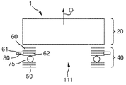
도 1은, 카메라 어셈블리의 개략적인 단면도이다.
도2 는, 카메라 어셈블리의 OIS 어셈블리의 사시도이다.
도 3은, 캔을 제거한 상태의 카메라 어셈블리의 사시도이다.
도 4는, 카메라 어셈블리의 연성 인쇄 회로 테이프의 사시도이다.
도 5는, 연성 인쇄 회로 테이프에 연결된 벤드 포머의 평면도이다.
도 6은, 연성 인쇄 회로 테이프에 연결된 벤드 포머의 사시도이다.
도 7은, 대안적인 벤드 포머의 사시도이다.
도 8은, 렌즈 어셈블리에서의 다른 형태의 연결과 함께, 캔을 제거한 카메라 어셈블리의 사시도이다.
도 9는, 크림프 플레이트 및 렌즈 어셈블리의 부분 단면도이다.
도 10은, 카메라 어셈블리의 비교 예(comparative example)의 개략적인 단면도이다.
도 11 및 12는, 도 10의 비교 예와 비교하여, 높이 감소를 달성한 카메라 어셈블리들의 개략적인 단면도이다.For a better understanding, embodiments of the present invention will be described by way of non-limiting example with reference to the accompanying drawings.
1 is a schematic cross-sectional view of a camera assembly.
Figure 2 is a perspective view of an OIS assembly of a camera assembly.
3 is a perspective view of the camera assembly with the can removed.
Figure 4 is a perspective view of a flexible printed circuit tape of a camera assembly.
Figure 5 is a plan view of a bender former connected to a flexible printed circuit tape.
Figure 6 is a perspective view of a bender former connected to a flexible printed circuit tape.
7 is a perspective view of an alternative bend former;
Figure 8 is a perspective view of a camera assembly with the can removed, with another type of connection in the lens assembly.
9 is a partial cross-sectional view of the crimp plate and lens assembly.
10 is a schematic cross-sectional view of a comparative example of a camera assembly.
Figures 11 and 12 are schematic cross-sectional views of camera assemblies that achieved height reduction compared to the comparative example of Figure 10.
도 1에는 광축(O, optical axis)을 따라 그려진 카메라 어셈블리(1)의 단면도가 도시된다. 이하에 설명되는 몇 가지 차이점들을 제외하고, 카메라 어셈블리(1)는 WO-2014/083318의 도 1 내지 10에 기술된 카메라 장치와 같은 구성을 갖고, 상기 특허는 본원에 참고로 포함된다. 간결함(brevity)을 위해, 카메라 어셈블리의 간결한 설명이 본 명세서에서 제공되지만, 보다 상세한 내용은 WO-2014/083318에 참조된다.1 is a cross-sectional view of a
카메라 어셈블리(1)은 OIS 어셈블리(40, optical image stabilisation assembly)에 의해 지지 구조물(4) 상에 지지된 렌즈 어셈블리(20)를 포함한다.The
지지 구조물(4)은 그 위에 마운트된(mount) 이미지 센서(6)를 지지한다. 지지 구조체(4)는 베이스(5)를 포함하고, 이미지 센서(6)는 베이스(5)의 전방 측부 상에 마운트된다. 베이스(5)의 후방 측부 상에는, IC(integrated circuit) 칩(30) 및 자이로스코프 센서(31)가 마운트된다. 지지 구조물(4)은 캡슐화 및 보호를 위해서, 카메라 어셈블리(1) 및 특히 OIS 어셈블리(40)를 수용(contain) 하는 캔(7)을 포함한다.The
렌즈 어셈블리(20)는 광학 축(O)를 따서 배열되는 2개의 렌즈들(22)을 지지하는 원통형 몸체의 형태인 렌즈 캐리지(21)를 포함하지만, 일반적으로 하나 이상의 임의의 개수의 렌즈들(22)이 제공될 수 있다. 카메라 어셈블리(1)는 렌즈(22)가 10mm 또는 그보다 작은 직경을 가진 소형 카메라(miniature camera)이다.The
렌즈 어셈블리(20)은 이미지를 이미지 센서(6) 상에 포커스 하도록 배열된다. 이미지 센서(6)는 이미지를 캡쳐하고, 예를 들어, CCD(charge-coupled device) 또는 CMOS(complimentary metal-oxide-semiconductor) 장치와 같은 임의의 적합한 유형일 수 있다.The
렌즈들(22)은 다음과 같은 방식으로 렌즈 캐리지(21)에 지지되어, 렌즈들(22)은 포커싱(focussing)을 제공하고 위해, 렌즈 캐리지(21)에 대해서 광축(O)을 따라 움직임이 가능하다.The
렌즈들(22)은 렌즈 홀더(23)에 고정되고, 렌즈 홀더(23)는 그 자체가 렌즈 홀더(23) 및 렌즈들(22)이 광축(O)에 따른 움직임을 허용하는 방식으로 렌즈 캐리지(21) 상에서 지지된다. 이 예에서, 모든 렌즈들(22)은 렌즈 홀더(23)에 고정된다. 하지만, 렌즈들(22)의 적어도 하나는 렌즈 홀더(23)에 고정된 상태로, 일반적으로 렌즈들(22)의 하나 이상은 렌즈 캐리지(21)에 고정될 수 있고, 렌즈 캐리지(21)에 대해 광축(O)을 따라서 움직임이 가능하지 않을 수 있다.The
렌즈 어셈블리(20)는 또한, 렌즈 캐리지(21) 및 렌즈 홀더(23) 사이에 제공되고, 렌즈 캐리지(21)에 대해 광축(O)을 따라 렌즈들(22) 및 렌즈 홀더(23)의 움직임을 구동하도록 배열되는 오토 포커스 액추에이터 장치(24)를 포함한다. 오토 포커스 액추에이터 장치(24)는 WO 2007/113478, WO-2008/099156 또는 WO-2009/056822(이들 각각은 본원에 참고 문헌으로 포함되며, 전체 설명을 위해 참고로 인용 됨) 중 어느 하나에 상세히 기술 된 바와 같이, 예를 들어, 보이스 코일 모터(voice coil motor, VCM) 또는 SMA 액추에이터 와이어들의 배열과 같은 임의의 적절한 유형일 수 있다. The
OIS 어셈블리(40)는 화살표(X, Y)로 도시된 바와 같이, 광축(O)에 수직한 평면에서 지지 구조물(4)에 대한 렌즈 어셈블리(20)의 움직임을 허용하는 방식으로, 렌즈 캐리지(21) 및 렌즈 어셈블리(20) 전체를 지지한다. 작동중인 OIS 어셈블리(40)는 그 평면 내에서 지지 구조물(4)에 대해 렌즈 어셈블리(20)를 움직이게 한다. 이러한 움직임은 이미지 센서(6) 상에 형성된 이미지가 이동되는 효과를 갖는다. 이것은, 예를 들어, 손 떨림(hand shake)에 의해 야기되는, 카메라 어셈블리(1)의 이미지 움직임을 보상하는 OIS를 제공하는데 사용된다. The
OIS어셈블리(40)의 구성은 도 2에 도시되고, 설명될 것이다. The configuration of the
OIS 어셈블리(40)는 렌즈 어셈블리(20), 특히 렌즈 캐리지(21)에 연결된 (a)이동 플랫폼(60, movable platform, 도 1에 개략적으로 도시되고, 아래에서 상세하게 설명 됨), 및 지지 구조물(4)의 일부를 구성하고, 베이스(5)에 연결된 (b)지지 플레이트(50)를 포함한다.The
이동 플랫폼(60)은 복수개의 볼들(75) 및 2개의 굴곡 암들(67, flexure arms)에 의해 지지 플레이트(50) 상에 지지된다. 지지 플레이트(50)는 각각의 볼들(75)이 위치되고, 축 방향으로 유지되는 리세스들(74, recesses)을 가진다. The moving
이 예에서, 3개의 볼들(75)이 제공된다. 하지만, 일반적으로 임의의 개수의 볼들(75)이 제공될 수 있다. 이동 가능한 플랫폼(60) 및 지지 플레이트(50)의 상대적인 틸팅(tilting)을 막기 위해, 적어도 3개의 볼들(75)이 제공되는 것이 바람직하다. 3개의 볼들(75)은 틸팅없이 지지 플레이트(50)를 지지하는데 충분하고, 3개의 볼들(75)의 제공은 공통 평면에서 각각의 볼(75)과 점 접촉을 유지하는데 필요한 공차를 완화시킨다는 장점을 갖는다. 3개 이상의 볼, 예를 들어, 대칭 설계를 허용할 수 있는 4개의 볼들(75)을 사용하는 것이 가능할 수 있다.In this example, three
볼들(75)은 광축(O)에 수직한 평면에서 지지 구조물(4)에 대해 카메라 렌즈 어셈블리(20)의 움직임을 허용하는 로터리 베어링들(rotary bearings)로서 동작한다. 볼들(75)은 구형 구 모양(spherical)일 수 있거나, 일반적으로, 이동 플랫폼(60) 및 지지 플레이트(50)를 지탱하고(bear against), 작동 중에, 전후로 구를 수(roll) 있는 곡면들을 갖는 임의의 로터리 요소일 수 있다.The
이동 플랫폼(60) 및 지지 플레이트(50)는 각각 절연체 레이어들(insulator layers) 및 접착제에 의해 접합된 금속 레이어들(metallic layers)의 적층 구조(laminated construction)를 갖는다. 절연체 레이어들은 각각 임의의 적절한 전기적 절연 재료로 만들어 질 수 있고, 예를 들어, 인쇄 회로에 일반적으로 사용되는 폴리이미드(polyimide) 소재인 캡톤(kapton)과 같은 폴리머 소재가 사용될 수 있다.The moving
접착제는 임의의 적합한 형태, 예를 들어, 접착제-함침된(adhesive-impregnated) 캡톤 또는 접합된 표면들 사이의 양면 접작체일 수 있다.The adhesive may be in any suitable form, e. G., An adhesive-impregnated capton or a double-sided adhesive between the bonded surfaces.
굴곡 암들(67)은 이동 플랫폼(60)과 지지 플레이트(50) 사이에서 각각 연장한다. 각각의 굴곡 암(67)은 굴곡 암(67)의 고정된 단(static end)에 베이스 피팅(68, base fitting)이 구비된다. 베이스 피팅(68)은 지지 플레이트(68) 및 지지 구조물(4)에 전체적으로 마운트된다. 이 마운트 하는 것은 납땜을 통해 달성될 수 있다.The flexing
각각의 굴곡 암(67)은 굴곡 암(67)의 이동 단(moving end)에서 이동 피팅(69, moving fitting)과 통합적으로 형성된다. 이동 피팅(69)은, 이동 플랫폼(60) 안에 적층 되고, 카메라 렌즈 어셈블리(20)에 마운트 되는 플레이트이다. 이동 피팅(69)은 지지 구조물(4) 및 카메라 렌즈 어셈블리(20) 사이에 배열되고, 로터리 베어링으로서 동작하는 볼들(75)을 지탱한다.Each
굴곡 암들(67)은 그것의 기계적 기능을 제공하기 위해 다음과 같이 배열된다. 각각의 굴곡 암(67)은 지지 구조물(4)과 카메라 렌즈 어셈블리(20)사이에 연결된 긴 빔(elongate beam)이다. The
굴곡 암들(67)은 그것들의 고유한 탄성으로 인해, 지지 구조물(4) 및 카메라 렌즈 어셈블리(20)를 볼들(75)에 대해 편향(bias)시키고, 편향 힘(biasing force)은 광축(O)에 평행하게 적용된다. 이것은 볼들(75)과의 접촉을 유지한다. 동시에, 굴곡 암(67)은 OIS 기능을 허용하도록, 광축(O)에 직교하는 지지 구조물(4)에 대한 카메라 렌즈 어셈블리(20)의 상기한 움직임을 허용하도록, 측 방향으로 꺾일(laterally deflected) 수 있다.The bending
굴곡 암들(67)은, 그것들의 고유의 탄성으로 인해, 카메라 렌즈 어셈블리(20)를 중심 위치(central position)를 향해 편향시키는 측 방향 편향 힘(lateral biasing force)을 제공한다. 결과적으로, 카메라 렌즈 어셈블리(20)의 측 방향 움직임의 구동이 없는 경우, 카메라 렌즈 어셈블리(20)는 구동이 없는 경우에도, 중앙 위치를 향하여 나아갈 것이다.The
굴곡 암들(67)은 광축(O)에 따른 볼들(75)에 적절한 유지 힘(retaining force)을 제공하고, 또한, 측 방향 편향 힘으로 측 방향 움직임을 허용하도록 다음과 같이 설계된다. 측 방향 편향 힘의 크기는 OIS를 방해하지 않을 정도로 충분히 낮게 유지되는 한편, 구동이 없는 경우, 카메라 렌즈 어셈블리(20)를 중심에 맞추기에 충분하다.The
각각의 굴곡 암(67)은 광축(O)을 직교하는 평균 폭이 광축(O)에 평행한 평균 두께보다 큰 단면을 갖는다. 각각의 굴곡 암(67)은 광축(O)의 주위에서 L-형상으로 연장하고, 일반적으로, 각의 크기(angular extent)는 굴곡 암(67)의 단들 사이에서 측정될 때, 적어도 90도인 것이 바람직하다.Each of the
OIS 어셈블리(40)의 제조된 상태에서, 굴곡 암들(67)은 지지 구조물(4) 및 카메라 렌즈 어셈블리(20)를 볼들(75)에 대해 편향시키는 프리-로링(pre-loading) 힘을 제공하기 위해 이완된 상태(relaxed state)로부터 꺾인다(deflected). In the manufactured state of the
굴곡 암들(67)은 좋은 베어링을 제공하고, 원하는 기계적 성질을 제공하며, 전기적으로 전도성인 적절한 소재로 만들어 진다. 보통, 소재는 상대적으로 높은 항복(yield)을 가진, 예를 들어 스테인리스 강(stainless steel)과 같은 강(steel)이다. The
OIS 어셈블리(40)는 추가적으로 지지 구조물(4)의 일부를 형성하는 지지 플레이트(50) 및 렌즈 어셈블리(20)에 연결된 이동 가능한 플랫폼(60)사이에서 연장하는 총 4개의 SMA 액추에이터 와이어들(80)을 포함한다.The
SMA 액추에이터 와이어들(80)은 일단이 지지 플레이트(50)에 적층 레이어들 중 하나인 레이어(52)에 형성된 크림프 부분들(51)에 의해 지지 플레이트(50)에 연결된다.The
SMA 액추에이터 와이어들(80)은 다른 단이 크림프 플레이트(62)에 형성된 크림프 부분들(61)에 의해 이동 플랫폼(60)에 연결된다. 크림프 플레이트(60)는 이동 플랫폼(60)의 적층 된 레이어들 중 하나이므로 렌즈 어셈블리(20)에 연결된다. 아래에서 자세하게 논의되는 이유로 인해서, 크림프 부분들(61)은 크림프 플레이트의 평면으로부터 렌즈 어셈블리(20)를 향한 방향으로 연장하는 형상을 갖는다. 크림프 플레이트(62)는 크림프 부분들(61)을 렌즈 어셈블리(20)을 향한 방향으로 크림프 플레이트(62)의 평면 상에 위치시키도록 단차들(64, steps)로 형성된다.The
크림프 플레이트(62)는 평면 내에서 연장한다. 그 유연성을 감소시키기 위해, 크림프 플레이트(62)는 크림프 플레이트(62)의 평면 밖으로 연장하는 복수개의 피쳐들(63, 일반적으로 하나 이상의 임의의 수의 그러한 피쳐가 제공될 수 있다.)이 제공된다. 이 경우, 피쳐들(63)은 크림프 플레이트(62)의 평면 밖으로 구부러진 탭이지만, 일반적으로, 피쳐들(63)은 다른 형태들을 가질 수 있다. 피쳐들(63)은 제조 동안, 접착제의 도포(application) 및 정렬(alignment)에 사용될 수 있다.The
크림프 플레이트(62)의 감소된 유연성은 상당한 이점을 제공한다. 왜냐하면, 감소된 유연성은, OIS 어셈블리의 설계가 개선될 수 있도록 허용하면서, 제조 동안, 처리를 허용하도록 요구되는 강성의 양을 여전히 제공한다. 예를 들어, 크림프 플레이트(62)와 같은 이동 플랫폼(60) 및 굴곡 암들(67)과 통합적으로 형성된 이동 피팅(69)의 구성 요소들은 다른 것들보다 얇게 만들어질 수 있다. 이와 유사하게, 이동 플랫폼(60)은, 다른 것보다 적은 수의 적층 된 구성 요소들에 의해 형성될 수 있다. 예를 들어, WO-2014/083318에는, 이동 플레이트가 인터페이스 플레이트를 가지고, 본 카메라 어셈블리(1)가 생략될 수 있는 구성이 개시되어 있다. 이것은 광축(O)에 따른 방향의 카메라 장치(1)의 높이 및 복잡도의 감소를 허용한다.The reduced flexibility of the
크림프 부분들(51, 61)은 SMA 액추에이터 와이어들(80)을 크림프 하여 기계적으로 그것들을 유지하고, 선택적으로 접착제의 사용에 의해 강화된다.Crimp
각각의 SMA 액추에이터 와이어들(80)은 인장 상태로 유지되어, 광축(O)에 수직한 방향으로 지지 플레이트(50) 및 이동 플랫폼(60) 사이에 힘을 적용한다.Each
SMA 액추에이터 와이어들(80)은 다음과 같이, 광축(O)의 주위의 배열을 갖는다. 각각의 SMA 액추에이터 와이어들(80)은, 대칭적인 배열(symmetrical arrangement)로 렌즈 어셈블리(20)의 일 측부를 따라 배열된다. 인접한 측부들 상의 SMA 액추에이터 와이어들(80)의 각각의 쌍을 고려하면, 인접한 단들(adjacent ends)에서, SMA 액추에이터 와이어들(80)은 도 2에 도시된 바와 같이, 지지 플레이트(50) 또는 이동 플랫폼(60)에 둘 다 연결된다. 예를 들어, 도 2의 SMA 액추에이터 와이어들(80)의 가장 밑의 쌍(lowermost pair)은 그것들의 인접한 단들에서 지지 플레이트(50)에 부착되고, 도 2의 SMA 액추에이터 와이어들(80)의 가장 왼쪽의 쌍(leftmost pair)은 그것들의 인접한 단들에서 이동 플레이트(60)에 부착된다. 결과적으로, 광축(O)에 수직한 평면 내의 임의의 방향으로의 움직임은, SMA 액추에이터 와이어들(80)의 조합의 작동(actuation)에 의해 구동될 수 있다. 인접한 측부들(adjacent sides) 상의 SMA 액추에이터 와이어들(80)의 임의의 쌍의 작동은, SMA 액추에이터 와이어들(80)의 이등분하는 방향으로 지지 플랫폼(60)에 대해 이동 플랫폼(60)을 이동시킬 것이다. 예를 들어, 도 2의 SMA 액추에이터 와이어들(80)의 가장 밑의 쌍의 수축(contraction)은 도 2의 이등분하는 방향들(X, Y) 방향으로의 움직임을 구동할 것이다. 임의의 방향으로의 움직임은 SMA 액추에이터 와이어들(80)의 작동(actuation)에 의해 달성될 수 있다. The
결과적으로, 광축(O)에 수직한 평면에서의 움직임의 범위 내의 임의의 위치로 SMA 액추에이터 와이어들(80)은 지지 어셈블리(4)에 대해 렌즈 어셈블리(20)를 움직이도록 선택적으로 구동될 수 있다. 움직임의 범위의 크기는 정상 동작 파라미터들 내에서의 SMA 액추에이터 와이어들(80)의 수축의 범위 및 기하학적 구조(geometry)에 의존한다. As a result, the
광축(O)에 수직한 지지 어셈블리(4)에 대한 렌즈 어셈블리(20)의 위치는 SMA 액추에이터 와이어들(80)의 온도를 선택적으로 변화시킴으로써 제어된다. 이것은 저항 가열(resistive heating)을 제공하는 선택적인 구동 전류들(drive current)이 SMA 액추에이터 와이어들(80)을 통과함으로써 달성된다. 가열(heating)은 구동 전류들에 의해 직접적으로 제공된다. 냉각(cooling)은 SMA 액추에이터 와이어들(80)이 그 주변에서 전도, 대류 및 복사에 의해 냉각되는 것을 허용하도록 구동 전류들을 감소시키거나 중단시킴으로써 제공된다. SMA 액추에이터 와이어들(80)의 신속한(rapid) 가열 및 냉각은 보통 수 헤르츠(Hertz)만큼의 주파수에서 발생하는 손 떨림을 보상하기 위해 필요하다. 포커스 및 줌 응용들(applications)에 있어서도, 신속한 반응이 필요하다. 이러한 이유로, SMA 액추에이터 와이어들(80)은, 보통 25μm의 직경을 갖는 비교적 얇다. 그러한 얇은 와이어는 매우 빠르게 가열 및 냉각하기 때문이다.The position of the
카메라 어셈블리(1)의 SMA 액추에이터 와이어들(80)의 제어는 IC 칩(30)에 구현되고, 각각의 SMA 액추에이터 와이어들(80)에 연결된 제어 회로에 의해 이루어진다. 제어 회로는 구동 신호들을 생성하여 OIS를 달성하고, 그것들을 SMA 액추에이터 와이어들(80)에 공급한다. 구동 신호들은 렌즈 어셈블리(20)의 각속도를 검출(detect)하는 자이로스코프 센서(31)의 출력 신호에 기초하여 생성되어, 카메라 어셈블리(1)의 진동을 검출하는 진동 센서로서 동작한다 상세한 설명을 위해 참조된WO-2014/083318에 기술된 바와 같이, 제어가 수행될 수 있다.The control of the
IC 칩(30)에 구현된 제어 회로는 또한, 도 3 및 도 4에 도시된 바와 같이, 렌즈 어셈블리(20) 및 지지 구조물(4) 사이에서 물리적으로 연결된 연성 인쇄 회로(FPC) 테이프(103)를 통해 전기적으로 AF 액추에이터 장치(24)에 연결되고, 다음과 같이 배열된다.The control circuit embodied in the
지지 구조물(4)는 방향(X)을 가로 질러 연장하는 카메라 어셈블리(1)의 제 1 측부 상의 베이스(5)를 따라 배열되는 입력 전도성 탭들(102, input conductive taps)을 갖는다. IC 칩(30)에 구현된 제어 회로로부터의 제어 신호들 및 외부 전원으로부터의 전력은 입력 전도성 탭들(102)에 공급된다. 유사하게, 렌즈 어셈블리(20)에 고정된 이동 플랫폼(60)은 제 1 측부에 인접하고, 방향(Y)를 가로 질러 연장하는 카메라 어셈블리(1)의 제 2 측부 상에 배열된 출력 전도성 탭들(104)를 갖는다.The
FPC 테이프(103)는 입력 및 출력 전도성 탭들(102, 104) 사이에 물리적 및 전기적으로 연결된다. 이 예에서, FPC 테이프는 입력 및 출력 전도성 탭들(102, 104) 사이에서 4개의 개별적인 전기적 연결들을 제공하지만, 일반적으로 임의의 수의 연결들을 제공할 수 있다. 출력 전도성 탭들(104)은 AF 액추에이터 장치(24)에 제어 신호들 및 전력을 공급하기 위해 AF 액추에이터 장치(24)에 연결된다. 선택적으로, 센서 신호들은 AF 액추에이터 장치(24)로부터 IC 칩(30) 내에 구현된 제어 회로로 FPC 테이프(103) 상의 전기적 연결들을 통해서 반대 방향으로 공급될 수 있다.The
FPC 테이프(103)는, 예를 들어, 폴리이미드, PEEK 또는 폴리에스테르(polyester)와 같은 플라스틱과 같은 적절한 소재로 만들어진 연성 기판(substrate)를 포함하는 종래의 구조(conventional construction)를 가질 수 있다.The
FPC 테이프(103)는 입력 전도성 탭들(102)로부터 제 1 측부를 따라서 연장하고, 제 2 측부를 따라 출력 전도성 탭들(104)로 연장하기 전에 코너(105) 주위에서 구부러진다.The
연성 인쇄 회로 테이프가 코너(105) 주위에서 구부러짐으로써, 광축(O)에 수직한 평면 내의 임의의 방향으로 지지 구조물(4)에 대한 렌즈 어셈블리(20)의 운동을 수용한다. FPC 테이프는 그것의 표면을 가로지거나 그것의 길이에 따른 다른 방향들로의 운동을 저항하는 동안, 보통 그것의 표면에 수직한 단일 방향으로 휘어질 것이다. 그러나 FPC 테이프(103)가 구부러지면, 코너(105)의 각각의 측부 상의 FPC 테이프(130)의 두 부분들은 최소한의 변형으로 다른 방향들로의 운동을 수용할 수 있다. 즉, 제 1 측부 상의 FPC 테이프(103)의 부분은 방향(X)으로의 렌즈 어셈블리(20)의 운동을 수용할 수 있고, 제 2 측부 상의 FPC 테이프(103)의 부분은 방향(Y)으로의 렌즈 어셈블리(20)의 운동을 수용할 수 있다.The flexible printed circuit tape bends around the
이 예에서, 코너(105)는 90도이고, 광축(O)에 평행한 축을 따라 연장한다. 이것은 코너 주위에서 구부러진 다른 구성들이 유사한 효과들을 제공할 수 있지만, 광축(O)에 수직한 평면에서 지지 구조물(4)에 대한 렌즈 어셈블리(20)의 운동의 최상의 조절(best accommodation)을 제공하기 때문에, 유리하다.In this example, the
선택적으로, FPC 테이프(103)는, 비록 벤드 포머(106)는 도 3에 도시되지 않지만, 도 4 내지 도 6에 도시된 벤드 포머(106)에 연결될 수 있다. 벤드 포머(106)은 코너(105)의 각각의 측부 상의 FPC 테이프(103)에 연결된다.Optionally, the
보다 구체적으로, 벤드 포머(106)는, 2개의 마운트 부분들(108) 및 브릿지 부분(109)를 포함하도록 형성된다. 도 6에서 가장 잘 도시된 바와 같이, 마운트 부분들(108)은, 코너(105)의 각각의 측부 상의 개별적인 위치들에서 FPC 테이프(103)와 연결된다. 브릿지 부분(109)은 FPC 테이프(103) 외부의 마운트 부분들(108) 사이에서 연장하고, FPC 테이프(103)완 연결되지 않고 연장한다.More specifically, the bender former 106 is formed to include two
도 7에 도시된 다른 형태에 있어서, 벤드 포머(106)는 FPC 테이프(103)의 맞은편 측부들 상의 FPC 테이프(103) 외부의 마운트 부분들(108) 사이에서 연장하는 2개의 브릿지 부분들(109)을 포함할 수 있다.7, the bend former 106 includes two bridge portions (not shown) extending between the
벤드 포머(106)은 FPC 테이프(103)의 굽힘을 제한(constrain)하고, 코너(105)를 정확하게 위치시킨다. 특히, 코너(105)는 FPC 테이프(103)를 소성 변형시킬 필요 없이 형성될 수 있다. 이것은 코너(105)에 의해 야기될 수 있는 FPC 테이프(103) 상의 변형을 감소시킨다. 유사하게, 벤드 포머(106)는 코너(105)의 각각의 측부 상의 FPC 테이프(103)의 2개의 부분들을 평평하게 유지하고, 테이프의 휘어짐(bowing), 캔(7)의 벽들과의 접촉 및 움직임의 방해를 방지한다.The bender former 106 constrain the bending of the
벤드 포머(106)는 예를 들어, 플라스틱과 같은 적절한 구조적 특성들을 제공하는 임의의 재료들이 일반적으로 사용될 수 있지만, 유리하게는 금속으로 형성될 수 있다.The bend former 106 may be advantageously formed of metal, although any material that provides suitable structural characteristics, such as, for example, plastic, may be commonly used.
벤드 포머(106)는 시트, 예를 들어, 금속 시트로 형성될 수 있다. 이 경우, 벤드 포머(106)는, 초기에 평면일 수 있고, FPC 테이프(130)에 연결 한 후에, 코너(105)에 평행한 축(107)을 따라, 브릿지 부분(109)을 소성 변형시킴으로써 형성될 수 있다. The bend former 106 may be formed of a sheet, for example, a metal sheet. In this case, the bender former 106 may initially be planar and, after connecting to the FPC tape 130, by plastically deforming the
도 3 및 도 4에서, 출력 전도성 탭들(104)은 이동 플랫폼(60) 상에 수평으로 놓인 것으로 도시된다. 보통, 출력 전도성 탭들(104)은 AF 액추에이터 장치(24)로의 연결을 용이하게 하기 위하여, OIS 어셈블리(40)의 상부 부분에 형성될 수 있다. 대안적으로 도 8에 도시된 바와 같이, FPC 테이프(103)은 렌즈 어셈블리(20)의 렌즈 캐리지(21)의 외부 표면에 제공되어 수직으로 놓이는 커스텀 탭들(110)에 연결하기 위한 커넥터 탭들(109)이 제공될 수 있다. 이 경우, 렌즈 어셈블리(20)는 FPC(103)의 커넥터 탭들(109)을 지탱할 수 있다. 제조 시, 커스텀 탭들(110)을 지탱하는 렌즈 어셈블리(20)는, FPC 테이프(103)을 지탱하는 OIS 어셈블리(40)에 부착되고, FPC(103)의 커넥터 탭들(109)은, 렌즈 어셈블리(20)상의 커스텀 탭들(110)에 연결된다.In Figures 3 and 4, the output conductive taps 104 are shown as lying horizontally on a moving
도 9에 도시된 바와 같이, 크림프 부분들(61)을 크림프 플레이트(62)의 평면(P) 위로, 렌즈 어셈블리(20)를 향하는 방향으로 위치시키기 위해 크림프 플레이트(62)가 단차들(64)로 형성되는 이유가 이제 논의될 것이다. 이는 OIS 어셈블리(40)의 부분이 광축(O)에 따른 방향으로 렌즈 어셈블리(20)와 오버랩 하도록, OIS 어셈블리(40)에 대해 렌즈 어셈블리(20)를 이동시킨 결과이고, OIS 어셈블리의 오버랩 된 부분은 SMA 액추에이터 와이어들(80)을 포함한다. 오버랩은 렌즈 홀더(23)와 렌즈 캐리지(21)와도 관련된다. 이러한 오버랩 배열은 WO-2014/083318에 개시된 카메라와 대조적이며, 여기서, 렌즈 어셈블리는 단순히 OIS 어셈블리 상에 쌓인다.9, the
여기에서, 광축(O)을 따르는 오버랩의 방향에 대한 언급은, 오버랩이 발생하는 방향, 즉, 광축(O)에 수직으로 보았을 때의 오버랩이라는 통상적인 의미를 갖는다. 결과적으로, 광축(O)에 따른 방향으로의 카메라 장치(1)의 높이가 감소될 수 있다. 이러한 높이의 감소는, 증가하는 소형화의 요구에 있어서, 매우 중요하다. 높이는, 특히, 장치의 두께를 줄이고자 하는 요구가 존재하는 스마트 폰과 같은 많은 전자 장치들에 있어서 중요하다. 높이의 감소는 광축(O)에 수직한 풋프린트(footprint)를 증가시키는 대신에 달성되지만, 높이를 감소시키는 것이 일반적으로 더 중요하다.Here, the reference to the direction of the overlap along the optical axis O has the usual meaning of overlap in the direction in which the overlap occurs, i.e., perpendicular to the optical axis O. As a result, the height of the
유사한 오버랩에 의해 유사한 높이 감소를 달성하는 카메라 어셈블리(1)에 대한 몇몇의 추가적인 대안적 구성들은, 이제 카메라 어셈블리(1)에 대한 대안적인 구조들을 도시하는 도 10 내지 12를 참조하여 설명 될 것이다. 후술되는 변경들을 제외하고, 각각의 대안적인 구성에 있어서, 카메라 어셈블리(1)는 전술한 것과 동일한 구성을 가지며, 공통 참조 번호는 공통 구성 요소에 대해 사용될 것이다. 특히, 도 10 내지 도 12는, 지지 플레이트(50), 이동 플랫폼(60), SMA 액추에이터 와이어들(80) 및 볼들(75)을 포함하는 OIS 어셈블리(40)을 도시한다. 지지 플레이트(50) 및 이동 플랫폼(60)은, SMA 액추에이터 와이어들(80)을 크림프하는 크림프 부분들(61)을 포함하는 복수개의 적층 된 레이어들을 포함하는 것으로 도시된다. 도 10 내지 도 12의 구성들에 있어서, 크림프 플레이트(62)는 단차들(64) 없이 형성되어, 크림프 부분들(61)은 크림프 플레이트(62)의 나머지의 평면상에 있다.Some additional alternative arrangements for the
도 10은 WO-2014/083318과 유사한 방식으로, 렌즈 어셈블리(20)가 OIS 어셈블리(40)상에 쌓여진 비교 예인 카메라 어셈블리(1)의 구성을 도시한다. 그 결과, OIS 어셈블리(40)은, 렌즈 어셈블리(20)과 오버랩 하지 않는다. 도 10은, 지지 플레이트(50) 및 이동 플랫폼(60)이 렌즈 어셈블리(20)로부터 광이 이미지 센서(도 10에 도시되지 않음)로 전송되는 조리개(111, aperture)를 둘러싸는 환형임을 도시한다. 크림프 플레이트(62) 및 SMA 액추에이터 와이어들(80)은 볼들(75)보다 지지 플레이트(50) 및 이동 플랫폼(60)의 적층 스택(laminate stack)을 위로 높게 한다(렌즈 어셈블리(20)을 향한 광축(O)을 따르는 방향으로).10 shows a configuration of a
도 11은, OIS 어셈블리(40)의 일부가 광축(O)을 따르는 방향으로 렌즈 어셈블리(20)를 오버랩 하는 카메라 어셈블리(1)의 구성을 도시한다. 이 경우, OIS 어셈블리(40)의 오버랩 된 부분은, SMA 액추에이터 와이어들(80) 및 이동 플랫폼(60)을 포함하지만, 볼들(75) 및 지지 플레이트(50)는 포함하지 않는다. 이러한 오버랩을 수용하기 위해, 이동 플랫폼(60)은 가장 상부의 레이어(uppermost layer)로서, 렌즈 어셈블리(20)가 마운트 되고, 렌즈 어셈블리(20)로부터 멀어지는 광축(O)을 따르는 방향으로 크래들(114, cradle)의 나머지로부터 오프셋 된 단차(115)를 갖는 크래들(114)을 포함한다. 도 11은, OIS 어셈블리(40) 및 렌즈 어셈블리(20)의 광축(O)에 따른 부분적인 오버랩을 도시한다. 이것은, 렌즈 어셈블리(20)의 바깥쪽의 이동 플랫폼(60)을 수용하기 위해 높이의 작은 감소 및 풋프린트의 약간의 증가를 제공한다.11 shows a configuration of a
도 12는, 볼들(75) 및 지지 플레이트(50)를 포함하는 OIS 어셈블리(40) 모두가, 광축(O)을 따르는 방향으로 렌즈 어셈블리(20)를 오버랩 하는 카메라 어셈블리(1)의 구성을 도시한다. 이 경우, OIS 어셈블리(40)는 거의 렌즈 어셈블리(20)의 바깥쪽에 있다. 도 11은, 광축(O)에 따른 OIS 어셈블리(40) 및 렌즈 어셈블리(20)의 전체 오버랩을 도시한다. 이러한 오버랩을 수용하기 위해서, 단차(115)가 크래들(114)의 나머지로부터 큰 오프셋을 제공한다는 점을 제외하고는, 이동 플랫폼(60)은 도 11과 유사한 구성의 크래들(114)를 포함한다. 볼들(75)은 보통 약 0.6mm로 측정되고, 이 경우, 약 1mm의 높이 감소가 달성될 수 있으므로, 이 구조는 매우 현저한 높이 절감(height saving)을 제공한다.Figure 12 shows the configuration of the
Claims (24)
지지 구조물;
렌즈 어셈블리; 및
광학 이미지 안정화 어셈블리를 포함하고,
상기 렌즈 어셈블리는,
렌즈 캐리지;
광축을 가지고, 상기 광축에 따른 렌즈의 움직임을 허용하는 방식으로 상기 렌즈 캐리지 상에 지지되는 적어도 하나의 렌즈 및
상기 광축을 따라 상기 렌즈 캐리지에 대해 렌즈를 움직이도록 배열된 오토포커스 액추에이터 장치를 포함하고,
상기 렌즈 캐리지는,
상기 광축에 수직인 평면에서 상기 지지 구조물에 대해 상기 렌즈 어셈블리의 움직임을 허용하는 방식으로 상기 지지 구조물 상에 지지되고,
상기 광학 이미지 안정화 어셈블리는,
상기 광축에 수직인 상기 평면에서 상기 지지 구조물에 대해 상기 렌즈 캐리지를 움직이도록 배열되고,
상기 카메라 어셈블리는 연성 인쇄 회로 테이프를 더 포함하고,
상기 연성 인쇄 회로 테이프는, 상기 지지 구조물 및 상기 렌즈 어셈블리 사이에 연결되고, 상기 오토 포커스 액추에이터 장치에 전기적 연결을 제공하고, 코너 주위에서 구부러지는 카메라 어셈블리.
In a camera assembly,
Support structure;
Lens assembly; And
An optical image stabilization assembly,
The lens assembly includes:
Lens carriage;
At least one lens having an optical axis and supported on the lens carriage in a manner that allows movement of the lens along the optical axis,
And an autofocus actuator arrangement arranged to move the lens relative to the lens carriage along the optical axis,
The lens carriage
Said support structure being supported on said support structure in a manner that allows movement of said lens assembly relative to said support structure in a plane perpendicular to said optical axis,
The optical image stabilization assembly includes:
And arranged to move the lens carriage relative to the support structure in the plane perpendicular to the optical axis,
Wherein the camera assembly further comprises a flexible printed circuit tape,
Wherein the flexible printed circuit tape is coupled between the support structure and the lens assembly and provides an electrical connection to the autofocus actuator device and bends around a corner.
상기 연성 인쇄 회로 테이프는,
90도로 코너 주위에서 구부러진 카메라 어셈블리.
The method according to claim 1,
The flexible printed circuit tape,
90 A camera assembly bent around a road corner.
상기 연성 인쇄 회로 테이프는,
상기 광축에 평행한 축을 따라 연장하는 코너 주위에서 구부러진 카메라 어셈블리.
3. The method according to claim 1 or 2,
The flexible printed circuit tape,
Wherein the camera assembly is bent around a corner extending along an axis parallel to the optical axis.
상기 코너의 각각의 측부 상의 상기 연성 인쇄 회로 테이프에 연결된 벤드 포머를 더 포함하는 카메라 어셈블리.
4. The method according to any one of claims 1 to 3,
Further comprising a bender former connected to the flexible printed circuit tape on each side of the corner.
상기 벤드 포머는, 금속으로 만들어진 카메라 어셈블리.
5. The method according to any one of claims 1 to 4,
The bender former is a metal-made camera assembly.
상기 벤드 포머는,
상기 코너의 각각의 측부 상에 분리된 위치들에서 상기 연성 인쇄 회로 테이프에 연결된 2개의 마운트 부분들 및
상기 연성 인쇄 회로 테이프에 연결되지 않고, 상기 마운트 부분들 사이에서 연장하는 적어도 하나의 브릿지 부분을 포함하는 카메라 어셈블리.
6. The method of claim 5,
The above-
Two mount portions connected to the flexible printed circuit tape at separate locations on each side of the corner,
And at least one bridge portion extending between the mount portions and not connected to the flexible printed circuit tape.
상기 적어도 하나의 브릿지 부분은, 상기 연성 인쇄 회로 테이프의 외부에 상기 마운트 부분들 사이에서 연장하는 카메라 어셈블리.
The method according to claim 6,
Wherein the at least one bridge portion extends between the mounting portions on the exterior of the flexible printed circuit tape.
상기 적어도 하나의 브릿지 부분은,
상기 연성 인쇄 회로 테이프의 반대쪽 측부들 상의 상기 연성 인쇄 회로 테이프의 외부에 상기 마운트 부분들 사이에서 연장하는 2개의 브릿지 부분들을 포함하는 카메라 어셈블리.
8. The method of claim 7,
Wherein the at least one bridge portion comprises:
And two bridge portions extending between the mount portions on the exterior of the flexible printed circuit tape on opposite sides of the flexible printed circuit tape.
상기 벤드 포머는, 상기 브릿지 부분이 소성 변형된 시트로부터 형성되는 카메라 어셈블리.
9. The method according to any one of claims 6 to 8,
Wherein the bend former is formed from a sheet that is plastically deformed.
상기 광학 이미지 안정화 어셈블리는, 형상 기억 합금 와이어들을 포함하는 카메라 어셈블리.
10. The method according to any one of claims 1 to 9,
Wherein the optical image stabilization assembly comprises shape memory alloy wires.
상기 지지 구조물에 마운트된 이미지 센서를 더 포함하는 카메라 어셈블리.
11. The method according to any one of claims 1 to 10,
Further comprising an image sensor mounted on the support structure.
상기 적어도 하나의 렌즈는 10mm 또는 그 보다 작은 직경을 가지는 카메라 어셈블리.
12. The method according to any one of claims 1 to 11,
Wherein the at least one lens has a diameter of 10 mm or less.
렌즈 어셈블리; 및
광학 이미지 안정화 어셈블리를 포함하고,
상기 렌즈 어셈블리는,
렌즈 캐리지;
광축을 가지고, 상기 광축에 따른 렌즈의 움직임을 허용하는 방식으로 상기 렌즈 캐리지 상에 지지되는 적어도 하나의 렌즈 및
상기 광축을 따라 상기 렌즈 캐리지에 대해 렌즈를 이동시키도록 배열된 오토포커스 액추에이터 장치를 포함하고,
상기 렌즈 캐리지는 상기 광축에 수직인 평면에서 상기 지지 구조물에 대해 상기 렌즈 어셈블리의 움직임을 허용하는 방식으로 상기 지지 구조물 상에 지지되고,
상기 광학 이미지 안정화 어셈블리는,
상기 광축에 수직인 상기 평면에서 상기 지지 구조물에 대해 상기 렌즈 캐리지를 움직이도록 배열되는 형상 기억 합금 와이어들을 포함하고,
상기 광학 이미지 안정화 어셈블리는,
상기 형상 기억 합금 와이어들의 일단을 크림프하는 상기 렌즈 어셈블리에 연결된 크림프 플레이트를 포함하고,
상기 크림프 플레이트는 평면 내에서 연장하고, 상기 크림프 플레이트의 유연성을 감소시키기 위해, 상기 크림프 플레이트의 상기 평면 밖으로 연장하는 적어도 하나의 피쳐가 제공되는 카메라 어셈블리.
Support structure;
Lens assembly; And
An optical image stabilization assembly,
The lens assembly includes:
Lens carriage;
At least one lens having an optical axis and supported on the lens carriage in a manner that allows movement of the lens along the optical axis,
And an autofocus actuator arrangement arranged to move the lens relative to the lens carriage along the optical axis,
The lens carriage being supported on the support structure in a manner that allows movement of the lens assembly relative to the support structure in a plane perpendicular to the optical axis,
The optical image stabilization assembly includes:
Wherein the shape memory alloy wires are arranged to move the lens carriage relative to the support structure in the plane perpendicular to the optical axis,
The optical image stabilization assembly includes:
And a crimp plate connected to the lens assembly for crimping one end of the shape memory alloy wires,
Wherein the crimp plate extends in a plane and wherein at least one feature extending out of the plane of the crimp plate is provided to reduce the flexibility of the crimp plate.
상기 적어도 하나의 피쳐는, 복수의 피쳐들을 포함하는 카메라 어셈블리.
14. The method of claim 13,
Wherein the at least one feature comprises a plurality of features.
상기 적어도 하나의 피쳐는, 상기 크림프 플레이트의 상기 평면 밖으로 구부러진 적어도 하나의 탭을 포함하는 카메라 어셈블리.
The method according to claim 13 or 14,
Wherein the at least one feature comprises at least one tab bent out of the plane of the crimp plate.
상기 지지 구조물에 마운트 되는 이미지 센서를 더 포함하는 카메라 어셈블리.
16. The method according to any one of claims 13 to 15,
Further comprising an image sensor mounted on the support structure.
상기 적어도 하나의 렌즈는, 10mm 또는 그 보다 작은 직경을 갖는 카메라 어셈블리.
17. The method according to any one of claims 13 to 16,
Wherein the at least one lens has a diameter of 10 mm or less.
렌즈 어셈블리; 및
광학 이미지 안정화 어셈블리를 포함하고,
상기 렌즈 어셈블리는,
렌즈 캐리지;
광축을 가지고, 상기 광축에 따른 렌즈의 움직임을 허용하는 방식으로 상기 렌즈 캐리지 상에 지지되는 적어도 하나의 렌즈 및
상기 광축을 따라 상기 렌즈 캐리지에 대해 렌즈를 움직이도록 배열된 오토포커스 액추에이터 장치를 포함하고,
상기 렌즈 캐리지는 상기 광축에 수직인 평면에서 상기 지지 구조물에 대해 상기 렌즈 어셈블리의 움직임을 허용하는 방식으로 상기 지지 구조물 상에 지지되고,
상기 광학 이미지 안정화 어셈블리는,
상기 광축에 수직인 상기 평면에서 상기 지지 구조물에 대해 상기 렌즈 캐리지를 움직이도록 배열되는 형상 기억 합금 와이어들을 포함하고,
상기 광학 이미지 안정화 어셈블리의 적어도 일 부분은, 상기 광축에 따른 방향으로 상기 렌즈 어셈블리를 오버랩 하는 카메라 어셈블리.
Support structure;
Lens assembly; And
An optical image stabilization assembly,
The lens assembly includes:
Lens carriage;
At least one lens having an optical axis and supported on the lens carriage in a manner that allows movement of the lens along the optical axis,
And an autofocus actuator arrangement arranged to move the lens relative to the lens carriage along the optical axis,
The lens carriage being supported on the support structure in a manner that allows movement of the lens assembly relative to the support structure in a plane perpendicular to the optical axis,
The optical image stabilization assembly includes:
Wherein the shape memory alloy wires are arranged to move the lens carriage relative to the support structure in the plane perpendicular to the optical axis,
Wherein at least a portion of the optical image stabilization assembly overlaps the lens assembly in a direction along the optical axis.
상기 렌즈 어셈블리를 오버랩 하는 상기 광학 이미지 안정화 어셈블리의 일 부분은, 상기 형상 기억 합금 와이어들을 포함하는 카메라 어셈블리.
19. The method of claim 18,
Wherein a portion of the optical image stabilization assembly that overlaps the lens assembly comprises the shape memory alloy wires.
상기 광학 이미지 안정화 어셈블리는, 상기 지지 구조물 및 상기 렌즈 어셈블리 사이에서 베어링 기능을 수행하도록 배열된 볼들을 포함하고,
상기 렌즈 어셈블리를 오버랩 하는 상기 광학 이미지 안정화 어셈블리의 일 부분은, 상기 볼들을 포함하는 카메라 어셈블리.
20. The method according to claim 18 or 19,
The optical image stabilization assembly comprising balls arranged to perform a bearing function between the support structure and the lens assembly,
Wherein a portion of the optical image stabilization assembly that overlaps the lens assembly comprises the balls.
상기 광학 이미지 안정화 어셈블리는,
상기 렌즈 어셈블리에 연결된 크림프 플레이트를 포함하고,
상기 크림프 플레이트는, 상기 형상 기억 합금 와어어들의 일단을 크림프하는 크림프 부분들을 포함하고,
상기 크림프 플레이트는, 평면 내에서 연장하고,
상기 크림프 플레이트는, 상기 렌즈 어셈블리를 향한 방향으로, 상기 크림프 플레이트의 상기 평면 위로 상기 크림프 부분들을 위치시키도록 형성되는 카메라 어셈블리.
21. The method according to any one of claims 18 to 20,
The optical image stabilization assembly includes:
And a crimp plate coupled to the lens assembly,
Wherein the crimp plate includes crimp portions for crimping one end of the shape memory alloy wire,
The crimp plate extends in a plane,
Wherein the crimp plate is configured to position the crimp portions over the plane of the crimp plate in a direction toward the lens assembly.
상기 광학 이미지 안정화 어셈블리는,
상기 형상 기억 합금 와이어들의 일단을 크림프하는 크림프 부분들을 포함하는 크림프 플레이트 및 크래들을 포함하는 이동 가능한 플랫폼을 포함하고,
상기 크래들은,
상기 렌즈 어셈블리가 연결되고, 상기 렌즈 어셈블리로부터 멀어지는 광축에 따른 방향으로 상기 크래들의 나머지로부터 오프셋 되는 단차를 가지는 카메라 어셈블리.
24. A method according to any one of claims 18 to 23
The optical image stabilization assembly includes:
And a movable platform including a cradle and a cradle including crimp portions for crimping one end of the shape memory alloy wires,
The cradle,
The lens assembly being connected and having a step offset from the rest of the cradle in a direction along an optical axis away from the lens assembly.
상기 지지 구조물에 마운트 되는 이미지 센서를 더 포함하는 카메라 어셈블리.
23. The method according to any one of claims 18 to 22,
Further comprising an image sensor mounted on the support structure.
상기 적어도 하나의 렌즈는, 10mm 또는 그보다 작은 직경을 갖는 카메라 어셈블리.24. The method according to any one of claims 18 to 23,
Wherein the at least one lens has a diameter of 10 mm or less.
Applications Claiming Priority (3)
| Application Number | Priority Date | Filing Date | Title |
|---|---|---|---|
| GB1412848.2 | 2014-07-18 | ||
| GBGB1412848.2A GB201412848D0 (en) | 2014-07-18 | 2014-07-18 | Suspension system for a camera lens element |
| PCT/GB2015/052043 WO2016009200A1 (en) | 2014-07-18 | 2015-07-15 | Camera assembly |
Publications (1)
| Publication Number | Publication Date |
|---|---|
| KR20170062441A true KR20170062441A (en) | 2017-06-07 |
Family
ID=51494846
Family Applications (1)
| Application Number | Title | Priority Date | Filing Date |
|---|---|---|---|
| KR1020177004461A Withdrawn KR20170062441A (en) | 2014-07-18 | 2015-07-15 | Camera assembly |
Country Status (7)
| Country | Link |
|---|---|
| US (3) | US10175499B2 (en) |
| EP (1) | EP3170048A1 (en) |
| JP (1) | JP2017522615A (en) |
| KR (1) | KR20170062441A (en) |
| CN (2) | CN111308830A (en) |
| GB (1) | GB201412848D0 (en) |
| WO (1) | WO2016009200A1 (en) |
Families Citing this family (63)
| Publication number | Priority date | Publication date | Assignee | Title |
|---|---|---|---|---|
| GB201412848D0 (en) | 2014-07-18 | 2014-09-03 | Cambridge Mechatronics Ltd | Suspension system for a camera lens element |
| US9366879B1 (en) | 2014-12-02 | 2016-06-14 | Hutchinson Technology Incorporated | Camera lens suspension with polymer bearings |
| US9454016B1 (en) | 2015-03-06 | 2016-09-27 | Hutchinson Technology Incorporated | Camera lens suspension with integrated electrical leads |
| US10840662B2 (en) | 2015-04-02 | 2020-11-17 | Hutchinson Technology Incorporated | Wire feeding and attaching system for camera lens suspensions |
| US11956544B2 (en) | 2016-03-11 | 2024-04-09 | Apple Inc. | Optical image stabilization with voice coil motor for moving image sensor |
| JP6710775B2 (en) | 2016-03-11 | 2020-06-17 | アップル インコーポレイテッドApple Inc. | Optical image stabilization with voice coil motor to move image sensor |
| CN107277304B (en) * | 2016-04-01 | 2020-11-20 | 台湾东电化股份有限公司 | Camera module and control method thereof |
| US10670878B2 (en) | 2016-05-19 | 2020-06-02 | Hutchinson Technology Incorporated | Camera lens suspensions |
| US11536930B2 (en) | 2016-05-24 | 2022-12-27 | Microsoft Licensing Technology, LLC. | Suspended actuator |
| JP6923563B2 (en) * | 2016-06-09 | 2021-08-18 | ハッチンソン テクノロジー インコーポレイテッドHutchinson Technology Incorporated | Shape memory alloy wire mounting structure with adhesive for suspension assembly |
| US10488186B2 (en) | 2016-06-29 | 2019-11-26 | Microsoft Technology Licensing, Llc | Alignment detection for split camera |
| US10542201B2 (en) | 2016-06-29 | 2020-01-21 | Microsoft Technology Licensing, Llc | Split-camera autoalignment |
| CN111522183B (en) * | 2016-07-29 | 2021-12-31 | 台湾东电化股份有限公司 | Lens driving device |
| CN107664895B (en) * | 2016-07-29 | 2020-06-09 | 台湾东电化股份有限公司 | Lens driving device |
| WO2018029458A1 (en) * | 2016-08-08 | 2018-02-15 | Cambridge Mechatronics Limited | Dual camera apparatus |
| US20180063438A1 (en) * | 2016-08-24 | 2018-03-01 | Hutchinson Technology Incorporated | Dual Camera Assemblies With Optical Image Stabilization |
| US10890734B1 (en) | 2017-03-29 | 2021-01-12 | Apple Inc. | Camera actuator for lens and sensor shifting |
| GB201707542D0 (en) * | 2017-05-11 | 2017-06-28 | Cambridge Mechatronics Ltd | Compact SMA shutter actuator |
| EP3625455A1 (en) * | 2017-05-17 | 2020-03-25 | Cambridge Mechatronics Limited | Electrical connections for sma actuators |
| US10863094B2 (en) * | 2017-07-17 | 2020-12-08 | Apple Inc. | Camera with image sensor shifting |
| JP2019029979A (en) * | 2017-08-04 | 2019-02-21 | ソニーセミコンダクタソリューションズ株式会社 | Semiconductor device, electronic apparatus, and manufacturing method |
| CN109782412B (en) * | 2017-11-15 | 2024-04-05 | 新思考电机有限公司 | Lens driving device, camera device and electronic equipment |
| US10809524B2 (en) | 2018-01-08 | 2020-10-20 | Facebook Technologies, Llc | Varifocal apparatuses, systems, and methods employing a deformable stepped lens |
| CN108174104A (en) * | 2018-01-31 | 2018-06-15 | 上海信迈电子科技有限公司 | Anti-shake structure, anti-shake system and camera device having the same |
| GB201820383D0 (en) * | 2018-12-14 | 2019-01-30 | Cambridge Mechatronics Ltd | Zero power hold SMA Actuator assembly |
| CN116774493A (en) | 2018-12-14 | 2023-09-19 | 三美电机株式会社 | Lens driving device, camera module, and camera mounting device |
| JP6739573B1 (en) * | 2019-03-29 | 2020-08-12 | エーエーシー コミュニケーション テクノロジーズ(ジョウシュウ)カンパニーリミテッド | Lens drive for camera |
| GB201904840D0 (en) * | 2019-04-05 | 2019-05-22 | Cambridge Mechatronics Ltd | A crimp and method for loading a wire therein |
| GB201907018D0 (en) | 2019-05-17 | 2019-07-03 | Cambridge Mechatronics Ltd | Actuator assembly |
| CN110727122A (en) * | 2019-09-11 | 2020-01-24 | 瑞声科技(新加坡)有限公司 | An optical anti-shake component |
| CN110750023A (en) * | 2019-09-11 | 2020-02-04 | 瑞声科技(新加坡)有限公司 | Lens module and electronic equipment |
| CN112752013B (en) * | 2019-10-30 | 2025-02-11 | 晋城三赢精密电子有限公司 | Anti-shake device, camera module and electronic device |
| CN110780508B (en) * | 2019-11-22 | 2025-04-11 | 河南皓泽电子股份有限公司昆山分公司 | SMA actuator, camera module and electronic device |
| CN115755426B (en) * | 2019-11-25 | 2025-07-25 | 新思考电机有限公司 | Optical component driving device, camera device, and electronic apparatus |
| GB2589385B (en) | 2019-12-01 | 2022-01-12 | Cambridge Mechatronics Ltd | Actuator assembly |
| CN112914532B (en) * | 2019-12-06 | 2025-02-18 | 研能科技股份有限公司 | Blood pressure measurement module |
| CN111158102B (en) * | 2019-12-30 | 2021-07-02 | 诚瑞光学(常州)股份有限公司 | Actuating device and method of controlling SMA actuator wire |
| US11388322B2 (en) | 2020-02-07 | 2022-07-12 | Samsung Electro-Mechanics Co., Ltd. | Camera module having rotatable lens module and frames and portable electronic device including the same |
| GB2592579A (en) | 2020-02-26 | 2021-09-08 | Cambridge Mechatronics Ltd | A camera assembly |
| GB2593681A (en) * | 2020-03-26 | 2021-10-06 | Cambridge Mechatronics Ltd | A shape memory actuator |
| CN111443498A (en) * | 2020-04-15 | 2020-07-24 | Oppo广东移动通信有限公司 | Lens modules and electronic equipment |
| US20230236474A1 (en) * | 2020-04-16 | 2023-07-27 | Cambridge Mechatronics Limited | Actuator assembly |
| GB2594921A (en) * | 2020-04-16 | 2021-11-17 | Cambridge Mechatronics Ltd | Actuator assembly |
| GB2594245A (en) * | 2020-04-16 | 2021-10-27 | Cambridge Mechatronics Ltd | Actuator assembly |
| CN113572918B (en) * | 2020-04-29 | 2022-10-14 | 宁波舜宇光电信息有限公司 | Periscopic continuous light-variable module and corresponding multi-camera module |
| TWI766450B (en) * | 2020-05-13 | 2022-06-01 | 大陸商廣州立景創新科技有限公司 | Imaging apparatus and method for assembling the same |
| CN111641761B (en) * | 2020-05-27 | 2022-04-29 | 维沃移动通信有限公司 | Camera module and electronic equipment |
| CN212211175U (en) * | 2020-06-23 | 2020-12-22 | 新思考电机有限公司 | OIS motor drive structure, OIS motor, camera device |
| WO2022014859A1 (en) * | 2020-07-13 | 2022-01-20 | 엘지이노텍 주식회사 | Lens driving device, camera module and optical device |
| US11743586B2 (en) * | 2020-07-13 | 2023-08-29 | Apple Inc. | Camera actuator with moving coils and dynamic flex circuit |
| CN114079712B (en) * | 2020-08-11 | 2022-09-27 | 宁波舜宇光电信息有限公司 | Anti-shake camera module and preparation method thereof |
| US11483461B2 (en) * | 2020-08-12 | 2022-10-25 | Apple Inc. | Techniques for forming suspension assemblies for a camera |
| GB202110839D0 (en) * | 2021-07-28 | 2021-09-08 | Cambridge Mechatronics Ltd | Actuator assembly |
| US11575835B2 (en) | 2020-09-24 | 2023-02-07 | Apple Inc. | Multi-axis image sensor shifting system |
| GB202019166D0 (en) * | 2020-12-04 | 2021-01-20 | Cambridge Mechatronics Ltd | Actuator assembly |
| GB2602627B (en) * | 2020-12-31 | 2023-06-07 | Cambridge Mechatronics Ltd | Actuator assemblies |
| CN114755795A (en) * | 2021-01-08 | 2022-07-15 | 台湾东电化股份有限公司 | Optical element driving mechanism |
| JP7611057B2 (en) * | 2021-02-09 | 2025-01-09 | ニデックインスツルメンツ株式会社 | Optical Unit |
| CN112987327B (en) * | 2021-03-03 | 2021-10-29 | 上海比路电子股份有限公司 | Anti-shake device for camera lens |
| EP4348325A1 (en) * | 2021-06-02 | 2024-04-10 | Cambridge Mechatronics Limited | Actuator arrangement |
| US12587744B2 (en) * | 2021-08-02 | 2026-03-24 | Cambridge Mechatronics Limited | Actuator assembly with bearing arrangement and electrical interconnector |
| GB202119163D0 (en) * | 2021-12-31 | 2022-02-16 | Cambridge Mechatronics Ltd | Actuator assembly |
| US20230280637A1 (en) * | 2022-05-31 | 2023-09-07 | Meta Platforms Technologies, Llc | Camera device with two-stage actuators and camera device packaging using sandwich molding technique |
Family Cites Families (29)
| Publication number | Priority date | Publication date | Assignee | Title |
|---|---|---|---|---|
| US2168911A (en) * | 1937-05-07 | 1939-08-08 | Pierre H Meyer | Corner bracket for shelves |
| JP4088416B2 (en) * | 1998-02-06 | 2008-05-21 | ファシリテック ユーエスエー インコーポレーテッド | Spill containment assembly |
| JP4441211B2 (en) * | 2003-08-13 | 2010-03-31 | シチズン電子株式会社 | Small imaging module |
| JP2006145704A (en) * | 2004-11-17 | 2006-06-08 | Olympus Corp | Lens barrel and electronic equipment |
| US7789547B2 (en) * | 2005-09-28 | 2010-09-07 | Cooper Technologies Company | LED-fiber optic combination for simulating neon lit signage |
| US7929848B2 (en) * | 2006-02-14 | 2011-04-19 | Nikon Corporation | Vibration detection device, optical device, and method of operation of vibration detection device |
| EP1999507B1 (en) | 2006-03-30 | 2011-09-07 | Cambridge Mechatronics Limited | Camera lens actuation apparatus |
| JP5044210B2 (en) * | 2006-12-28 | 2012-10-10 | 株式会社タムロン | Lens drive device |
| EP2261507A1 (en) | 2007-02-12 | 2010-12-15 | Cambridge Mechatronics Limited | Shape memory alloy actuation apparatus |
| WO2009056822A2 (en) | 2007-10-30 | 2009-05-07 | Cambridge Mechatronics Limited | Shape memory alloy actuation apparatus |
| KR100982266B1 (en) * | 2008-04-24 | 2010-09-14 | 삼성전기주식회사 | Lens drive module |
| WO2010012991A2 (en) * | 2008-07-30 | 2010-02-04 | Cambridge Mechatronics Limited | Shape memory alloy actuation apparatus |
| US8441749B2 (en) * | 2009-02-09 | 2013-05-14 | Cambridge Mechatronics Limited | Shape memory alloy actuation apparatus |
| CN101986192A (en) * | 2009-07-28 | 2011-03-16 | 株式会社腾龙 | Image stabilizing apparatus, lens apparatus, imaging apparatus, and correction optical apparatus |
| KR101770856B1 (en) * | 2010-02-26 | 2017-09-05 | 캠브리지 메카트로닉스 리미티드 | Sma actuation apparatus |
| WO2011146921A1 (en) * | 2010-05-21 | 2011-11-24 | Mladen Lijesnic | Connector for panel members |
| WO2012004994A1 (en) * | 2010-07-07 | 2012-01-12 | パナソニック株式会社 | Camera drive device |
| WO2012038703A2 (en) * | 2010-09-22 | 2012-03-29 | Cambridge Mechatronics Limited | Optical image stabilisation |
| TWI416240B (en) * | 2011-03-30 | 2013-11-21 | Largan Precision Co Ltd | Photographing module |
| KR101354775B1 (en) * | 2011-12-23 | 2014-01-22 | 삼성전기주식회사 | Camera module |
| US9518566B2 (en) * | 2012-05-25 | 2016-12-13 | Cambridge Mechatronics Limited | Shape memory alloy actuation apparatus |
| GB201221306D0 (en) | 2012-11-27 | 2013-01-09 | Cambridge Mechatronics Ltd | Suspension system for a camera lens element |
| KR102003043B1 (en) * | 2012-12-28 | 2019-07-23 | 삼성전자주식회사 | Flexible printed circuit board and small camera apparatus having the same |
| US9372352B2 (en) * | 2013-08-23 | 2016-06-21 | Samsung Electro-Mechanics Co., Ltd. | Lens driving device and camera module including the same |
| JP6138969B2 (en) * | 2014-01-10 | 2017-05-31 | シャープ株式会社 | The camera module |
| JP6255290B2 (en) * | 2014-03-27 | 2017-12-27 | 日本電産サンキョー株式会社 | Method for preventing resonance in optical unit with shake correction function, and optical unit with shake correction function |
| GB201412848D0 (en) * | 2014-07-18 | 2014-09-03 | Cambridge Mechatronics Ltd | Suspension system for a camera lens element |
| US9366879B1 (en) | 2014-12-02 | 2016-06-14 | Hutchinson Technology Incorporated | Camera lens suspension with polymer bearings |
| US9454016B1 (en) | 2015-03-06 | 2016-09-27 | Hutchinson Technology Incorporated | Camera lens suspension with integrated electrical leads |
-
2014
- 2014-07-18 GB GBGB1412848.2A patent/GB201412848D0/en not_active Ceased
-
2015
- 2015-07-15 CN CN201911354285.8A patent/CN111308830A/en active Pending
- 2015-07-15 JP JP2017522741A patent/JP2017522615A/en not_active Withdrawn
- 2015-07-15 CN CN201580044156.2A patent/CN107077044B/en active Active
- 2015-07-15 WO PCT/GB2015/052043 patent/WO2016009200A1/en not_active Ceased
- 2015-07-15 US US15/326,865 patent/US10175499B2/en active Active
- 2015-07-15 EP EP15741588.6A patent/EP3170048A1/en not_active Withdrawn
- 2015-07-15 KR KR1020177004461A patent/KR20170062441A/en not_active Withdrawn
-
2018
- 2018-11-20 US US16/196,959 patent/US11526021B2/en active Active
-
2022
- 2022-11-10 US US17/984,847 patent/US12596267B2/en active Active
Also Published As
| Publication number | Publication date |
|---|---|
| JP2017522615A (en) | 2017-08-10 |
| US11526021B2 (en) | 2022-12-13 |
| US10175499B2 (en) | 2019-01-08 |
| US20170219842A1 (en) | 2017-08-03 |
| US12596267B2 (en) | 2026-04-07 |
| CN111308830A (en) | 2020-06-19 |
| GB201412848D0 (en) | 2014-09-03 |
| CN107077044A (en) | 2017-08-18 |
| WO2016009200A1 (en) | 2016-01-21 |
| CN107077044B (en) | 2020-01-07 |
| US20190086686A1 (en) | 2019-03-21 |
| US20230071152A1 (en) | 2023-03-09 |
| EP3170048A1 (en) | 2017-05-24 |
Similar Documents
| Publication | Publication Date | Title |
|---|---|---|
| US12596267B2 (en) | Camera assembly | |
| US12422733B2 (en) | Shape memory alloy actuators and methods thereof | |
| US12049877B2 (en) | Shape memory alloy actuator | |
| US11782287B2 (en) | Shape memory alloy actuator bearings | |
| US11448853B2 (en) | Shape memory alloy actuators and methods thereof | |
| EP2926191B1 (en) | Suspension system for a camera lens element | |
| JP6966211B2 (en) | Camera module and how to control it | |
| US11686294B2 (en) | Shape memory alloy actuators and methods thereof | |
| CN103913931B (en) | Flexible printed circuit board and the small-sized photographic means for including it | |
| US20200033699A1 (en) | Camera module | |
| CN112654786A (en) | Shape memory alloy actuator and method thereof | |
| US12585137B2 (en) | Shape memory alloy actuator assembly | |
| US12276811B2 (en) | Sensor shifting actuator and camera module including sensor shifting actuator | |
| US20250097577A1 (en) | Actuator assembly | |
| WO2023126633A1 (en) | Actuator assembly | |
| WO2023126632A1 (en) | Actuator assembly |
Legal Events
| Date | Code | Title | Description |
|---|---|---|---|
| PA0105 | International application |
Patent event date: 20170217 Patent event code: PA01051R01D Comment text: International Patent Application |
|
| PG1501 | Laying open of application | ||
| PC1203 | Withdrawal of no request for examination |