KR20160070006A - Collision avoidance method, control device, and program - Google Patents
Collision avoidance method, control device, and program Download PDFInfo
- Publication number
- KR20160070006A KR20160070006A KR1020150172086A KR20150172086A KR20160070006A KR 20160070006 A KR20160070006 A KR 20160070006A KR 1020150172086 A KR1020150172086 A KR 1020150172086A KR 20150172086 A KR20150172086 A KR 20150172086A KR 20160070006 A KR20160070006 A KR 20160070006A
- Authority
- KR
- South Korea
- Prior art keywords
- arm
- interference
- cone
- robot arm
- range
- Prior art date
- Legal status (The legal status is an assumption and is not a legal conclusion. Google has not performed a legal analysis and makes no representation as to the accuracy of the status listed.)
- Ceased
Links
Images


Classifications
-
- B—PERFORMING OPERATIONS; TRANSPORTING
- B25—HAND TOOLS; PORTABLE POWER-DRIVEN TOOLS; MANIPULATORS
- B25J—MANIPULATORS; CHAMBERS PROVIDED WITH MANIPULATION DEVICES
- B25J9/00—Program-controlled manipulators
- B25J9/16—Program controls
- B25J9/1656—Program controls characterised by programming, planning systems for manipulators
-
- B—PERFORMING OPERATIONS; TRANSPORTING
- B25—HAND TOOLS; PORTABLE POWER-DRIVEN TOOLS; MANIPULATORS
- B25J—MANIPULATORS; CHAMBERS PROVIDED WITH MANIPULATION DEVICES
- B25J9/00—Program-controlled manipulators
- B25J9/16—Program controls
- B25J9/1615—Program controls characterised by special kind of manipulator, e.g. planar, scara, gantry, cantilever, space, closed chain, passive/active joints and tendon driven manipulators
- B25J9/1623—Parallel manipulator, Stewart platform, links are attached to a common base and to a common platform, plate which is moved parallel to the base
-
- B—PERFORMING OPERATIONS; TRANSPORTING
- B25—HAND TOOLS; PORTABLE POWER-DRIVEN TOOLS; MANIPULATORS
- B25J—MANIPULATORS; CHAMBERS PROVIDED WITH MANIPULATION DEVICES
- B25J9/00—Program-controlled manipulators
- B25J9/16—Program controls
- B25J9/1656—Program controls characterised by programming, planning systems for manipulators
- B25J9/1664—Program controls characterised by programming, planning systems for manipulators characterised by motion, path, trajectory planning
- B25J9/1666—Avoiding collision or forbidden zones
-
- B—PERFORMING OPERATIONS; TRANSPORTING
- B25—HAND TOOLS; PORTABLE POWER-DRIVEN TOOLS; MANIPULATORS
- B25J—MANIPULATORS; CHAMBERS PROVIDED WITH MANIPULATION DEVICES
- B25J9/00—Program-controlled manipulators
- B25J9/16—Program controls
- B25J9/1674—Program controls characterised by safety, monitoring, diagnostic
- B25J9/1676—Avoiding collision or forbidden zones
-
- G—PHYSICS
- G05—CONTROLLING; REGULATING
- G05B—CONTROL OR REGULATING SYSTEMS IN GENERAL; FUNCTIONAL ELEMENTS OF SUCH SYSTEMS; MONITORING OR TESTING ARRANGEMENTS FOR SUCH SYSTEMS OR ELEMENTS
- G05B2219/00—Program-control systems
- G05B2219/30—Nc systems
- G05B2219/39—Robotics, robotics to robotics hand
- G05B2219/39082—Collision, real time collision avoidance
-
- Y—GENERAL TAGGING OF NEW TECHNOLOGICAL DEVELOPMENTS; GENERAL TAGGING OF CROSS-SECTIONAL TECHNOLOGIES SPANNING OVER SEVERAL SECTIONS OF THE IPC; TECHNICAL SUBJECTS COVERED BY FORMER USPC CROSS-REFERENCE ART COLLECTIONS [XRACs] AND DIGESTS
- Y10—TECHNICAL SUBJECTS COVERED BY FORMER USPC
- Y10S—TECHNICAL SUBJECTS COVERED BY FORMER USPC CROSS-REFERENCE ART COLLECTIONS [XRACs] AND DIGESTS
- Y10S901/00—Robots
- Y10S901/02—Arm motion controller
Landscapes
- Engineering & Computer Science (AREA)
- Robotics (AREA)
- Mechanical Engineering (AREA)
- Health & Medical Sciences (AREA)
- General Health & Medical Sciences (AREA)
- Orthopedic Medicine & Surgery (AREA)
- Manipulator (AREA)
- Numerical Control (AREA)
Abstract
Description
본 발명은 간섭 회피 방법, 제어 장치 및 프로그램에 관한 것으로, 특히, 로봇 아암의 간섭을 회피하는 간섭 회피 방법, 제어 장치 및 프로그램에 관한 것이다. The present invention relates to an interference avoiding method, a control apparatus, and a program, and more particularly, to an interference avoiding method, a control apparatus, and a program that avoid interference of a robot arm.
복수의 관절을 갖는 로봇 아암의 동작을 제어해서 로봇 아암을 실시간으로 조작하는 방법으로서, 예를 들어, 마스터 슬레이브 방법이 있다. 마스터 슬레이브 방법에서는, 마스터측 장치(제어 장치)가 제어값을 지정하여, 그 지정된 제어값에 따라서, 슬레이브측 장치(로봇 아암)가 동작한다. 지정되는 제어값으로서 로봇 아암의 손끝 위치가 지정되는 경우, 역운동학 계산을 사용해서 각 관절의 관절 각도가 산출된다. For example, there is a master slave method as a method of controlling the robot arm having a plurality of joints in real time by controlling the operation of the robot arm. In the master slave method, the master side apparatus (control apparatus) designates a control value, and the slave side apparatus (robot arm) operates according to the designated control value. When the fingertip position of the robot arm is designated as the specified control value, the joint angle of each joint is calculated using the inverse kinematic calculation.
여기서, 로봇의 주위에는, 로봇의 몸통체 등의 장해물이 존재한다. 따라서, 손끝 위치를 지정하여 로봇 아암을 제어하는 경우, 각 관절의 관절 각도를 산출할 뿐만 아니라, 로봇 아암이 몸통체 등의 장해물과 간섭하지 않는 해(간섭 회피 해)를 산출할 필요가 있다. 그리고, 로봇 아암을 실시간으로 조작하는 경우, 상술한 관절 각도의 산출과 간섭 회피 해의 산출을, 실시간으로 행할 필요가 있다. Here, an obstacle such as a body of the robot exists around the robot. Therefore, when the robot arm is controlled by designating the fingertip position, it is necessary not only to calculate the joint angle of each joint but also to calculate a solution (interference avoidance solution) in which the robot arm does not interfere with the obstacle such as the body. When the robot arm is operated in real time, it is necessary to calculate the above-described joint angle and calculate the interference avoidance solution in real time.
상기 기술에 관련하여, 일본 특허 공개 제2011-093015호 공보에는, 로봇 아암의 손끝부의 핸드 아이 센서의 존재를 고려한 주변과의 간섭 방지를 도모하는, 핸드 아이식 빈피킹 로봇의 제어 장치가 개시되어 있다. 일본 특허 공개 제2011-093015호 공보에 관한 제어 장치는, 간섭 패턴 테이블을 기억하는 테이블 기억 수단과, 상기 핸드 아이 센서와 상기 로봇 아암이 간섭하는지 여부를 판정하는 이동처 간섭 판정 수단과, 자세 재결정 수단을 갖는다. Japanese Patent Laid-Open Publication No. 2011-093015 discloses a control apparatus for a hand-eye free-picking robot that prevents interference with the surroundings in consideration of the presence of a hand-eye sensor at the fingertip of the robot arm have. Japanese Patent Laid-Open Publication No. 2011-093015 discloses a control apparatus comprising table storage means for storing an interference pattern table, movement destination interference determination means for determining whether the hand eye sensor and the robot arm are in interference, .
여기서, 간섭 패턴 테이블은, 로봇 아암의 각 자유축에 있어서의 회전 각도의, 상기 핸드 아이 센서와 상기 로봇 아암이 간섭하는 조합 패턴을 정의한다. 또한, 이동처 간섭 판정 수단은, 엔드 이펙터가 워크의 위치에 있어서 결정한 자세가 되도록 상기 로봇 아암을 구동시킨 경우의, 상기 각 자유축에 있어서의 회전 각도의 조합 패턴과, 상기 간섭 패턴 테이블에 있어서 정의된 조합 패턴과의 대조에 기초하여, 핸드 아이 센서와 상기 로봇 아암이 간섭하는지 여부를 판정한다. 자세 재결정 수단은, 간섭한다고 판정된 경우에, 상기 워크의 피킹에 적합한 상기 엔드 이펙터의 자세를 새롭게 결정한다.Here, the interference pattern table defines a combination pattern in which the hand-eye sensor and the robot arm interfere with each other with respect to the rotation angle of each free axis of the robot arm. It is preferable that the movement destination interference determining means determines whether or not the combination pattern of the rotational angles of the respective free shafts in the case where the robot arm is driven so that the end effector is in a determined attitude at the position of the work, Eye sensor and the robot arm based on a comparison with the defined combination pattern. The posture recrystallization means newly determines the posture of the end effector suitable for picking the workpiece when it is judged that the workpiece interferes.
일본 특허 공개 제2011-093015호 공보에 관한 기술에서는, 사전에 간섭 패턴 테이블을 준비해 둘 필요가 있다. 이 패턴 테이블을 준비하기 위해, 방대한 시간을 필요로 할 우려가 있다. 따라서, 일본 특허 공개 제2011-093015호 공보에 관한 기술을 사용해도, 간섭 회피 해를 실시간으로 산출하는 것은 곤란하다. In the technique related to Japanese Patent Laid-Open Publication No. 2011-093015, it is necessary to prepare an interference pattern table in advance. In order to prepare this pattern table, there is a concern that it takes a lot of time. Therefore, it is difficult to calculate the interference avoidance solution in real time even using the technique disclosed in Japanese Patent Laid-Open Publication No. 2011-093015.
본 발명은, 이와 같은 과제를 해결하기 위해 이루어진 것이며, 로봇 아암의 간섭을 회피하기 위한 계산을 고속으로 행하는 것이 가능한 간섭 회피 방법, 제어 장치 및 프로그램을 제공하는 데 있다.An object of the present invention is to provide an interference avoiding method, a control apparatus, and a program that can perform calculation for avoiding interference of a robot arm at a high speed.
본 발명에 관한 간섭 회피 방법은, 관절부를 통하여 제1 아암과 제2 아암이 접속되어 구성된 로봇 아암의 장해물에 대한 간섭을 회피하는 로봇 아암의 간섭 회피 방법이며, 상기 로봇 아암의 양단부의 위치가 고정된 상태에 있어서의, 상기 제1 아암 및 상기 제2 아암의 가동 영역을 산출하고, 상기 가동 영역과, 상기 장해물을 포함하는 장해물 영역의 경계면 상의 제1 선과의 교점을 산출하고, 상기 산출된 교점에 기초하여, 상기 가동 영역에서 상기 로봇 아암이 상기 장해물 영역에 간섭하지 않는 간섭 회피 범위를 결정한다. An interference avoiding method according to the present invention is a interference avoiding method for a robot arm that avoids interference with an obstacle of a robot arm constituted by connecting a first arm and a second arm via a joint portion, wherein the position of both ends of the robot arm is fixed Calculating an intersection point between the movable area and the first line on the boundary surface between the obstacle area including the obstacle and the calculated intersection point between the movable area and the obstacle area, , The interference avoiding range in which the robot arm does not interfere with the obstacle area in the movable area is determined.
또한, 본 발명에 관한 제어 장치는, 관절부를 통하여 제1 아암과 제2 아암이 접속되어 구성된 로봇 아암을 제어하는 제어 장치이며, 상기 로봇 아암의 양단부의 위치가 고정된 상태에 있어서의, 상기 제1 아암 및 상기 제2 아암의 가동 영역을 산출하는 가동 영역 산출 수단과, 상기 가동 영역과, 장해물을 포함하는 장해물 영역의 경계면 상의 제1 선과의 교점을 산출하는 교점 산출 수단과, 상기 산출된 교점에 기초하여, 상기 가동 영역에서 상기 로봇 아암이 상기 장해물 영역에 간섭하지 않는 간섭 회피 범위를 결정하는 간섭 회피 범위 결정 수단을 갖는다. A control device according to the present invention is a control device for controlling a robot arm constituted by connecting a first arm and a second arm via a joint part, wherein the control device is a control device in which the positions of both ends of the robot arm are fixed, An intersection computing means for computing an intersection between the movable area and a first line on an interface between an obstacle area including an obstacle and a first line; And an interference avoiding range determining unit that determines an interference avoiding range in which the robot arm does not interfere with the obstacle area in the movable area.
또한, 본 발명에 관한 프로그램은, 관절부를 통하여 제1 아암과 제2 아암이 접속되어 구성된 로봇 아암의 장해물에 대한 간섭을 회피하는 로봇 아암의 간섭 회피 방법을 실현하는 프로그램이며, 상기 로봇 아암의 양단부의 위치가 고정된 상태에 있어서의, 상기 제1 아암 및 상기 제2 아암의 가동 영역을 산출하는 스텝과, 상기 가동 영역과, 상기 장해물을 포함하는 장해물 영역의 경계면 상의 제1 선과의 교점을 산출하는 스텝과, 상기 산출된 교점에 기초하여, 상기 가동 영역에서 상기 로봇 아암이 상기 장해물 영역에 간섭하지 않는 간섭 회피 범위를 결정하는 스텝을 컴퓨터에 실행시킨다. The program according to the present invention is a program for realizing an interference avoiding method of a robot arm that avoids interference with an obstacle of a robot arm constituted by connecting a first arm and a second arm via a joint portion, Calculating an intersection point between the movable area and the first line on the interface between the movable area and the obstacle area including the obstacle in a state in which the position of the movable area is fixed; And a step of determining, based on the calculated intersection, an interference avoiding range in which the robot arm does not interfere with the obstacle area in the movable area.
본 발명은, 상술한 바와 같이 구성되어 있음으로써, 단순한 기하학적 방법에 의해, 로봇 아암의 간섭 회피 범위를 결정하는 것이 가능하다. 따라서, 본 발명은, 로봇 아암의 간섭을 회피하기 위한 계산을 고속으로 행하는 것이 가능하게 된다. Since the present invention is configured as described above, it is possible to determine the interference avoiding range of the robot arm by a simple geometric method. Therefore, the present invention makes it possible to perform the calculation for avoiding the interference of the robot arm at a high speed.
또한, 바람직하게는, 상기 가동 영역은, 상기 로봇 아암의 양단부의 위치가 고정된 상태에서 상기 관절부가 회전한 궤적에 의해 형성된 원을 저면으로 하고, 상기 제1 아암 및 상기 제2 아암이 각각 회전한 궤적에 의해 형성된 회전면을 원추 측면으로 하는 원추로 형성되고, 상기 제2 아암의 궤적에 의해 형성된 제1 원추와 상기 제1 아암의 궤적에 의해 형성된 제2 원추로, 별개로 상기 교점을 산출한다. Preferably, the movable region has a bottom formed by a locus of rotation of the joint portion in a state where the positions of the both ends of the robot arm are fixed, and the first arm and the second arm are respectively rotated The intersection is formed by the first cone formed by the locus of the second arm and the second cone formed by the locus of the first arm separately from the cone formed by the cone having the circular surface formed by one locus .
별개로 계산을 행함으로써, 단순하게, 원추와 선과의 교점을 산출한다고 하는 간이한 계산 방법을 적용할 수 있다. 그로 인해, 본 발명은, 로봇 아암의 간섭 회피 범위를, 또한 고속으로 결정하는 것이 가능하다. A simple calculation method of simply calculating the intersection point between the cone and the line can be applied. Therefore, according to the present invention, it is possible to determine the interference avoiding range of the robot arm at a high speed.
또한, 바람직하게는, 상기 제1 선과의 교점이 상기 저면 상에 존재하는 경우, 상기 제1 원추에 기초하여 판정된 제1 범위와, 상기 제2 원추에 기초하여 판정된 제2 범위가 중복되는 범위를, 상기 로봇 아암의 상기 간섭 회피 범위로 결정한다. Preferably, when a point of intersection with the first line is present on the bottom surface, a first range determined based on the first cone and a second range determined based on the second cone are overlapped Range is determined as the interference avoiding range of the robot arm.
상기와 같은 구성으로 함으로써, 간섭 회피 범위의 한쪽의 경계에서 제2 아암이 장해물과 간섭하고, 다른 쪽의 경계에서 제1 아암이 장해물과 간섭하고 있는 경우라도, 간이한 기하학적 방법에 의해, 간섭 회피 범위를 결정하는 것이 가능하다. 따라서, 본 발명은, 로봇 아암의 간섭 회피 범위를, 또한 고속으로 결정하는 것이 가능하다. With such a configuration, even when the second arm interferes with the obstacle at one boundary of the interference avoiding range and the first arm interferes with the obstacle at the other boundary, interference cancellation can be achieved by a simple geometric method, It is possible to determine the range. Therefore, the present invention makes it possible to determine the interference avoiding range of the robot arm at a high speed.
또한, 바람직하게는, 상기 제1 원추에 관한 상기 원추 측면 상의 교점과 상기 저면 상의 교점에 기초하여 상기 제1 범위를 판정하고, 상기 제2 원추에 관한 상기 원추 측면 상의 교점과 상기 저면 상의 교점에 기초하여 상기 제2 범위를 판정한다. Preferably, the first range is determined on the basis of an intersection point on the conical side of the first cone and an intersection on the bottom surface, and the first range is determined based on an intersection point on the conical side of the second cone and an intersection point on the bottom surface And determines the second range based on the second range.
상기와 같이 구성함으로써, 간이한 기하학적 방법에 의해, 제1 원추 및 제2 원추 각각에 대해서, 제1 범위 및 제2 범위를 판정하는 것이 가능하다. 따라서, 본 발명은, 로봇 아암의 간섭 회피 범위를, 또한 고속으로 결정하는 것이 가능하다. By constructing as described above, it is possible to determine the first range and the second range for each of the first cone and the second cone by a simple geometric method. Therefore, the present invention makes it possible to determine the interference avoiding range of the robot arm at a high speed.
또한, 바람직하게는, 상기 장해물 영역의 상기 경계면의 적어도 일부는 곡면으로 형성된다. Also preferably, at least a part of the interface of the obstacle region is formed as a curved surface.
경계면의 방향이 불연속으로 형성되어 있으면, 로봇 아암의 움직임이 급준하게 될 우려가 있다. 이와 같은 경우, 로봇 아암의 속도 초과 또는 과부하가 발생할 우려가 있다. 한편, 본 발명은, 상기와 같은 구성으로 함으로써, 로봇 아암의 움직임의 변화가 완화된다. 따라서, 로봇 아암의 속도 초과 또는 과부하를 억제하는 것이 가능하게 된다. If the direction of the interface is discontinuously formed, there is a fear that the movement of the robot arm becomes steep. In such a case, the speed of the robot arm may be exceeded or overload may occur. On the other hand, according to the present invention, the change in the motion of the robot arm is alleviated. Therefore, it becomes possible to suppress the over speed or overload of the robot arm.
또한, 바람직하게는, 상기 로봇 아암의 손끝 위치를 지나고 상기 곡면에 접하는 접선에 있어서의 접점을 포함하는 선을, 상기 곡면 상의 상기 제1 선으로 결정한다. Preferably, a line including a contact point on a tangent line passing through the fingertip position of the robot arm and contacting the curved surface is determined as the first line on the curved surface.
상기와 같은 구성으로 함으로써, 상기 경계면의 적어도 일부가 곡면으로 형성되어 있는 경우라도, 간이한 기하학적 방법에 의해, 용이하게, 간섭 회피 범위를 결정하는 것이 가능하게 된다. 따라서, 본 발명은, 상기 경계면의 적어도 일부가 곡면으로 형성되어 있는 경우라도, 로봇 아암의 간섭 회피 범위를, 고속으로 결정하는 것이 가능하다. With the above configuration, even when at least a part of the interface is formed as a curved surface, it is possible to easily determine the interference avoiding range by a simple geometric method. Therefore, in the present invention, even if at least a part of the interface is formed as a curved surface, the interference avoiding range of the robot arm can be determined at a high speed.
본 발명에 따르면, 로봇 아암의 간섭을 회피하기 위한 계산을 고속으로 행하는 것이 가능한 간섭 회피 방법, 제어 장치 및 프로그램을 제공할 수 있다. According to the present invention, it is possible to provide an interference avoiding method, a control apparatus, and a program capable of performing calculation for avoiding interference of a robot arm at a high speed.
본 발명의 다른 특징, 목적, 장점은, 본 발명을 제한하기 위한 것이 아닌 예로서의 부수되는 도면에의 참조와 함께 이하의 상세한 설명을 판독함으로써 보다 명백하게 될 것이다.Other features, objects, and advantages of the present invention will become more apparent by reading the following detailed description, taken in conjunction with the accompanying drawings, in which: FIG.
도 1은 실시 형태 1에 관한 로봇 시스템을 도시하는 개략도이다.
도 2는 실시 형태 1에 관한 아암 앵글에 대해서 설명하기 위한 도면이다.
도 3은 실시 형태 1에 관한 제어 장치의 구성을 도시하는 기능 블록도이다.
도 4는 실시 형태 1에 관한 제어 장치의 처리를 도시하는 흐름도이다.
도 5는 실시 형태 1에 관한 가동 영역의 산출 방법을 설명하기 위한 도면이다.
도 6은 실시 형태 1에 관한 가동 영역 산출부에 의해 산출된 원추의 각 치수를 정의하기 위한 도면이다.
도 7a는 실시 형태 1에 관한 가동 영역 산출부에 의해 산출된 원추를 도시하는 도면이다.
도 7b는 실시 형태 1에 관한 가동 영역 산출부에 의해 산출된 원추를 도시하는 도면이다.
도 8a는 실시 형태 1에 관한 로봇의 몸통체와 로봇 아암과의 관계에 대해서 도시하는 도면이다.
도 8b는 실시 형태 1에 관한 로봇의 몸통체와 로봇 아암과의 관계에 대해서 도시하는 도면이다.
도 8c는 실시 형태 1에 관한 로봇의 몸통체와 로봇 아암과의 관계에 대해서 도시하는 도면이다.
도 9는 도 7a에 도시한 원추의 측면과 간섭 판정 선분과의 교점이 2개 존재하는 경우를 예시하는 도면이다.
도 10은 도 9의 예에 있어서의 아암 앵글의 존재 범위의 판정 방법에 대해서 설명하기 위한 도면이다.
도 11은 도 7a에 도시한 원추의 저면과 간섭 판정 선분과의 교점이 1개 존재하는 경우를 예시하는 도면이다.
도 12는 도 11의 예에 있어서의 아암 앵글 φ의 존재 범위의 판정 방법에 대해서 설명하기 위한 도면이다.
도 13은 도 7a에 도시한 원추의 측면과 간섭 판정 선분과의 교점이 1개 존재하는 경우를 예시하는 도면이다.
도 14는 역운동학 계산을 사용한 관절 각도의 산출 방법을 설명하기 위한 도면이다.
도 15는 실시 형태 1에 관한 목표 손끝 위치가 몸통체의 코너부 근방인 경우의 로봇 아암의 움직임에 대해서 도시하는 상면도이다.
도 16은 실시 형태 2에 관한 목표 손끝 위치가 몸통체의 코너부 근방인 경우의 로봇 아암의 움직임에 대해서 도시하는 상면도이다.
도 17은 실시 형태 2에 관한 제어 장치의 구성을 도시하는 기능 블록도이다.
도 18은 실시 형태 2에 관한 제어 장치의 처리를 도시하는 흐름도이다.
도 19는 실시 형태 2에 관한 원추 CL(전완부의 궤적)에 있어서의 간섭 판정 선분을 결정하는 방법을 설명하기 위한 도면이다.
도 20은 실시 형태 2에 관한 접점을 결정하는 방법을 설명하기 위한 도면이다.
도 21은 실시 형태 2에 관한 원추 CU(상완부의 궤적)에 있어서의 간섭 판정 선분을 결정하는 방법을 설명하기 위한 도면이다.
도 22는 실시 형태 2에 관한 접점을 결정하는 다른 방법을 설명하기 위한 도면이다.
도 23은 본 실시 형태를 채용한 로봇의 동작을 재현한 시뮬레이션 결과를 도시하는 도면이다.
도 24는 본 실시 형태를 채용한 로봇의 동작을 재현한 시뮬레이션 결과를 도시하는 도면이다.
도 25는 본 실시 형태를 채용한 로봇의 동작을 재현한 시뮬레이션 결과를 도시하는 도면이다.
도 26은 본 실시 형태를 채용한 로봇의 동작을 재현한 시뮬레이션 결과를 도시하는 도면이다.1 is a schematic view showing a robot system according to a first embodiment.
Fig. 2 is a view for explaining the arm angle according to the first embodiment. Fig.
3 is a functional block diagram showing the configuration of the control apparatus according to the first embodiment.
4 is a flowchart showing the processing of the control apparatus according to the first embodiment.
5 is a diagram for explaining a calculation method of the movable area according to the first embodiment.
6 is a diagram for defining respective dimensions of a cone calculated by the movable area calculating unit according to the first embodiment.
7A is a diagram showing a cone calculated by the movable area calculation unit according to the first embodiment.
FIG. 7B is a diagram showing a cone calculated by the movable area calculating unit according to the first embodiment. FIG.
8A is a diagram showing the relationship between the body of the robot and the robot arm according to the first embodiment.
Fig. 8B is a diagram showing the relationship between the body of the robot and the robot arm according to the first embodiment. Fig.
8C is a diagram showing the relationship between the body of the robot and the robot arm according to the first embodiment.
Fig. 9 is a diagram illustrating a case where there are two intersection points between the side of the cone and the interference determination line segment shown in Fig. 7A.
Fig. 10 is a diagram for explaining a method of determining the arm angle existing range in the example of Fig. 9. Fig.
Fig. 11 is a diagram illustrating a case where there is one intersection point between the bottom of the cone and the interference determination line segment shown in Fig. 7A.
Fig. 12 is a diagram for explaining a method of determining the existence range of the arm angle? In the example of Fig.
Fig. 13 is a diagram illustrating a case where there is one intersection point between the side of the cone and the interference determination line segment shown in Fig. 7A.
14 is a diagram for explaining a method of calculating a joint angle using an inverse kinematic calculation.
Fig. 15 is a top view showing movement of the robot arm when the target fingertip position according to the first embodiment is in the vicinity of the corner of the body.
16 is a top view showing the movement of the robot arm when the target fingertip position according to the second embodiment is in the vicinity of the corner of the body.
17 is a functional block diagram showing the configuration of the control apparatus according to the second embodiment.
18 is a flowchart showing the processing of the control apparatus according to the second embodiment.
19 is a diagram for explaining a method of determining an interference determination line in the cone CL (trajectory of the forearm) according to the second embodiment.
20 is a diagram for explaining a method of determining a contact point according to the second embodiment.
21 is a diagram for explaining a method of determining an interference determination line segment in the cone CU (trajectory of the upper arm) according to the second embodiment.
22 is a diagram for explaining another method of determining a contact point according to the second embodiment.
Fig. 23 is a diagram showing a simulation result that reproduces the operation of the robot employing the present embodiment. Fig.
24 is a diagram showing a result of a simulation that reproduces the operation of the robot employing the present embodiment.
Fig. 25 is a diagram showing a simulation result that reproduces the operation of the robot employing the present embodiment. Fig.
26 is a diagram showing a result of a simulation in which the operation of the robot employing the present embodiment is reproduced.
(실시 형태 1) (Embodiment 1)
이하, 도면을 참조하여 본 발명의 실시 형태에 대해서 설명한다. Hereinafter, embodiments of the present invention will be described with reference to the drawings.
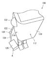
도 1은 실시 형태 1에 관한 로봇 시스템(1)을 도시하는 개략도이다. 로봇 시스템(1)은 로봇(100)과, 로봇의 동작을 제어하는 제어 장치(2)를 갖는다. 로봇(100)은 몸통체(110)와 로봇 아암(120)을 갖는다. 몸통체(110)는 몸통체 전방면(112)과 몸통체 측면(114)을 갖는다. 1 is a schematic view showing a robot system 1 according to a first embodiment. The robot system 1 has a
또한, 실제 로봇(100)의 바디(실제 몸통체)는, 임의의 복수의 곡면으로 구성된 형상으로 형성되어 있지만, 본 실시 형태에서는, 모식적으로, 몸통체(110)를, 실제 몸통체를 내포하는 직육면체 Bd라고 생각한다. 또한, 본 실시 형태에 있어서는, 몸통체(110)를, 로봇 아암(120)과의 간섭 대상으로 되는 장해물로 하고 있다. 따라서, 본 실시 형태에 있어서는, 몸통체(110)는 장해물을 포함하는 장해물 영역(상기 「직육면체 Bd」에 대응)이며, 몸통체 전방면(112) 및 몸통체 측면(114)은 장해물을 포함하는 장해물 영역의 경계면이다. Although the body (actual body) of the
로봇 아암(120)은 몸통체 측면(114)에 접속되어 있다. 또한, 도 1은 로봇(100)의 오른팔에 대응하는 로봇 아암(120)만이 도시되어 있지만, 로봇(100)은 왼팔에 대응하는 로봇 아암(120)을 가져도 된다. 또한, 로봇(100)은 1개 이상(예를 들어 2개)의 다리를 가져도 된다. 이하, 로봇(100)의 오른팔에 대응하는 로봇 아암(120)에 대한 제어 방법(간섭 회피 방법)에 대해서 설명하지만, 이에 한정되지 않는다. 본 실시 형태에 관한 제어 방법은, 로봇(100)의 왼팔에 대응하는 로봇 아암 및 로봇(100)의 다리에 대해서도 적용 가능하다. 즉, 「아암(로봇 아암)」이란, 팔에 상당하는 아암, 다리에 상당하는 아암 및 아암형 로봇의 아암을 포함한다. The
또한, 로봇 아암(120)은 몸통체(110)에 가까운 쪽으로부터 순서대로, 견부(132)와, 상완부(122)(제1 아암)와, 팔꿈치부(134)(관절부)와, 전완부(124)(제2 아암)와, 손목부(136)와, 손끝부(126)로 구성되어 있다. 몸통체(110)[몸통체 측면(114)]에는 견부(132)가 접속되어 있다. 또한, 팔꿈치부(134)를 통하여, 상완부(122)와 전완부(124)가 접속되어 있다. 또한, 손목부(136)를 통하여 전완부(124)와 손끝부(126)가 접속되어 있다. 또한, 상완부(122)의 길이를 L1로 하고, 전완부(124)의 길이를 L2로 한다. 또한, 후술하는 제어 장치(2)에 있어서의 계산에서는, 상완부(122) 및 전완부(124)는, 각각, 길이 L1 및 L2의 선분인 것으로 가정되어 있다. The
또한, 견부(132)는, 서로 직교한 3축의 주위를 각각 회전하는 3개의 관절[제1 관절부(141), 제2 관절부(142), 제3 관절부(143)]를 갖고 있다. 또한, 팔꿈치부(134)는 1축의 주위를 회전하는 1개의 관절[제4 관절부(144)]을 갖고 있다. 또한, 손목부(136)는, 서로 직교한 3축의 주위를 각각 회전하는 3개의 관절[제5 관절부(145), 제6 관절부(146), 제7 관절부(147)]을 갖고 있다. The
또한, 제1 관절부(141)의 관절 각도를 θ1로 하고, 제2 관절부(142)의 관절 각도를 θ2로 하고, 제3 관절부(143)의 관절 각도를 θ3으로 한다. 마찬가지로, 제4 관절부(144)의 관절 각도를 θ4로 하고, 제5 관절부(145)의 관절 각도를 θ5로 하고, 제6 관절부(146)의 관절 각도를 θ6으로 하고, 제7 관절부(147)의 관절 각도를 θ7로 한다. The joint angle of the first joint 141 is θ 1 , the joint angle of the second joint 142 is θ 2 , and the joint angle of the third joint 143 is θ 3 . Similarly, assuming that the joint angle of the fourth
또한, 본 실시 형태에 있어서는, 후술하는 제어 장치(2)에 있어서의 계산에서는, 견부(132)를 1점으로 모의하고 있다. 즉, 제1 관절부(141), 제2 관절부(142), 제3 관절부(143)가, 1개의 점에서 교차하고 있다고 가정하고 있다. 마찬가지로, 후술하는 제어 장치(2)에 있어서의 계산에서는, 손목부(136)를 1점으로 모의하고 있다. 즉, 제5 관절부(145), 제6 관절부(146), 제7 관절부(147)가, 1개의 점으로 교차하고 있다고 가정하고 있다. 이 경우, 견부(132)의 3개의 관절[제1 관절부(141), 제2 관절부(142), 제3 관절부(143)] 및 손목부(136)의 3개의 관절[제5 관절부(145), 제6 관절부(146), 제7 관절부(147)]은, 각각, 가상적인 구면 구조를 구성하고 있다고 간주할 수 있다. 또한, 본 실시 형태에 있어서의 로봇 아암(120)은, 7개의 관절을 갖고 있기 때문에, 7 자유도를 갖는 매니퓰레이터이다. In the present embodiment, calculation of the
여기서, 견부(132)를 원점 O으로 하는 좌표계를 정의한다. 원점 O을 지나고, 전방측[몸통체 전방면(112)측] 방향(도 1의 지면 안쪽으로부터 전방 방향)을 플러스로 하는 좌표축을 x축으로 한다. 또한, 원점 O을 지나고, 몸통체의 우측으로부터 좌측으로 향하는 방향(도 1의 좌측으로부터 우측 방향)을 플러스로 하는 좌표축을 y축으로 한다. 또한, 원점 O을 지나고, 상측을 향하는 방향(도 1의 상측 방향)을 플러스로 하는 좌표축을 z축으로 한다. Here, a coordinate system in which the
제어 장치(2)는, 예를 들어, 컴퓨터로서의 기능을 갖는다. 제어 장치(2)는 로봇(100)의 내부에 탑재되어도 좋고, 로봇(100)과 유선 또는 무선을 통하여 통신 가능하게 접속되어도 된다. 제어 장치(2)는 로봇(100)의 동작, 특히, 로봇 아암(120)의 동작을 제어한다. 즉, 로봇 시스템(1)에 있어서, 제어 장치(2)는 마스터 장치로서의 기능을 갖고, 로봇(100)[로봇 아암(120)]은 슬레이브 장치로서의 기능을 갖는다. 여기서, 제어 장치(2)는 로봇 아암(120)의 몸통체(110) 등의 장해물에 대한 간섭을 회피하도록, 로봇 아암(120)의 각 관절 각도를 결정한다. 상세하게는 후술한다. The
여기서, 본 실시 형태에 있어서 사용되는 「아암 앵글」이라고 하는 지표에 대해서 설명한다. 「아암 앵글」에 대해서는, 문헌 「관절의 가동 범위를 고려한 7 자유도 용장 매니퓰레이터의 해석적 역운동학 해법」(일본 로봇 학회지 Vol. 25 No. 4, pp.606 내지 617, 2007)에 기재되어 있다. 이하, 간단하게 설명한다. Here, an index called " arm angle " used in the present embodiment will be described. For the "arm angle", an analytical inverse kinematics solution of a 7-DOF redundant manipulator considering the range of motion of the joint (Japanese Robotics Journal Vol. 25 No. 4, pp.606 to 617, 2007) . Hereinafter, a brief description will be given.
일반적으로, 공간 내에서의 매니퓰레이터의 손끝 위치 및 자세는, 6개의 파라미터에서 일의적으로 표현될 수 있다. 따라서, 7 자유도 매니퓰레이터에서는, 여분의 자유도가 1개 존재한다. 이 용장 자유도에 의해, 7 자유도 매니퓰레이터에서는, 손끝 위치 및 자세에 영향을 미치지 않는 기구 내부에 있어서의 1 자유도의 셀프 모션이 가능하다. 여기서, 상술한 바와 같이, 본 실시 형태에 관한 로봇 아암(120)은 7 자유도를 갖는다. 따라서, 본 실시 형태에 관한 로봇 아암(120)은, 1개의 용장 자유도를 갖고 있다. 본 실시 형태에서는, 이 용장 자유도를 나타내는 파라미터로서, 「아암 앵글」이라고 하는 지표가 사용된다. Generally, the fingertip position and attitude of a manipulator in a space can be expressed uniquely in six parameters. Thus, in a 7-degree-of-freedom manipulator, there is one extra degree of freedom. By this redundancy degree of freedom, self-motion of one degree of freedom is possible in a mechanism that does not affect the fingertip position and posture in the 7-degree freedom manipulator. Here, as described above, the
도 2는 실시 형태 1에 관한 아암 앵글에 대해서 설명하기 위한 도면이다. 상술한 바와 같이, 견부(132)의 3개의 관절 및 손목부(136)의 3개의 관절은, 각각, 가상적인 구면 구조를 구성하고 있다. 이에 의해, 손끝부(126)의 위치 및 자세를 지정하여, 로봇 아암(120)의 양단부, 즉 견부(132)의 위치(점 O)와 손끝부(126)의 위치(점 P)를 고정해도, 용장 자유도에 의해, 팔꿈치부(134)의 위치(점 e)는 변화할 수 있다. 또한, 이하, 손끝부(126)의 위치는, 가상적으로 점으로 표시된다. 즉, 손목부(136) 및 손끝부(126)의 위치는, 서로 동일하다고 가정한다. Fig. 2 is a view for explaining the arm angle according to the first embodiment. Fig. As described above, the three joints of the
도 2에 도시하는 바와 같이, 손끝부(126)의 위치(점 P)를 지정하면, 견부(132)(점 O)와, 팔꿈치부(134)(점 e)와, 손끝부(126)(점 P)를 정점으로 하고, 상완부(122)와, 전완부(124)와, 선분 OP를 3변으로 하는 삼각형 O-e-P가 정해진다. 이때, 삼각형 O-e-P는, 선분 OP를 중심으로 하여, 화살표 A에 나타내는 바와 같이 회전 가능하다. 이와 같이, 선분 OP를 중심으로 하여 팔꿈치부(134)의 위치(점 e)를 회전시킨 경우의 팔꿈치부(134)의 위치(점 e)의 회전 각도를, 아암 앵글 φ로 한다. 또한, 미리 정해진 참조 평면 상에 팔꿈치부(134)의 위치가 있는 경우에 그 위치를 점 e0으로 하면, 삼각형 O-e0-P에 있어서의 아암 앵글을 φ=0으로 한다. 그리고, 점 P로부터 점 O을 보아 점 e를 시계 방향으로 회전시키는 방향(화살표 A의 방향)을, 아암 앵글의 플러스 방향으로 한다. 바꾸어 말하면, 아암 앵글의 플러스 방향은, 점 P로부터 점 O의 방향으로 엄지 손가락을 세운 오른손의 법칙에 의해 정의된다. 아암 앵글 φ를 플러스 방향으로 회전시키면, 팔꿈치부(134)의 위치 e는, φ=0인 점 e0으로부터, e1, e2, e3으로 이동한다. 2, when the position (point P) of the
또한, 이와 같이, 선분 OP를 중심으로 하여 팔꿈치부(134)의 위치(점 e)를 회전시킨 경우에 상완부(122) 및 전완부(124)가 그리는 궤적이, 각각, 손끝부(126)의 위치(점 P)가 지정된 경우의 상완부(122) 및 전완부(124)의 가동 영역이다. 상완부(122) 및 전완부(124)의 가동 영역은 팔꿈치부(134)를 회전한 궤적에 의해 형성된 원을 저면으로 하고, 상완부(122) 및 전완부(124)가 회전한 궤적에 의해 형성된 회전면을 각각 측면으로 하는 원추로 형성된다. When the position (point e) of the
도 3은 실시 형태 1에 관한 제어 장치(2)의 구성을 도시하는 기능 블록도이다. 제어 장치(2)는 주요한 하드웨어 구성으로 하고, CPU(Central Processing Unit)(4)와, ROM(Read Only Memory)(6)과, RAM(Random Access Memory)(8)을 갖는다. CPU(4)는 제어 처리 및 연산 처리 등을 행하는 연산 장치로서의 기능을 갖는다. ROM(6)은 CPU(4)에 의해 실행되는 제어 프로그램 및 연산 프로그램 등을 기억하기 위한 기능을 갖는다. RAM(8)은 처리 데이터 등을 일시적으로 기억하기 위한 기능을 갖는다. 3 is a functional block diagram showing the configuration of the
또한, 제어 장치(2)는 정보 저장부(12), 손끝 위치 결정부(14), 가동 영역 산출부(16), 교점 산출부(18), 간섭 회피 범위 결정부(20), 관절 각도 산출부(22) 및 로봇 아암 제어부(24)(이하, 「각 구성 요소」라고 칭함)를 갖는다. 정보 저장부(12), 손끝 위치 결정부(14), 가동 영역 산출부(16), 교점 산출부(18), 간섭 회피 범위 결정부(20), 관절 각도 산출부(22) 및 로봇 아암 제어부(24)는, 각각, 정보 저장 수단, 손끝 위치 결정 수단, 가동 영역 산출 수단, 교점 산출 수단, 간섭 회피 범위 결정 수단, 관절 각도 산출 수단 및 로봇 아암 제어 수단으로서의 기능을 갖는다. 각 구성 요소는, 예를 들어, CPU(4)가 ROM(6)에 기억된 프로그램을 실행함으로써 실현 가능하다. 또한, 필요한 프로그램을 임의의 불휘발성 기록 매체(비일시적인 컴퓨터 가독 매체)에 기록해 두고, 필요에 따라서 인스톨하도록 해도 된다. 또한, 각 구성 요소는, 상기와 같이 소프트웨어에 의해 실현되는 것에 한정되지 않고, 어떠한 회로 소자 등의 하드웨어에 의해 실현되어도 된다. 각 구성 요소의 기능에 대해서는, 도 4를 사용해서 설명한다. The
도 4는 실시 형태 1에 관한 제어 장치(2)의 처리를 도시하는 흐름도이다. 우선, 스텝 S102에 있어서, 제어 장치(2)는 로봇 아암(120)의 제어에 필요한 정보를 정보 저장부(12)에 저장시킴으로써, 사전 설정을 행한다. 정보 저장부(12)는 상완부(122)의 길이 L1 및 전완부(124)의 길이 L2를 저장한다. 또한, 정보 저장부(12)는 몸통체(110)(장해물 영역)에 관한 위치 정보를 저장한다. 구체적으로는, 정보 저장부(12)는 견부(132)를 원점 O으로 하는 xyz 좌표계에 있어서의, 몸통체(110)의 위치 정보(좌표 데이터)를 기억하고 있다. 더욱 구체적으로는, 정보 저장부(12)는 몸통체 전방면(112)을 나타내는 위치 정보(좌표 데이터) 및 몸통체 측면(114)을 나타내는 위치 정보(좌표 데이터)를 저장한다. 또한, 정보 저장부(12)는, 도 1에 도시하는 선분 AB를 나타내는 위치 정보(좌표 데이터)를 저장한다. 이 선분 AB는, 후술하는 바와 같이, 간섭의 회피를 판정하기 위한 간섭 판정 선분 Ld(제1 선)로서 사용된다. 4 is a flowchart showing the processing of the
또한, 정보 저장부(12)에 기억되는 몸통체(110)의 좌표 데이터는, 실제의 로봇 아암(120)의 굵기를 고려한, 간섭을 검출하기 위해 사용되는 몸통체(110)에 대응하는 장해물의 3차원 형상을 나타내고 있다. 또한, 몸통체(110)의 좌표 데이터는, 실제의 몸통체(110)를 내포하는 장해물 영역의 경계면의 좌표를 나타내고 있다. 즉, 몸통체(110)에 대응하는 장해물 영역의 좌표 데이터는 로봇 아암(120)의 굵기에 대응하는 마진이 포함되어 있다. The coordinate data of the
다음에, 스텝 S104에 있어서, 제어 장치(2)는 손끝부(126)의 위치(목표 손끝 위치)를 결정한다. 구체적으로는, 제어 장치(2)의 손끝 위치 결정부(14)는 조작자가 키보드, 마우스 또는 햅틱 디바이스 등의 입력 수단을 사용해서 입력한 목표 손끝 위치의 좌표 데이터를 접수한다. 이에 의해, 손끝부(126)의 위치 및 자세가 지정된다. Next, in step S104, the
다음에, 스텝 S106에 있어서, 제어 장치(2)는 손끝부(126)의 간섭 판정을 행한다. 여기서, S106에 있어서의 간섭 판정은 손끝부(126)가 몸통체(110)와 간섭하는지 여부의 판정이다. 구체적으로는, 손끝 위치 결정부(14)는 지정된 목표 손끝 위치로부터, 손끝부(126)가 몸통체(110)와 간섭하는지 여부를 판정한다. 예를 들어, 손끝 위치 결정부(14)는 손끝부(126) 및 몸통체(110)를 폴리곤으로 나타내고, OBB(Oriented Bounding Box:유향 경계 박스)를 사용함으로써, 손끝부(126)가 몸통체(110)와 간섭하는지 여부를 판정해도 된다. Next, in step S106, the
손끝부(126)의 간섭이 발생하는 경우(S106의 "예"), 스텝 S140에 있어서, 제어 장치(2)는 목표 손끝 위치의 수정 처리를 행한다. 구체적으로는, 제어 장치(2)는, S102의 처리에 의해 지정된 목표 손끝 위치를 캔슬한다. 그리고, 제어 장치(2)는, 조작자가 지정한 목표 손끝 위치에서는 간섭이 발생하므로 다시 목표 손끝 위치를 지정하도록, 조작자에 대해 통지한다. If interference of the
한편, 손끝부(126)의 간섭이 발생하지 않는 경우(S106의 "아니오"), 스텝 S108에 있어서, 제어 장치(2)는 로봇 아암(120)의 가동 영역을 산출한다. 구체적으로는, 제어 장치(2)의 가동 영역 산출부(16)는, 상술한 아암 앵글 φ를 사용해서, 상완부(122) 및 전완부(124)의 가동 영역을 산출한다. 또한, 이때에 산출되는 「가동 영역」은 로봇 아암(120)의 주위의 장해물과의 간섭에 대해서는 고려되어 있지 않다. 이하, 가동 영역 산출부(16)에 있어서의 계산 방법을 설명한다. On the other hand, when interference of the
도 5는 실시 형태 1에 관한 가동 영역의 산출 방법을 설명하기 위한 도면이다. S104에 있어서, 손끝부(126)의 위치 P가 P0 [X, Y, Z]T로 지정되었다고 한다. 가동 영역 산출부(16)는, 도 5의 (A)에 도시하는 바와 같이, 견부(132)의 위치(원점 O)와 손끝부(126)의 위치 P 사이의 거리(√(X2+Y2+Z2))를 유지한 채로, 손끝부(126)의 위치 P를 z축의 연직 하측 방향의 위치(점 P')에 둔다. 이때, 점 P'의 좌표는 [0, 0, -√(X2+Y2+Z2)]이다. 또한, 가동 영역 산출부(16)는 팔꿈치부(134)의 위치 e를 xz 평면 상의 x<0의 영역 위치(e')에 둔다. 이에 의해, 견부(132)(점 O)와, 팔꿈치부(134)(점 e)와, 손끝부(126)(점 P)를 정점으로 하는 삼각형 O-e-P(O-e'-p')는 xz 평면 상에 존재하게 된다. 5 is a diagram for explaining a calculation method of the movable area according to the first embodiment. In the S104, and that the position P of the
그리고, 가동 영역 산출부(16)는, 도 5의 (B)에 도시하는 바와 같이, 손끝부(126)의 위치 P가 S104의 처리에 의해 지정된 손끝 위치 P0에 일치하도록, 삼각형 O-e-P를, x축 주위로 회전각 α로 회전하고, y축 주위로 회전각 β로 회전한다. 구체적으로는, 가동 영역 산출부(16)는, 이하의 수학식 1 및 수학식 2를 사용해서, 점 P' 및 점 e'를, 각각 점 P0 및 점 e0으로 변환한다. A and the movable
![]()
![]()
![]()
![]()
여기서, 수학식 1 및 수학식 2에 있어서, P', e', P0 및 e0은, 각각 점 P', 점 e', 점 P0 및 점 e0에 관한 위치 벡터이다. 또한, Rα는, 회전각 α를 나타내는 회전 행렬을 나타낸다. 또한, Rβ는, 회전각 β를 나타내는 회전 행렬을 나타낸다. 또한, 로봇 아암(120)의 링크 길이(L1 및 L2)는 미리 정해져 있으므로, e0 및 e'를 산출할 수 있고, 상기 수학식 1 및 수학식 2로부터, α 및 β는 일의적으로 산출 가능하다. In the equations (1) and (2), P ', e', P 0 and e 0 are position vectors related to the point P ', the point e', the point P 0 and the point e 0 , respectively. R ? Represents a rotation matrix representing the rotation angle?. R ? Represents a rotation matrix representing the rotation angle?. In addition, since the link lengths (L 1 and L 2 ) of the
가동 영역 산출부(16)는, 도 5의 (B)에 나타낸 회전 후의 삼각형 O-e0-P0(사선으로 나타냄)을 포함하는 평면을, 아암 앵글의 기준이 되는 참조 평면으로 한다. 즉, 가동 영역 산출부(16)는 팔꿈치부(134)의 위치 e가 점 e0에 있는 경우에, 아암 앵글을 φ=0으로 한다. A plane including the movable
그리고, 도 5의 (C)에 도시하는 바와 같이, 가동 영역 산출부(16)는 견부(132)를 원점 O으로 고정하고, 손끝부(126)를 점 P0으로 고정한 상태에서, OP 주위로 상완부(122) 및 전완부(124)를 화살표 A의 방향으로 회전시킨 궤적을 산출한다. 이 궤적은 손끝부(126)의 위치(점 P)가 점 P0으로 지정된 경우의 상완부(122) 및 전완부(124)의 가동 영역이다. 그리고, 가동 영역은 팔꿈치부(134)를 회전한 궤적에 의해 형성된 원을 저면으로 하고, 상완부(122) 및 전완부(124)가 회전한 궤적에 의해 형성된 회전면을 각각 측면으로 하는 원추로 형성된다. 바꾸어 말하면, 로봇 아암(120)의 가동 영역은 저면이 서로 합쳐진 2개의 원추로 형성된다. Then, the calculated moving
도 6은 실시 형태 1에 관한 가동 영역 산출부(16)에 의해 산출된 원추의 각 치수를 정의하기 위한 도면이다. 가동 영역 산출부(16)는 전완부(124)의 궤적에 의해 형성된 원추 CL(제1 원추) 및 상완부(122)의 궤적에 의해 형성된 원추 CU(제2 원추) 각각에 대한 치수를 산출한다. 여기서, 선분 OP의 길이를 L0으로 한다. 또한, 원추 CU의 저면은 원추 CL의 저면과 공통되어 있으므로, 각각의 저면인 원의 반경 r은 동일하다. 여기서, 원추 CU의 높이를 k1로 하고, 원추 CL의 높이를 k2로 한다. 이때, k1+k2=L0이다. 또한, 이때, 팔꿈치부(134)의 위치 e로부터 선분 OP에 내린 수선의 발을 H로 하면, k1=OH이며, k2=PH이다. 또한, 원추 CU는 삼각형 O-e-H를 선분 OH의 주위로 회전시킨 궤적이다. 마찬가지로, 원추 CL은 삼각형 P-e-H를 선분 PH의 주위로 회전시킨 궤적이다. 6 is a diagram for defining respective dimensions of a cone calculated by the movable
여기서, 상술한 바와 같이, 상완부(122)의 길이 L1 및 전완부(124)의 길이 L2는, 미리 정해져 있다. 또한, 손끝부(126)의 위치가 점 P0으로 지정됨으로써, 선분 OP의 길이도 정해져 있다. 따라서, 삼각형 O-e-P는, 아암 앵글에 치우치지 않고 일의적으로 정해진다. 따라서, 가동 영역 산출부(16)는 코사인 정리를 사용해서, r, k1, k2를 산출할 수 있다. Here, as described above, the length L 1 of the
또한, 가동 영역 산출부(16)는 전완부(124)의 궤적인 원추 CL에 대해서, 정점(점 P)이 z'축 상에 놓이고, 저면이 x' y' 평면 상에 놓이도록, 좌표계(x, y, z)로부터 좌표계(x', y', z')로의 좌표 변환을 행한다. 구체적으로는, 가동 영역 산출부(16)는, 이하의 수학식 3을 사용해서, 원추 CL에 대한 좌표 변환을 행한다. The movable

수학식 3에 있어서, 상기 수학식 1 및 수학식 2에서 사용된 회전 행렬 Rα 및 회전 행렬 Rβ를 사용함으로써, 선분 PH가 z'축 상이 되도록, 좌표계가 변환된다. 이것은, 도 5의 (A)에 나타낸 좌표계를 (x, y, z)로부터 (x', y', z')로 치환하고, 전완부(124)를 OP 주위로 회전시킨 궤적에 상당한다. 또한, 정점(점 P)을 z'축의 플러스의 측에 두기 위해, 좌표계는, z축(z'축)의 부호가 플러스로부터 마이너스로 변환된다. 또한, 저면을 x' y' 평면(즉 z'=0의 평면) 상으로 이동시키기 위해, 좌표계는 z'축 방향으로 -k1 오프셋되어 있다. 이에 의해, 도 6에 도시한 점 H가, 좌표계(x', y', z')의 원점 O'에 일치한다. In Equation (3), by using the rotation matrix R alpha and the rotation matrix R beta used in Equations (1) and (2), the coordinate system is transformed such that the line segment PH is on the z 'axis. This corresponds to a locus obtained by replacing the coordinate system shown in FIG. 5A with (x ', y', z ') from (x, y, z) and rotating the
또한, 가동 영역 산출부(16)는 변환 후의 원추 저면의 식을 이하의 수학식 4로 산출하고, 변환 후의 원추면(측면)의 식을 이하의 수학식 5로 산출한다. Further, the movable
![]()
![]()

마찬가지로, 가동 영역 산출부(16)는 산출된 원추 CU에 대해서, 정점(점 O)이 z'축 상에 놓이고, 저면이 x' y' 평면 상에 놓이도록, 좌표계(x, y, z)로부터 좌표계(x', y', z')로의 좌표 변환을 행한다. 구체적으로는, 가동 영역 산출부(16)는, 이하의 수학식 6을 사용해서, 원추 CU에 대한 좌표 변환을 행한다. Likewise, for the calculated cone CU, the movable

수학식 6에 있어서, 수학식 3과 마찬가지로, 상기 수학식 1 및 수학식 2에서 사용된 회전 행렬 Rα 및 회전 행렬 Rβ를 사용함으로써, 선분 OP가 z'축 상이 되도록, 좌표계가 변환된다. 또한, 저면을 x' y' 평면(즉 z'=0의 평면) 상으로 이동시키기 위해, 좌표계는 z'축 방향으로 k1 오프셋되어 있다. 이에 의해, 도 6에 도시한 점 H가, 좌표계(x', y', z')의 원점 O'에 일치한다. In Equation (6), the coordinate system is transformed so that the line segment OP is on the z 'axis by using the rotation matrix R alpha and the rotation matrix R beta used in Equations (1) and (2), as in Equation (3). Also, to move the bottom surface onto the x 'y' plane (ie the plane with z '= 0), the coordinate system is offset k 1 in the z' axis direction. Thus, the point H shown in Fig. 6 coincides with the origin O 'of the coordinate system (x', y ', z').
또한, 가동 영역 산출부(16)는 변환 후의 원추 저면의 식을 상기 수학식 4로 산출하고, 변환 후의 원추면(측면)의 식을 이하의 수학식 7로 산출한다. Further, the movable

도 7a 및 도 7b는 실시 형태 1에 관한 가동 영역 산출부(16)에 의해 산출된 원추를 도시하는 도면이다. 이상과 같이 하여, 가동 영역 산출부(16)는, 도 7a에 도시하는 바와 같은 원추 CL을 산출하고, 도 7b에 도시하는 바와 같은 원추 CU를 산출한다. 여기서, 팔꿈치부(134)의 위치 e가 참조 평면에 있는 경우[도 5의 (B)]의 위치 e0을 좌표 변환하면, 변환 후의 위치 e0'의 좌표는 [-r, 0, 0]이 된다. 이 위치에 있어서, 아암 앵글이 φ=0이 된다. 또한, 아암 앵글의 플러스 방향은, 도 7b에 도시하는 바와 같이, 원추 CU에 대해서는, 도 2의 화살표 A로부터, z'축의 플러스 방향에서 보아 반시계 방향으로 된다. 한편, 원추 CL에 대해서는, 좌표 변환 시에 z축(z'축)의 부호가 플러스로부터 마이너스로 변환된 것에 수반하여, 아암 앵글의 플러스 방향은, 도 7a에 도시하는 바와 같이, 원추 CU와는 반대의, z'축의 플러스 방향에서 보아 시계 방향이 된다. 7A and 7B are diagrams showing cones calculated by the movable
다음에, 스텝 S110에 있어서, 제어 장치(2)는 가동 영역과, 간섭 판정 선분 Ld와의 교점을 산출한다. 또한, 스텝 S112 내지 S120에 있어서, 제어 장치(2)는 산출된 교점을 사용해서, 로봇 아암(120)이 가동 영역에서 몸통체(110)에 간섭하지 않는 범위(간섭 회피 범위)를 결정한다. 이하, 본 실시 형태에 있어서의, 아암 앵글을 사용한 간섭 회피 범위를 결정하는 메커니즘을 설명한다. Next, in step S110, the
상술한 바와 같이, 손끝부(126)의 위치를 지정한 경우에, 로봇 아암(120)의 가동 영역은 아암 앵글 φ를 회전시킨 궤적인 2개의 원추 CU 및 CL로 표시된다. 여기서, 몸통체(110)와 로봇 아암(120)과의 간섭을 회피하기 위해서는, 몸통체(110)의 외부에 로봇 아암(120)이 존재하도록 하면 된다. 바꾸어 말하면, 원추 CU의 측면 상의, 견부(132)와 팔꿈치부(134)를 연결하는 선분(원추 CU의 모선) 및 원추 CL의 측면 상의, 팔꿈치부(134)와 손끝부(126)를 연결하는 선분(원추 CL의 모선)이, 몸통체(110)를 모의한 직육면체 Bd의 내부에 침입하지 않도록 하면 된다. 즉, 원추 CU의 모선 및 원추 CL의 모선이 직육면체 Bd의 내부에 침입하지 않는 아암 앵글의 범위를 결정하면 된다. As described above, in the case where the position of the
도 8a, 도 8b 및 도 8c는 실시 형태 1에 관한 로봇(100)의 몸통체(110)와 로봇 아암(120)과의 관계에 대해서 도시하는 도면이다. 도 8a, 도 8b 및 도 8c에 있어서는, 손끝부(126)의 위치에 따른, 가동 영역(원추 CU 및 CL)과, 몸통체(110)(직육면체 Bd)와의 위치 관계에 대해서 도시되어 있다. 손끝부(126)의 위치가 도 8a에 도시하는 위치에 지정된 경우, 가동 영역(원추 CU 및 CL)의 일부가, 직육면체 Bd의 내부에 침입하고 있다. 따라서, 이 경우에는 가동 영역(원추 CU 및 CL) 중 직육면체 Bd의 내부에 침입하지 않는 아암 앵글의 범위(간섭 회피 범위)를 결정하면 된다. 8A, 8B and 8C are diagrams showing the relationship between the
여기서, 도 8a에 도시하는 바와 같은 케이스에서는, 가동 영역(원추 CU 및 CL)은, 몸통체 측면(114) 및 몸통체 전방면(112)의 양쪽과 교차하고 있다. 이에 의해, 가동 영역(원추 CU 및 CL)은 선분 AB(간섭 판정 선분 Ld)와 교차하고 있다. 따라서, 본 실시 형태에 있어서는, 이 가동 영역(원추 CU 및 CL)과 선분 AB(간섭 판정 선분 Ld)와의 교점을 사용해서, 간섭 회피 범위가 결정된다. Here, in the case shown in Fig. 8A, the movable region (cones CU and CL) intersects both the
또한, 손끝부(126)의 위치가 도 8b에 도시하는 위치에 지정된 경우, 견부(132) 근방 및 손끝부(126)의 근방을 제외하고, 가동 영역(원추 CU 및 CL)의 모두가, 직육면체 Bd의 내부에 침입하고 있다. 이 경우는 몸통체(110)와 로봇 아암(120)과의 간섭을 회피할 수 없다. 따라서, 간섭 회피 범위는 존재하지 않는다고 결정된다. 또한, 도 8b에 도시하는 바와 같은 케이스에서는, 가동 영역(원추 CU 및 CL)은, 선분 AB(간섭 판정 선분 Ld)와 교차하지 않는다. 8B, all of the movable regions (cones CU and CL) except for the vicinity of the
또한, 손끝부(126)의 위치가 도 8c에 도시하는 위치에 지정된 경우에 있어서도, 가동 영역(원추 CU 및 CL)은 선분 AB(간섭 판정 선분 Ld)와 교차하지 않는다. 한편, 도 8c의 케이스에서는, 가동 영역(원추 CU 및 CL)의 모두가 직육면체 Bd의 외측에 존재하고 있거나, 또는, 가동 영역(원추 CU 및 CL)이 몸통체 측면(114)으로만 교차하고 있다. 따라서, 이 경우에서는 가동 영역(원추 CU 및 CL)과 몸통체 측면(114)과의 관계로부터 간섭 회피 범위가 결정된다. Further, even when the position of the
스텝 S110에 대해서 설명한다. 제어 장치(2)의 교점 산출부(18)는, 도 7a 및 도 7b에 도시한 원추와, 간섭 판정 선분 Ld(도 1의 선분 AB)와의 교점을 산출한다. 교점 산출부(18)는 원추 CL과 간섭 판정 선분 Ld와의 교점을 산출하고, 원추 CU와 간섭 판정 선분 Ld와의 교점을 산출한다. 바꾸어 말하면, 교점 산출부(18)는 원추 CL과 원추 CU로 별개로 교점을 산출한다. 이하, 원추 CL과 원추 CU로, 나누어서 설명한다. Step S110 will be described. The
구체적으로는, 교점 산출부(18)는 원추 CL과 간섭 판정 선분 Ld와의 교점을 산출할 때에, 상기 수학식 3을 사용해서, 점 A의 좌표 및 점 B의 좌표를 좌표계(x, y, z)로부터 좌표계(x', y', z')로 변환한다. 이에 의해, 교점 산출부(18)는 점 A를 변환한 점 A'의 좌표 및 점 B를 변환한 점 B'의 좌표를 얻는다. 또한, 교점 산출부(18)는, 이하의 수학식 8과 같이, 간섭 판정 선분 Ld(선분 A' B') 상의 점 PLd를 나타내는 식을 산출한다. Specifically, when calculating the intersection point between the cone CL and the interference determination line segment Ld, the

여기서, 수학식 8에 있어서, t는 매개 변수이다. 또한, 수학식 8에 있어서, PLd는 점 PLd의 위치 벡터[x', y', z']T이다. 마찬가지로, 수학식 8에 있어서, A' 및 B'는, 각각, 점 A' 및 점 B'의 위치 벡터이다. 교점 산출부(18)는 수학식 8을 수학식 4 및 수학식 5에 대입하여, 얻어진 2차 방정식에 있어서의 t의 해를 산출한다. 수학식 4를 만족하는 t의 실수가 존재하는 경우, 교점 산출부(18)는 원추 CL의 저면과 간섭 판정 선분 Ld와의 교점이 존재한다고 판정한다. 또한, 수학식 5를 만족하는 t의 실수가 존재하는 경우, 교점 산출부(18)는 원추 CL의 측면(원추면)과 간섭 판정 선분 Ld와의 교점이 존재한다고 판정한다. 그리고, 교점 산출부(18)는 얻어진 t의 값으로부터, 교점을 산출한다. Here, in Equation (8), t is a parameter. In Equation (8), P Ld is the position vector [x ', y', z '] T of the point P Ld . Similarly, in the equation (8), A 'and B' are position vectors of the points A 'and B', respectively. The
마찬가지로, 교점 산출부(18)는 원추 CU와 간섭 판정 선분 Ld와의 교점을 산출할 때에, 상기 수학식 6을 사용해서, 점 A의 좌표 및 점 B의 좌표를 좌표계(x, y, z)로부터 좌표계(x', y', z')로 변환한다. 이에 의해, 교점 산출부(18)는 점 A를 변환한 점 A'의 좌표 및 점 B를 변환한 점 B'의 좌표를 얻는다. 또한, 교점 산출부(18)는 원추 CL의 경우와 마찬가지로 하여, 상기 수학식 8과 같이, 간섭 판정 선분 Ld(선분 A' B') 상의 점 PLd를 나타내는 식을 산출한다. 그리고, 교점 산출부(18)는 원추 CL의 경우와 마찬가지로, 수학식 8을 수학식 4 및 수학식 7에 대입하여, t의 해를 산출한다. 수학식 4를 만족하는 t의 실수가 존재하는 경우, 교점 산출부(18)는 원추 CU의 저면과 간섭 판정 선분 Ld와의 교점이 존재한다고 판정한다. 또한, 수학식 7을 만족하는 t의 실수가 존재하는 경우, 교점 산출부(18)는 원추 CU의 측면(원추면)과 간섭 판정 선분 Ld와의 교점이 존재한다고 판정한다. 그리고, 교점 산출부(18)는 얻어진 t의 값으로부터, 교점을 산출한다. Similarly, when calculating the intersection point between the cone CU and the interference determination line segment Ld, the
스텝 S112에 있어서, 제어 장치(2)의 교점 산출부(18)는 가동 영역(원추 CU 및 CL)과 선분 A' B'(간섭 판정 선분 Ld)와의 교점이 존재하는지 여부를 판정한다. 교점이 존재하지 않는다고 판정된 경우(S112의 "아니오"), 처리는 스텝 S142로 진행한다. 한편, 교점이 존재한다고 판정된 경우(S112의 "예"), 처리는 스텝 S114로 진행한다. In step S112, the
스텝 S142에 있어서, 제어 장치(2)는 간섭 회피 범위가 있는지 여부를 판정한다. 구체적으로는, 제어 장치(2)의 간섭 회피 범위 결정부(20)는 가동 영역(원추 CU 및 CL)과 몸통체(110)와의 위치 관계가 도 8c에 도시하는 관계에 있거나, 또는 도 8b에 도시하는 관계에 있는지를 판정한다. 예를 들어, 간섭 회피 범위 결정부(20)는 견부(132)와 손끝부(126)를 연결하는 선분(OP)이 몸통체 전방면(112)과 교차하는 경우에, 도 8b에 도시하는 위치 관계인 것으로 판정해도 된다. 한편, 간섭 회피 범위 결정부(20)는 선분 OP가 몸통체 전방면(112)과 교차하지 않는 경우에, 도 8c에 도시하는 위치 관계인 것으로 판정해도 된다. In step S142, the
간섭 회피 범위가 없다고 판정된 경우(S142의 "아니오"), 즉 도 8b의 상태인 것으로 판정된 경우, 처리는 S140으로 진행한다. 한편, 간섭 회피 범위가 있다고 판정된 경우(S142의 "예"), 즉 도 8c의 상태인 것으로 판정된 경우, 스텝 S144에 있어서, 간섭 회피 범위 결정부(20)는 가동 영역(원추 CU 및 CL)과 몸통체 측면(114)과의 관계로부터, 간섭을 회피 가능한 아암 앵글의 범위(간섭 회피 범위 φs)를 결정한다. 이 경우, 간섭 회피 범위 결정부(20)는 가동 영역(원추 CU 및 CL)과 몸통체 측면(114)과의 교점으로부터, 몸통체 측면(114)의 외측 영역이 되는 아암 앵글의 범위를, 간섭 회피 범위로서 결정한다. 또한, 가동 영역(원추 CU 및 CL)과 몸통체 측면(114)과의 교점이 없는 경우는, 간섭 회피 범위 결정부(20)는 아암 앵글의 전체 주위를, 간섭 회피 범위 φs로서 결정한다. If it is determined that there is no interference avoiding range ("NO" in S142), that is, if it is determined to be in the state of Fig. 8B, the process proceeds to S140. On the other hand, if it is determined that there is an interference avoiding range (YES in S142), that is, if it is determined that the state is the state shown in Fig. 8C, the interference avoiding
스텝 S114에 있어서, 간섭 회피 범위 결정부(20)는 전완부(124)에 있어서의 아암 앵글의 존재 범위[로봇 아암(120)이 몸통체(110)와 간섭하지 않는 아암 앵글 φ의 범위]를 판정한다. 구체적으로는, 간섭 회피 범위 결정부(20)는 원추 CL의 저면과 간섭 판정 선분 Ld(선분 A' B')와의 교점이 존재하는지 여부를 판정한다. 또한, 간섭 회피 범위 결정부(20)는 원추 CL의 측면(원추면)과 간섭 판정 선분 Ld와의 교점이 몇개인지를 판정한다.In step S114, the interference avoiding
도 9는, 도 7a에 도시한 원추 CL의 측면과 간섭 판정 선분 Ld와의 교점이 2개 존재하는 경우를 예시하는 도면이다. 수학식 8을 수학식 5에 대입하여 얻어진 t의 2차 방정식이 2개의 실수해를 갖는 경우에, 도 9에 도시하는 바와 같이, 원추 CL의 측면과 간섭 판정 선분 Ld(선분 A' B')와의 교점이 2개 존재한다. 또한, 이 경우, 저면과 간섭 판정 선분 Ld와의 교점은 존재하지 않는다. Fig. 9 is a diagram illustrating a case where there are two intersection points between the side of the cone CL and the interference determination line segment Ld shown in Fig. 7A. When the quadratic equation of t obtained by substituting the equation (8) into the equation (5) has two real solutions, the side of the cone CL and the interference determination line segment Ld (segment A 'B' There are two intersection points. In this case, there is no intersection between the bottom surface and the interference determination line segment Ld.
간섭 회피 범위 결정부(20)는 교점 산출부(18)에 의해 산출된 교점 a' 및 b'의 좌표를 취득한다. 그리고, 간섭 회피 범위 결정부(20)는 교점 a'의 좌표를 사용해서, 교점 a'를 원추 CL의 저면에 투영(정사영)한 사상인 점 a"를 산출한다. 또한, 원추 CL은 직원추이며, 저면은 x' y' 평면 상에 있으므로, 교점 a'의 좌표가 [xa', ya', za']인 경우, 점 a"의 좌표는 [xa', ya', 0]이 된다. 마찬가지로, 간섭 회피 범위 결정부(20)는 교점 b'의 좌표를 사용해서, 교점 b'를 원추 CL의 저면에 투영(정사영)한 사상인 점 b"를 산출한다. The interference avoiding
또한, 간섭 회피 범위 결정부(20)는 원추 CL의 저면에 있어서, x'축의 마이너스 방향(점 e0' [-r, 0, 0]을 지나는 반경)을 기준으로 한, 점 a"를 지나는 반경 Ra의 각도 φ1L을 산출한다. 또한, 마찬가지로, 간섭 회피 범위 결정부(20)는 원추 CL의 저면에 있어서, x'축의 마이너스 방향을 기준으로 한, 점 b"를 지나는 반경 Rb의 각도 φ2L을 산출한다. 여기서, 도 7a를 사용해서 상술한 바와 같이, 아암 앵글 φ의 기준점 즉 φ=0의 점은, 점 e0'이다. 따라서, 산출된 각도 φ1L 및 φ2L이, 아암 앵글 φ의 한계 각도(경계 각도)가 된다. 또한, 상술한 바와 같이, 원추 CL에 있어서는, 아암 앵글의 플러스 방향은 z'축 플러스 방향에서 보아 시계 방향이다. 따라서, 도 9와 같이 점 a' 및 점 b'가 위치하고 있는 경우, -π≤φ≤π로 하면, φ1L>0이고, φ2L<0이다. Further, in the bottom face of the determining range
다음에, 간섭 회피 범위 결정부(20)는 산출된 각도 φ1L 및 φ2L을 사용해서, 전완부(124)에 있어서의 아암 앵글의 존재 범위 φL(제1 범위)을 판정한다. 바꾸어 말하면, 간섭 회피 범위 결정부(20)는 로봇 아암(120)의 전완부(124)가 몸통체(110)와 간섭하지 않는 아암 앵글 φ의 존재 범위를 결정한다. 여기서, 각도 φ1L 및 φ2L은 아암 앵글의 존재 범위 φL의 경계 각도이다. 따라서, 원추 CL에 있어서의 아암 앵글의 존재 범위 φL은, φ2L로부터 시계 방향으로 φ1L에 이르는 범위(점 e0'를 포함하는 측)이거나, 또는, φ1L로부터 시계 방향으로 φ2L에 이르는 범위(점 e0'를 포함하지 않는 측) 중 하나이다. 이하, 그 판정 방법에 대해서 설명한다. Next, the interference avoidance
도 10은, 도 9의 예에 있어서의 아암 앵글의 존재 범위 φL의 판정 방법에 대해서 설명하기 위한 도면이다. 도 10에 있어서는, 몸통체 전방면(112) 및 몸통체 측면(114)이 수학식 3을 사용해서 각각 좌표 변환된 평면 F' 및 평면 S'가, 원추 CL에 겹쳐져 있다. 여기서, 아암 앵글의 존재 범위 φL이란, 몸통체(110)와 간섭하지 않는 범위이기 때문에, 원추 CL이 몸통체에 깊이 박히지 않는 측을, 아암 앵글의 존재 범위 φL로 하면 된다. Fig. 10 is a diagram for explaining a method of determining the arm angle existence range? L in the example of Fig. In Fig. 10, the plane F 'and the plane S', which are respectively coordinate-transformed by using the formula (3), are superimposed on the cone CL as the body
예를 들어, 간섭 회피 범위 결정부(20)는 선분 a' b' 상의 임의의 점(예를 들어 중점 g')을 시점으로 하는, 몸통체 전방면(112) 상의 임의의 길이의 벡터 Vf를 산출한다. 그리고, 간섭 회피 범위 결정부(20)는 벡터 Vf를 원추 CL의 저면(즉 x' y' 평면)에 투영(정사영)한다. 그리고, 간섭 회피 범위 결정부(20)는 벡터 Vf의 사상과 교차하지 않는 측의 범위를, 아암 앵글의 존재 범위 φL로서 결정한다. 도 9 및 도 10의 예에서는, 아암 앵글의 존재 범위 φL은 φ2L로부터 시계 방향으로 φ1L에 이르는 범위(φ2L≤φ≤φ1L)가 된다. 또한, 예를 들어, 간섭 회피 범위 결정부(20)는 φ=0을 포함하는 측(점 e0'를 포함하는 측)을, 아암 앵글의 존재 범위 φL로 해도 된다. For example, the interference avoiding
도 11은, 도 7a에 도시한 원추 CL의 저면과 간섭 판정 선분 Ld와의 교점이 1개 존재하는 경우를 예시하는 도면이다. 수학식 4를 만족하는 수학식 8의 t가 1개 존재하는 경우에, 도 11에 도시하는 바와 같이, 원추 CL의 저면과 간섭 판정 선분 Ld(선분 A' B')와의 교점(a')이 1개 존재한다. 또한, 이 경우, 원추 CL의 측면과 간섭 판정 선분 Ld와의 교점(b')은 1개 존재한다. 즉, 수학식 8을 수학식 5에 대입하여 얻어진 t의 2차 방정식이 1개의 실수해를 갖는다. 11 is a diagram exemplifying a case where there is one intersection point between the bottom surface of the cone CL and the interference determination line segment Ld shown in Fig. 7A. (A ') between the bottom surface of the cone CL and the interference determination line segment Ld (segment A' B ') as shown in Fig. 11 exists in the case of one t in Equation There is one. In this case, there is one intersection b 'between the side of the cone CL and the interference determination line segment Ld. That is, the quadratic equation of t obtained by substituting the equation (8) into the equation (5) has one real solution.
도 9의 경우와 마찬가지로, 간섭 회피 범위 결정부(20)는 교점 산출부(18)에 의해 산출된 교점 a' 및 b'의 좌표를 취득한다. 도 11에서는, 점 a'가 저면 상에 있고, 점 b'가 측면 상에 있다. 이 경우, 간섭 회피 범위 결정부(20)는 교점 b'의 좌표를 사용해서, 교점 b'를 원추 CL의 저면에 투영(정사영)한 사상인 점 b"를 산출한다. 또한, 간섭 회피 범위 결정부(20)는 원추 CL의 저면에 있어서, x'축의 마이너스 방향을 기준으로 한, 점 b"를 지나는 반경 Rb의 각도 φ2L을 산출한다. 이 각도 φ2L이, 아암 앵글 φ의 경계 각도의 1개가 된다. 이하, 또 하나의 경계 각도 φ1L의 산출 방법에 대해서 설명한다.9, the interference avoiding
도 12는, 도 11의 예에 있어서의 아암 앵글의 존재 범위 φL의 판정 방법에 대해서 설명하기 위한 도면이다. 상술한 바와 같이, 아암 앵글 φ의 경계 각도의 1개는, φ2L이다. 여기서, 몸통체 전방면(112)의 x' y' z' 좌표계에의 좌표 변환 후의 평면 F'는, 점 a'를 지난다. 이때, 간섭 회피 범위 결정부(20)는 평면 F'와 원추 CL의 저면을 형성하는 원주와의 교점 D'를 산출한다. 또한, 간섭 회피 범위 결정부(20)는 원추 CL의 저면에 있어서, x'축의 마이너스 방향을 기준으로 한, 교점 D'를 지나는 반경 Rd의 각도를 산출한다. 간섭 회피 범위 결정부(20)는 이 각도를, 경계 각도 φ1L로 결정한다. 또한, 간섭 회피 범위 결정부(20)는 x'축의 마이너스 방향을 기준으로 한, 교점 a'를 지나는 반경 Ra의 각도 φa를 포함하는 측의 범위, 즉, φ2L로부터 시계 방향으로 φ1L에 이르는 범위(φ2L≤φ≤φ1L)를, 아암 앵글의 존재 범위 φL로 결정한다. Fig. 12 is a diagram for explaining a method of determining the arm angle existing range? L in the example of Fig. As described above, one of the boundary angles of the arm angle? Is? 2L. Here, the plane F 'after the coordinate transformation to the x' y 'z' coordinate system of the body front face 112 passes the point a '. At this time, the interference avoiding
도 13은, 도 7a에 도시한 원추 CL의 측면과 간섭 판정 선분 Ld와의 교점이 1개 존재하는 경우를 예시하는 도면이다. 수학식 8을 수학식 5에 대입하여 얻어진 t의 2차 방정식이 1개의 중해(重解)를 갖는 경우에, 도 13에 도시하는 바와 같이, 원추 CL의 측면과 간섭 판정 선분 Ld(선분 A' B')와의 교점이 1개 존재한다. 바꾸어 말하면, 간섭 판정 선분 Ld는 원추 CL의 측면과 접한다. 이 간섭 판정 선분 Ld와 원추 CL 측면과의 접점이, 교점이 된다. 또한, 이 경우, 저면과 간섭 판정 선분 Ld와의 교점은 존재하지 않는다. 13 is a diagram illustrating a case where there is one intersection point between the side of the cone CL and the interference determination line segment Ld shown in FIG. 7A. When the quadratic equation of t obtained by substituting the equation (8) into the equation (5) has one middle solution, as shown in Fig. 13, the side of the cone CL and the interference determination line segment Ld &Quot; B "). In other words, the interference determination line segment Ld is in contact with the side surface of the cone CL. The point of contact between the interference determination line segment Ld and the side of the cone CL becomes an intersection point. In this case, there is no intersection between the bottom surface and the interference determination line segment Ld.
이 경우, 간섭 회피 범위 결정부(20)는 견부(132)와 손끝부(126)를 연결하는 선분(OP)이 간섭 판정 선분 Ld보다도 몸통체(110)의 내측을 지나고 있는지 여부를 판정한다. 이 판정은 좌표 변환 후의 좌표계 x' y' z'로 행해져도, 좌표 변환 전의 좌표계 xyz로 행해져도 된다. 선분(OP)이 간섭 판정 선분 Ld보다도 몸통체(110)의 내측을 지나고 있는 경우, 모든 아암 앵글 φ의 범위에서 몸통체(110)와의 간섭을 회피할 수는 없다. 따라서, 간섭 회피 범위 결정부(20)는 아암 앵글의 존재 범위 φL은 존재하지 않는다고 결정한다. 또한, 이 경우, 로봇 아암(120)이 몸통체(110)에 접하는 것이 허용되는 조건이면, 간섭 회피 범위 결정부(20)는, 도 9의 예와 마찬가지로 하여 교점(접점)으로부터 아암 앵글 φ를 산출하고, 그 아암 앵글 φ만을 아암 앵글의 존재 범위 φL로 결정해도 된다. In this case, the interference avoiding
한편, 선분(OP)이 간섭 판정 선분 Ld보다도 몸통체(110)의 외측을 지나고 있는 경우, 모든 아암 앵글 φ의 범위에서 몸통체(110)와 간섭하지 않는다. 따라서, 간섭 회피 범위 결정부(20)는 아암 앵글의 전체 주위를, 아암 앵글의 존재 범위 φL로 결정한다. 또한, 이 경우, 로봇 아암(120)이 몸통체(110)에 접하는 것이 허용되지 않는 조건이면, 간섭 회피 범위 결정부(20)는, 도 9의 예와 마찬가지로 하여 교점(접점)으로부터 아암 앵글 φ를 산출하고, 그 아암 앵글 φ만을 제외한 범위를, 아암 앵글의 존재 범위 φL로 결정해도 된다. On the other hand, when the line segment OP passes through the outer side of the
다음에, 스텝 S116에 있어서, 간섭 회피 범위 결정부(20)는 상완부(122)에 있어서의 아암 앵글의 존재 범위 φU(제2 범위)를 판정한다. 구체적으로는, S114의 처리와 마찬가지로, 간섭 회피 범위 결정부(20)는 원추 CU의 저면과 간섭 판정 선분 Ld(선분 A' B')와의 교점이 존재하는지 여부를 판정한다. 또한, S114의 처리와 마찬가지로, 간섭 회피 범위 결정부(20)는 원추 CU의 측면(원추면)과 간섭 판정 선분 Ld와의 교점이 몇개인지를 판정한다.Next, in step S116, the interference avoiding
S116에 있어서의 구체적인 처리에 대해서는, S114의 처리와 마찬가지이므로, 설명을 생략한다. 단, 원추 CU에 있어서는, 아암 앵글 φ의 플러스 방향의 방향이, 원추 CL과는 다르다. 또한, 상완부(122)는 몸통체 측면(114)의 측에 존재하므로, S114의 처리에 있어서의 「몸통체 전방면(112)」은 「몸통체 측면(114)」으로 치환된다. The detailed processing in S116 is the same as the processing in S114, and therefore, a description thereof will be omitted. However, in the cone CU, the direction of the arm angle? In the plus direction is different from that of the cone CL. Since the
구체적으로는, S116에 있어서는, 도 10을 사용해서 설명한 「벡터 Vf」는, 몸통체 측면(114) 상의 임의의 길이의 「벡터 Vs」로 치환된다. 즉, 간섭 회피 범위 결정부(20)는 선분 a' b' 상의 임의의 점(예를 들어 중점 g')을 시점으로 하는, 몸통체 측면(114) 상의 임의의 길이의 벡터 Vs를 산출한다. 그리고, 간섭 회피 범위 결정부(20)는, 그 벡터 Vs를 사용해서, 아암 앵글의 존재 범위 φU를 결정한다.Specifically, in S116, the "vector Vf" described with reference to FIG. 10 is replaced with a "vector Vs" having an arbitrary length on the
또한, 도 12에서는, 간섭 회피 범위 결정부(20)는 몸통체 전방면(112)이 좌표 변환된 평면 F'와 원추 CL의 저면을 형성하는 원주와의 교점 D'를 산출했다. 한편, S116에서는, 간섭 회피 범위 결정부(20)는 몸통체 측면(114)이 좌표 변환된 평면 S'와 원추 CU의 저면을 형성하는 원주와의 교점 D'를 산출하여, 마찬가지의 처리를 행한다. 12, the interference avoiding
또한, S114에 있어서, 전완부(124)에 관한 원추 CL에 있어서 도 9 또는 도 13과 같은 상태인 경우, 즉 간섭 판정 선분 Ld가 원추 CL의 측면으로만 교점을 갖고, 원추 CL의 저면과 간섭 판정 선분 Ld와의 교점이 존재하지 않는 경우, 상완부(122)에 관한 원추 CU에서는, 간섭 판정 선분 Ld와의 교점은 존재하지 않는다. 이 경우, S116의 처리에서는, 간섭 회피 범위 결정부(20)는 아암 앵글 φ의 전체 주위를, 원추 CU에 있어서의 아암 앵글의 존재 범위 φU로 결정한다. 마찬가지로, S116에 있어서 간섭 판정 선분 Ld가 원추 CU의 측면으로만 교점을 갖고, 원추 CU의 저면과 간섭 판정 선분 Ld와의 교점이 존재하지 않는 경우도, S114의 처리에서는, 간섭 회피 범위 결정부(20)는 아암 앵글 φ의 전체 주위를, 원추 CL에 있어서의 아암 앵글의 존재 범위 φL로 결정한다. 9 or 13 in the cone CL with respect to the
다음에, 스텝 S120에 있어서, 간섭 회피 범위 결정부(20)는 판정된 φL과 φU를 사용해서, 아암 앵글 φ의 간섭 회피 범위 φs를 결정한다. 구체적으로는, 간섭 회피 범위 결정부(20)는 φL과 φU가 중복되는 범위를, 간섭 회피 범위 φs로 결정한다. Next, in step S120, the interference avoiding
또한, 상술한 바와 같이, 원추 CL에 있어서, 간섭 판정 선분 Ld가 원추 CL의 측면으로만 교점을 갖고, 원추 CL의 저면과 간섭 판정 선분 Ld와의 교점이 존재하지 않는 경우, 원추 CU에 있어서의 아암 앵글의 존재 범위 φU는 아암 앵글 φ의 전체 둘레이다. 따라서, 간섭 회피 범위 결정부(20)는 원추 CL에 있어서의 아암 앵글의 존재 범위 φL을, 간섭 회피 범위 φs로 결정한다. 마찬가지로, 원추 CU에 있어서, 간섭 판정 선분 Ld가 원추 CU의 측면으로만 교점을 갖고, 원추 CU의 저면과 간섭 판정 선분 Ld와의 교점이 존재하지 않는 경우, 원추 CL에 있어서의 아암 앵글의 존재 범위 φL은 아암 앵글 φ의 전체 둘레이다. 따라서, 간섭 회피 범위 결정부(20)는 원추 CU에 있어서의 아암 앵글의 존재 범위 φU를, 간섭 회피 범위 φs로 결정한다. As described above, in the cone CL, when the interference determination line segment Ld has an intersection point only on the side of the cone CL and there is no intersection between the bottom surface of the cone CL and the interference determination segment Ld, The existence range φU of the angle is the whole circumference of the arm angle φ. Therefore, the interference avoiding
한편, 원추 CL에 있어서, 간섭 판정 선분 Ld가 원추 CL의 측면 및 저면과 교점을 갖는 경우, 원추 CU에 있어서도, 간섭 판정 선분 Ld가 원추 CU의 측면 및 저면과 교점을 갖는다. 이와 같은 경우, φL의 일부와 φU의 일부가 서로 중복된다. 따라서, 간섭 회피 범위 결정부(20)는, 이 φL과 φU가 중복되는 범위를, 간섭 회피 범위 φs로 결정한다. 이와 같은 경우에 있어서는, 아암 앵글의 간섭 회피 범위 φs의 한쪽의 경계 각도로 전완부(124)가 몸통체(110)[몸통체(110) 상의 간섭 판정 선분 Ld]와 간섭하고, 다른 쪽의 경계 각도로 상완부(122)가 몸통체(110)[몸통체(110) 상의 간섭 판정 선분 Ld]와 간섭하고 있다. On the other hand, in the cone CL, when the interference determination line segment Ld has an intersection with the side surface and the bottom surface of the cone CL, also in the cone CU, the interference determination line segment Ld intersects the side surface and the bottom surface of the cone CU. In this case, a part of? L and a part of? U are overlapped with each other. Therefore, the interference avoiding
다음에, 스텝 S130에 있어서, 간섭 회피 범위 결정부(20)는 목표 아암 앵글 φt를 결정한다. 구체적으로는, 간섭 회피 범위 결정부(20)는 간섭 회피 범위 φs를 만족하는 아암 앵글 φ를, 목표 아암 앵글 φt로 한다. 예를 들어, 간섭 회피 범위 결정부(20)는 간섭 회피 범위 φs의 중앙값을, 목표 아암 앵글 φt로 해도 된다. Next, in step S130, the interference avoidance
또한, S102의 처리에서 사전 설정을 행할 때, 또는, S104의 처리에서 목표 손끝 위치가 결정됐을 때에, 간섭 회피 범위 결정부(20)는 로봇 아암(120)의 각 관절의 허용 관절 각도로부터, 로봇 아암(120)의 기준 자세를 규정하는 최적 아암 앵글 φ0을 결정해도 된다. 그리고, 간섭 회피 범위 결정부(20)는, 그 최적 아암 앵글 φ0을 사용해서 목표 아암 앵글 φt를 결정해도 된다. 예를 들어, 최적 아암 앵글 φ0은 허용 관절 각도의 중간값을 사용해서 설정되어도 된다. 여기서, 최적 아암 앵글 φ0이 간섭 회피 범위 φs에 포함되는 경우에는, 간섭 회피 범위 결정부(20)는 최적 아암 앵글 φ0을 목표 아암 앵글 φt로서 결정해도 된다. 한편, 최적 아암 앵글 φ0이 간섭 회피 범위 φs에 포함되지 않는 경우에는, 간섭 회피 범위 결정부(20)는 최적 아암 앵글 φ0에 가까운 측의 간섭 회피 범위 φs의 경계 각도를, 목표 아암 앵글 φt로서 결정해도 된다. When the target fingertip position is determined in the process of S102 or in the process of S104, the interference avoidance
다음에, 스텝 S132에 있어서, 제어 장치(2)는 로봇 아암(120)의 각 관절의 관절 각도를 산출한다. 구체적으로는, 제어 장치(2)의 관절 각도 산출부(22)는 결정된 아암 앵글 φ에 있어서의 목표 아암 앵글 φt를 사용해서, 역운동학 계산에 의해, 각 관절[제1 관절부(141) 내지 제7 관절부(147)]의 관절 각도 θ1 내지 θ7을 산출한다. 상세하게는, 관절 각도 산출부(22)는, 이하에 나타내는 방법에 의해, 각 관절 각도 θ1 내지 θ7을 산출한다. Next, in step S132, the
도 14는 역운동학 계산을 사용한 관절 각도의 산출 방법을 설명하기 위한 도면이다. 또한, 손끝부(126)의 위치 및 자세와 손목부(136)의 위치 및 자세와는 각각 동일하다고 가정하고 있었으므로, 이하, 손끝 위치를 손목 위치로서 설명하고, 손끝 자세를 손목 자세로서 설명한다. S104에 있어서, 손끝 위치 결정부(14)가, 손목부(136)의 목표 위치 0x7과, 손목부(136)의 목표 자세 0R7을 결정했다고 한다. 여기서, 「ixk」는, i번째의 관절에서 본 k번째의 관절 위치를 나타낸다. 또한, 「iRk」는, i번째의 관절에서 본 k번째의 관절 자세를 나타낸다. 여기서, i=0의 경우는, 견부(132)의 위치 즉 원점 O에서 본 경우를 나타낸다. 14 is a diagram for explaining a method of calculating a joint angle using an inverse kinematic calculation. It is assumed that the position and posture of the
여기서, 도 14의 (A)에 도시하는 바와 같이, 관절 각도 산출부(22)는 팔꿈치부(134)를 xz 평면 상의 x<0의 영역에 두고, 손끝부(126)[손목부(136)]의 위치를 z축 상에 두도록, 로봇 아암(120)의 위치를 가상적으로 설정한다. 이때, 관절 각도 산출부(22)는 팔꿈치부(134)의 관절인 제4 관절부(144)의 관절 각도 θ4를, 코사인 정리에 의해 이하의 수학식 9에 의해 산출한다(도 6 참조). 14 (A), the joint

또한, 관절 각도 산출부(22)는 상완부(122)와 z축과의 각도 θp, 즉, 상완부(122)와, 견부(132)와 손목부(136)를 연결하는 선분과의 각도 θp를, 코사인 정리에 의해 이하의 수학식 10에 의해 산출한다. The joint

이때, 팔꿈치부(134)의 위치에 대응하는 위치 벡터 e0 및 손목부(136)의 위치에 대응하는 위치 벡터 w0은, 이하의 수학식 11로 표시된다. At this time, the position vector e 0 corresponding to the position of the

관절 각도 산출부(22)는, 도 14의 (A)에 도시한 가상적인 로봇 아암(120)(가상 로봇 아암 O-e0-w0)을, 도 14의 (B)에 도시하는 바와 같이, z축 주위로 목표 아암 앵글 φt만큼 회전시킨다. 또한, 관절 각도 산출부(22)는, 도 14의 (B)에 도시한 가상 로봇 아암 O-e1-w0을, 도 14의 (C)에 도시하는 바와 같이, x축 주위로 각도α 회전시킨다. 또한, 관절 각도 산출부(22)는, 도 14의 (C)에 도시한 가상 로봇 아암 O-e2-w2를, 도 14의 (D)에 도시하는 바와 같이, y축 주위로 각도 β 회전시킨다. 여기서, α 및 β는, 상기 수학식 1 및 수학식 2로부터 얻어진다. 이와 같이 하여 가상 로봇 아암을 회전시키면, w3은 목표 손끝 위치 0x7와 동등하게 된다. 또한, e3은 목표 아암 앵글 φt에 있어서의 팔꿈치부(134)의 위치가 된다. As shown in the joint
여기서, 관절 각도 θ1 내지 θ7에 대응하는 회전 행렬을 각각 R1 내지 R7로 한다. 또한, 관절 각도 산출부(22)는, 각 관절 각도를 0으로 했을 때의 견부(132)에서 본 팔꿈치부(134)의 위치에 대응하는 위치 벡터 3Ise 및 팔꿈치부(134)에서 본 손목부(136)의 위치에 대응하는 위치 벡터 4Iew를, 이하의 수학식 12를 사용해서 산출한다. Here, rotation matrices corresponding to the joint angles? 1 to? 7 are defined as R 1 to R 7 , respectively. The joint

또한, 손목부(136)의 위치는 손목부(136)의 각 관절 각도와는 관계없이 결정되므로, 관절 각도 산출부(22)는 손목부(136)의 위치에 대응하는 위치 벡터를, 이하의 수학식 13에 의해 산출한다. Since the position of the

또한, 손목부(136)의 자세에 대해서는, 견부(132), 팔꿈치부(134) 및 손목부(136)로 나누어, 이하의 수학식 14로 표시된다. The posture of the

여기서, 관절 각도 산출부(22)는, 상기의 α, β, φt 및 θp를 사용해서, 수학식 14로부터 이하의 수학식 15를 산출한다. Here, the joint

또한, 위치 벡터 e3 은, θ1 및 θ2로만 이루어지는 0R2를 사용해서 산출 가능하다. 따라서, 관절 각도 산출부(22)는 팔꿈치부(134)의 위치 벡터 e3을, 이하의 수학식 16에 의해 산출한다. 관절 각도 산출부(22)는, 수학식 16에 α, β, φt 및 θp를 대입하여 풀음으로써, θ1 및 θ2를 산출한다. Further, the position vector e 3 can be calculated using 0 R 2 consisting of only θ 1 and θ 2 . Therefore, the joint

또한, 견부(132)의 3 자유도에 의한 자세를 고려하면, 이하의 수학식 17과 같이, 제3 관절부(143)의 자세(0R3)는, α, β, φt 및 θp에 의한 자세와 일치한다. 따라서, 관절 각도 산출부(22)는 수학식 17을 사용해서, θ3을 산출한다. The posture ( 0 R 3 ) of the third joint 143 is determined by the posture of?,?,? T, and? P and the posture of the

또한, 손목부(136)의 3 자유도에 의한 자세를 고려하면, 이하의 수학식 18과 같이, 4R7이 정의된다. 관절 각도 산출부(22)는, 수학식 18을 사용해서, θ5 내지 θ7을 산출한다. Further, considering the attitude of the

스텝 S134에 있어서, 제어 장치(2)는 로봇 아암(120)을 동작시킨다. 구체적으로는, 제어 장치(2)의 로봇 아암 제어부(24)는 S132에서 산출된 각 관절 각도가 되도록, 로봇 아암(120)의 각 관절을 제어한다. 또한, 그 때, 로봇 아암 제어부(24)는 로봇 아암(120)의 각 관절의 허용되는 동작 영역 및 속도 영역의 체크를 행해도 된다. 그리고, 동작 영역 또는 속도 영역을 만족하지 않는 경우, 제어 장치(2)는 목표 아암 앵글 φt를 다시 결정해도 된다. In step S134, the
본 실시 형태에 있어서는, 로봇 아암(120)의 가동 영역을 원추로 모의하고, 그 원추(원추 CL 및 CU)와, 몸통체(110)의 표면 상에 있는 간섭 판정 선분 Ld와의 교점에 따라서, 간섭 회피 범위를 결정하고 있다. 여기서, 원추와 선분과의 교점은, 단순한 기하학적 방법에 의해 용이하게 산출 가능하다. 따라서, 본 실시 형태에 있어서는, 로봇 아암(120)의 간섭 회피 범위를, 고속으로 결정하는 것이 가능하다. In this embodiment, the movable region of the
로봇 아암의 간섭을 회피하는 다른 방법으로서, 예를 들어, 일련의 아암 궤도에 관해서 사전에 포텐셜 장을 설정하고, 그 포텐셜 장을 사용해서 간섭을 회피 가능한 경로를 탐색하는 방법이 있다. 그러나, 이와 같은 수치 해석 방법에서는, 반복 계산을 행할 필요가 있어, 최종적으로 경로가 탐색되도록 해가 수렴될 때까지의 시간이 방대해질 우려가 있다. 또한, 간섭을 회피 가능한 각 관절 각도를 나타내는 테이블을 기억해 두고, 그 테이블을 수시 참조하는 방법도 있다. 그러나, 이 방법에서는 테이블을 사전에 설정할 필요가 있어, 간섭을 회피 가능한 해를 매번 산출하는 것은 아니다. As another method for avoiding the interference of the robot arm, there is a method of setting a potential field in advance for a series of arm trajectories and searching for a path capable of avoiding interference using the potential field. However, in such a numerical analysis method, it is necessary to perform the iterative calculation, and there is a possibility that the time until the solution converges so that the path is ultimately searched. It is also possible to store a table indicating each joint angle at which interference can be avoided, and refer to the table at any time. However, in this method, it is necessary to set the table in advance, so that it is not calculated every time the interference avoidable solution is possible.
한편, 본 실시 형태에 있어서는, 상술한 바와 같이, 단순한 기하학적 방법에 의해, 로봇 아암(120)의 간섭 회피 범위를 결정하는 것이 가능하다. 따라서, 본 실시 형태에 있어서는, 로봇 아암의 간섭을 회피하기 위한 계산을 고속으로 행하는 것이 가능하게 된다. 바꾸어 말하면, 로봇 아암의 간섭 회피 해를 실시간으로 결정하는 것이 가능하게 된다. 또한, 본 실시 형태에 있어서는, 고속으로(실시간으로) 간섭 회피 해를 결정할 수 있기 때문에, 로봇의 제어 주기마다, 간섭 회피 해를 결정하는 것이 가능하게 된다. 또한, 고속으로 간섭 회피 해를 결정할 수 있기 때문에, 로봇의 제어 주기를 짧게 하는 것이 가능하게 되고, 그에 의해, 파우어 제어의 응답 성능을 향상시키는 것도 가능하게 된다. 즉, 본 실시 형태에 있어서는, 로봇 아암(120)과 몸통체(110)와의 간섭 회피를 고려해서 각 관절 각도를 고속으로 해를 구할 수 있으므로, 파우어 제어를 고주기로 행하는 것을 가능하게 하고, 따라서, 고응답의 파우어 상호작용 가능한 로봇을 실현하는 것이 가능하게 된다. On the other hand, in the present embodiment, as described above, it is possible to determine the interference avoiding range of the
또한, 본 실시 형태에 있어서는, 상완부(122)의 가동 영역의 궤적(원추 CU)과, 전완부(124)의 가동 영역의 궤적(원추 CL)으로, 별개로 계산을 행하고 있다. 이와 같이 별개로 계산을 행함으로써, 단순히, 원추와 선(선분)과의 교점을 산출한다고 하는, 간이한 계산 방법을 적용할 수 있다. 그로 인해, 로봇 아암(120)의 간섭 회피 범위를, 또한 고속으로 결정하는 것이 가능하다. In this embodiment, calculation is performed separately for the locus of the movable region of the upper arm 122 (cone CU) and the locus of the movable region of the forearm 124 (cone CL). By performing calculations separately as described above, it is possible to apply a simple calculation method of simply calculating an intersection point between a cone and a line (line segment). As a result, it is possible to determine the interference avoiding range of the
또한, 본 실시 형태에 있어서는, 원추의 저면이 x' y' 평면 상에, 정점이 z'축 상으로 되도록 좌표 변환이 행해진다. 이에 의해, 로봇 아암(120)의 간섭을 회피하기 위한 계산을 또한 간이하게 하는 것이 가능하게 된다. 따라서, 로봇 아암(120)의 간섭 회피 범위를, 또한 고속으로 결정하는 것이 가능하다. In this embodiment, coordinate conversion is performed so that the bottom surface of the cone is on the x 'y' plane and the apex is on the z 'axis. This makes it possible to simplify the calculation for avoiding the interference of the
또한, 본 실시 형태에 있어서는, 원추 CL에 있어서, 간섭 판정 선분 Ld가 원추 CL 의 측면 및 저면과 교점을 갖고, 원추 CU에 있어서, 간섭 판정 선분 Ld가 원추 CU의 측면 및 저면과 교점을 갖는 경우, 간섭 회피 범위 결정부(20)에 의해 판정된 아암 앵글의 존재 범위 φL과 φU가 중복되는 범위가, 간섭 회피 범위 φs로 결정된다. 이와 같은 구성으로 함으로써, 아암 앵글의 간섭 회피 범위 φs의 한쪽의 경계 각도로 전완부(124)가 몸통체(110)[몸통체(110) 상의 간섭 판정 선분 Ld]와 간섭하고, 다른 쪽의 경계 각도로 상완부(122)가 몸통체(110)[몸통체(110) 상의 간섭 판정 선분 Ld]와 간섭하고 있는 경우라도, 간이한 기하학적 방법에 의해, 간섭 회피 범위를 결정하는 것이 가능하다. 따라서, 로봇 아암(120)의 간섭 회피 범위를, 또한 고속으로 결정하는 것이 가능하다. In the present embodiment, in the cone CL, the interference determination line segment Ld has an intersection with the side surface and the bottom surface of the cone CL, and in the cone CU, when the interference determination segment Ld has an intersection with the side surface and the bottom surface of the cone CU , The range in which the existence range? L and? U of the arm angle determined by the interference avoidance
또한, 이와 같은 경우, 전완부(124)에 관한 아암 앵글의 존재 범위 φL의 경계 각도 φ1L을, 원추 CL의 저면과 간섭 판정 선분 Ld와의 교점을 사용해서 산출하고 있다. 마찬가지로, 상완부(122)에 관한 아암 앵글의 존재 범위 φU의 경계 각도 φ1U를, 원추 CU의 저면과 간섭 판정 선분 Ld와의 교점을 사용해서 산출하고 있다. 이와 같이 구성함으로써, 간이한 기하학적 방법에 의해, 각 원추 CL 및 CU 각각에 대해서, 아암 앵글의 존재 범위 φL 및 φU를 판정하는 것이 가능하다. 따라서, 로봇 아암(120)의 간섭 회피 범위를, 또한 고속으로 결정하는 것이 가능하다. In this case, the boundary angle? 1L of the arm angle existing range? L with respect to the
또한, 본 실시 형태에 있어서는, 최적 아암 앵글 φ0을 사전에 결정해 두고, 그 최적 아암 앵글 φ0을 사용해서 목표 아암 앵글 φt를 결정해도 된다. 이에 의해, 로봇 아암의 간섭을 회피하면서, 로봇 아암의 기준 자세에 근접하도록, 로봇 아암을 제어하는 것이 가능하게 된다. 이에 의해, 로봇 아암의 간섭을 회피하면서, 로봇 아암의 동작이 보다 자연스럽게 되도록 제어하는 것이 가능하게 된다. In the present embodiment, the optimum arm angle? 0 may be predetermined and the target arm angle? T may be determined using the optimum arm angle? 0 . This makes it possible to control the robot arm so as to approach the reference posture of the robot arm while avoiding the interference of the robot arm. This makes it possible to control the operation of the robot arm to be more natural while avoiding the interference of the robot arm.
(실시 형태 2) (Embodiment 2)
다음에, 실시 형태 2에 대해서 설명한다. 실시 형태 1에 있어서는, 몸통체(110)를 모식적으로 직육면체로 하였다. 한편, 실시 형태 2에 대해서는, 몸통체(110)의 코너부를 곡면 형상으로 모의한 점에서, 실시 형태 1과 다르다. 이하, 도면을 사용해서 실시 형태 1과 실시 형태 2와의 비교에 대해서 설명한다. Next, a second embodiment will be described. In the first embodiment, the
도 15는 실시 형태 1에 관한 목표 손끝 위치가 몸통체(110)의 코너부(110a) 근방인 경우의 로봇 아암(120)의 움직임에 대해서 도시하는 상면도이다. 또한, 도 16은 실시 형태 2에 관한 목표 손끝 위치가 몸통체(110)의 코너부(110b) 근방인 경우의 로봇 아암(120)의 움직임에 대해서 도시하는 상면도이다. 도 15 및 도 16에 있어서는, 로봇(100)의 상측 즉 z축의 플러스 방향에서 본 로봇(100)이 도시되어 있다. 15 is a top view showing the movement of the
상술한 바와 같이, 실시 형태 1에 있어서는, 몸통체(110)가 직육면체로 모의되어 있으므로, 코너부(110a)는 예를 들어 대략 90도로 교차하는 2개의 평면으로 형성되어 있다. 이와 같은 경우에, 코너부(110a) 근방에서 손끝부(126)를 화살표 A 방향으로 몸통체(110) 중앙측으로 조금 이동시키면, 로봇 아암(120)은 몸통체(110)와의 간섭을 회피하기 위해, 화살표 B에 나타내는 바와 같이 크게 이동하게 된다. 바꾸어 말하면, 실시 형태 1에 있어서는, 손끝부(126)가 조금 이동하는 것만으로, 로봇 아암(120)이 급준하게 이동하게 될 가능성이 있다. 이와 같이, 로봇 아암(120)을 급준하게 이동시키는 경우, 로봇 아암(120)의 각 관절도 급준하게 동작하게 된다. 이 결과, 각 관절의 모터(도시하지 않음)에 있어서, 속도 초과 및 과부하가 발생하게 되어, 각 관절이 열화될 우려가 있다. As described above, in Embodiment 1, since the
한편, 실시 형태 2에 있어서는, 몸통체(110)의 코너부(110b)가 곡면으로 형성되어 있다. 따라서, 도 16에 도시하는 바와 같이, 도 15와 같은 변화량으로, 화살표 A 방향으로 손끝부(126)를 이동시킨 경우, 화살표 C에 나타내는 바와 같이, 로봇 아암(120)의 움직임의 변화가 완화된다. 따라서, 로봇 아암(120)의 각 관절의 모터에 있어서의 속도 초과 및 과부하를 억제하는 것이 가능하게 된다. On the other hand, in
도 17은 실시 형태 2에 관한 제어 장치(2)의 구성을 도시하는 기능 블록도이다. 실시 형태 2에 관한 제어 장치(2)의 하드웨어 구성은, 실시 형태 1에 관한 제어 장치(2)의 하드웨어 구성과 실질적으로 동일하다. 한편, 실시 형태 2에 관한 제어 장치(2)는, 실시 형태 1에 관한 제어 장치(2)의 각 구성 요소에 추가하여, 선분 결정부(30)를 더 갖는 점에서, 실시 형태 1과 다르다. 17 is a functional block diagram showing the configuration of the
선분 결정부(30)는 간섭 판정 선분 Ld를 결정한다. 즉, 선분 결정부(30)는, 간섭 판정 선분 Ld를 결정하는 선분 결정 수단으로서의 기능을 갖는다. 실시 형태 1에 있어서는, 간섭 판정 선분 Ld는, 항상 선분 AB이었다. 바꾸어 말하면, 실시 형태 1에 있어서는, 손끝부(126)의 위치에 의하지 않고 불변했다. 한편, 실시 형태 2에 있어서는, 후술하는 바와 같이, 간섭 판정 선분 Ld는 손끝부(126)의 위치에 따라서 변화된다. 선분 결정부(30)는 손끝부(126)의 위치에 따라서[예를 들어 손끝부(126)의 위치가 지정될 때마다], 간섭 판정 선분 Ld를 결정한다. 이와 같이, 손끝부(126)의 위치에 따라서 간섭 판정 선분 Ld를 결정함으로써, 코너부(110b)를 곡면으로 형성한 경우라도, 실시 형태 1과 마찬가지의 방법으로, 간이한 기하학적 방법에 의해, 용이하게, 간섭 회피 범위를 결정하는 것이 가능하게 된다. The
도 18은 실시 형태 2에 관한 제어 장치(2)의 처리를 도시하는 흐름도이다. 도 18에 있어서는, 도 4의 각 처리에 더하여, 스텝 S209가 추가되어 있다. 도 18에 도시하는 바와 같이, 실시 형태 2에 있어서도, 제어 장치(2)는, 도 4에 도시한 S102 내지 S108과 각각 실질적으로 마찬가지의 처리 S202 내지 S208을 행한다. 따라서, S202 내지 S208에 대한 설명은 생략한다. 18 is a flowchart showing the processing of the
스텝 S209에 있어서, 제어 장치(2)는 간섭 판정 선분 Ld를 결정한다. 구체적으로는, 제어 장치(2)의 선분 결정부(30)는 손끝부(126)의 위치(목표 손끝 위치)에 따라서, 원추 CL[전완부(124)의 궤적] 및 원추 CU[상완부(122)의 궤적] 각각에 대해서, 간섭 판정 선분 Ld를 결정한다. 선분 결정부(30)는 원추 CL에 대해서, 손끝부(126)의 위치를 지나고, 코너부(110b)에 관한 곡면에 접하는 접선에 있어서의 접점을 포함하는 선을, 간섭 판정 선분 LdL로 결정한다. 또한, 선분 결정부(30)는 원추 CU에 대해서, 견부(132)의 위치를 지나고, 코너부(110b)에 걸치는 곡면에 접하는 접선에 있어서의 접점을 포함하는 선을, 간섭 판정 선분 LdU로 결정한다. 이하, 구체적으로 설명한다. In step S209, the
도 19는 실시 형태 2에 관한 원추 CL[전완부(124)의 궤적]에 있어서의 간섭 판정 선분 LdL을 결정하는 방법을 설명하기 위한 도면이다. 도 19에 있어서는, 코너부(110b)를, 반경 R의 원호로 형성된 곡면으로 하고 있다. 선분 결정부(30)는 손끝부(126)가 위치 A에 있는 경우에, 위치 A로부터 코너부(110b)에 걸치는 곡면에 그은 접선의 접점 a를 지나고, z축에 평행한 선을, 간섭 판정 선분 LdL로 결정한다. 마찬가지로, 선분 결정부(30)는 손끝부(126)가 위치 B(또는 위치 C)에 있는 경우에, 위치 B(또는 위치 C)로부터 코너부(110b)에 걸치는 곡면에 그은 접선의 접점 b(또는 접점 c)를 지나고, z축에 평행한 선을, 간섭 판정 선분 LdL로 결정한다. 또한, 손끝부(126)가 위치 D에 있는 경우, 위치 D로부터, 코너부(110b)에 걸치는 곡면에 접선을 그을 수 없다. 이와 같은 경우, 선분 결정부(30)는 코너부(110b)에 걸치는 곡면의 단부점 d를 지나고, z축에 평행한 선을, 간섭 판정 선분 LdL로 결정한다. 19 is a diagram for explaining a method of determining the interference determination line segment Ld L in the cone CL (locus of the forearm 124) according to the second embodiment. In Fig. 19, the
도 20은 실시 형태 2에 관한 접점을 결정하는 방법을 설명하기 위한 도면이다. 여기서, 접점을 결정할 때, z축 성분에 대해서는 무시하고 있다. 또한, 코너부(110b)에 걸치는 곡면을 형성하는 원호의 중심을 원점으로 하고, 몸통체(110)의 전방향(도 20의 지면 상측 방향)을 x축 플러스 방향으로 하고, 몸통체(110)의 좌측 방향(도 20의 지면 좌측 방향)을 y축 플러스 방향으로 한다. 이와 같은 좌표계에 있어서, 손끝부(126)의 위치가 (hx, hy)로 결정되었다고 한다. 이때, 선분 결정부(30)는, 이하에 기재한 바와 같이, 접점(cx, cy)을 결정한다. 20 is a diagram for explaining a method of determining a contact point according to the second embodiment. Here, when the contact point is determined, the z-axis component is ignored. The center of the circular arc forming the curved surface extending over the
접점(cx, cy)은 반경 R의 원주 상에 있으므로, 선분 결정부(30)는, 이하의 수학식 19를 얻는다. Since the contact point (c x , c y ) is on the circumference of the radius R, the line

또한, 선분 결정부(30)는, 이하의 수학식 20과 같이, 접선을 나타내는 방정식을 산출한다. The line

여기서, 접선은 손끝 위치(hx, hy)를 지나므로, 선분 결정부(30)는 (hx, hy)를 수학식 20에 대입하여, 이하의 수학식 21을 얻는다. Here, since the tangent line passes the fingertip position (h x , h y ), the line

또한, 선분 결정부(30)는, 수학식 21에서 얻어진 cy를 수학식 19에 대입하여 얻어진 cx의 2차 방정식을 풀음으로써, cx를 산출한다. 또한, 선분 결정부(30)는 산출된 cx를 수학식 20에 대입함으로써, cy를 산출한다. 이에 의해, 선분 결정부(30)는 접점(cx, cy)을 결정한다. 또한, 접점은 복수 구해지지만, 선분 결정부(30)는, 도 20의 굵은 선 부분(x≥0, y≤0)에 있는 접점을, 결정 대상으로 한다. 또한, 실제로는, xyz 좌표계의 원점은 견부(132)의 위치이므로, 선분 결정부(30)는 산출된 접점(cx, cy)에 대해서 원점 위치를 변환하기 위한 좌표 변환을 행한다. Further, the line
도 21은 실시 형태 2에 관한 원추 CU[상완부(122)의 궤적]에 있어서의 간섭 판정 선분 LdU를 결정하는 방법을 설명하기 위한 도면이다. 선분 결정부(30)는 견부(132)로부터 코너부(110b)에 걸치는 곡면에 그은 접선의 접점 e를 지나고, z축에 평행한 선을, 간섭 판정 선분 LdU로 결정한다. 여기서, 견부(132)의 위치는 손끝부(126)의 위치에 의하지 않고 일정하다. 따라서, 선분 결정부(30)는 손끝부(126)의 위치가 지정되기 전에, 미리, 간섭 판정 선분 LdU를 결정해 두어도 된다. 21 is a diagram for explaining a method for determining the interference determination line segment Ld U in the cone CU (locus of the upper arm 122) according to the second embodiment. The line
스텝 S210에 있어서, 제어 장치(2)의 교점 산출부(18)는, 도 4에 도시한 S110과 마찬가지로, 도 7a 및 도 7b에 도시한 원추와, 간섭 판정 선분 Ld와의 교점을 산출한다. 이때, 교점 산출부(18)는 선분 결정부(30)에 의해 산출된 간섭 판정 선분 LdL과, 원추 CL과의 교점을 산출한다. 마찬가지로, 교점 산출부(18)는 선분 결정부(30)에 의해 산출된 간섭 판정 선분 LdU와, 원추 CU와의 교점을 산출한다. 그 이외의 처리에 대해서는, S110과 마찬가지이므로, 설명을 생략한다. In step S210, the
또한, 도 18에 도시하는 바와 같이, 실시 형태 2에 있어서도, 제어 장치(2)는, 도 4에 도시한 S112 내지 S134, S140 내지 S144와 각각 실질적으로 마찬가지의 처리 S212 내지 S234, S240 내지 S244를 행한다. 따라서, S212 내지 S234, S240 내지 S244에 대한 설명은 생략한다. 18, in the second embodiment, the
또한, S214에 있어서, 도 10을 사용해서 설명한 아암 앵글의 존재 범위 φL의 결정 방법에 대해서는, 평면 F' 대신에, 몸통체 전방면(112)에 평행하고 또한 접점을 지나는 평면을 좌표 변환한 평면이 사용된다. 마찬가지로, 평면 S' 대신에, 몸통체 측면(114)에 평행하고 또한 접점을 지나는 평면을 좌표 변환한 평면이 사용된다. 예를 들어, 접점이, 도 19에 있어서의 접점 b로 결정된 경우, 평면 F' 대신에, 몸통체 전방면(112)에 평행하고 또한 접점 b를 지나는 평면(112b)을 좌표 변환한 평면이 사용된다. 마찬가지로, 평면 S' 대신에, 몸통체 측면(114)에 평행하고 또한 접점 b를 지나는 평면(114b)을 좌표 변환한 평면이 사용된다. 10, the method of determining the arm angle existence range? L is not limited to the plane F 'but a plane parallel to the torso
또한, S214에 있어서, 도 12를 사용해서 설명한 아암 앵글 φ의 결정 방법에 대해서는, 평면 F' 대신에, 몸통체 전방면(112)에 평행하고 또한 접점을 지나는 평면을 좌표 변환한 평면이 사용된다. 예를 들어, 접점이, 도 19에 있어서의 접점 b로 결정된 경우, 평면 F' 대신에, 몸통체 전방면(112)에 평행하고 또한 접점 b를 지나는 평면(112b)을 좌표 변환한 평면이 사용된다. 12, a plane obtained by performing coordinate conversion on a plane parallel to the
또한, S216에 있어서, 도 10을 사용해서 설명한 아암 앵글의 존재 범위 φL의 결정 방법에 대해서는, 평면 F' 대신에, 몸통체 전방면(112)에 평행하고 또한 접점 e를 지나는 평면을 좌표 변환한 평면이 사용된다. 마찬가지로, 평면 S' 대신에, 몸통체 측면(114)에 평행하고 또한 접점 e를 지나는 평면을 좌표 변환한 평면이 사용된다. 또한, S216에 있어서, 도 12를 사용해서 설명한 아암 앵글 φ의 결정 방법에 대해서도, 평면 S' 대신에, 몸통체 측면(114)에 평행하고 또한 접점 e를 지나는 평면을 좌표 변환한 평면이 사용된다. 10, the method of determining the arm angle existing range? L is the same as the method of determining the arm angle existing range? L in S216 except that the plane parallel to the torso
도 22는 실시 형태 2에 관한 접점을 결정하는 다른 방법을 설명하기 위한 도면이다. 도 22에는 도 20과 달리, 코너부(110b)에 걸치는 곡면이 타원호인 경우에 대해서 도시되어 있다. 여기서, 접점을 결정할 때, z축 성분에 대해서는 무시하고 있다. 또한, 코너부(110b)에 걸치는 곡면을 형성하는 타원호의 중심을 원점으로 하고, 몸통체(110)의 전방향을 x축 플러스 방향으로 하고, 몸통체(110)의 좌측 방향을 y축 플러스 방향으로 한다. 여기서, 타원의 x축 방향의 축을 2a, y축 방향의 축을 2b로 한다. 이와 같은 좌표계에 있어서, 손끝부(126)의 위치가 (hx, hy)로 결정되었다고 한다. 이때, 선분 결정부(30)는, 이하에 나타내는 바와 같이, 접점(cx, cy)을 결정한다. 22 is a diagram for explaining another method of determining a contact point according to the second embodiment. In Fig. 22, unlike Fig. 20, the case where the curved surface extending over the
접점(cx, cy)은 원주 상에 있으므로, 선분 결정부(30)는, 이하의 수학식 22를 얻는다. Since the contact point (c x , c y ) is on the circumference, the line

또한, 선분 결정부(30)는, 이하의 수학식 23과 같이, 접선을 나타내는 방정식을 산출한다. Further, the line

여기서, 접선은 손끝 위치(hx, hy)를 지나므로, 선분 결정부(30)는 (hx, hy)를 수학식 23에 대입하여, 이하의 수학식 24를 얻는다. Here, since the tangent line passes the fingertip position (h x , h y ), the line

또한, 선분 결정부(30)는 수학식 24에서 얻어진 cy를 수학식 22에 대입하여 얻어진 cx의 2차 방정식을 풀음으로써, cx를 산출한다. 또한, 선분 결정부(30)는 산출된 cx를 수학식 23에 대입함으로써, cy를 산출한다. 이에 의해, 선분 결정부(30)는 접점(cx, cy)을 결정한다. 또한, 접점은 복수 구해지지만, 선분 결정부(30)는, 도 22의 굵은 선 부분(x≥0, y≤0)에 있는 접점을, 결정 대상으로 한다. 또한, 실제로는, xyz 좌표계의 원점은 견부(132)의 위치이므로, 선분 결정부(30)는 산출된 접점(cx, cy)에 대해서 원점 위치를 변환하기 위한 좌표 변환을 행한다. Further, the
또한, 실시 형태 2에 있어서는, 코너부(110b)에 대해서만 곡면인 것으로 했지만, 이와 같은 구성으로 한정되지 않는다. 예를 들어, 몸통체(110)의 전체 둘레가 곡면으로 형성되어도 된다. 이와 같은 경우, 간단히, 실시 형태 2에 있어서 몸통체 전방면(112) 및 몸통체 측면(114)의 평면 부분을 없애도록 하면 된다. 바꾸어 말하면, 코너부(110b)뿐만 아니라, 몸통체 전방면(112) 및 몸통체 측면(114)의 모두를, 곡면으로 나타내도록 하면 된다. In the second embodiment, the
도 23 내지 도 26은, 본 실시 형태를 채용한 로봇(100)의 동작을 재현한 시뮬레이션 결과를 도시하는 도면이다. 먼저, 도 23에 도시하는 바와 같이, 조작자의 조작에 의해, 손끝부(126)의 위치가, 몸통체 측면(114)의 외측 위치 A로 지정된다. 다음에, 도 24에 도시하는 바와 같이, 조작자의 조작에 의해, 손끝부(126)의 위치가, 몸통체 전방면(112)의 전방측 위치 B로 지정된다. 다음에, 도 25에 도시하는 바와 같이, 조작자의 조작에 의해, 손끝부(126)의 위치가, 위치 B보다도 몸통체 전방면(112)에 가까운 위치 C로 지정된다. 또한, 도 26에 도시하는 바와 같이, 조작자의 조작에 의해, 손끝부(126)의 위치가, 위치 C보다도 몸통체 전방면(112)에 가까운 위치 D로 지정된다. 위치 A 내지 D 중 어느 쪽의 위치에 손끝부(126)의 위치가 지정된 경우라도, 상완부(122) 및 전완부(124)는 몸통체(110)와 간섭하지 않도록 동작하고 있다. 또한, 로봇(100)의 몸통체(110)의 코너부(110b)가 곡면으로 형성되어 있으므로, 도 23 내지 도 26에 도시한 일련의 동작에 있어서, 로봇 아암(120)의 움직임[특히 팔꿈치부(134)의 이동]이 원활하게(즉 급준하지 않도록) 되어 있다. Figs. 23 to 26 are diagrams showing simulation results that reproduce the operation of the
(변형예) (Modified example)
또한, 본 발명은 상기 실시 형태에 한정된 것이 아니라, 취지를 일탈하지 않는 범위에서 적절히 변경하는 것이 가능하다. 예를 들어, 도 4 및 도 18에 도시한 흐름도에 있어서, 복수의 처리 순서는, 적절히, 변경 가능하다. 예를 들어, 도 4에 있어서, S102 내지 S106의 처리 및 S140 내지 S144의 처리는 생략되어도 된다. 또한, S114의 처리 및 S116의 처리 순서는 반대이어도 된다. 또한, 도 18에 있어서, S208의 처리 및 S209의 처리는 반대이어도 된다. Further, the present invention is not limited to the above-described embodiment, but can be appropriately changed within the range not deviating from the purpose. For example, in the flowcharts shown in Figs. 4 and 18, a plurality of processing procedures may be suitably changed. For example, in Fig. 4, the processes of S102 to S106 and the processes of S140 to S144 may be omitted. The processing of S114 and the processing of S116 may be reversed. In Fig. 18, the processing of S208 and the processing of S209 may be reversed.
또한, 상술한 실시 형태에 있어서는, 장해물의 예로서 로봇(100)의 몸통체(110)로 했지만, 장해물은 로봇(100)의 몸통체가 아니어도 된다. 예를 들어, 장해물은 기둥 또는 벽 등의, 로봇 아암(120)을 간섭할 수 있는 임의의 물체이어도 된다. 이 경우, 제어 장치(2)는, 각 장해물의 위치를 나타내는 데이터를 취득하는 수단을 가져도 된다. 예를 들어, 로봇(100)에, 장해물의 위치 데이터(좌표 데이터)를 취득하기 위한 센서를 설치해도 된다. 또한, 장해물은 1개로는 한정되지 않고, 복수 있어도 된다. 이 경우, 복수의 장해물 각각에 대해서, 상술한 처리를 행해도 된다. 이때, 복수의 장해물 각각에 대해서 간섭 회피 범위가 결정되지만, 이 결정된 복수의 간섭 회피 범위가 서로 중복되는 범위를, 로봇 아암이 복수의 장해물에 대해 간섭하지 않는 간섭 회피 범위로 결정해도 된다. In the above-described embodiment, the
또한, 제1 관절부(141), 제2 관절부(142), 제3 관절부(143)의 순서 및 제5 관절부(145), 제6 관절부(146), 제7 관절부(147)의 순서는, 도 1에 도시한 것에 한정되지 않고, 적절히 변경 가능하다. 또한, 각 관절의 순서를 변경한 경우에는, 관절 각도 산출부(22)에 있어서의 계산 방법을 적절히 변경하면 된다. The order of the first joint 141, the second joint 142 and the third joint 143 and the order of the fifth joint 145, the sixth joint 146, and the seventh joint 147, 1, and can be appropriately changed. When the order of each joint is changed, the calculation method in the joint
또한, 상술한 실시 형태에 있어서는, 간섭 판정 선분 Ld는 몸통체(110)의 코너부(110a) 또는 코너부(110b)에 있다고 했지만, 이와 같은 구성에 한정되지 않는다. 간섭 판정 선분 Ld는 몸통체(110)(장해물)의 표면 상(경계면 상)의 임의의 선분이어도 된다. 그러나, 간섭 판정 선분 Ld를 코너부(110a) 또는 코너부(110b)에 있는 선분으로 함으로써, 간섭 회피 범위의 판정이 보다 용이하게 된다. In the above-described embodiment, the interference determination line segment Ld is located at the
또한, 상술한 실시 형태에 있어서는, 로봇 아암(120)과 장해물(몸통체 등)과의 간섭에 대해서 설명했지만, 로봇 아암(120)은 로봇의 팔에 한정되지 않는다. 예를 들어, 본 실시 형태에 관한 로봇 아암은 로봇의 다리에 대해서도 적용 가능하다. 이 경우, 상완부는 상퇴부, 전완부는 하퇴(정강이)부, 팔꿈치는 무릎으로, 각각 치환 가능하다. 또한, 본 실시 형태에 관한 로봇 아암은, 임의의 매니퓰레이터에 대해서도 적용 가능하다. In the above-described embodiment, the interference between the
또한, 상술한 실시 형태에 있어서는, 로봇 아암(120)[및 로봇(100)]은, 물리적인 실체가 있는 로봇(100)에 설치되어 있다고 하고 있지만, 이와 같은 구성으로 한정되지 않는다. 예를 들어, 로봇 아암(120)[및 로봇(100)]은, 가상적인 것이어도 된다. 즉, 본 실시 형태는, 예를 들어, 가상 현실에 대해서도 적용 가능하다. 구체적으로는, 본 실시 형태는, 예를 들어, 게임에 있어서, 임의의 가상적인 링크 형상의 물체와 임의의 가상적인 장해물과의 간섭을 회피하기 위한 계산에 대해서도 적용 가능하다. 또한, 본 실시 형태는, 어떠한 링크 형상의 물체와 장해물과의 간섭의 유무를 시뮬레이션하는 것에 대해서도 적용 가능하다. In the above-described embodiment, the robot arm 120 (and the robot 100) is provided in the
또한, 상술한 실시 형태에 있어서는, xyz 좌표계를 도 1에 도시하는 바와 같이 정의했지만, xyz 좌표계를 로봇 아암(120)에 대해 어떻게 정의할지는, 적절히 변경 가능하다. x' y' z' 좌표계에 대해서도 마찬가지이다. 또한, 상술한 실시 형태에 있어서는, 손끝부(126)의 위치와 손목부(136)의 위치가 동일하다고 하여 계산한다고 했지만, 서로 다른 위치이어도 된다. 이 경우, 손끝 위치가 지정된 경우에, 그 지정된 손끝 위치에 대해, 손끝부(126)와 손목부(136)와의 오프셋을 고려하도록 하면 된다. 또한, 상술한 실시 형태에 있어서는, xyz 좌표계의 원점을 견부(132)에 설정했지만, 원점 위치는 임의이다. 이 경우, 견부(132)와 원점과의 오프셋을 고려하여, 계산을 행하도록 하면 된다. In the above-described embodiment, the xyz coordinate system is defined as shown in Fig. 1. However, how the xyz coordinate system is defined for the
이상의 본 발명의 설명으로부터, 본 발명을 다양하게 변형할 수 있는 것은 명백하다. 그와 같은 변형은 본 발명의 사상 및 범위로부터 일탈하는 것으로 간주되는 것이 아니라, 또한, 모든 당업자에 있어서 자명한 그와 같은 개량은 이하의 청구 범위에 포함되는 것이다. From the above description of the present invention, it is obvious that the present invention can be variously modified. Such modifications are not to be regarded as a departure from the spirit and scope of the invention, and such modifications as would be obvious to one skilled in the art are intended to be included within the scope of the following claims.
Claims (8)
상기 로봇 아암의 양단부의 위치가 고정된 상태에 있어서의, 상기 제1 아암 및 상기 제2 아암의 가동 영역을 산출하고,
상기 가동 영역과, 상기 장해물을 포함하는 장해물 영역의 경계면 상의 제1 선과의 교점을 산출하고,
상기 산출된 교점에 기초하여, 상기 가동 영역에서 상기 로봇 아암이 상기 장해물 영역에 간섭하지 않는 간섭 회피 범위를 결정하는 간섭 회피 방법. A robot arm avoiding interference of an obstacle of a robot arm constituted by connecting a first arm and a second arm through a joint part,
Calculating movable regions of the first arm and the second arm in a state in which the positions of both ends of the robot arm are fixed,
Calculating an intersection point between the movable area and a first line on the boundary surface of the obstacle area including the obstacle,
And determines an interference avoiding range in which the robot arm does not interfere with the obstacle area in the movable area based on the calculated intersection.
상기 가동 영역은, 상기 로봇 아암의 양단부의 위치가 고정된 상태에서 상기 관절부가 회전한 궤적에 의해 형성된 원을 저면으로 하고, 상기 제1 아암 및 상기 제2 아암이 각각 회전한 궤적에 의해 형성된 회전면을 원추 측면으로 하는 원추로 형성되고,
상기 제2 아암의 궤적에 의해 형성된 제1 원추와 상기 제1 아암의 궤적에 의해 형성된 제2 원추로, 별개로 상기 교점을 산출하는 간섭 회피 방법. The method according to claim 1,
Wherein the movable region has a bottom formed by a locus formed by a rotation of the joint portion in a state in which the positions of the both ends of the robot arm are fixed and a rotary surface formed by a locus of the first arm and the second arm, Is formed as a cone having a conical side surface,
Wherein the intersection point is calculated separately from a first cone formed by the locus of the second arm and a second cone formed by the locus of the first arm.
상기 제1 선과의 교점이 상기 저면 상에 존재하는 경우, 상기 제1 원추에 기초하여 판정된 제1 범위와, 상기 제2 원추에 기초하여 판정된 제2 범위가 중복되는 범위를, 상기 로봇 아암의 상기 간섭 회피 범위로 결정하는 간섭 회피 방법. 3. The method of claim 2,
And a second range determined based on the second cone is overlapped with the first range determined based on the first cone when the intersection point with the first line exists on the bottom surface, In the interference avoiding range.
상기 제1 원추에 관한 상기 원추 측면 상의 교점과 상기 저면 상의 교점에 기초하여 상기 제1 범위를 판정하고, 상기 제2 원추에 관한 상기 원추 측면 상의 교점과 상기 저면 상의 교점에 기초하여 상기 제2 범위를 판정하는 간섭 회피 방법. The method of claim 3,
Determining the first range based on an intersection point on the conical side of the first cone and an intersection on the bottom surface and determining the first range based on an intersection point on the conical side of the second cone and an intersection on the bottom surface, Based on the interference avoidance information.
상기 장해물 영역의 상기 경계면의 적어도 일부는 곡면으로 형성되는 간섭 회피 방법. 5. The method according to any one of claims 1 to 4,
Wherein at least a part of the interface of the obstacle region is formed as a curved surface.
상기 로봇 아암의 손끝 위치를 지나고 상기 곡면에 접하는 접선에 있어서의 접점을 포함하는 선을, 상기 곡면 상의 상기 제1 선으로 결정하는 간섭 회피 방법. 6. The method of claim 5,
Wherein a line including a contact point on a tangent line passing through a fingertip position of the robot arm and contacting the curved surface is determined as the first line on the curved surface.
상기 로봇 아암의 양단부의 위치가 고정된 상태에 있어서의, 상기 제1 아암 및 상기 제2 아암의 가동 영역을 산출하는 가동 영역 산출 수단과,
상기 가동 영역과, 장해물을 포함하는 장해물 영역의 경계면 상의 제1 선과의 교점을 산출하는 교점 산출 수단과,
상기 산출된 교점에 기초하여, 상기 가동 영역에서 상기 로봇 아암이 상기 장해물 영역에 간섭하지 않는 간섭 회피 범위를 결정하는 간섭 회피 범위 결정 수단
을 갖는 제어 장치. A control device for controlling a robot arm constituted by connecting a first arm and a second arm via a joint part,
Movable area calculating means for calculating movable areas of the first arm and the second arm in a state in which the positions of both ends of the robot arm are fixed,
An intersection calculating means for calculating an intersection between the movable area and a first line on an interface between the obstacle area including the obstacle,
An interference avoiding range determining means for determining an interference avoiding range in which the robot arm does not interfere with the obstacle area in the movable area based on the calculated intersection,
.
상기 로봇 아암의 양단부의 위치가 고정된 상태에 있어서의, 상기 제1 아암 및 상기 제2 아암의 가동 영역을 산출하는 스텝과,
상기 가동 영역과, 상기 장해물을 포함하는 장해물 영역의 경계면 상의 제1 선과의 교점을 산출하는 스텝과,
상기 산출된 교점에 기초하여, 상기 가동 영역에서 상기 로봇 아암이 상기 장해물 영역에 간섭하지 않는 간섭 회피 범위를 결정하는 스텝
을 컴퓨터에 실행시키는 프로그램이 저장된 비일시적인 컴퓨터 가독 매체. A program for realizing an interference avoiding method for a robot arm that avoids interference with an obstacle of a robot arm constituted by connecting a first arm and a second arm through a joint part,
Calculating a movable region of the first arm and the second arm in a state in which the positions of both ends of the robot arm are fixed,
Calculating an intersection point between the movable area and a first line on an interface between the obstacle area including the obstacle,
Determining an interference avoiding range in which the robot arm does not interfere with the obstacle area in the movable area based on the calculated intersection;
A non-temporary computer readable medium having stored therein a program for causing a computer to execute the program.
Applications Claiming Priority (2)
| Application Number | Priority Date | Filing Date | Title |
|---|---|---|---|
| JPJP-P-2014-249269 | 2014-12-09 | ||
| JP2014249269A JP6137155B2 (en) | 2014-12-09 | 2014-12-09 | Interference avoidance method, control device, and program |
Publications (1)
| Publication Number | Publication Date |
|---|---|
| KR20160070006A true KR20160070006A (en) | 2016-06-17 |
Family
ID=54782548
Family Applications (1)
| Application Number | Title | Priority Date | Filing Date |
|---|---|---|---|
| KR1020150172086A Ceased KR20160070006A (en) | 2014-12-09 | 2015-12-04 | Collision avoidance method, control device, and program |
Country Status (5)
| Country | Link |
|---|---|
| US (1) | US9827675B2 (en) |
| EP (1) | EP3031585A3 (en) |
| JP (1) | JP6137155B2 (en) |
| KR (1) | KR20160070006A (en) |
| CN (1) | CN105690410B (en) |
Families Citing this family (24)
| Publication number | Priority date | Publication date | Assignee | Title |
|---|---|---|---|---|
| JP6512216B2 (en) * | 2014-03-14 | 2019-05-15 | ソニー株式会社 | Robot arm device, robot arm control method and program |
| CN106041941B (en) * | 2016-06-20 | 2018-04-06 | 广州视源电子科技股份有限公司 | Trajectory planning method and device for mechanical arm |
| DE102016010945B3 (en) * | 2016-09-09 | 2017-10-26 | Dürr Systems Ag | Optimization method for a coating robot and corresponding coating system |
| US10131053B1 (en) * | 2016-09-14 | 2018-11-20 | X Development Llc | Real time robot collision avoidance |
| CN211073605U (en) | 2017-02-20 | 2020-07-24 | 菲利尔探测公司 | Mounting a sensor module to an unmanned ground vehicle |
| CN108153244B (en) * | 2017-12-31 | 2020-05-12 | 芜湖哈特机器人产业技术研究院有限公司 | A method of robot spraying trajectory generation based on ROS platform |
| CN108326859A (en) * | 2018-05-07 | 2018-07-27 | 广东工业大学 | A method of effectively mechanical arm is avoided to interfere during the work time |
| JP6833777B2 (en) | 2018-09-10 | 2021-02-24 | 株式会社東芝 | Object handling equipment and programs |
| JP7160118B2 (en) * | 2019-02-08 | 2022-10-25 | 日本電気株式会社 | Control device, control method, program |
| CN109702751A (en) * | 2019-03-01 | 2019-05-03 | 中国科学院电子学研究所 | A position-level inverse solution method for a seven-degree-of-freedom serial manipulator |
| US11224972B2 (en) | 2019-11-22 | 2022-01-18 | Fanuc Corporation | State machine for dynamic path planning |
| US20210179356A1 (en) * | 2019-12-11 | 2021-06-17 | Solomon Technology Corporation | Method of automated order picking, and system implementing the same |
| US11357586B2 (en) * | 2020-06-30 | 2022-06-14 | Auris Health, Inc. | Systems and methods for saturated robotic movement |
| US11628568B2 (en) | 2020-12-28 | 2023-04-18 | Industrial Technology Research Institute | Cooperative robotic arm system and homing method thereof |
| TWI845798B (en) * | 2020-12-28 | 2024-06-21 | 財團法人工業技術研究院 | Cooperative robotic arm system and homing method thereof |
| JP7598627B2 (en) * | 2021-01-19 | 2024-12-12 | 株式会社イシダ | Item stacking device |
| CN114851184B (en) * | 2021-01-20 | 2023-05-09 | 广东技术师范大学 | A Reinforcement Learning Reward Value Calculation Method for Industrial Robots |
| CN113017941B (en) * | 2021-03-12 | 2024-07-05 | 杭州柳叶刀机器人有限公司 | Interaction control method and device for acting force of mechanical arm, electronic equipment and storage medium |
| JP7472832B2 (en) * | 2021-03-16 | 2024-04-23 | トヨタ自動車株式会社 | Vehicle control device, vehicle control method, and vehicle control computer program |
| CN113290364B (en) * | 2021-07-01 | 2024-08-20 | 中国工程物理研究院机械制造工艺研究所 | Safety control method and system based on automatic assembly of industrial robot |
| JP7745221B2 (en) * | 2021-08-27 | 2025-09-29 | パナソニックIpマネジメント株式会社 | Harvesting device, harvesting method, and program |
| CN114637287B (en) * | 2022-02-24 | 2025-01-14 | 深圳市优必选科技股份有限公司 | Path generation method, device, robot and computer-readable storage medium |
| CN114700940B (en) * | 2022-03-24 | 2023-08-25 | 梅卡曼德(北京)机器人科技有限公司 | Grabbing method and device and computing equipment |
| CN115464650B (en) * | 2022-09-19 | 2023-05-05 | 哈尔滨工业大学 | Construction method of redundancy manipulator obstacle avoidance model for dynamic obstacle |
Family Cites Families (22)
| Publication number | Priority date | Publication date | Assignee | Title |
|---|---|---|---|---|
| US4973215A (en) * | 1986-02-18 | 1990-11-27 | Robotics Research Corporation | Industrial robot with servo |
| US4967126A (en) * | 1990-01-30 | 1990-10-30 | Ford Aerospace Corporation | Method of controlling a seven degree of freedom manipulator arm |
| JPH05228854A (en) * | 1992-02-18 | 1993-09-07 | Fujitsu Ltd | 7-DOF arm control system |
| US5430643A (en) * | 1992-03-11 | 1995-07-04 | The United States Of America As Represented By The Administrator Of The National Aeronautics And Space Administration | Configuration control of seven degree of freedom arms |
| US5347459A (en) * | 1993-03-17 | 1994-09-13 | National Research Council Of Canada | Real time collision detection |
| JP3512049B2 (en) | 1996-03-15 | 2004-03-29 | 株式会社安川電機 | Tool check method for industrial robot tools |
| JPH09314487A (en) * | 1996-05-31 | 1997-12-09 | Mitsubishi Heavy Ind Ltd | Method for controlling manipulator having redundant axis |
| US9510911B2 (en) * | 1999-09-17 | 2016-12-06 | Intuitive Surgical Operations, Inc. | System and methods for managing multiple null-space objectives and SLI behaviors |
| US6526373B1 (en) * | 1999-10-08 | 2003-02-25 | Dassault Systemes | Optimization tool for robot placement |
| JP3326472B2 (en) * | 1999-11-10 | 2002-09-24 | 独立行政法人 航空宇宙技術研究所 | Articulated robot |
| JP3565763B2 (en) | 2000-04-10 | 2004-09-15 | 川崎重工業株式会社 | Master arm link position detection method |
| JP2006099260A (en) * | 2004-09-28 | 2006-04-13 | Fanuc Ltd | Robot program creating device |
| JP2009045714A (en) | 2007-08-22 | 2009-03-05 | Ntn Corp | Method and device for teaching attitude of robot arm |
| JP5089533B2 (en) * | 2008-08-28 | 2012-12-05 | 株式会社神戸製鋼所 | Robot interference avoidance method and robot system |
| JP2010076058A (en) | 2008-09-26 | 2010-04-08 | Toshiba Corp | Control device of multiple point manipulator and method for generating operation track of hand for multiple point manipulator |
| JP2011093015A (en) | 2009-10-27 | 2011-05-12 | Ihi Corp | Control device of hand-eye bin picking robot |
| JP5464998B2 (en) | 2009-12-24 | 2014-04-09 | 株式会社Ihiエアロスペース | Robot arm interference avoidance method |
| DE112011105151B4 (en) | 2011-04-14 | 2018-09-13 | Mitsubishi Electric Corp. | Robot control device |
| JP2012240144A (en) * | 2011-05-18 | 2012-12-10 | Yaskawa Electric Corp | Robot control device and robot system |
| JP5620445B2 (en) * | 2012-09-13 | 2014-11-05 | ファナック株式会社 | Article takeout device for determining holding position and posture of robot based on selection condition |
| US9233470B1 (en) * | 2013-03-15 | 2016-01-12 | Industrial Perception, Inc. | Determining a virtual representation of an environment by projecting texture patterns |
| US9707681B2 (en) * | 2015-07-27 | 2017-07-18 | Siemens Industry Software Ltd. | Anti-collision management of overlapping robotic movements |
-
2014
- 2014-12-09 JP JP2014249269A patent/JP6137155B2/en active Active
-
2015
- 2015-11-27 US US14/953,223 patent/US9827675B2/en active Active
- 2015-12-03 EP EP15197714.7A patent/EP3031585A3/en not_active Withdrawn
- 2015-12-04 KR KR1020150172086A patent/KR20160070006A/en not_active Ceased
- 2015-12-07 CN CN201510887936.5A patent/CN105690410B/en active Active
Also Published As
| Publication number | Publication date |
|---|---|
| CN105690410B (en) | 2018-03-02 |
| JP2016107384A (en) | 2016-06-20 |
| US9827675B2 (en) | 2017-11-28 |
| JP6137155B2 (en) | 2017-05-31 |
| EP3031585A3 (en) | 2016-07-27 |
| US20160158936A1 (en) | 2016-06-09 |
| CN105690410A (en) | 2016-06-22 |
| EP3031585A2 (en) | 2016-06-15 |
Similar Documents
| Publication | Publication Date | Title |
|---|---|---|
| KR20160070006A (en) | Collision avoidance method, control device, and program | |
| US8977392B2 (en) | Robot control device, robot control method, robot control program, and robot system | |
| JP2018020410A (en) | Layout setting method and layout setting device | |
| US20140031982A1 (en) | Robotic system and robot control device | |
| TWI672207B (en) | Posture positioning system for machine and the method thereof | |
| Xu et al. | Dual arm-angle parameterisation and its applications for analytical inverse kinematics of redundant manipulators | |
| CN111113428B (en) | Robot control method, robot control device and terminal equipment | |
| JP2014014920A (en) | Mechanism control device, program, and mechanism control method | |
| CN115703227A (en) | Robot control method, robot, and computer-readable storage medium | |
| CN105234930A (en) | Control method of motion of redundant mechanical arm based on configuration plane | |
| JP6515828B2 (en) | Interference avoidance method | |
| JP7249221B2 (en) | SENSOR POSITION AND POSTURE CALIBRATION DEVICE AND SENSOR POSITION AND POSTURE CALIBRATION METHOD | |
| Gienger et al. | Exploiting task intervals for whole body robot control | |
| JP2019093487A (en) | Robot control device and robot reverse conversion processing method | |
| JP2021186929A (en) | Control method for multi-axis robot | |
| Dupac | A path planning approach of 3D manipulators using zenithal gnomic projection and polar piecewise interpolation | |
| JP4488811B2 (en) | Robot control method and robot system | |
| Yang et al. | An Analytic Solution Study for a 7-DOF Redundant Robot Manipulator | |
| Chiang et al. | Amorph: Analytical model-based real-time posture heuristic inverse kinematics solver for continuum robots | |
| JP6647143B2 (en) | Functional device, control device and control method thereof | |
| JP7522381B1 (en) | Robot System | |
| CN120735051B (en) | Task degree-of-freedom robot joint motion planning method based on Riemann manifold | |
| CN115844537B (en) | Control methods for robotic arms, robotic arms and surgical robots | |
| Lim et al. | Modified Rapidly-exploring Random Tree with A-star Heuristic for Static Obstacle Avoidance in Robotic Arm | |
| Ghafil | Optimum path planning and performance analysis of a robot manipulator |
Legal Events
| Date | Code | Title | Description |
|---|---|---|---|
| A201 | Request for examination | ||
| PA0109 | Patent application |
Patent event code: PA01091R01D Comment text: Patent Application Patent event date: 20151204 |
|
| PA0201 | Request for examination | ||
| PG1501 | Laying open of application | ||
| E902 | Notification of reason for refusal | ||
| PE0902 | Notice of grounds for rejection |
Comment text: Notification of reason for refusal Patent event date: 20170901 Patent event code: PE09021S01D |
|
| E601 | Decision to refuse application | ||
| PE0601 | Decision on rejection of patent |
Patent event date: 20180328 Comment text: Decision to Refuse Application Patent event code: PE06012S01D Patent event date: 20170901 Comment text: Notification of reason for refusal Patent event code: PE06011S01I |