KR20150025653A - The injection module for high pressure homogenizer - Google Patents
The injection module for high pressure homogenizer Download PDFInfo
- Publication number
- KR20150025653A KR20150025653A KR20130103528A KR20130103528A KR20150025653A KR 20150025653 A KR20150025653 A KR 20150025653A KR 20130103528 A KR20130103528 A KR 20130103528A KR 20130103528 A KR20130103528 A KR 20130103528A KR 20150025653 A KR20150025653 A KR 20150025653A
- Authority
- KR
- South Korea
- Prior art keywords
- nozzle block
- circular groove
- circular
- groove
- circular hole
- Prior art date
- Legal status (The legal status is an assumption and is not a legal conclusion. Google has not performed a legal analysis and makes no representation as to the accuracy of the status listed.)
- Ceased
Links
- 238000002347 injection Methods 0.000 title claims description 43
- 239000007924 injection Substances 0.000 title claims description 43
- 239000000839 emulsion Substances 0.000 abstract description 14
- 238000004519 manufacturing process Methods 0.000 abstract description 6
- 238000005507 spraying Methods 0.000 abstract description 6
- 239000011859 microparticle Substances 0.000 abstract 1
- 238000010008 shearing Methods 0.000 abstract 1
- 208000024891 symptom Diseases 0.000 abstract 1
- 239000012530 fluid Substances 0.000 description 23
- 239000006185 dispersion Substances 0.000 description 10
- 239000002344 surface layer Substances 0.000 description 9
- 239000000463 material Substances 0.000 description 6
- XLYOFNOQVPJJNP-UHFFFAOYSA-N water Substances O XLYOFNOQVPJJNP-UHFFFAOYSA-N 0.000 description 6
- 239000010419 fine particle Substances 0.000 description 4
- 239000010410 layer Substances 0.000 description 4
- 230000000694 effects Effects 0.000 description 3
- 239000000203 mixture Substances 0.000 description 3
- 238000001816 cooling Methods 0.000 description 2
- 238000000034 method Methods 0.000 description 2
- 238000000926 separation method Methods 0.000 description 2
- 208000034809 Product contamination Diseases 0.000 description 1
- 210000002421 cell wall Anatomy 0.000 description 1
- 230000006835 compression Effects 0.000 description 1
- 238000007906 compression Methods 0.000 description 1
- 238000011109 contamination Methods 0.000 description 1
- 239000002537 cosmetic Substances 0.000 description 1
- 229910003460 diamond Inorganic materials 0.000 description 1
- 239000010432 diamond Substances 0.000 description 1
- 230000001939 inductive effect Effects 0.000 description 1
- 238000009434 installation Methods 0.000 description 1
- 244000005700 microbiome Species 0.000 description 1
- 239000002245 particle Substances 0.000 description 1
- 230000000149 penetrating effect Effects 0.000 description 1
- 230000002265 prevention Effects 0.000 description 1
- 239000002994 raw material Substances 0.000 description 1
- 239000002356 single layer Substances 0.000 description 1
- 229910001220 stainless steel Inorganic materials 0.000 description 1
- 239000010935 stainless steel Substances 0.000 description 1
- 238000003756 stirring Methods 0.000 description 1
Images




Classifications
-
- B—PERFORMING OPERATIONS; TRANSPORTING
- B01—PHYSICAL OR CHEMICAL PROCESSES OR APPARATUS IN GENERAL
- B01F—MIXING, e.g. DISSOLVING, EMULSIFYING OR DISPERSING
- B01F25/00—Flow mixers; Mixers for falling materials, e.g. solid particles
- B01F25/70—Spray-mixers, e.g. for mixing intersecting sheets of material
- B01F25/72—Spray-mixers, e.g. for mixing intersecting sheets of material with nozzles
-
- B—PERFORMING OPERATIONS; TRANSPORTING
- B05—SPRAYING OR ATOMISING IN GENERAL; APPLYING FLUENT MATERIALS TO SURFACES, IN GENERAL
- B05B—SPRAYING APPARATUS; ATOMISING APPARATUS; NOZZLES
- B05B1/00—Nozzles, spray heads or other outlets, with or without auxiliary devices such as valves, heating means
- B05B1/14—Nozzles, spray heads or other outlets, with or without auxiliary devices such as valves, heating means with multiple outlet openings; with strainers in or outside the outlet opening
Landscapes
- Chemical & Material Sciences (AREA)
- Chemical Kinetics & Catalysis (AREA)
Abstract
Description
본 발명은 높은 전단력, 우수한 난류 또는 와류 현상, 강한 충격 및 우수한 공동화 현상에 의하여 고수율로 우수한 품질의 에멀션 및 분산액을 제조할 수 있을 뿐만 아니라 분사 모듈의 막힘없이 미세한 입자를 함유하는 에멀션 또는 분산액의 제조가 용이하도록 하는 고압력 호모게나이저용 분사 모듈에 관한 것으로, 좀 더 구체적으로는 중앙이 관통된 원통형 실린더와 상기 실린더의 중간에 결합되어 분사로를 형성하는 제1 노즐 블록, 제2 노즐 블럭 및 제3 노즐 블럭으로 구성되고; 제1 노즐 블록은 측면 원의 반지름 중간을 중심으로 하는 제1원형공이 블록의 양측면을 관통하여 동일 지름선상에 두 개 형성되어지며, 측면 원의 반지름 중간을 중심으로 하고 제1원형공이 형성된 지름선과 직각의 지름선상에 제1 원형 요홈이 형성되어지고, 측면 원의 중심으로 하고 제1원형공 또는 제1 원형 요홈의 지름에 두배의 지름을 갖는 제2 원형 요홈이 형성되며 제1원형공과 제2 원형 요홈 사이 및 제2 원형 요홈과 제1 원형 요홈 사이에 미세홈이 형성되어지되 넓이가 다른 제1 미세홈 및 제2 미세홈이 형성되며; 제2 노즐 블럭은 제1 노즐 블록의 제1 원형 요홈과 동일한 지름의 제2원형공이 관통 형성되고, 제2원형공의 지름과 동일한 두께를 갖는 환형 요홈이 형성되며, 측면 원의 중심에 제2 원형 요홈이 형성되고, 환형 요홈과 제2 원형 요홈 사이에 제3 미세홈이 형성되며; 제3 노즐 블록은 제2 원형 요홈과 동일한 지름으로 제3 원형공이 관통 형성되고, 제1 노즐 블록, 제2 노즐 블럭 및 제3 노즐 블록이 밀착되어 결합 구성된 것을 특징으로 하는 고압력 호모게나이저용 분사 모듈에 관한 것이다.The present invention is capable of producing emulsions and dispersions of high quality at a high yield by high shear force, excellent turbulence or eddy phenomenon, strong impact and excellent cavitation phenomenon, as well as being capable of producing emulsions or dispersions containing fine particles The present invention relates to an injection module for a high pressure homogenizer, and more particularly, to a nozzle module for a high pressure homogenizer which facilitates the manufacture of the injection nozzle, A third nozzle block; The first nozzle block has a first circular hole centered on the middle of the radius of the side circle passing through both side surfaces of the block and formed on the same diameter line, A first circular groove is formed on a right-angled radial line, a second circular groove having a diameter of twice the diameter of the first circular hole or the first circular groove is formed at the center of the side circle, A first fine groove and a second fine groove having different widths are formed between the circular groove and between the second circular groove and the first circular groove; The second nozzle block is formed with a second circular hole having the same diameter as that of the first circular groove of the first nozzle block and formed with an annular groove having the same thickness as the diameter of the second circular hole, A circular groove is formed, and a third fine groove is formed between the annular groove and the second circular groove; Wherein the third nozzle block is formed with a third circular hole through the same diameter as the second circular groove and the first nozzle block, the second nozzle block, and the third nozzle block are tightly joined to each other. Module.
일반적으로 고압력 호모게나이저는 베르누이 정리의 원리를 이용하여 화장품이나 잉크 등의 원료인 에멀션을 생산하거나, 배양된 미생물의 세포벽을 파괴시키는 용도로 많이 사용되는 장치다.Generally, a high-pressure homogenizer is a device widely used for producing an emulsion which is a raw material for cosmetics or ink or destroying the cell wall of a cultured microorganism by using the principle of Bernoulli's theorem.
일반적인 고압력 호모게나이저(10)는 도 1에 도시된 바와 같이 혼합된 유체를 저장하기 위한 탱크(20)와 상기 탱크로부터 유입되는 유체에 높은 압력을 가하기 위한 고압축 펌프(30)와 상기 고압축 펌프에 의한 압력으로 유체를 분사로로 통과시켜 나노 사이즈로 자른 후 유화되도록 하는 분사 모듈(50)과 상기 분사 모듈을 통과한 유체의 냉각시키기 위한 열교환기(60)로 구성된다.1, a conventional
상기와 같이 구성되는 고압력 호모게나이저(10)의 작용을 물과 기름의 예로써 설명하면 다음과 같다. 즉, 물과 기름을 교반하여 혼합한 혼합물을 탱크(20)에 저장한 다음, 물과 기름의 혼합물은 분사 모듈(50) 방향으로 이동하다가 고압축 펌프(30)에 의해 큰 압력을 받으면서 분사 모듈(50)의 분사로를 통과하게 된다. 이때, 상술한 베르누이 원리에 의해 물과 기름이 혼합된 유체가 매우 좁은 분사로를 매우 빠른 속도로 통과하는 과정에서 물과 기름에 전단력이 작용하여 각각 나노 사이즈로 잘게 부서지면서 뭉쳐있는 분자의 연결구조가 끊어지고, 이후 유체가 분사로를 완전히 통과하고 나면 넓은 통로에서 속도가 늦어지면서 다시 높은 압력에 의해 끊어진 물과 기름 분자들 간에 서로 뭉쳐 에멀션이 생산되는 것이다.The operation of the high-
상기 고압력 호모게나이저(10)의 핵심 부품으로써 종래 분사 모듈(50)은 도 2에 도시된 바와 같이 중앙이 관통된 원통형 실린더(52)와 상기 실린더의 중간에 결합되어 분사로를 형성하는 전후 한 쌍의 노즐 블록(54a, 54b)으로 구성되는데, 이와 같은 종래 전후 노즐 블록(54a, 54b)은 각각 서로 반대 방향으로 편심된 구멍(56a, 56b)을 뚫은 상태에서 서로 밀착하는 단면에 상기 전후 구멍으로 연결되는 직경 80~100㎛의 가는 홈(58a, 58b)을 가공한 후 마주하게 결합하여 분사로를 형성하게 된다.As a core part of the
그러나, 고압력 호모게나이저를 사용할 경우 유체에 입도가 상대적으로 큰 물질이 함유되어 있거나 유체의 점도가 높은 경우 등과 같은 다양한 원인에 의하여 분사 모듈의 분사로가 종종 막히는 경우가 발생한다. 분사 모듈의 분사로가 막히게 되면 분사 모듈 전체를 분해하여 세척한 후 재조립하거나 분사 모듈을 분리하여 역방향으로 조립하고 가동하여 막힌 분사로를 개방시키는 방법이 사용되지만, 막힌 분사로를 개방시키기 위하여 수행중인 공정을 중지시켜야 하기 때문에 생산성이 저하되고, 분사 모듈 분리 및 분해시에 배관 중간에 있는 유체가 밖으로 흐르거나 분출되어 기기 자체를 오염시킬 뿐만 아니라 주변 환경을 오염시키는 문제가 있으며, 분사 모듈 분리 및 분해와 조립을 행하여야 하기 때문에 번거롭고 시간이 많이 소요되며 불필요하게 인력이 필요하게 되는 단점이 있다.However, when a high-pressure homogenizer is used, the injection path of the injection module often clogs due to various causes such as a fluid having a relatively large particle size or a fluid having a high viscosity. If the injection path of the injection module is clogged, the entire injection module is disassembled, cleaned and reassembled, or the injection module is separated, assembled in the reverse direction, and operated to open the clogged injection path. However, in order to open the clogged injection path There is a problem that the fluid in the middle of the piping flows or spouts out during the separation and disassembly of the injection module to contaminate the device itself and contaminate the surrounding environment. The disassembly and assembly must be performed, which is cumbersome and time consuming, and unnecessary manpower is required.
뿐만 아니라, 막힌 분사로를 개방시키기 위하여 수행중인 공정을 중지시킬 경우 분사 모듈, 배관 중간에 있는 유체가 손실되고, 반복적인 분사 모듈의 분리 및 분해로 인하여 기기의 손상을 초래하는 등의 문제점이 있었다.In addition, when the process is stopped to open the clogged injection path, the fluid in the middle of the injection module and the pipeline is lost, and the apparatus is damaged due to the repeated separation and disassembly of the injection module .
상기와 같은 문제점을 해결하기 위하여 본 발명자 등은 실용신안등록 제453473호에 기재된 바와 같이 "혼합된 유체를 저장하기 위한 탱크, 상기 탱크에 저장된 유체를 고압으로 순환시키기 위한 고압축 펌프, 상기 고압축 펌프에 의한 압력으로 유체를 분사로로 통과시켜 나노 사이즈로 자른 후 유화되도록 하는 분사 모듈과 상기 분사 모듈을 통과한 유체를 냉각시키기 위한 열교환기가 고압력 관으로 연결 구성되는 고압력 호모게나이저에 있어서, 탱크와 분사 모듈이 연결관으로 연결되어지되 분지기에 의하여 분지된 제1연결관과 제2연결관이 분사 모듈 전,후의 제1배출관과 제2배출관 중간에 연결설치되며, 연결관 중간에 고압축 펌프가 연결되고, 제1배출관과 열교환기가 연결되며, 제1연결관과 제2연결관이 연결된 제1배출관과 제2배출관의 연결 부분 좌,우 및 제1연결관과 제2연결관 중간에 고압밸브를 설치하여 구성"함으로써 분사 모듈의 분사로가 막혔을 경우 이를 용이하게 개방 가능하고, 분사 모듈의 분사로 막힘 현상 발생으로 인한 생산성 저하, 재료 손실, 제품 오염, 비용 상승 등의 문제점을 해결하여 에멀션 생산의 안정성을 향상시킬 수 있는 효과를 갖는 고압력 호모게나이저를 고안한 바 있다.In order to solve the above problems, the inventors of the present invention have found that, as disclosed in the Utility Model Registration No. 453473, the present inventors have found that "a tank for storing a mixed fluid, a high-pressure pump for circulating the fluid stored in the tank at a high pressure, Pressure homogenizer in which a spraying module for passing a fluid through a spraying path by a pressure of the spraying module to be emulsified after being cut into a nano-size and a heat exchanger for cooling a fluid passing through the spraying module are connected by a high-pressure pipe, The module is connected to the connection pipe and the first connection pipe and the second connection pipe branched by the branch pipe are connected to each other between the first discharge pipe and the second discharge pipe before and after the injection module and a high pressure pump is connected in the middle of the connection pipe And the first discharge pipe and the heat exchanger are connected to each other, and the connection portion of the first discharge pipe and the second discharge pipe, to which the first connection pipe and the second connection pipe are connected, A high-pressure valve is installed between the left and right and the first and second connection pipes, thereby enabling the valve to be opened easily when the injection path of the injection module is clogged and the productivity to be lowered due to the clogging of the injection module Pressure homogenizer that has the effect of solving the problems of material loss, product contamination, cost increase, etc., and improving the stability of emulsion production.
그러나, 상기와 같은 고압력 호모게나이저는 분사 모듈의 분사로가 막혔을 경우 유로 방향을 조정하여 막히는 문제점을 해결하기 위한 것이므로 유체가 통과하는 배관에 유체가 잔존하게 되고, 잔존하는 유체는 오염 또는 변질되고 순차적으로 처리하고자 하는 유체를 오염 또는 변질시키게 되는 단점이 있을 뿐만 아니라 추가적인 부품이 많이 필요하기 때문에 원가 상승의 용인이 됨은 물론 분사로가 막혔을 경우 수동으로 밸브를 일일이 조작하여야 하므로 번거로운 단점이 있었다.However, since the high-pressure homogenizer as described above is designed to solve the problem of clogging due to the adjustment of the flow direction when the injection path of the injection module is clogged, the fluid remains in the pipe through which the fluid passes and the remaining fluid is contaminated or deteriorated There is a disadvantage in that the fluid to be treated is contaminated or deteriorated in sequence, and the additional parts are required in addition to the disadvantage that the cost is increased and the valve is manually operated when the injection path is blocked.
따라서, 본 발명의 목적은 높은 전단력, 우수한 난류 또는 와류 현상, 강한 충격 및 우수한 공동화 현상에 의하여 고수율로 우수한 품질의 에멀션 및 분산액을 제조할 수 있을 뿐만 아니라 분사 모듈의 막힘없이 미세한 입자를 함유하는 에멀션 또는 분산액의 제조가 용이하도록 하는 고압력 호모게나이저용 분사 모듈을 제공하는 데 있다.Accordingly, it is an object of the present invention to provide a process for producing an emulsion and a dispersion of high quality at a high yield by a high shear force, an excellent turbulence or eddy phenomenon, a strong impact and a good cavitation phenomenon, Pressure homogenizer for facilitating the production of an emulsion or a dispersion.
상기 목적 뿐만 아니라 용이하게 표출되는 다른 목적들을 용이하게 달성하기 위하여 본 발명에서는 중앙이 관통된 원통형 실린더와 상기 실린더의 중간에 결합되어 분사로를 형성하는 제1 노즐 블록, 제2 노즐 블럭 및 제3 노즐 블럭으로 구성되고; 제1 노즐 블록은 측면 원의 반지름 중간을 중심으로 하는 제1원형공이 블록의 양측면을 관통하여 동일 지름선상에 두 개 형성되어지며, 측면 원의 반지름 중간을 중심으로 하고 제1원형공이 형성된 지름선과 직각의 지름선상에 제1 원형 요홈이 형성되어지고, 측면 원의 중심으로 하고 제1원형공 또는 제1 원형 요홈의 지름에 두배의 지름을 갖는 제2 원형 요홈이 형성되며 제1원형공과 제2 원형 요홈 사이 및 제2 원형 요홈과 제1 원형 요홈 사이에 미세홈이 형성되어지되 넓이가 다른 제1 미세홈 및 제2 미세홈이 형성되며; 제2 노즐 블럭은 제1 노즐 블록의 제1 원형 요홈과 동일한 지름의 제2원형공이 관통 형성되고, 제2원형공의 지름과 동일한 두께를 갖는 환형 요홈이 형성되며, 측면 원의 중심에 제2 원형 요홈이 형성되고, 환형 요홈과 제2 원형 요홈 사이에 제3 미세홈이 형성되며; 제3 노즐 블록은 제2 원형 요홈과 동일한 지름으로 제3 원형공이 관통 형성되고, 제1 노즐 블록, 제2 노즐 블럭 및 제3 노즐 블록이 밀착되도록 고압력 호모게나이저용 분사 모듈을 결합 구성함으로서 높은 전단력, 우수한 난류 또는 와류 현상, 강한 충격 및 우수한 공동화 현상에 의하여 고수율로 우수한 품질의 에멀션 및 분산액을 제조할 수 있을 뿐만 아니라 분사 모듈의 막힘없이 미세한 입자를 함유하는 에멀션 또는 분산액의 제조가 용이하도록 하였다.In order to accomplish the above object and other objects to be easily expressed, the present invention is characterized in that in the present invention, a cylindrical nozzle having a center is passed through, a first nozzle block coupled to the middle of the cylinder to form a nozzle, A nozzle block; The first nozzle block has a first circular hole centered on the middle of the radius of the side circle passing through both side surfaces of the block and formed on the same diameter line, A first circular groove is formed on a right-angled radial line, a second circular groove having a diameter of twice the diameter of the first circular hole or the first circular groove is formed at the center of the side circle, A first fine groove and a second fine groove having different widths are formed between the circular groove and between the second circular groove and the first circular groove; The second nozzle block is formed with a second circular hole having the same diameter as that of the first circular groove of the first nozzle block and formed with an annular groove having the same thickness as the diameter of the second circular hole, A circular groove is formed, and a third fine groove is formed between the annular groove and the second circular groove; The third nozzle block is formed by passing a third circular hole through the same diameter as the second circular groove, and by combining the injection module for the high-pressure homogenizer so that the first nozzle block, the second nozzle block, and the third nozzle block are in close contact with each other, It is possible to prepare emulsions and dispersions of high quality at high yields by virtue of shear force, excellent turbulence or swirling phenomenon, strong impact and excellent cavitation phenomenon, as well as to facilitate the production of emulsions or dispersions containing fine particles without clogging of the injection module Respectively.
본 발명에 따른 고압력 호모게나이저용 분사 모듈은 높은 전단력, 우수한 난류 또는 와류 현상, 강한 충격 및 우수한 공동화 현상에 의하여 고수율로 우수한 품질의 에멀션 및 분산액을 제조할 수 있을 뿐만 아니라 분사 모듈의 막힘없이 미세한 입자를 함유하는 에멀션 또는 분산액의 제조가 용이한 효과가 있다.The injection module for a high pressure homogenizer according to the present invention is capable of producing an emulsion and dispersion of high quality at a high yield by high shear force, excellent turbulence or vortex phenomenon, strong impact and excellent cavitation phenomenon, It is easy to produce an emulsion or dispersion containing fine particles.
도 1은 도 1은 종래 고압력 호모게나이저의 일례를 도시한 사시도이고,
도 2는 종래 고압력 호모게나이저용 분사 모듈의 일례를 도시한 단면도이며,
도 3은 본 발명에 따른 고압력 호모게나이저용 분사 모듈의 개략적인 분리 사시도이고,
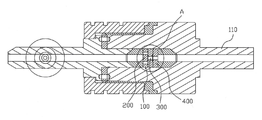
도 4는 본 발명에 따른 고압력 호모게나이저용 분사 모듈이 적용된 상태의 단면도이며,
도 5는 도 4의 A부 확대도이고,
도 6은 본 발명의 다른 실시예를 설명하기 위한 분사 모듈의 부분 정면도이다.FIG. 1 is a perspective view showing an example of a conventional high-pressure homogenizer,
2 is a cross-sectional view showing an example of a conventional injection module for a high-pressure homogenizer,
3 is a schematic exploded perspective view of the injection module for a high-pressure homogenizer according to the present invention,
4 is a cross-sectional view of the injection module for a high-pressure homogenizer according to the present invention,
Fig. 5 is an enlarged view of part A in Fig. 4,
6 is a partial front view of the injection module for explaining another embodiment of the present invention.
본 발명에 따른 고압력 호모게나이저용 분사 모듈(100)은 중앙이 관통된 원통형 실린더(110)와 상기 실린더(110)의 중간에 결합되어 분사로를 형성하는 제1 노즐 블록(200), 제2 노즐 블럭(300) 및 제3 노즐 블럭(400)으로 구성되고; 제1 노즐 블록(200)은 측면 원의 반지름 중간을 중심으로 하는 제1원형공(210)이 블록의 양측면을 관통하여 동일 지름선상에 두 개 형성되어지며, 측면 원의 반지름 중간을 중심으로 하고 제1원형공(210)이 형성된 지름선과 직각의 지름선상에 제1 원형 요홈(220)이 형성되어지고, 측면 원의 중심으로 하고 제1원형공(210) 또는 제1 원형 요홈(220)의 지름에 두배의 지름을 갖는 제2 원형 요홈(250)이 형성되며 제1원형공(210)과 제2 원형 요홈(250) 사이 및 제2 원형 요홈(250)과 제1 원형 요홈(220) 사이에 미세홈(230, 240)이 형성되어지되 넓이가 다른 제1 미세홈(230) 및 제2 미세홈(240)이 형성되며; 제2 노즐 블럭(300)은 제1 노즐 블록(200)의 제1 원형 요홈(210) 동일한 지름의 제2원형공(310)이 관통 형성되고, 제2원형공(310)의 지름과 동일한 두께를 갖는 환형 요홈(330)이 형성되며, 측면 원의 중심에 제2 원형 요홈(320)이 형성되고, 환형 요홈(330)과 제2 원형 요홈(320) 사이에 제3 미세홈(340)이 형성되며; 제3 노즐 블록(400)은 제2 원형 요홈(320)과 동일한 지름으로 제3 원형공(410)이 관통 형성되고, 제1 노즐 블록(200), 제2 노즐 블럭(300) 및 제3 노즐 블록(400)이 밀착되어 결합 구성된 것으로 특징지워진다.The
상기 제1 노즐 블록(200), 제2 노즐 블럭(300) 및 제3 노즐 블록(400)은 각각 강도가 높은 재질로 구성되는 표층(미도시)과 표층을 지지하는 지지층(미도시)으로 구성되고, 표층의 재질로는 다이아몬드, 지지층의 재질은 스테인레스 스틸인 것이 바람직하지만 반드시 이에 한정되는 것은 아니고, 강도가 높은 재질이라면 모두 사용 가능하며, 특히 표층은 지지층 보다 강도가 우수하여야 한다.The
특히, 표층에는 미세홈에 의한 유로가 형성되기 때문에 표층의 두께가 형성되는 유로의 높이 보다 두껍게 구성되는 것이 가공의 용이성 및 사용시 오염 방지 측면에서 바람직하지만 표층은 강도가 우수한 재질을 사용하여야 하기 때문에 가격 상승 요인이 되기 때문에 표층을 너무 두껍게 형성하지 않도록 하는 것이 효과적이다. 본 발명에서는 표층의 두께를 3㎜로 하였다.Particularly, since a channel is formed in the surface layer by the fine grooves, it is preferable that the thickness of the surface layer is made larger than the height of the channel in which the surface layer is formed in view of ease of processing and prevention of contamination during use. However, It is effective to prevent the surface layer from being formed too thick. In the present invention, the thickness of the surface layer is 3 mm.
그러나, 상기의 제1 노즐 블록(200), 제2 노즐 블럭(300)과 제3 노즐 블록(400)은 표층과 지지층으로 적층 구성되지 않고 강도가 우수한 재질을 이용하여 하나의 층으로 구성할 수도 있다.However, the
상기 제1 노즐 블록(200)은 도 3 내지 도 6에 도시된 바와 같이 측면 원의 반지름 중간을 중심으로 하는 제1원형공(210)이 블록의 양측면을 관통하여 동일 지름선상에 두 개 형성되어지며, 측면 원의 반지름 중간을 중심으로 하고 제1원형공(210)이 형성된 지름선과 직각의 지름선상에 제1 원형 요홈(220)이 형성되어지고, 측면 원의 중심으로 하고 제1원형공(210) 또는 제1 원형 요홈(220)의 지름에 두배의 지름을 갖는 제2 원형 요홈(250)이 형성되며 제1원형공(210)과 제2 원형 요홈(250) 사이 및 제2 원형 요홈(250)과 제1 원형 요홈(220) 사이에 미세홈(230, 240)이 형성되어지되 넓이가 다른 제1 미세홈(230) 및 제2 미세홈(240)이 형성된다.As shown in FIGS. 3 to 6, the
상기 각각 두 개의 제1원형공(210)과 제1 원형 요홈(220)의 지름은 동일한 것이 제작의 용이성 및 정확한 균형 유지 측면에서 바람직하지만, 다르게 형성할 수 도 있고, 다르게 형성할 경우에는 제1원형공(210)의 지름을 제1 원형 요홈(220)의 지름 보다 크게 형성하는 것이 유체의 효과적인 흐름 측면에서 바람직이다.The two first
한편, 상기 제1원형공(210)과 제2 원형 요홈(250) 사이 및 제2 원형 요홈(250)과 제1 원형 요홈(220) 사이에 형성되는 제1 미세홈(230) 및 제2 미세홈(240)은 제2 원형 요홈(250)의 원형이 완전히 상실되지 않도록 형성하는 것이 우수한 난류 또는 와류 현상 유발, 전단력, 충격 및 공동화 현상 측면에서 효과적이다.The first
본 발명에서는 일예로 제1 노즐 블록(200)의 측면원 지름을 8㎜, 제1원형공(210)과 제1 원형 요홈(220)의 반지름을 0.5㎜, 제1 원형 요홈(220), 제1 미세홈(230) 및 제2 미세홈(240)과 제2 원형 요홈(250)의 높이를 1 ∼ 3㎜로 행하였다.In the present invention, the
상기 제1 미세홈(230) 및 제2 미세홈(240)은 넓이가 다르게 형성하되 제1 미세홈(230)의 넓이가 제2 미세홈(240)의 넓이 보다 크도록 형성하여 2단계에 걸쳐 분산이 이루어지도록 한다.The first micro-grooves 230 and the second micro-grooves 240 are formed to have different widths, and the width of the first micro-grooves 230 is greater than the width of the second micro-grooves 240, So that dispersion is achieved.
본 발명에서는 일례로 제1 미세홈(230)의 넓이를 200㎛, 제2 미세홈(240)의 넓이를 150㎛로 제작하였다.In the present invention, for example, the width of the first
또한, 상기 제2 노즐 블럭(300)에는 제1 노즐 블록(200)의 제1 원형 요홈(220)과 동일한 지름의 제2원형공(310)이 관통 형성되고, 제2원형공(310)의 지름과 동일한 두께를 갖는 환형 요홈(330)이 형성되며, 측면 원의 중심에 제2 원형 요홈(320)이 형성되고, 환형 요홈(330)과 제2 원형 요홈(320) 사이에 제3 미세홈(340)이 형성된다.A second
상기 제2 원형 요홈(320)의 지름은 환형 요홈(330)의 내측 지름 보다 작도록 하여 제3 미세홈(340)이 형성 가능하도록 하며, 제3 미세홈(340)의 넓이는 제2 미세홈(240)의 넓이 보다 작도록 형성하고, 본 발명에서는 제3 미세홈(340)의 넓이를 75㎛로 제작하였다.The diameter of the second
한편, 상기 제1 노즐 블록(200)의 제1 원형 요홈(220)과 제2 노즐 블럭(300)의 제2원형공(310)이 정확하게 일치하도록 설치되어야 고압에 의한 손상이 방지되지만 설치시 제1 원형 요홈(220)과 제2원형공(310)을 정확하게 일치시켜 설치하는 것이 용이하지는 않다.Meanwhile, the first
따라서, 도 6에 도시된 바와 같이 제2 노즐 블럭(300)의 제2원형공(310)을 원형이 아닌 타원형으로 형성하여 제1 노즐 블록(200)의 제1 원형 요홈(220)과 제2 노즐 블럭(300)의 제2원형공(310)이 정확하게 일치하게 설치되지 않더라도 고압에 의한 손상이 방지되도록 하였다.6, the second
그러나, 상기 제2 노즐 블럭(300)의 제2원형공(310)이 원형이 아닌 타원형으로 형성되더라도 타원의 중심이 제1 노즐 블록(200)의 제1 원형 요홈(220) 중심과 일치되도록 설치하는 것이 바람직하다.However, even if the second
한편, 상기 제3 노즐 블록(400)은 제2 원형 요홈(320)과 동일한 지름으로 제3 원형공(410)이 관통 형성되어 설치시 제2 노즐 블록(300)에 형성된 패턴이 기능을 발휘하도록 한다.The
상기와 같이 구성되는 분사 모듈이 적용되는 본 발명에 따른 고압력 호모게나이저의 작동을 살펴보면 다음과 같다.The operation of the high-pressure homogenizer according to the present invention to which the above-described injection module is applied will be described below.
분사 모듈의 좌측 유입구로 고압의 유체가 유입되고, 제1 노즐 블록(200), 제2 노즐 블럭(300)과 제3 노즐 블록(400)을 통과하여 우측으로 이송되게 된다. 특히, 제1 노즐 블록(200)과 제2 노즐 블럭(300)을 통과시 유체는 제1원형공(210), 제1 미세홈(230), 제2 원형 요홈(250), 제2 미세홈(240), 제1 원형 요홈(220), 제2원형공(310), 환형요홈(330), 제3 미세홈(340), 제2 원형요홈(320)을 순차적으로 통과하게 되면서 강하게 회전을 하게 될 뿐만 아니라 베르누이 정리의 원리에 따라 전단력(shear), 난류 또는 와류(turbulence) 현상, 충격(impact), 공동화(cavitation) 현상이 발생하게 되어 분산 효과가 발현되고 유체의 에멀션화가 이루어지게 된다.The high pressure fluid flows into the left inlet port of the injection module and is conveyed to the right through the
즉, 본 발명에서는 하나의 분사 모듈을 유체가 통과하면서 3단계에 걸쳐 미세 입자의 파쇄를 행함으로써 분사 모듈이 막히지 않는 효과를 얻을 수 있게 된다.
In other words, according to the present invention, it is possible to obtain the effect that the injection module is not blocked by performing the fine particle crushing in three stages while the fluid passes through one injection module.
110. 원통형 실린더 200. 제1 노즐 블록
210. 제1원형공 220. 제1 원형 요홈
230. 제1 미세홈 240. 제2 미세홈
250. 제2 원형 요홈 300. 제2 노즐 블럭
310. 제2원형공 320. 제2 원형 요홈
330. 환형 요홈 340. 제3 미세홈
400. 제3 노즐 블록 410. 제3 원형공110.
210. First
230. First
250. Second
310. Second
330.
400.
Claims (2)
A first nozzle block 200, a second nozzle block 300 and a third nozzle block 400 coupled to the center of the cylinder 110 and the cylinder 110 to form an injection path, Being; In the first nozzle block 200, two first circular holes 210 are formed on the same diameter line passing through both side surfaces of the block, centered on the middle of the radius of the side circle, A first circular groove 220 is formed on a diameter line perpendicular to the diameter line formed with the first circular hole 210 and the center of the first circular hole 210 or the first circular groove 220 A second circular groove 250 having a diameter equal to twice the diameter is formed and is formed between the first circular hole 210 and the second circular groove 250 and between the second circular groove 250 and the first circular groove 220 The first micro-grooves 230 and the second micro-grooves 240 having different widths are formed in the micro-grooves 230 and 240, respectively; The second nozzle block 300 includes a second circular hole 310 having the same diameter as that of the first circular groove 210 of the first nozzle block 200. The second circular hole 310 has a thickness equal to the diameter of the second circular hole 310 A second circular groove 320 is formed at the center of the side circle and a third minute groove 340 is formed between the circular groove 330 and the second circular groove 320 / RTI > The third nozzle block 400 has a third circular hole 410 formed therethrough with the same diameter as the second circular groove 320 and has a first nozzle block 200, a second nozzle block 300, And a block (400) are closely coupled to each other to constitute an injection module (100) for a high-pressure homogenizer.
The injection module (100) of claim 1, wherein the second circular hole (310) of the second nozzle block (300) is formed in an oval shape.
Priority Applications (1)
| Application Number | Priority Date | Filing Date | Title |
|---|---|---|---|
| KR20130103528A KR20150025653A (en) | 2013-08-29 | 2013-08-29 | The injection module for high pressure homogenizer |
Applications Claiming Priority (1)
| Application Number | Priority Date | Filing Date | Title |
|---|---|---|---|
| KR20130103528A KR20150025653A (en) | 2013-08-29 | 2013-08-29 | The injection module for high pressure homogenizer |
Related Child Applications (1)
| Application Number | Title | Priority Date | Filing Date |
|---|---|---|---|
| KR1020150115236A Division KR102052231B1 (en) | 2015-08-17 | 2015-08-17 | The injection module for high pressure homogenizer |
Publications (1)
| Publication Number | Publication Date |
|---|---|
| KR20150025653A true KR20150025653A (en) | 2015-03-11 |
Family
ID=53021831
Family Applications (1)
| Application Number | Title | Priority Date | Filing Date |
|---|---|---|---|
| KR20130103528A Ceased KR20150025653A (en) | 2013-08-29 | 2013-08-29 | The injection module for high pressure homogenizer |
Country Status (1)
| Country | Link |
|---|---|
| KR (1) | KR20150025653A (en) |
Cited By (1)
| Publication number | Priority date | Publication date | Assignee | Title |
|---|---|---|---|---|
| CN114225804A (en) * | 2021-09-30 | 2022-03-25 | 上海迈克孚生物科技有限公司 | Nano material dispersion mixing processor |
-
2013
- 2013-08-29 KR KR20130103528A patent/KR20150025653A/en not_active Ceased
Cited By (1)
| Publication number | Priority date | Publication date | Assignee | Title |
|---|---|---|---|---|
| CN114225804A (en) * | 2021-09-30 | 2022-03-25 | 上海迈克孚生物科技有限公司 | Nano material dispersion mixing processor |
Similar Documents
| Publication | Publication Date | Title |
|---|---|---|
| JP5032703B2 (en) | Apparatus for mixing liquids by generating shear forces and / or cavitation | |
| US9931601B2 (en) | Venturi bypass system and associated methods | |
| US20150173322A1 (en) | Homogenizer valve | |
| KR101043895B1 (en) | Injection module for high pressure homogenizer | |
| US2882025A (en) | Homogenizing valve | |
| CN102309932B (en) | Gas liquid mixing apparatus and application method thereof | |
| CN108778478A (en) | Device and method for the particle in dispersing fluid | |
| US12036520B2 (en) | Apparatus for dispersing particles in a liquid | |
| CA2951842C (en) | Interaction chambers with reduced cavitation | |
| KR20150101973A (en) | The injection module for high pressure homogenizer | |
| EP2135667A1 (en) | Cavitator | |
| KR20150025653A (en) | The injection module for high pressure homogenizer | |
| JPWO2016035704A1 (en) | Seawater desalination system and energy recovery device | |
| EP3007811B1 (en) | Apparatus, system, and methods for blending crude oils | |
| CN111093816B (en) | Liquid mixture nozzle, flow system and method for dispersing particles in a liquid mixture | |
| JP5654291B2 (en) | Static fluid mixing device | |
| CN203790842U (en) | Vertical liquid static mixer | |
| CN219765026U (en) | High-pressure homogenizing device | |
| US11666871B2 (en) | Mixing head | |
| CN201415111Y (en) | Visbreaking, antiscale and average mixing device for raw oil mixed solution | |
| CN204619780U (en) | A kind of negative pressure jet flow pipe-line mixer | |
| CN100443152C (en) | Flow diversion structure of high pressure homogenization device | |
| CN224024731U (en) | A Y-type homogeneous cavity valve core structure | |
| CN206477810U (en) | A kind of ejector mixing | |
| CN101906316A (en) | Viscosity-reducing and scale-controlling uniform mixing method for crude oil mixed liquor and viscosity-reducing and scale-controlling uniform mixer thereof |
Legal Events
| Date | Code | Title | Description |
|---|---|---|---|
| A201 | Request for examination | ||
| PA0109 | Patent application |
Patent event code: PA01091R01D Comment text: Patent Application Patent event date: 20130829 |
|
| PA0201 | Request for examination | ||
| E902 | Notification of reason for refusal | ||
| PE0902 | Notice of grounds for rejection |
Comment text: Notification of reason for refusal Patent event date: 20141224 Patent event code: PE09021S01D |
|
| PG1501 | Laying open of application | ||
| E601 | Decision to refuse application | ||
| PE0601 | Decision on rejection of patent |
Patent event date: 20150717 Comment text: Decision to Refuse Application Patent event code: PE06012S01D Patent event date: 20141224 Comment text: Notification of reason for refusal Patent event code: PE06011S01I |
|
| A107 | Divisional application of patent | ||
| PA0107 | Divisional application |
Comment text: Divisional Application of Patent Patent event date: 20150817 Patent event code: PA01071R01D |