KR20140140744A - Battery module - Google Patents
Battery module Download PDFInfo
- Publication number
- KR20140140744A KR20140140744A KR1020130061498A KR20130061498A KR20140140744A KR 20140140744 A KR20140140744 A KR 20140140744A KR 1020130061498 A KR1020130061498 A KR 1020130061498A KR 20130061498 A KR20130061498 A KR 20130061498A KR 20140140744 A KR20140140744 A KR 20140140744A
- Authority
- KR
- South Korea
- Prior art keywords
- region
- bus bar
- hole
- terminal portion
- terminal
- Prior art date
- Legal status (The legal status is an assumption and is not a legal conclusion. Google has not performed a legal analysis and makes no representation as to the accuracy of the status listed.)
- Ceased
Links
- 230000035515 penetration Effects 0.000 claims description 51
- 238000005452 bending Methods 0.000 claims description 12
- 230000000149 penetrating effect Effects 0.000 claims description 11
- 238000000034 method Methods 0.000 claims 19
- 230000008878 coupling Effects 0.000 description 4
- 238000010168 coupling process Methods 0.000 description 4
- 238000005859 coupling reaction Methods 0.000 description 4
- PXHVJJICTQNCMI-UHFFFAOYSA-N Nickel Chemical compound [Ni] PXHVJJICTQNCMI-UHFFFAOYSA-N 0.000 description 2
- 239000000470 constituent Substances 0.000 description 2
- 239000008151 electrolyte solution Substances 0.000 description 2
- 230000004048 modification Effects 0.000 description 2
- 238000012986 modification Methods 0.000 description 2
- RYGMFSIKBFXOCR-UHFFFAOYSA-N Copper Chemical compound [Cu] RYGMFSIKBFXOCR-UHFFFAOYSA-N 0.000 description 1
- BQCADISMDOOEFD-UHFFFAOYSA-N Silver Chemical compound [Ag] BQCADISMDOOEFD-UHFFFAOYSA-N 0.000 description 1
- 238000006243 chemical reaction Methods 0.000 description 1
- 239000004020 conductor Substances 0.000 description 1
- 238000010276 construction Methods 0.000 description 1
- 229910052802 copper Inorganic materials 0.000 description 1
- 239000010949 copper Substances 0.000 description 1
- 238000007599 discharging Methods 0.000 description 1
- PCHJSUWPFVWCPO-UHFFFAOYSA-N gold Chemical compound [Au] PCHJSUWPFVWCPO-UHFFFAOYSA-N 0.000 description 1
- 229910052737 gold Inorganic materials 0.000 description 1
- 239000010931 gold Substances 0.000 description 1
- 239000002184 metal Substances 0.000 description 1
- 229910052751 metal Inorganic materials 0.000 description 1
- 229910052759 nickel Inorganic materials 0.000 description 1
- 239000011255 nonaqueous electrolyte Substances 0.000 description 1
- 229910052709 silver Inorganic materials 0.000 description 1
- 239000004332 silver Substances 0.000 description 1
- 125000006850 spacer group Chemical group 0.000 description 1
Images


Classifications
-
- H—ELECTRICITY
- H01—ELECTRIC ELEMENTS
- H01M—PROCESSES OR MEANS, e.g. BATTERIES, FOR THE DIRECT CONVERSION OF CHEMICAL ENERGY INTO ELECTRICAL ENERGY
- H01M50/00—Constructional details or processes of manufacture of the non-active parts of electrochemical cells other than fuel cells, e.g. hybrid cells
- H01M50/50—Current conducting connections for cells or batteries
- H01M50/543—Terminals
- H01M50/564—Terminals characterised by their manufacturing process
- H01M50/567—Terminals characterised by their manufacturing process by fixing means, e.g. screws, rivets or bolts
-
- H—ELECTRICITY
- H01—ELECTRIC ELEMENTS
- H01M—PROCESSES OR MEANS, e.g. BATTERIES, FOR THE DIRECT CONVERSION OF CHEMICAL ENERGY INTO ELECTRICAL ENERGY
- H01M50/00—Constructional details or processes of manufacture of the non-active parts of electrochemical cells other than fuel cells, e.g. hybrid cells
- H01M50/20—Mountings; Secondary casings or frames; Racks, modules or packs; Suspension devices; Shock absorbers; Transport or carrying devices; Holders
- H01M50/204—Racks, modules or packs for multiple batteries or multiple cells
- H01M50/207—Racks, modules or packs for multiple batteries or multiple cells characterised by their shape
- H01M50/209—Racks, modules or packs for multiple batteries or multiple cells characterised by their shape adapted for prismatic or rectangular cells
-
- H—ELECTRICITY
- H01—ELECTRIC ELEMENTS
- H01M—PROCESSES OR MEANS, e.g. BATTERIES, FOR THE DIRECT CONVERSION OF CHEMICAL ENERGY INTO ELECTRICAL ENERGY
- H01M50/00—Constructional details or processes of manufacture of the non-active parts of electrochemical cells other than fuel cells, e.g. hybrid cells
- H01M50/50—Current conducting connections for cells or batteries
- H01M50/502—Interconnectors for connecting terminals of adjacent batteries; Interconnectors for connecting cells outside a battery casing
- H01M50/503—Interconnectors for connecting terminals of adjacent batteries; Interconnectors for connecting cells outside a battery casing characterised by the shape of the interconnectors
-
- H—ELECTRICITY
- H01—ELECTRIC ELEMENTS
- H01M—PROCESSES OR MEANS, e.g. BATTERIES, FOR THE DIRECT CONVERSION OF CHEMICAL ENERGY INTO ELECTRICAL ENERGY
- H01M50/00—Constructional details or processes of manufacture of the non-active parts of electrochemical cells other than fuel cells, e.g. hybrid cells
- H01M50/50—Current conducting connections for cells or batteries
- H01M50/543—Terminals
- H01M50/547—Terminals characterised by the disposition of the terminals on the cells
- H01M50/55—Terminals characterised by the disposition of the terminals on the cells on the same side of the cell
-
- H—ELECTRICITY
- H01—ELECTRIC ELEMENTS
- H01M—PROCESSES OR MEANS, e.g. BATTERIES, FOR THE DIRECT CONVERSION OF CHEMICAL ENERGY INTO ELECTRICAL ENERGY
- H01M50/00—Constructional details or processes of manufacture of the non-active parts of electrochemical cells other than fuel cells, e.g. hybrid cells
- H01M50/50—Current conducting connections for cells or batteries
- H01M50/543—Terminals
- H01M50/552—Terminals characterised by their shape
- H01M50/553—Terminals adapted for prismatic, pouch or rectangular cells
-
- H—ELECTRICITY
- H01—ELECTRIC ELEMENTS
- H01R—ELECTRICALLY-CONDUCTIVE CONNECTIONS; STRUCTURAL ASSOCIATIONS OF A PLURALITY OF MUTUALLY-INSULATED ELECTRICAL CONNECTING ELEMENTS; COUPLING DEVICES; CURRENT COLLECTORS
- H01R11/00—Individual connecting elements providing two or more spaced connecting locations for conductive members which are, or may be, thereby interconnected, e.g. end pieces for wires or cables supported by the wire or cable and having means for facilitating electrical connection to some other wire, terminal, or conductive member, blocks of binding posts
- H01R11/11—End pieces or tapping pieces for wires, supported by the wire and for facilitating electrical connection to some other wire, terminal or conductive member
- H01R11/28—End pieces consisting of a ferrule or sleeve
- H01R11/281—End pieces consisting of a ferrule or sleeve for connections to batteries
- H01R11/288—Interconnections between batteries
-
- H—ELECTRICITY
- H01—ELECTRIC ELEMENTS
- H01R—ELECTRICALLY-CONDUCTIVE CONNECTIONS; STRUCTURAL ASSOCIATIONS OF A PLURALITY OF MUTUALLY-INSULATED ELECTRICAL CONNECTING ELEMENTS; COUPLING DEVICES; CURRENT COLLECTORS
- H01R4/00—Electrically-conductive connections between two or more conductive members in direct contact, i.e. touching one another; Means for effecting or maintaining such contact; Electrically-conductive connections having two or more spaced connecting locations for conductors and using contact members penetrating insulation
- H01R4/28—Clamped connections, spring connections
- H01R4/48—Clamped connections, spring connections utilising a spring, clip, or other resilient member
-
- Y—GENERAL TAGGING OF NEW TECHNOLOGICAL DEVELOPMENTS; GENERAL TAGGING OF CROSS-SECTIONAL TECHNOLOGIES SPANNING OVER SEVERAL SECTIONS OF THE IPC; TECHNICAL SUBJECTS COVERED BY FORMER USPC CROSS-REFERENCE ART COLLECTIONS [XRACs] AND DIGESTS
- Y02—TECHNOLOGIES OR APPLICATIONS FOR MITIGATION OR ADAPTATION AGAINST CLIMATE CHANGE
- Y02E—REDUCTION OF GREENHOUSE GAS [GHG] EMISSIONS, RELATED TO ENERGY GENERATION, TRANSMISSION OR DISTRIBUTION
- Y02E60/00—Enabling technologies; Technologies with a potential or indirect contribution to GHG emissions mitigation
- Y02E60/10—Energy storage using batteries
Landscapes
- Chemical & Material Sciences (AREA)
- Chemical Kinetics & Catalysis (AREA)
- Electrochemistry (AREA)
- General Chemical & Material Sciences (AREA)
- Engineering & Computer Science (AREA)
- Manufacturing & Machinery (AREA)
- Connection Of Batteries Or Terminals (AREA)
- Battery Mounting, Suspending (AREA)
Abstract
본 발명은 배터리 모듈에 관한 것으로, 일 방향으로 정렬되되, 각각 일면에 단자부를 구비하는 복수의 배터리셀, 서로 다른 상기 배터리셀의 상기 단자부 간을 전기적으로 연결하되, 상기 서로 다른 배터리셀의 상기 단자부가 각각 관통되는 관통영역, 및 상기 관통영역 간을 연결하는 연결영역을 포함하는 버스바를 포함하고, 상기 관통영역 각각에는 하나의 상기 단자부가 관통되는 2개 이상의 관통홀이 대응되게 형성되며, 상기 버스바는 상기 단자부에 억지끼움됨으로써, 별도의 고정부재 없이 단자부에 대한 버스바의 이탈을 방지하는 배터리 모듈을 제공한다.The present invention relates to a battery module, comprising: a plurality of battery cells arranged in one direction, each having a terminal portion on one side thereof; and electrically connecting the terminal portions of the different battery cells, And a bus bar including a connection region connecting the through regions, wherein each of the through regions is formed with two or more through holes corresponding to one through which the one terminal portion passes, The bar is held in the terminal portion so as to prevent a deviation of the bus bar from the terminal portion without a separate fixing member.
Description
본 발명은 배터리 모듈에 관한 것이다.The present invention relates to a battery module.
최근, 고에너지 밀도의 비수전해액을 이용한 고출력 배터리 모듈이 개발되고 있다. 이러한 고출력 배터리 모듈은 고전력을 필요로 하는 기기, 예를 들어 전기 자동차 등의 모터 구동에 사용될 수 있도록 복수의 배터리셀을 직렬로 연결하여 대용량으로 구현되고 있다.Recently, a high output battery module using a non-aqueous electrolyte having a high energy density has been developed. Such a high output battery module is implemented in a large capacity by connecting a plurality of battery cells in series so that it can be used for driving a motor, such as an electric vehicle, which requires high power.
이러한 배터리 모듈을 채용하는 기기들이 늘어나면서 배터리 모듈의 생산성 향상에 대한 연구가 진행되고 있으며, 기기들의 외관이 다양해지면서 이에 대응하여 배터리 모듈의 형태도 다양할 것이 요구되고 있다. 단, 배터리 모듈은 기본적으로 안전성이 전제되어야 하는바, 이를 모두 충족시킬 수 있는 배터리 모듈의 구조에 대한 연구가 다방면으로 진행되고 있다.As the number of devices employing such battery modules is increasing, studies are being conducted to improve the productivity of the battery module, and as the appearance of the devices is diversified, it is required that the form of the battery module is also diversified corresponding thereto. However, since the safety of the battery module is basically required, studies on the structure of the battery module capable of satisfying all of them have been carried out in various fields.
한편, 복수의 배터리셀을 연결하는 부재로서 버스바가 이용되고 있는데, 종래의 버스바의 경우 단자부에 대한 이탈을 방지하기 위해 볼트나 너트 등의 별도의 고정부재를 이용하고 있어 비효율적인 문제점이 있다.On the other hand, a bus bar is used as a member for connecting a plurality of battery cells. However, in the case of a conventional bus bar, a separate fixing member such as a bolt or a nut is used to prevent detachment of the terminal portion.
본 발명은 별도의 고정부재 없이도 단자부에 고정될 수 있는 버스바를 제공하기 위한 것이다.The present invention is to provide a bus bar that can be fixed to a terminal portion without a separate fixing member.
본 발명의 실시예에 따른 배터리 모듈은, 일 방향으로 정렬되되, 각각 일면에 단자부를 구비하는 복수의 배터리셀, 서로 다른 상기 배터리셀의 상기 단자부 간을 전기적으로 연결하되, 상기 서로 다른 배터리셀의 상기 단자부가 각각 관통되는 관통영역, 및 상기 관통영역 간을 연결하는 연결영역을 포함하는 버스바를 포함하고, 상기 관통영역 각각에는 하나의 상기 단자부가 관통되는 2개 이상의 관통홀이 대응되게 형성되며, 상기 버스바는 상기 단자부에 억지끼움될 수 있다.A battery module according to an exemplary embodiment of the present invention includes a plurality of battery cells arranged in one direction and each having a terminal portion on one surface thereof and a plurality of terminal portions electrically connected to the terminal portions of the different battery cells, And a bus bar including a through region through which the terminal portion passes, and a connecting region connecting the through regions, wherein each of the through regions has two or more through holes corresponding to one through which the one terminal portion passes, The bus bar may be forcedly inserted into the terminal portion.
또한, 상기 연결영역은 절곡부를 구비하여 상기 버스바에 장력을 제공하고, 상기 버스바는 상기 장력에 의해 상기 단자부에 고정될 수 있다.The connection region may include a bent portion to provide tension to the bus bar, and the bus bar may be fixed to the terminal portion by the tension.
또한, 상기 관통홀은 상기 버스바의 외측 방향으로 상기 단자부를 미는 힘을 가할 수 있다.In addition, the through hole may exert a pushing force on the terminal portion in an outward direction of the bus bar.
또한, 상기 관통영역은, 상기 연결영역으로부터 연장되되, 상기 단자부가 관통되는 제1 관통홀이 형성된 제1 관통영역, 상기 제1 관통영역으로부터 절곡되어 연장되는 지지영역, 및 상기 지지영역으로부터 절곡되어 연장되되, 상기 제1 관통홀을 관통한 상기 단자부가 관통되는 제2 관통홀이 형성된 제2 관통영역을 포함할 수 있다.The penetrating region may include a first penetrating region extending from the connecting region and having a first penetrating hole penetrating the terminal portion, a supporting region extending from the first penetrating region and extending from the first penetrating region, And a second through region extending through the first through hole and having a second through hole through which the terminal portion penetrates.
또한, 상기 복수의 배터리셀의 단자부가 구비된 면을 덮되, 상기 절곡부에 대응되는 위치에 리브를 구비하여 상기 버스바의 이탈을 방지하는 커버부재를 더 포함할 수 있다.The battery pack may further include a cover member covering the surface of the plurality of battery cells and having a rib at a position corresponding to the bent portion to prevent the bus bar from being separated.
또한, 상기 제1 관통홀 및 상기 제2 관통홀은 중심이 어긋나게 형성될 수 있다.The first through holes and the second through holes may be shifted from each other in the center.
또한, 상기 지지영역에는 상기 단자부를 향해 돌출된 돌출부가 구비되고, 상기 돌출부는 상기 버스바의 내측 방향으로 상기 단자부를 미는 힘을 가할 수 있다.In addition, the support region may have a protruding portion protruding toward the terminal portion, and the protruding portion may exert a pushing force on the terminal portion in an inner direction of the bus bar.
또한, 상기 버스바의 내측에 상기 버스바와 상기 단자부를 사이에 두고 설치되는 보조 버스바를 더 포함할 수 있다.The bus bar may further include an auxiliary bus bar disposed inside the bus bar with the bus bar and the terminal portion interposed therebetween.
또한, 상기 보조 버스바는 보조 절곡부를 구비하여, 상기 보조 버스바에 장력을 제공하여 상기 보조 버스바의 외측 방향으로 상기 단자부를 미는 힘을 가할 수 있다.The auxiliary bus bar may include an auxiliary bending portion to apply a tension to the auxiliary bus bar to exert a pressing force on the terminal portion in an outward direction of the auxiliary bus bar.
또한, 상기 연결영역은 상기 제1 관통영역으로부터 연장되는 제1 연결영역 및 상기 제2 관통영역으로부터 연장되는 제2 연결영역을 포함하고, 상기 제1 연결영역 및 상기 제2 연결영역 각각에는 절곡부가 구비될 수 있다.The connection region may include a first connection region extending from the first penetration region and a second connection region extending from the second penetration region, and each of the first connection region and the second connection region may include a bent portion .
또한, 상기 제1 연결영역의 절곡부와 상기 제2 연결영역의 절곡부는 서로 반대 방향을 향해 돌출될 수 있다.The bending portion of the first connection region and the bending portion of the second connection region may protrude in directions opposite to each other.
또한, 상기 제1 관통영역의 상기 제1 관통홀의 외측부에는 상기 단자부의 측면에 접촉하여 상기 단자부를 상기 버스바의 내측 방향으로 미는 힘을 가하는 제1 지지부가 구비되고, 상기 제2 관통영역의 상기 제2 관통홀의 내측부에는 상기 단자부의 측면에 접촉하여 상기 단자부를 상기 버스바의 외측 방향으로 미는 힘을 가하는 제2 지지부가 구비될 수 있다.In addition, the first through-hole of the first through-hole is provided with a first supporting portion contacting the side surface of the terminal portion to apply a force to push the terminal portion inward of the bus bar, And a second support portion for contacting the side surface of the terminal portion and applying a force to push the terminal portion in an outward direction of the bus bar may be provided on the inner side of the second through hole.
또한, 상기 관통영역은 하나의 단자부가 관통되는 3개의 관통홀이 대응되게 형성될 수 있다.Also, the through-hole may have three through-holes corresponding to one through-hole.
또한, 상기 관통영역은, 상기 복수의 배터리셀 중 어느 하나의 배터리셀의 단자부가 관통되는 A 관통영역 및 상기 어느 하나의 배터리셀에 인접한 배터리셀의 단자부가 관통되는 B 관통영역을 포함하고, 상기 연결영역은 A 관통영역 및 B 관통영역 간을 연결할 수 있다.The penetrating region may include an A-passing region through which a terminal portion of one of the plurality of battery cells penetrates, and a B-passing region through which a terminal portion of the battery cell adjacent to the one battery cell penetrates, The connection area can connect the A through area and the B through area.
또한, 상기 A 관통영역 및 상기 B 관통영역은 각각 제1 관통홀이 형성된 제1 관통영역, 제2 관통홀이 형성된 제2 관통영역, 및 제3 관통홀이 형성된 제3 관통영역을 포함하고, 상기 연결영역은 상기 A 관통영역 및 B 관통영역의 상기 제1 관통영역 간을 연결하는 제1 연결영역, 상기 제2 관통영역 간을 연결하는 제2 연결영역, 및 상기 제3 관통영역 간을 연결하는 제3 연결영역을 포함할 수 있다.The A through region and the B through region each include a first through region formed with a first through hole, a second through region formed with a second through hole, and a third through region formed with a third through hole, Wherein the connection region includes a first connection region connecting the first through regions of the A through region and the B through region, a second connection region connecting the second through regions, and a second connection region connecting the third through regions, And a second connection area for connecting the first connection area and the second connection area.
또한, 상기 버스바는, A 관통영역의 제1 관통영역, 상기 제1 연결영역, 상기 B 관통영역의 제1 관통영역, 상기 B 관통영역의 제2 관통영역, 상기 제2 연결영역, 상기 A 관통영역의 제2 관통영역, 상기 A 관통영역의 제3 관통영역, 상기 제3 연결영역, 및 상기 B 관통영역의 제3 관통영역의 순서대로 연장될 수 있다.The bus bar may include a first through-hole area of the A through-hole area, a first through-hole area of the first connecting area, the B through area, a second through area of the B through area, The third penetration area of the penetration area, the third penetration area of the A penetration area, the third connection area, and the third penetration area of the B penetration area.
또한, 상기 버스바는 일체로 연장된 S자 형상을 이룰 수 있다.Further, the bus bar may have an S-shaped configuration extending in one piece.
또한, 상기 제1 관통영역 및 제3 관통영역의 내측부에는 지지부가 구비되고, 상기 지지부는 상기 단자부를 상기 버스바의 외측 방향으로 미는 힘을 가할 수 있다.In addition, a support portion may be provided on the inner side of the first through-hole and the third through-hole, and the supporting portion may apply a force to push the terminal portion in the outward direction of the bus bar.
또한, 상기 단자부와 상기 관통홀은 후크 구조에 의해 결합될 수 있다.The terminal portion and the through hole may be coupled by a hook structure.
또한, 상기 단자부에는 후크홈이 형성되고, 상기 버스바의 상기 제1 관통영역에 형성된 상기 제1 관통홀은 상기 후크홈에 안착되어, 상기 버스바는 상기 단자부와 후크 결합될 수 있다.
The terminal portion may be formed with a hook groove, and the first through hole formed in the first through region of the bus bar may be seated in the hook groove, and the bus bar may be hooked to the terminal portion.
본 발명의 특징 및 이점들은 첨부도면에 의거한 다음의 상세한 설명으로부터 더욱 명백해질 것이다.The features and advantages of the present invention will become more apparent from the following detailed description based on the accompanying drawings.
이에 앞서, 본 명세서 및 청구범위에 사용된 용어나 단어는 통상적이고 사전적인 의미로 해석되어서는 아니되며, 발명자가 그 자신의 발명을 가장 최선의 방법으로 설명하기 위해 용어의 개념을 적절하게 정의할 수 있다는 원칙에 입각하여 본 발명의 기술적 사상에 부합되는 의미와 개념으로 해석되어야만 한다.Prior to this, terms and words used in the present specification and claims should not be construed in a conventional and dictionary sense, and the inventor may appropriately define the concept of a term in order to best describe its invention The present invention should be construed in accordance with the spirit and scope of the present invention.
본 발명에 따른 배터리 모듈은 버스바를 단자부에 억지끼움하여 고정하는바, 별도의 고정부재 없이 버스바의 이탈을 방지할 수 있다.In the battery module according to the present invention, the bus bar is fixedly inserted into the terminal portion, and the bus bar can be prevented from being separated without a separate fixing member.
또한, 본 발명에 따르면 버스바의 연결영역에 절곡부를 구비하여 버스바에 장력을 부여함으로써 버스바와 단자부의 결합을 더욱 견고히 할 수 있다.In addition, according to the present invention, a bending portion is provided in a connection region of a bus bar, and a tension is applied to the bus bar, so that the connection between the bus bar and the terminal portion can be further strengthened.
도 1은 본 발명의 일 실시예에 따른 배터리 모듈의 사시도이다.
도 2는 도 1에 도시한 배터리 모듈의 분해사시도이다.
도 3은 도 1에 도시한 배터리 모듈의 버스바의 사시도이다.
도 4는 도 1에 도시한 배터리 모듈의 버스바의 단면도이다.
도 5는 도 1에 도시한 배터리 모듈의 버스바가 단자부에 체결된 모습을 나타낸 단면도이다.
도 6은 도 1에 도시한 배터리 모듈의 단면도이다.
도 7은 본 발명의 다른 실시예에 따른 배터리 모듈의 버스바 및 보조 버스바의 사시도이다.
도 8은 도 7에 도시한 버스바 및 보조 버스바의 단면도이다.
도 9는 도 7에 도시한 버스바 및 보조 버스바가 단자부에 체결된 모습을 나타낸 단면도이다.
도 10은 본 발명의 또 다른 실시예에 따른 배터리 모듈의 버스바의 사시도이다.
도 11은 도 10에 도시한 버스바의 단면도이다.
도 12는 도 10에 도시한 버스바가 단자부에 체결된 모습을 나타낸 단면도이다.
도 13은 본 발명의 또 다른 실시예에 따른 배터리 모듈의 버스바의 사시도이다.
도 14는 도 13에 도시한 버스바의 단면도이다.
도 15는 도 13에 도시한 버스바가 단자부에 체결된 모습을 나타낸 단면도이다.
도 16은 본 발명의 또 다른 실시예에 따른 배터리 모듈의 버스바가 단자부에 체결된 모습을 나타낸 단면도이다.1 is a perspective view of a battery module according to an embodiment of the present invention.
2 is an exploded perspective view of the battery module shown in FIG.
3 is a perspective view of a bus bar of the battery module shown in Fig.
4 is a cross-sectional view of the bus bar of the battery module shown in Fig.
FIG. 5 is a cross-sectional view illustrating a state where a bus bar of the battery module shown in FIG. 1 is fastened to a terminal portion.
6 is a cross-sectional view of the battery module shown in Fig.
7 is a perspective view of a bus bar and an auxiliary bus bar of a battery module according to another embodiment of the present invention.
8 is a cross-sectional view of the bus bar and the auxiliary bus bar shown in Fig.
FIG. 9 is a cross-sectional view showing a state in which the bus bar and the auxiliary bus bar shown in FIG. 7 are fastened to the terminal portions.
10 is a perspective view of a bus bar of a battery module according to another embodiment of the present invention.
11 is a cross-sectional view of the bus bar shown in Fig.
12 is a cross-sectional view showing a state in which the bus bar shown in Fig. 10 is fastened to the terminal portion.
13 is a perspective view of a bus bar of a battery module according to another embodiment of the present invention.
14 is a cross-sectional view of the bus bar shown in Fig.
Fig. 15 is a cross-sectional view showing a state in which the bus bar shown in Fig. 13 is fastened to the terminal portion. Fig.
16 is a cross-sectional view illustrating a state where a bus bar of a battery module according to another embodiment of the present invention is fastened to a terminal portion.
본 발명의 목적, 특정한 장점들 및 신규한 특징들은 첨부된 도면들과 연관되어지는 이하의 상세한 설명과 실시예로부터 더욱 명백해질 것이다. 본 명세서에서 각 도면의 구성요소들에 참조번호를 부가함에 있어서, 동일한 구성 요소들에 한해서는 비록 다른 도면상에 표시되더라도 가능한 한 동일한 번호를 가지도록 하고 있음에 유의하여야 한다. 또한, 제1, 제2 등의 용어는 다양한 구성요소들을 설명하는데 사용될 수 있지만, 상기 구성요소들은 상기 용어들에 의해 한정되어서는 안 된다. 상기 용어들은 하나의 구성요소를 다른 구성요소로부터 구별하는 목적으로만 사용된다. 또한, 본 발명을 설명함에 있어서, 관련된 공지 기술에 대한 구체적인 설명이 본 발명의 요지를 불필요하게 흐릴 수 있다고 판단되는 경우 그 상세한 설명은 생략한다.The objects, specific advantages and novel features of the present invention will become more apparent from the following detailed description and examples taken in conjunction with the accompanying drawings. It should be noted that, in the present specification, the reference numerals are added to the constituent elements of the drawings, and the same constituent elements are assigned the same number as much as possible even if they are displayed on different drawings. Also, the terms first, second, etc. may be used to describe various components, but the components should not be limited by the terms. The terms are used only for the purpose of distinguishing one component from another. In the following description, well-known functions or constructions are not described in detail since they would obscure the invention in unnecessary detail.
이하, 첨부된 도면을 참조하여 본 발명의 실시예를 상세히 설명하기로 한다.
Hereinafter, embodiments of the present invention will be described in detail with reference to the accompanying drawings.
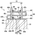
도 1은 본 발명의 일 실시예에 따른 배터리 모듈(100a)의 사시도이고, 도 2는 도 1에 도시한 배터리 모듈(100a)의 분해사시도이다. 이하, 이를 참조하여 본 실시예에 따른 배터리 모듈(100a)에 대해 설명하기로 한다.
FIG. 1 is a perspective view of a
도 1 및 도 2에 도시한 바와 같이, 본 실시예에 따른 배터리 모듈(100a)은 일 방향으로 정렬된 복수의 배터리셀(110), 서로 다른 배터리셀(110)의 단자부(111) 간을 전기적으로 연결하는 버스바(120), 및 단자부(111)가 구비된 배터리셀(110)의 상면(118)을 덮는 커버부재(150)를 포함하며, 별도의 고정부재 없이 버스바(120)를 단자부(111)에 고정할 수 있다.
1 and 2, the
배터리셀(110)은 에너지를 발생하는 부재로서, 복수로 구성되어 일 방향으로 정렬될 수 있다.The
여기서, 각각의 배터리셀(110)은 일면이 개구된 전지케이스와 전지케이스 내에 수납된 전극조립체 및 전해액을 포함할 수 있다. 이때, 전극조립체 및 전해액은 전기화학적으로 반응하여 에너지를 발생할 수 있고, 이러한 전지케이스는 예를 들어 캡 조립체를 포함하는 배터리셀(110)의 상면(118)에 의하여 밀폐될 수 있다. 또한, 배터리셀(110)의 상면(118)에는 서로 다른 극성을 갖는 양극단자(112)와 음극단자(113)를 포함하는 단자부(111)가 돌출되어 구비될 수 있고, 배터리셀(110)의 안전수단으로서 내부에서 발생하는 기체를 외부로 방출하는 통로로 작용하는 벤트부(114)가 더 구비될 수 있다. Here, each of the
한편, 배터리 모듈(100a)은 배터리셀(110)을 일 방향으로 정렬시키기 위하여 고정부(115)를 더 포함할 수 있다. 여기서, 고정부(115)는 배터리셀(110)의 외측에 배치된 한 쌍의 엔드플레이트(116)와 엔드플레이트(116) 간을 연결하는 연결플레이트(117)를 포함할 수 있고, 한 쌍의 엔드플레이트(116) 사이에는 복수의 배터리셀(110)이 정렬될 수 있다. 이때, 배터리셀(110)은 넓은 전면이 서로 대향하도록 나란하게 정렬될 수 있다. 한편, 이러한 고정부(115)는 배터리셀(110)을 안정적으로 고정하기 위함으로, 본 실시예의 형태에 제한되지 않고 다양하게 변형하여 실시할 수 있다. 예를 들어, 배터리셀(110)을 전체적으로 수용하는 하우징의 형태도 고정부(115)에 포함되는 것으로 볼 수 있다. 또한, 배터리셀(110)의 연결 구조 및 배터리셀(110)의 개수는 배터리 모듈(100a)의 설계에 따라 다양하게 변형될 수 있다. 또한, 도 1 및 도 2에서는 인접한 배터리셀(110)이 서로 접촉된 것으로 도시하였으나, 본 발명은 이에 한정되지 않고 배터리셀(110)이 이격되어 위치되거나, 이격된 공간에 스페이서가 구비된 경우도 본 발명에 포함된다 할 것이다.
The
도 3은 도 1에 도시한 배터리 모듈(100a)의 버스바(120)의 사시도이고, 도 4는 도 1에 도시한 배터리 모듈(100a)의 버스바(120)의 단면도이며, 도 5는 도 1에 도시한 배터리 모듈(100a)의 버스바(120)가 단자부(111)에 체결된 모습을 나타낸 단면도이다. 이하, 이를 참조하여 본 실시예에 따른 버스바(120)에 대해 설명하기로 한다.
3 is a perspective view of the
버스바(120)는 서로 다른 배터리셀(110)의 단자부(111)를 상호 전기적으로 연결하는 부재이다.The
여기서, 버스바(120)는 도 2에 도시한 바와 같이 어느 하나의 배터리셀(110)의 양극단자(112)와 인접한 다른 배터리셀(110)의 음극단자(113)를 상호 전기적으로 연결함으로써, 두 배터리셀(110)을 직렬 연결할 수 있다. 또는, 버스바(120)는 어느 하나의 배터리셀(110)의 양극단자(112)와 인접한 다른 배터리셀(110)의 양극단자(112)를, 또는 어느 하나의 배터리셀(110)의 음극단자(113)와 인접한 다른 배터리셀(110)의 음극단자(113)를 상호 전기적으로 연결함으로써, 두 배터리셀(110)을 병렬 연결할 수도 있다. 따라서, 버스바(120)는 단자부(111) 간을 전기적으로 연결할 수 있도록 금, 은, 구리, 니켈 등의 전기전도성 금속으로 구성될 수 있다. 또한, 버스바(120)는 단자부(111)에 대하여 억지끼움 방식으로 결합됨으로써, 너트나 볼트와 같은 다른 고정부재 없이 단자부(111)에 고정될 수 있다.2, the
한편, 버스바(120)는 단자부(111)에 억지끼움될 수 있도록 서로 다른 배터리셀(110)의 단자부(111)가 관통되는 두 관통영역(130), 및 두 관통영역(130) 간을 연결하는 연결영역(140)을 포함할 수 있는데, 이하에서 구체적으로 설명하도록 하겠다.
The
관통영역(130)은 서로 다른 배터리셀(110)의 단자부(111)가 각각 관통되는 영역으로서 버스바(120)의 양측에 각각 구비될 수 있다. 이때, 본 명세서에서는 어느 하나의 배터리셀(110)의 단자부(111)가 관통되는 부분을 A 관통영역(130a), 상기 어느 하나의 배터리셀(110)에 인접한 다른 배터리셀(110)의 단자부(111)가 관통되는 부분을 B 관통영역(130b)이라 하겠다.The through
여기서, 각 관통영역(130)에는 하나의 단자부(111)가 두 개의 관통홀(133, 134)을 관통하도록, 두 개의 관통홀(133, 134)이 복층식으로 대응되게 구비될 수 있다. 구체적으로, 관통영역(130)은 연결영역(140)으로부터 연장되고 제1 관통홀(133)이 형성된 제1 관통영역(131), 제1 관통영역(131)으로부터 절곡되어 연장되고 단자부의 측면을 지지하는 지지영역(135), 및 지지영역(135)으로부터 절곡되어 연장되고 제2 관통홀(134)이 형성된 제2 관통영역(132)을 포함할 수 있다. 따라서, 버스바(120)의 체결시에 단자부(111)는 제2 관통홀(134)을 먼저 통과한 후 제1 관통홀(133)을 통과하여, 두 개의 관통홀(133, 134)에 의해 그 측면을 지지받을 수 있다. 또한, 지지영역(135)은 단자부(111)의 측면에 접촉되어 단자부(111)의 측면을 지지할 수 있다.
Here, two through
연결영역(140)은 서로 다른 배터리셀(110)의 단자부(111)가 관통된 A 관통영역(130a)과 B 관통영역(130b)을 연결하는 영역이다.The
여기서, 연결영역(140)은 관통영역(130)과 일체로 제조될 수 있으며 절곡부(141)를 구비함으로써 버스바(120)에 장력을 제공할 수 있다. 구체적으로, 절곡부(141)는 버스바(120)의 관통영역(130)에 대하여 외측 방향으로 늘어나는 힘을 제공할 수 있고, 이에 따라 단자부(111)와 버스바(120)의 억지끼움은 더욱 견고해질 수 있다. 한편, 도 2 내지 도 5에서는 버스바(120)의 연결영역(140)이 관통영역(130)의 상부(본 실시예에서는 제1 관통영역(131))에서 연결되는 것으로 도시하였으나, 본 발명은 이에 한정되지 않고 버스바(120)의 연결영역(140)이 관통영역(130)의 하부에서 연결되도록 구현되는 것도 가능하다. 즉, 버스바(120)를 반대 방향으로 뒤집어 단자부(111)에 삽입할 수도 있다.
Here, the
한편, 도 4 및 도 5을 참조하여 단자부(111)가 버스바(120)에 억지끼움되는 것을 설명하면 다음과 같다. 4 and 5, a description will be given of the fact that the
도 4에 도시한 바와 같이, 버스바(120)가 단자부(111)로부터 분리되어 있을 때에는, 버스바(120)의 관통영역(130) 중 제2 관통영역(132)이 버스바(120)의 내측으로 다소 당겨진 상태가 될 수 있다. 따라서, 버스바(120)는 전체적으로 약간 휘어진 상태가 될 수 있으며, 이에 따라 제2 관통홀(134)의 내측부(134a)가 제1 관통홀(133)의 내측부(133a)보다 다소 내측에 위치할 수 있다. 즉, 제1 관통홀(133) 및 제2 관통홀(134)의 중심이 어긋난 상태일 수 있다. 여기서, 도 5에 도시한 바와 같이, 버스바(120)의 관통홀(133, 134)에 단자부(111)가 삽입되면, 버스바(120)는 하나의 단자부(111)가 두 개의 관통홀(133, 134)에 삽입될 수 있도록 약간 휘어질 수 있으며, 이에 따라 제2 관통홀(134)의 내측부(134a)가 외측으로 밀리면서 제1 관통홀(133)의 내측부(133a)와 동일 수직선 상에 놓일 수 있다. 이에 따라 제1 관통홀(133)의 내측부(133a) 및 제2 관통홀의 내측부(134a)는 단자부(111)를 버스바(120)의 외측 방향으로 미는 힘을 가할 수 있으며, 지지영역(135)은 단자부(111)를 버스바(120)의 내측 방향으로 미는 힘을 가할 수 있다. 즉, 단자부(111)는 상부 및 하부에서 버스바(120)의 외측을 향하는 힘을, 중간부에서 버스바(120)의 내측을 향하는 힘을 받을 수 있다. 이에 따라 버스바(120)는 단자부(111)에 억지끼움될 수 있고, 별도의 볼트나 너트와 같은 고정부재가 없이도 단자부(111)로부터 쉽게 분리되지 않을 수 있다.
4, when the
도 6은 도 1에 도시한 배터리 모듈(100a)의 단면도이다. 이하, 이를 참조하여 본 실시예에 따른 배터리 모듈(100a)의 커버부재(150)에 대해 설명하기로 한다.6 is a sectional view of the
여기서, 커버부재(150)는 배터리셀(110)의 상면(118), 즉 단자부(111)가 인출되는 배터리셀(110)의 면을 덮도록 위치할 수 있으며, 이에 따라 단자부(111) 또는 버스바(120)가 외부 전도체와 단락되는 것을 방지할 수 있다. 한편, 커버부재(150)의 내측에는 리브(151)가 돌출될 수 있으며, 리브(151)는 버스바(120)의 연결영역(140)의 절곡부(141)에 대응되도록 위치될 수 있다. 따라서, 리브(151)는 버스바(120)가 단자부(111)로부터 이탈되지 않도록 지지하는 역할을 수행할 수 있다. 또한, 커버부재(150)의 내측에는 단자부(111)가 삽입될 수 있는 단자홈(152)이 구비될 수 있다.Here, the
한편, 커버부재(150)는 고정부(115)의 엔드플레이트(116)나 연결플레이트(117)에 연결되어 고정될 수 있고, 또는 단자홈(152)에 단자부(111)가 억지끼움되어 배터리 모듈(100a)에 고정 설치될 수도 있다. 또한, 도 1, 도 2 및 도 6에서는 커버부재(150)가 복수의 배터리셀(110)의 어느 일측의 단자부(111)들을 커버할 수 있도록 도시하였으나, 본 발명은 이에 한정되지 않고 어느 두 단자부(111), 즉 어느 하나의 버스바(120)만을 커버하도록 구현되거나, 또는 복수의 배터리셀(110)의 상면을 모두 덮을 수 있도록 구현되어 양측의 단자부(111)들을 모두 커버할 수도 있다.
The
도 7은 본 발명의 다른 실시예에 따른 배터리 모듈의 버스바(220) 및 보조 버스바(260)의 사시도이고, 도 8은 도 7에 도시한 버스바(220) 및 보조 버스바(260)의 단면도이며, 도 9는 도 7에 도시한 버스바(220) 및 보조 버스바(260)가 단자부(111)에 체결된 모습을 나타낸 단면도이다. 이하, 이를 참조하여 본 실시예에 따른 배터리 모듈에 대해 설명하기로 한다. 여기서, 동일하거나 대응하는 구성요소는 동일한 도면부호로 지칭되며, 이전 실시예와 중복되는 설명은 생략하기로 한다.7 is a perspective view of the
본 실시예에 따른 배터리 모듈은 버스바(220)의 관통영역(230)의 지지영역(235)에 돌출부(236)가 구비되고, 보조 버스바(260)를 더 포함하는 것을 특징으로 한다.
The battery module according to the present embodiment is characterized in that the
버스바(220)는 제1 관통영역(231), 지지영역(235), 및 제2 관통영역(232)을 포함하는 두 관통영역(230), 및 두 관통영역(230)인 A 관통영역(230a)과 B 관통영역(230b)을 상호 연결하되 절곡부(241)를 구비한 연결영역(240)을 포함할 수 있다.The
여기서, 관통영역(230)의 지지영역(235)에는 단자부(111)를 향해 돌출부(236)가 구비될 수 있다. 이때, 지지영역(235)에는 돌출부(236)가 구비되는바, 돌출부(236)는 단자부(111)를 버스바(220)의 내측으로 미는 힘을 가할 수 있다. 구체적으로, 도 8에 도시한 바와 같이, 버스바(220)가 단자부(111)로부터 분리되어 있을 때에는, 버스바(220)의 돌출부(236)의 선단이 관통홀(233, 234)의 외측부(233b, 234b)보다 더 내측으로 돌출될 수 있다. 따라서, 도 9에 도시한 바와 같이 단자부(111)가 버스바(220)에 삽입되면 돌출부(236)는 버스바(220)의 외측으로 밀리게 되며, 이에 따라 돌출부(236)는 버스바(220)의 내측으로 단자부(111)를 미는 힘을 가할 수 있다. 이때, 관통홀(233, 234)의 내측부(233a, 234a)는 이에 대한 반력으로서 단자부(111)를 외측으로 미는 힘을 가하게 될 수 있다. 결국, 단자부(111)는 상부에서 제1 관통홀(233)의 내측부(233a)에 의해 버스바(220)의 외측을 향하는 힘을, 중간부에서 돌출부(236)에 의해 버스바(220)의 내측을 향하는 힘을, 하부에서 제2 관통홀(234)의 내측부(234a)에 의해 버스바(220)의 외측을 향하는 힘을 받을 수 있다. 따라서, 버스바(220)는 단자부(111)로부터 쉽게 분리되지 않을 수 있으며, 이에 따라 별도의 고정부재 없이도 단자부(111)에 고정될 수 있다. Here, the
한편, 본 실시예에서는 이전 실시예와 달리 버스바(220)가 반대로 뒤집혀서 단자부(111)에 삽입된 것으로 도시하고 설명하였으나, 본 발명은 이에 한정되지 않고, 도 2와 같은 형상으로 구현되는 것도 가능하다.
Although the
보조 버스바(260)는 버스바(220)의 내측에 버스바(220)와 단자부(111)를 사이에 두고 설치되는 부재이다. The
여기서, 보조 버스바(260)가 더 구비됨으로써, 단자부(111)의 외측에는 버스바(220), 내측에는 보조 버스바(260)가 위치된 것으로 볼 수 있다. 이때, 보조 버스바(260)에는 버스바(220)와 같이 보조 절곡부(261)가 구비될 수 있고, 이에 따라 보조 버스바(260)에도 장력이 부여되어 보조 버스바(260)는 단자부(111)를 버스바(220)의 외측 방향으로 밀어내며 지지할 수 있다. 여기서, 보조 버스바(260)에는 보조 절곡부(261)로부터 연장되는 보조 지지영역(262)이 구비될 수 있으며, 보조 지지영역(262)은 단자부(111)의 측면과 면접촉하여 단자부(111)를 지지할 수 있다.Here, since the
한편, 보조 버스바(260)는 버스바(220)에 대응되는 형상을 가질 수 있으며, 이에 따라 단자부(111)의 상부, 중간부, 하부를 안정적으로 지지할 수 있다. 또한, 보조 버스바(260)의 보조 절곡부(261)는 버스바(220)의 절곡부(241)에 대응되도록, 더욱 구체적으로는 서로 겹쳐 접촉되도록 구비됨으로써 서로의 장력을 극대화할 수 있다.
Meanwhile, the
도 10은 본 발명의 또 다른 실시예에 따른 배터리 모듈의 버스바(320)의 사시도이고, 도 11은 도 10에 도시한 버스바(320)의 단면도이며, 도 12는 도 10에 도시한 버스바(320)가 단자부(111)에 체결된 모습을 나타낸 단면도이다. 이하, 이를 참조하여 본 실시예에 따른 배터리 모듈에 대해 설명하기로 한다. 여기서, 동일하거나 대응하는 구성요소는 동일한 도면부호로 지칭되며, 이전 실시예와 중복되는 설명은 생략하기로 한다.FIG. 10 is a perspective view of a
본 실시예에 따른 버스바(320)는 서로 다른 배터리셀(110)의 단자부(111)가 관통되는 두 관통영역(330) 및 관통영역(330) 간을 연결하는 연결영역(340)을 포함하되, 연결영역(340)이 제1 연결영역(340a)과 제2 연결영역(340b)을 포함하고, 각 연결영역(340)이 모두 절곡부(341a, 341b)를 구비한 것을 특징으로 한다.
The
관통영역(330)은 배터리셀(110)의 단자부(111)가 관통되는 부분으로서, 제1 관통영역(331), 지지영역(335), 및 제2 관통영역(332)을 포함할 수 있다.The
여기서, 제1 관통영역(331)에는 제1 관통홀(333)이 형성될 수 있고, 제2 관통영역(332)에는 제2 관통홀(334)이 형성될 수 있다. 따라서, 단자부(111)가 버스바(320)에 삽입될 때 하나의 단자부(111)는 차례대로 제2 관통홀(334)을 관통한 후 제1 관통홀(333)을 관통할 수 있다. 또한, 지지영역(335)은 제1 관통영역(331)과 제2 관통영역(332)을 상호 연결해주는 영역에 해당할 수 있다.A first through
이때, 제1 관통홀(333) 및 제2 관통홀(334)의 주위에는 지지부(336, 337)가 구비되어, 단자부(111)를 지지할 수 있다. 더욱 구체적으로, 제1 관통홀(333)의 외측부(333b)에는 제1 지지부(336)가 형성되고, 제2 관통홀(334)의 내측부(334a)에는 제2 지지부(337)가 형성되며, 이에 따라 제1 지지부(336) 및 제2 지지부(337)는 단자부(111)의 측면에 접촉하여 각각 단자부(111)의 상부 및 하부를 지지할 수 있다. 따라서, 단자부(111)와 버스바(320)의 결합이 더욱 견고해질 수 있다. 한편, 도 11에 도시한 바와 같이 버스바(320)가 단자부(111)로부터 분리되어 있는 경우, 제1 지지부(336)는 제1 관통홀(333)의 외측부(333b; 도 10에 도시)보다 내측으로 돌출되어 있고, 제2 지지부(337)는 제2 관통홀(334)의 내측부(334a; 도 10에 도시)보다 외측으로 돌출되어 있을 수 있다. 따라서, 도 12에 도시한 바와 같이 단자부(111)가 버스바(320)에 삽입되면서 제1 지지부(336) 및 제2 지지부(337)를 각각 외측 및 내측으로 밀어낼 수 있고, 이에 따라 제1 지지부(336)는 단자부(111)를 버스바(320)의 내측으로 미는 힘을 가하며 제2 지지부(337)는 단자부(111)를 버스바(320)의 외측으로 미는 힘을 가할 수 있다. 따라서, 단자부(111)의 상부는 버스바(320)에 대하여 제1 지지부(336) 및 제1 관통홀(333)의 내측부(333a) 간에 억지끼움되고 단자부(111)의 하부는 제2 지지부(337) 및 제2 관통홀(334)의 외측부(334b) 간에 억지끼움되어 견고하게 고정될 수 있다.At this time,
한편, 제1 관통홀(333) 및 제2 관통홀(334)의 중심은 이전 실시예와 같이 약간 어긋나 있을 수 있고, 이에 따라 단자부(111)가 삽입될 때 버스바(320)의 형태가 변하면서 결합이 더욱 견고해질 수 있다.
The centers of the first through
연결영역(340)은 A 관통영역(330a)과 B 관통영역(330b)을 연결하는 부분으로서, 제1 연결영역(340A)과 제2 연결영역(340b)을 포함할 수 있다.The
여기서, 제1 연결영역(340a)에는 제1 절곡부(341a)가 구비되고 제2 연결영역(340b)에는 제2 절곡부(341b)가 구비될 수 있다. 이러한 절곡부(341a, 341b)는 버스바(320)에 장력을 부여하며, 이에 따라 단자부(111) 및 버스바(320)의 결합이 더욱 견고해질 수 있다. 또한, 제1 절곡부(341a) 및 제2 절곡부(341b)는 서로 반대방향을 향하도록 돌출되어 절곡될 수 있다.Here, a
한편, 본 실시예에 따른 버스바(320)는 연결영역(340)을 두 개 포함하는바, 제1 연결영역(340a)에는 제1 관통영역(331)이 연결되고, 제2 연결영역(340b)에는 제2 관통영역(332)이 연결될 수 있다. 따라서, 버스바(320)는 전체의 영역이 폐곡선 형태를 이루도록 구현될 수 있다.
The
도 13은 본 발명의 또 다른 실시예에 따른 배터리 모듈의 버스바(420)의 사시도이고, 도 14는 도 13에 도시한 버스바(420)의 단면도이며, 도 15는 도 13에 도시한 버스바(420)가 단자부(111)에 체결된 모습을 나타낸 단면도이다. 이하, 이를 참조하여 본 실시예에 따른 배터리 모듈에 대해 설명하기로 한다. 여기서, 동일하거나 대응하는 구성요소는 동일한 도면부호로 지칭되며, 이전 실시예와 중복되는 설명은 생략하기로 한다.FIG. 13 is a perspective view of a
본 실시예에 따른 배터리 모듈의 버스바(420)는 관통영역(430) 및 연결영역(440)을 포함하되, 버스바(420) 전체 형상이 "S" 형상을 이루고 A 관통영역(430a) 및 B 관통영역(430b) 각각에 3개의 관통홀(434, 435, 436)이 형성되어 있는 것을 특징으로 한다.
The
버스바(420)는 서로 다른 배터리셀(110)의 단자부(111)가 관통된 A 관통영역(430a)과 B 관통영역(430b), 및 두 관통영역(430) 간을 연결하는 연결영역(440)을 포함할 수 있다.The
여기서, A 관통영역(430a)과 B 관통영역(430b) 각각은 제1 관통영역(431), 제2 관통영역(432), 및 제3 관통영역(433)을 포함할 수 있다. 이때, 제1 관통영역(431)에는 제1 관통홀(434), 제2 관통영역(432)에는 제2 관통홀(435), 제3 관통영역(433)에는 제3 관통홀(436)이 형성될 수 있으며, 하나의 단자부(111)가 상기 3개의 관통홀(434, 435, 436)을 모두 통과하도록 구현될 수 있다. Each of the A and
한편, 연결영역(440)은 3개로 포함될 수 있다. 구체적으로, 연결영역(440)은 A 관통영역(430a)의 제1 관통영역(431)과 B 관통영역(430b)의 제1 관통영역(431)을 연결하는 제1 연결영역(440a), A 관통영역(430a)의 제2 관통영역(432)과 B 관통영역(430b)의 제2 관통영역(432)을 연결하는 제2 연결영역(440b), A 관통영역(430a)의 제3 관통영역(433)과 B 관통영역(430b)의 제3 관통영역(433)을 연결하는 제3 연결영역(440c)을 포함할 수 있다. On the other hand, the
이때, A 관통영역(430a)의 제1 관통영역(431)으로부터 제1 연결영역(440a)이 연장되고, 제1 연결영역(440a)으로부터 B 관통영역(430b)의 제1 관통영역(431)이 연장되며, B 관통영역(430b)의 제1 관통영역(431)으로부터 절곡되어 B 관통영역(430b)의 제2 관통영역(432)이 연장될 수 있다. 또한, B 관통영역(430b)의 제2 관통영역(432)으로부터 제2 연결영역(440b)이 연장되고, 제2 연결영역(440b)으로부터 A 관통영역(430a)의 제2 관통영역(432)이 연장되며, A 관통영역(430a)의 제2 관통영역(432)으로부터 절곡되어 A 관통영역(430a)의 제3 관통영역(433)이 연장될 수 있다. 또한, A 관통영역(430a)의 제3 관통영역(433)으로부터 제3 연결영역(440c)이 연장되고, 제3 연결영역(440c)으로부터 B 관통영역(430b)의 제3 관통영역(433)이 연장될 수 있다. 즉, A 관통영역(430a)의 제1 관통영역(431), 제1 연결영역(440a), B 관통영역(430b)의 제1 관통영역(431), B 관통영역(430b)의 제2 관통영역(432), 제2 연결영역(440b), A 관통영역(430a)의 제2 관통영역(432), A 관통영역(430a)의 제3 관통영역(433), 제3 연결영역(440c), 및 B 관통영역(430b)의 제3 관통영역(433)이 순서대로 연장됨으로써, 버스바(420)는 전체적으로 3개의 관통영역(431, 432, 433)과 연결영역(440a, 440b, 440c)이 일체로 절곡 연장되어 "S"자 형상을 이룰 수 있다. 또한, B 관통영역(430b)의 제1 관통영역(431)과 제2 관통영역(432) 사이에는 제1 지지영역(437a)이 더 포함되고, A 관통영역(430a)의 제2 관통영역(432)과 제3 관통영역(433) 사이에는 제2 지지영역(437b)이 더 포함될 수 있다.The
한편, 관통영역(430)에는 단자부(111)의 측면을 지지하는 지지부(438, 439)가 구비될 수 있다. 구체적으로, 제1 관통영역(431)의 제1 관통홀(434)의 내측부(434a; 도 13에 도시)에는 제1 지지부(438)가 구비되고, 제3 관통영역(433)의 제3 관통홀(436)의 내측부(436a; 도 13에 도시)에는 제2 지지부(439)가 구비될 수 있다. 이때, 도 14에 도시한 바와 같이, 제1 지지부(438) 및 제2 지지부(439)는 단자부(111)의 분리 상태에서 관통홀(434, 436)의 내측부(434a, 436a; 도 13에 도시)보다 버스바(420)의 외측을 향해 돌출되어 있으며, 도 15에 도시한 바와 같이 단자부(111)가 삽입되면서 내측으로 밀릴 수 있다. 따라서, 단자부(111)는 상부가 제1 지지부(438) 및 제1 관통홀(434)의 외측부(434b) 사이에, 하부가 제2 지지부(439) 및 제3 관통홀(436)의 외측부(436b) 사이에 끼워져서 버스바(420)에 억지끼움 결합될 수 있다. 또한, 제2 관통홀(435)의 내측부에도 지지부가 구비될 수 있다.Meanwhile, the through
한편, 본 실시예에 따른 버스바(420)는 하나의 부재가 절곡되어 "S"자 형상을 이루는바, 외력에 의해 잘 휘어질 수 있다. 이를 방지하기 위하여, 제1 연결영역(440a), 제2 연결영역(440b), 및 제3 연결영역(440c)을 한 번에 연결하는 연결부재(441)가 더 구비될 수 있으며, 연결부재(441)는 각 연결영역(440a, 440b, 440c)과 수직하게 연결될 수 있다.
On the other hand, in the
도 16은 본 발명의 또 다른 실시예에 따른 배터리 모듈의 버스바(520)가 단자부(511)에 체결된 모습을 나타낸 단면도이다. 이하, 이를 참조하여 본 실시예에 따른 배터리 모듈에 대해 설명하기로 한다. 여기서, 동일하거나 대응하는 구성요소는 동일한 도면부호로 지칭되며, 이전 실시예와 중복되는 설명은 생략하기로 한다.16 is a cross-sectional view illustrating a state in which a
본 실시예에 따른 배터리 모듈의 단자부(511)에는 후크홈(515)이 형성되어, 단자부(511)와 버스바(520)가 후크구조에 의해 결합되는 것을 특징으로 한다.
A
구체적으로, 단자부(511)에는 내측으로 오목하게 후크홈(515)이 형성될 수 있다. 이때, 버스바(520)의 관통영역(530)은 제1 관통영역(531), 제2 관통영역(532), 및 지지영역(535)을 포함할 수 있는데, 제1 관통영역(531)의 제1 관통홀(533)은 후크홈(515)에 안착될 수 있다. 더욱 구체적으로, 제1 관통홀(533)의 내측부(533a)가 단자부(511)의 후크홈(515)에 안착되며, 이에 따라 버스바(520)와 단자부(511) 간의 후크 결합이 구현될 수 있다. 즉, 버스바(520)가 단자부(511)로부터 분리되는 힘이 발생되더라도, 제1 관통홀(533)의 내측부(533a) 상단이 단자부(511)의 후크홈(515) 하단에 걸려, 버스바(520)가 분리되기 어려울 수 있다. 이때, 제1 관통홀(533)의 내측부(533a)가 단자홈(511)의 후크홈(515)에 안착될 수 있도록, 제1 관통영역(531)의 두께는 후크홈(515)의 두께와 같거나 조금 작게 구현되는 것이 바람직하다. 또한, 제1 관통홀(533)은 후크홈(515)에 안착되도록 내측부(533a)가 더욱 외측으로 연장되므로, 제2 관통홀(534)에 비하여 개구된 크기가 작을 수 있다.Specifically, the
한편, 본 실시예에 따른 배터리 모듈의 단자부(511)와 버스바(520) 간의 결합은, 버스바(520)의 억지끼움에 의한 결합에 더불어 후크 결합까지 이용하므로, 단자부(511)와 버스바(520) 간의 결합이 더욱 견고할 수 있다. 특히, 단자부(511)의 후크홈(515) 내측 삼면이 버스바(520)의 제1 관통홀(533) 내측부(533a)의 외측 삼면을 둘러쌈으로써, 결합력이 더욱 견고할 수 있다.Since the connection between the
또한, 본 실시예에서는 후크홈(515)이 단자부(511)의 상단에 형성된 경우를 설명하였으나, 본 발명은 이에 한정되지 않고 후크홈(515)이 단자부(511)의 하단에 형성되어 제2 관통홀(534)이 후크홈(515)에 안착되는 경우도 포함할 수 있다. 또한, 도 16에서는 단자부(511)의 상단이 평평한 것으로 도시하였으나, 단자부(511)의 상단을 테이퍼지게 구현하여 관통홀(533, 534)이 단자부(511)에 보다 용이하게 삽입되도록 할 수 있다.
Although the
이상 본 발명을 구체적인 실시예를 통하여 상세히 설명하였으나, 이는 본 발명을 구체적으로 설명하기 위한 것으로, 본 발명에 따른 배터리 모듈은 이에 한정되지 않으며, 본 발명의 기술적 사상 내에서 당해 분야의 통상의 지식을 가진 자에 의해 그 변형이나 개량이 가능함은 명백하다고 할 것이다.While the present invention has been particularly shown and described with reference to exemplary embodiments thereof, it is to be understood that the invention is not to be limited to the details thereof and that various changes and modifications may be made without departing from the scope of the present invention. It will be apparent that modifications and improvements can be made by those skilled in the art.
본 발명의 단순한 변형 내지 변경은 모두 본 발명의 영역에 속하는 것으로 본 발명의 구체적인 보호 범위는 첨부된 특허청구범위에 의하여 명확해질 것이다.It will be understood by those skilled in the art that various changes in form and details may be made therein without departing from the spirit and scope of the invention as defined by the appended claims.
110 : 배터리셀 111, 511 : 단자부
120, 220, 320, 420, 520 : 버스바
130, 230, 330, 430, 530 : 관통영역
131, 231, 331, 431, 531 : 제1 관통영역
132, 232, 332, 432, 532 : 제2 관통영역
133, 233, 333, 434, 534 : 제1 관통홀
134, 234, 334, 435, 535 : 제2 관통홀
140, 240, 340, 440, 540 : 연결영역
141, 241, 341a, 341b, 541 : 절곡부 150 : 커버부재
151 : 리브 260 : 보조 버스바
261 : 보조 절곡부 336, 337, 438, 439 : 지지부
433 : 제3 관통영역 436 : 제3 관통홀
515 : 후크홈110:
120, 220, 320, 420, 520: bus bar
130, 230, 330, 430, 530:
131, 231, 331, 431, 531:
132, 232, 332, 432, 532:
133, 233, 333, 434, 534: a first through hole
134, 234, 334, 435, 535: a second through hole
140, 240, 340, 440, 540: connection area
141, 241, 341a, 341b, 541: bent portion 150:
151: rib 260: auxiliary bus bar
261: auxiliary bending
433: third through area 436: third through hole
515: Hook Home
Claims (20)
서로 다른 상기 배터리셀의 상기 단자부 간을 전기적으로 연결하되, 상기 서로 다른 배터리셀의 상기 단자부가 각각 관통되는 관통영역, 및 상기 관통영역 간을 연결하는 연결영역을 포함하는 버스바;
를 포함하고,
상기 관통영역 각각에는 하나의 상기 단자부가 관통되는 2개 이상의 관통홀이 대응되게 형성되며,
상기 버스바는 상기 단자부에 억지끼움되는 배터리 모듈.A plurality of battery cells arranged in one direction, each having a terminal portion on one side;
A bus bar electrically connecting the terminal portions of the battery cells to each other, the bus bar including a through region through which the terminal portions of the different battery cells pass, and a connecting region connecting between the through regions;
Lt; / RTI >
Wherein each of the through regions has two or more through holes corresponding to one terminal portion,
Wherein the bus bar is pressed into the terminal portion.
상기 연결영역은 절곡부를 구비하여 상기 버스바에 장력을 제공하고,
상기 버스바는 상기 장력에 의해 상기 단자부에 고정되는 것을 특징으로 하는 배터리 모듈.The method according to claim 1,
The connection area may include a bend to provide tension to the bus bar,
And the bus bar is fixed to the terminal portion by the tension.
상기 관통홀은 상기 버스바의 외측 방향으로 상기 단자부를 미는 힘을 가하는 것을 특징으로 하는 배터리 모듈.The method according to claim 1,
And wherein the through hole applies a pushing force to the terminal portion in an outward direction of the bus bar.
상기 관통영역은,
상기 연결영역으로부터 연장되되, 상기 단자부가 관통되는 제1 관통홀이 형성된 제1 관통영역;
상기 제1 관통영역으로부터 절곡되어 연장되는 지지영역; 및
상기 지지영역으로부터 절곡되어 연장되되, 상기 제1 관통홀을 관통한 상기 단자부가 관통되는 제2 관통홀이 형성된 제2 관통영역;
을 포함하는 것을 특징으로 하는 배터리 모듈.The method according to claim 1,
The through-
A first penetrating region extending from the connection region and having a first through hole through which the terminal portion passes;
A support region bending and extending from the first through region; And
A second penetrating region extending from the support region so as to extend from the support region, the second penetrating hole extending through the terminal portion passing through the first penetrating hole;
The battery module comprising:
상기 복수의 배터리셀의 단자부가 구비된 면을 덮되, 상기 절곡부에 대응되는 위치에 리브를 구비하여 상기 버스바의 이탈을 방지하는 커버부재;
를 더 포함하는 것을 특징으로 하는 배터리 모듈.3. The method of claim 2,
A cover member covering a surface of the plurality of battery cells, the cover member being provided with a rib at a position corresponding to the bent portion to prevent the bus bar from being separated;
Further comprising a battery module.
상기 제1 관통홀 및 상기 제2 관통홀은 중심이 어긋나게 형성된 것을 특징으로 하는 배터리 모듈.5. The method of claim 4,
Wherein the first through hole and the second through hole are formed to be shifted from each other in the center.
상기 지지영역에는 상기 단자부를 향해 돌출된 돌출부가 구비되고,
상기 돌출부는 상기 버스바의 내측 방향으로 상기 단자부를 미는 힘을 가하는 것을 특징으로 하는 배터리 모듈.5. The method of claim 4,
Wherein the supporting region is provided with a protruding portion projecting toward the terminal portion,
And the projecting portion applies a pushing force to the terminal portion in an inward direction of the bus bar.
상기 버스바의 내측에 상기 버스바와 상기 단자부를 사이에 두고 설치되는 보조 버스바;
를 더 포함하는 것을 특징으로 하는 배터리 모듈.The method according to claim 1,
An auxiliary bus bar installed inside the bus bar with the bus bar and the terminal portion interposed therebetween;
Further comprising a battery module.
상기 보조 버스바는 보조 절곡부를 구비하여, 상기 보조 버스바에 장력을 제공하여 상기 보조 버스바의 외측 방향으로 상기 단자부를 미는 힘을 가하는 것을 특징으로 하는 배터리 모듈.9. The method of claim 8,
Wherein the auxiliary bus bar includes an auxiliary bending portion to apply a tension to the auxiliary bus bar to exert a pressing force on the terminal portion in an outward direction of the auxiliary bus bar.
상기 연결영역은 상기 제1 관통영역으로부터 연장되는 제1 연결영역 및 상기 제2 관통영역으로부터 연장되는 제2 연결영역을 포함하고,
상기 제1 연결영역 및 상기 제2 연결영역 각각에는 절곡부가 구비된 것을 특징으로 하는 배터리 모듈.5. The method of claim 4,
The connecting region including a first connecting region extending from the first through region and a second connecting region extending from the second through region,
Wherein each of the first connection region and the second connection region is provided with a bent portion.
상기 제1 연결영역의 절곡부와 상기 제2 연결영역의 절곡부는 서로 반대 방향을 향해 돌출된 것을 특징으로 하는 배터리 모듈.11. The method of claim 10,
Wherein the bent portion of the first connection region and the bent portion of the second connection region protrude in opposite directions to each other.
상기 제1 관통영역의 상기 제1 관통홀의 외측부에는 상기 단자부의 측면에 접촉하여 상기 단자부를 상기 버스바의 내측 방향으로 미는 힘을 가하는 제1 지지부가 구비되고,
상기 제2 관통영역의 상기 제2 관통홀의 내측부에는 상기 단자부의 측면에 접촉하여 상기 단자부를 상기 버스바의 외측 방향으로 미는 힘을 가하는 제2 지지부가 구비된 것을 특징으로 하는 배터리 모듈.5. The method of claim 4,
And a first support portion contacting the side surface of the terminal portion and applying a force to push the terminal portion inward of the bus bar is provided on the outer side of the first through hole of the first through-
And a second support portion contacting the side surface of the terminal portion and applying a force to push the terminal portion in an outward direction of the bus bar is provided on the inner side of the second through hole of the second through region.
상기 관통영역은 하나의 단자부가 관통되는 3개의 관통홀이 대응되게 형성된 것을 특징으로 하는 배터리 모듈.The method according to claim 1,
Wherein the through-hole has three through-holes corresponding to one terminal through which the one terminal is passed.
상기 관통영역은, 상기 복수의 배터리셀 중 어느 하나의 배터리셀의 단자부가 관통되는 A 관통영역 및 상기 어느 하나의 배터리셀에 인접한 배터리셀의 단자부가 관통되는 B 관통영역을 포함하고,
상기 연결영역은 A 관통영역 및 B 관통영역 간을 연결하는 것을 특징으로 하는 배터리 모듈.The method according to claim 1,
Wherein the through region includes an A passing region through which a terminal portion of one of the plurality of battery cells penetrates and a B passing region through which a terminal portion of the battery cell adjacent to the one battery cell penetrates,
And the connection region connects the A through region and the B through region.
상기 A 관통영역 및 상기 B 관통영역은 각각 제1 관통홀이 형성된 제1 관통영역, 제2 관통홀이 형성된 제2 관통영역, 및 제3 관통홀이 형성된 제3 관통영역을 포함하고,
상기 연결영역은 상기 A 관통영역 및 B 관통영역의 상기 제1 관통영역 간을 연결하는 제1 연결영역, 상기 제2 관통영역 간을 연결하는 제2 연결영역, 및 상기 제3 관통영역 간을 연결하는 제3 연결영역을 포함하는 것을 특징으로 하는 배터리 모듈.15. The method of claim 14,
Wherein the A and B penetration regions each include a first penetration region having a first penetration hole, a second penetration region having a second penetration hole, and a third penetration region having a third penetration hole,
Wherein the connection region includes a first connection region connecting the first through regions of the A through region and the B through region, a second connection region connecting the second through regions, and a second connection region connecting the third through regions, And a second connection region for connecting the first connection region and the second connection region.
상기 버스바는, A 관통영역의 제1 관통영역, 상기 제1 연결영역, 상기 B 관통영역의 제1 관통영역, 상기 B 관통영역의 제2 관통영역, 상기 제2 연결영역, 상기 A 관통영역의 제2 관통영역, 상기 A 관통영역의 제3 관통영역, 상기 제3 연결영역, 및 상기 B 관통영역의 제3 관통영역의 순서대로 연장된 것을 특징으로 하는 배터리 모듈.16. The method of claim 15,
The bus bar may include a first through hole in the A through hole, a first through hole in the first through hole, a second through hole in the B through hole, a second through hole in the B through hole, The third through region of the A through region, the third connecting region, and the third through region of the B through region.
상기 버스바는 일체로 연장된 S자 형상을 이루는 것을 특징으로 하는 배터리 모듈.14. The method of claim 13,
Wherein the bus bar has an elongated S-shaped configuration.
상기 제1 관통영역 및 제3 관통영역의 내측부에는 지지부가 구비되고,
상기 지지부는 상기 단자부를 상기 버스바의 외측 방향으로 미는 힘을 가하는 것을 특징으로 하는 배터리 모듈.16. The method of claim 15,
Wherein a support portion is provided on an inner side of the first through-hole and the third through-
Wherein the support portion applies a force to push the terminal portion in an outward direction of the bus bar.
상기 단자부와 상기 관통홀은 후크 구조에 의해 결합된 것을 특징으로 하는 배터리 모듈.The method according to claim 1,
And the terminal portion and the through hole are coupled by a hook structure.
상기 단자부에는 후크홈이 형성되고,
상기 버스바의 상기 제1 관통영역에 형성된 상기 제1 관통홀은 상기 후크홈에 안착되어, 상기 버스바는 상기 단자부와 후크 결합되는 것을 특징으로 하는 배터리 모듈.5. The method of claim 4,
A hook groove is formed in the terminal portion,
Wherein the first through hole formed in the first through region of the bus bar is seated in the hook groove so that the bus bar is hooked to the terminal portion.
Priority Applications (3)
| Application Number | Priority Date | Filing Date | Title |
|---|---|---|---|
| KR1020130061498A KR20140140744A (en) | 2013-05-30 | 2013-05-30 | Battery module |
| US14/189,807 US9324986B2 (en) | 2013-05-30 | 2014-02-25 | Battery module |
| EP14170146.6A EP2808927A1 (en) | 2013-05-30 | 2014-05-28 | Battery module |
Applications Claiming Priority (1)
| Application Number | Priority Date | Filing Date | Title |
|---|---|---|---|
| KR1020130061498A KR20140140744A (en) | 2013-05-30 | 2013-05-30 | Battery module |
Publications (1)
| Publication Number | Publication Date |
|---|---|
| KR20140140744A true KR20140140744A (en) | 2014-12-10 |
Family
ID=50828730
Family Applications (1)
| Application Number | Title | Priority Date | Filing Date |
|---|---|---|---|
| KR1020130061498A Ceased KR20140140744A (en) | 2013-05-30 | 2013-05-30 | Battery module |
Country Status (3)
| Country | Link |
|---|---|
| US (1) | US9324986B2 (en) |
| EP (1) | EP2808927A1 (en) |
| KR (1) | KR20140140744A (en) |
Cited By (12)
| Publication number | Priority date | Publication date | Assignee | Title |
|---|---|---|---|---|
| KR20170009132A (en) * | 2015-07-15 | 2017-01-25 | 삼성에스디아이 주식회사 | Rechargeable battery and rechargeable battery module using the same |
| KR20170039941A (en) * | 2015-10-02 | 2017-04-12 | 주식회사 엘지화학 | Battery Module Comprising Cover Assembly Capable of Alleviating Torsion Stress in Screw Fastening Portion |
| KR20180108458A (en) * | 2017-03-23 | 2018-10-04 | 티이 커넥티버티 저머니 게엠베하 | Connection Assembly for a Traction Battery in Particular for Electric Vehicles |
| KR20180108461A (en) * | 2017-03-24 | 2018-10-04 | 도요타 지도샤(주) | Battery pack |
| WO2019074211A1 (en) * | 2017-10-11 | 2019-04-18 | 주식회사 엘지화학 | Bus bar assembly for electrode lead bonding and battery module including same |
| WO2019074206A1 (en) * | 2017-10-10 | 2019-04-18 | 주식회사 엘지화학 | Bus bar assembly for electrode lead bonding and battery module including same |
| KR20190129234A (en) * | 2018-05-10 | 2019-11-20 | 주식회사 경신 | Face-to-face bonded bus bar and making method the same |
| KR20200029318A (en) * | 2018-09-10 | 2020-03-18 | 주식회사 엘지화학 | Jig for assembling battery module |
| KR102124875B1 (en) * | 2019-11-26 | 2020-06-19 | 에이에프더블류 주식회사 | Manufacturing method of a bus bar |
| KR20230047466A (en) * | 2021-08-06 | 2023-04-07 | 지앙수 컨템포러리 엠퍼렉스 테크놀로지 리미티드 | Batteries, electrical devices, methods and equipment for manufacturing batteries |
| WO2023194864A1 (en) * | 2022-04-05 | 2023-10-12 | Molex, Llc | Busbar assembly and battery module having the same |
| US12573697B2 (en) | 2020-11-30 | 2026-03-10 | Lg Energy Solution, Ltd. | Battery module and battery pack including the same |
Families Citing this family (14)
| Publication number | Priority date | Publication date | Assignee | Title |
|---|---|---|---|---|
| DE102014212264A1 (en) * | 2014-06-26 | 2015-12-31 | Robert Bosch Gmbh | Cell connector and battery cell, battery module, battery, battery system, vehicle and method for manufacturing a battery module |
| US10396405B2 (en) * | 2014-11-10 | 2019-08-27 | Te Connectivity Corporation | Bus bar for a battery connector system |
| US10403875B2 (en) * | 2015-04-14 | 2019-09-03 | Ford Global Technologies, Llc | Busbar assembly for vehicle traction battery |
| KR102408824B1 (en) * | 2015-06-22 | 2022-06-13 | 삼성에스디아이 주식회사 | Rechargeable battery and rechargeable battery module |
| WO2018081722A1 (en) * | 2016-10-31 | 2018-05-03 | Haddock Dustin M M | Metal panel electrical bonding clip |
| KR102065103B1 (en) * | 2016-11-04 | 2020-01-10 | 주식회사 엘지화학 | Battery pack |
| JP6720852B2 (en) * | 2016-12-22 | 2020-07-08 | 株式会社オートネットワーク技術研究所 | Bus bar, power storage module, and wiring module |
| FR3070549B1 (en) * | 2017-08-29 | 2020-12-04 | Delphi Int Operations Luxembourg Sarl | ELECTRICAL CONNECTION AND COOLING DEVICE FOR THIS CI |
| EP3499655B1 (en) * | 2017-12-13 | 2021-03-31 | Aptiv Technologies Limited | Electrical bus bar |
| US11621461B2 (en) * | 2020-01-29 | 2023-04-04 | Toyota Motor Engineering & Manufacturing North America, Inc. | Bar module terminal assemblies having pairs of elongated terminal plates |
| US11721875B2 (en) * | 2020-03-02 | 2023-08-08 | Toyota Motor Engineering & Manufacturing North America, Inc. | Battery pack assemblies having elongated terminal connectors and vehicles having the same |
| GB2600147B (en) * | 2020-10-23 | 2022-11-23 | Ricardo Uk Ltd | Battery packs |
| JP7254430B2 (en) * | 2020-11-06 | 2023-04-10 | 矢崎総業株式会社 | Electrical connection structure |
| EP4207473A1 (en) * | 2021-12-29 | 2023-07-05 | Automotive Cells Company SE | Assembly for interconnection of electrochemical cells and method for installing same |
Family Cites Families (10)
| Publication number | Priority date | Publication date | Assignee | Title |
|---|---|---|---|---|
| US7229327B2 (en) | 2005-05-25 | 2007-06-12 | Alcoa Fujikura Limited | Canted coil spring power terminal and sequence connection system |
| US20110177381A1 (en) | 2008-11-07 | 2011-07-21 | Mitsubishi Heavy Industries, Ltd. | Bus bar for secondary battery and secondary battery module |
| KR101050318B1 (en) | 2009-04-16 | 2011-07-19 | 에스비리모티브 주식회사 | Secondary battery module |
| EP2441103B2 (en) * | 2009-06-08 | 2018-09-12 | Auto-Kabel Management GmbH | Battery cell connector |
| JP5595830B2 (en) * | 2009-08-26 | 2014-09-24 | 株式会社東芝 | Battery, assembled battery, and method of manufacturing assembled battery |
| KR101222371B1 (en) * | 2010-11-12 | 2013-01-16 | 로베르트 보쉬 게엠베하 | Terminal of rechargeable battery, method of assembling the terminal of rechargeable battery, rechargeable battery module and method of assembling the same |
| DE102011076624A1 (en) * | 2011-05-27 | 2012-11-29 | Elringklinger Ag | cell connectors |
| JP2013031291A (en) | 2011-07-28 | 2013-02-07 | Yazaki Corp | Connection structure of terminal fitting and bus bar |
| DE102012202623A1 (en) * | 2012-02-21 | 2013-08-22 | Elringklinger Ag | cell connectors |
| JP5606481B2 (en) * | 2012-03-23 | 2014-10-15 | 株式会社東芝 | Assembled battery |
-
2013
- 2013-05-30 KR KR1020130061498A patent/KR20140140744A/en not_active Ceased
-
2014
- 2014-02-25 US US14/189,807 patent/US9324986B2/en not_active Expired - Fee Related
- 2014-05-28 EP EP14170146.6A patent/EP2808927A1/en not_active Withdrawn
Cited By (18)
| Publication number | Priority date | Publication date | Assignee | Title |
|---|---|---|---|---|
| KR20170009132A (en) * | 2015-07-15 | 2017-01-25 | 삼성에스디아이 주식회사 | Rechargeable battery and rechargeable battery module using the same |
| US10553836B2 (en) | 2015-07-15 | 2020-02-04 | Samsung Sdi Co., Ltd. | Rechargeable battery and rechargeable battery module using the same |
| KR20170039941A (en) * | 2015-10-02 | 2017-04-12 | 주식회사 엘지화학 | Battery Module Comprising Cover Assembly Capable of Alleviating Torsion Stress in Screw Fastening Portion |
| KR20180108458A (en) * | 2017-03-23 | 2018-10-04 | 티이 커넥티버티 저머니 게엠베하 | Connection Assembly for a Traction Battery in Particular for Electric Vehicles |
| JP2018160454A (en) * | 2017-03-23 | 2018-10-11 | ティーイー コネクティビティ ジャーマニー ゲゼルシャフト ミット ベシュレンクテル ハフツンクTE Connectivity Germany GmbH | Connection assembly of main battery for electric vehicle |
| US10490800B2 (en) | 2017-03-24 | 2019-11-26 | Toyota Jidosha Kabushiki Kaisha | Battery pack |
| KR20180108461A (en) * | 2017-03-24 | 2018-10-04 | 도요타 지도샤(주) | Battery pack |
| WO2019074206A1 (en) * | 2017-10-10 | 2019-04-18 | 주식회사 엘지화학 | Bus bar assembly for electrode lead bonding and battery module including same |
| CN110710027A (en) * | 2017-10-10 | 2020-01-17 | 株式会社Lg化学 | Bus bar assembly for electrode wire bonding and battery module including the same |
| US11302998B2 (en) | 2017-10-10 | 2022-04-12 | Lg Energy Solution, Ltd. | Bus bar assembly for electrode lead bonding and battery module including same |
| WO2019074211A1 (en) * | 2017-10-11 | 2019-04-18 | 주식회사 엘지화학 | Bus bar assembly for electrode lead bonding and battery module including same |
| US11158912B2 (en) | 2017-10-11 | 2021-10-26 | Lg Chem, Ltd. | Bus bar assembly for electrode lead bonding and battery module including same |
| KR20190129234A (en) * | 2018-05-10 | 2019-11-20 | 주식회사 경신 | Face-to-face bonded bus bar and making method the same |
| KR20200029318A (en) * | 2018-09-10 | 2020-03-18 | 주식회사 엘지화학 | Jig for assembling battery module |
| KR102124875B1 (en) * | 2019-11-26 | 2020-06-19 | 에이에프더블류 주식회사 | Manufacturing method of a bus bar |
| US12573697B2 (en) | 2020-11-30 | 2026-03-10 | Lg Energy Solution, Ltd. | Battery module and battery pack including the same |
| KR20230047466A (en) * | 2021-08-06 | 2023-04-07 | 지앙수 컨템포러리 엠퍼렉스 테크놀로지 리미티드 | Batteries, electrical devices, methods and equipment for manufacturing batteries |
| WO2023194864A1 (en) * | 2022-04-05 | 2023-10-12 | Molex, Llc | Busbar assembly and battery module having the same |
Also Published As
| Publication number | Publication date |
|---|---|
| US9324986B2 (en) | 2016-04-26 |
| US20140356691A1 (en) | 2014-12-04 |
| EP2808927A1 (en) | 2014-12-03 |
Similar Documents
| Publication | Publication Date | Title |
|---|---|---|
| KR20140140744A (en) | Battery module | |
| KR101688488B1 (en) | Battery module | |
| KR102247392B1 (en) | Battery module | |
| JP6088185B2 (en) | Battery module | |
| EP2648243B1 (en) | Battery module | |
| US8512889B1 (en) | Battery module | |
| JP6411742B2 (en) | Battery module | |
| JP6393086B2 (en) | Battery module | |
| KR101292984B1 (en) | Battery module | |
| US9012063B2 (en) | Battery module | |
| US10381614B2 (en) | Battery module | |
| KR20150024999A (en) | Battery module | |
| US20140295235A1 (en) | Battery module | |
| US8703312B2 (en) | Battery module | |
| US8916286B2 (en) | Battery pack | |
| KR20150069733A (en) | Battery Module | |
| US9627674B2 (en) | Battery module | |
| KR20150024560A (en) | Battery module | |
| US11165124B2 (en) | Battery pack | |
| US20150221924A1 (en) | Battery module |
Legal Events
| Date | Code | Title | Description |
|---|---|---|---|
| PA0109 | Patent application |
Patent event code: PA01091R01D Comment text: Patent Application Patent event date: 20130530 |
|
| PG1501 | Laying open of application | ||
| A201 | Request for examination | ||
| PA0201 | Request for examination |
Patent event code: PA02012R01D Patent event date: 20150331 Comment text: Request for Examination of Application Patent event code: PA02011R01I Patent event date: 20130530 Comment text: Patent Application |
|
| E902 | Notification of reason for refusal | ||
| PE0902 | Notice of grounds for rejection |
Comment text: Notification of reason for refusal Patent event date: 20161201 Patent event code: PE09021S01D |
|
| E601 | Decision to refuse application | ||
| PE0601 | Decision on rejection of patent |
Patent event date: 20170426 Comment text: Decision to Refuse Application Patent event code: PE06012S01D Patent event date: 20161201 Comment text: Notification of reason for refusal Patent event code: PE06011S01I |