KR20140068806A - Sheath to mask electrical conductor - Google Patents
Sheath to mask electrical conductor Download PDFInfo
- Publication number
- KR20140068806A KR20140068806A KR1020137033520A KR20137033520A KR20140068806A KR 20140068806 A KR20140068806 A KR 20140068806A KR 1020137033520 A KR1020137033520 A KR 1020137033520A KR 20137033520 A KR20137033520 A KR 20137033520A KR 20140068806 A KR20140068806 A KR 20140068806A
- Authority
- KR
- South Korea
- Prior art keywords
- cover
- flexible
- conductor
- screen
- present
- Prior art date
- Legal status (The legal status is an assumption and is not a legal conclusion. Google has not performed a legal analysis and makes no representation as to the accuracy of the status listed.)
- Withdrawn
Links
Images


Classifications
-
- H—ELECTRICITY
- H04—ELECTRIC COMMUNICATION TECHNIQUE
- H04R—LOUDSPEAKERS, MICROPHONES, GRAMOPHONE PICK-UPS OR LIKE ACOUSTIC ELECTROMECHANICAL TRANSDUCERS; ELECTRIC HEARING AIDS; PUBLIC ADDRESS SYSTEMS
- H04R5/00—Stereophonic arrangements
- H04R5/02—Spatial or constructional arrangements of loudspeakers
-
- H—ELECTRICITY
- H04—ELECTRIC COMMUNICATION TECHNIQUE
- H04R—LOUDSPEAKERS, MICROPHONES, GRAMOPHONE PICK-UPS OR LIKE ACOUSTIC ELECTROMECHANICAL TRANSDUCERS; ELECTRIC HEARING AIDS; PUBLIC ADDRESS SYSTEMS
- H04R1/00—Details of transducers, loudspeakers or microphones
- H04R1/10—Earpieces; Attachments therefor ; Earphones; Monophonic headphones
- H04R1/1033—Cables or cables storage, e.g. cable reels
-
- H—ELECTRICITY
- H04—ELECTRIC COMMUNICATION TECHNIQUE
- H04R—LOUDSPEAKERS, MICROPHONES, GRAMOPHONE PICK-UPS OR LIKE ACOUSTIC ELECTROMECHANICAL TRANSDUCERS; ELECTRIC HEARING AIDS; PUBLIC ADDRESS SYSTEMS
- H04R2201/00—Details of transducers, loudspeakers or microphones covered by H04R1/00 but not provided for in any of its subgroups
- H04R2201/02—Details casings, cabinets or mounting therein for transducers covered by H04R1/02 but not provided for in any of its subgroups
- H04R2201/023—Transducers incorporated in garment, rucksacks or the like
Landscapes
- Physics & Mathematics (AREA)
- Engineering & Computer Science (AREA)
- Acoustics & Sound (AREA)
- Signal Processing (AREA)
- Headphones And Earphones (AREA)
- Telephone Set Structure (AREA)
- Professional, Industrial, Or Sporting Protective Garments (AREA)
Abstract
MP3 플레이어와 같은 신호 소스와 헤드폰 사이에 연결되는 휴대용 가요성 커버가 제공되며, 상기 가요성 커버는 대체로 평평하고 가요성인 표면을 포함하며, 상기 표면은 실제로 착용자의 신체나 또는 표면 상에 안착되는 전도체를 캡슐화하며, 또한 상기 커버는 상기 전도체를 차폐하고 그의 얽힘을 최소화하기 위한 디자인을 갖는다.There is provided a portable flexible cover which is connected between a signal source such as an MP3 player and a headphone, the flexible cover comprising a generally flat and flexible surface, the surface of which is actually a conductor And the cover also has a design to shield the conductor and minimize its entanglement.
Description
관련 출원Related application
본 발명은, 2011년 5월 17일자로 가출원되고, 그의 내용이 본원에 합체된, 미국특허 제61/486,983호의 우선권을 주장한다. The present application claims priority from U.S. Patent No. 61 / 486,983, filed May 17, 2011, the contents of which are incorporated herein.
본 발명은 휴대용 음향 기기로서 사용되는 전자 장치를 위한 가요성 전도체 커버에 관한 것이다. The present invention relates to a flexible conductor cover for an electronic device used as a portable acoustic device.
휴대용 디바이스들, 전화기들 뿐만 아니라 탁상용 스탠드와 같은 전기 또는 전자 디바이스들은 일반적으로 음원 또는 데이터 또는 벽에 설치한 전기 소켓과 그와 같은 입력부를 수용하는 디바이스 사이에 느슨한 전도체들을 갖는다. 그와 같이 느슨한 전도체들은 보기에 흉할 뿐만 아니라 날카롭게 튀어나와 전자 장치들을 훼손시키거나 또는 얽히게 만든다.BACKGROUND OF THE INVENTION [0002] Electrical or electronic devices such as portable devices, telephones, as well as tabletop stands generally have loose conductors between a sound source or data or an electrical socket installed on a wall and a device housing such an input. Such loose conductors are not only unsightly, but also sharply protruding to undermine or entangle electronic devices.
주로 전도체들을 차폐하거나 또는 숨기기 위해 마루나 벽에 물리적으로 영구 부착하기 위한 고정 전도체 커버들이 이미 존재하고 있으며, 이들은 느슨한 걸림을 방지하고, 또한 잠재적 얽힘, 트리핑(tripping) 등을 방지한다. 이와 같은 종래 기술의 전도체 커버들은 강직하고 또한 일반적으로 평평한 표면에 물리적으로 고정되며, 상기 표면 아래에 전도체들, 케이블들 또는 전력선들이 숨겨진다.There are already fixed conductor covers for physically permanently attaching to the floor or wall for shielding or concealing mainly conductors, which prevent loose jams and also prevent potential entanglement, tripping, and the like. These prior art conductor covers are rigidly and physically fixed to a generally flat surface, with conductors, cables or power lines hidden below the surface.
특히 휴대용 음악 장치 등에서, 느슨하게 매달리는 와이어들을 효율적 방식으로 커버하여, 커버가 표면이나 주변 환경에 적응하도록 허용하는, 전도체 커버들에 대한 필요성이 존재하고 있다. 그와 같은 가요성 전도체 커버는 또한 상기 전도체의 차폐, 상기 커버의 일반적인 매력, 및 상기 커버를 어떠한 환경에 크게 또는 작게 적용시키는 기능성 모두를 강화시키기 위한 독특한 예술적 설계를 가질 수 있다. 본 발명의 커버는 고정된 평평한 디바이스에 물리적으로 영구 부착되도록 의도된 것이 아니며, 그와 같은 전도체의 커버링이 요구되는 임의의 환경들에서 필요에 따라 사용될 수 있도록 의도된다. 본 발명은 휴대용 음악 장치들인 하나의 특정 실시예를 지향할 것을 요하나, 상기 가요성, 적응성 전도체 커버는, 본 명세서 내에 간략히 설명된 바와 같이, 여러 다른 환경들에서 사용될 수 있다.Particularly in portable music devices and the like, there is a need for conductive covers that cover loosely hanging wires in an efficient manner, allowing the cover to adapt to the surface or surrounding environment. Such a flexible conductor cover may also have a unique artistic design for enhancing both the shielding of the conductor, the general charm of the cover, and the functionality of applying the cover to a large or small environment in any environment. The cover of the present invention is not intended to be physically permanently attached to a fixed flat device and is intended to be used as needed in any environment where such covering of the conductor is desired. While the present invention is directed to one particular embodiment of portable music devices, the flexible, adaptive conductive cover may be used in a variety of different environments, as briefly described herein.
iPod 및 MP3 플레이어와 같은 휴대용 음악 장치들은 오늘의 세계에서 보편화되고 있다. 붐비는 거리 상을 걷거나 또는 공공 운송 수단을 탑승할 경우, 그와 같은 장치들을 듣는 사람을 만나지 않을 경우는 드물다.Portable music devices such as iPods and MP3 players are becoming commonplace in today's world. When walking on crowded streets or boarding public transport, it is rare to see people who listen to such devices.
널리 공지된 바와 같이, 사람들은 미세하고 절연-커버된 와이어들을 포함하는 이어폰 세트 및 귀에 꽂히는 소위 이어버드(ear buds)를 구비한 이어폰 세트를 사용하여 그와 같은 장치를 듣는다. 이와 같은 와이어들은 다소 허약하고, 몸체에 매달려 있으며, 또한 의복, 버튼 및 기타 물체들 상에 용이하게 걸리며, 얽힐 수 있고, 상기 이어버드가 귀로부터 쉽게 빠질 수 있다. As is well known, people listen to such devices using a set of earphones that include fine, insulated-covered wires, and a set of earphones with so-called ear buds that plug into the ear. Such wires are somewhat fragile, hanging on the body, and easily hooked on to garments, buttons and other objects, entangled, and the earbuds can easily fall out of their ears.
그와 같이, 상기 와이어들을 가능한 손상으로부터 보호하기 위한 수단에 대한 필요성이 오랫동안 대두되어 왔다. 또한, 그들은 그와 같은 와이어들의 취약성 및 자유 현수성 때문에 쉽게 얽힐 수 있으나, 그와 같은 취약성은 제거될 수 있고 그와 같은 케이블들은 강화된 기능과 강화된 외관을 가질 수 있다.As such, there has long been a need for means for protecting the wires from possible damage. In addition, they can be easily entangled due to the vulnerability and free hanging of such wires, but such vulnerabilities can be eliminated and such cables can have enhanced functionality and enhanced appearance.
본 발명의 목적은 특히 그와 같은 전도체들이 현수되거나 또는 느슨하게 매달리거나 또한 쉽게 얽히거나 또는 걸리게 될 가능성을 최소화시키는 휴대용 음악 장치에 사용되는 전기 전도체를 위한 차폐부 또는 커버부를 제공하는 것이다.It is an object of the present invention to provide a shield or cover for electrical conductors used in portable music devices that minimizes the likelihood that such conductors will be suspended or loosely suspended or also easily entangled or caught.
본 발명의 다른 목적은 상기 전도체를 자체 차폐하고 적절하고 매력적인 외관을 제공하여 유용한 휴대용 음악 장치의 전체 경험을 강화하는 피복부 또는 커버부를 제공하는 것이다.It is a further object of the present invention to provide a covering or covering portion that intrinsically shields the conductor and provides a suitable and attractive appearance to enhance the overall experience of a portable music device useful.
본 발명의 또 다른 목적은 전도성 뿐만 아니라 커버의 적합성을 강화하는 독립된 전기적 기능성을 제공하는 능동 전자 소자들을 포함할 수 있는 피복부 또는 커버부를 제공하는 것이다.It is a further object of the present invention to provide a covering or cover portion that can include active electronic components that provide electrical functionality as well as conductivity that enhances the conformity of the cover.
본 발명의 또 다른 목적은 휴대 가능하고, 가요성인, 평평한 표면 상에 안착시키거나 또는 몸체의 일부 상에 일치 및 안착시키기에 충분한 질량을 갖는 반면 용이하게 리프트되거나 제거되도록 적응될 수 있거나 또는 다른 환경에 놓일 수 있는 피복부 또는 차폐부를 제공하는 것이다.Yet another object of the present invention is to provide a portable, flexible, flat surface that can be adapted to be easily lifted or removed while having a mass sufficient to seat or conform and seat on a portion of the body, To provide a covering or shielding portion that can be placed on the cover.
본 발명의 또 다른 목적은 기능성과 동시에 독립적으로 매력적인 외관을 제공하는 의류로서 착용될 수 있는 피복부를 제공하는 것이다.Another object of the present invention is to provide a covering which can be worn as clothes which provide an attractive appearance independently of functionality.
본 발명의 다른 목적들, 장점들 및 특징들은 다음의 상세한 설명으로부터 더욱 명백해진다.Other objects, advantages and features of the present invention will become more apparent from the following detailed description.
상기 목적들은, 유동 중인 전도체들을 커버하는 모든 경우로부터 용이하게 리프팅될 수 있고, 다른 경우 커버의 한 단부로부터 유입되고 상기 커버의 다른 단부로부터 배출되는 전기 신호를 접속하도록 작용하는, 가요성의, 매력적인 디자인에 민감하고, 휴대성인 전기 전도체를 위한 차폐부 또는 피복부를 제공함으로써 성취된다. 하나의 특정 실시예에 있어서, 상기 커버는 음원과 이어폰 사이의 신호를 운반하는 전도체를 커버하며, 그 차폐부는 종래 기술의 얇은 와이어를 평탄한 표면으로 변환시키는 벌크(bulk) 및 사이즈를 포함하며, 상기 평탄한 표면은 피복부의 전도체 안착 가능부를 숨기고 또한 대체로 전도체가 쉽게 얽히거나 걸리는 일 없이 작동하도록 상기 피복부를 안정적으로 허용시켜 연속 전도체 작동을 확보하게 하는 외관을 허용한다The above objects are achieved by a flexible, attractive design which can be easily lifted from all the cases covering the conductors in flow and, in the other case, from the one end of the cover and acts to connect the electrical signals exiting the other end of the cover Sensitive shielding or covering for portable electrical conductors. In one particular embodiment, the cover covers a conductor carrying a signal between the sound source and the earphone, the shield comprising a bulk and size for converting a thin wire of the prior art into a flat surface, The flat surface hides the conductor seable portion of the cover and also permits the appearance to stably allow the cover to operate continuously without the conductor being easily entangled or caught, ensuring continuous conductor operation
그와 같은 피복부를 형성하는 하나의 접근 방법은 그와 같은 차폐부 또는 피복부 내에 전자 와이어를 캡슐화하는 것이며, 상기 피복부는 착용자의 몸체 상에 걸칠 수 있도록 가요성 및 가소성을 갖는다. 대안적으로 가요성 전자 장치로부터 전도성 차폐 형성 및 능동 소자들을 허용하는 커버 또는 피복부를 형성한다.One approach to forming such a covering is to encapsulate an electronic wire in such a shield or covering, and the covering is flexible and plastic to allow it to rest on the wearer's body. Alternatively, a cover or cover is formed that allows conductive shield formation and active elements from the flexible electronic device.
본 발명의 교시에 따르면, 상기 커버는 실루엣(silhouette)으로 형성되며 착용자의 몸체에 충분히 걸칠 수 있도록 가요성을 가지며, 얽히거나 걸리는 것을 쉽게 제거할 수 있다. 또한, 그와 같은 실루엣은 유비쿼터스(ubiquitous) 휴대용 음악 장치들의 전체 외관 및 기능성을 강화하는 다양한 형상이나 심볼의 형성에 민감하다.According to the teachings of the present invention, the cover is formed as a silhouette and is flexible enough to be worn on the body of the wearer, and can easily remove entangled or caught. Such silhouettes are also sensitive to the formation of various shapes or symbols that enhance the overall appearance and functionality of ubiquitous portable music devices.
본 발명의 다른 교시에 따르면, 이와 같은 휴대용, 가요성 전도체 커버 또는 피복부는 음악가들에 의해 책상, 마루 등과 같은 용이하게 사용 가능한 또는 용이하게 적용될 수 있는 어떠한 환경에서도 사용될 수 있다.According to another teachings of the present invention, such a portable, flexible conductor cover or covering can be used by musicians in any environment that is readily available or readily applicable, such as a desk, floor, and the like.
따라서, 본 발명은, 이후 개시될 구조와 공정에 있어서 전형적인 예를 이루게 될, 구조적 특징, 소자들의 조합, 및 부품들 및 공정들의 배열을 포함하며, 본 발명의 범위는 청구항들에 지시될 것이다.Accordingly, the invention includes structural features, combinations of elements, and arrangements of parts and processes that will constitute typical examples in the structures and processes hereinafter disclosed, the scope of the invention being indicated in the claims.
또한, 그와 같은 피복부 또는 커버들은 전도체 및 통합된 능동 소자들을 포함할 수 있으며, 상기 능동 소자들은 그와 같은 커버 또는 피복부들이, RFID 칩들을 안착시키고, LED들을 수납하거나 또는 평평한 LCD를 포함하는 것과 같은, 독립적인 기능을 갖게 하는 플렉스 회로에 통합적으로 형성된다. 다른 실시예들 및 특징들은 당업계에 숙련된 사람들에 의해 명백해질 것이다.In addition, such covering or covers may include conductors and integrated active elements, such that the covers or covers may seat the RFID chips, house the LEDs, or contain a flat LCD Such as a flexible circuit that has independent functions, such as to do so. Other embodiments and features will be apparent to those skilled in the art.
도 1은 종래 기술의 이어폰 세트에 대한 평면도;
도 2a 및 도 2b는 휴대용 음악 장치와 함께 사용되는 본 발명의 피복부의 제 1 실시예에 대한 정면도;
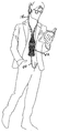
도 3은 착용된 본 발명의 피복부에 대한 제 2 실시예의 정면도;
도 4는 피복부의 제 3 실시예에 대한 정면도;
도 5는 본 발명의 제 4 실시예에 대한 정면도;
도 6은 본 발명의 피복부 또는 커버의 일 실시예에 대한 횡단면도;
도 7은 스크린이 커버의 일부로서 포함된 본 발명의 제 5 실시예에 대한 정면도.1 is a plan view of a prior art earphone set;
Figures 2a and 2b are front views of a first embodiment of a covering of the present invention for use with a portable music apparatus;
Figure 3 is a front view of a second embodiment of the covering portion of the present invention worn;
4 is a front view of a third embodiment of the covering portion;
5 is a front view of a fourth embodiment of the present invention;
6 is a cross-sectional view of one embodiment of a covering or cover of the present invention;
Figure 7 is a front view of a fifth embodiment of the present invention in which the screen is included as part of the cover;
이제 도면으로 돌아가서, 도 1은 휴대용 음악 장치와 함께 사용하기 위한 종래 기술의 휴대용 음악 장치(10) 및 케이블들(16, 18 및 20)의 평면도이다. Turning now to the drawings, FIG. 1 is a plan view of a prior art
본 발명이 휴대용 음악 장치들과 관련하여 설명하고 있는 반면, 독립적이고 유일한 미적 디자인 및 기능성을 가능하게 하는 가요성, 휴대용 전도체 커버에 대한 일반적인 교시가 본원에 개시된 근본적인 발명을 나타내고 있음을 알 수 있다.While the present invention has been described in connection with portable music devices, it can be seen that the general teachings of a flexible, portable conductor cover that enables independent and unique aesthetic design and functionality represent the fundamental invention disclosed herein.
도 1에 있어서, 종래 기술의 휴대용 음악 장치는 우측 이어폰(12) 및 좌측 이어폰(14)을 포함하며, 그 모두는 절연 와이어 또는 전도체(18)에 의해 분기 지점(16)에 연결된다. 상기 분기 지점(16)으로부터, 상기 2개의 와이어들(18)은 공통 와이어 또는 전도체(20) 내에 결합되며, 상기 전도체는 많은 제조자들의 휴대용 음악 장치들과 보편적으로 호환되는 디자인을 갖는 플러그(22)에 연결된다. 1, the prior art portable music apparatus includes a
도 1에 있어서, 와이어들(18, 20)은 상기 와이어들(18, 20)의 상대 길이가 변화할 수 있도록 제안하기 위한 파선 세그먼트들로 도시된다. 대표적으로, 와이어(20)는 기본적으로 분기 지점(16)으로 이어지는 와이어들(18)보다 길게 구성될 수 있다. 그러나, 그와 같은 경우가 필요치 않을 수 있으며, 케이블(20)과 같이, 본 발명의 일부 실시예들에 있어서는 완전히 짧을 수 있다.In Fig. 1, the
본 발명의 하나의 목적은 플러그(22)와 이어폰 사이에 케이블들(18, 20)에 대한 추가 벌크를 제공 및 보호하여, 상기 케이블들이 얽히고 상기 이어폰이 귀로부터 부주의하게 당겨지는 경향을 감소시키는 것이라는 사실을 상기한다.One object of the present invention is to provide and protect additional bulk for the
일반적으로, 이는 분기 지점과 전도체들을 차폐하는 커버와 함께 분기 지점(16)과 전도체(18)용 피복부 또는 커버를 제공하고, 또한 사용자가 부분적으로 착용하고 상기 전도체들이 걸려 뜯기는 것을 방지하기에 충분한 벌크 및 표면을 제공하며, 또한 그의 기능부를 차폐하는 매력적인 디자인을 제공하는 본 발명에 의해 수행된다. 음원과 이어폰 사이에 어떠한 와이어도 존재하지 않는 기술조차도 생각할 수 있다.In general, it provides a covering or cover for the
그와 같은 피복부 또는 커버를 생산 또는 제조하기 위한 한가지 방법은 대체로 평평한 조립체를 형성하는 절연층들 사이에 샌드위치되는 얇은 구리층으로 형성된 일반적으로 수동 전도체인 종래의 가요성 회로들을 사용하는 것이다. 가요성 회로들에 대하여는 Wikipedia.com에 설명되어 있다.One method for producing or fabricating such a covering or cover is to use conventional flexible circuits that are generally passive conductors formed of a thin copper layer sandwiched between insulating layers forming a generally flat assembly. Flexible circuits are described on Wikipedia.com.
본 발명은 도 1에 도시된 얇은 케이블들(16, 18)의 모두 또는 일부를 대체하는 이어폰들과 음원들 사이의 전기 신호들을 운반하는 전도체들을 반드시 포함하는 가요성 커버 또는 피복부를 제공한다. 본 발명의 가요성 커버 또는 피복부는 충분한 사이즈 또는 벌크로 제공되며 또한 사용자의 몸체에 안착시키거나 또는 착용되기에 충분히 얇게 되어, 상기 케이블이 몸체에 일치되며 또한, 일반적으로 얽히고 이탈하고 또한 다루기 힘들게 되는, 도 1에 도시된 일반적으로 느슨하게 매달려 다루기 힘든 케이블들을 최소화시킨다.The present invention provides a flexible cover or cover that necessarily includes conductors carrying electrical signals between earphones and sound sources replacing all or a portion of the
도 2a 및 도 2b에는 본 발명의 커버 또는 피복부(50)에 대한 정면 사시도가 도시되어 있다. 본 발명에 따른 본 실시예는 커버(50)와 함께 커버된 전도체들에 연결된 이어폰(12 및 14) 세트를 포함한다. 이어폰들(12 및 14)은 도 2a에서 대상자(52)의 각각의 귀 안에 배치된다. 휴대용 음악 장치(54)는 플러그(22) 및 와이어(20)의 단부에 연결되며, 도시된 바와 같이 편리하게도 포켓(55) 내에 배치될 수 있다. 상기 전도체(20)는 커버(50) 내에서 분기 지점(16)으로 계속되며, 전도체들(18)로 분열된다. 전도체(20)는 외부층들 사이에 샌드위치되는 캡슐화된 전도체나 또는 가요성 회로들과 관련하여 상술된 전도층의 일부로서 이어폰들(12, 14)과 연결된다.Figures 2a and 2b show a front perspective view of the cover or covering 50 of the present invention. This embodiment in accordance with the present invention includes a set of
도 3, 도 4 및 도 5는 본 발명의 가요성 전도체 피복부 또는 커버에 대한 대안적 실시예의 정면 사시도들을 나타낸다.Figures 3, 4 and 5 show front perspective views of an alternative embodiment of a flexible conductor overcoat or cover of the present invention.
도 3은 스카프와 같은 일반 의류의 외관을 갖는 가요성 커버(50)를 설명한다. 상기 가요성 커버의 외부층들은 도 3에 도시된 바와 같은 패턴 또는 스카프 형상(32)을 갖는 직물을 포함할 수 있으며, 그에 따라 실제로 상기 전도체를 차폐하고, 또한 착용자 몸체 상의 편리한 착용이 가능해진다. 이와 같은 커버(32)는 도 1에 따른 종래 기술의 케이블에 대한 느슨한 현수 방식을 실질적으로 제거한다. 이어폰들(12, 14)은 스카프(32)에 연결되나 실제로는 보이지 않는다.Figure 3 illustrates a
도 4는 상기 가요성 커버(50)가 코카콜라 병(42)과 같은 널리 공지된 심볼로 되도록 형성될 수 있는 본 발명에 따른 다른 실시예의 정면 사시도이다. 이와 같은 심볼(42)은 큰 벌크를 갖는 평평한 형상일 수 있으며 또한 다른 평평한 구조체가 착용자의 가슴에 대해 안착될 수 있으며, 따라서, 헤드폰으로부터의 전도체들의 분리를 최소화 한다. 상기 커버는 음원으로 연장하는 와이어(20)와 이어폰으로 연장하는 전도체들(18)을 갖는다4 is a front perspective view of another embodiment according to the present invention in which the
도 5는 음원과 헤드폰 사이의 전도체가 복수의 장식용 얇은 꼬리형 구조체들(44) 중 오직 하나에 안착되어, 상기 전도체를 추가로 차폐하고 또한 상기 전도체의 부주의한 얽힘과 걸림을 최소화 하는 본 발명의 또 다른 실시예이다.Figure 5 is a side view of the present invention in which the conductor between the sound source and the headphone is seated in only one of the plurality of decorative
도 6은 피복부 또는 커버(50)를 생성하기 위한 하나의 접근 방법에 대한 횡단면도이다. 커버(50)는, 실리콘 고무와 같은, 가요성, 유연성, 및 탄성 중합 수지 재료(52)로 몰딩된다. 커버(50)는 갭(62)을 통해 접근 가능한 통로(60)와 함께 몰딩된다. 와이어들(18, 20)이 상기 커버(50) 내에 배치될 때, 그들은 갭(62)을 통해 통로(60) 내로 압착된다. 이어서, 갭(62)은 열의 사용 또는 다른 수단을 통해 접착제로 밀봉될 수 있다. 대안적으로, 상기 갭(62)이 충분히 좁은 경우, 예를 들면 상기 갭(62)의 2개의 측면들이 서로 접촉할 때, 와이어들(18, 20)은 어떠한 밀봉 수단 없이도 기계적으로 통로(60) 내에 보유될 수 있다. 이와 같은 실시예는 상기 커버 또는 피복부(50)가 도 2a 내지 도 5에 도시된 것들을 포함하는 어떠한 소망의 장식용 외관으로 형성되도록 허용한다.FIG. 6 is a cross-sectional view of one approach to creating a covering or cover 50. FIG. The
가요성 회로 분야는 널리 공지되어 있으며, 또한 지속적으로 발전 중에 있으며, 또한 능동 소자 및 수동 소자 모두가 적합한 전기 회로를 제공하기 위해 통합될 수 있는 평평한 케이블 또는 평평한 밴드 외관을 갖는 평평한 회로를 포함한다.Background of the Invention The field of flexible circuits is well known and includes devices that are constantly evolving, as well as flat cables or flat circuits that have a flat band appearance that can be integrated to provide suitable electrical circuitry for both active and passive components.
본 발명은 상기 커버 또는 피복부의 표면 상에 스크린을 형성하기 위해 평평한 LCD를 포함할 수 있다. 물텍사(Multek)는 평평한 LCD 디스플레이의 소스이며, 후지쯔사(Fujitsu)는 평평한 가요성 LCD 스크린을 제공한다.The present invention may include a flat LCD to form a screen on the surface of the cover or cover. Multek is the source of flat LCD displays, and Fujitsu offers a flat, flexible LCD screen.
도 7은 커버 또는 피복부(50)가 스크린(70)을 포함하는 본 발명의 다른 실시예에 따른 정면도이다. 만약 휴대용 음악 장치가 비디오를 포함할 경우, 상기 스크린은 휴대용 음악 장치가 작동되는 동안 그와 같은 비디오를 보여줄 수 있다. 또한, 사용성, 다양성 및 응용성에 있어서 증가하는 개인용 휴대 장치로 인해, 사용자는, 도 7에 도시된 스크린(70)을 갖는 커버 또는 피복부(50) 내에 캡슐화된 능동 회로로, 그들이 좋아하는 DVD, 컴퓨터 저장 비디오, 또는 소망하는 어떠한 비디오를 볼 수 있다.7 is a front view in accordance with another embodiment of the present invention in which the cover or covering 50 includes a
또한, 평평한 LED는 영상 표시 또는 수동 제어되는 볼륨 조절로서 채용될 수 있다. 그와 같은 평평한 LED는 삼성사(Samsung)로부터 이용할 수 있으며, 가요성 OLED 스크린으로서 알려져있다. 소니사(Sony)도 또한 가요성 풀 칼라 페이퍼 스크린으로서 알려진 LED 스크린을 내놓고 있다. Also, flat LEDs can be employed as image display or manually controlled volume control. Such a flat LED is available from Samsung and is known as a flexible OLED screen. Sony is also releasing LED screens, also known as flexible full color paper screens.
RFID 디바이스가 본 발명의 커버(50) 내에 통합될 수 있으며, 그 경우 사용자의 고유 식별 코드가 용이하게 식별되지 않으면서 흔히 볼 수 있는 방식으로 이용 가능한 방법으로 수행될 수 있다. 상기 RFID 코드들은 음악 관련된 특정 정보나 또는 기타 관련된 정보로 제한될 수 있으나, 또한, 특히 도 3 내지 도 5에 도시된 바와 같이, 본 발명의 평평한 커버 또는 피복부가 히든 방식(hidden manner)의 다용도를 제공하게 하기 위한, 은행 코드와 같은 개인 식별 정보를 포함할 수도 있다.The RFID device may be integrated into the
또한, 노키아(Nokia) N97과 같은, 카메라를 구비한 미니 휴대폰은 커버(50)에 합체될 수 있다. In addition, a mini-phone with a camera, such as Nokia N97, can be incorporated into the
본 발명에 따른 커버(50)는 사람의 신체 상에 지지 또는 안착되도록 의도되며, 또한 음원과 이어폰 사이에 위치될 수 있다. 다른 한편으로, 본 발명에 따른 가요성 회로(커버)는 또한 손목으로서 형성될 수 있으며 또한 식별된 능동 소자 및/또는 RFID 칩들 위로 운반될 수 있다.The
얇고 평평하고 가요성을 갖는 리튬 배터리들이 증가하고 있으며, 그와 같은 배터리들은 커버 내에 통합되는 능동 소자들에 적합한 전력을 제공하기 위해 본 발명의 커버 내에 통합될 수 있다. 그와 같은 가요성 배터리는 소리케어사(Solicare Inc.)로부터 이용할 수 있으며 또한 플렉시온(Flexion) 상표로 판매되는 초박형 가요성 리튬 배터리를 포함한다.Flat, flexible lithium batteries are increasing, and such batteries may be integrated within the cover of the present invention to provide power suitable for active components incorporated into the cover. Such flexible batteries include ultra-thin flexible lithium batteries available from Solicare Inc. and also sold under the Flexion trademark.
하나의 일반적인 회로 구조체는 2개의 PET층들 사이에 얇은 구리 스트립들을 적층한 가요성 포일이다. 본 발명의 교시에 따르면, 얇은 외부층들은 상기 PET층들에 부착될 수 있으며, 그와 같은 외부층들은 전자 케이블보다는 의복류의 외관을 제공하는 직물 또는 적합한 디자인을 포함할 수 있다. 그와 같은 재료의 예로서는 샤무트사(Shawmut Corp)에 의해 제공되는 것을 들 수 있으며, 본 발명의 커버(50)를 형성하는 종래 가요성 회로에 부착되기에 적합한 헤드라이너 직물(headliner fabric)을 들 수 있다. One common circuit structure is a flexible foil in which thin copper strips are laminated between two PET layers. According to the teachings of the present invention, thin outer layers may be attached to the PET layers, and such outer layers may include a fabric or a suitable design that provides an appearance of the garment rather than an electronic cable. Examples of such materials include those provided by Shawmut Corp and include a headliner fabric suitable for attachment to conventional flexible circuits forming the
상술된 바와 같이, 본 발명은 또한, 폴리이미드, PEEK, 또는 투명 전도성 폴리에스터와 같은, 가요성 플라스틱 기판 상에 회로를 장착함으로써 전자 회로를 조립하기 위한 기술인, 플렉스 회로로 알려진 가요성 전자 장치를 사용한다. 플렉스 회로는 또한 폴리에스터 상에 스크린 인쇄된 실버 회로일 수 있다. 본 발명은 주로 2개의 PET층들 사이에 매우 얇은 구리 스트립들을 적층시킴으로써 케이블을 형성하기 위해 가요성 포일 회로들을 사용한다. 대표적으로 0.05 mm 두께를 갖는 이들 PET층들은 열경화성인 접착제로 코팅되며 적층 공정 동안 활성화된다.As described above, the present invention also provides a flexible electronic device known as a flex circuit, which is a technique for assembling an electronic circuit by mounting a circuit on a flexible plastic substrate, such as polyimide, PEEK, or transparent conductive polyester use. The flex circuit may also be a silver circuit screen printed on polyester. The present invention primarily uses flexible foil circuits to form cables by stacking very thin copper strips between two PET layers. These PET layers, which typically have a thickness of 0.05 mm, are coated with a thermosetting adhesive and are activated during the lamination process.
본 발명은 착용자의 신체 상에 실제로 안착되는 가요성 커버 또는 플렉스 회로를 갖는 이어폰에 음원을 연결하기 위한 전도체를 제공함으로써 플렉스 회로의 사이즈, 벌크 및 두께에 있어서 장점을 갖는다. 이는 도 1에 도시된 바와 같은 느슨하게 매달린 와이어들의 킹킹(kinking), 비틀림 또는 기타 바람직하지 않은 양태들을 현저히 제거한다.The present invention has advantages in size, bulk, and thickness of the flex circuit by providing a conductor for connecting a sound source to an earphone having a flexible cover or flex circuit that is actually seated on the wearer's body. This significantly removes the kinking, twisting or other undesirable aspects of the loosely suspended wires as shown in Fig.
본 발명은 휴대용 음악 플레이어의 실시예로 도시되었으나, 그와 같은 전도체들의 유익한 용례들은 또한 다른 환경에서도 채용될 수 있다. 이들은 USB 케이블, 기타 및 키보드 케이블, 마이크로폰 및 스피커 케이블, RCA 커넥터 케이블, 파워 라인, 데스크 세트 텔레폰 및 램프 등을 포함할 수 있다. While the invention has been shown as an embodiment of a portable music player, beneficial applications of such conductors may also be employed in other environments. These may include USB cables, guitar and keyboard cables, microphone and speaker cables, RCA connector cables, power lines, desk set telephones, and lamps.
요약하면, 본 발명은 개별적인 심미적 디자인 및 외관이 가능한 전도체용 가요성, 휴대용 커버 또는 피복부를 지향하며, 상기 전도체는 한 단부에서 전력, 비디오, 오디오 등과 같은 신호 소스에 연결되며, 그와 같은 신호를 수신하기 위해 상기 디바이스에 접속되고, 본 발명의 휴대용 가요성 전도체 커버가 전도체를 차폐하도록 작용할 수 있는 이어폰, 데스크 램프, 어쿠스틱 기타 또는 어떠한 기타 환경이 그와 같은 전도체가 얽히거나 또한 다루기 힘들게 되는 것으로부터 방지하고, 또한 독립적으로 그와 같은 커버 또는 피복부의 기능부를 추가로 차폐하여 미려한 외관을 제공한다. Briefly, the present invention is directed to a flexible, portable cover or sheath for a conductor that can be individually aesthetically designed and appearance, said conductor being connected at one end to a signal source such as power, video, audio, Earphones, desk lamps, acoustic guitars, or any other environment that may be operable to shield the conductors of the portable flexible conductor cover of the present invention, which are connected to the device for receiving, such that such conductors may become entangled or unmanageable And additionally shields the function of such cover or cover independently to provide an elegant appearance.
적합한 실시예는 본 발명의 원리들에 대한 최상의 설명을 제공하도록 기술되었으며, 따라서 당업자라면 본 발명의 다양한 실시예들에 있어서 다양한 변형 형태를 사용하여 고려된 특정 용도에 적합한 실제 응용을 제공받을 수 있다는 사실을 이해해야 할 것이다. 그와 같은 모든 변형 및 변경은, 매우 합법적이고 공정한 권리 범위에 따라 이해하는 한, 첨부된 청구항들에 의해 결정되는 본 발명의 범위 내에 있게 된다.The preferred embodiments have been described so as to provide a best illustration of the principles of the invention and, therefore, those skilled in the art will readily appreciate that various embodiments of the invention may be used to provide practical applications suitable for the particular use contemplated You will have to understand the fact. All such modifications and variations are within the scope of the invention as determined by the appended claims, so long as they are understood in accordance with a very legal and fair scope of rights.
Claims (17)
절연층들 사이에 샌드위치(sandwiched)되는 상기 전도체를 포함하는 휴대용 가요성 커버를 포함하며,
상기 가요성 커버는 그 안에 안착되는 상기 전도체보다 대체로 큰 사이즈 및 벌크(bulk)를 가지며, 또한 상기 가요성 커버를 표면 상에 안착시키고 또한 필요한 경우 즉시 제거할 수 있는 가요성 및 벌크를 가지며,
상기 가요성 커버는 실제로 그의 기능부를 차폐(masking)하기에 적합한 미려한 외관으로 형성되는 전기 전도체용 커버.A cover for an electrical conductor, the conductor being positioned between a signal source and a device to be actuated by the signals, and configured to carry acoustic between speakers that are seated within the user's ear and a sound source that is placed separately. In the cover,
A portable flexible cover comprising said conductor sandwiched between insulating layers,
The flexible cover having a substantially larger size and bulk than the conductor resting thereon and also having a flexible and bulk that seats the flexible cover on the surface and can be removed immediately if necessary,
Wherein the flexible cover is formed with a beautiful appearance suitable for actually masking its function.
상기 가요성 커버는 그 안에 안착되는 상기 전도체보다 대체로 큰 사이즈 및 벌크를 가지며, 또한 상기 가요성 커버를 표면 상에 안착시키고 또한 필요한 경우 즉시 제거할 수 있는 가요성 및 벌크를 가지며,
상기 가요성 커버는 실제로 그의 기능부를 차폐하기에 적합한 장식용 외관으로 형성되는 전기 전도체용 커버.2. The device of claim 1, wherein the device comprises portable speakers such as headphones, the source is a sound source,
Wherein the flexible cover has a substantially larger size and bulk than the conductor that is seated therein and also has a flexible and bulk capable of seating the flexible cover on a surface and removing it immediately if necessary,
Wherein the flexible cover is actually formed as a decorative outer tube suitable for shielding its function.
Applications Claiming Priority (5)
| Application Number | Priority Date | Filing Date | Title |
|---|---|---|---|
| US201161486983P | 2011-05-17 | 2011-05-17 | |
| US61/486,983 | 2011-05-17 | ||
| US13/473,039 US20120314895A1 (en) | 2011-05-17 | 2012-05-16 | Sheath to mask electrical conductor |
| US13/473,039 | 2012-05-16 | ||
| PCT/US2012/038241 WO2012158862A1 (en) | 2011-05-17 | 2012-05-17 | Sheath to mask electrical conductor |
Publications (1)
| Publication Number | Publication Date |
|---|---|
| KR20140068806A true KR20140068806A (en) | 2014-06-09 |
Family
ID=47177332
Family Applications (1)
| Application Number | Title | Priority Date | Filing Date |
|---|---|---|---|
| KR1020137033520A Withdrawn KR20140068806A (en) | 2011-05-17 | 2012-05-17 | Sheath to mask electrical conductor |
Country Status (7)
| Country | Link |
|---|---|
| US (1) | US20120314895A1 (en) |
| EP (1) | EP2710814A4 (en) |
| KR (1) | KR20140068806A (en) |
| CN (1) | CN104081790A (en) |
| AU (1) | AU2012255778A1 (en) |
| CA (1) | CA2873848A1 (en) |
| WO (1) | WO2012158862A1 (en) |
Families Citing this family (2)
| Publication number | Priority date | Publication date | Assignee | Title |
|---|---|---|---|---|
| CN103653430A (en) * | 2013-12-03 | 2014-03-26 | 苏州爱马仕服饰有限公司 | Method for manufacturing scarf with earphones |
| US9420366B2 (en) | 2015-01-14 | 2016-08-16 | Heidi Lynne Whitney | Earbud accessory |
Family Cites Families (18)
| Publication number | Priority date | Publication date | Assignee | Title |
|---|---|---|---|---|
| US5438698A (en) * | 1992-12-14 | 1995-08-01 | Sweat Accessories, Inc. | Wearable audio reception device |
| DE69930134T2 (en) * | 1998-09-17 | 2006-12-21 | Koninklijke Philips Electronics N.V. | METHOD FOR PRODUCING A SEMICONDUCTOR BODY AT THE SURFACE OF WHICH IS A COIL WITH A MAGNETIC CORE |
| US20060076048A1 (en) * | 2000-04-27 | 2006-04-13 | Russell Gaudiana | Photo-sensing photovoltaic with positioning facility |
| GB0014321D0 (en) * | 2000-06-12 | 2000-08-02 | Koninkl Philips Electronics Nv | Garment with removable electronic devices |
| US6798391B2 (en) * | 2001-01-02 | 2004-09-28 | Xybernaut Corporation | Wearable computer system |
| KR200235821Y1 (en) * | 2001-03-02 | 2001-09-28 | 박성환 | Fixable-wire earphone |
| JP2004180252A (en) * | 2002-11-28 | 2004-06-24 | Toshiaki Ichige | Decoration fitting for earphone code and earphone code |
| JP4091832B2 (en) * | 2002-12-13 | 2008-05-28 | アルプス電気株式会社 | Input device |
| US7436318B2 (en) * | 2004-04-19 | 2008-10-14 | Atg Designworks, Llc | Self contained device for displaying electronic information |
| US7399198B2 (en) * | 2004-09-13 | 2008-07-15 | Sharper Image Corp. | Device with speaker and retractable cable unit |
| US20070076907A1 (en) * | 2005-09-20 | 2007-04-05 | Stagni Mary K | Sound meter for portable audio headphones |
| US8269111B2 (en) * | 2006-10-25 | 2012-09-18 | George Scifo | Scrunch-it earpiece/wire organizer and method of using same |
| WO2008152539A1 (en) * | 2007-06-11 | 2008-12-18 | Nxp B.V. | A cable management device, and a method of managing cables of an audio playback apparatus |
| US8311260B2 (en) * | 2008-03-19 | 2012-11-13 | Seaborn Ii, Llc | Miniature stereo audio earphones |
| US9154866B2 (en) * | 2009-06-10 | 2015-10-06 | Apple Inc. | Fiber-based electronic device structures |
| US8687834B2 (en) * | 2009-06-25 | 2014-04-01 | Jerry Leigh Of California, Inc. | Garment with built-in audio source wiring |
| US8107653B2 (en) * | 2009-06-25 | 2012-01-31 | Jerry Leigh Of California, Inc. | Garment with built-in audio source wiring |
| KR200450124Y1 (en) * | 2009-10-22 | 2010-09-07 | 이수경 | Tubular earphone |
-
2012
- 2012-05-16 US US13/473,039 patent/US20120314895A1/en not_active Abandoned
- 2012-05-17 AU AU2012255778A patent/AU2012255778A1/en not_active Abandoned
- 2012-05-17 CA CA2873848A patent/CA2873848A1/en not_active Abandoned
- 2012-05-17 WO PCT/US2012/038241 patent/WO2012158862A1/en not_active Ceased
- 2012-05-17 CN CN201280035754.XA patent/CN104081790A/en active Pending
- 2012-05-17 EP EP12785705.0A patent/EP2710814A4/en not_active Withdrawn
- 2012-05-17 KR KR1020137033520A patent/KR20140068806A/en not_active Withdrawn
Also Published As
| Publication number | Publication date |
|---|---|
| CA2873848A1 (en) | 2012-11-22 |
| EP2710814A4 (en) | 2015-05-06 |
| EP2710814A1 (en) | 2014-03-26 |
| CN104081790A (en) | 2014-10-01 |
| WO2012158862A1 (en) | 2012-11-22 |
| AU2012255778A1 (en) | 2014-01-16 |
| US20120314895A1 (en) | 2012-12-13 |
Similar Documents
| Publication | Publication Date | Title |
|---|---|---|
| CN201726512U (en) | Wired earphones | |
| US11653128B2 (en) | Fabric-covered electronic device | |
| CN106484040B (en) | Enclosing characteristic portion for accessory device | |
| TW201127093A (en) | Insert earphone with capacitance-sensing function | |
| US20190052965A1 (en) | Electronic Devices with Motion-Based Orientation Sensing | |
| TWD117942S1 (en) | A dongle with wearable stereo headset | |
| CN105981403A (en) | Wearable Electronic System | |
| WO2001078354A2 (en) | Hands-free communication device | |
| KR20170136293A (en) | Portable sound equipment | |
| KR20140068806A (en) | Sheath to mask electrical conductor | |
| US20200083736A1 (en) | Portable electronic device | |
| CN107925803B (en) | Sound transmission device and sound transmission system | |
| KR101553610B1 (en) | Wearable device having snap connector | |
| CN220191007U (en) | Display module and Bluetooth sport sound box using same | |
| CN206506674U (en) | Earmuff set with touch function and its headset | |
| TWI405473B (en) | Wired headset with integrated switch | |
| KR20190056215A (en) | Gaming Microphone Earphones | |
| CN205406794U (en) | Earphone plug | |
| CN2619430Y (en) | Structure to reduce electromagnetic waves of mobile phone speakers | |
| AU2011232790B2 (en) | Wired headset with integrated switch | |
| HK1136438A (en) | Wired headset with integrated switch | |
| HK1136438B (en) | Wired headset with integrated switch | |
| TWM494444U (en) | Wrist type resonance sounding device |
Legal Events
| Date | Code | Title | Description |
|---|---|---|---|
| PA0105 | International application |
Patent event date: 20131217 Patent event code: PA01051R01D Comment text: International Patent Application |
|
| PG1501 | Laying open of application | ||
| PC1203 | Withdrawal of no request for examination | ||
| WITN | Application deemed withdrawn, e.g. because no request for examination was filed or no examination fee was paid |