KR20130010878A - Braze foil for high-temperature brazing and methods for repairing or producing components using said braze foil - Google Patents
Braze foil for high-temperature brazing and methods for repairing or producing components using said braze foil Download PDFInfo
- Publication number
- KR20130010878A KR20130010878A KR1020120079002A KR20120079002A KR20130010878A KR 20130010878 A KR20130010878 A KR 20130010878A KR 1020120079002 A KR1020120079002 A KR 1020120079002A KR 20120079002 A KR20120079002 A KR 20120079002A KR 20130010878 A KR20130010878 A KR 20130010878A
- Authority
- KR
- South Korea
- Prior art keywords
- braze
- foil
- brazing
- braze foil
- powder
- Prior art date
- Legal status (The legal status is an assumption and is not a legal conclusion. Google has not performed a legal analysis and makes no representation as to the accuracy of the status listed.)
- Granted
Links
Images


Classifications
-
- B—PERFORMING OPERATIONS; TRANSPORTING
- B23—MACHINE TOOLS; METAL-WORKING NOT OTHERWISE PROVIDED FOR
- B23K—SOLDERING OR UNSOLDERING; WELDING; CLADDING OR PLATING BY SOLDERING OR WELDING; CUTTING BY APPLYING HEAT LOCALLY, e.g. FLAME CUTTING; WORKING BY LASER BEAM
- B23K35/00—Rods, electrodes, materials, or media, for use in soldering, welding, or cutting
- B23K35/22—Rods, electrodes, materials, or media, for use in soldering, welding, or cutting characterised by the composition or nature of the material
- B23K35/24—Selection of soldering or welding materials proper
-
- B—PERFORMING OPERATIONS; TRANSPORTING
- B23—MACHINE TOOLS; METAL-WORKING NOT OTHERWISE PROVIDED FOR
- B23K—SOLDERING OR UNSOLDERING; WELDING; CLADDING OR PLATING BY SOLDERING OR WELDING; CUTTING BY APPLYING HEAT LOCALLY, e.g. FLAME CUTTING; WORKING BY LASER BEAM
- B23K1/00—Soldering, e.g. brazing, or unsoldering
- B23K1/0008—Soldering, e.g. brazing, or unsoldering specially adapted for particular articles or work
- B23K1/0018—Brazing of turbine parts
-
- B—PERFORMING OPERATIONS; TRANSPORTING
- B23—MACHINE TOOLS; METAL-WORKING NOT OTHERWISE PROVIDED FOR
- B23K—SOLDERING OR UNSOLDERING; WELDING; CLADDING OR PLATING BY SOLDERING OR WELDING; CUTTING BY APPLYING HEAT LOCALLY, e.g. FLAME CUTTING; WORKING BY LASER BEAM
- B23K35/00—Rods, electrodes, materials, or media, for use in soldering, welding, or cutting
- B23K35/02—Rods, electrodes, materials, or media, for use in soldering, welding, or cutting characterised by mechanical features, e.g. shape
- B23K35/0222—Rods, electrodes, materials, or media, for use in soldering, welding, or cutting characterised by mechanical features, e.g. shape for use in soldering or brazing
- B23K35/0233—Sheets or foils
- B23K35/0238—Sheets or foils layered
-
- B—PERFORMING OPERATIONS; TRANSPORTING
- B23—MACHINE TOOLS; METAL-WORKING NOT OTHERWISE PROVIDED FOR
- B23K—SOLDERING OR UNSOLDERING; WELDING; CLADDING OR PLATING BY SOLDERING OR WELDING; CUTTING BY APPLYING HEAT LOCALLY, e.g. FLAME CUTTING; WORKING BY LASER BEAM
- B23K35/00—Rods, electrodes, materials, or media, for use in soldering, welding, or cutting
- B23K35/02—Rods, electrodes, materials, or media, for use in soldering, welding, or cutting characterised by mechanical features, e.g. shape
- B23K35/0222—Rods, electrodes, materials, or media, for use in soldering, welding, or cutting characterised by mechanical features, e.g. shape for use in soldering or brazing
- B23K35/0244—Powders, particles or spheres; Preforms made therefrom
-
- B—PERFORMING OPERATIONS; TRANSPORTING
- B23—MACHINE TOOLS; METAL-WORKING NOT OTHERWISE PROVIDED FOR
- B23K—SOLDERING OR UNSOLDERING; WELDING; CLADDING OR PLATING BY SOLDERING OR WELDING; CUTTING BY APPLYING HEAT LOCALLY, e.g. FLAME CUTTING; WORKING BY LASER BEAM
- B23K35/00—Rods, electrodes, materials, or media, for use in soldering, welding, or cutting
- B23K35/22—Rods, electrodes, materials, or media, for use in soldering, welding, or cutting characterised by the composition or nature of the material
- B23K35/24—Selection of soldering or welding materials proper
- B23K35/30—Selection of soldering or welding materials proper with the principal constituent melting at less than 1550°C
- B23K35/3033—Ni as the principal constituent
-
- B—PERFORMING OPERATIONS; TRANSPORTING
- B23—MACHINE TOOLS; METAL-WORKING NOT OTHERWISE PROVIDED FOR
- B23K—SOLDERING OR UNSOLDERING; WELDING; CLADDING OR PLATING BY SOLDERING OR WELDING; CUTTING BY APPLYING HEAT LOCALLY, e.g. FLAME CUTTING; WORKING BY LASER BEAM
- B23K35/00—Rods, electrodes, materials, or media, for use in soldering, welding, or cutting
- B23K35/22—Rods, electrodes, materials, or media, for use in soldering, welding, or cutting characterised by the composition or nature of the material
- B23K35/24—Selection of soldering or welding materials proper
- B23K35/30—Selection of soldering or welding materials proper with the principal constituent melting at less than 1550°C
- B23K35/3046—Co as the principal constituent
-
- F—MECHANICAL ENGINEERING; LIGHTING; HEATING; WEAPONS; BLASTING
- F01—MACHINES OR ENGINES IN GENERAL; ENGINE PLANTS IN GENERAL; STEAM ENGINES
- F01D—NON-POSITIVE DISPLACEMENT MACHINES OR ENGINES, e.g. STEAM TURBINES
- F01D25/00—Component parts, details, or accessories, not provided for in, or of interest apart from, other groups
- F01D25/28—Supporting or mounting arrangements, e.g. for turbine casing
-
- F—MECHANICAL ENGINEERING; LIGHTING; HEATING; WEAPONS; BLASTING
- F02—COMBUSTION ENGINES; HOT-GAS OR COMBUSTION-PRODUCT ENGINE PLANTS
- F02C—GAS-TURBINE PLANTS; AIR INTAKES FOR JET-PROPULSION PLANTS; CONTROLLING FUEL SUPPLY IN AIR-BREATHING JET-PROPULSION PLANTS
- F02C7/00—Features, components parts, details or accessories, not provided for in, or of interest apart form groups F02C1/00 - F02C6/00; Air intakes for jet-propulsion plants
-
- B—PERFORMING OPERATIONS; TRANSPORTING
- B23—MACHINE TOOLS; METAL-WORKING NOT OTHERWISE PROVIDED FOR
- B23K—SOLDERING OR UNSOLDERING; WELDING; CLADDING OR PLATING BY SOLDERING OR WELDING; CUTTING BY APPLYING HEAT LOCALLY, e.g. FLAME CUTTING; WORKING BY LASER BEAM
- B23K2101/00—Articles made by soldering, welding or cutting
- B23K2101/001—Turbines
-
- F—MECHANICAL ENGINEERING; LIGHTING; HEATING; WEAPONS; BLASTING
- F05—INDEXING SCHEMES RELATING TO ENGINES OR PUMPS IN VARIOUS SUBCLASSES OF CLASSES F01-F04
- F05D—INDEXING SCHEME FOR ASPECTS RELATING TO NON-POSITIVE-DISPLACEMENT MACHINES OR ENGINES, GAS-TURBINES OR JET-PROPULSION PLANTS
- F05D2230/00—Manufacture
- F05D2230/20—Manufacture essentially without removing material
- F05D2230/23—Manufacture essentially without removing material by permanently joining parts together
- F05D2230/232—Manufacture essentially without removing material by permanently joining parts together by welding
- F05D2230/237—Brazing
-
- Y—GENERAL TAGGING OF NEW TECHNOLOGICAL DEVELOPMENTS; GENERAL TAGGING OF CROSS-SECTIONAL TECHNOLOGIES SPANNING OVER SEVERAL SECTIONS OF THE IPC; TECHNICAL SUBJECTS COVERED BY FORMER USPC CROSS-REFERENCE ART COLLECTIONS [XRACs] AND DIGESTS
- Y10—TECHNICAL SUBJECTS COVERED BY FORMER USPC
- Y10T—TECHNICAL SUBJECTS COVERED BY FORMER US CLASSIFICATION
- Y10T29/00—Metal working
- Y10T29/49—Method of mechanical manufacture
- Y10T29/49316—Impeller making
- Y10T29/49318—Repairing or disassembling
Landscapes
- Engineering & Computer Science (AREA)
- Mechanical Engineering (AREA)
- General Engineering & Computer Science (AREA)
- Chemical & Material Sciences (AREA)
- Combustion & Propulsion (AREA)
- Turbine Rotor Nozzle Sealing (AREA)
- Other Surface Treatments For Metallic Materials (AREA)
- Laminated Bodies (AREA)
- Arc Welding In General (AREA)
- Pressure Welding/Diffusion-Bonding (AREA)
Abstract
본 발명은 고온 브레이징용 코팅된 Ni 계, Co 계 또는 Ni-Co 계 브레이즈 호일 (1) 및 또한 발명에 따른 브레이즈 호일을 이용해 부품, 특히 가스 터빈 블레이드 또는 베인을 제조 또는 보수하기 위해 단결정 또는 일방향 응고된 초합금으로 만들어진 적어도 2 개의 부품 요소를 연결하는 방법에 관한 것이다. 용융 스핀 프로세스에 의하여 제조된 비정질 브레이즈 호일 (1) 은 상측과 하측을 가지고, 상측과 하측이 나노미터 범위의 입자 크기를 가지는 금속성 Ni 계, Co 계 또는 Ni-Co 계 브레이즈 분말 (2) 의 필름으로 얇게 코팅되고, 브레이즈 호일 (1) 과 또한 브레이즈 분말 (2) 양자는 합금 원소로서 결정립계 안정화 원소를 더 포함한다. 게다가, 용융점 강하제는 상업적으로 통상의 양으로 또는 상당히 증가된 비율로 브레이즈 호일 또는 나노 브레이즈 분말 (2) 에 존재할 수 있다. 본 발명에 따라 코팅된 브레이즈 호일 (1) 로, 인접한 모재 (10) 에서 브레이징할 때, 브레이즈 재료의 용융 온도 및 또한 재결정화의 확률 양자가 유리하게도 감소된다.The invention relates to single crystal or unidirectional solidification for the production or repair of parts, in particular gas turbine blades or vanes, using coated Ni-, Co- or Ni-Co-based braze foils (1) for high temperature brazing and also the braze foils according to the invention. The method relates to connecting at least two component elements made of superalloy. The amorphous braze foil 1 produced by the melt spin process has a film of metallic Ni-based, Co-based or Ni-Co-based braze powder 2 having an upper side and a lower side, and having an upper side and a lower side having a particle size in the nanometer range. Coated thinly, both the braze foil 1 and also the braze powder 2 further contain grain boundary stabilizing elements as alloy elements. In addition, the melting point depressant may be present in the braze foil or nano braze powder 2 in a commercially conventional amount or in a significantly increased proportion. With braze foil 1 coated according to the invention, when brazing in the adjacent base material 10, both the melting temperature of the braze material and also the probability of recrystallization is advantageously reduced.
Description
본 발명은 재료 과학 분야에 관련된다. 이것은 용융 스핀 프로세스에 의하여 제조된 고온 브레이징용의 비정질 브레이즈 호일 및, 본 발명에 따른 브레이즈 호일을 이용해 부품, 특히 가스 터빈 블레이드 또는 베인을 제조 또는 보수하기 위해 단결정 또는 일방향 응고된 (directionally solidified) 초합금으로 만들어진 적어도 2 개의 부품 요소를 연결하는 방법에 관한 것이다.The present invention relates to the field of materials science. It is an amorphous braze foil for hot brazing produced by a melt spin process and a single crystal or directionally solidified superalloy for the manufacture or repair of parts, in particular gas turbine blades or vanes, using the braze foil according to the invention. A method of connecting at least two component elements made.
매우 높은 부하 온도에서, 초합금, 예를 들어 니켈계, 코발트계 또는 니켈-코발트계 초합금으로 만들어진 단결정 또는 일방향 응고된 부품은, 무엇보다도, 우수한 재료 강도뿐만 아니라 우수한 내식성과 우수한 내산화성뿐만 아니라 우수한 크리프 강도를 가진다. 이 특성들의 조합으로 인해, 터빈의 흡기 온도는 예컨대 가스 터빈에서 이러한 그렇지만 매우 비싼 재료를 사용할 때 크게 증가될 수 있어서, 플랜트의 효율이 증가한다. 따라서, 1400 ℃ 를 초과하는 고온 가스 범위에서 작동 온도는, 가스 터빈의 다수의 부품, 예컨대 가이드 베인과 회전자 블레이드 또는 연소 챔버 라이너가 노출되는 부하 온도이다. 이런 높은 열 응력 이외에, 터빈 회전자 블레이드는 특히 또한 예를 들어 높은 기계적 부하를 받는다. 터빈의 작동 중, 이것은 전체적으로 재료에 바람직하지 못한 균열부를 발생시킬 수 있어서, 이런 식으로 손상된 부품은 새로운 부품으로 교체되거나 그렇지 않으면 보수되어야 한다.At very high load temperatures, monocrystalline or unidirectional solidified parts made of superalloys such as nickel-based, cobalt-based or nickel-cobalt-based superalloys, among other things, have excellent creep as well as good material strength as well as good corrosion resistance and good oxidation resistance. Has strength. Due to the combination of these characteristics, the intake temperature of the turbine can be greatly increased when using such but very expensive materials, for example in gas turbines, thereby increasing the efficiency of the plant. Thus, in the hot gas range above 1400 ° C., the operating temperature is the load temperature at which many parts of the gas turbine are exposed, such as guide vanes and rotor blades or combustion chamber liners. In addition to these high thermal stresses, turbine rotor blades are also particularly subjected to high mechanical loads, for example. During operation of the turbine, this can cause undesirable cracks in the material as a whole, so that parts damaged in this way have to be replaced or otherwise repaired with new parts.
위에서 이미 언급한 것처럼, 하지만, 단결정 또는 일방향 응고된 새로운 터빈 부품의 제조는 매우 많은 비용이 들고, 큰 부품인 경우에 충분한 재료 품질 (연속 단결정 또는 일방향 응고된 조직) 면에서 복잡하므로, 보통 존재하는 손상된 부품을 보수하려고 시도되고, 즉 부품의 기능이 보수에 의해 회복되어야 하고 그 후 보수된 부품은 터빈에서 추가 유지보수 기간 동안 다시 사용되어야 한다.As already mentioned above, however, the production of new single-crystal or unidirectional solidified turbine components is very expensive, and is usually present in large parts because of their complex material quality (continuous single crystal or unidirectional solidified tissue). Attempts are made to repair damaged parts, ie the function of the parts must be restored by repair and then the repaired parts must be used again during further maintenance periods in the turbine.
하지만, 종래의 다결정 미세조직을 가지는 손상된 부품의 보수와 비교했을 때, 단결정 또는 일방향 응고된 부품의 보수된 구역은 또한 대응하는 단결정 또는 일방향 응고된 미세조직을 가져야 하기 때문에, 손상된 단결정 또는 일방향 응고된 가스 터빈 부품의 보수가 상당히 더욱 어렵고; 그렇지 않으면, 보수된 구역에서 특성들이 바람직하지 못하게 악화된다.However, compared to the repair of damaged parts with conventional polycrystalline microstructures, the repaired zones of monocrystalline or unidirectional solidified parts must also have corresponding monocrystalline or unidirectional solidified microstructures, so that damaged monocrystalline or unidirectional solidified Repair of gas turbine components is considerably more difficult; Otherwise, the properties deteriorate undesirably in the repaired area.
예를 들어, 브레이징 프로세스를 사용함으로써 손상된 가스 터빈 부품을 보수하는 종래 기술 (예컨대, EP 1 258 545 B1 참조) 이 공지되어 있다. 이 경우에, 브레이즈 합금이 부품의 재료 손상 구역에서, 예컨대 균열부 구역에서 모재 (base material) 에 적용되고, 균열부로 도입된 후, 열 작용 (처리 온도는 브레이즈 합금의 용융 온도를 초과해야 하지만 모재의 용융 온도 미만이어야 함) 에 의해 용융되고 모재에 일체로 본딩된다. EP 1 258 545 B1 인 경우에, 1 ~ 3 중량% B 의 용융점 강하제가 보통 브레이즈 합금의 용융 온도를 감소시키기 위해서 브레이즈 합금에 첨가된다.For example, prior art for repairing damaged gas turbine parts by using a brazing process is known (see eg
또한, 공지되어 있지만 여기에서 더 자세히 설명되지 않는 손상된 가스 터빈 부품을 보수하기 위한 용접 프로세스와 비교했을 때, 브레이징 프로세스는 모재가 브레이징하는 동안 용융되지 않아서 모재의 단결정 조직이 원래대로 유지될 수 있는 장점을 가진다.In addition, compared to the welding process for repairing damaged gas turbine parts that are known but not described in more detail here, the brazing process has the advantage that the single crystal structure of the base material can be kept intact as the base material does not melt during brazing. Has
브레이징의 경우 열 처리하는 동안 재료에서 확산 프로세스가 발생하고, 이것은, 무엇보다도, 붕소와 같은 용융점 강하제가 브레이즈 합금으로부터 둘러싸는 모재로 확산되는 효과를 가진다. 브레이즈 합금은 붕소 농도의 감소 결과 응고되는 반면, 모재는 브레이즈 합금을 둘러싸는 구역에서 증가된 붕소 농도를 가지는데, 이것은 불리하게도 취성 붕소화물의 석출을 이끌 수 있다.In the case of brazing, a diffusion process takes place in the material during the heat treatment, which, among other things, has the effect that the melting point depressant, such as boron, diffuses into the surrounding substrate from the braze alloy. The braze alloy solidifies as a result of a decrease in boron concentration, while the base material has an increased boron concentration in the zone surrounding the braze alloy, which can adversely lead to precipitation of brittle borides.
게다가, 모재와 달리, 브레이즈 재료는 주요한 열 작용 때문에 많은 경우에 브레이징 이후 단결정 또는 일방향 응고된 조직을 가질 수 없다는 점에서 또한 불리하다. 이것은 무엇보다도 가스 터빈 부품에 사용되는 내고온성 초합금이 또한 매우 높은 온도에서 브레이징되어야 한다는 사실에 기인한 것일 수 있다. 보수될 구역, 예를 들어 균열부 내부의 잔류 응력 레벨에 따라, 그러면 균열부 표면을 따라 재결정화 확률이 매우 높다. 이것은 특히 브레이징 사이클 전, 준비 프로세스 동안 기계 가공, 예를 들어 그라인딩 (grinding), 샌드블래스팅 (sandblasting) 또는 숏 피닝 (shot peening) 을 받는 표면에 적용된다.In addition, unlike the base material, the braze material is also disadvantageous in that it cannot in many cases have a single crystal or unidirectional solidified structure after brazing because of the major thermal action. This may be due, among other things, to the fact that the high temperature resistant superalloys used in gas turbine components must also be brazed at very high temperatures. Depending on the residual stress level inside the area to be repaired, for example the crack, then the probability of recrystallization along the crack surface is very high. This applies in particular to surfaces subjected to machining, for example grinding, sandblasting or shot peening, before the brazing cycle, during the preparation process.
재결정화의 결과, 결정립이 모재에 새롭게 형성되고, 즉, 첫째로 단결정 또는 일방향 응고된 조직이 더 이상 모재에서 보장될 수 없고 둘째로 새롭게 형성된 결정립계가 불안정하다. 브레이즈 재료는 또한 불규칙적인 다결정 구조에서 응고되어서 불리하게도 단결정 또는 일방향 응고된 모재보다 더 나쁜 특성을 가진다.As a result of recrystallization, grains are newly formed in the base material, that is, firstly monocrystalline or unidirectional solidified tissue can no longer be guaranteed in the base material and secondly, the newly formed grain boundaries are unstable. Braze materials are also solidified in irregular polycrystalline structures, which have disadvantageous properties that are worse than monocrystalline or unidirectional solidified substrates.
브레이즈 재료에서 다결정 구조와 모재에서 재결정화는, 브레이징 온도가 임계값 미만으로 충분히 낮게 유지될 수 있을 때만, 단지 방지될 수 있다.Recrystallization in the polycrystalline structure and the base material in the braze material can only be prevented when the brazing temperature can be kept sufficiently low below the threshold.
EP 1 759 806 A1 과 US 2004/0050913 A1 에서 캐리어 액체에 부유된 브레이즈 합금의 입자 크기 (나노미터 범위의 값) 를 감소시킴으로써 브레이즈 합금의 용융점을 감소시키는 것이 공지되어 있지만, 이것은 브레이즈 합금에서 용융점 강하제, 예컨대, B 와 Si 의 비율을 감소시키거나 브레이즈 합금으로부터 이 강하제를 완전히 제거하는 것을 목표로 수행되는데, 왜냐하면 강하제는 불리하게도 무엇보다도 바람직하지 못한 재료의 연성 손실을 야기하는 취성상 (brittle phase) 을 형성하는 책임이 있기 때문이다.It is known from
따라서, 나노미터 크기 범위의 브레이즈 분말의 사용에 의해 달성되는 효과는 재료에서 용융점 강하제를 대체하기 위해 여기에서 이용된다. 나노미터 크기 범위의 입자의 용융점 감소는 더 큰 입자와 비교했을 때 나노미터 크기 범위의 입자 표면에 원자를 방출하기 위한 낮은 활성화 에너지에 의해 설명된다. 더구나, 나노 입자는 매우 큰 표면 대 체적 비율을 가지므로 마이크로미터 범위의 분말 입자보다 더 빠르게 용융된다. 이 기술적 해결법은, 현탁액의 고형 브레이즈 합금 성분으로서 나노 입자만 사용하기 때문에, 브레이징 이후 강한 수축이 발생하여서 브레이즈된 접합부의 품질이 개선될 필요가 있다는 단점을 가진다.Thus, the effect achieved by the use of braze powder in the nanometer size range is used here to replace the melting point depressant in the material. The reduction of the melting point of particles in the nanometer size range is explained by the low activation energy for releasing atoms on the particle surface in the nanometer size range when compared to larger particles. Moreover, nanoparticles have a very large surface-to-volume ratio and therefore melt faster than powder particles in the micrometer range. This technical solution has the disadvantage that since only nanoparticles are used as the solid braze alloy component of the suspension, strong shrinkage occurs after brazing and the quality of the brazed joints needs to be improved.
브레이징에 의하여 초합금으로 만들어진 단결정 부품을 보수할 때 나노 입자의 용융 온도를 부가적으로 감소시키기 위한 추가의 가능성으로서, EP 1 759 806 A1 은 또한 브레이즈 합금 현탁액에 용융점 강하제, 특히 붕소를 직접 첨가할 수 있음을 나타낸다.As a further possibility to further reduce the melting temperature of the nanoparticles when repairing single crystal parts made of superalloy by brazing,
US 2004/0050913 A1 은 확산 브레이징용 브레이즈 재료를 부가적으로 개시하는데, 이것은 캐리어 현탁액에서 나노미터 크기 범위 (바람직하게 10 ~ 100 nm) 의 용가재 재료 입자와 마이크로미터 크기 범위 (바람직하게 45 ~ 100 ㎛) 의 분말 입자의 분말 혼합물로 이루어진다. 위에서 이미 언급한 대로, 나노 입자는 마이크로미터 범위의 입도를 가지는 입자 용융 온도보다 상당히 낮은 온도로 용융되므로, 상기 문헌은 따라서 유리하게도 B 또는 Si 와 같은 용융점 강하제의 브레이즈 합금으로 첨가를 크게 감소시킬 수 있거나 용융점 강하제의 첨가를 완전히 생략할 수 있어서, 용융점 강하제가 브레이즈된 접합부의 결과적인 특성에 가지는 부정적 영향이 최소화되거나 완전히 제거될 수 있다는 사실을 다시 언급한다. 용융점 강하제의 비율을 감소시킴으로써, 브레이즈 합금에서 B, C, Hf, Re 및 Zr 과 같은 부가적인 결정립계 안정화 원소의 비율이 부가적으로 또한 감소된다.US 2004/0050913 A1 additionally discloses a braze material for diffusion brazing, which is a nanometer size range (preferably 10 to 100 nm) of filler metal particles and a micrometer size range (preferably 45 to 100 μm) in a carrier suspension. It consists of a powder mixture of powder particles. As already mentioned above, the nanoparticles are melted at significantly lower temperatures than particle melting temperatures with particle sizes in the micrometer range, so that the literature can therefore advantageously greatly reduce the addition to the braze alloys of melting point lowering agents such as B or Si. Or the addition of the melting point lowering agent can be omitted entirely, so that the negative impact the melting point lowering agent has on the resulting properties of the brazed joint can be minimized or eliminated completely. By reducing the proportion of the melting point depressant, the proportion of additional grain boundary stabilizing elements such as B, C, Hf, Re and Zr in the braze alloy is additionally also reduced.
또한 US 2004/0050913 A1 은, 상기 문헌에서 장점으로서 강조되는, 비록 브레이즈 합금에서 용융점 강하제의 전체 비율이 공지된 종래 기술에 따른 비율과 비교했을 때 훨씬 상당히 더 낮을지라도, 브레이즈 합금의 나노 입자의 표면이 선택적으로 B 또는 Si 와 같은 용융점 강하제의 매우 얇은 층으로 코팅될 수 있음을 기술한다.US 2004/0050913 A1 also emphasizes as an advantage in the above document, although the total proportion of the melting point lowering agent in the braze alloy is much lower compared to the proportion according to the known prior art, the surface of the nanoparticles of the braze alloy It is described that this may optionally be coated with a very thin layer of melting point depressant such as B or Si.
게다가, EP 1 930 116 A2 는 균열부를 가지는 금속 부품을 보수하는 방법을 개시한다. 이 방법에서, 첫째로 분말, 호일, 현탁액 또는 페이스트 형태의 나노 입자 합금이 균열부로 도입되고, 모재와 적어도 유사하고 마이크로미터 범위의 입자 크기를 가지는 용가재 합금이 그 위에 적용된 후 종래의 확산 브레이징 프로세스를 거친다. 바람직하게 나노 입자는 Ni-, Co- 또는 NiCo-계 합금으로 이루어지는데, 이것은 바람직하게 Ti, Cr, Nb, Hf, Ta, Mo, W, Al 및 Fe 로 이루어진 군에서의 적어도 1 종의 금속을 더 포함한다. 이런 재료를 사용함으로써, 비교적 낮은 브레이징 온도에서 큰 균열부를 보수할 수 있고, 이 문헌은 또한 용융점 강하제의 함유량이 감소될 수 있고 그리하여 금속 부품의 기계적 특성이 유지되는 장점을 기술한다. 이 기술적 해결법은, 균열부에서 나노 입자의 단독 사용 때문에, 브레이징 후 강한 수축이 발생하여서 브레이즈된 접합부의 품질이 개선될 필요가 있는 것으로 보이는 단점을 가진다.In addition,
끝으로, EP 1 967 313 A1 은 또한 2 개의 분말 성분을 포함하는 터빈 부품을 보수하기 위한 브레이즈 합금을 기술하는데, 제 1 성분은 마이크로미터 범위 (0.7 ~ 100 ㎛) 의 입도를 가지는 분말이고 제 2 성분은 나노미터 범위 (500 nm 이하) 의 입도를 가지는 분말이다. 실시형태 변형예에 따르면, 브레이즈 합금의 제 1 성분, 즉 바람직하게 합금인 마이크로미터 범위의 입도를 가지는 분말은 용융점 강하제, 더 정확히 말하면 특히 다음 군, C, B, Hf, Si, Zr, Ti 및 Ta 로부터 단 하나의 용융점 강하제를 포함한다. 상기 문헌은 제 1 분말의 조성에서 용융점 강하제의 정량적 비율에 관한 정보를 제공하지 않는다. 브레이즈 합금은 페이스트, 슬러리의 형태로, 순수한 분말 형태로 또는 호일에 의하여 손상된 부위에 적용될 수 있다. 브레이즈 합금의 용융 온도와 모재의 용융 온도 차이는 가능한 한 높아야 하고, 적어도 70 ℃ 이어야 한다.Finally,
WO 2008/095531 A1 은 초합금용 브레이즈 합금 조성과 브레이징 방법을 기술한다. 브레이즈 합금 조성은 어떠한 용융점 강하제도 포함하지 않지만, 그 대신에 모재, 바람직하게 니켈 (그렇지 않으면 MCrAlX), 및 적어도 하나의 초기상 (initial phase), 바람직하게 알루미늄으로 이루어진다. 2 중 열 처리가 수행되는데, 제 1 열 처리는 초기상 (비교적 작은 Al 입자) 은 용융하지만 모재 (Ni) 는 여전히 용융하지 않는 온도로 수행된다. 그 후, 초기상은 비교적 큰 Ni 입자를 완전히 둘러싼다. 그 후, 제 2 열 처리는 적어도 하나의 결과적인 상, 여기에서 니켈 알루미나이드가 형성되는 온도를 초과한 온도에서 수행되는데, 이것의 고상선 (solidus) 온도는 초기상의 고상선 온도보다 높다. 제 2 열 처리 후 결과적인 상이 모재의 기계적 특성에 가까운 기계적 특성을 가진다면, 신뢰성 있는 접합, 예컨대 균열부의 폐쇄를 가져올 수 있다. 따라서, 여기에서, 단지 엄격히 제한된 특정한 브레이즈 합금 조성을 사용할 수 있는데 이 조성은 부가적으로 Al 함유량에 크게 의존한다.WO 2008/095531 A1 describes braze alloy compositions and methods of brazing for superalloys. The braze alloy composition does not include any melting point depressant, but instead consists of the base material, preferably nickel (otherwise MCrAlX), and at least one initial phase, preferably aluminum. A double heat treatment is carried out, wherein the first heat treatment is performed at a temperature at which the initial phase (relatively small Al particles) melts but the base material Ni still does not melt. The initial phase then completely surrounds the relatively large Ni particles. The second heat treatment is then carried out at a temperature above the temperature at which the at least one resulting phase, where nickel aluminide is formed, whose solidus temperature is higher than the solidus temperature of the initial phase. If the resulting phase after the second heat treatment has mechanical properties close to the mechanical properties of the base material, it can lead to reliable bonding, for example closure of cracks. Thus, here, only a strictly limited specific braze alloy composition can be used, which additionally depends greatly on the Al content.
또한 40 ~ 150 ㎛ 의 전체 두께를 가지는 상업적으로 이용 가능한, 소위 나노 호일이 공지되어 있는데, 이 호일은 다수의 분리된, 교번하는 Al 및 Ni 층 (각각 나노미터 크기 범위) 의 증기 증착에 의하여 제조된다. 이러한 나노 호일은 연결될 2 개의 부품 사이에 배치되고, 브레이즈 재료 층은 각각의 경우에 나노 호일의 표면과 부품 표면 사이에 존재하고 예를 들어 부품 표면에 적용될 수 있다. 우선, 부품의 미끄러짐을 방지하기 위해서 특정한 압력이 적용된 후, 전기적, 광학적 또는 열적 소스 (source) 로부터 작고, 직접적인, 국부적 에너지 펄스에 의해 화학 반응이 나노 호일 내 Al 층과 Ni 층 사이에서 개시된다 (호일의 활성화). 그 후 호일 자체는 열원으로서 역할을 하는데 왜냐하면, 상기 화학 반응 때문에, 호일은 몇 분의 1 초 내에 국부적으로 1500 ℃ 의 온도까지 열을 공급하고, 이것은 인접한 브레이즈 합금 층의 용융을 일으켜서, 연결될 부품이 그 후 함께 일체로 접합되기 때문이다. 그리하여, 감온성 또는 작은 부품들이 열 손상되지 않으면서 서로 연결될 수 있으므로, 호일은 초소형 전자공학/광전자 공학 분야에서 지배적으로 사용된다. 그것은 또한 금속을 세라믹에 쉽게 연결하는데 사용될 수 있다.Also known are commercially available, so-called nano foils having a total thickness of 40 to 150 μm, which are prepared by vapor deposition of a plurality of separate, alternating Al and Ni layers, each in nanometer size range. do. Such nanofoils are disposed between two parts to be connected, and a braze material layer is in each case between the surface of the nanofoil and the part surface and can be applied to the part surface, for example. First, after a certain pressure is applied to prevent the component from slipping, a chemical reaction is initiated between the Al and Ni layers in the nano foil by small, direct, local energy pulses from an electrical, optical or thermal source ( Activation of foil). The foil itself then serves as a heat source because, due to the chemical reaction, the foil supplies heat to a temperature of 1500 ° C locally within a few seconds, which causes melting of the adjacent braze alloy layer, This is because they are then integrally joined together. Thus, foils are predominantly used in the field of microelectronics / optoelectronics, since thermosensitive or small parts can be connected to one another without thermal damage. It can also be used to easily connect metals to ceramics.
본 발명의 목표는 전술한 종래 기술의 단점을 방지하는 것이다. 본 발명은 종래 기술에서 공지된 비정질 브레이즈 호일에 대해 개선되고 용융 스핀 프로세스에 의하여 제조되는 고온 브레이징용 브레이즈 호일을 제공하는 목적을 기초로 한다. 또한, 본 발명의 목적은 본 발명에 따른 브레이즈 호일을 이용해, 부품, 특히 가스 터빈 블레이드 또는 베인을 제조 또는 보수하기 위해 단결정 또는 일방향 응고된 초합금으로 만들어진 적어도 2 개의 부품 요소를 연결하기 위한 방법을 명시하는 것이다. 이 경우에 일체형 금속 접합부는 비교적 낮은 브레이징 온도에서 만들어져야 하고, 재결정화는 확실하게 방지되어야 하며, 브레이즈 재료의 유동성은 높아야 하고 브레이즈될 표면 사이의 심지어 큰 간격이 특히 효율적으로 브릿지될 수 있어야 한다.The aim of the present invention is to avoid the disadvantages of the prior art described above. The present invention is based on the object of providing braze foils for high temperature brazing which are improved over amorphous braze foils known in the art and which are produced by a melt spin process. It is also an object of the present invention to specify a method for joining at least two component elements made of monocrystalline or unidirectional solidified superalloy for the production or repair of parts, in particular gas turbine blades or vanes, using the braze foil according to the invention. It is. In this case the integral metal joint must be made at a relatively low brazing temperature, recrystallization must be reliably prevented, the fluidity of the braze material must be high and even large gaps between the surfaces to be brazed must be able to bridge particularly efficiently.
본 발명에 따르면, 공지된 용융 스핀 프로세스에 의하여 제조된 고온 브레이징용의 비정질 Ni 계, Co 계 또는 Ni-Co 계 브레이즈 호일의 경우에, 이것은 브레이즈 호일의 상측과 하측이 나노미터 범위의 입자 크기를 가지는 금속성 Ni 계, Co 계 또는 Ni-Co 계 브레이즈 분말의 필름으로 얇게 코팅되고, 용융 스핀 프로세스에 의하여 제조된 브레이즈 호일과 브레이즈 분말 양자는 합금 원소로서 결정립계 안정화 원소, 바람직하게 B, C, Hf, Re, Zr 을 더 포함하여 달성된다.According to the present invention, in the case of amorphous Ni-based, Co-based or Ni-Co-based braze foils for high temperature brazing made by known melt spin processes, this means that the upper and lower sides of the braze foil have a particle size in the nanometer range. The branch is thinly coated with a film of metallic Ni-based, Co-based or Ni-Co-based braze powder, and both the braze foil and the braze powder produced by the melt spin process are alloy element crystal grain stabilizing elements, preferably B, C, Hf, It is achieved by including Re and Zr further.
본 발명에 따른 브레이즈 호일에 관하여, 표면상 나노미터 크기의 입자 때문에, 브레이즈 재료의 용융 온도는 크게 감소되고 결과적으로 인접한 모재에서 재결정화의 확률은 동시에 감소되어서, 상기 브레이즈 호일이 단결정 또는 일방향 응고된 부품을 브레이징하는데 우수하게 사용될 수 있어서 유리하다. 그러나, 브레이징하는 동안 모재에서 국부적 재결정화를 피할 수 없다면, 존재하는 결정립계 안정화 원소는 결정립계가 매우 효과적으로 안정화된 것을 의미한다. 브레이즈 재료의 유동 거동은 매우 우수하다. 이것은, 브레이즈될 고르지 않은 간극이 예를 들어 브레이즈 합금으로 최적으로 충전되도록 보장한다.With regard to the braze foil according to the invention, because of the nanometer sized particles on the surface, the melting temperature of the braze material is greatly reduced and consequently the probability of recrystallization in adjacent substrates is simultaneously reduced so that the braze foil is monocrystalline or unidirectionally solidified. It is advantageous because it can be used well for brazing parts. However, if local recrystallization in the base material cannot be avoided during brazing, the grain boundary stabilizing element present means that the grain boundary is very effectively stabilized. The flow behavior of the braze material is very good. This ensures that the uneven gap to be brazed is optimally filled, for example with a braze alloy.
본 발명에 따르면, 단결정 또는 일방향 응고된 니켈계, 코발트계 또는 니켈-코발트계 초합금으로 만들어진 적어도 2 개의 부품 요소로 이루어지고 부품 요소는 마주보게 놓여 있으며 연결될 표면을 가지는, 부품, 특히 가스 터빈 블레이드 또는 베인을 제조 또는 보수하는 방법의 경우에, 본 발명의 목적은 발명에 따른 브레이즈 호일 (표면에 용가재 입자 없음) 이 사용되어 달성되는데 이 호일은 통상적인 선행하는 연결될 표면의 기계적 준비 이후 표면들 중 적어도 하나에 적용되고, 그 후 연결될 부품 요소의 표면들은 정확한 끼움장착으로 서로 접합되어서 접합부를 형성하고 모세관 간극 너비로 함께 눌러지고, 그 후 브레이즈 합금은 간단한 열 처리에 의해, 즉 실온 (RT) 으로 중간 냉각 없이 용융되고, 실온 (RT) 으로 냉각되어서, 예를 들어 브레이즈 재료와 부품 요소의 표면들과의 사이에 일체형 결합이 확립되고, 접합부에서의 응고된 브레이즈 재료는 둘러싸는 모재와 동일한 단결정 또는 방향성 미세조직을 가진다.According to the invention, a component, in particular a gas turbine blade, or consists of at least two component elements made of monocrystalline or unidirectional solidified nickel-based, cobalt-based or nickel-cobalt-based superalloy, the component elements lying facing each other and having surfaces to be joined In the case of a method of making or repairing a vane, the object of the present invention is achieved by the use of a braze foil according to the invention (without filler metal particles on the surface) which is at least one of the surfaces after mechanical preparation of a conventional preceding surface to be joined. Applied to one, the surfaces of the component elements to be joined are then joined together with precise fitting to form a joint and pressed together with capillary clearance width, after which the braze alloy is intermediate by simple heat treatment, ie room temperature (RT) Melt without cooling and cooled to room temperature (RT), for example braze The integral bond is established between the surfaces of the medical element parts, the solidified braze material in the joint has the same single crystal or directional microstructure and the surrounding base metal.
단결정 또는 일방향 응고된 초합금으로 만들어진 교체편은 또한 단결정 또는 일방향 응고된 초합금으로 만들어진 손상된 부품에 접합될 수 있다.Replacement pieces made of monocrystalline or unidirectional solidified superalloy may also be bonded to damaged parts made of monocrystalline or unidirectional solidified superalloy.
간단한 브레이징 프로세스 (실온으로 중간 냉각되지 않는 열 처리) 및 또한 나노 브레이즈 분말 또는 브레이즈 호일의 낮은 용융 온도 때문에 비교적 낮은 브레이징 온도가 유리하다. 단지 작은 재결정화의 위험이 있다. A relatively low brazing temperature is advantageous because of the simple brazing process (heat treatment without intermediate cooling to room temperature) and also the low melting temperature of the nanobraze powder or braze foil. There is only a small risk of recrystallization.
본 발명에 따른 브레이즈 호일로, 비교적 긴 거리로 이격된 연결될 표면을 가지는 단결정 또는 일방향 응고된 물품/부품의 고품질 일체형 본드를 또한 실현할 수 있다. 이것은 주로 용가재 입자가 브레이즈 호일의 코팅에 부가적으로 존재할 때, 즉 나노 입자와 용가재 입자의 분말 혼합물이 호일의 표면에 존재할 때 달성된다.With the braze foil according to the invention, it is also possible to realize high quality integral bonds of monocrystalline or unidirectional solidified articles / parts with surfaces to be joined spaced at relatively long distances. This is mainly achieved when the filler metal particles are additionally present in the coating of the braze foil, ie when a powder mixture of nanoparticles and filler metal particles is present on the surface of the foil.
유리하게도 브레이즈 합금의 다중 적용과 대응하는 다중 열 처리가 요구되지 않는다. 본 발명은 최소의 재결정화 위험을 가지고 열 터보 기계의 블레이드 또는 베인의 보수를 더 큰 부하 구역으로 연장되도록 할 수 있다.Advantageously multiple applications of braze alloys and corresponding multiple heat treatments are not required. The present invention allows the repair of blades or vanes of a thermal turbomachine to be extended to larger load zones with a minimum risk of recrystallization.
여기에서, 역시, 간단한 브레이징 프로세스만 요구되고 브레이즈 재료의 낮은 용융 온도 때문에 브레이징 온도가 비교적 낮다는 점이 특히 흥미롭다. 단지 작은 재결정화의 위험이 있다.Here, too, it is of particular interest that only a simple brazing process is required and the brazing temperature is relatively low because of the low melting temperature of the braze material. There is only a small risk of recrystallization.
큰 용가재 입자 및/또는 더 높은 비율의 용가재 입자가 브레이즈 코팅에 사용된다면, 이것은 에피택시얼 (epitaxial) 미세조직을 형성하지 않으면서 발생할지라도, 부품 요소 사이에 더 큰 간격이 또한 쉽게 브레이즈될 수 있다.If large filler metal particles and / or higher proportions of filler metal particles are used in the braze coating, even if this occurs without forming epitaxial microstructure, larger gaps between the component elements can also be easily brazed. .
더구나 브레이즈 호일 및/또는 나노 브레이즈 분말이, 통상의, 상업적으로 이용 가능한 브레이즈 합금 조성과 적어도 같은 함유량의, 적어도 하나의 용융점 강하제를 포함한다면 유리하다. Furthermore, it is advantageous if the braze foil and / or nanobraze powder comprise at least one melting point lowering agent, at least in an amount equal to a conventional, commercially available braze alloy composition.
용융점 강하제의 증가된 함유량 (통상의, 상업적으로 이용 가능한 브레이즈 합금 조성의 최대 2 배, 예를 들어 약 3 ~ 7 중량% 의 B, 최대 15 중량% 의 Si 및 최대 15 중량% 의 P) 이 특히 여기에서 유리한데, 왜냐하면 그 후 용융 온도의 감소와 용융점 강하제의 작용에 대한 비교적 작은 입도의 분말 입자의 알려진 효과가 강화되기 때문이다.Increased content of the melting point depressant (up to twice the conventional, commercially available braze alloy composition, for example about 3 to 7 wt% B, up to 15 wt% Si and up to 15 wt% P) is particularly It is advantageous here, since the known effect of relatively small particle size powder particles on the reduction of the melting temperature and the action of the melting point lowering agent is then enhanced.
일 실시형태 변형예에서, 브레이즈 호일은, 그것의 표면에, 1 ~ 30 ㎛ 범위의 입도와 전체 분말 혼합물에서 1 ~ 40 중량% 의 비율을 가지는 용가재 입자를 더 포함할 수 있다. 용가재 입자의 입도는 1 ~ 15 ㎛ 의 범위에 있고 전체 혼합물에서 용가재 입자의 비율은 5 ~ 20 중량% 인 것이 바람직하다. 그러면, 특히 유리하게도 비교적 넓은 간극을 브레이즈할 수 있고, 따라서 연결될 부품 사이의 비교적 큰 간격을 브릿지할 수 있다. 더구나 사용된 용가재 재료의 유형과 비율에 따라 브레이즈된 구역의 특성에 영향을 미칠 수 있다. 그러나, 그러면 응고된 브레이즈 재료는 둘러싸는 모재와 동일한 단결정 또는 일방향 응고된 미세조직을 반드시 가질 필요는 없다.In one embodiment variant, the braze foil may further comprise filler metal particles having, on its surface, a particle size in the range of 1 to 30 μm and a proportion of 1 to 40% by weight in the total powder mixture. The particle size of the filler metal particles is in the range of 1 to 15 µm, and the proportion of the filler metal particles in the entire mixture is preferably 5 to 20% by weight. It is then particularly advantageously possible to braze a relatively wide gap and thus to bridge a relatively large gap between the parts to be connected. Furthermore, the type and proportion of filler metal used may affect the properties of the brazed zone. However, the solidified braze material does not necessarily have to have the same single crystal or unidirectional solidified microstructure as the surrounding base material.
일 실시형태에서, 용가재 입자의 표면은 또한 브레이즈 분말의 입자로 얇게 코팅될 수 있다. 브레이즈 분말의 입자를 이용한 브레이즈 호일의 상하측 코팅 및 용가재 입자의 코팅은, 코팅이 단지 1 층, 최대 10 층까지의 브레이즈 분말의 입자를 포함한다면, 특히 유리하다.In one embodiment, the surface of the filler metal particles may also be thinly coated with particles of braze powder. The top and bottom coating of the braze foil with the particles of the braze powder and the coating of the filler metal particles are particularly advantageous if the coating comprises only one layer, up to ten layers of braze powder.
도면은 본 발명의 예시적인 실시형태를 개략적으로 도시한다:The drawings schematically depict exemplary embodiments of the invention:
도 1 은 종래 기술에 따른 보수 이후 터빈 블레이드 또는 베인의 손상된 구역을 보여준다.
도 2 는 본 발명에 따른 보수 이후 터빈 블레이드 또는 베인의 손상된 구역을 보여준다.
도 3 은 본 발명에 따른 제 1 실시형태 변형예에서 브레이즈 호일을 보여준다.
도 4 는 본 발명에 따른 제 2 실시형태 변형예에서 브레이즈 호일을 보여준다.
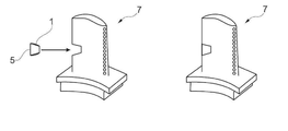
도 5 는 본 발명에 따른 모듈식 구조의 터빈 블레이드 또는 베인을 보여준다.
도 6 은 본 발명에 따른 브레이즈된 인서트를 가지는 터빈 블레이드 또는 베인을 보여준다.1 shows a damaged area of a turbine blade or vane after repair according to the prior art.
2 shows a damaged area of a turbine blade or vane after repair according to the invention.
3 shows a braze foil in a first embodiment variant according to the invention.
4 shows a braze foil in a second embodiment variant according to the invention.
5 shows a turbine blade or vane of a modular structure according to the invention.
6 shows a turbine blade or vane with a brazed insert according to the invention.
다음 본문에서, 본 발명은 예시적인 실시형태와 도면을 기초로 더 자세히 설명된다.In the following text, the invention is described in more detail on the basis of exemplary embodiments and figures.
도 1 은 종래 기술에 따른 종래의 브레이징 보수 방법 이후 손상된 부품 (7) 을 보수하기 위한 접합부 (6) 를 개략적으로 보여준다. 이 경우에, 부품 (7) 은 단결정 모재 (10), 더 정확히 말하면 CMSX4 (10 중량% 의 Co, 6.5 중량% 의 Cr, 6.5 중량% 의 Ta, 6 중량% 의 W, 5.6 중량% 의 Al, 2.9 중량% 의 Re, 1 중량% 의 Ti, 0.6 중량% 의 Mo, 0.1 중량% 의 Hf, 나머지 Ni) 로 만들어진 가스 터빈 블레이드 또는 베인이다. 접합부 (6) 는 종래 기술에 공지된 종래의 용융 스핀 프로세스로 제조되었는 종래의 브레이즈 호일 (1) 을 이용해 보수되었다. 브레이즈 재료의 화학 조성은 다음과 같은데, 즉 15 중량% 의 Cr, 7.25 중량% 의 Si, 1.4 중량% 의 B, 0.06 중량% 이하의 C, 나머지 Ni 이었다. 도 1 은 브레이즈될 간극 (6) 주위의 재결정화 구역 (9) 을 보여주는데, 모재 (10) 에 더 이상 단결정 미세조직이 없고, 즉 여기에서 모재 (10) 의 특성은 높은 요구와 크게 상이하다.1 shows schematically a joint 6 for repairing a
도 2 는 본 발명에 따른 브레이즈 호일로 본 발명에 따른 브레이징 보수 방법 후 부품 (7) 의 접합부 (6) 를 개략적으로 보여준다. 도 1 과 비교했을 때, 접합부 (6) 주위의 재결정화된 구역이 모재 (10) 에 없고, 즉 모재 (10) 는 또한 보수 후, 즉 접합부 (6) 가 브레이즈된 후 단결정 구조를 가지는 것을 명확히 알 수 있다. 이것에 대한 이유는 도 3 과 관련하여 설명된다.2 shows schematically the
도 3 은 본 발명에 따른 제 1 실시형태 변형예에서 브레이즈 호일 (1) 을 개략적으로 보여준다. 브레이즈 호일 (1) 은 초기에 또한 용융 스핀 프로세스에 의해 제조되었고, Ni 계, Co 계 또는 Ni-Co 계 화학 조성을 가지며 고온 브레이징에 적합하다. 본 발명에 따른 브레이즈 호일 (1) 은, 브레이즈 호일 (1) 의 상측과 하측이 나노미터 범위의 입자 크기를 가지는 금속성 Ni 계, Co 계 또는 Ni-Co 계 브레이즈 분말 (2) 의 필름으로 얇게 코팅되고, (최초) 브레이즈 호일 (1) 과 또한 브레이즈 분말 (2) 양자는 결정립계 안정화 원소, 예를 들어 합금 원소로서 B, C, Hf, Re, Zr 을 더 포함한다는 사실에 의해 구별된다. 본 발명과 관련하여, 여기에서 금속성은 합금 (Ni 계, Co 계 또는 Ni-Co 계) 과 비슷하다. 브레이즈 호일의 코팅은 분말 형태로, 페이스트로서 또는 현탁액으로서 적용될 수 있다.3 schematically shows a
구체적으로, 이 예시적인 실시형태에서 용융 스핀 프로세스에 의하여 제조된 브레이즈 호일 (1) 은 다음과 같은 재료 조성, 즉 15.2 중량% 의 Cr, 4 중량% 의 B, 0.06 중량% 의 C, 나머지 Ni 를 가졌다.Specifically, the
금속 브레이즈 분말 (2) 은 다음과 같은 조성, 즉 15 중량% 의 Cr, 10 중량% 의 Co, 5.5 중량% 의 Al, 3 중량% 의 Ta, 3 중량% 의 B, 0.15 중량% 의 Y, 나머지 Ni 를 가졌다. 분말 (2) 은 20 ~ 50 nm 의 입도 범위를 가졌고 도 3 의 좌측 상부에 나타낸 것처럼 얇은 필름으로서 약 5 층으로 호일의 상측과 하측에 적용되었다.The metal braze powder (2) has the following composition: 15 wt% Cr, 10 wt% Co, 5.5 wt% Al, 3 wt% Ta, 3 wt% B, 0.15 wt% Y, the rest Ni had. Powder (2) had a particle size range of 20-50 nm and was applied to the upper and lower sides of the foil in about 5 layers as a thin film as shown in the upper left of FIG.
본 발명에 따른 브레이즈 호일 (1) 에 관하여, 표면에 나노미터 크기의 입자 때문에, 용융 온도는 크게 감소되고 그 결과 재결정화의 확률이 동시에 감소되어서, 상기 브레이즈 호일은 단결정 또는 일방향 응고된 부품을 브레이징하는데 우수하게 사용될 수 있어서 유리하다. 하지만, 브레이징하는 동안 모재 (10) 에서 국부적 재결정화를 피할 수 없다면, 존재하는 결정립계 안정화 원소는 결정립계가 매우 효과적으로 안정화되는 것을 의미한다. 본 발명에 따른 브레이즈 호일 (1) 의 유동 거동은 매우 우수하고, 결과적으로 예를 들어 도 1 에 도시된 바와 같이, 브레이즈될 심지어 고르지 않은 간극 (6) 이 브레이즈 합금으로 최적으로 충전된다.With regard to the
본 발명에 따른 브레이즈 호일 (1) 이 종래의 주조 부품의 고온 브레이징에 또한 사용될 수 있음은 말할 필요도 없다.It goes without saying that the
적어도 하나의 용융점 강하제는, 통상의, 상업적으로 이용 가능한 브레이즈 합금 조성과 적어도 같은 함유량으로, 바람직하게 최대 약 2 배로, 합금 원소로서 브레이즈 호일 (1) 및/또는 나노 분말 (2) 에 부가적으로 존재할 수 있다. 예로서, 비율은 약 3 ~ 7 중량% 의 B, 최대 15 중량% 의 Si 및 최대 15 중량% 의 P 일 수 있다.The at least one melting point lowering agent is, in an amount of at least about twice the conventional, commercially available braze alloy composition, preferably up to about twice, in addition to the braze foil (1) and / or the nanopowder (2) as alloying elements. May exist. By way of example, the ratio may be about 3 to 7 wt% B, up to 15 wt% Si and up to 15 wt% P.
그러면 용융 온도 감소 및 용융점 강하제의 작용에 대한 비교적 작은 입도의 분말 입자 (2) 의 효과가 유리하게도 강화된다.The effect of the relatively small particle
도 4 는 본 발명에 따른 추가 실시형태 변형예에서 브레이즈 호일 (1) 을 개략적으로 보여준다. 도 3 에 도시된 변형예와 비교했을 때, 여기에서 모재 (10) 또는 모재의 유도체로 이루어진 용가재 입자 (4) 는 부가적으로 브레이즈 호일 (1) 의 코팅에 존재하고, 즉 나노 분말 (2) 이 용가재 입자 (4) 와 혼합된다. 용가재 입자 (4) 는 바람직하게 1 ~ 30 ㎛ 범위의 입도 및 전체 분말 혼합물에서 1 ~ 40 중량% 의 비율을 가진다. 용가재 입자 (4) 의 입도는 1 ~ 15 ㎛ 의 범위에 있고 분말 혼합물에서 용가재 입자 (4) 의 비율은 5 ~ 20 중량% 인 것이 유리하다. 따라서, 특히 비교적 넓은 브레이즈될 간극 (6) 을 브레이즈할 수 있고, 게다가 사용된 용가재 재료의 유형과 비율에 따라 브레이즈된 구역의 특성에 영향을 미칠 수 있다. 하지만, 존재하는 큰 용가재 입자 (4) 때문에, 따라서 그러면 브레이즈 재료는 둘러싸는 모재처럼 더 이상 단결정 형태로 또는 방향성을 가지고 응고되지 않음이 예상될 수 있다.4 schematically shows a
또한 용가재 입자 (4) 의 표면은 나노 분말 (2) 의 입자로 부가적으로 얇게 코팅될 수 있다 (도 4 의 상부 좌측 참조). 제 1 분말 성분 (2) 의 입자를 이용한 호일 (1) 의 상하측 코팅 및 용가재 입자 (4) 의 코팅은, 그것이 단지 1 층 내지 최대 10 층까지의 입자를 포함한다면, 그것이 그 후 매우 용이하게 부분적으로 용융되기 때문에 특히 유리하다.The surface of the
예로서, 바람직한 예시적인 실시형태에서, 단결정 Ni 계 초합금으로 만들어진 가스 터빈 블레이드 또는 베인 (부품 (7)) 이 작동 중 발생되는 손상 때문에 보수되어야 한다면, 손상된 부품 (7) 은 (용가재 입자 (4) 없이) 본 발명에 따른 브레이즈 호일 (1) 을 사용함으로써 보수된다. 접합부 (6) 의 선행하는 통상적인 세척 이후, 브레이즈 호일 (1) 은 접합부에 적용되고, 그 후 간단한 열 처리 (즉, 실온 (RT) 으로 중간 냉각 없음) 에 의해 용융되는데, 이것은 복수의 단계로 진행되고 최종적으로 실온 (RT) 으로 냉각되어서, 예를 들어 브레이즈 재료와 부품 (7) 의 둘러싸는 모재 (10) 사이에 일체형 결합이 확립되고, 응고된 브레이즈 재료는 둘러싸는 모재 (10) 와 동일한 단결정 또는 방향성 미세조직을 가진다. 여기에서 사용된 열 처리 (진공 노) 는 예로서 본 발명이 기초로 한 개념에 대해 언급되어야 하고: 가열 속도는 10 ~ 15 ℃/분이었고, 브레이즈 호일 (1) 의 표면에서 브레이즈 합금 페이스트의 휘발성 성분을 전소시키기 위해서 400 ℃ 에서 온도가 30 분 동안 일정하게 유지되었다. 노에서 균일한 온도 분포를 보장하도록, 온도는 930 ℃ 에서 30 분 동안 일정하게 유지되었다. 실제 브레이징 작동은 20 분 동안 1050 ℃ 에서 수행되었다. 그 후, 방향성 또는 단결정 응고가 가능하도록, 온도는 느리게 (1 ~ 3 ℃/분) 1,000 ℃ 로 감소되었고 10 시간 동안 일정하게 유지되었다. 그 다음에, 온도는 실온으로 빠르게 (약 30 ℃/분) 냉각되었다.By way of example, in a preferred exemplary embodiment, if a gas turbine blade or vane (part 7) made of single crystal Ni based superalloy has to be repaired due to damage occurring during operation, the
간단한 브레이징 프로세스 및 또한 브레이즈 재료의 낮은 용융 온도 때문에 비교적 낮은 브레이징 온도가 유리하다. 모재 (10) 에서 재결정화 위험은 단지 작고, 결정립계가 실제로 형성되어야 한다면 가능한 결정립계는 안정화된다.A relatively low brazing temperature is advantageous because of the simple brazing process and also the low melting temperature of the braze material. The risk of recrystallization in the
넓은 간극 (예컨대, 250 ㎛ 의 간극 너비) 이 브레이즈되는 경우에, 용가재 입자 (4) 가 브레이즈 호일 (1) 의 코팅에 존재한다면 어떠한 수축도 거의 없다. 하지만, 그러면 응고된 브레이즈 재료는 둘러싸는 모재와 동일한 단결정 또는 일방향 응고된 미세조직을 반드시 가질 필요는 없지만, 그 대신에 이것은 바람직하게 다결정 형태로 응고될 것이다.In the case where a wide gap (eg a gap width of 250 μm) is brazed, there is little shrinkage if the
브레이즈 합금의 다중 적용과 대응하는 다중 열 처리가 본 발명에 따른 방법에 요구되지 않으므로 유리하다.Multiple applications of braze alloys and corresponding multiple heat treatments are advantageous since they are not required for the method according to the invention.
본 발명은 생길 수 있는 결정립계가 안정화된 상태에서 재결정화의 위험을 최소화하면서 열 터보기계의 블레이드 또는 베인의 보수를 더 큰 부하 구역으로 연장하는 것을 가능하게 한다.The present invention makes it possible to extend the repair of the blades or vanes of a thermal turbomachine to a larger load zone while minimizing the risk of recrystallization with possible grain boundaries stabilized.
브레이즈 호일 (1) 의 상하측에서 나노미터 입도 범위의 브레이즈 분말 (2) 과 용융점 강하제의 존재로 인해, 금속 본드는 비교적 낮은 온도에서 달성된다. 금속 브레이즈 분말 입자로부터 용융점 강하제의 확산은 가스 터빈의 정비 중 중단된다. 재결정화가 시작되는 구역이 부품의 표면에 위치하고 단지 작은 치수를 가지므로, 열 처리 중 비교적 큰 브레이즈 합금 입자로부터 확산이 아직 완료되지 않았을지라도, 브레이징 사이클 중 결정립계 안정화 원소의 작은 확산 경로는 결정립계를 국부적으로 안정화시키기에 충분하다.Due to the presence of the
도 5 는 본 발명에 따른 추가의 예시적인 실시형태로서 모듈식 구조의 새로운 터빈 블레이드 또는 베인을 보여준다. 완성된 터빈 블레이드 또는 베인은 도 5 의 우측의 부분 도면에서 볼 수 있다. 큰 단결정 부품 (7) 을 제조하는 것은 어렵고 많은 비용이 들기 때문에, 단결정 또는 일방향 응고된 니켈계, 코발트계 또는 니켈-코발트계 초합금으로 만들어진 적어도 2 개의 부품 요소 (7.1 ; 7.2) 로 이루어진, 모듈식 구조의 부품 (7), 특히 가스 터빈 블레이드 또는 베인을 제조하기 위한 새로운 방법이 또한 필요하다. 도 5 의 좌측의 부분 도면에 따르면, 부품 (7.1) 은 블레이드 또는 베인 루트 (root) 인데, 여기에 부품 (7.2) (부품 (7.1) 에서 루트 부분이 생략된 메인 블레이드 또는 베인 부품) 을 수용하기 위한 개구가 배치된다. 부품 요소 (7.1 ; 7.2) 는 마주보게 놓이고 결함 없이 서로 연결되고 일체로 본딩될 표면 (8.1 ; 8.2) 을 가진다. 여기에서, 용가재 입자 (4) 없이 본 발명에 따른 브레이즈 호일 (1) 이 사용되는데, 이것은 연결되어야 하는 표면 (8.1 ; 8.2) 의 통상적인 선행하는 기계적 준비 이후 적어도 하나의 표면 (8.1 ; 8.2) 에 적용된다. 그 후, 부품 요소 (7.1) 는 정확한 끼움장착으로 부품 요소 (7.2) 상에 밀어지고, 적합하다면, 2 개의 부품 요소 (7.1 ; 7.2) 는 서로에 대해 밀어져서, 단지 약 120 ㎛ 의 최대 모세관 간극 너비가 여전히 존재한다. 그 후, 간단한 열 처리가 수행되고, 그동안 브레이즈 합금 (1) 이 용융되고 최종적으로 실온 (RT) 으로 냉각되어서, 예를 들어 브레이즈 재료와 부품 요소 (7.1 ; 7.2) 의 표면 (8.1 ; 8.2) 사이에 일체형 결합이 확립되고, 응고된 브레이즈 재료는 둘러싸는 모재 (10) 와 동일한 단결정 또는 일방향 미세조직을 가진다.5 shows a new turbine blade or vane of modular construction as a further exemplary embodiment according to the invention. The finished turbine blade or vane can be seen in the partial view on the right side of FIG. 5. Since it is difficult and expensive to manufacture the large
단결정 또는 일방향 응고된 초합금으로 만들어진 교체편 (5) 은 또한 단결정 또는 일방향 응고된 초합금으로 만들어진 손상된 부품 (7) 에 에피택시얼하게 접합될 수 있다 (도 6 참조). 손상된 재료가 부품 (7) 으로부터 분리된 후 그리고 연결되어야 하는 부품 (7) 과 교체편 (5) 표면의 통상적인 선행하는 기계적 준비 후, 용가재 입자 (4) 없이 본 발명에 따른 브레이즈 호일 (1) 이 연결되어야 하는 표면 중 적어도 하나에 적용된다. 예시적인 본 실시형태에서, 이것은 교체편 (5) 의 표면이다. 그 후, 교체편 (5) 은 적용된 브레이즈 호일 (1) 과 함께 부품 (7), 여기에서 가스 터빈 블레이드 또는 베인으로 삽입되고, 그 시점에서 손상된 재료는 이전에 제거되었고 (도 6 의 좌측에서 부분 도면의 화살표 참조), 적합하다면, 교체편과 부품은 서로에 대해 눌러져서, 단지 약 120 ㎛ 의 최대 모세관 간극 너비만 여전히 존재한다. 그 후, 브레이즈 재료는 간단한 다단 열 처리 (실온 (RT) 으로 중간 냉각 없음) 에 의해 용융된다. 다음에 실온 (RT) 으로 냉각하는 동안, 브레이즈 재료 및 부품 (7) 과 교체편 (5) 의 표면 사이에 일체형 본드가 형성되고, 응고된 브레이즈 재료는 둘러싸는 모재와 동일한 단결정 또는 방향성 미세조직을 가진다. 보수된 부품 (7) 은 도 6 의 우측에 부분 도면으로 도시된다.The
여기에서, 역시, 간단한 브레이징 프로세스만 요구되고 브레이즈 호일의 낮은 용융 온도 때문에 브레이징 온도는 비교적 낮으므로 특히 유리하다. 단지 작은 재결정화의 위험이 있다. Here, too, it is particularly advantageous because only a simple brazing process is required and the brazing temperature is relatively low because of the low melting temperature of the braze foil. There is only a small risk of recrystallization.
큰 용가재 입자가 브레이즈 호일의 코팅에 부가적으로 사용된다면 그리고/또는 높은 비율의 용가재 입자가 사용된다면, 이 경우 (모세관 균열부 너비를 초과하는 간격) 에 에피택시얼 미세조직이 예상되지 않을지라도, 부품 요소 사이의 큰 간격 (최대 500 ㎛) 이 또한 용이하게 브레이즈될 수 있다. 브레이즈 호일을 이용한 브레이즈될 표면 사이 간극의 균질한 충전은 낮은 브레이징 온도와 함께 달성되는데, 이것은 세그먼트의 고형 야금 연결부가 연결되도록 허용한다.If large filler metal particles are additionally used for the coating of the braze foil and / or if a high proportion of filler metal particles are used, then in this case (gap beyond the capillary crack width) no epitaxial microstructure is expected, Large gaps between the component elements (up to 500 μm) can also be easily brazed. Homogeneous filling of the gap between the surfaces to be brazed with the braze foil is achieved with a low brazing temperature, which allows the solid metallurgical connections of the segments to be connected.
브레이즈 호일의 용융 온도 감소 및 재결정화의 확률 감소와 같은 본 발명의 일반적인 효과는 또한 강, Cu 합금과 Al 합금을 브레이징하기 위한 Ag, Cu 및 Al 을 기초로 한 다른 분류의 브레이즈 합금에 대해 달성될 수 있다.The general effects of the present invention, such as reducing the melting temperature of the braze foil and reducing the probability of recrystallization, can also be achieved for other classes of braze alloys based on Ag, Cu and Al for brazing steel, Cu alloys and Al alloys. Can be.
1 브레이즈 호일
2 금속 브레이즈 분말 (나노미터 범위의 입도를 가짐)
4 용가재 입자
5 교체편
6 브레이즈될 간극
7 부품
7.1 ; 7.2 부품 요소
8.1 ; 8.2 마주보게 놓이고 연결될 표면
9 재결정화 구역
10 모재1 braze foil
2 metal braze powder (having a particle size in the nanometer range)
4 lobster particles
5 replacement
6 gap to be brazed
7 Parts
7.1; 7.2 Part Elements
8.1; 8.2 Surfaces to be Faced and Connected
9 Recrystallization Zone
10 base materials
Claims (13)
상기 브레이즈 호일 (1) 의 상측과 하측은 나노미터 범위의 입자 크기를 가지는 금속성 Ni 계, Co 계 또는 Ni-Co 계 브레이즈 분말 (2) 의 필름으로 얇게 코팅되고, 브레이즈 호일 (1) 과 또한 브레이즈 분말 (2) 양자는 합금 원소로서 결정립계 안정화 원소를 더 포함하는 것을 특징으로 하는 고온 브레이징용 브레이즈 호일 (1).An amorphous Ni-based, Co-based, or Ni-Co-based braze foil 1 for hot brazing produced by a melt spin process, wherein the braze foil 1 is placed on a hot brazing braze foil 1 having an upper side and a lower side. In
The upper and lower sides of the braze foil 1 are thinly coated with a film of metallic Ni, Co or Ni-Co based braze powder 2 having a particle size in the nanometer range, and the braze foil 1 and also the braze Both powders (2) are brazing foils for high temperature brazing, characterized in that they further comprise grain boundary stabilizing elements as alloy elements.
B, C, Hf, Re 와 Zr 로 이루어진 군에서의 적어도 1 종의 원소가 결정립계 안정화 원소로서 선택되는 것을 특징으로 하는 고온 브레이징용 브레이즈 호일 (1).The method of claim 1,
Braze foil for high temperature brazing (1), wherein at least one element in the group consisting of B, C, Hf, Re, and Zr is selected as a grain boundary stabilizing element.
상기 브레이즈 호일 (1) 및/또는 브레이즈 분말 (2) 은, 통상의, 상업적으로 이용 가능한 브레이즈 합금 조성과 적어도 같은 함유량으로, 적어도 하나의 용융점 강하제를 포함하는 것을 특징으로 하는 고온 브레이징용 브레이즈 호일 (1).3. The method according to claim 1 or 2,
The braze foil 1 and / or braze powder 2 comprises at least one melting point lowering agent in a content of at least the same as a conventional, commercially available braze alloy composition. One).
상기 용융점 강하제의 함유량은 통상의, 상업적으로 이용 가능한 브레이즈 합금 조성의 최대 약 2 배인 것을 특징으로 하는 고온 브레이징용 브레이즈 호일 (1).The method of claim 3, wherein
The brazing foil for high temperature brazing (1), wherein the content of the melting point lowering agent is at most about twice that of a conventional, commercially available braze alloy composition.
B, Si 와 P 로 이루어진 군에서의 적어도 1 종의 원소 또는 이들 원소의 조합물이 용융점 강하제로서 선택되는 것을 특징으로 하는 고온 브레이징용 브레이즈 호일 (1).The method according to claim 3 or 4,
Braze foil (1) for high temperature brazing, characterized in that at least one element or a combination of these elements in the group consisting of B, Si and P is selected as the melting point lowering agent.
붕소 (B) 의 비율은 약 3 ~ 7 중량% 이고, Si 의 비율은 최대 15 중량% 이고 P 의 비율은 최대 15 중량% 인 것을 특징으로 하는 고온 브레이징용 브레이즈 호일 (1).The method of claim 5, wherein
The proportion of boron (B) is about 3 to 7% by weight, the proportion of Si is at most 15% by weight and the proportion of P is at most 15% by weight.
상기 브레이즈 호일 (1) 의 코팅은 1 ~ 30 ㎛ 범위의 입도를 가지고 분말 혼합물에서 1 ~ 40 중량% 의 비율을 가지는 용가재 입자 (4) 를 더 포함하는 것을 특징으로 하는 고온 브레이징용 브레이즈 호일 (1). 7. The method according to any one of claims 1 to 6,
The coating of the braze foil 1 further comprises a filler metal particle 4 having a particle size in the range of 1 to 30 μm and having a proportion of 1 to 40% by weight in the powder mixture. ).
상기 용가재 입자 (4) 의 입도는 1 ~ 15 ㎛ 인 것을 특징으로 하는 고온 브레이징용 브레이즈 호일 (1).The method of claim 7, wherein
Particle size of the filler metal particles (4) is 1 ~ 15 ㎛ characterized in that the brazing foil for high temperature brazing (1).
상기 분말 혼합물에서 용가재 입자 (4) 의 비율은 5 ~ 20 중량% 인 것을 특징으로 하는 고온 브레이징용 브레이즈 호일 (1).The method of claim 7, wherein
Braze foil for high temperature brazing, characterized in that the proportion of filler metal particles (4) in the powder mixture is 5 to 20% by weight.
상기 용가재 입자 (4) 의 표면은 브레이즈 분말 (2) 의 입자로 얇게 코팅되는 것을 특징으로 하는 고온 브레이징용 브레이즈 호일 (1).The method of claim 7, wherein
The braze foil (1) for high temperature brazing, characterized in that the surface of the filler metal particles (4) is thinly coated with particles of the braze powder (2).
상기 브레이즈 분말 (2) 의 입자를 이용한 브레이즈 호일 (1) 의 상하측 코팅 및 용가재 입자 (4) 의 코팅은 단지 1 층, 최대 10 층까지의 브레이즈 분말 (2) 의 입자를 포함하는 것을 특징으로 하는 고온 브레이징용 브레이즈 호일 (1).11. The method according to claim 1 or 10,
The upper and lower coatings of the braze foil 1 and the coating of the filler metal particles 4 with the particles of the braze powder 2 are characterized in that they comprise particles of the braze powder 2 in only one layer, up to 10 layers. Braze foil for high temperature brazing (1).
상기 부품 요소 (7.1 ; 7.2) 는 마주보게 놓여 있으며 연결될 표면들 (8.1 ; 8.2) 을 가지고, 연결될 표면들 (8.1 ; 8.2) 의 통상적인 선행하는 기계적 준비 이후, 코팅된 브레이즈 호일 (1) 은 표면들 (8.1 ; 8.2) 중 적어도 하나에 도포되고, 그 후 부품 요소 (7.1 ; 7.2) 의 표면들 (8.1 ; 8.2) 은 정확한 끼움장착으로 서로 접합되어서 접합부 (6) 를 형성하고 함께 눌러지고, 그 후 브레이즈 재료는 간단한 열 처리에 의해 용융되고 실온으로 냉각되어서, 예를 들어 브레이즈 재료와 부품 요소 (7.1 ; 7.2) 의 표면들 (8.1 ; 8.2) 과의 사이에 일체형 결합이 확립되고, 접합부 (6) 에서의 응고된 브레이즈 재료는 둘러싸는 모재 (10) 와 동일한 단결정 또는 일방향 응고된 미세조직을 가지는 부품 (7), 특히 가스 터빈 블레이드 또는 베인을 제조 또는 보수하는 방법.At least two component elements made of a single crystal or unidirectional solidified nickel-based, cobalt-based or nickel-cobalt-based superalloy as the base material 10, using the braze foil 1 according to any one of claims 1-6. As a method for manufacturing or repairing parts (7), in particular gas turbine blades or vanes, comprising
The component elements (7.1; 7.2) are placed opposite and have surfaces (8.1; 8.2) to be joined, and after the conventional preceding mechanical preparation of the surfaces (8.1; 8.2) to be joined, the coated braze foil (1) (8.1; 8.2), and then the surfaces (8.1; 8.2) of the component elements (7.1; 7.2) are joined together with the correct fitting to form the joint (6) and pressed together, The braze material is then melted by a simple heat treatment and cooled to room temperature so that, for example, an integral bond is established between the braze material and the surfaces 8.1; 8.2 of the component element 7.1; 7.2 and the joint 6 The method of producing or repairing a component (7), in particular a gas turbine blade or vane, in which the solidified braze material in) has the same single crystal or unidirectional solidified microstructure as the surrounding substrate (10).
상기 교체편 (5) 은, 모재 (10) 로서 단결정 또는 일방향 응고된 니켈계, 코발트계 또는 니켈-코발트계 초합금으로 이루어지고, 연결될 부품 (7) 과 교체편 (5) 의 표면들의 통상적인 선행하는 기계적 준비 이후, 코팅된 브레이즈 호일 (1) 은 연결될 표면들중의 적어도 하나에 도포되고, 교체편 (5) 은 부품 (7) 안으로 도입되어 접합부 (6) 를 형성하고 선택적으로 안으로 눌러지고, 그 후 브레이즈 재료는 간단한 열 처리에 의해 용융되고 실온으로 냉각되어서, 예를 들어 브레이즈 재료와 부품 (7) 및 교체편 (5) 의 표면들과의 사이에 일체형 결합이 확립되고, 접합부 (6) 에서의 응고된 브레이즈 재료는 둘러싸는 모재 (10) 와 동일한 단결정 또는 일방향 응고된 미세조직을 가지는 부품 (7), 특히 가스 터빈 블레이드 또는 베인을 보수하는 방법.Using a braze foil (1) according to any one of claims 1 to 6, by inserting the replacement piece (5) in the component (7) to be repaired, a single crystal or one-way solidified nickel base as the base material (10), As a method of repairing a component (7), in particular a gas turbine blade or vane, made of cobalt-based or nickel-cobalt-based superalloy,
The replacement piece 5 consists of a single crystal or unidirectionally solidified nickel-based, cobalt-based or nickel-cobalt-based superalloy as the base material 10, and is a conventional prior art of the surfaces of the parts 7 and replacement pieces 5 to be connected. After mechanical preparation, the coated braze foil 1 is applied to at least one of the surfaces to be joined, and the replacement piece 5 is introduced into the part 7 to form the joint 6 and optionally pressed in, The braze material is then melted by simple heat treatment and cooled to room temperature so that, for example, an integral bond is established between the braze material and the surfaces of the component 7 and the replacement piece 5, and the joint 6 The method of repairing a component (7), in particular a gas turbine blade or vane, in which the solidified braze material has a single crystal or one-way solidified microstructure identical to the surrounding substrate (10).
Applications Claiming Priority (2)
| Application Number | Priority Date | Filing Date | Title |
|---|---|---|---|
| CH01204/11 | 2011-07-19 | ||
| CH01204/11A CH705321A1 (en) | 2011-07-19 | 2011-07-19 | Solder foil for high-temperature soldering and method of repairing or manufacturing components using this solder film. |
Publications (2)
| Publication Number | Publication Date |
|---|---|
| KR20130010878A true KR20130010878A (en) | 2013-01-29 |
| KR101613156B1 KR101613156B1 (en) | 2016-04-18 |
Family
ID=46395553
Family Applications (1)
| Application Number | Title | Priority Date | Filing Date |
|---|---|---|---|
| KR1020120079002A Expired - Fee Related KR101613156B1 (en) | 2011-07-19 | 2012-07-19 | Braze foil for high-temperature brazing and methods for repairing or producing components using said braze foil |
Country Status (6)
| Country | Link |
|---|---|
| US (1) | US8235275B1 (en) |
| EP (1) | EP2548686B1 (en) |
| KR (1) | KR101613156B1 (en) |
| CH (1) | CH705321A1 (en) |
| ES (1) | ES2452488T3 (en) |
| MX (1) | MX2012008231A (en) |
Families Citing this family (16)
| Publication number | Priority date | Publication date | Assignee | Title |
|---|---|---|---|---|
| CH700774A1 (en) * | 2009-03-31 | 2010-10-15 | Alstom Technology Ltd | Doppellotelement, process for its preparation and uses thereof. |
| WO2014013463A2 (en) * | 2012-07-18 | 2014-01-23 | Koninklijke Philips N.V. | Method of soldering an electronic component with a high lateral accuracy |
| US9174309B2 (en) * | 2012-07-24 | 2015-11-03 | General Electric Company | Turbine component and a process of fabricating a turbine component |
| US8640942B1 (en) * | 2013-03-13 | 2014-02-04 | Siemens Energy, Inc. | Repair of superalloy component |
| JP6275411B2 (en) * | 2013-08-09 | 2018-02-07 | 三菱重工業株式会社 | Brazing method |
| US9126279B2 (en) * | 2013-09-30 | 2015-09-08 | General Electric Company | Brazing method |
| DE102013222258A1 (en) * | 2013-10-31 | 2015-05-21 | MAHLE Behr GmbH & Co. KG | Process for producing a heat exchanger, in particular a sorption heat exchanger |
| EP3216554B1 (en) * | 2016-03-09 | 2020-05-06 | MTU Aero Engines GmbH | Component with wear- resistant openings and depressions and method for producing the same |
| CN110640354B (en) * | 2019-08-27 | 2022-03-04 | 北京康普锡威科技有限公司 | Preformed solder and preparation method thereof |
| US11565336B2 (en) * | 2019-11-15 | 2023-01-31 | Rolls-Royce North American Technologies Inc. | Method of selectively bonding braze powders to a surface |
| CN114799395B (en) * | 2022-03-29 | 2023-02-21 | 北京科技大学 | Vacuum brazing method of dissimilar nickel-based superalloys to improve joint strength stability |
| CN114769771B (en) * | 2022-03-29 | 2023-09-05 | 北京科技大学 | Nickel-based superalloy brazing processing technology capable of reducing weld microcrack defects |
| CN114769772B (en) * | 2022-03-29 | 2023-04-28 | 北京科技大学 | Vacuum brazing method for improving strength of GH3536/GH4738 alloy joint |
| KR102631599B1 (en) | 2023-08-28 | 2024-02-01 | 터보파워텍(주) | Method of repairing wide gap cracks in hot gas path parts for gas turbine using brazing |
| KR102942234B1 (en) | 2023-11-14 | 2026-03-19 | 두산에너빌리티 주식회사 | Brazing plug and method of manufacturing gas turbine parts using it |
| US20250326074A1 (en) * | 2024-04-18 | 2025-10-23 | Ge Infrastructure Technology Llc | Systems and methods for repairing machined slots in gas turbine components |
Family Cites Families (53)
| Publication number | Priority date | Publication date | Assignee | Title |
|---|---|---|---|---|
| US4745037A (en) * | 1976-12-15 | 1988-05-17 | Allied Corporation | Homogeneous, ductile brazing foils |
| US4228214A (en) * | 1978-03-01 | 1980-10-14 | Gte Products Corporation | Flexible bilayered sheet, one layer of which contains abrasive particles in a volatilizable organic binder and the other layer of which contains alloy particles in a volatilizable binder, method for producing same and coating produced by heating same |
| US4169744A (en) * | 1978-06-28 | 1979-10-02 | Western Gold And Platinum Company | Nickel-chromium-silicon alloy brazing foil |
| US4160854A (en) * | 1978-07-19 | 1979-07-10 | Western Gold & Platinum Co. | Ductile brazing foil for cast superalloys |
| US4381944A (en) | 1982-05-28 | 1983-05-03 | General Electric Company | Superalloy article repair method and alloy powder mixture |
| US4448618A (en) * | 1983-02-28 | 1984-05-15 | Allied Corporation | Nickel based brazing filler metals |
| US4801072A (en) * | 1984-08-10 | 1989-01-31 | Allied-Signal Inc. | Homogeneous, ductile brazing foils |
| EP0342506A1 (en) * | 1988-05-20 | 1989-11-23 | Lonza Ag | Amorphous or partially amorphous metal alloy |
| US5240491A (en) | 1991-07-08 | 1993-08-31 | General Electric Company | Alloy powder mixture for brazing of superalloy articles |
| DE4231338A1 (en) * | 1992-09-18 | 1994-03-24 | Emitec Emissionstechnologie | Method for soldering a metallic structure, in particular partial areas of a honeycomb body |
| JP3392484B2 (en) * | 1992-10-30 | 2003-03-31 | 昭和電工株式会社 | Aluminum material for brazing and method for producing the same |
| JP2592778B2 (en) * | 1994-03-18 | 1997-03-19 | 川崎重工業株式会社 | Copper alloy lining method |
| AT400692B (en) * | 1994-04-13 | 1996-02-26 | Plansee Ag | HART LOT |
| US5806751A (en) | 1996-10-17 | 1998-09-15 | United Technologies Corporation | Method of repairing metallic alloy articles, such as gas turbine engine components |
| US9868100B2 (en) * | 1997-04-04 | 2018-01-16 | Chien-Min Sung | Brazed diamond tools and methods for making the same |
| DE19714530A1 (en) | 1997-04-08 | 1998-10-15 | Asea Brown Boveri | Process for soldering directionally solidified or single-crystal components |
| US6283356B1 (en) | 1999-05-28 | 2001-09-04 | General Electric Company | Repair of a recess in an article surface |
| US6464128B1 (en) | 1999-05-28 | 2002-10-15 | General Electric Company | Braze repair of a gas turbine engine stationary shroud |
| US6187450B1 (en) | 1999-10-21 | 2001-02-13 | General Electric Company | Tip cap hole brazing and oxidation resistant alloy therefor |
| ATE283936T1 (en) | 2001-05-14 | 2004-12-15 | Alstom Technology Ltd | METHOD FOR ISOTHERMAL BRAZING OF SINGLE CRYSTALLINE OBJECTS |
| US6843823B2 (en) * | 2001-09-28 | 2005-01-18 | Caterpillar Inc. | Liquid phase sintered braze forms |
| US7416108B2 (en) | 2002-01-24 | 2008-08-26 | Siemens Power Generation, Inc. | High strength diffusion brazing utilizing nano-powders |
| US6968991B2 (en) | 2002-07-03 | 2005-11-29 | Honeywell International, Inc. | Diffusion bond mixture for healing single crystal alloys |
| JP2004082218A (en) * | 2002-07-05 | 2004-03-18 | Ishikawajima Harima Heavy Ind Co Ltd | Brazing material sheet and method for producing the same |
| WO2005002780A1 (en) * | 2003-07-07 | 2005-01-13 | Ishikawajima-Harima Heavy Industries Co., Ltd. | Brazing filler metal sheet and method for production thereof |
| DE10335947A1 (en) * | 2003-08-04 | 2005-03-17 | Vacuumschmelze Gmbh & Co. Kg | Copper brazing alloy and brazing method |
| US20080017694A1 (en) | 2003-09-24 | 2008-01-24 | Alexander Schnell | Braze Alloy And The Use Of Said Braze Alloy |
| US7775414B2 (en) * | 2003-10-04 | 2010-08-17 | Siemens Energy, Inc. | Consumable insert and method of using the same |
| JP4551082B2 (en) | 2003-11-21 | 2010-09-22 | 三菱重工業株式会社 | Welding method |
| US7363707B2 (en) | 2004-06-14 | 2008-04-29 | General Electric Company | Braze repair of shroud block seal teeth in a gas turbine engine |
| US7565996B2 (en) * | 2004-10-04 | 2009-07-28 | United Technologies Corp. | Transient liquid phase bonding using sandwich interlayers |
| JP5062985B2 (en) * | 2004-10-21 | 2012-10-31 | 新日鉄マテリアルズ株式会社 | High Al content steel plate with excellent workability and method for producing the same |
| CN102897061A (en) * | 2004-10-29 | 2013-01-30 | 白木工业株式会社 | Reclining device |
| US7335427B2 (en) * | 2004-12-17 | 2008-02-26 | General Electric Company | Preform and method of repairing nickel-base superalloys and components repaired thereby |
| JP4492342B2 (en) * | 2004-12-24 | 2010-06-30 | 日立電線株式会社 | Brazing clad material, brazing method using the same, and brazed product |
| US7279229B2 (en) | 2005-03-24 | 2007-10-09 | General Electric Company | Nickel-base braze material and method of filling holes therewith |
| JP2007009275A (en) * | 2005-06-30 | 2007-01-18 | Mitsui Mining & Smelting Co Ltd | Nickel particle manufacturing method, nickel particle obtained by the manufacturing method, and conductive paste using the nickel particle |
| DE102005039803A1 (en) * | 2005-08-22 | 2007-05-24 | Vacuumschmelze Gmbh & Co. Kg | Brazing foil on iron-nickel base and method for brazing |
| EP1759806B1 (en) | 2005-09-06 | 2011-10-26 | Siemens Aktiengesellschaft | Brazing process for repairing a crack |
| US7800230B2 (en) * | 2006-04-28 | 2010-09-21 | Denso Corporation | Solder preform and electronic component |
| DE102006036195B4 (en) * | 2006-08-01 | 2025-07-03 | Vacuumschmelze Gmbh & Co. Kg | Nickel-based brazing alloys and brazing processes |
| EP1930116A3 (en) | 2006-12-07 | 2010-06-23 | Turbine Overhaul Services Private Limited | Method of diffusion brazing with nonoparticle alloys |
| US8342386B2 (en) | 2006-12-15 | 2013-01-01 | General Electric Company | Braze materials and processes therefor |
| EP1949988A1 (en) | 2007-01-17 | 2008-07-30 | Siemens Aktiengesellschaft | Powder mixture with blocky powder, method for utilisation of the powder mixture and components |
| WO2008095531A1 (en) | 2007-02-06 | 2008-08-14 | Siemens Aktiengesellschaft | Brazing composition and brazing method for superalloys |
| EP1967313A1 (en) * | 2007-03-09 | 2008-09-10 | Siemens Aktiengesellschaft | Component and a solder |
| JP2008272763A (en) * | 2007-04-25 | 2008-11-13 | Ihi Corp | Clad sheet and method for producing the same |
| DE102007028275A1 (en) * | 2007-06-15 | 2008-12-18 | Vacuumschmelze Gmbh & Co. Kg | Brazing foil on an iron basis as well as methods for brazing |
| DE102007049508B4 (en) * | 2007-10-15 | 2022-12-01 | Vacuumschmelze Gmbh & Co. Kg | Nickel-based brazing foil and brazing process |
| EP2062672A1 (en) | 2007-11-20 | 2009-05-27 | Siemens Aktiengesellschaft | Wide gap brazing method |
| DE102008056578B4 (en) | 2008-11-10 | 2017-11-09 | Airbus Defence and Space GmbH | Method for producing an erosion protection layer for aerodynamic components and structures |
| US8414267B2 (en) | 2009-09-30 | 2013-04-09 | General Electric Company | Multiple alloy turbine rotor section, welded turbine rotor incorporating the same and methods of their manufacture |
| DE102010016367A1 (en) * | 2010-04-08 | 2011-10-13 | Vacuumschmelze Gmbh & Co. Kg | Brazed article and method of brazing two or more parts |
-
2011
- 2011-07-19 CH CH01204/11A patent/CH705321A1/en not_active Application Discontinuation
- 2011-09-14 US US13/232,109 patent/US8235275B1/en not_active Expired - Fee Related
-
2012
- 2012-07-06 ES ES12175452.7T patent/ES2452488T3/en active Active
- 2012-07-06 EP EP12175452.7A patent/EP2548686B1/en active Active
- 2012-07-13 MX MX2012008231A patent/MX2012008231A/en active IP Right Grant
- 2012-07-19 KR KR1020120079002A patent/KR101613156B1/en not_active Expired - Fee Related
Also Published As
| Publication number | Publication date |
|---|---|
| CH705321A1 (en) | 2013-01-31 |
| MX2012008231A (en) | 2013-02-07 |
| EP2548686B1 (en) | 2013-12-18 |
| EP2548686A1 (en) | 2013-01-23 |
| KR101613156B1 (en) | 2016-04-18 |
| US8235275B1 (en) | 2012-08-07 |
| ES2452488T3 (en) | 2014-04-01 |
Similar Documents
| Publication | Publication Date | Title |
|---|---|---|
| KR101613152B1 (en) | Braze alloy for high-temperature brazing and methods for repairing or producing components using said braze alloy | |
| KR101613156B1 (en) | Braze foil for high-temperature brazing and methods for repairing or producing components using said braze foil | |
| US7416108B2 (en) | High strength diffusion brazing utilizing nano-powders | |
| JP4264490B2 (en) | Nickel-based brazing material | |
| JP4060083B2 (en) | Nickel-based brazing filler metal and brazing repair method | |
| EP2868426B1 (en) | Braze alloy compositions and brazing methods for superalloys | |
| JP6875430B2 (en) | High gamma prime nickel-based superalloys, their use, and methods for making turbine engine components | |
| US9796048B2 (en) | Article and process for producing an article | |
| EP3345718B1 (en) | Structure braze repair of hard-to-weld superalloy components using diffusion alloy insert | |
| JP6595593B2 (en) | Method for manufacturing turbine engine component | |
| CN104923956A (en) | Weld filler for nickel-base superalloys | |
| CN112584956B (en) | Segment replacement of turbine airfoils with metal-brazed pre-sintered preforms | |
| KR102152601B1 (en) | Turbine blade manufacturing method | |
| KR20100091178A (en) | Joining and material application method for a workpiece having a workpiece region comprising a titanium aluminide alloy | |
| US20110154947A1 (en) | Brazing Composition and Brazing Method for Superalloys | |
| US7653996B2 (en) | Method of repairing a crack in a turbine component | |
| JP2018168851A5 (en) | ||
| JP2009502503A (en) | Method for repairing parts having base material of directional microstructure and the parts | |
| JP2017518184A (en) | Articles with multiple grain structures for use in high stress environments | |
| US20050064220A1 (en) | Oxidation-resistant coatings bonded to metal substrates, and related articles and processes | |
| EP1930116A2 (en) | Method of diffusion brazing with nonoparticle alloys | |
| US10668571B2 (en) | Nanoparticle powders, methods for forming braze pastes, and methods for modifying articles | |
| JP2006016671A (en) | Ni-based alloy member and manufacturing method thereof, turbine engine component, welding material and manufacturing method thereof | |
| US20080135604A1 (en) | Method of diffusion brazing with nanoparticle alloys | |
| JP7076948B2 (en) | Articles, components, and methods of making components |
Legal Events
| Date | Code | Title | Description |
|---|---|---|---|
| PA0109 | Patent application |
St.27 status event code: A-0-1-A10-A12-nap-PA0109 |
|
| PG1501 | Laying open of application |
St.27 status event code: A-1-1-Q10-Q12-nap-PG1501 |
|
| R17-X000 | Change to representative recorded |
St.27 status event code: A-3-3-R10-R17-oth-X000 |
|
| A201 | Request for examination | ||
| PA0201 | Request for examination |
St.27 status event code: A-1-2-D10-D11-exm-PA0201 |
|
| P11-X000 | Amendment of application requested |
St.27 status event code: A-2-2-P10-P11-nap-X000 |
|
| P13-X000 | Application amended |
St.27 status event code: A-2-2-P10-P13-nap-X000 |
|
| E902 | Notification of reason for refusal | ||
| PE0902 | Notice of grounds for rejection |
St.27 status event code: A-1-2-D10-D21-exm-PE0902 |
|
| P11-X000 | Amendment of application requested |
St.27 status event code: A-2-2-P10-P11-nap-X000 |
|
| P13-X000 | Application amended |
St.27 status event code: A-2-2-P10-P13-nap-X000 |
|
| E701 | Decision to grant or registration of patent right | ||
| PE0701 | Decision of registration |
St.27 status event code: A-1-2-D10-D22-exm-PE0701 |
|
| PN2301 | Change of applicant |
St.27 status event code: A-3-3-R10-R13-asn-PN2301 St.27 status event code: A-3-3-R10-R11-asn-PN2301 |
|
| GRNT | Written decision to grant | ||
| PR0701 | Registration of establishment |
St.27 status event code: A-2-4-F10-F11-exm-PR0701 |
|
| PR1002 | Payment of registration fee |
St.27 status event code: A-2-2-U10-U11-oth-PR1002 Fee payment year number: 1 |
|
| PG1601 | Publication of registration |
St.27 status event code: A-4-4-Q10-Q13-nap-PG1601 |
|
| PN2301 | Change of applicant |
St.27 status event code: A-5-5-R10-R11-asn-PN2301 |
|
| PN2301 | Change of applicant |
St.27 status event code: A-5-5-R10-R14-asn-PN2301 |
|
| LAPS | Lapse due to unpaid annual fee | ||
| PC1903 | Unpaid annual fee |
St.27 status event code: A-4-4-U10-U13-oth-PC1903 Not in force date: 20190412 Payment event data comment text: Termination Category : DEFAULT_OF_REGISTRATION_FEE |
|
| PC1903 | Unpaid annual fee |
St.27 status event code: N-4-6-H10-H13-oth-PC1903 Ip right cessation event data comment text: Termination Category : DEFAULT_OF_REGISTRATION_FEE Not in force date: 20190412 |
|
| R18-X000 | Changes to party contact information recorded |
St.27 status event code: A-5-5-R10-R18-oth-X000 |
|
| PN2301 | Change of applicant |
St.27 status event code: A-5-5-R10-R13-asn-PN2301 St.27 status event code: A-5-5-R10-R11-asn-PN2301 |
|
| R11 | Change to the name of applicant or owner or transfer of ownership requested |
Free format text: ST27 STATUS EVENT CODE: A-5-5-R10-R11-ASN-PN2301 (AS PROVIDED BY THE NATIONAL OFFICE) |
|
| R13 | Change to the name of applicant or owner recorded |
Free format text: ST27 STATUS EVENT CODE: A-5-5-R10-R13-ASN-PN2301 (AS PROVIDED BY THE NATIONAL OFFICE) |