KR20130000083A - Instructin queue control apparatus - Google Patents
Instructin queue control apparatus Download PDFInfo
- Publication number
- KR20130000083A KR20130000083A KR1020110060564A KR20110060564A KR20130000083A KR 20130000083 A KR20130000083 A KR 20130000083A KR 1020110060564 A KR1020110060564 A KR 1020110060564A KR 20110060564 A KR20110060564 A KR 20110060564A KR 20130000083 A KR20130000083 A KR 20130000083A
- Authority
- KR
- South Korea
- Prior art keywords
- instruction
- storage unit
- branch
- input terminal
- command
- Prior art date
- Legal status (The legal status is an assumption and is not a legal conclusion. Google has not performed a legal analysis and makes no representation as to the accuracy of the status listed.)
- Granted
Links
Images


Classifications
-
- G—PHYSICS
- G06—COMPUTING OR CALCULATING; COUNTING
- G06F—ELECTRIC DIGITAL DATA PROCESSING
- G06F9/00—Arrangements for program control, e.g. control units
- G06F9/06—Arrangements for program control, e.g. control units using stored programs, i.e. using an internal store of processing equipment to receive or retain programs
- G06F9/30—Arrangements for executing machine instructions, e.g. instruction decode
- G06F9/38—Concurrent instruction execution, e.g. pipeline or look ahead
- G06F9/3854—Instruction completion, e.g. retiring, committing or graduating
- G06F9/3856—Reordering of instructions, e.g. using queues or age tags
-
- G—PHYSICS
- G06—COMPUTING OR CALCULATING; COUNTING
- G06F—ELECTRIC DIGITAL DATA PROCESSING
- G06F1/00—Details not covered by groups G06F3/00 - G06F13/00 and G06F21/00
- G06F1/26—Power supply means, e.g. regulation thereof
- G06F1/32—Means for saving power
- G06F1/3203—Power management, i.e. event-based initiation of a power-saving mode
- G06F1/3234—Power saving characterised by the action undertaken
- G06F1/325—Power saving in peripheral device
- G06F1/3275—Power saving in memory, e.g. RAM, cache
-
- G—PHYSICS
- G06—COMPUTING OR CALCULATING; COUNTING
- G06F—ELECTRIC DIGITAL DATA PROCESSING
- G06F9/00—Arrangements for program control, e.g. control units
- G06F9/06—Arrangements for program control, e.g. control units using stored programs, i.e. using an internal store of processing equipment to receive or retain programs
- G06F9/22—Microcontrol or microprogram arrangements
- G06F9/26—Address formation of the next micro-instruction ; Microprogram storage or retrieval arrangements
-
- Y—GENERAL TAGGING OF NEW TECHNOLOGICAL DEVELOPMENTS; GENERAL TAGGING OF CROSS-SECTIONAL TECHNOLOGIES SPANNING OVER SEVERAL SECTIONS OF THE IPC; TECHNICAL SUBJECTS COVERED BY FORMER USPC CROSS-REFERENCE ART COLLECTIONS [XRACs] AND DIGESTS
- Y02—TECHNOLOGIES OR APPLICATIONS FOR MITIGATION OR ADAPTATION AGAINST CLIMATE CHANGE
- Y02D—CLIMATE CHANGE MITIGATION TECHNOLOGIES IN INFORMATION AND COMMUNICATION TECHNOLOGIES [ICT], I.E. INFORMATION AND COMMUNICATION TECHNOLOGIES AIMING AT THE REDUCTION OF THEIR OWN ENERGY USE
- Y02D10/00—Energy efficient computing, e.g. low power processors, power management or thermal management
Landscapes
- Engineering & Computer Science (AREA)
- Theoretical Computer Science (AREA)
- Software Systems (AREA)
- Physics & Mathematics (AREA)
- General Engineering & Computer Science (AREA)
- General Physics & Mathematics (AREA)
- Advance Control (AREA)
Abstract
본 발명의 명령어 큐 제어장치는 메모리로부터 저장된 명령어들을 명령어 큐 저장부로 명령어 페치될 때, 페치되는 명령어들 중 분기명령어가 있는 경우, 분기명령어가 발생하면 루프명령어들을 순차적으로 명령어 큐 저장부에 저장하고, 계속적으로 동일한 분기명령어가 실행되면 명령어 큐 저장부에 저장된 루프명령어들을 순차적으로 판독하여 분기명령어를 처리하도록 하여 분기명령어 처리시 메모리 접근을 할 필요가 없으므로, 메모리 접근에 따른 전력소모를 감소시킬 수 있다.The command queue control apparatus of the present invention sequentially stores loop instructions in a command queue storage when a branch instruction occurs when there are branch instructions among the fetched instructions when instructions are fetched from the memory into the instruction queue storage unit. If the same branch instruction is executed continuously, loop instructions stored in the instruction queue storage are sequentially read to process the branch instruction, thereby eliminating the need for memory access during branch instruction processing, thereby reducing power consumption due to memory access. have.

Description
본 발명은 명령어 큐 제어장치에 관한 것으로, 특히 메모리로부터 저장된 명령어들을 명령어 큐 저장부로 명령어 페치될 때, 페치되는 명령어들 중 분기명령어가 있는 경우, 분기명령어를 처리하기 위한 반복되는 루프 내의 루프명령어들의 수가 명령어 큐 저장부의 저장영역의 수보다 작고, 분기명령어가 발생하면 루프명령어들을 순차적으로 명령어 큐 저장부에 저장하고, 계속적으로 동일한 분기명령어가 실행되면 명령어 큐 저장부에 저장된 루프명령어들을 순차적으로 판독하여 분기명령어를 처리하도록 하여 분기명령어 처리시 메모리 접근을 할 필요가 없으므로, 메모리 접근에 따른 전력소모를 감소시킬 수 있는 명령어 큐 제어장치에 관한 것이다.The present invention relates to an instruction queue control apparatus, and more particularly, when instruction instructions fetched from memory into an instruction queue storage section, when there is a branch instruction among the fetched instructions, loop instructions in a repeated loop for processing the branch instruction. If the number is smaller than the storage area of the command queue storage unit, and branch instructions occur, the loop instructions are sequentially stored in the command queue storage unit. If the same branch instruction is executed continuously, the loop instructions stored in the command queue storage unit are read sequentially. The present invention relates to a command queue control apparatus capable of reducing power consumption due to memory access since the branch instruction is processed so that the memory does not need to be accessed when the branch instruction is processed.
일반적으로 중앙처리장치(Micro-Processor)는 메모리에 저장된 다수의 명령어들의 집합으로 이루어진 프로그램을 읽어 들여 이를 디코더(Decoder)에 의해 해석하고, 실행기에 의해 각 명령어에 해당하는 동작을 실행한다.In general, a microprocessor reads a program consisting of a plurality of sets of instructions stored in a memory, interprets the program by a decoder, and executes an operation corresponding to each instruction by an executor.
중앙처리장치의 실행성능을 개선하기 위하여, 파이프라인(pipeline) 구조를 채택하여 다중 명령어를 겹치는 방식으로 파이프 스테이지를 통하여 이동되도록 하여 다중 명령어를 동시에 처리하도록 한다.In order to improve the execution performance of the central processing unit, a pipeline structure is adopted so that multiple instructions can be moved through the pipe stage in an overlapping manner so that multiple instructions can be processed simultaneously.
일반적으로 파이프라인은 4개의 스테이지인 명령어 인출, 명령어 해독, 명령어 실행 및 실행된 결과값 저장들의 기능 유니트들로 나누어질 수 있으며, 각각의 파이프라인의 기능 유니트들은 자기만의 속도로 독립적으로 진행할 수 있도록 설계되며, 이를 위해 각각의 파이프라인의 기능 유니트들은 그 전의 기능 유니트로부터 온 데이터를 미리 저장하기 위한 임시저장소인 버퍼들을 구비한다.In general, a pipeline can be divided into four stages: functional units of instruction retrieval, instruction decoding, instruction execution, and execution result storage, and each pipeline's functional units can proceed independently at their own pace. To this end, the functional units of each pipeline have buffers, which are temporary storages for storing data from previous functional units in advance.
그러나, 각각의 기능 유니트들을 자기만의 속도로 독립적으로 진행할 수 있게 함으로써, 다양한 파이프라인 해저드(hazard), 특히 프로그램 계수기를 변경시키는 분기명령 등이 발생하면 실행중인 명령어와 그 다음의 명령어들은 정지되어야만 한다. However, by allowing each functional unit to proceed independently at its own speed, the execution of the next instruction and the subsequent ones must be stopped when various pipeline hazards, especially branch instructions that change the program counter, occur. do.
도 1은 종래의 명령어 큐 제어장치에 대한 구성도이고, 도 2는 분기명령을 갖는 프로그램의 일부 명령어들이 저장된 메모리의 구성도이고, 도 3a 내지 도 3c는 도 2에 따른 프로그램을 수행하기 위한 종래의 명령어 큐 저장부에 저장되는 과정을 도시한 도면이다.1 is a configuration diagram of a conventional command queue control apparatus, FIG. 2 is a configuration diagram of a memory in which some instructions of a program having a branch instruction are stored, and FIGS. 3A to 3C are conventional diagrams for executing a program according to FIG. 2. FIG. 4 is a diagram illustrating a process of storing a command queue storage unit of FIG.
도 1에 도시된 바와 같이, 이러한 분기명령에 의한 해저드 발생을 방지하기 위해, 종래의 경우 임시저장소로 명령어 큐 저정부(1)를 사용하고, 디코더(2)에 의해 분기명령이 발생하면 분기명령어의 주소인 분기명령어주소(TAG)와 분기명령어에 의해 분기되는 분기목적주소(TAD)를 각각 분기명령어주소저장부(3)와 분기목적주소저장부(4)에 저장하고, 메모리접근주소(ADR)와 분기명령어 주소(TAG)를 비교부(6)에 의해 비교하여 분기명령이 발생하면 분기예측신호(BP)가 활성화되어, 분기목적주소(TAD)에 위치한 메모리로부터 분기명령에 의해 실행되기 위한 루프 내의 루프명령어들을 순차적으로 명령어 큐 저장부(1)에 저장하도록 한다.As shown in Fig. 1, in order to prevent the occurrence of the hazard caused by the branch instruction, in the conventional case, the instruction
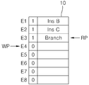
특정 프로그램을 수행하기 위해 도 2에 도시된 바와 같이 메모리에 저장된 제1일반명령어(Ins A), 제2일반명령어(Ins B), 제3일반명령어(Ins C), 분기명령어(Branch), 제4일반명령어(Ins D)에 대해 명령어 페치에 대해 살펴보면 다음과 같다. As shown in FIG. 2, a first general instruction Ins A, a second general instruction Ins B, a third general instruction Ins C, a branch instruction, and a first instruction are stored in the memory to execute a specific program. 4 Instruction fetch for general instruction (Ins D) is as follows.
종래의 명령어 큐 제어장치는 명령어페치 요구신호(IFR)가 활성화되면 기록포인트제어부(8)로부터 출력되는 기록포인트신호(WP)에 따라 명령어접근주소(ADR)가 증가함에 따라 명령어 큐 저장부(1)에는 도 3a에 도시된 바와 같이 세번째 엔트리(E3)부터 다섯번째 엔트리(E5)까지 순차적으로 메모리(100)로부터 페치된 제1일반명령어(Ins A), 제2일반명령어(Ins B), 제3일반명령어(Ins C), 분기명령어(Branch)가 저장된다. 파이프제어기로부터 출력되는 디코드요구신호(DRQ)가 활성화되면, 판독록포인트(RD)에 의해 명령어 큐 저장부(1)에 저장된 제1일반명령어(Ins A), 제2일반명령어(Ins B), 제3일반명령어(Ins C), 분기명령어(Branch)는 순차적으로 디코더(2)에 의해 명령어들이 해석되며, 분기명령어(Branch)에 의한 분기조건이 일치할 경우 분기가 발생하고, 처음 발생한 분기명령어에 대해서는 해저드가 발생한다.In the conventional command queue control apparatus, when the command fetch request signal IFR is activated, the command
그러나 도 3b에 도시된 바와 같이, 처음 발생한 분기명령어(Branch)에 의해 분기명령어주소(TAG)와 분기명령어에 의해 분기되는 분기목적주소(TAD)가 각각 분기명령어주소저장부(3)와 분기목적주소저장부(4)에 저장되어, 다음 동일한 분기명령어(Branch)가 발생하면, 비교부(6)에서 출력되는 분기예측신호(BP)가 활성화되어 메모리접근주소(ADR)는 데이터선택부(7)에 의해 분기목적주소(TAD)가 되어 제2일반명령어(Ins B)와, 제3일반명령어(Ins C), 분기명령어(Branch)들이 순차적으로 명령어 큐 저장부(1)에 저장되며, 제2일반명령어(Ins B)와, 제3일반명령어(Ins C), 분기명령어(Branch)들은 분기명령어에 의해 발생하는 루프명령어들로, 두번째 이후에서 발생하는 동일한 분기명령어인 경우 해저드가 발생하지 않는다.However, as shown in FIG. 3B, the branch instruction address TAG and the branch target address TAD branched by the branch instruction by the branch instruction branch that occurred first are the branch instruction
도 3c에 도시된 바와 같이 동일 분기명령어가 발생하여 계속적으로 동일한 루프가 발생하면, 메모리접근주소(ADR)에 따라 메모리(100)로 계속 접근해서 메모리(100)에 저장된 루프 명령어들을 명령어 큐 저장부(1)로 저장하게 된다.As shown in FIG. 3C, when the same branch instruction occurs and the same loop continues to occur, the instruction queue storage unit continuously accesses the
따라서, 종래의 명령어 큐 제어장치는 첫번째 분기명령어에 대해서는 해저드가 발생하나, 반복되는 동일 분기명령어에 대해서는 해저드가 발생하지 않는 장점은 있으나, 반복되는 동일 분기명령어가 발생될 때 마다 분기명령어를 처리하기 위해 계속해서 메모리에 접근하여 메모리에 저장된 루프명령어들을 명령어 큐 저장부에 기록하여야 하므로, 분기명령 실행시 전력소모가 커지는 문제점을 가지고 있다.Therefore, the conventional command queue control device has a merit that a hazard occurs for the first branch instruction, but a hazard does not occur for the same branch instruction that is repeated, but the branch instruction is processed whenever the same branch instruction is repeated. In order to continuously access the memory and write the loop instructions stored in the memory to the instruction queue storage unit, there is a problem in that power consumption increases when executing the branch instruction.
본 발명의 목적은 메모리로부터 저장된 명령어들을 명령어 큐 저장부로 명령어 페치될 때, 페치되는 명령어들 중 분기명령어가 있는 경우, 분기명령어를 처리하기 위한 반복되는 루프 내의 루프명령어들의 수가 명령어 큐 저장부의 저장영역의 수보다 작을 경우, 분기명령어가 발생하면 루프명령어들을 순차적으로 명령어 큐 저장부에 저장하고, 계속적으로 동일한 분기명령어가 실행되면 명령어 큐 저장부에 저장된 루프명령어들을 순차적으로 판독하여 분기명령어를 처리하도록 하여 분기명령어 처리시 메모리 접근을 할 필요가 없으므로, 메모리 접근에 따른 전력소모를 감소시킬 수 있는 명령어 큐 제어장치를 제공하는 데 있다.An object of the present invention is that when instructions are fetched from the memory into the instruction queue storage, when there is a branch instruction among the fetched instructions, the number of loop instructions in a repeated loop for processing the branch instruction is stored in the instruction queue storage portion. If the number of branches is less than 0, the loop instructions are stored in the instruction queue storage sequentially if a branch instruction occurs, and if the same branch instruction is executed continuously, the loop instructions stored in the instruction queue storage are sequentially read to process the branch instruction. Therefore, there is no need to access a memory when processing a branch instruction, and to provide a command queue control apparatus capable of reducing power consumption due to a memory access.
상기의 목적을 달성하기 위하여 본 발명의 명령어 큐 제어장치는 다수의 일반명령어 및 분기명령어들로 구성된 명령어들이 저장된 메모리와, 다수개의 명령어들이 각각 저장되는 다수개의 엔트리들로 구성되어 메모리접근주소에 따라 상기 메모리에 저장된 상기 명령어들중 일부 명령어들을 상기 메모리로부터 미리 페치하여 각각의 엔트리들에 저장하는 명령어 큐 저장부와, 상기 명령어 큐 저장부의 각각의 엔트리들에 저장된 명령어들을 판독하여 명령어들을 해석하는 디코더를 구비하여 상기 명령어 큐 저장부에 저장된 분기명령어에 의한 조건이 일치되면 분기목적주소로 분기되고, 분기목적주소에 위치한 메모리로부터 상기 분기명령어에 의해 실행되는 루프 내의 다수의 명령어들인 루프명령어들을 상기 명령어 큐 저장부로 저장하는 명령어 큐 제어장치에 있어서, 상기 명령어 큐 저장부에 저장된 명령어들을 상기 디코더로 판독하여, 상기 디코더에 의해 판독된 명령어가 분기명령어이면 분기명령어가 저장되어 있는 메모리의 주소인 분기명령어주소를 저장하는 분기명령어주소저장부; 상기 디코더에 의해 판독된 명령어가 분기명령어이면, 상기 분기명령어에 의해 분기되는 분기목적주소를 저장하는 분기목적주소저장부; 상기 분기명령어는 처음 발생한 분기명령어이고, 해당 분기명령어에 의한 조건이 일치되어 분기가 발생하고, 상기 분기명령어에 의해 실행되는 루프명령어들의 수가 상기 명령어 큐 저장부의 엔트리들의 수보다 작으면, 상기 메모리에 저장된 루프명령어들만이 순차적으로 상기 명령어 큐 저장부에 저장되는 필상태와, 상기 필상태에서 명령어 큐 저장부에 저장된 마지막 분기명령어에 따라 명령어 큐 저장부에 저장된 루프명령어들만을 상기 디코더로 판독하는 활성상태와, 상기 메모리에 저장된 일반명령어 또는 분기명령어들이 페치되어 상기 명령어 큐 저장부로 저장되는 정상상태를 갖는 상태제어신호를 출력하며, 상기 상태제어신호가 필상태일 때 상기 명령어 큐 저장부에 저장된 루프명령어들에 의해 상기 분기명령어와 다른 분기주소를 갖는 분기명령어이면 상기 필상태에서 정상상태로 천이되고, 상기 상태제어신호가 활성상태일 때에 상기 루프명령어들에 의해 상기 분기명령어와 다른 분기주소를 갖는 분기명령어이면 상기 활성상태에서 정상상태로 천이하는 상태제어부; 상기 분기명령어주소저장부에 저장된 분기명령어주소와 메모리접근주소를 수신하여 상기 분기명령어주소와 메모리접근주소를 비교하여 동일하면 활성화된 분기예측신호를 출력하는 제1비교부; 상기 분기예측신호가 비활성화되면 1씩 증가하고, 상기 분기예측신호가 활성화되면 상기 분기목적주소저장부에 저장된 분기목적주소를 갖는 메모리접근주소와, 상기 상태제어부의 상태제어신호가 정상상태이거나 필상태이면 상기 메모리접근주소에 따라 메모리에 저장된 명령어들을 상기 명령어 큐 저장부로 페치하고, 상기 상태제어신호가 활성상태이면 상기 메모리에 저장된 명령어들이 상기 명령어 큐 저장부로 페치되지 않도록 상기 메모리를 제어하는 명령어 접근 인에이블신호를 출력하는 메모리 접근 제어부; 명령어 페치 요구신호가 활성화되고, 상기 상태제어부의 상태제어신호가 정상상태이면, 1씩 증가하는 기록포인트를 출력하여 상기 기록포인트가 위치한 상기 명령어 큐 저장부의 특정 엔트리에 상기 메모리로부터 페치된 명령어가 저장되고, 명령어 페치 요구신호가 활성화되고, 상기 상태제어신호가 필상태이면 상기 기록포인트는 상기 명령어 큐 저장부의 첫번째 엔트리의 주소를 가진 후, 1씩 증가하여 상기 루프명령어들을 상기 명령어 큐 저장부의 첫번째 엔트리부터 순차적으로 저장하고, 상기 명령어 페치 요구신호가 활성화되고, 상기 상태제어신호가 활성상태이면 기록포인트는 현재의 기록포인트를 가지며, 상기 명령어 페치 요구신호가 비활성화되면 상기 메모리로부터 페치된 명령어들이 상기 명령어 큐 저장부로 기록되지 못하는 기록포인트 제어부; 및 디코더 요구신호가 활성화되면, 1씩 증가하는 판독포인트를 출력하여 상기 판독포인트에 따라 명령어 큐 저장부의 특정 엔트리에 저장된 명령어를 디코더로 판독되고, 상기 디코더 요구신호가 활성화되고 상기 상태제어부의 상태제어신호가 활성상태이고 판독포인트가 현재의 기록포인트에서 1을 감산한 값과 동일하면 상기 판독포인트는 상기 명령어 큐 저장부의 첫번째 엔트리에 저장된 명령어를 상기 디코더로 판독하고, 디코더 요구신호가 비활성화되면 상기 명령어 큐 저장부에 저장된 명령어들은 상기 디코더로 판독되지 못하는 판독포인트 제어부를 구비한 것을 특징으로 한다.In order to achieve the above object, the command queue control apparatus of the present invention includes a memory in which instructions composed of a plurality of general instructions and branch instructions, and a plurality of entries in which a plurality of instructions are stored, respectively, according to a memory access address. A command queue storage unit which fetches some of the instructions stored in the memory from the memory in advance and stores them in respective entries, and a decoder that reads the instructions stored in the respective entries of the command queue storage and interprets the instructions. A branch instruction address is branched to a branch target address if a condition of a branch instruction stored in the instruction queue storage unit is matched; Command to save to the queue storage unit In the queue control apparatus, a branch instruction word that reads instructions stored in the instruction queue storage unit to the decoder, and stores a branch instruction address which is an address of a memory in which a branch instruction is stored if the instruction read by the decoder is a branch instruction. Address storage; A branch target address storage unit for storing a branch target address branched by the branch instruction if the instruction read by the decoder is a branch instruction; The branch instruction is a branch instruction that is the first occurrence of a branch instruction, and if a condition occurs due to the matching branch instruction, a branch occurs, and if the number of loop instructions executed by the branch instruction is smaller than the number of entries in the instruction queue storage unit, the branch instruction is stored in the memory. Active to read only loop instructions stored in the instruction queue storage unit according to the fill state in which only stored loop instructions are sequentially stored in the instruction queue storage unit, and the last branch instruction stored in the instruction queue storage unit in the fill state. Outputs a state control signal having a state and a normal state in which general instructions or branch instructions stored in the memory are fetched and stored in the command queue storage unit, and a loop stored in the command queue storage unit when the state control signal is in a fill state. Instructions have a branch address different from the branch instruction If it is a branch instruction, the state transitions from the fill state to the normal state. If the branch control instruction has a branch address different from the branch instruction by the loop instructions when the state control signal is active, the state transitions from the active state to the normal state. Control unit; A first comparison unit configured to receive a branch instruction address and a memory access address stored in the branch instruction address storage unit and compare the branch instruction address and the memory access address to output an activated branch prediction signal; When the branch prediction signal is deactivated, the value increases by one. When the branch prediction signal is activated, the memory access address having the branch destination address stored in the branch purpose address storage unit and the state control signal of the state control unit are normal or required states. Fetches instructions stored in the memory to the command queue storage unit according to the memory access address, and if the state control signal is active, controls the memory to prevent the instructions stored in the memory from being fetched into the command queue storage unit. A memory access control unit for outputting an enable signal; When the command fetch request signal is activated and the state control signal of the state control unit is in a normal state, a write point that is incremented by one is output and a command fetched from the memory is stored in a specific entry of the command queue storage unit in which the record point is located. When the command fetch request signal is activated and the state control signal is in a fill state, the recording point has the address of the first entry of the command queue storage unit, and then increments by 1 to increment the loop commands to the first entry of the command queue storage unit. Sequentially store, and if the command fetch request signal is activated and the state control signal is active, the write point has a current write point, and if the command fetch request signal is deactivated, the commands fetched from the memory are Records that cannot be written to the queue store Agent control section; And when the decoder request signal is activated, outputs a readpoint incremented by one to read a command stored in a specific entry of the command queue storage unit to the decoder according to the readpoint, and the decoder request signal is activated to control the state of the state controller. If the signal is active and the read point is equal to the value of 1 subtracted from the current write point, the read point reads the command stored in the first entry of the command queue storage to the decoder, and if the decoder request signal is deactivated, the command The instructions stored in the queue storage unit may include a read point control unit that cannot be read by the decoder.
본 발명의 명령어 큐 제어장치는 메모리로부터 저장된 명령어들을 명령어 큐 저장부로 명령어 페치될 때, 페치되는 명령어들 중 분기명령어가 있는 경우, 분기명령어가 발생하면 루프명령어들을 순차적으로 명령어 큐 저장부에 저장하고, 계속적으로 동일한 분기명령어가 실행되면 명령어 큐 저장부에 저장된 루프명령어들을 순차적으로 판독하여 분기명령어를 처리하도록 하여 분기명령어 처리시 메모리 접근을 할 필요가 없으므로, 메모리 접근에 따른 전력소모를 감소시킬 수 있다.The command queue control apparatus of the present invention sequentially stores loop instructions in a command queue storage when a branch instruction occurs when there are branch instructions among the fetched instructions when instructions are fetched from the memory into the instruction queue storage unit. If the same branch instruction is executed continuously, loop instructions stored in the instruction queue storage are sequentially read to process the branch instruction, thereby eliminating the need for memory access during branch instruction processing, thereby reducing power consumption due to memory access. have.
도 1은 종래의 명령어 큐 제어장치에 대한 구성도,
도 2는 분기명령을 갖는 프로그램의 일부 명령어들이 저장된 메모리의 구성도,
도 3a 내지 도 3c는 도 2에 따른 프로그램을 수행하기 위한 종래의 명령어 큐 저장부에 명령어들이 저장되는 과정을 도시한 도면,
도 4는 본 발명의 명령어 큐 제어장치의 구성도,
도 5는 본 발명에 따른 상태제어부의 상태도,
도 6은 도 5에 따른 상태제어부의 구성도,
도 7은 본 발명에 따른 명령어 큐 저장부의 개략도,
도 8a 내지 도 8h는 도 2의 프로그램을 수행하기 위한 본 발명의 명령어 큐 저장부에 명령어들이 저장되는 과정을 도시한 도면이다.1 is a block diagram of a conventional command queue control device,
2 is a configuration diagram of a memory in which some instructions of a program having a branch instruction are stored;
3A to 3C are views illustrating a process of storing instructions in a conventional instruction queue storage unit for executing a program according to FIG. 2;
4 is a configuration diagram of a command queue control apparatus of the present invention;
5 is a state diagram of a state control unit according to the present invention;
6 is a configuration diagram of a state control unit according to FIG. 5;
7 is a schematic diagram of an instruction queue storage unit according to the present invention;
8A to 8H are diagrams illustrating a process of storing instructions in an instruction queue storage unit of the present invention for executing the program of FIG. 2.
이하, 첨부된 도면을 참조하여 본 발명의 명령어 큐 제어장치를 상세히 설명하고자 한다.Hereinafter, a command queue control apparatus of the present invention will be described in detail with reference to the accompanying drawings.
도 4 및 도 5에 도시된 바와 같이, 본 발명의 명령어 큐 제어장치는 다수의 일반명령어(Ins A, Ins B, Inc C, Ins D) 및 분기명령어(Branch)들로 구성된 명령어들이 저장된 메모리(100)와, 다수개의 명령어들이 각각 저장되는 다수개의 엔트리들(E1∼E8)로 구성되어 메모리접근주소(ADR)에 따라 메모리(100)에 저장된 명령어들 중 일부 명령어들을 메모리(100)로부터 미리 페치하여 각각의 엔트리들에 저장하는 명령어 큐 저장부(10)와, 명령어 큐 저장부(10)의 각각의 엔트리들에 저장된 명령어들을 판독하여 명령어들을 해석하는 디코더(20)와, 명령어 큐 저장부(10)에 저장된 명령어들을 디코더(20)로 판독하여, 디코더(20)에 의해 판독된 명령어가 분기명령어(Branch)이면 분기명령어가 저장되어 있는 메모리(100)의 주소인 분기명령어주소(TAG)를 저장하는 분기명령어주소저장부(30)와, 디코더(20)에 의해 판독된 명령어가 분기명령어이면, 분기명령어에 의해 분기되는 분기목적주소(TAD)를 저장하는 분기목적주소저장부(40)와, 정상상태(NST), 필상태(FST) 및 활성상태(AST)를 갖는 상태제어신호(ST)를 출력하는 상태제어부(50)와, 분기명령어주소저장부(20)에 저장된 분기명령어주소(TAG)와 메모리접근주소(ADR)를 수신하여 분기명령어주소(TAG)와 메모리접근주소(ADR)를 비교하여 동일하면 활성화된 분기예측신호(BP)를 출력하는 제1비교부(60)와, 메모리 접근 제어부(70)와, 기록포인트 제어부(80)와, 판독포인트 제어부(90)로 구성된다.As shown in Figure 4 and 5, the command queue control apparatus of the present invention is a memory (stored instructions) consisting of a plurality of general instructions (Ins A, Ins B, Inc C, Ins D) and branch instructions (Branch) 100 and a plurality of entries E1 to E8 in which a plurality of instructions are stored, respectively, to prefetch some of the instructions stored in the
상태제어부(50)는, 분기명령어(Branch)가 처음 발생한 분기명령어이고, 해당 분기명령어에 의한 조건이 일치되어 분기가 발생하고, 분기명령어(Branch)에 의해 실행되는 루프명령어들의 수가 명령어 큐 저장부(10)의 엔트리들의 수보다 작으면, 메모리(100)에 저장된 루프명령어들만이 순차적으로 상기 명령어 큐 저장부(10)에 저장되는 필상태(FST)와, 필상태(FST)에서 명령어 큐 저장부(10)에 저장된 마지막 분기명령어에 따라 명령어 큐 저장부(10)에 저장된 루프명령어들만을 디코더(20)로 판독하는 활성상태(AST)와, 메모리(100)에 저장된 일반명령어 또는 분기명령어들이 페치되어 명령어 큐 저장부(10)로 저장되는 정상상태(NST)를 갖는 상태제어신호(ST)를 출력한다. 또한, 상태제어부(50)는 상태제어신호(ST)가 필상태(FST)일 때 명령어 큐 저장부(10)에 저장된 루프명령어들에 의해 분기명령어와 다른 분기주소를 갖는 분기명령어이면 필상태(FST)에서 정상상태(NST)로 천이되고, 상태제어신호(ST)가 활성상태(AST)일 때에 루프명령어들에 의해 분기명령어와 다른 분기주소를 갖는 분기명령어이면 활성상태(AST)에서 정상상태(NST)로 천이한다.The state control unit 50 is a branch instruction in which a branch instruction (Branch) occurs for the first time, the branch is generated because the condition of the branch instruction is matched, and the number of loop instructions executed by the branch instruction branch is stored in the instruction queue storage unit. If less than the number of entries in (10), only the loop instructions stored in the
메모리 접근 제어부(70)는 분기예측신호(BP)가 비활성화되면 1씩 증가하고, 분기예측신호(BP)가 활성화되면 분기목적주소저장부(40)에 저장된 분기목적주소(TAD)를 갖는 메모리접근주소(ADR)를 출력한다. 또한, 메모리 접근 제어부(70)는 상태제어부(50)의 상태제어신호(ST)가 정상상태(NST)이거나 필상태(FST)이면 활성화되는 명령어 접근 인에이블신호(IAE)를 출력하여 메모리접근주소(ADR)에 따라 메모리(100)에 저장된 명령어들을 명령어 큐 저장부(10)로 페치하고, 상태제어신호(ST)가 활성상태(AST)이면 명령어 접근 인에이블신호(IAE)는 비활성화되어 메모리(100)에 저장된 명령어들이 명령어 큐 저장부(10)로 페치되지 않는다.When the branch prediction signal BP is inactivated, the memory
기록포인트 제어부(80)는 명령어 페치 요구신호(IFR)가 활성화되고, 상태제어부(50)의 상태제어신호(ST)가 정상상태(NST)이면, 1씩 증가하는 기록포인트(WP)를 출력하여 기록포인트(WP)가 위치한 명령어 큐 저장부(10)의 특정 엔트리에 메모리(100)로부터 페치된 명령어가 저장되고, 명령어 페치 요구신호(IFR)가 활성화되고, 상태제어신호(ST)가 필상태(FST)이면 기록포인트(WP)는 명령어 큐 저장부(10)의 첫번째 엔트리의 주소(ARE1)를 가진 후, 1씩 증가하여 루프명령어들을 명령어 큐 저장부(10)의 첫번째 엔트리(E1)부터 순차적으로 저장하고, 명령어 페치 요구신호(IFR)가 활성화되고, 상태제어신호(ST)가 활성상태(AST)이면 기록포인트(WP)는 현재의 기록포인트를 가지며, 명령어 페치 요구신호(IFR)가 비활성화되면 메모리(100)로부터 페치된 명령어들이 상기 명령어 큐 저장부(10)로 기록되지 못하도록 구성된다.When the command fetch request signal IFR is activated and the state control signal ST of the state controller 50 is in the normal state NST, the
판독포인트 제어부(90)는 디코더 요구신호(DRQ)가 활성화되면, 1씩 증가하는 판독포인트(RP)를 출력하여 판독포인트(RP)에 따라 명령어 큐 저장부(10)의 특정 엔트리에 저장된 명령어를 디코더(20)로 판독되고, 디코더 요구신호(DRQ)가 활성화되고 상태제어부(50)의 상태제어신호(ST)가 활성상태(AST)이고 판독포인트(RP)가 현재의 기록포인트(WP)에서 1을 감산한 값과 동일하면 판독포인트(RP)는 명령어 큐 저장부(10)의 첫번째 엔트리(E1)에 저장된 명령어를 디코더(20)로 판독하고, 디코더 요구신호(DRQ)가 비활성화되면 명령어 큐 저장부(10)에 저장된 명령어들은 디코더(20)로 판독되지 못하도록 구성된다.When the decoder request signal DRQ is activated, the
메모리 접근 제어부(70)는 메모리접근주소(ADR)를 수신하여, 메모리접근주소(ADR)를 1씩 증가시키는 메모리접근주소 카운터(71)와, 제1데이터선택부(MUX1)와, 제2데이터선택부(MUX2)로 구성된다.The memory
제1데이터선택부(MUX1)는 제1입력단(I0), 제2입력단(I1), 선택입력단(S) 및 출력단(O)을 가지며, 선택입력단(S)은 분기예측신호(BP)에 연결되고, 제1입력단(I0)은 메모리접근주소 카운터(71)의 출력과 연결되며, 제2입력단(I1)은 분기목적주소(TAD)에 연결되고, 출력단(O)으로 메모리접근주소(ADR)를 출력하고, 분기예측신호(BP)가 비활성화되면 메모리접근주소(ADR)는 제1입력단(I0)으로 입력되는 메모리접근주소 카운터(71)의 출력을 선택하고, 분기예측신호(BP)가 활성화되면 메모리접근주소(ADR)는 제2입력단(I1)으로 입력되는 분기목적주소(TAD)를 선택한다.The first data selection unit MUX1 has a first input terminal I0, a second input terminal I1, a selection input terminal S, and an output terminal O, and the selection input terminal S is connected to the branch prediction signal BP. The first input terminal I0 is connected to the output of the memory
제2데이터선택부(MUX2)는 제1입력단(I0), 제2입력단(I1), 선택입력단(S) 및 출력단(O)을 가지며, 선택입력단(S)은 상태제어신호(ST)에 연결되고, 제1입력단(I0)은 하이논리값을 갖고, 제2입력단(I1)은 로우논리값을 가지고, 출력단(O)으로 명령어접근 인에이블신호(IAE)를 출력하여, 상태제어신호(ST)가 정상상태(NST)이거나 필상태(FST)이면 명령어접근 인에이블신호(IAE)는 제1입력단(I0)으로 입력되는 하이논리값을 갖게되어 메모리접근주소(ADR)에 따라 메모리(100)에 저장된 명령어들을 명령어 큐 저장부(10)로 페치하고, 상태제어신호(ST)가 활성상태(AST)이면 명령어접근 인에이블신호(IAE)는 제2입력단(I1)으로 입력되는 로우논리값을 갖게되어 메모리(100)에 저장된 명령어들이 명령어 큐 저장부(10)로 페치되지 못하도록 구성된다.The second data selection unit MUX2 has a first input terminal I0, a second input terminal I1, a selection input terminal S, and an output terminal O, and the selection input terminal S is connected to the state control signal ST. The first input terminal I0 has a high logic value, the second input terminal I1 has a low logic value, and outputs a command access enable signal IEA to the output terminal O, thereby providing a state control signal ST. In the normal state (NST) or the fill state (FST), the command access enable signal IEA has a high logic value inputted to the first input terminal I0, and according to the memory access address ADR, the
기록포인트 제어부(80)는 기록포인트(WP)를 수신하여, 기록포인트(WP)를 1씩 증가시키는 기록포인트 카운터(81)와, 제3데이터선택부(MUX3)로 구성된다.The recording
제3데이터선택부(MUX3)는 제1입력단(I0), 제2입력단(I1), 선택입력단(S), 출력단(O) 및 인에이블단(EN)을 가지며, 인에이블단(EN)은 명령어 페치 요구신호(IFR)와 연결되고, 선택입력단(S)은 상태제어신호(ST)에 연결되고, 제1입력단(I0)은 기록포인트 카운터(81)의 출력과 연결되며, 제2입력단(I1)과 출력단(O)은 기록포인트(WP)와 연결되어, 명령어 페치 요구신호(IFR)가 비활성화되면 메모리(100)로부터 페치된 명령어들이 상기 명령어 큐 저장부(10)로 기록되지 못하고, 명령어 페치 요구신호(IFR)가 활성화되고, 상태제어신호(ST)가 정상상태(NST)이면, 출력단(O)으로 출력되는 기록포인트(WP)는 제1입력단(I0)으로 입력되는 기록포인트 카운터(81)의 출력을 선택하고, 명령어 페치 요구신호(IFR)가 활성화되고, 상태제어신호(ST)가 필상태(FST)이면 기록포인트(WP)는 명령어 큐 저장부(10)의 첫번째 엔트리의 주소(ARE1)로 변경된 후 기록포인트 카운터(81)의 출력을 선택하고, 명령어 페치 요구신호(IFR)가 활성화되고, 상태제어신호(ST)가 활성상태(AST)이면 출력단(O)으로 출력되는 기록포인트(WP)는 제2입력단(I1)으로 입력되는 기록포인트(WP)를 선택한다.The third data selector MUX3 has a first input terminal I0, a second input terminal I1, a selection input terminal S, an output terminal O, and an enable terminal EN, and the enable terminal EN The command fetch request signal IFR is connected, the selection input terminal S is connected to the state control signal ST, the first input terminal I0 is connected to the output of the
판독포인트 제어부(90)는 판독포인트(RP)를 수신하여, 판독포인트(RP)를 1씩 증가시키는 판독포인트 카운터(91)와, 기록포인트(WP)와 판독포인트(RP)를 수신하여, 판독포인트(RP)가 기록포인트(WP)에 1을 감산한 감산값과 동일하면 활성화되고, 판독포인트(RP)가 기록포인트(WP)에 1을 감산한 감산값과 동일하지 않으면 비활성화되는 비교신호(CP)를 출력하는 제2비교부(93)와, 제4데이터선택부(MUX4)와, 제5데이터선택부(MUX5)로 구성된다.The read
제4데이터선택부(MUX4)는 제1입력단(I0), 제2입력단(I1), 선택입력단(S), 출력단(O)을 가지며, 선택입력단(S)은 비교신호(CP)에 연결되고, 제1입력단(I0)은 판독포인트 카운터(91)의 출력과 연결되며, 제2입력단(I1)은 명령어 큐 저장부(10)의 첫번째 엔트리의 주소(ARE1)와 연결되어, 비교신호(CP)가 비활성화되면 출력단(O)은 제1입력단(I0)으로 입력되는 판독포인트 카운터(91)의 출력을 선택하고, 비교신호(CP)가 활성화되면 출력단(O)은 제2입력단(I2)으로 입력되는 명령어 큐 저장부(10)의 첫번째 엔트리의 주소(ARE1)를 선택한다.The fourth data selector MUX4 has a first input terminal I0, a second input terminal I1, a selection input terminal S, and an output terminal O, and the selection input terminal S is connected to the comparison signal CP. The first input terminal I0 is connected to the output of the
제5데이터선택부(MUX5)는 제1입력단(I0), 제2입력단(I1), 선택입력단(S), 출력단(O) 및 인에이블단(EN)을 가지며, 인에이블단(EN)은 디코더 요구신호(DRQ)와 연결되고, 선택입력단(S)은 상태제어부(50)의 출력인 상태제어신호(ST)에 연결되고, 제1입력단(I0)은 판독포인트 카운터(91)의 출력과 연결되며, 제2입력단(I1)은 제4데이터선택부(MUX4)의 출력단(O)과 연결되어, 디코더 요구신호(DRQ)가 비활성화되면 명령어 큐 저장부(10)에 저장된 명령어들은 디코더(20)로 판독되지 못하고, 디코더 요구신호(DRQ)가 활성화되고, 상태제어신호(ST)가 정상상태(NST) 또는 필상태(FST)이면 출력단(O)은 제1입력단(I0)으로 입력되는 판독포인트 카운터(91)의 출력을 선택하고, 디코더 요구신호(DRQ)가 활성화되고, 상태제어신호(ST)가 활성상태(AST)이면 출력단(O)은 제2입력단(I1)으로 입력되는 제4데이터선택부(MUS4)의 출력을 선택한다.The fifth data selector MUX5 has a first input terminal I0, a second input terminal I1, a selection input terminal S, an output terminal O, and an enable terminal EN, and the enable terminal EN It is connected to the decoder request signal DRQ, the selection input terminal S is connected to the state control signal ST, which is the output of the state control unit 50, and the first input terminal I0 is connected to the output of the
명령어 큐 저장부(10)는 각각의 엔트리들에 대응되는 유효필드(V)를 구비하여, 기록포인트(WP)에 의해 메모리(100)로부터 페치되는 명령어가 명령어 큐 저장부(10)의 특정 엔트리에 기록되면 해당 엔트리의 유효필드(V)는 활성화되고, 상태제어신호(ST)가 정상상태(NST)이고 판독포인트(RP)에 의해 명령어 큐 저장부(10)의 특정 엔트리에 저장된 명령어가 판독될 때 해당 엔트리의 유효필드(V)는 비활성화되고, 상태제어신호(ST)가 필상태(FST)나 활성상태(AST)이고 판독포인트(RP)에 의해 명령어 큐 저장부(10)의 특정 엔트리의 명령어가 판독될 때 해당 엔트리의 유효필드(V)는 계속 활성화된다.
The command
상기의 구성에 따른 본 발명인 명령어 큐 제어장치의 동작은 다음과 같다.Operation of the command queue control apparatus of the present invention according to the above configuration is as follows.
도 5 및 도 6에 도시된 바와 같이 본 발명에 따른 상태제어부(40)는 정상상태(NST)와 필상태(FST)와 활성상태(AST)의 세가지 상태를 갖는 상태제어신호(ST)를 출력한다.As shown in FIGS. 5 and 6, the
상태제어신호(ST)가 정상상태(NST)일 때에는 도 8a 내지 도 8c에 도시된 바와 같이, 메모리접근주소(ADR)에 의해 메모리(100)로부터 명령어들이 페치되어 페치된 명령어들이 기록포인트 제어부(80)의 출력인 기록포인트(WP)에 의해 명령어 큐 저장부(10)의 다수의 엔트리들(E1∼E8)로 저장되고, 명령어 큐 저장부(10)의 특정 엔트리에 명령어가 저장될 때에는 해당 엔트리에 대응되는 유효필드(V)는 활성화상태인 하이논리값을 갖게 되며, 판독포인트(RD)에 의해 명령어 큐 저장부(10)의 특정 엔트리에 저장된 명령어가 디코더(20)로 판독될 때에는 판독된 특정 엔트리의 유효필드(V)는 비활성화상태인 로우논리값을 갖게 된다. 유효필드(V)가 로우논리값을 가지면, 해당 엔트리에는 기록포인트(WP)에 의해 메모리(100)로부터 페치된 명령어를 저장할 수 있다. 즉, 유효필드(V)가 하이논리값을 가진 엔트리에 저장된 명령어는 유효한 명령어로, 해당 엔트리에는 새로운 명령어가 저장되지 못한다. When the state control signal ST is in the normal state NST, as illustrated in FIGS. 8A to 8C, instructions are fetched and fetched from the
상태제어신호(ST)가 필상태(NST)일 때에는 도 8d 내지 도 8f에 도시된 바와 같이 분기명령어(Branch)에 의한 조건이 일치되어 분기가 발생하여 분기명령어(Branch)에 의해 실행되는 루프 내의 루프명령어들인 제2일반명령어(Ins B), 제3일반명령어(Ins C), 분기명령어(Branch)의 명령어들이 메모리(100)로부터 페치되어 명령어 큐 저장부(10)의 첫번째 엔트리(E1)부터 순차적으로 명령어 큐 저장부(10)의 각각의 엔트리들에 저장되며, 필상태(FST)일 때에는 판독포인트(RD)에 의해 명령어 큐 저장부(10)에 저장된 명령어들이 디코더(20)로 판독될 때에는 유효필드(V)는 계속해서 하이논리값을 갖는다.When the state control signal ST is in the fill state NST, as shown in FIGS. 8D to 8F, a condition is met by a branch instruction branch, so that a branch occurs and is executed in the loop executed by the branch instruction branch. Instructions of the second general instruction Ins B, the third general instruction Ins C, and the branch instruction branch which are loop instructions are fetched from the
상태제어신호(ST)가 활성상태(AST)일 때에는 도 8g 및 도 8h에 도시된 바와 같이 필상태(FST)일 때의 명령어 큐 저장부(10)의 마지막 엔트리에 저장된 분기명령어(Branch)와 동일한 분기명령어가 발생하여 필상태(FST)일때 명령어 큐 저장부(10)에 저장된 루프명령어들인 제2일반명령어(Ins B), 제3일반명령어(Ins C), 분기명령어(Branch)의 명령어들을 디코더로 판독한다. 따라서, 상태제어신호(ST)가 활성상태(AST)일 때에는 분기명령어를 실행하기 위해 메모리(100)로부터 루프명령어를 페치하지 않고, 필상태(FST)일 때 명령어 큐 저장부(10)에 저장된 루프명령어들을 사용하도록 하여 메모리 접근을 하지 않는다.When the state control signal ST is in the active state AST, as shown in FIGS. 8G and 8H, the branch instruction branch stored in the last entry of the instruction
도 2에 도시된 메모리(100)에 저장된 분기명령어를 갖는 특정 프로그램을 수행하는 경우 본 발명의 명령어 큐 제어장치의 동작은 다음과 같다.When executing a specific program having a branch instruction stored in the
도 2에 도시된 바와 같이 이전에 분기명령어가 발생하지 않았다고 가정하고, 명령어접근주소(ADR)에 위치한 메모리(100)에는 제1일반명령어(Ins A)가 저장되어 있고, 순차적으로 메모리(100)에는 제2일반명령어(Ins B), 제3일반명령어(Ins C) 및 분기명령어(Branch)가 저장되어 있다고 가정한다.As shown in FIG. 2, it is assumed that a branch instruction has not previously occurred, and the first general instruction Ins A is stored in the
제1비교부(60)의 출력인 분기예측신호(BP)는 이전에 분기명령어가 발생하지 않았으므로 비활성화되어 로우논리값을 가지므로 제1데이터선택부(MUX1)의 출력인 메모리접근주소(ADR)는 메모리접근주소 카운터(71)에 의해 1씩 증가되고, 상태제어신호(ST)는 현재 정상상태(NST)이므로 제2데이터선택부(MUX2)의 출력인 명령어접근 인에이블신호(IAE)는 활성화되어 하이논리값을 갖는다.The branch prediction signal BP, which is the output of the
도 8a에 도시된 바와 같이, 명령어페치 요구신호(IFR)가 활성화되고, 현재의 기록포인트(WP)가 명령어 큐 저장부(10)의 세번째 엔트리(E3)에 위치했다면, 현재의 메모리접근주소(ADR)에 의해 메모리(100)에 저장된 제1일반명령어(Ins A)가 페치되어 명령어 큐 저장부(10)의 세번째 엔트리(E3)에 메모리(100)로 부터 페치된 제1일반명령어(Ins A)가 저장되며, 세번째 엔트리(E3)의 유효필드(V)는 활성화되어 하이논리값을 갖게된다. 메모리접근주소(ADR)는 메모리접근주소 카운터(71)에 의해 1씩 증가하고, 기록포인트(WP)도 기록포인트 카운터(81)에 의해 1씩 증가되어, 메모리(100)에 저장된 제2일반명령어(Ins B), 제3일반명령어(Ins C), 분기명령어(Branch), 제4일반명령어(Ins D)들이 순차적으로 명령어 큐 저장부(10)의 네번째 엔트리(E4)와, 다섯번째 엔트리(E5)와 여섯번째 엔트리(E6)와 일곱번째 엔트리(E7)에 각각 저장되며, 해당 엔트리들의 유효필드(V)는 모두 하이논리값을 갖는다.As shown in Fig. 8A, if the instruction fetch request signal IRR is activated and the current write point WP is located in the third entry E3 of the instruction
디코더요구신호(DRQ)가 활성화되면 판독포인트 제어부(90)의 출력인 판독포인트(RP)에 의해 명령어 큐 저장부(10)의 각 엔트리에 저장된 명령어들이 디코더(20)로 판독되게 되며, 도 8b에 도시된 바와 같이 현재의 판독포인트(RP)가 세번째 엔트리(E3)에 위치하면, 명령어 큐 저장부(10)의 세번째 엔트리(E3)에 저장된 제1일반명령어(Ins A)는 디코더(20)로 판독되며, 이때 유효필드(V)는 비활성화되어 로우논리값을 갖는다. When the decoder request signal DRQ is activated, the instructions stored in each entry of the instruction
즉, 상태제어신호(ST)가 정상상태(NST)일 때에는 판독포인트(RP)에 의해 명령어 큐 저장부(10)의 특정 엔트리에 저장된 명령어가 디코더(20)로 판독되면 해당 엔트리의 유효필드(V)는 비활성화시켜, 해당 엔트리에는 메모리(100)로부터 페치되는 명령어들을 저장할 수 있도록 해준다. 이와 같이 명령어 큐 저장부(10)는 유효필드(V)를 구비하여 첫번째 엔트리(E1)부터 마지막 엔트리(E8)까지 계속 순환시켜 명령어들을 저장할 수 있으며, 명령어 큐 저장부(10)의 기록포인트(WP)와 판독포인트(RP)는 파이프라인 처리를 위해 각각 독립적으로 동작한다.That is, when the state control signal ST is in the normal state NST, when a command stored in a specific entry of the instruction
도 8c에 도시된 바와 같이 판독포인트 카운터(91)에 의해 판독포인트(RP)가 1씩 증가함에 따라 명령어 큐 저장부(10)의 네번째 엔트리(E4)에 저장된 제2일반명령어(Ins B)와, 다섯번째 엔트리(E5)에 저장된 제3일반명령어(Ins C)와, 여섯번째 엔트리(E6)에 저장된 분기명령어(Branch)가 순차적으로 디코더(20)로 판독되고, 판독된 엔트리들의 유효필드(V)는 로우논리값을 갖는다.As shown in FIG. 8C, as the read point RP is increased by 1 by the
도 8a 내지 도 8c에서와 같이 명령어 큐 저장부(10)의 각 엔트리들로 메모리(100)로부터 페치된 명령어들이 저장되고, 판독포인트(RP)에 의해 명령어 큐 저장부(10)에 저장된 명령어들 중 처음 발생한 분기명령어(Branch)가 디코더(20)로 판독될 때까지는 도 5 및 도 6에 도시된 바와 같이 제6데이터선택부(MUX6)와 제10데이터선택부(MUX10)에 의해 상태제어부(50)의 출력인 상태제어신호(ST)는 정상상태(NST)를 출력하게 된다. As illustrated in FIGS. 8A to 8C, instructions fetched from the
제10데이터선택부(MUX10)의 선택입력단(S)은 이전의 상태제어신호(PST)가 입력되어, 이전의 상태제어신호(PST)가 정상상태(NST)일 때에는 제1입력단(I0)으로 입력되는 신호를 선택하여 출력단(O)으로 출력하고, 이전의 상태제어신호(PST)가 필상태(FST)이면 출력단(O)은 제2입력단(I1)으로 입력되는 신호를 선택하여 출력하고, 이전의 상태제어신호(PST)가 활성상태(AST)이면 출력단(O)은 제3입력단(I2)으로 입력되는 신호를 선택하여 출력한다.The selection input terminal S of the tenth data selecting unit MUX10 is inputted to the first input terminal I0 when the previous state control signal PST is input and the previous state control signal PST is in the normal state NST. The input signal is selected and output to the output terminal O. When the previous state control signal PST is the fill state FST, the output terminal O selects and outputs the signal input to the second input terminal I1. If the previous state control signal PST is in the active state AST, the output terminal O selects and outputs a signal input to the third input terminal I2.
따라서, 현재 상태제어신호(ST)는 정상상태(NST)이므로 제10데이터선택부(MUX10)의 선택입력단(S)으로 입력되는 이전 상태제어신호(PST)는 계속 정상상태(NST)이므로 제10데이터선택부(MUX10)는 제1입력단(I1)으로 입력되는 제6데이터선택부(MUX6)의 출력을 선택하고, 제6데이터선택부(MUX6)의 선택입력단(S)으로 입력된 디코더(20)에서 출력되는 필제어신호(FCN)는 비활성화되어 있으므로, 제6데이터선택부(MUX6)의 출력은 정상상태(NST)를 선택하게 되어, 도 8a 내지 도 8c는 상태제어신호(ST)는 정상상태(NST)인 경우이다.Therefore, since the current state control signal ST is the normal state NST, the previous state control signal PST inputted to the selection input terminal S of the tenth data selection unit MUX10 continues to be the normal state NST. The data selector MUX10 selects the output of the sixth data selector MUX6 input to the first input terminal I1, and the
판독포인트(RP)에 의해 명령어 큐 저장부(10)의 여섯번째 엔트리(E6)에 저장된 분기명령어(Branch)가 디코더(20)로 판독되면, 디코더(20)는 분기명령어인 것을 판단하고, 분기명령어이면 분기명령어주소저장부(30)에는 분기명령어가 저장된 메모리(100)의 주소인 분기명령어주소(TAG)를 저장하고, 분기목적주소저장부(40)에는 분기명령어에 의해 분기되어야 하는 메모리(100)의 주소인 분기목적주소(TAD)를 저장한다. When the branch instruction Branch stored in the sixth entry E6 of the instruction
디코더(20)는 여섯번째 엔트리(E6)에 저장된 명령어가 처음 발생한 분기명령어이고, 해당 분기명령어의 분기크기, 즉 분기명령어에 의해 실행되는 루프명령어들의 수가 명령어 큐 저장부(10)의 엔트리들의 수보다 큰지 작은지를 판단하여 루프명령어들의 수가 명령어 큐 저장부(10)의 엔트리들의 수보다 작으면 활성화된 필제어신호(FCN)를 출력한다.The
명령어 큐 저장부(10)의 엔트리들의 수가 8개이고, 분기명령어에 의해 실행되는 루프명령어들은 제2일반명령어(Ins B), 제3일반명령어(Ins C), 분기명령어(Branch)로 세개이므로, 필제어신호(FCN)는 하이논리값을 갖는 활성화상태가 된다.Since the number of entries in the instruction
도 5 및 도 6에 도시된 바와 같이, 하이논리값을 갖는 필제어신호(FCN)에 의해 제6데이터선택부(MUX6)와 제10데이터선택부(MUX10)에 의해 상태제어신호(ST)는 필상태(FST)가 된다.As shown in FIGS. 5 and 6, the state control signal ST is generated by the sixth data selector MUX6 and the tenth data selector MUX10 by the fill control signal FCN having a high logic value. The fill state (FST) is reached.
상태제어신호(ST)가 필상태(FST)이면, 명령어 큐 저장부(10)에 저장된 모든 명령어들은 지워지고, 유효필드(V)는 비활성화되어 명령어 큐 저장부(10)는 초기상태로 가게 되고, 기록포인터(WP)와 판독포인트(RP)는 각각 명령어 큐 저장부(10)의 첫번째 엔트리(E1)의 주소(ARE1)를 갖게 된다.If the state control signal ST is a fill state FST, all commands stored in the command
제1비교부(60)는 분기명령어주소저장부(30)로부터 출력되는 분기명령어주소(TAG)와 현재의 메모리접근주소(ADR)와 비교하여 동일하면 활성화된 분기예측신호(BP)를 출력하게 되며, 명령어 큐 저장부(10)의 여섯번째 엔트리(E6)에 분기명령어(Branch)가 페치될 때에는 메모리접근주소(ADR)는 분기명령어주소(TAG)와 동일하므로, 상태제어신호(ST)가 필상태(FST)의 초기시에는 분기예측신호(BP)는 활성화되어 메모리접근주소(ADR)는 제1데이터선택부(MUX1)에 의해 분기목적주소(TAD)가 되고, 제2데이터선택부(MUX2)의 출력인 명령어접근 인에이블신호(IAE)는 계속해서 활성화되어 있으므로, 도 8d에 도시된 바와 같이 분기목적주소(TAD)에 위치한 메모리(100)에 저장된 명령어인 제2일반명령어(Ins B)를 페치하여 명령어 큐 저장부(10)의 첫번째 엔트리(E1)에 페치된 제2일반명령어(Ins B)를 저장한다. 현재의 메모리접근주소(ADR)는 분기목적주소(TAD)이므로, 제1비교부(60)의 출력인 분기예측신호(BP)는 비활성화되어 메모리접근주소(ADR)는 분기목적주소(TAD)로부터 1씩 증가하게 되어, 도 8e에 도시된 바와 같이 분기명령어에 의해 실행되는 루프명령어들을 1씩 증가하는 기록포인트(WP)에 의해 순차적으로 명령어 큐 저장부(10)의 두번째 엔트리(E2)와 세번째 엔트리(E3)에 각각 제3일반명령어(Ins C)와 분기명령어(Branch)를 각각 저장한다.The
상태제어부(50)에서 출력되는 상태제어신호(ST)가 필상태(FST)일 때에는 명령어 큐 저장부(10)의 각 엔트리들에 저장된 명령어는 판독포인트(RP)에 디코더(20)로 판독되더라도 지워지지 않아야 하므로, 판독포인트(RP)에 의해 각 엔트리의 명령어들이 판독될 때에도 유효필드(V)는 계속 하이논리값을 갖도록 한다.When the state control signal ST output from the state control unit 50 is the fill state FST, the instructions stored in the respective entries of the instruction
따라서, 도 8e 및 도 8f에 도시된 바와 같이 판독포인트(RP)가 1씩 증가하여 명령어 큐 저장부(10)의 첫번째 엔트리(E1)에 저장된 제2일반명령어(Ins B)가 판독되더라도 첫번째 엔트리(E1)의 유효필드(V)는 하이논리값을 계속 가진다.Therefore, as shown in FIGS. 8E and 8F, even if the second general instruction Ins B stored in the first entry E1 of the instruction
상기와 동일하게 명령어 큐 저장부(10)의 두번째 엔트리(E2)에 저장된 제3일반명령어(Ins C)와 세번째 엔트리(E3)에 저장된 분기명령어(Branch)가 순차적으로 디코더(20)로 판독되며, 두번째 엔트리(E2)와 세번째 엔트리(E3)의 유효필드(V)는 계속해서 하이논리값을 유지한다.As described above, the third general instruction Ins C stored in the second entry E2 of the instruction
도 8f에 도시된 바와 같이 필상태(FST)에서 명령어 큐 저장부(10)의 세번째 엔트리(E3)에 저장된 분기명령어(Branch)가 판독포인트(RP)에 의해 디코더(20)로 판독되면, 분기명령어주소저장부(30)로 분기명령어주소(TAG)가 저장되고, 저장된 분기명령어주소(TAG)와 현재 메모리접근주소(ADR)는 동일하므로 제1비교부(60)의 출력인 분기예측신호(BP)는 활성화상태인 하이논리값을 갖게 된다.As shown in FIG. 8F, when the branch instruction Branch stored in the third entry E3 of the instruction
하이논리값을 갖는 분기예측신호(BP)에 의해 도 5 및 도 6에 도시된 바와 같이 제8데이터선택부(MUX8)와 제10데이터선택부(MUX10)에 의해 상태제어부(50)는 활성상태(AST)를 갖는 상태제어신호(ST)를 출력한다.As shown in FIGS. 5 and 6 by the branch prediction signal BP having a high logic value, the state controller 50 is activated by the eighth data selector MUX8 and the tenth data selector MUX10. The state control signal ST having (AST) is output.
상태제어신호(ST)가 활성상태(AST)일 때에는 제2데이터선택부(MUX2)의 출력인 명령어접근 인에이블신호(IAE)는 로우논리값을 갖는 비활성상태가 되어 메모리(100)에 저장된 명령어들이 명령어 큐 저장부(10)로 페치되지 않도록 하고, 제3데이터선택부(MUX3)에 의해 기록포인트(WP)는 그 전의 기록포인트를 갖도록 하여 기록포인트(WP)는 도 8g에 도시된 바와 같이 계속해서 명령어 큐 저장부(10)의 네번째 엔트리(E4)의 위치에 있게 된다. When the state control signal ST is in the active state AST, the command access enable signal IEA, which is an output of the second data selector MUX2, becomes an inactive state having a low logic value and stored in the
또한, 활성상태(AST)의 초기에는 판독포인트(RP)는 명령어 큐 저장부(10)의 첫번째 엔트리(E1)에 위치하므로 제2비교부(93)의 출력인 비교신호(CP)는 비활성화되어, 리드포인트 카운터(93)와, 제4데이터선택부(MUX4)와 제5데이터선택부(MUX5)에 의해 리드포인트(RP)는 1씩 증가한다. 도 8h에 도시된 바와 같이 1씩 증가하는 리드포인트(RP)에 의해 명령어 큐 저장부(10)의 첫번째 엔트리(E1)에 저장된 제2일반명령어(Ins B), 두번째 엔트리(E2)에 저장된 제3일반명령어(Ins C), 세번째 엔트리(E3)에 저장된 분기명령어(Branch)가 순차적으로 디코더(20)로 판독된다.In addition, since the read point RP is located at the first entry E1 of the instruction
명령어 큐 저장부(10)의 세번째 엔트리(E3)에 저장된 분기명령어(Branch)가 판독된 후, 현재의 리드포인트(RP)=현재의 기록포인트(WP)-1인 값을 가지므로, 제2비교부(93)의 출력인 비교신호(CP)는 하이논리값을 갖는 활성화상태가 되므로, 리드포인트(RP)는 제4데이터선택부(MUX4)와 제5데이터선택부(MUX5)에 의해 명령어 큐 저장부(10)의 첫번째 엔트리(E1)의 주소(ARE1)가 되어, 상태제어신호(ST)가 활성상태(AST)일 때에는 계속해서 루프명령어들인 제2일반명령어(Ins B), 제3일반명령어(Ins C), 분기명령어(Branch)들의 명령어들이 순차적으로 디코더(20)로 판독되며, 계속해서 분기명령어에 의한 동일한 루프명령어들이 판독처리되기 위해 루프명령어들이 저장된 각 엔트리의 유효필드(V)는 하이논리값을 갖는다.Since the branch instruction Branch stored in the third entry E3 of the instruction
만약 필상태(FST)에서 이전에 발생한 분기명령어와 다른 분기명령어가 발생하면, 디코더(20)는 다른 분기명령어임을 나타내는 다른분기명령발생신호(OB)를 활성화시키고, 하이논리값을 다른분기명령발생신호(OB)에 의해 도 6의 제7데이터선택부(MUX7)와, 제8데이터선택부(MUX8)과 제10데이터선택부(MUX10)에 의해 상태제어부(50)의 출력인 상태제어신호(ST)는 정상상태(NST)로 천이된다.If a branch instruction different from the previously generated branch instruction occurs in the fill state FST, the
또한, 상태제어신호(ST)가 활성상태(AST)에서 이전에 발생한 분기명령어와 다른 분기명령어가 발생하면, 디코더(20)의 출력인 다른분기명령발생신호(OB)가 활성화되어, 도 6의 제9데이터선택부(MUX9)와, 제10데이터선택부(MUX10)에 의해 상태제어부(50)의 출력인 상태제어신호(ST)는 정상상태(NST)로 천이된다.In addition, when a branch instruction different from the branch instruction previously generated in the active state AST is generated, the other branch instruction generation signal OB, which is the output of the
이와 같이 본 발명의 명령어 큐 제어장치는 상태제어신호(ST)가 정상상태(NST)일 때에는 종래와 동일하게 메모리(100)로부터 명령어들이 페치되어 명령어 큐 저장부(10)에 저장되고, 상태제어신호(ST)가 필상태(FST)일 때에는 메모리(100)로부터 분기명령어에 의해 분기되어 처리되어야 할 루프명령어들만을 명령어 큐 저장부(10)에 저장하고, 상태제어신호(ST)가 활성상태(AST)일 때에는 명령어 큐 저장부(10)에 저장된 루프명령어들을 디코더(20)로 판독하여 분기명령어를 처리하도록 하여, 종래와는 달리 분기명령어 처리를 위해 메모리(100)로부터 분기명령어 처리를 위한 루프명령어들을 페치할 필요가 없다.As described above, in the command queue control apparatus of the present invention, when the state control signal ST is in the normal state NST, the commands are fetched from the
Claims (5)
상기 명령어 큐 저장부(10)에 저장된 명령어들을 상기 디코더(20)로 판독하여, 상기 디코더(20)에 의해 판독된 명령어가 분기명령어(Branch)이면 분기명령어가 저장되어 있는 메모리(100)의 주소인 분기명령어주소(TAG)를 저장하는 분기명령어주소저장부(30);
상기 디코더(20)에 의해 판독된 명령어가 분기명령어이면, 상기 분기명령어에 의해 분기되는 분기목적주소(TAD)를 저장하는 분기목적주소저장부(40);
상기 분기명령어는 처음 발생한 분기명령어이고, 해당 분기명령어에 의한 조건이 일치되어 분기가 발생하고, 상기 분기명령어에 의해 실행되는 루프명령어들의 수가 상기 명령어 큐 저장부(10)의 엔트리들의 수보다 작으면, 상기 메모리(100)에 저장된 루프명령어들만이 순차적으로 상기 명령어 큐 저장부(10)에 저장되는 필상태(FST)와, 상기 필상태(FST)에서 명령어 큐 저장부(10)에 저장된 마지막 분기명령어에 따라 명령어 큐 저장부(10)에 저장된 루프명령어들만을 상기 디코더(20)로 판독하는 활성상태(AST)와, 상기 메모리(100)에 저장된 일반명령어 또는 분기명령어들이 페치되어 상기 명령어 큐 저장부(10)로 저장되는 정상상태(NST)를 갖는 상태제어신호(ST)를 출력하며, 상기 상태제어신호(ST)가 필상태(FST)일 때 상기 명령어 큐 저장부(10)에 저장된 루프명령어들에 의해 상기 분기명령어와 다른 분기주소를 갖는 분기명령어이면 상기 필상태(FST)에서 정상상태(NST)로 천이되고, 상기 상태제어신호(ST)가 활성상태(AST)일 때에 상기 루프명령어들에 의해 상기 분기명령어와 다른 분기주소를 갖는 분기명령어이면 상기 활성상태(AST)에서 정상상태(NST)로 천이하는 상태제어부(50);
상기 분기명령어주소저장부(20)에 저장된 분기명령어주소(TAG)와 메모리접근주소(ADR)를 수신하여 상기 분기명령어주소(TAG)와 메모리접근주소(ADR)를 비교하여 동일하면 활성화된 분기예측신호(BP)를 출력하는 제1비교부(60);
상기 분기예측신호(BP)가 활성화되면 상기 분기목적주소저장부(40)에 저장된 분기목적주소(TAD)를 가지며, 상기 분기예측신호(BP)가 비활성화되면 1씩 증가하는 메모리접근주소(ADR)와, 상기 상태제어부(50)의 상태제어신호(ST)가 정상상태(NST)이거나 필상태(FST)이면 상기 메모리접근주소(ADR)에 따라 메모리(100)에 저장된 명령어들을 상기 명령어 큐 저장부(10)로 페치하고, 상기 상태제어신호(ST)가 활성상태(AST)이면 상기 메모리(100)에 저장된 명령어들이 상기 명령어 큐 저장부(10)로 페치되지 않도록 상기 메모리(100)를 제어하는 명령어 접근 인에이블신호(IAE)를 출력하는 메모리 접근 제어부(70);
명령어 페치 요구신호(IFR)가 활성화되고, 상기 상태제어부(50)의 상태제어신호(ST)가 정상상태(NST)이면, 1씩 증가하는 기록포인트(WP)를 출력하여 상기 기록포인트(WP)가 위치한 상기 명령어 큐 저장부(10)의 특정 엔트리에 상기 메모리(100)로부터 페치된 명령어가 저장되고, 명령어 페치 요구신호(IFR)가 활성화되고, 상기 상태제어신호(ST)가 필상태(FST)이면 상기 기록포인트(WP)는 상기 명령어 큐 저장부(10)의 첫번째 엔트리의 주소(ARE1)를 가진 후, 1씩 증가하여 상기 루프명령어들을 상기 명령어 큐 저장부(10)의 첫번째 엔트리(E1)부터 순차적으로 저장하고, 상기 명령어 페치 요구신호(IFR)가 활성화되고, 상기 상태제어신호(ST)가 활성상태(AST)이면 기록포인트(WP)는 현재의 기록포인트를 가지며, 상기 명령어 페치 요구신호(IFR)가 비활성화되면 상기 메모리(100)로부터 페치된 명령어들이 상기 명령어 큐 저장부(10)로 기록되지 못하는 기록포인트 제어부(80); 및
디코더 요구신호(DRQ)가 활성화되면, 1씩 증가하는 판독포인트(RP)를 출력하여 상기 판독포인트(RP)에 따라 명령어 큐 저장부(10)의 특정 엔트리에 저장된 명령어를 디코더(20)로 판독되고, 상기 디코더 요구신호(DRQ)가 활성화되고 상기 상태제어부(50)의 상태제어신호(ST)가 활성상태(AST)이고 판독포인트(RP)가 현재의 기록포인트(WP)에서 1을 감산한 값과 동일하면 상기 판독포인트(RP)는 상기 명령어 큐 저장부(10)의 첫번째 엔트리(E1)에 저장된 명령어를 상기 디코더(20)로 판독하고, 디코더 요구신호(DRQ)가 비활성화되면 상기 명령어 큐 저장부(10)에 저장된 명령어들은 상기 디코더(20)로 판독되지 못하는 판독포인트 제어부(90)를 구비한 것을 특징으로 하는 명령어 큐 제어장치.
The memory 100 includes a plurality of general instructions and branch instructions, and includes a plurality of entries E1 to E8 in which a plurality of instructions are stored, respectively, according to a memory access address ADR. Command queue storage unit 10 for pre-fetching some of the commands stored in the pre-fetched from the memory 100 and storing them in respective entries, and stored in respective entries of the command queue storage unit 10. A decoder 20 which reads the instructions and interprets the instructions and branches to a branch destination address if a condition by a branch instruction stored in the instruction queue storage unit 10 is matched, and branches from the memory located at the branch purpose address. In the command queue control apparatus for storing loop commands, which are a plurality of instructions in a loop executed by the command queue storage unit,
The instructions stored in the instruction queue storage unit 10 are read by the decoder 20, and if the instruction read by the decoder 20 is a branch instruction, the address of the memory 100 in which the branch instruction is stored. A branch instruction address storage unit 30 for storing the branch instruction instruction address TAG;
A branch target address storage unit (40) for storing a branch target address (TAD) branched by the branch instruction if the instruction read by the decoder (20) is a branch instruction;
The branch instruction is a branch instruction that is the first occurrence of a branch instruction, and if a condition occurs by the branch instruction, a branch occurs, and the number of loop instructions executed by the branch instruction is smaller than the number of entries in the instruction queue storage unit 10. Only the loop instructions stored in the memory 100 are sequentially stored in the command queue storage unit 10 and the last branch stored in the command queue storage unit 10 in the fill state FST. An active state AST for reading only loop instructions stored in the instruction queue storage unit 10 by the decoder 20 according to an instruction, and general instructions or branch instructions stored in the memory 100 are fetched to store the instruction queue. Outputs a state control signal ST having a normal state NST stored in the unit 10, and is stored in the command queue storage unit 10 when the state control signal ST is a fill state FST. Command For example, if the branch instruction has a branch address different from the branch instruction, the branch instruction transitions from the fill state (FST) to the normal state (NST), and the loop instructions when the state control signal (ST) is active (AST). A state control unit (50) for transitioning from the active state (AST) to the normal state (NST) if the branch instruction has a branch address different from the branch instruction by the;
Receives a branch instruction address TAG and a memory access address ADR stored in the branch instruction address storage unit 20 and compares the branch instruction address TAG and the memory access address ADR. A first comparator 60 for outputting a signal BP;
When the branch prediction signal BP is activated, the branch destination address TAD is stored in the branch purpose address storage unit 40. When the branch prediction signal BP is inactivated, the memory access address ADR increases by one. If the state control signal ST of the state controller 50 is a normal state NST or a fill state FST, the command queue storage unit stores the instructions stored in the memory 100 according to the memory access address ADR. If the status control signal ST is active (AST), the memory 100 is controlled so that the commands stored in the memory 100 are not fetched into the command queue storage unit 10. A memory access control unit 70 for outputting an instruction access enable signal IEA;
When the command fetch request signal IFR is activated and the state control signal ST of the state controller 50 is in the normal state NST, the write point WP is incremented by one to output the write point WP. A command fetched from the memory 100 is stored in a specific entry of the command queue storage unit 10 in which is located, an instruction fetch request signal IFR is activated, and the state control signal ST is in a fill state FST. ), The write point WP has the address ARE1 of the first entry of the command queue storage unit 10, and then increases by 1 to increase the loop commands to the first entry E1 of the command queue storage unit 10. And sequentially store the command fetch request signal IFR, and if the state control signal ST is active, the write point WP has a current write point, and the command fetch request When the signal IFR is deactivated, the memory 100 returns to the memory 100. Emitter recording point control unit 80 the fetched instructions are not being written to the instruction queue storage unit 10; And
When the decoder request signal DRQ is activated, the decoder 20 outputs a read point RP incremented by one to read the command stored in a specific entry of the command queue storage unit 10 into the decoder 20 according to the read point RP. When the decoder request signal DRQ is activated, the state control signal ST of the state control unit 50 is the active state AST, and the read point RP subtracts 1 from the current recording point WP. If the value is the same, the read point RP reads the command stored in the first entry E1 of the command queue storage unit 10 to the decoder 20, and if the decoder request signal DRQ is deactivated, the command queue. Instruction queue control apparatus characterized in that it comprises a read point control unit (90) that the instructions stored in the storage unit (10) cannot be read by the decoder (20).
메모리접근주소(ADR)를 수신하여, 상기 메모리접근주소(ADR)를 1씩 증가시키는 메모리접근주소 카운터(71);
제1입력단(I0), 제2입력단(I1), 선택입력단(S) 및 출력단(O)을 가지며, 선택입력단(S)은 상기 분기예측신호(BP)에 연결되고, 제1입력단(I0)은 상기 메모리접근주소 카운터(71)의 출력과 연결되며, 제2입력단(I1)은 분기목적주소(TAD)에 연결되고, 출력단(O)으로 메모리접근주소(ADR)를 출력하고, 상기 분기예측신호(BP)가 비활성화되면 상기 메모리접근주소(ADR)는 상기 제1입력단(I0)으로 입력되는 메모리접근주소 카운터(71)의 출력을 선택하고, 상기 분기예측신호(BP)가 활성화되면 상기 메모리접근주소(ADR)는 상기 제2입력단(I1)으로 입력되는 분기목적주소(TAD)를 선택하는 제1데이터선택부(MUX1); 및
제1입력단(I0), 제2입력단(I1), 선택입력단(S) 및 출력단(O)을 가지며, 선택입력단(S)은 상기 상태제어신호(ST)에 연결되고, 제1입력단(I0)은 하이논리값을 갖고, 제2입력단(I1)은 로우논리값을 가지고, 출력단(O)으로 명령어접근 인에이블신호(IAE)를 출력하여, 상기 상태제어신호(ST)가 정상상태(NST)이거나 필상태(FST)이면 상기 명령어접근 인에이블신호(IAE)는 상기 제1입력단(I0)으로 입력되는 하이논리값을 갖게되어 메모리접근주소(ADR)에 따라 상기 메모리(100)에 저장된 명령어들을 상기 명령어 큐 저장부(10)로 페치하고, 상기 상태제어신호(ST)가 활성상태(AST)이면 상기 명령어접근 인에이블신호(IAE)는 상기 제2입력단(I1)으로 입력되는 로우논리값을 갖게되어 상기 메모리(100)에 저장된 명령어들이 상기 명령어 큐 저장부(10)로 페치되지 못하는 제2데이터선택부(MUX2)를 구비한 것을 특징으로 하는 명령어 큐 제어장치.
The method of claim 1, wherein the memory access control unit 70
A memory access address counter (71) for receiving a memory access address (ADR) and incrementing the memory access address (ADR) by one;
It has a first input terminal I0, a second input terminal I1, a selection input terminal S and an output terminal O, the selection input terminal S is connected to the branch prediction signal BP, and the first input terminal I0. Is connected to the output of the memory access address counter 71, the second input terminal (I1) is connected to the branch purpose address (TAD), and outputs the memory access address (ADR) to the output terminal (O), the branch prediction When the signal BP is deactivated, the memory access address ADR selects an output of the memory access address counter 71 input to the first input terminal I0, and when the branch prediction signal BP is activated, the memory The access address ADR includes: a first data selector MUX1 for selecting a branch target address TAD input to the second input terminal I1; And
It has a first input terminal I0, a second input terminal I1, a selection input terminal S and an output terminal O. The selection input terminal S is connected to the state control signal ST, and the first input terminal I0. Has a high logic value, the second input terminal I1 has a low logic value, and outputs the command access enable signal IEA to the output terminal O, whereby the state control signal ST is in a normal state NST. Or the fill state (FST), the instruction access enable signal IEA has a high logic value input to the first input terminal I0, and the instructions stored in the memory 100 according to the memory access address ADR. The command access enable signal IEA is a low logic value input to the second input terminal I1 when the state control signal ST is active. The second data selection unit (MUX) having instructions stored in the memory 100 cannot be fetched into the command queue storage unit 10. Command queue control device characterized in that it comprises a 2).
기록포인트(WP)를 수신하여, 상기 기록포인트(WP)를 1씩 증가시키는 기록포인트 카운터(81); 및
제1입력단(I0), 제2입력단(I1), 선택입력단(S), 출력단(O) 및 인에이블단(EN)을 가지며, 인에이블단(EN)은 명령어 페치 요구신호(IFR)와 연결되고, 선택입력단(S)은 상기 상태제어신호(ST)에 연결되고, 제1입력단(I0)은 상기 기록포인트 카운터(81)의 출력과 연결되며, 제2입력단(I1)과 출력단(O)은 기록포인트(WP)와 연결되어, 상기 명령어 페치 요구신호(IFR)가 비활성화되면 상기 메모리(100)로부터 페치된 명령어들이 상기 명령어 큐 저장부(10)로 기록되지 못하고, 상기 명령어 페치 요구신호(IFR)가 활성화되고, 상기 상태제어신호(ST)가 정상상태(NST)이면, 상기 출력단(O)으로 출력되는 기록포인트(WP)는 상기 제1입력단(I0)으로 입력되는 상기 기록포인트 카운터(81)의 출력을 선택하고, 상기 명령어 페치 요구신호(IFR)가 활성화되고, 상기 상태제어신호(ST)가 필상태(FST)이면 상기 기록포인트(WP)는 상기 명령어 큐 저장부(10)의 첫번째 엔트리의 주소(ARE1)로 변경된 후 상기 기록포인트 카운터(81)의 출력을 선택하고, 상기 명령어 페치 요구신호(IFR)가 활성화되고, 상기 상태제어신호(ST)가 활성상태(AST)이면 출력단(O)으로 출력되는 기록포인트(WP)는 제2입력단(I1)으로 입력되는 기록포인트(WP)를 선택하는 제3데이터선택부(MUX3)를 구비한 것을 특징으로 하는 명령어 큐 제어장치.
The method of claim 1, wherein the recording point control unit 80
A recording point counter (81) which receives the recording point (WP) and increments the recording point (WP) by one; And
It has a first input terminal I0, a second input terminal I1, a selection input terminal S, an output terminal O and an enable terminal EN, and the enable terminal EN is connected to an instruction fetch request signal IFR. The selection input terminal S is connected to the state control signal ST, and the first input terminal I0 is connected to the output of the recording point counter 81, and the second input terminal I1 and the output terminal O are connected to each other. Is connected to a write point WP, when the command fetch request signal IFR is deactivated, the commands fetched from the memory 100 are not written to the command queue storage unit 10, and the command fetch request signal ( When the IFR is activated and the state control signal ST is in the normal state NST, the recording point WP outputted to the output terminal O is inputted to the first input terminal I0. 81), if the command fetch request signal IFR is activated and the state control signal ST is a fill state FST, The write point WP is changed to the address ARE1 of the first entry of the command queue storage unit 10, and then the output of the write point counter 81 is selected, and the command fetch request signal IFR is activated. When the state control signal ST is in the active state AST, the recording point WP output to the output terminal O is the third data selection unit for selecting the recording point WP input to the second input terminal I1. Command queue control apparatus comprising a (MUX3).
판독포인트(RP)를 수신하여, 상기 판독포인트(RP)를 1씩 증가시키는 판독포인트 카운터(91);
상기 기록포인트(WP)와 판독포인트(RP)를 수신하여, 판독포인트(RP)가 기록포인트(WP)에 1을 감산한 감산값과 동일하면 활성화되고, 판독포인트(RP)가 기록포인트(WP)에 1을 감산한 감산값과 동일하지 않으면 비활성화되는 비교신호(CP)를 출력하는 제2비교부(93);
제1입력단(I0), 제2입력단(I1), 선택입력단(S), 출력단(O)을 가지며, 선택입력단(S)은 상기 비교신호(CP)에 연결되고, 제1입력단(I0)은 상기 판독포인트 카운터(91)의 출력과 연결되며, 제2입력단(I1)은 상기 명령어 큐 저장부(10)의 첫번째 엔트리의 주소(ARE1)와 연결되어, 상기 비교신호(CP)가 비활성화되면 상기 출력단(O)은 제1입력단(I0)으로 입력되는 상기 판독포인트 카운터(91)의 출력을 선택하고, 상기 비교신호(CP)가 활성화되면 상기 출력단(O)은 제2입력단(I2)으로 입력되는 상기 명령어 큐 저장부(10)의 첫번째 엔트리의 주소(ARE1)를 선택하는 제4데이터선택부(MUX4); 및
제1입력단(I0), 제2입력단(I1), 선택입력단(S), 출력단(O) 및 인에이블단(EN)을 가지며, 인에이블단(EN)은 디코더 요구신호(DRQ)와 연결되고, 선택입력단(S)은 상기 상태제어부(50)의 출력인 상태제어신호(ST)에 연결되고, 제1입력단(I0)은 상기 판독포인트 카운터(91)의 출력과 연결되며, 제2입력단(I1)은 상기 제4데이터선택부(MUX4)의 출력단(O)과 연결되어, 상기 디코더 요구신호(DRQ)가 비활성화되면 상기 명령어 큐 저장부(10)에 저장된 명령어들은 상기 디코더(20)로 판독되지 못하고, 상기디코더 요구신호(DRQ)가 활성화되고, 상기 상태제어신호(ST)가 정상상태(NST) 또는 필상태(FST)이면 상기 출력단(O)은 상기 제1입력단(I0)으로 입력되는 판독포인트 카운터(91)의 출력을 선택하고, 상기디코더 요구신호(DRQ)가 활성화되고, 상기 상태제어신호(ST)가 활성상태(AST)이면 상기 출력단(O)은 상기 제2입력단(I1)으로 입력되는 상기 제4데이터선택부(MUS4)의 출력을 선택하는 제5데이터선택부(MUX5)를 구비한 것을 특징으로 하는 명령어 큐 제어장치.
The method of claim 1, wherein the read point control unit 90
A read point counter 91 which receives a read point RP and increments the read point RP by 1;
The recording point WP and the reading point RP are received and activated when the reading point RP is equal to the subtraction value of 1 subtracting the recording point WP, and the reading point RP is the recording point WP. A second comparator 93 for outputting a comparison signal CP which is deactivated if it is not equal to the subtracted value of 1);
The first input terminal I0, the second input terminal I1, the selection input terminal S and the output terminal O, the selection input terminal S is connected to the comparison signal CP, the first input terminal I0 is It is connected to the output of the read point counter 91, the second input terminal (I1) is connected to the address (ARE1) of the first entry of the command queue storage unit 10, when the comparison signal (CP) is deactivated The output terminal O selects the output of the read point counter 91 input to the first input terminal I0, and when the comparison signal CP is activated, the output terminal O is input to the second input terminal I2. A fourth data selection unit (MUX4) for selecting an address ARE1 of the first entry of the command queue storage unit 10; And
It has a first input terminal I0, a second input terminal I1, a selection input terminal S, an output terminal O and an enable terminal EN, and the enable terminal EN is connected to the decoder request signal DRQ. The selection input terminal S is connected to the state control signal ST which is the output of the state control unit 50, the first input terminal I0 is connected to the output of the read point counter 91, and the second input terminal ( I1) is connected to the output terminal O of the fourth data selector MUX4. When the decoder request signal DRQ is deactivated, the instructions stored in the command queue storage unit 10 are read by the decoder 20. If the decoder request signal DRQ is activated and the state control signal ST is in the normal state NST or the fill state FST, the output terminal O is input to the first input terminal I0. If the output of the read point counter 91 is selected and the decoder request signal DRQ is activated and the state control signal ST is active, the Ryeokdan (O) is a fifth instruction queue control system comprising the data selection unit (MUX5) for selecting an output of the fourth data selector (MUS4) that is input to the second input terminal (I1).
The command queue storage unit 10 of claim 1, wherein the command queue storage unit 10 has a valid field corresponding to each entry, so that the command fetched from the memory by the write point WP is stored in the command queue storage unit 10. When a specific entry of the command is written, the valid field of the entry is activated, and the state control signal ST is in a normal state (NST), and is read by the read point RP to the specific entry of the command queue storage unit 10. When the stored command is read, the valid field of the entry is inactivated, and the state control signal ST is a fill state FST or an active state AST, and the command queue storage unit 10 is read by the read point RP. Command field control device, characterized in that the valid field of the entry is continuously activated when the command of the specific entry of the ().
Priority Applications (1)
| Application Number | Priority Date | Filing Date | Title |
|---|---|---|---|
| KR1020110060564A KR101306622B1 (en) | 2011-06-22 | 2011-06-22 | instructin queue control apparatus |
Applications Claiming Priority (1)
| Application Number | Priority Date | Filing Date | Title |
|---|---|---|---|
| KR1020110060564A KR101306622B1 (en) | 2011-06-22 | 2011-06-22 | instructin queue control apparatus |
Publications (2)
| Publication Number | Publication Date |
|---|---|
| KR20130000083A true KR20130000083A (en) | 2013-01-02 |
| KR101306622B1 KR101306622B1 (en) | 2013-09-11 |
Family
ID=47833734
Family Applications (1)
| Application Number | Title | Priority Date | Filing Date |
|---|---|---|---|
| KR1020110060564A Expired - Fee Related KR101306622B1 (en) | 2011-06-22 | 2011-06-22 | instructin queue control apparatus |
Country Status (1)
| Country | Link |
|---|---|
| KR (1) | KR101306622B1 (en) |
Cited By (4)
| Publication number | Priority date | Publication date | Assignee | Title |
|---|---|---|---|---|
| KR20140134421A (en) * | 2013-05-14 | 2014-11-24 | 한국전자통신연구원 | Dual instruction fetch apparatus and method |
| WO2015084728A1 (en) * | 2013-12-02 | 2015-06-11 | Micron Technology, Inc. | Methods and systems for autonomous memory |
| US9779057B2 (en) | 2009-09-11 | 2017-10-03 | Micron Technology, Inc. | Autonomous memory architecture |
| US9779138B2 (en) | 2013-08-13 | 2017-10-03 | Micron Technology, Inc. | Methods and systems for autonomous memory searching |
Family Cites Families (3)
| Publication number | Priority date | Publication date | Assignee | Title |
|---|---|---|---|---|
| KR20060034998A (en) * | 2004-10-20 | 2006-04-26 | 삼성전자주식회사 | Apparatus and method for controlling branch predictor access |
| KR20070071140A (en) * | 2005-12-29 | 2007-07-04 | 매그나칩 반도체 유한회사 | Branch target buffer and branch instruction processing method using the same |
| KR101048588B1 (en) * | 2009-04-13 | 2011-07-12 | 한양대학교 산학협력단 | Code control flow obfuscation apparatus and method |
-
2011
- 2011-06-22 KR KR1020110060564A patent/KR101306622B1/en not_active Expired - Fee Related
Cited By (8)
| Publication number | Priority date | Publication date | Assignee | Title |
|---|---|---|---|---|
| US9779057B2 (en) | 2009-09-11 | 2017-10-03 | Micron Technology, Inc. | Autonomous memory architecture |
| US10769097B2 (en) | 2009-09-11 | 2020-09-08 | Micron Technologies, Inc. | Autonomous memory architecture |
| US11586577B2 (en) | 2009-09-11 | 2023-02-21 | Micron Technology, Inc. | Autonomous memory architecture |
| KR20140134421A (en) * | 2013-05-14 | 2014-11-24 | 한국전자통신연구원 | Dual instruction fetch apparatus and method |
| US9779138B2 (en) | 2013-08-13 | 2017-10-03 | Micron Technology, Inc. | Methods and systems for autonomous memory searching |
| WO2015084728A1 (en) * | 2013-12-02 | 2015-06-11 | Micron Technology, Inc. | Methods and systems for autonomous memory |
| US10003675B2 (en) | 2013-12-02 | 2018-06-19 | Micron Technology, Inc. | Packet processor receiving packets containing instructions, data, and starting location and generating packets containing instructions and data |
| US10778815B2 (en) | 2013-12-02 | 2020-09-15 | Micron Technology, Inc. | Methods and systems for parsing and executing instructions to retrieve data using autonomous memory |
Also Published As
| Publication number | Publication date |
|---|---|
| KR101306622B1 (en) | 2013-09-11 |
Similar Documents
| Publication | Publication Date | Title |
|---|---|---|
| US9772851B2 (en) | Retrieving instructions of a single branch, backwards short loop from a local loop buffer or virtual loop buffer | |
| US20150052533A1 (en) | Multiple threads execution processor and operating method thereof | |
| TWI511077B (en) | Next instruction type field | |
| US20130036426A1 (en) | Information processing device and task switching method | |
| KR101306622B1 (en) | instructin queue control apparatus | |
| JP5159258B2 (en) | Arithmetic processing unit | |
| US20050102659A1 (en) | Methods and apparatus for setting up hardware loops in a deeply pipelined processor | |
| JP2009059246A (en) | Microprocessor | |
| CN114528024A (en) | Instruction fetching assembly line for storage and calculation fusion processor | |
| US9507600B2 (en) | Processor loop buffer | |
| CN105242904B (en) | For processor instruction buffering and the device and its operating method of circular buffering | |
| JPH03233630A (en) | Information processor | |
| KR101076815B1 (en) | Cache system having branch target address cache | |
| US8484445B2 (en) | Memory control circuit and integrated circuit including branch instruction and detection and operation mode control of a memory | |
| US20090077349A1 (en) | Method of managing instruction cache and processor using the method | |
| JP5630281B2 (en) | Vector instruction control circuit and list vector overtaking control method | |
| US20130290679A1 (en) | Next branch table for use with a branch predictor | |
| CN104423927A (en) | Method and device for processing instructions and processor | |
| JP5902208B2 (en) | Data processing device | |
| US10366049B2 (en) | Processor and method of controlling the same | |
| US8478970B2 (en) | Accessing value for local variable from function call stack upon offset matching with instruction extracted stack pointer offset or from cache | |
| US8255672B2 (en) | Single instruction decode circuit for decoding instruction from memory and instructions from an instruction generation circuit | |
| US6360310B1 (en) | Apparatus and method for instruction cache access | |
| TW200931443A (en) | Apparatus for predicting memory access and method thereof | |
| CN119645494B (en) | Microcontrollers and their operation methods |
Legal Events
| Date | Code | Title | Description |
|---|---|---|---|
| A201 | Request for examination | ||
| PA0109 | Patent application |
St.27 status event code: A-0-1-A10-A12-nap-PA0109 |
|
| PA0201 | Request for examination |
St.27 status event code: A-1-2-D10-D11-exm-PA0201 |
|
| D13-X000 | Search requested |
St.27 status event code: A-1-2-D10-D13-srh-X000 |
|
| R18-X000 | Changes to party contact information recorded |
St.27 status event code: A-3-3-R10-R18-oth-X000 |
|
| D14-X000 | Search report completed |
St.27 status event code: A-1-2-D10-D14-srh-X000 |
|
| PG1501 | Laying open of application |
St.27 status event code: A-1-1-Q10-Q12-nap-PG1501 |
|
| E902 | Notification of reason for refusal | ||
| P11-X000 | Amendment of application requested |
St.27 status event code: A-2-2-P10-P11-nap-X000 |
|
| P13-X000 | Application amended |
St.27 status event code: A-2-2-P10-P13-nap-X000 |
|
| PE0902 | Notice of grounds for rejection |
St.27 status event code: A-1-2-D10-D21-exm-PE0902 |
|
| E701 | Decision to grant or registration of patent right | ||
| PE0701 | Decision of registration |
St.27 status event code: A-1-2-D10-D22-exm-PE0701 |
|
| GRNT | Written decision to grant | ||
| PR0701 | Registration of establishment |
St.27 status event code: A-2-4-F10-F11-exm-PR0701 |
|
| PR1002 | Payment of registration fee |
St.27 status event code: A-2-2-U10-U11-oth-PR1002 Fee payment year number: 1 |
|
| PG1601 | Publication of registration |
St.27 status event code: A-4-4-Q10-Q13-nap-PG1601 |
|
| FPAY | Annual fee payment |
Payment date: 20160905 Year of fee payment: 4 |
|
| PR1001 | Payment of annual fee |
St.27 status event code: A-4-4-U10-U11-oth-PR1001 Fee payment year number: 4 |
|
| PR1001 | Payment of annual fee |
St.27 status event code: A-4-4-U10-U11-oth-PR1001 Fee payment year number: 5 |
|
| P22-X000 | Classification modified |
St.27 status event code: A-4-4-P10-P22-nap-X000 |
|
| PR1001 | Payment of annual fee |
St.27 status event code: A-4-4-U10-U11-oth-PR1001 Fee payment year number: 6 |
|
| FPAY | Annual fee payment |
Payment date: 20190903 Year of fee payment: 7 |
|
| PR1001 | Payment of annual fee |
St.27 status event code: A-4-4-U10-U11-oth-PR1001 Fee payment year number: 7 |
|
| PR1001 | Payment of annual fee |
St.27 status event code: A-4-4-U10-U11-oth-PR1001 Fee payment year number: 8 |
|
| PN2301 | Change of applicant |
St.27 status event code: A-5-5-R10-R13-asn-PN2301 St.27 status event code: A-5-5-R10-R11-asn-PN2301 |
|
| PR1001 | Payment of annual fee |
St.27 status event code: A-4-4-U10-U11-oth-PR1001 Fee payment year number: 9 |
|
| PR1001 | Payment of annual fee |
St.27 status event code: A-4-4-U10-U11-oth-PR1001 Fee payment year number: 10 |
|
| P14-X000 | Amendment of ip right document requested |
St.27 status event code: A-5-5-P10-P14-nap-X000 |
|
| P22-X000 | Classification modified |
St.27 status event code: A-4-4-P10-P22-nap-X000 |
|
| PR1001 | Payment of annual fee |
St.27 status event code: A-4-4-U10-U11-oth-PR1001 Fee payment year number: 11 |
|
| R18-X000 | Changes to party contact information recorded |
St.27 status event code: A-5-5-R10-R18-oth-X000 |
|
| PC1903 | Unpaid annual fee |
St.27 status event code: A-4-4-U10-U13-oth-PC1903 Not in force date: 20240905 Payment event data comment text: Termination Category : DEFAULT_OF_REGISTRATION_FEE |
|
| PC1903 | Unpaid annual fee |
St.27 status event code: N-4-6-H10-H13-oth-PC1903 Ip right cessation event data comment text: Termination Category : DEFAULT_OF_REGISTRATION_FEE Not in force date: 20240905 |