KR20120102767A - Electric cleaner - Google Patents
Electric cleaner Download PDFInfo
- Publication number
- KR20120102767A KR20120102767A KR1020127017898A KR20127017898A KR20120102767A KR 20120102767 A KR20120102767 A KR 20120102767A KR 1020127017898 A KR1020127017898 A KR 1020127017898A KR 20127017898 A KR20127017898 A KR 20127017898A KR 20120102767 A KR20120102767 A KR 20120102767A
- Authority
- KR
- South Korea
- Prior art keywords
- main body
- dust
- vacuum cleaner
- cyclone
- hose assembly
- Prior art date
- Legal status (The legal status is an assumption and is not a legal conclusion. Google has not performed a legal analysis and makes no representation as to the accuracy of the status listed.)
- Ceased
Links
- 239000000428 dust Substances 0.000 claims abstract description 122
- 238000004891 communication Methods 0.000 claims abstract description 34
- 238000003780 insertion Methods 0.000 claims abstract description 14
- 230000037431 insertion Effects 0.000 claims abstract description 14
- 238000000926 separation method Methods 0.000 claims description 23
- 239000000463 material Substances 0.000 claims description 16
- 238000000034 method Methods 0.000 claims description 11
- 239000011347 resin Substances 0.000 claims description 9
- 229920005989 resin Polymers 0.000 claims description 9
- 239000007769 metal material Substances 0.000 claims description 5
- 230000000694 effects Effects 0.000 description 7
- 238000010586 diagram Methods 0.000 description 4
- 238000004140 cleaning Methods 0.000 description 3
- 230000005484 gravity Effects 0.000 description 2
- 238000005452 bending Methods 0.000 description 1
- 238000000071 blow moulding Methods 0.000 description 1
- 238000013461 design Methods 0.000 description 1
- -1 for example Substances 0.000 description 1
- 239000002184 metal Substances 0.000 description 1
- 238000012856 packing Methods 0.000 description 1
Images


Classifications
-
- A—HUMAN NECESSITIES
- A47—FURNITURE; DOMESTIC ARTICLES OR APPLIANCES; COFFEE MILLS; SPICE MILLS; SUCTION CLEANERS IN GENERAL
- A47L—DOMESTIC WASHING OR CLEANING; SUCTION CLEANERS IN GENERAL
- A47L9/00—Details or accessories of suction cleaners, e.g. mechanical means for controlling the suction or for effecting pulsating action; Storing devices specially adapted to suction cleaners or parts thereof; Carrying-vehicles specially adapted for suction cleaners
- A47L9/24—Hoses or pipes; Hose or pipe couplings
-
- A—HUMAN NECESSITIES
- A47—FURNITURE; DOMESTIC ARTICLES OR APPLIANCES; COFFEE MILLS; SPICE MILLS; SUCTION CLEANERS IN GENERAL
- A47L—DOMESTIC WASHING OR CLEANING; SUCTION CLEANERS IN GENERAL
- A47L5/00—Structural features of suction cleaners
- A47L5/12—Structural features of suction cleaners with power-driven air-pumps or air-compressors, e.g. driven by motor vehicle engine vacuum
- A47L5/22—Structural features of suction cleaners with power-driven air-pumps or air-compressors, e.g. driven by motor vehicle engine vacuum with rotary fans
- A47L5/36—Suction cleaners with hose between nozzle and casing; Suction cleaners for fixing on staircases; Suction cleaners for carrying on the back
- A47L5/362—Suction cleaners with hose between nozzle and casing; Suction cleaners for fixing on staircases; Suction cleaners for carrying on the back of the horizontal type, e.g. canister or sledge type
-
- A—HUMAN NECESSITIES
- A47—FURNITURE; DOMESTIC ARTICLES OR APPLIANCES; COFFEE MILLS; SPICE MILLS; SUCTION CLEANERS IN GENERAL
- A47L—DOMESTIC WASHING OR CLEANING; SUCTION CLEANERS IN GENERAL
- A47L9/00—Details or accessories of suction cleaners, e.g. mechanical means for controlling the suction or for effecting pulsating action; Storing devices specially adapted to suction cleaners or parts thereof; Carrying-vehicles specially adapted for suction cleaners
- A47L9/10—Filters; Dust separators; Dust removal; Automatic exchange of filters
- A47L9/16—Arrangement or disposition of cyclones or other devices with centrifugal action
- A47L9/1691—Mounting or coupling means for cyclonic chamber or dust receptacles
-
- A—HUMAN NECESSITIES
- A47—FURNITURE; DOMESTIC ARTICLES OR APPLIANCES; COFFEE MILLS; SPICE MILLS; SUCTION CLEANERS IN GENERAL
- A47L—DOMESTIC WASHING OR CLEANING; SUCTION CLEANERS IN GENERAL
- A47L9/00—Details or accessories of suction cleaners, e.g. mechanical means for controlling the suction or for effecting pulsating action; Storing devices specially adapted to suction cleaners or parts thereof; Carrying-vehicles specially adapted for suction cleaners
- A47L9/24—Hoses or pipes; Hose or pipe couplings
- A47L9/242—Hose or pipe couplings
-
- A—HUMAN NECESSITIES
- A47—FURNITURE; DOMESTIC ARTICLES OR APPLIANCES; COFFEE MILLS; SPICE MILLS; SUCTION CLEANERS IN GENERAL
- A47L—DOMESTIC WASHING OR CLEANING; SUCTION CLEANERS IN GENERAL
- A47L9/00—Details or accessories of suction cleaners, e.g. mechanical means for controlling the suction or for effecting pulsating action; Storing devices specially adapted to suction cleaners or parts thereof; Carrying-vehicles specially adapted for suction cleaners
- A47L9/32—Handles
- A47L9/327—Handles for suction cleaners with hose between nozzle and casing
Landscapes
- Engineering & Computer Science (AREA)
- Mechanical Engineering (AREA)
- Filters For Electric Vacuum Cleaners (AREA)
- Electric Suction Cleaners (AREA)
Abstract
전기청소기 본체의 끌고 다님성이 향상하고, 신뢰성과 안전성이 향상한 사용하기 편리한, 사이클론식 먼지 분리부를 구비한 전기청소기를 제공한다. 이를 위해, 본체 내에 배설된 전동 송풍기와, 일단에 흡입기구가 마련되고 가요성을 갖는 호스가 마련된 호스 조립체와, 본체에 마련된 호스 조립체를 접속하는 호스 조립체 삽입구와, 본체에 착탈 자유롭게 배설되고, 전동 송풍기가 발생시키는 부압에 의해 먼지를 포함한 공기를 흡인하는 흡인구와 먼지를 포함한 공기를 선회시키는 선회실과 먼지를 수집하는 집진실이 마련되고, 관성력에 의해 먼지를 공기로부터 분리하는 사이클론식 먼지 분리부를 구비하고, 흡인구는, 연통 파이프에 의해 호스 조립체 삽입구와 연통되어 있도록 하였다.Provided is a vacuum cleaner equipped with a cyclone-type dust separator, which is easy to use, which improves the dragability of the vacuum cleaner body and improves reliability and safety. To this end, the electric blower disposed in the main body, a hose assembly provided with a suction mechanism at one end and a flexible hose, a hose assembly insertion hole for connecting a hose assembly provided in the main body, and detachably disposed in the main body, A suction port for suctioning air containing dust and a dust chamber for turning air containing dust and a dust collecting chamber for collecting dust by negative pressure generated by the blower are provided, and a cyclone dust separator for separating dust from air by inertial force is provided. The suction port was in communication with the hose assembly insertion port by the communication pipe.
Description
본 발명은, 먼지 분리부를 구비한 전기청소기, 상세하게는 선회시켜서 관성력에 의해 먼지를 공기로부터 분리하는 사이클론식 먼지 분리부를 구비한 전기청소기에 관한 것이다.BACKGROUND OF THE
종래로부터 먼지를 분리하는 방식으로서, 통 형상의 용기에 마련된 선회부에 있는 흡인구로부터 먼지를 포함한 공기를 흡인하고 선회시켜서, 관성력에 의해 먼지를 공기로부터 분리하는 방식(이하, 사이클론식이라고 칭한다)이 개시되어 있다(예를 들면, 특허 문헌 1 참조).Conventionally, a method of separating dust is a method of sucking and turning air containing dust from a suction port provided in a turning part provided in a tubular container, and separating dust from air by inertial force (hereinafter referred to as cyclone type). This is disclosed (for example, refer patent document 1).
이 방식에 의한 먼지 분리부가 사이클론식 먼지 분리부이고, 분리된 먼지는 선회부의 벽면에 따라서 선회하고 중력에 의해 선회부의 하부에 있는 집진실로 운반된다. 이 사이클론식 먼지 분리부를 구비한 전기청소기에서는, 집진실에 쌓였던 먼지를 버리기 위해, 사이클론식 먼지 분리부를 전기청소기 본체와 착탈 가능하게 하는 것이 개시되어 있고, 또한, 전기청소기 본체를 이동하기 위한 핸들을, 사이클론식 먼지 분리부에 마련하고 있는 것이 개시되어 있다(예를 들면, 특허 문헌 2 참조).The dust separator in this manner is a cyclone dust separator, and the separated dust is pivoted along the wall surface of the swing portion and transported by gravity to the dust collection chamber below the swing portion. In the vacuum cleaner provided with the cyclone dust separator, it is disclosed that the cyclone dust separator is detachable from the vacuum cleaner main body so as to discard the dust accumulated in the dust collecting chamber, and the handle for moving the vacuum cleaner main body is provided. It is disclosed that it is provided in a cyclone type dust separation part (for example, refer patent document 2).
그리고 나서, 전기청소기의 사용하기나 디자인성을 고려하면서 중력을 이용하여 집진실에 먼지를 운반하기 위해, 선회부가 집진실의 상부에 위치하도록 경사시킬 필요가 있고, 전기청소기 본체의 앞측에 집진실, 전기청소기 본체의 뒷측에 흡인구가 마련되어 있는 선회부가 되도록, 앞측을 낮게, 뒷측을 높게와 같이 사이클론식 먼지 분리부를 배설하는 것이 개시되어 있고, 전기청소기 본체의 뒷측 가까이 마련된 흡인구에, 가요성을 갖는 호스체의 일단을 접속하고, 본체 측면에 호스체를 따르게 하여 전기청소기 앞측에서 호스체를 지지하는 것이 개시되어 있다(예를 들면, 특허 문헌 3 참조).Then, in order to transport the dust to the dust collecting chamber by using gravity while considering the use or design of the vacuum cleaner, it is necessary to tilt the turning part to be located above the dust collecting chamber, and the dust collecting chamber at the front side of the vacuum cleaner main body. It is disclosed to arrange a cyclone dust separator such that the front side is low and the rear side is high so that the suction part is provided on the rear side of the main body of the vacuum cleaner, and the suction port provided near the rear side of the main body of the vacuum cleaner is flexible. It is disclosed to connect one end of a hose body having a pressure gauge, and to support the hose body in front of the vacuum cleaner by following the hose body on the main body side surface (see
그러나, 사이클론식 먼지 분리부를 경사시켜서, 전기청소기 본체의 앞측의 낮은 위치에 집진실, 뒷측의 높은 위치에 흡인구가 마련되어 있는 선회부가 되도록 사이클론식 먼지 분리부를 배설하면, 전기청소기 본체의 뒷측 가까이에 마련된 흡인구에 가요성을 갖는 호스체를 접속하고, 사이클론식 먼지 분리부의 한 측면에 호스체를 따르게 하여 전기청소기 앞측에서 호스체를 지지하는 형태가 되기 때문에, 전기청소기 본체를 끌고 다닐 때에, 호스체가 전기청소기 본체의 진행 방향에 대해 밸런스가 나빠지고, 전기청소기 본체의 호스체로의 추종성이 현저하게 나빠지고 있다.However, when the cyclone dust separator is inclined and the cyclone dust separator is disposed so that the dust collecting chamber is provided at a lower position in front of the vacuum cleaner main body and a suction part is provided at a high position at the rear side, the cyclone dust separator is disposed near the rear side of the vacuum cleaner main body. A flexible hose body is connected to the provided suction port, and the hose body is supported on one side of the cyclone dust separator so that the hose body is supported from the front of the vacuum cleaner. The sieve has a poor balance with respect to the traveling direction of the vacuum cleaner main body, and the followability to the hose body of the vacuum cleaner main body is remarkably worsening.
그리고, 사이클론식 먼지 분리부의 한 측면에 호스체를 따르게 하고 있기 때문에, 전기청소기의 한 측면에 호스체가 배치되고, 다른쪽의 측면에서는 사이클론식 먼지 분리부가 노출한 형태가 되어, 전기청소기를 사용하고 있을 때에 가구나 벽 등에 부딪힘으로써, 호스체가 깨지거나, 사이클론식 먼지 분리부가 파손되는 문제가 있다.Since the hose body is poured along one side of the cyclone dust separator, the hose body is arranged on one side of the vacuum cleaner, and the other side is exposed to the cyclone dust separator. When there is a collision with the furniture, the wall, etc., there is a problem that the hose body is broken or the cyclone dust separator is broken.
또한, 전기청소기 본체를 이동하기 위한 핸들을, 전기청소기 본체로부터 착탈 가능한 사이클론식 먼지 분리부에 마련함에 의해, 핸들을 쥐고서 전기청소기 본체를 운반할 때마다 사이클론식 먼지 분리부의 착탈 구조에 부담(負擔)이 걸려서, 최악의 경우 파괴되고 전기 청소 본체가 낙하한다는 문제가 있다.In addition, by providing a handle for moving the vacuum cleaner main body to a detachable cyclone dust separator, the cyclone dust separator can be attached and detached every time the main body of the vacuum cleaner is transported by holding the handle. ), The worst case is destroyed and the electric cleaning body falls.
또한, 사이클론식 먼지 분리부가 전기청소기 본체에 확실하게 고정되지 않은 상태에서, 핸들을 쥐고서 전기청소기 본체를 들어올리려고 한 경우에, 전기청소기 본체가 낙하한다는 문제가 있다.In addition, there is a problem that the vacuum cleaner main body falls down when the cyclone dust separator is trying to lift the vacuum cleaner main body while holding the handle in a state where the cyclone dust separator is not fixed to the vacuum cleaner main body.
또한, 사이클론식 먼지 분리부를 전기청소기 본체로부터 떼내어서, 먼지를 버리는 등의 메인터넌스를 행하고 있을 때는, 전기청소기 본체에는 이동용의 핸들이 없어지기 때문에 운반하는 것이 곤란하다는 문제가 있다.In addition, when the cyclone dust separator is removed from the main body of the vacuum cleaner and maintained, such as dust disposal, the main body of the vacuum cleaner has no moving handle, so there is a problem that it is difficult to transport it.
본 발명은, 상기 과제를 해결하기 위해 이루어진 것으로, 전기청소기 본체의 끌고 다님성이 향상하고, 신뢰성과 안전성이 향상한 사용하기 편리한, 사이클론식 먼지 분리부를 구비한 전기청소기를 제공하는 것을 목적으로 한다.SUMMARY OF THE INVENTION The present invention has been made to solve the above problems, and an object thereof is to provide an easy-to-use vacuum cleaner equipped with a cyclone dust separator, which improves the lubricity of the vacuum cleaner main body and improves reliability and safety. .
본 발명의 전기청소기는, 선회시켜서 관성력에 의해 먼지를 공기로부터 분리하는 전기청소기에 있어서, 본체 내에 배설된 전동 송풍기와, 일단에 흡입기구(吸入具)가 마련되고 가요성을 갖는 호스가 마련된 호스 조립체와, 본체에 마련된 호스 조립체를 접속하는 호스 조립체 삽입구와, 본체에 착탈 자유롭게 배설되고, 전동 송풍기가 발생시키는 부압에 의해 먼지를 포함한 공기를 흡인하는 흡인구(吸引口)와 먼지를 포함한 공기를 선회시키는 선회실과 먼지를 수집하는 집진실이 마련되고, 관성력에 의해 먼지를 공기로부터 분리하는 사이클론식 먼지 분리부를 구비하고, 흡인구는, 연통 파이프에 의해 호스 조립체 삽입구와 연통되어 있는 것이다.The vacuum cleaner of the present invention is an electric vacuum cleaner that swings and separates dust from air by inertial force, comprising: an electric blower disposed in a main body, a hose provided with a suction mechanism at one end, and a hose having flexibility A hose assembly insertion port for connecting the assembly, the hose assembly provided in the main body, a suction port which is detachably attached to the main body and sucks air containing dust by the negative pressure generated by the electric blower, and air containing dust. A turning chamber for turning and a dust collecting chamber for collecting dust are provided, and a cyclone-type dust separator for separating dust from air by inertial force is provided, and the suction port is in communication with the hose assembly insertion hole by a communication pipe.
또한, 호스 조립체 삽입구는, 본체 끌고 다니는 진행 방향 앞측의 개략 중앙에 배설되어 있는 것이다.In addition, the hose assembly insertion port is arrange | positioned at the outline center of the front of the main body dragging direction.
또한, 연통 파이프는, 본체 측면의 일측에 마련되고, 타측에 배기부를 구비한 것이다.In addition, the communication pipe is provided in one side of the main body side surface, and has an exhaust part in the other side.
또한, 연통 파이프, 또는 배기부의 어느 한쪽, 또는 그 양쪽이, 본체의 사이클론식 먼지 분리부를 배설하는 면보다도, 상방으로 돌출하고 있는 것이다.In addition, either or both of the communication pipe or the exhaust portion protrudes upward from the surface on which the cyclone-type dust separating portion of the main body is disposed.
또한, 연통 파이프는, 경질의 수지재, 또는 금속재의 어느 한쪽으로 형성되어 있는 것이다.In addition, the communication pipe is formed of either a hard resin material or a metal material.
또한, 연통 파이프는, 복수의 부품으로 구성되어 있는 것이다.In addition, the communication pipe is comprised from several components.
또한, 본체에, 운반용의 핸들을 구비한 것이다.Moreover, the main body is equipped with the handle for conveyance.
또한, 본체의 사이클론식 먼지 분리부를 배설하는 면에, 사이클론식 먼지 분리부보다 외측에 배설된 회동축받이부를 구비하고, 핸들은 회동축받이부에 회동 자유롭게 축지(軸支)되고, 운반할 때에는 거의 수직 위치까지 회동하고, 운반하지 않을 때에는 본체 후면측으로 쓰러져서, 사이클론식 먼지 분리부의 외주에서 지지되는 것이다.In addition, the surface of the main body having a cyclone dust separator is provided with a rotation bearing portion disposed outside the cyclone dust separation portion, and the handle is freely pivoted on the rotation bearing portion, and is substantially vertical when transported. Rotate to the position and fall to the rear side of the main body when not transported to support the outer periphery of the cyclone dust separator.
또한, 사이클론식 먼지 분리부에, 회동축받이부의 가장 사이클론식 먼지 분리부 가까이 되는 부분보다도 본체 측면측으로 돌출시킨 볼록부를 구비한 것이다.Further, the cyclone dust separator is provided with a convex portion projecting toward the side of the main body rather than the portion closest to the cyclone dust separator of the pivot shaft receiving portion.
본 발명에 의하면, 사이클론식 먼지 분리부를 구비한 전기청소기 본체를 끌고 다니는 호스체를, 전기청소기 본체 끌고 다니는 진행 방향으로 접속하도록 하였기 때문에, 밸런스가 좋은 안정된 끌고 다님을 할 수 있다는 효과를 이룰 수 있다. 또한, 사이클론식 먼지 분리부를 구비한 전기청소기 본체를 운반할 때에, 확실하게 안전하게 운반할 수 있다는 효과가 있다.According to the present invention, since the hose body dragging the vacuum cleaner main body provided with the cyclone dust separation unit is connected in the traveling direction in which the vacuum cleaner main body is dragged, it is possible to achieve the effect of having a good balance and stable dragging. . Moreover, when carrying the vacuum cleaner main body provided with a cyclone type dust separation part, there exists an effect that it can reliably convey safely.
도 1은 본 발명의 실시의 형태 1에서의 전기청소기 전체의 사시도.
도 2는 본 발명의 실시의 형태 1에서의 전기청소기 본체의 사시도.
도 3은 본 발명의 실시의 형태 1에서의 연통 파이프를 도시하는 사시도.
도 4는 본 발명의 실시의 형태 1에서의 사이클론식 먼지 분리부를 부착한 전기청소기 본체의 측방 단면도.
도 5는 본 발명의 실시의 형태 1에서의 사이클론식 먼지 분리부를 전기청소기 본체로부터 떼어낸 사시도.
도 6은 본 발명의 실시의 형태 1에서의 사이클론식 먼지 분리부를 전기청소기 본체로부터 떼어낸 측면도.
도 7은 본 발명의 실시의 형태 1에서의 전기청소기의 측방에서 본 바람의 흐름을 도시하는 개략도.
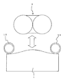
도 8은 본 발명의 실시의 형태 1에서의 전기청소기의 상방에서 본 바람의 흐름을 도시하는 개략도.
도 9는 본 발명의 실시의 형태 1에서의 사이클론식 먼지 분리부를 부착한 전기청소기 본체의 모식 단면(도 8의 A-A 단면)도.
도 10은 본 발명의 실시의 형태 1에서의 사이클론식 먼지 분리부를 떼어낸 전기청소기 본체의 모식 단면(도 8의 A-A 단면)도.
도 11은 본 발명의 실시의 형태 2에서의 핸들의 지지 상태를 도시하는 상면도 및 측면도.
도 12는 본 발명의 실시의 형태 2에서의 전기청소기를 운반할 때의 핸들의 상태를 도시하는 상면도 및 측면도.
도 13은 본 발명의 실시의 형태 2에서의 회동축받이부와 사이클론식 먼지 분리부의 볼록부와의 관계를 도시하는 주요부 단면도.BRIEF DESCRIPTION OF THE DRAWINGS The perspective view of the whole vacuum cleaner in
Fig. 2 is a perspective view of the vacuum cleaner main body of
3 is a perspective view illustrating a communication pipe in
Fig. 4 is a side cross-sectional view of the vacuum cleaner main body with a cyclone dust separator according to
Fig. 5 is a perspective view of the cyclone dust separator according to the first embodiment of the present invention removed from the vacuum cleaner main body.
Fig. 6 is a side view of the cyclone dust separator according to the first embodiment of the present invention, taken from the vacuum cleaner main body.
Fig. 7 is a schematic diagram showing the flow of wind seen from the side of the vacuum cleaner according to the first embodiment of the present invention.
Fig. 8 is a schematic diagram showing the flow of wind seen from above of the vacuum cleaner according to the first embodiment of the present invention.
FIG. 9 is a schematic cross-sectional view (AA cross section in FIG. 8) of the vacuum cleaner main body with a cyclone dust separator according to
The schematic cross section (AA cross section of FIG. 8) figure of the vacuum cleaner main body which removed the cyclone type dust separation part in
11 is a top view and a side view showing a support state of a handle in
12 is a top view and a side view showing a state of a handle when carrying the vacuum cleaner in
13 is an essential part cross sectional view showing a relationship between the pivotal bearing part and the convex part of the cyclone-type dust separator in
실시의 형태 1.
도 1은 본 발명의 실시의 형태 1에서의 전기청소기 전체의 사시도, 도 2는 본 발명의 실시의 형태 1에서의 전기청소기 본체의 사시도, 도 3은 본 발명의 실시의 형태 1에서의 연통 파이프를 도시하는 사시도, 도 4는 본 발명의 실시의 형태 1에서의 사이클론식 먼지 분리부를 부착한 전기청소기 본체의 측방 단면도, 도 5는 본 발명의 실시의 형태 1에서의 사이클론식 먼지 분리부를 전기청소기 본체로부터 떼어낸 사시도, 도 6은 본 발명의 실시의 형태 1에서의 사이클론식 먼지 분리부를 전기청소기 본체로부터 떼어낸 측면도, 도 7은 본 발명의 실시의 형태 1에서의 전기청소기의 측방에서 본 바람의 흐름을 도시하는 개략도, 도 8은 본 발명의 실시의 형태 1에서의 전기청소기의 상방에서 본 바람의 흐름을 도시하는 개략도, 도 9는 본 발명의 실시의 형태 1에서의 사이클론식 먼지 분리부를 부착한 전기청소기 본체의 모식 단면(도 8의 A-A 단면)도, 도 10은 본 발명의 실시의 형태 1에서의 사이클론식 먼지 분리부를 떼어낸 전기청소기 본체의 모식 단면(도 8의 A-A 단면)도이다.1 is a perspective view of an entire vacuum cleaner in
또한, 각각의 도면에서, 같은 부분 또는 상당한 부분에는 같은 부호를 붙이고, 일부의 설명을 생략한다.In addition, in each figure, the same code | symbol is attached | subjected to the same part or substantial part, and description of a part is abbreviate | omitted.
도 1부터 도 6에 의해, 본 발명의 실시의 형태 1에서의 전기청소기의 구성을 설명한다.1 to 6, the configuration of the vacuum cleaner according to the first embodiment of the present invention will be described.
도 1에 도시하는 바와 같이, 전기청소기(100)는 본체(1)와 사이클론식 먼지 분리부(2)와 호스 조립체(3)로 구성되어 있다. 호스 조립체(3)에는 일단에 호스 조립체 삽입부(4)가 마련되어 있고, 가요성을 갖는 예를 들면 벨로스와 같은 호스(5)가 접속되고, 또한, 호스(5)에는 본체(1)를 끌고 다니기 위한 파지부(6)가 접속되고, 연장 파이프(7)을 통하여 호스 조립체(3)의 타단에 먼지를 흡인하기 위한 흡입기구(8)가 접속되어 있다.As shown in FIG. 1, the
사이클론식 먼지 분리부(2)는 본체(1)에 노출한 상태에서 부착되고, 도 2에 도시하는 바와 같이 선회실(9)과 집진실(10)로 구성되어 있고, 선회실(9)의 부근에 흡인구(吸引口)(11)가 마련되어 있다. 사이클론식 먼지 분리부(2)는, 먼지의 움직임이나 수집 상황을 사용자에게 시인(視認)시키기 쉽게 한다는 배려 때문에 투명한 수지재로 형성되고, 명한 수지재는 대충격강도(對衝擊强度)가 그다지 강하지 않다는 것이 일반적이다.The cyclone
본체(1)에는, 본체(1)를 끌고 다닐 때의 진행 방향의 앞측에서, 좌우 방향의 중앙이 되도록 호스 조립체(3)를 접속하기 위한 호스 조립체 삽입구(12)가 마련되어 있고, 호스 조립체(3)를, 호스 조립체 삽입부(7)을 통하여 본체(1)에 접속하도록 되어 있다.The
또한, 본체(1)에는, 사이클론식 먼지 분리부(2)를 끼우도록 일측에 연통 파이프(13)와 타측에 배기부(14)가 거의 본체(1)의 측면이 되는 위치에 배설되어 있다. 연통 파이프(13)는 호스 조립체 삽입구(12)와 흡인구(11)를 연통하도록 배치되어 있고, 도 3에 도시하는 바와 같이, 호스 조립체 연통구(13a), 굴곡부(13b), 도통부(3c), 흡인구 접속부(13d)의 4점의 부품에 의해 구성되어 있다.Moreover, the
호스 조립체 연통구(13a), 굴곡부(13b), 도통부(3c), 흡인구 접속부(13d)는, 경질의 수지재, 예를 들면 ABS나 PP 등으로 형성되지만, 이들로 한정되는 것이 아니고, 의장성이나 대충격성, 가공성이나 비용을 고려하여 경질의 수지재, 금속재의 중에서 적절히 선택 가능하고, 이종재(異種材)의 조합에 의해 구성되어도 좋다.Although the hose assembly communication port 13a, the bent part 13b, the conduction part 3c, and the suction port connection part 13d are formed of a hard resin material, for example, ABS, PP, etc., it is not limited to these, In consideration of designability, high impact, workability and cost, it can be appropriately selected from hard resin materials and metal materials, and may be constituted by a combination of dissimilar materials.
연통 파이프(13)를 구성하는 4점의 부품 중, 호스 조립체 연통구(13a)는 본체 내에 수용된 상태에서 호스 조립체 삽입구(12)와 연통하고, 패킹(도시 생략)을 통하여 호스 조립체(3)와 연통하고 있다. 다른 3부품, 굴곡부(13b), 도통부(3c), 흡인구 접속부(13d)는 본체 외에 노출하도록 배설되어 있고, 흡인구 접속부(13d)가 흡인구(11)와 연통하고 있다.Of the four parts constituting the communication pipe 13, the hose assembly communication port 13a communicates with the hose assembly insertion hole 12 in a state accommodated in the main body, and communicates with the
연통 파이프(13)는, 본 실시의 형태 1에서는 4점의 부품으로 구성하였지만 이것으로 한정되는 것이 아니고, 4점 이외의 복수의 부품 점수나, 수지재를 블로우 성형에 의해 일체로 형성한 1점의 부품, 금속재를 굽힘가공 등에 의해 일체로 형성한 1점의 부품으로의 구성이라도 좋고, 의장성이나 대충격성, 가공성이나 비용에 의해 적절히 선택 가능하다.Although the communication pipe 13 was comprised from four points in this
배기부(14)에는, 복수의 배기구(14a 내지 14h)가 마련되어 있고(도 8 참조), 도 4에 도시하는 전동 송풍기(15)가 발생시키는 부압에 의해 생긴 공기류를 본체(1) 밖으로 배출할 수 있다.The
배기부(14)는, 본체(1)의 중심에 대해 연통 파이프(13)와 개략 대칭으로 배설되어 있기 때문에, 연통 파이프(13)와 같은 재질의 경질재로 형성되는 것이 의장적으로 바람직하지만, 이것으로 한정되는 것이 아니고, 의장성이나 대충격성, 가공성이나 비용에 의해 경질의 수지재, 금속재의 중에서 적절히 선택 가능하고, 연통 파이프(13)와 다른 경질재에 의해 형성되어도 좋고, 또한, 본체(1)와 일체적으로 형성되어도 좋다.Since the
사이클론식 먼지 분리부(2)는 도 5, 도 6에 도시하는 바와 같이 본체(1)와 착탈 가능하게 되어 있고, 사이클론식 먼지 분리부(2)를 본체(1)에 부착한 상태일 때, 사이클론식 먼지 분리부(2)에 마련된 공기류 배출부(16)와, 본체(1)에 마련된 공기류 도입부(17)로 연통하도록 되어 있다.When the cyclone
또한, 도 6에 도시하는 바와 같이 본체(1)의 측면 가까이에는 차륜(18)과, 본체(1)의 저면에는 캐스터(19)가 마련되어 있고 본체(1)를 끌고 다닐 때에 쓰인다.In addition, as shown in FIG. 6, the
다음에, 도 1과 도 2와 도 7과 도 8에 의해, 본 발명의 실시의 형태 1에서의 전기청소기의 동작을 설명한다.Next, the operation | movement of the vacuum cleaner in
파지부(6)에 있는 조작부(도시 생략)에서 전원을 넣으면 전동 송풍기(15)가 회전하여 부압이 발생하고, 이 부압에 의해 흡입기구(8)에서 먼지를 포함하는 공기를 흡입하게 된다. 흡입기구(8)에서 흡입된 먼지를 포함한 공기는, 연장 파이프(7), 파지부(6), 호스(5), 호스 조립체 삽입부(4)와 호스 조립체(3)를 경유하여 호스 조립체 삽입구(12)를 통하여 연통 파이프(13)에 유도된다.When power is supplied from an operation unit (not shown) in the
먼지를 흡입하는 동작, 즉 청소 작업을 하고 있을 때는, 파지부(6)를 쥐고서 흡입기구(8)를 조종하면서 호스 조립체(3)에 접속되어 있는 본체(1)를 끌고 다니도록 하여 광범위하게 이동시키게 되는데, 그 과정에서 가구나 벽에 충돌하는 일이 있고, 전술한 바와 같이, 대충격강도가 그다지 강하지 않은 투명한 수지재로 형성되는 것이 일반적이고 노출하고 있는 사이클론식 먼지 분리부(2)는, 도 9, 도 10에 도시하는 바와 같이 경질재로 형성된 연통 파이프(13)와 배기부(14)에 좌우를 보호받는 형태로 배설되어 있어서, 직접적인 충격을 받는 일이 없도록 배려되어 있다.When the dust suction operation, i.e., the cleaning operation, is carried out by holding the
또한, 사이클론식 먼지 분리부(2)를 보호한 형태로, 거의 본체(1)의 측면이 되는 위치에 배설되고, 가구나 벽에 충돌할 가능성이 있는 연통 파이프(13)와 배기부(14)도 경질재로 형성되어 있기 때문에, 충돌에 의한 충격을 받아도 파손의 가능성을 저감하도록 배려되어 있다Moreover, the communication pipe 13 and the
그리고, 호스 조립체(3)를 구성하는 가요성을 갖는 호스(5)가 개재하는 형태로 본체(1)는 끌려다니게 되는데, 호스 조립체(3)는, 좌우 방향의 중앙이 되도록 호스 조립체 삽입구(12)에 접속되어 있고, 끌고 다니기의 밸런스가 확보되어 있기 때문에, 사용자가 끌고 다님을 용이하게 할 수 있도록 배려되어 있다.And the
연통 파이프(13)에 유도된 먼지를 포함한 공기는 흡인구(11)를 통과하고, 사이클론식 먼지 분리부(2)의 선회실(9)로 유도되고, 선회실(9)에서 먼지를 포함한 공기를 선회시킴으로써, 관성력에 의해 먼지를 공기로부터 분리한다.The air containing the dust guided to the communication pipe 13 passes through the suction port 11, is led to the swinging chamber 9 of the cyclone
분리된 먼지는, 경사하여 배설되어 있는 사이클론식 먼지 분리부(2)의 아래쪽측의 집진실(10)에 수집되고, 분리된 공기는 공기류 배출부(16)로부터 공기류 도입부(17)를 통과하고, 전동 송풍기(15)를 경유하여 배기부(14)에 유도되고, 배기구(14a 내지 14h)로부터 본체(1) 밖으로 배출된다.The separated dust is collected in the
이상의 구성, 동작에 의해, 사이클론식 먼지 분리부를 구비한 전기청소기에서, 본체의 호스 조립체로의 추종성이 좋고, 진행 방향으로 용이하게 끌고 다닐 수 있다라는 효과를 이룰 수 있다.According to the above structure and operation | movement, in the vacuum cleaner provided with a cyclone type dust separation part, the followability of the main body to the hose assembly is good, and it can achieve the effect that it can be dragged easily in a travel direction.
또한, 끌고 다닐 때에 가구나 벽등에 충돌할 가능성이 있는 연통 파이프와 배기부를 경질재로 형성하였기 때문에, 파손의 가능성을 저감하고 안전성, 보전성을 향상시킨다는 효과를 이룰 수 있다.In addition, since the communication pipe and the exhaust portion, which are likely to collide with furniture or walls when being dragged, are formed of a hard material, the effect of reducing the possibility of breakage and improving safety and integrity can be achieved.
또한, 사이클론식 먼지 분리부를 청소 작업시의 충격으로부터 확실하게 보호하여 안전성, 보전성을 향상시킨다는 효과를 이룰 수 있다.In addition, the cyclone dust separator can be reliably protected from the impact during the cleaning operation, thereby achieving an effect of improving safety and integrity.
실시의 형태 2.Embodiment 2:
도 11은 본 발명의 실시의 형태 2에서의 핸들의 지지 상태를 도시하는 상면도 및 측면도, 도 12는 본 발명의 실시의 형태 2에서의 전기청소기를 운반할 때의 핸들의 상태를 도시하는 상면도 및 측면도, 도 13은 본 발명의 실시의 형태 2에서의 회동축받이부와 사이클론식 먼지 분리부의 볼록부와의 관계를 도시하는 주요부 단면도이다.11 is a top view and a side view showing a support state of a handle in
또한, 각각의 도면에서, 같은 부분 또는 상당하는 부분에는 같은 부호를 붙이고, 일부의 설명을 생략한다.In addition, in each figure, the same code | symbol is attached | subjected to the same part or corresponding part, and the description of a part is abbreviate | omitted.
도 11부터 도 13에 의해 본 발명의 실시의 형태 2에서의 전기청소기의 구성을 설명한다.The structure of the vacuum cleaner in
도 11부터 도 13에 도시하는 바와 같이, 연통 파이프(13)와 배기부(14)의 상방에 회동축받이부(21)가 마련되어 있고, 핸들(20)의 양단부에서 사이클론식 먼지 분리부(2)측을 향하여 내측에 마련된 회동축(22)을, 외측부터 삽입함으로써, 사이클론식 먼지 분리부(2)를 타고넘어서 회동 가능하게 연결되어 있다. 사이클론식 먼지 분리부(2)의 측방에는 볼록부(23)가, 회동축받이부(21)에 근접하고, 회동축받이부(21)의 가장 상기 사이클론식 먼지 분리부(2) 가까이 되는 부분보다도, 본체(1)의 측면측으로 돌출시켜서 마련되어 있기 때문에, 사이클론식 먼지 분리부(2)를 본체(1)에 부착할 때에, 사이클론식 먼지 분리부(2)의 볼록부(23)와 회동축받이부(21)가 부착 가이드가 되어, 위치가 특정하기 쉽게 된다.As shown in FIG. 11 thru | or 13, the
또한, 본 실시의 형태 2에서는 회동축받이부(21)의 일단측에, 사이클론식 먼지 분리부(2)의 볼록부(23)를 마련하도록 하였지만, 타단측에 마련하여도 좋고, 나아가서는 양단측에 마련하여도 부착 위치가 특정하기 쉬움은 마찬가지이다.In addition, although the convex part 23 of the cyclone type
다음에 도 11부터 도 13에 의해 본 발명의 실시의 형태 2에서의 전기청소기의 동작을 설명한다. 핸들(20)은, 본체(1)를 운반하지 않을 때에는 도 10에 도시하는 바와 같이 본체(1)의 후면측에 쓰러진 위치에서 지지되고, 본체(1)를 운반할 때에는 도 11에 도시하는 바와 같이 거의 수직 위치까지 회동시킬 수 있고, 본체(1)를 운반하기 용이하게 된다.Next, the operation | movement of the vacuum cleaner in
그리고, 사이클론식 먼지 분리부(2)를 때어내도, 핸들(20)은, 본체(1)측에 연결되어 있기 때문에, 본체(1)의 운반하에 지장은 없다.And since the
또한, 핸들(20)은 본 실시의 형태 2에서는, 회동 가능하게 하였지만, 이것으로 한정되는 것이 아니고, 고정식이라도 좋다.In addition, although the
이상의 구성, 동작에 의해, 사이클론식 먼지 분리부를 구비한 전기청소기로, 운반할 때에 사이클론식 먼지 분리부에 부담이 걸리지 않아, 본체가 낙하할 위험성이 적은 본체가 운반을 할 수 있다는 효과를 이룰 수 있다.According to the above configuration and operation, the vacuum cleaner equipped with the cyclone dust separator is not burdened with the cyclone dust separator at the time of transport, so that the main body with less risk of falling of the main body can be carried. have.
또한, 사이클론식 먼지 분리부가 벗겨져 있는 상태에서도 본체를 운반함이 용이하게 할 수 있다는 효과를 이룰 수 있다.In addition, it is possible to achieve the effect that it is easy to transport the body even in a state where the cyclone dust separator is peeled off.
또한, 사이클론식 먼지 분리부의 마련이 이해하기 쉽고 용이하게 할 수 있다는 효과를 이룰 수 있다.In addition, it is possible to achieve the effect that the provision of the cyclone dust separator is easy to understand and facilitate.
[산업상의 이용 가능성][Industrial Availability]
이상의 내용에 의해, 본 발명의 전기청소기는, 선회시켜서 관성력에 의해 먼지를 공기로부터 분리하는 사이클론식 먼지 분리부를 구비한 전기청소기에 널리 응용 가능하다.According to the above, the vacuum cleaner of this invention is widely applicable to the vacuum cleaner provided with the cyclone type dust separation part which turns and isolates dust from air by inertial force.
1 : 본체
2 : 사이클론식 먼지 분리부
3 : 호스 조립체
4 : 호스 조립체 삽입부
5 : 호스
6 : 파지부
7 : 연장 파이프
8 : 흡입기구
9 : 선회실
10 : 집진실
11 : 흡인구
12 : 호스 조립체 삽입구
13 : 연통 파이프
13a : 호스 조립체 연통구
13b : 굴곡부
13c : 도통부
13d : 흡인구 접속부
14 : 배기부
15 : 전동 송풍기
16 : 공기류 배출부
17 : 공기류 도입부
18 : 차륜
19 : 캐스터
20 : 핸들
21 : 회동축받이부
22 : 회동축
23 : 볼록부1: main body
2: cyclone dust separator
3: hose assembly
4: Hose assembly insert
5: hose
6: gripper
7: extension pipe
8: suction device
9: turning room
10: dust collection room
11: suction port
12: hose assembly insertion hole
13: communication pipe
13a: hose assembly communication port
13b: bend
13c: conduction part
13d: suction port connection
14: exhaust
15: electric blower
16: air flow outlet
17: air flow introduction
18: wheel
19: caster
20: handle
21: pivot bearing part
22: rotating shaft
23: convex
Claims (9)
본체 내에 배설된 전동 송풍기와,
일단에 흡입기구가 마련되고 가요성을 갖는 호스가 마련된 호스 조립체와,
상기 본체에 마련된 상기 호스 조립체를 접속하는 호스 조립체 삽입구와,
상기 본체에 착탈 자유롭게 배설되고, 상기 전동 송풍기가 발생시키는 부압에 의해 먼지를 포함한 공기를 흡인하는 흡인구와 먼지를 포함한 공기를 선회시키는 선회실과 먼지를 수집하는 집진실이 마련되고, 관성력에 의해 먼지를 공기로부터 분리하는 사이클론식 먼지 분리부를 구비하고,
상기 흡인구는, 연통 파이프에 의해 상기 호스 조립체 삽입구와 연통되어 있는 것을 특징으로 하는 전기청소기.In the vacuum cleaner which turns and separates dust from air by inertia,
With the electric blower installed in the body,
A hose assembly provided with a suction mechanism at one end and having a flexible hose,
A hose assembly insertion hole for connecting the hose assembly provided in the main body;
The main body is detachably attached to the main body, provided with a suction port for sucking air containing dust by a negative pressure generated by the electric blower, a turning room for turning air containing dust, and a dust collecting chamber for collecting dust. It is provided with a cyclone dust separator for separating from the air,
The suction port is in communication with the hose assembly insertion port by a communication pipe, characterized in that the vacuum cleaner.
상기 호스 조립체 삽입구는, 상기 본체 끌고 다니는 진행 방향 앞측의 개략 중앙에 배설되어 있는 것을 특징으로 하는 전기청소기.The method of claim 1,
The hose assembly insertion port is disposed at an outline center in the front of the main body in the traveling direction.
상기 연통 파이프는, 상기 본체 측면의 일측에 배설되고, 타측에 배기부를 구비한 것을 특징으로 하는 전기청소기.The method of claim 1,
The communication pipe is disposed on one side of the side surface of the main body, the other side is provided with an exhaust unit, characterized in that the vacuum cleaner.
상기 연통 파이프, 또는 상기 배기부의 어느 한쪽, 또는 그 양쪽이, 상기 본체의 상기 사이클론식 먼지 분리부를 배설하는 면보다도, 상방으로 돌출하고 있는 것을 특징으로 하는 전기청소기.The method of claim 3, wherein
Either one or both of said communication pipe or the said exhaust part protrudes upward rather than the surface which arrange | positions the said cyclone type dust separation part of the said main body, The electric vacuum cleaner characterized by the above-mentioned.
상기 연통 파이프는, 경질의 수지재, 또는 금속재의 어느 하나로 형성되어 있는 것을 특징으로 하는 전기청소기.The method according to any one of claims 1, 3 or 4,
The communication pipe is formed of either a hard resin material or a metal material.
상기 연통 파이프는, 복수의 부품으로 구성되어 있는 것을 특징으로 하는 전기청소기.The method according to any one of claims 1, 3 or 4,
The communication pipe is composed of a plurality of parts, characterized in that the vacuum cleaner.
상기 본체에, 운반용의 핸들을 구비한 것을 특징으로 하는 전기청소기.The method according to any one of claims 1 to 4,
An electric vacuum cleaner, wherein said main body is provided with a handle for carrying.
상기 본체의 상기 사이클론식 먼지 분리부를 배설하는 면에, 상기 사이클론식 먼지 분리부보다 외측에 배설된 회동축받이부를 구비하고,
상기 핸들은 상기 회동축받이부에 회동 자유롭게 축지되고, 운반할 때에는 거의 수직 위치까지 회동하고, 운반하지 않을 때에는 상기 본체 후면측으로 쓰러져서, 상기 사이클론식 먼지 분리부의 외주에서 지지되는 것을 특징으로 하는 전기청소기.8. The method of claim 7,
A rotation shaft receiving portion disposed on the outer side of the cyclone dust separation unit on a surface of the main body in which the cyclone dust separation unit is disposed;
And the handle is freely rotatably pivoted to the pivot shaft portion, rotates to a substantially vertical position when transported, and falls to the rear side of the main body when not transported, and is supported on the outer periphery of the cyclone dust separator.
상기 사이클론식 먼지 분리부에, 상기 회동축받이부의 가장 상기 사이클론식 먼지 분리부 가까이 되는 부분보다도 상기 본체 측면측으로 돌출시킨 볼록부를 구비한 것을 특징으로 하는 전기청소기.The method of claim 8,
And said convex portion which protrudes toward the side surface of said main body, rather than a portion that is closest to said cyclone-type dust separator, said cyclone-type dust separator.
Applications Claiming Priority (2)
| Application Number | Priority Date | Filing Date | Title |
|---|---|---|---|
| JP2010024194 | 2010-02-05 | ||
| JPJP-P-2010-024194 | 2010-02-05 |
Publications (1)
| Publication Number | Publication Date |
|---|---|
| KR20120102767A true KR20120102767A (en) | 2012-09-18 |
Family
ID=44355165
Family Applications (1)
| Application Number | Title | Priority Date | Filing Date |
|---|---|---|---|
| KR1020127017898A Ceased KR20120102767A (en) | 2010-02-05 | 2010-12-20 | Electric cleaner |
Country Status (5)
| Country | Link |
|---|---|
| JP (1) | JP5477392B2 (en) |
| KR (1) | KR20120102767A (en) |
| CN (1) | CN102724904B (en) |
| TW (1) | TWI448269B (en) |
| WO (1) | WO2011096143A1 (en) |
Cited By (1)
| Publication number | Priority date | Publication date | Assignee | Title |
|---|---|---|---|---|
| CN104665705B (en) * | 2013-11-29 | 2017-09-12 | 莱克电气股份有限公司 | Dust cup of dust collector and dust catcher with modified cyclone |
Families Citing this family (8)
| Publication number | Priority date | Publication date | Assignee | Title |
|---|---|---|---|---|
| GB2503252B (en) * | 2012-06-20 | 2014-12-17 | Dyson Technology Ltd | A self righting cleaning appliance |
| GB2503253B (en) | 2012-06-20 | 2014-10-15 | Dyson Technology Ltd | A cleaning appliance |
| GB2503251C (en) | 2012-06-20 | 2015-07-15 | Dyson Technology Ltd | A self righting cleaning appliance |
| GB2503255B (en) | 2012-06-20 | 2014-10-15 | Dyson Technology Ltd | A cleaning appliance |
| GB2503254B (en) | 2012-06-20 | 2014-12-17 | Dyson Technology Ltd | A cleaning appliance |
| GB2503671B (en) | 2012-07-03 | 2014-12-17 | Dyson Technology Ltd | Control of a brushless motor |
| GB2503670B (en) | 2012-07-03 | 2014-12-10 | Dyson Technology Ltd | Method of preheating a brushless motor |
| JP7085425B2 (en) * | 2018-07-04 | 2022-06-16 | シャープ株式会社 | Vacuum cleaner |
Family Cites Families (6)
| Publication number | Priority date | Publication date | Assignee | Title |
|---|---|---|---|---|
| JP2003180570A (en) * | 2001-12-21 | 2003-07-02 | Sanyo Electric Co Ltd | Vacuum cleaner |
| GB0203147D0 (en) * | 2002-02-11 | 2002-03-27 | Dyson Ltd | An exhaust assembly |
| CN1299625C (en) * | 2002-09-25 | 2007-02-14 | 东芝泰格有限公司 | Electric vacuum cleaner |
| JP2004236932A (en) * | 2003-02-07 | 2004-08-26 | Hitachi Home & Life Solutions Inc | Electric vacuum cleaner |
| GB2413943B (en) * | 2004-05-13 | 2007-06-27 | Dyson Ltd | Cleaning appliance |
| JP5010345B2 (en) * | 2007-05-21 | 2012-08-29 | 株式会社東芝 | Electric vacuum cleaner |
-
2010
- 2010-12-20 KR KR1020127017898A patent/KR20120102767A/en not_active Ceased
- 2010-12-20 JP JP2011552669A patent/JP5477392B2/en not_active Expired - Fee Related
- 2010-12-20 CN CN201080062398.1A patent/CN102724904B/en not_active Expired - Fee Related
- 2010-12-20 WO PCT/JP2010/072914 patent/WO2011096143A1/en not_active Ceased
-
2011
- 2011-01-18 TW TW100101730A patent/TWI448269B/en not_active IP Right Cessation
Cited By (1)
| Publication number | Priority date | Publication date | Assignee | Title |
|---|---|---|---|---|
| CN104665705B (en) * | 2013-11-29 | 2017-09-12 | 莱克电气股份有限公司 | Dust cup of dust collector and dust catcher with modified cyclone |
Also Published As
| Publication number | Publication date |
|---|---|
| CN102724904B (en) | 2015-01-21 |
| TWI448269B (en) | 2014-08-11 |
| TW201200094A (en) | 2012-01-01 |
| JP5477392B2 (en) | 2014-04-23 |
| JPWO2011096143A1 (en) | 2013-06-10 |
| WO2011096143A1 (en) | 2011-08-11 |
| CN102724904A (en) | 2012-10-10 |
Similar Documents
| Publication | Publication Date | Title |
|---|---|---|
| KR20120102767A (en) | Electric cleaner | |
| US20140020203A1 (en) | Vacuum Cleaner | |
| US7749294B2 (en) | Compact robot vacuum cleaner | |
| KR101924350B1 (en) | Vacuum cleaner having cyclone dust collecting apparatus | |
| CN101248972A (en) | electric vacuum cleaner | |
| JP3981661B2 (en) | Dust cup attaching / detaching device for cyclone vacuum cleaner and cyclone vacuum cleaner provided with the same | |
| KR20060119587A (en) | Vacuum cleaner | |
| CN109567664A (en) | Electric dust collector | |
| CN102293609B (en) | Upright Vacuum Cleaner | |
| JP2016010499A (en) | Vacuum cleaner | |
| JP5565092B2 (en) | Electric vacuum cleaner | |
| JP5935708B2 (en) | Electric vacuum cleaner | |
| CN104095584B (en) | Dust catcher | |
| JP6288112B2 (en) | Vacuum cleaner suction tool and vacuum cleaner equipped with the suction tool | |
| JP2009072627A5 (en) | ||
| KR102095103B1 (en) | Vacuum cleaner | |
| EP2677913B1 (en) | Vacuum cleaner | |
| JP6358136B2 (en) | Electric vacuum cleaner | |
| JP6051010B2 (en) | Electric vacuum cleaner | |
| JP4354476B2 (en) | Electric vacuum cleaner | |
| JP2006296984A (en) | Electric vacuum cleaner | |
| JP6051007B2 (en) | Electric vacuum cleaner | |
| KR20070092495A (en) | Cleaner robot | |
| KR100628056B1 (en) | Vacuum cleaner | |
| JP6879793B2 (en) | Electric vacuum |
Legal Events
| Date | Code | Title | Description |
|---|---|---|---|
| A201 | Request for examination | ||
| PA0105 | International application |
Patent event date: 20120710 Patent event code: PA01051R01D Comment text: International Patent Application |
|
| PA0201 | Request for examination | ||
| PG1501 | Laying open of application | ||
| E902 | Notification of reason for refusal | ||
| PE0902 | Notice of grounds for rejection |
Comment text: Notification of reason for refusal Patent event date: 20130827 Patent event code: PE09021S01D |
|
| E601 | Decision to refuse application | ||
| PE0601 | Decision on rejection of patent |
Patent event date: 20140226 Comment text: Decision to Refuse Application Patent event code: PE06012S01D Patent event date: 20130827 Comment text: Notification of reason for refusal Patent event code: PE06011S01I |