KR20110115716A - Light-emitting device with phosphor of strontium oxyosilicate type - Google Patents
Light-emitting device with phosphor of strontium oxyosilicate type Download PDFInfo
- Publication number
- KR20110115716A KR20110115716A KR1020100035190A KR20100035190A KR20110115716A KR 20110115716 A KR20110115716 A KR 20110115716A KR 1020100035190 A KR1020100035190 A KR 1020100035190A KR 20100035190 A KR20100035190 A KR 20100035190A KR 20110115716 A KR20110115716 A KR 20110115716A
- Authority
- KR
- South Korea
- Prior art keywords
- light emitting
- light
- phosphor
- emitting diode
- emitting device
- Prior art date
- Legal status (The legal status is an assumption and is not a legal conclusion. Google has not performed a legal analysis and makes no representation as to the accuracy of the status listed.)
- Granted
Links
Images


Classifications
-
- H—ELECTRICITY
- H10—SEMICONDUCTOR DEVICES; ELECTRIC SOLID-STATE DEVICES NOT OTHERWISE PROVIDED FOR
- H10H—INORGANIC LIGHT-EMITTING SEMICONDUCTOR DEVICES HAVING POTENTIAL BARRIERS
- H10H20/00—Individual inorganic light-emitting semiconductor devices having potential barriers, e.g. light-emitting diodes [LED]
- H10H20/80—Constructional details
- H10H20/85—Packages
- H10H20/851—Wavelength conversion means
- H10H20/8511—Wavelength conversion means characterised by their material, e.g. binder
- H10H20/8512—Wavelength conversion materials
-
- H—ELECTRICITY
- H10—SEMICONDUCTOR DEVICES; ELECTRIC SOLID-STATE DEVICES NOT OTHERWISE PROVIDED FOR
- H10H—INORGANIC LIGHT-EMITTING SEMICONDUCTOR DEVICES HAVING POTENTIAL BARRIERS
- H10H20/00—Individual inorganic light-emitting semiconductor devices having potential barriers, e.g. light-emitting diodes [LED]
- H10H20/80—Constructional details
- H10H20/85—Packages
- H10H20/858—Means for heat extraction or cooling
-
- H—ELECTRICITY
- H10—SEMICONDUCTOR DEVICES; ELECTRIC SOLID-STATE DEVICES NOT OTHERWISE PROVIDED FOR
- H10W—GENERIC PACKAGES, INTERCONNECTIONS, CONNECTORS OR OTHER CONSTRUCTIONAL DETAILS OF DEVICES COVERED BY CLASS H10
- H10W72/00—Interconnections or connectors in packages
- H10W72/01—Manufacture or treatment
- H10W72/015—Manufacture or treatment of bond wires
- H10W72/01515—Forming coatings
-
- H—ELECTRICITY
- H10—SEMICONDUCTOR DEVICES; ELECTRIC SOLID-STATE DEVICES NOT OTHERWISE PROVIDED FOR
- H10W—GENERIC PACKAGES, INTERCONNECTIONS, CONNECTORS OR OTHER CONSTRUCTIONAL DETAILS OF DEVICES COVERED BY CLASS H10
- H10W72/00—Interconnections or connectors in packages
- H10W72/071—Connecting or disconnecting
- H10W72/075—Connecting or disconnecting of bond wires
-
- H—ELECTRICITY
- H10—SEMICONDUCTOR DEVICES; ELECTRIC SOLID-STATE DEVICES NOT OTHERWISE PROVIDED FOR
- H10W—GENERIC PACKAGES, INTERCONNECTIONS, CONNECTORS OR OTHER CONSTRUCTIONAL DETAILS OF DEVICES COVERED BY CLASS H10
- H10W90/00—Package configurations
- H10W90/701—Package configurations characterised by the relative positions of pads or connectors relative to package parts
- H10W90/751—Package configurations characterised by the relative positions of pads or connectors relative to package parts of bond wires
- H10W90/756—Package configurations characterised by the relative positions of pads or connectors relative to package parts of bond wires between a chip and a stacked lead frame, conducting package substrate or heat sink
Landscapes
- Luminescent Compositions (AREA)
Abstract
스트론튬 옥시오소실리케이트 유형의 형광체를 갖는 발광 장치가 개시된다. 이 발광 장치는 자외선 또는 가시광선 영역의 광을 발생시키는 발광 다이오드와 상기 발광 다이오드 주위에 배치되어 상기 발광 다이오드로부터 방출된 광의 적어도 일부를 흡수하여 흡수광과 다른 파장의 광을 방출하는 형광체를 포함한다. 이 형광체는 0 내지 0.05 사이의 값을 갖는 칼슘 몰분율 x가 일반식 Sr3 -x-y- zCaxMII ySiO5 : Euz 를 갖는 실리케이트 형광체로 첨가된 것을 특징으로 한다. 제한된 범위의 칼슘을 스트론튬 옥시오소실리케이트 모 형광체에 첨가함으로써 방사 부하에 대한 안정성 및 습도에 대한 내성을 향상시킬 수 있어 발광 장치의 수명을 증가시킬 수 있다.A light emitting device having phosphors of the strontium oxyosilicate type is disclosed. The light emitting device includes a light emitting diode for generating light in an ultraviolet or visible light region and a phosphor disposed around the light emitting diode to absorb at least a portion of the light emitted from the light emitting diode to emit light having a wavelength different from that of the absorbed light. . This phosphor is characterized in that a calcium mole fraction x having a value between 0 and 0.05 is added as a silicate phosphor having the general formula Sr 3 -xy- z Ca x M II y SiO 5 : Eu z . By adding a limited range of calcium to the strontium oxyosilicate mother phosphor, it is possible to improve stability to radiation loads and resistance to humidity, thereby increasing the lifespan of the light emitting device.
Description
본 발명은 더 높은 에너지 여기 방사, 즉, 예를 들어, UV 빔 또는 청색광을 바람직하게 가시 스펙트럼 범위에서 방출되는 긴 파장 방사로 높은 효율로 변환시킬 수 있는 실리케이트 화합물에 기반한 효율적 무기 형광체를 갖는 발광 장치에 관한 것이다.The present invention provides a light emitting device having an efficient inorganic phosphor based on a silicate compound capable of converting higher energy excitation radiation, ie, UV beams or blue light, preferably with long wavelength radiation emitted in the visible spectral range. It is about.
형광체는 색이 있는 또는 백색의 광을 방출하는 LED 형태의 광원에서 사용될 수 있고, 여기서 이러한 형광체는, 선택적으로 추가 발광체와 배합하여, LED로부터 발산하는 자외선 또는 청색 초기 방사를 긴 파장 2차 방사, 특히 백색 광으로 효과적으로 변환시키는데 사용된다.Phosphors can be used in light sources in the form of LEDs that emit colored or white light, where such phosphors, optionally in combination with additional light emitters, can be used for long wavelength secondary radiation, In particular, it is used to effectively convert to white light.
예를 들어, 세륨-도핑된 이트륨 알루미늄 가넷, Eu-활성 알칼리토금속 오소실리케이트 및 유사하게 도핑된 질화물의 다른 조성과 같은 높은 발광 출력을 갖는 다양한 형광체가 이러한 어플리케이션에 대하여 이미 개시되었지만, LED 어플리케이션을 위한 향상된 물질을 개발하기 위한 추가 노력들이 알려져 있다. 개발 동향은 특히 더 좋은 온도 특성을 갖고 생성된 방사 부하(radiation load) 및 대기 습도와 기타 환경적 요인의 영향에 더 높은 안정성을 갖는 형광체를 발견하는 것이다. 이러한 발광체는 상대적으로 높은 전력 소비 및 향상된 수명을 갖는 LED 램프 등의 발광 장치의 제조에 필요하다.For example, various phosphors with high luminous output, such as cerium-doped yttrium aluminum garnets, Eu-active alkaline earth metal orthosilicates, and other compositions of similarly doped nitrides, have already been disclosed for these applications, but for LED applications Further efforts are known to develop improved materials. The development trend is to find phosphors that have particularly better temperature characteristics and higher stability to the resulting radiation load and the influence of atmospheric humidity and other environmental factors. Such light emitters are required for the manufacture of light emitting devices such as LED lamps having relatively high power consumption and improved lifetime.
Sr3SiO5:Eu의 일반적 형태를 갖는 유로퓸-활성 알칼리토금속 옥시오소실리케이트는 색이 있는 또는 백색의 광을 방출하는 LED에서 사용되는 것이 알려져 있다. 이러한 형광체는 예를 들어 WO 2004/085570A1 및 WO 2006/081803A1 및 예를 들어, Park, Joung-Kyu, et al., in Appl., Phys. Lett. 84 (2004), 1647-49, 및 Jee, Soon-Duc, et al., in J. Mater. Sci. 41 (2006), 3139-41과 같은 다양한 과학적 공개물에 개시되어 있다.It is known that europium-activated alkaline earth metal oxyosilicates having the general form of Sr 3 SiO 5 : Eu are used in LEDs that emit colored or white light. Such phosphors are described, for example, in WO 2004 / 085570A1 and WO 2006 / 081803A1 and in, for example, Park, Joung-Kyu, et al., In Appl., Phys. Lett. 84 (2004), 1647-49, and Jee, Soon-Duc, et al., In J. Mater. Sci. 41 (2006), 3139-41.
공지된 발광체는 황색에서 오렌지색 범위의 가시 스펙트럼에서 방출하고, 최대 250℃ 온도까지 높은 발광 효율 및 극히 낮은 열적 퀀칭(quenching)에 의해 구별된다. 이 점에서, 그것들은 온백색 LED에 대한 형광체 혼합물 내의 오렌지색 성분으로서, 마찬가지로 580 내지 610nm 사이에서 방출하는 오소실리케이트들에 비해 상당히 우수하고, 그들의 이로운 성질 및 상당히 낮은 제조비용 때문에 이들 어플리케이션에 대해 점점 선호되는 적색 방출 질화물 형광체와 경쟁할 수 있다.Known emitters emit in the visible spectrum in the yellow to orange range and are distinguished by high luminous efficiency and extremely low thermal quenching up to temperatures of up to 250 ° C. In this respect, they are orange components in the phosphor mixture for warm white LEDs, which are likewise considerably superior to orthosilicates emitting between 580 and 610 nm and are increasingly preferred for these applications because of their beneficial properties and significantly lower manufacturing costs. It can compete with red emitting nitride phosphors.
한편, 특정 사용 조건하에서 이러한 형광체로부터 제조된 LED가 상대적으로 짧은 수명을 가질 수 있다는 것이 발견되었다. 이 해로운 거동(behaviour)의 가능한 원인은 유로퓸-도핑된 알칼리토금속 옥시오소실리케이트들의 상대적으로 높은 습도 민감성이라 추정된다. 이러한 불안정성의 결과로, 개시된 발광체의 산업적 사용가능성이 제한될 수 있거나 특정 영역에서는 적어도 크게 복잡할 수 있다.On the other hand, it has been found that LEDs made from such phosphors can have a relatively short life under certain conditions of use. A possible cause of this detrimental behavior is presumed to be the relatively high humidity sensitivity of europium-doped alkaline earth metal oxyosilicates. As a result of this instability, the industrial availability of the disclosed light emitters may be limited or at least greatly complicated in certain areas.
따라서, 본 발명의 목적은 향상된 특성, 특히 다양한 기술적 어플리케이션에서 사용하기 위한 효율적 방사 변환기로서 적합한, 대기 습도에 상당히 증가된 안정성을 갖는 새롭고 화학적으로 변형된 옥시오소실리케이트 형광체를 채택한 발광 장치를 제공하는 것이다.It is therefore an object of the present invention to provide a light emitting device employing new and chemically modified oxyosilicate phosphors with significantly increased stability to atmospheric humidity, which are suitable as improved radiation converters, particularly for use in various technical applications. .
본 발명의 실시예들에 따른 발광 장치는 자외선 또는 가시광선 영역의 광을 발생시키는 발광 다이오드와 상기 발광 다이오드 주위에 배치되어 상기 발광 다이오드로부터 방출된 광의 적어도 일부를 흡수하여 흡수광과 다른 파장의 광을 방출하는 형광체를 포함한다. 여기서, 상기 목적은 모(parent) 형광체 격자 Sr3SiO5 에서 화합물의 화학양론(stoichiometry) 및 이의 결정 구조를 변경시키지 않고 스트론튬(Sr)의 작은 양을 선택적으로 칼슘(Ca)으로 대체하는 수단의 사용에 의해 달성된다. 이러한 치환은 상응하는 유로퓸-활성 옥시오소실리케이트 발광체들의 대기 습도 및 기타 환경적 요인에 대한 안정성에서 상당한 증가 및, 그로부터 제조된 발광 다이오드(LED)의 수명에서 뚜렷한 향상을 야기한다.The light emitting device according to the embodiments of the present invention absorbs at least a portion of the light emitting diodes generating light in the ultraviolet or visible light region and the light emitted from the light emitting diodes disposed around the light emitting diodes so as to have light having a wavelength different from that of the absorbed light. It includes a phosphor that emits light. The object here is to provide a means for selectively replacing a small amount of strontium (Sr) with calcium (Ca) without altering the stoichiometry of the compound and its crystal structure in the parent phosphor lattice Sr 3 SiO 5 . Is achieved by use. This substitution results in a significant increase in stability to atmospheric humidity and other environmental factors of the corresponding europium-active oxyosilicate emitters and a marked improvement in the lifetime of the light emitting diodes (LEDs) produced therefrom.
칼슘 치환의 긍적적 효과는 선택된 좁은 칼슘 농도 범위에 제한된다. 만일 이것이 초과되면, 칼슘의 Sr3SiO5 매질(matrix)로의 연속되는 함유의 결과로서 바람직한 알칼리토금속 옥시오소실리케이트가 기본적인 형광체 합성물로 더 이상 형성되지 않고, 대신에 상당한 정도로 증가된 칼슘 농도를 가지고, 상응하는 오소실리케이트 조성물 (Sr,Ca)2SiO4이 사실상 형성되는 것이다.The positive effect of calcium substitution is limited to the narrow calcium concentration range chosen. If this is exceeded, preferred alkaline earth metal oxyosilicates, as a result of the continuous incorporation of calcium into the Sr 3 SiO 5 matrix, are no longer formed into the basic phosphor composite, but instead have a significantly increased calcium concentration, The corresponding orthosilicate composition (Sr, Ca) 2 SiO 4 is what is formed in nature.
WO 2006/081803A1에 개시되어 있는 일반식 (Sr1 -x- yCaxBay)3SiO5:Eu2의 혼합 실리케이트의 경우, x는 최대 0.3까지의 값으로 간주될 수 있는데, x-레이 구조 검사에 따르면, 바람직한 알칼리토금속 옥시오소실리케이트 형광체가 공지된 제조 조건하에서 x > 0.05의 칼슘 분율로는 더 이상 합성될 수 없으며, 대신에 알칼리토금속 오소실리케이트가 우세한(predominant) 양으로 형성된다.WO 3 SiO 5 general formula (Sr 1 -x- y Ca x Ba y) disclosed in 2006 / 081803A1: In the case of mixed silicates of Eu 2, x is may be considered to be a value up to 0.3, x- ray According to the structural inspection, preferred alkaline earth oxyosilicate phosphors can no longer be synthesized at a calcium fraction of x> 0.05 under known manufacturing conditions, and instead alkaline earth metal orthosilicate is formed in a predominant amount.
한편, Sr3SiO5 격자의 형성을 간섭(interfere)하지 않는 x < 0.05 의 칼슘의 적은 양의 함유는 상응하는 유로퓸-도핑된 발광체의 습도 내성의 상당한 개선 및 그로부터 제조된 LED의 수명에서 상당한 증가를 야기한다는 것이 놀랍게도 발견되었다.
On the other hand, the inclusion of small amounts of calcium of x <0.05 that does not interfere with the formation of the Sr 3 SiO 5 lattice is a significant improvement in the humidity resistance of the corresponding europium-doped emitters and a significant increase in the lifetime of the LEDs produced therefrom. It was surprisingly found to cause.
(스트론튬 옥시오소실리케이트 형광체 내에서의 수단)(Means in Strontium Oxyosilicate Phosphor)
생성된 방사 부하에 대한 향상된 안정성 및 대기 습도의 영향에 대한 내성을 갖는 본 발명에 따른 스트론륨 옥시오소실리케이트 형광체는 일반식 Sr3 -x-y-zCaxMII ySiO5 : Euz에 의해 표현될 수 있는 바, 칼슘 몰분율 x를 0 내지 0.05 사이 값으로 할 수 있고, 한편, 유로퓸 몰분율 z에 대하여 ≤ 0.25의 범위의 값이 전형적이다. 최고 활성체(activator) 농도는 형광체의 특정 사용 조건에 따라 다르고 실험적으로 용이하게 결정될 수 있다.The strontium oxyosilicate phosphors according to the invention with improved stability to the resulting radiation load and resistance to the effects of atmospheric humidity can be represented by the general formula Sr 3 -xyz Ca x M II y SiO 5 : Eu z As can be seen, the calcium mole fraction x can be a value between 0 and 0.05, while a value in the range of <0.25 is typical for the europium mole fraction z. The highest activator concentration depends on the specific conditions of use of the phosphor and can be easily determined experimentally.
상기 일반식에서, MII 는 마그네슘(mg), 바륨(Ba), 구리(Cu), 아연(Zn) 및 망간(Mn) 원소로 이루어진 군에서 선택된 2가 금속 이온들을 나타내고, 이들 이온들은 선택적으로 모 형광체 격자내로 추가적으로 함유될 수 있다. 바륨의 경우에는, 스트론튬에 대한 완전한 대체가 가능하고; 스트론튬에 부가하여 함유되는 다른 2가 금속 이온들의 분율은 y = 0.5까지 일 수 있다.In the general formula, M II represents divalent metal ions selected from the group consisting of magnesium (mg), barium (Ba), copper (Cu), zinc (Zn) and manganese (Mn) elements, and these ions are selectively It may be further contained into the phosphor lattice. In the case of barium, a complete replacement for strontium is possible; The fraction of other divalent metal ions contained in addition to strontium can be up to y = 0.5.
유로퓸(Eu)과 별도로 그리고 이 도핑 원소에 선택적 추가적으로, 원리적으로 예를 들어, 사마륨(Sm) 또는 이테르븀(Yb)과 같은 2가 희토류 이온, 또는 예를 들어 세륨 이온(Ce3 +)과 같은 특정 3가 희토류 이온이 또한 활성체(activator)로서 적합하다.Europium (Eu) and additionally and optionally additionally, as principle, for example, samarium (Sm), or ytterbium (Yb) 2 has a rare-earth ion, or for example, cerium ions, such as (Ce 3 +) in the doping element Certain trivalent rare earth ions are also suitable as activators.
발광 성질 및 안정성 거동을 최적화하는 목적으로, 이러한 형광체는 또한 그들의 조성물에서 추가 변형을 겪는다. 따라서, 예를 들어, 실리콘(Si)은 게르마늄(Ge)에 의해 및/또는, 알루미늄(Al), 갈륨(Ga), 붕소(B) 또는 인(P)에 의해 대체될 수 있으나, 마지막으로 언급된 경우에서는 필요한 경우 취해질 수 있는 전하 균형(charge balance)을 유지하기 위한 적절한 조치를 필요하다면 취해야 한다. 이것은 또한 예를 들어, 리튬(Li), 나트륨(Na) 및 칼륨(K)과 같은 1가 양이온 또는, 플루오린(F), 염소(Cl), 브롬(Br) 또는 요오드(I)와 같은 음이온을 모 격자 내로 추가로 함유시키는 것으로 이루어질 수 있다.
For the purpose of optimizing luminescent properties and stability behavior, these phosphors also undergo further modifications in their compositions. Thus, for example, silicon (Si) may be replaced by germanium (Ge) and / or by aluminum (Al), gallium (Ga), boron (B) or phosphorus (P), but last mentioned Where appropriate, appropriate measures should be taken if necessary to maintain a charge balance that can be taken if necessary. It is also for example monovalent cations such as lithium (Li), sodium (Na) and potassium (K) or anions such as fluorine (F), chlorine (Cl), bromine (Br) or iodine (I) May be further contained into the parent lattice.
바람직한 실시예에서, 생성된 방사 부하에 대한 향상된 안정성 및 대기 습도의 영향에 대한 내성을 갖는 형광체는 화학식 Sr3 -x-y- zCaxBaySiO5 : Euz 를 갖는데, 여기에서 본 발명에 따른 몰분율은 0 < x ≤ 0.05, 0 ≤ y ≤ 0.5, 및 z ≤ 0.25이다.In a preferred embodiment, the phosphor having improved stability to the resulting radiation load and resistance to the effects of atmospheric humidity has the formula Sr 3 -xy- z Ca x Ba y SiO 5 : Eu z , according to the invention The molar fractions are 0 <x <0.05, 0 <y <0.5, and z <0.25.
높은 에너지 방사로 여기하면, 형광체는 그들의 특정 화학적 조성에 따라 스펙트럼의 가시 부분, 바람직하게는 560 내지 620nm 사이의 범위 내에서 방출한다. Eu2+ 여기 발광은 220nm의 자외선에서 550nm의 가시 광선 범위이고, 이는 본 발명의 발광체가 녹색 여기 방사로도 여기되어 효율적인 황색 내지 오렌지색 또는 적색 발광을 발생할 수 있다는 것을 뜻한다. 또한, 강도가 높고 기술적으로 사용가능한 발광 과정은 본 발명에 따른 매우 낮은 Ca 분율을 갖는 형광체를 전자 빔, X-레이 빔 또는 감마 방사로 조사할 때도 발생한다.When excited with high energy radiation, the phosphors emit within the visible portion of the spectrum, preferably between 560 and 620 nm, depending on their specific chemical composition. Eu 2+ excitation light emission ranges from 220 nm ultraviolet light to 550 nm visible light, which means that the light emitter of the present invention can also be excited by green excitation radiation to produce efficient yellow to orange or red light emission. In addition, a high intensity and technically usable luminescence process also occurs when irradiating phosphors with very low Ca fractions according to the invention with electron beams, X-ray beams or gamma radiation.
향상된 발광 성질들 때문에, 본 발명에 따른 매우 낮은 Ca 분율을 갖는 형광체는 이온화 감마 레이, X-레이 또는 전자 빔, 자외선, 청색 또는 녹색 방사를 바람직하게 황색, 오렌지색 및 적색 스펙트럼 범위에서 방출되는 긴 파장 가시광선으로 변환시키는 방사 변환기로서 사용될 수 있다. 이것은 그것들이 다양한 기술 장치들, 예를 들어 음극선관 및 다른 영상 생성 시스템 (스캐닝 레이저 빔 시스템), X-레이 영상 변환기, 형광 램프, 및 색이 있는 및 백색의 광을 방출하는 LED, 태양전지 또는 온실 시트 및 유리에서 방사 변환체로서 다양하게 사용될 수 있으며, 단독 또는 다른 청색, 녹색, 황색 및/또는 적색 방출 형광체와 배합하여 사용될 수 있음을 의미한다.Because of the improved luminescence properties, the phosphors with very low Ca fractions according to the invention have long wavelengths which emit ionized gamma ray, X-ray or electron beam, ultraviolet, blue or green radiation, preferably in the yellow, orange and red spectral ranges. It can be used as a radiation converter to convert to visible light. This allows them to be used in various technical devices, such as cathode ray tubes and other image generation systems (scanning laser beam systems), X-ray image converters, fluorescent lamps, and LEDs, solar cells or emitting colored and white light. It can be used variously as a radiant convertor in greenhouse sheets and glasses, meaning that it can be used alone or in combination with other blue, green, yellow and / or red emitting phosphors.
한편, 본 발명에 따른 상기 발광 장치는 상기 발광 다이오드와 상기 형광체의 조합에 의해 백색광 또는 요구되는 색상의 광을 구현할 수 있다. 예컨대, 상기 발광 다이오드에서 방출된 광과 상기 형광체에서 방출된 광의 혼합에 의해 백색광 또는 요구되는 색상의 광이 구현될 수 있다. 또한, 상기 형광체 이외에 다른 형광체가 추가되어 요구되는 색상의 광이 구현될 수도 있다.Meanwhile, the light emitting device according to the present invention may implement white light or light of a desired color by a combination of the light emitting diode and the phosphor. For example, white light or light of a desired color may be realized by mixing light emitted from the light emitting diode with light emitted from the phosphor. In addition, in addition to the phosphor, another phosphor may be added to implement light of a desired color.
상기 형광체는 상기 발광 다이오드의 측면, 상면 및 하부면 중 적어도 어느 일측에 배치될 수 있다. 또한, 상기 형광체는 접착제 또는 몰딩재에 혼합되어 상기 발광 다이오드의 주위에 배치될 수 있다.The phosphor may be disposed on at least one side of the side, top and bottom of the light emitting diode. In addition, the phosphor may be mixed with an adhesive or a molding material and disposed around the light emitting diode.
한편, 상기 발광 다이오드 및 상기 형광체는 하나의 패키지 내에 결합될 수 있다. 이에 더하여, 상기 패키지 내에 다른 발광 다이오드가 결합될 수 있다. 상기 다른 발광 다이오드는 상기 발광 다이오드와 동일 또는 다른 파장의 광을 방출할 수 있으며, 예컨대 상기 형광체의 발광 피크 파장보다 더 장파장의 광을 방출할 수 있다.On the other hand, the light emitting diode and the phosphor may be combined in one package. In addition, other light emitting diodes may be coupled within the package. The other light emitting diode may emit light having the same or different wavelength as that of the light emitting diode, and may emit light having a longer wavelength than the emission peak wavelength of the phosphor.
상기 패키지는 인쇄회로기판 또는 리드프레임과 같이 상기 발광 다이오드가 실장되는 기판을 포함한다. 이에 더하여, 상기 패키지는 상기 발광 다이오드에서 방출된 광을 반사시키는 리플렉터를 더 포함할 수 있다. 이 경우, 상기 발광 다이오드는 상기 리플렉터 내에 실장된다.The package includes a substrate on which the light emitting diode is mounted, such as a printed circuit board or a lead frame. In addition, the package may further include a reflector reflecting light emitted from the light emitting diode. In this case, the light emitting diode is mounted in the reflector.
또한, 상기 발광 장치는 상기 기판 상에서 상기 발광 다이오드를 봉지하는 몰딩부를 더 포함할 수 있다. 상기 발광물질은 상기 몰딩부 내에 분포될 수 있으나, 이에 한정되는 것은 아니다.The light emitting device may further include a molding part encapsulating the light emitting diode on the substrate. The light emitting material may be distributed in the molding part, but is not limited thereto.
또한, 상기 패키지는 히트싱크를 포함할 수 있으며, 상기 발광 다이오드는 상기 히트싱크 상에 실장될 수 있다.In addition, the package may include a heat sink, and the light emitting diode may be mounted on the heat sink.
한편, 본 발명의 실시예들에 있어서, 상기 발광 다이오드는 (Al, Ga, In)N 계열의 화합물 반도체로 형성된 발광 다이오드일 수 있다.Meanwhile, in embodiments of the present invention, the light emitting diode may be a light emitting diode formed of a compound semiconductor of (Al, Ga, In) N series.
상기 발광 다이오드는 n형 반도체와 p형 반도체층 사이에 단일의 활성 영역을 갖는, 예컨대, 더블 헤테로 구조, 단일양자우물 구조, 다중양자우물 구조의 발광 다이오드일 수 있다.The light emitting diode may be a light emitting diode having a single active region between an n-type semiconductor and a p-type semiconductor layer, for example, a double hetero structure, a single quantum well structure, and a multi-quantum well structure.
또한, 상기 발광 다이오드는 단일 기판 상에 서로 이격된 복수개의 발광셀들을 구비할 수 있다. 상기 발광셀들은 각각 활성 영역을 구비하며, 이들 발광셀들이 배선을 통해 전기적으로 직렬 및/또는 병렬로 연결될 수 있다. 이들 발광셀들을 이용하여 교류전원하에서 직접 구동될 수 있는 교류용 발광 다이오드가 제공될 수 있다. 이러한 교류용 발광 다이오드는, 단일 기판 상에 서로 연결된 브리지 정류기와 발광셀들의 직렬 어레이를 형성함으로써, 또는 단일 기판 상에 서로 역병렬로 연결된 발광셀들의 직렬 어레이들을 형성함으로써 외부의 직류-교류 변환기 없이 교류 전원에 연결되어 구동될 수 있다.In addition, the light emitting diode may include a plurality of light emitting cells spaced apart from each other on a single substrate. Each of the light emitting cells has an active region, and the light emitting cells may be electrically connected in series and / or in parallel through a wire. Using these light emitting cells, an AC light emitting diode that can be driven directly under an AC power source can be provided. Such an AC LED has no external DC-AC converter by forming a series array of light emitting cells and bridge rectifiers connected to each other on a single substrate or by forming series arrays of light emitting cells connected in parallel to each other on a single substrate. It can be driven by being connected to an AC power source.
본 발명에 따르면, 방사 부하에 대한 안정성 및 대기 습도에 대한 내성이 향상된 형광체를 제조할 수 있고, 이러한 형광체를 채택하여 장수명의 발광 장치를 제공할 수 있다.According to the present invention, a phosphor having improved stability to radiation load and resistance to atmospheric humidity can be manufactured, and the phosphor can be adopted to provide a long-life light emitting device.
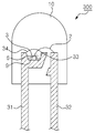
도 1은 본 발명의 일 실시예에 따른 발광 장치(100)를 설명하기 위한 단면도이다.
도 2는 본 발명의 다른 실시예에 따른 발광 장치(200)를 설명하기 위한 단면도이다.
도 3은 본 발명의 또 다른 실시예에 따른 발광 장치(300)를 설명하기 위한 단면도이다.
도 4는 본 발명의 또 다른 실시예에 따른 발광 장치(400)를 설명하기 위한 단면도이다.
도 5는 본 발명의 또 다른 실시예에 따른 발광 장치(500)를 설명하기 위한 단면도이다.
도 6은 상이한 조성을 갖는 Sr3Sio5 : Eu 형광체의 X-레이 회절 다이어그램이다.
도 7은 선택적으로 매우 낮은 Ca 분율을 갖는 발광체와 비교 발광체의 방출 스펙트럼이다.
도 8은 상이한 결정상(crystallographic phases)으로 형성된 회절 다이어그램으로부터 계산된 격자 상수 및 분율을 나타낸 표 1이다.
도 9는 낮은 Ca 분율을 갖는 전형적 형광체와 비교 재료들의 광학적 및 성능 파라미터들을 나타낸 표 2이다.
도 10은 낮은 Ca 분율을 갖는 본 발명에 따른 옥시오소실리케이트 형광체와 실리케이트 혼합 상의 습기 안정성 조사 결과를 나타낸 표 3이다.1 is a cross-sectional view illustrating a
2 is a cross-sectional view for describing a
3 is a cross-sectional view for describing a
4 is a cross-sectional view for describing a
5 is a cross-sectional view for describing a
6 is an X-ray diffraction diagram of Sr 3 Sio 5 : Eu phosphors with different compositions.
7 is emission spectra of emitters and comparative emitters, optionally with very low Ca fractions.
FIG. 8 is Table 1 showing the lattice constants and fractions calculated from diffraction diagrams formed with different crystallographic phases.
9 is Table 2 showing the optical and performance parameters of typical phosphors and comparative materials with low Ca fractions.
Figure 10 is a table 3 showing the results of the moisture stability investigation of the oxyosilicate phosphor and silicate mixture according to the present invention having a low Ca fraction.
이하, 첨부된 도면을 참조하여 본 발명의 실시예들에 따른 발광 장치를 구체적으로 설명한다.Hereinafter, a light emitting device according to embodiments of the present invention will be described in detail with reference to the accompanying drawings.
(발광 장치)(Light emitting device)
도 1은 본 발명의 일 실시예에 따른 발광 장치(100)를 설명하기 위한 단면도이다. 도 1은 적어도 하나의 발광 다이오드와 형광체가 조합된 칩형 패키지를 나타낸다.1 is a cross-sectional view illustrating a
도 1을 참조하면, 기판(1)의 양측 단부에 각각 전극패턴(5)이 형성되어 있고, 일측 전극패턴(5) 상에 1차 광을 발생시키는 발광 다이오드(6)가 실장되어 있다. 발광 다이오드(6)는 은(Ag) 에폭시와 같은 전도성 접착체(9)를 통해 전극패턴(5)에 실장되고, 도전성 와이어(2)를 통해 타측 전극패턴에 전기적으로 연결된다.Referring to FIG. 1,
발광 다이오드(6)는, 자외선 또는 가시광선 영역의 광을 방출하는 것으로, 질화갈륨 계열의 화합물 반도체로 제조될 수 있다. 특히, 상기 발광 다이오드(6)는 자외선 또는 청색광을 방출할 수 있다.The
발광 다이오드(6)가 실장된 기판(1) 상에서 형광체(3)가 상기 발광 다이오드(6)의 상면 및 측면에 도팅되어 있고, 경화성 수지로 형성된 몰딩부(10)가 상기 발광 다이오드(6)를 봉지한다. 여기서, 상기 형광체(3)가 상기 발광 다이오드(6) 근처에 도팅된 것으로 도시하였지만, 상기 형광체(3)는 몰딩부(10) 내에 전체적으로 고르게 분포될 수 있다. 상기 형광체(3)를 몰딩부(10) 내에 고르게 분포하는 방법은 US6,482,664호에 개시되어 있다.On the
한편, 상기 형광체(3)는 발광 다이오드(6) 주위에 배치되어 발광 다이오드로부터 방출된 광의 적어도 일부를 흡수하여 흡수광과 다른 파장의 광을 방출한다. 상기 형광체(3)에 대해서는 아래에서 상세히 설명된다.On the other hand, the
전극패턴(5)을 통해 발광 다이오드(6)에 외부 전원이 연결되고, 이에 따라, 발광 다이오드(6)에서 1차광이 발생된다. 형광체(3)는 발광 다이오드(6)에서 방출된 1차광 중 적어도 일부를 흡수하여 1차광에 비해 장파장인 2차광을 방출한다. 이에 따라, 발광 다이오드(6)에서 방출된 1차광 중 변환되지 않은 1차광과 형광체(3)에 의해 방출된 2차광들이 혼합된 혼합광이 발광 장치(100)의 외부로 방출되며, 이러한 혼합광에 의해 요구되는 색상의 광, 예컨대 백색광이 구현된다.An external power source is connected to the
상기 발광 장치(100)는 2개 이상의 발광 다이오드를 포함할 수 있다. 이들 발광 다이오드들은 서로 동일하거나, 서로 다른 파장의 광을 방출할 수 있다. 예컨대, 상기 발광 장치(100)는 자외선 또는 청색광을 방출하는 서로 동일 또는 서로 다른 발광 다이오드들을 포함할 수 있다. 또한, 상기 발광 장치(100)는 상기 형광체의 발광 피크 파장보다 더 장파장의 광을 방출하는 발광 다이오드를 포함할 수 있다. 이러한 장파장 발광 다이오드는 발광 장치(100)의 연색성을 향상시키기 위해 채택될 수 있다. 또한, 상기 발광 장치(100)는 상기 형광체(3) 이외에 다른 형광체를 더 포함할 수 있다. 상기 다른 형광체는, 특별히 한정되는 것은 아니며, 오소실리케이트 형광체, YAG 계열의 형광체 또는 티오갤레이트 형광체 등을 포함한다. 이에 따라, 발광 다이오드(6) 및 형광체의 적절한 선택에 의해 사용자가 요구하는 색상의 광을 쉽게 구현할 수 있다.The
도 2는 본 발명의 다른 실시예에 따른 발광 장치(200)를 설명하기 위한 단면도이다. 도 2는 리플렉터(21)를 구비하는 전형적인 탑형 패키지를 나타낸다.2 is a cross-sectional view for describing a
도 2를 참조하면, 발광 장치(200)는 앞에서의 발광 장치(100)와 유사한 구조를 가지며, 다만 기판(1) 상에 리플렉터(21)가 추가된다. 발광 다이오드(6)는 상기 리플렉터(21) 내에 실장된다. 리플렉터(21)는 발광 다이오드(6)에서 방출된 광을 반사시키어 특정 지향각 내의 휘도를 증가시킨다.Referring to FIG. 2, the
한편, 형광체(3)는, 도 1을 참조하여 설명한 바와 같이, 발광 다이오드(6) 주위에 배치되어 발광 다이오드로부터 방출된 광의 적어도 일부를 흡수하여 흡수광과 다른 파장의 광을 방출한다. 상기 형광체(3)는 리플렉터(21) 내에서 발광 다이오드(6) 상에 도팅되거나 경화성 수지 몰딩부(10) 내에 균일하게 분포될 수 있다. 상기 형광체(3)에 대해서는 아래에서 상세히 설명된다.On the other hand, the
상기 발광 장치(200) 또한, 도 1을 참조하여 설명한 바와 같이, 방출 파장이 서로 동일하거나 서로 다른 2 개 이상의 발광 다이오드들을 포함할 수 있으며, 상기 형광체(3) 이외에 다양한 형광체를 더 포함할 수 있다.The
한편, 도 1 및 도 2에 나타낸 발광 장치들(100, 200)은 열전도성이 우수한 금속성 재료의 기판(1), 예컨대 메탈 PCB를 사용할 수 있다. 이러한 기판은 발광 다이오드(6)에서 생성된 열을 쉽게 방출한다. 또한, 상기 기판(1)으로는 리드 단자들을 포함하는 리드프레임을 직접 사용할 수도 있다. 이러한 리드 프레임은 발광 다이오드를 봉지하는 몰딩부(10)에 의해 둘러싸여 지지될 수 있다.Meanwhile, the
한편, 도 2에서 기판(1)과 리플렉터(21)는 서로 다른 재질로 형성될 수 있으나, 이에 한정되는 것은 아니며, 동일한 재질로 형성될 수도 있다. 예컨대, 리드 단자들이 형성된 리드프레임을, PPA와 같은 플라스틱으로 삽입몰딩하여 기판(1)과 리플렉터(21)를 함께 형성할 수 있다. 그 후, 상기 리드 단자들을 절곡함으로써 전극패턴(5)이 형성된다.Meanwhile, in FIG. 2, the
도 3은 본 발명의 또 다른 실시예에 따른 발광 장치(300)를 설명하기 위한 단면도이다. 상기 발광 장치(300)는 일반적으로 발광 다이오드 램프로 알려져 있다.3 is a cross-sectional view for describing a
도 3을 참조하면, 발광 장치(300)는 한 쌍의 리드전극(31, 32)을 포함하며, 일측 리드전극(31) 상단부에 컵 형상을 갖는 컵부(33)가 형성되어 있다. 컵부(33) 내에 적어도 하나의 발광 다이오드(6)가 전도성 접착제(9)를 통해 실장되고, 도전성 와이어(2)를 통해 타측 리드전극(32)에 전기적으로 연결된다. 복수개의 발광 다이오드가 컵부(33) 내에 실장될 경우, 발광 다이오드들은 서로 동일하거나 서로 다른 파장의 광을 방출할 수 있다.Referring to FIG. 3, the
한편, 상기 발광 다이오드(6) 주위에 형광체(3)가 배치된다. 형광체(3)는, 도 1을 참조하여 설명한 바와 같이, 발광 다이오드(6) 주위에 배치되어 발광 다이오드로부터 방출된 광의 적어도 일부를 흡수하여 흡수광과 다른 파장의 광을 방출한다. 상기 형광체(3)는 컵부(33) 내에서 발광 다이오드(6) 상에 도팅되거나, 상기 컵부(33) 내부에 형성된 경화성 수지 몰딩부(34) 내에 균일하게 분포될 수 있다. 상기 형광체(3)에 대해서는 아래에서 상세히 설명한다.On the other hand, the
한편, 몰딩부(10)가 상기 발광 다이오드(6)와 형광체(3)를 봉지하며, 또한 상기 한 쌍의 리드전극(31, 32)의 부분들을 봉지한다. 상기 몰딩부(10)는 에폭시 또는 실리콘으로 형성될 수 있다.Meanwhile, the
한 쌍의 리드전극(31, 32)을 갖는 램프형 발광 장치(300)에 대해 도시 및 설명하였지만, 발광 장치(300) 내에 더 많은 리드전극들이 포함될 수 있다.Although the lamp type
도 4는 본 발명의 또 다른 실시예에 따른 발광 장치(400)를 설명하기 위한 단면도이다. 도 4는 고출력(high power)용 발광 다이오드 패키지를 나타낸다.4 is a cross-sectional view for describing a
도 4를 참조하면, 발광 장치(400)는 하우징(43) 내에 수용된 히트싱크(heat-sink, 41)를 포함한다. 상기 히트싱크(41)의 바닥면은 외부로 노출된다. 한편, 리드 단자들(44)이 하우징(43) 내에 노출되어 있으며, 하우징을 통해 외부로 연장된다. 히트싱크(41)의 상면에 적어도 하나의 발광 다이오드(6)가 도전성 접착제(9)를 통해 실장되고, 도전성 와이어를 통해 리드 단자들(44) 중 하나에 전기적으로 연결된다. 또한, 다른 도전성 와이어가 리드 단자들(44) 중 다른 하나와 히트싱크(41)을 연결하며, 그 결과, 상기 발광 다이오드(6)가 두 개의 리드단자들(44)에 각각 전기적으로 연결된다.Referring to FIG. 4, the
한편, 상기 히트싱크(41) 상의 발광 다이오드(6) 주위에 형광체(3)가 배치된다. 형광체(3)는, 도 1을 참조하여 설명한 바와 같이, 발광 다이오드(6) 주위에 배치되어 발광 다이오드로부터 방출된 광의 적어도 일부를 흡수하여 흡수광과 다른 파장의 광을 방출한다. 상기 형광체(3)은 히트싱크(41) 상에서 발광 다이오드(6) 상에 도팅되거나, 상기 발광 다이오드를 덮는 몰딩부(도시하지 않음) 내에 고르게 분포될 수 있다. 상기 형광체(3)에 대해서는 아래에서 상세히 설명한다.On the other hand, the
도 5는 본 발명의 또 다른 실시예에 따른 발광 장치(500)를 설명하기 위한 단면도이다.5 is a cross-sectional view for describing a
도 5를 참조하면, 발광 장치(500)는 하우징(53) 및 상기 하우징에 결합되고, 서로 절연된 복수개의 히트싱크들(51, 52)을 포함한다. 상기 히트싱크들(51, 52) 상에 각각 발광 다이오드들(6, 7)이 도전성 접착제(9)를 통해 실장되고 도전성 와이어(도시하지 않음)를 통해 리드단자들(54)에 전기적으로 연결된다. 상기 리드단자들(54)은 하우징 내에서 외부로 연장된다. 도면에서 두개의 리드단자들(54)을 도시하였지만, 더 많은 수의 리드단자들이 마련될 수 있다.Referring to FIG. 5, the
한편, 형광체(3)가 상기 발광 다이오드들(6, 7) 중 적어도 하나의 주위에 도 4를 참조하여 설명한 바와 같이 배치된다. 상기 형광체(3)에 대해서는 아래에서 상세히 설명한다.On the other hand, the
본 발명의 실시예들에 있어서, 발광 다이오드(6)가 도전성 접착제(9)를 통해 기판(1) 또는 히트싱크에 실장되고 하나의 도전성 와이어를 통해 전극 패턴 또는 리드단자에 전기적으로 연결되는 것으로 설명하였지만, 이러한 예는 상기 발광 다이오드(6)가 "1본드 다이", 즉 그 상부측 및 하부측에 각각 전극을 갖는 경우에 한정된다. 예컨대, 상기 발광 다이오드(6)가 상부측에 두 개의 전극을 갖는 "2본드 다이"인 경우, 상기 발광 다이오드(6)는 두 개의 도전성 와이어에 의해 각각 전극패턴들 또는 리드단자들에 전기적으로 연결될 수 있다. 이 경우, 접착제는 도전성일 필요가 없다.In the embodiments of the present invention, the
본 발명의 실시예들에 있어서, 상기 발광 다이오드(6)는 (Al, Ga, In)N 계열의 화합물 반도체로 형성된 발광 다이오드일 수 있다.In the embodiments of the present invention, the
상기 발광 다이오드(6)는 n형 반도체와 p형 반도체층 사이에 단일의 활성 영역을 갖는, 예컨대, 더블 헤테로 구조, 단일양자우물 구조, 다중양자우물 구조의 발광 다이오드일 수 있다.The
또한, 상기 발광 다이오드(6)는 단일 기판 상에 서로 이격된 복수개의 발광셀들을 구비할 수 있다. 상기 발광셀들은 각각 활성 영역을 구비하며, 이들 발광셀들이 배선을 통해 전기적으로 직렬 및/또는 병렬로 연결될 수 있다. 특히, 이들 발광셀들을 이용하여 교류전원하에서 직접 구동될 수 있는 발광 다이오드가 제공될 수 있다. 이러한 교류용 발광 다이오드는, 단일 기판 상에 서로 연결된 브리지 정류기와 발광셀들의 직렬 어레이를 형성함으로써, 또는 단일 기판 상에 서로 역병렬로 연결된 발광셀들의 직렬 어레이들을 형성함으로써 외부의 직류-교류 변환기 없이 교류 전원에 연결되어 구동될 수 있다. 상기 교류용 발광 다이오드는 복수개의 발광셀들을 배선을 통해 직렬로 연결하므로 동작 전압을 가정용 전원의 전압, 예컨대 110V 또는 220V의 전압으로 상승시킬 수 있으며, 따라서 가정용 전원에 의해 동작될 수 있는 발광 장치가 제공될 수 있다.In addition, the
또한, 상기 형광체(3)는 발광 다이오드(6)와 상기 발광 다이오드가 실장되는 기판(1) 또는 히트싱크 사이에 배치될 수도 있으며, 접착제(9) 내에 분포될 수도 있다. 이러한 형광체(3)는 발광 다이오드(6)에서 아래로 방출된 광의 적어도 일부를 흡수하여 다른 파장의 광을 방출한다.In addition, the
위에서, 발광 장치의 몇 가지 구조에 대해 설명하였지만, 본 발명이 이들 구조에 한정되는 것은 아니며, 발광 다이오드의 종류, 전기적 연결 방식, 요구되는 광의 지향각 및 발광 장치의 사용 목적 등에 따라 그 구조가 다양하게 변형될 수 있다.Although some structures of the light emitting device have been described above, the present invention is not limited to these structures, and the structures vary depending on the type of light emitting diode, the electrical connection method, the required angle of light, and the purpose of use of the light emitting device. Can be modified.
(형광체)(Phosphor)
이하, 본 발명의 실시예들에 사용되는 형광체(3)에 대해 설명한다.Hereinafter, the
생성된 방사 부하에 대한 향상된 안정성 및 대기 습도의 영향에 대한 내성을 갖는 본 발명에 따른 스트론륨 옥시오소실리케이트 형광체는 일반식 Sr3 -x-y-zCaxMII ySiO5 : Euz에 의해 표현될 수 있는 바, 칼슘 몰분율 x를 0 내지 0.05 사이 값으로 할 수 있고, 한편, 유로퓸 몰분율 z에 대하여 ≤ 0.25의 범위의 값이 전형적이다. 최고 활성체(activator) 농도는 형광체의 특정 사용 조건에 따라 다르고 실험적으로 용이하게 결정될 수 있다.The strontium oxyosilicate phosphors according to the invention with improved stability to the resulting radiation load and resistance to the effects of atmospheric humidity can be represented by the general formula Sr 3 -xyz Ca x M II y SiO 5 : Eu z As can be seen, the calcium mole fraction x can be a value between 0 and 0.05, while a value in the range of <0.25 is typical for the europium mole fraction z. The highest activator concentration depends on the specific conditions of use of the phosphor and can be easily determined experimentally.
상기 일반식에서, MII 는 마그네슘(mg), 바륨(Ba), 구리(Cu), 아연(Zn) 및 망간(Mn) 원소로 이루어진 군에서 선택된 2가 금속 이온들을 나타내고, 이들 이온들은 선택적으로 모 형광체 격자내로 추가적으로 함유될 수 있다. 바륨의 경우에는, 스트론튬에 대한 완전한 대체가 가능하고; 스트론튬에 부가하여 함유되는 다른 2가 금속 이온들의 분율은 y = 0.5까지 일 수 있다.In the general formula, M II represents divalent metal ions selected from the group consisting of magnesium (mg), barium (Ba), copper (Cu), zinc (Zn) and manganese (Mn) elements, and these ions are selectively It may be further contained into the phosphor lattice. In the case of barium, a complete replacement for strontium is possible; The fraction of other divalent metal ions contained in addition to strontium can be up to y = 0.5.
유로퓸(Eu)과 별도로 그리고 이 도핑 원소에 선택적 추가적으로, 원리적으로 예를 들어, 사마륨(Sm) 또는 이테르븀(Yb)과 같은 2가 희토류 이온, 또는 예를 들어 세륨 이온(Ce3 +)과 같은 특정 3가 희토류 이온이 또한 활성체(activator)로서 적합하다.Europium (Eu) and additionally and optionally additionally, as principle, for example, samarium (Sm), or ytterbium (Yb) 2 has a rare-earth ion, or for example, cerium ions, such as (Ce 3 +) in the doping element Certain trivalent rare earth ions are also suitable as activators.
발광 성질 및 안정성 거동을 최적화하는 목적으로, 이러한 형광체는 또한 그들의 조성물에서 추가 변형을 겪는다. 따라서, 예를 들어, 실리콘(Si)은 게르마늄(Ge)에 의해 및/또는, 알루미늄(Al), 갈륨(Ga), 붕소(B) 또는 인(P)에 의해 대체될 수 있으나, 마지막으로 언급된 경우에서는 필요한 경우 취해질 수 있는 전하 균형(charge balance)을 유지하기 위한 적절한 조치를 필요하다면 취해야 한다. 이것은 또한 예를 들어, 리튬(Li), 나트륨(Na) 및 칼륨(K)과 같은 1가 양이온 또는, 플루오린(F), 염소(Cl), 브롬(Br) 또는 요오드(I)와 같은 음이온을 모 격자 내로 추가로 함유시키는 것으로 이루어질 수 있다.
For the purpose of optimizing luminescent properties and stability behavior, these phosphors also undergo further modifications in their compositions. Thus, for example, silicon (Si) may be replaced by germanium (Ge) and / or by aluminum (Al), gallium (Ga), boron (B) or phosphorus (P), but last mentioned Where appropriate, appropriate measures should be taken if necessary to maintain a charge balance that can be taken if necessary. It is also for example monovalent cations such as lithium (Li), sodium (Na) and potassium (K) or anions such as fluorine (F), chlorine (Cl), bromine (Br) or iodine (I) May be further contained into the parent lattice.
바람직한 실시예에서, 생성된 방사 부하에 대한 향상된 안정성 및 대기 습도의 영향에 대한 내성을 갖는 형광체는 화학식 Sr3 -x-y- zCaxBaySiO5 : Euz 를 갖는데, 여기에서 본 발명에 따른 몰분율은 0 < x ≤ 0.05, 0 ≤ y ≤ 0.5, 및 z ≤ 0.25이다.In a preferred embodiment, the phosphor having improved stability to the resulting radiation load and resistance to the effects of atmospheric humidity has the formula Sr 3 -xy- z Ca x Ba y SiO 5 : Eu z , according to the invention The molar fractions are 0 <x <0.05, 0 <y <0.5, and z <0.25.
높은 에너지 방사로 여기하면, 형광체는 그들의 특정 화학적 조성에 따라 스펙트럼의 가시 부분, 바람직하게는 560 내지 620nm 사이의 범위 내에서 방출한다. Eu2+ 여기 발광은 220nm의 자외선에서 550nm의 가시 광선 범위이고, 이는 본 발명의 발광체가 녹색 여기 방사로도 여기되어 효율적인 황색 내지 오렌지색 또는 적색 발광을 발생할 수 있다는 것을 뜻한다. 또한, 강도가 높고 기술적으로 사용가능한 발광 과정은 본 발명에 따른 매우 낮은 Ca 분율을 갖는 형광체를 전자 빔, X-레이 빔 또는 감마 방사로 조사할 때도 발생한다.When excited with high energy radiation, the phosphors emit within the visible portion of the spectrum, preferably between 560 and 620 nm, depending on their specific chemical composition. Eu 2+ excitation light emission ranges from 220 nm ultraviolet light to 550 nm visible light, which means that the light emitter of the present invention can also be excited by green excitation radiation to produce efficient yellow to orange or red light emission. In addition, a high intensity and technically usable luminescence process also occurs when irradiating phosphors with very low Ca fractions according to the invention with electron beams, X-ray beams or gamma radiation.
향상된 발광 성질들 때문에, 본 발명에 따른 매우 낮은 Ca 분율을 갖는 형광체는 자외선, 청색 또는 녹색 방사를 바람직하게 황색, 오렌지색 및 적색 스펙트럼 범위에서 방출되는 긴 파장 가시광선으로 변환시키는 방사 변환기로서 사용될 수 있다. 상기 형광체는 단독 또는 다른 청색, 녹색, 황색 및/또는 적색 방출 형광체와 배합하여 사용될 수 있다.Because of the improved luminescent properties, the phosphors having a very low Ca fraction according to the invention can be used as radiation converters which convert ultraviolet, blue or green radiation into long wavelength visible light which is preferably emitted in the yellow, orange and red spectral ranges. . The phosphor may be used alone or in combination with other blue, green, yellow and / or red emitting phosphors.
이러한 형광체들은 바람직하게 출발 물질로 사용되는 알칼리토금속 탄산염 또는 상응하는 산화물과 미세하게 나뉜 SiO2 사이의 선택적으로 다단계 고온 고상 반응에 기반하여 조성되는데, 반응을 촉진하고 생성된 발광체들의 입자 크기 분포를 조절하기 위하여 일정 양의 플럭스 또는 예를 들어 NH4Cl 과 같은 미넬랄화 첨가제, NH4F 또는 특정 알칼리금속 또는 알칼리토금속 플루오르화물을 상기 반응 혼합물에 또한 첨가할 수 있다. 이러한 출발 물질들은 철저히 혼합된 후 비활성 또는 환원 분위기에서 1300 내지 1700℃의 온도에서 1 내지 48시간 동안 소성된다. 형광체의 성질을 최적화시키기 위한 목적의 이 주 소성 상은 선택적으로 또한 상이한 온도 범위에서 복수의 소성 단계를 가질 수 있다. 소성 공정이 끝난 후, 샘플은 상온으로 냉각되고, 예를 들어, 플럭스 잔류물 제거, 표면 결함의 최소화 또는 입자 크기 분포의 정밀한 조정을 목적으로 하는 적절한 후처리 공정을 하게 된다. 미세하게 나뉜 실리카 대신에, 질화규소(Si3N4)가 또한 사용되는 알칼리토금속 화합물과 반응하기 위한 반응체(reactant)로서 대안적으로 사용될 수 있다.These phosphors are preferably formed on the basis of an optional multistage high temperature solid state reaction between alkaline earth metal carbonates or corresponding oxides and finely divided SiO 2 used as starting materials, which facilitate the reaction and control the particle size distribution of the resulting light emitters. To this end an amount of flux or a mineralization additive such as NH 4 Cl, NH 4 F or certain alkali or alkaline earth metal fluorides can also be added to the reaction mixture. These starting materials are thoroughly mixed and then fired for 1 to 48 hours at a temperature of 1300 to 1700 ° C. in an inert or reducing atmosphere. This main firing phase for the purpose of optimizing the properties of the phosphor can optionally also have a plurality of firing steps in different temperature ranges. After the firing process is finished, the sample is cooled to room temperature and subjected to a suitable post-treatment process, for example, for the purpose of removing flux residues, minimizing surface defects or precisely adjusting the particle size distribution. Instead of finely divided silica, silicon nitride (Si 3 N 4 ) may also be used alternatively as a reactant for reacting with the alkaline earth metal compound used.
이 맥락에서, 본 발명에 따른 형광체의 합성이 상술한 제조 과정들에 한정되는 것은 아니다.In this context, the synthesis of the phosphor according to the invention is not limited to the above-described manufacturing processes.
낮은 Ca 분율을 갖는 형광체의 조성에 대한 상세한 정보가 아래 개시된다.
Detailed information on the composition of phosphors with low Ca fraction is disclosed below.
실험예Experimental Example 1 One
조성 Sr2 .9285Ca0 .03Cu0 .0015SiO5 : Eu0 .04의 낮은 Ca 분율을 갖는 형광체의 제조를 위하여, 432.4g 의 SrCO3, 3.0g의 CaCO3, 0.12g의 CuO, 7.04g의 Eu2O3 및 60.94g의 SiO2 가 출발 물질로서 사용되고, 여기에 1.5g의 NH4F가 플럭스로서 첨가된다. 완전히 균질화한 후에, 배치(batch) 혼합물이 고온 로(furnace)에 위치한 코런덤(corundum) 도가니로 옮겨진다. 거기서, 고체 혼합물은 1200℃에서 3 시간 유지하는 제1 단계 및 1550℃에서 5시간 유지하는 제2 단계를 갖는 소성 형태로 실행된다. 소성은, 1550℃ 램프(ramp)가 도달할 때까지는 순수 산소 내에서, 1550℃ 단계 동안은 20% 수소를 포함하는 N2/H2 혼합 가스에서 수행된다. 냉각된 소성 재료의 후처리는 밀링, 세척 공정의 수행 및 최종 생성물의 건조 및 체질을 포함한다.
Composition Sr 2 .9285 Ca 0 .03 Cu 0 .0015 SiO 5: Eu to the fluorescent substance manufactured having a low fraction of the Ca 0 .04, 432.4g of SrCO 3, CaCO 3, 0.12g of 3.0g CuO, 7.04 g of Eu 2 O 3 and 60.94 g of SiO 2 are used as starting materials, to which 1.5 g of NH 4 F is added as flux. After complete homogenization, the batch mixture is transferred to a corundum crucible placed in a hot furnace. There, the solid mixture is carried out in a fired form with a first step of holding at 1200 ° C. for 3 hours and a second step of holding at 1550 ° C. for 5 hours. Firing is carried out in pure oxygen until a 1550 ° C. ramp is reached and in a N 2 / H 2 mixed gas containing 20% hydrogen during the 1550 ° C. step. Post-treatment of the cooled calcined material includes milling, performing the washing process and drying and sieving the final product.
실험예Experimental Example 2 2
본 발명의 조성 Sr2 .91Ca0 .04Ba0 .01SiO5 : Eu0 . 04 의 알칼리토금속 옥시오소실리케이트 형광체의 제조를 위하여, 429.6g 의 SrCO3, 1.97g의 BaCO3, 4.01g의 CaCO3, 7.04g의 Eu2O3, 60.9g의 SiO2 및 0.54g의 NH4Cl이 완전히 혼합된 후 20% 수소를 갖는 N2/H2 분위기에서 1380℃의 온도에서 6시간 동안 소성된다. 소성 과정이 끝난 후, 소성된 재료는 밀링에 의해 균질화되고 이후 적어도 5%의 수소 농도를 갖는 감소된 N2/H2 분위기의 1350℃에서 다시 두 시간 동안 열처리를 수행한다. 합성된 형광체 샘플의 최종 후처리는 실험예 1에 기재된 방식으로 수행된다.
The composition of the present invention, Sr 2 .91 Ca 0 .04 Ba 0 .01 SiO 5:
도 6은 첨가된 칼슘의 분율이 서로 상이한 유로퓸-활성 스트론튬 옥시오소실리케이트 형광체의 X-레이 회절 다이어그램을 도시한다. 회절 다이어그램 1은 비교 물질 Sr2 .95Ba0 .01Eu0 .04SiO5 에 관한 것이다. 회절 다이어그램 2는 Sr3SiO5 형광체 Sr2.95Ba0.01Ca0.02Eu0.04SiO5에 적용한다. 회절 다이어그램 3은 Sr3SiO5 형광체 Sr2.8Ba0.01Ca0.15Eu0.04SiO5를 도시하고, 다이어그램에서 화살표들은 Sr2SiO4의 외부(foreign) 상 구조의 반사 특성을 표시한다.FIG. 6 shows an X-ray diffraction diagram of europium-active strontium oxyosilicate phosphors with different fractions of added calcium. Diffraction Diagram 1 relates to a comparison material Sr 2 .95 Ba 0 .01 Eu 0 .04
도 7은 선택적으로 매우 낮은 칼슘 비율을 갖는 발광체 및 비교 물질의 방출 스펙트럼을 도시한다. 비교 물질 Sr2 .95Ba0 .01Eu0 .04SiO5은 스펙트럼 1을 가진다. Sr3SiO5 형광체 Sr2 .95Ba0 .01Ca0 .02Eu0 .04SiO5의 스펙트럼은 2로 특징되고 Sr3SiO5 형광체 Sr2.8Ba0.01Ca0.15Eu0.04SiO5는 3에 의해 특징된다.7 shows emission spectra of emitters and comparative materials, optionally with very low calcium ratios. Comparative material Sr 2 .95 Ba 0 .01 Eu 0 .04
순수 Sr3SiO5의 경우 및 x = 0.05의 칼슘 몰분율을 갖는 Sr3 -x-y- zCaxBa0 .01SiO5 모 격자의 경우 모두에서, 문헌들로부터 공지된 Sr3SiO5 구조 유형의 반사가 회절도에서 배타적으로 발견되고, 칼슘 치환된 물질의 회절 각도는 예상대로 순수 Sr3SiO5 상의 회절 각도에 대해 상대적으로 약간 이동한다. 대조적으로, x = 0.1의 칼슘 분율을 갖는 Sr3 -x-y- zCaxBa0 .01SiO5 : Euz 형광체의 제조물에서, 그 물질의 회절도는 Sr2SiO4 형태의 오소실리케이트 화합물에 대하여 특징적인 반사가 Sr3SiO5 상에 대한 반사에 추가하여 고강도로 수득되었다.Pure Sr 3 SiO 5 and in the case x = 3 having a Sr 0.05 Ca mole fraction of -xy- z Ca x Ba 0 .01 SiO 5 the base in both the case of a grating, known from the literature Sr 3 SiO 5 structural type of reflection Is found exclusively in the diffractogram, and the diffraction angle of the calcium substituted material shifts slightly relative to the diffraction angle of the pure Sr 3 SiO 5 phase as expected. In contrast, x = Sr 3 -xy- z Ca
도 8의 표 1은 실험예 1에 기술한 일련의 제조 방법과 유사하게 합성되고, 칼슘 양이 증가하여 Sr3SiO5 매질에 함유되는 일련의 화합물의, 분율 다이어그램으로부터 계산된, 상이한 결정상의 분율 및 격자 상수를 열거한다. 표 1에 도시된 바와 같이, 추가되는 칼슘의 증가는 처음에는 원칙적으로 Sr3SiO5 상의 격자 상수 감소로 이어지는데, 본 발명에 따른 x < 0.05 의 칼슘 몰분율을 갖는 발광체에 대해 상응하는 값은 서로 아주 약간씩 상이하다. 공지된 문헌의 값 및 기준 재료의 격자 상수로부터 더 큰 편차는 x > 0.05의 칼슘 함유 경우에서만 발생한다.Table 1 of FIG. 8 shows the fractions of the different crystal phases, synthesized similarly to the series of preparation methods described in Experimental Example 1, and calculated from the fractional diagrams of the series of compounds with an increased amount of calcium contained in the Sr 3 SiO 5 medium. And lattice constants. As shown in Table 1, the increase in the added calcium initially leads to a reduction in the lattice constant of the Sr 3 SiO 5 phase in principle, with corresponding values for the phosphors having a calcium mole fraction of x <0.05 according to the invention being very different from each other. Slightly different Larger deviations from the values of known literature and the lattice constants of the reference material occur only in the case of calcium containing x> 0.05.
그러나 증가된 칼슘 농도의 효력은 격자 상수의 추가 감소에 한정되지 않는다. 증가된 칼슘 첨가의 경우를 결과하는 재료들의 퍼센티지 상(phase) 조성에 대하여 표 1에 나열된 데이터에 의해 도시되는 바와 같이, Sr3SiO5 및 Sr2SiO4 상의 혼합물이 칼슘 분율 증가에 따라 증가하도록 형성되는데, Sr3SiO5 구조 유형의 옥시오소실리케이트 대신에 오소실리케이트 상의 분율이 전체 혼합물에 기초해서 x = 0.1의 칼슘 분율의 경우에 이미 42%이다.However, the effect of increased calcium concentration is not limited to further reductions of lattice constants. As shown by the data listed in Table 1 for the percentage phase composition of the materials resulting in increased calcium addition, the mixture of Sr 3 SiO 5 and Sr 2 SiO 4 phases increased with increasing calcium fraction. Formed, the fraction of the onosilicate phase instead of the oxyosilicate of the Sr 3 SiO 5 structure type is already 42% for the calcium fraction of x = 0.1 based on the total mixture.
표 1로부터 칼슘 없는 기준 재료뿐만 아니라 본 발명에 따른 낮은 칼슘 함유량을 갖는 옥시오소실리케이트 형광체가 미량의 상응하는 오소실리케이트 외부 상들을 갖는다는 것이 또한 명백하다. 이 현상은 공지되어 있고 상응하는 소성 재료들의 냉각시 부분적 상 변화에 기인할 수 있는데, 이는 매우 큰 노력에 의해서만 형광체의 고온 합성에서 배제될 수 있다. 그러나, 옥시오소실리케이트 발광체의 효율은 외부 상의 이 극단적으로 작은 분율에 의해 영향을 받지 않는다는 것이 증명된 것으로 간주될 수 있다.From Table 1 it is also clear that the calcium free reference material as well as the low calcium content oxyosilicate phosphors according to the invention have trace amounts of the corresponding osilicate external phases. This phenomenon is known and can be attributed to the partial phase change upon cooling of the corresponding plastic materials, which can only be excluded from the high temperature synthesis of the phosphor with very large effort. However, it can be considered proven that the efficiency of the oxyosilicate emitter is not affected by this extremely small fraction of the external phase.
본 발명의 형광체의 발광 효율들 및 이의 온도 의존성은 모두 상업적으로 입수가능한 Sr3SiO5 : Eu 형광체보다 열등하지 않다는 것이 유리하게 언급될 수 있다.It can be advantageously mentioned that the luminous efficiencies of the phosphors of the invention and their temperature dependence are not inferior to commercially available Sr 3 SiO 5 : Eu phosphors.
상응하는 측정치에 대하여 도 9의 표 2에 나열된 결과에 의해 도시되는 바와 같이, 상대적 또는 높은 발광 출력을 갖는 형광체가 실험예 1 및 2에 설명된 제조 방법에 기반하여 제조될 수 있다.As shown by the results listed in Table 2 of FIG. 9 for the corresponding measurements, phosphors having a relatively or high luminous output can be prepared based on the manufacturing methods described in Experimental Examples 1 and 2. FIG.
상기 형광체의 경우에, 칼슘 함유량의 증가에 따라 방출 최대치에서 더 큰 파장으로의 약간의 이동이 초기에 발견된다. 이는 격자 상수의 감소 때문에 증가하는 결정장(crystal field) 때문일 수 있다. 결정학적 발견들과 함께, 발광체의 광학적 파라미터의 이러한 이동은 또한 본 발명에 따른 첨가된 칼슘의 양이 또한 설명된 농도 범위 내에서 실제로 Sr3SiO5 격자로 함유되었다는 신뢰할만한 지표이다.In the case of the phosphor, some shift from the emission maximum to a larger wavelength is initially found with increasing calcium content. This may be due to the increasing crystal field due to the reduction of the lattice constant. In conjunction with crystallographic findings, this shift in the optical parameters of the illuminant is also a reliable indicator that the amount of calcium added according to the invention was also actually contained in the Sr 3 SiO 5 lattice within the concentration ranges described.
다른 한편으로 x = 0.05의 영역을 초과하는 칼슘 첨가는 실리케이트 혼합 상을 야기하는데, 이의 발광 성질은 감소된 효율, 넓어진 방출 스펙트럼 및 감소된 온도 안정성으로 특징된다. 본 발명에 따른 낮은 Ca 분율을 갖는 형광체의 방출 스펙트럼이 기준 재료 및 칼슘이 많이 혼합된 상과 비교되어 있는 도 7로부터 또한 명백하다.On the other hand, addition of calcium above the region of x = 0.05 results in a silicate mixed phase whose luminescent properties are characterized by reduced efficiency, broader emission spectrum and reduced temperature stability. It is also apparent from FIG. 7 in which the emission spectrum of the phosphor having a low Ca fraction according to the invention is compared with the reference material and the calcium-rich phase.
상기 재료들의 습도 안정성을 평가하기 위하여, 해당 형광체 샘플이 조건화 된 챔버에서 온도 85℃ 및 상대 습도 85%에서 7일의 기간 동안 저장된다. 그 후, 상기 발광체들이 150℃에서 건조되고, 그 후, 발광 수율의 비교 측정이 수행된다. 그러한 검사의 전형적인 결과가 도 10의 표 3에 열거되어 있다. 표 3의 데이터는 상업적으로 입수가능한 Sr3SiO5 : Eu 및 기준 목적으로 제조된 (Sr2 .95Ba0 .01Eu0 .04)SiO5 형광체는 모두 습도 분위기에서의 저장을 포함하는 상기 설명된 과정후에 원래 발광 효율의 약 70%만을 갖는 것을 보여준다. To assess the humidity stability of the materials, the corresponding phosphor sample is stored for 7 days at a temperature of 85 ° C. and a relative humidity of 85% in a conditioned chamber. Thereafter, the luminous bodies are dried at 150 ° C., and then a comparative measurement of the luminous yield is performed. Typical results of such a test are listed in Table 3 of FIG. The data in Table 3 are commercially available Sr 3 SiO 5: Eu, and the description made of the reference object (2 Sr .95 Ba .01 0 .04 0 Eu) phosphor SiO 5 are all included in the storage humidity atmosphere After about 70% of the original luminous efficiency.
그러나 놀랍게도, 본 발명에 따라 스트론튬의 선택적으로 작은 분율이 칼슘으로 대체된 Sr3SiO5 : Eu 유형의 유로퓸-도핑된 옥시오소실리케이트 형광체는, Sr3SiO5 구조의 형성에 악영향을 끼치지 않으면서, 상당히 향상된 습도 내성을 갖는다. 85℃/85% 상대습도 분위기에서 7일 동안 저장한 후에, 90%보다 큰 발광 수율, 최적화된 샘플의 경우에는 95%보다 큰 발광 효율이 여전히 발견된다.Surprisingly, however, the Sr 3 SiO 5 : Europium-doped oxyososilicate phosphor of the selectively small fraction of strontium replaced by calcium according to the invention does not adversely affect the formation of the Sr 3 SiO 5 structure. , Has significantly improved humidity resistance. After 7 days of storage in an 85 ° C./85% relative humidity atmosphere, luminous yields greater than 90%, luminous efficiency greater than 95% are still found for optimized samples.
Claims (16)
상기 발광 다이오드 주위에 배치되어 상기 발광 다이오드로부터 방출된 광의 적어도 일부를 흡수하여 흡수광과 다른 파장의 광을 방출하는 형광체를 포함하고,
상기 형광체는 0 내지 0.05 사이의 값을 갖는 칼슘 몰분율 x가 일반식 Sr3 -x-y-zCaxMII ySiO5 : Euz 를 갖는 실리케이트 형광체로 첨가된 것을 특징으로 하는 발광 장치.Light emitting diodes; And
A phosphor disposed around the light emitting diode to absorb at least a portion of the light emitted from the light emitting diode to emit light having a wavelength different from that of the absorbed light;
The phosphor is a light emitting device, characterized in that the calcium mole fraction x having a value between 0 and 0.05 is added as a silicate phosphor having the general formula Sr 3 -xyz Ca x M II y SiO 5 : Eu z .
상기 발광 다이오드는 상기 기판 상에 실장된 발광 장치.The method of claim 10, wherein the package comprises a substrate,
The light emitting diode is mounted on the substrate.
상기 형광체는 상기 몰딩부 내에 분포되어 있는 발광 장치.The method of claim 13, further comprising a molding unit encapsulating the light emitting diode on the substrate,
The phosphor is distributed in the molding portion.
상기 발광 다이오드는 상기 히트싱크 상에 실장된 발광 장치.The device of claim 10, wherein the package includes a heat sink,
The light emitting diode is mounted on the heat sink.
Priority Applications (7)
| Application Number | Priority Date | Filing Date | Title |
|---|---|---|---|
| KR1020100035190A KR101670947B1 (en) | 2010-04-16 | 2010-04-16 | Light emitting device having strontium oxyorthosilicate type phosphors |
| EP10839706.8A EP2516584B1 (en) | 2009-12-21 | 2010-12-14 | Light emitting device having strontium/barium oxyorthosilicate type phosphors |
| JP2012545843A JP5748769B2 (en) | 2009-12-21 | 2010-12-14 | Light emitting device having phosphor of strontium oxyorthosilicate type |
| CN201080058655.4A CN102666781B (en) | 2009-12-21 | 2010-12-14 | Light emitting device with strontium oxyorthosilicate type phosphor |
| PCT/KR2010/008922 WO2011078509A2 (en) | 2009-12-21 | 2010-12-14 | Light emitting device having strontium oxyorthosilicate type phosphors |
| TW099144790A TWI456030B (en) | 2009-12-21 | 2010-12-20 | Light-emitting element having bismuth oxyhydroxide type phosphor |
| US12/972,996 US8963173B2 (en) | 2009-12-21 | 2010-12-20 | Light emitting device having strontium oxyorthosilicate type phosphors |
Applications Claiming Priority (1)
| Application Number | Priority Date | Filing Date | Title |
|---|---|---|---|
| KR1020100035190A KR101670947B1 (en) | 2010-04-16 | 2010-04-16 | Light emitting device having strontium oxyorthosilicate type phosphors |
Publications (2)
| Publication Number | Publication Date |
|---|---|
| KR20110115716A true KR20110115716A (en) | 2011-10-24 |
| KR101670947B1 KR101670947B1 (en) | 2016-11-01 |
Family
ID=45030261
Family Applications (1)
| Application Number | Title | Priority Date | Filing Date |
|---|---|---|---|
| KR1020100035190A Expired - Fee Related KR101670947B1 (en) | 2009-12-21 | 2010-04-16 | Light emitting device having strontium oxyorthosilicate type phosphors |
Country Status (1)
| Country | Link |
|---|---|
| KR (1) | KR101670947B1 (en) |
Citations (4)
| Publication number | Priority date | Publication date | Assignee | Title |
|---|---|---|---|---|
| WO2004085570A1 (en) | 2003-03-28 | 2004-10-07 | Korea Research Institute Of Chemical Technology | Strontium silicate-based phosphor, fabrication method thereof, and led using the phosphor |
| WO2006081803A1 (en) | 2005-02-04 | 2006-08-10 | Patent-Treuhand-Gesellschaft für elektrische Glühlampen mbH | Illuminant emitting yellow light and light source provided with such an illuminant |
| WO2006131795A1 (en) * | 2005-06-06 | 2006-12-14 | Acol Technologies Sa | Wavelenght shifting compositions |
| KR20080085360A (en) * | 2007-03-19 | 2008-09-24 | 서울반도체 주식회사 | Light emitting device with various color temperatures |
-
2010
- 2010-04-16 KR KR1020100035190A patent/KR101670947B1/en not_active Expired - Fee Related
Patent Citations (4)
| Publication number | Priority date | Publication date | Assignee | Title |
|---|---|---|---|---|
| WO2004085570A1 (en) | 2003-03-28 | 2004-10-07 | Korea Research Institute Of Chemical Technology | Strontium silicate-based phosphor, fabrication method thereof, and led using the phosphor |
| WO2006081803A1 (en) | 2005-02-04 | 2006-08-10 | Patent-Treuhand-Gesellschaft für elektrische Glühlampen mbH | Illuminant emitting yellow light and light source provided with such an illuminant |
| WO2006131795A1 (en) * | 2005-06-06 | 2006-12-14 | Acol Technologies Sa | Wavelenght shifting compositions |
| KR20080085360A (en) * | 2007-03-19 | 2008-09-24 | 서울반도체 주식회사 | Light emitting device with various color temperatures |
Non-Patent Citations (2)
| Title |
|---|
| Jee, Soon-Duc, et al., in J. Mater. Sci. 41 (2006), 3139-41 |
| Park, Joung-Kyu, et al., in Appl., Phys. Lett. 84 (2004), 1647-49 |
Also Published As
| Publication number | Publication date |
|---|---|
| KR101670947B1 (en) | 2016-11-01 |
Similar Documents
| Publication | Publication Date | Title |
|---|---|---|
| KR101055769B1 (en) | Light-emitting device adopting non-stoichiometric tetra-alkaline earth silicate phosphor | |
| JP5236397B2 (en) | Light emitting device using non-stoichiometric tetragonal alkaline earth silicate phosphor | |
| JP4159542B2 (en) | Light emitting device | |
| US8053798B2 (en) | Light emitting device | |
| KR101802996B1 (en) | Means for improving stability to the resulting radiation load and resistance to the influence of atmospheric humidity in the case of strontium oxyorthosilicate phosphors | |
| KR101055762B1 (en) | Light-emitting device employing a light-emitting material having an oxyosilicate light emitter | |
| JP2012246462A (en) | Light emitting device | |
| CN102804418B (en) | Adopt the light-emitting device with the luminescent substance of oxygen orthosilicate luminous element | |
| JP5748769B2 (en) | Light emitting device having phosphor of strontium oxyorthosilicate type | |
| KR101670947B1 (en) | Light emitting device having strontium oxyorthosilicate type phosphors | |
| JP2021059641A (en) | Red phosphor and light emitting device using the same |
Legal Events
| Date | Code | Title | Description |
|---|---|---|---|
| PA0109 | Patent application |
St.27 status event code: A-0-1-A10-A12-nap-PA0109 |
|
| PG1501 | Laying open of application |
St.27 status event code: A-1-1-Q10-Q12-nap-PG1501 |
|
| A201 | Request for examination | ||
| PA0201 | Request for examination |
St.27 status event code: A-1-2-D10-D11-exm-PA0201 |
|
| PN2301 | Change of applicant |
St.27 status event code: A-3-3-R10-R13-asn-PN2301 St.27 status event code: A-3-3-R10-R11-asn-PN2301 |
|
| R18-X000 | Changes to party contact information recorded |
St.27 status event code: A-3-3-R10-R18-oth-X000 |
|
| E902 | Notification of reason for refusal | ||
| PE0902 | Notice of grounds for rejection |
St.27 status event code: A-1-2-D10-D21-exm-PE0902 |
|
| E13-X000 | Pre-grant limitation requested |
St.27 status event code: A-2-3-E10-E13-lim-X000 |
|
| P11-X000 | Amendment of application requested |
St.27 status event code: A-2-2-P10-P11-nap-X000 |
|
| P13-X000 | Application amended |
St.27 status event code: A-2-2-P10-P13-nap-X000 |
|
| P22-X000 | Classification modified |
St.27 status event code: A-2-2-P10-P22-nap-X000 |
|
| E701 | Decision to grant or registration of patent right | ||
| PE0701 | Decision of registration |
St.27 status event code: A-1-2-D10-D22-exm-PE0701 |
|
| GRNT | Written decision to grant | ||
| PR0701 | Registration of establishment |
St.27 status event code: A-2-4-F10-F11-exm-PR0701 |
|
| PR1002 | Payment of registration fee |
St.27 status event code: A-2-2-U10-U11-oth-PR1002 Fee payment year number: 1 |
|
| PG1601 | Publication of registration |
St.27 status event code: A-4-4-Q10-Q13-nap-PG1601 |
|
| FPAY | Annual fee payment |
Payment date: 20191001 Year of fee payment: 4 |
|
| PR1001 | Payment of annual fee |
St.27 status event code: A-4-4-U10-U11-oth-PR1001 Fee payment year number: 4 |
|
| PR1001 | Payment of annual fee |
St.27 status event code: A-4-4-U10-U11-oth-PR1001 Fee payment year number: 5 |
|
| PR1001 | Payment of annual fee |
St.27 status event code: A-4-4-U10-U11-oth-PR1001 Fee payment year number: 6 |
|
| PR1001 | Payment of annual fee |
St.27 status event code: A-4-4-U10-U11-oth-PR1001 Fee payment year number: 7 |
|
| PR1001 | Payment of annual fee |
St.27 status event code: A-4-4-U10-U11-oth-PR1001 Fee payment year number: 8 |
|
| PC1903 | Unpaid annual fee |
St.27 status event code: A-4-4-U10-U13-oth-PC1903 Not in force date: 20241026 Payment event data comment text: Termination Category : DEFAULT_OF_REGISTRATION_FEE |
|
| P22-X000 | Classification modified |
St.27 status event code: A-4-4-P10-P22-nap-X000 |
|
| H13 | Ip right lapsed |
Free format text: ST27 STATUS EVENT CODE: N-4-6-H10-H13-OTH-PC1903 (AS PROVIDED BY THE NATIONAL OFFICE); TERMINATION CATEGORY : DEFAULT_OF_REGISTRATION_FEE Effective date: 20241026 |
|
| PC1903 | Unpaid annual fee |
St.27 status event code: N-4-6-H10-H13-oth-PC1903 Ip right cessation event data comment text: Termination Category : DEFAULT_OF_REGISTRATION_FEE Not in force date: 20241026 |