KR20110103964A - Systems and methods for molding soft fluid-filled implant shells - Google Patents
Systems and methods for molding soft fluid-filled implant shells Download PDFInfo
- Publication number
- KR20110103964A KR20110103964A KR1020117014140A KR20117014140A KR20110103964A KR 20110103964 A KR20110103964 A KR 20110103964A KR 1020117014140 A KR1020117014140 A KR 1020117014140A KR 20117014140 A KR20117014140 A KR 20117014140A KR 20110103964 A KR20110103964 A KR 20110103964A
- Authority
- KR
- South Korea
- Prior art keywords
- mandrel
- spray
- dispersion
- spinning
- assembly
- Prior art date
- Legal status (The legal status is an assumption and is not a legal conclusion. Google has not performed a legal analysis and makes no representation as to the accuracy of the status listed.)
- Withdrawn
Links
- 238000000034 method Methods 0.000 title claims abstract description 59
- 239000007943 implant Substances 0.000 title claims abstract description 51
- 238000000465 moulding Methods 0.000 title claims abstract description 25
- 239000012530 fluid Substances 0.000 title abstract description 7
- 239000006185 dispersion Substances 0.000 claims abstract description 83
- 229920001296 polysiloxane Polymers 0.000 claims abstract description 41
- 238000007598 dipping method Methods 0.000 claims abstract description 21
- 238000009987 spinning Methods 0.000 claims abstract description 21
- 210000000481 breast Anatomy 0.000 claims abstract description 20
- 239000007921 spray Substances 0.000 claims description 31
- 238000001035 drying Methods 0.000 claims description 8
- 230000000712 assembly Effects 0.000 claims description 7
- 238000000429 assembly Methods 0.000 claims description 7
- 238000005507 spraying Methods 0.000 abstract description 3
- 238000000935 solvent evaporation Methods 0.000 abstract description 2
- 230000008569 process Effects 0.000 description 19
- 239000000463 material Substances 0.000 description 13
- 239000002904 solvent Substances 0.000 description 10
- 239000000499 gel Substances 0.000 description 9
- 238000001723 curing Methods 0.000 description 7
- 229920002379 silicone rubber Polymers 0.000 description 5
- 210000001519 tissue Anatomy 0.000 description 5
- 230000008901 benefit Effects 0.000 description 4
- 238000010586 diagram Methods 0.000 description 4
- 238000001704 evaporation Methods 0.000 description 4
- 230000008020 evaporation Effects 0.000 description 4
- CTQNGGLPUBDAKN-UHFFFAOYSA-N O-Xylene Chemical compound CC1=CC=CC=C1C CTQNGGLPUBDAKN-UHFFFAOYSA-N 0.000 description 3
- 238000001175 rotational moulding Methods 0.000 description 3
- 239000002699 waste material Substances 0.000 description 3
- 239000008096 xylene Substances 0.000 description 3
- XUIMIQQOPSSXEZ-UHFFFAOYSA-N Silicon Chemical compound [Si] XUIMIQQOPSSXEZ-UHFFFAOYSA-N 0.000 description 2
- FAPWRFPIFSIZLT-UHFFFAOYSA-M Sodium chloride Chemical compound [Na+].[Cl-] FAPWRFPIFSIZLT-UHFFFAOYSA-M 0.000 description 2
- 244000309466 calf Species 0.000 description 2
- 239000011248 coating agent Substances 0.000 description 2
- 238000000576 coating method Methods 0.000 description 2
- 238000004132 cross linking Methods 0.000 description 2
- 230000005484 gravity Effects 0.000 description 2
- 238000010438 heat treatment Methods 0.000 description 2
- 238000007654 immersion Methods 0.000 description 2
- 238000004519 manufacturing process Methods 0.000 description 2
- 238000004064 recycling Methods 0.000 description 2
- 229910052710 silicon Inorganic materials 0.000 description 2
- 239000010703 silicon Substances 0.000 description 2
- 210000004872 soft tissue Anatomy 0.000 description 2
- 238000001356 surgical procedure Methods 0.000 description 2
- 206010006187 Breast cancer Diseases 0.000 description 1
- 208000026310 Breast neoplasm Diseases 0.000 description 1
- 241000238367 Mya arenaria Species 0.000 description 1
- 210000003484 anatomy Anatomy 0.000 description 1
- 230000003416 augmentation Effects 0.000 description 1
- 230000009286 beneficial effect Effects 0.000 description 1
- 238000005266 casting Methods 0.000 description 1
- 238000004140 cleaning Methods 0.000 description 1
- 238000010276 construction Methods 0.000 description 1
- 238000013461 design Methods 0.000 description 1
- 238000011161 development Methods 0.000 description 1
- 229920001971 elastomer Polymers 0.000 description 1
- 239000000806 elastomer Substances 0.000 description 1
- 238000005516 engineering process Methods 0.000 description 1
- 238000007429 general method Methods 0.000 description 1
- 238000013007 heat curing Methods 0.000 description 1
- 230000006872 improvement Effects 0.000 description 1
- 239000007788 liquid Substances 0.000 description 1
- 210000005075 mammary gland Anatomy 0.000 description 1
- 230000007246 mechanism Effects 0.000 description 1
- 238000012986 modification Methods 0.000 description 1
- 230000004048 modification Effects 0.000 description 1
- 125000004430 oxygen atom Chemical group O* 0.000 description 1
- 229920000642 polymer Polymers 0.000 description 1
- -1 polysiloxane Polymers 0.000 description 1
- 229920002635 polyurethane Polymers 0.000 description 1
- 239000004814 polyurethane Substances 0.000 description 1
- 230000004800 psychological effect Effects 0.000 description 1
- 238000000518 rheometry Methods 0.000 description 1
- 238000000926 separation method Methods 0.000 description 1
- 230000035939 shock Effects 0.000 description 1
- 239000013464 silicone adhesive Substances 0.000 description 1
- 239000011780 sodium chloride Substances 0.000 description 1
- 238000009718 spray deposition Methods 0.000 description 1
- 210000001550 testis Anatomy 0.000 description 1
- 238000013519 translation Methods 0.000 description 1
- 239000003039 volatile agent Substances 0.000 description 1
Images


Classifications
-
- A—HUMAN NECESSITIES
- A61—MEDICAL OR VETERINARY SCIENCE; HYGIENE
- A61F—FILTERS IMPLANTABLE INTO BLOOD VESSELS; PROSTHESES; DEVICES PROVIDING PATENCY TO, OR PREVENTING COLLAPSING OF, TUBULAR STRUCTURES OF THE BODY, e.g. STENTS; ORTHOPAEDIC, NURSING OR CONTRACEPTIVE DEVICES; FOMENTATION; TREATMENT OR PROTECTION OF EYES OR EARS; BANDAGES, DRESSINGS OR ABSORBENT PADS; FIRST-AID KITS
- A61F2/00—Filters implantable into blood vessels; Prostheses, i.e. artificial substitutes or replacements for parts of the body; Appliances for connecting them with the body; Devices providing patency to, or preventing collapsing of, tubular structures of the body, e.g. stents
- A61F2/02—Prostheses implantable into the body
- A61F2/12—Mammary prostheses
-
- B—PERFORMING OPERATIONS; TRANSPORTING
- B29—WORKING OF PLASTICS; WORKING OF SUBSTANCES IN A PLASTIC STATE IN GENERAL
- B29C—SHAPING OR JOINING OF PLASTICS; SHAPING OF MATERIAL IN A PLASTIC STATE, NOT OTHERWISE PROVIDED FOR; AFTER-TREATMENT OF THE SHAPED PRODUCTS, e.g. REPAIRING
- B29C41/00—Shaping by coating a mould, core or other substrate, i.e. by depositing material and stripping-off the shaped article; Apparatus therefor
- B29C41/02—Shaping by coating a mould, core or other substrate, i.e. by depositing material and stripping-off the shaped article; Apparatus therefor for making articles of definite length, i.e. discrete articles
- B29C41/04—Rotational or centrifugal casting, i.e. coating the inside of a mould by rotating the mould
- B29C41/042—Rotational or centrifugal casting, i.e. coating the inside of a mould by rotating the mould by rotating a mould around its axis of symmetry
-
- B—PERFORMING OPERATIONS; TRANSPORTING
- B29—WORKING OF PLASTICS; WORKING OF SUBSTANCES IN A PLASTIC STATE IN GENERAL
- B29C—SHAPING OR JOINING OF PLASTICS; SHAPING OF MATERIAL IN A PLASTIC STATE, NOT OTHERWISE PROVIDED FOR; AFTER-TREATMENT OF THE SHAPED PRODUCTS, e.g. REPAIRING
- B29C41/00—Shaping by coating a mould, core or other substrate, i.e. by depositing material and stripping-off the shaped article; Apparatus therefor
- B29C41/02—Shaping by coating a mould, core or other substrate, i.e. by depositing material and stripping-off the shaped article; Apparatus therefor for making articles of definite length, i.e. discrete articles
- B29C41/04—Rotational or centrifugal casting, i.e. coating the inside of a mould by rotating the mould
- B29C41/06—Rotational or centrifugal casting, i.e. coating the inside of a mould by rotating the mould about two or more axes
-
- B—PERFORMING OPERATIONS; TRANSPORTING
- B29—WORKING OF PLASTICS; WORKING OF SUBSTANCES IN A PLASTIC STATE IN GENERAL
- B29C—SHAPING OR JOINING OF PLASTICS; SHAPING OF MATERIAL IN A PLASTIC STATE, NOT OTHERWISE PROVIDED FOR; AFTER-TREATMENT OF THE SHAPED PRODUCTS, e.g. REPAIRING
- B29C41/00—Shaping by coating a mould, core or other substrate, i.e. by depositing material and stripping-off the shaped article; Apparatus therefor
- B29C41/02—Shaping by coating a mould, core or other substrate, i.e. by depositing material and stripping-off the shaped article; Apparatus therefor for making articles of definite length, i.e. discrete articles
- B29C41/08—Coating a former, core or other substrate by spraying or fluidisation, e.g. spraying powder
- B29C41/085—Coating a former, core or other substrate by spraying or fluidisation, e.g. spraying powder by rotating the former around its axis of symmetry
-
- B—PERFORMING OPERATIONS; TRANSPORTING
- B29—WORKING OF PLASTICS; WORKING OF SUBSTANCES IN A PLASTIC STATE IN GENERAL
- B29C—SHAPING OR JOINING OF PLASTICS; SHAPING OF MATERIAL IN A PLASTIC STATE, NOT OTHERWISE PROVIDED FOR; AFTER-TREATMENT OF THE SHAPED PRODUCTS, e.g. REPAIRING
- B29C41/00—Shaping by coating a mould, core or other substrate, i.e. by depositing material and stripping-off the shaped article; Apparatus therefor
- B29C41/02—Shaping by coating a mould, core or other substrate, i.e. by depositing material and stripping-off the shaped article; Apparatus therefor for making articles of definite length, i.e. discrete articles
- B29C41/14—Dipping a core
Landscapes
- Engineering & Computer Science (AREA)
- Mechanical Engineering (AREA)
- Health & Medical Sciences (AREA)
- Cardiology (AREA)
- Oral & Maxillofacial Surgery (AREA)
- Transplantation (AREA)
- Biomedical Technology (AREA)
- Heart & Thoracic Surgery (AREA)
- Vascular Medicine (AREA)
- Life Sciences & Earth Sciences (AREA)
- Animal Behavior & Ethology (AREA)
- General Health & Medical Sciences (AREA)
- Public Health (AREA)
- Veterinary Medicine (AREA)
- Prostheses (AREA)
- Application Of Or Painting With Fluid Materials (AREA)
Abstract
본 발명은 탈휘발(devolatilization) 단계 동안 딥-맨드릴 또는 스프레이-맨드릴을 스피닝(spinning) 및 회전(rotating)시켜 균일한 커버를 보장하는 것을 포함하는, 유체-충전 보형 이식물을 위한 쉘을 몰딩하기 위한 방법 및 시스템을 개시한다. 맨드릴은 딥핑 또는 스프레이 단계 동안 및/또는 나중에 용매가 증발되는 동안 검 상태가 형성될 때까지 스피닝될 수 있다. 본 기술은 연질 이식물, 예를 들어, 유방 이식물을 위해 실리콘 분산물로부터 중공 쉘을 형성하는 데 특히 유용하다.The present invention comprises molding a shell for a fluid-filled prosthetic implant comprising spinning and rotating the deep-mandrel or spray-mandrel during the devolatilization step to ensure a uniform cover. A method and system are disclosed. The mandrel may be spun until a gum condition forms during the dipping or spraying step and / or later during the solvent evaporation. The technique is particularly useful for forming hollow shells from silicone dispersions for soft implants, such as breast implants.
Description
상호 참조Cross-reference
본 출원은 2008년 11월 20일자로 출원된 미국 가출원 제61/116,406호의 이득을 주장하며, 이의 전체 개시 내용은 본 명세서에 특정 참고로 포함된다.This application claims the benefit of US Provisional Application No. 61 / 116,406, filed November 20, 2008, the entire disclosure of which is hereby incorporated by reference in its entirety.
기술 분야Technical field
본 발명은 유체-충전(fluid-filled) 보형 이식물 (prosthetic implant)을 위한 쉘(shell)을 몰딩(molding)하기 위한 시스템 및 방법에 관한 것이며, 더욱 구체적으로는, 특히, 유방 이식물(breast implant)에 유용한, 균일한 두께의 쉘 벽을 형성하기 위한 기술에 관한 것이다.FIELD OF THE INVENTION The present invention relates to systems and methods for molding shells for fluid-filled prosthetic implants, and more particularly to breast implants. A technique for forming a shell wall of uniform thickness useful for implants).
이식가능한 보형물(implantable prostheses)이 신체 조직의 대체 또는 확대(augment)를 위해 보통 사용된다. 유방암의 경우에, 때때로 유선 및 주변 조직의 일부 또는 전체를 제거해야 할 필요가 있으며, 이때 생성된 빈 공간은 이식가능한 보형물로 채울 수 있다. 이식물은 주변 조직을 지지하고 신체의 외관을 유지하는 역할을 한다. 신체의 정상적인 외관의 복구는 수술 후 환자에 대해 극히 유익한 심리학적 영향을 미쳐서, 광범위한 외과 수술에 흔히 뒤따르는 충격 및 우울증을 상당히 없애준다. 이식가능한 보형물은 또한 더욱 일반적으로, 다양한 신체 부위, 예를 들어, 엉덩이, 턱끝, 종아리 등에서 연조직의 정상적인 외관을 복구하기 위해 사용된다.Implantable prostheses are commonly used for replacement or augmentation of body tissues. In the case of breast cancer, it is sometimes necessary to remove some or all of the mammary gland and surrounding tissue, where the resulting voids can be filled with implantable implants. The implant serves to support the surrounding tissue and maintain the appearance of the body. Restoration of the normal appearance of the body has an extremely beneficial psychological effect on the patient after surgery, significantly eliminating the shock and depression that is often followed by extensive surgical procedures. Implantable implants are also more commonly used to restore the normal appearance of soft tissue in various body parts, such as the hips, chin, calf and the like.
연질의 이식가능한 보형물은 전형적으로 가황처리된(경화된) 실리콘 엘라스토머로 된 비교적 얇고 상당히 유연한 속이 빈 외피(envelope) 또는 쉘을 포함한다. 쉘은 실리콘 젤, 아니면 생리식염수(normal saline solution)로 충전된다. 쉘의 충전은 환자의 절개부를 통해 쉘을 삽입하기 전 또는 후에 이루어진다.Soft implantable implants typically include a relatively thin, highly flexible hollow envelope or shell of vulcanized (cured) silicone elastomer. The shell is filled with silicone gel or normal saline solution. Filling of the shell takes place either before or after inserting the shell through the incision of the patient.
이식가능한 유방 이식물 쉘의 전통적인 몰딩은, 조(bath)에 침지(immerse)하거나 또는 실리콘 분산물의 커튼에 통과시키고 단지 중력에 의해서 분산물을 맨드릴 위로 흐르게 함으로써, 몰드 (더욱 전형적으로 맨드릴(mandrel)이라고 부름)를 경화되지 않은 실리콘 분산물로 덮는 것을 수반한다. 일반적인 방법은 맨드릴을 실리콘 분산물의 조에 침지하거나 딥핑(dipping)하는 것이기 때문에, 이러한 공정을 보통 "딥-몰딩"(dip-molding)이라고 지칭한다. 다른 더욱 최근에 개발된 것은 분산물을 맨드릴 상에 스프레이하는 것이거나, 또는 회전 몰딩 기술을 사용하는 것이다. 실리콘 (즉, 폴리실록산, 유기 측면 기를 가지며 주쇄는 교번하는 규소와 산소 원자로 이루어진 중합체)이 구조의 가장 일반적인 재료이지만, 다른 재료, 예를 들어, 폴리우레탄이 사용되어 왔다.Traditional molding of implantable breast implant shells can be achieved by immersing in a bath or passing through a curtain of silicone dispersion and flowing the dispersion onto the mandrel by gravity only, more typically a mandrel. ) Is covered with an uncured silicone dispersion. This process is commonly referred to as "dip-molding" because the general method is to immerse or dip the mandrel into a bath of silicon dispersion. Another more recent development has been to spray the dispersion onto the mandrel, or to use rotational molding techniques. Silicone (ie, polysiloxane, a polymer consisting of alternating silicon and oxygen atoms with organic side groups) is the most common material of the structure, but other materials, such as polyurethane, have been used.
도 1a 내지 도 1c는 적합한 형상의 맨드릴(20)을 실리콘 용액과 용매의 실리콘 엘라스토머 분산물(22) 중에 딥핑하는 것을 수반하는, 이식가능한 보형물 및 조직 확장기(tissue expander)를 위한 유연성 이식물 쉘을 딥-몰딩하기 위한 초창기 공정 중 하나를 나타낸다. 맨드릴(20)을 분산물로부터 빼내고 여분의 분산물이 맨드릴로부터 배수(drain)되게 한다. 여분의 분산물이 맨드릴로부터 배수된 후에는, 용매 (전형적으로는 자일렌)의 적어도 일부분이 증발되게 하여 실리콘 엘라스토머 코팅을 안정화시켜서 검(gum) 상태를 형성한다. 그 다음, 원하는 두께의 쉘이 형성될 때까지 공정을 수회 반복한다. 일부 실리콘 엘라스토머 쉘의 층상 구조 특성은 맨드릴을 상이한 분산물에 순차적으로 딥핑하여 만들어질 수 있다.1A-1C illustrate a flexible implant shell for implantable implants and tissue expanders, which involves dipping a
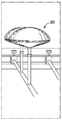
도 2는 상기한 맨드릴 딥핑 공정과 같은 공정에 의해서 쉘(30)이 처음에 형성되는, 기본적인 젤-충전 유방 이식물(28)의 예시적인 단면을 나타낸다. 외측 실리콘 엘라스토머 쉘(30)은, 이 경우에는 유방에 들어맞는, 해부학적 구조를 가지며, 쉘 홀(32)에 의해서 몰드에서 벗겨진다. 나타낸 실시 형태에서, 쉘 홀(32) 위의 패치(patch)는 홀 바로 위의 경화되지 않은 부분(34)과, 그것을 덮으며 쉘(30)의 내표면에 부착되는 경화된 부분(36)을 포함한다. 패치를 경화한 다음, 예를 들어, 패치 내의 바늘 구멍을 통해 쉘(30)의 비어있는 내부를 적당한 젤(38)로 충전한다. 실리콘 젤은 주된 젤 성분과 가교결합 성분을 갖는 2-파트 액체 시스템으로서 공급된다. 그 다음, 패치의 바늘 구멍을 실리콘 접착제 또는 플러그로 밀봉하고 이식물을 오븐 경화하여 젤의 가교결합을 달성한다.2 shows an exemplary cross-section of a basic gel-filled
기본적인 딥-몰딩 기술의 변형이 이용가능하다. 예를 들어, 스미트(Smit)의 미국 특허 출원 공개 제2004/0245671호는 외견상으로는 몰딩된 제품에 공기가 포함되지 않게 하기 위해, 몰드의 전체적인 침지 전에 위쪽 부분을 침지하도록, 아암(arm)이 몰드를 위치시키는, 유방 이식물용 실리콘 커버(쉘)을 딥 몰딩하기 위한 자동화된 시스템을 개시한다. 시스템은, 순서대로, 세정 스테이션, 딥핑 스테이션, 증발 오븐, 및 경화 오븐을 포함한다. 잡(Job)의 미국 특허 출원 공개 제2008/0208336호는 실리콘 분산물을 맨드릴 상에 스프레이하는 기술을 포함하며, 그 중 한 실시 형태는 균일하지 않은 쉘 두께를 야기한다.Variations of the basic deep-molding technique are available. For example, Smit's U.S. Patent Application Publication 2004/0245671 discloses that an arm may be immersed before the entire immersion of the mold to prevent air from being included in the molded article. Disclosed is an automated system for deep molding a silicone cover (shell) for a breast implant to position a mold. The system, in order, includes a cleaning station, a dipping station, an evaporation oven, and a curing oven. Job's US Patent Application Publication No. 2008/0208336 includes a technique of spraying a silicone dispersion onto a mandrel, one embodiment of which results in a non-uniform shell thickness.
이식물 쉘을 형성하기 위한 다른 공정은 회전 몰딩, 예를 들어, 쉬슬러(Schuessler)의 미국 특허 제6,602,452호에 기재된 시스템 및 방법이다. 이 공정도 역시 패치를 필요로 하는 홀을 갖는 유연성 이식물 쉘을 생성한다. 회전 몰딩은 딥-몰딩 또는 스프레이-몰딩에 많은 이점을 제공하지만, 후자가 최근에 산업 분야에서 더 일반적이다.Another process for forming an implant shell is a rotational molding, for example the system and method described in Schussler, US Pat. No. 6,602,452. This process also creates a flexible implant shell with holes that require patches. Rotational molding offers many advantages for dip-molding or spray-molding, but the latter is more common in the industry in recent years.
연질 보형 이식물 쉘의 구조에 있어서 많은 발전이 있었지만, 더욱 일관되게 균일한 이식물 쉘 두께를 야기하는 더 간단한 공정이 여전히 요구된다.While many advances have been made in the construction of soft prosthetic implant shells, there is still a need for simpler processes that result in more consistently uniform implant shell thicknesses.
본 발명의 특징 및 이점이 명백해질 것이며, 명세서, 특허청구범위, 및 첨부 도면을 참조하여 더욱 이해될 것이다.
도 1a 내지 도 1c는 유방 이식물 보형물의 쉘을 딥-형성하는 종래의 수동 공정의 몇 가지 단계를 나타낸다.
도 2는 전형적인 젤-충전 유방 이식물 보형물의 단면도이다.
도 3a 내지 도 3c는 본 발명의 딥- 또는 스프레이-형성 방법에 사용되는 맨드릴을 이동시키는 상이한 모드의 개략도이다.
도 4a 내지 도 4c는 분산물 커튼을 사용하는 본 발명의 쉘 형성 방법의 개략도이다.
도 5는 분산물 커튼, 및 딥핑 후드(dipping hood)를 통과하는 컨베이어 장치를 이용하여 이식물 쉘을 형성하기 위한 본 발명의 전체 시스템의 개략도이다.
도 6a 내지 도 6e는 본 발명의 예시적인 딥-몰딩 기술의 일련의 단계들의 개략도이다.
도 7은 딥-몰딩 기술을 이용하여 이식물 쉘을 형성하기 위한 본 발명의 전체 시스템의 개략도이다.
도 8은 2개의 체인 드라이브 사이에서 회전 및 운반되는 쉘-형성 맨드릴의 개략도이다.The features and advantages of the invention will be apparent and will be further understood with reference to the specification, claims, and appended drawings.
1A-1C illustrate several steps of a conventional manual process for dip-forming the shell of a breast implant implant.
2 is a cross-sectional view of a typical gel-filled breast implant implant.
3A-3C are schematic views of different modes of moving the mandrel used in the dip- or spray-forming method of the present invention.
4A-4C are schematic diagrams of a shell forming method of the present invention using dispersion curtains.
5 is a schematic diagram of the overall system of the present invention for forming an implant shell using a dispersion curtain and a conveyor device through a dipping hood.
6A-6E are schematic diagrams of a series of steps of an exemplary deep-molding technique of the present invention.
7 is a schematic diagram of the overall system of the present invention for forming an implant shell using a dip-molding technique.
8 is a schematic view of a shell-forming mandrel rotated and carried between two chain drives.
발명의 개요Summary of the Invention
본 발명은 탈휘발(devolatilization) 단계 동안 딥-맨드릴 또는 스프레이-맨드릴을 스피닝(spinning) 및 회전(rotating)시켜 균일한 커버를 보장하는 것을 포함하는, 유체-충전 보형 이식물을 위한 연질 쉘을 몰딩하기 위한 방법 및 시스템을 개시한다. 맨드릴은 딥핑 또는 스프레이 단계 동안 및/또는 나중에 용매가 증발되는 동안 검 상태가 형성될 때까지 스피닝될 수 있다. 본 기술은 연질 이식물, 예를 들어, 유방 이식물을 위해 실리콘 분산물로부터 중공 쉘을 형성하는 데 특히 유용하다.The present invention involves molding a soft shell for a fluid-filled prosthetic implant, comprising spinning and rotating a deep-mandrel or spray-mandrel during a devolatilization step to ensure a uniform cover. Disclosed are a method and system for: The mandrel may be spun until a gum condition forms during the dipping or spraying step and / or later during the solvent evaporation. The technique is particularly useful for forming hollow shells from silicone dispersions for soft implants, such as breast implants.
유방 보형물 쉘을 몰딩하기 위한, 본 명세서에 개시된 한 방법은 맨드릴 및 로드(rod) 어셈블리를 제공하는 단계를 포함하며, 로드는 제1 축을 규정하고 맨드릴은 유방 이식물 쉘의 형상이다. 실리콘 분산물을 맨드릴에 적용하고, 이를 제1 축에 대해 스피닝시킨다. 스피닝 동안, 맨드릴을 직립 위치(upright position)로부터 반대 위치로, 그리고 다시 직립 위치로 이동시킨다. 또한, 높은 탈휘발 온도에 노출되면서 실리콘 분산물이 맨드릴 상에서 고형화되는 동안 스피닝을 행한다. 스피닝은 약 5 내지 15 rpm의 속도로 행할 수 있다. 제1 축은 수평면으로부터 약 20°각도일 수 있다. 바람직하게는, 이동 단계는 맨드릴 및 로드를 수평면에 실질적으로 수직인 평면 내에서 이동시키는 것을 포함한다. 대안적으로, 적용 단계는 맨드릴을 실리콘 분산물의 커튼을 통과해 이동시키는 것, 맨드릴을 실리콘 분산물의 스프레이를 통과해 이동시키는 것, 또는 맨드릴을 실리콘 분산물에 딥핑하는 것일 수 있다.One method disclosed herein for molding a breast implant shell includes providing a mandrel and rod assembly, wherein the rod defines a first axis and the mandrel is in the shape of a breast implant shell. The silicone dispersion is applied to the mandrel, which is spun about the first axis. During spinning, the mandrel is moved from the upright position to the opposite position and back to the upright position. Spinning is also performed while the silicone dispersion solidifies on the mandrel while being exposed to high devolatilization temperatures. Spinning can be performed at a speed of about 5 to 15 rpm. The first axis may be about 20 degrees from the horizontal plane. Preferably, the moving step comprises moving the mandrel and rod in a plane substantially perpendicular to the horizontal plane. Alternatively, the applying step may be to move the mandrel through the curtain of the silicone dispersion, to move the mandrel through the spray of the silicone dispersion, or to dip the mandrel into the silicone dispersion.
연질 이식물 쉘을 몰딩하기 위한, 본 명세서에 개시된 다른 방법은 탈휘발 챔버, 복수의 맨드릴 및 긴 홀더 어셈블리(mandrel and elongated holder assembly), 운반(translation)을 위해 맨드릴 및 긴 홀더 어셈블리가 탑재되는 컨베이어, 및 실리콘 분산물 스프레이를 제공할 수 있는 스프레이 어셈블리를 포함하는 몰딩 시스템을 제공하는 단계를 포함한다. 컨베이어는 각각의 맨드릴을 그의 각각의 중심축에 대하여 스피닝시키고 각각의 맨드릴을 수직면 내에서 회전시킬 수 있는 서브시스템을 포함한다. 각각의 맨드릴은 스프레이 어셈블리의 경로(path) 내로 운반되고 실리콘 분산물 스프레이가 각각의 맨드릴에 적용되어 코팅된 맨드릴을 형성한다. 그 다음, 코팅된 맨드렐은 그의 각각의 중심축에 대해 스피닝하고 수직면 내에서 회전하는 동시에, 각각의 코팅된 맨드릴이 탈휘발 챔버로 운반된다. Another method disclosed herein for molding a soft implant shell includes a devolatilization chamber, a plurality of mandrels and elongated holder assemblies, a conveyor on which mandrels and long holder assemblies are mounted for translation. And providing a molding system comprising a spray assembly capable of providing a silicone dispersion spray. The conveyor includes a subsystem that can spin each mandrel about its respective central axis and rotate each mandrel in a vertical plane. Each mandrel is carried into the path of the spray assembly and a silicone dispersion spray is applied to each mandrel to form a coated mandrel. The coated mandrel then spins about its respective central axis and rotates in a vertical plane, while each coated mandrel is conveyed to the devolatilization chamber.
상기한 방법에서, 각각의 코팅된 맨드릴은 바람직하게는 그의 각각의 중심축에 대해 약 5 내지 15 rpm의 속도로 스피닝된다. 또한, 각각의 맨드릴은 스프레이 어셈블리의 경로에 있는 동안 그의 각각의 중심축에 대해 스피닝될 수 있다. 일 실시 형태에서, 스프레이 어셈블리는 탈휘발 챔버의 바깥쪽에 위치한다. 예를 들어, 컨베이어는 구멍(aperture)을 포함하는 탈휘발 챔버 내에 위치될 수 있으며, 그러한 구멍을 통해 각각의 맨드릴이 스프레이 어셈블리의 경로 내로 들어갈 수 있다. 스프레이 어셈블리는 맨드릴이 통과하는 분산물 커튼을 생성하는 스피곳(spigot)을 가질 수 있다. 바람직한 일 실시 형태에서, 컨베이어는 각각의 긴 홀더에 부착된 그리퍼(gripper)와 맞물리는 한 쌍의 체인 드라이브(chain drive)를 포함하며, 체인 드라이브들은 상이한 속도로 구동되어 각각의 맨드릴을 그의 중심축에 대해 스피닝시킨다. 탈휘발 챔버 내에 있는 동안 맨드릴은 그의 중심축에 대하여 연속적으로 스피닝되고 공칭 수평 배향(nominal horizontal orientation)으로부터 기울어질 수 있다.In the above method, each coated mandrel is preferably spun at a speed of about 5 to 15 rpm about its respective central axis. In addition, each mandrel may be spun about its respective central axis while in the path of the spray assembly. In one embodiment, the spray assembly is located outside of the devolatilization chamber. For example, the conveyor may be located in a devolatilization chamber that includes an aperture through which each mandrel may enter the path of the spray assembly. The spray assembly may have a spigot that creates a dispersion curtain through which the mandrel passes. In one preferred embodiment, the conveyor comprises a pair of chain drives that engage a gripper attached to each elongated holder, the chain drives being driven at different speeds to drive each mandrel to its central axis. Spin against. While in the devolatilization chamber, the mandrel can be spun continuously about its central axis and tilted from its nominal horizontal orientation.
복수의 맨드릴/로드 어셈블리;A plurality of mandrel / rod assemblies;
맨드릴/로드 어셈블리를 복수의 상이한 축에 대하여 회전시킬 수 있는 회전 어셈블리;A rotating assembly capable of rotating the mandrel / rod assembly about a plurality of different axes;
복수의 맨드릴/로드 어셈블리를 수용하는 경화 챔버;A curing chamber containing a plurality of mandrel / rod assemblies;
실리콘 분산물 스프레이를 제공할 수 있는 스프레이 어셈블리; 및A spray assembly capable of providing a silicone dispersion spray; And
각각의 맨드릴/로드 어셈블리를, 스프레이 어셈블리에 의해 제공되는 실리콘 분산물 스프레이 내로, 그리고 경화 챔버 내로 이동시킬 수 있는 드라이브 어셈블리를 포함하는, 유방 이식물 쉘을 제조하기 위한 시스템이 또한 본 명세서에 개시된다.Also disclosed herein is a system for making a breast implant shell comprising a drive assembly capable of moving each mandrel / rod assembly into a silicone dispersion spray provided by a spray assembly and into a curing chamber. .
드라이브 어셈블리는 바람직하게는 각각의 맨드릴을 그의 중심축에 대하여 스피닝시킨다. 예를 들어, 드라이브 어셈블리는 각각의 맨드릴에 부착된 그리퍼와 맞물린 2개의 체인 드라이브를 포함할 수 있으며, 체인 드라이브들은 상이한 속도로 구동되어 각각의 맨드릴을 그의 중심축에 대하여 스피닝시킨다. 체인 드라이브들의 상이한 속도는 각각의 맨드릴이 약 5 내지 15 rpm의 속도로 스피닝하도록 하는 속도이다. 마직막으로, 시스템은 로드/언로드 챔버(load/unload chamber) 및 딥핑/건조 챔버를 추가로 포함할 수 있으며, 드라이브 어셈블리는, 일렬로, 로드/언로드 챔버, 딥핑/건조 챔버, 및 경화 챔버를 포함하는 서킷(circuit) 내에서 각각의 맨드릴을 이동시킨다.The drive assembly preferably spins each mandrel about its central axis. For example, the drive assembly may include two chain drives engaged with grippers attached to each mandrel, the chain drives being driven at different speeds to spin each mandrel about its central axis. The different speed of the chain drives is the speed that allows each mandrel to spin at a speed of about 5 to 15 rpm. Finally, the system can further include a load / unload chamber and a dipping / drying chamber, and the drive assembly includes, in line, a load / unload chamber, a dipping / drying chamber, and a curing chamber. Each mandrel is moved within the circuit.
바람직한 실시 형태의 상세한 설명Detailed Description of the Preferred Embodiments
본 발명은, 균일한 벽 두께가 최종 쉘에서 제공되는 것을 신뢰성 있게 보장하지 않는, 연질의 중공 이식물 쉘을 형성하기 위한 이전의 딥- 및 스프레이-몰딩 방법에 대한 개선을 제공한다. 더욱이, 종래의 발명들 중 일부는 비교적 복잡하며, 따라서 구현하는 데 비용이 많이 든다. 본 명세서에 개시된 방법에 의해 형성되는 중공 이식물 쉘은 유체, 예를 들어, 식염수, 또는 실리콘 젤과 같은 젤의 충전이 의도된 것이다.The present invention provides an improvement over previous dip- and spray-molding methods for forming soft hollow implant shells that do not reliably ensure that uniform wall thickness is provided in the final shell. Moreover, some of the conventional inventions are relatively complex and therefore expensive to implement. Hollow implant shells formed by the methods disclosed herein are intended to be filled with fluids, eg, saline, or gels such as silicone gels.
유체-충전 연질 이식물을 위한 한 가지 응용은 여성의 유방을 재건 또는 확대하는 것이다. 다른 가능한 응용은 다른 부위들 중에서도, 턱끝, 엉덩이, 고환, 또는 종아리를 위한 이식물이다. 더욱이, 본 발명은 유방 이식물을 위해 특히 유리하며, 위내 풍선(intragastric balloon) 및 다른 이식물이 본 명세서에 기재된 방법에 의해 형성될 수 있다. 또한, 자체로는 이식물로 보이지 않을 수 있는 조직 확장기가 또한 본 명세서에 개시된 개념으로부터 이득을 얻을 수 있다. 그러한 경우, 본 명세서에서 사용되는 바와 같은 이식물이라는 용어는 장기간 및 단기간 이식되는 장치를 지칭한다.One application for fluid-filled soft implants is to rebuild or enlarge a woman's breast. Another possible application is an implant for the tip, hip, testicle, or calf, among other sites. Moreover, the present invention is particularly advantageous for breast implants, where intragastric balloons and other implants can be formed by the methods described herein. In addition, tissue expanders, which may not appear as implants themselves, may also benefit from the concepts disclosed herein. In such cases, the term implant as used herein refers to a device that is implanted long and short term.
본 발명의 방법은 연조직 이식물을 위한 쉘을 생성하는 데 사용되는 통상적인 딥 및 스프레이-몰딩 기술을 개선한다. 실리콘 분산물이 맨드릴로부터 배수될 때 실리콘 분산물의 흐름은 맨드릴의 형상 및 배향에 따라 좌우되기 때문에, 맨드릴의 배향이 고정된 채로 유지되는 경우, 생성되는 쉘은 그 두께가 실질적으로 다양할 수 있다. 예를 들어, 고정식 맨드릴 상에서 통상적인 딥 캐스팅에 의해 형성되는 유방 이식물 쉘의 두께는 영역에 따라 0.009 내지 0.024 인치로 다양할 수 있으며, 편차는 100%를 초과한다. 중요한 것은, 쉘의 다양한 영역의 두께가 맨드릴의 형상 및 실리콘 분산물이 맨드릴로부터 배수되는 기간 동안의 맨드릴의 배향에 의해 대부분 영향을 받는다는 것이다.The method of the present invention improves on conventional dip and spray-molding techniques used to create shells for soft tissue implants. Since the flow of the silicone dispersion depends on the shape and orientation of the mandrel when the silicone dispersion is drained from the mandrel, if the orientation of the mandrel remains fixed, the resulting shell may vary substantially in thickness. For example, the thickness of a breast implant shell formed by conventional deep casting on a stationary mandrel may vary from 0.009 to 0.024 inches depending on the area, with deviations exceeding 100%. Importantly, the thickness of the various regions of the shell is largely affected by the shape of the mandrel and the orientation of the mandrel during the period that the silicone dispersion is drained from the mandrel.
딥 몰딩에서, 딥 몰딩에서, 맨드릴은 쉘의 앞쪽 면에 상응하는 부분이 아래로 향하도록 유지된다. 맨드릴을 유지하는 데 사용되는 브래킷(bracket) 또는 로드는, 분산물 내로 딥핑될 때, 맨드릴 공정에 대한 도 1b에 나타낸 바와 같이, 쉘의 뒷쪽 면에 상응하는 맨드릴의 부분으로부터 바깥쪽으로 연장된다. 분산물은 맨드릴의 외주(perimeter) 영역으로부터 상대적으로 신속하게 배수되며, 그 결과로 외주 영역의 쉘은 극(polar) 영역의 쉘보다 더 얇은 경향이 있다. 이러한 이유로, 외주 영역에 알맞은 쉘 두께를 생성하기 위해서는 추가적인 딥이 필요하다. 이는 극 영역에서, 특히 앞쪽 면에서 필요한 것보다 더 두꺼운 쉘을 야기할 수 있다. 스프레이 몰딩의 경우, 더 얇은 적용으로 인해, 정도는 더 작지만 동일한 문제가 발생한다.In deep molding, in deep molding, the mandrel is maintained with the portion corresponding to the front face of the shell facing down. The bracket or rod used to hold the mandrel extends outward from the portion of the mandrel corresponding to the back side of the shell, as shown in FIG. 1B for the mandrel process, when dipped into the dispersion. The dispersion drains relatively quickly from the perimeter region of the mandrel, with the result that the shell of the outer region tends to be thinner than the shell of the polar region. For this reason, additional dips are needed to create shell thicknesses that are suitable for the outer region. This can lead to shells thicker than necessary in the polar region, especially in the front face. In the case of spray moldings, due to the thinner application, the degree is smaller but the same problem arises.
본 출원은 맨드릴이 실리콘 분산물에 침지된 후, 맨드릴을 하나 이상의 상이한 축에 대하여 회전시켜, 다양한 스피닝 동작으로부터 얻어지는 원심력을 이용하여 분산물이 맨드릴 표면 전반에 균일하게 퍼지도록 하는 기계 장비를 기술한다. 더욱 구체적으로, 바람직한 방법은 맨드릴을 그 자체의 축에 대해 스피닝시키는 동시에, 맨드릴을 하나 이상의 다른 축에 대하여 회전시키는 것이다. The present application describes a mechanical device that after a mandrel is immersed in a silicone dispersion, the mandrel is rotated about one or more different axes so that the dispersion is spread evenly across the mandrel surface using centrifugal forces resulting from various spinning operations. . More specifically, the preferred method is to spin the mandrel about its own axis while rotating the mandrel about one or more other axes.
일 실시 형태에서, 실리콘은 자일렌과 같은 용매 내의 분산물로서 제공된다. 유방 이식물 쉘을 형성하기 위한 기본적인 제조 공정은 맨드릴을 경화되지 않은 실리콘 분산물에 코팅하는 단계, 용매를 제거하는 단계(탈휘발), 및 이어서 재료를 경화시켜 엘라스토머로 변환시키는 단계를 수반한다. 적어도 불균일한 두께의 측면에서, 대부분의 제조상 문제점이 발생하는 것은 용매 제거 단계 동안이다.In one embodiment, the silicone is provided as a dispersion in a solvent such as xylene. The basic manufacturing process for forming the breast implant shell involves coating the mandrel on the uncured silicone dispersion, removing the solvent (volatiles), and then curing the material to convert it into an elastomer. At least in terms of non-uniform thickness, most of the manufacturing problems arise during the solvent removal step.
종래 기술의 방법에 따르면, 열-경화 실리콘의 맥락에서, 맨드릴을 실리콘 분산물에 침지한 다음에, 온도가 다소 높여진 챔버 (전형적으로 35℃ 내지 60℃)에 넣어서 용매를 증발시키고, 재료는 "검" 상태로 남게 된다. 이 공정 동안, 맨드릴은 정지한 직립 위치에서 유지된다. 재료가 유체 상태이기 때문에, 중력으로 인해 상당한 양이 맨드릴로부터 흘러내려서 많은 폐기물을 생성하며, 남아있는 재료 층은 불균일한 두께를 갖는다. 원하는 벽 두께를 달성하기 위해서는 다회의 침지가 흔히 필요하다. 다회의 침지 및 탈휘발 단계 후에, 맨드릴은 재료를 검 상태로부터 가교결합된 엘라스토머 상태로 변환시키는 경화 공정에 제공된다.According to the prior art methods, in the context of heat-curing silicone, the mandrel is immersed in the silicone dispersion, and then placed in a slightly elevated chamber (typically from 35 ° C. to 60 ° C.) to evaporate the solvent and the material It remains in the "sword" state. During this process, the mandrel is held in a stationary upright position. Because the material is in a fluid state, gravity causes a significant amount to flow out of the mandrel, creating a lot of waste, and the remaining material layers have non-uniform thicknesses. Multiple dipping is often required to achieve the desired wall thickness. After multiple immersion and devolatilization steps, the mandrel is subjected to a curing process that converts the material from the gum state to the crosslinked elastomeric state.
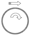
본 발명은 종래 기술에서 겪게 되는 문제점의 적어도 일부를 극복한 공정을 제공한다. 일 실시 형태에 따르면, 맨드릴(40)은 로드(42) 또는 다른 그러한 긴 경질 홀더(elongated rigid holder) 상에 지지된다. 맨드릴 또는 로드는, a) 맨드릴 및/또는 로드를 수평면으로부터 회전시킬 수 있고/있거나, b) 맨드릴 및/또는 로드를 수직면으로부터 회전시킬 수 있고/있거나, c) 맨드릴을 로드의 중심축에 대하여 스피닝시킬 수 있고/있거나, d) 맨드릴을 공정 장비 주위로 운반할 수 있는 적합한 기계 장비에 의해서 조종된다. 로드의 중심축은 전형적으로, 생성되는 이식물 쉘이 선대칭(axisymmetric)이 되는 축을 규정하는 맨드릴의 중심축과 일치한다는 것에 주의해야만 한다. 이러한 가능한 운동 3가지가 도 3a 내지 3c에 나타나있다. 예를 들어, 맨드릴(40)은 제1 축(x)에 대하여 수직면 내에서 회전하여 직립 위치로부터 수평면을 통과해 완전히 반대 위치로 180°이동할 수 있다. 또한, 맨드릴은 공정 장비 둘레에서 제2 축(y)를 따라 운반될 수 있다. 또한, 맨드릴은 제3 축(z)에 대하여 로드를 따라 스피닝할 수 있다.The present invention provides a process that overcomes at least some of the problems encountered in the prior art. According to one embodiment, the
본 발명의 일부 실시형태에서는, 로드에 대하여 회전하는 것이 맨드릴이지만, 다른 실시 형태에서는, 맨드릴 및 로드가 회전하며, 이는 움직이는 부분과 딥핑 탱크 또는 스프레이 헤드 사이의 일부 분리를 제공한다. 또한, 다양한 조합, 속도, 운동들 사이의 순서 및 일시정지가 고려된다. 소정 예시적인 공정 단계가 하기에 기술되지만, 제한하는 것으로 여겨져서는 안 되며, 본 출원은 균일한 쉘 두께를 야기하는 다양한 특정 단계들을 포괄한다. 마지막으로, 당업자에게 명백한 바와 같이, 가장 일반적인 목적은 균일한 두께가 되게 하는 것이지만, 맨드릴에 부가되는 소정 운동에 의해서 쉘의 영역들이 더 두껍게 만들어질 수 있음이 이해되어야 한다.In some embodiments of the present invention, it is the mandrel that rotates with respect to the rod, but in other embodiments, the mandrel and the rod rotate, which provides some separation between the moving portion and the dipping tank or spray head. Also, various combinations, speeds, sequences and pauses between exercises are considered. Certain exemplary process steps are described below, but should not be considered limiting, and the present application encompasses a variety of specific steps that result in uniform shell thickness. Finally, as will be apparent to one skilled in the art, the most common purpose is to have a uniform thickness, but it should be understood that areas of the shell can be made thicker by some movement added to the mandrel.
도 4a 내지 도 4c는 분산물 커튼 흐름을 사용하는 예시적인 공정에서의 몇 가지 단계를 나타낸다. 도 4a에 나타낸 바와 같이, 맨드릴(40)은 스피곳(52)으로부터 나오는 분산물 스트림 또는 커튼(50)으로 들어가기 직전에 예를 들어, 5 내지 15 rpm으로 로드 축에 대하여 회전하기 시작한다. 도시된 분산물 스트림 커튼(50)은 분산물의 스프레이를 나타내거나 그의 대체물일 수 있으며, 스프레이 및 커튼이라는 용어는 (고정식 딥핑 탱크와는 대조적으로) 맨드릴 상으로 또는 그 위로 향하는 분산물의 흐름을 정의한다는 점에서 실질적으로 같은 의미이다.4A-4C illustrate several steps in an exemplary process using dispersion curtain flow. As shown in FIG. 4A, the
그 다음, 맨드릴(40)은 도 4b에 나타낸 바와 같이 로드 축에 대하여 계속 회전하면서 분산물 커튼(50)을 통과해 이동한다(예를 들어, 약 2 m/min). 맨드릴은 적어도 360°의 맨드릴 회전 동안 분산물 커튼이 그의 상부 모면(generatrix) 상으로 떨어지도록 충분히 천천히 이동한다. 여분의 분산물은 분산물 재료의 재활용을 위한 하부의 수집 대야(collection basin)(54)로 떨어진다. 맨드릴은 수집 대야 위에 있는 동안 더 이상의 여분이 똑똑 떨어지지 않을 때까지 계속해서 회전 및 일시정지할 수 있다. 분산물 커튼을 통과한 후에, 도 4c에서와 같이, 맨드릴은 용매, 전형적으로 자일렌을 증발 및 제거하는 데 도움이 되도록 높은 탈휘발 온도에 노출된다. 건조 사이클 동안 맨드릴을 연속적으로 회전시킴으로써 분산물 폐기물 또는 드립(drip)이 없도록 추가로 보장한다. 쉘은 전형적으로 회전축에 수직인 중심 평면에서 가장 두꺼울 것이다.The
일부 실시 형태에서, 가열 없이 탈휘발이 또한 일어날 수 있음을 나타내기 위해 증발 오븐을 도시하지 않은 도 4c에 나타낸 바와 같이, 탈휘발 동안 맨드릴은 로드 축에 대하여 스피닝을 계속한다. 스피닝 운동은 로드 축에 대하여 원심력을 생성하여 분산물을 맨드릴 표면 상에 효과적으로 유지하고, 재료가 흘러내리는 것을 방지하며 분산물 층을 고르게 해준다. 이는 재료 폐기물을 제거하고 두꺼운 부분과 얇은 부분이 고르게 되기 때문에 각각의 통과에 대해 최대 두께가 형성되게 해준다. 즉, 맨드릴에 부착되는 일정 부피의 재료가 표면적을 효과적으로 커버하고, 가장 얇은 지역인 (그리고 따라서 동시에 가장 두꺼운 지역인) 제한 요인이 맨드릴 주위로 연장된다.In some embodiments, the mandrel continues spinning about the rod axis during devolatilization, as shown in FIG. 4C, which does not show an evaporation oven to indicate that devolatilization may also occur without heating. Spinning motion creates centrifugal forces with respect to the rod axis to effectively maintain the dispersion on the mandrel surface, prevent material from flowing down and even the dispersion layer. This eliminates material waste and allows thick and thin sections to be even, allowing for maximum thickness to be formed for each pass. That is, a volume of material attached to the mandrel effectively covers the surface area, and the limiting factor, which is the thinnest area (and therefore the thickest area at the same time), extends around the mandrel.
회전 속도는 분산물 재료의 리올로지(rheology) 특성 및 맨드릴 표면과 분산물 사이의 표면장력에 따라 좌우될 것이다. 예를 들어, 더 큰 점도를 갖는 (더 진한) 분산물은 덜 점성인 (흐린) 것만큼 쉽게 맨드릴로부터 똑똑 떨어지지 않을 것이며, 결과적으로 그 만큼 빠른 맨드릴 회전이 필요하지 않을 것이다. 마찬가지로, 분산물과 맨드릴 표면 (또는 분산물과 먼저 형성된 층) 둘 모두의 특성이 회전 속도에 영향을 줄 것이다. 둘 사이의 표면장력이 큰 경우라면, 분산물이 맨드릴로부터 똑똑 떨어질 가능성이 작을 것이며 표면 장력이 더 작은 경우보다 더 느린 회전 속도가 이용될 수 있다.The speed of rotation will depend on the rheology properties of the dispersion material and the surface tension between the mandrel surface and the dispersion. For example, (dense) dispersions with higher viscosities will not drip off the mandrel as easily as less viscous (cloudy) and consequently no faster mandrel rotation is needed. Likewise, the properties of both the dispersion and the mandrel surface (or the layer formed first with the dispersion) will affect the speed of rotation. If the surface tension between the two is large, it is unlikely that the dispersion will drip off the mandrel and slower rotational speeds may be used than if the surface tension is smaller.
예를 들어, 낮은 리올로지 특성을 갖는 점도가 600 cP인 분산물의 경우 많은 분산물이 흘러내려서 얇은 쉘을 생성하고 높은 리올로지 특성을 갖는 것은 분산물 흐름이 불량하고 쉘의 두꺼운 영역이 국지화된다는 것이 본 발명자들에 의해 밝혀졌다. 지역에서의 약 10 rpm의 회전 속도는 충분한 원심 에너지를 생성하여 (맨드릴 형상에 관계없이) 높은 리올로지의 실리콘 분산물을 맨드릴 주위로 균일하게 퍼지게 하지만, 또한 낮은 리올로지의 실리콘 분산물이 맨드릴로부터 떨어져 나가지 않도록 하기에 충분히 낮은 속도이다.For example, for dispersions with a low rheological property of viscosity of 600 cP, many dispersions flow down to produce thin shells and high rheological properties indicate poor dispersion flow and localized thick areas of the shells. It was discovered by the inventors. Rotational speeds of about 10 rpm in the region produce sufficient centrifugal energy to uniformly spread the high rheological silicone dispersion around the mandrel (regardless of the mandrel shape), but also the low rheological silicone dispersion from the mandrel It's low enough to keep it from falling off.
예를 들어, 일 실시 형태에서, 점도가 약 600 센티푸아즈인 실리콘 분산물의 경우 맨드릴은 적어도 약 10 rpm의 속도로 회전된다. 둥근 대칭형 맨드릴의 경우, 수평에 대해 약 0°의 회전각이 실질적으로 균일한 두께을 제공할 것이다. 형상화된 (예를 들어, 해부학적으로 형상화된) 맨드릴은 약 +20°내지 약 -20°의 회전각으로 위치될 수 있다. 국지화된 두께가 요구되는 경우, 회전을 늦추면서 맨드렐을 적당한 각도로 유지할 수 있다.For example, in one embodiment, for a silicone dispersion having a viscosity of about 600 centipoise, the mandrel is rotated at a speed of at least about 10 rpm. For a round symmetrical mandrel, an angle of rotation of about 0 ° relative to the horizontal will provide a substantially uniform thickness. The shaped (eg, anatomically shaped) mandrel may be positioned at a rotation angle of about + 20 ° to about -20 °. If localized thickness is desired, the mandrel can be held at an appropriate angle while slowing down the rotation.
더욱이, 맨드릴 형상이 맨드릴 배향뿐만 아니라 디자인 회전 속도에 영향을 줄 수 있다. 예를 들어, 유방 이식물 쉘은 측면으로부터의 계란형 프로파일, 또는 더욱 자연스럽게는 눈물방울 형상을 갖도록 형성될 수 있다. 전자의 경우, 쉘은 적어도 하나의 축에 대해 대칭일 것이며, 이는 맨드릴의 스피닝 속도 및 각운동에 영향을 줄 것이다. 후자의 경우, 윤곽을 이루는 형상에 맞도록 맨드릴의 스피닝 속도 및 각운동이 변경될 것이다. 또한, 분산물이 전체 맨드릴 표면을 더욱 균일하게 커버하거나, 또는 한 지역 또는 다른 지역에서 축적되게 하기 위해 일정 기간 동안 맨드릴이 수평에 대해 상이한 각도에서 유지될 수 있다.Moreover, the mandrel shape can affect the design rotation speed as well as the mandrel orientation. For example, the breast implant shell can be formed to have an oval profile from the side, or more naturally, a teardrop shape. In the former case, the shell will be symmetric about at least one axis, which will affect the spinning speed and the angular motion of the mandrel. In the latter case, the spinning speed and angular motion of the mandrel will be altered to fit the contouring shape. In addition, the mandrel may be held at different angles to the horizontal for a period of time to allow the dispersion to cover the entire mandrel surface more evenly, or to accumulate in one area or another.
도 5는 분산물 커튼 기술이 사용된, 본 발명에 따른 전체 시스템을 나타낸다. 복수의 맨드릴(60)이 운반 또는 총체적인 회전을 위해, 동일하거나 상이한 속도로 구동될 수 있는 2개의 체인(62, 64)를 갖는 것으로 도시된, 컨베이어 또는 체인 드라이브 시스템 상에 탑재된다. 체인 드라이브 시스템은 가열이 있거나 없이 탈휘발이 일어날 수 있는 공간을 제공하는 딥핑 후드(66) 내에 위치하는 것으로 도시된다. 딥핑 후드 바깥의 외부 드라이브 모터(68)는 체인 드라이브를 구동시킨다. 각각의 맨드릴(60)은 (좌측에 도시된 구멍(70)을 통과하여) 주기적으로 딥핑 후드를 빠져나가서 스피곳(74)으로부터 나오는 분산물 커튼(72)을 통과한다. 다시 한번, 수집 대야(76)가 흘러내리는 것을 받아서 분산물 재료의 재활용을 위해 제공한다. 따라서, 맨드릴은 분산물의 순차적인 층으로 연속하여 코팅된다. 다른 코트를 기다리는 동안, 적어도 일부의 용매를 마지막으로 적용된 층으로부터 증발시키기에 충분한, 바람직하게는 분산물의 검 상태를 형성하기에 충분한 기간 동안, 맨드릴이 딥핑 후드를 통해 운반된다. 증발 공정 동안, 맨드릴은 그의 축에 대하여 연속적으로 스피닝될 수 있을 뿐만 아니라, 공칭 수평 배향으로부터 기울어질 수 있다.5 shows an overall system according to the present invention in which dispersion curtain technology is used. A plurality of
도 6a 내지 도 6e는 본 발명에 따른 딥-몰딩 공정의 단계들을 개략적으로 나타낸다. 맨드릴은 도 6a에 나타낸 바와 같이 로드 축 상의 스피닝뿐만 아니라 운반 및 잠재적으로 다른 각운동을 시작한다. 도 6b는 분산물 조를 갖는 용기 위에서 일시정지하는 맨드릴을 나타낸다. 도 6c는 수평으로부터 맨드릴이 아래쪽을 향하는 배향으로 90°반전되는 맨드릴을 나타내며, 도 6d는 분산물 조에 딥핑되었다가 나오는 맨드릴을 나타낸다. 맨드릴이 분산물 조로부터 위로 빠져나오기 시작할 때, 맨드릴은 로드 축에 대하여 스피닝하기 시작하고 선택적으로 특정 맨드릴 형상에 적합하게, 수평에 대해 일정 각도를 취한다. 마지막으로, 도 6e는 수평 (또는 각을 이룬) 배향이며, 분산물 조로부터 꺼내지고, 회전을 계속하면서 탈휘발 챔버로 운반되는 맨드릴을 나타낸다. 그 다음, 맨드릴은 로드 축에 대하여 계속해서 회전하면서 용매 제거를 위하여 높은 탈휘발 온도에 노출된다. 6A-6E schematically illustrate the steps of a dip-molding process according to the present invention. The mandrel starts the spinning and potentially other angular motion as well as spinning on the rod axis as shown in FIG. 6A. 6B shows the mandrel pausing over a vessel having a dispersion bath. FIG. 6C shows the mandrel inverted 90 ° from horizontal to the downwardly oriented mandrel, and FIG. 6D shows the mandrel coming out of the dispersion bath. As the mandrel begins to emerge up out of the dispersion bath, the mandrel begins to spin about the rod axis and optionally takes an angle to the horizontal, to suit the particular mandrel shape. Finally, FIG. 6E shows the mandrel in a horizontal (or angled) orientation, taken out of the dispersion bath and transported to the devolatilization chamber while continuing to rotate. The mandrel is then exposed to high devolatilization temperatures for solvent removal while continuing to rotate about the rod axis.
도 7은 본 발명의 실시 형태에 따른 전체 시스템의 더 큰 도면으로, 분산물 조(80)가 아래쪽 중간에 도시된다. 맨드릴이 이동하는 서킷은 딥핑/건조 섹션 또는 챔버(84)로 들어가기 전에 먼저 로드/언로드 섹션 또는 챔버(82)를 포함한다. 건조 동안, 맨드릴은 연속적으로 또는 주기적으로 그의 축에 대해 스피닝되는 동시에, 역시 아마도 맨드릴 형상 및/또는 표면장력에 따라 선택적으로 다른 방향으로 기울어진다. 맨드릴은 위쪽으로 이동한 다음 탈휘발 및 경화 섹션 또는 챔버(86)를 통해 왼쪽으로 이동한다. 상기에 설명한 바와 같이, 분산물의 검 상태를 형성하기에 충분한 용매의 증발 전에, 맨드릴은 바람직하게는 연속적으로 스피닝되어 균일한 두께를 보장한다. 마지막으로, 맨드릴은 다시 로드/언로드 챔버(82)로 내려오고, 동일하거나 상이한 분산물의 적용을 위해 그로부터 다시 딥핑/건조 챔버(84)로 들어갈 수 있거나, 또는 마지막 층이 적용되었다면 공정이 중단될 수 있다.FIG. 7 is a larger view of the overall system according to an embodiment of the present invention, with
도 8은 본 명세서에 기재된 몇몇 시스템 둘레로 맨드릴을 운반하기 위한 체인 드라이브의 가능한 구현예를 나타낸다. X1 m/min의 속도로 이동하는 체인 A는 (예를 들어, 외부 톱니(cog)를 통해), 맨드릴 로드(92)에 장착되어 함께 회전하는 그리퍼(90)의 위쪽에 작용한다. X2 m/min의 속도로 이동하는 체인 B는 그리퍼(90)의 아래쪽에 작용한다. 맨드릴의 전체적인 운반 방향은 예를 들어, 약 2 m/min의 속도로 오른쪽으로 운반되는 것이며, 속도 X1>X2이므로 맨드릴이 로드/그리퍼 축에 대하여 시계 방향으로 예를 들어, 약 5 내지 15 rpm의 속력으로 스피닝한다. 전체 체인 드라이브 시스템은 맨드릴을 수평에 대해 일정 각도들로 기울여 재위치시킬 수 있거나, 또는 각각의 맨드릴 로드 내의 또는 그와 연결된 매커니즘이 이용될 수 있다.8 shows a possible implementation of the chain drive for transporting the mandrel around some of the systems described herein. Chain A, moving at a speed of X 1 m / min (eg, via an external cog), is mounted on the
본 발명을 소정 정도로 구체적으로 기재 및 예시하였으나, 본 설명은 단지 예시의 방식으로 이루어진 것이며, 부분들의 조합 및 배열에 따른 수많은 변형이 하기에 청구된 바와 같은 본 발명의 범주를 벗어남이 없이 당업자에게 고려될 수 있다.Although the present invention has been described and illustrated to some extent in detail, the description has been made by way of example only, and numerous modifications in combination and arrangement of parts are contemplated by those skilled in the art without departing from the scope of the invention as claimed below. Can be.
Claims (20)
맨드릴 및 로드 어셈블리를 제공하는 단계 - 로드는 제1 축을 규정하고 맨드릴은 유방 이식물 쉘의 형상임 -;
실리콘 분산물을 맨드릴에 적용하는 단계;
맨드릴을 제1 축에 대하여 스피닝(spinning)시키는 단계; 및
맨드릴이 제1 축에 대하여 스피닝되는 동안, 맨드릴을 직립 (upright) 위치로부터 반대 위치로, 그리고 다시 직립 위치로 이동시키는 단계를 포함하며;
실리콘 분산물이 맨드릴 상에서 고형화되는 동안 스피닝이 수행되는 방법.As a method for molding a breast implant shell,
Providing a mandrel and rod assembly, wherein the rod defines a first axis and the mandrel is in the shape of a breast implant shell;
Applying the silicone dispersion to the mandrel;
Spinning the mandrel about a first axis; And
Moving the mandrel from an upright position and back to an upright position while the mandrel is spinning about the first axis;
Spinning is performed while the silicone dispersion solidifies on the mandrel.
탈휘발(devolatilization) 챔버;
복수의 맨드릴 및 긴 홀더 어셈블리(mandrel and elongated holder assembly);
운반을 위해 맨드릴 및 긴 홀더 어셈블리가 탑재되는 컨베이어 - 컨베이어는 각각의 맨드릴을 그의 각각의 중심축에 대해 스피닝시킬 수 있으며 각각의 맨드릴을 수직면 내에서 회전(rotating)시킬 수 있는 서브시스템을 포함함 - ;
실리콘 분산물 스프레이를 제공할 수 있는 스프레이 어셈블리를 포함하는 몰딩 시스템을 제공하는 단계;
각각의 맨드릴을 스프레이 어셈블리의 경로(path) 내로 운반하고 실리콘 분산물 스프레이를 각각의 맨드릴에 적용하여 코팅된 맨드릴을 형성하는 단계 ; 및
코팅된 맨드릴을 그의 각각의 중심축에 대하여 스피닝시키고 코팅된 맨드릴을 수직면 내에서 회전시키면서 각각의 코팅된 맨드릴을 탈휘발 챔버 내로 운반하는 단계를 포함하는 방법.A method of molding a soft implant shell,
Devolatilization chamber;
A plurality of mandrel and elongated holder assemblies;
Conveyor mounted with mandrel and long holder assembly for transport, the conveyor includes a subsystem capable of spinning each mandrel about its respective central axis and rotating each mandrel in a vertical plane ;
Providing a molding system comprising a spray assembly capable of providing a silicone dispersion spray;
Conveying each mandrel into the path of the spray assembly and applying a silicone dispersion spray to each mandrel to form a coated mandrel; And
Spinning the coated mandrel about its respective central axis and conveying each coated mandrel into the devolatilization chamber while rotating the coated mandrel in a vertical plane.
복수의 맨드릴/로드 어셈블리;
맨드릴/로드 어셈블리를 복수의 상이한 축에 대하여 회전시킬 수 있는 회전 어셈블리;
복수의 맨드릴/로드 어셈블리를 포함하는 경화 챔버;
실리콘 분산물 스프레이를 제공할 수 있는 스프레이 어셈블리; 및
각각의 맨드릴/로드 어셈블리를 스프레이 어셈블리에 의해 제공되는 실리콘 분산물 스프레이 내로, 그리고 경화 챔버 내로 이동시킬 수 있는 드라이브 어셈블리를 포함하는 시스템.A system for making a breast implant shell,
A plurality of mandrel / rod assemblies;
A rotating assembly capable of rotating the mandrel / rod assembly about a plurality of different axes;
A cure chamber comprising a plurality of mandrel / rod assemblies;
A spray assembly capable of providing a silicone dispersion spray; And
A system comprising a drive assembly capable of moving each mandrel / rod assembly into a silicone dispersion spray provided by the spray assembly and into a curing chamber.
Applications Claiming Priority (2)
| Application Number | Priority Date | Filing Date | Title |
|---|---|---|---|
| US11640608P | 2008-11-20 | 2008-11-20 | |
| US61/116,406 | 2008-11-20 |
Publications (1)
| Publication Number | Publication Date |
|---|---|
| KR20110103964A true KR20110103964A (en) | 2011-09-21 |
Family
ID=42133787
Family Applications (1)
| Application Number | Title | Priority Date | Filing Date |
|---|---|---|---|
| KR1020117014140A Withdrawn KR20110103964A (en) | 2008-11-20 | 2009-11-19 | Systems and methods for molding soft fluid-filled implant shells |
Country Status (11)
| Country | Link |
|---|---|
| US (3) | US8431179B2 (en) |
| EP (2) | EP2379298B1 (en) |
| KR (1) | KR20110103964A (en) |
| CN (1) | CN102256762A (en) |
| AR (1) | AR075357A1 (en) |
| AU (1) | AU2009316547A1 (en) |
| BR (1) | BRPI0921104A2 (en) |
| CA (1) | CA2744062A1 (en) |
| ES (1) | ES2397688T3 (en) |
| RU (1) | RU2011124178A (en) |
| WO (1) | WO2010059834A2 (en) |
Cited By (2)
| Publication number | Priority date | Publication date | Assignee | Title |
|---|---|---|---|---|
| WO2022182024A1 (en) * | 2021-02-25 | 2022-09-01 | 오스템임플란트 주식회사 | Method for manufacturing breast implant |
| WO2022182039A1 (en) * | 2021-02-25 | 2022-09-01 | 오스템임플란트 주식회사 | Method for manufacturing artificial breast prosthesis |
Families Citing this family (19)
| Publication number | Priority date | Publication date | Assignee | Title |
|---|---|---|---|---|
| EP2333521B1 (en) | 2001-04-30 | 2019-12-04 | The General Hospital Corporation | Method and apparatus for improving image clarity and sensitivity in optical coherence tomography using dynamic feedback to control focal properties and coherence gating |
| KR20110103964A (en) * | 2008-11-20 | 2011-09-21 | 알러간, 인코포레이티드 | Systems and methods for molding soft fluid-filled implant shells |
| EP2605732B1 (en) | 2010-08-18 | 2018-02-14 | Christopher Burnside Gordon | In situ molded orthotic and method for its fabrication |
| KR20120032392A (en) * | 2010-09-28 | 2012-04-05 | 유원석 | Silicon implant manufacturing method with improved durability shell |
| WO2012162642A2 (en) * | 2011-05-26 | 2012-11-29 | Advenira Enterprises, Inc. | System and process for coating an object |
| US10022842B2 (en) | 2012-04-02 | 2018-07-17 | Thomas West, Inc. | Method and systems to control optical transmissivity of a polish pad material |
| SG11201406287QA (en) | 2012-04-02 | 2014-11-27 | Thomas West Inc | Methods and systems for centrifugal casting of polymer polish pads and polishing pads made by the methods |
| US10722997B2 (en) * | 2012-04-02 | 2020-07-28 | Thomas West, Inc. | Multilayer polishing pads made by the methods for centrifugal casting of polymer polish pads |
| US10820984B2 (en) | 2012-11-14 | 2020-11-03 | ImplantADJUST, LLC | Implant with elastomeric membrane and methods of fabrication thereof |
| US9351824B2 (en) | 2012-11-14 | 2016-05-31 | ImplantADJUST, LLC | Adjustable implant with self-sealing elastomeric membrane and methods of fabrication thereof |
| CA2895083A1 (en) * | 2012-12-13 | 2014-06-19 | Allergan, Inc. | Device and method for making a variable surface breast implant |
| ITPI20130015A1 (en) * | 2013-03-07 | 2014-09-08 | S M Scienzia Machinale S R L | EQUIPMENT AND METHOD FOR THE PRODUCTION OF A BIO-COMPATIBLE THREE-DIMENSIONAL OBJECT |
| US20160052178A1 (en) * | 2014-08-21 | 2016-02-25 | Applied Silicone Corporation | Automated prosthesis shell system and method |
| US20160130690A1 (en) * | 2014-11-12 | 2016-05-12 | Applied Silicone Corporation | Immersion Curing Process |
| EP3347182B1 (en) | 2015-09-11 | 2022-07-13 | S.M. Scienzia Machinale S.r.l | Apparatus and method for producing a biocompatible three-dimensional object |
| BR112021004515A2 (en) | 2018-09-10 | 2021-06-08 | ImplantADJUST, LLC | elastomeric membrane implant and related manufacturing methods |
| WO2020214328A2 (en) * | 2019-03-19 | 2020-10-22 | University Of Pittsburgh - Of The Commonwealth System Of Higher Education | Automation mechanism for pre/clinical production of resorbable nerve guides |
| US11357614B1 (en) | 2021-06-11 | 2022-06-14 | Marcel Malek | Breast implant |
| CN116492119A (en) * | 2022-09-21 | 2023-07-28 | 陕西麦克斯韦医疗科技有限公司 | Breast milk processing system |
Family Cites Families (78)
| Publication number | Priority date | Publication date | Assignee | Title |
|---|---|---|---|---|
| US2128827A (en) * | 1938-03-09 | 1938-08-30 | Frank B Killian | Method and apparatus for manufacturing thin rubber articles |
| US2469892A (en) * | 1947-09-10 | 1949-05-10 | Rempel Entpr | Hollow article and method and apparatus for producing the same |
| GB702146A (en) | 1950-11-10 | 1954-01-13 | Chad Valley Company Ltd | A new or improved process for the production of dolls and other toys |
| US2804643A (en) * | 1955-03-21 | 1957-09-03 | Theodore A Miller | Vacuum extractor apparatus for removing hollow flexible molded articles from reentrant mold cavities |
| US3652748A (en) * | 1965-05-14 | 1972-03-28 | Arthur H Roberts | Process for preparing molded hollow articles |
| US3439079A (en) * | 1966-05-16 | 1969-04-15 | Gen Electric | Molding hollow articles |
| GB1192360A (en) | 1966-09-28 | 1970-05-20 | Courtaulds Ltd | The Centrifugal Casting of Rollers |
| GB1206110A (en) | 1966-12-19 | 1970-09-23 | Courtaulds Ltd | Cast wheels |
| US4043721A (en) * | 1968-07-11 | 1977-08-23 | Lemelson Jerome H | Composite body molding apparatus |
| GB1306541A (en) | 1969-01-20 | 1973-02-14 | Ceskoslovenska Akademie Ved | Method of manufacturing tubes by centrifugal casting |
| US3652368A (en) * | 1969-12-17 | 1972-03-28 | Plastics Inc | Apparatus for rotational molding of laminated hollow structures |
| US3584105A (en) * | 1970-01-14 | 1971-06-08 | Pekor Iron Works | Method of centrifugally forming hollow articles |
| BE757080A (en) | 1970-04-03 | 1971-03-16 | Giehler Herbert | PROCESS AND DEVICE FOR THE MANUFACTURING OF HOLLOW PARTS OF HERMOPLASTIC MATERIAL BY ROTATIONAL MOLDING IN MELTED STATE |
| US3683062A (en) * | 1970-08-20 | 1972-08-08 | Essex International Inc | Rotational casting method |
| US3788382A (en) * | 1970-11-25 | 1974-01-29 | J Richey | Vacuum metal casting apparatus |
| DE2160124A1 (en) * | 1971-01-08 | 1972-08-24 | Monster Molding Ltd | Process for the rotary pressing of moldings at room temperature |
| US3925530A (en) * | 1971-02-08 | 1975-12-09 | Phillips Petroleum Co | Release coating for molds |
| GB1434345A (en) * | 1972-04-26 | 1976-05-05 | Quraishi A H | Rotational moulding |
| US3883902A (en) * | 1972-08-16 | 1975-05-20 | Medical Eng Corp | Variable volume prosthetic assembly |
| US3850368A (en) * | 1973-02-12 | 1974-11-26 | Kennametal Inc | Apparatus for centrifugal compaction |
| DE2530211C2 (en) * | 1975-07-07 | 1983-12-01 | Elkamet-Werk Lahn-Kunststoff Gmbh, 3560 Biedenkopf | Method and device for the production of hollow bodies from thermoplastic material by rotary melting |
| FR2397931A1 (en) * | 1977-07-22 | 1979-02-16 | Thomson Brandt | PROCESS FOR REPRODUCING AN INFORMATION MEDIA DISC AND DISC OBTAINED BY SUCH A PROCESS |
| US4285903A (en) * | 1977-08-29 | 1981-08-25 | Lemelson Jerome H | Molding system |
| DE2756384C3 (en) | 1977-12-17 | 1981-09-10 | Reitberger, Ernst, 7030 Böblingen | Device for producing hollow bodies from thermoplastic material |
| JPS6015454B2 (en) * | 1980-10-29 | 1985-04-19 | 北辰工業株式会社 | Manufacturing method of thin endless belt |
| DE3171145D1 (en) * | 1980-12-12 | 1985-08-01 | Beiersdorf Ag | Mammary prosthesis |
| US4416841A (en) * | 1981-03-11 | 1983-11-22 | Corea John E | Method for centrifugal casting of thermosetting plastics |
| US4624818A (en) * | 1982-03-25 | 1986-11-25 | Allied Corporation | Rotational molding process using abrasive-resistant nylon composition |
| US4548779A (en) * | 1982-11-15 | 1985-10-22 | Allied Corporation | Rotational molding multilayered articles |
| US4836963A (en) * | 1984-05-01 | 1989-06-06 | Old Town Canoe Company | Rotational molding method |
| US6511619B1 (en) * | 1985-08-19 | 2003-01-28 | Payne Leroy | Multiaxis rotational molding apparatus and method |
| US4956133A (en) * | 1985-08-19 | 1990-09-11 | Le Roy Payne | Continuous molding apparatus and method |
| US6030557A (en) * | 1985-08-19 | 2000-02-29 | Payne; Leroy | Multiaxis rotational molding method, apparatus and structure |
| US5188845A (en) * | 1985-08-19 | 1993-02-23 | Payne Leroy | Multiaxis rotational molding apparatus |
| US5316701A (en) * | 1985-08-19 | 1994-05-31 | Payne Leroy | Multiaxis rotational molding process |
| FR2590836B1 (en) * | 1985-12-02 | 1988-04-15 | Luchaire Sa | METHOD AND MACHINE FOR MANUFACTURING HOLLOW PARTS OF PLASTIC MATERIAL, BY ROTATING |
| US4865787A (en) * | 1986-07-17 | 1989-09-12 | General Electric Company | Method for the impregnation of filament wound structures with thermoplastic binders |
| US4796686A (en) * | 1986-08-20 | 1989-01-10 | Gayso Donald W | Centrifugal casting machine with venturi actuated vacuum venting |
| US4960425A (en) * | 1987-05-27 | 1990-10-02 | Mentor Corporation | Textured surface frosthesis implants |
| US4990299A (en) * | 1987-11-02 | 1991-02-05 | Primtec | Multi-parting molding system with clamping means |
| GB8820945D0 (en) * | 1988-09-07 | 1988-10-05 | Smith & Nephew | Medical articles |
| US4882107A (en) * | 1988-11-23 | 1989-11-21 | Union Carbide Chemicals And Plastics Company Inc. | Mold release coating process and apparatus using a supercritical fluid |
| US4992312A (en) | 1989-03-13 | 1991-02-12 | Dow Corning Wright Corporation | Methods of forming permeation-resistant, silicone elastomer-containing composite laminates and devices produced thereby |
| CA2023922A1 (en) * | 1989-09-05 | 1991-03-06 | James M. Curtis | Method of manufacturing an implantable article provided with a micropillared surface |
| US5035601A (en) * | 1990-02-21 | 1991-07-30 | Lin Chao Tung | Hollow forming machine capable of rotating mould in both horizontal and vertical direction |
| US5091445A (en) * | 1990-05-04 | 1992-02-25 | Dow Corning Corporation | Silicone sealants |
| US5346660A (en) * | 1990-09-07 | 1994-09-13 | Toto Ltd. | Method of manufacturing powder molding |
| US5096627A (en) * | 1990-09-17 | 1992-03-17 | Minnesota Mining And Manufacturing Company | Method of molding optical recording drums |
| US5156818A (en) * | 1990-11-16 | 1992-10-20 | Alternative Technologies For Waste, Inc. | Biaxial casting apparatus for isolating radioactive waste |
| US5795325A (en) * | 1991-07-16 | 1998-08-18 | Heartport, Inc. | Methods and apparatus for anchoring an occluding member |
| US5376117A (en) * | 1991-10-25 | 1994-12-27 | Corvita Corporation | Breast prostheses |
| WO1993010182A1 (en) * | 1991-11-15 | 1993-05-27 | Imperial Chemical Industries Plc | Polyomerisable compositions |
| JP2969311B2 (en) | 1992-08-31 | 1999-11-02 | タキロン株式会社 | Gel-like elastic body |
| US5356589A (en) * | 1993-03-09 | 1994-10-18 | Essef Corporation | Method and apparatus for forming rotationally cast tank liner having an end fitting |
| US5519082A (en) * | 1994-04-13 | 1996-05-21 | Shin-Etsu Chemical Co., Ltd. | Curable silicone rubber composition and method for preparing silicone rubber |
| DE4413076A1 (en) | 1994-04-15 | 1995-10-19 | Amoena Med Orthopaedie Tech | Process for the manufacture of breast prostheses |
| US5525274A (en) * | 1994-06-29 | 1996-06-11 | Davidson Textron Inc. | Process for manufacturing plastic microspheres |
| JP3761222B2 (en) | 1994-08-05 | 2006-03-29 | エルカメート・クンストシユトッフテヒニック・ゲゼルシヤフト・ミト・ベシユレンクテル・ハフツング | An apparatus for making hollow bodies by rotational melting from a flowable dry thermoplastic synthetic resin. |
| ES2144264T3 (en) * | 1995-08-29 | 2000-06-01 | Exxon Chemical Patents Inc | RADIATION TOLERANT POLYPROPYLENE AND ITS USEFUL ITEMS. |
| US5665069A (en) * | 1996-07-19 | 1997-09-09 | Cumer; Patricia Lynn | Pressure-directed peribulbar anesthesia delivery device |
| US5705110A (en) * | 1996-09-09 | 1998-01-06 | Centro Incorporated | Process for reducing cross link vapors from rotomolded products made of cross link polyethlylene |
| US5935164A (en) * | 1997-02-25 | 1999-08-10 | Pmt Corporaton | Laminated prosthesis and method of manufacture |
| US6180203B1 (en) * | 1997-04-09 | 2001-01-30 | Peter J. Unkles | Rotational moulding process |
| JP3743787B2 (en) * | 1997-09-03 | 2006-02-08 | 東ソー株式会社 | Polyethylene resin for high-purity chemical containers and high-purity chemical containers comprising the same |
| US6177034B1 (en) | 1998-04-03 | 2001-01-23 | A-Pear Biometric Replications Inc. | Methods for making prosthetic surfaces |
| US6214272B1 (en) * | 1998-07-14 | 2001-04-10 | Brunswick Corporation | Rotational molding process |
| US6329444B1 (en) * | 1998-10-14 | 2001-12-11 | Apex Medical Technologies, Inc. | Dip-molded medical devices from cis-1,4-polyisoprene |
| US6231547B1 (en) * | 1999-02-18 | 2001-05-15 | Abbott Laboratories | External retaining device for a catheter and catheter assembly and method using same |
| JP2001029475A (en) | 1999-07-23 | 2001-02-06 | Kanegafuchi Chem Ind Co Ltd | Blood perfusion balloon catheter |
| US6409954B1 (en) * | 1999-10-05 | 2002-06-25 | Roto Plastics, Inc. | Method of making a rotary molded plastic member with variable wall thickness |
| US6692527B1 (en) * | 1999-12-01 | 2004-02-17 | Howard T. Bellin | Non-rotating breast implant |
| US6291543B1 (en) * | 2000-05-24 | 2001-09-18 | Polyzen, Inc. | Surfacially cross-linked elastoplastic articles, and method of making the same |
| US6602452B2 (en) * | 2001-07-18 | 2003-08-05 | Mcghan Medical Corporation | Rotational molding of medical articles |
| NL1019023C2 (en) * | 2001-09-24 | 2003-03-25 | Mentor Medical Systems B V | Device and method for manufacturing a silicone sheath for a breast implant. |
| US6780366B2 (en) * | 2002-08-15 | 2004-08-24 | Mentor Corporation | Drip retainer |
| US20040127932A1 (en) | 2002-09-12 | 2004-07-01 | Shah Tilak M. | Dip-molded polymeric medical devices with reverse thickness gradient, and method of making same |
| US7758788B2 (en) * | 2004-08-13 | 2010-07-20 | Mentor Worldwide Llc | Spray method for forming shells for prostheses |
| KR20110103964A (en) * | 2008-11-20 | 2011-09-21 | 알러간, 인코포레이티드 | Systems and methods for molding soft fluid-filled implant shells |
-
2009
- 2009-11-19 KR KR1020117014140A patent/KR20110103964A/en not_active Withdrawn
- 2009-11-19 WO PCT/US2009/065159 patent/WO2010059834A2/en not_active Ceased
- 2009-11-19 US US12/621,700 patent/US8431179B2/en active Active
- 2009-11-19 EP EP09756390A patent/EP2379298B1/en not_active Not-in-force
- 2009-11-19 CN CN2009801514692A patent/CN102256762A/en active Pending
- 2009-11-19 CA CA2744062A patent/CA2744062A1/en not_active Abandoned
- 2009-11-19 RU RU2011124178/05A patent/RU2011124178A/en unknown
- 2009-11-19 BR BRPI0921104A patent/BRPI0921104A2/en not_active Application Discontinuation
- 2009-11-19 EP EP12176367A patent/EP2511062A1/en not_active Withdrawn
- 2009-11-19 ES ES09756390T patent/ES2397688T3/en active Active
- 2009-11-19 AU AU2009316547A patent/AU2009316547A1/en not_active Abandoned
- 2009-11-20 AR ARP090104497A patent/AR075357A1/en unknown
-
2013
- 2013-04-22 US US13/867,821 patent/US8703230B2/en active Active
-
2014
- 2014-03-24 US US14/223,875 patent/US20140203478A1/en not_active Abandoned
Cited By (4)
| Publication number | Priority date | Publication date | Assignee | Title |
|---|---|---|---|---|
| WO2022182024A1 (en) * | 2021-02-25 | 2022-09-01 | 오스템임플란트 주식회사 | Method for manufacturing breast implant |
| WO2022182039A1 (en) * | 2021-02-25 | 2022-09-01 | 오스템임플란트 주식회사 | Method for manufacturing artificial breast prosthesis |
| KR20220121966A (en) * | 2021-02-25 | 2022-09-02 | 오스템임플란트 주식회사 | Method for manufacturing artificial breast implants |
| KR20220121967A (en) * | 2021-02-25 | 2022-09-02 | 오스템임플란트 주식회사 | Method for manufacturing artificial breast implants |
Also Published As
| Publication number | Publication date |
|---|---|
| ES2397688T3 (en) | 2013-03-08 |
| AR075357A1 (en) | 2011-03-30 |
| US8431179B2 (en) | 2013-04-30 |
| RU2011124178A (en) | 2012-12-27 |
| BRPI0921104A2 (en) | 2016-02-16 |
| WO2010059834A2 (en) | 2010-05-27 |
| US20130234365A1 (en) | 2013-09-12 |
| US8703230B2 (en) | 2014-04-22 |
| EP2511062A1 (en) | 2012-10-17 |
| EP2379298B1 (en) | 2012-10-31 |
| CA2744062A1 (en) | 2010-05-27 |
| US20100178414A1 (en) | 2010-07-15 |
| CN102256762A (en) | 2011-11-23 |
| WO2010059834A3 (en) | 2010-11-25 |
| US20140203478A1 (en) | 2014-07-24 |
| EP2379298A2 (en) | 2011-10-26 |
| AU2009316547A1 (en) | 2010-05-27 |
Similar Documents
| Publication | Publication Date | Title |
|---|---|---|
| KR20110103964A (en) | Systems and methods for molding soft fluid-filled implant shells | |
| JP5666448B2 (en) | Soft-filled prosthetic shell with a separate fixation surface | |
| CA1319232C (en) | Methods for forming porous-surfaced polymeric bodies | |
| AU617667B2 (en) | Open-cell, silicone-elastomer medical implant and method for making | |
| JP6053874B2 (en) | Soft-filled prosthetic shell with a separate fixation surface | |
| US5007929A (en) | Open-cell, silicone-elastomer medical implant | |
| EP2180848B1 (en) | All-barrier elastomeric gel-filled breast prothesis | |
| EP1796595B1 (en) | Spray method for forming shells for prostheses | |
| US9408692B2 (en) | Round or anatomical type silicone prosthesis having shell with enhanced durability and method for manufacturing same | |
| GB2130521A (en) | A synthetic tubular structure | |
| EP3711709A1 (en) | Soft filled prosthesis shell with variable texture |
Legal Events
| Date | Code | Title | Description |
|---|---|---|---|
| PA0105 | International application |
Patent event date: 20110620 Patent event code: PA01051R01D Comment text: International Patent Application |
|
| PG1501 | Laying open of application | ||
| PC1203 | Withdrawal of no request for examination | ||
| WITN | Application deemed withdrawn, e.g. because no request for examination was filed or no examination fee was paid |