KR20110086079A - Method and system for processing an input three-dimensional video signal - Google Patents
Method and system for processing an input three-dimensional video signal Download PDFInfo
- Publication number
- KR20110086079A KR20110086079A KR1020117011335A KR20117011335A KR20110086079A KR 20110086079 A KR20110086079 A KR 20110086079A KR 1020117011335 A KR1020117011335 A KR 1020117011335A KR 20117011335 A KR20117011335 A KR 20117011335A KR 20110086079 A KR20110086079 A KR 20110086079A
- Authority
- KR
- South Korea
- Prior art keywords
- disparity
- video signal
- dimensional video
- input
- overlay
- Prior art date
- Legal status (The legal status is an assumption and is not a legal conclusion. Google has not performed a legal analysis and makes no representation as to the accuracy of the status listed.)
- Granted
Links
Images


Classifications
-
- H—ELECTRICITY
- H04—ELECTRIC COMMUNICATION TECHNIQUE
- H04N—PICTORIAL COMMUNICATION, e.g. TELEVISION
- H04N13/00—Stereoscopic video systems; Multi-view video systems; Details thereof
-
- H—ELECTRICITY
- H04—ELECTRIC COMMUNICATION TECHNIQUE
- H04N—PICTORIAL COMMUNICATION, e.g. TELEVISION
- H04N13/00—Stereoscopic video systems; Multi-view video systems; Details thereof
- H04N13/10—Processing, recording or transmission of stereoscopic or multi-view image signals
- H04N13/106—Processing image signals
- H04N13/172—Processing image signals image signals comprising non-image signal components, e.g. headers or format information
- H04N13/183—On-screen display [OSD] information, e.g. subtitles or menus
-
- H—ELECTRICITY
- H04—ELECTRIC COMMUNICATION TECHNIQUE
- H04N—PICTORIAL COMMUNICATION, e.g. TELEVISION
- H04N13/00—Stereoscopic video systems; Multi-view video systems; Details thereof
- H04N13/10—Processing, recording or transmission of stereoscopic or multi-view image signals
- H04N13/106—Processing image signals
- H04N13/122—Improving the three-dimensional [3D] impression of stereoscopic images by modifying image signal contents, e.g. by filtering or adding monoscopic depth cues
-
- H—ELECTRICITY
- H04—ELECTRIC COMMUNICATION TECHNIQUE
- H04N—PICTORIAL COMMUNICATION, e.g. TELEVISION
- H04N13/00—Stereoscopic video systems; Multi-view video systems; Details thereof
- H04N13/10—Processing, recording or transmission of stereoscopic or multi-view image signals
- H04N13/106—Processing image signals
- H04N13/128—Adjusting depth or disparity
Landscapes
- Engineering & Computer Science (AREA)
- Multimedia (AREA)
- Signal Processing (AREA)
- Human Computer Interaction (AREA)
- Testing, Inspecting, Measuring Of Stereoscopic Televisions And Televisions (AREA)
- Image Processing (AREA)
- Studio Circuits (AREA)
Abstract
본 발명은 다중 뷰들을 포함하는 입력 3차원 비디오 신호를 프로세싱하는 시스템 및 방법에 관한 것으로, 상기 방법은: 입력 3차원 비디오 신호에 대해 가장 큰 디스패리티 값을 나타내는 원 디스패리티 추정치, 및 입력 3차원 비디오 신호 내의 공간 영역에 대해 가장 작은 디스패리티 값을 나타내는 근 디스패리티 추정치를 결정하는 단계; 원 디스패리티 추정치에 기초하는 디스패리티 시프트에 의해 입력 3차원 비디오 신호를 후반으로 시프트함으로써 입력 3차원 비디오 신호를 적응시키는 단계; 및 근 디스패리티 추정치 및 디스패리티 시프트에 기초하여 시프트된 3차원 비디오 신호에 대한 공간 영역 내의 오버레이를 생성하는 단계를 포함한다. 본 발명은 부가적으로 본 발명에 따른 방법을 구현하는 컴퓨터 프로그램 제품에 관한 것이다.The present invention relates to a system and method for processing an input three-dimensional video signal comprising multiple views, the method comprising: an original disparity estimate representing the largest disparity value for an input three-dimensional video signal, and an input three-dimensional Determining a near disparity estimate that represents the smallest disparity value for the spatial region in the video signal; Adapting the input three dimensional video signal by later shifting the input three dimensional video signal by a disparity shift based on the original disparity estimate; And generating an overlay in the spatial domain for the shifted three-dimensional video signal based on the near disparity estimate and the disparity shift. The invention additionally relates to a computer program product for implementing the method according to the invention.

Description
본 발명은 입력 3차원 비디오 신호를 프로세싱하기 위한 방법 및 시스템뿐만 아니라 본 발명에 따른 방법을 구현하기 위한 컴퓨터 프로그램 제품에 관한 것이다.The present invention relates to a computer program product for implementing the method according to the invention as well as to a method and system for processing an input three dimensional video signal.
3차원 이미지들을 디스플레이하는데 적절한 디스플레이 디바이스들은 연구에서의 이점을 수용하고 있고 연구에 대한 관심을 증대시키고 있다. 게다가, 최종 사용자들에게 만족스런 고품질 뷰잉 경험(viewing experience)을 제공하는 방법을 설정하기 위해 실질적인 연구가 진행되고 있다.Display devices suitable for displaying three-dimensional images are embracing the benefits of research and increasing interest in research. In addition, substantial research is underway to establish ways to provide end users with a satisfactory high quality viewing experience.
3차원(Three dimensional: 3D) 디스플레이들은 시청되고 있는 장면에 대한 상이한 뷰(view)들을 뷰어(view)의 양 눈에 제공함으로써 뷰잉 환경에 3차원을 추가한다. 이는 사용자가 안경들을 착용하도록 하여 디스플레이되는 두 뷰들을 분리함으로써 달성될 수 있다. 그러나, 안경은 사용자에게 불편하게 여겨질 수 있으므로, 많은 시나리오들에서는 디스플레이에 있는 수단(렌티큘러 렌즈들(lenticular lenses) 또는 방벽(barrier)들)과 같은)을 이용하는 오토스테레오스코픽(autostereoscopic) 디스플레이들을 이용하여 뷰들을 분리하고, 상기 뷰들을 상이한 방향들로 송신하여, 상기 뷰들이 사용자의 눈들에 개별적으로 도달할 수 있도록 하는 것이 선호된다. 스테레오 디스플레이들의 경우, 두 뷰들이 필요한데 반해, 오토스테레오스코픽 디스플레이들은 전형적으로 더 많은 뷰들(예를 들어, 9개의 뷰들과 같은)을 요구한다.Three dimensional (3D) displays add three dimensional to the viewing environment by providing different views of the scene being watched to both eyes of the viewer. This can be accomplished by separating the two views displayed by having the user wear glasses. However, glasses can be inconvenient to the user, and in many scenarios use autostereoscopic displays using means (such as lenticular lenses or barriers) on the display. It is preferred to separate the views and transmit the views in different directions so that the views can individually reach the eyes of the user. For stereo displays, two views are required, whereas autostereoscopic displays typically require more views (such as nine views).
콘텐츠를 그와 같은 스테레오스코픽 및 오토스테레오스코픽 디바이스들을 제공하기 위하여 다양하고 상이한 방법들이 존재한다. 대중적인 포맷은 디스플레이 디바이스에 의해 디스플레이될 수 있는 각각의 뷰들에 대한 다수의 이미지들을 효과적으로 포함하는 스테레오 콘텐츠 또는 멀티뷰(multi-view) 콘텐츠를 전달하는 것이다. 이렇게 하는 것의 장점은 일반적으로 그러한 디스플레이 디바이스에서의 그리고 콘텐츠 생성 시의 프로세싱 요건들이 최소로 유지될 수 있다는 점이다.Various different methods exist for providing such stereoscopic and autostereoscopic devices with content. A popular format is to deliver stereo content or multi-view content that effectively includes multiple images for each of the views that can be displayed by the display device. The advantage of doing this is that processing requirements in such display devices and at the time of content creation can generally be kept to a minimum.
디스플레이를 위해 실제 인코딩(encoding)되는 뷰들을 포함하는 스테레오 또는 멀티뷰 콘텐츠의 전달과 연관되는 문제는 이 이미지들이 사실상 맹목적인 방식들로 둘 이상의 각각의 뷰들 사이의 디스패리티 관계(disparity relationship)를 고정하는 점이다.The problem associated with the delivery of stereo or multiview content including views that are actually encoded for display is that these images in fact blindly fix the disparity relationship between two or more respective views. Is the point.
본 발명의 목적은 오버랩(overlap)들을 적용할 때 3차원 디스플레이들을 위한 스테레오 또는 멀티뷰 콘텐츠에서의 디스패리티 관계를 인코딩했던 단점들을 경감하는 것이다.It is an object of the present invention to alleviate the disadvantages of encoding disparity relationships in stereo or multiview content for three-dimensional displays when applying overlaps.
상기 목적은 본 발명에 따른 입력 3차원 비디오 신호를 프로세싱하는 방법에 의해 달성되고, 상기 방법은: 입력 3차원 비디오 신호에 대하여 가장 큰 디스패리티 값을 나타내는 원 디스패리티(far disparity) 추정치 및 입력 3차원 비디오 신호 내의 공간 영역에 대하여 가장 작은 디스패리티 값을 나타내는 근 디스패리티(near disparity) 추정치를 결정하는 단계, 원 디스패리티 추정치에 기초하여 입력 3차원 비디오 신호를 디스패리티 시프트(disparity shift)에 의해 후방으로 시프트함으로써 3차원 비디오 신호를 적응시키는 단계, 및 근 디스패리티 추정치 및 디스패리티 시프트에 기초하여 시프트된 3차원 비디오 신호에 대해 공간 영역 내에 오버레이를 발생시키는 단계를 포함한다. 디스패리티 정보의 일부(원 및 근 값들)가 명확하도록 함으로써(다중 뷰 이미지 데이터에서의 암시적 정보와는 대조적인) 시프트의 양을 결정하는 것과 같은 명시적 프로세싱이 가능해진다.The object is achieved by a method of processing an input three-dimensional video signal according to the invention, the method comprising: a far disparity estimate and an input three representing the largest disparity value for the input three-dimensional video signal; Determining a near disparity estimate that represents the smallest disparity value for the spatial region in the dimensional video signal, wherein the input three-dimensional video signal is disparity shifted based on the original disparity estimate; Adapting the three-dimensional video signal by shifting backwards, and generating an overlay in the spatial domain for the shifted three-dimensional video signal based on the near disparity estimate and the disparity shift. By making some of the disparity information (source and root values) clear (as opposed to the implicit information in the multi-view image data), explicit processing is possible, such as determining the amount of shift.
본 발명의 발명자들은, 상술한 바와 같이, 원 및 근 디스패리티 추정치를 설정함으로써, 비디오 신호에 묘사되는 장면 앞에 오버레이의 안전한 포지셔닝(positioning)이 가능하도록, 오버레이에 이용 가능한 헤드룸(headroom)이 설정될 수 있다는 것을 인식하였다. 원 및 근 디스패리티 추정치는 예를 들어 입력 3차원 비디오 신호의 거친 그레인(coarse grain) 디스패리티 분석을 이용함으로써, 또는 대안으로 입력 3차원 비디오 신호에 제공되는 메타-데이터(meta-data)를 이용함으로써 결정될 수 있다.The inventors of the present invention set the headroom available for the overlay to allow for the safe positioning of the overlay in front of the scene depicted in the video signal, by setting the original and near disparity estimates as described above. It was recognized that it can be. The original and near disparity estimates are for example by using coarse grain disparity analysis of the input three-dimensional video signal, or alternatively by using meta-data provided to the input three-dimensional video signal. Can be determined.
일단 3차원 입력 비디오 신호가 적응될 수 있는지 그리고 얼마나 많은 3차원 입력 비디오 신호가 적응될 수 있는지가 명확해지면, 이의 디스패리티 범위는 원 디스패리티 추정치에 기초하여 디스패리티 시프트에 의해 후방으로 시프트될 수 있다. 디스패리티 시프트는 콘텐츠의 재-렌더링(rendering)을 필요로 하지 않지만, 전형적으로 뷰들을 자르고 확장시킴으로써 상대적으로 비용 효율적인 방식으로 구현될 수 있다.Once it becomes clear that the three-dimensional input video signal can be adapted and how many three-dimensional input video signals can be adapted, its disparity range can be shifted backward by disparity shift based on the original disparity estimate. have. Disparity shift does not require re-rendering of the content, but can be implemented in a relatively cost effective manner, typically by cropping and extending views.
결과적으로 오버레이를 생성하는데 이용 가능한 디스패리티 범위가 확장되어, 예를 들어 오버레이가 디스플레이의 제로 디스패리티 평면(zero disparity plane)에 더 가깝게 배치되도록 함으로써 더 선명한 오버레이가 획득될 수 있다. 후자는 입력 3차원 비디오 신호에서 이용 가능한 헤드룸을 필요로 하는 것이 당업자에게는 명백할 것이다.As a result, the disparity range available for creating the overlay can be extended, so that a sharper overlay can be obtained, for example by allowing the overlay to be placed closer to the zero disparity plane of the display. It will be apparent to one skilled in the art that the latter needs the headroom available in the input three-dimensional video signal.
실시예에서 원 및 근 디스패리티 추정치들은 입력 3차원 비디오 신호의 디스패리티 추정치에 기초한다. 특히 디스패리티 범위의 적응에 마진(margin)이 보존될 때, 거친 디스패리티 추정이 행해질 수 있다. 희소(sparse) 디스패리티 추정은 완전히 정확하지 않으므로, 마진은 그와 같은 에러들을 여전히 보상할 수 있다.In an embodiment the original and near disparity estimates are based on the disparity estimate of the input three-dimensional video signal. In particular, when a margin is preserved in the adaptation of the disparity range, coarse disparity estimation can be made. Since sparse disparity estimation is not completely accurate, margin can still compensate for such errors.
대안의 실시예에서, 원 및 근 디스패리티 추정치들은 입력 3차원 비디오 신호 내에서 메타데이터로서 제공되는 정보로부터 도출될 것이다. 결과적으로 본 발명은 매우 비용 효율적인 방식으로 구현될 수 있다.In an alternative embodiment, the original and near disparity estimates will be derived from information provided as metadata in the input three-dimensional video signal. As a result, the invention can be implemented in a very cost effective manner.
본 발명에 다른 바람직한 실시예에서, 상기 방법은 시프트된 3차원 비디오 신호를 생성된 오버레이와 오버레잉함으로써 자막들, 클로즈드 캡션(closed caption) 정보, 사용자 인터페이스 정보 및/또는 이미지 시퀀스들과 같은 오버레이들을 포함하는, 멀티뷰 디스플레이 상에서 사용하기 위한 이미지들의 생성을 가능하게 하는 단계를 더 포함한다. 이 오버레이들 자체들은 정지 이미지들이거나 2 또는 3차원 이미지 데이터의 애니메이션 시퀀스(animating sequence)들일 수 있고, 상기 시퀀스들은 근 디스패리티 추정치 및 적용된 디스패리티 시프트에 기초하는 적절한 디스패리티 값들을 사용하여 후속해서 인코딩된다.In another preferred embodiment of the present invention, the method overlays the shifted three-dimensional video signal with the generated overlay to overlay overlays such as subtitles, closed caption information, user interface information and / or image sequences. Further comprising enabling generation of images for use on a multiview display. These overlays themselves may be still images or animated sequences of two or three dimensional image data, which sequences are subsequently used using appropriate disparity values based on the near disparity estimate and the applied disparity shift. Is encoded.
3차원 오버레이의 경우, 오버레이가 이용 가능한 디스패리티 범위 내에 배치될 수 있는 그러한 방식으로 오버레이의 디스패리티 범위를 시프트하는 것이 필요할 수 있다. 오버레이가 컴퓨터 그래픽을 이용하여 생성될 때, 그래픽들의 배치를 완전하게 제어하고 시프트된 3차원 비디오 신호에서 오버레이에 이용 가능한 전체 이용 가능 디스패리티 범위가 이용될 수 있다.In the case of a three-dimensional overlay, it may be necessary to shift the disparity range of the overlay in such a way that the overlay can be placed within the available disparity range. When the overlay is created using computer graphics, the full available disparity range available for overlay in the shifted three-dimensional video signal can be used to fully control the placement of the graphics.
바람직한 실시예에서, 디스패리티 값 추정치들은 샷(shot) 단위에 기초하여 결정된다. 샷 경계들을 결정하기 위해, 또한 샷 컷(shot cut)이 공지된다. 종래의 샷 컷 검출 기술들은 입력 3차원 비디오 신호 내의 뷰 중 하나 이상의 뷰들에 적용될 수 있다. 그와 같은 기술의 예는 1995년 12월에 B. L. Yeo 및 B. Liu에 의해 IEEE Trans. Circuits and Systems for Video Technology, Vol. 5, pp.533 내지 544에서 간행된 "Rapid Scene Analysis on Compressed Videos"에 제공된다. 샷 경계들이 실시간으로 결정될 수 있을지라도, 일반적으로 본 발명에 의해 이용하기 위한 결정은 실직적인 예견 능력(look-ahead)을 요구할 것이다. 결과적으로 샷 컷 검출은 바람직하게는 오프-라인에서 행해진다.In a preferred embodiment, disparity value estimates are determined based on shot units. In order to determine shot boundaries, a shot cut is also known. Conventional shot cut detection techniques may be applied to one or more of the views in the input three-dimensional video signal. Examples of such techniques are described in IEEE 1995 by B. L. Yeo and B. Liu in December 1995. Circuits and Systems for Video Technology, Vol. 5, pp. 533 to 544, "Rapid Scene Analysis on Compressed Videos." Although shot boundaries may be determined in real time, a decision to use by the present invention will generally require a practical look-ahead. As a result, shot cut detection is preferably done off-line.
오버레이가 예를 들어 영상 내 영상(Picture In Picture) 시나리오에서 여러 연속 샷들에 존재해야만 하는 경우, 원 및 근 디스패리티 추정치들은 오버레이의 적절한 오버레잉(overlaying)이 가능하도록, 바람직하게는 이 연속 샷들의 콘텐츠에 기초하여 결정된다.If the overlay must be present in several successive shots, for example in a Picture In Picture scenario, the original and near disparity estimates are preferably used to allow proper overlaying of the overlay. It is determined based on the content.
유용한 실시예에서, 디스패리티 시프트는 다중 뷰들 중 인접한 뷰들 사이에 미리 결정된 최대 디스패리티 값에 기초한다. 본 출원 전체에 걸쳐 양의 디스패리티는 영(0) 디스패리티 평면 이후에 위치되는 것으로 감지되는 물체들을 표시하는데 이용된다. 결과적으로 미리 결정된 최대치가 여기서 고려된다.In a useful embodiment, the disparity shift is based on a predetermined maximum disparity value between adjacent ones of the multiple views. Throughout this application, positive disparity is used to indicate objects that are perceived to be located after the zero disparity plane. As a result, a predetermined maximum is taken into account here.
눈의 거리보다 더 큰 양(positive)의 디스패리티는 물리적으로 해석 불가능한 발산하는 아이 라인(eye line)들에 대응한다. 결과적으로 눈의 거리보다 더 큰 양의 디스패리티는 뷰잉을 불편하게 할 수 있다. 이를 방지하기 위해, 최대 디스패리티를 평균 눈의 거리, 또는 평균 거리 이하의 값으로 설정하는 것이 가능하다. 바람직하게는 최대 디스패리티는 모든 뷰어들에게 편안함을 유지시키기 위해 안전 마진(safety margin)이 고려되도록 선택된다. 대안으로, 최대 디스패리티는 평균 눈의 거리에 의해 선택적으로 상한이 정해진 사용자 규정 값일 수 있다. 후자는 특히 예를 들어 성인들 또는 어린이들 사이의 눈의 거리의 차이들을 보상하는 것이 고려될 때 유용하다.Positive disparity greater than the distance of the eye corresponds to diverging eye lines that are not physically interpretable. As a result, a larger amount of disparity than the distance of the eye can make viewing uncomfortable. To prevent this, it is possible to set the maximum disparity to a value of the average eye distance, or below the average distance. Preferably the maximum disparity is chosen such that a safety margin is taken into account to maintain comfort for all viewers. Alternatively, the maximum disparity may be a user defined value optionally capped by the average eye distance. The latter is particularly useful when, for example, it is considered to compensate for differences in eye distance between adults or children.
오버레이 정보는 범위가 광학 디스크들에서 인코딩되고/되거나 디지털 운반 스트림들에서 이용가능한 자막들 또는 클로즈드 캡션 정보에 이를 수 있다. 오버레이 정보는 또한 입력 3차원 비디오 신호 상에 중첩(superimpose)되는 그래픽 사용자 인터페이스 데이터(graphical user interfacd data: GUI)에 관한 것일 수 있다. 더 대안적으로, 오버레이는 GUI 내의 애니메이션 섬네일(animated thumbnail) 또는 애니메이션 TV 지국 로고와 같은, 애니메이션 콘텐츠를 포함하는 영상 내 영상(PiP) 또는 다른 서브 영상(subpicture)일 수 있다.Overlay information may range from closed caption information or subtitles encoded in optical disks and / or available in digital transport streams. The overlay information may also relate to graphical user interfacd data (GUI) superimposed on the input three-dimensional video signal. Further alternatively, the overlay may be an intra picture (PiP) or other subpicture containing the animated content, such as an animated thumbnail or animated TV station logo in the GUI.
실시예에서 입력 3차원 비디오 신호의 적응은 뷰의 제 1 측 상의 입력 3차원 비디오 신호의 하나 이상의 뷰들을 크롭(crop)하는 것을 포함한다. 후속해서 크롭된 뷰는 뷰의 제 1 측에 반대인 측에 있는 픽셀들을 패딩(padding)하거나 보간(interpolate)함으로써 전체 크기를 획득하여, 크롭된 뷰들에 대한 변경된 디스패리티 범위를 획득하도록, 확장될 수 있다. 대안으로 나머지를 다시 완전한 폭으로 스케일링(scaling)하도록 주밍(zooming)이 이용될 수 있다. 이 시나리오에서 줌 팩터(zoom factor)는 또한 다른 뷰(들)에 적용되어야만 할 것이다.In an embodiment adaptation of the input three-dimensional video signal includes cropping one or more views of the input three-dimensional video signal on the first side of the view. The subsequently cropped view may be extended to obtain the full size by padding or interpolating pixels on the side opposite the first side of the view, so as to obtain a changed disparity range for the cropped views. Can be. Alternatively, zooming can be used to scale the remainder back to full width. In this scenario the zoom factor will also have to be applied to the other view (s).
스테레오 입력 비디오 신호의 경우, 상기 방법은 단일 이미지를 크롭하는 것을 포함할 수 있으나, 바람직하게는 크롭된 이미지를 확장한 결과로부터 기인하는 가능한 아티팩트(artifact)들을 분배하기 위해서 양 이미지들이 크롭된다. 크롭된 이미지를 확장하는 것이 단순한 픽셀 반복 방식들로부터 정지/동영상 복구 분야에 공지되어 있는 더 복잡한 임페인팅(impainting) 방식들까지 걸쳐있는 다양한 알고리즘들을 포함할 수 있다는 것이 당업자에게 명백할 것이다.In the case of a stereo input video signal, the method may include cropping a single image, but preferably both images are cropped to distribute possible artifacts resulting from expanding the cropped image. It will be apparent to those skilled in the art that extending the cropped image may include a variety of algorithms ranging from simple pixel iteration schemes to more complex impainting schemes known in the art of still / movie recovery.
실시예에서, 상기 방법은 시프트된 3차원 비디오 신호에서 메타데이터를 임베딩(embedding)하는 단계를 더 포함하고, 상기 데이터는 시프트된 3차원 비디오 신호의 원 및 근 디스패리티를 나타낸다. 대안으로 상기 방법이 시프트된 3차원 비디오 신호를 오버레잉하는 단계를 포함할 때 상기 방법은 오버레이를 포함하는 시프트된 3차원 비디오 신호에 메타데이터를 임베딩하는 단계를 포함하고, 상기 데이터는 오버레이를 포함하는 시프트된 3차원 비디오 신호의 원 및 근 디스패리티를 나타낸다. 결과적으로 메타데이터는 부가적인 다운스트림 프로세싱 단계들에 이용될 수 있다.In an embodiment, the method further comprises embedding metadata in the shifted three-dimensional video signal, wherein the data represents the original and near disparity of the shifted three-dimensional video signal. Alternatively when the method comprises overlaying the shifted three-dimensional video signal, the method includes embedding metadata in the shifted three-dimensional video signal comprising an overlay, the data comprising an overlay. Circle and near disparity of the shifted three-dimensional video signal. As a result, the metadata can be used for additional downstream processing steps.
본 발명은 부가적으로, 본 발명의 방법을 실행하기 위한 프로그램 명령들을 포함하는 컴퓨터 프로그램 제품에 관한 것이다.The invention further relates to a computer program product comprising program instructions for executing the method of the invention.
본 발명은 부가적으로, 다중 뷰들을 포함하는 입력 3차원 비디오 신호를 프로세싱하기 위한 시스템에 관한 것으로, 상기 시스템은: 입력 3차원 비디오 신호에 대해 가장 큰 디스패리티 값을 나타내는 원 디스패리티 추정치 및 입력 3차원 비디오 신호 내의 공간 영역에 대해 가장 작은 디스패리티 값을 나타내는 근 디스패리티 추정치를 결정하기 위한 디스패리티 결정기, 3차원 비디오 신호를 원 디스패리티 추정치에 기초하는 디스패리티 시프트에 의해 후방으로 시프트함으로써 3차원 비디오 신호를 적응시키도록 배열되는 디스패리티 시프터(shifter), 및 근 디스패리티 추정치 및 디스패리티 시프트에 기초하여 오버레이 안전 에어리어 내에 스프트된 3차원 비디오 신호에 대한 오버레이를 생성하도록 배열되는 오버레이 생성기를 포함한다.The invention additionally relates to a system for processing an input three-dimensional video signal comprising multiple views, the system comprising: an original disparity estimate and an input representing the largest disparity value for the input three-dimensional video signal; A disparity determiner for determining a near disparity estimate that exhibits the smallest disparity value for a spatial region within the three-dimensional video signal, by shifting the three-dimensional video signal backward by disparity shift based on the original disparity estimate; A disparity shifter arranged to adapt the dimensional video signal, and an overlay generator arranged to generate an overlay for the three-dimensional video signal swept within the overlay safety area based on the near disparity estimate and the disparity shift. Include.
바람직하게도 또한 오버레이를 시프트된 3차원 비디오 신호에 대해 오버레잉하기 위해 비디오 믹서(video mixer)가 제공된다.Preferably also a video mixer is provided for overlaying the overlay on the shifted three-dimensional video signal.
본 발명의 상기 및 다른 양태들, 특징들, 및 장점들은 이후에 기술되는 실시예들로부터 분명하고 명확해질 것이다.These and other aspects, features, and advantages of the present invention will become apparent and apparent from the embodiments described later.
상술한 바와 같이, 본 발명에 의해 오버랩들을 적용할 때 3차원 디스플레이들을 위한 스테레오 또는 멀티뷰 콘텐츠에서의 디스패리티 관계를 인코딩했던 단점이 경감된다.As mentioned above, the disadvantages of encoding the disparity relationship in stereo or multiview content for three-dimensional displays when applying overlaps are alleviated by the present invention.
도 1은 디스패리티를 규정하는 여러 일반적인 개념들 및 파라미터들을 도시한 도면.
도 2a는 3차원 입력 신호의 디스패리티 히스토그램(histogram)을 도시한 도면.
도 2b는 3차원 입력 신호 및 3차원 오버레이의 부가적인 디스패리티 히스토그램을 도시한 도면.
도 3은 본 발명에 따른 스테레오 입력 쌍의 우측 뷰 이미지의 적응을 도시한 도면.
도 4는 본 발명에 따른 방법을 도시한 도면.
도 5a는 본 발명에 따른 시스템을 도시한 도면.
도 5b는 본 발명에 따른 부가적인 시스템을 도시한 도면.1 illustrates several general concepts and parameters defining disparity.
FIG. 2A shows a disparity histogram of a three-dimensional input signal. FIG.
2B shows an additional disparity histogram of a three-dimensional input signal and a three-dimensional overlay.
3 illustrates the adaptation of a right view image of a stereo input pair in accordance with the present invention.
4 shows a method according to the invention.
5a shows a system according to the invention.
5B illustrates an additional system in accordance with the present invention.
본 발명의 실시예들은 단지 예에 의해, 도면들을 참조하여 설명될 것이며, 동일한 번호들은 동일한 기능을 갖는 요소를 칭한다.Embodiments of the present invention will be described by way of example only with reference to the drawings, wherein like numerals refer to elements having the same function.
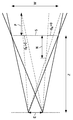
도 1은 디스패리티를 규정하는 여러 일반적인 개념들 및 파라미터들을 도시한다. 도 1은 눈의 거리(E)에 의해 떨어져 이격되고, 이중 화살표(E)의 모서리들에 위치되는 두 뷰포인트(viewpoint)들을 도시한다. 뷰잉 거리(Z)를 두고, 점선으로 표시되며 3차원 정보를 디스플레이하는데 이용되는 스크린(S)이 위치된다. 그와 같은 스크린은 실제로 예를 들어 시간 또는 스펙트럼 순차 디스플레이(sequential display)일 수 있고, 상기 디스플레이는 적절한 안경을 착용하고 있는 관찰자의 눈에 각각의 뷰포인트에 대한 적절한 이미지 정보를 대안으로 제공한다. 여기서 스크린(S)은 제로 디스패리티로 배치되고, W는 스크린의 폭을 나타낸다. N(근)은 스크린(S) 앞의 최대 감지 깊이를 나타낸다. 마찬가지로, F(원)는 스크린(S) 뒤의 최대 감지 깊이를 나타낸다.1 illustrates several general concepts and parameters that define disparity. FIG. 1 shows two viewpoints spaced apart by the distance E of the eye and located at the corners of the double arrow E. FIG. With the viewing distance Z, the screen S, which is indicated by dotted lines and used to display three-dimensional information, is located. Such a screen may in fact be, for example, a time or spectral sequential display, which alternatively provides appropriate image information for each viewpoint to the eyes of the observer wearing appropriate eyeglasses. The screen S is here arranged with zero disparity, and W represents the width of the screen. N (root) represents the maximum detection depth in front of the screen (S). Similarly, F (circle) represents the maximum detection depth behind the screen S.
라인(dN)은 스크린(S) 앞 N에 위치되어 있는 물체의 감지 디스패리티를 나타내고, 디스패리티 값(dN)은 여기서 음이고, 또한 교차 디스패리티로 칭해지며:Line d N represents the sensing disparity of the object located in front of screen S, and the disparity value d N is here negative and is also referred to as cross disparity:
dN = N E /(Z - N) [1]d N = NE / (Z-N) [1]
로 표현될 수 있다.It can be expressed as.
라인(dF)은 스크린(S) 뒤에 F에 위치되어 있는 물체의 감지 디스패리티를 나타내고, 디스패리티 값(dF)은 여기서 양이고, 또한 비-교차 디스패리티로 칭해지며:The line d F represents the sensing disparity of the object located at F behind the screen S, and the disparity value d F is positive here, also called non-crossing disparity:
dF = F E /(Z + F) [2]dF = F E / (Z + F) [2]
로 표현될 수 있다.It can be expressed as.
실제로, 최대 디스패리티는 눈의 거리(E) 아래에 있어서 편안한 뷰잉을 가능하게 해야만 한다. 실제로 최대 디스패리티는 바람직하게 사람들 사이의 눈의 거리의 변화를 감안하여 평균 눈의 거리(E) 아래에 있는 값으로 세팅(setting)된다.Indeed, the maximum disparity should allow for comfortable viewing under the distance E of the eye. In practice the maximum disparity is preferably set to a value below the average eye distance E, taking into account changes in the eye distance between people.
최대 양의 디스패리티에 대응하는 픽셀들의 수인 최대 양의 스크린 시차(parallax)는 스크린 폭(W) 및 스크린(S)의 해상도에 좌우된다는 것이 주의된다.Note that the maximum amount of screen parallax, the number of pixels corresponding to the maximum amount of disparity, depends on the screen width W and the resolution of the screen S.
도 2a는 3차원 입력 신호의 디스패리티 히스토그램(205)을 도시한다. 히스토그램(205)은 입력된 3차원 신호에, 즉 3차원 입력 신호의 전체 공간 에어리어에 기초하여 결정된다. 대안으로 디스패리티 히스토그램은 3차원 입력 신호의 전체 공간 에어리어의 대표적인 샘플들로 컴파일될 수 있다.2A shows a
도 2a에서 d-축을 따라 가장 가까운 디스패리티 값은 지점(C)이고, 음(negative)의 디스패리티를 갖는다. 가장 먼 디스패리티 값은 d-축에 따른 지점(B)이고, 양(positive)의 디스패리티를 갖는다. 히스토그램(205)에 기초하여 본 발명에 따른 방법에서 이용하기 위한 원 디스패리티 추정치는 지점(B)에 대응한다.In FIG. 2A, the closest disparity value along the d-axis is point C, with negative disparity. The furthest disparity value is point B along the d-axis and has a positive disparity. The original disparity estimate for use in the method according to the invention based on the
히스토그램(205)은 히스토그램을 우측으로 이동하고 있는 뷰어로부터 3차원적으로 멀어지는 입력의 디스패리티 범위를 시프트하기 위해 디스패리티 범위 내에서 이용 가능한 헤드룸(215)이 존재한다는 것을 표시한다.
오버레이가 각각의 도면들에서 특정한 공간 영역들 내에 배치될 필요가 있는 상황을 고려하자. 도 2a는 또한 관련된 공간 영역에서의 입력된 3차원 신호에 대한 디스패리티 히스토그램을 도시한다. 공간 영역에 대한 3차원 입력 신호의 히스토그램은 굵은 파선(205')으로 표시된다. 히스토그램(205')에 기초하여, 이 공간 영역에 대한 가장 작은 디스패리티 값을 나타내는 근 디스패리티 추정치는 지점(A)에 대응한다. 이 특정한 공간 영역이 더 작은(즉, 더욱 음인) 디스패리티 값들을 포함하지 않으므로, 오버레이의 배치를 위한 공간 영역 내에 실질적인 헤드룸(210)이 이미 존재하고 있음을 주목하라.Consider the situation where an overlay needs to be placed in specific spatial regions in each of the figures. 2A also shows a disparity histogram for the input three-dimensional signal in the associated spatial domain. The histogram of the three-dimensional input signal for the spatial domain is represented by the thick dashed line 205 '. Based on the histogram 205 ', a near disparity estimate representing the smallest disparity value for this spatial region corresponds to point A. Note that since this particular spatial region does not contain smaller (ie, more negative) disparity values,
오버레이의 배치를 위한 공간 영역은 전형적으로 윤곽선(outline)에 의해 규정되는 블록 또는 세그먼트(segment)이고, 그와 같으므로 이후에 기술되는 바와 같이, 있는 그대로의 뷰에 대한 디스패리티 추정치를 결정하는데 이용되는 샘플 지점들과는 명백하게 상이함을 주목하라.The spatial area for the placement of the overlay is typically a block or segment defined by an outline, and as such is used to determine the disparity estimate for the view as it is described later. Note that the sample points are clearly different.
오버레이의 배치를 위한 공간 영역에 실질적인 헤드룸이 이미 존재할지라도, 디스패리티 시프트(DS) 만큼 뷰어로부터 멀어지는 입력 3차원 비디오 신호의 디스패리티 범위를 시프트함으로써 훨씬 더 많은 헤드룸을 생성하는 것이 가능하고, 여기서 DS < E - B이다. 비록 엄밀하게 필요하지 않을지라도, 다양한 사용자들 사이의 상이한 눈의 거리들을 수용하기 위해 마진(215')으로 도 2b에 표시되는 바와 같이 마진((E - B) - DS))을 보존하는 것이 바람직하다. 결과적으로 본 발명은 오버레이의 배치를 위한 디스패리티 영역에서 추가 이득을 제공한다.Although substantial headroom already exists in the spatial area for the placement of the overlay, it is possible to generate even more headroom by shifting the disparity range of the input three-dimensional video signal away from the viewer by a disparity shift (DS), Where DS <E-B. Although not strictly necessary, it is desirable to preserve the margin ((E-B)-DS)) as shown in Figure 2B with margin 215 'to accommodate different eye distances between the various users. Do. As a result, the present invention provides an additional gain in the disparity area for placement of the overlay.
히스토그램(220)은 오버레이가 이 공간 영역 내에 전체가 배치될 때, 오버레이의 디스패리티 히스토그램을 나타내고, 본 히스토그램은 또한 전체 이미지상의 오버레이의 히스토그램이다. 디스패리티 시프트의 결과로, 현재 자막들과 같은 오버레이 정보를 오버레이 뷰잉의 편안함을 개선하는 제로 디스패리티 평면에 또는 그 근방에 배치하는 것이 가능하다.
상술한 바와 같이, 원 및 근 디스패리티 추정치는 입력 3차원 비디오 신호가 제공되는 디스패리티 히스토그램 정보에 기초하여 결정될 수 있다. 대안으로, 원 및 근 디스패리티 추정치는 당업자에게 공지되어 있는 알고리즘들을 이용하여 입력 3차원 비디오 신호로부터 도출될 수 있다. 그와 같은 알고리즘의 예는 미국 캘리포니아 산호세에서, 2000년 1월 23일 내지 28일에 Electronic Imaging Stereoscopic Displays and Virtual Reality Syst.에 대한 IS&T/SPIE 심포지엄에서 Konrad 등에 의한 "Dense disparity estimation from feature correspondences"에서 제공된다.As described above, the original and near disparity estimates may be determined based on disparity histogram information provided with the input three-dimensional video signal. Alternatively, the original and near disparity estimates can be derived from the input three-dimensional video signal using algorithms known to those skilled in the art. An example of such an algorithm is described in "Dense disparity estimation from feature correspondences" by Konrad at the IS & T / SPIE Symposium on Electronic Imaging Stereoscopic Displays and Virtual Reality Syst., January 23-28, 2000, in San Jose, California, USA. Is provided.
도 3은 본 발명에 의해 제한되는 바와 같이 디스패리티를 시프트하는 프로세스를 도시한다. 좌수 측에는 스테레오 입력 비디오 신호로부터의 이미지 쌍(LV1 및 RV1)이 도시된다. 이미지들은 제로 디스패리티에 배치되는 회색 블록(310 및 310') 및 각각의 이미지들(LV1 및 RV1) 내의 음의 디스패리티에서 블록의 앞에 배치되는 백색 디스크(305 및 305')를 도시한다.3 shows a process for shifting disparity as limited by the present invention. On the left hand side the image pairs LV1 and RV1 from the stereo input video signal are shown. The images show the
회색 블록(310 및 310')의 모서리들에 있는 얇은 점선의 수직 라인들로부터 확인될 수 있는 바와 같이, 직사각형은 제로 디스패리티를 갖는데 왜냐하면 이는 좌측 및 우측 이미지에서 동일한 위치에 배치되기 때문이다.As can be seen from the thin dotted vertical lines at the corners of the
디스크(305 및 305')는 음의 스크린 시차를 가지는, 즉 우측 이미지(RV1)에서 디스크(305')는 좌측 이미지(LV1)에서의 디스크(305)의 위치의 좌측에 있다. 결과적으로 이는 디스플레이 앞에서 시각화된다.The
장면을 후방으로 시프트하기 위해서, RV1을 우측으로 시프트하여 RV1'을 획득한다. RV1'를 LV1과 비교함으로써 이제 디스크(305')가 제로 디스패리티를 갖고 직사각형이 양의 디스패리티를 갖는 것을 인지한다.To shift the scene backward, shift RV1 to the right to obtain RV1 '. By comparing RV1 'to LV1, it is now recognized that disk 305' has zero disparity and the rectangle has positive disparity.
시프트된 이미지를 스테레오 디스플레이에 맞추기 위해 시프트된 이미지(RV1')는 우수 측 상에서 크롭되고 좌수 측으로 동일한 양만큼 확장되어 RV1''에 도달한다. LV1 및 RV1''은 결국, 원래의 LV1-RV1 쌍에 비해 장면이 후방으로 시프트된 새로운 스테레오 쌍으로서 함께 시각화될 수 있다. 결과적으로 쌍 LV1-RV1''은 쌍 LV1-RV1보다 오버레이의 배치를 위한 헤드룸을 더 많이 갖는다.In order to fit the shifted image to the stereo display, the shifted image RV1 'is cropped on the even side and extended by the same amount to the left hand side to reach RV1' '. LV1 and RV1 '' can eventually be visualized together as a new stereo pair with the scene shifted backwards relative to the original LV1-RV1 pair. As a result, the pair LV1-RV1 '' has more headroom for the placement of the overlay than the pair LV1-RV1.
비록 상기 예에서 뷰들 중 단 하나만이 시프트될지라도, 좌측 이미지(LV1) 및 우측 이미지(RV1) 모두를 동일한 반대의 양만큼 시프트하는 것이 또한 가능하다는 것이 주목되어야 하고, 여기서 결합된 양은 RV1'의 시프트에 대응한다. 결과적으로 둘 모두의 시프트된 이미지들은 확장되어야만 할 것이지만, 확장 영역은 도 3에서 크롭되고 확장된 크기의 절반이다. 결과적으로 확장으로 인한 아티팩트들은 더욱 균일하게 확산될 것이다.Although only one of the views in the above example is shifted, it should be noted that it is also possible to shift both the left image LV1 and the right image RV1 by the same opposite amount, where the combined amount is the shift of RV1 '. Corresponds to. As a result both shifted images will have to be expanded, but the extended area is half of the cropped and expanded size in FIG. 3. As a result, artifacts due to expansion will spread more evenly.
다중-뷰 콘텐츠, 예를 들어 세 개의 뷰들을 시프트할 때, 중심 이미지를 보존하는 것과 좌측 및 우측 이미지를 각각 확장하는 것이 가능하다. 상기 방식의 디스패리티 범위의 시프팅은 후속해서 부가 다중-뷰 이미지들로 그리고 이미지들의 임의의 적절한 양의 시프트로 확장될 수 있어서, 결과적으로 이들 사이에는 동일한 상대적 양의 시프트가 발생하는 것이 당업자에게는 명확할 것이다.When shifting multi-view content, for example three views, it is possible to preserve the center image and expand the left and right images respectively. Shifting of the disparity range in this manner can subsequently be extended to additional multi-view images and to any suitable amount of shift of the images, such that the same relative amount of shift between them will occur to those skilled in the art. Will be clear.
입력 3차원 비디오 신호를 적응시킬 때, 여러 선택 사항이 이용 가능하며, 예를 들어 제 1 선택사항은 단지 크롭만을 이용하는 것이다. 스테레오 비디오 신호를 고려하며, 이 경우에 비디오 신호 내의 좌측 및 우측 이미지 이 둘 모두를 동일한 양만큼 크롭하는 것이 가능하다. 이미지 종횡비(image aspect ratio)가 문제가 아닌 경우, 크롭된 뷰들은 확장을 필요로 하지 않으므로 있는 그대로 이용될 수 있다. 이를 행하는 장점은 확장이 필요하지 않으므로, 확장 아티팩트들이 도입되지 않는다는 점이다. 제 2 선택사항은 상술한 바와 같이 크롭핑(cropping) 및 확장을 이용하는 것이다. 스테레오 비디오 신호를 고려하면, 이 경우에 비디오 신호 내의 좌측 및 우측 이미지들 이 둘 모두를 동일한 양만큼 크롭하여 후속해서 도 3에 도시된 바와 같이 각각의 뷰들을 확장하는 것이 가능하다. 확장을 이용하는 장점은 입력 3차원 비디오 신호의 종횡비가 보존될 수 있다는 점이다. 상기 선택사항들의 목록은 철저한 것이 아님이 주목된다.When adapting the input three-dimensional video signal, several options are available, for example the first option is to use only crop. Consider the stereo video signal, in which case it is possible to crop both the left and right images in the video signal by the same amount. If the image aspect ratio is not a problem, then cropped views can be used as-is as they do not require expansion. The advantage of doing this is that no extension artifacts are introduced since no extension is needed. The second option is to use cropping and expansion as described above. Considering the stereo video signal, in this case it is possible to crop both the left and right images in the video signal by the same amount to subsequently expand the respective views as shown in FIG. 3. The advantage of using expansion is that the aspect ratio of the input three-dimensional video signal can be preserved. It is noted that the list of options is not exhaustive.
도 4는 다중 뷰들을 포함하는 입력 3차원 비디오 신호를 프로세싱하기 위한 본 발명에 따른 방법(400)의 흐름도를 제공한다. 상기 방법은 입력 3차원 비디오 신호에 대한 가장 큰 디스패리티 값을 나타내는 원 디스패리티 추정치 및 입력 3차원 비디오 신호 내의 공간 영역에 대한 가장 작은 디스패리티 값을 나타내는 근 디스패리티 추정치를 결정하는(405) 단계를 포함한다. 상술한 바와 같이 각각의 디스패리티 추정치들은 메타데이터에 기초할 수 있거나 대안으로 입력 3차원 비디오 신호의 이미지 콘텐츠에 기초하여 결정될 수 있다.4 provides a flow diagram of a
상기 방법은 원 디스패리티 추정치에 기초하는 디스패리티 시프트에 의해 입력 3차원 비디오 신호를 후방으로 시프트함으로써 3차원 비디오 신호를 적응시키는 단계(410) 및 근 디스패리티 추정치 및 디스패리티 시프트에 기초하여 시프트된 3차원 비디오 신호에 대해 공간 영역 내에 오버레이를 생성하는 단계(415)를 더 포함한다.The method includes adapting the three-dimensional video signal by shifting the input three-dimensional video signal backward by a disparity shift based on the original disparity estimate and the shifted based on the near disparity estimate and the disparity shift. Generating 415 an overlay in the spatial region for the three-dimensional video signal.
바람직하게는 상기 방법은 시프트된 3차원 비디오 신호 위에 오버레이를 오버레잉하는 단계(420)를 더 포함한다.Advantageously, the method further comprises overlaying 420 over said shifted three-dimensional video signal.
상술한 바와 같이 입력 3차원 비디오 신호를 적응시키는 단계는 변경된 디스패리티 범위를 획득하기 위해 각각의 뷰들을 패딩 픽셀들을 크롭핑하고(425) 확장하는 단계를 포함할 수 있다.Adapting an input three-dimensional video signal as described above may include cropping and expanding 425 padding pixels of respective views to obtain a changed disparity range.
스테레오 신호의 경우, 하나 또는 바람직하게는 양 뷰들이 크롭핑되고 후속해서 확장된다. 심지어 N을 구비한 N-뷰 멀티뷰 이미지의 경우, N-1 바람직하게는 N-뷰들은 상술한 바와 같이 크롭핑되고 확장된다.In the case of a stereo signal, one or preferably both views are cropped and subsequently expanded. Even for N-view multiview images with N, N-1 preferably N-views are cropped and expanded as described above.
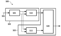
도 5a는 다중 뷰들을 포함하는 입력 3차원 비디오 신호를 프로세싱하기 위한 본 발명에 따른 시스템(500)을 제공한다. 시스템(500)은 입력 3차원 비디오 신호에 대한 가장 큰 디스패리티 값을 나타내는 원 디스패리티 추정치 및 입력 3차원 비디오 신호 내의 공간 영역에 대한 가장 작은 디스패리티 값을 나타내는 근 디스패리티 추정치를 결정하기 위한 디스패리티 결정기(505)를 포함한다. 상술한 바와 같이, 디스패리티 결정기(505)는 디스패리티 추정기로 구현될 수 있다. 상기 시스템은 원 디스패리티 추정치에 기초한 디스패리티 시프트에 의해 3차원 비디오 신호를 후방으로 시프트함으로써 3차원 비디오 신호를 적응하도록 배열되는 디스패리티 시프터(shifter)(510)를 더 포함한다. 상기 시스템(500)은 근 디스패리티 추정치 및 디스패리티 시프트에 기초하여 시프트된 3차원 비디오 신호에 대하여 오버레이 안전 에어리어 내에 오버레이를 생성하도록 배열되는 오버레이 생성기(515)를 더 포함한다.5A provides a
바람직하게는, 상기 시스템(500)은 또한 시프트된 3차원 비디오 신호 위에 오버레이를 오버레잉하도록 배열되는 비디오 믹서(520)를 포함한다. 도 5a에 도시된 바와 같은 상기 시스템(500)은 콘텐츠의 오프라인 프로세싱을 위해서 개인용 컴퓨터 또는 다른 컴퓨팅 플랫폼(computing platform) 상에서 구현될 수 있다. 대안으로, 이는 예를 들어 블루-레이(Blue-ray) 디스크 재생 가능 디바이스, 또는 셋탑 박스 또는 3D-TV에서 구현될 수 있다.Preferably, the
도 5b는 본 발명에 따른 부가 시스템(500)을 도시하고, 여기서 상기 시스템은 분석 디바이스(502) 및 합성 디바이스(503)로 분할되고, 결합된 양 디바이스들은 도 5a에 제공되는 바와 같이 시스템(500)에서 발견되는 기능을 구현한다.FIG. 5B illustrates an
상기 설명은 명료성을 위해 상이한 기능 유닛들 및 프로세서들을 참조하여 본 발명의 실시예들을 기술했음이 인식될 것이다. 그러나, 상이한 기능 유닛들 또는 프로세서들 사이에 임의로 적절하게 기능을 분포하는 것은 본 발명을 손상시키지 않고 이용될 수 있음이 명확할 것이다. 예를 들어, 개별 유닛들, 프로세서들 또는 제어기들에 의해 수행될 도시된 기능은 동일한 프로세서 또는 제어기들에 의해 수행될 수 있다. 그러므로, 특정한 기능 유닛들을 참조하는 것은 단지 엄격한 논리적 또는 물리적 구조 또는 조직을 나타내기보다는 기술된 기능을 제공하기 위한 적절한 수단을 참조하는 것으로 인지되어야만 한다.It will be appreciated that the above description has described embodiments of the invention with reference to different functional units and processors for clarity. However, it will be apparent that arbitrarily appropriately distributing the function among different functional units or processors can be used without compromising the present invention. For example, the functionality shown to be performed by individual units, processors or controllers may be performed by the same processor or controllers. Therefore, reference to specific functional units should be recognized as referring to appropriate means for providing the described functionality rather than merely representing a strict logical or physical structure or organization.
본 발명은 하드웨어, 소프트웨어, 펌웨어 또는 이들의 임의의 조합을 포함하는 임의의 적절한 형태로 구현될 수 있다. 본 발명은 선택적으로 하나 이상의 데이터 프로세서들 및/또는 디지털 신호 프로세서들에서 운영되는 컴퓨터 소프트웨어로 적어도 부분적으로 구현될 수 있다. 본 발명의 실시예의 요소들 및 컴포넌트들은 임의의 적절한 방식으로 물리적, 기능적 그리고 논리적으로 구현될 수 있다. 실제로 기능은 단일 유닛으로, 복수의 유닛들로, 또는 다른 기능 유닛들의 일부로 구현될 수 있다. 이와 같으므로, 본 발명은 단일 유닛에서 구현될 수 있거나 또는 상이한 유닛들 및 프로세서들 사이에 물리적으로 그리고 기능적으로 분배될 수 있다.The invention may be implemented in any suitable form including hardware, software, firmware or any combination thereof. The invention may optionally be implemented at least partly in computer software running on one or more data processors and / or digital signal processors. The elements and components of an embodiment of the present invention may be implemented physically, functionally and logically in any suitable manner. Indeed the functionality may be implemented in a single unit, in a plurality of units, or as part of other functional units. As such, the invention may be implemented in a single unit or may be physically and functionally distributed between different units and processors.
본 발명이 일부 실시예들과 함께 설명되었을지라도, 본 발명은 본원에 진술된 특정한 형태로 제한되도록 의도되지 않는다. 오히려, 본 발명의 범위는 첨부 청구항들에 의해서만 제한된다. 게다가, 특징이 특정한 실시예들과 함께 기술되는 것처럼 보일 수 있을지라도, 당업자는 기술된 실시예들의 다양한 특징들이 본 발명에 따라 결합될 수 있음을 인식할 것이다. 청구항들에서, 용어 포함하는(comprising)은 다른 요소들 또는 단계들의 존재를 배제하지 않는다.Although the present invention has been described in conjunction with some embodiments, it is not intended to be limited to the specific form set forth herein. Rather, the scope of the present invention is limited only by the accompanying claims. In addition, although a feature may appear to be described in conjunction with particular embodiments, one skilled in the art will recognize that various features of the described embodiments may be combined in accordance with the present invention. In the claims, the term comprising does not exclude the presence of other elements or steps.
더욱이, 개별적으로 기재될지라도, 복수의 수단들, 요소들 또는 방법 단계들은 예를 들어 단일 유닛 또는 프로세서에 의해 구현될 수 있다. 추가적으로, 개별 특징들이 상이한 청구항들에 포함될지라도, 이는 가능하게도 유용하게 결합될 수 있고 상이한 청구항들에의 포함이 특징들의 결합이 실현 가능하지 않고/않거나 유용하지 않다는 것을 의미하지 않는다. 또한 하나의 범주의 청구항들 내에 특징이 포함되는 것은 특징들의 결합이 이 범주로 제한되는 것을 의미하지 않고 오히려 특징이 적절할 때 다른 청구항 범주들에 동일하게 적용 가능하다. 더욱이, 청구항들에서의 특징들의 순서는 특징들이 작용되어야만 하는 임의의 특정한 순서를 의미하지 않고 특히 방법 청구항에서의 개별 단계들의 순서는 단계들이 이 순서로 실행되어야만 하는 것을 의미하지 않는다. 오히려, 단계들은 임의의 적절한 순서로 수행될 수 있다. 게다가, 단수의 참조들은 복수를 배제하지 않는다. 그러므로 "a", "an", "first", "second" 등을 언급하는 것은 복수를 배제하지 않는다. 청구항들 내의 참조 부호들은 예를 단지 명확하게 하도록 제공되고 아무튼 청구항들의 범위를 제한하는 것으로 해석되어서는 안 된다.Moreover, although described separately, a plurality of means, elements or method steps may be implemented by eg a single unit or processor. Additionally, although individual features may be included in different claims, this may possibly be usefully combined and inclusion in different claims does not mean that the combination of features is not feasible and / or useful. Also, the inclusion of a feature in one category of claims does not mean that the combination of features is limited to this category, but rather is equally applicable to other claim categories when the feature is appropriate. Moreover, the order of features in the claims does not imply any particular order in which the features must be acted upon and in particular the order of the individual steps in the method claim does not imply that the steps must be executed in this order. Rather, the steps may be performed in any suitable order. In addition, singular references do not exclude a plurality. Therefore, referring to "a", "an", "first", "second", etc. does not exclude a plurality. Reference signs in the claims are provided for clarity of illustration only and should not be construed as limiting the scope of the claims in any way.
210 : 헤드룸 500 : 시스템
305 : 디스크210: headroom 500: system
305 disk
Claims (14)
상기 입력 3차원 비디오 신호에 대하여 가장 큰 디스패리티(disparity) 값을 나타내는 원 디스패리티(far disparity) 추정치(B),
상기 입력 3차원 비디오 신호 내의 공간 영역에 대하여 가장 작은 디스패리티 값을 나타내는 근 디스패리티(near disparity) 추정치(A)를 결정하는 단계(405),
상기 원 디스패리티 추정치에 기초하여 상기 입력 3차원 비디오 신호를 디스패리티 시프트(DS; disparity shift)에 의해 후방으로 시프트함으로써 상기 입력 3차원 비디오 신호를 적응시키는 단계(310), 및
상기 근 디스패리티 추정치 및 상기 디스패리티 시프트(DS)에 기초하여 상기 시프트된 3차원 비디오 신호에 대해 공간 영역 내에 오버레이를 생성하는 단계(315)를 포함하는, 입력 3차원 비디오 신호를 프로세싱하는 방법.A method (400) for processing an input three-dimensional video signal comprising multiple views:
A far disparity estimate (B) representing the largest disparity value for the input three-dimensional video signal,
Determining a near disparity estimate A representing a smallest disparity value for a spatial region in the input three-dimensional video signal (405),
Adapting the input three-dimensional video signal by shifting the input three-dimensional video signal backwards by disparity shift (DS) based on the original disparity estimate (310), and
Generating an overlay (315) in a spatial region for the shifted three-dimensional video signal based on the near disparity estimate and the disparity shift (DS).
상기 시프트된 3차원 비디오 신호 위에 오버레이를 오버레잉하는 단계(320)를 추가로 포함하는, 입력 3차원 비디오 신호를 프로세싱하는 방법.The method of claim 1,
Overlaying (320) an overlay over the shifted three-dimensional video signal.
상기 원 디스패리티 추정치(B) 및 상기 근 디스패리티 추정치(A) 이 둘 모두는 샷 기반 및 샷들의 그룹 기반 중 하나인, 입력 3차원 비디오 신호를 프로세싱하는 방법.The method of claim 1,
Wherein both the original disparity estimate (B) and the near disparity estimate (A) are one of shot based and group based of shots.
상기 디스패리티 시프트(DS)는 다중 뷰들의 인접 뷰들 사이에 있는 미리 결정된 최대 디스패리티 값에 기초하는, 입력 3차원 비디오 신호를 프로세싱하는 방법.The method of claim 1,
Wherein the disparity shift (DS) is based on a predetermined maximum disparity value between adjacent views of multiple views.
상기 미리 결정된 최대 디스패리티 값은:
선택되는 눈의 거리 값 및 안전 마진(safety margin: M), 및
사용자 규정 최대 디스패리티 값
중 하나에 기초하는, 입력 3차원 비디오 신호를 프로세싱하는 방법.The method of claim 4, wherein
The predetermined maximum disparity value is:
Chosen eye distance value and safety margin (M), and
User qualified maximum disparity value
A method of processing an input three dimensional video signal based on one of the following.
상기 오버레이는:
자막들(subtitles),
클로즈드 캡션(closed caption) 정보,
사용자 인터페이스 정보, 및
부가적으로 입력되는 3차원 입력 신호 중 적어도 하나를 포함하는, 3차원 비디오 신호를 프로세싱하는 방법.6. The method according to any one of claims 1 to 5,
The overlay is:
Subtitles,
Closed caption information,
User interface information, and
And at least one of an additionally input three-dimensional input signal.
상기 입력 3차원 비디오 신호를 적응시키는 단계는:
크롭핑된 뷰가 상기 뷰들 중 다른 뷰와 결합될 때 변경된 디스패리티 범위를 획득하도록, 한 측에서 적어도 하나의 뷰를 크롭핑(crop)(325)하는 단계,
확장되는 크롭핑된 뷰가 상기 뷰들 중 다른 뷰와 결합될 때 변경된 디스패리티 범위를 획득하도록, 한 측에서 적어도 하나의 뷰를 크롭핑(325)하고 상기 한 측의 반대 측에서 적어도 하나의 크롭핑된 뷰를 확장(330)하는 단계, 및
상기 확장되는 스케일링(scaling)된 크롭핑된 뷰가 다른 하나의 스케일링된 크롭핑된 뷰와 결합할 때 변경된 디스패리티 범위를 획득하도록, 상기 적어도 하나의 뷰를 크롭핑(325)하고 이를 전폭(full-width)으로 역으로 스케일링하는 단계 중 하나를 포함하는, 입력 3차원 비디오 신호를 프로세싱하는 방법.6. The method according to any one of claims 1 to 5,
Adapting the input three-dimensional video signal includes:
Cropping (325) at least one view on one side to obtain a changed disparity range when the cropped view is combined with another of the views,
Crop 325 at least one view on one side and at least one cropping on the opposite side of the one side to obtain an altered disparity range when the extended cropped view is combined with another of the views. Expanding (330) the compiled view, and
Crop 325 and full the at least one view to obtain a changed disparity range when the extended scaled cropped view combines with another scaled cropped view. -inverse scaling by (width)).
상기 방법은 시프트된 3차원 비디오 신호의 원 및 근 디스패리티를 나타내는 시프트된 3차원 비디오 신호에서 메타데이터를 임베딩(embedding)하는 단계를 추가로 포함하는, 입력 3차원 비디오 신호를 프로세싱하는 방법.The method of claim 1,
The method further comprises embedding metadata in the shifted three-dimensional video signal representing the original and near disparity of the shifted three-dimensional video signal.
상기 방법은 상기 오버레이를 포함하는 상기 시프트된 3차원 비디오 신호에 메타데이터를 임베딩하는 단계를 포함하고, 상기 메타데이터는 상기 오버레이를 포함하는 상기 시프트된 3차원 비디오 신호의 원 디스패리티 및 근 디스패리티를 나타내는, 입력 3차원 비디오 신호를 프로세싱하는 방법.The method of claim 2,
The method includes embedding metadata in the shifted three-dimensional video signal that includes the overlay, wherein the metadata includes original disparity and near disparity of the shifted three-dimensional video signal that includes the overlay. And a method for processing the input three-dimensional video signal.
상기 입력 3차원 비디오 신호에 대해 가장 큰 디스패리티 값을 나타내는 원 디스패리티 추정치, 및
상기 입력 3차원 비디오 신호 내의 공간 영역에 대해 가장 작은 디스패리티 값을 나타내는 근 디스패리티 추정치를 결정하기 위한, 디스패리티 결정기(505),
상기 입력 3차원 비디오 신호를 상기 원 디스패리티 추정치에 기초하는 디스패리티 시프트에 의해 후방으로 시프트함으로써 상기 입력 3차원 비디오 신호를 적응시키도록 배열되는 디스패리티 시프터(shifter)(510), 및
상기 근 디스패리티 추정치 및 상기 디스패리티 시프트에 기초하여 오버레이 안전 에어리어 내에 스프트된 3차원 비디오 신호에 대한 오버레이를 생성하도록 배열되는 오버레이 생성기(515)를 포함하는, 입력 3차원 비디오 신호를 프로세싱하는 시스템.In a system 500 for processing an input three-dimensional video signal comprising multiple views:
An original disparity estimate representing the largest disparity value for the input three-dimensional video signal, and
Disparity determiner 505 for determining a near disparity estimate that represents the smallest disparity value for a spatial region within the input three-dimensional video signal;
A disparity shifter 510 arranged to adapt the input three-dimensional video signal by shifting the input three-dimensional video signal backward by a disparity shift based on the original disparity estimate, and
A overlay generator 515 arranged to generate an overlay for the three-dimensional video signal shifted within the overlay safety area based on the near disparity estimate and the disparity shift. .
상기 오버레이를 상기 시프트된 3차원 비디오 신호 위에 오버레잉하도록 배열되는 비디오 믹서(video mixer)를 추가로 포함하는, 입력 3차원 비디오 신호를 프로세싱하는 시스템.The method of claim 10,
And a video mixer arranged to overlay the overlay over the shifted three-dimensional video signal.
상기 디스패리티 추정기(505)는 샷 단위 기반 및 샷들의 그룹 단위 기반 중 하나에 대한 상기 원 디스패리티 추정치 및 상기 근 디스패리티 추정치를 결정하도록 배열되는 입력 3차원 비디오 신호를 프로세싱하는 시스템.The method according to claim 11 or 12,
And the disparity estimator (505) is arranged to determine the original disparity estimate and the near disparity estimate for one of a shot unit basis and a group unit basis of shots.
상기 디스패리티 시프트(DS)는 상기 다중 뷰들의 인접한 뷰들 사이에 있는 미리 결정된 최대 디스패리티 값에 기초하는, 입력 3차원 비디오 신호를 프로세싱하는 시스템.The method according to claim 11 or 12,
The disparity shift (DS) is based on a predetermined maximum disparity value between adjacent views of the multiple views.
Applications Claiming Priority (2)
| Application Number | Priority Date | Filing Date | Title |
|---|---|---|---|
| EP08167112.5 | 2008-10-21 | ||
| EP08167112 | 2008-10-21 |
Publications (2)
| Publication Number | Publication Date |
|---|---|
| KR20110086079A true KR20110086079A (en) | 2011-07-27 |
| KR101633627B1 KR101633627B1 (en) | 2016-06-27 |
Family
ID=40352251
Family Applications (1)
| Application Number | Title | Priority Date | Filing Date |
|---|---|---|---|
| KR1020117011335A Expired - Fee Related KR101633627B1 (en) | 2008-10-21 | 2009-10-16 | Method and system for processing an input three dimensional video signal |
Country Status (9)
| Country | Link |
|---|---|
| US (1) | US9036006B2 (en) |
| EP (1) | EP2351377A1 (en) |
| JP (1) | JP5567578B2 (en) |
| KR (1) | KR101633627B1 (en) |
| CN (1) | CN102204261B (en) |
| BR (1) | BRPI0914459A2 (en) |
| RU (1) | RU2519433C2 (en) |
| TW (1) | TWI545934B (en) |
| WO (1) | WO2010046824A1 (en) |
Families Citing this family (53)
| Publication number | Priority date | Publication date | Assignee | Title |
|---|---|---|---|---|
| JP5407968B2 (en) * | 2009-06-29 | 2014-02-05 | ソニー株式会社 | Stereoscopic image data transmitting apparatus and stereoscopic image data receiving apparatus |
| KR20110053159A (en) * | 2009-11-13 | 2011-05-19 | 삼성전자주식회사 | Method and apparatus for generating multimedia stream for three-dimensional reproduction of video additional reproduction information, and method and apparatus for receiving |
| JP2011109397A (en) * | 2009-11-17 | 2011-06-02 | Sony Corp | Image transmission method, image reception method, image transmission device, image reception device, and image transmission system |
| JP5477128B2 (en) | 2010-04-07 | 2014-04-23 | ソニー株式会社 | Signal processing apparatus, signal processing method, display apparatus, and program |
| JP2011228950A (en) * | 2010-04-20 | 2011-11-10 | Sony Corp | Data structure, image processing apparatus, image processing, method and program |
| JP2012010311A (en) | 2010-05-26 | 2012-01-12 | Sony Corp | Transmitter, transmission method, receiver, reception method and transmission/reception system |
| EP2469876B1 (en) * | 2010-06-17 | 2015-07-29 | FUJIFILM Corporation | Stereoscopic image display control apparatus and operation control method of the same |
| JP5505637B2 (en) | 2010-06-24 | 2014-05-28 | ソニー株式会社 | Stereoscopic display device and display method of stereoscopic display device |
| US20110316972A1 (en) * | 2010-06-29 | 2011-12-29 | Broadcom Corporation | Displaying graphics with three dimensional video |
| JP4996720B2 (en) * | 2010-06-30 | 2012-08-08 | 株式会社東芝 | Image processing apparatus, image processing program, and image processing method |
| KR101809479B1 (en) * | 2010-07-21 | 2017-12-15 | 삼성전자주식회사 | Apparatus for Reproducing 3D Contents and Method thereof |
| KR101816846B1 (en) * | 2010-08-19 | 2018-01-12 | 삼성전자주식회사 | Display apparatus and method for providing OSD applying thereto |
| EP2434764A1 (en) * | 2010-09-23 | 2012-03-28 | Thomson Licensing | Adaptation of 3D video content |
| US9049423B2 (en) * | 2010-12-01 | 2015-06-02 | Qualcomm Incorporated | Zero disparity plane for feedback-based three-dimensional video |
| TWI538475B (en) * | 2010-12-03 | 2016-06-11 | 皇家飛利浦電子股份有限公司 | 3d source device for outputting a three-dimensional image signal, 3d target device for receiving the same, methods of producing and consuming the same, and computer program product |
| EP2490452A1 (en) | 2011-02-21 | 2012-08-22 | Advanced Digital Broadcast S.A. | A method and system for rendering a stereoscopic view |
| US8988512B2 (en) * | 2011-04-14 | 2015-03-24 | Mediatek Inc. | Method for adjusting playback of multimedia content according to detection result of user status and related apparatus thereof |
| TWI467516B (en) * | 2011-04-26 | 2015-01-01 | Univ Nat Cheng Kung | Method for color feature extraction |
| US10054732B2 (en) | 2013-02-22 | 2018-08-21 | Reald Spark, Llc | Directional backlight having a rear reflector |
| EP2627093A3 (en) | 2012-02-13 | 2013-10-02 | Thomson Licensing | Method and device for inserting a 3D graphics animation in a 3D stereo content |
| US9031356B2 (en) | 2012-03-20 | 2015-05-12 | Dolby Laboratories Licensing Corporation | Applying perceptually correct 3D film noise |
| US9709723B2 (en) | 2012-05-18 | 2017-07-18 | Reald Spark, Llc | Directional backlight |
| US9188731B2 (en) | 2012-05-18 | 2015-11-17 | Reald Inc. | Directional backlight |
| TWI636283B (en) | 2012-05-18 | 2018-09-21 | 美商瑞爾D斯帕克有限責任公司 | Directional backlight, directional display device and control method thereof |
| US20130321572A1 (en) * | 2012-05-31 | 2013-12-05 | Cheng-Tsai Ho | Method and apparatus for referring to disparity range setting to separate at least a portion of 3d image data from auxiliary graphical data in disparity domain |
| JP6233870B2 (en) * | 2012-08-28 | 2017-11-22 | 稔 稲葉 | 3D image receiver |
| CN110234000B (en) * | 2013-06-17 | 2021-07-13 | 瑞尔D斯帕克有限责任公司 | Teleconferencing method and telecommunication system |
| US9739928B2 (en) | 2013-10-14 | 2017-08-22 | Reald Spark, Llc | Light input for directional backlight |
| TWI497444B (en) * | 2013-11-27 | 2015-08-21 | Au Optronics Corp | Method and apparatus for converting 2d image to 3d image |
| USD755803S1 (en) * | 2014-02-21 | 2016-05-10 | Samsung Electronics Co., Ltd. | Display screen or portion thereof with graphical user interface |
| USD768667S1 (en) * | 2014-02-21 | 2016-10-11 | Samsung Electronics Co., Ltd. | Display screen or portion thereof with graphical user interface |
| USD886847S1 (en) | 2014-04-11 | 2020-06-09 | Johnson Controls Technology Company | Display screen or portion thereof with graphical user interface |
| USD788785S1 (en) | 2014-04-11 | 2017-06-06 | Johnson Controls Technology Company | Display having a graphical user interface |
| USD857035S1 (en) | 2014-04-11 | 2019-08-20 | Johnson Controls Technology Company | Display screen or portion thereof with graphical user interface |
| WO2016057690A1 (en) | 2014-10-08 | 2016-04-14 | Reald Inc. | Directional backlight |
| RU2596062C1 (en) | 2015-03-20 | 2016-08-27 | Автономная Некоммерческая Образовательная Организация Высшего Профессионального Образования "Сколковский Институт Науки И Технологий" | Method for correction of eye image using machine learning and method of machine learning |
| EP3283906B1 (en) | 2015-04-13 | 2020-09-23 | RealD Spark, LLC | Wide angle imaging directional backlights |
| EP3400706B1 (en) | 2016-01-05 | 2022-04-13 | RealD Spark, LLC | Gaze correction of multi-view images |
| WO2017200950A1 (en) | 2016-05-19 | 2017-11-23 | Reald Spark, Llc | Wide angle imaging directional backlights |
| WO2017205183A1 (en) | 2016-05-23 | 2017-11-30 | Reald Spark, Llc | Wide angle imaging directional backlights |
| KR102732515B1 (en) | 2016-11-10 | 2024-11-20 | 삼성전자주식회사 | Holographic display apparatus providing increased eye box |
| CN110178072B (en) | 2017-01-04 | 2022-03-11 | 瑞尔D斯帕克有限责任公司 | Optical stacks for imaging directional backlights |
| WO2018187154A1 (en) | 2017-04-03 | 2018-10-11 | Reald Spark, Llc | Segmented imaging directional backlights |
| EP4293574A3 (en) | 2017-08-08 | 2024-04-03 | RealD Spark, LLC | Adjusting a digital representation of a head region |
| US11115647B2 (en) | 2017-11-06 | 2021-09-07 | Reald Spark, Llc | Privacy display apparatus |
| EP3743766B1 (en) | 2018-01-25 | 2026-02-11 | RealD Spark, LLC | Touch screen for privacy display |
| KR102566408B1 (en) | 2018-04-24 | 2023-08-11 | 삼성전자주식회사 | 3-dimensional image display apparatus and method providing expanded viewing window |
| US11163271B2 (en) | 2018-08-28 | 2021-11-02 | Johnson Controls Technology Company | Cloud based building energy optimization system with a dynamically trained load prediction model |
| US11159022B2 (en) | 2018-08-28 | 2021-10-26 | Johnson Controls Tyco IP Holdings LLP | Building energy optimization system with a dynamically trained load prediction model |
| CN116194812A (en) | 2020-09-16 | 2023-05-30 | 瑞尔D斯帕克有限责任公司 | Vehicle Exterior Lighting |
| US12585094B2 (en) | 2022-06-22 | 2026-03-24 | Reald Spark, Llc | Anamorphic directional illumination device |
| WO2024030274A1 (en) | 2022-08-02 | 2024-02-08 | Reald Spark, Llc | Pupil tracking near-eye display |
| US12282168B2 (en) | 2022-08-11 | 2025-04-22 | Reald Spark, Llc | Anamorphic directional illumination device with selective light-guiding |
Citations (2)
| Publication number | Priority date | Publication date | Assignee | Title |
|---|---|---|---|---|
| WO2006111893A1 (en) * | 2005-04-19 | 2006-10-26 | Koninklijke Philips Electronics N.V. | Depth perception |
| KR20080088305A (en) * | 2007-03-29 | 2008-10-02 | 삼성전자주식회사 | Method and apparatus for adjusting stereoscopic effect of stereo or multi-view image |
Family Cites Families (16)
| Publication number | Priority date | Publication date | Assignee | Title |
|---|---|---|---|---|
| US5790086A (en) * | 1995-01-04 | 1998-08-04 | Visualabs Inc. | 3-D imaging system |
| RU2097940C1 (en) * | 1995-04-18 | 1997-11-27 | Акционерное общество закрытого типа "Ракурс-ЗД" | Method for generation and displaying of three- dimensional image and device which implements said method |
| JPH11113028A (en) * | 1997-09-30 | 1999-04-23 | Toshiba Corp | 3D video display |
| GB2354389A (en) | 1999-09-15 | 2001-03-21 | Sharp Kk | Stereo images with comfortable perceived depth |
| JP2003284095A (en) * | 2002-03-27 | 2003-10-03 | Sanyo Electric Co Ltd | Stereoscopic image processing method and apparatus therefor |
| EP2357841B1 (en) * | 2002-03-27 | 2015-07-22 | Sanyo Electric Co., Ltd. | Method and apparatus for processing three-dimensional images |
| JP2004246725A (en) * | 2003-02-14 | 2004-09-02 | Sharp Corp | DISPLAY DEVICE, DISPLAY CONTROL METHOD, DISPLAY CONTROL PROGRAM, AND COMPUTER-READABLE RECORDING MEDIUM RECORDING THE SAME |
| JP4272901B2 (en) * | 2003-02-17 | 2009-06-03 | 株式会社マーキュリーシステム | Image processing apparatus, imaging apparatus, and program |
| JP2004274125A (en) * | 2003-03-05 | 2004-09-30 | Sony Corp | Image processing apparatus and method |
| US7417664B2 (en) * | 2003-03-20 | 2008-08-26 | Seijiro Tomita | Stereoscopic image picking up and display system based upon optical axes cross-point information |
| JP4525049B2 (en) * | 2003-10-24 | 2010-08-18 | ソニー株式会社 | Stereoscopic image processing apparatus and stereoscopic image generation method |
| GB0329312D0 (en) * | 2003-12-18 | 2004-01-21 | Univ Durham | Mapping perceived depth to regions of interest in stereoscopic images |
| JP2006325165A (en) * | 2005-05-20 | 2006-11-30 | Excellead Technology:Kk | Device, program and method for generating telop |
| DE102006030990A1 (en) * | 2005-11-14 | 2007-05-16 | Univ Muenster Wilhelms | A method and apparatus for monoscopically displaying at least a portion of an image on an autostereoscopic display device |
| WO2008038205A2 (en) * | 2006-09-28 | 2008-04-03 | Koninklijke Philips Electronics N.V. | 3 menu display |
| MX2009009871A (en) * | 2007-03-16 | 2010-05-19 | Thomson Licensing | System and method for combining text with three-dimensional content. |
-
2009
- 2009-10-16 JP JP2011531621A patent/JP5567578B2/en not_active Expired - Fee Related
- 2009-10-16 CN CN200980141834.1A patent/CN102204261B/en not_active Expired - Fee Related
- 2009-10-16 US US13/125,372 patent/US9036006B2/en not_active Expired - Fee Related
- 2009-10-16 WO PCT/IB2009/054564 patent/WO2010046824A1/en not_active Ceased
- 2009-10-16 EP EP09744197A patent/EP2351377A1/en not_active Withdrawn
- 2009-10-16 RU RU2011120445/08A patent/RU2519433C2/en not_active IP Right Cessation
- 2009-10-16 KR KR1020117011335A patent/KR101633627B1/en not_active Expired - Fee Related
- 2009-10-16 BR BRPI0914459A patent/BRPI0914459A2/en not_active Application Discontinuation
- 2009-10-19 TW TW098135301A patent/TWI545934B/en not_active IP Right Cessation
Patent Citations (2)
| Publication number | Priority date | Publication date | Assignee | Title |
|---|---|---|---|---|
| WO2006111893A1 (en) * | 2005-04-19 | 2006-10-26 | Koninklijke Philips Electronics N.V. | Depth perception |
| KR20080088305A (en) * | 2007-03-29 | 2008-10-02 | 삼성전자주식회사 | Method and apparatus for adjusting stereoscopic effect of stereo or multi-view image |
Also Published As
| Publication number | Publication date |
|---|---|
| TWI545934B (en) | 2016-08-11 |
| TW201027979A (en) | 2010-07-16 |
| KR101633627B1 (en) | 2016-06-27 |
| EP2351377A1 (en) | 2011-08-03 |
| US9036006B2 (en) | 2015-05-19 |
| CN102204261B (en) | 2016-08-24 |
| RU2011120445A (en) | 2012-11-27 |
| WO2010046824A1 (en) | 2010-04-29 |
| BRPI0914459A2 (en) | 2015-10-27 |
| CN102204261A (en) | 2011-09-28 |
| RU2519433C2 (en) | 2014-06-10 |
| JP5567578B2 (en) | 2014-08-06 |
| JP2012506650A (en) | 2012-03-15 |
| US20110199459A1 (en) | 2011-08-18 |
Similar Documents
| Publication | Publication Date | Title |
|---|---|---|
| US9036006B2 (en) | Method and system for processing an input three dimensional video signal | |
| US8798160B2 (en) | Method and apparatus for adjusting parallax in three-dimensional video | |
| KR101185870B1 (en) | Apparatus and method for processing 3 dimensional picture | |
| US7557824B2 (en) | Method and apparatus for generating a stereoscopic image | |
| TWI542191B (en) | Method of providing a 3d video signal for transferring to a 3d destination device at a 3d source device, 3d source device therefor, 3d destination device for receiving a 3d video signal, record carrier, and computer program product | |
| CA2723627C (en) | System and method for measuring potential eyestrain of stereoscopic motion pictures | |
| CN101416520B (en) | Efficient encoding of multiple views | |
| US8913108B2 (en) | Method of processing parallax information comprised in a signal | |
| US20130057644A1 (en) | Synthesizing views based on image domain warping | |
| EP2582143A2 (en) | Method and device for converting three-dimensional image using depth map information | |
| CN105723705B (en) | The generation of image for automatic stereo multi-view display | |
| KR101992767B1 (en) | Method and apparatus for scalable multiplexing in three-dimension display | |
| WO2012037075A1 (en) | Method of presenting three-dimensional content with disparity adjustments | |
| US8982187B2 (en) | System and method of rendering stereoscopic images | |
| EP2553932B1 (en) | Disparity value indications | |
| Yuan et al. | 61.3: Stereoscopic 3d content depth tuning guided by human visual models | |
| Liu et al. | 3D video rendering adaptation: a survey | |
| Calagari et al. | Depth personalization and streaming of stereoscopic sports videos | |
| Wu et al. | A viewer centric depth adjustment for stereoscopic images | |
| Jeong et al. | Depth image‐based rendering for multiview generation | |
| Jeong et al. | 11.3: Depth‐Image‐Based Rendering (DIBR) Using Disocclusion Area Restoration | |
| CN121462747A (en) | Image output method and display device | |
| Tam et al. | Depth map generation for 3-D TV: importance of edge and boundary information | |
| Shin et al. | Scalable multiplexing for depth adjustment of ROI in 3D display |
Legal Events
| Date | Code | Title | Description |
|---|---|---|---|
| PA0105 | International application |
St.27 status event code: A-0-1-A10-A15-nap-PA0105 |
|
| P11-X000 | Amendment of application requested |
St.27 status event code: A-2-2-P10-P11-nap-X000 |
|
| P13-X000 | Application amended |
St.27 status event code: A-2-2-P10-P13-nap-X000 |
|
| PG1501 | Laying open of application |
St.27 status event code: A-1-1-Q10-Q12-nap-PG1501 |
|
| R18-X000 | Changes to party contact information recorded |
St.27 status event code: A-3-3-R10-R18-oth-X000 |
|
| PN2301 | Change of applicant |
St.27 status event code: A-3-3-R10-R13-asn-PN2301 St.27 status event code: A-3-3-R10-R11-asn-PN2301 |
|
| A201 | Request for examination | ||
| P11-X000 | Amendment of application requested |
St.27 status event code: A-2-2-P10-P11-nap-X000 |
|
| P13-X000 | Application amended |
St.27 status event code: A-2-2-P10-P13-nap-X000 |
|
| PA0201 | Request for examination |
St.27 status event code: A-1-2-D10-D11-exm-PA0201 |
|
| E902 | Notification of reason for refusal | ||
| PE0902 | Notice of grounds for rejection |
St.27 status event code: A-1-2-D10-D21-exm-PE0902 |
|
| P11-X000 | Amendment of application requested |
St.27 status event code: A-2-2-P10-P11-nap-X000 |
|
| P13-X000 | Application amended |
St.27 status event code: A-2-2-P10-P13-nap-X000 |
|
| E90F | Notification of reason for final refusal | ||
| PE0902 | Notice of grounds for rejection |
St.27 status event code: A-1-2-D10-D21-exm-PE0902 |
|
| P11-X000 | Amendment of application requested |
St.27 status event code: A-2-2-P10-P11-nap-X000 |
|
| P13-X000 | Application amended |
St.27 status event code: A-2-2-P10-P13-nap-X000 |
|
| E701 | Decision to grant or registration of patent right | ||
| PE0701 | Decision of registration |
St.27 status event code: A-1-2-D10-D22-exm-PE0701 |
|
| GRNT | Written decision to grant | ||
| PR0701 | Registration of establishment |
St.27 status event code: A-2-4-F10-F11-exm-PR0701 |
|
| PR1002 | Payment of registration fee |
St.27 status event code: A-2-2-U10-U12-oth-PR1002 Fee payment year number: 1 |
|
| PG1601 | Publication of registration |
St.27 status event code: A-4-4-Q10-Q13-nap-PG1601 |
|
| PC1903 | Unpaid annual fee |
St.27 status event code: A-4-4-U10-U13-oth-PC1903 Not in force date: 20190622 Payment event data comment text: Termination Category : DEFAULT_OF_REGISTRATION_FEE |
|
| PC1903 | Unpaid annual fee |
St.27 status event code: N-4-6-H10-H13-oth-PC1903 Ip right cessation event data comment text: Termination Category : DEFAULT_OF_REGISTRATION_FEE Not in force date: 20190622 |
|
| R18-X000 | Changes to party contact information recorded |
St.27 status event code: A-5-5-R10-R18-oth-X000 |
|
| R18-X000 | Changes to party contact information recorded |
St.27 status event code: A-5-5-R10-R18-oth-X000 |
|
| R18-X000 | Changes to party contact information recorded |
St.27 status event code: A-5-5-R10-R18-oth-X000 |
|
| R18 | Changes to party contact information recorded |
Free format text: ST27 STATUS EVENT CODE: A-5-5-R10-R18-OTH-X000 (AS PROVIDED BY THE NATIONAL OFFICE) |
|
| R18-X000 | Changes to party contact information recorded |
St.27 status event code: A-5-5-R10-R18-oth-X000 |