KR20110025080A - Loader unloader, and how to unload the load between the van and the device - Google Patents
Loader unloader, and how to unload the load between the van and the device Download PDFInfo
- Publication number
- KR20110025080A KR20110025080A KR1020100078785A KR20100078785A KR20110025080A KR 20110025080 A KR20110025080 A KR 20110025080A KR 1020100078785 A KR1020100078785 A KR 1020100078785A KR 20100078785 A KR20100078785 A KR 20100078785A KR 20110025080 A KR20110025080 A KR 20110025080A
- Authority
- KR
- South Korea
- Prior art keywords
- units
- cassette
- transport vehicle
- processing apparatus
- moving
- Prior art date
- Legal status (The legal status is an assumption and is not a legal conclusion. Google has not performed a legal analysis and makes no representation as to the accuracy of the status listed.)
- Ceased
Links
Images
Classifications
-
- H—ELECTRICITY
- H10—SEMICONDUCTOR DEVICES; ELECTRIC SOLID-STATE DEVICES NOT OTHERWISE PROVIDED FOR
- H10P—GENERIC PROCESSES OR APPARATUS FOR THE MANUFACTURE OR TREATMENT OF DEVICES COVERED BY CLASS H10
- H10P72/00—Handling or holding of wafers, substrates or devices during manufacture or treatment thereof
- H10P72/30—Handling or holding of wafers, substrates or devices during manufacture or treatment thereof for conveying, e.g. between different workstations
- H10P72/32—Handling or holding of wafers, substrates or devices during manufacture or treatment thereof for conveying, e.g. between different workstations between different workstations
- H10P72/3218—Conveying cassettes, containers or carriers
-
- B—PERFORMING OPERATIONS; TRANSPORTING
- B65—CONVEYING; PACKING; STORING; HANDLING THIN OR FILAMENTARY MATERIAL
- B65G—TRANSPORT OR STORAGE DEVICES, e.g. CONVEYORS FOR LOADING OR TIPPING, SHOP CONVEYOR SYSTEMS OR PNEUMATIC TUBE CONVEYORS
- B65G1/00—Storing articles, individually or in orderly arrangement, in warehouses or magazines
- B65G1/02—Storage devices
- B65G1/04—Storage devices mechanical
- B65G1/0407—Storage devices mechanical using stacker cranes
- B65G1/0414—Storage devices mechanical using stacker cranes provided with satellite cars adapted to travel in storage racks
-
- H—ELECTRICITY
- H10—SEMICONDUCTOR DEVICES; ELECTRIC SOLID-STATE DEVICES NOT OTHERWISE PROVIDED FOR
- H10P—GENERIC PROCESSES OR APPARATUS FOR THE MANUFACTURE OR TREATMENT OF DEVICES COVERED BY CLASS H10
- H10P72/00—Handling or holding of wafers, substrates or devices during manufacture or treatment thereof
- H10P72/30—Handling or holding of wafers, substrates or devices during manufacture or treatment thereof for conveying, e.g. between different workstations
- H10P72/34—Handling or holding of wafers, substrates or devices during manufacture or treatment thereof for conveying, e.g. between different workstations the wafers being stored in a carrier, involving loading and unloading
- H10P72/3411—Handling or holding of wafers, substrates or devices during manufacture or treatment thereof for conveying, e.g. between different workstations the wafers being stored in a carrier, involving loading and unloading involving loading and unloading of wafers
-
- Y—GENERAL TAGGING OF NEW TECHNOLOGICAL DEVELOPMENTS; GENERAL TAGGING OF CROSS-SECTIONAL TECHNOLOGIES SPANNING OVER SEVERAL SECTIONS OF THE IPC; TECHNICAL SUBJECTS COVERED BY FORMER USPC CROSS-REFERENCE ART COLLECTIONS [XRACs] AND DIGESTS
- Y10—TECHNICAL SUBJECTS COVERED BY FORMER USPC
- Y10S—TECHNICAL SUBJECTS COVERED BY FORMER USPC CROSS-REFERENCE ART COLLECTIONS [XRACs] AND DIGESTS
- Y10S414/00—Material or article handling
- Y10S414/135—Associated with semiconductor wafer handling
- Y10S414/14—Wafer cassette transporting
Landscapes
- Engineering & Computer Science (AREA)
- Mechanical Engineering (AREA)
- Warehouses Or Storage Devices (AREA)
- Container, Conveyance, Adherence, Positioning, Of Wafer (AREA)
Abstract
(과제) 공간절약적이며, 또한 처리장치와의 사이의 로드 언로드와 병행해서 반송차와의 사이에서 카세트의 주고받을 수 있는 로더 언로더를 제공한다.
(구성) 로더 언로더에 카세트를 적재하는 적재부와 처리장치와의 사이에서 카세트 내의 물품을 주고받는 이송장치를 구비한 유닛을, 반송차의 이동경로를 따라 복수 설치한다. 복수의 유닛을 반송차의 이동경로를 따라 이동시키는 이동기구와 컨트롤러를 설치하고, 1개의 유닛이 처리장치와의 사이에서 물품을 이송하고 있을 때에 다른 유닛을 반송차와의 사이에서 카세트를 이송하는 위치에 배치한다.(Problem) Provides a loader which is space-saving and which can transfer cassettes to and from a transport vehicle in parallel with load unloading with a processing apparatus.
(Configuration) A plurality of units provided with a transfer device for exchanging goods in a cassette between a stacking unit for loading a cassette in a loader unloader and a processing apparatus are provided along a moving path of the transport vehicle. It is provided with a moving mechanism and a controller for moving a plurality of units along the moving path of the transport vehicle, and when one unit is transferring the goods between the processing apparatus, the other unit is to transfer the cassette between the transport vehicle. Place it in place.
Description
본 발명은 로더 언로더(loader unloader)와, 반송차와 장치 사이의 로드 언로드(load unload) 방법에 관한 것이다.The present invention relates to a loader unloader and a method of load unloading between a vehicle and an apparatus.
스태커 크레인, 무인반송차 등의 반송차와, 액정 패널, 플라즈마 디스플레이 패널, 태양전지판(solar panel) 등의 처리장치 사이에 로더 언로더를 배치하는 것이 알려져 있다. 이 로더 언로더에서는 반송차측에 패널을 복수매 수용한 카세트의 버퍼를 설치하고, 버퍼와 처리장치 사이에 카세트로부터 기판을 로드 언로드하는 유닛을 설치한다. 그러나 이 로더 언로더에서는 버퍼와 유닛의 2중의 스페이스가 필요하다.BACKGROUND ART It is known to arrange a loader unloader between a transport vehicle such as a stacker crane and an unmanned transport vehicle and a processing apparatus such as a liquid crystal panel, a plasma display panel, a solar panel, and the like. In this loader unloader, a buffer of a cassette in which a plurality of panels are accommodated is provided on the transport vehicle side, and a unit for loading and unloading a substrate from the cassette is provided between the buffer and the processing apparatus. However, this loader unloader requires double space between the buffer and the unit.
관련되는 선행 기술을 나타낸다. 특허문헌 1(JP2001-130708A)은 자동창고와 처리장치를 일체로 하고, 자동창고의 선반을 처리장치의 로더 언로더의 버퍼에 겸용시키는 것을 개시하고 있다.The related prior art is shown. Patent document 1 (JP2001-130708A) discloses that an automatic warehouse and a processing apparatus are integrated, and the shelf of an automatic warehouse is used as the buffer of the loader unloader of a processing apparatus.
본 발명의 과제는 공간절약적으로, 또한 처리장치와의 사이의 로드 언로드와 병행해서 반송차와의 사이에서 카세트의 주고받기를 할 수 있는 로더 언로더와 방법을 제공하는 것에 있다.SUMMARY OF THE INVENTION An object of the present invention is to provide a loader unloader and a method which can exchange cassettes with a transport vehicle in a space-saving manner and in parallel with a load unloading with a processing apparatus.
본 발명에서의 보조적인 과제는 유닛의 이동기구와 제어를 용이하게 하는 것에 있다.An auxiliary problem in the present invention is to facilitate the moving mechanism and control of the unit.
본 발명에서의 보조적인 과제는 또한 유닛의 이동 스페이스를 최소로 하는 것에 있다.An auxiliary problem in the present invention is also to minimize the moving space of the unit.
본 발명은 반송차로부터 물품을 수용한 카세트를 이송받아서 처리장치와의 사이에서 상기 카세트에 수용된 물품을 주고받는 로더 언로더로서,The present invention provides a loader unloader that receives a cassette containing an article from a transport vehicle and exchanges the article contained in the cassette between a processing apparatus.
상기 카세트를 적재하는 적재부 및 처리장치와의 사이에서 카세트 내의 물품을 주고받는 이송장치를 구비하고, 또한 반송차의 이동경로를 따라 배치된 복수의 유닛과,A plurality of units provided with a transfer unit for transferring the goods in the cassette between a stacking unit for loading the cassette and a processing apparatus, and arranged along a moving path of the transport vehicle;
상기 복수의 유닛을 반송차의 이동경로를 따라 이동시키는 이동기구와,A moving mechanism for moving the plurality of units along a moving path of a transport vehicle,
적어도 1개의 유닛이 처리장치와의 사이에서 물품을 이송하는 위치에 있을 때에, 다른 적어도 1개의 유닛이 반송차와의 사이에서 카세트를 이송하는 위치에 있도록 상기 이동기구를 제어하는 컨트롤러를 구비한 것을 특징으로 한다.When the at least one unit is in a position to transfer an article between the processing apparatus, and has a controller for controlling the moving mechanism such that the other at least one unit is in a position to transfer the cassette between the transport vehicle. It features.
본 발명은 또한 반송차로부터 이송된 카세트에 대하여 로더 언로더에 의해 처리장치와의 사이에서 카세트에 수용된 물품을 주고받는 방법으로서,The present invention also provides a method for exchanging an article stored in a cassette with a processing apparatus by a loader unloader with respect to a cassette conveyed from a conveying vehicle,
상기 로더 언로더에 상기 카세트를 적재하는 적재부 및 처리장치와의 사이에서 카세트 내의 물품을 주고받는 이송장치를 구비하고, 또한 반송차의 이동경로를 따라 배치된 복수의 유닛과, 상기 복수의 유닛을 반송차의 이동경로를 따라 이동시키는 이동기구와, 이동기구와 이송장치를 제어하는 컨트롤러를 설치하고,A plurality of units provided with a loading unit for loading the cassette in the loader unloader and a transfer device for transferring an article in the cassette, and arranged along a moving path of a transport vehicle; A moving mechanism for moving the vehicle along a moving path of the transport vehicle, a controller for controlling the moving mechanism and the conveying device,
적어도 1개의 유닛이 처리장치와의 사이에서 물품을 이송하고 있을 때에, 다른 적어도 1개의 유닛을 반송차와의 사이에서 카세트를 이송하는 위치에 배치하도록 상기 이동기구와 상기 이송장치를 상기 컨트롤러에 의해 제어하는 것을 특징으로 한다.When the at least one unit is transferring the article between the processing apparatus, the moving mechanism and the transfer apparatus are arranged by the controller so that the other at least one unit is disposed at a position for transferring the cassette between the transport vehicle. It is characterized by controlling.
이 명세서에 있어서, 로더 언로더에 관한 기재는 그대로 로드 언로드 방법에도 적합하고, 반대로 로드 언로드 방법에 관한 기재는 그대로 로더 언로더에도 적합하다. 본 발명에서는 적어도 1개의 유닛이 처리장치와의 사이에서 물품을 이송하고 있는 동안에, 다른 적어도 1개의 유닛으로 반송차와의 사이에서 카세트를 주고받을 수 있으므로 효율적이다. 또한 유닛이 카세트의 버퍼를 겸하므로 공간절약적이다.In this specification, the description regarding the loader unloader is also suitable for the load unloading method as it is, and on the contrary, the description regarding the load unloading method is also suitable for the loader unloader as it is. In the present invention, while at least one unit is transferring the article between the processing apparatus, the cassette can be exchanged between the transport vehicle and the other at least one unit, which is efficient. It is also space-saving because the unit also serves as the buffer of the cassette.
바람직하게는, 상기 복수의 유닛은 서로 물리적으로 연결되어 있다. 이렇게 하면 이동기구는 복수의 유닛을 각각 이동시키는 것이 아니라 일체적으로 이동시키면 되고, 또한 이동기구의 제어도 단순해진다.Preferably, the plurality of units are physically connected to each other. In this case, the moving mechanism may be moved integrally instead of moving the plurality of units, respectively, and the control of the moving mechanism is also simplified.
바람직하게는, 상기 이동기구에 의한 복수의 유닛의 이동 스트로크는 유닛 사이의 피치의 정수배이다. 이렇게 하면 짧은 스트로크로, 따라서 작은 스페이스로 복수의 유닛을 처리장치와의 물품의 이송에 적합한 위치와, 반송차와의 사이의 카세트의 이송에 적합한 위치로 이동시킬 수 있다.Preferably, the moving strokes of the plurality of units by the moving mechanism are integer multiples of the pitch between the units. This makes it possible to move the plurality of units in a short stroke, and thus in a small space, to a position suitable for conveying the article with the processing apparatus and a position suitable for conveying the cassette between the transport vehicle.
특히 바람직하게는, 상기 이동 스트로크는 상기 피치를 복수의 유닛의 수-1배한 길이이며, 또한 처리장치와의 사이에서 물품을 이송하는 위치가 상기 이동경로 길이의 중앙부에 배치되어 있다. 이렇게 하면 최소의 스페이스로 복수의 유닛을 처리장치와의 이송 위치와, 반송차와의 이송 위치로 이동시킬 수 있다.Particularly preferably, the moving stroke is a length in which the pitch is equal to the number -1 times of the plurality of units, and a position for transferring the article between the processing apparatus is disposed at the center of the length of the moving path. In this way, a plurality of units can be moved to the transfer position with the processing apparatus and the transfer position with the transport vehicle with a minimum space.
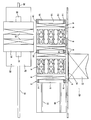
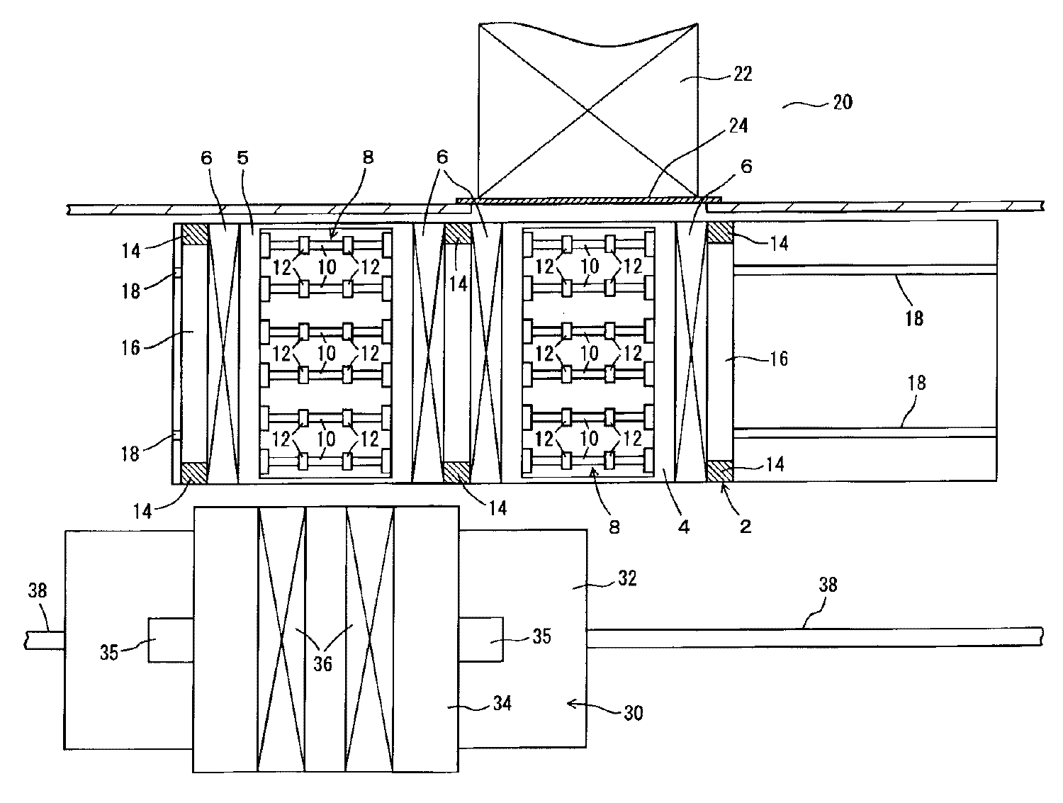
도 1은 실시예의 로더 언로더와 주위의 처리장치 및 스태커 크레인을 나타내는 일부 노치부가 있는 평면도,
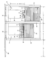
도 2는 실시예의 로더 언로더의 측면도,
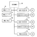
도 3은 실시예의 로더 언로더의 제어계를 나타내는 블럭도,
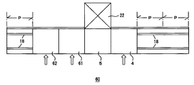
도 4는 변형예의 로더 언로더의 평면도.1 is a plan view with some notches showing the loader unloader and the surrounding processing apparatus and stacker crane of the embodiment,
2 is a side view of the loader unloader of the embodiment;
3 is a block diagram showing a control system of the loader unloader of the embodiment;
4 is a plan view of the loader unloader of the modification.
이하에 본 발명을 실시하기 위한 최적 실시예를 나타낸다. 본 발명의 범위는 특허 청구범위의 기재에 의거하여 명세서의 기재와 이 분야에서의 주지 기술을 참작하고, 당업자의 이해를 쫓아서 정해져야 한다.Best Mode for Carrying Out the Invention The following shows an optimal embodiment. The scope of the present invention should be determined based on the description of the claims, taking into consideration the description of the specification and well-known techniques in this field, and pursuing the understanding of those skilled in the art.
(실시예)(Example)
도 1∼도 4에 실시예의 로더 언로더(2)와 그 변형을 나타낸다. 도 1∼도 3에 있어서, 2는 로더 언로더이고, 4, 5는 유닛이며, 서로 물리적으로 일체적으로 연결되어 각각 리프터(6)와 롤러 컨베이어(8)를 구비하고 있다. 10은 롤러 컨베이어(8)의 롤러축이며, 12는 롤러이다. 롤러 컨베이어(8)는 로드 언로드 대상의 물품인 기판을, 예를 들면 1매씩 처리장치(20)의 로드 포트(22)와의 사이에서 주고받는다. 그것을 위해 반송 방향으로 수평면 내에서 직각인 방향을 따라 복수의 롤러축(10)을 구비하고 있다. 또한 각 롤러축(10)은 롤러(12)를 예를 들면 복수개 구비하고, 롤러(12)는 기판의 저면에 접촉해서 이송한다.1 to 4 show the
14는 로더 언로더(2)의 지주이며, 16은 대차(臺車)이고, 주행 레일(18) 상을 주행한다. 주행 레일(18)은 반송차의 예인 스태커 크레인(30)의 주행 레일(38)에 평행하게 배치되고, 반송차는 스태커 크레인(30) 이외에 유궤도 대차 또는 무인반송차 등이어도 좋다. 로더 언로더(2)는 예를 들면 클린룸 내에서 사용하므로, 도시하지 않은 커버로 덮어 클린 에어의 공급기구 등을 설치하는 것이 바람직하지만, 도시를 생략한다.14 is a support | pillar of the
20은 처리장치이고, 액정 디스플레이 패널, 플라즈마 디스플레이 패널, 태양전지판 등의 처리장치이며, 로드 포트(22)로부터 기판을 예를 들면 1매씩 로드 언로드하고, 24는 그 문이다. 또한 반송 대상의 물품은 기판에 한정되지 않고, 카세트에 수용되어서 반송되는 물품이면 된다.20 is a processing apparatus, and is processing apparatuses, such as a liquid crystal display panel, a plasma display panel, and a solar cell panel, load unloading board | substrates one by one from the
스태커 크레인(30)은 주행 레일(38)을 따라 주행한다. 32는 그 대차이다. 34는 승강대이고, 마스트(35)를 따라 승강하고, 슬라이드 포크(36)를 구비하여 카세트를 유닛(4, 5)과의 사이에서 이송한다. 또한 이송에는 슬라이드 포크(36) 대신에 스칼라 암 등을 이용하여도 좋고, 이것 이외에 카세트의 방향을 바꾸는 턴테이블 등을 설치해도 된다.The
도 2에 나타내는 바와 같이, 예를 들면 한쌍의 유닛(4, 5)에서는 리프터(6)에 의해 카세트(42)의 저부를 좌우로 지지하고, 지주(14)를 따라 승강시킨다. 이 승강 스트로크를 h라고 한다. 또한 롤러 컨베이어(8)는 예를 들면 다이(40) 위에 설치되고, 다이(40)의 높이는 승강 스트로크(h)의 정도이다. 리프터(6)의 승강에 의해 스켈리톤 형상의 카세트(42)의 내부에 롤러 컨베이어(8)가 진입하고, 롤러(12)에 의해 기판(44)을 1매씩 로드 포토와의 사이에서 이송한다. 그리고 한쌍의 유닛(4, 5)의 한쪽이 로드 포토와의 이송 위치에 있을 경우, 다른 유닛은 스태커 크레인과의 사이에서 카세트(42)를 이송하는 위치에 있고, 다이(40)의 상부의 빈 공간에 슬라이드 포크(36)가 진입하여 카세트(42)를 이송한다. 또한 롤러 컨베이어(8)을 대신하는 이송장치로서, 슬라이드 포크 또는 스칼라 암 등을 사용해도 된다. 유닛(4, 5) 사이의 피치를 P라고 하면, 로더 언로더(2)의 전체 길이는 약 2P이고, 로더 언로더(2)의 이동 스트로크는 P이다. 또한 유닛(4, 5)은 스태커 크레인의 주행경로를 따라 배치되어 있다.As shown in FIG. 2, for example, in the pair of
도 3은 로더 언로더의 컨트롤러(50)를 나타내고, 승강 드라이브(51)는 예를 들면 유닛(4)의 리프터(6)의 모터(M1)를 제어하고, 승강 드라이브(53)는 유닛(5)의 리프터의 모터(M2)를 제어한다. 컨베이어 드라이브(52)는 예를 들면 유닛(4)의 롤러 컨베이어의 구동 모터(M3)를 제어하고, 컨베이어 드라이브(54)는 유닛(5)의 롤러 컨베이어의 구동 모터를 제어한다. 주행 드라이브(55)는 대차(16)의 주행을 제어한다.3 shows the
통신 인터페이스(56)는 로드 포토와의 사이에서 통신하고, 기판을 이송할 때의 인터록을 행한다. 통신 인터페이스(57)는 스태커 크레인과의 사이에서 통신하고, 카세트를 이송할 때의 인터록을 행한다. 통신 유닛(58)은 도시하지 않은 상위 컨트롤러와의 사이에서 통신하고, 여러 가지 지령을 수신하고 실행 결과를 보고한다.The
실시예의 동작을 나타낸다. 예를 들면 도 1과 같이, 유닛(4)이 로드 포트(22)와의 사이에서 롤러 컨베이어(8)에 의해 기판을 1매씩 이송하고 있다고 한다. 이것과 동시에 스태커 크레인(30)은 슬라이드 포크(36)가 유닛(5)과 마주본 위치에서 정지하여 카세트를 이송한다. 이 결과, 한쪽의 유닛이 로드 포트(22)와의 사이에서 기판을 이송하고 있는 동안에, 다음 카세트를 다른 유닛에 적재하거나, 또는 기판을 이송 완료한 카세트를 다른 유닛으로부터 스태커 크레인에 반출할 수 있다.The operation of the embodiment is shown. For example, as shown in FIG. 1, the unit 4 conveys the board | substrate one by one by the
유닛(4, 5) 사이의 피치를 P라고 하면, 실시예에서는 2개의 유닛(4, 5)에 대하여 로더 언로더(2)의 이동 스트로크가 1피치(P)분이며, 유닛의 수-1피치만큼 이동한다. 그리고 이동 스트로크의 중앙부에 로드 포트(22)가 있다. 이 때문에 최소의 스페이스로 유닛(4, 5)을 이동시킬 수 있고, 또한 각 유닛(4, 5)은 함께 로드 포트(22)와의 사이에서 기판을 주고받는 위치로 이동할 수 있다. 또한 로더 언로더(2)에 대한 스태커 크레인(30)의 정지 위치는 유닛(4, 5)의 수와 같고, 도 1의 경우, 우측의 빈 공간이 유닛(4)과의 사이에서 카세트를 이송하는 위치가 된다.If the pitch between the
로더 언로더(2)는 카세트를 적재하는 버퍼[리프터(6)]와, 롤러 컨베이어(8)(이송장치)를 일체로 하고 있으므로 공간절약적이다. 한쌍의 유닛(4, 5)은 서로 물리적으로 연결되어 대차(16)에 의해 일체적로 이동하므로, 예를 들면 단일의 주행 모터(M5)와 단일의 주행 드라이브(55)로 이동할 수 있다.The
실시예에서는 2개의 유닛(4, 5)을 연결해서 1개의 로더 언로더(2)로 했지만, 보다 다수개의 유닛을 연결해도 좋다. 이러한 변형예를 도 4에 나타내고, 60은 새로운 로더 언로더이며, 4개의 유닛(4, 5, 61, 62)을 구비하고, 주행 스트로크의 길이는 4유닛에 대하여 3유닛만큼의 피치이고, 주행경로의 중앙부에 처리장치(20)가 있다.In the embodiment, two
이상, 본 발명의 일실시형태에 대하여 설명했지만, 본 발명은 상기 실시형태에 한정되는 것은 아니고, 발명의 요지를 일탈하지 않는 범위에서 여러 가지 변경이 가능하다. 특히, 본 명세서에 기재된 복수의 실시형태 및 변형예는 필요에 따라 임의로 조합 가능하다.As mentioned above, although one Embodiment of this invention was described, this invention is not limited to the said embodiment, A various change is possible in the range which does not deviate from the summary of invention. In particular, the plurality of embodiments and modifications described herein can be arbitrarily combined as necessary.
2 : 로더 언로더 4, 5 : 유닛
6 : 리프터 8 : 롤러 컨베이어
10 : 롤러축 12 : 롤러
14 : 지주 16 : 대차
18 : 주행 레일 20 : 처리장치
22 : 로드 포토 24 : 문
30 : 스태커 크레인 32 : 대차
34 : 승강대 35 : 마스트
36 : 슬라이드 포크 38 : 주행 레일
40 : 다이 42 : 카세트
44 : 기판 50 : 컨트롤러
51∼55 : 드라이브 56, 57 : 통신 인터페이스
58 : 통신 유닛 60 : 로더 언로더
61, 62 : 유닛 M1∼M5 : 모터
P : 피치 h : 승강 스트로크2: loader unloader 4, 5: unit
6: lifter 8: roller conveyor
10: roller shaft 12: roller
14: landlord 16: the balance
18: running rail 20: processing device
22: Road Photo 24: Moon
30: stacker crane 32: bogie
34: platform 35: mast
36: slide fork 38: travel rail
40: die 42: cassette
44: substrate 50: controller
51 to 55:
58: communication unit 60: loader unloader
61, 62: units M1 to M5: motors
P: pitch h: lifting stroke
Claims (5)
상기 카세트를 적재하는 적재부 및 상기 처리장치와의 사이에서 카세트 내의 물품을 주고받는 이송장치를 구비하고, 또한 상기 반송차의 이동경로를 따라 배치된 복수의 유닛;
상기 복수의 유닛을 상기 반송차의 이동경로를 따라 이동시키는 이동기구; 및
1개 이상의 유닛이 상기 처리장치와의 사이에서 물품을 이송하는 위치에 있을 때에 다른 1개 이상의 유닛이 상기 반송차와의 사이에서 카세트를 이송하는 위치에 있도록 상기 이동기구를 제어하는 컨트롤러를 구비하는 것을 특징으로 하는 로더 언로더.As a loader unloader which receives a cassette containing an article from a transport vehicle and exchanges the article contained in the cassette with a processing apparatus:
A plurality of units provided with a stacking unit for stacking the cassette and a transfer device for exchanging goods in the cassette between the processing apparatus and arranged along a moving path of the transport vehicle;
A moving mechanism for moving the plurality of units along a moving path of the transport vehicle; And
And a controller for controlling the moving mechanism such that the other one or more units are in a position for transferring a cassette between the transport vehicle when one or more units are in a position for transferring an article between the processing apparatus. Loader unloader, characterized in that.
상기 복수의 유닛은 서로 물리적으로 연결되어 있는 것을 특징으로 하는 로더 언로더.The method of claim 1,
The loader unloader, characterized in that the plurality of units are physically connected to each other.
상기 이동기구에 의한 상기 복수의 유닛의 이동 스트로크는 상기 유닛간의 피치의 정수배인 것을 특징으로 하는 로더 언로더.The method of claim 1,
The movement stroke of the plurality of units by the moving mechanism is an integer multiple of the pitch between the units.
상기 이동 스트로크는 상기 피치를 상기 복수의 유닛의 수-1배한 길이이며, 또한 상기 처리장치와의 사이에서 물품을 이송하는 위치가 상기 이동경로 길이의 중앙부에 배치되어 있는 것을 특징으로 하는 로더 언로더.The method of claim 3, wherein
The moving stroke is a length obtained by dividing the pitch by the number -1 times the plurality of units, and a position for transferring an article between the processing apparatus and the loader is disposed at the center of the moving path length. .
상기 로더 언로더에 상기 카세트를 적재하는 적재부 및 상기 처리장치와의 사이에서 카세트 내의 물품을 주고받는 이송장치를 구비하고, 또한 상기 반송차의 이동경로를 따라 배치된 복수의 유닛과,
상기 복수의 유닛을 상기 반송차의 이동경로를 따라 이동시키는 이동기구와,
상기 이동기구와 상기 이송장치를 제어하는 컨트롤러를 설치하고;
1개 이상의 유닛이 상기 처리장치와의 사이에서 물품을 이송하고 있을 때에 다른 1개 이상의 유닛을 상기 반송차와의 사이에서 카세트를 이송하는 위치에 배치하도록 상기 이동기구와 상기 이송장치를 상기 컨트롤러에 의해 제어하는 것을 특징으로 하는 로드 언로드 방법.A method for exchanging an article stored in a cassette with a processing device by a loader unloader with respect to a cassette conveyed from a transport vehicle:
A plurality of units provided with a loading unit for loading the cassette in the loader unloader and a transfer device for transferring an article in the cassette between the processing apparatus, and arranged along a movement path of the transport vehicle;
A moving mechanism for moving the plurality of units along a moving path of the transport vehicle,
A controller for controlling the moving mechanism and the transfer device;
When the one or more units are transferring an article between the processing apparatus, the moving mechanism and the transfer apparatus are placed on the controller so that the other one or more units are arranged in a position to transfer the cassette between the transport vehicle. Load unloading method characterized in that controlled by.
Applications Claiming Priority (2)
| Application Number | Priority Date | Filing Date | Title |
|---|---|---|---|
| JPJP-P-2009-203444 | 2009-09-03 | ||
| JP2009203444A JP2011051748A (en) | 2009-09-03 | 2009-09-03 | Loader-unloader and loading-unloading method between carrier and device |
Publications (1)
| Publication Number | Publication Date |
|---|---|
| KR20110025080A true KR20110025080A (en) | 2011-03-09 |
Family
ID=43840214
Family Applications (1)
| Application Number | Title | Priority Date | Filing Date |
|---|---|---|---|
| KR1020100078785A Ceased KR20110025080A (en) | 2009-09-03 | 2010-08-16 | Loader unloader, and how to unload the load between the van and the device |
Country Status (4)
| Country | Link |
|---|---|
| JP (1) | JP2011051748A (en) |
| KR (1) | KR20110025080A (en) |
| CN (1) | CN102009843A (en) |
| TW (1) | TW201109255A (en) |
Families Citing this family (3)
| Publication number | Priority date | Publication date | Assignee | Title |
|---|---|---|---|---|
| CN103010747B (en) * | 2011-09-21 | 2016-04-20 | 瑞世达科技(厦门)有限公司 | Transmit integrating apparatus and transfer approach thereof |
| JP6297989B2 (en) * | 2015-01-27 | 2018-03-20 | 光洋サーモシステム株式会社 | Transport device |
| CN115848862B (en) * | 2021-09-23 | 2025-02-18 | 宝山钢铁股份有限公司 | Pallet fork positioning method of stacker |
Family Cites Families (5)
| Publication number | Priority date | Publication date | Assignee | Title |
|---|---|---|---|---|
| JP3045756B2 (en) * | 1990-10-17 | 2000-05-29 | 株式会社森精機製作所 | Machine tool pallet changer |
| JP2001130708A (en) * | 1999-11-05 | 2001-05-15 | Murata Mach Ltd | Automatic warehouse system |
| CN1105672C (en) * | 2000-10-28 | 2003-04-16 | 云南昆船设计研究院 | Method and apparatus for automatized high-density warehouse |
| JP2005145713A (en) * | 2003-08-29 | 2005-06-09 | Hitachi Kiden Kogyo Ltd | Substrate transfer device |
| JP4904722B2 (en) * | 2005-06-02 | 2012-03-28 | 株式会社Ihi | Substrate transfer device |
-
2009
- 2009-09-03 JP JP2009203444A patent/JP2011051748A/en active Pending
-
2010
- 2010-08-16 KR KR1020100078785A patent/KR20110025080A/en not_active Ceased
- 2010-09-01 TW TW099129436A patent/TW201109255A/en unknown
- 2010-09-02 CN CN2010102715068A patent/CN102009843A/en active Pending
Also Published As
| Publication number | Publication date |
|---|---|
| JP2011051748A (en) | 2011-03-17 |
| CN102009843A (en) | 2011-04-13 |
| TW201109255A (en) | 2011-03-16 |
Similar Documents
| Publication | Publication Date | Title |
|---|---|---|
| CN103171850B (en) | Transhipment is arranged in the system of the goods on handling equipment | |
| CN102264613B (en) | Automated warehouse | |
| KR102405911B1 (en) | Article transport facility | |
| JP4967318B2 (en) | Stocker | |
| CN104169196B (en) | Rack storage system and method for operating the rack storage system | |
| CN107531413B (en) | Automatic warehouses and pendant stacking cranes | |
| KR102824925B1 (en) | Automated storage and retrieval system | |
| KR101414530B1 (en) | Transporting vehicle system | |
| WO2016031351A1 (en) | Picking system and picking method | |
| CN110683269A (en) | Warehousing system | |
| KR20040070427A (en) | Overhead traveling vehicle system | |
| JP4470576B2 (en) | Transport system | |
| CN211768039U (en) | Warehousing system | |
| JP4756371B2 (en) | Goods storage equipment | |
| KR101398929B1 (en) | Transporting vehicle system | |
| US7806648B2 (en) | Transportation system and transportation method | |
| JP2018070295A (en) | Suspension type stacker crane | |
| JP2019006517A (en) | Package delivery system | |
| KR20110025080A (en) | Loader unloader, and how to unload the load between the van and the device | |
| CN217731544U (en) | Conveying and storing device | |
| JP2004238191A (en) | Ceiling travel vehicle system | |
| JP2010235212A (en) | Traveling vehicle system | |
| JP2008019017A (en) | Article storage device | |
| JP2017088316A (en) | Automatic warehouse system | |
| JP2010235213A (en) | Traveling vehicle system |
Legal Events
| Date | Code | Title | Description |
|---|---|---|---|
| PA0109 | Patent application |
St.27 status event code: A-0-1-A10-A12-nap-PA0109 |
|
| R18-X000 | Changes to party contact information recorded |
St.27 status event code: A-3-3-R10-R18-oth-X000 |
|
| PG1501 | Laying open of application |
St.27 status event code: A-1-1-Q10-Q12-nap-PG1501 |
|
| A201 | Request for examination | ||
| PA0201 | Request for examination |
St.27 status event code: A-1-2-D10-D11-exm-PA0201 |
|
| E902 | Notification of reason for refusal | ||
| PE0902 | Notice of grounds for rejection |
St.27 status event code: A-1-2-D10-D21-exm-PE0902 |
|
| E601 | Decision to refuse application | ||
| PE0601 | Decision on rejection of patent |
St.27 status event code: N-2-6-B10-B15-exm-PE0601 |
|
| P22-X000 | Classification modified |
St.27 status event code: A-2-2-P10-P22-nap-X000 |