KR20100085820A - Construction machine - Google Patents
Construction machine Download PDFInfo
- Publication number
- KR20100085820A KR20100085820A KR1020090095380A KR20090095380A KR20100085820A KR 20100085820 A KR20100085820 A KR 20100085820A KR 1020090095380 A KR1020090095380 A KR 1020090095380A KR 20090095380 A KR20090095380 A KR 20090095380A KR 20100085820 A KR20100085820 A KR 20100085820A
- Authority
- KR
- South Korea
- Prior art keywords
- heat exchanger
- frame
- engine
- utility room
- box
- Prior art date
- Legal status (The legal status is an assumption and is not a legal conclusion. Google has not performed a legal analysis and makes no representation as to the accuracy of the status listed.)
- Withdrawn
Links
- 238000010276 construction Methods 0.000 title claims description 15
- 238000001816 cooling Methods 0.000 claims description 33
- 239000012530 fluid Substances 0.000 claims description 13
- 239000012809 cooling fluid Substances 0.000 claims 1
- 238000005192 partition Methods 0.000 abstract description 10
- 239000003921 oil Substances 0.000 description 18
- 239000004519 grease Substances 0.000 description 10
- 238000012423 maintenance Methods 0.000 description 7
- 239000010720 hydraulic oil Substances 0.000 description 5
- 239000004744 fabric Substances 0.000 description 3
- 238000009412 basement excavation Methods 0.000 description 2
- 239000002826 coolant Substances 0.000 description 2
- 230000004308 accommodation Effects 0.000 description 1
- 238000004140 cleaning Methods 0.000 description 1
- 239000000498 cooling water Substances 0.000 description 1
- 230000002349 favourable effect Effects 0.000 description 1
- 239000002828 fuel tank Substances 0.000 description 1
- 238000007689 inspection Methods 0.000 description 1
- 239000004576 sand Substances 0.000 description 1
Images


Classifications
-
- E—FIXED CONSTRUCTIONS
- E02—HYDRAULIC ENGINEERING; FOUNDATIONS; SOIL SHIFTING
- E02F—DREDGING; SOIL-SHIFTING
- E02F9/00—Component parts of dredgers or soil-shifting machines, not restricted to one of the kinds covered by groups E02F3/00 - E02F7/00
- E02F9/08—Superstructures; Supports for superstructures
- E02F9/0858—Arrangement of component parts installed on superstructures not otherwise provided for, e.g. electric components, fenders, air-conditioning units
- E02F9/0866—Engine compartment, e.g. heat exchangers, exhaust filters, cooling devices, silencers, mufflers, position of hydraulic pumps in the engine compartment
-
- B—PERFORMING OPERATIONS; TRANSPORTING
- B60—VEHICLES IN GENERAL
- B60Y—INDEXING SCHEME RELATING TO ASPECTS CROSS-CUTTING VEHICLE TECHNOLOGY
- B60Y2200/00—Type of vehicle
- B60Y2200/40—Special vehicles
- B60Y2200/41—Construction vehicles, e.g. graders, excavators
- B60Y2200/412—Excavators
-
- F—MECHANICAL ENGINEERING; LIGHTING; HEATING; WEAPONS; BLASTING
- F01—MACHINES OR ENGINES IN GENERAL; ENGINE PLANTS IN GENERAL; STEAM ENGINES
- F01P—COOLING OF MACHINES OR ENGINES IN GENERAL; COOLING OF INTERNAL-COMBUSTION ENGINES
- F01P11/00—Component parts, details, or accessories not provided for in, or of interest apart from, groups F01P1/00 - F01P9/00
- F01P11/10—Guiding or ducting cooling-air, to, or from, liquid-to-air heat exchangers
-
- F—MECHANICAL ENGINEERING; LIGHTING; HEATING; WEAPONS; BLASTING
- F01—MACHINES OR ENGINES IN GENERAL; ENGINE PLANTS IN GENERAL; STEAM ENGINES
- F01P—COOLING OF MACHINES OR ENGINES IN GENERAL; COOLING OF INTERNAL-COMBUSTION ENGINES
- F01P5/00—Pumping cooling-air or liquid coolants
- F01P5/02—Pumping cooling-air; Arrangements of cooling-air pumps, e.g. fans or blowers
-
- F—MECHANICAL ENGINEERING; LIGHTING; HEATING; WEAPONS; BLASTING
- F04—POSITIVE - DISPLACEMENT MACHINES FOR LIQUIDS; PUMPS FOR LIQUIDS OR ELASTIC FLUIDS
- F04D—NON-POSITIVE-DISPLACEMENT PUMPS
- F04D29/00—Details, component parts, or accessories
- F04D29/58—Cooling; Heating; Diminishing heat transfer
- F04D29/5806—Cooling the drive system
Landscapes
- Engineering & Computer Science (AREA)
- Mining & Mineral Resources (AREA)
- Civil Engineering (AREA)
- General Engineering & Computer Science (AREA)
- Structural Engineering (AREA)
- Component Parts Of Construction Machinery (AREA)
- Cooling, Air Intake And Gas Exhaust, And Fuel Tank Arrangements In Propulsion Units (AREA)
Abstract
본 발명의 과제는, 새로운 부품을 설치하는 일 없이 프레임 상에 유틸리티실을 설치함으로써, 차체를 조립할 때의 작업성을 향상시키는 것이다.An object of the present invention is to improve workability when assembling a vehicle body by providing a utility room on a frame without installing new parts.
제1 열교환 장치(21)를 선회 프레임(6)의 좌측으로 치우쳐서 배치하고, 제2 열교환 장치(25)를 선회 프레임(6)의 좌측으로 치우치게 하고, 또한 제1 열교환 장치(21)의 전방측에 간극을 갖고 배치한다. 이에 의해, 제1 열교환 장치(21)와 제2 열교환 장치(25) 사이의 전후 방향의 공간을 이용하여 유틸리티실(32)을 설치할 수 있다. 따라서, 유틸리티실(32)은 기존의 제1 열교환 장치(21), 제2 열교환 장치(25)를 전후 방향의 구획면으로서 이용하여 형성할 수 있으므로, 유틸리티실(32)은 새롭게 구획판 등을 추가하는 일 없이, 선회 프레임(6) 상에 간단하게 형성할 수 있다.The first heat exchanger 21 is arranged to the left of the swing frame 6, the second heat exchanger 25 is to the left of the swing frame 6, and the front side of the first heat exchanger 21 is also located. Position it with a gap in it. Thereby, the utility room 32 can be provided using the space of the front-back direction between the 1st heat exchanger 21 and the 2nd heat exchanger 25. As shown in FIG. Therefore, since the utility room 32 can be formed using the existing 1st heat exchanger 21 and the 2nd heat exchanger 25 as a partition surface of a front-back direction, the utility room 32 newly installs a partition plate etc. It can form easily on the turning frame 6, without adding.
Description
본 발명은, 예를 들어 유압 셔블, 유압 크레인 등으로서 적절하게 사용되는 건설 기계에 관한 것이다.TECHNICAL FIELD This invention relates to the construction machine used suitably as a hydraulic excavator, a hydraulic crane, etc., for example.
일반적으로, 건설 기계로서의 유압 셔블은, 자주 가능한 하부 주행체와, 상기 하부 주행체 상에 선회 가능하게 탑재된 상부 선회체와, 상기 상부 선회체의 전방측으로 부앙(俯仰) 이동 가능하게 설치된 작업 장치에 의해 구성되어 있다.Background Art Generally, a hydraulic excavator as a construction machine includes a lower traveling body that is frequently possible, an upper swinging body that is pivotally mounted on the lower traveling body, and a work device provided to be movable in a forward direction of the upper swinging body. It consists of.
또한, 상부 선회체는 지지 구조체를 이루는 선회 프레임과, 상기 선회 프레임의 전방측에 설치되어 오퍼레이터가 탑승하는 캡과, 상기 선회 프레임의 후방측에 탑재되어 유압 펌프를 구동하는 엔진과, 상기 엔진을 사이에 두고 상기 유압 펌프의 반대측에 배치된 열교환 장치를 구비하고 있다.The upper swing structure includes a swing frame constituting the support structure, a cap installed at the front side of the swing frame and mounted by an operator, an engine mounted on the rear side of the swing frame to drive a hydraulic pump, and the engine. It is provided with the heat exchanger arrange | positioned on the opposite side to the said hydraulic pump in between.
그리고, 열교환 장치는, 예를 들어 엔진에 의해 회전 구동되는 냉각 팬과, 상기 냉각 팬에 대면하여 설치된 엔진 냉각수를 냉각하는 라디에이터, 작동유를 냉각하는 오일쿨러, 과급기에 의해 온도 상승(팽창)한 흡기를 냉각(수축)하는 인터쿨러 등의 열교환기에 의해 구성되어 있다.The heat exchanger includes, for example, a cooling fan that is rotationally driven by the engine, a radiator for cooling the engine cooling water provided to face the cooling fan, an oil cooler for cooling the working oil, and an air intake that has risen (expanded) by a supercharger. It is comprised by heat exchangers, such as an intercooler which cools (contracts).
또한, 유압 셔블은 고온의 환경에서 작업하거나, 지나치게 사용한 경우, 1개 의 냉각 팬만으로는, 라디에이터와 인터쿨러와 오일쿨러의 3개의 열교환기를 흐르는 유체를 효율적으로 냉각할 수 없게 될 우려가 있다.In addition, when the hydraulic excavator works in a high temperature environment or is excessively used, only one cooling fan may not be able to efficiently cool the fluid flowing through the three heat exchangers of the radiator, the intercooler, and the oil cooler.
따라서, 유압 셔블에는 라디에이터와 인터쿨러와 이들에 냉각풍을 공급하는 엔진의 냉각 팬에 의해 제1 열교환 장치를 구성하고, 한편, 오일쿨러와 상기 오일쿨러에 냉각풍을 공급하기 위해 모터에 구동되는 냉각 팬에 의해 제2 열교환 장치를 구성하고, 이 2개의 열교환 장치를 선회 프레임 상에 설치하는 구성으로 한 것이 있다(예를 들어, 특허 문헌 1 참조).Therefore, in the hydraulic excavator, the first heat exchanger is constituted by a radiator, an intercooler, and a cooling fan of an engine for supplying cooling air to them, while cooling driven by a motor to supply cooling air to the oil cooler and the oil cooler. There exists a structure which comprises a 2nd heat exchanger apparatus by a fan, and sets these two heat exchanger apparatuses on a revolving frame (for example, refer patent document 1).
이 유압 셔블의 경우, 엔진은 선회 프레임의 후방측에 횡치 상태로 탑재되고, 제1 열교환 장치는, 예를 들어 엔진의 좌측에 배치되어 있다. 또한, 제2 열교환 장치는 제1 열교환 장치의 전방측에 배치되어 있다.In the case of this hydraulic excavator, the engine is mounted on the rear side of the swing frame in a transverse state, and the first heat exchanger is disposed on the left side of the engine, for example. In addition, the second heat exchanger is disposed at the front side of the first heat exchanger.
[특허 문헌 1] 일본 특허 출원 공개 제2000-130161호 공보[Patent Document 1] Japanese Patent Application Laid-Open No. 2000-130161
그런데, 상술한 종래 기술에 의한 유압 셔블에서는 그리스 등의 소모품, 메인터넌스용 공구 등을 수용하기 위한 유틸리티실이 설치된다. 그러나, 유틸리티실을 설치하는 경우에는, 다목적인 수용 스페이스를 형성하기 위해 구획판 등을 새롭게 설치해야만 한다. 따라서, 유틸리티실을 형성하는 구획판 등의 부품이 증가하게 되어, 조립 작업성이 저하된다고 하는 문제가 있다.By the way, in the above-mentioned conventional hydraulic excavator, a utility room for accommodating consumables such as grease, maintenance tools, and the like is provided. However, when installing a utility room, a partition plate etc. must be newly provided in order to form a multipurpose accommodation space. Therefore, there exists a problem that components, such as a partition plate which forms a utility room, increase, and assembly workability falls.
본 발명은 상술한 종래 기술의 문제에 비추어 이루어진 것으로, 본 발명의 목적은 새로운 부품을 설치하는 일 없이 프레임 상에 유틸리티실을 설치할 수 있어, 조립 작업성을 향상시킬 수 있도록 한 건설 기계를 제공하는 데 있다.The present invention has been made in view of the above-described problems of the prior art, and an object of the present invention is to provide a construction machine that can install a utility room on a frame without installing new parts, thereby improving assembly workability. There is.
본 발명에 의한 건설 기계는, 차체의 지지 구조체를 형성하는 프레임과, 상기 프레임에 탑재되어 유압 펌프를 구동하는 엔진과, 상기 엔진의 근방에 위치하여 상기 프레임에 설치되어 상기 엔진에 구동되는 냉각 팬에 의해 가열된 유체를 냉각하는 제1 열교환 장치와, 상기 프레임에 상기 제1 열교환 장치와는 별개로 설치되어 구동 모터에 구동되는 냉각 팬에 의해 가열된 유체를 냉각하는 제2 열교환 장치와, 상기 엔진, 제1 열교환 장치, 제2 열교환 장치를 덮어서 설치된 본체 커버를 구비하고 있다.The construction machine according to the present invention includes a frame forming a support structure of a vehicle body, an engine mounted on the frame to drive a hydraulic pump, and a cooling fan installed in the frame and located in the vicinity of the engine to drive the engine. A first heat exchanger for cooling the fluid heated by the second heat exchanger, a second heat exchanger for cooling the fluid heated by a cooling fan driven separately from the first heat exchanger and driven by a drive motor in the frame; A main body cover provided covering the engine, the first heat exchanger, and the second heat exchanger is provided.
그리고, 상술한 과제를 해결하기 위해, 청구항 1의 발명이 채용하는 구성의 특징은, 상기 제1 열교환 장치는 상기 프레임에 대해 좌우 방향의 일측으로 치우쳐 서 배치되고, 상기 제2 열교환 장치는 상기 프레임에 대해 좌우 방향의 일측이고, 또한 상기 제1 열교환 장치에는 전후 방향으로 간극을 갖고 배치되고, 상기 제1 열교환 장치와 제2 열교환 장치 사이에 형성된 전후 방향의 공간을 유틸리티실로서 형성하는 구성으로 한 것에 있다.And, in order to solve the above-mentioned problems, the feature of the structure employed by the invention of
청구항 2의 발명은, 상기 제1, 제2 열교환 장치는, 적어도 전방면판, 후방면판, 상면판을 사용하여 상자 형상으로 형성된 상자체와, 상기 상자체 내에 수용되어 냉각되어야 할 유체가 유통하는 열교환기에 의해 구성하고, 상기 유틸리티실은 상기 제1 열교환 장치의 상자체와 제2 열교환 장치의 상자체 사이에 형성되는 공간으로 한 것에 있다.The invention according to
청구항 3의 발명은, 상기 유틸리티실에는 그 하측을 폐색하는 저면판을 설치하는 구성으로 한 것에 있다.According to a third aspect of the present invention, there is provided a bottom plate in which the lower side of the utility room is closed.
청구항 4의 발명은, 상기 유틸리티실은 상기 본체 커버의 측면 도어에 의해 개폐되는 구성으로 한 것에 있다.According to a fourth aspect of the present invention, the utility room is configured to be opened and closed by a side door of the main body cover.
청구항 5의 발명은, 상기 프레임은 저판과, 상기 저판 상에 전후 방향으로 연장되어 설치된 좌우의 종판과, 상기 좌우의 종판으로부터 좌우 방향으로 돌출되어 설치된 좌우의 돌출 빔과, 상기 좌우의 돌출 빔의 돌출 단부측에 전후 방향으로 연장되어 설치된 좌우의 사이드 프레임에 의해 구성되고, 상기 엔진은 상기 좌우의 종판을 걸쳐서 좌우 방향으로 배치되고, 상기 제1 열교환 장치는 좌우 방향의 일측의 종판과 일측의 사이드 프레임 사이에 상기 엔진과 직렬로 배열하여 배치되고, 상기 제2 열교환 장치는 좌우 방향의 일측의 종판과 일측의 사이드 프레임 사이이 고, 또한 제1 열교환 장치의 전방측에 간극을 갖고 배치되고, 상기 유틸리티실은 상기 제1 열교환 장치의 전방면과 제2 열교환 장치의 후방면 사이에 형성되는 구성으로 한 것에 있다.According to the invention of
청구항 1의 발명에 따르면, 제2 열교환 장치를, 제1 열교환 장치의 전후 방향에 간극을 갖고 배치함으로써, 제1 열교환 장치와 제2 열교환 장치 사이에 형성된 전후 방향의 공간을 물품이 수용 가능한 유틸리티실로서 형성할 수 있다.According to the invention of
이 결과, 새롭게 구획판 등의 다른 부품을 추가하는 일 없이, 프레임 상에 유틸리티실을 용이하게 형성할 수 있으므로, 부품의 증대를 억제하여 조립 작업성을 향상시킬 수 있다.As a result, the utility room can be easily formed on the frame without newly adding another component such as a partition plate, so that the increase in parts can be suppressed and the assembly workability can be improved.
청구항 2의 발명에 따르면, 전방면판, 후방면판, 상면판을 사용하여 상자 형상으로 형성된 상자체 내에 열교환기를 수용하여 이루어지는 제1, 제2 열교환 장치는, 제1 열교환 장치의 상자체의 전방면판과 제2 열교환 장치의 상자체의 후방면판 사이에 공간을 형성할 수 있고, 이 공간을 유틸리티실로서 사용할 수 있다.According to the invention of
청구항 3의 발명에 따르면, 유틸리티실의 하측을 폐색하는 저면판을 설치함으로써, 이 저면판 상에 그리스 등의 소모품, 메인터넌스용 공구 등을 적재하여 수용할 수 있다.According to the invention of
청구항 4의 발명에 따르면, 본체 커버의 측면 도어를 개방함으로써, 유틸리티실을 개방할 수 있고, 그리스 등의 소모품, 메인터넌스용 공구 등을 출입할 수 있다.According to the invention of
청구항 5의 발명에 따르면, 좌우 방향의 일측의 종판과 일측의 사이드 프레임 사이의 스페이스를 이용하여, 제1 열교환 장치, 제2 열교환 장치 및 유틸리티실을 설치할 수 있다.According to invention of
이하, 본 발명의 실시 형태에 관한 건설 기계로서, 크롤러식 유압 셔블을 예로 들어, 도 1 내지 도 10에 따라서 상세하게 설명한다.EMBODIMENT OF THE INVENTION Hereinafter, as a construction machine which concerns on embodiment of this invention, a crawler type hydraulic excavator is taken as an example and it demonstrates in detail according to FIGS.
도 1, 도 2에 있어서, 부호 1은 건설 기계로서의 크롤러식 유압 셔블이고, 상기 유압 셔블(1)은 자주 가능한 하부 주행체(2)와, 상기 하부 주행체(2) 상에 선회 장치(3)를 통해 선회 가능하게 탑재되어, 상기 하부 주행체(2)와 함께 차체를 구성하는 상부 선회체(4)와, 상기 상부 선회체(4)의 전방측에 부앙 이동 가능하게 설치되어, 토사의 굴착 작업 등을 행하는 작업 장치(5)에 의해 대략 구성되어 있다.In FIG. 1, 2, the code |
부호 6은 상부 선회체(4)의 선회 프레임이다. 이 선회 프레임(6)은 지지 구조체로 이루어지는 차체 프레임으로서 구성되어 있다. 그리고, 선회 프레임(6)은, 도 3, 도 4 등에 도시한 바와 같이 전후 방향으로 연장되는 두꺼운 평판으로 이루어져 선회 장치(3)가 설치되는 저판(7)과, 좌우 방향으로 소정의 간격을 갖고 상기 저판(7) 상에 세워서 설치되어 전후 방향으로 연장된 좌측 종판(8), 우측 종판(9)과, 상기 좌측 종판(8)으로부터 좌측으로 돌출되어 설치된 복수의 좌측 돌출 빔(10)과, 상기 우측 종판(9)으로부터 우측으로 돌출되어 설치된 복수의 우측 돌출 빔(11)과, 상기 각 좌측 돌출 빔(10)의 돌출 단부측에 고착되어 전후 방향으로 연 장된 단면 D형의 좌측 사이드 프레임(12)과, 상기 각 우측 돌출 빔(11)의 돌출 단부측에 고착되어 전후 방향으로 연장된 단면 D형의 우측 사이드 프레임(13)과, 좌측 종판(8)의 좌측에 위치하여 저판(7)과 좌측 사이드 프레임(12)의 좌측 전방부측에 설치된 캡 지지부(14)에 의해 견고한 지지 구조체로서 구성되어 있다.
여기서, 좌측 돌출 빔(10)은 전방측으로부터 후방측에 걸쳐서 원하는 간격을 갖고 배치된 5개의 좌측 돌출 빔(10A 내지 10E)에 의해 구성되어 있다. 또한, 우측 돌출 빔(11)은 전방측으로부터 후방측에 걸쳐서 원하는 간격을 갖고 배치된 5개의 우측 돌출 빔(11A 내지 11E)에 의해 구성되어 있다.Here, the left
또한, 선회 프레임(6)에는, 예를 들어 전방측으로부터 2번째의 좌측 돌출 빔(10B)과 3번째의 좌측 돌출 빔(10C) 사이에 전후 방향으로 연장되어 2개의 빔 부재(10F)가 설치되고, 전방측으로부터 4번째의 좌측 돌출 빔(10D)과 최후방부의 좌측 돌출 빔(10E) 사이에 전후 방향으로 연장되어 1개의 빔 부재(10G)가 설치되어 있다. 그리고, 전후 방향의 중간부에 위치하는 2개의 빔 부재(10F)에는 후술하는 제2 열교환 장치(25)가 설치되고, 후방측의 빔 부재(10G)에는 후술하는 제1 열교환 장치(21)가 설치된다.In the swinging
또한, 좌우의 종판(8, 9)의 전방측 위치에는 작업 장치(5)가 설치되고, 후방측 위치에는 후술하는 엔진(17)이 탑재되어 있다. 또한, 캡 지지부(14) 상에는 캡(15)이 탑재되어 있다.Moreover, the
다음에, 상술한 바와 같이 구성된 선회 프레임(6)에 탑재되는 각종 기기류에 대해 설명한다.Next, various devices mounted on the
우선, 부호 15는 선회 프레임(6)의 좌측 전방측에 위치하는 캡 지지부(14)에 탑재된 캡이다. 이 캡(15)은 오퍼레이터가 탑승하는 것으로, 그 내부에는 오퍼레이터가 착석하는 운전석, 주행용 조작 레버, 작업용 조작 레버 등(모두 도시하지 않음)이 배치되어 있다.First, the code |
부호 16은 선회 프레임(6)의 후방부에 설치된 카운터 웨이트이다. 이 카운터 웨이트(16)는 작업 장치(5)와의 중량 균형을 잡는 것으로, 좌우의 종판(8, 9)의 후단부에 설치되어 있다.
부호 17은 카운터 웨이트(16)의 전방측에 위치하여 선회 프레임(6)의 후방부에 설치된 엔진을 나타내고 있다(도 3 참조). 이 엔진(17)은 좌우의 종판(8, 9)을 걸치도록 횡치 상태로 좌우의 종판(8, 9)의 후방측 위치에 방진 상태로 탑재되어 있다. 또한, 엔진(17)의 좌측에는 당해 엔진(17)에 의해 회전 구동하는 엔진 구동식 냉각 팬(17A)이 설치되어 있다.
한편, 엔진(17)에는, 예를 들어 흡기의 유량을 증대시키는 과급기(17B)(터보 과급기)가 설치되고, 상기 과급기(17B)는 후술하는 제1 열교환 장치(21)의 인터쿨러(24)에 접속되어 있다. 또한, 엔진(17)의 우측에는 작업 장치(5)의 액추에이터 등에 압유를 공급하기 위한 유압 펌프(18)가 설치되어 있다.On the other hand, the
부호 19는 유압 펌프(18)의 전방측에 위치하여 선회 프레임(6)의 우측 종판(9)의 우측에 탑재된 작동유 탱크, 부호 20은 상기 작동유 탱크(19)의 전방측에 인접하여 배치된 연료 탱크를 각각 나타내고 있다.19 is a hydraulic oil tank located on the front side of the
다음에, 유압 셔블(1)에서 사용하는 유체가 가열되었을 때에, 이 유체를 냉 각하기 위해 설치된 2개의 열교환 장치에 대해 설명한다.Next, when the fluid used by the
부호 21은 선회 프레임(6) 상에 위치하여 엔진(17)의 좌측에 직렬로 배열하여 설치된 제1 열교환 장치를 나타내고 있다(도 3 참조). 이 제1 열교환 장치(21)는 냉각해야 할 유체가 되는 엔진(17)에 의해 가열된 엔진 냉각수, 과급기(17B)에 의해 가열된 흡기(흡입 공기)의 열교환을 행하여 이들을 냉각하는 것이다. 그리고, 제1 열교환 장치(21)는, 도 7, 도 8에 도시한 바와 같이 후술하는 상자체(22), 라디에이터(23), 인터쿨러(24) 등에 의해 대략 구성되어 있다.
부호 22는 제1 열교환 장치(21)의 외형을 구성하는 상자체이고, 상기 상자체(22)는 후술하는 라디에이터(23)와 인터쿨러(24)를 냉각풍의 흐름 방향이 좌우 방향으로 되도록 둘러싸는 것이다. 구체적으로 상자체(22)는 선회 프레임(6)의 좌우 방향으로 연장되면서 수직 상승한 전방면판(22A)과, 상기 전방면판(22A)으로부터 후방측으로 소정 치수 이격된 위치에서 상기 전방면판(22A)과 대략 평행하게 설치된 후방면판(22B)과, 상기 전방면판(22A)의 상부와 후방면판(22B)의 상부 사이를 전후 방향으로 연장되어 연결하는 상면판(22C)과, 상기 전방면판(22A), 후방면판(22B), 상면판(22C)의 엔진(17)측이 되는 우측에 설치된 우측면판(22D)에 의해 상자체 형상으로 형성되어 있다. 또한, 우측면판(22D)에는 엔진(17)의 냉각 팬(17A)을 수납하기 위한 팬 슈라우드(22E)가 개방되어 형성되어 있다. 그리고, 상자체(22)는, 도 5, 도 6에 도시한 바와 같이, 후방측에 위치하는 좌측 돌출 빔(10D, 10E), 빔 부재(10G)에 대해 볼트 고정되어 있다.
부호 23은 상자체(22) 내에 냉각 팬(17A)과 대면하도록 설치된 열교환기로서 의 라디에이터이고, 상기 라디에이터(23)는 상자체(22) 내의 전방측 근처에 배치되어 있다. 또한, 라디에이터(23)는 가열된 엔진 냉각수를 냉각하는 것으로, 엔진(17)의 워크 재킷에 접속되어 있다.
부호 24는 상자체(22) 내에 위치하여 라디에이터(23)의 후방측에 병렬로 배치된 열교환기로서의 인터쿨러이다. 이 인터쿨러(24)는 과급기(17B)를 통해 온도 상승(팽창)한 흡기를 냉각(수축)하여 엔진(17)으로 복귀시키는 것이다. 이 인터쿨러(24)는 과급기(17B)와 엔진(17)의 흡기측에 접속되어 있다.
여기서, 제1 열교환 장치(21)는 선회 프레임(6)에 대해 좌우 방향의 일측이 되는 좌측으로 치우침으로써, 좌측 종판(8)과 좌측 사이드 프레임(12) 사이에 엔진(17)과 직렬로 배열하여 배치되어 있다. 그리고, 제1 열교환 장치(21)는 엔진(17)의 냉각 팬(17A)을 회전 구동함으로써, 본체 커버(30)의 외부로부터 냉각풍을 흡입하여 상자체(22) 내의 라디에이터(23), 인터쿨러(24)에 공급하여, 각각을 흐르는 유체를 냉각할 수 있다.Here, the
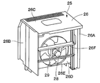
부호 25는 제1 열교환 장치(21)와는 별개로 선회 프레임(6) 상에 설치된 제2 열교환 장치를 나타내고 있다. 이 열교환 장치(25)는 좌측 종판(8)과 좌측 사이드 프레임(12) 사이이고, 또한 제1 열교환 장치(21)의 전방측에 큰 간극(A)(도 3, 도 5 참조)을 갖고 배치되어 있다. 이 경우, 제2 열교환 장치(25)는 캡(15)의 후방면측에 인접하여 배치되어, 간극(A)을 가급적 크게 취하도록 되어 있다. 이에 의해, 제2 열교환 장치(25)와 제1 열교환 장치(21) 사이에는 후술하는 유틸리티실(32)이 형성되어 있다. 또한, 제2 열교환 장치(25)는 냉각해야 할 유체가 되는 가열된 작 동유의 열교환을 행하여 냉각하는 것이다. 그리고, 제2 열교환 장치(25)는, 도 9, 도 10에 도시한 바와 같이, 후술하는 상자체(26), 오일쿨러(27) 등에 의해 대략 구성되어 있다.
부호 26은 제2 열교환 장치(25)의 외형을 구성하는 상자체이다. 이 상자체(26)는 제1 열교환 장치(21)의 상자체(22)와 대략 마찬가지로, 후술하는 오일쿨러(27)를 냉각풍의 흐름 방향이 좌우 방향이 되도록 둘러싸는 것으로, 전방면판(26A), 후방면판(26B), 상면판(26C), 우측면판(26D)에 의해 상자체 형상으로 형성되고, 그 우측면판(26D)에는 팬 슈라우드(26E)가 개방되어 형성되어 있다. 한편, 상자체(26)에는 우측면판(26D)의 외측(우측)에 위치하여 전방면판(26A)과 후방면판(26B)에 모터 설치 프레임(26F)이 설치되어 있다. 그리고, 상자체(26)는, 도 5, 도 6에 도시한 바와 같이 중간부에 위치하는 좌측 돌출 빔(10B, 10C), 각 빔 부재(10F)에 대해 볼트 고정되어 있다.
부호 27은 상자체(26) 내에 전후 방향으로 연장되어 설치된 열교환기로서의 오일쿨러이고, 상기 오일쿨러(27)는 상자체(26) 내의 전방측 근처에 배치되어 있다. 또한, 오일쿨러(27)는 하부 주행체(2), 선회 장치(3), 작업 장치(5) 등의 액추에이터로부터 작동유 탱크(19)로 복귀되는 고온의 작동유를 냉각하는 것이다.
부호 28은 모터 설치 프레임(26F)에 설치된 전동 모터, 유압 모터 등의 구동 모터이다. 또한, 부호 29는 오일쿨러(27)의 우측에 대면하여 설치된 모터 구동식 냉각 팬을 나타내고 있다. 이 냉각 팬(29)은 구동 모터(28)의 회전축에 설치되어, 팬 슈라우드(26E) 내에서 회전 구동됨으로써, 오일쿨러(27)에 냉각풍을 공급하는 것이다.
여기서, 제2 열교환 장치(25)는 캡(15)의 후방면측의 위치, 즉 선회 프레임(6)에 대해 좌우 방향의 일측이 되는 좌측으로 치우침으로써, 좌측 종판(8)과 좌측 사이드 프레임(12) 사이에서 캡(15)의 후방면측에 인접하는 위치에 배치되어 있다. 따라서, 제2 열교환 장치(25)는 제1 열교환 장치(21)와 이격하여 배치할 수 있고, 상기 제1 열교환 장치(21)의 전방측에 큰 간극(A)을 확보할 수 있다. 이 간극(A)은 제1 열교환 장치(21)를 구성하는 상자체(22)의 전방면판(22A)과 제2 열교환 장치(25)를 구성하는 상자체(26)의 후방면판(26B) 사이에, 예를 들어 그리스, 헝겊 등의 소모품, 각종 스패너, 그리스 건 등의 메인터넌스용 공구 등의 일부 또는 대부분을 수용 가능한 공간을 확보할 수 있는 치수로 되어 있다.Here, the
그리고, 제2 열교환 장치(25)는 구동 모터(28)에 의해 냉각 팬(29)을 회전 구동함으로써, 본체 커버(30)의 외부로부터 냉각풍을 흡입하여 상자체(26) 내의 오일쿨러(27)에 공급하여, 이 오일쿨러(27)를 흐르는 작동유를 냉각할 수 있다.Then, the
부호 30은 캡(15)과 카운터 웨이트(16) 사이에 위치하여 선회 프레임(6) 상에 설치된 본체 커버이다(도 1, 도 2 참조). 이 본체 커버(30)는 엔진(17), 유압 펌프(18), 제1 열교환 장치(21), 제2 열교환 장치(25) 등을 덮는 것이다. 또한, 본체 커버(30)는 각 열교환 장치(21, 25) 등의 상측을 덮는 상면 커버(30A)와, 상부 선회체(4)의 좌측면부를 형성하는 전후의 좌측면 도어(30B, 30C)와, 상부 선회체(4)의 우측면부를 형성하는 우측면 도어(도시하지 않음)와, 상기 상면 커버(30A) 상에 개폐 가능하게 설치되어, 엔진(17)의 상부를 덮는 엔진 커버(30D)에 의해 대 략 구성되어 있다.
여기서, 전후의 좌측면 도어(30B, 30C)는, 도 2에 도시한 바와 같이 제1 열교환 장치(21), 제2 열교환 장치(25)의 청소, 점검, 수리 등의 메인터넌스 작업을 행할 때에 개방되는 것이다. 또한, 좌측면 도어(30B, 30C)를 개방한 상태에서는, 후술하는 유틸리티실(32)을 외부로 개방할 수 있어, 상기 유틸리티실(32)에 대해 물품의 출입을 행할 수 있다.Here, the front and rear
부호 31은 제1 열교환 장치(21)와 제2 열교환 장치(25) 사이에 위치하여 선회 프레임(6)에 설치된 저면판이다. 이 저면판(31)은 후술하는 유틸리티실(32)의 하측을 폐색하는 것으로, 소모품이나 공구류를 적재할 수 있다. 또한, 저면판(31)은, 도 6에 도시한 바와 같이, 예를 들어 대략 직사각 형상의 평판으로 이루어지고, 전방측으로부터 3번째의 좌측 돌출 빔(10C)과 4번째의 좌측 돌출 빔(10D)에 볼트 고정되어 있다.
다음에, 상부 선회체(4)에 그리스, 헝겊 등의 소모품, 각종 스패너, 그리스 건 등의 메인터넌스용 공구를 수용하기 위한 다목적 유틸리티실(32)에 대해, 도 2, 도 3, 도 5 등을 참조하여 설명한다.Next, FIG. 2, FIG. 3, FIG. 5, and the like, of the
도 2에 있어서, 부호 32는 상부 선회체(4)의 좌측에 위치하여 제1 열교환 장치(21)와 제2 열교환 장치(25) 사이에 설치된 유틸리티실을 나타내고 있다. 이 유틸리티실(32)은 제1 열교환 장치(21)를 구성하는 상자체(22)의 전방면판(22A)과 제2 열교환 장치(25)를 구성하는 상자체(26)의 후방면판(26B) 사이에 형성된 전후 방향의 공간에 의해 구성되어 있다. 또한, 유틸리티실(32)은 상측이 본체 커버(30) 의 상면 커버(30A)에 의해 폐색되고, 하측이 저면판(31)에 의해 폐색되어 있다.In FIG. 2, the code |
이에 의해, 유틸리티실(32)은 많은 물품을 효율적으로 수용할 수 있고, 또한 출입 작업 등의 사용 편의성이 양호한 직육면체 형상의 공간으로서 형성되고, 저면판(31) 상에는 물품을 적재할 수 있다. 또한, 유틸리티실(32)에 수용하는 물품의 일례로서는, 그리스, 헝겊 등의 소모품, 각종 스패너, 그리스 건 등의 메인터넌스용 공구, 교환용 부품 등을 들 수 있다.Thereby, the
여기서, 유틸리티실(32)을 형성하는 전후와 상하의 구획면으로서는, 전방측이 제2 열교환 장치(25)를 구성하는 상자체(26)의 후방면판(26B)으로 되고, 후방측이 제1 열교환 장치(21)를 구성하는 상자체(22)의 전방면판(22A)으로 되고, 상측이 본체 커버(30)의 상면 커버(30A)로 되고, 하측이 저면판(31)으로 되어 있다. 또한, 유틸리티실(32)의 좌측은 본체 커버(30)의 좌측면 도어(30B, 30C)에 의해 개폐 가능하게 폐색되어 있다.Here, as the front and rear and upper and lower partition surfaces forming the
따라서, 유틸리티실(32)은 기존의 제1 열교환 장치(21), 제2 열교환 장치(25), 본체 커버(30), 저면판(31) 등을 구획면으로서 이용함으로써, 새롭게 구획판 등의 다른 부품을 추가하는 일 없이, 선회 프레임(6) 상에 간단하게 형성할 수 있다. 또한, 유틸리티실(32)은 제1 열교환 장치(21), 제2 열교환 장치(25) 등을 메인터넌스하기 위해 설치된 좌측면 도어(30B, 30C)를 이용하여 개폐할 수 있다.Therefore, the
본 실시 형태에 의한 유압 셔블(1)은 상술한 바와 같이 구성을 갖는 것으로, 다음에, 이 유압 셔블(1)의 동작에 대해 설명한다.The
우선, 오퍼레이터는 캡(15)에 탑승하여 운전석에 착석한다. 이 상태로 주행 용 조작 레버를 조작함으로써, 하부 주행체(2)를 구동하여 유압 셔블(1)을 전진 또는 후퇴시킬 수 있다. 또한, 운전석에 착석한 오퍼레이터는 작업용 조작 레버를 조작함으로써, 선회 장치(3)와 작업 장치(5)를 동작시켜 토사의 굴착 작업 등을 행할 수 있다.First, the operator boards the
또한, 유압 셔블(1)의 가동 시에 제1 열교환 장치(21)는 엔진(17)에 의해 냉각 팬(17A)을 회전시킴으로써, 상자체(22) 내의 라디에이터(23), 인터쿨러(24)에 냉각풍을 공급하여, 각각을 흐르는 유체를 냉각할 수 있다.In addition, when the
한편, 제2 열교환 장치(25)는 냉각 팬(29)을 구동 모터(28)로 회전시킴으로써, 상자체(26) 내의 오일쿨러(27)에 냉각풍을 공급하여, 그 내부를 유통하는 작동유를 냉각할 수 있다. 또한, 제2 열교환 장치(25)는 캡(15)의 후방면측에 인접하여 배치함으로써, 제1 열교환 장치(21)와의 사이에 유틸리티실(32)을 형성하기 위한 큰 간극(A)을 확보할 수 있다.On the other hand, the
이리하여, 본 실시 형태에 따르면, 제1 열교환 장치(21)를 선회 프레임(6)의 좌측으로 치우쳐서 배치하고, 제2 열교환 장치(25)를 선회 프레임(6)의 좌측으로 치우치게 하고, 또한 제1 열교환 장치(21)의 전방측에 큰 간극(A)을 갖고 배치함으로써, 상기 제1 열교환 장치(21)의 상자체(22)와 제2 열교환 장치(25)의 상자체(26) 사이에 형성된 전후 방향의 공간을 이용하여 유틸리티실(32)을 설치할 수 있다. 따라서, 유틸리티실(32)을 형성할 때에, 종래부터 존재하는 제1 열교환 장치(21)의 상자체(22)의 전방면판(22A), 제2 열교환 장치(25)의 상자체(26)의 후방면판(26B)을 전후 방향의 구획면으로서 이용할 수 있다.Thus, according to this embodiment, the
이 결과, 유틸리티실(32)은 새롭게 구획판 등의 다른 부품을 추가하는 일 없이, 선회 프레임(6) 상에 간단하게 형성할 수 있으므로, 부품의 증대를 억제하여 조립 작업성을 향상시킬 수 있다.As a result, since the
또한, 유틸리티실(32)은 전방측이 제2 열교환 장치(25)를 구성하는 상자체(26)의 후방면판(26B)으로 되고, 후방측이 제1 열교환 장치(21)를 구성하는 상자체(22)의 전방면판(22A)으로 되고, 상측이 본체 커버(30)의 상면 커버(30A)로 되고, 하측이 저면판(31)으로 되어 있다. 이에 의해, 유틸리티실(32)은 많은 물품을 효율적으로 수용할 수 있고, 또한 출입 작업 등의 사용 편의성이 양호한 직육면체 형상의 공간으로서 형성할 수 있어, 작업성을 향상시킬 수 있다.Moreover, the
또한, 유틸리티실(32)의 하측을 폐색하는 저면판(31)을 선회 프레임(6)에 설치하고 있으므로, 그리스, 메인터넌스용 공구 등의 물품은 저면판(31) 상에 적재하여 수용할 수 있다.Moreover, since the
또한, 유틸리티실(32)은 본체 커버(30)의 좌측면 도어(30B, 30C)에 의해 개폐할 수 있으므로, 기존의 좌측면 도어(30B, 30C)를 개폐함으로써, 물품을 용이하게 출입할 수 있어, 작업성을 향상시킬 수 있다.In addition, since the
또한, 실시 형태에서는, 제1 열교환 장치(21), 제2 열교환 장치(25) 및 유틸리티실(32)은 선회 프레임(6)의 좌측에 배치한 경우를 예로 들어 설명하였다. 그러나, 본 발명은 이에 한정되지 않고, 예를 들어 제1 열교환 장치, 제2 열교환 장치 및 유틸리티실을 선회 프레임의 우측에 배치하는 구성으로 해도 좋다.In addition, in embodiment, the case where the
또한, 실시 형태에서는, 저면판(31)은 선회 프레임(6)의 좌측 돌출 빔(10C, 10D)에 볼트 고정하는 구성으로 하고 있다. 그러나, 본 발명은 이에 한정되는 것이 아니라, 예를 들어 저면판을 각 열교환 장치의 상자체에 볼트 고정하는 구성으로 해도 좋다.In the embodiment, the
또한, 실시 형태에서는, 건설 기계로서, 크롤러식 하부 주행체(2)를 구비한 유압 셔블(1)을 예로 들어 설명하였다. 그러나, 본 발명은 이에 한정되는 것이 아니라, 예를 들어 휠식의 하부 주행체를 구비한 유압 셔블에 적용해도 좋다. 그 이외에도, 유압 크레인, 휠 로더 등의 다른 건설 기계에도 널리 적용할 수 있다.In addition, in embodiment, the
도 1은 본 발명의 실시 형태에 적용되는 유압 셔블을 도시하는 정면도.BRIEF DESCRIPTION OF THE DRAWINGS The front view which shows the hydraulic excavator applied to embodiment of this invention.
도 2는 작업 장치를 생략한 유압 셔블을 본체 커버의 좌측면 커버를 개방한 상태로 확대하여 도시하는 외관 사시도.Fig. 2 is an external perspective view showing the hydraulic excavator without the work device in an enlarged state with the left side cover of the main body cover open;
도 3은 상부 선회체를 캡 등을 생략하여 도시하는 확대 평면도.3 is an enlarged plan view showing the upper swing body by omitting a cap or the like.
도 4는 선회 프레임을 단일 부재로 도시하는 외관 사시도.4 is an external perspective view showing the revolving frame as a single member;
도 5는 선회 프레임에 제1 열교환 장치와 제2 열교환 장치를 설치하여 유틸리티실을 형성한 상태를 도시하는 조립 사시도.Fig. 5 is an assembled perspective view showing a state in which a utility room is formed by installing a first heat exchanger device and a second heat exchanger device on a swing frame.
도 6은 선회 프레임과 제1 열교환 장치, 제2 열교환 장치, 저면판을 분해한 상태로 도시하는 분해 사시도.6 is an exploded perspective view showing the swing frame, the first heat exchanger, the second heat exchanger, and the bottom plate in an exploded state;
도 7은 제1 열교환 장치를 좌측으로부터 확대하여 본 외관 사시도.7 is an external perspective view when the first heat exchanger is enlarged from the left side.
도 8은 제1 열교환 장치를 우측으로부터 확대하여 본 외관 사시도.FIG. 8 is an external perspective view of the first heat exchanger enlarged from the right side; FIG.
도 9는 제2 열교환 장치를 좌측으로부터 확대하여 본 외관 사시도.9 is an external perspective view of the second heat exchanger enlarged from the left side;
도 10은 제2 열교환 장치를 우측으로부터 확대하여 본 외관 사시도.Fig. 10 is an external perspective view of the second heat exchanger, seen from an enlarged right side.
<도면의 주요 부분에 대한 부호의 설명><Explanation of symbols for the main parts of the drawings>
1 : 유압 셔블(건설 기계)1: hydraulic shovel (construction machinery)
2 : 하부 주행체(차체)2: Lower traveling body (body)
4 : 상부 선회체(차체)4: Upper swinging body (body)
5 : 작업 장치5: working device
6 : 선회 프레임6: turning frame
7 : 저판7: base plate
8 : 좌측 종판8: left end plate
9 : 우측 종판9: right end plate
10 : 좌측 돌출 빔10: left protrusion beam
11 : 우측 돌출 빔11: right protrusion beam
12 : 좌측 사이드 프레임12: left side frame
13 : 우측 사이드 프레임13: right side frame
15 : 캡15: cap
17 : 엔진17: engine
17A, 29 : 냉각 팬17A, 29: cooling fan
18 : 유압 펌프18: hydraulic pump
21 : 제1 열교환 장치21: first heat exchanger
22, 26 : 상자체22, 26: box
22A, 26A : 전방면판22A, 26A: front plate
22B, 26B : 후방면판22B, 26B: rear faceplate
22C, 26C : 상면판22C, 26C: Top plate
23 : 라디에이터(열교환기)23: radiator (heat exchanger)
24 : 인터쿨러(열교환기)24: intercooler (heat exchanger)
25 : 제2 열교환 장치25: second heat exchanger
27 : 오일쿨러(열교환기)27: oil cooler (heat exchanger)
28 : 구동 모터28: drive motor
30 : 본체 커버30: body cover
30A : 상면 커버30A: Top Cover
30B, 30C : 좌측면 도어30B, 30C: Left side door
30D : 엔진 커버30D: Engine Cover
31 : 저면판31: bottom plate
32 : 유틸리티실32: Utility room
A : 제1 열교환 장치와 제2 열교환 장치의 간극A: gap between the first heat exchanger and the second heat exchanger
Claims (5)
Applications Claiming Priority (2)
| Application Number | Priority Date | Filing Date | Title |
|---|---|---|---|
| JP2009009954A JP2010168739A (en) | 2009-01-20 | 2009-01-20 | Construction machinery |
| JPJP-P-2009-009954 | 2009-01-20 |
Publications (1)
| Publication Number | Publication Date |
|---|---|
| KR20100085820A true KR20100085820A (en) | 2010-07-29 |
Family
ID=42520953
Family Applications (1)
| Application Number | Title | Priority Date | Filing Date |
|---|---|---|---|
| KR1020090095380A Withdrawn KR20100085820A (en) | 2009-01-20 | 2009-10-08 | Construction machine |
Country Status (3)
| Country | Link |
|---|---|
| JP (1) | JP2010168739A (en) |
| KR (1) | KR20100085820A (en) |
| CN (1) | CN101780762A (en) |
Families Citing this family (11)
| Publication number | Priority date | Publication date | Assignee | Title |
|---|---|---|---|---|
| JP5189155B2 (en) * | 2010-11-05 | 2013-04-24 | 日立建機株式会社 | Work machine |
| JP6150169B2 (en) * | 2013-09-25 | 2017-06-21 | 井関農機株式会社 | Working part structure of work vehicle |
| JP5850024B2 (en) * | 2013-10-31 | 2016-02-03 | コベルコ建機株式会社 | Work machine |
| JP6145029B2 (en) * | 2013-11-12 | 2017-06-07 | キャタピラー エス エー アール エル | Construction machinery |
| JP6040187B2 (en) | 2014-02-24 | 2016-12-07 | 日立建機株式会社 | Construction machinery |
| JP6220726B2 (en) * | 2014-04-28 | 2017-10-25 | 株式会社日立建機ティエラ | Small excavator |
| JP6495193B2 (en) * | 2016-01-20 | 2019-04-03 | 株式会社日立建機ティエラ | Small construction machinery |
| JP7329434B2 (en) * | 2019-12-23 | 2023-08-18 | 株式会社小松製作所 | working machine |
| JP7341067B2 (en) * | 2020-01-09 | 2023-09-08 | 日立建機株式会社 | Dump truck |
| DE102020118839A1 (en) * | 2020-07-16 | 2022-01-20 | Suffel Fördertechnik GmbH & Co. KG. | Mobile work machine, in particular forest machine |
| CN115366659B (en) * | 2021-05-17 | 2024-10-25 | 本田技研工业株式会社 | Heat exchange device for vehicle |
Family Cites Families (12)
| Publication number | Priority date | Publication date | Assignee | Title |
|---|---|---|---|---|
| US3868992A (en) * | 1973-02-20 | 1975-03-04 | Caterpillar Tractor Co | Gross flow cooling system |
| JPH08270444A (en) * | 1995-03-31 | 1996-10-15 | Hitachi Constr Mach Co Ltd | Construction machinery cooling structure |
| JP3541138B2 (en) * | 1999-01-08 | 2004-07-07 | 新キャタピラー三菱株式会社 | Engine intake structure |
| JP2003064720A (en) * | 2001-08-23 | 2003-03-05 | Hitachi Constr Mach Co Ltd | Hydraulic oil cooling system for construction machinery |
| JP2004116061A (en) * | 2002-09-25 | 2004-04-15 | Hitachi Constr Mach Co Ltd | Switch mounting structure of construction machine |
| JP2004142693A (en) * | 2002-10-28 | 2004-05-20 | Komatsu Ltd | Cooling equipment for construction machinery |
| JP4276151B2 (en) * | 2004-09-15 | 2009-06-10 | 日立建機株式会社 | Construction machinery |
| JP4594829B2 (en) * | 2005-08-24 | 2010-12-08 | 日立建機株式会社 | Construction machine cooling system |
| JP4763561B2 (en) * | 2005-11-10 | 2011-08-31 | 日立建機株式会社 | Construction machinery |
| JP4343900B2 (en) * | 2005-12-26 | 2009-10-14 | 日立建機株式会社 | Construction machinery |
| JP4548375B2 (en) * | 2006-03-30 | 2010-09-22 | コベルコ建機株式会社 | Work machine |
| JP2008082020A (en) * | 2006-09-27 | 2008-04-10 | Kubota Corp | Backhoe |
-
2009
- 2009-01-20 JP JP2009009954A patent/JP2010168739A/en active Pending
- 2009-09-24 CN CN200910177611A patent/CN101780762A/en active Pending
- 2009-10-08 KR KR1020090095380A patent/KR20100085820A/en not_active Withdrawn
Also Published As
| Publication number | Publication date |
|---|---|
| JP2010168739A (en) | 2010-08-05 |
| CN101780762A (en) | 2010-07-21 |
Similar Documents
| Publication | Publication Date | Title |
|---|---|---|
| KR20100085820A (en) | Construction machine | |
| US8365855B2 (en) | Construction machine | |
| EP2248695B1 (en) | Construction machine | |
| US8162087B2 (en) | Construction machine | |
| CN106661862B (en) | Hybrid work machine | |
| EP3176335B1 (en) | Hybrid-type work machine | |
| US9255381B2 (en) | Construction machine | |
| CN106661863B (en) | construction machinery | |
| KR101059337B1 (en) | Construction machinery | |
| US10961689B2 (en) | Small-sized construction machine with heat exchanger cover | |
| JP5079738B2 (en) | Construction machinery | |
| JP7692303B2 (en) | Electric shovel | |
| JP2024012017A (en) | electric work machine | |
| WO2023188979A1 (en) | Electric construction machine | |
| JP5205404B2 (en) | Partition structure in the engine room | |
| JP7059146B2 (en) | Construction machinery | |
| JP2019100212A (en) | Construction machine | |
| WO2024154522A1 (en) | Work machine | |
| JP4885787B2 (en) | Construction machinery | |
| JP6961635B2 (en) | Construction machinery | |
| JP2009155906A (en) | Fuel cooling device of construction machine | |
| JP2012092616A (en) | Construction machine | |
| JP7128164B2 (en) | construction machinery | |
| JP7272944B2 (en) | work vehicle | |
| JP7472743B2 (en) | Work Machine |
Legal Events
| Date | Code | Title | Description |
|---|---|---|---|
| PA0109 | Patent application |
Patent event code: PA01091R01D Comment text: Patent Application Patent event date: 20091008 |
|
| PG1501 | Laying open of application | ||
| PC1203 | Withdrawal of no request for examination | ||
| WITN | Application deemed withdrawn, e.g. because no request for examination was filed or no examination fee was paid |