KR20100023563A - Bakclight device and liquid crystal display device including the same - Google Patents
Bakclight device and liquid crystal display device including the same Download PDFInfo
- Publication number
- KR20100023563A KR20100023563A KR1020080082405A KR20080082405A KR20100023563A KR 20100023563 A KR20100023563 A KR 20100023563A KR 1020080082405 A KR1020080082405 A KR 1020080082405A KR 20080082405 A KR20080082405 A KR 20080082405A KR 20100023563 A KR20100023563 A KR 20100023563A
- Authority
- KR
- South Korea
- Prior art keywords
- backlight
- liquid crystal
- crystal panel
- blocks
- row
- Prior art date
- Legal status (The legal status is an assumption and is not a legal conclusion. Google has not performed a legal analysis and makes no representation as to the accuracy of the status listed.)
- Withdrawn
Links
Images


Classifications
-
- G—PHYSICS
- G02—OPTICS
- G02F—OPTICAL DEVICES OR ARRANGEMENTS FOR THE CONTROL OF LIGHT BY MODIFICATION OF THE OPTICAL PROPERTIES OF THE MEDIA OF THE ELEMENTS INVOLVED THEREIN; NON-LINEAR OPTICS; FREQUENCY-CHANGING OF LIGHT; OPTICAL LOGIC ELEMENTS; OPTICAL ANALOGUE/DIGITAL CONVERTERS
- G02F1/00—Devices or arrangements for the control of the intensity, colour, phase, polarisation or direction of light arriving from an independent light source, e.g. switching, gating or modulating; Non-linear optics
- G02F1/01—Devices or arrangements for the control of the intensity, colour, phase, polarisation or direction of light arriving from an independent light source, e.g. switching, gating or modulating; Non-linear optics for the control of the intensity, phase, polarisation or colour
- G02F1/13—Devices or arrangements for the control of the intensity, colour, phase, polarisation or direction of light arriving from an independent light source, e.g. switching, gating or modulating; Non-linear optics for the control of the intensity, phase, polarisation or colour based on liquid crystals, e.g. single liquid crystal display cells
- G02F1/133—Constructional arrangements; Operation of liquid crystal cells; Circuit arrangements
-
- G—PHYSICS
- G09—EDUCATION; CRYPTOGRAPHY; DISPLAY; ADVERTISING; SEALS
- G09G—ARRANGEMENTS OR CIRCUITS FOR CONTROL OF INDICATING DEVICES USING STATIC MEANS TO PRESENT VARIABLE INFORMATION
- G09G3/00—Control arrangements or circuits, of interest only in connection with visual indicators other than cathode-ray tubes
- G09G3/20—Control arrangements or circuits, of interest only in connection with visual indicators other than cathode-ray tubes for presentation of an assembly of a number of characters, e.g. a page, by composing the assembly by combination of individual elements arranged in a matrix no fixed position being assigned to or needed to be assigned to the individual characters or partial characters
- G09G3/34—Control arrangements or circuits, of interest only in connection with visual indicators other than cathode-ray tubes for presentation of an assembly of a number of characters, e.g. a page, by composing the assembly by combination of individual elements arranged in a matrix no fixed position being assigned to or needed to be assigned to the individual characters or partial characters by control of light from an independent source
- G09G3/3406—Control of illumination source
- G09G3/342—Control of illumination source using several illumination sources separately controlled corresponding to different display panel areas, e.g. along one dimension such as lines
- G09G3/3426—Control of illumination source using several illumination sources separately controlled corresponding to different display panel areas, e.g. along one dimension such as lines the different display panel areas being distributed in two dimensions, e.g. matrix
-
- G—PHYSICS
- G09—EDUCATION; CRYPTOGRAPHY; DISPLAY; ADVERTISING; SEALS
- G09G—ARRANGEMENTS OR CIRCUITS FOR CONTROL OF INDICATING DEVICES USING STATIC MEANS TO PRESENT VARIABLE INFORMATION
- G09G3/00—Control arrangements or circuits, of interest only in connection with visual indicators other than cathode-ray tubes
- G09G3/20—Control arrangements or circuits, of interest only in connection with visual indicators other than cathode-ray tubes for presentation of an assembly of a number of characters, e.g. a page, by composing the assembly by combination of individual elements arranged in a matrix no fixed position being assigned to or needed to be assigned to the individual characters or partial characters
- G09G3/34—Control arrangements or circuits, of interest only in connection with visual indicators other than cathode-ray tubes for presentation of an assembly of a number of characters, e.g. a page, by composing the assembly by combination of individual elements arranged in a matrix no fixed position being assigned to or needed to be assigned to the individual characters or partial characters by control of light from an independent source
- G09G3/36—Control arrangements or circuits, of interest only in connection with visual indicators other than cathode-ray tubes for presentation of an assembly of a number of characters, e.g. a page, by composing the assembly by combination of individual elements arranged in a matrix no fixed position being assigned to or needed to be assigned to the individual characters or partial characters by control of light from an independent source using liquid crystals
-
- G—PHYSICS
- G09—EDUCATION; CRYPTOGRAPHY; DISPLAY; ADVERTISING; SEALS
- G09G—ARRANGEMENTS OR CIRCUITS FOR CONTROL OF INDICATING DEVICES USING STATIC MEANS TO PRESENT VARIABLE INFORMATION
- G09G2310/00—Command of the display device
- G09G2310/02—Addressing, scanning or driving the display screen or processing steps related thereto
- G09G2310/024—Scrolling of light from the illumination source over the display in combination with the scanning of the display screen
-
- G—PHYSICS
- G09—EDUCATION; CRYPTOGRAPHY; DISPLAY; ADVERTISING; SEALS
- G09G—ARRANGEMENTS OR CIRCUITS FOR CONTROL OF INDICATING DEVICES USING STATIC MEANS TO PRESENT VARIABLE INFORMATION
- G09G2320/00—Control of display operating conditions
- G09G2320/02—Improving the quality of display appearance
- G09G2320/0233—Improving the luminance or brightness uniformity across the screen
-
- G—PHYSICS
- G09—EDUCATION; CRYPTOGRAPHY; DISPLAY; ADVERTISING; SEALS
- G09G—ARRANGEMENTS OR CIRCUITS FOR CONTROL OF INDICATING DEVICES USING STATIC MEANS TO PRESENT VARIABLE INFORMATION
- G09G2320/00—Control of display operating conditions
- G09G2320/06—Adjustment of display parameters
- G09G2320/0626—Adjustment of display parameters for control of overall brightness
- G09G2320/064—Adjustment of display parameters for control of overall brightness by time modulation of the brightness of the illumination source
Landscapes
- Engineering & Computer Science (AREA)
- Physics & Mathematics (AREA)
- General Physics & Mathematics (AREA)
- Computer Hardware Design (AREA)
- Theoretical Computer Science (AREA)
- Chemical & Material Sciences (AREA)
- Crystallography & Structural Chemistry (AREA)
- Nonlinear Science (AREA)
- Mathematical Physics (AREA)
- Optics & Photonics (AREA)
- Control Of Indicators Other Than Cathode Ray Tubes (AREA)
- Liquid Crystal Display Device Control (AREA)
Abstract
본 발명의 실시 예에 따른 액정 표시 장치는 화상 신호를 표시하기 위한 액정 패널, 매트릭스 형태로 배열된 복수의 백라이트 블록들을 포함하며, 상기 액정 패널에 광을 제공하기 위한 백라이트 유닛, 그리고 상기 백라이트 유닛을 제어하기 위한 백라이트 제어 회로를 포함하고, 상기 백라이트 제어 회로는 상기 백라이트 유닛의 동일한 행의 백라이트 블록들 중 일부는 온 하고, 나머지는 오프 한다.The liquid crystal display according to the exemplary embodiment of the present invention includes a liquid crystal panel for displaying an image signal, a plurality of backlight blocks arranged in a matrix form, a backlight unit for providing light to the liquid crystal panel, and the backlight unit. And a backlight control circuit for controlling, wherein the backlight control circuit turns on some of the backlight blocks in the same row of the backlight unit, and turns off others.
Description
본 발명은 백라이트 장치 및 그것을 포함하는 액정 표시 장치에 관한 것이다.The present invention relates to a backlight device and a liquid crystal display device including the same.
컴퓨터의 모니터, TV, 그리고 모바일 디스플레이 장치 등에 이용되는 표시 장치는 음극선관(CRT, Cathode Ray Tube), 전계 발광 소자(FED, Field Emission Device), 액정 표시 장치(LCD, Liquid Crystal Display) 등이 있다. 이 중에서, 액정 표시 장치는 스스로 발광하지 못하고 광원을 필요로 하는 표시 장치이다.Display devices used in computers, monitors, TVs, and mobile display devices include cathode ray tubes (CRTs), field emission devices (FEDs), and liquid crystal displays (LCDs). . Among these, the liquid crystal display device is a display device that does not emit light by itself and requires a light source.
액정 표시 장치는 백라이트 유닛(BLU, Backlight Unit), 구동 회로부, 그리고 액정 패널로 구성된다. 백라이트 유닛은 액정 패널에 광을 공급한다. 구동 회로부는 액정 패널을 구동한다. 액정 패널은 매트릭스 형태로 배열된 액정 셀들로 구성된다. 각각의 액정 셀의 광 투과율은 각각의 액정 셀에 충전되는 전압에 따라 가변된다. 즉, 액정 표시 장치는 구동 회로부를 통해 각각의 액정 셀의 광 투과율을 조절하고, 광 투과율이 조절된 액정 셀에 백라이트 유닛으로부터의 광을 제공함으로써 화상을 표시한다.The liquid crystal display includes a backlight unit (BLU), a driving circuit unit, and a liquid crystal panel. The backlight unit supplies light to the liquid crystal panel. The driving circuit unit drives the liquid crystal panel. The liquid crystal panel is composed of liquid crystal cells arranged in a matrix form. The light transmittance of each liquid crystal cell varies with the voltage charged in each liquid crystal cell. That is, the liquid crystal display device displays an image by adjusting the light transmittance of each liquid crystal cell through the driving circuit section, and providing light from the backlight unit to the liquid crystal cell in which the light transmittance is adjusted.
백라이트 유닛에는 냉음극 형광 램프(CCFL, Cold Cathode Fluorescent Lamp), 외부 전극 형광 램프(EEFL, External Electrode Fluorescent Lamp), 면광원 램프(FFL, Flat Fluorescent Lamp), 발광 다이오드(LED, Light Emitting Diode) 등이 이용된다. 발광 다이오드를 이용하여 구성된 백라이트 유닛은 색 재현성, 동적 명암비(Dynamic Contrast), 모션 블러(Motion Blur) 감소 효과 등이 뛰어나다.The backlight unit includes a Cold Cathode Fluorescent Lamp (CCFL), an External Electrode Fluorescent Lamp (EEFL), a Flat Fluorescent Lamp (FFL), and a Light Emitting Diode (LED). This is used. The backlight unit constructed using the light emitting diode is excellent in color reproducibility, dynamic contrast, and motion blur reduction effect.
화상은 액정 패널의 상부로부터 행 단위로 스캐닝된다. 백라이트 유닛은 화상의 휘도를 조절하기 위해 펄스 폭 변조 신호에 응답하여 동작된다. 즉, 백라이트 유닛은 펄스 폭 변조 신호의 순환 주기(Duty Cycle) 동안 온 및 오프 된다. 액정 패널의 상부에 스캐닝되는 화상은 액정 패널의 하부에 스캐닝되는 화상보다 먼저 스캐닝되므로, 액정 패널의 상부에 스캐닝되는 화상은 액정 패널의 하부에 스캐닝되는 화상보다 백라이트 유닛으로부터 광을 더 많이 제공받는다. 따라서, 액정 패널에서 상부와 하부 사이에 휘도 차이가 발생될 수 있다.Images are scanned row by row from the top of the liquid crystal panel. The backlight unit is operated in response to the pulse width modulated signal to adjust the brightness of the image. That is, the backlight unit is turned on and off during the duty cycle of the pulse width modulated signal. Since the image scanned on the upper portion of the liquid crystal panel is scanned before the image scanned on the lower portion of the liquid crystal panel, the image scanned on the upper portion of the liquid crystal panel receives more light from the backlight unit than the image scanned on the lower portion of the liquid crystal panel. Therefore, a luminance difference may occur between the upper part and the lower part in the liquid crystal panel.
백라이트 유닛은 펄스 폭 변조 신호에 응답하여 온 및 오프 되므로, 백라이트 유닛이 오프 상태인 경우에 충전되는 액정 셀이 존재할 것이다. 이러한 액정 셀에 백라이트 유닛으로부터 광이 제공되면, 액정 셀의 커패시턴스가 변화하므로 누설 전류가 발생된다. 즉, 백라이트 유닛이 온 상태인 경우에 충전된 액정 셀과 백라이트 유닛이 오프 상태인 경우에 충전된 액정 셀 사이에 투과율의 차이가 존재할 수 있다. 투과율의 차이는 액정 패널에 표시되는 화상의 휘도 차이로 나타날 것이다. 액정 셀은 행 단위로 충전되므로, 휘도 차이 또한 행 단위로 나타날 것이다.Since the backlight unit is turned on and off in response to the pulse width modulation signal, there will be a liquid crystal cell charged when the backlight unit is in the off state. When light is provided to the liquid crystal cell from the backlight unit, the capacitance of the liquid crystal cell changes, so that a leakage current is generated. That is, there may be a difference in transmittance between the charged liquid crystal cell when the backlight unit is in the on state and the charged liquid crystal cell when the backlight unit is in the off state. The difference in transmittance will appear as the difference in luminance of the image displayed on the liquid crystal panel. Since the liquid crystal cells are charged in rows, the luminance difference will also appear in rows.
상술한 바와 같은 휘도 차이는 액정 패널에 가로줄 얼룩(Waterfall)으로 나 타난다. 가로줄 얼룩을 감소/방지하기 위한 기술이 요구되고 있다.The luminance difference as described above appears as horizontal streaks (Waterfall) on the liquid crystal panel. There is a need for a technique to reduce / prevent horizontal streaks.
본 발명의 목적은 백라이트 유닛을 제어하여 가로줄 얼룩을 감소/방지하는 백라이트 장치 및 액정 표시 장치를 제공하는 데에 있다. 본 발명의 또다른 목적은 임펄시브 구동을 수행하는 백라이트 장치 및 액정 표시 장치를 제공하는 데에 있다.An object of the present invention is to provide a backlight device and a liquid crystal display device to control the backlight unit to reduce / prevent horizontal streaks. Another object of the present invention is to provide a backlight device and a liquid crystal display device that perform impulsive driving.
본 발명의 실시 예에 따른 액정 표시 장치는 화상 신호를 표시하기 위한 액정 패널; 매트릭스 형태로 배열된 복수의 백라이트 블록을 포함하며, 상기 액정 패널에 광을 제공하기 위한 백라이트 유닛; 및 상기 백라이트 유닛을 제어하기 위한 백라이트 제어 회로를 포함하고, 상기 백라이트 제어 회로는 상기 백라이트 유닛의 동일한 행의 백라이트 블록들 중 일부는 온 하고, 나머지는 오프 한다.According to an exemplary embodiment of the present invention, a liquid crystal display device includes: a liquid crystal panel for displaying an image signal; A backlight unit including a plurality of backlight blocks arranged in a matrix and providing light to the liquid crystal panel; And a backlight control circuit for controlling the backlight unit, wherein the backlight control circuit turns on some of the backlight blocks in the same row of the backlight unit, and turns off others.
실시 예로서, 상기 백라이트 유닛의 동일한 행의 백라이트 블록들은 행 방향을 따라 교대로 온 및 오프 된다.In an embodiment, backlight blocks of the same row of the backlight unit are alternately turned on and off along the row direction.
실시 예로서, 상기 백라이트 유닛의 동일한 열의 백라이트 블록들은 열 방향을 따라 교대로 온 및 오프 된다.In an embodiment, backlight blocks of the same row of the backlight unit are alternately turned on and off along a column direction.
실시 예로서, 상기 복수의 백라이트 블록에 휘도 조절을 위한 펄스 폭 변조 신호가 인가된다.In example embodiments, a pulse width modulation signal for controlling luminance may be applied to the plurality of backlight blocks.
실시 예로서, 각각의 백라이트 블록은 복수의 발광 다이오드를 포함한다.In an embodiment, each backlight block includes a plurality of light emitting diodes.
실시 예로서, 상기 백라이트 제어 회로는 상기 복수의 백라이트 블록 각각을 독립적으로 제어한다.In example embodiments, the backlight control circuit independently controls each of the plurality of backlight blocks.
실시 예로서, 상기 액정 패널은 열 방향을 따라 행 단위로 상기 화상 신호를 스캐닝한다. 상기 액정 패널의 제 1 행에 상기 화상 신호가 스캐닝될 때, 상기 백라이트 유닛의 제 1 및 제 2 행의 백라이트 블록들은 행 및 열 방향을 따라 교대로 온 및 오프 된다. 상기 액정 패널의 제 2 행에 상기 화상 신호가 스캐닝될 때, 상기 백라이트 유닛의 상기 제 1 및 제 2 행의 백라이트 블록들은 온 된다.In an embodiment, the liquid crystal panel scans the image signal in units of rows along a column direction. When the image signal is scanned in the first row of the liquid crystal panel, the backlight blocks of the first and second rows of the backlight unit are alternately turned on and off along the row and column directions. When the image signal is scanned in the second row of the liquid crystal panel, the backlight blocks of the first and second rows of the backlight unit are turned on.
실시 예로서, 상기 액정 패널의 상기 제 1 행에 상기 화상 신호가 스캐닝될 때, 상기 백라이트 제어 회로는 상기 액정 패널의 상기 제 1 및 제 2 행에 스캐닝되는 화상 신호의 휘도 정보에 대응하는 펄스 폭 변조 신호를 상기 백라이트 유닛의 상기 제 1 및 제 2 행의 백라이트 블록들에 각각 제공한다.In example embodiments, when the image signal is scanned in the first row of the liquid crystal panel, the backlight control circuit may have a pulse width corresponding to luminance information of the image signal scanned in the first and second rows of the liquid crystal panel. The modulation signal is provided to the backlight blocks of the first and second rows of the backlight unit, respectively.
실시 예로서, 상기 액정 패널의 제 3 행에 상기 화상 신호가 스캐닝될 때, 상기 백라이트 유닛의 제 3 및 제 4 행의 백라이트 블록들은 행 및 열 방향을 따라 교대로 온 및 오프 된다.In an embodiment, when the image signal is scanned in the third row of the liquid crystal panel, the backlight blocks of the third and fourth rows of the backlight unit are alternately turned on and off along the row and column directions.
실시 예로서, 상기 액정 패널의 제 1 행에 상기 화상 신호가 스캐닝될 때, 상기 백라이트 유닛의 백라이트 블록들은 행 및 열 방향을 따라 교대로 온 및 오프 된다. 상기 액정 패널의 제 2 행에 상기 화상 신호가 스캐닝될 때, 상기 백라이트 유닛의 백라이트 블록들은 상기 제 1 행에 화상 신호가 스캐닝될 때와 비교하여 온 및 오프 상태가 반전된다. 상기 액정 패널의 제 3 행에 상기 화상 신호가 스캐닝될 때, 상기 백라이트 유닛의 백라이트 블록들은 상기 제 2 행에 화상 신호가 스캐닝 될 때와 비교하여 온 및 오프 상태가 반전된다.In an embodiment, when the image signal is scanned in the first row of the liquid crystal panel, the backlight blocks of the backlight unit are alternately turned on and off along the row and column directions. When the image signal is scanned in the second row of the liquid crystal panel, the backlight blocks of the backlight unit are inverted on and off compared with when the image signal is scanned in the first row. When the image signal is scanned in the third row of the liquid crystal panel, the backlight blocks of the backlight unit are inverted on and off compared with when the image signal is scanned in the second row.
실시 예로서, 상기 액정 패널의 상기 제 1 행에 상기 화상 신호가 스캐닝될 때, 상기 백라이트 제어 회로는 상기 화상 신호의 휘도 정보에 대응하는 펄스 폭 변조 신호를 상기 백라이트 유닛의 백라이트 블록들에 각각 제공한다.In example embodiments, when the image signal is scanned in the first row of the liquid crystal panel, the backlight control circuit may provide pulse width modulation signals corresponding to luminance information of the image signal to backlight blocks of the backlight unit, respectively. do.
실시 예로서, 상기 백라이트 유닛은 열 방향으로 확장되는 복수의 인쇄 회로 기판을 포함하고, 상기 복수의 백라이트 블록은 상기 복수의 인쇄 회로 기판 상에 형성된다. 상기 백라이트 제어 회로는 상기 복수의 인쇄 회로 기판을 각각 제어하기 위한 복수의 제어기를 포함한다.In example embodiments, the backlight unit may include a plurality of printed circuit boards extending in a column direction, and the plurality of backlight blocks may be formed on the plurality of printed circuit boards. The backlight control circuit includes a plurality of controllers for respectively controlling the plurality of printed circuit boards.
본 발명의 실시 예에 따른 백라이트 장치는 매트릭스 형태로 배열된 복수의 백라이트 블록을 포함하는 백라이트 유닛; 및 상기 백라이트 유닛을 제어하기 위한 백라이트 제어 회로를 포함하고, 상기 백라이트 제어 회로는 상기 백라이트 유닛의 동일한 행의 백라이트 블록들 중 일부는 온 하고, 나머지는 오프 한다.A backlight device according to an embodiment of the present invention includes a backlight unit including a plurality of backlight blocks arranged in a matrix form; And a backlight control circuit for controlling the backlight unit, wherein the backlight control circuit turns on some of the backlight blocks in the same row of the backlight unit, and turns off others.
실시 예로서, 상기 백라이트 블록들은 행 및 열 방향을 따라 교대로 온 및 오프 된다.In an embodiment, the backlight blocks are alternately turned on and off along the row and column directions.
실시 예로서, 상기 복수의 백라이트 블록에 휘도 조절을 위한 펄스 폭 변조 신호가 인가된다.In example embodiments, a pulse width modulation signal for controlling luminance may be applied to the plurality of backlight blocks.
본 발명에 따르면, 액정 표시 장치의 가로줄 얼룩이 감소/방지된다. 본 발명에 따르면, 백라이트 장치 및 액정 표시 장치는 임펄시브 구동을 수행한다.According to the present invention, horizontal unevenness of the liquid crystal display is reduced / prevented. According to the present invention, the backlight device and the liquid crystal display device perform impulsive driving.
본 발명의 실시 예에 따른 백라이트 장치 및 그것을 포함하는 액정 표시 장치는 로컬 디밍(Local Dimming) 동작을 제어하여 가로줄 얼룩(Waterfall)을 감소/방지한다. 또한, 본 발명의 실시 예에 따른 백라이트 장치 및 그것을 포함하는 액정 표시 장치는 로컬 디밍 동작을 제어하여 임펄시브(Impulsive) 구동을 수행한다. 이하에서, 본 발명이 속하는 기술분야에서 통상의 지식을 가진 자가 본 발명의 기술적 사상을 용이하게 실시할 수 있을 정도로 상세히 설명하기 위하여, 본 발명의 실시 예를 첨부된 도면을 참조하여 설명하기로 한다.A backlight device and a liquid crystal display including the same according to an exemplary embodiment of the present invention control local dimming to reduce / prevent horizontal drops. In addition, the backlight device and the liquid crystal display including the same according to an exemplary embodiment of the present invention perform impulsive driving by controlling a local dimming operation. DETAILED DESCRIPTION Hereinafter, exemplary embodiments of the present invention will be described with reference to the accompanying drawings so that those skilled in the art may easily implement the technical idea of the present invention. .
도 1은 본 발명의 실시 예에 따른 액정 표시 장치(1000)를 보여주는 블록도이다. 도 1을 참조하면, 본 발명의 실시 예에 따른 액정 표시 장치(1000)는 타이밍 제어부(100), 전원 공급부(200), 데이터 구동 회로(300), 게이트 구동 회로(400), 액정 패널(500), 그리고 백라이트 장치(600)를 포함한다.1 is a block diagram illustrating a
타이밍 제어부(100)는 외부로부터 전달되는 화상 신호에 응답하여 데이터 구동 회로(300) 및 게이트 구동 회로(400)를 제어한다. 예시적으로, 타이밍 제어부(100)는 외부로부터 디지털 화상 신호(R, G, B)를 전달받을 것이다. 타이밍 제어부(100)는 외부로부터 전달된 디지털 화상 신호(R, G, B)에 응답하여 게이트 제어 신호를 생성할 것이다. 게이트 제어 신호는 게이트 구동 회로(400)에 전달될 것이다. 타이밍 제어부(100)는 외부로부터 전달된 디지털 화상 신호(R, G, B)에 응답하여 디지털 화상 신호(R, G, B) 및 데이터 제어 신호를 생성할 것이다. 디지털 화상 신호(R, G, B) 및 데이터 제어 신호는 데이터 구동 회로(300)에 전달될 것이다.The
전원 공급부(200)는 데이터 구동 회로(300) 및 게이트 구동 회로(400)에 구동 전원을 공급한다. 예시적으로, 전원 공급부(200)는 외부로부터 입력 전압(Vin)을 전달받아 구동 전압(VDD), 게이트 온 전압(Von), 게이트 오프 전압(Voff), 감마 전압 등을 생성할 것이다. 감마 전압은 데이터 구동 회로(300)에 전달될 것이다. 게이트 온 전압(Von) 및 게이트 오프 전압(Voff)은 게이트 구동 회로(400)에 전달될 것이다. 구동 전압(VDD)은 액정 표시 장치(1000)의 각 구성요소들의 동작 전원으로 이용될 것이다. 도면에 도시되지 않았지만, 전원 공급부(200)는 공통 전압(Vcom)을 추가적으로 생성할 것이다. 공통 전압(Vcom)은 액정 패널(500)에 전달될 것이다.The
데이터 구동 회로(300)는 전원 공급부(200)로부터 전원을 제공받고, 타이밍 제어부(100)의 제어에 응답하여 동작한다. 데이터 구동 회로(300)는 전원 공급부(200)로부터 전달되는 감마 전압을 이용하여 타이밍 제어부(100)로부터 전달되는 디지털 화상 신호(R, G, B)에 대응하는 아날로그 계조 전압들을 생성한다. 데이터 구동 회로(300)는 액정 패널(500)의 게이트 선에 게이트 온 전압(Von)이 인가될 때 마다 아날로그 계조 전압들을 데이터 선에 제공한다.The
게이트 구동 회로(400)는 전원 공급부(200)로부터 전원을 제공받고, 타이밍 제어부(100)의 제어에 응답하여 동작한다. 게이트 구동 회로(400)는 전원 공급부(200)로부터 게이트 온 전압(Von) 및 게이트 오프 전압(Voff)을 제공받는다. 게이트 구동 회로(400)는 타이밍 제어부(100)의 제어에 응답하여 게이트 온 전압(Von) 및 게이트 오프 전압(Voff)을 액정 패널(500)의 게이트 선에 순차적으로 인가한다.The
액정 패널(500)은 데이터 선들을 통해 데이터 구동 회로(300)에 연결되고, 게이트 선들을 통해 게이트 구동 회로(400)에 연결된다. 액정 패널(500)은 데이터 선과 게이트 선에 연결된 복수의 액정 셀을 포함한다. 도 1에서, 간결한 설명을 위하여 하나의 데이터 선, 하나의 게이트 선, 그리고 하나의 액정 셀이 도시되어 있다. 액정 패널(500)은 매트릭스 형태로 배열된 복수의 액정 셀로 구성된다. 게이트 선에 게이트 온 전압(Von)이 인가되면, 액정 셀의 트랜지스터가 턴 온 된다. 데이터 선에 아날로그 계조 전압이 인가되면, 액정 셀의 커패시터에 아날로그 계조 전압이 충전된다. 게이트 선에 게이트 오프 전압(Voff)이 인가되면, 액정 셀의 트랜지스터가 턴 오프 된다. 액정 셀은 충전된 전압에 따라 액정을 구동하여 광 투과율을 조절한다.The
백라이트 장치(600)는 외부로부터 전달되는 백라이트 구동 정보에 응답하여 액정 패널(500)에 광을 제공한다. 예시적으로, 백라이트 구동 정보는 화상의 휘도 정보를 포함할 것이다. 백라이트 장치(600)는 백라이트 제어 회로(610) 및 백라이트 유닛(620)을 포함한다.The
백라이트 제어 회로(610)는 외부로부터 전달되는 백라이트 구동 정보에 응답하여 백라이트 유닛의 휘도를 조절한다. 예시적으로, 백라이트 제어 회로(610)는 백라이트 유닛(620)에 제공되는 펄스 폭 변조 신호의 펄스 폭을 제어함으로써 휘도를 조절할 것이다. 백라이트 제어 회로(610)는 저장 회로(612)를 포함한다. 저장 회로는 백라이트 유닛(620)을 제어하기 위한 휘도 정보를 저장할 것이다. 백라이트 유닛(620)은 백라이트 제어 회로(610)의 제어에 응답하여 온 및 오프 되는 복수의 백라이트 블록을 포함한다. 복수의 백라이트 블록은 행 및 열 방향을 따라 매트릭스 형태로 배열된다. 백라이트 장치(600)는 도 2를 참조하여 더 상세하게 설명된다.The
화상의 휘도를 조절하기 위해, 백라이트 장치는 디밍(Dimming) 동작을 수행한다. 디밍 동작은 백라이트 유닛에 펄스 폭 변조 신호를 제공함으로써 수행된다. 예시적으로, 백라이트 유닛의 백라이트 블록들은 펄스 폭 변조 신호가 하이인 경우에 광을 제공하고, 펄스폭 변조 신호가 로우인 경우에 광을 제공하지 않을 것이다. 펄스 폭 변조 신호는 순환 주기(Duty Cycle) 내에 로우 및 하이 레벨을 갖는다. 펄스 폭 변조 신호의 하이 레벨 구간이 이전 상태보다 길어지면, 즉 펄스 폭이 이전 상태보다 증가하면, 백라이트 블록이 광을 제공하는 시간이 이전 상태보다 길어질 것이다. 즉, 대응하는 백라이트 블록의 휘도가 상승할 것이다.In order to adjust the brightness of the image, the backlight device performs a dimming operation. The dimming operation is performed by providing a pulse width modulated signal to the backlight unit. In exemplary embodiments, the backlight blocks of the backlight unit may provide light when the pulse width modulated signal is high and may not provide light when the pulse width modulated signal is low. The pulse width modulated signal has a low and a high level in a duty cycle. If the high level period of the pulse width modulated signal is longer than the previous state, that is, the pulse width is increased from the previous state, the time for which the backlight block provides light will be longer than the previous state. That is, the brightness of the corresponding backlight block will rise.
로컬 디밍은 상술한 바와 같은 휘도 제어를 백라이트 블록 단위로 수행하는 동작이다. 본 발명의 실시 예에 따른 백라이트 장치(600) 및 그것을 포함하는 액정 표시 장치(1000)는 로컬 디밍 동작을 제어하여 가로줄 얼룩을 감소/방지하고 임펄시브 동작을 수행할 것이다.Local dimming is an operation of performing the brightness control as described above in units of backlight blocks. The
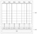
도 2는 도 1의 백라이트 장치(600)를 보여주는 다이어그램이다. 도 2를 참조하면, 본 발명의 실시 예에 따른 백라이트 장치(600)는 백라이트 제어 회로(610) 및 백라이트 유닛(620)을 포함한다. 백라이트 유닛(620)은 열 방향으로 확장되는 복수의 인쇄 회로 기판(PCB1~PCB6)을 포함한다. 예시적으로, 도 2에서 백라이트 유 닛(620)은 6개의 인쇄 회로 기판들(PCB1~PCB6)을 포함하는 것으로 도시되어 있다.2 is a diagram illustrating the
인쇄 회로 기판들(PCB1~PCB6) 각각에 복수의 백라이트 블록이 형성된다. 예시적으로, 도 2에서, 인쇄 회로 기판들(PCB1~PCB6) 각각에 16 개의 백라이트 블록들이 형성되는 것으로 도시되어 있다. 백라이트 블록들은 행 몇 열 방향을 따라 매트릭스 형태로 배열된다. 백라이트 블록은 로컬 디밍 구동의 단위로 이용된다. 예시적으로, 각각의 백라이트 블록은 독립적으로 온 및 오프되고, 각각의 백라이트 블록에 휘도 조절을 위한 펄스 폭 변조 신호가 독립적으로 제공될 것이다. 예시적으로, 본 발명의 실시 예에 따른 백라이트 유닛은 발광 다이오드들(LED, Light Emitting Diode)로 구성될 것이다. 즉, 각각의 백라이트 블록은 하나 또는 그 이상의 발광 다이오드들을 포함할 것이다.A plurality of backlight blocks are formed on each of the printed circuit boards PCB1 to PCB6. For example, in FIG. 2, 16 backlight blocks are formed on each of the printed circuit boards PCB1 to PCB6. The backlight blocks are arranged in a matrix along a few column directions. The backlight block is used as a unit of local dimming driving. In exemplary embodiments, each backlight block may be independently turned on and off, and each backlight block may be independently provided with a pulse width modulated signal for adjusting brightness. For example, the backlight unit according to the embodiment of the present invention may be configured with light emitting diodes (LED). That is, each backlight block will include one or more light emitting diodes.
백라이트 제어 회로(610)는 복수의 제어기 및 저장 회로(612)를 포함한다. 각각의 제어기는 백라이트 유닛(620)의 각각의 인쇄 회로 기판에 대응한다. 즉, 하나의 제어기는 하나의 인쇄 회로 기판의 백라이트 블록들을 제어한다. 각각의 제어기는 대응하는 인쇄 회로 기판의 백라이트 블록들을 독립적으로 제어한다. 예시적으로, 각각의 제어기는 각각 8개의 채널을 갖는 2개의 제어 회로들을 포함할 것이다. 제어기는 백라이트 블록을 온 및 오프할 것이다. 그리고, 제어기는 휘도 정보에 대응하는 펄스 폭 변조 신호를 백라이트 블록에 제공함으로써, 대응하는 백라이트 블록의 휘도를 조절할 것이다. 저장 회로(612)는 백라이트 유닛(620)의 휘도 정보를 저장할 것이다.The
도 3 내지 6은 본 발명의 제 1 실시 예에 따른 로컬 디밍 동작을 설명하기 위한 다이어그램이다. 도 3 내지 6에 백라이트 유닛(620)이 도시되어 있다. 매트릭스 형태로 배열된 백라이트 블록들 중 사선으로 표시된 백라이트 블록은 온 된 백라이트 블록을 나타내고, 사선으로 표시되지 않은 백라이트 블록은 오프 된 백라이트 블록을 나타낸다.3 to 6 are diagrams for describing a local dimming operation according to a first embodiment of the present invention. 3 to 6 illustrate the
액정 패널(500, 도 1 참조)에 화상이 표시될 때, 화상은 행 단위로 그리고 열 방향에 따른 순서로 스캐닝된다. 예시적으로, 액정 패널(500)이 120Hz로 동작하는 경우, 하나의 프레임은 8 번의 스캐닝을 통해 액정 패널(500)에 표시될 것이다.When an image is displayed on the liquid crystal panel 500 (see FIG. 1), the image is scanned in rows and in the order along the column direction. In exemplary embodiments, when the
도 3을 참조하면, 프레임이 전달되기 전에 백라이트 유닛(620)의 모든 백라이트 블록들은 오프 상태일 것이다. 도 4를 참조하면, 액정 패널(500)에 첫 번째 스캐닝이 수행될 때, 즉 액정 패널(500)에 1/8 프레임이 표시될 때, 백라이트 제어 회로(610, 도 2 참조)는 백라이트 유닛(620)의 제 1 및 제 2 행의 백라이트 블록들 중 일부는 온 하고 나머지는 오프 한다. 백라이트 유닛(620)의 제 1 및 제 2 행의 백라이트 블록들은 행 및 열 방향을 따라 교대로 온 및 오프 된다. 이때, 제 1 및 제 2 행에 대응하는 휘도 정보는 저장 회로(612)에 저장되어 있을 것이다. 각각의 백라이트 블록의 휘도 정보에 대응하는 펄스 폭 변조 신호가 제 1 및 제 2 행의 백라이트 블록들에 제공될 것이다.Referring to FIG. 3, all backlight blocks of the
도 5를 참조하면, 액정 패널(500)에 두 번째 스캐닝이 수행될 때, 즉 액정 패널(500)에 2/8 프레임이 표시될 때, 백라이트 제어 회로(610)는 백라이트 유닛(620)의 제 1 및 제 2 행의 백라이트 블록들을 온 한다. 이때, 제 3 및 제 4 행에 대응하는 휘도 정보가 저장 회로(612)에 저장될 것이다.Referring to FIG. 5, when the second scanning is performed on the
도 6을 참조하면, 액정 패널(500)에 세 번째 스캐닝이 수행될 때, 즉 액정 패널(500)에 3/8 프레임이 표시될 때, 백라이트 제어 회로(610)는 백라이트 유닛(620)의 제 3 및 제 4 행의 백라이트 블록들 중 일부를 온 하고 나머지를 오프 한다. 백라이트 제어 회로(610)는 백라이트 유닛(620)의 제 3 및 제 4 행의 백라이트 블록들을 행 및 열 방향을 따라 교대로 온 및 오프 한다. 이때, 제 3 및 제 4 행에 대응하는 휘도 정보는 저장 회로(612)에 저장되어 있을 것이다. 각각의 백라이트 블록들의 휘도 정보에 대응하는 펄스 폭 변조 신호가 제 1 내지 제 4 행의 백라이트 블록들에 제공될 것이다.Referring to FIG. 6, when the third scanning is performed on the
이후의 동작은 도 4 내지 6을 참조하여 설명된 것과 유사하게 수행된다. 액정 패널(500)에 네 번째 스캐닝이 수행될 때, 즉 액정 패널(500)에 4/8 프레임이 표시될 때, 백라이트 유닛(620)의 제 3 및 제 4 행의 백라이트 블록들이 온 될 것이다. 액정 패널(500)에 다섯 번째 스캐닝이 수행될 때, 즉 액정 패널(500)에 5/8 프레임이 표시될 때, 백라이트 유닛(620)의 제 5 및 제 6 행의 백라이트 블록들이 행 및 열 방향을 따라 교대로 온 될 것이다. 액정 패널(500)에 여섯 번째 스캐닝이 수행될 때, 즉 액정 패널(500)에 6/8 프레임이 표시될 때, 백라이트 유닛(620)의 제 5 및 제 6 행의 백라이트 블록들이 온 될 것이다. 액정 패널(500)에 일곱 번째 스캐닝이 수행될 때, 즉 액정 패널(500)에 7/8 프레임이 표시될 때, 백라이트 유닛(620)의 제 7 및 8 행의 백라이트 블록들이 행 및 열 방향을 따라 교대로 온 될 것이다. 액정 패널(500)에 여덟 번째 스캐닝이 수행될 때, 즉 액정 패널(500)에 8/8 프레임이 표시될 때, 백라이트 유닛(620)의 제 7 및 8 행의 백라이트 블록들이 온 될 것이다.Subsequent operations are performed similar to those described with reference to FIGS. 4 to 6. When the fourth scanning is performed on the
상술한 바와 같이, 본 발명의 제 1 실시 예에 따르면, 액정 표시 장치(500)에 화상이 스캐닝될 때, 백라이트 유닛의 온 된 백라이트 블록들과 오프 된 백라이트 블록들의 경계선이 약화된다. 즉, 본 발명의 제 1 실시 예에 따르면 가로줄 얼룩이 감소/방지된다.As described above, according to the first exemplary embodiment of the present invention, when an image is scanned on the
도 7 내지 10은 본 발명의 제 2 실시 예에 따른 로컬 디밍 동작을 설명하기 위한 블록도이다. 도 7 내지 10에 백라이트 유닛(620)이 도시되어 있다. 매트릭스 형태로 배열된 백라이트 블록들 중 사선으로 표시된 백라이트 블록은 온 된 백라이트 블록을 나타내고, 사선으로 표시되지 않은 백라이트 블록은 오프 된 백라이트 블록을 나타낸다.7 to 10 are block diagrams illustrating a local dimming operation according to a second embodiment of the present invention. 7 to 10 illustrate the
액정 패널(500, 도 1 참조)에 화상이 표시될 때, 화상은 행 단위로 그리고 열 방향에 따른 순서로 스캐닝된다. 예시적으로, 액정 패널(500)이 120Hz로 동작하는 경우, 하나의 프레임은 8 번의 스캐닝을 통해 액정 패널(500)에 표시될 것이다.When an image is displayed on the liquid crystal panel 500 (see FIG. 1), the image is scanned in rows and in the order along the column direction. In exemplary embodiments, when the
도 7을 참조하면, 프레임이 전달되기 전에 백라이트 유닛(620)의 모든 백라이트 블록들은 오프 상태일 것이다. 도 8을 참조하면, 액정 패널(500)에 첫 번째 스캐닝이 수행될 때, 즉 액정 패널(500)에 1/8 프레임이 표시될 때, 백라이트 제어 회로(610, 도 2 참조)는 백라이트 유닛(620)의 백라이트 블록들을 행 및 열 방향을 따라 교대로 온 및 오프 한다. 이때, 백라이트 유닛(620)의 휘도 정보는 저장 회로(612)에 저장되어 있을 것이다. 저장되어 있는 휘도 정보에 대응하는 펄스 폭 변조 신호가 백라이트 블록들에 각각 제공될 것이다.Referring to FIG. 7, all backlight blocks of the
도 9를 참조하면, 액정 패널(500)에 두 번째 스캐닝이 수행될 때, 즉 액정 패널(500)에 2/8 프레임이 표시될 때, 백라이트 제어 회로(610)는 백라이트 유닛(620)의 백라이트 블록들을 이전 상태로부터 반전 시킨다. 즉, 액정 패널에 1/8 프레임이 스캐닝될 때 온 되었던 백라이트 블록은 오프 되고, 액정 패널에 1/8 프레임이 스캐닝될 때 오프 되었던 백라이트 블록은 온 될 것이다.Referring to FIG. 9, when the second scanning is performed on the
도 10을 참조하면, 액정 패널(500)에 세 번째 스캐닝이 수행될 때, 즉 액정 패널(500)에 3/8 프레임이 표시될 때, 백라이트 제어 회로(610)는 백라이트 유닛(620)의 백라이트 블록들을 이전 상태로부터 반전 시킨다. 즉, 액정 패널에 2/8 프레임이 스캐닝될 때 온 되었던 백라이트 블록은 오프 되고, 액정 패널에 1/8 프레임이 스캐닝될 때 오프 되었던 백라이트 블록은 온 될 것이다.Referring to FIG. 10, when the third scanning is performed on the
이후의 동작은 도 7 내지 10을 참조하여 설명된 것과 유사하게 수행된다. 액정 패널(500)에 네 번째 스캐닝이 수행될 때, 즉 액정 패널(500)에 4/8 프레임이 표시될 때, 백라이트 유닛(620)의 백라이트 블록들을 이전 상태로부터 반전된다. 액정 패널(500)에 다섯 번째 스캐닝이 수행될 때, 즉 액정 패널(500)에 5/8 프레임이 표시될 때, 백라이트 유닛(620)의 백라이트 블록들을 이전 상태로부터 반전된다. 액정 패널(500)에 여섯 번째 스캐닝이 수행될 때, 즉 액정 패널(500)에 6/8 프레임이 표시될 때, 백라이트 유닛(620)의 백라이트 블록들을 이전 상태로부터 반전된다. 액정 패널(500)에 일곱 번째 스캐닝이 수행될 때, 즉 액정 패널(500)에 7/8 프레임이 표시될 때, 백라이트 유닛(620)의 백라이트 블록들을 이전 상태로부터 반전된다. 액정 패널(500)에 여덟 번째 스캐닝이 수행될 때, 즉 액정 패널(500)에 8/8 프레임이 표시될 때, 백라이트 유닛(620)의 백라이트 블록들을 이전 상태로부터 반전된다.Subsequent operations are performed similar to those described with reference to FIGS. 7 to 10. When the fourth scanning is performed on the
백라이트 제어 회로(610)가 저장 회로(612)에 저장되어 있는 휘도 정보에 응답하여 백라이트 유닛에 펄스 폭 변조 신호를 제공하는 동안, 다음 프레임의 휘도 정보가 저장 회로(612)에 저장될 것이다.While the
상술한 바와 같이, 본 발명의 제 2 실시 예에 따르면, 백라이트 유닛의 온 및 오프된 백라이트 블록들 사이의 경계선이 약화된다. 즉, 본 발명의 제 2 실시 예에 따르면 가로줄 얼룩이 감소/방지된다. 또한, 화상 신호가 액정 패널에 스캐닝될 때마다 백라이트 유닛의 백라이트 블록들이 반전되므로, 본 발명의 제 2 실시 예에 따른 백라이트 블록들은 임펄시브 구동을 수행한다. 따라서, 모션 블러가 감소/방지된다.As described above, according to the second embodiment of the present invention, the boundary between the backlight blocks turned on and off of the backlight unit is weakened. That is, according to the second embodiment of the present invention, the horizontal line stain is reduced / prevented. In addition, since the backlight blocks of the backlight unit are inverted each time an image signal is scanned on the liquid crystal panel, the backlight blocks according to the second embodiment of the present invention perform impulsive driving. Thus, motion blur is reduced / prevented.
상술한 실시 예에서, 본 발명의 실시 예에 따른 백라이트 유닛은 발광 다이오드들로 구성되는 것으로 설명되었다. 그러나, 본 발명의 실시 예에 따른 백라이트 유닛은 발광 다이오드들로 구성되는 것으로 한정되지 않는다. 본 발명의 실시 예에 따른 백라이트 장치 및 그것을 포함하는 액정 표시 장치는 매트릭스 형태로 배열된 백라이트 블록들을 포함한다. 백라이트 블록들은 냉음극 형광 램프(CCFL, Cold Cathode Fluorescent Lamp), 외부 전극 형광 램프(EEFL, External Electrode Fluorescent Lamp), 면광원 램프(FFL, Flat Fluorescent Lamp), 발광 다이오드(LED, Light Emitting Diode) 등을 포함할 수 있다.In the above-described embodiment, the backlight unit according to the embodiment of the present invention has been described as consisting of light emitting diodes. However, the backlight unit according to the embodiment of the present invention is not limited to the light emitting diodes. A backlight device and a liquid crystal display including the same according to an exemplary embodiment of the present invention include backlight blocks arranged in a matrix form. Backlight blocks include Cold Cathode Fluorescent Lamps (CCFLs), External Electrode Fluorescent Lamps (EEFLs), Flat Fluorescent Lamps (FFLs), Light Emitting Diodes (LEDs), etc. It may include.
본 발명의 상세한 설명에서는 구체적인 실시 예에 관하여 설명하였으나, 본 발명의 범위와 기술적 사상에서 벗어나지 않는 한도 내에서 여러 가지 변형이 가능함은 자명하다. 그러므로 본 발명의 범위는 상술한 실시 예에 국한되어 정해져서는 안되며 후술하는 특허청구범위뿐만 아니라 이 발명의 특허청구범위와 균등한 것들에 의해 정해져야 한다.In the detailed description of the present invention, specific embodiments have been described, but it is obvious that various modifications can be made without departing from the scope and spirit of the present invention. Therefore, the scope of the present invention should not be limited to the above-described embodiments, but should be defined by the equivalents of the claims of the present invention as well as the following claims.
도 1은 본 발명의 실시 예에 따른 액정 표시 장치를 보여주는 블록도이다.1 is a block diagram illustrating a liquid crystal display according to an exemplary embodiment of the present invention.
도 2는 도 1의 백라이트 장치를 보여주는 다이어그램이다.FIG. 2 is a diagram illustrating the backlight device of FIG. 1.
도 3 내지 6은 본 발명의 제 1 실시 예에 따른 로컬 디밍 동작을 설명하기 위한 다이어그램이다.3 to 6 are diagrams for describing a local dimming operation according to a first embodiment of the present invention.
도 7 내지 10은 본 발명의 제 2 실시 예에 따른 로컬 디밍 동작을 설명하기 위한 블록도이다.7 to 10 are block diagrams illustrating a local dimming operation according to a second embodiment of the present invention.
Claims (20)
Priority Applications (2)
| Application Number | Priority Date | Filing Date | Title |
|---|---|---|---|
| KR1020080082405A KR20100023563A (en) | 2008-08-22 | 2008-08-22 | Bakclight device and liquid crystal display device including the same |
| US12/545,197 US20100045710A1 (en) | 2008-08-22 | 2009-08-21 | Backlight apparatus and a liquid crystal display including the same |
Applications Claiming Priority (1)
| Application Number | Priority Date | Filing Date | Title |
|---|---|---|---|
| KR1020080082405A KR20100023563A (en) | 2008-08-22 | 2008-08-22 | Bakclight device and liquid crystal display device including the same |
Publications (1)
| Publication Number | Publication Date |
|---|---|
| KR20100023563A true KR20100023563A (en) | 2010-03-04 |
Family
ID=41695950
Family Applications (1)
| Application Number | Title | Priority Date | Filing Date |
|---|---|---|---|
| KR1020080082405A Withdrawn KR20100023563A (en) | 2008-08-22 | 2008-08-22 | Bakclight device and liquid crystal display device including the same |
Country Status (2)
| Country | Link |
|---|---|
| US (1) | US20100045710A1 (en) |
| KR (1) | KR20100023563A (en) |
Families Citing this family (2)
| Publication number | Priority date | Publication date | Assignee | Title |
|---|---|---|---|---|
| KR102663002B1 (en) * | 2019-07-30 | 2024-05-09 | 삼성디스플레이 주식회사 | Display device performing local dimming |
| JP2024009482A (en) * | 2022-07-11 | 2024-01-23 | セイコーエプソン株式会社 | Display systems and circuit devices |
Family Cites Families (6)
| Publication number | Priority date | Publication date | Assignee | Title |
|---|---|---|---|---|
| JP4628770B2 (en) * | 2004-02-09 | 2011-02-09 | 株式会社日立製作所 | Image display device having illumination device and image display method |
| JP2006301053A (en) * | 2005-04-18 | 2006-11-02 | Renesas Technology Corp | Liquid crystal display apparatus |
| US8686937B2 (en) * | 2005-10-29 | 2014-04-01 | Lg Display Co. Ltd. | Backlight unit with feedback circuit and driving method using the same |
| TWI301258B (en) * | 2005-12-12 | 2008-09-21 | Ind Tech Res Inst | Driving system for matrix type backlight module |
| JP4264560B2 (en) * | 2007-01-24 | 2009-05-20 | ソニー株式会社 | Backlight device, backlight control method, and liquid crystal display device |
| JP5117762B2 (en) * | 2007-05-18 | 2013-01-16 | 株式会社半導体エネルギー研究所 | Liquid crystal display |
-
2008
- 2008-08-22 KR KR1020080082405A patent/KR20100023563A/en not_active Withdrawn
-
2009
- 2009-08-21 US US12/545,197 patent/US20100045710A1/en not_active Abandoned
Also Published As
| Publication number | Publication date |
|---|---|
| US20100045710A1 (en) | 2010-02-25 |
Similar Documents
| Publication | Publication Date | Title |
|---|---|---|
| CN101105920B (en) | Liquid crystal display device, driving control circuit and driving method used in same device | |
| US20200051484A1 (en) | Backlight device and display device provided with same | |
| TWI415097B (en) | Liquid crystal display device and driving method thereof | |
| US7612756B2 (en) | Apparatus and method of driving light source for image display device and image display device having the same | |
| KR101158868B1 (en) | Liquid Crystal Display capable of adjusting each brightness level in plural divided areas and method for driving the same | |
| US20140375627A1 (en) | Display device and driving method thereof | |
| US8305332B2 (en) | Backlight unit, liquid crystal display device including the same, and localized dimming method thereof | |
| KR20070003393A (en) | Power control device and method of display module | |
| KR20090053372A (en) | Backlight unit assembly and liquid crystal display including the same | |
| KR100827043B1 (en) | Liquid crystal display device and driving method of the same | |
| KR101227655B1 (en) | Liquid crystal display device and driving method thereof | |
| CN101739982B (en) | Display apparatus | |
| JP4938831B2 (en) | Light emitting device and driving method thereof | |
| US10877315B2 (en) | Backlight and display device provided with same | |
| US8274470B2 (en) | Backlight unit, display apparatus and control method thereof | |
| US9123299B2 (en) | Liquid crystal display device including LED unit using current mirror circuit | |
| JP2011039474A (en) | Light emitting device and method of driving the same | |
| KR20110035836A (en) | LCD Display | |
| JP2011138673A (en) | Backlighting device and image display apparatus | |
| JP2010039136A (en) | Liquid crystal display | |
| KR20100023563A (en) | Bakclight device and liquid crystal display device including the same | |
| KR101126499B1 (en) | Liquid Crystal Display device and method for driving the same | |
| KR20040067290A (en) | driving circuit of liquid crystal display device | |
| JP2007179010A (en) | Liquid crystal display device and driving method of the same | |
| KR20110095710A (en) | LCD and its driving method |
Legal Events
| Date | Code | Title | Description |
|---|---|---|---|
| PA0109 | Patent application |
Patent event code: PA01091R01D Comment text: Patent Application Patent event date: 20080822 |
|
| PG1501 | Laying open of application | ||
| N231 | Notification of change of applicant | ||
| PN2301 | Change of applicant |
Patent event date: 20120912 Comment text: Notification of Change of Applicant Patent event code: PN23011R01D |
|
| PC1203 | Withdrawal of no request for examination | ||
| WITN | Application deemed withdrawn, e.g. because no request for examination was filed or no examination fee was paid |