KR20100006574U - Pressure test device of safety valve - Google Patents
Pressure test device of safety valve Download PDFInfo
- Publication number
- KR20100006574U KR20100006574U KR2020080016854U KR20080016854U KR20100006574U KR 20100006574 U KR20100006574 U KR 20100006574U KR 2020080016854 U KR2020080016854 U KR 2020080016854U KR 20080016854 U KR20080016854 U KR 20080016854U KR 20100006574 U KR20100006574 U KR 20100006574U
- Authority
- KR
- South Korea
- Prior art keywords
- safety valve
- pressure
- plate
- flange
- pressure plate
- Prior art date
- Legal status (The legal status is an assumption and is not a legal conclusion. Google has not performed a legal analysis and makes no representation as to the accuracy of the status listed.)
- Ceased
Links
Images




Classifications
-
- G—PHYSICS
- G01—MEASURING; TESTING
- G01M—TESTING STATIC OR DYNAMIC BALANCE OF MACHINES OR STRUCTURES; TESTING OF STRUCTURES OR APPARATUS, NOT OTHERWISE PROVIDED FOR
- G01M13/00—Testing of machine parts
- G01M13/003—Machine valves
-
- F—MECHANICAL ENGINEERING; LIGHTING; HEATING; WEAPONS; BLASTING
- F15—FLUID-PRESSURE ACTUATORS; HYDRAULICS OR PNEUMATICS IN GENERAL
- F15B—SYSTEMS ACTING BY MEANS OF FLUIDS IN GENERAL; FLUID-PRESSURE ACTUATORS, e.g. SERVOMOTORS; DETAILS OF FLUID-PRESSURE SYSTEMS, NOT OTHERWISE PROVIDED FOR
- F15B19/00—Testing; Calibrating; Fault detection or monitoring; Simulation or modelling of fluid-pressure systems or apparatus not otherwise provided for
- F15B19/005—Fault detection or monitoring
-
- F—MECHANICAL ENGINEERING; LIGHTING; HEATING; WEAPONS; BLASTING
- F16—ENGINEERING ELEMENTS AND UNITS; GENERAL MEASURES FOR PRODUCING AND MAINTAINING EFFECTIVE FUNCTIONING OF MACHINES OR INSTALLATIONS; THERMAL INSULATION IN GENERAL
- F16K—VALVES; TAPS; COCKS; ACTUATING-FLOATS; DEVICES FOR VENTING OR AERATING
- F16K17/00—Safety valves; Equalising valves, e.g. pressure relief valves
- F16K17/02—Safety valves; Equalising valves, e.g. pressure relief valves opening on surplus pressure on one side; closing on insufficient pressure on one side
-
- F—MECHANICAL ENGINEERING; LIGHTING; HEATING; WEAPONS; BLASTING
- F16—ENGINEERING ELEMENTS AND UNITS; GENERAL MEASURES FOR PRODUCING AND MAINTAINING EFFECTIVE FUNCTIONING OF MACHINES OR INSTALLATIONS; THERMAL INSULATION IN GENERAL
- F16K—VALVES; TAPS; COCKS; ACTUATING-FLOATS; DEVICES FOR VENTING OR AERATING
- F16K37/00—Special means in or on valves or other cut-off apparatus for indicating or recording operation thereof, or for enabling an alarm to be given
- F16K37/0075—For recording or indicating the functioning of a valve in combination with test equipment
-
- Y—GENERAL TAGGING OF NEW TECHNOLOGICAL DEVELOPMENTS; GENERAL TAGGING OF CROSS-SECTIONAL TECHNOLOGIES SPANNING OVER SEVERAL SECTIONS OF THE IPC; TECHNICAL SUBJECTS COVERED BY FORMER USPC CROSS-REFERENCE ART COLLECTIONS [XRACs] AND DIGESTS
- Y10—TECHNICAL SUBJECTS COVERED BY FORMER USPC
- Y10S—TECHNICAL SUBJECTS COVERED BY FORMER USPC CROSS-REFERENCE ART COLLECTIONS [XRACs] AND DIGESTS
- Y10S251/00—Valves and valve actuation
Landscapes
- Engineering & Computer Science (AREA)
- General Engineering & Computer Science (AREA)
- Mechanical Engineering (AREA)
- Physics & Mathematics (AREA)
- Fluid Mechanics (AREA)
- General Physics & Mathematics (AREA)
- Testing Of Devices, Machine Parts, Or Other Structures Thereof (AREA)
Abstract
정확하고 신속하게 밸브의 결함상태를 테스트할 수 있으며 다양한 크기의 안전밸브를 장착할 수 있도록 한 안전밸브의 압력시험장치에 관한 것이다.The present invention relates to a pressure testing device for a safety valve that can accurately and quickly test a valve defect condition and to be able to install safety valves of various sizes.
이는 베이스판(3)과, 베이스판(3)의 상부에 지지대(6)에 의해서 일정간격 유지되고 관통공이 형성된 상판(2)과, 상판(2)의 관통공 가장자리 상면에 지지되고 상기 안전밸브(9)의 플랜지(9a)가 안착되며 가스주입공(1a)이 형성된 압력판(1)과, 각각 상판(2)에 가장자리로부터 압력판(1)을 향하여 왕복이동가능하게 결합되며 그 선단에 상기 플랜지(9a)의 상면을 클램프시키는 클램프(21)가 결합된 복수의 이동블럭(20)과, 상기 상판(2)의 하부에서 상기 압력판(1)을 지지시키며 상기 가스주입공(1a)을 통하여 시험가스를 주입시키는 가스공급실린더(30)와, 상기 압력판(1)과 가스공급실린더(30)를 승강시키는 유압잭(40)을 구비한다.It is supported by the base plate 3, the upper plate 2 is maintained at a constant interval by the support 6 on the base plate 3, the through hole is formed, and the upper surface of the edge of the through hole of the upper plate 2 and the safety valve The flange 9a of 9 is seated and the pressure plate 1 having the gas injection hole 1a formed therein is coupled to the upper plate 2 so as to be reciprocally moved from the edge toward the pressure plate 1, and the flange at its tip. A plurality of moving blocks 20 coupled with a clamp 21 for clamping the upper surface of 9a and the pressure plate 1 are supported by the lower part of the upper plate 2 and tested through the gas injection hole 1a. The gas supply cylinder 30 which injects gas, and the hydraulic jack 40 which raises and lowers the said pressure plate 1 and the gas supply cylinder 30 are provided.
상기와 같은 본 고안 장치는 이동블럭(20), 클램프(21), 가스공급실린더(30) 및 유압잭(40)을 구비함으로써 안전밸브의 플랜지(9a) 직경이 다른 다양한 크기의 안전밸브를 장착할 수 있게 하여 범용적으로 사용이 가능하며, 유압잭의 작동으로 안전밸브의 클램프를 가능하게 하므로 가스 압력시험을 간편하게 할 수 있게 한다. The present invention as described above is equipped with a movable block 20, a clamp 21, a gas supply cylinder 30 and the hydraulic jack 40 to install a safety valve of various sizes different in the flange (9a) diameter of the safety valve. It can be used universally, and the operation of the hydraulic jack enables the clamping of the safety valve, thus simplifying the gas pressure test.
안전밸브, 플랜지, 압력판, 유압잭, 이동블럭, 클램프 Safety valve, flange, pressure plate, hydraulic jack, movable block, clamp
Description
본 고안은 압력밸브의 안전시험 장치에 관한 것으로서, 특히 정확하고 신속하게 밸브의 결함상태를 테스트할 수 있으며 다양한 크기의 안전밸브를 장착할 수 있도록 한 안전밸브의 압력시험장치에 관한 것이다.The present invention relates to a safety test apparatus for a pressure valve, and more particularly, to a pressure test apparatus for a safety valve that can accurately and quickly test a defect state of a valve and to mount safety valves of various sizes.
일반적으로 안전밸브는 사용하는 기기류에 따라 허용되는 최대압력을 한정하며, 최대압력이 되면 자동적으로 밸브가 열리면서 가스를 방출하여 압력을 감소시킴으로써 설정압력으로 유지될 수 있도록 한다.In general, the safety valve limits the maximum pressure allowed according to the equipment used, and when the maximum pressure is reached, the valve opens automatically, releasing gas to reduce the pressure so that the pressure can be maintained at the set pressure.
이러한 안전밸브들은 신규장착이나 보수 후 조립전에 설정압에서 작동이 되는지 여부를 시험하게 된다.These safety valves are tested for their ability to operate at the set pressure before assembly after retrofitting or maintenance.
통상의 안전밸브 압력시험 장치는 안전밸브 전단의 플랜지에 맞추어 각각의 사이즈별로 단관플랜지를 볼트 및 너트로 체결하여서 질소가스를 주입시킴으로써 압력 시험을 하는 방식이다.Conventional safety valve pressure test apparatus is a pressure test by injecting nitrogen gas by fastening the single pipe flange with bolts and nuts according to the flange of the front end of the safety valve.
그러나 이와 같은 시험장치는 안전밸브의 크기에 따라 다수의 단관플랜지를 준비해야 할 뿐만 아니라 볼트, 너트의 체결 방식에 따른 많은 시간과 노동력이 소요되며, 밸브의 기밀을 유지하기가 어렵다.However, such a test apparatus requires not only a large number of single pipe flanges to be prepared depending on the size of the safety valve, but also requires a lot of time and labor according to the bolt and nut fastening method, and it is difficult to maintain the confidentiality of the valve.
또한, 안전밸브는 대부분 중량물로써 압력시험 장치에 탈, 부착시 어려움이 있으며 설정압력 시험시 질소 가스의 사용량이 많다는 문제점이 있었다.In addition, the safety valve has a problem in that it is difficult to remove and attach to the pressure test apparatus as a heavy material, and the amount of nitrogen gas used during the set pressure test is large.
본 고안은 상기와 같은 문제점을 해결하기 위한 것으로서, 크기가 다른 안전밸브들은 장착시킬 수 있으며 간편하게 압력시험을 할 수 있도록 한 안전밸브의 압력시험 장치를 제공하는 데 그 목적이 있다.The present invention is to solve the above problems, the purpose of the present invention is to provide a pressure testing device for a safety valve that can be equipped with safety valves of different sizes and can be easily pressure test.
상기 목적을 달성하는 본 고안은 배관 연결용 플랜지를 가지는 안전밸브의 압력시험 장치에 있어서,The present invention to achieve the above object in the pressure test device of the safety valve having a flange for pipe connection,
베이스판과, 상기 베이스판의 상부에 지지대에 의해서 일정간격 유지되고 관통공이 형성된 상판과, 상기 상판의 관통공 가장자리 상면에 지지되고 상기 안전밸브의 플랜지가 안착되며 가스주입공이 형성된 압력판과, 각각 상기 상판에 가장자리로부터 상기 압력판을 향하여 왕복이동가능하게 결합되며 그 선단에 상기 플랜지의 상면을 클램프시키는 클램프가 결합된 복수의 이동블럭과, 상기 상판의 하부에서 상기 압력판을 지지시키며 상기 가스주입공을 통하여 시험가스를 주입시키는 가스공급실린더와, 상기 압력판과 가스공급실린더를 승강시키는 유압잭을 구비하여서,A base plate, an upper plate maintained at a predetermined interval by a support on the base plate, and having a through hole formed therein; A plurality of movable blocks coupled to the upper plate reciprocally from the edge toward the pressure plate and having a clamp coupled to the top thereof to clamp the upper surface of the flange; A gas supply cylinder for injecting a test gas, and a hydraulic jack for elevating the pressure plate and the gas supply cylinder,
상기 유압잭의 작동에 따라 상기 플랜지가 상기 클램프와 압력판 사이에 고정되도록 된 것을 특징으로 한다.According to the operation of the hydraulic jack is characterized in that the flange is fixed between the clamp and the pressure plate.
또한, 상기 각 이동블럭에 안내홈이 형성되고, 상기 안내홈에 상기 각 클램프가 이동가능하게 결합된 것을 특징으로 한다.In addition, a guide groove is formed in each of the movable blocks, and each of the clamps is movably coupled to the guide groove.
또한, 보조오링의 직경이 다른 복수의 보조압력판을 더 구비하여서,In addition, further comprising a plurality of auxiliary pressure plates of different diameter of the auxiliary O-ring,
상기 플랜지의 직경에 대응되는 크기의 보조오링을 가지는 상기 보조압력판을 선택하여 상기 압력판에 탑재할 수 있도록 한 것을 특징으로 한다.The auxiliary pressure plate having an auxiliary O-ring having a size corresponding to the diameter of the flange is selected to be mounted on the pressure plate.
본 고안 장치는 이동블럭, 클램프, 가스공급실린더 및 유압잭을 구비함으로써 안전밸브의 플랜지 직경이 다른 다양한 크기의 안전밸브를 장착할 수 있게 하여 범용적으로 사용이 가능하며, 유압잭의 작동으로 안전밸브의 클램프를 가능하게 하므로 가스 압력시험을 간편하게 할 수 있게 한다. The device has a movable block, a clamp, a gas supply cylinder, and a hydraulic jack, so that safety valves of various sizes with different flange diameters of safety valves can be installed and can be used universally. This enables clamping to simplify gas pressure testing.
본 고안은 안전밸브의 점검시 정확하고, 신속하게 설정압력 및 결함상태를The present invention accurately and quickly checks the set pressure and fault condition when checking the safety valve.
시험할 수 있는 장치를 제공한다.Provide a device for testing.
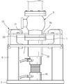
본 고안 실시예의 장치를 나타낸 도 1 및 도 2를 참조하면, 이는 베이스판(3)과, 상기 베이스판(3)의 상부에 지지대(6)에 의해서 일정간격 유지되고 관통공이 형성된 상판(2)과, 상기 상판(2)의 관통공 가장자리 상면에 지지되고 상기 안전밸브(9)의 플랜지(9a)가 안착되며 가스주입공(1a)이 형성된 압력판(1)과, 각각 상기 상판(2)에 가장자리로부터 상기 압력판(1)을 향하여 왕복이동가능하게 결합되며 그 선단에 상기 플랜지(9a)의 상면을 클램프시키는 클램프(21)가 결합된 복수의 이동블럭(20)과, 상기 상판(2)의 하부에서 상기 압력판(1)을 지지시키며 상기 가스 주입공(1a)을 통하여 시험가스를 주입시키는 가스공급실린더(30)와, 상기 압력판(1)과 가스공급실린더(30)를 승강시키는 유압잭(40)을 구비한다.1 and 2 showing the device of the present invention, it is a
상기 상판(2)에는 상기 각 이동블럭(20)들이 이동가능하게 결합되는 가이드홈(2a)이 형성되어 있으며, 상기 압력판(1)에는 플랜지(9a)와의 사이에서 가스누설을 방지시키는 오링(10)이 결합되어 있다.The
또한, 상기 각 이동블럭(20)에는 안내홈(22)이 형성되고, 상기 안내홈(22)에 상기 각 클램프(21)가 이동가능하게 결합되어 있다.In addition, a
한편, 도 3 및 도 4에 도시된 바와 같이, 보조오링(11)의 직경이 다른 복수의 보조압력판(50)을 더 구비하여서, 상기 플랜지(9a)의 직경에 대응되는 크기의 보조오링(11)을 가지는 상기 보조압력판(50)을 선택하여 상기 압력판(1)에 탑재할 수 있도록 하였다.Meanwhile, as shown in FIGS. 3 and 4, the auxiliary o-
이 경우 압력시험을 하고자 하는 안전밸브(9)의 플랜지(9a) 크기에 대응되는 크기의 보조압력판(50)으로 인하여 다양한 크기의 안전밸브(9)를 시험할 수 있도록 한다.In this case, it is possible to test the safety valve (9) of various sizes due to the
상기와 같은 구성의 장치를 사용하는 방법은 다음과 같다.The method of using the apparatus of the above structure is as follows.
먼저, 시험하고자 하는 안전밸브(9)의 플랜지(9a)를 압력판(1)에 안착시키고, 각 이동블럭(20)을 플랜지(9a)를 향하여 이동시켜서 각 클램프(21)를 플랜지(9a)의 직상부에 위치시킨다.First, the
이때 압력판(1)에는 도 3, 도 4a 및 도 4b에서와 같이, 시험하고자 하는 안전밸브(9)의 플랜지(9a)크기에 대응되는 직경의 보조오링(11)을 가지는 보조압력 판(50)을 장착한다.At this time, the
이어서 도 1 또는 도 3에 도시된 바와 같이, 상기 유압잭(40)을 작동시키게 되면, 상기 가스공급실린더(30), 압력판(1) 및 안전밸브(9)가 상승하게 되고, 플랜지(9a)가 클램프(21)와 압력판(1) 사이에 클램프되게 된다.Subsequently, as shown in FIG. 1 or 3, when the
이와 같은 상태에서 압력충진구(7)를 통하여 질소가스를 주입시켜서 안전밸브(9)가 설정압력에서 작동되는지 여부를 시험한다.In this state, nitrogen gas is injected through the pressure filling port (7) to test whether the safety valve (9) is operated at the set pressure.
상기와 같은 본 고안 장치는 이동블럭(20), 클램프(21), 가스공급실린더(30) 및 유압잭(40)을 구비함으로써 안전밸브의 플랜지(9a) 직경이 다른 다양한 크기의 안전밸브를 장착할 수 있게 하여 범용적으로 사용이 가능하며, 유압잭의 작동으로 안전밸브의 클램프를 가능하게 하므로 가스 압력시험을 간편하게 할 수 있게 한다. The present invention as described above is equipped with a
도 1은 본 고안 장치에 안전밸브가 클램핑된 상태를 나타낸 사시도,1 is a perspective view showing a state in which the safety valve is clamped to the device,
도 2는 본 고안 장치의 측면도,2 is a side view of the device of the present invention,
도 3은 본 고안 장치의 다른 실시예를 나타낸 측면도,Figure 3 is a side view showing another embodiment of the present invention device,
도 4a 및 도 4b는 보조압력판을 나타낸 평면도이다.4A and 4B are plan views illustrating the auxiliary pressure plate.
Claims (3)
Priority Applications (1)
| Application Number | Priority Date | Filing Date | Title |
|---|---|---|---|
| KR2020080016854U KR20100006574U (en) | 2008-12-19 | 2008-12-19 | Pressure test device of safety valve |
Applications Claiming Priority (1)
| Application Number | Priority Date | Filing Date | Title |
|---|---|---|---|
| KR2020080016854U KR20100006574U (en) | 2008-12-19 | 2008-12-19 | Pressure test device of safety valve |
Publications (1)
| Publication Number | Publication Date |
|---|---|
| KR20100006574U true KR20100006574U (en) | 2010-06-29 |
Family
ID=44452014
Family Applications (1)
| Application Number | Title | Priority Date | Filing Date |
|---|---|---|---|
| KR2020080016854U Ceased KR20100006574U (en) | 2008-12-19 | 2008-12-19 | Pressure test device of safety valve |
Country Status (1)
| Country | Link |
|---|---|
| KR (1) | KR20100006574U (en) |
Cited By (15)
| Publication number | Priority date | Publication date | Assignee | Title |
|---|---|---|---|---|
| CN103104795A (en) * | 2013-01-06 | 2013-05-15 | 合肥通用机械研究院 | Torque balance lifting and clamping device for valve low-temperature test |
| KR101370591B1 (en) * | 2012-05-15 | 2014-03-06 | 대진대학교 산학협력단 | Apparatus for testing valve |
| CN104634596A (en) * | 2014-12-22 | 2015-05-20 | 朗安(天津)科技发展有限公司 | Tool for detecting fuel gas pressure regulator |
| CN104729841A (en) * | 2013-12-24 | 2015-06-24 | 珠海格力电器股份有限公司 | Safety valve testing device |
| CN105606354A (en) * | 2016-02-03 | 2016-05-25 | 中国人民解放军装甲兵工程学院 | Armored vehicle integrated transmission apparatus supporting seat vertical direction stress calibration testing table |
| CN105738091A (en) * | 2016-02-03 | 2016-07-06 | 中国人民解放军装甲兵工程学院 | Armored vehicle integrated transmission device supporting base horizontal radial stress calibration test stand |
| CN109163901A (en) * | 2018-08-25 | 2019-01-08 | 西安特种设备检验检测院 | Safety valve intelligent checking detection device and method based on big data |
| KR20190000362U (en) * | 2017-07-31 | 2019-02-11 | 주식회사 한국가스기술공사 | Test apparatus for natural gas facility |
| KR102015627B1 (en) | 2018-06-28 | 2019-08-28 | (주)보성 | Device for testing valve |
| CN110823558A (en) * | 2019-11-29 | 2020-02-21 | 长庆石油勘探局有限公司技术监测中心 | Pressure testing device and method for compatible safety valve |
| CN111746742A (en) * | 2020-06-22 | 2020-10-09 | 沪东中华造船(集团)有限公司 | Pressure test method for chemical ship cargo hold PV valve |
| CN112483512A (en) * | 2021-01-06 | 2021-03-12 | 南京芬曼诗贸易有限公司 | On-line pressure detection terminal for hydraulic cylinder of automobile gearbox |
| KR20210033089A (en) | 2019-09-17 | 2021-03-26 | (주)보성 | Testing Apparatus For Safety Valve |
| KR20210033561A (en) | 2019-09-18 | 2021-03-29 | (주)보성 | Testing Apparatus For Safety Valve |
| CN119042398A (en) * | 2024-08-26 | 2024-11-29 | 山东中科计量有限公司 | Safety valve on-line measuring device |
-
2008
- 2008-12-19 KR KR2020080016854U patent/KR20100006574U/en not_active Ceased
Cited By (19)
| Publication number | Priority date | Publication date | Assignee | Title |
|---|---|---|---|---|
| KR101370591B1 (en) * | 2012-05-15 | 2014-03-06 | 대진대학교 산학협력단 | Apparatus for testing valve |
| CN103104795A (en) * | 2013-01-06 | 2013-05-15 | 合肥通用机械研究院 | Torque balance lifting and clamping device for valve low-temperature test |
| CN104729841A (en) * | 2013-12-24 | 2015-06-24 | 珠海格力电器股份有限公司 | Safety valve testing device |
| CN104634596A (en) * | 2014-12-22 | 2015-05-20 | 朗安(天津)科技发展有限公司 | Tool for detecting fuel gas pressure regulator |
| CN105606354A (en) * | 2016-02-03 | 2016-05-25 | 中国人民解放军装甲兵工程学院 | Armored vehicle integrated transmission apparatus supporting seat vertical direction stress calibration testing table |
| CN105738091A (en) * | 2016-02-03 | 2016-07-06 | 中国人民解放军装甲兵工程学院 | Armored vehicle integrated transmission device supporting base horizontal radial stress calibration test stand |
| CN105738091B (en) * | 2016-02-03 | 2018-12-11 | 中国人民解放军装甲兵工程学院 | Armored vehicle comprehensive actuator support base horizontal radial stress Calibrating experimental bench |
| CN105606354B (en) * | 2016-02-03 | 2018-12-11 | 中国人民解放军装甲兵工程学院 | Armored vehicle comprehensive actuator support base vertical direction stress Calibrating experimental bench |
| KR20190000362U (en) * | 2017-07-31 | 2019-02-11 | 주식회사 한국가스기술공사 | Test apparatus for natural gas facility |
| KR102015627B1 (en) | 2018-06-28 | 2019-08-28 | (주)보성 | Device for testing valve |
| CN109163901A (en) * | 2018-08-25 | 2019-01-08 | 西安特种设备检验检测院 | Safety valve intelligent checking detection device and method based on big data |
| CN109163901B (en) * | 2018-08-25 | 2019-07-16 | 西安特种设备检验检测院 | Safety valve intelligent checking detection device and method based on big data |
| KR20210033089A (en) | 2019-09-17 | 2021-03-26 | (주)보성 | Testing Apparatus For Safety Valve |
| KR20210033561A (en) | 2019-09-18 | 2021-03-29 | (주)보성 | Testing Apparatus For Safety Valve |
| CN110823558A (en) * | 2019-11-29 | 2020-02-21 | 长庆石油勘探局有限公司技术监测中心 | Pressure testing device and method for compatible safety valve |
| CN111746742A (en) * | 2020-06-22 | 2020-10-09 | 沪东中华造船(集团)有限公司 | Pressure test method for chemical ship cargo hold PV valve |
| CN112483512A (en) * | 2021-01-06 | 2021-03-12 | 南京芬曼诗贸易有限公司 | On-line pressure detection terminal for hydraulic cylinder of automobile gearbox |
| CN119042398A (en) * | 2024-08-26 | 2024-11-29 | 山东中科计量有限公司 | Safety valve on-line measuring device |
| CN119042398B (en) * | 2024-08-26 | 2025-03-11 | 山东中科计量有限公司 | Safety valve on-line measuring device |
Similar Documents
| Publication | Publication Date | Title |
|---|---|---|
| KR20100006574U (en) | Pressure test device of safety valve | |
| CN201795902U (en) | Tightness tester for water pump casing of automobile | |
| US4520655A (en) | Valve testing apparatus | |
| KR101479308B1 (en) | Testing devices for both hydraulic and pneumatic of welded tubes | |
| CN103062586B (en) | Vibrator support device and its hydraulic system, and vibrator system | |
| KR20100007130U (en) | The fluid valve test equipment | |
| KR200401828Y1 (en) | Device testing air leak | |
| CN106935296A (en) | A kind of PWR nuclear power plant fuel assembly crawl test instrument being horizontally mounted | |
| CN104390743A (en) | Engine cylinder block leakage check device | |
| CN102353501A (en) | Tool for testing air tightness of cylinder head cover | |
| CN108195515A (en) | A kind of valve-testing machine | |
| KR20160147318A (en) | Support for marine cooling jacket hydrostatic test | |
| CN215952896U (en) | Air tightness testing machine | |
| JP2774450B2 (en) | Safety valve testing equipment | |
| CN102611263A (en) | Pressure test device for base of explosion-proof electric machine | |
| CN215967627U (en) | Air detection type machine tool positioning fixture | |
| US8704543B2 (en) | Test head moving apparatus and electronic component testing apparatus | |
| CN104729866B (en) | Test tool of marine hydraulic capstan | |
| KR200225812Y1 (en) | Tester of leakage | |
| CN210397063U (en) | Automatic pressure tester for vertical pipeline pump series | |
| CN211263115U (en) | Test piece assembling and demolding integrated equipment for concrete impermeability instrument | |
| CN209043539U (en) | A kind of pressure testing device of small dimension y-type filter body | |
| CN211602304U (en) | Low-pressure sealing test device of multistage hydraulic oil cylinder | |
| CN210005178U (en) | aluminum wheel gas pressurizing leakage detecting device | |
| CN111157189B (en) | Multifunctional test bench |
Legal Events
| Date | Code | Title | Description |
|---|---|---|---|
| A201 | Request for examination | ||
| UA0108 | Application for utility model registration |
St.27 status event code: A-0-1-A10-A12-nap-UA0108 |
|
| UA0201 | Request for examination |
St.27 status event code: A-1-2-D10-D11-exm-UA0201 |
|
| D13-X000 | Search requested |
St.27 status event code: A-1-2-D10-D13-srh-X000 |
|
| D14-X000 | Search report completed |
St.27 status event code: A-1-2-D10-D14-srh-X000 |
|
| UG1501 | Laying open of application |
St.27 status event code: A-1-1-Q10-Q12-nap-UG1501 |
|
| E902 | Notification of reason for refusal | ||
| UE0902 | Notice of grounds for rejection |
St.27 status event code: A-1-2-D10-D21-exm-UE0902 |
|
| R18-X000 | Changes to party contact information recorded |
St.27 status event code: A-3-3-R10-R18-oth-X000 |
|
| E13-X000 | Pre-grant limitation requested |
St.27 status event code: A-2-3-E10-E13-lim-X000 |
|
| P11-X000 | Amendment of application requested |
St.27 status event code: A-2-2-P10-P11-nap-X000 |
|
| P13-X000 | Application amended |
St.27 status event code: A-2-2-P10-P13-nap-X000 |
|
| E601 | Decision to refuse application | ||
| UE0601 | Decision on rejection of utility model registration |
St.27 status event code: N-2-6-B10-B15-exm-UE0601 |
|
| P22-X000 | Classification modified |
St.27 status event code: A-2-2-P10-P22-nap-X000 |
|
| P22-X000 | Classification modified |
St.27 status event code: A-2-2-P10-P22-nap-X000 |
|
| R18-X000 | Changes to party contact information recorded |
St.27 status event code: A-3-3-R10-R18-oth-X000 |
|
| R18 | Changes to party contact information recorded |
Free format text: ST27 STATUS EVENT CODE: A-3-3-R10-R18-OTH-X000 (AS PROVIDED BY THE NATIONAL OFFICE) |
|
| R18-X000 | Changes to party contact information recorded |
St.27 status event code: A-3-3-R10-R18-oth-X000 |