KR20090086768A - scanner - Google Patents
scanner Download PDFInfo
- Publication number
- KR20090086768A KR20090086768A KR1020080012223A KR20080012223A KR20090086768A KR 20090086768 A KR20090086768 A KR 20090086768A KR 1020080012223 A KR1020080012223 A KR 1020080012223A KR 20080012223 A KR20080012223 A KR 20080012223A KR 20090086768 A KR20090086768 A KR 20090086768A
- Authority
- KR
- South Korea
- Prior art keywords
- transparent body
- light
- light source
- scanner
- glass plate
- Prior art date
- Legal status (The legal status is an assumption and is not a legal conclusion. Google has not performed a legal analysis and makes no representation as to the accuracy of the status listed.)
- Ceased
Links
Images


Classifications
-
- H—ELECTRICITY
- H04—ELECTRIC COMMUNICATION TECHNIQUE
- H04N—PICTORIAL COMMUNICATION, e.g. TELEVISION
- H04N1/00—Scanning, transmission or reproduction of documents or the like, e.g. facsimile transmission; Details thereof
- H04N1/024—Details of scanning heads ; Means for illuminating the original
- H04N1/028—Details of scanning heads ; Means for illuminating the original for picture information pick-up
- H04N1/02815—Means for illuminating the original, not specific to a particular type of pick-up head
- H04N1/02845—Means for illuminating the original, not specific to a particular type of pick-up head using an elongated light source, e.g. tubular lamp, LED array
- H04N1/02855—Means for illuminating the original, not specific to a particular type of pick-up head using an elongated light source, e.g. tubular lamp, LED array in combination with a light guide, e.g. optical fibre, glass plate
-
- H—ELECTRICITY
- H04—ELECTRIC COMMUNICATION TECHNIQUE
- H04N—PICTORIAL COMMUNICATION, e.g. TELEVISION
- H04N1/00—Scanning, transmission or reproduction of documents or the like, e.g. facsimile transmission; Details thereof
- H04N1/04—Scanning arrangements, i.e. arrangements for the displacement of active reading or reproducing elements relative to the original or reproducing medium, or vice versa
- H04N1/19—Scanning arrangements, i.e. arrangements for the displacement of active reading or reproducing elements relative to the original or reproducing medium, or vice versa using multi-element arrays
- H04N1/191—Scanning arrangements, i.e. arrangements for the displacement of active reading or reproducing elements relative to the original or reproducing medium, or vice versa using multi-element arrays the array comprising a one-dimensional [1D] array
- H04N1/192—Simultaneously or substantially simultaneously scanning picture elements on one main scanning line
- H04N1/193—Simultaneously or substantially simultaneously scanning picture elements on one main scanning line using electrically scanned linear arrays, e.g. linear CCD arrays
- H04N1/1935—Optical means for mapping the whole or part of a scanned line onto the array
- H04N1/1937—Optical means for mapping the whole or part of a scanned line onto the array using a reflecting element, e.g. a mirror or a prism
Landscapes
- Engineering & Computer Science (AREA)
- Multimedia (AREA)
- Signal Processing (AREA)
- Image Input (AREA)
Abstract
본 발명은 표면의 반사 특성이 서로 다른 두 종류의 스캔 대상물을 각각 스캔할 수 있도록 구성된 스캐너에 관한 것이다. 본 발명에 따른 스캐너는, 스캔 대상물과 접촉하는 각 면이 서로 다른 반사 특성을 가지도록 배치된 제1 및 제2 투명체, 상기 제1 및 제2 투명체를 향해 빛을 발하는 광원, 상기 제1 투명체나 상기 제2 투명체 인근을 선택적으로 지나게 배치된 캐리어 및 상기 캐리어에 장착되며, 상기 제1 또는 제2 투명체를 통과한 빛을 받아 전기적 신호로 변환하는 이미지 센서를 포함하여 이루어진다.The present invention relates to a scanner configured to scan each of two types of scan objects having different reflective properties of the surface. The scanner according to the present invention includes a first and a second transparent body arranged so that each surface in contact with the scan object has different reflection characteristics, a light source emitting light toward the first and second transparent body, the first transparent body or And an image sensor mounted to the carrier selectively passing through the vicinity of the second transparent body and receiving an image of the light passing through the first or second transparent body and converting the light into an electrical signal.
Description
본 발명은 스캐너에 관한 것으로, 좀더 상세하게는 표면의 반사 특성이 서로 다른 두 종류의 스캔 대상물을 각각 스캔할 수 있도록 구성된 스캐너에 관한 것이다.The present invention relates to a scanner, and more particularly, to a scanner configured to scan two kinds of scanning objects having different surface reflection characteristics.
서류나 사진 등 아날로그 형태로 존재하는 정보를 복제하거나 디지털 정보로 전환하여 활용하기 위해 스캐너가 사용된다.Scanners are used to copy or convert information that exists in analog form, such as documents or photographs, into digital information.
일반적인 스캐너는, 스캔 대상물이 올려지는 유리판, 상기 유리판의 아래에 배치되어 유리판을 향해 빛을 조사하는 광원, 상기 광원에서 발산된 후 상기 스캔 대상물의 표면에서 반사된 빛을 받아 전기 신호를 출력하는 이미지 센서 및 상기 이미지 센서에서 출력된 아날로그 신호를 디지털 신호로 전환하는 디지털 신호 처리 프로세서를 포함하여 이루어진다.A typical scanner includes a glass plate on which a scan object is placed, a light source disposed under the glass plate to irradiate light toward the glass plate, and an image outputting an electric signal by receiving light reflected from the surface of the scan object after being emitted from the light source. And a digital signal processing processor for converting an analog signal output from the image sensor into a digital signal.
상기 스캐너가 작동하면 상기 광원이 상기 유리판을 향해 빛을 발산한다. 상기 빛은 상기 유리판을 투과한 후 상기 유리판 위에 올려진 스캔 대상물의 표면에서 반사된 후 상기 이미지 센서로 전달된다.When the scanner is activated, the light source emits light toward the glass plate. The light is transmitted through the glass plate, reflected from the surface of the scan object placed on the glass plate, and then transmitted to the image sensor.
상기 스캔 대상물의 표면의 명암에 따라 빛의 반사량이 달라지므로, 상기 이 미지 센서는 반사된 빛의 양에 상응하는 전기 신호를 출력하게 된다. 좀더 상세히 설명하면, 서류에 인쇄된 글자 부분은 반사율이 적고 글자가 없는 여백은 반사율이 높으므로, 상기 이미지 센서에 입사되는 빛 중 글자 부분에 해당하는 영역은 어둡고 여백 부분에 해당하는 영역은 밝다. 이와 같은 원리로 이미지 센서에 상기 스캔 대상물의 상이 맺히고 상기 이미지 센서는 스캔 대상물의 상에 상응하는 전기 신호를 출력하게 된다. 상기 이미지 센서에서 출력된 아날로그 전기 신호는 상기 디지털 신호 처리 프로세서에 의해 디지털 신호로 전환된다.Since the amount of reflection of light varies according to the contrast of the surface of the scan object, the image sensor outputs an electrical signal corresponding to the amount of reflected light. In more detail, since the letter portion printed on the document has a low reflectance and the margin without letters has a high reflectance, the area corresponding to the letter portion of the light incident on the image sensor is dark and the area corresponding to the margin portion is bright. In this manner, the image of the scan object is formed on the image sensor, and the image sensor outputs an electrical signal corresponding to the image of the scan object. The analog electrical signal output from the image sensor is converted into a digital signal by the digital signal processing processor.
위와 같이 스캐너를 통해 얻어진 스캔 정보는 스캔 대상물을 복사하거나, 스캔 대상물의 표면에 있는 정보를 디지털화하여 저장하는데 유용하게 사용된다.As described above, the scan information obtained through the scanner is useful for copying a scan object or digitizing and storing information on the surface of the scan object.
위와 같이 구성된 일반적인 스캐너는 그러나 종이나 사진과는 특성이 다른 스캔 대상물을 스캔할 수 없다. 예를 들어, 지문이나 도장을 위와 같이 구성된 일반적인 스캐너를 이용하여 스캔하는 경우에는 손가락의 접촉 부위나 도장의 외형 안쪽이 검게 나올 뿐 지문의 융선이나 도장의 윤곽선을 선명하게 얻을 수 없다. 따라서, 지문이나 도장 등을 스캔하기 위해서는 별도의 인식 장치를 구입해야만 한다. 이는 관공서나 기업 등의 지출 비용을 증가시킬 뿐만 아니라 사용자의 사용 편의가 떨어지는 문제가 있다.A typical scanner configured as described above, however, cannot scan objects of different characteristics from paper or photographs. For example, when a fingerprint or a stamp is scanned by using a general scanner configured as described above, only the contact area of the finger or the inside of the outer part of the seal come out black and the ridge of the fingerprint or the contour of the seal cannot be obtained clearly. Therefore, a separate recognition device must be purchased in order to scan a fingerprint, a painting, or the like. This not only increases the cost of spending in government offices or companies, but also has a problem in that the user's convenience is inferior.
본 발명의 일 형태에서는, 스캔 대상물과 접촉하는 각 면이 서로 다른 반사 특성을 가지도록 배치된 제1 및 제2 투명체, 상기 제1 및 제2 투명체를 향해 빛을 발하는 광원, 상기 제1 투명체나 상기 제2 투명체 인근을 선택적으로 지나게 배치된 캐리어 및 상기 캐리어에 장착되며, 상기 제1 또는 제2 투명체를 통과한 빛을 받아 전기적 신호로 변환하는 이미지 센서를 포함하여 이루어진 스캐너를 제공한다.In one embodiment of the present invention, the first and second transparent bodies arranged so that each surface in contact with the scan object have different reflection characteristics, a light source emitting light toward the first and second transparent bodies, the first transparent body or Provided is a scanner including a carrier selectively disposed to pass through the vicinity of the second transparent body and an image sensor for converting the light passing through the first or second transparent body into an electrical signal.
본 발명의 일 실시예에 따른 스캐너에서, 상기 제1 및 제2 투명체는 나란히 배치되고, 상기 캐리어는 위에서 보았을 때 상기 제1 및 제2 투명판의 사이에 배치되며 양쪽 방향으로 선택적으로 이동 가능하게 장착될 수 있다.In the scanner according to an embodiment of the present invention, the first and second transparent bodies are disposed side by side, and the carrier is disposed between the first and second transparent plates when viewed from above and selectively movable in both directions. Can be mounted.
본 발명의 일 실시예에 따른 스캐너에서, 상기 제1 투명체는 상기 광원의 빛 을 투과시키는 유리판을 포함하여 이루어지고, 상기 제2 투명체는 상기 스캔 대상물과 접촉하는 면이 상기 광원의 빛을 실질적으로 전반사 하도록 배치된 다각 프리즘을 포함하여 이루어질 수 있다.In the scanner according to an embodiment of the present invention, the first transparent body includes a glass plate for transmitting the light of the light source, and the second transparent body has a surface in contact with the scan object substantially the light of the light source It may comprise a polygonal prism arranged to totally reflect.
본 발명의 일 실시예에 따른 스캐너에서, 상기 제1 투명체는 상기 광원의 빛을 투과시키는 유리판을 포함하여 이루어지고, 상기 제2 투명체는 상기 스캔 대상물이 접촉되는 평평한 접촉면 및 상기 광원으로부터 입사되는 빛을 실질적으로 전반사 하도록 상기 접촉면의 반대면에 형성된 프레넬 렌즈면을 포함하여 이루어질 수 있다.In the scanner according to an embodiment of the present invention, the first transparent body includes a glass plate that transmits light of the light source, and the second transparent body has a flat contact surface to which the scan object is in contact with and light incident from the light source. It may be made to include a Fresnel lens surface formed on the opposite surface of the contact surface to substantially total reflection.
본 발명의 일 실시예에 따른 스캐너는, 상기 제2 투명체와 상기 이미지 센서 사이에 배치되어 상기 제2 투명체에서 반사된 빛을 집광하는 집광 렌즈를 더 포함하여 이루어질 수 있다.The scanner according to an embodiment of the present invention may further include a condenser lens disposed between the second transparent body and the image sensor to collect light reflected from the second transparent body.
본 발명의 일 실시예에 따른 스캐너는, 상기 제2 투명체에서 반사된 빛의 경로를 변경하여 상기 이미지 센서로 전달하는 반사판을 더 포함하여 이루어질 수 있다.The scanner according to an embodiment of the present invention may further include a reflector that changes the path of the light reflected from the second transparent body and transmits it to the image sensor.
본 발명의 일 실시예에 따른 스캐너에서, 상기 제2 투명체는 지문 또는 도장을 스캔할 수 있도록 상기 제1 투명체 보다 작게 형성될 수 있다.In the scanner according to an embodiment of the present invention, the second transparent body may be formed smaller than the first transparent body so as to scan a fingerprint or a seal.
한편, 본 발명의 다른 일 형태에서는, 하우징 내에 배치된 광원, 상기 하우징의 일면에 배치되고 제1 스캔 대상물이 올려지며 상기 광원의 빛을 투과시키도록 배치된 유리판, 제2 스캔 대상물이 올려지는 접촉면이 상기 광원의 빛을 실질적으로 전반사 하도록 상기 하우징의 일면에 배치된 투명체, 상기 유리판과 상기 투명 체 사이에 놓이도록 상기 하우징 내에 장착되어 상기 유리판이나 상기 투명체 인근을 선택적으로 지나는 캐리어 및 상기 캐리어에 장착되어 상기 유리판이나 상기 투명체를 통과한 빛을 받아 전기적 신호를 출력하는 이미지 센서를 포함하여 이루어진 스캐너를 제공한다.On the other hand, in another form of this invention, the light source arrange | positioned in a housing, the glass plate arrange | positioned on one surface of the said housing, and the 1st scan object is mounted and is made to transmit the light of the said light source, and the contact surface on which the 2nd scan object is mounted A transparent body disposed on one surface of the housing to substantially totally reflect the light of the light source, a carrier mounted in the housing so as to lie between the glass plate and the transparent body, and a carrier passing selectively through the glass plate or the vicinity of the transparent body and the carrier And it provides a scanner comprising an image sensor for receiving the light passing through the glass plate or the transparent body and outputs an electrical signal.
본 발명에 따른 스캐너를 이용하면 표면의 반사 특성이 다른 두 종류의 스캔 대상물을 각각 효과적으로 스캔할 수 있는 효과가 있다. 예를 들어, 종이나 사진 및 주민등록증 등의 신분증은 표면의 반사 특성이 유사하여 하나의 스캐너로 각각 스캔할 수 있지만, 지문이나 도장은 상기한 종이와 사진 및 주민등록증 등과 비교할 때 표면의 반사 특성이 매우 다르기 때문에 종이나 사진 및 주민등록증 등의 표면을 스캔할 수 있는 스캐너로 스캔할 수 없다. 그러나, 본 발명에 따른 스캐너에는 반사 특성이 다른 두 개의 투명체가 구비되므로 표면의 반사 특성이 다른 두 종류의 스캔 대상물을 각각 효과적으로 스캔할 수 있다.Using the scanner according to the present invention has the effect that it is possible to effectively scan each of the two kinds of scanning objects having different reflection characteristics of the surface. For example, identification cards such as paper, photographs, and ID cards can be scanned with a single scanner because the reflective properties of the surface are similar.However, fingerprints and coatings have very high reflective properties when compared to the above paper, photographs, and ID cards. Because they are different, they cannot be scanned by scanners that can scan surfaces such as paper, photos and ID cards. However, since the scanner according to the present invention is provided with two transparent bodies having different reflection characteristics, it is possible to effectively scan two kinds of scanning objects having different reflection characteristics on the surface.
또한, 본 발명에 따른 스캐너는 주민등록증 등의 신분증 및 지문이나 도장을 선택적으로 스캔할 수 있도록 구성되므로, 하나의 스캐너를 이용하여 쉽고 빠르게 신원 정보 등을 획득하거나 신원 정보 등을 확인 및 인증할 수 있도록 해주는 효과도 있다.In addition, the scanner according to the present invention is configured to selectively scan the identification card, such as a resident registration card and fingerprint or stamp, so that you can easily and quickly obtain identity information, such as using a single scanner or verify and authenticate the identity information, etc. There is also an effect.
나아가, 본 발명에 따른 스캐너는 하나의 이미지 센서를 이용하여 표면의 반사 특성이 다른 두 종류의 스캔 대상물을 스캔할 수 있게 구성된다. 따라서, 본 발명에 따른 스캐너는 구조가 비교적 간단하고 저렴한 비용으로 제작할 수 있는 효 과가 있다.Furthermore, the scanner according to the present invention is configured to scan two kinds of scanning objects having different surface reflection characteristics by using one image sensor. Therefore, the scanner according to the present invention has the effect that the structure is relatively simple and can be manufactured at low cost.
이하 본 발명의 목적이 구체적으로 실현될 수 있는 본 발명의 바람직한 실시예를 첨부된 도면을 참조하여 설명한다. 본 실시예를 설명함에 있어서, 동일 구성에 대해서는 동일 명칭 및 동일 부호가 사용되며 이에 따른 부가적인 설명은 생략하기로 한다.DETAILED DESCRIPTION Hereinafter, exemplary embodiments of the present invention will be described in detail with reference to the accompanying drawings. In the description of this embodiment, the same name and the same reference numerals are used for the same configuration and additional description thereof will be omitted.
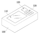
도 1은 본 발명의 일 실시예에 따른 스캐너를 나타낸 사시도이고, 도 2는 도 1의 스캐너의 내부 구성을 간략히 보여주는 사시도이며, 도 3은 도 1의 스캐너의 내부 구성을 간략하게 보이는 개략도이다.1 is a perspective view illustrating a scanner according to an embodiment of the present invention, FIG. 2 is a perspective view briefly showing an internal configuration of the scanner of FIG. 1, and FIG. 3 is a schematic view schematically showing an internal configuration of the scanner of FIG. 1.
도 1에 도시된 바와 같이 하우징(100)의 일면, 예를 들어 상면에는 반사 특성이 다른 두 개의 투명체가 나란하게 배치된다. 상기 하우징(100)의 상면 좌측에 배치되는 제1 투명체로는 도 1 내지 도 3에 도시된 바와 같이 유리판(110)이 사용되고, 상기 하우징(100)의 상면 우측에 배치되는 제2 투명체로는 다각, 예를 들어 삼각 프리즘(120)이 사용될 수 있다.As shown in FIG. 1, two transparent bodies having different reflection characteristics are disposed side by side on one surface, for example, an upper surface of the
상기 하우징(100)의 내부에는 광원(210)이 배치된다. 상기 광원(210)은 상기 제1 및 제2 투명체, 즉 상기 유리판(110)과 상기 프리즘(120)을 향해 빛을 발한다. 상기 광원(210)으로는 예를 들어 LED(Light Emitting Diode)가 사용될 수 있다.The
상기 하우징(100)의 내부에는 상기 제1 및 제2 투명체의 인근, 예를 들어 아래 공간을 왕복 이동할 수 있는 캐리어(150)가 구비된다. 상기 캐리어(150)는 도 2 및 도 3에 도시된 바와 같이 위에서 보았을 때 상기 제1 및 제2 투명체, 즉 상기 유리판(110)과 상기 프리즘(120)의 사이에 배치된다. 상기 캐리어(150)의 왕복 이동은 벨트(151) 및 구동 모터(153)에 의해 이루어지는데, 상기 캐리어(150)가 안정적으로 왕복 운동할 수 있도록 가이드 바(155)가 안내해준다.The
상기 캐리어(150)가 최초 위치, 즉 상기 유리판(110)과 상기 프리즘(120)의 사이에 있을 때 상기 구동 모터(153)가 일방향으로 회전하면 상기 캐리어(150)는 상기 유리판(110) 쪽으로 이동한다. 그리고, 상기 구동 모터(153)가 상기 일방향과 반대 방향인 타방향으로 회전하면 상기 캐리어(150)는 다시 최초 위치로 복귀한다. 상기 캐리어(150)가 최초 위치에 있을 때 상기 구동 모터(153)가 타방향으로 회전하면 상기 캐리어(150)는 상기 프리즘(120) 쪽으로 이동한다. 그리고, 상기 구동 모터(153)가 다시 일방향으로 회전하면 상기 캐리어(150)는 다시 최초 위치로 복귀한다.When the
위와 같이 상기 캐리어(150)는, 상기 구동 모터(153)의 회전 방향에 따라서, 상기 제1 또는 제2 투명체, 즉 상기 유리판(110) 또는 상기 프리즘(120)의 인근 공간, 예를 들어 아래 공간을 왕복 운동할 수 있게 된다.As described above, the
상기 캐리어(150)에는 상기 제1 또는 제2 투명체, 즉 상기 유리판(110) 또는 상기 프리즘(120) 위에 놓인 대상물을 스캔하는 이미지 센서(220)가 장착된다. 여기서, 상기 광원(210) 또한 상기 캐리어(150)에 장착될 수 있다. 따라서, 상기 구동 모터(153)가 작동하면, 상기 캐리어(150)에 장착된 이미지 센서(220) 및 광원(210)이 함께 상기 제1 또는 제2 투명체 쪽으로 이동하게 된다.The
상기 이미지 센서(220)로는 예를 들어 CCD(Charged Coupled Device)나 CIS(Contact Image Sensor) 등이 사용될 수 있다. 상기 이미지 센서(220)는 고가이기 때문에, 소형으로 제작되어 상기 캐리어(150)와 함께 움직이면서 상기 제1 또는 제2 투명체 위에 놓인 스캔 대상물을 스캔하도록 구성되는 것이다.As the
상기 이미지 센서(220)는 상기 광원(210)에서 발산된 후 상기 제1 또는 제2 투명체, 즉 상기 유리판(110) 또는 상기 프리즘(120)을 통과한 빛을 받아서 전기적 신호로 변환한다. 상기 이미지 센서(220)에서 출력되는 전기 신호는 이미지 처리부(230)에서 디지털 신호인 '0'과 '1'로 변환된다. 이러한 이미지 처리부(230)는 디지털 신호를 처리하는 디지털 신호 처리 프로세서(DSP: Digital Signal Processor) 및 버퍼 메모리(Buffer Memory)를 포함하여 이루어지며, 도 2 및 도 3에 도시된 바와 같이 상기 캐리어(150)에 장착될 수 있다.The
상기 이미지 처리부(230)에서 변환된 디지털 신호는 비록 도시하지는 않았지만 데이터 전송부에 의해서 상기 스캐너 내부에 마련된 제어부(미도시)나 상기 스캐너가 연결된 컴퓨터(미도시)의 제어부(미도시)로 전송된다. 본 발명에 따른 스캐너가 스캔 정보를 직접 처리하여 가공하여 저장하거나 외부로 출력할 수 있도록 구성되는 경우, 상기 스캐너에는 이를 위한 별도의 제어부(미도시)가 마련되며, 이는 상기 하우징(100)의 외면에 마련된 컨트롤 패널(130)을 통해 적절히 제어될 수 있을 것이다. 그러나, 그렇지 않은 경우, 상기 이미지 처리부(230)에서 변환된 디지털 신호는 상기 스캐너가 연결된 별도의 컴퓨터의 제어부로 전송된다.Although not shown, the digital signal converted by the
한편, 본 발명의 일 실시예에 따른 스캐너에서 상기 제1 및 제2 투명체는 스 캔 대상물과 접촉하는 각 면이 서로 다른 반사 특성을 가지도록 배치된다. 이에 의해서, 본 발명의 일 실시예에 따른 스캐너는, 표면의 반사 특성이 서로 다른 두 종류의 스캔 대상물, 예를 들어 종이와 사진이나 지문과 도장을 각각 효과적으로 스캔할 수 있게 된다. 도 4 내지 8에는 제1 및 제2 투명체가 서로 다른 두 종류의 스캔 대상물을 스캔하는 원리 및 구조가 개략적으도 도시되어 있는데, 이하에서는 이들 도면을 참조하여 좀더 상세히 설명한다.On the other hand, in the scanner according to an embodiment of the present invention, the first and second transparent bodies are disposed such that each surface in contact with the scan object has different reflection characteristics. As a result, the scanner according to an embodiment of the present invention can effectively scan two kinds of scanning objects having different reflection characteristics of the surface, for example, paper, photographs, fingerprints, and paints. 4 to 8 schematically illustrate a principle and a structure of scanning two types of scan objects different from each other by the first and second transparent bodies, which will be described below in more detail with reference to these drawings.
참고로, 도 4는 도 1의 스캐너에서 이미지 센서가 유리판 위에 놓여진 종이를 스캔하는 모습을 나타낸 개략도이고, 도 5는 도 1의 스캐너에서 이미지 센서가 프리즘 위에 접촉된 손가락의 지문을 스캔하는 모습을 나타낸 개략도이며, 도 6은 도 5에서 손가락과 프리즘의 접촉 부위에서 광원의 빛이 반사되는 특성을 보여주는 개략도이다. 그리고, 도 7은 도 1의 스캐너에서 프리즘과 이미지 센서 사이에 반사판이 구비된 예를 나타낸 개략도이고, 도 8은 도 1의 스캐너에서 도 5 및 도 7의 프리즘 대신 적용될 수 있는 프레넬 렌즈를 나타낸 개략도이다.For reference, FIG. 4 is a schematic view showing the image sensor scanning the paper placed on the glass plate in the scanner of FIG. 1, and FIG. 5 shows the image sensor scanning the fingerprint of the finger contacted on the prism in the scanner of FIG. FIG. 6 is a schematic view illustrating a characteristic in which light of a light source is reflected at a contact portion between a finger and a prism in FIG. 5. 7 is a schematic view illustrating an example in which a reflector is provided between a prism and an image sensor in the scanner of FIG. 1, and FIG. 8 illustrates a Fresnel lens that may be applied instead of the prisms of FIGS. 5 and 7 in the scanner of FIG. 1. Schematic diagram.
상기 제1 투명체로서 상기 하우징(100)의 상면 좌측에 배치된 유리판(110)은 도 4에 도시된 바와 같이 광원(210)에서 발산된 빛을 투과시키도록 배치된다. 상기 유리판(110)의 위에는 제1 스캔 대상물(10)이 올려질 수 있는데, 상기 제1 스캔 대상물(10)로는 종이나 사진 및 주민등록증 등의 신분증 등이 있다. 상기 종이나 사진 및 주민등록증 등은 실질적으로 평평한 표면을 가지는데, 이들의 표면에 비춰진 빛의 반사량은 표면의 명암에 따라서 달라진다.The
상기 유리판(110)의 아래에 배치된 광원(210)에서 상기 하우징(100)의 일면, 즉 상면으로 발산된 빛은 도 4의 화살표가 나타낸 바와 같이 상기 유리판(110)을 투과한 후 상기 제1 스캔 대상물(10)의 표면에 전달된다. 상기 제1 스캔 대상물(10)의 표면에 도달한 빛은 상기 제1 스캔 대상물(10)의 명암에 따라서 반사되는 양이 달라진다. 상기 제1 스캔 대상물(10)의 표면에서 반사된 빛은 다시 상기 유리판(110)을 통과한 후 상기 이미지 센서(220)로 전달된다. 상기 이미지 센서(220)는 상기 유리판(110)을 통과한 빛을 받아서 전기 신호를 출력하고, 출력된 전기 신호는 상기 이미지 처리부(230)로 전달되어 디지털 신호로 변화된다.Light emitted from the
위에서 설명한 바와 같이 종이나 사진 및 주민등록증 등 신분증과 같은 특성을 가진 제1 스캔 대상물(10)은 제1 투명체, 즉 유리판(110) 위에 올려놓고 효과적으로 스캔할 수 있다. 그러나, 손가락의 지문(21)을 상기 유리판(110)에 올려놓고 스캔하는 경우, 상기 손가락에 비춰진 빛의 반사량이 크게 다르지 않기 때문에 유효한 스캔 정보를 얻을 수 없다. 이는 도장(미도시)과 같이 굴곡면을 가지는 스캔 대상물도 마찬가지이다.As described above, the
상기 제2 투명체, 즉 상기 프리즘(120)은 상기한 손가락의 지문(21)이나 도장과 같은 특성을 가지는 제2 스캔 대상물(20)을 효과적으로 스캔할 수 있도록 해준다. 도 5 및 도 6에는 상기 제2 투명체를 이용한 제2 스캔 대상물(20)의 스캔 원리가 자세히 나타나 있는데, 이하에서는 이들 도면을 참조하여 좀더 상세히 설명한다.The second transparent body, that is, the
상기 제2 투명체, 즉 상기 프리즘(120)은 상기 광원(210)에서 발산된 빛을 상기 제2 스캔 대상물(20)이 접촉하는 접촉면(121)에서 실질적으로 전반사할 수 있 도록 배치된다. 즉, 상기 프리즘(120)은 상기 광원(210)의 빛을 상기 접촉면(121)이 실질적으로 전부 반사시킬 수 있도록 배치되는 것이다. 이를 위해, 상기 프리즘(120)은 상기 광원(210)에서 발산된 빛이 상기 접촉면(121)에 임계각보다 큰 각도로 입사되도록 배치된다.The second transparent body, that is, the
상기 광원(210)에서 발산된 빛은 도 5에 도시된 바와 같이 상기 프리즘(120)의 하면(123)을 통해 상기 프리즘(120)의 내부로 입사되고, 상기 접촉면(121)에서 전반사된다. 그리고, 상기 접촉면(121)에서 전반사된 빛은 상기 프리즘(120)의 한 면을 이루고 있는 반사면(122)으로 입사되는데, 상기 반사면(122)은 상기 접촉면(121)에서 반사된 빛이 임계각보다 큰 각도로 입사되도록 배치되므로 상기 반사면(122)에서도 도 5에 도시된 바와 같이 실질적인 전반사가 일어난다. 따라서, 상기 광원(210)에서 프리즘(120)의 하면(123)으로 입사된 빛은 상기 접촉면(121)과 상기 반사면(122)을 거쳐 상기 이미지 센서(220)로 전달된다.As shown in FIG. 5, the light emitted from the
그런데, 상기 접촉면(121)에 손가락의 지문(21) 등 제2 스캔 대상물(20)이 접촉되면, 도 6에 도시된 바와 같이 상기 제2 스캔 대상물(20)과 접촉면(121)이 접촉된 접촉 부위 'A'는 굴절률이 변하게 되어 입사광이 전반사되는 조건을 상실한다. 따라서, 도 6의 화살표가 보여주는 바와 같이, 상기 프리즘(120)의 접촉면(121)으로 입사된 광원(210)의 빛은 상기 접촉면(121)과 접촉하지 않는 골(23) 부분에서는 전반사되지만, 상기 접촉면(121)과 접촉하는 지문(21)의 융선 부분에서는 전반사되지 못한다. 그러므로, 상기 프리즘(120)의 접촉면(121)과 접촉한 지문(21)이 어둡게 관측되어 지문(21)의 형상이 선명하게 나타나게 되며, 따라서 상 기 이미지 센서(220)가 지문(21)의 형상을 효과적으로 읽어 들일 수 있게 된다. 이는 도장에서도 마찬가지 이다.However, when the
상기 프리즘(120)과 상기 이미지 센서(220)의 사이에는 도 5에 도시된 바와 같이 집광 렌즈(240)가 배치될 수 있다. 상기 집광 렌즈(240)는 상기 프리즘(120)을 통과한 후 상기 이미지 센서(220)로 진행하는 빛을 집광시켜 상기 이미지 센서(220)에 결상시킴으로써 상기 이미지 센서(220)가 상기 지문(21)의 형상을 정확히 읽을 수 있게 해준다.A
한편, 본 발명에 따른 스캐너에는 도 7에 도시된 바와 같이 상기 프리즘(120)을 통과한 빛의 이동 경로를 변경하여 상기 이미지 센서(220)로 전달하는 반사판(250)이 더 구비될 수도 있다. 상기 반사판(250)은 상기 프리즘(120)을 통과한 빛이 상기 이미지 센서(220)로 직접 전달되기 어렵게 구성된 경우, 도 7에 도시된 바와 같이 상기 빛의 이동 경로상에 적어도 하나가 배치되어 빛이 상기 이미지 센서(220)로 입사되도록 빛의 이동 경로를 변경시킨다. 참고로, 미설명 부호 260은 집광 렌즈 등 빛을 상기 이미지 센서(200)에 효과적으로 결상시키기 위한 결상 수단이다.On the other hand, the scanner according to the present invention may further include a reflecting
위에서는 상기 제2 투명체로서 다각 프리즘(120)이 사용된 예가 설명되었다. 그러나, 본 발명은 이에 국한되지만은 않는다. 다른 예로, 도 8에 도시된 바와 같이 상기 제2 투명체로서 프레넬 렌즈(120a)가 사용될 수도 있다. 상기 프레넬 렌즈(120a)은 도 8에 도시된 바와 같이 제2 스캔 대상물(20)이 접촉하는 평평한 접촉면(121a) 및 상기 접촉면(121a)의 반대면을 이루며 다수의 프리즘 띠(126a)를 가지 는 프레넬 렌즈면(123a)을 포함하여 이루어진다.In the above, an example in which the
상기 프레넬 렌즈(120a)의 상기 접촉면(121a)은 각 프리즘 띠(126a)의 하면을 통해 입사된 빛이 임계각보다 큰 각으로 입사되도록 배치된다. 따라서, 각 프리즘 띠(126a)를 통해 상기 프레넬 렌즈(120a)의 내부로 입사된 빛은 도 8에 도시된 바와 같이 상기 접촉면(121a)에서 전반사된다. 상기 접촉면(121a)에 지문(21) 등의 제2 스캔 대상물(20)이 접촉하면 해당 접촉 부위는 전반사 조건을 상실하므로 전반사가 일어나지 못한다. 따라서, 상기 프레넬 렌즈(120a)는 도 5 내지 도 7을 참조하여 설명한 바와 동일한 원리로 지문(21) 등을 효과적으로 스캔할 수 있게 해준다.The
본 발명에 따른 스캐너에서 상기 제1 투명체는 위에서 설명한 바와 같이 종이나 사진 또는 주민등록증 등의 신분증을 스캔할 수 있도록 제공되고, 상기 제2 투명체는 지문이나 도장 등을 스캔할 수 있도록 제공된다. 따라서, 상기 제2 투명체, 즉 상기 유리판(110)은 주민등록증 등의 신분증을 스캔할 수 있는 크기나 그 이상의 크기로 형성되고, 상기 제1 투명체, 즉 상기 프리즘(120)이나 상기 프레넬 렌즈(120a)는 상기 지문(21) 또는 도장을 스캔할 수 있는 정도로 상기 제1 투명체보다 작게 형성된다.In the scanner according to the present invention, the first transparent body is provided to scan an ID card such as a paper, a photo, or a social security card as described above, and the second transparent body is provided to scan a fingerprint or a seal. Accordingly, the second transparent body, that is, the
사용자는 위와 같이 구성된 본 발명에 따른 스캐너를 이용하여 주민등록증 등의 제1 스캔 대상물(10)과 지문 등의 제2 스캔 대상물(20)을 선택적으로 스캔할 수 있다. 예를 들어, 상기 제1 투명체, 즉 상기 유리판(110) 위에 주민등록증 등을 올려놓고 상기 하우징(100)의 외면에 제공된 상기 컨트롤 패널(130)을 조작하 면, 상기 캐리어(150)가 상기 유리판(110) 쪽으로 이동하면서 상기 이미지 센서(220)가 상기 유리판(110) 위의 주민등록증을 스캔하게 된다. 스캔이 완료되면 상기 캐리어(150)는 최초 위치로 복귀한다.The user may selectively scan the
다른 예로, 상기 제2 투명체, 즉 상기 프리즘(120)이나 상기 프레넬 렌즈(120a) 위에 손가락이나 도장을 접촉시키고 상기 컨트롤 패널(130)을 조작하면, 상기 캐리어(150)가 상기 프리즘(120)이나 상기 프레넬 렌즈(120a) 쪽으로 이동하면서 상기 이미지 센서(220)가 지문 또는 도장을 스캔하게 된다. 스캔이 완료되면 상기 캐리어(150)는 다시 최초 위치로 복귀한다.As another example, when a finger or a paint is placed on the second transparent body, that is, the
위와 같이 상기 제1 투명체 또는 제2 투명체 위에 올려진 스캔 대상물을 스캔한 정보는 상기 이미지 처리부(230)에 의해 디지털 신호로 변환된 후 상기 데이터 전송부에 의해 제어부(미도시)로 전송된다. 상기 제어부로 전송된 스캔 정보는 그대로 또는 가공되어 저장 장치에 저장되거나, 확인 및 인증 등의 목적으로 사용될 수 있다. 따라서, 본 발명에 따른 스캐너는, 신분증과 지문이나 도장 등을 각각 스캔하여 신분 정보 등을 획득하고, 획득된 신분 정보를 신원을 확인하거나 인증하는데 활용하는 분야에 매우 유용하게 활용될 수 있을 것이다.The information scanned by the scan object on the first transparent body or the second transparent body as described above is converted into a digital signal by the
이상과 같이 본 발명에 따른 바람직한 실시예를 살펴보았으며, 앞서 설명된 실시예 이외에도 본 발명이 그 취지나 범주에서 벗어남이 없이 다른 특정 형태로 구체화 될 수 있다는 사실은 해당 기술에 통상의 지식을 가진 이들에게는 자명한 것이다. 그러므로, 상술된 실시예는 제한적인 것이 아니라 예시적인 것으로 여겨져야 하고, 이에 따라 본 발명은 상술한 설명에 한정되지 않고 첨부된 청구항의 범 주 및 그 동등 범위 내에서 변경될 수도 있다.As described above, the preferred embodiments of the present invention have been described, and the fact that the present invention can be embodied in other specific forms in addition to the above-described embodiments without departing from the spirit or scope thereof has ordinary skill in the art. It is obvious to them. Therefore, the above-described embodiments should be regarded as illustrative rather than restrictive, and thus, the present invention is not limited to the above description and may be modified within the scope of the appended claims and their equivalents.
도 1은 본 발명의 일 실시예에 따른 스캐너를 나타낸 사시도;1 is a perspective view of a scanner according to an embodiment of the present invention;
도 2는 도 1의 스캐너의 내부 구성을 간략히 보여주는 사시도;2 is a perspective view briefly showing an internal configuration of the scanner of FIG. 1;
도 3은 도 1의 스캐너의 내부 구성을 간략하게 보이는 개략도;3 is a schematic view schematically showing the internal configuration of the scanner of FIG. 1;
도 4는 도 1의 스캐너에서 이미지 센서가 유리판 위에 놓여진 종이를 스캔하는 모습을 나타낸 개략도;4 is a schematic view showing a state in which the image sensor scans the paper placed on the glass plate in the scanner of FIG.
도 5는 도 1의 스캐너에서 이미지 센서가 프리즘 위에 접촉된 손가락의 지문을 스캔하는 모습을 나타낸 개략도;FIG. 5 is a schematic diagram showing an image sensor scanning a fingerprint of a finger in contact with a prism in the scanner of FIG. 1; FIG.
도 6은 도 5에서 손가락과 프리즘의 접촉 부위에서 광원의 빛이 반사되는 특성을 보여주는 개략도;FIG. 6 is a schematic view illustrating a characteristic in which light of a light source is reflected at a contact portion between a finger and a prism in FIG. 5;
도 7은 도 1의 스캐너에서 프리즘과 이미지 센서 사이에 반사판이 구비된 예를 나타낸 개략도; 및7 is a schematic view showing an example in which a reflector is provided between a prism and an image sensor in the scanner of FIG. 1; And
도 8은 도 1의 스캐너에서 도 5 및 도 7의 프리즘 대신 적용될 수 있는 프레넬 렌즈를 나타낸 개략도이다.8 is a schematic diagram illustrating a Fresnel lens that may be applied in place of the prism of FIGS. 5 and 7 in the scanner of FIG. 1.
<도면의 주요 부분에 대한 부호 설명> <Description of the symbols for the main parts of the drawings>
10: 제1 스캔 대상물 20: 제2 스캔 대상물10: first scan object 20: second scan object
100: 하우징 110: 유리판100: housing 110: glass plate
120: 프리즘 120a: 프레넬 렌즈120:
121, 121a: 접촉면 150: 캐리어121, 121a: contact surface 150: carrier
210: 광원 220: 이미지 렌즈210: light source 220: image lens
230: 이미지 처리부 240: 집광 렌즈230: image processing unit 240: condensing lens
250: 반사판 260: 결상 수단250: reflector 260: imaging means
Claims (10)
Priority Applications (1)
| Application Number | Priority Date | Filing Date | Title |
|---|---|---|---|
| KR1020080012223A KR20090086768A (en) | 2008-02-11 | 2008-02-11 | scanner |
Applications Claiming Priority (1)
| Application Number | Priority Date | Filing Date | Title |
|---|---|---|---|
| KR1020080012223A KR20090086768A (en) | 2008-02-11 | 2008-02-11 | scanner |
Publications (1)
| Publication Number | Publication Date |
|---|---|
| KR20090086768A true KR20090086768A (en) | 2009-08-14 |
Family
ID=41205998
Family Applications (1)
| Application Number | Title | Priority Date | Filing Date |
|---|---|---|---|
| KR1020080012223A Ceased KR20090086768A (en) | 2008-02-11 | 2008-02-11 | scanner |
Country Status (1)
| Country | Link |
|---|---|
| KR (1) | KR20090086768A (en) |
Cited By (2)
| Publication number | Priority date | Publication date | Assignee | Title |
|---|---|---|---|---|
| WO2012096477A3 (en) * | 2011-01-13 | 2012-11-22 | Lee Young-Suk | Apparatus for scanning an image captured by a camera using a total reflection prism, and method for controlling same |
| KR102532234B1 (en) * | 2022-10-31 | 2023-05-15 | 오성시스템 주식회사 | Identification apparatus for elections |
-
2008
- 2008-02-11 KR KR1020080012223A patent/KR20090086768A/en not_active Ceased
Cited By (2)
| Publication number | Priority date | Publication date | Assignee | Title |
|---|---|---|---|---|
| WO2012096477A3 (en) * | 2011-01-13 | 2012-11-22 | Lee Young-Suk | Apparatus for scanning an image captured by a camera using a total reflection prism, and method for controlling same |
| KR102532234B1 (en) * | 2022-10-31 | 2023-05-15 | 오성시스템 주식회사 | Identification apparatus for elections |
Similar Documents
| Publication | Publication Date | Title |
|---|---|---|
| US8600196B2 (en) | Optical scanners, such as hand-held optical scanners | |
| KR100611135B1 (en) | Method and apparatus for illuminating a fingerprint | |
| JP3859729B2 (en) | Optical scanner particularly useful as an electronic translator | |
| CN1209881A (en) | Non-flat surface image transmission device | |
| US8245922B2 (en) | Method and device for identifying and authenticating objects | |
| CN101647029A (en) | Obtain the apparatus and method of fingerprint | |
| US20040035937A1 (en) | Code reader and code reading method for color image | |
| EP1112522A1 (en) | Variable focus optical system | |
| CN1666223A (en) | Improved bar code scanner and method | |
| WO1998018098A1 (en) | Camera for decoding machine readable images having diffuser | |
| US7081951B2 (en) | Palm print scanner and methods | |
| JPWO2006077718A1 (en) | Lens array and image sensor having lens array | |
| CN101470545A (en) | Mouse | |
| KR20090086768A (en) | scanner | |
| US8752767B2 (en) | Illumination system with prism for use in imaging scanner | |
| US20030201327A1 (en) | Variable focal length imaging device | |
| KR20090086769A (en) | scanner | |
| US7180643B2 (en) | Live print scanner with holographic imaging a different magnifications | |
| JP6765339B2 (en) | Image sensor unit, paper leaf identification device, reader and image forming device | |
| US20120051602A1 (en) | Imaging a print abberation | |
| US7221489B2 (en) | Live print scanner with holographic platen | |
| EP1247395A1 (en) | Document reading apparatus having a waveguide formed in a substrate | |
| KR100347269B1 (en) | Fingerprint recognition device | |
| US20040146188A1 (en) | Contoured prism print scanners | |
| KR100958174B1 (en) | Scanning device |
Legal Events
| Date | Code | Title | Description |
|---|---|---|---|
| A201 | Request for examination | ||
| PA0109 | Patent application |
St.27 status event code: A-0-1-A10-A12-nap-PA0109 |
|
| PA0201 | Request for examination |
St.27 status event code: A-1-2-D10-D11-exm-PA0201 |
|
| R18-X000 | Changes to party contact information recorded |
St.27 status event code: A-3-3-R10-R18-oth-X000 |
|
| D13-X000 | Search requested |
St.27 status event code: A-1-2-D10-D13-srh-X000 |
|
| D14-X000 | Search report completed |
St.27 status event code: A-1-2-D10-D14-srh-X000 |
|
| PG1501 | Laying open of application |
St.27 status event code: A-1-1-Q10-Q12-nap-PG1501 |
|
| E902 | Notification of reason for refusal | ||
| PE0902 | Notice of grounds for rejection |
St.27 status event code: A-1-2-D10-D21-exm-PE0902 |
|
| E13-X000 | Pre-grant limitation requested |
St.27 status event code: A-2-3-E10-E13-lim-X000 |
|
| P11-X000 | Amendment of application requested |
St.27 status event code: A-2-2-P10-P11-nap-X000 |
|
| P13-X000 | Application amended |
St.27 status event code: A-2-2-P10-P13-nap-X000 |
|
| E601 | Decision to refuse application | ||
| PE0601 | Decision on rejection of patent |
St.27 status event code: N-2-6-B10-B15-exm-PE0601 |
|
| R18-X000 | Changes to party contact information recorded |
St.27 status event code: A-3-3-R10-R18-oth-X000 |
|
| PN2301 | Change of applicant |
St.27 status event code: A-3-3-R10-R13-asn-PN2301 St.27 status event code: A-3-3-R10-R11-asn-PN2301 |
|
| P22-X000 | Classification modified |
St.27 status event code: A-2-2-P10-P22-nap-X000 |
|
| P22-X000 | Classification modified |
St.27 status event code: A-2-2-P10-P22-nap-X000 |
|
| PN2301 | Change of applicant |
St.27 status event code: A-3-3-R10-R13-asn-PN2301 St.27 status event code: A-3-3-R10-R11-asn-PN2301 |
|
| R18-X000 | Changes to party contact information recorded |
St.27 status event code: A-3-3-R10-R18-oth-X000 |
|
| R18-X000 | Changes to party contact information recorded |
St.27 status event code: A-3-3-R10-R18-oth-X000 |
|
| P22-X000 | Classification modified |
St.27 status event code: A-2-2-P10-P22-nap-X000 |
|
| R18 | Changes to party contact information recorded |
Free format text: ST27 STATUS EVENT CODE: A-3-3-R10-R18-OTH-X000 (AS PROVIDED BY THE NATIONAL OFFICE) |
|
| R18-X000 | Changes to party contact information recorded |
St.27 status event code: A-3-3-R10-R18-oth-X000 |