KR20070112567A - Handheld terminal - Google Patents
Handheld terminal Download PDFInfo
- Publication number
- KR20070112567A KR20070112567A KR1020060045627A KR20060045627A KR20070112567A KR 20070112567 A KR20070112567 A KR 20070112567A KR 1020060045627 A KR1020060045627 A KR 1020060045627A KR 20060045627 A KR20060045627 A KR 20060045627A KR 20070112567 A KR20070112567 A KR 20070112567A
- Authority
- KR
- South Korea
- Prior art keywords
- display
- portable terminal
- light emission
- information
- plate
- Prior art date
- Legal status (The legal status is an assumption and is not a legal conclusion. Google has not performed a legal analysis and makes no representation as to the accuracy of the status listed.)
- Ceased
Links
Images


Classifications
-
- H—ELECTRICITY
- H04—ELECTRIC COMMUNICATION TECHNIQUE
- H04M—TELEPHONIC COMMUNICATION
- H04M1/00—Substation equipment, e.g. for use by subscribers
- H04M1/72—Mobile telephones; Cordless telephones, i.e. devices for establishing wireless links to base stations without route selection
- H04M1/724—User interfaces specially adapted for cordless or mobile telephones
- H04M1/72403—User interfaces specially adapted for cordless or mobile telephones with means for local support of applications that increase the functionality
- H04M1/72427—User interfaces specially adapted for cordless or mobile telephones with means for local support of applications that increase the functionality for supporting games or graphical animations
-
- H—ELECTRICITY
- H04—ELECTRIC COMMUNICATION TECHNIQUE
- H04B—TRANSMISSION
- H04B1/00—Details of transmission systems, not covered by a single one of groups H04B3/00 - H04B13/00; Details of transmission systems not characterised by the medium used for transmission
- H04B1/38—Transceivers, i.e. devices in which transmitter and receiver form a structural unit and in which at least one part is used for functions of transmitting and receiving
- H04B1/40—Circuits
-
- G—PHYSICS
- G02—OPTICS
- G02F—OPTICAL DEVICES OR ARRANGEMENTS FOR THE CONTROL OF LIGHT BY MODIFICATION OF THE OPTICAL PROPERTIES OF THE MEDIA OF THE ELEMENTS INVOLVED THEREIN; NON-LINEAR OPTICS; FREQUENCY-CHANGING OF LIGHT; OPTICAL LOGIC ELEMENTS; OPTICAL ANALOGUE/DIGITAL CONVERTERS
- G02F1/00—Devices or arrangements for the control of the intensity, colour, phase, polarisation or direction of light arriving from an independent light source, e.g. switching, gating or modulating; Non-linear optics
- G02F1/01—Devices or arrangements for the control of the intensity, colour, phase, polarisation or direction of light arriving from an independent light source, e.g. switching, gating or modulating; Non-linear optics for the control of the intensity, phase, polarisation or colour
- G02F1/13—Devices or arrangements for the control of the intensity, colour, phase, polarisation or direction of light arriving from an independent light source, e.g. switching, gating or modulating; Non-linear optics for the control of the intensity, phase, polarisation or colour based on liquid crystals, e.g. single liquid crystal display cells
- G02F1/133—Constructional arrangements; Operation of liquid crystal cells; Circuit arrangements
- G02F1/1333—Constructional arrangements; Manufacturing methods
- G02F1/1335—Structural association of cells with optical devices, e.g. polarisers or reflectors
- G02F1/133509—Filters, e.g. light shielding masks
- G02F1/133512—Light shielding layers, e.g. black matrix
-
- G—PHYSICS
- G06—COMPUTING OR CALCULATING; COUNTING
- G06F—ELECTRIC DIGITAL DATA PROCESSING
- G06F1/00—Details not covered by groups G06F3/00 - G06F13/00 and G06F21/00
- G06F1/16—Constructional details or arrangements
- G06F1/1601—Constructional details related to the housing of computer displays, e.g. of CRT monitors, of flat displays
- G06F1/1607—Arrangements to support accessories mechanically attached to the display housing
- G06F1/1609—Arrangements to support accessories mechanically attached to the display housing to support filters or lenses
-
- G—PHYSICS
- G06—COMPUTING OR CALCULATING; COUNTING
- G06F—ELECTRIC DIGITAL DATA PROCESSING
- G06F1/00—Details not covered by groups G06F3/00 - G06F13/00 and G06F21/00
- G06F1/16—Constructional details or arrangements
- G06F1/1613—Constructional details or arrangements for portable computers
- G06F1/1615—Constructional details or arrangements for portable computers with several enclosures having relative motions, each enclosure supporting at least one I/O or computing function
- G06F1/1616—Constructional details or arrangements for portable computers with several enclosures having relative motions, each enclosure supporting at least one I/O or computing function with folding flat displays, e.g. laptop computers or notebooks having a clamshell configuration, with body parts pivoting to an open position around an axis parallel to the plane they define in closed position
-
- G—PHYSICS
- G06—COMPUTING OR CALCULATING; COUNTING
- G06F—ELECTRIC DIGITAL DATA PROCESSING
- G06F1/00—Details not covered by groups G06F3/00 - G06F13/00 and G06F21/00
- G06F1/16—Constructional details or arrangements
- G06F1/1613—Constructional details or arrangements for portable computers
- G06F1/1633—Constructional details or arrangements of portable computers not specific to the type of enclosures covered by groups G06F1/1615 - G06F1/1626
- G06F1/1637—Details related to the display arrangement, including those related to the mounting of the display in the housing
- G06F1/1647—Details related to the display arrangement, including those related to the mounting of the display in the housing including at least an additional display
-
- G—PHYSICS
- G09—EDUCATION; CRYPTOGRAPHY; DISPLAY; ADVERTISING; SEALS
- G09G—ARRANGEMENTS OR CIRCUITS FOR CONTROL OF INDICATING DEVICES USING STATIC MEANS TO PRESENT VARIABLE INFORMATION
- G09G5/00—Control arrangements or circuits for visual indicators common to cathode-ray tube indicators and other visual indicators
-
- H—ELECTRICITY
- H04—ELECTRIC COMMUNICATION TECHNIQUE
- H04M—TELEPHONIC COMMUNICATION
- H04M1/00—Substation equipment, e.g. for use by subscribers
- H04M1/02—Constructional features of telephone sets
- H04M1/0202—Portable telephone sets, e.g. cordless phones, mobile phones or bar type handsets
-
- G—PHYSICS
- G02—OPTICS
- G02F—OPTICAL DEVICES OR ARRANGEMENTS FOR THE CONTROL OF LIGHT BY MODIFICATION OF THE OPTICAL PROPERTIES OF THE MEDIA OF THE ELEMENTS INVOLVED THEREIN; NON-LINEAR OPTICS; FREQUENCY-CHANGING OF LIGHT; OPTICAL LOGIC ELEMENTS; OPTICAL ANALOGUE/DIGITAL CONVERTERS
- G02F1/00—Devices or arrangements for the control of the intensity, colour, phase, polarisation or direction of light arriving from an independent light source, e.g. switching, gating or modulating; Non-linear optics
- G02F1/01—Devices or arrangements for the control of the intensity, colour, phase, polarisation or direction of light arriving from an independent light source, e.g. switching, gating or modulating; Non-linear optics for the control of the intensity, phase, polarisation or colour
- G02F1/13—Devices or arrangements for the control of the intensity, colour, phase, polarisation or direction of light arriving from an independent light source, e.g. switching, gating or modulating; Non-linear optics for the control of the intensity, phase, polarisation or colour based on liquid crystals, e.g. single liquid crystal display cells
- G02F1/133—Constructional arrangements; Operation of liquid crystal cells; Circuit arrangements
- G02F1/1333—Constructional arrangements; Manufacturing methods
- G02F1/1335—Structural association of cells with optical devices, e.g. polarisers or reflectors
- G02F1/13356—Structural association of cells with optical devices, e.g. polarisers or reflectors characterised by the placement of the optical elements
- G02F1/133562—Structural association of cells with optical devices, e.g. polarisers or reflectors characterised by the placement of the optical elements on the viewer side
-
- G—PHYSICS
- G06—COMPUTING OR CALCULATING; COUNTING
- G06F—ELECTRIC DIGITAL DATA PROCESSING
- G06F2200/00—Indexing scheme relating to G06F1/04 - G06F1/32
- G06F2200/16—Indexing scheme relating to G06F1/16 - G06F1/18
- G06F2200/161—Indexing scheme relating to constructional details of the monitor
- G06F2200/1612—Flat panel monitor
-
- G—PHYSICS
- G09—EDUCATION; CRYPTOGRAPHY; DISPLAY; ADVERTISING; SEALS
- G09G—ARRANGEMENTS OR CIRCUITS FOR CONTROL OF INDICATING DEVICES USING STATIC MEANS TO PRESENT VARIABLE INFORMATION
- G09G2320/00—Control of display operating conditions
- G09G2320/06—Adjustment of display parameters
-
- G—PHYSICS
- G09—EDUCATION; CRYPTOGRAPHY; DISPLAY; ADVERTISING; SEALS
- G09G—ARRANGEMENTS OR CIRCUITS FOR CONTROL OF INDICATING DEVICES USING STATIC MEANS TO PRESENT VARIABLE INFORMATION
- G09G2320/00—Control of display operating conditions
- G09G2320/06—Adjustment of display parameters
- G09G2320/0626—Adjustment of display parameters for control of overall brightness
-
- G—PHYSICS
- G09—EDUCATION; CRYPTOGRAPHY; DISPLAY; ADVERTISING; SEALS
- G09G—ARRANGEMENTS OR CIRCUITS FOR CONTROL OF INDICATING DEVICES USING STATIC MEANS TO PRESENT VARIABLE INFORMATION
- G09G2340/00—Aspects of display data processing
- G09G2340/04—Changes in size, position or resolution of an image
- G09G2340/045—Zooming at least part of an image, i.e. enlarging it or shrinking it
-
- G—PHYSICS
- G09—EDUCATION; CRYPTOGRAPHY; DISPLAY; ADVERTISING; SEALS
- G09G—ARRANGEMENTS OR CIRCUITS FOR CONTROL OF INDICATING DEVICES USING STATIC MEANS TO PRESENT VARIABLE INFORMATION
- G09G2340/00—Aspects of display data processing
- G09G2340/12—Overlay of images, i.e. displayed pixel being the result of switching between the corresponding input pixels
-
- G—PHYSICS
- G09—EDUCATION; CRYPTOGRAPHY; DISPLAY; ADVERTISING; SEALS
- G09G—ARRANGEMENTS OR CIRCUITS FOR CONTROL OF INDICATING DEVICES USING STATIC MEANS TO PRESENT VARIABLE INFORMATION
- G09G2340/00—Aspects of display data processing
- G09G2340/14—Solving problems related to the presentation of information to be displayed
-
- G—PHYSICS
- G09—EDUCATION; CRYPTOGRAPHY; DISPLAY; ADVERTISING; SEALS
- G09G—ARRANGEMENTS OR CIRCUITS FOR CONTROL OF INDICATING DEVICES USING STATIC MEANS TO PRESENT VARIABLE INFORMATION
- G09G3/00—Control arrangements or circuits, of interest only in connection with visual indicators other than cathode-ray tubes
- G09G3/001—Control arrangements or circuits, of interest only in connection with visual indicators other than cathode-ray tubes using specific devices not provided for in groups G09G3/02 - G09G3/36, e.g. using an intermediate record carrier such as a film slide; Projection systems; Display of non-alphanumerical information, solely or in combination with alphanumerical information, e.g. digital display on projected diapositive as background
-
- H—ELECTRICITY
- H04—ELECTRIC COMMUNICATION TECHNIQUE
- H04M—TELEPHONIC COMMUNICATION
- H04M1/00—Substation equipment, e.g. for use by subscribers
- H04M1/02—Constructional features of telephone sets
- H04M1/0202—Portable telephone sets, e.g. cordless phones, mobile phones or bar type handsets
- H04M1/026—Details of the structure or mounting of specific components
- H04M1/0266—Details of the structure or mounting of specific components for a display module assembly
-
- H—ELECTRICITY
- H04—ELECTRIC COMMUNICATION TECHNIQUE
- H04N—PICTORIAL COMMUNICATION, e.g. TELEVISION
- H04N7/00—Television systems
- H04N7/14—Systems for two-way working
- H04N7/141—Systems for two-way working between two video terminals, e.g. videophone
- H04N7/142—Constructional details of the terminal equipment, e.g. arrangements of the camera and the display
- H04N2007/145—Handheld terminals
Landscapes
- Engineering & Computer Science (AREA)
- Physics & Mathematics (AREA)
- Theoretical Computer Science (AREA)
- Computer Hardware Design (AREA)
- General Physics & Mathematics (AREA)
- General Engineering & Computer Science (AREA)
- Human Computer Interaction (AREA)
- Signal Processing (AREA)
- Mathematical Physics (AREA)
- Nonlinear Science (AREA)
- Computer Networks & Wireless Communication (AREA)
- Chemical & Material Sciences (AREA)
- Crystallography & Structural Chemistry (AREA)
- Optics & Photonics (AREA)
- Control Of Indicators Other Than Cathode Ray Tubes (AREA)
- Devices For Indicating Variable Information By Combining Individual Elements (AREA)
- Telephone Set Structure (AREA)
Abstract
본 발명은 휴대용 단말기에 관한 것이다. 본 발명은, 적어도 하나의 몸체; 상기 적어도 하나의 몸체 중 어느 하나의 외면에 설치되고, 소정의 정보를 디스플레이하는 표시 수단; 및 상기 표시 수단 위에 설치되고, 상기 표시 수단의 면(面) 발광을 복수의 점(點) 발광으로 전환하는 발광 전환 수단을 포함하는 휴대용 단말기를 제공한다.The present invention relates to a portable terminal. The present invention, at least one body; Display means installed on an outer surface of any one of the at least one body and displaying predetermined information; And light emission switching means provided on the display means, the light emission switching means converting the surface light emission of the display means into a plurality of point light emission.
따라서, 본 발명에 의하면, 휴대용 단말기의 표시부에, 다수의 구멍이 형성된 플레이트나 반투명 필름과 같은 발광 전환 수단을 장착함으로써, 사용자에게 디지털 방식의 정보 표시뿐만 아니라 아날로그 방식의 느낌을 주는 정보 표시를 제공할 수 있다.Therefore, according to the present invention, by attaching light-emitting switching means such as a plate or translucent film having a plurality of holes formed in the display portion of the portable terminal, it is possible to provide not only digital information display but also information display giving an analog feel. can do.
Description
도 1은, 본 발명에 따른 휴대용 단말기의 외관을 개략적으로 도시한 도면.1 is a view schematically showing the appearance of a portable terminal according to the present invention;
도 2는, 플레이트가 탈부착되는 모습을 도시한 도면.2 is a view illustrating a state in which a plate is attached and detached.
도 3은, 본 발명에 적용되는 플레이트의 다양한 실시예들을 도시한 도면.3 shows various embodiments of a plate applied to the present invention.
도 4는, 본 발명에 적용되는 반투명 필름의 예를 도시한 도면.4 is a diagram illustrating an example of a translucent film applied to the present invention.
도 5는, 본 발명에 따른 휴대용 단말기의 개략적인 블록 구성도.5 is a schematic block diagram of a portable terminal according to the present invention;
도 6는, 본 발명에 따라 플레이트(16)를 통해 정보가 보여지는 예를 도시한 도면.Figure 6 shows an example in which information is shown through the
<도면의 주요 부분에 대한 부호의 설명><Explanation of symbols for the main parts of the drawings>
10: 제1 몸체 20: 제2 몸체10: first body 20: second body
12: 제1 표시부 14: 제2 표시부12: first display portion 14: second display portion
16: 플레이트 18: 결합부16: plate 18: coupling part
22: 구멍 30: 반투명 필름22: hole 30: translucent film
40: 무선 통신부 42: 프로세서40: wireless communication unit 42: processor
44: 입력부 46: 메모리부44: input unit 46: memory unit
본 발명은 휴대용 단말기에 관한 것으로서, 보다 상세하게는 표시 수단 위에, 다수의 구멍이 형성된 플레이트나 반투명 필름과 같이 면(面) 발광을 점(點) 발광으로 전환하는 발광 전환 수단을 장착함으로써, 사용자에게 디지털 방식의 정보 표시뿐만 아니라 아날로그 방식의 느낌을 주는 정보 표시를 제공할 수 있는 휴대용 단말기에 관한 것이다.BACKGROUND OF THE INVENTION 1. Field of the Invention The present invention relates to a portable terminal. More particularly, the present invention relates to a portable terminal comprising a light emitting switching means for converting surface light emission into spot light, such as a plate having a plurality of holes or a translucent film. The present invention relates to a portable terminal capable of providing not only a digital information display but also an information display giving an analog feel.
최근의 휴대용 단말기 또는 이동 단말기는, 하드웨어 및 소프트웨어 기술의 발전에 힘입어, 사용자에게 제공할 수 있는 기능이 매우 다양하고 복잡해졌다. 따라서, 음성 통화 혹은 화상 통화와 같은 통신 기능, 게임 기능, 음악이나 영화 등 멀티미디어 구동 기능, 네비게이션 기능, 방송 수신 기능, 스케쥴러 기능, 카메라 기능 등 휴대용 단말기와 어울리는 각종 기능들 중 적어도 3~4 가지 기능들, 많게는 그 이상의 기능들이 하나의 휴대용 단말기에 탑재되고 있다.Recent portable terminals or mobile terminals have become very diverse and complicated in their functions that can be provided to users, thanks to the development of hardware and software technologies. Therefore, at least three to four functions among various functions, such as a communication function such as a voice call or a video call, a multimedia function such as a game function, a music or a movie, a navigation function, a broadcast reception function, a scheduler function, a camera function, etc. For example, many more functions are mounted in one portable terminal.
상기와 같은 다양한 기능들 중 대부분의 기능들에 필수불가결한 요소는, 정보의 디스플레이이다. 최근 출시되는 휴대용 단말기는 고해상도를 지원하는 등 보다 선명하고 깨끗한 화질을 구현할 수 있는 표시 수단을 구비하고 있다. 그러나, 사용자마다 기호가 다른 시장 현실에서, 천편일률적인 디지털 방식의 디스플레이는 자칫 사용자에게 식상하는 느낌을 줄 수 있다. 특히, 최근의 휴대용 단말기는 두 개 이상의 표시 수단을 구비하는 경우가 많으므로, 사용자에게 두 개 이상의 표시 수단 중 하나 정도는 나머지 표시 수단과는 다른 방식의 디스플레이를 제공할 필요가 있다.Indispensable for most of these various functions is the display of information. Recently released portable terminals have display means for realizing sharper and clearer image quality such as high resolution. However, in a market reality where the preferences are different for each user, the uni-uniform digital display may give a user a feeling of eating. In particular, recent portable terminals often have two or more display means, and therefore, it is necessary to provide a user with one or more display means in a manner different from the other display means.
본 발명은 상기와 같은 문제점을 해결하기 위해 제안된 것으로서, 본 발명은, 표시 수단의 위에 다수의 구멍이 형성된 플레이트나 반투명 필름과 같이 면(面) 발광을 점(點) 발광으로 전환하는 발광 전환 수단을 장착함으로써, 사용자에게 디지털 방식의 정보 표시뿐만 아니라 아날로그 방식의 느낌을 주는 정보 표시를 제공할 수 있는 휴대용 단말기를 제공하는데 그 목적이 있다.SUMMARY OF THE INVENTION The present invention has been proposed to solve the above problems, and the present invention relates to light emission switching for converting surface light emission into spot light, such as a plate or translucent film having a plurality of holes formed on the display means. By providing means, it is an object of the present invention to provide a portable terminal capable of providing not only digital information display but also information display giving an analog feel.
본 발명의 다른 목적은, 표시수단에 플레이트나 반투명 필름과 같은 발광 전환 수단을 장착함으로써, 표시부에 각종 이물질의 점착이나 스크래치 등을 방지하여 표시부를 외부 노출로부터 보호할 수 있는 휴대용 단말기를 제공하는 것이다.Another object of the present invention is to provide a portable terminal capable of protecting the display unit from external exposure by attaching light emitting switching means such as a plate or a translucent film to the display unit to prevent adhesion or scratches of various foreign substances on the display unit. .
상기의 목적을 달성하기 위한 본 발명의 일 양상으로서, 본 발명에 따른 휴대용 단말기는, 적어도 하나의 몸체; 상기 적어도 하나의 몸체 중 어느 하나의 외면에 설치되고, 소정의 정보를 디스플레이하는 표시 수단; 및 상기 표시 수단 위에 설치되고, 상기 표시 수단의 면(面) 발광을 복수의 점(點) 발광으로 전환하는 발광 전환 수단을 포함하여 이루어진다.As an aspect of the present invention for achieving the above object, a portable terminal according to the present invention, at least one body; Display means installed on an outer surface of any one of the at least one body and displaying predetermined information; And light emission switching means which is provided on the display means and converts surface light emission of the display means into a plurality of point light emission.
상기 발광 전환 수단은, 다수의 구멍이 형성된 플레이트 혹은 광의 일부를 투과시키는 반투명 필름인 것을 특징으로 한다. 또한, 상기 발광 전환 수단은, 상기 표시 수단 위에 탈부착될 수 있는 것을 그 세부적 특징으로 한다.The light emission switching means is a plate having a plurality of holes or a translucent film that transmits a part of the light. In addition, the light emission switching means is characterized in that it can be detachable on the display means.
본 발명의 상술한 목적, 특징들 및 장점은 첨부된 도면과 관련한 다음의 상세한 설명을 통하여 보다 분명해질 것이다. 이하 첨부된 도면을 참조하여 본 발명 에 따른 바람직한 실시예들을 상세히 설명한다. 명세서 전체에 걸쳐서 동일한 참조 번호들은 동일한 구성요소들을 나타낸다. 또한, 본 발명과 관련된 공지 기능 혹은 구성에 대한 구체적인 설명이 본 발명의 요지를 불필요하게 흐릴 수 있다고 판단되는 경우, 그 상세한 설명은 생략한다.The above objects, features and advantages of the present invention will become more apparent from the following detailed description taken in conjunction with the accompanying drawings. Hereinafter, exemplary embodiments of the present invention will be described in detail with reference to the accompanying drawings. Like numbers refer to like elements throughout the specification. In addition, when it is determined that the detailed description of the known function or configuration related to the present invention may unnecessarily obscure the subject matter of the present invention, the detailed description thereof will be omitted.
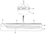
도 1은, 본 발명에 따른 휴대용 단말기의 외관을 개략적으로 도시한 도면이다. 도 2는, 플레이트가 탈부착되는 모습을 도시한 도면이다. 도 3은, 본 발명에 적용되는 플레이트의 다양한 실시예들을 도시한 도면이다. 도 4는, 본 발명에 적용되는 반투명 필름의 예를 도시한 도면이다. 도 5는, 본 발명에 따른 휴대용 단말기의 개략적인 블록 구성도이다. 도 1 내지 도 5를 참조하여, 본 발명에 따른 휴대용 단말기의 일 실시예를 상세히 설명하면 다음과 같다.1 is a view schematically showing the appearance of a portable terminal according to the present invention. 2 is a diagram illustrating a state in which a plate is attached and detached. 3 is a diagram illustrating various embodiments of a plate applied to the present invention. 4 is a diagram illustrating an example of a translucent film applied to the present invention. 5 is a schematic block diagram of a portable terminal according to the present invention. 1 to 5, an embodiment of a portable terminal according to the present invention will be described in detail as follows.
본 발명에 따른 휴대용 단말기는, 적어도 하나의 몸체로 이루어질 수 있다. 예를 들어, 폴더(folder) 타입, 슬라이드(slide) 타입, 바(bar) 타입, 스윙(swing) 타입 등 여러 가지 형상의 휴대용 단말기에 본 발명이 적용될 수 있다. 이하, 도 1에 도시된 폴더형 휴대용 단말기를 실시예로서 설명하기로 한다.The portable terminal according to the present invention may be formed of at least one body. For example, the present invention can be applied to a portable terminal having various shapes such as a folder type, a slide type, a bar type, and a swing type. Hereinafter, the foldable portable terminal shown in FIG. 1 will be described as an embodiment.
도 1에 도시된 휴대용 단말기는, 제1 몸체(10), 제2 몸체(20), 제1 표시부(12), 제2 표시부(14), 플레이트(16) 및 결합부(18)를 포함하여 구성된다.The portable terminal illustrated in FIG. 1 includes a
제1 표시부(12) 및 제2 표시부(14)는, 상기 휴대용 단말기의 상태 혹은 각종 정보를 디스플레이하기 위한 장치이다. 제1 표시부(12)와 제2 표시부(14)는 EL(Electro-Luminescence) 디스플레이 패널과 LCD(Liquid Crystal Display) 패널 중 어느 하나로 구현될 수 있다. 도 1에 도시된 바와 같이, 제1 표시부(12)는 제1 몸체(10)에 설치되고, 상기 제2 표시부(14)는 제2 몸체(20)의 외면에 설치된다. 결합부(18)는, 제1 몸체(10)와 제2 몸체(20)를 결합하는 수단이다.The
플레이트(16)는, 제2 표시부(14)의 면(面) 발광을 복수의 점(點) 발광으로 전환하는 발광 전환 수단이다. 면 발광을 점 발광으로 전환하게 되면, 제2 표시부(14)에 디스플레이되는 정보의 일부는 가려지고 나머지 일부만이 외부로 노출되는 효과가 발생한다. 플레이트(16)는, 다수의 구멍(22)이 형성되고, 제2 표시부(14) 위에 탈부착될 수 있도록 설치된다. 플레이트(16)에 형성된 상기 다수의 구멍(22)에 의해, 제2 표시부(14)에 디스플레이되는 정보의 일부는 가려지고 나머지 일부만이 외부로 노출된다.The
플레이트(16)가 제2 표시부(14) 위에 탈부착될 수 있도록 설치되기 위해서는, 플레이트(16)를 고정시키는 고정 수단이 필요하다. 상기 고정 수단은 다양한 형태로 구현될 수 있다. 도 2는, 슬라이드 방식의 고정 수단을 도시하고 있다. 즉, 도 2에 도시된 바와 같이, 제2 몸체(20)는, 그 외면의 일부에 플레이트(16)를 고정하기 위한 홈을 갖는 돌출부가 형성된다. 플레이트(16)는, 상기 홈을 따라 끼워지거나 빠짐으로써, 제2 몸체(20) 및 제2 표시부(14) 위에 탈부착될 수 있다.In order for the
그리고, 플레이트(16)는, 도 3(a) 내지 (c)에 도시된 바와 같이, 매트릭스(matrix) 형태로 배열된, 다양한 형상의 구멍(22)이 형성될 수 있다. 또한, 플레이트(16)는, 스틸(steel), 아크릴, 에나멜 필름 등 다양한 소재로 구현될 수 있다.In addition, the
플레이트(16)외에도 다양한 형태의, 면 발광을 점 발광으로 전환하는 발광 전환 수단이 본 발명에 적용될 수 있다. 도 4에 도시된 반투명 필름(30)이 그 대표 적인 예이다. 반투명 필름(30)은, PET(polyethylen terephthalate) 필름(301), PVC(polyvinyl chloride) 필름(303), 광 확산 PVA(polyvinyl acetate) 코팅막(305) 및 차단 코팅막(307)으로 구성될 수 있다. 반투명 필름(30)은, 40 ~ 70%의 불투명도와, 80 ~ 100%의 백색도와, 30 ~ 60%의 총광선 반사율과, 30 ~ 70%의 총광선 평균 투과율을 가지는 것이 바람직하다. 차단 코팅막(307)이 면 발광을 점 발광으로 전환하는 역할을 하게 된다. 즉, 차단 코팅막(307)이 존재하는 부분은 제2 표시부(14)로부터 발생하는 광을 반투명하게 투과시키고, 차단 코팅막(307)이 존재하지 않는 부분은 제2 표시부(14)로부터 발생하는 광을 그대로 투과시킨다. 따라서, 차단 코팅막(307)이 존재하지 않는 부분이 플레이트(16)에 형성된 구멍(22)에 해당한다. 단, 도 4에 도시된 반투명 필름(30)은, 제2 표시부(14)에 실제 장착되는 반투명 필름의 일부를 도시하고 있다. 즉, 실제 장착되는 반투명 필름은, 차단 코팅막(307)이 존재하지 않는 부분을 다수 구비하게 된다.In addition to the
도 5를 참조하여, 도 1 및 도 2에 도시된, 플레이트(16) 혹은 반투명 필름(30)과 같은 발광 전환 수단을 구비한 휴대용 단말기에서, 본 발명에 따라 소정의 정보를 디스플레이하는 동작을 상세히 설명하면 다음과 같다.With reference to FIG. 5, in the portable terminal with light emission switching means such as the
도 5에 도시된, 본 발명에 따른 휴대용 단말기는, 무선 통신부(40), 프로세서(42), 입력부(44), 메모리부(46), 제1 표시부(12) 및 제2 표시부(14)를 포함하여 구성된다.5, the portable terminal according to the present invention includes a
무선 통신부(40)는, 이동통신망과 데이터를 송수신하기 위한 무선 통신 수단이다. 입력부(44)는, 사용자로부터 각종 정보나 명령을 입력받기 위한 입력 장치로 서, 키 패드 혹은 터치 스크린 등으로 구현될 수 있다. 메모리부(46)는, 본 발명에 따른 휴대용 단말기의 전반적인 동작을 제어하는 소정의 프로그램을 저장하고 있으며, 프로세서(42)에 의해 휴대용 단말기의 전반적인 동작이 수행될 때 입출력되는 데이터 및 처리되는 각종 데이터를 저장한다. 프로세서(42)는, 본 발명에 따른 휴대용 단말기의 전반적인 동작을 총괄한다. 무선 통신부(40), 프로세서(42), 입력부(44) 및 메모리부(46)는, 각각 제1 몸체(10) 및 제2 몸체(20) 중 어느 하나에 설치될 수 있다.The
프로세서(42)는, 소정의 정보가 제2 표시부(14)에 디스플레이되도록 제어하는 경우, 그 디스플레이 방식을 다양하게 제어함으로써, 플레이트(16) 혹은 반투명 필름(30)과 같은 발광 전환 수단의 효과를 극대화할 수 있다. 그 예를 들면 다음과 같다.When the
첫째, 프로세서(42)는, 상기 정보가 제2 표시부(14)에서 어느 하나의 방향으로 스크롤되면서 디스플레이되도록 제어한다. 예를 들어, "AM: 09: 45: 30"와 같은 현재 시각에 관한 정보가, 왼쪽에서 오른쪽으로 흘러가도록 디스플레이될 수 있다.First, the
둘째, 프로세서(42)는, 제2 표시부(14)에서, 소정의 주기마다 상기 정보의 디스플레이 유무를 반복하도록 제어한다. 예를 들어, "AM: 09: 45: 30"와 같은 현재 시각에 관한 정보가, 깜빡거리도록 디스플레이될 수 있다.Secondly, the
셋째, 프로세서(42)는, 제2 표시부(14)에서, 소정의 주기마다, 상기 정보가 점차 희미해져 사라지고 다시 점차 뚜렷해지는 것을 반복하도록 제어한다. 예를 들어, "AM: 09: 45: 30"와 같은 현재 시각에 관한 정보가, 점점 희미해지면서 사라졌 다가, 다시 희미해진 상태로 표시되어 점점 뚜렷해지는 동작이 반복될 수 있다.Third, the
상기와 같은 정보의 디스플레이 방식 제어에 의하면, 제2 표시부(14)를 통해 디스플레이되는 정보가 상기 발광 전환 수단에 의해 그 일부가 가려지고 나머지 일부만이 디스플레이됨으로써, 아날로그(analog) 방식의 디스플레이처럼 보여지는 효과가 극대화될 수 있다. 도 6은, 본 발명에 따라 플레이트(16)를 통해 정보가 보여지는 예를 도시한 도면이다. 도 6(a)는 외부로부터 호(call)를 수신한 경우이고, 도 6(b)는 외부로부터 문자 메시지를 수신한 경우이다. 도 6(c)는 MP3 음악 파일이 구동되는 경우이다.According to the display method control of the information as described above, the information displayed through the
이상에서 설명한 본 발명은, 본 발명이 속하는 기술분야에서 통상의 지식을 가진 자에 있어 본 발명의 기술적 사상을 벗어나지 않는 범위 내에서 여러 가지 치환, 변형 및 변경이 가능하므로 전술한 실시예 및 첨부된 도면에 의해 한정되는 것이 아니다.The present invention described above is capable of various substitutions, modifications, and changes without departing from the spirit of the present invention for those skilled in the art to which the present invention pertains. It is not limited by the drawings.
상기에서 설명한 본 발명에 따른 휴대용 단말기의 효과를 설명하면 다음과 같다.The effects of the portable terminal according to the present invention described above are as follows.
첫째, 본 발명에 의하면, 휴대용 단말기의 표시부에, 다수의 구멍이 형성된 플레이트 혹은 반투명 필름과 같은 발광 전환 수단을 탈부착함으로써, 사용자에게 디지털 방식의 정보 표시뿐만 아니라 아날로그 방식의 느낌을 주는 정보 표시를 제공할 수 있는 효과가 있다.First, according to the present invention, by attaching and detaching a light-emitting switching means such as a plate or a translucent film having a plurality of holes formed on the display portion of the portable terminal, it provides not only a digital information display but also an information display giving an analog feel. It can work.
둘째, 본 발명에 의하면, 휴대용 단말기의 표시부에, 플레이트 혹은 반투명 필름과 같은 발광 전환 수단을 장착함으로써, 표시부에 각종 이물질의 점착이나 스크래치 등을 방지하여 표시부를 외부 노출로부터 보호할 수 있는 효과가 있다.Secondly, according to the present invention, by attaching a light emitting switching means such as a plate or a translucent film to the display unit of the portable terminal, the display unit can be prevented from being exposed to external exposure by preventing adhesion or scratches of various foreign substances. .
Claims (13)
Priority Applications (4)
| Application Number | Priority Date | Filing Date | Title |
|---|---|---|---|
| KR1020060045627A KR20070112567A (en) | 2006-05-22 | 2006-05-22 | Handheld terminal |
| US11/751,486 US8350874B2 (en) | 2006-05-22 | 2007-05-21 | Mobile terminal and method of controlling a display device |
| EP07010056.5A EP1860488B1 (en) | 2006-05-22 | 2007-05-21 | Mobile display device with selectable means for modifying an image |
| CNA2007101040805A CN101080067A (en) | 2006-05-22 | 2007-05-22 | Mobile terminal and method for controlling display device |
Applications Claiming Priority (1)
| Application Number | Priority Date | Filing Date | Title |
|---|---|---|---|
| KR1020060045627A KR20070112567A (en) | 2006-05-22 | 2006-05-22 | Handheld terminal |
Publications (1)
| Publication Number | Publication Date |
|---|---|
| KR20070112567A true KR20070112567A (en) | 2007-11-27 |
Family
ID=38477340
Family Applications (1)
| Application Number | Title | Priority Date | Filing Date |
|---|---|---|---|
| KR1020060045627A Ceased KR20070112567A (en) | 2006-05-22 | 2006-05-22 | Handheld terminal |
Country Status (4)
| Country | Link |
|---|---|
| US (1) | US8350874B2 (en) |
| EP (1) | EP1860488B1 (en) |
| KR (1) | KR20070112567A (en) |
| CN (1) | CN101080067A (en) |
Families Citing this family (15)
| Publication number | Priority date | Publication date | Assignee | Title |
|---|---|---|---|---|
| US8612888B2 (en) | 2008-04-01 | 2013-12-17 | Litl, Llc | Method and apparatus for managing digital media content |
| US9003315B2 (en) | 2008-04-01 | 2015-04-07 | Litl Llc | System and method for streamlining user interaction with electronic content |
| US8289688B2 (en) | 2008-04-01 | 2012-10-16 | Litl, Llc | Portable computer with multiple display configurations |
| CN101749562B (en) * | 2008-12-05 | 2011-08-17 | 上海向隆电子科技有限公司 | Structure for eliminating bright lines of splice type backlight module |
| KR101771454B1 (en) * | 2010-09-03 | 2017-08-25 | 엘지전자 주식회사 | Mobile terminal and method of fabricating case thereof |
| KR101425443B1 (en) * | 2012-05-09 | 2014-08-04 | 엘지전자 주식회사 | Pouch and mobile device having the same |
| KR20150043806A (en) * | 2013-10-15 | 2015-04-23 | 엘지전자 주식회사 | Terminal and operating method thereof |
| US9651985B2 (en) | 2013-12-03 | 2017-05-16 | Htc Corporation | Accessory, electronic assembly and controlling method |
| EP2881834B1 (en) * | 2013-12-03 | 2017-08-16 | HTC Corporation | Accessory and method for forming an accessory. |
| US9375874B2 (en) | 2013-12-03 | 2016-06-28 | Htc Corporation | Accessory, electronic assembly, control method, and method for forming an accessory |
| USD785613S1 (en) | 2014-01-29 | 2017-05-02 | Htc Corporation | Case for a portable electronic device |
| TWI595410B (en) * | 2014-03-24 | 2017-08-11 | 宏達國際電子股份有限公司 | Method of controlling a mobile electronic device through a cover, mobile electronic device using the same and storage |
| US20160291370A1 (en) * | 2015-04-01 | 2016-10-06 | Google Inc. | Partitioned display and control to provide power management in liquid crystal display |
| KR102613168B1 (en) * | 2017-01-04 | 2023-12-14 | 삼성전자 주식회사 | Cover accessory and electronic device using the same |
| US11003048B1 (en) | 2019-12-13 | 2021-05-11 | VG Technology Inc. | Polarized imaging apparatus for use with a mobile device |
Family Cites Families (17)
| Publication number | Priority date | Publication date | Assignee | Title |
|---|---|---|---|---|
| JP3085471B2 (en) * | 1991-01-24 | 2000-09-11 | ソニー株式会社 | Remote commander |
| JP3263250B2 (en) | 1994-08-24 | 2002-03-04 | 株式会社東芝 | Liquid crystal display |
| KR0163895B1 (en) | 1995-01-06 | 1999-01-15 | 김광호 | LCD with improved viewing angle |
| JP3606498B2 (en) * | 1996-04-26 | 2005-01-05 | 三菱電機株式会社 | Portable information terminal device |
| US6046849A (en) * | 1996-09-12 | 2000-04-04 | Sharp Kabushiki Kaisha | Parallax barrier, display, passive polarisation modulating optical element and method of making such an element |
| US5870110A (en) * | 1997-04-28 | 1999-02-09 | Mallory; Perry M. | Hand held messaging system |
| KR100593996B1 (en) | 1998-12-17 | 2006-09-27 | 삼성전자주식회사 | How to display wallpaper on a mobile phone |
| US7016869B1 (en) | 2000-04-28 | 2006-03-21 | Shutterfly, Inc. | System and method of changing attributes of an image-based product |
| US20030016316A1 (en) | 2001-06-20 | 2003-01-23 | 3M Innovative Properties Company | Interchangable polarizers for electronic devices having a liquid crystal display |
| EP1324297A2 (en) * | 2001-12-13 | 2003-07-02 | Matsushita Electric Industrial Co., Ltd. | Displaying method, displaying apparatus, filtering unit, filtering process method, recording medium for storing filtering process programs, and method for processing image |
| GB0202782D0 (en) | 2002-02-06 | 2002-03-27 | Screen Technology Ltd | Display |
| JP4172968B2 (en) | 2002-08-19 | 2008-10-29 | ソニー株式会社 | Mobile terminal device |
| TWI258329B (en) * | 2002-12-04 | 2006-07-11 | Fih Co Ltd | Method of manufacturing multihole cover |
| ATE542366T1 (en) * | 2002-12-10 | 2012-02-15 | Sony Ericsson Mobile Comm Ab | EFFECTS GENERATION FOR IMAGES |
| JP2004317585A (en) * | 2003-04-11 | 2004-11-11 | Mitsubishi Electric Corp | Monitor with lid |
| JP4095530B2 (en) * | 2003-10-01 | 2008-06-04 | キヤノン株式会社 | Image processing apparatus and method |
| JP2005221897A (en) | 2004-02-06 | 2005-08-18 | Fujitsu Hitachi Plasma Display Ltd | Display panel apparatus |
-
2006
- 2006-05-22 KR KR1020060045627A patent/KR20070112567A/en not_active Ceased
-
2007
- 2007-05-21 US US11/751,486 patent/US8350874B2/en not_active Expired - Fee Related
- 2007-05-21 EP EP07010056.5A patent/EP1860488B1/en not_active Not-in-force
- 2007-05-22 CN CNA2007101040805A patent/CN101080067A/en active Pending
Also Published As
| Publication number | Publication date |
|---|---|
| EP1860488A2 (en) | 2007-11-28 |
| US20070268202A1 (en) | 2007-11-22 |
| EP1860488B1 (en) | 2016-06-29 |
| EP1860488A3 (en) | 2008-11-05 |
| US8350874B2 (en) | 2013-01-08 |
| CN101080067A (en) | 2007-11-28 |
Similar Documents
| Publication | Publication Date | Title |
|---|---|---|
| KR20070112567A (en) | Handheld terminal | |
| US8996038B2 (en) | Method for providing idle screen layer endowed with visual effect and method for providing idle screen by using the same | |
| EP2282491B1 (en) | Terminal, in particular mobile terminal having an LED backlight unit | |
| CN103621051B (en) | Electronic device with color changing layer on light template layer | |
| JP4462817B2 (en) | Visualization method of character input mode by key backlight multicolor lighting | |
| TW200701116A (en) | Method for zooming image on touch screen | |
| US20080280652A1 (en) | Reconfigurable keypad method in handset device operable with plural subsystems | |
| US20080192019A1 (en) | Method of controlling touch pad in mobile communication terminal and mobile communication terminal thereof | |
| US20110059774A1 (en) | Wireless Communication Device for Providing a Visual Representation of a Widget | |
| TW200627366A (en) | Method and system for quick screen switching in a multi-monitor environment | |
| US8369890B2 (en) | Mobile electronic device with an illuminated static display | |
| JP5178045B2 (en) | Mobile terminal device | |
| JP5777454B2 (en) | Lighting control system, lighting control device, and lighting control method | |
| TW200513941A (en) | Image display system, image display device and image display method | |
| US20110175817A1 (en) | Mobile terminal | |
| KR100653784B1 (en) | Mobile communication terminal with multiple outputs | |
| KR20040029857A (en) | Picture display method of mobile communication terminal | |
| WO2007117725A2 (en) | A user interface device of a wireless communication device utilizing fluorescent illumination | |
| JP2009130717A (en) | Panel switch device | |
| KR101133801B1 (en) | Method of practicing multimedia function using jog dial key in mobile terminal and the mobile terminal therefor | |
| JP5684357B2 (en) | Mobile device | |
| JP5341661B2 (en) | Portable electronic devices | |
| JP2007172199A (en) | Key touch confirmation device and portable information device | |
| JP2006065022A (en) | Portable information terminal | |
| TW200601136A (en) | A method for selecting icon and a device for displaying an on screen display |
Legal Events
| Date | Code | Title | Description |
|---|---|---|---|
| PA0109 | Patent application |
Patent event code: PA01091R01D Comment text: Patent Application Patent event date: 20060522 |
|
| PG1501 | Laying open of application | ||
| A201 | Request for examination | ||
| PA0201 | Request for examination |
Patent event code: PA02012R01D Patent event date: 20100216 Comment text: Request for Examination of Application Patent event code: PA02011R01I Patent event date: 20060522 Comment text: Patent Application |
|
| E902 | Notification of reason for refusal | ||
| PE0902 | Notice of grounds for rejection |
Comment text: Notification of reason for refusal Patent event date: 20110627 Patent event code: PE09021S01D |
|
| E601 | Decision to refuse application | ||
| PE0601 | Decision on rejection of patent |
Patent event date: 20120224 Comment text: Decision to Refuse Application Patent event code: PE06012S01D Patent event date: 20110627 Comment text: Notification of reason for refusal Patent event code: PE06011S01I |