KR20070099455A - Image forming apparatus - Google Patents
Image forming apparatus Download PDFInfo
- Publication number
- KR20070099455A KR20070099455A KR1020070032306A KR20070032306A KR20070099455A KR 20070099455 A KR20070099455 A KR 20070099455A KR 1020070032306 A KR1020070032306 A KR 1020070032306A KR 20070032306 A KR20070032306 A KR 20070032306A KR 20070099455 A KR20070099455 A KR 20070099455A
- Authority
- KR
- South Korea
- Prior art keywords
- sheet
- suction
- sensor
- air
- tray
- Prior art date
- Legal status (The legal status is an assumption and is not a legal conclusion. Google has not performed a legal analysis and makes no representation as to the accuracy of the status listed.)
- Granted
Links
Images


Classifications
-
- B—PERFORMING OPERATIONS; TRANSPORTING
- B65—CONVEYING; PACKING; STORING; HANDLING THIN OR FILAMENTARY MATERIAL
- B65H—HANDLING THIN OR FILAMENTARY MATERIAL, e.g. SHEETS, WEBS, CABLES
- B65H3/00—Separating articles from piles
- B65H3/08—Separating articles from piles using pneumatic force
- B65H3/12—Suction bands, belts, or tables moving relatively to the pile
- B65H3/124—Suction bands or belts
- B65H3/128—Suction bands or belts separating from the top of pile
-
- G—PHYSICS
- G03—PHOTOGRAPHY; CINEMATOGRAPHY; ANALOGOUS TECHNIQUES USING WAVES OTHER THAN OPTICAL WAVES; ELECTROGRAPHY; HOLOGRAPHY
- G03G—ELECTROGRAPHY; ELECTROPHOTOGRAPHY; MAGNETOGRAPHY
- G03G15/00—Apparatus for electrographic processes using a charge pattern
-
- B—PERFORMING OPERATIONS; TRANSPORTING
- B65—CONVEYING; PACKING; STORING; HANDLING THIN OR FILAMENTARY MATERIAL
- B65H—HANDLING THIN OR FILAMENTARY MATERIAL, e.g. SHEETS, WEBS, CABLES
- B65H1/00—Supports or magazines for piles from which articles are to be separated
- B65H1/08—Supports or magazines for piles from which articles are to be separated with means for advancing the articles to present the articles to the separating device
- B65H1/14—Supports or magazines for piles from which articles are to be separated with means for advancing the articles to present the articles to the separating device comprising positively-acting mechanical devices
-
- B—PERFORMING OPERATIONS; TRANSPORTING
- B65—CONVEYING; PACKING; STORING; HANDLING THIN OR FILAMENTARY MATERIAL
- B65H—HANDLING THIN OR FILAMENTARY MATERIAL, e.g. SHEETS, WEBS, CABLES
- B65H3/00—Separating articles from piles
- B65H3/46—Supplementary devices or measures to assist separation or prevent double feed
- B65H3/48—Air blast acting on edges of, or under, articles
-
- B—PERFORMING OPERATIONS; TRANSPORTING
- B65—CONVEYING; PACKING; STORING; HANDLING THIN OR FILAMENTARY MATERIAL
- B65H—HANDLING THIN OR FILAMENTARY MATERIAL, e.g. SHEETS, WEBS, CABLES
- B65H7/00—Controlling article feeding, separating, pile-advancing, or associated apparatus, to take account of incorrect feeding, absence of articles, or presence of faulty articles
- B65H7/02—Controlling article feeding, separating, pile-advancing, or associated apparatus, to take account of incorrect feeding, absence of articles, or presence of faulty articles by feelers or detectors
-
- G—PHYSICS
- G03—PHOTOGRAPHY; CINEMATOGRAPHY; ANALOGOUS TECHNIQUES USING WAVES OTHER THAN OPTICAL WAVES; ELECTROGRAPHY; HOLOGRAPHY
- G03G—ELECTROGRAPHY; ELECTROPHOTOGRAPHY; MAGNETOGRAPHY
- G03G15/00—Apparatus for electrographic processes using a charge pattern
- G03G15/65—Apparatus which relate to the handling of copy material
- G03G15/6502—Supplying of sheet copy material; Cassettes therefor
- G03G15/6511—Feeding devices for picking up or separation of copy sheets
-
- B—PERFORMING OPERATIONS; TRANSPORTING
- B65—CONVEYING; PACKING; STORING; HANDLING THIN OR FILAMENTARY MATERIAL
- B65H—HANDLING THIN OR FILAMENTARY MATERIAL, e.g. SHEETS, WEBS, CABLES
- B65H2406/00—Means using fluid
- B65H2406/30—Suction means
- B65H2406/36—Means for producing, distributing or controlling suction
- B65H2406/366—Means for producing, distributing or controlling suction producing vacuum
- B65H2406/3662—Fans
-
- B—PERFORMING OPERATIONS; TRANSPORTING
- B65—CONVEYING; PACKING; STORING; HANDLING THIN OR FILAMENTARY MATERIAL
- B65H—HANDLING THIN OR FILAMENTARY MATERIAL, e.g. SHEETS, WEBS, CABLES
- B65H2511/00—Dimensions; Position; Numbers; Identification; Occurrences
- B65H2511/10—Size; Dimensions
- B65H2511/15—Height, e.g. of stack
-
- B—PERFORMING OPERATIONS; TRANSPORTING
- B65—CONVEYING; PACKING; STORING; HANDLING THIN OR FILAMENTARY MATERIAL
- B65H—HANDLING THIN OR FILAMENTARY MATERIAL, e.g. SHEETS, WEBS, CABLES
- B65H2511/00—Dimensions; Position; Numbers; Identification; Occurrences
- B65H2511/20—Location in space
-
- B—PERFORMING OPERATIONS; TRANSPORTING
- B65—CONVEYING; PACKING; STORING; HANDLING THIN OR FILAMENTARY MATERIAL
- B65H—HANDLING THIN OR FILAMENTARY MATERIAL, e.g. SHEETS, WEBS, CABLES
- B65H2553/00—Sensing or detecting means
- B65H2553/60—Details of intermediate means between the sensing means and the element to be sensed
- B65H2553/61—Mechanical means, e.g. contact arms
-
- B—PERFORMING OPERATIONS; TRANSPORTING
- B65—CONVEYING; PACKING; STORING; HANDLING THIN OR FILAMENTARY MATERIAL
- B65H—HANDLING THIN OR FILAMENTARY MATERIAL, e.g. SHEETS, WEBS, CABLES
- B65H2801/00—Application field
- B65H2801/03—Image reproduction devices
- B65H2801/06—Office-type machines, e.g. photocopiers
-
- G—PHYSICS
- G03—PHOTOGRAPHY; CINEMATOGRAPHY; ANALOGOUS TECHNIQUES USING WAVES OTHER THAN OPTICAL WAVES; ELECTROGRAPHY; HOLOGRAPHY
- G03G—ELECTROGRAPHY; ELECTROPHOTOGRAPHY; MAGNETOGRAPHY
- G03G2215/00—Apparatus for electrophotographic processes
- G03G2215/00362—Apparatus for electrophotographic processes relating to the copy medium handling
- G03G2215/00367—The feeding path segment where particular handling of the copy medium occurs, segments being adjacent and non-overlapping. Each segment is identified by the most downstream point in the segment, so that for instance the segment labelled "Fixing device" is referring to the path between the "Transfer device" and the "Fixing device"
- G03G2215/004—Separation device
-
- G—PHYSICS
- G03—PHOTOGRAPHY; CINEMATOGRAPHY; ANALOGOUS TECHNIQUES USING WAVES OTHER THAN OPTICAL WAVES; ELECTROGRAPHY; HOLOGRAPHY
- G03G—ELECTROGRAPHY; ELECTROPHOTOGRAPHY; MAGNETOGRAPHY
- G03G2215/00—Apparatus for electrophotographic processes
- G03G2215/00362—Apparatus for electrophotographic processes relating to the copy medium handling
- G03G2215/00535—Stable handling of copy medium
- G03G2215/00717—Detection of physical properties
- G03G2215/00725—Detection of physical properties of sheet presence in input tray
Landscapes
- Engineering & Computer Science (AREA)
- Mechanical Engineering (AREA)
- Physics & Mathematics (AREA)
- General Physics & Mathematics (AREA)
- Sheets, Magazines, And Separation Thereof (AREA)
Abstract
트레이 상에 적재된 시트의 상면을 검지하는 시트면 검지 기구가 제공된다. 시트면 검지 기구는, 반송부로부터 이격된 위치에 배치된 센서와, 센서를 ON/OFF하는 피봇식 센서 플래그와, 트레이 상에 적재된 시트와 평행하게 배치되어, 센서 플래그를 시트의 상면과 접촉하여 피봇시키면서 수직 방향으로 이동하여 센서 플래그에 의해 센서를 ON/OFF하는 시트면 검지 부재를 포함한다.A sheet surface detection mechanism for detecting an upper surface of a sheet stacked on a tray is provided. The sheet surface detection mechanism is arranged in parallel with a sensor disposed at a position spaced apart from the conveying unit, a pivot sensor flag for turning the sensor on and off, and a sheet stacked on a tray, and the sensor flag contacts the upper surface of the sheet. And a sheet surface detecting member which moves in a vertical direction while pivoting and turns the sensor ON / OFF by a sensor flag.
Description
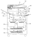
도1은 본 발명의 실시예에 따르는 시트 급송 장치가 마련된 화상 형성 장치의 일예인 프린터의 개략적인 구조를 나타낸 도면.BRIEF DESCRIPTION OF THE DRAWINGS Fig. 1 shows a schematic structure of a printer which is an example of an image forming apparatus provided with a sheet feeding apparatus according to an embodiment of the present invention.
도2는 전술한 시트 급송 장치의 구조를 도시한 도면.Fig. 2 is a diagram showing the structure of the sheet feeding apparatus described above.
도3은 전술한 시트 급송 장치의 시트 급송 동작을 나타낸 제1 도면.3 is a first diagram showing a sheet feeding operation of the sheet feeding apparatus described above.
도4는 전술한 시트 급송 장치의 시트 급송 동작을 나타낸 제2 도면.4 is a second diagram showing a sheet feeding operation of the sheet feeding apparatus described above.
도5는 전술한 시트 급송 장치의 시트 급송 동작을 나타낸 제3 도면.Fig. 5 is a third diagram showing the sheet feeding operation of the sheet feeding apparatus described above.
도6은 전술한 시트 급송 장치에 제공되는 시트면 검지 기구의 구조를 나타낸 도면.Fig. 6 is a diagram showing the structure of the sheet surface detecting mechanism provided in the sheet feeding apparatus described above.
도7은 전술한 시트면 검지 기구에 마련된 시트면 검지 센서 플래그의 구조를 나타낸 도면.Fig. 7 is a diagram showing the structure of the sheet surface detection sensor flag provided in the above-described sheet surface detection mechanism.
도8은 전술한 시트 급송 장치의 시트면 제어 동작을 나타낸 제1 도면.Fig. 8 is a first diagram showing a sheet surface control operation of the sheet feeding apparatus described above.
도9는 전술한 시트 급송 장치의 시트면 제어 동작을 나타낸 제2 도면.Fig. 9 is a second diagram showing the sheet surface control operation of the sheet feeding apparatus described above.
도10은 전술한 시트 급송 장치의 시트면 제어 동작을 나타낸 제3 도면.Fig. 10 is a third view showing the seat surface control operation of the sheet feeding apparatus described above.
도11a 및 도11b는 전술한 시트면 검지 기구를 흡인 반송 벨트의 대각선 아래에서 본 도면.11A and 11B are views of the above-described sheet surface detection mechanism as viewed from below the diagonal of the suction conveyance belt.
도12는 전술한 시트면 검지 기구 내에 마련된 센서 플래그 기구가 흡인 덕트 내에 수납된 상태를 나타낸 도면.Fig. 12 is a diagram showing a state where the sensor flag mechanism provided in the above-described seat surface detection mechanism is accommodated in the suction duct.
도13은 전술한 시트 급송 장치를 제어하기 위한 블록도.Fig. 13 is a block diagram for controlling the sheet feeding apparatus described above.
도14는 종래 시트 급송 장치의 동작을 나타낸 도면.14 is a view showing the operation of the conventional sheet feeding apparatus.
도15는 종래 시트 급송 장치의 시트면 검지 기구를 나타낸 도면.Fig. 15 is a diagram showing a sheet surface detection mechanism of a conventional sheet feeding apparatus.
도16은 종래 시트 급송 장치 내의 말린 시트 쪽으로 공기가 분사된 상태를 나타낸 도면.Fig. 16 is a view showing a state in which air is injected toward a dried sheet in a conventional sheet feeding apparatus.
< 도면의 주요부분에 대한 부호의 설명 ><Description of Symbols for Major Parts of Drawings>
12: 트레이12: tray
21: 흡인 반송 벨트21: suction conveying belt
30: 공기 분사부30: air jet
49: 시트면 검지 기구49: seat surface detection mechanism
50A: 반송부50A: Carrier
50B: 시트면 검지 기구50B: seat surface detection mechanism
51: 흡인 덕트51: suction duct
52: 시트면 검지 센서 플래그52: sheet detection sensor flag
54: 제1 시트면 센서54: first sheet surface sensor
55: 제2 시트면 센서55: second seat surface sensor
103: 시트 급송 장치103: sheet feeding device
[문헌1] 일본 특허 공개평 제7-196187호[Document 1] Japanese Patent Laid-Open No. 7-196187
[문헌2] 일본 특허 출원 공개 제2003-95467호[Patent 2] Japanese Patent Application Publication No. 2003-95467
본 발명은 시트 급송 장치 및 화상 형성 장치에 관한 것이며, 특히, 시트들에 공기를 분사함으로써 시트들 중 하나가 분리되어 급송되는 장치에 관한 것이다.The present invention relates to a sheet feeding apparatus and an image forming apparatus, and more particularly, to an apparatus in which one of the sheets is separated and fed by spraying air on the sheets.
종래에는, 프린터 및 복사기 등의 화상 형성 장치에, 복수의 시트가 수납되어 있는 시트 수납부로부터 시트를 1매씩 급송하는 시트 급송 장치가 마련되어 있다. 이러한 시트 급송 장치로서는, 시트 수납부 내에 수납된 시트 적재물(sheet stack)의 단부에 공기를 분사하여 수 매의 시트들을 부상시키고(blow up), 1매만이 상방에 배치된 흡인 반송 벨트로 흡인되어 반송되는, 공기 시트 급송 방식의 것이 있다. 예를 들어, 이런 종류의 시트 급송 장치가 일본 특허 공개평 제7-196187호에 개시되어 있다. Conventionally, the sheet feeding apparatus which feeds a sheet one by one from the sheet accommodating part in which several sheets are accommodated is provided in image forming apparatuses, such as a printer and a copier. As such a sheet feeding apparatus, air is blown up to an end portion of a sheet stack stored in a sheet storage portion to blow up several sheets, and only one sheet is sucked by a suction conveyance belt disposed upward. There is an air sheet feeding method that is conveyed. For example, a sheet feeding apparatus of this kind is disclosed in Japanese Patent Laid-Open No. 7-196187.
도14는 공기 시트 급송 방식의 시트 급송 장치를 나타낸 일예이다. 도14에 도시되어 있는 바와 같이, 복수의 시트(S)가 수납되어 있는 시트 수납부인 스토리지(storage)(11) 내에서 승강될 수 있도록 시트(S)들이 적재되어 있는 트레이(12)가 배치된다. 또한, 이 스토리지(11) 위에는, 시트(S)들을 흡인 및 반송하는 반송부(50A)와, 트레이 상의 시트 적재물의 단부에 공기를 분사하여 수 매의 시트(S)들을 부상시킴과 함께 이들 시트들을 서로 분리시키기 위한 공기 분사부(30)가 마련되어 있다.14 is an example showing the sheet feeding apparatus of the air sheet feeding system. As shown in Fig. 14, a
여기에서, 반송부(50A)에는, 벨트 구동 롤러(41) 위로 통과하며 시트(S)들을 흡인하여 이들을 도14의 오른쪽으로 반송하는 흡인 반송 벨트(21)와, 시트(S)를 흡인 반송 벨트(21)로 흡인되도록 하기 위해 부압을 발생시키는 흡인 팬(36)이 마련되어 있다. 또한, 흡인 반송 벨트(21) 내에 배치되며 흡인 벨트(21) 내에 형성된 흡인 구멍을 통해 공기를 흡인하도록 작용하는 흡인 덕트(51)가 제공된다. 게다가, 흡인 팬(36)에 의한 흡인 동작을 ON/OFF하기 위해, 흡인 셔터(37)가 흡인 팬(36)과 흡인 덕트(51) 사이에 배치된다.Here, the
또한, 공기 분사부(30)에는, 수납된 시트 적재물의 상부에 공기를 분사하기 위한 밀착완화 노즐(loosening nozzle)(33) 및 분리 노즐(34)과, 분리 팬(31), 그리고 분리 팬(31)으로부터 각 노즐(33, 34)로 공기를 공급하는 분리 덕트(32)가 제공된다.In addition, the
또한, 분리 팬(31)에 의해 화살표 C로 나타낸 방향으로 흡인된 공기의 일부가 밀착완화 노즐(33)에 의해 분리 덕트(32)를 통해 화살표 D로 나타낸 방향으로 분사되어, 트레이(12) 상에 지지된 시트 적재물 중 수 매의 상부 시트들을 부상시킨다. 또한, 다른 공기가 분리 노즐(34)에 의해 화살표 E로 나타낸 방향으로 분사되어, 밀착완화 노즐(33)에 의해 부상된 수 매의 시트들 중 최상위 시트만을 분리하여 흡인 반송 벨트(21)에 흡인되도록 작용한다.In addition, a part of the air sucked by the
첨언하면, 이와 같이 흡인 반송 벨트(21)에 시트(S)를 흡인시키기 위해서는, 스토리지(11) 내에 수납되어 있는 시트 적재물 중 최상위 시트(Sa)가 흡인 벨트(21)에 흡인될 수 있는 미리 정해진 시트 급송 위치로 유지되어야 할 필요가 있다.Incidentally, in order to suck the sheet S in the
따라서, 최상위 시트(Sa)의 위치를 검지하도록 작용하는 센서 플래그와 시트면 검지 센서로 형성된 시트면 검지 기구가 마련되었다. 이러한 시트면 검지 기구에서는, 시트들을 지지하는 트레이(12)의 승강이 시트면 검지 센서에 의한 센서 플래그의 변위를 검지함으로써 제어되었다. 또한, 종래에는, 이러한 시트면 검지 기구의 시트면 검지 센서 및 센서 플래그가 흡인 덕트(51)의 내부 안쪽에 배치되었다. 예를 들어, 이러한 구조의 일예가 일본 특허 출원 공개 제2003-95467호에 개시되어 있다.Therefore, the sheet surface detection mechanism provided with the sensor flag and the sheet surface detection sensor which act to detect the position of the top sheet Sa was provided. In such a sheet surface detection mechanism, the lifting and lowering of the
그러나, 이와 같이 시트면 검지 센서 등이 흡인 덕트(51) 내에 배치될 경우, 흡인 덕트(51) 내에 시트면 검지 센서 등을 수용할 공간이 있어야만 한다. 더욱이, 이러한 수용 공간이 형성되는 경우, 흡인 덕트(51)가 커지고, 이에 따라 화상 형성 장치 전체가 대형화된다.However, when the sheet surface detection sensor or the like is disposed in the
또한, 흡인 덕트(51)의 용적도 커진다. 여기에서, 흡인 덕트(51)의 용적은 흡인 팬(36)의 능력(power)과 밀접한 관계를 갖기 때문에, 흡인 덕트(51)의 큰 용적은 흡인 팬(36)을 대형화시키며, 이에 따라 에너지 소비의 낭비 또는 높은 비용을 초래한다. 게다가, 흡인 덕트(51)가 높은 기밀성(air-tightness)을 갖도록 요구되더라도, 시트면 검지 기구가 순조롭게 작동함과 동시에, 기밀성을 유지하면서 시트면 검지 기구의 센서 등의 전기 부품을 배치하는 것은 매우 곤란하다.In addition, the volume of the
이러한 이유로, 장치의 소형화를 달성하거나 안정적인 성능을 유지하기 위해서는, 예를 들어 도15에 도시된 바와 같이, 시트면 검지 기구(50B)가 흡인 덕트(51) 외부에 배치되는 것이 실용적이다. 이제, 이와 같이 흡인 덕트(51) 외부에 배치되어 트레이(12)에 적재된 시트(S)들의 상면을 검지하는 기능을 하는 시트면 검지 기구(50B)에 대해 기술된다.For this reason, in order to achieve miniaturization of the apparatus or to maintain stable performance, it is practical to arrange the sheet
이 시트면 검지 기구(50B)에는, 지지 샤프트(53) 둘레에 피봇식으로 지지된 시트면 검지 센서 플래그(52)와, 시트면 검지 센서 플래그(52)를 ON/OFF하도록 된 제1 시트면 센서(54)와 제2 시트면 센서(55)가 마련되어 있다.The sheet
여기서, 시트면 검지 센서 플래그(52)에는, 최상위 시트(Sa)의 상면과 접촉하는 접촉부(52A)와, 제1 시트면 센서(54)의 수광부를 차광하는 제1 검지부(52B)와, 제2 시트면 센서(55)의 수광부를 차광하는 제2 검지부(52C)가 마련되어 있다.Here, the sheet surface
이러한 구조의 시트면 검지 기구(50B)에서는, 트레이(12)가 시트(S)들을 급송하기 위해 올려질 때, 시트면 검지 센서 플래그(52)의 접촉부(52A)가 최상위 시트(Sa)의 상면과 접촉하고, 그 후, 트레이(12)의 상승과 함께 시트면 검지 센서 플래그(52)가 피봇된다. 그 다음, 이와 같이 시트면 검지 센서 플래그(52)가 피봇될 때, 제1 검지부(52B)와 제2 검지부(52C)가 각각 제1 시트면 센서(54) 및 제2 시트면 센서(55)를 적절하게 ON/OFF한다.In the sheet
또한, 트레이(12)의 승강을 제어하도록 작용하는 제어기가 이들 제1 및 제2 시트면 센서(54, 55)의 ON/OFF에 따라 트레이(12)를 승강시켜서 최상위 시트(Sa)를 미리 정해진 시트 급송 위치로 유지한다.In addition, a controller which acts to control the lifting of the
그러나, 이러한 시트면 검지 기구를 갖는 종래의 시트 급송 장치 및 화상 형성 장치에서는, 예를 들어, 시트 반송 방향에서의 하류측 시트의 단부가 위쪽으로 말려진(curl) 경우, 공기가 밀착완화 노즐(33)로부터 시트들 쪽으로 분사된 때, 도 16에 도시된 바와 같이 시트들이 부상 상태로 될 것이다. 여기서, 이 상태일 때, 시트면 검지 센서 플래그(52)의 접촉부(52A)가 접촉되는 위치에서의 최상위 시트(Sa)의 시트면 높이가 최적인(예를 들어, SL) 반면, 시트(S)들의 하류측 단부들은 흡인 반송 벨트(21)와 접촉하게 되어 있다.However, in the conventional sheet feeding apparatus and image forming apparatus having such a sheet surface detecting mechanism, for example, when the end of the downstream sheet in the sheet conveying direction is curled upward, air is tightly adhered to the nozzle ( When ejected from 33) towards the sheets, the sheets will be in a floating state as shown in FIG. Here, in this state, the sheet surface height of the top sheet Sa at the position where the
그 다음, 이 상태에서, 최상위 시트(Sa)가 흡인 반송 벨트(21)로 흡인됨과 함께 분리 공기가 분리 노즐로부터 분사될 때, 화살표로 나타낸 분리 공기가 시트의 말림으로 방해되어 시트들 사이로 원활하게 들어갈 수 없게 된다. 따라서, 시트들이 서로 충분히 분리될(밀착완화될) 수 없다.Then, in this state, when the uppermost sheet Sa is sucked by the
이에 따라, 시트 적재물의 다음 시트(Sb) 또는 복수의 후속 시트들이 최상위 시트(Sa)와 함께 잘못 반송되어, 시트의 이중 급송 또는 걸림[시트 걸림(sheet jamming)]이 발생한다는 문제를 야기한다.Accordingly, the next sheet Sb or a plurality of subsequent sheets of the sheet stack are incorrectly conveyed together with the top sheet Sa, causing a problem that double feeding or jamming of the sheet (sheet jamming) occurs.
즉, 장치의 대형화를 방지하는 목적을 위해 시트면 검지 기구(50B)가 흡인 덕트(51)의 외부에 배치된 경우, 예를 들어, 위쪽으로 말려진 시트들이 있는 경우, 흡인 반송 벨트(21)에 대한 시트들의 간격이 정확하게 인식될 수 없다. 결과적으로, 시트들의 이중 급송 또는 걸림 등의 급송 장애(feeding failure)가 발생할 것이다.That is, when the sheet
따라서, 본 발명은 이러한 현상을 감안하여 안출된 것으로서, 대형화시키지 않으면서 신뢰성 있게 시트들을 급송할 수 있는 시트 급송 장치 및 화상 형성 장치를 제공하는 것을 그 목적으로 한다.Accordingly, an object of the present invention is to provide a sheet feeding apparatus and an image forming apparatus that can reliably feed sheets without increasing the size thereof.
본 발명은 화상 형성부에서, 시트 급송 장치로부터 급송된 시트 상에 화상을 형성하는 화상 형성 장치를 제공하며, 시트 급송 장치는, 시트를 지지하는 트레이와, 트레이에 의해 지지된 시트의 단부에 공기를 분사하는 공기 분사부와, 공기 분사부에 의해 분사된 공기에 의해 부상된 시트를 흡인하여 반송하는 반송부와, 부상된 시트의 상면을 검지하는 시트면 검지 기구를 포함하며, 시트면 검지 기구는, 반송부로부터 시트 반송 방향에 있어서의 상류측으로 이격된 위치에 배치된 센서부와, 센서부를 ON/OFF하는 센서 플래그와, 센서 플래그에 접속되며, 센서부가 배치되어 있는 측으로부터 반송부 아래 쪽으로 그리고 시트 반송 방향에 있어서의 하류측 쪽으로 연장하여 부상된 시트와 접촉 가능한 시트면 검지 부재를 포함한다.The present invention provides an image forming apparatus for forming an image on a sheet fed from a sheet feeding apparatus in an image forming unit, the sheet feeding apparatus comprising: a tray for supporting a sheet and air at an end portion of the sheet supported by the tray; And a seat surface detecting mechanism for detecting the upper surface of the injured sheet, and a conveying portion for sucking and conveying the sheet floated by the air injected by the air ejecting portion. Is connected to a sensor unit disposed at a position spaced upstream in the sheet conveying direction from the conveying unit, a sensor flag for turning on / off the sensor unit, and a sensor flag, and is located below the conveying unit from the side where the sensor unit is disposed. And a sheet surface detecting member extending toward the downstream side in the sheet conveying direction and in contact with the floating sheet.
이하, 본 발명을 실행하기 위한 최상의 모드가 도면을 참조하여 상세히 설명될 것이다.Best Mode for Carrying Out the Invention The best mode for carrying out the invention will now be described in detail with reference to the drawings.
도1은 본 발명의 실시예에 따르는 시트 급송 장치가 마련된 화상 형성 장치의 일예인 프린터의 개략적인 구조를 나타낸 도면이다.1 is a view showing a schematic structure of a printer which is an example of an image forming apparatus provided with a sheet feeding apparatus according to an embodiment of the present invention.
도1에서, 프린터(100)의 프린터 본체(101)의 상부에는, 자동 문서 급송 장치(120)의 문서 테이블로서 작용하는 플래튼 글래스(120a) 위에 놓여진 문서(D)의 화상 판독부(130)가 제공되어 있다. 또한, 화상 판독부(130) 아래에는, 화상 형성부(102)와, 이 화상 형성부(102)에 시트(S)들을 급송하는 시트 급송 장치(103)가 마련되어 있다.In FIG. 1, the
여기서, 감광 드럼(112), 현상 장치(113) 및 레이저 스캐너 유닛(111)이 화 상 형성부(102)에 마련되어 있다. 또한, 시트 급송 장치(103)에는, OHT 등의 시트(S)들을 수납하는 복수의 시트 수납부(115)가 장치 본체(101)에 대해 제거 가능하게 마련되며, 각각의 시트 수납부(115) 내에 수납된 시트(S)들을 급송하는 흡인 반송 벨트(21)가 마련되어 있다.Here, the
이제, 이러한 구조로 된 프린터(100)의 화상 형성 동작이 설명될 것이다.Now, the image forming operation of the
화상 판독 신호가 장치 본체(101)에 제공된 (도시되지 않은) 제어기로부터 화상 판독부(130)로 출력될 때, 화상이 화상 판독부(130)로 판독된다. 그 후, 이 전기 신호에 응답하는 레이저 비임이 레이저 스캐너 유닛(111)으로부터 감광 드럼(112) 상으로 조사된다.When the image reading signal is output from the controller (not shown) provided to the apparatus
이 때, 감광 드럼(112)은 사전에 대전되어 있으며, 비임의 조사에 의해 정전 잠상이 형성되며, 그 후 이 정전 잠상이 현상 장치(113)로 현상됨에 따라, 감광 드럼 상에 토너상을 형성한다.At this time, the
한편, 시트 급송 신호가 제어기로부터 시트 급송 장치(103)로 출력될 때, 시트(S)가 시트 수납부(115)로부터 급송된다. 그 후, 급송된 시트(S)가 레지스터 롤러에 의해 감광 드럼 상에 형성된 토너상과 동기화되어 전사 대전기(118)와 감광 드럼(112)으로 구성된 전사부로 반송된다.On the other hand, when the sheet feeding signal is output from the controller to the
그 다음, 전사부로 반송된 시트가 토너상으로 전사된 후 정착부(114)로 반송된다. 더욱 이후에, 시트가 정착부(114)에서 가열되고 가압됨으로써, 정착되지 않은 토너상이 시트(S) 상에 영구 정착된다. 그 후, 화상이 정착된 시트가 배출 롤러(116)에 의해 장치 본체(101)로부터 시트 배출 트레이(117)로 배출된다.Then, the sheet conveyed to the transfer unit is transferred to the toner image and then conveyed to the fixing
도2는 시트 급송 장치(103)의 구조를 설명한 도면이다. 도2에서, 동일한 도면 부호는 이미 설명한 도14와 동일하거나 대응하는 부분을 가리킨다.2 is a view for explaining the structure of the
스토리지(11)에는, 트레이(12)와, 트레이(12)를 승강시키기 위한 모터 등의 트레이 구동 유닛(DT)(도13에 도시됨)과, 급송 방향에 있어서의 시트(S)들의 상류측(후방측)을 규제하는 후단 규제판(13)과, 시트(S)들의 급송 방향에 직교하는 폭 방향에서의 위치를 규제하는 측단 규제판(14)이 마련되어 있다. 또한, 후단 규제판(13)과 측단 규제판(14)은 수납되는 시트의 크기에 따라 임의의 위치로 변경될 수 있도록 구성되어 있다. 또한, 스토리지(11)는 슬라이드 레일(15)에 의해 프린터 본체(101)로부터 인출될 수 있다.The
또한, 이 스토리지(11)의 상부에는, 시트들을 1매씩 분리하여 급송하도록 작용하는 공기 시트 급송 방식의 시트 급송 기구[이하, 공기 시트 급송 기구(150)라 함]가 배치되어 있다. 이 시트 급송 기구(150)에는, 트레이(12) 상에 적재되어 있는(지지되어 있는) 시트(S)들을 흡인하여 반송하기 위한 반송부(50A)와, 트레이 상의 시트 적재물의 상부를 부상시킴과 함께 시트(S)들을 1매씩 분리하기 위한 공기 분사부(30)가 마련되어 있다.In addition, a sheet feeding mechanism (hereinafter referred to as an air sheet feeding mechanism 150) of an air sheet feeding method is arranged above the
여기서, 반송부(50A)에는, 모터 등의 벨트 구동 유닛(DB)(도13에 도시됨)에 의해 구동되는 벨트 구동 롤러(41) 위를 통과함과 동시에 시트(S)들을 흡인하여 도2에서 오른쪽으로 반송하는 흡인 반송 벨트(21)가 마련되어 있다. 또한, 반송부(50A)에는, 최상위 시트(S)가 흡인 반송 벨트(21) 쪽으로 흡인되도록 부압을 발생시키는 흡인 팬(36)이 마련되어 있다. 또한, 흡인 반송 벨트(21) 내측에 배치되 며, 흡인 벨트(21) 내에 형성되어 있으며 후술하게 될 도11a 및 도11b에 도시된 흡인 구멍(21a)을 통해 공기를 흡인하도록 작용하는 흡인 덕트(51)가 마련되어 있다.Here, the conveying
또한, 흡인 팬(36)과 흡인 덕트(51) 사이에 배치되어 흡인 반송 벨트(21)의 흡인 동작을 ON/OFF 절환하는 흡인 셔터(37)가 마련된다. 더욱이, 본 실시예에 따르면, 복수의 흡인 반송 벨트(21)가 후술할 도11a 및 도11b에 도시된 폭 방향으로 미리 정해진 이격된 간격으로 배치된다.Further, a
또한, 공기 분사부(30)에는 수납된 시트(S)들의 상부에 공기를 분사하기 위한 분리 노즐(34) 및 밀착완화 노즐(33)과, 분리 팬(31) 및 이 분리 팬(31)으로부터 각 노즐(33 또는 34)로 공기를 공급하는 분리 덕트(32)가 마련되어 있다.In addition, the
그리고, 분리 팬(31)에 의해 화살표 C로 나타낸 방향으로 흡인된 공기의 일부가 분리 덕트(32)를 통과하여 밀착완화 노즐(33)에 의해 화살표 D 방향으로 나타낸 방향으로 분사되어 트레이(12)에 지지되어 있는 시트(S)들의 상부에 있는 수 매의 시트들을 부상시킨다. 또한, 나머지 공기가 분리 노즐(34)에 의해 화살표 E로 나타낸 방향으로 분사되어, 밀착완화 노즐(33)에 의해 부상된 시트들을 1매씩 분리하여 흡인 반송 벨트(21)에 흡인되도록 작용한다.Then, a part of the air sucked in the direction indicated by the arrow C by the
이제 시트 급송 장치(103)[공기 시트 급송 기구(150)]의 시트 급송 동작이 설명될 것이다.The sheet feeding operation of the sheet feeding device 103 (air sheet feeding mechanism 150) will now be described.
우선, 사용자가 스토리지(11)를 인출하여 그 안에 시트(S)들을 설정하고, 그 후, 도2에 도시된 바와 같이 미리 정해진 위치로 스토리지를 밀면, 먼저 트레이(12)가 도3에 도시한 바와 같이 트레이 구동 유닛(DT)에 의해 화살표 A에 의해 나 타낸 방향으로 상승하기 시작한다. 그 다음, 트레이(12)가 흡인 반송 벨트(21)에 대한 거리가 B가 되는 시트들을 급송할 수 있는 위치에 도달하면, 시트 급송 장치를 제어하는 제어기(1000)(도13에 도시되어 있음)가 트레이를 그 위치에서 정지시킨다. 그 후, 트레이(12)는 급송이 시작된다는 시트 급송 신호에 대해서 준비 상태로 있게 된다.First, when the user withdraws the
그 후, 시트 급송 신호를 검지하면, 제어기(1000)가 분리 팬(31)을 작동시킨다. 이에 따라, 공기가 화살표 C로 나타낸 방향으로 흡인되어, 분리 덕트(32)를 통해 밀착완화 노즐(33)과 분리 노즐(34)로부터 화살표 D 및 화살표 E로 나타낸 각 방향으로 시트 적재물에 분사된다. 이로써, 시트 적재물의 상부에 있는 수 매의 시트들이 부상된다. 또한, 제어기(1000)는 흡인 팬(36)을 작동시키고, 이에 따라 공기가 도3의 화살표 F로 나타낸 방향으로 배출된다. 이 때, 흡인 셔터(37)는 여전히 폐쇄되어 있다.Then, upon detecting the sheet feeding signal, the
그 다음, 급송 신호를 검지한 이후에 미리 정해진 시간이 경과하고 시트의 상부(SA)가 도4에 나타낸 바와 같이 안정적으로 부상된 때, 제어기(1000)가 화살표 G로 나타낸 방향으로 흡인 셔터(37)를 회전시켜서, 흡인 반송 벨트(21)에 형성된 흡인 구멍들을 통하는 화살표 H로 나타낸 방향으로 흡인력을 발생시킨다. 따라서, 이 흡인력과 분리 노즐(34)로부터의 분리 공기(34)에 의해, 최상위 시트(Sa)만이 흡인 반송 벨트(21)로 흡인된다.Then, when a predetermined time has elapsed after detecting the feeding signal and the upper part SA of the sheet has stably floated as shown in Fig. 4, the
계속해서, 벨트 구동 롤러(41)가 도5의 벨트 구동 유닛(DB)에 의해 화살표 J로 나타낸 방향으로 회전하게 되며, 이에 따라 최상위 시트(Sa)가 흡인 반송 벨트 (21)에 흡인된 상태에서 화살표 K로 나타낸 방향으로 반송된다. 그 후, 시트 반송 방향에 있어서 하류측에 배치되어 있는 한 쌍의 견인 롤러(42)가 화살표 L 및 화살표 M으로 나타낸 방향으로 회전함에 따라, 시트가 화상 형성부 쪽으로 급송된다.Subsequently, the
또, 이와 같이 시트(S)를 흡인 반송 벨트(21)에 흡인시키기 위해서, 스토리지(11) 내에 수납되어 있는 시트 적재물의 최상위 시트(Sa)가 흡인 벨트(21)에 의한 흡인이 이루어질 수 있게 하는 미리 정해진 시트 급송 위치로 유지될 필요가 있다. 이 때문에, 시트 적재물의 최상위 시트(Sa)의 위치를 제어하기 위한 시트면 검지 기구(49)가 제공된다.Moreover, in order to suck the sheet | seat S by the
이제, 이러한 시트면 검지 기구(49)가 설명될 것이다.Now, this seat
이 시트면 검지 기구(49)에는, 도6에 도시된 바와 같이, 시트면 검지 센서 플래그(52)와, 센서부[제1 센서로 기능하는 제1 시트면 센서(54) 및 제2 센서로 기능하는 제2 시트면 센서(55)] 및 센서 플래그 기구(50)가 마련되어 있다. 또, 제1 및 제2 시트면 센서(54, 55)는 반송부(50A)의 흡인 반송 벨트(21)의 흡인 반송 영역(흡인되는 시트 측 상의 벨트면의 영역)으로부터 시트 급송 방향에 있어서의 상류측 쪽으로 이격된 위치에 배치된다.As shown in Fig. 6, the sheet
더욱이, 제1 및 제2 시트 센서(54, 55)가 흡인 덕트(51) 내가 아니라 이와 같은 위치에 배치됨에 따라, 앞에서 언급한 흡인 덕트(51)의 대형화가 방지될 수 있으며, 이에 따라 프린터 본체(101)의 소형화가 달성될 수 있다.Moreover, as the first and
여기서, 시트면 검지 센서 플래그(52)가 도7에 도시된 바와 같이 지지 샤프트(53) 둘레에 피봇식으로 지지된다. 또한, 시트면 검지 센서 플래그(52)에는, 제 1 시트면 센서(54)의 수광부를 차광하는 제1 검지부(52B)와, 제2 시트면 센서(55)의 수광부를 차광하는 제2 검지부(52C)와, 후술할 시트면 검지 부재(61)를 피봇식으로 지지하는 지지부(52D)가 마련되어 있다.Here, the sheet surface
그리고, 센서 플래그 기구(50)에는, 도6에 도시된 바와 같이 일단부(60a)가 흡인 덕트(51)의 내부에 피봇식으로 보유되는 지지 부재(60)와, 이 지지 부재(60)의 피봇식 단부(60b)와 시트면 검지 센서 플래그(52)의 지지부(52D)에 의해 지지되는 시트면 검지 부재(61)가 마련되어 있다.The
여기서, 이 시트면 검지 부재(61)는 반송부(50A)의 흡인 반송 영역 아래에, 트레이(12) 상에 적재된 시트(S)들과 평행하게 그리고 수직 방향으로 이동하는 방식으로 위치된다. 또한, 흡인 덕트 내에 피봇식으로 지지되는 지지 부재(60)는, 후술하는 도11a와 도11b에 도시되어 있는 바와 같이, 복수의 흡인 반송 벨트(21)의 시트 폭 방향의 간극에 형성되어 있는 후퇴 구멍(51H1)을 통해 흡인 반송 벨트(21)의 흡인 반송 영역의 하측 쪽으로 돌출한다.Here, this sheet
그리고, 이들 지지 부재(60), 시트면 검지 센서 플래그(52) 및 시트면 검지 부재(61)는 평행 링크를 구성한다. 이에 의해, 시트가 시트면 검지 부재(61)의 길이 방향의 어느 위치와 접촉하더라도, 시트면 검지 센서 플래그(52)가 피봇되면서 시트면 검지 부재(61)는 평행 상태(수평 상태)를 유지하면서 상하 이동할 수 있다.And these
이제, 이러한 구조의 시트면 검지 기구(49)의 검지에 기초한 시트면 제어 동작이 설명될 것이다.Now, the sheet surface control operation based on the detection of the sheet
스토리지(11)에 수납되어 있는 시트들이 트레이(12)의 상승에 의해 올려지 며, 이에 따라 최상위 시트(Sa)의 상면이 시트 검지 부재(61)와 접촉하게 된다. 그 다음, 트레이(12)가 더 올려지면, 시트면 검지 부재(61)가 상승한다. 이렇게 시트면 검지 부재(61)가 상승함에 따라, 시트면 검지 센서 플래그(52)가 지지 샤프트(53) 둘레에서 지지부(52D)가 위쪽을 향하는 방향으로 피봇된다.The sheets stored in the
그 다음, 도8에 도시된 바와 같이, 시트면 검지 부재(61)를 상승시키면서 올려진 최상위 시트(Sa)의 상면과 흡인 반송 벨트(21)의 벨트면 사이의 거리가 S1이 되면, 제1 시트면 센서(54)가 시트면 검지 센서 플래그(52)의 제1 검지부(52B)로 차광된다.Then, as shown in Fig. 8, when the distance between the upper surface of the uppermost sheet Sa raised while raising the sheet
이에 의해, 제1 시트면 센서(54)가 ON 신호를 출력한다. 제1 시트면 센서(54)가 이와 같이 ON 신호를 출력하면, 제어기(1000)는 이 ON 신호에 기초하여 트레이(12)의 상승을 정지시킨다. 여기서, 이 위치를 부상된 영역의 하한이라고 하며, 이후에 제어기(1000)가 공기 분사부(30)로 시트들을 향한 공기의 분사를 시작하여 시트들을 부상시킨다.As a result, the first
그 다음, 이와 같이 시트들이 부상된 후에, 제어기(1000)는 트레이 구동 유닛(DT)에 의해 트레이(12)를 상승시킨다. 또한, 제어기(1000)는 제2 시트면 센서(55)의 ON 신호를 얻을 때까지는 "지나치게 낮음"으로 판단하여, ON 신호를 얻을 때까지 트레이(12)를 상승시킨다.Then, after the sheets are thus floated, the
그리고, 도9에 도시된 바와 같이, 흡인 반송 벨트(21)의 벨트면과 최상위 시트(Sa)의 상면 사이의 거리가 SL이 되면, 제2 시트면 센서(55)가 시트면 검지 센서 플래그(52)의 제2 검지부(52C)에 의해 차광된다. 이에 의해, 제2 시트면 센서(55) 가 ON 신호를 출력한다. 전술한 것처럼, 제1 시트면 센서(54)와 제2 시트면 센서(55) 양자로부터의 출력이 ON 신호이면, 제어기(1000)는 트레이(12)의 상승을 정지시킨다.As shown in Fig. 9, when the distance between the belt surface of the
여기서, 이 위치는 부상된 영역의 상한이라고 한다. 또한, 도10에 도시된 바와 같이 트레이(12)가 이 상한을 초과하여 올려지는 경우가 있는데, 흡인 반송 벨트(21)의 벨트면과 최상위 시트(Sa)의 상면 사이의 거리가 SH가 된다. 이 경우에는, 시트면 검지 센서 플래그(52)의 제1 검지부(52B)로 차광된 제1 시트면 센서(54)가 해제되어, 제1 시트면 센서(54)가 OFF가 된다. 이 경우, "너무 높음"으로 판단하고, 이 후 제어기(1000)는 제1 시트면 센서(54)의 ON 신호가 얻어질 때까지 트레이(12)를 하강시킨다.Here, this position is called the upper limit of the injured area. In addition, as shown in FIG. 10, the
아래 표는 공기 분사가 시작된 이후의 일련의 동작들을 요약한 것이다.The table below summarizes the sequence of actions since the air injection began.
전술한 것처럼, 본 실시예에 따르면, 트레이(12)가 제1 및 제2 시트면 센서(54, 55)의 신호들에 기초하여 승강될 것이다. 이에 의해, 제어기(1000)는, 최상위 시트(Sa)만이 흡인 반송 벨트(21)에 의해 흡인되어 분리 및 반송될 수 있게 하는 위치로 유지되도록 분사된 공기의 상태 내에서 트레이(12)를 제어할 수 있다. 그 결과, 흡인 반송 벨트(21)로 시트를 흡인할 때, 시트(S)가 1매씩 분리되어 화상 형성부 쪽으로 하나씩 급송됨으로써, 시트가 안정적으로 급송될 수 있게 된다.As mentioned above, according to this embodiment, the
게다가, 흡인 반송 영역의 상류측으로 연장하는 시트면 검지 부재(61)가 사용되는 것으로 인하여, 제1 및 제2 시트면 센서(54, 55)가 반송부(50A)의 흡인 반송 벨트(21)의 흡인 반송 영역으로부터 이격된 위치에 배치되는 경우라도, 시트면 검지를 행할 수 있다.In addition, since the sheet
이제, 시트 급송 방향에 있어서의 시트들의 하류측 단부가 위쪽으로 말려있으며, 이들 시트들이 스토리지(11)에 수납되어 있는 경우, 이러한 구조를 갖는 시트면 검지 기구(49)의 시트면 검지 동작이 설명될 것이다.Now, when the downstream ends of the sheets in the sheet feeding direction are curled upward, and these sheets are stored in the
이렇게 말려진 시트들이 트레이(12) 상에 적재된 경우, 트레이(12)가 상승하면, 도6에 도시된 바와 같이, 시트면 검지 부재(61)가 말려져 있는 시트(S)의 말려진 단부와 시트 급송 방향에 있어서의 하류측 단부측에서 접촉하게 된다. 여기서, 이와 같이 시트(S)의 말려진 단부와 접촉하면, 시트면 검지 부재(61)가 수직으로 평행하게 변위하고, 시트면 검지 센서 플래그(52)가 이에 수반하여 피봇된다. 이에 의해, 전술한 바와 같이, 제1 시트면 센서(54)와 제2 시트면 센서(55)가 적절하게 ON/OFF되어, 이미 설명된 바와 같이 시트면 제어가 행해진다.When the sheets thus curled are stacked on the
결과적으로, 시트(S)의 말려진 단부와 시트면 검지 부재(61)가 접촉하는 위치에서 최적 높이[흡인 반송 벨트(21)와 시트 상면 사이의 거리](SL)를 얻을 수 있도록, 트레이(12)의 승강이 제어될 수 있다. 즉, 흡인 반송 영역 내의 상류측으로 연장된 시트면 검지 부재(61)를 사용함으로써, 말려진 시트(S)의 경우라도, 트레이(12)가 최상위 시트(Sa)만이 분리되어 반송되는 위치에 있도록 제어될 수 있다.As a result, an optimum height (distance between the
여기서, 시트의 상면이 최적 높이가 되도록 제어되면, 시트 단부와 벨트 사이에 간극이 생기며, 이에 따라 화살표로 나타낸 분리 공기가 이 간극 안으로 원활하게 진입한다. 따라서, 이 상태에서, 이미 설명한 도4에서 나타낸 바와 같이, 최상위 시트(Sa)가 흡인되면, 화살표로 나타낸 분리 공기가 흡인된 시트(Sa)와 그 다음 시트(Sb) 사이로 원활하게 진입할 것이다. 이에 의해, 시트들은 분리 공기에 의해 1매씩 분리되며, 이에 따라 이중 급송 또는 시트 걸림의 발생을 방지할 수 있다.Here, when the upper surface of the sheet is controlled to have an optimum height, a gap is formed between the seat end and the belt, so that the separation air indicated by the arrow smoothly enters the gap. Thus, in this state, as shown in Fig. 4 described above, when the top sheet Sa is sucked, the separation air indicated by the arrow will smoothly enter between the sucked sheet Sa and the next sheet Sb. Thereby, the sheets are separated one by one by the separation air, thereby preventing the occurrence of double feeding or sheet jamming.
더욱이, 최상위 시트(Sa)가 이와 같이 흡인되면, 시트들의 반송을 방해하지 않도록 센서 플래그 기구(50)가 흡인되는 시트(Sa)에 의해 눌려져 흡인 덕트(51) 안으로 후퇴된다. 이제, 센서 플래그 기구(50)의 이러한 후퇴 동작이 설명될 것이다.Moreover, when the uppermost sheet Sa is sucked in this manner, the
도11a와 도11b는 시트면 검지 기구(49)를 흡인 반송 벨트(21)의 대각선 아래에서 본 도면들이다. 도11a와 도11b에 도시되어 있는 바와 같이, 지지 부재(60)가 수직 방향으로 피봇식으로 돌출하게 하는 개방구인 제1 후퇴 구멍(51H1)이 흡인 덕트(51) 내에 형성되어 있다. 또한, 최상위 시트가 흡인 반송 벨트(21)로 흡인되었을 때, 제1 후퇴 구멍(51H1)과 함께 센서 플래그 기구(50)를 수용하기 위한 제2 후퇴 구멍(51H2)이 형성되어 있다.11A and 11B are views of the sheet
여기서, 제1 후퇴 구멍(51H1)은 복수의 흡인 반송 벨트(21)들 사이의 흡인 면(시트가 흡인되는 면)과 평행하게 흡인 덕트(51)에 형성된 구멍이다. 제2 후퇴 구멍(51H2)은 흡인 덕트(51)의 길이 방향 벽을 따라 형성된 구멍이다.Here, the 1st retreat hole 51H1 is a hole formed in the
이렇게, 최상위 시트가 흡인 반송 벨트(21)에 의해 흡인되면, 센서 플래그 기구(50)가 이 흡인된 시트에 의해 눌려져서 위쪽으로 후퇴되고, 시트면 검지 부재(61)가 도12에 도시된 바와 같이 제1 및 제2 후퇴 구멍(51H1, 51H2)을 통해 수용된다. 이에 의해, 센서 플래그 기구(50)[의 시트면 검지 부재(61)]가 흡인 반송 벨트(21)의 흡인면으로부터 아래쪽으로 돌출하는 것이 방지될 수 있다. 더욱이, 제1 및 제2 후퇴 구멍(51H1, 51H2)이 센서 플래그 기구(50)에 의해 폐쇄될 수 있다.In this way, when the uppermost sheet is attracted by the
게다가, 제1 후퇴 구멍(51H1)은 흡인 반송 벨트(21)와 평행하게 형성된 구멍이기 때문에, 제1 후퇴 구멍(51H1)이 흡인 반송 벨트(21)가 흡인하는 최상위 시트로 덮여져서, 흡인 공기가 이 구멍(51H1)으로부터 누설될 일이 거의 없다. 또한, 제2 후퇴 구멍(51H2)은 흡인 반송 벨트(21)의 흡인면에 직교하는 방향으로 형성된 구멍이지만, 센서 플래그 기구(50)가 수용될 때 제2 후퇴 구멍(51H2)이 시트면 검지 부재(61)에 의해 폐쇄되기 때문에, 마찬가지로 흡인 공기가 누설될 일이 거의 없다.In addition, since the first retraction hole 51H1 is a hole formed in parallel with the
이러한 방식으로 시트가 흡인될 때, 제1 및 제2 후퇴 구멍(51H1, 51H2)이 시트면 검지 부재(61)에 의해 폐쇄되는 것에 기인하여, 제1 및 제2 후퇴 구멍(51H1, 51H2)이 형성되어 있더라도, 흡인 덕트(51)의 흡인력이 저하되는 일이 없다. 결과적으로, 시트의 급송 장애가 발생하는 것을 방지할 수 있다.When the sheet is sucked in this manner, the first and second retracting holes 51H1 and 51H2 are closed due to the closing of the first and second retracting holes 51H1 and 51H2 by the sheet
또한, 도13은 시트 급송 장치(103)를 제어하기 위한 블록도이다. 각 센서로부터의 검지 신호들에 응답하여, 제어기(1000)가 벨트 구동 유닛(DB), 트레이 구동 유닛(DT), 분리 팬(31), 흡인 팬(36), 흡인 셔터(37) 등을 전술한 바와 같이 제어한다.13 is a block diagram for controlling the
전술한 바와 같이, 제1 및 제2 시트면 센서(54, 55)가 반송부(50A)로부터 이격된 위치에 배치되는 것으로 인하여, 시트 급송 장치(103)의 대형화가 방지될 수 있다. 또한, 이들 센서(54, 55)들이 시트면 검지 센서 플래그(52)를 통해 시트면 검지 부재(61)에 의해 ON/OFF되는 것으로 인하여, 시트(S)들이 말려져 있는 경우라도 최적의 시트면 검출이 달성될 수 있어서, 신뢰성 있게 시트를 급송할 수 있게 한다.As described above, since the first and second
본 발명의 시트 급송 장치 및 화상 형성 장치에 따르면 , 장치 본체를 소형화시킬 수 있으면서도, 시트의 이중 급송 및 시트의 급송 장애를 방지하여 신뢰성 있게 시트를 급송할 수 있는 장치를 제공할 수 있게 된다.According to the sheet feeding apparatus and the image forming apparatus of the present invention, it is possible to provide a device capable of miniaturizing the apparatus main body and reliably feeding the sheet while preventing the double feeding of the sheet and the feeding disorder of the sheet.
Claims (4)
Applications Claiming Priority (2)
| Application Number | Priority Date | Filing Date | Title |
|---|---|---|---|
| JP2006102578A JP4717685B2 (en) | 2006-04-03 | 2006-04-03 | Sheet feeding apparatus and image forming apparatus |
| JPJP-P-2006-00102578 | 2006-04-03 |
Publications (2)
| Publication Number | Publication Date |
|---|---|
| KR20070099455A true KR20070099455A (en) | 2007-10-09 |
| KR100885553B1 KR100885553B1 (en) | 2009-02-24 |
Family
ID=38259900
Family Applications (1)
| Application Number | Title | Priority Date | Filing Date |
|---|---|---|---|
| KR1020070032306A Expired - Fee Related KR100885553B1 (en) | 2006-04-03 | 2007-04-02 | Image forming apparatus |
Country Status (5)
| Country | Link |
|---|---|
| US (1) | US7744081B2 (en) |
| EP (1) | EP1843219B1 (en) |
| JP (1) | JP4717685B2 (en) |
| KR (1) | KR100885553B1 (en) |
| CN (1) | CN100565364C (en) |
Families Citing this family (16)
| Publication number | Priority date | Publication date | Assignee | Title |
|---|---|---|---|---|
| JP4732297B2 (en) * | 2006-10-13 | 2011-07-27 | キヤノン株式会社 | Sheet feeding apparatus and image forming apparatus |
| FR2920567B1 (en) * | 2007-08-31 | 2009-12-18 | Neopost Tech | INTEGRATED IMAGE SENSOR IMAGE FEEDING DEVICE |
| JP5173507B2 (en) * | 2008-03-19 | 2013-04-03 | キヤノン株式会社 | Image forming apparatus, control method thereof, and control program thereof |
| JP5298794B2 (en) | 2008-11-18 | 2013-09-25 | コニカミノルタ株式会社 | Paper feeding device and image forming apparatus |
| JP5233633B2 (en) * | 2008-12-11 | 2013-07-10 | コニカミノルタビジネステクノロジーズ株式会社 | Paper feeding device, paper feeding unit, and image forming apparatus |
| US8419008B2 (en) | 2009-01-30 | 2013-04-16 | Canon Kabushiki Kaisha | Image forming apparatus |
| JP5434601B2 (en) * | 2010-01-05 | 2014-03-05 | コニカミノルタ株式会社 | Paper feeding device and image forming system |
| JP5751821B2 (en) * | 2010-12-17 | 2015-07-22 | キヤノン株式会社 | Sheet feeding apparatus and image forming apparatus |
| JP5284385B2 (en) | 2011-02-10 | 2013-09-11 | キヤノン株式会社 | Sheet feeding apparatus and image forming apparatus |
| JP5509125B2 (en) * | 2011-03-02 | 2014-06-04 | 株式会社東芝 | Paper sheet take-out apparatus and paper sheet processing apparatus provided with the same |
| JP5842430B2 (en) * | 2011-07-22 | 2016-01-13 | 富士ゼロックス株式会社 | Medium supply apparatus and image forming apparatus |
| JP5854784B2 (en) * | 2011-11-21 | 2016-02-09 | キヤノン株式会社 | Sheet feeding apparatus and image forming apparatus |
| JP2014015313A (en) * | 2012-07-10 | 2014-01-30 | Fuji Xerox Co Ltd | Image formation device and sheet feeder |
| JP2014144858A (en) * | 2013-01-29 | 2014-08-14 | Duplo Corp | Sheet feeding device and sheet folding device |
| JP2015143156A (en) * | 2013-12-26 | 2015-08-06 | キヤノン株式会社 | paper feeding device |
| US20250115068A1 (en) * | 2022-02-09 | 2025-04-10 | Hewlett-Packard Development Company, L.P. | Flags with moveable indicators |
Family Cites Families (27)
| Publication number | Priority date | Publication date | Assignee | Title |
|---|---|---|---|---|
| JPS6312531A (en) * | 1986-06-30 | 1988-01-19 | Toshiba Corp | Sheets takeout device |
| JPH06219567A (en) * | 1993-01-28 | 1994-08-09 | Mita Ind Co Ltd | Transfer sheet feeder for image former |
| FR2701399B1 (en) * | 1993-02-16 | 1995-03-31 | Valois | Portable spray device with actuation triggered by inhalation. |
| US5645274A (en) * | 1993-09-22 | 1997-07-08 | Canon Kabushiki Kaisha | Sheet supply apparatus |
| JPH07196187A (en) * | 1993-12-29 | 1995-08-01 | Canon Inc | Sheet material feeding device and image forming apparatus |
| JPH07133030A (en) * | 1993-11-10 | 1995-05-23 | Canon Inc | Paper feeding device and image forming apparatus including the paper feeding device |
| US5876030A (en) * | 1996-05-03 | 1999-03-02 | Eastman Kodak Company | Apparatus for facilitating handling tab stock in a top feed vacuum corrugated feeder |
| US5988629A (en) * | 1996-09-30 | 1999-11-23 | Eastman Kodak Company | Control for a sheet stack supporting platform |
| US5921540A (en) * | 1998-06-01 | 1999-07-13 | Xerox Corporation | Vacuum corrugation feeder with a retractable corrugator |
| US6505832B2 (en) * | 1998-12-23 | 2003-01-14 | Xerox Corporation | Variable acceleration take-away roll (TAR) for high capacity feeder |
| US6247695B1 (en) * | 1998-12-23 | 2001-06-19 | Xerox Corporation | Multiple zone stack height sensor for high capacity feeder |
| US6279896B1 (en) * | 1999-10-12 | 2001-08-28 | Xerox Corporation | Systems and methods for dynamically setting air system pressures based on real time sheet acquisition time data |
| US6543759B2 (en) * | 2000-02-23 | 2003-04-08 | Kyocera Mita Corporation | Paper feeder for use in image forming apparatus |
| JP3653502B2 (en) | 2001-02-15 | 2005-05-25 | 京セラミタ株式会社 | Air feeding device and image forming apparatus |
| JP3592275B2 (en) * | 2001-08-29 | 2004-11-24 | コニカミノルタホールディングス株式会社 | Paper feeder |
| JP2003095467A (en) * | 2001-09-26 | 2003-04-03 | Kyocera Mita Corp | Pneumatic paper feeding device and image forming device |
| JP4261851B2 (en) | 2002-09-11 | 2009-04-30 | キヤノン株式会社 | Inhalation device and method for controlling the inhalation device |
| CN100381083C (en) | 2003-04-29 | 2008-04-16 | 韩力 | Non-combustible electronic spray cigarette |
| GB2406283B (en) | 2003-09-24 | 2006-04-05 | Altana Pharma Ag | Compliance monitor and method |
| JP4262159B2 (en) * | 2004-07-20 | 2009-05-13 | キヤノン株式会社 | Sheet processing apparatus and image forming apparatus having the same |
| JP4429219B2 (en) * | 2004-07-20 | 2010-03-10 | キヤノン株式会社 | Sheet processing apparatus and image forming apparatus provided with the apparatus |
| JP4143578B2 (en) * | 2004-07-20 | 2008-09-03 | キヤノン株式会社 | Sheet processing apparatus and image forming apparatus having the same |
| US7458570B2 (en) * | 2004-09-13 | 2008-12-02 | Ricoh Printing Systems, Ltd. | Sheet-supplying device |
| JP4508959B2 (en) * | 2005-06-28 | 2010-07-21 | キヤノン株式会社 | Sheet feeding apparatus and image forming apparatus |
| JP4677354B2 (en) * | 2006-02-21 | 2011-04-27 | キヤノン株式会社 | Sheet feeding apparatus and image forming apparatus |
| JP4739110B2 (en) * | 2006-05-12 | 2011-08-03 | キヤノン株式会社 | Image forming apparatus |
| JP4777211B2 (en) * | 2006-10-13 | 2011-09-21 | キヤノン株式会社 | Sheet feeding apparatus and image forming apparatus |
-
2006
- 2006-04-03 JP JP2006102578A patent/JP4717685B2/en not_active Expired - Fee Related
-
2007
- 2007-03-13 US US11/685,381 patent/US7744081B2/en active Active
- 2007-03-22 EP EP07104698.1A patent/EP1843219B1/en not_active Ceased
- 2007-04-02 KR KR1020070032306A patent/KR100885553B1/en not_active Expired - Fee Related
- 2007-04-03 CN CNB2007100916249A patent/CN100565364C/en not_active Expired - Fee Related
Also Published As
| Publication number | Publication date |
|---|---|
| US7744081B2 (en) | 2010-06-29 |
| CN101051198A (en) | 2007-10-10 |
| CN100565364C (en) | 2009-12-02 |
| EP1843219A1 (en) | 2007-10-10 |
| JP4717685B2 (en) | 2011-07-06 |
| KR100885553B1 (en) | 2009-02-24 |
| JP2007276910A (en) | 2007-10-25 |
| US20070228640A1 (en) | 2007-10-04 |
| EP1843219B1 (en) | 2017-09-13 |
Similar Documents
| Publication | Publication Date | Title |
|---|---|---|
| KR100885553B1 (en) | Image forming apparatus | |
| US7635125B2 (en) | Sheet feeding apparatus and image forming apparatus | |
| EP2213599B1 (en) | Image forming apparatus | |
| US7753358B2 (en) | Tabbed sheet support unit, sheet feeding device, and image forming apparatus | |
| US7850162B2 (en) | Sheet feeding device and image forming apparatus | |
| JP5787611B2 (en) | Sheet feeding apparatus and image forming apparatus | |
| US20130049286A1 (en) | Sheet feeding apparatus and image forming apparatus | |
| US20100090392A1 (en) | Sheet conveying apparatus and image forming apparatus | |
| JP2017202895A (en) | Paper feeding device and image forming apparatus | |
| US8480074B2 (en) | Sheet feeding device and image forming apparatus | |
| US8613438B2 (en) | Sheet feeding apparatus and image forming apparatus | |
| JP5230241B2 (en) | Image forming apparatus | |
| JPH10120212A (en) | Sheet feeding device | |
| JPH10167504A (en) | Paper feeder and image forming apparatus having the same | |
| JP2011162354A (en) | Sheet feeding apparatus and image forming apparatus | |
| JP5440920B2 (en) | Sheet conveying apparatus and image forming apparatus | |
| US8628076B2 (en) | Sheet feeding device and image forming apparatus | |
| JP4948243B2 (en) | Sheet feeding apparatus and image forming apparatus | |
| JP5258605B2 (en) | Sheet feeding apparatus and image forming apparatus | |
| JP2011219232A (en) | Paper feeding device, image forming device, image forming system | |
| JP4739085B2 (en) | Sheet feeding apparatus and image forming apparatus |
Legal Events
| Date | Code | Title | Description |
|---|---|---|---|
| A201 | Request for examination | ||
| PA0109 | Patent application |
St.27 status event code: A-0-1-A10-A12-nap-PA0109 |
|
| PA0201 | Request for examination |
St.27 status event code: A-1-2-D10-D11-exm-PA0201 |
|
| PG1501 | Laying open of application |
St.27 status event code: A-1-1-Q10-Q12-nap-PG1501 |
|
| E902 | Notification of reason for refusal | ||
| PE0902 | Notice of grounds for rejection |
St.27 status event code: A-1-2-D10-D21-exm-PE0902 |
|
| T11-X000 | Administrative time limit extension requested |
St.27 status event code: U-3-3-T10-T11-oth-X000 |
|
| AMND | Amendment | ||
| P11-X000 | Amendment of application requested |
St.27 status event code: A-2-2-P10-P11-nap-X000 |
|
| P13-X000 | Application amended |
St.27 status event code: A-2-2-P10-P13-nap-X000 |
|
| E601 | Decision to refuse application | ||
| PE0601 | Decision on rejection of patent |
St.27 status event code: N-2-6-B10-B15-exm-PE0601 |
|
| R18-X000 | Changes to party contact information recorded |
St.27 status event code: A-3-3-R10-R18-oth-X000 |
|
| AMND | Amendment | ||
| E13-X000 | Pre-grant limitation requested |
St.27 status event code: A-2-3-E10-E13-lim-X000 |
|
| J201 | Request for trial against refusal decision | ||
| P11-X000 | Amendment of application requested |
St.27 status event code: A-2-2-P10-P11-nap-X000 |
|
| P13-X000 | Application amended |
St.27 status event code: A-2-2-P10-P13-nap-X000 |
|
| PJ0201 | Trial against decision of rejection |
St.27 status event code: A-3-3-V10-V11-apl-PJ0201 |
|
| PB0901 | Examination by re-examination before a trial |
St.27 status event code: A-6-3-E10-E12-rex-PB0901 |
|
| B701 | Decision to grant | ||
| PB0701 | Decision of registration after re-examination before a trial |
St.27 status event code: A-3-4-F10-F13-rex-PB0701 |
|
| GRNT | Written decision to grant | ||
| PR0701 | Registration of establishment |
St.27 status event code: A-2-4-F10-F11-exm-PR0701 |
|
| PR1002 | Payment of registration fee |
St.27 status event code: A-2-2-U10-U11-oth-PR1002 Fee payment year number: 1 |
|
| PG1601 | Publication of registration |
St.27 status event code: A-4-4-Q10-Q13-nap-PG1601 |
|
| R17-X000 | Change to representative recorded |
St.27 status event code: A-5-5-R10-R17-oth-X000 |
|
| PR1001 | Payment of annual fee |
St.27 status event code: A-4-4-U10-U11-oth-PR1001 Fee payment year number: 4 |
|
| FPAY | Annual fee payment |
Payment date: 20130123 Year of fee payment: 5 |
|
| PR1001 | Payment of annual fee |
St.27 status event code: A-4-4-U10-U11-oth-PR1001 Fee payment year number: 5 |
|
| FPAY | Annual fee payment |
Payment date: 20140127 Year of fee payment: 6 |
|
| PR1001 | Payment of annual fee |
St.27 status event code: A-4-4-U10-U11-oth-PR1001 Fee payment year number: 6 |
|
| FPAY | Annual fee payment |
Payment date: 20150127 Year of fee payment: 7 |
|
| PR1001 | Payment of annual fee |
St.27 status event code: A-4-4-U10-U11-oth-PR1001 Fee payment year number: 7 |
|
| FPAY | Annual fee payment |
Payment date: 20160121 Year of fee payment: 8 |
|
| PR1001 | Payment of annual fee |
St.27 status event code: A-4-4-U10-U11-oth-PR1001 Fee payment year number: 8 |
|
| FPAY | Annual fee payment |
Payment date: 20170125 Year of fee payment: 9 |
|
| PR1001 | Payment of annual fee |
St.27 status event code: A-4-4-U10-U11-oth-PR1001 Fee payment year number: 9 |
|
| FPAY | Annual fee payment |
Payment date: 20180125 Year of fee payment: 10 |
|
| PR1001 | Payment of annual fee |
St.27 status event code: A-4-4-U10-U11-oth-PR1001 Fee payment year number: 10 |
|
| FPAY | Annual fee payment |
Payment date: 20190215 Year of fee payment: 11 |
|
| PR1001 | Payment of annual fee |
St.27 status event code: A-4-4-U10-U11-oth-PR1001 Fee payment year number: 11 |
|
| PR1001 | Payment of annual fee |
St.27 status event code: A-4-4-U10-U11-oth-PR1001 Fee payment year number: 12 |
|
| PR1001 | Payment of annual fee |
St.27 status event code: A-4-4-U10-U11-oth-PR1001 Fee payment year number: 13 |
|
| PR1001 | Payment of annual fee |
St.27 status event code: A-4-4-U10-U11-oth-PR1001 Fee payment year number: 14 |
|
| PR1001 | Payment of annual fee |
St.27 status event code: A-4-4-U10-U11-oth-PR1001 Fee payment year number: 15 |
|
| PC1903 | Unpaid annual fee |
St.27 status event code: A-4-4-U10-U13-oth-PC1903 Not in force date: 20240219 Payment event data comment text: Termination Category : DEFAULT_OF_REGISTRATION_FEE |
|
| PC1903 | Unpaid annual fee |
St.27 status event code: N-4-6-H10-H13-oth-PC1903 Ip right cessation event data comment text: Termination Category : DEFAULT_OF_REGISTRATION_FEE Not in force date: 20240219 |