KR20070052781A - sensor - Google Patents
sensor Download PDFInfo
- Publication number
- KR20070052781A KR20070052781A KR1020077005433A KR20077005433A KR20070052781A KR 20070052781 A KR20070052781 A KR 20070052781A KR 1020077005433 A KR1020077005433 A KR 1020077005433A KR 20077005433 A KR20077005433 A KR 20077005433A KR 20070052781 A KR20070052781 A KR 20070052781A
- Authority
- KR
- South Korea
- Prior art keywords
- sensor
- pco
- patient
- skin
- electrodes
- Prior art date
- Legal status (The legal status is an assumption and is not a legal conclusion. Google has not performed a legal analysis and makes no representation as to the accuracy of the status listed.)
- Withdrawn
Links
Images






Classifications
-
- A—HUMAN NECESSITIES
- A61—MEDICAL OR VETERINARY SCIENCE; HYGIENE
- A61B—DIAGNOSIS; SURGERY; IDENTIFICATION
- A61B5/00—Measuring for diagnostic purposes; Identification of persons
-
- A—HUMAN NECESSITIES
- A61—MEDICAL OR VETERINARY SCIENCE; HYGIENE
- A61B—DIAGNOSIS; SURGERY; IDENTIFICATION
- A61B5/00—Measuring for diagnostic purposes; Identification of persons
- A61B5/145—Measuring characteristics of blood in vivo, e.g. gas concentration or pH-value ; Measuring characteristics of body fluids or tissues, e.g. interstitial fluid or cerebral tissue
- A61B5/14542—Measuring characteristics of blood in vivo, e.g. gas concentration or pH-value ; Measuring characteristics of body fluids or tissues, e.g. interstitial fluid or cerebral tissue for measuring blood gases
-
- A—HUMAN NECESSITIES
- A61—MEDICAL OR VETERINARY SCIENCE; HYGIENE
- A61B—DIAGNOSIS; SURGERY; IDENTIFICATION
- A61B5/00—Measuring for diagnostic purposes; Identification of persons
- A61B5/145—Measuring characteristics of blood in vivo, e.g. gas concentration or pH-value ; Measuring characteristics of body fluids or tissues, e.g. interstitial fluid or cerebral tissue
- A61B5/1455—Measuring characteristics of blood in vivo, e.g. gas concentration or pH-value ; Measuring characteristics of body fluids or tissues, e.g. interstitial fluid or cerebral tissue using optical sensors, e.g. spectral photometrical oximeters
- A61B5/14551—Measuring characteristics of blood in vivo, e.g. gas concentration or pH-value ; Measuring characteristics of body fluids or tissues, e.g. interstitial fluid or cerebral tissue using optical sensors, e.g. spectral photometrical oximeters for measuring blood gases
- A61B5/14552—Details of sensors specially adapted therefor
-
- A—HUMAN NECESSITIES
- A61—MEDICAL OR VETERINARY SCIENCE; HYGIENE
- A61B—DIAGNOSIS; SURGERY; IDENTIFICATION
- A61B5/00—Measuring for diagnostic purposes; Identification of persons
- A61B5/145—Measuring characteristics of blood in vivo, e.g. gas concentration or pH-value ; Measuring characteristics of body fluids or tissues, e.g. interstitial fluid or cerebral tissue
- A61B5/1468—Measuring characteristics of blood in vivo, e.g. gas concentration or pH-value ; Measuring characteristics of body fluids or tissues, e.g. interstitial fluid or cerebral tissue using chemical or electrochemical methods, e.g. by polarographic means
- A61B5/1473—Measuring characteristics of blood in vivo, e.g. gas concentration or pH-value ; Measuring characteristics of body fluids or tissues, e.g. interstitial fluid or cerebral tissue using chemical or electrochemical methods, e.g. by polarographic means invasive, e.g. introduced into the body by a catheter
-
- A—HUMAN NECESSITIES
- A61—MEDICAL OR VETERINARY SCIENCE; HYGIENE
- A61B—DIAGNOSIS; SURGERY; IDENTIFICATION
- A61B5/00—Measuring for diagnostic purposes; Identification of persons
- A61B5/41—Detecting, measuring or recording for evaluating the immune or lymphatic systems
- A61B5/412—Detecting or monitoring sepsis
-
- A—HUMAN NECESSITIES
- A61—MEDICAL OR VETERINARY SCIENCE; HYGIENE
- A61B—DIAGNOSIS; SURGERY; IDENTIFICATION
- A61B5/00—Measuring for diagnostic purposes; Identification of persons
- A61B5/68—Arrangements of detecting, measuring or recording means, e.g. sensors, in relation to patient
- A61B5/6801—Arrangements of detecting, measuring or recording means, e.g. sensors, in relation to patient specially adapted to be attached to or worn on the body surface
- A61B5/683—Means for maintaining contact with the body
- A61B5/6832—Means for maintaining contact with the body using adhesives
- A61B5/6833—Adhesive patches
-
- A—HUMAN NECESSITIES
- A61—MEDICAL OR VETERINARY SCIENCE; HYGIENE
- A61B—DIAGNOSIS; SURGERY; IDENTIFICATION
- A61B5/00—Measuring for diagnostic purposes; Identification of persons
- A61B5/68—Arrangements of detecting, measuring or recording means, e.g. sensors, in relation to patient
- A61B5/6846—Arrangements of detecting, measuring or recording means, e.g. sensors, in relation to patient specially adapted to be brought in contact with an internal body part, i.e. invasive
- A61B5/6847—Arrangements of detecting, measuring or recording means, e.g. sensors, in relation to patient specially adapted to be brought in contact with an internal body part, i.e. invasive mounted on an invasive device
- A61B5/6848—Needles
- A61B5/6849—Needles in combination with a needle set
Landscapes
- Health & Medical Sciences (AREA)
- Life Sciences & Earth Sciences (AREA)
- Physics & Mathematics (AREA)
- Animal Behavior & Ethology (AREA)
- Public Health (AREA)
- Pathology (AREA)
- Engineering & Computer Science (AREA)
- Biomedical Technology (AREA)
- Heart & Thoracic Surgery (AREA)
- Medical Informatics (AREA)
- Molecular Biology (AREA)
- Surgery (AREA)
- Veterinary Medicine (AREA)
- General Health & Medical Sciences (AREA)
- Biophysics (AREA)
- Optics & Photonics (AREA)
- Spectroscopy & Molecular Physics (AREA)
- Chemical & Material Sciences (AREA)
- Chemical Kinetics & Catalysis (AREA)
- General Chemical & Material Sciences (AREA)
- Immunology (AREA)
- Vascular Medicine (AREA)
- Measuring And Recording Apparatus For Diagnosis (AREA)
- Measurement Of The Respiration, Hearing Ability, Form, And Blood Characteristics Of Living Organisms (AREA)
Abstract
생리학적 센싱 디바이스는 이산화탄소의 부분압(pCO2)을 측정하기 위한 센서(4), 체온 센서(5), 및 심박수 및 산소 포화도 센서(54)를 조합하여 포함한다. 센서 디바이스는 환자의 바이탈 사인을 연속적으로 모니터하기 위해 사용될 수 있다. The physiological sensing device comprises a combination of a sensor 4, a body temperature sensor 5, and a heart rate and oxygen saturation sensor 54 for measuring the partial pressure pCO 2 of carbon dioxide. The sensor device can be used to continuously monitor the vital signs of the patient.
Description
본 발명은 생리학적 센서에 관한 것이다. The present invention relates to a physiological sensor.
특별히 허혈증의 모니터링 기술의 일부로서 이산화탄소의 부분압(pCO2) 측정에, 특히 적합한 간단한 센서가 WO 00/04386호에 기재되어 있다. A simple sensor that is particularly suitable for the partial pressure (pCO 2 ) measurement of carbon dioxide as part of the monitoring technology for ischemia is described in WO 00/04386.
허혈증의 검출에 부가적으로 pCO2의 측정은, 예를 들어 쇼크 및 패혈증과 같은 조직의 혈액 관류(blood perfusion), 호흡 및/또는 신진대사의 변화를 유발하는 심각하고 잠재적으로 생명을 위협하는 이상(condition)을 진단하기에 유용할 수 있는 것으로 현재 파악되었다. 따라서, 패혈증의 발병을 검출하기 위하여 입원 환자를 모니터링하기에, 특히 적합한 센싱 디바이스를 또한 외부 집중 관리 유닛들(outside intensive care units)을 제공하는 것은 유리할 것이다. In addition to the detection of ischemia, the measurement of pCO 2 is a serious and potentially life-threatening condition that causes changes in blood perfusion, respiration and / or metabolism of tissues such as, for example, shock and sepsis. It has now been identified that may be useful for diagnosing conditions. Thus, it would be advantageous to also provide outside intensive care units with a particularly suitable sensing device for monitoring inpatients to detect the onset of sepsis.
제 1 측면의 견지에서, 본 발명은 :In view of the first aspect, the invention is:
이산화탄소의 부분압(pCO2)을 측정하기 위한 센서;A sensor for measuring partial pressure of carbon dioxide (pCO 2 );
체온 센서;Body temperature sensor;
심박수(heart sensor) 센서; 및Heart sensor sensor; And
산소 포화도 센서를 조합하여 포함하여 이루어지는 생리학적 센싱 디바이스를 제공한다. A physiological sensing device comprising a combination of oxygen saturation sensors is provided.
따라서, 본 발명에 따르면, pCO2, 체온, 펄스(pulse) 및 혈액 산소공급(oxygenation)과 같은 중요한 바이탈 사인들을 측정하는 단일 디바이스가 제공될 수 있다. 단지 이러한 네 파라미터들의 측정 및 모니터링으로 의사들은, 예를 들어 패혈증과 같은 환자의 중요하고 치료를 요구하는 이상들의 발병을 확인할 수 있을 것으로 생각된다. 결과적으로, 본 발명에 따른 디바이스로 의사들은 패혈증의 발병에 대해 환자를 편리하고 정확하게 모니터링할 수 있다. Thus, according to the present invention, a single device can be provided that measures important vital signs such as pCO 2 , body temperature, pulse and blood oxygenation. It is contemplated that only the measurement and monitoring of these four parameters will allow physicians to identify the onset of important and treatment-related abnormalities in a patient, for example sepsis. As a result, with the device according to the invention, doctors can conveniently and accurately monitor the patient for the development of sepsis.
일반적으로, pCO2 센서는 환자의 피부를 통해 삽입하도록 구성된다. 이런 방식으로, 센서는 환자의 조직, 예를 들어 근육에 삽입될 수 있다. 따라서, 센서는 조직에 대한 작용을 최소화하면서 환자의 조직 내에 삽입하기 위해 치수화될(dimensioned) 수 있다. pCO2 센서는 환자의 피부 (및 조직)를 침투하도록(penetrate) 구성될 수 있다. 결과적으로, pCO2 센서 또는 디바이스에는 일반적으로 날카로운, 예를 들어 뾰족한 선단(tip)이 제공될 수 있다. 대안적으로, pCO2 센서는 환자의 피부 내 절개부(incision) 속으로 삽입하도록 구성될 수 있다.In general, the pCO 2 sensor is configured for insertion through the skin of the patient. In this way, the sensor can be inserted into the patient's tissue, for example muscle. Thus, the sensor can be dimensioned for insertion into the patient's tissue with minimal action on the tissue. The pCO 2 sensor may be configured to penetrate the skin (and tissue) of the patient. As a result, the pCO 2 sensor or device may be provided with a generally sharp, for example pointed tip. Alternatively, the pCO 2 sensor may be configured to insert into an incision in the patient's skin.
따라서, 추가 측면으로부터의 견지에서 본 발명은 또한 환자의 피부를 통해 삽입하도록 구성된 pCO2 센서 및 pCO2 센서의 삽입 시 환자의 피부를 뚫기(puncture) 위한 날카로운 선단을 포함하는 생리학적 센싱 디바이스를 제공한다. Accordingly, in light of further aspects, the present invention also provides a physiological sensing device comprising a pCO 2 sensor configured to insert through the skin of a patient and a sharp tip for puncturing the skin of the patient upon insertion of the pCO 2 sensor. do.
센서 디바이스에는 환자의 피부를 통해 pCO2를 삽입하기 위한 삽입 디바이스가 제공될 수 있다. 일실시예에서, 삽입 디바이스는 pCO2 센서에 연결된 덮개(sheath) 내에 수용되고, pCO2 센서를 환자의 피부를 통해 가압하도록 pCO2 센서와 맞물려 있는(engage) 제거가능한 심축(mandrel)이다. 일단 pCO2 센서가 환자의 조직 내에 삽입되었으면 심축은 제거될 수 있다. The sensor device may be provided with an insertion device for inserting pCO 2 through the skin of the patient. In one embodiment, the insertion device (engage) a removable mandrel (mandrel) in engagement with pCO 2 sensor to be accommodated in the cover (sheath) is connected to the pCO 2 sensor and, a pressure through the skin of the pCO 2 sensor patient. Once the pCO 2 sensor has been inserted into the patient's tissue, the mandrel can be removed.
대안적으로, 센서 디바이스는 환자의 피부를 통해 삽입하기 위한 pCO2 센서가 수용되는 속이 빈 바늘(hollow needle)을 포함할 수 있다. 속이 빈 바늘은 pCO2 센서를 삽입한 후 센서 디바이스로부터 제거가능할 수 있다. 유리하게는, 바늘의 단면은 개방 곡선(open curve)이 될 수 있다. 이는, pCO2 센서에 대한 전기적 연결부들(connections)이 바늘을 통과할 수 있고 환자로부터 상기 바늘이 제거될 때 상기 바늘로부터 분리될 수 있다는 장점을 갖는다. 예를 들어, 바늘은 U-형, V-형 또는 C-형 단면을 가질 수 있다.Alternatively, the sensor device may include a hollow needle in which a pCO 2 sensor is received for insertion through the patient's skin. The hollow needle may be removable from the sensor device after inserting the pCO 2 sensor. Advantageously, the cross section of the needle can be an open curve. This has the advantage that electrical connections to the pCO 2 sensor can pass through the needle and can be disconnected from the needle when the needle is removed from the patient. For example, the needle may have a U-shaped, V-shaped or C-shaped cross section.
유리하게는, 디바이스에는 바늘이 제거될 때 바늘(또는 다른 삽입 디바이스)의 구멍(hole)을 폐쇄하기 위한 자가-시일링(self-sealing) 막이 제공된다. Advantageously, the device is provided with a self-sealing membrane for closing the hole of the needle (or other insertion device) when the needle is removed.
유리하게는, 센서 디바이스 및/또는 삽입 디바이스에는, 예를 들어 위급(emergency)시에 센서 디바이스가 환자에게 신속하게 적용될 수 있도록 pCO2 센서, 온도 센서 또는 날카로운 선단 상에 특히 살균제가 제공될 수 있다. 따라서, 센서 디바이스에는 환자와 접촉할 표면들 상에 살균제가 패키징될(packaged) 수 있다. Advantageously, the sensor device and / or insertion device may be provided with a disinfectant in particular on a pCO 2 sensor, temperature sensor or sharp tip such that the sensor device can be quickly applied to the patient, for example in case of emergency. . Thus, the sensor device may be packaged with a disinfectant on the surfaces that will be in contact with the patient.
pCO2 센서는 센서로부터의 신호들과 연통(communicating)하기 위한, 그 말단 단부에서 센서에 전기적으로 연결된 전기 케이블에 연결될 수 있다. 디바이스는 pCO2 센서에 기계적으로 연결되고 케이블의 길이의 적어도 일부분과 연장되고 이를 둘러싸는 덮개를 포함할 수 있다. 한 배치에서, 덮개의 말단 단부를 향해 덮개의 근위 단부의 이동이 유연성 부분들의 단부들 간의 거리를 단축시키고 유연성 부분들을 외부로 돌출시킴으로써 유연성 부분들의 영역의 덮개의 유효 직경을 증가시켜, pCO2 센서가 돌출 유연성 부분들에 의해 조직 내에 보존될 수 있도록, 덮개는 복수의 길이방향 슬릿들에 의해 분리된 복수의 실질적으로 길이방향으로 연장되는 복수의 유연성(flexible) 부분들을 포함한다. The pCO 2 sensor may be connected to an electrical cable that is electrically connected to the sensor at its distal end for communicating with signals from the sensor. The device may include a cover that is mechanically coupled to the pCO 2 sensor and extends and surrounds at least a portion of the length of the cable. In one arrangement, the movement of the proximal end of the cover towards the distal end of the cover shortens the distance between the ends of the flexible portions and increases the effective diameter of the cover of the region of the flexible portions by projecting the flexible portions outwards, thereby providing a pCO 2 sensor. The lid includes a plurality of substantially longitudinally extending flexible portions separated by a plurality of longitudinal slits so that can be preserved in the tissue by the protruding flexible portions.
따라서, 이러한 배치에 따르면, 센서는 환자의 조직 내에 삽입될 수 있으며, 케이블은 유연성 부분들의 단부들을 함께 잡아당겨 외부로 돌출시키도록 끌어당겨질 수 있다. 돌출 유연성 부분들은 환자의 조직과 맞물리고, 센서가 장기의 생리(physiology)를 모니터하는 동안 pCO2 센서를 적소(in position)에 유지한다. 모니터링이 완료될 때, 덮개의 근위 단부가 해제되어(released), 유연성 부분들이 덮개와 같은 높이의 원 위치로 되돌아가 조직을 해방시킬(disengage) 수 있다. 이어서, 센서는 환자로부터 쉽게 제거될 수 있다. Thus, according to this arrangement, the sensor can be inserted into the patient's tissue and the cable can be pulled to pull the ends of the flexible portions together to protrude outward. The protruding flexible portions engage the patient's tissue and keep the pCO 2 sensor in position while the sensor monitors the physiology of the organ. When monitoring is complete, the proximal end of the sheath is released so that the flexible portions can be returned to their original position flush with the sheath to disengage the tissue. The sensor can then be easily removed from the patient.
유연성 부분들은 탄성일 수 있다, 예를 들어 탄성 물질로 구성될 수 있다. 유연성 부분들은, 예를 들어 이들 자신의 탄성에 의해 또는 개별적인 탄성 구성요소에 의해 같은 높이의 위치로 바이어스될(biased) 수 있다.The flexible portions may be elastic, for example composed of elastic material. The flexible parts can be biased to the same height position, for example by their own elasticity or by individual elastic components.
유연성 부재들이 외부로 돌출되는 위치에서 덮개의 단부들을 유지하기 위해, 예를 들어 덮개의 근위 단부에 고정(locking) 메커니즘이 제공될 수 있다. A locking mechanism may be provided, for example, at the proximal end of the cover to hold the ends of the cover in a position where the flexible members protrude outwards.
디바이스는 또한 덮개의 말단 단부에 기계적으로 연결되어 있는 라인, 예를 들어 케블라(Kevlar) 라인을 포함할 수 있다. 라인은 덮개의 말단 단부를 덮개의 근위 단부 쪽으로 당기는 것을 돕도록 케이블과 길이방향으로 연장될 수 있다. 이러한 라인은 센서에 대한 케이블 및/또는 전기적 연결부들이 유연성 부재들을 구부리기 위해 필요한 힘들을 견디기에 충분하도록 강할 필요가 없다는 장점을 갖는다. The device may also comprise a line, for example a Kevlar line, which is mechanically connected to the distal end of the sheath. The line may extend longitudinally with the cable to help pull the distal end of the sheath towards the proximal end of the sheath. This line has the advantage that the cables and / or electrical connections to the sensor do not have to be strong enough to withstand the forces required to bend the flexible members.
케이블은 덮개에 부가하여 추가 도관(conduit)에 의해 둘러싸일 수 있지만, 이는 바람직하지 않다. 간단한 일 실시예에서, 케이블은 덮개로만 둘러싸여 있다. The cable may be surrounded by additional conduits in addition to the sheath, but this is not desirable. In one simple embodiment, the cable is only surrounded by a cover.
유리하게는, 덮개는 pCO2 센서의 이산화탄소 투과성 막을 형성할 수 있다. 이는 특히 간단한 구조를 제공한다. 이러한 경우에 덮개에 적합한 물질은 PTFE, 실리콘 고무 및 폴리올레핀이다. Advantageously, the sheath can form a carbon dioxide permeable membrane of the pCO 2 sensor. This provides a particularly simple structure. Suitable materials for the cover in this case are PTFE, silicone rubber and polyolefins.
센서 디바이스에는 환자의 피부 표면에 디바이스를 부착시키기 위한 부착부(attachment portion)가 제공될 수 있다. 편리한 일실시예에서, 부착부는 반창고(plaster)와 같은 접착 패치이다. pCO2 센서와 관련하여, 이는 본 발명의 신규한 측면인 것으로 생각된다. 따라서, 또 다른 측면에서 볼 때, 본 발명은 환자의 피부를 통해 삽입하도록 구성된 pCO2 센서, 및 삽입된 pCO2 센서를 적소에 유지하기 위해 환자의 피부에 디바이스를 부착시키기 위한 접착 패치를 포함하는 생리학적 센싱 디바이스를 제공한다. The sensor device may be provided with an attachment portion for attaching the device to the skin surface of the patient. In one convenient embodiment, the attachment is an adhesive patch, such as a plaster. With regard to the pCO 2 sensor, this is believed to be a novel aspect of the present invention. Thus, in another aspect, the present invention includes a pCO 2 sensor configured to insert through a patient's skin, and an adhesive patch for attaching the device to the patient's skin to hold the inserted pCO 2 sensor in place. Provided are physiological sensing devices.
반창고를 제공하고 센서 디바이스를 적소에 유지하는 것은 몇가지 다른 장점들을 갖는다. 특히, 반창고는 pCO2 센서가 환자의 피부를 통해 삽입되는 지점을 시일링함으로써 감염의 위험을 감소시킨다. 이와 관련하여, 반창고의 환자와 접하는 쪽에는 살균제 또는 항생제가 제공될 수 있다. 또한, 반창고는 편리하게는 와이어들, 다른 센서들 또는 무선 통신(wireless communication) 디바이스를 운반할 수 있다.Providing a plaster and keeping the sensor device in place has several other advantages. In particular, the band-aid reduces the risk of infection by sealing the point where the pCO 2 sensor is inserted through the patient's skin. In this regard, fungicides or antibiotics may be provided on the side of the patient in the band-aid. In addition, the band-aid may conveniently carry wires, other sensors, or a wireless communication device.
이러한 디바이스는 편리하게는 환자에게 적용되고 환자가 모니터링되는 동안에 적소에 유지된다. 바람직하게는, pCO2 센서에 대한 전기적 및 기계적 연결부들, 예를 들어 전기 케이블들 및 덮개들은 유연성이다. 이러한 방식으로, pCO2 센서가 삽입되었을 때 환자의 불편은 최소화된다. Such a device is conveniently applied to the patient and held in place while the patient is being monitored. Preferably, electrical and mechanical connections to the pCO 2 sensor, for example electrical cables and sheaths, are flexible. In this way, patient discomfort is minimized when the pCO 2 sensor is inserted.
센서는 이산화탄소 투과성 막에 의해 적어도 부분적으로 결합된 폐쇄 챔버; 및 상기 챔버 내 두 개 이상의 전극들을 포함하여 이루어지고, 상기 챔버는 상기 전극들 및 상기 막과 접촉하는 실질적으로 전해질이 없는 액체를 포함한다.The sensor comprises a closed chamber at least partially coupled by a carbon dioxide permeable membrane; And two or more electrodes in the chamber, the chamber comprising a substantially electrolyte free liquid in contact with the electrodes and the membrane.
실질적으로 전해질이 없다는 것은, 액체가 5 mM 염화나트륨 수용액의 37 ℃에서의 이온성 삼투몰랄농도(ionic osmolality) 이하, 바람직하게는 500 μM 염화나트륨 용액의 이온성 삼투몰랄농도 이하, 보다 특별히 10-5 내지 10-6 M HCl 용액의 이온성 삼투몰랄농도 이하의 이온성 삼투몰랄농도를 갖는다는 것을 의미한다. Substantially free of electrolyte means that the liquid is below ionic osmolality at 37 ° C. in a 5 mM aqueous sodium chloride solution, preferably below ionic osmolality in a 500 μM sodium chloride solution, more particularly from 10 −5 to It is meant to have an ionic osmolality of less than or equal to the ionic osmolality of the 10 -6 M HCl solution.
바람직하게 전극과 접촉하는 액체는 수성이고, 특히 바람직하게는 물이며, 상기 정의된 바와 같이 실질적으로 전해질이 없다. 예를 들어, 이온들의 생산 또는 중화에 의해 이의 컨덕턴스(conductance)를 증가 또는 감소시키기 위해 CO2와 반응하는 다른 용매들이 또한 사용될 수 있다. 그러나, 실제로는 0.1 내지 100 μM, 바람직하게는 0.5 내지 50 μM, 보다 특히 약 1 μM의 농도까지 강산(예를 들어, HCl)을 첨가하거나 첨가하지 않은 탈이온수 또는 증류수가 특히 잘 기능하는 것으로 밝혀졌다. 산의 이러한 소량 첨가의 기능은 일반적으로 하이드록실 이온들이 컨덕턴스에 크게 작용하는 것을 피하고 pCO2의 측정 선형성(linearity)을 유지하기 위해 액체의 pH를 6 이하로 유지하는 것이다. Preferably the liquid in contact with the electrode is aqueous, particularly preferably water, substantially free of electrolyte as defined above. Other solvents may also be used that react with CO 2 to increase or decrease its conductance, eg, by the production or neutralization of ions. In practice, however, it has been found that deionized or distilled water with or without strong acid (eg HCl) functions particularly well to concentrations of 0.1 to 100 μM, preferably 0.5 to 50 μM, more particularly about 1 μM. lost. The function of this small addition of acid is generally to keep the pH of the liquid below 6 in order to avoid hydroxyl ions acting largely on the conductance and to maintain the measured linearity of pCO 2 .
상기 액체는 비-이온성 부형제를 포함할 수 있다. 이런 방식으로 챔버 내 액체의 삼투몰농도(osmolarity)가 증가되어 액체의 전기적 특성에 영향 없이 막을 가로질러 액체가 배출되는 것을 막을 수 있다. The liquid may comprise a non-ionic excipient. In this way, the osmolarity of the liquid in the chamber is increased to prevent the liquid from being discharged across the membrane without affecting the liquid's electrical properties.
부형제는 적어도 등장의(isotonic) 농도를 가져야 한다, 즉 0.9 % w/v NaCl의 수용액과 등장(isosmotic)이어야 한다. 바람직하게는, 부형제의 농도는 고장성(hypertonic)이다, 즉 0.9 % w/v NaCl 수용액의 고장성(hyperosmotic)이다. 따라서, 챔버 내 부형제의 삼투몰랄농도는 0.9 % w/v NaCl 수용액의 삼투몰랄농도보다 더 클 수 있으며, 바람직하게는 1.8 % w/v NaCl 수용액의 삼투몰랄농도(등장 농도의 2 배)보다 더 클 수 있다. 4.5 % w/v NaCl 수용액보다 큰 삼투몰랄농도(등장 농도의 5 배) 또는 9 % w/v NaCl 수용액보다 훨씬 큰 삼투몰랄농도(등장 농도의 10 배)가 사용될 수 있다. Excipients should have at least an isotonic concentration, ie, isotonic with an aqueous solution of 0.9% w / v NaCl. Preferably, the concentration of excipient is hypertonic, ie hyperosmotic of 0.9% w / v NaCl aqueous solution. Thus, the osmolality of the excipient in the chamber may be greater than the osmomolal concentration of the 0.9% w / v NaCl aqueous solution, preferably more than the osmomolal concentration of the 1.8% w / v NaCl aqueous solution (two times the isotropic concentration). Can be large. An osmolality greater than 4.5% w / v NaCl aqueous solution (5 times the isotropic concentration) or an osmomolality much greater than 9% w / v NaCl aqueous solution (10 times the isotropic concentration) may be used.
챔버 내 중탄산염 반응에 불활성인 임의의 적합한 부형제가 사용될 수 있다. 또한, 부형제는 액체, 예를 들어 물에 가용성이어야 한다. 부형제는 또한 바람직하게는 정맥 내 사용이 허용되는 약제학적 부형제이고, 챔버를 단순히 충전하기 위해 낮은 점도를 갖는다. 부형제는 바람직하게는 살균성(sterilizable) 및 저장 안정성이어야 한다. 바람직하게 부형제는 미생물 성장을 저해해야 한다. Any suitable excipient that is inert to the bicarbonate reaction in the chamber may be used. In addition, excipients must be soluble in liquids, for example water. Excipients are also preferably pharmaceutical excipients which are permitted for intravenous use and have a low viscosity to simply fill the chamber. The excipient should preferably be sterilizable and storage stable. Preferably the excipient should inhibit microbial growth.
적합한 부형제는 폴리에틸렌 글리콜(PEG)이고 현재 바람직한 부형제는 프로필렌 글리콜이다. Suitable excipients are polyethylene glycol (PEG) and presently preferred excipients are propylene glycol.
pCO2 센서의 주 구성요소들은 전극 챔버, 전극 챔버의 벽의 적어도 일부를 형성하는 CO2-투과성 막, 상기 챔버 내에 표면들을 갖는(또는 상기 챔버에 대한 내면들을 제공하는) 제 1 전극 및 제 2 전극, 및 막과 제 1 전극과 제 2 전극과 접촉하는 전극 챔버 내 액체(일반적으로는 실질적으로 전해질이 없는 물)이다. 센서는 AC 전원 공급기(AC power supply), 컨덕턴스(또는 저항) 결정 디바이스, 신호 발생기(이는 상기 결정 수단들의 일부가 될 수 있다) 및 대안적으로 신호 트랜스미터(transmitter)를 포함하거나 이에 연결가능하다. The main components of the pCO 2 sensor are an electrode chamber, a CO 2 -permeable membrane forming at least a portion of the wall of the electrode chamber, a first electrode having surfaces in the chamber (or providing inner surfaces for the chamber) and a second Electrodes and liquid in the electrode chamber in contact with the membrane and the first and second electrodes (generally substantially free of electrolyte). The sensor includes or is capable of connecting to an AC power supply, conductance (or resistance) determining device, signal generator (which may be part of the determining means) and alternatively a signal transmitter.
본 발명의 센서 디바이스를 사용하여 pCO2가 결정되는 메커니즘은 간단하다. 순수한 양성자성 용매, 예를 들어 물에서는 이온 종들의 결핍 때문에 전기 저항이 높다. CO2를 첨가하면 (물과 함께) H+ 및 HCO3 - 이온들이 형성되고, 따라서 전기 저항이 감소된다. 센서 내 저항 감소를 유발하는 유일한 인자는 막을 통과하는 CO2이므로, 저항 변화로 pCO2를 측정할 수 있다.The mechanism by which pCO 2 is determined using the sensor device of the present invention is simple. In pure protic solvents such as water, the electrical resistance is high due to the lack of ionic species. The addition of CO 2 forms H + and HCO 3 − ions (with water), thus reducing the electrical resistance. The only factor that causes a decrease in resistance in the sensor is CO 2 passing through the membrane, so the change in resistance allows pCO 2 to be measured.
H2O + CO2의 H+ + HCO3 - 평형으로의 평형 상수로부터, CO2 농도는 αpCO2(단, 25 ℃에서의 α는 0.310)와 같다. 양성자의 전기 전도도는 GH + = 349.8 S.㎠/mol이고, 하이드록실의 전기 전도도는 GOH - = 198.3 S.㎠/mol이고, 중탄산염의 전기전도도는 GHCO3 - = 44.5 S.㎠/mol이다. H+ 및 OH-의 농도는 반비례하여 변하며, H+ 및 HCO3 -의 농도는 pCO2에 직접적으로 비례한다. 따라서, OH-의 작용(contribution)이 최소화되므로 용액의 총 컨덕턴스는 pCO2에 효과적으로 비례한다. 따라서, 용액의 전도도 G용액은 From the equilibrium constant of H 2 O + CO 2 to H + + HCO 3 − equilibrium, the CO 2 concentration is equal to αpCO 2 , where α at 25 ° C. is 0.310. Electrical conductivity is G H + = 349.8 S.㎠ / mol , electrical conductivity of the hydroxyl proton of the OH is G - A = 198.3 S.㎠ / mol, electrical conductivity of bicarbonate is G HCO3 - = 44.5 S.㎠ / mol to be. The concentrations of H + and OH − change in inverse proportion, and the concentrations of H + and HCO 3 − are directly proportional to pCO 2 . Therefore, the total conductance of the solution is effectively proportional to pCO 2 since the contribution of OH − is minimized. Therefore, the conductivity G solution of the solution
G용액 = θH+[H+]GH + + θOH-[OH-]GOH - + θHCO3 -[HCO3 -]GHCO3 - Solution G = θ H + [H +] G H + + θ OH- [OH -] G OH - + θ HCO3 - [HCO 3 -] G HCO3 -
(단, θH-, θOH- 및 θHCO3 -는 세 이온 종들의 활성 계수(activity coefficient)이다)(Where θ H- , θ OH- and θ HCO3 − are the activity coefficients of the three ion species)
하기 표 1은 측정된 pCO2 및 pH 값, 및 pCO2 증가와 함께 H+ 및 HCO3 -의 증가를 보이는 H+, OH- 및 HCO3 - 농도에 대한 대응 계산 값을 예로서 나타낸다. Table 1 below shows by way of example the corresponding calculated values for H + , OH - and HCO 3 - concentrations showing measured pCO 2 and pH values, and an increase in H + and HCO 3 − with an increase in pCO 2 .

(pCO2 및 pH는 37 ℃에서 표준 혈액 가스 분석기, ABL® 시스템 625를 사용하여 측정)(pCO 2 and pH measured using a standard blood gas analyzer, ABL® System 625 at 37 ° C)
전기 전도도는 본 발명의 pCO2 센서 내 용매 필름에서 측정된다. 이는 전극들에 일정한 전압(또는 전류)을 적용하고 CO2가 막을 통해 용매에 들어갈 때 전도도의 변화에 대응하는 전류(또는 전압) 변화를 측정함으로써 수행될 수 있다. 그러나, 바람직하게는 일정한 피크 값을 갖는 교류 사인파 함수 전압이 적용되고, 전극을 통한 전압 강하가 측정된다. 이 때 용액 전도도는 전극들을 통한 전압 강하로 나눈 전극 통과한 전류와 같다. Electrical conductivity is measured in the solvent film in the pCO 2 sensor of the present invention. This can be done by applying a constant voltage (or current) to the electrodes and measuring the change in current (or voltage) corresponding to the change in conductivity as the CO 2 enters the solvent through the membrane. However, preferably an alternating sine wave function voltage with a constant peak value is applied and the voltage drop across the electrode is measured. The solution conductivity is then equal to the current through the electrode divided by the voltage drop across the electrodes.
pCO2 센서는 전극들에 교류 전기 전위를 적용하여 용액 내에 교류 전류(alternating current)를 유발함으로써 기능할 수 있다. 액체는 이의 컨덕턴스를 바꾸기 위해 이산화탄소와 반응성이어야 한다. 전기 전위는 20 내지 10,000 Hz, 바람직하게는 100 내지 4,000 Hz의 주파수를 가질 수 있다. The pCO 2 sensor can function by applying an alternating electrical potential to the electrodes to cause an alternating current in the solution. The liquid must be reactive with carbon dioxide to change its conductance. The electrical potential may have a frequency of 20 to 10,000 Hz, preferably 100 to 4,000 Hz.
본 발명의 pCO2 센서들은 100 내지 10,000 Hz의 주파수를 갖는 전극들을 가로지르는 교류 전기 전위를 적용하기 위해 배치된 전기 전원이 제공되거나 이에 연결될 수 있다. 주파수는 바람직하게는 1 kHz 이상이다. 주파수는 바람직하게는 5 kHz 이하이고, 더 바람직하게는 2 kHz 이하이다. 100 Hz 이하의 주파수에서, 전기분극(electropolarization)으로 인해 pCO2 결정 감도가 낮아지고, 또한 기구 반응 시간이 지나치게 느려지는 반면, 10 kHz 이상의 주파수에서는 센서 내 커패시턴스의 낮은 임피던스로 인해 감도가 다시 낮아진다. The pCO 2 sensors of the present invention may be provided or connected to an electrical power source arranged to apply an alternating electrical potential across electrodes having a frequency of 100 to 10,000 Hz. The frequency is preferably at least 1 kHz. The frequency is preferably 5 kHz or less, more preferably 2 kHz or less. At frequencies below 100 Hz, electropolarization lowers the pCO 2 crystal sensitivity, and the instrument response time is too slow, while at frequencies above 10 kHz the sensitivity is again lowered due to the low impedance of the capacitance in the sensor.
전원(power source)은 AC 전원, 또는 대안적으로 발진기(oscillator), 즉 AC 전원을 함께 구성하는 조합물과 결합하는 DC 전원이 될 수 있다.The power source may be an AC power source, or alternatively an oscillator, i.e., a DC power source in combination with a combination of AC power sources.
전원 공급기는 바람직하게는 전극들에서 용액을 통한 최대 전류 밀도가 50 A/m2 이하, 바람직하게는 30 A/m2 이하, 더 바람직하게는 20 A/m2 이하, 특히 10 A/m2 이하, 가장 바람직하게는 약 1 A/m2 이하가 되도록 한다. 20 A/m2 이상의 고도의 전류 밀도 값들은 고도의 주파수, 예를 들어 1-10 kHz에서만 사용되어야 한다. 가장 작은 최대 전류 밀도는 검출 한계에 의해 결정되지만, 10-8 A/m2 까지의 값이 사용가능하다. 그러나, 가장 작은 최대 전류 밀도는 일반적으로 0.1 μA/m2 이상이 될 것이다. The power supply preferably has a maximum current density through the solution at the electrodes of 50 A / m 2 or less, preferably 30 A / m 2 or less, more preferably 20 A / m 2 or less, in particular 10 A / m 2 Or less preferably about 1 A / m 2 or less. Higher current density values above 20 A / m 2 should only be used at high frequencies, eg 1-10 kHz. The smallest maximum current density is determined by the detection limit, but values up to 10 -8 A / m 2 are available. However, the smallest maximum current density will generally be at least 0.1 μA / m 2 .
이러한 전류 밀도 및 전압 주파수에서 작동함으로써, 그리고 적당한 구성에 의해, 센서는 전극들의 전기분극의 결과로 발생하는 정확도의 어떤 큰 손실 없이 CO2가 이동하는 액체의 컨덕턴스/저항을 결정할 수 있다. By operating at this current density and voltage frequency, and with a suitable configuration, the sensor can determine the conductance / resistance of the liquid with which CO 2 travels without any significant loss of accuracy resulting from the electropolarization of the electrodes.
특히 높은 정확도를 위해, 전극에 걸친 전위 또는 전류(및 이에 따라 전극들 사이의 액체의 저항 또는 컨덕턴스)는 전압 발생기 또는 전기 전원의 주파수와 동일한 주파수로 설정된 록-인 증폭기(lock-in amplifier)를 사용하여 결정된다. Particularly for high accuracy, the potential or current across the electrodes (and thus the resistance or conductance of the liquid between the electrodes) may cause a lock-in amplifier set to the same frequency as that of the voltage generator or the electrical power supply. Is determined using.
또한 100 Hz 이하, 바람직하게는 150 Hz 이하의 주파수를 갖는 전류를 선별하기 위해 검출시에 고역 통과 필터(high pass filter)를 포함하는 것이 바람직하다. 이 필터는 바람직하게는 수동(passive) 필터, 예를 들어 커패시터 및 레지스터이다. It is also preferred to include a high pass filter at the time of detection in order to screen currents with frequencies below 100 Hz, preferably below 150 Hz. This filter is preferably a passive filter, for example a capacitor and a resistor.
전원 및 검출기 회로(detector circuitry)는 필요시 본 발명의 센서 내에 포함될 수 있다. 이 경우, 센서가 무선일 필요가 있다면, 바람직하게는 신호가 멀리에서 검출될 수 있도록 하는 수단, 예를 들어 트랜스미터(transmitter), 예를 들어 RF 트랜스미터가 제공될 것이다. Power and detector circuitry can be included in the sensors of the present invention as needed. In this case, if the sensor needs to be wireless, there will preferably be provided means for allowing the signal to be detected from a distance, for example a transmitter, for example an RF transmitter.
환자, 예를 들어 환자의 피부에 전기적으로 연결되는 추가 전극이 제공될 수 있다. 이러한 추가 전극으로부터의 신호는 센서로부터의 신호와 함께 처리되어 환자로부터의 전자기적 잡음을 상쇄시킬 수 있다. Additional electrodes may be provided that are electrically connected to the patient, for example the skin of the patient. The signal from this additional electrode can be processed along with the signal from the sensor to cancel the electromagnetic noise from the patient.
액체와 접촉하는 전극들의 표면적을 증가시킴으로써, 예를 들어 막의 면에서 멀리 배치된 웰(well)들 내에 전극들을 위치시킴으로써 또는 평평하지 않은 전극 표면들(예를 들어, 거친 또는 텍스처드(textured) 표면들)을 사용함으로써 전기분극 효과는 상당히 감소된다. 따라서, 일반적으로 가능한 한 큰 액체 접촉부에 대한 전극의 표면적 비율을 갖고, 가능한 한 큰 막과의 접촉 면적에 걸친 가능한 한 얕은 액체 깊이를 갖는 것이 바람직하다. 이런 방식으로, 반응 시간이 감소되고, 전기분극이 감소되고, 낮은 주파수가 사용될 수 있으며, 공전 커패시턴스(stray capacitance) 효과가 상당히 감소된다. By increasing the surface area of the electrodes in contact with the liquid, for example by placing the electrodes in wells disposed away from the face of the film, or by uneven electrode surfaces (eg rough or textured surface) The use of s) significantly reduces the effect of electropolarization. Therefore, it is generally desirable to have a surface area ratio of the electrode to the liquid contact as large as possible, and to have a liquid depth as shallow as possible over the contact area with the membrane as large as possible. In this way, reaction time is reduced, electrical polarization is reduced, low frequencies can be used, and the effect of stray capacitance is significantly reduced.
액체가 막과 접촉하는 구역에서 전극들 간의 액체를 통한 전기적 통로의 단면적을 제한함으로써, 예를 들어 전극들 간의 통로의 일부에 대해 액체의 깊이를 감소시킴으로써, 및/또는 각각의 전극 및 액체 간의 상대적으로 큰 접촉 면적을 보장함으로써 전극들에서의 저항에 비해 전기 저항이 증가될 수 있다. By limiting the cross-sectional area of the electrical passage through the liquid between the electrodes in the region where the liquid is in contact with the membrane, for example by reducing the depth of the liquid relative to a portion of the passage between the electrodes, and / or the relative between each electrode and the liquid By ensuring a large contact area, the electrical resistance can be increased relative to the resistance at the electrodes.
전극들 간에 막을 가로질러 액체 채널들을 정의하기 위해 구조적 요소들을 사용함으로써, 예를 들어 에칭으로, 예를 들어 이러한 채널들이 형성되는 절연 챔버 벽 일부분을 가로질러 또는 이에 인접하여 막을 배치함으로써, 막에서의 및 전극들 간에서의 액체의 저항이 증가될 수 있다. 유사하게, 액체의 깊이를 정의하기 위해 막 및 챔버 벽 사이에 다공성 스페이서가 배치될 수 있다. By using structural elements to define liquid channels across the film between the electrodes, for example by etching, for example by placing the film across or near the portion of the insulating chamber wall in which these channels are formed, And the resistance of the liquid between the electrodes can be increased. Similarly, a porous spacer can be disposed between the membrane and the chamber wall to define the depth of the liquid.
실제로, 이러한 스페이서들은 사용시의 압력 조건 하에서, 측정된 컨덕턴스가 압력과 함께 변하도록, 막이 충분히 유연하고(flexible) 막 뒤의 액체 깊이가 충분히 작은 경우에 사용하기 위해 중요하다. Indeed, such spacers are important for use where the membrane is sufficiently flexible and the liquid depth behind the membrane is small enough so that under measured pressure conditions the measured conductance changes with pressure.
바람직한 배치에서 pCO2 센서는:In a preferred arrangement, the pCO 2 sensor is:
길이방향의 축을 갖는 센서 본체;A sensor body having a longitudinal axis;
센서 본체의 길이방향의 축을 가로지르는 방향으로 이격된(spaced) 둘 이상의 전극들;Two or more electrodes spaced in a direction transverse to the longitudinal axis of the sensor body;
센서 본체의 축으로부터 바깥쪽 방향으로 연장되고 전극들 간에 유체 통로를 제공하는 하나 이상의 액체 채널을 인접한 지지 부재들 사이에 정의하는 복수의 지지 부재들; 및A plurality of support members defining one or more liquid channels between adjacent support members that extend outwardly from the axis of the sensor body and provide a fluid passage between the electrodes; And
지지 부재들에 의해 지지되고 액체 채널(들)의 외벽을 제공하는 가스-투과성 막을 포함하여 이루어진다. And a gas-permeable membrane supported by the support members and providing an outer wall of the liquid channel (s).
이러한 배치는 환자의 조직 내에 삽입하도록 적합화된 길이방향의 구조를 갖는 센서의 콤팩트한 구조를 제공한다. 또한, 지지 부재는 막에 대한 물리적 지지를 제공할 수 있으며, 정확한 측정을 허용하는 작은 단면적의 액체 채널들을 정의할 수 있다. This arrangement provides a compact structure of the sensor with a longitudinal structure adapted to insert into the patient's tissue. In addition, the support member may provide physical support for the membrane and may define liquid channels of small cross-sectional area that allow accurate measurement.
상기된 전기분극 효과를 감소시키기 위해, 전극들은 액체 채널들보다 단면적이 큰 센서 본체 내 후퇴부(recess)에 위치될 수 있다. 이런 방식으로, 액체에 대해 부피가 더 커짐으로써 전극들 주변의 전류 밀도는 감소된다. To reduce the electropolarization effect described above, the electrodes can be placed in a recess in the sensor body with a larger cross-sectional area than the liquid channels. In this way, the volume of the current around the electrodes is reduced by increasing the volume for the liquid.
pCO2 센서의 전극들은 길이방향으로, 예를 들어 센서 본체의 길이방향 축에 대해 평행하게 연장될 수 있다. The electrodes of the pCO 2 sensor may extend in the longitudinal direction, for example parallel to the longitudinal axis of the sensor body.
유사하게, 액체 채널(들)은 센서 본체의 길이방향 축을 가로지를 수 있다, 예를 들어 수직이 될 수 있다. 바람직한 배치에서, pCO2 센서는 복수의 액체 채널들을 포함한다. 예를 들어, 센서는 셋 이상의 액체 채널들을 포함할 수 있다. Similarly, the liquid channel (s) can cross the longitudinal axis of the sensor body, for example can be vertical. In a preferred arrangement, the pCO 2 sensor comprises a plurality of liquid channels. For example, the sensor may include three or more liquid channels.
지지 부재들은 센서 본체의 길이방향의 축을 가로지를 수 있다. 예를 들어, 지지 부재들은 원주 방향에서 센서 본체의 길이방향의 축에 수직이 될 수 있다. 바람직한 배치에서, 지지 부재들은 센서 본체의 길이방향의 축 주변에 형성된 고리들의 형태이다. 지지 부재들의 단면은 임의의 적합한 형태가 될 수 있다. 실질적으로 삼각형, 특히 톱니 단면을 갖는 지지 부재들이 사출 성형에 의해 특히 쉽게 형성되는 것으로 특히 밝혀졌다. 대안적으로, 실질적으로 직사각형인 단면이 사용될 수 있다. 지지 부재들은, 예를 들어 사출 성형에 의해 센서 본체와 통합적으로 형성될 수 있다. 센서는 바람직하게는 네 개 이상의 지지 부재들을 포함한다.The support members can cross the longitudinal axis of the sensor body. For example, the support members can be perpendicular to the longitudinal axis of the sensor body in the circumferential direction. In a preferred arrangement, the support members are in the form of rings formed around the longitudinal axis of the sensor body. The cross section of the support members can be of any suitable shape. It has been found in particular that support members having substantially triangles, in particular tooth cross sections, are formed particularly easily by injection molding. Alternatively, a substantially rectangular cross section can be used. The support members can be integrally formed with the sensor body, for example by injection molding. The sensor preferably comprises four or more support members.
센서 본체 및/또는 pCO2 센서는 일반적으로 원통형이 될 수 있다. 막은 센서 본체를 둘러싸도록 배치될 수 있다. The sensor body and / or the pCO 2 sensor may be generally cylindrical. The membrane can be arranged to surround the sensor body.
상기된 구조는 임의의 적합한 센서에 적용될 수 있다. 바람직한 배치에서, 센서는 pCO2 센서이다.The above described structure can be applied to any suitable sensor. In a preferred arrangement, the sensor is pCO 2 Sensor.
센서가 적소에 액체 필름과 함께 구성되는 경우, 액체의 저항률(resistivity)이 저장으로 크게 변화되지 않도록 전극들은 불활성 물질로 바람직하게는 구성되거나 불활성 물질로 도금된다. 적합한 물질에는 백금(특히 블랙 백금), 금, 은, 알루미늄 및 탄소가 포함된다. 금이 특히 바람직하다. 일반적으로, 용매화된 이온들(solvated ions)을 발생시키지 않는 불활성 전극들이 바람직하다.When the sensor is configured in place with a liquid film, the electrodes are preferably composed of an inert material or plated with an inert material so that the resistivity of the liquid does not change significantly with storage. Suitable materials include platinum (particularly black platinum), gold, silver, aluminum and carbon. Gold is particularly preferred. In general, inert electrodes that do not generate solvated ions are preferred.
막은 CO2에 투과성이고, 액체 용매, 임의의 전해질, 및 물에 실질적으로 불투과성인 임의의 물질이 될 수 있다. 폴리테트라플루오로에틸렌, 예를 들어 Teflon®, 실리콘 고무, 폴리실록산, 폴리올레핀, 또는 다른 절연 중합체 필름들이, 예를 들어 0.5 내지 250 μm의 두께로 사용될 수 있다. 막이 두꺼울 수록 일반적으로 pCO2 센서의 반응 시간은 더 느려질 것이다. 그러나, 막이 얇을수록 불-균일성의 위험 또는 천공(perforation) 또는 다른 손상의 위험이 더 커질 것이다. 그러나, 편리하게는 막의 두께는 1 내지 100 μm, 바람직하게는 50 내지 100 μm가 될 것이다. The membrane can be any material that is permeable to CO 2 and substantially impermeable to liquid solvents, optional electrolytes, and water. Polytetrafluoroethylene, for example Teflon®, silicone rubber, polysiloxane, polyolefin, or other insulating polymer films can be used, for example in thicknesses of 0.5 to 250 μm. The thicker the membrane, in general, the slower the response time of the pCO 2 sensor will be. However, the thinner the membrane, the greater the risk of non-uniformity or the risk of perforation or other damage. However, conveniently the thickness of the membrane will be between 1 and 100 μm, preferably between 50 and 100 μm.
본 발명의 pCO2 센서의 챔버의 벽들은 임의의 적합한 물질, 예를 들어 플라스틱으로 만들어질 수 있다. 바람직하게는, 상기 물질은 살균, 예를 들어 방사선 살균(예를 들어, 감마 방사선 사용) 또는 열 살균(예를 들어, 오토클레이브 살균으로 사용 시 약 121 ℃의 온도 사용)에서 일반적으로 사용되는 조건들을 견딜 수 있어야 한다. 열 살균의 경우, 액체는 일반적으로 살균 후 센서 내에 살균 충전될 것이다. 챔버 벽들 및 막은 자가-지지 벽들 및 얇은 가스-투과성 막을 갖도록 기계가공된(machined) 동일한 물질, 예를 들어 Teflon®으로 만들어질 수 있다. The walls of the chamber of the pCO 2 sensor of the present invention may be made of any suitable material, for example plastic. Preferably, the material is generally used in sterilization, eg radiation sterilization (eg using gamma radiation) or thermal sterilization (eg using a temperature of about 121 ° C. when used for autoclave sterilization). It must be able to withstand them. In the case of thermal sterilization, the liquid will generally be sterilized and filled into the sensor after sterilization. Chamber walls and membranes may be made of the same material, for example Teflon®, machined to have self-supporting walls and thin gas-permeable membranes.
본 발명의 pCO2 센서들은 일반적으로 비교적 저렴하고, 따라서 종래 기술의 센서들과 달리 1회용(single-use) 디바이스들이 될 수 있다. 또한, 전극 챔버는 (소형화가 극복하기 어려운 임피던스 문제점들을 갖는 종래 기술의 유리 전극 포함 센서들과 달리) 어려움 없이 극히 작게 만들어질 수 있다.The pCO 2 sensors of the present invention are generally relatively inexpensive, and thus can be single-use devices, unlike prior art sensors. In addition, the electrode chamber can be made extremely small without difficulty (unlike sensors in the prior art glass electrode with impedance problems where miniaturization is difficult to overcome).
상기 배치는 인간을 포함하는 동물의 조직 내에 쉽게 삽입될 수 있는 pCO2 센서를 제공하며, 센서는 모니터링동안 조직 내에 함유될 수 있고 모니터링이 완료되는 때에 쉽게 제거될 수 있다. The arrangement provides a pCO 2 sensor that can be easily inserted into the tissue of an animal, including humans, which can be contained within the tissue during monitoring and can be easily removed when monitoring is complete.
pCO2 센서는 모니터링되는 조직에 과도한 장애를 유발하지 않도록 충분히 작다. 결과적으로, 센서는 2 mm, 바람직하게는 1 mm의 최대 직경을 가질 수 있다. The pCO 2 sensor is small enough to not cause excessive disruption to the monitored tissue. As a result, the sensor can have a maximum diameter of 2 mm, preferably 1 mm.
온도 센서는 센서 디바이스의 사용시 환자의 피부에 적용될 수 있다. 그러나, 본 발명의 일실시예에서 온도 센서는 환자의 피부를 통해 삽입하도록 구성된다. 특히, 온도 센서 및 pCO2 센서는 단일 센서 유닛 내에 포함될 수 있다. 다시 말해, pCO2 센서는 온도 센서를 포함할 수 있다. The temperature sensor can be applied to the skin of the patient in use of the sensor device. However, in one embodiment of the invention the temperature sensor is configured for insertion through the skin of the patient. In particular, the temperature sensor and the pCO 2 sensor can be included in a single sensor unit. In other words, the pCO 2 sensor may comprise a temperature sensor.
혈중 산소 포화 수준은 펄스 산소측정기(pulse oxymetry)로 측정될 수 있다. 따라서, 디바이스는 펄스 산소측정 센서(pulse oxymetry sensor)를 포함할 수 있다. 펄스 산소측정기에서, 환자 혈액의 산소헤모글로빈(oxyhaemoglobin)의 포화는 헤모글로빈에 의한 빛의 흡수를 측정함으로써 결정된다. 흡수도는 헤모글로빈이 산소로 포화되는지 또는 불포화되는지에 따라 다르다. 본 발명에 따른 혈액 산소화(oxygenation) 센서는 특히, 반사율(reflectance) 펄스 산소측정 센서가 될 수 있다. 다시 말해, 센서는 특정 파장 또는 파장들의 빛으로 환자의 피부를 조명하고, 이들 파장들의 반사율을 측정하여 환자 혈액의 산소 포화도를 결정하도록 구성될 수 있다. 따라서, 편리하게는, 혈액 산소화 센서는 접착 패치에 의해 환자의 피부에 유지되도록 구성될 수 있다. Blood oxygen saturation levels can be measured by pulse oxymetry. Thus, the device may comprise a pulse oxymetry sensor. In a pulse oximeter, the saturation of oxyhaemoglobin in the patient's blood is determined by measuring the absorption of light by hemoglobin. The degree of absorption depends on whether the hemoglobin is saturated or unsaturated with oxygen. The blood oxygenation sensor according to the invention may in particular be a reflectance pulsed oxygen measurement sensor. In other words, the sensor may be configured to illuminate the patient's skin with light of a particular wavelength or wavelengths and determine the oxygen saturation of the patient's blood by measuring the reflectance of these wavelengths. Thus, conveniently, the blood oxygenation sensor can be configured to be maintained on the skin of the patient by an adhesive patch.
센서 디바이스는 제공된(dedicated) 심박수 센서를 포함할 수 있다. 그러나 편리하게는, 펄스 산소측정 센서에 의해 산소 포화도 센서 및 심박수 센서가 제공된다. The sensor device may include a dedicated heart rate sensor. Conveniently, however, an oxygen saturation sensor and a heart rate sensor are provided by the pulse oximetry sensor.
센서 디바이스는 개별 생리학적 파라미터들에 대한 복수의 센서들을 포함할 수 있다. 예를 들어, 디바이스는 센서들의 어레이를 포함할 수 있다. 이러한 센서들은, 예를 들어 이산화탄소의 부분압, 산소의 부분압, 온도, pH 또는 글루코스 농도 중 하나 이상을 측정할 수 있다. 센서는, 예를 들어 반창고 또는 접착 패치 상에 제공될 수 있다. 현재의 바람직한 실시예에서, 디바이스는 온도 센서, pCO2 센서, 심박수 센서 및 혈액 산소화 센서를 포함한다.The sensor device can include a plurality of sensors for individual physiological parameters. For example, the device can include an array of sensors. Such sensors can measure, for example, one or more of partial pressure of carbon dioxide, partial pressure of oxygen, temperature, pH or glucose concentration. The sensor may for example be provided on a band-aid or adhesive patch. In the presently preferred embodiment, the device comprises a temperature sensor, a pCO 2 sensor, a heart rate sensor and a blood oxygenation sensor.
센서 디바이스에 의해 결정된 pCO2, 산소화 및 온도는 정량된 값이 될 수 있거나, 그 값들이 패혈증을 나타내는 하나 이상의 임계값들보다 높거나 낮다는 것을 단순히 지시하는 것일 수 있으며, 그 값들은 측정 부위의 위치에 따라 변할 수 있다.The pCO 2 , oxygenation and temperature determined by the sensor device may be a quantified value or may simply indicate that the values are above or below one or more thresholds indicative of sepsis, the values of the measurement site It can change depending on location.
센서 디바이스는, 예를 들어 바이탈 사인들의 변화를 신속하게 검출하고 즉시 치료하기 위해 위급 및 집중 관리 세팅들에서 또는 어떤 위험 환자의 병실 또는 사립 요양원(hursing home)에서 단일 측정을 위해 사용될 수 있으며, 보다 바람직하게는 연속 또는 반복 모니터링을 위해 사용될 수 있다. The sensor device can be used for a single measurement, for example in emergency and intensive care settings or in the ward or in a private nursing home of some at-risk patient to quickly detect and immediately treat changes in vital signs, and more It can preferably be used for continuous or repeated monitoring.
센서가 패혈증의 검출과 관련하여 설명되었다 할지라도, 상기 센서는 조직 내에서 저탄산혈증(hypocarbia) 또는 고탄산혈증(hypercarbia)을 유발할 어떤 이상, 즉 환자의 호흡 패턴을 변화시킬 수 있는 어떤 이상, 또는 CO2의 생산을 증가시키거나 제거를 감소시킬 이상들을 검출하기 위해 사용될 수 있다. 저탄산혈증이 확인될 것으로 생각되는 이상에는 패혈증, 패혈증 그 자체 이외에서 유래하는 열(fever), 중간정도의(moderate) 심부전, 폐부종(pulmonary oedema), 급성 호흡 장애 증후군(acute respiratory distress syndrome: ARDS) 및 임의의 원인의 과호흡 증후군(hyperventilation)이 포함된다. 고탄산혈증이 확인될 것으로 생각되는 이상에는 센서가 위치되는 장소의 허혈증, 출혈, 심장 또는 폐혈증 유래의 순환성 쇼크, 및 ARDS 또는 만성 폐색성 폐 질환(COLD)과 같은 급성 또는 만성의 호흡 부전이 포함된다.Although the sensor has been described in connection with the detection of sepsis, the sensor may not cause any abnormalities in the tissue to cause hypocarbia or hypercarbia, i.e. any abnormality that can change the patient's breathing pattern, or CO It can be used to detect abnormalities that would increase the production of two or reduce the elimination. Abnormalities that are thought to be hypokalemia include sepsis, fever originating from sepsis itself, moderate heart failure, pulmonary oedema, and acute respiratory distress syndrome (ARDS). And hyperventilation of any cause. Abnormalities that are believed to be confirmed for hypercarbemia include ischemia, bleeding, circulatory shock from heart or pulmonary disease, and acute or chronic respiratory failure, such as ARDS or chronic obstructive pulmonary disease (COLD), where the sensor is located. do.
이제 본 발명의 일실시예를 첨부 도면을 참조하여 단지 예시로서 설명할 것이다. An embodiment of the present invention will now be described by way of example only with reference to the accompanying drawings.
도 1은 본 발명의 센서를 포함하는 완성된 센싱 시스템의 개략적인 다이어그램이고;1 is a schematic diagram of a completed sensing system incorporating a sensor of the present invention;
도 2는 도 1의 시스템 내 pCO2 센서의 측정 원리를 설명하는 개략적인 다이어그램이고;FIG. 2 is a schematic diagram illustrating the measuring principle of a pCO 2 sensor in the system of FIG. 1;
도 3은 본 발명에 따른 센서의 부분 절단도(cutaway view)이고;3 is a cutaway view of a sensor according to the invention;
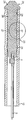
도 4는 도 3의 A-A 선의 단면도이고;4 is a cross-sectional view taken along the line A-A of FIG. 3;
도 4a는 도 4에서 원으로 표시된 부분의 확대도이고;4A is an enlarged view of a portion circled in FIG. 4;
도 5는 막이 제거된 도 3의 센서의 도면이고;5 is a view of the sensor of FIG. 3 with the membrane removed;
도 6은 부착 메커니즘이 관찰가능한 도 3의 pCO2 센서의 변형예를 도시하고;6 shows a variant of the pCO 2 sensor of FIG. 3 in which an attachment mechanism is observable;
도 7은 본 발명의 일실시예에 따른 센서 디바이스의 평면도이고;7 is a plan view of a sensor device according to one embodiment of the invention;
도 8은 도 7의 센서 디바이스의 부분 측단면도이고;8 is a partial side cross-sectional view of the sensor device of FIG. 7;
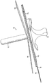
도 9는 사용 위치에서의 도 7 및 도 8의 센서 디바이스의 측면도이고;9 is a side view of the sensor device of FIGS. 7 and 8 in a use position;
도 10은 도 7 내지 도 9의 센서 디바이스의 pCO2 및 온도 센서의 확대도이고;10 is an enlarged view of the pCO 2 and temperature sensor of the sensor device of FIGS. 7-9;
도 11은 본 발명의 대안적인 실시예에 따른 센서 디바이스를 도시하고;11 shows a sensor device according to an alternative embodiment of the invention;
도 12는 도 11의 센서 디바이스의 부분 단면 사시도이고;12 is a partial cross-sectional perspective view of the sensor device of FIG. 11;
도 13은 도 11 및 12의 센서 디바이스의 상세 단면도이고; 13 is a detailed cross-sectional view of the sensor device of FIGS. 11 and 12;
도 14는 삽입 바늘이 없는 도 11 내지 도 13의 센서 디바이스의 평면도이고;14 is a top view of the sensor device of FIGS. 11-13 without an insertion needle;
도 15는 도 14의 위치에서의 센서 디바이스의 사시도이다. 15 is a perspective view of the sensor device in the position of FIG. 14.
본 발명에 따르면, pCO2 센싱 시스템은 도 1에 도시된 바와 같이 센서 디바이스(50), 전자 표면 유닛(2) 및 모니터 유닛(3)을 포함한다. 센서 디바이스(50)는 결합된 pCO2 및 온도 센서 유닛(1) 및 두개의 펄스 산소측정 센서(54)들을 포함한다.According to the invention, the pCO 2 sensing system comprises a
도 7 내지 10은 본 발명의 일실시예에 따른 센서 디바이스(50)를 도시한다. 디바이스(50)는, 이하 상세히 기재될 두개의 반사(reflection) 펄스 산소측정 센서(54)들 및 하나의 센서 유닛(1)이 장착되어 있는 자가-접착 스트립(52)을 포함한다. 펄스 산소측정 센서들은 MAX FAST 접착 앞부분 센서들(adhesive forehead sensors)과 같은 캘리포니아 플리즌턴의 넬코르(Nellcor) 사로부터 상업적으로 입수가능한 형태가 될 수 있다. 자가-접착 스트립(52)에는 환자의 피부에 적용시 접착 스트립(52)의 접착 표면을 드러내기 위해 접착 스트립(52)으로부터 벗겨질 수 있는 방출(release) 스트립(56)이 제공된다. 센서 디바이스(50)에는 임의의 손상, 오염 또는 증발을 막기 위해 프로필렌 글리콜의 멸균 등장 수용액이 충전된 튜브(도시 않음) 내에 센서 유닛(1)이 패키징 제공된다. 7-10 illustrate a
센서 디바이스(50)는 핑거 그립(60)이 제공된 심축(mandrel)(58)을 포함한다. 심축(58)은 센서 유닛(1)으로부터의 케이블 연결부(6)들을 포함하는 유연성 덮개(sheath)(또는 카테터(catheter))(62) 내에 수용된다. 도 10에 도시된 바와 같이, 이의 말단 단부에서 심축(58)은 센서 유닛(1)과 맞물리고(engage), 뾰족한 센서 유닛(1)은 심축(58)의 핑거 그립(60)에 손으로 압력을 적용시켜 환자의 피부를 통해 박힐(driven) 수 있다. 이런 방식으로, 센서 유닛(1)은 환자의 근육 내에, 예를 들어 환자의 겨드랑이 밑에 위치된다. The
pCO2 센서 유닛(1)이 환자의 근육 내에 바르게 위치되었을 때, 심축(58)은 센서 디바이스(50)를 도 9에 도시된 배치로 남겨두면서 유연성 덮개(62)로부터 잡아당겨진다(withdraw). 센서 유닛(1)에 연결된 덮개(62) 및 케이블(6)들은 적소의 센서 유닛(1)으로 환자에게 불편이 있다 하더라도 거의 없는 충분한 유연성이다.When the pCO 2 sensor unit 1 is correctly positioned in the muscle of the patient, the
센서 유닛(1)은 환자의 피부에 접착되는 접착 스트립(52)에 의해 근육의 적소에 유지된다. 이와 동시에, 피부에 접착 스트립(52)을 접착시키면 펄스 산소측정 센서(54)들이 환자의 피부에 대해 이들의 사용 위치에 있게 된다. 펄스 산소측정 센서(54)들은 환자의 혈액 내 산소 포화 수준을 결정하기 위해 환자 혈액으로부터의 특정 파장 빛의 반사율을 측정한다. The
도 7에서 매우 명백히 나타낸 바와 같이, 펄스 산소측정 센서(54)들로부터, 그리고 센서 유닛(1)으로부터 전기적 연결부(64)들은 전자 표면 유닛(2)에 대한 연결을 위해 접착 스트립(52)을 따라 길이방향으로 진행된다(run). 대안적으로, 도 9에 도시된 바와 같이, 센서 디바이스(50)에 전자 표면 유닛(2) 또는 모니터 유닛(3)과의 연통을 위해 무선 디바이스(70)가 제공될 수 있다. As very clearly shown in FIG. 7, the
센서 디바이스(50)는 패키징 및 멸균 전달된다. 센서 디바이스(50)는 센서 유닛(1) 내에 통합된, 직경 1 mm 이하의 막-보호된 전도도(conductometric) 센서(4) 및 온도 프로브(5)를 포함한다. 와이어(6)는 센서(4) 및 프로브(5)를 커넥터에 의해 전기적으로 전자 표면 유닛(2)에 연결한다. The
전자 표면 유닛(2)은 센서 디바이스(50)으로 및 이로부터 신호들을 송신 및 수신한다. 이는 환자의 피부 상에 위치되고, 센서 유닛(1)으로부터 신호들의 신호 처리를 수행하며, 컨디셔닝된 신호를 모니터 유닛(5)에 전송한다.
모니터 유닛(3)은 PCMCIA 입력/출력 카드(8) 및 랩뷰(Labview) 소프트웨어(텍사스 오스틴의 네셔널 인스트루먼트사 제)를 갖는 휴대용 퍼스널 컴퓨터(7)에 근거한다. The
pCO2 센서(4)는 도 2에 도시된 측정 원리에 따라 조직 내 CO2(pCO2)의 수준(부분압)을 측정하기 위해 사용된다. 측정 챔버는 각각에 한 개의 전극(10)이 위치되어 있는 두 개의 작은 캐비티(9)들로 구성된다. 두 캐비티(9)들은 반-투과성 막(12), 즉 센서(4)의 볼륨 안팎으로 CO2의 수송만이 가능한 막으로 둘러싸인 하나 이상의 통로(11)에 의해 연결되어 있다. 전체 볼륨은 탈이온수 및 5 %의 프로필렌 글리콜로 충전되어 있다. 물에서의 전도도는 pCO2에 따라 좌우되고, 볼륨 내 전극(10)들 간의 전도도를 측정함으로써 pCO2에 대한 정보가 얻어질 수 있다. The pCO 2 sensor 4 is used to measure the level (partial pressure) of CO 2 (pCO 2 ) in the tissue according to the measuring principle shown in FIG. 2. The measuring chamber consists of two
도 3 내지 5에 도시된 바와 같이, 센서 유닛(1)은 실질적으로 원통형이고 반-투과성 막(12)으로 둘러싸인 사출 성형된 플라스틱 지지체(23)를 포함한다. 지지체(23)는 지지체의 말단 단부에서 뾰족한 선단(24)을 갖고, 상기 선단(24)으로부터 근위로 연장되는 본체부(25)를 갖는다. 본체부(25) 상에는 접착을 통해 두개의 금 전극(10)들이 장착되어 있다. 전극(10)들은 본체부(25)의 대항면들을 따라 길이방향으로 연장되어 있고, 본체부(25) 내 개별적인 후퇴부들 내에 수용되어 있다. As shown in FIGS. 3 to 5, the
상기 선단(24) 및 본체부(25) 사이에는 마찰 맞춤(frictional fit)으로 막(12)을 고정(securing) 하기 위해 프러스토원뿔형(frustoconical) 돌출부(26)가 제공되어 있다. 대응하는 돌출부(26)가 본체부(25)의 근위 단부에 제공되어 있다. 막(12)은 지지체(23)에 접착될 수 있지만, 막(12) 및 전극(10)들을 고정하기 위해 사용된 접착제(glue)는 지지체(23)의 본체부(25) 및 막(12) 사이에 형성된 물-충전된 챔버 내에 이온들이 흘러나오지(bleed) 않도록 선택되는 것이 중요하다. 또한, 이온들이 흘러나올 수 있는 물 필름이 형성되는 것을 피하기 위해 지지체(23)의 시일링 면들(sealing faces)은 대안적으로 소수성으로 만들어질 수 있다. A
막(12)은 또한 필요하다면 주름 연결부(crimp connection) 및 연질(soft) 개스킷에 의해 지지체(23)에 고정될 수 있다. 특히 막(12)이 실리콘 고무로 형성되는 경우에 막(12)은 개스킷으로서 작용할 수 있다. 도 6의 경우에서와 같이, 주름 연결부를 형성하기 위해 열 수축 슬리브(sleave)가 사용될 수 있다. 대안적으로, 금속 주름 링들(rings)이 시일링 돌출부(26)의 위치들에 대응하는 위치들에서 사용될 수 있다. The
지지체(23)의 본체부(25)는 간단한 성형을 위한 톱니 프로파일로 형성되는 복수의 립(rib)(27)들이 제공되어 있다. 립(28)들은 막(12)에 대한 기계적 지지를 제공하고, 또한 센서(4)가 효과적으로 기능하기 위해 요구되는 유체 통로(11)를 정의한다. 각각의 전극(10) 및 립(27)들 사이에 형성된 유체 통로 사이에는 전극(10)이 위치되어 있는 후퇴부에 의해 형성되는 저장소(9)가 제공된다. 저장소(9)는 전기분극 효과를 감소시키기 위해 전극(10)들 주변에 비교적 낮은 전류 밀도의 영역을 제공한다. The
제조 시 막(12)은 지지체(23) 상에 고정되지만, 탈이온수 및 프로필렌 글리콜 용액 내에 침지되어, 막(12), 전극(10)들 및 립(27)들에 의해 결합된 챔버는 액체로 완전히 충전된다. 따라서, 이 챔버는 도 2에 개략적으로 도시된 바와 같은 pCO2 센서를 형성한다. The
센서(1)는 하나 이상의 센싱 챔버를 포함할 수 있다. 예를 들어, 벽 부재에 의해 분리된 두 개의 평행한 전극(10)들이 지지체(23)의 각 측면 상에 제공될 수 있다. 이에 의해, 지지체(23)의 최상부 상의 립(27)들 사이의 유체 통로(11)들을 통해 지지체(23)의 한쪽 상의 일 전극(10), 및 지지체(23)의 다른 한쪽 상의 전 극(10)들 중 하나 사이에 센싱 챔버가 형성된다. 대응하는 센싱 챔버는 지지체(11)의 최하부 상의 남아 있는 전극(10)들 및 유체 통로(11)들 사이에 제공된다. 센서로부터의 전기 신호가 두 챔버들 모두의 전도도를 반영하도록 이들 챔버들 각각으로부터의 전극(10)은 다른 챔버로부터의 대응하는 전극에 전기적으로 연결될 수 있다. The
지지체(23)의 근위 단부에 서모커플(thermocouple) 형태의 온도 센서(5)가 끼워넣어진다(embedded). pCO2 보정(corrective) 계산치들 및 측정된 조직 온도들 모두가 모니터(3) 상에 디스플레이되도록 온도 센서(5)가 사용되며, 이는 의학적 진단에 대한 정보가 된다. 온도 센서(5)는 33 - 42 ℃의 최소 측정 범위 및 +/- 0.2 ℃의 최소 정확도를 갖는다. At the proximal end of the support 23 a temperature sensor 5 in the form of a thermocouple is embedded. The temperature sensor 5 is used such that both pCO 2 corrective calculations and measured tissue temperatures are displayed on the
리본 케이블(ribbon cable)(6)은 전극(10)들 및 온도 센서(5)에 전기적 및 기계적으로 연결된다. 전극(10)들은 리본 케이블(6)의 컨덕터들의 연장부들(extensions)로서 형성된다. 대안적으로, 전극들은 지지체(23) 상에 도금에 의해 형성될 수 있다. 케이블(6) 및 지지체(23)에 대한 연결부가 충분히 강한 경우, 사용 위치로부터 센서 유닛(1)을 끌어당기기 위해 케이블(6)이 사용될 수 있다. 대안적으로, 강한 외부 기계적 결합을 제공하기 위해 케블러(Kevlar) 선이 제공, 예를 들어 리본 케이블(6)과 통합될 수 있다.A
케이블(6) 주위에 카테터를 형성하기 위해 막(12)은 케이블(6)을 갖는 지지체(23)로부터 근위로 연장될 수 있다. 대안적으로, 개별 카테터(28)가 제공될 수 있다. 이 경우, 카테터(28)는 막(12)과 전극(10)들의 근위에서 지지체(23)에 결합된다. The
도 6에서 알 수 있는 바와 같이, 조직 내 적소에 센서 유닛(1)을 고정하기 위해 카테터(28)에는 복수의 슬릿(29)들이 제공될 수 있다. 카테터(28)가 케이블(6)(또는 케블러 선)에 대해 원위로 (도 6의 화살표(B) 방향으로) 밀릴 때(pushed), 슬릿(29)들 사이의 카테터(28)의 일부분(30)들은 외부로 가압되고 도 6의 점선(phantom)으로 나타낸 형태를 띤다. 카테터(28)의 방사상 돌출부(30)들은 센서 유닛(1)이 끼워 넣어진 조직 내에 센서 유닛(1)을 유지한다. 카테터(28) 및 케이블(6)의 상대적인 위치는 센서 유닛(1)이 조직으로부터 제거될 때까지 고정(locking) 메커니즘(도시 않음)으로 유지될 수 있다. 이 때, 고정 메커니즘은 해제될 수 있으며, 카테터(28)의 일부분(30)들은 이의 이완된 위치로 되돌아가 센서 유닛(1)이 조직으로부터 제거될 수 있을 것이다. As can be seen in FIG. 6, a plurality of
통합된 센서(4)를 갖는 카테터 선단(tip)은 4주 이하의 기간동안 상기된 질환 및 이상의 치료 효과를 검출하고 모니터하기 위해 pCO2를 측정하도록 외과적 절차들 동안 장기 조직 내 0.5 내지 4 cm에 위치된다. A catheter tip with an
센서 유닛(1)은 1 mm의 최대 직경을 가지며, 카테터 선단으로부터 센서 요소까지의 최대 거리는 2 mm이다. 센서(4)는 2 내지 25 kPa의 최소 pCO2 측정 범위와 0.2 kPa의 최소 검출가능한 pCO2 차이를 갖는다. 센서(4)의 최대 반응은 20초이다. 유체 챔버의 임의의 영역에서의 최대 허용가능한 측정 전류는 j < 1 mA/cm2인 반면, 측정 입력 전압은 50 mV RMS 이하이다. The
전극(10)들은 금도금되고, 이들의 총 면적은 약 0.3 mm2이다. 측정 주파수(fmeas)는 100 Hz 이상이 되어야 한다. 낮은 주파수들에서는, 측정 챔버 내 편극 효과가 측정치들을 좌우한다. 10 kHz 이상의 주파수에서는 커패시터들의 낮은 임피던스가 큰 문제가 될 수 있다. 측정 저항(R_측정)은 500 kOhm 내지 7 MOhm 범위이다. The
센서(4)는 5 cm 내지 1 m 길이를 갖는 리본 케이블(6)에 의해 환자의 피부 상에 위치된 전자 표면 유닛(2)에 전기적으로 연결된다. 케이블/카테터의 최대 직경은 1 mm이다. 케이블/카테터는 이웃하는 조직에 과도하게 장애를 일으키지(disturb) 않도록 연질이고 유연하다. 케이블/카테터 및 이의 연결부들은 또한 정상적 및 “비정상적” 사용 모두에 의해 유발될 수 있는 강한 끌어당기는 힘들을 견디도록 충분히 강하다. The
살균, 저장 및 수송 시에 센서 저장소로부터 물의 순손실(net loss)이 실질적으로 반드시 없도록 센서 유닛(1)은 탈이온되고, 살균되고 엔도톡신이 없는(endotoxin-free) 물로 덮인다. The
도 11 내지 15는 본 발명의 대안 실시예에 따른 센서 디바이스(50)를 도시한다. 달리 지시되는 경우를 제외하고는, 이 실시예의 배치는 도 7 내지 10과 관련하여 기재된 센서 디바이스에서와 동일하다. 앞선 실시예에서와 같이, 디바이스(50)는 상기된 바와 같은 센서 유닛(1) 및 두개의 반사 펄스 산소측정 센서(54)들이 장착되어 있는 자가-접착 스트립(52)을 포함한다. 자가-접착 스트립(52)에는 환자의 피부에 적용하기 위한 접착 스트립(52)의 접착 표면을 드러내기 위해 접착 스트립(52)으로부터 벗겨질 수 있는 방출 스트립(56)이 제공되어 있다. 센서 디바이스(50)에는 임의의 손상, 오염 또는 증발을 막기 위한 프로필렌 글리콜 멸균 등장 수용액이 충전된 멸균수-충전 튜브(72) 내에 센서 유닛(1)이 패키징 제공된다. 11-15 illustrate a
센서 디바이스(50)는 핑거 그립(60)이 제공된 U-섹션 삽입 바늘(74)을 포함한다. 패키징된 센서 디바이스(50)에서, 센서 유닛(1) 및 관련 케이블 연결부들은 삽입 바늘(74) 내 U-형 채널 내에 수용된다. 보호 튜브(72)가 제거되면, 핑거 그립(60)에 손으로 압력을 적용시켜 삽입 바늘(74)이 환자의 피부를 통해 박힐(driven) 수 있다. 이어서, 삽입 바늘(74)은 도 14에 도시된 일반적인 배치로 환자의 근육 내에 위치된 센서 유닛(1)을 남겨두고 센서 디바이스(50)로부터 제거될 수 있다. 삽입 바늘(74)의 U-형태는 바늘이 잡아당겨질(withdrawn) 때 바늘이 케이블 연결부(6)들로부터 센서 유닛(1)까지 풀어질 수 있도록 한다. The
도 13은 삽입 바늘(74) 및 센서 디바이스(50) 사이의 연결부들을 상세히 도시한다. 도 13에 도시된 바와 같이, U-섹션 삽입 바늘(74)은 핑거 그립(60) 내에 몰딩된다. 센서 디바이스(50)에는 자가-접착 스트립(52) 내에 정의된 오리피스(orifice) 상에 위치되고 이와 맞물리는 플라스틱 하우징(76)이 제공된다. 플라스틱 하우징(76)은 자가-접착 스트립(52)에 결합된다. 플라스틱 하우징(76)의 중심에는 삽입 바늘(74)이 통과하는 홀(hole)이 정의된다. 플라스틱 하우징(76)의 홀 상에서 삽입 바늘(74)에 대한 중심 홀을 갖는 디스크 형태의 금속 가이드(78)가 플라스틱 하우징(76)에 결합된다. 금속 가이드(78)의 중심 홀은 삽입 바늘(74)의 단 면에 대응하는 U-형을 가지며, 바늘(74)이 회전하여 연결부(6)들 내지 센서 유닛(1) 까지 손상을 일으킬 수 없도록 바늘(74)을 적소에 유지하도록 작용한다. 센서 유닛(1)으로부터의 케이블 연결부(6)들은 금속 가이드(78) 및 플라스틱 하우징(76) 사이를 삽입 바늘(74)로부터 통과하고, 금속 가이드(78)에 접착된(glued) 보호 덮개(62)에 의해 둘러싸인다. 금속 가이드(78) 및 플라스틱 하우징(76)을 통한 홀은 금속 가이드 상에 제공되고, 삽입 바늘(74)이 통과하는 실리콘 막(80)에 의해 폐쇄된다. 실리콘 막(80)은 삽입 바늘(74)이 제거될 때 홀들을 시일하도록 탄성 변형된다. 13 shows in detail the connections between the
도 13에 도시된 바와 같이, 커버 튜브(72)의 요철형 가장자리(beaded rim)(82)는 플라스틱 하우징(76) 내 대응하는 후퇴부 내에 찰깍하고 끼워맞춰(snap fits) 튜브(72)를 센서 디바이스(50)에 밀봉한다. 튜브(72)는 센서 유닛(1)이 환자의 근육 내에 삽입되려 할 때 센서 디바이스(50)로부터 제거되어 삽입 바늘(74)을 노출시킨다. As shown in FIG. 13, the
도 1 및 2에 도시된 바와 같이, 전자 표면 유닛(2)은 5 V 이상의 전압 및 50 mV의 전류 공급을 제공하는 사인 발생기(13)를 포함하며, 배터리(14)들에 의해 동력 공급된다(powered). 록-인 증폭기(16)의 입력을 여과 또는 평준화(averaging) 하기 위해 필터(15)가 제공된다. 전류 소비를 감소시키는 수동 필터가 사용될 수 있다. 신호로부터 DC 전류를 제거하여 전기분해 효과들을 감소시키기 위해 예비-증폭기(pre-amplifier)(17)가 서보(servo) 메커니즘과 결합된다. 서보 배치에 따르면, 예비-증폭기의 출력이 로 패스 필터(low pass filter)를 통해 입력으로 다시 공급된다. 따라서, 출력의 DC 구성요소들만이 다시 공급되고, pCO2 센서를 통한(drawn through) 임의의 DC 전류는 제거된다(cancel). 이런 방식으로, 전극들을 열화시키는 pCO2 센서를 통한 DC 전류가 없도록 보장된다. 이 단계에서 사용된 op-amp는 최소 전류를 소비하고 큰 CMMR 값을 갖는다. 이와 동시에, 바이어스 전류는 최소이다. 록-인 증폭기(16)는 센서(4)로부터의 AC 신호를 증폭한다. 이는 op-amp들로 또는 1 kHz 이하의 주파수들에서 신호 검출에 대해 1 % 이하의 정확도를 갖는 IC 패키지를 사용하여 만들어질 수 있다. 모니터 유닛(3) 및 관련 케이블링(cabling)(18)으로부터 잡음 이동을 막기 위해 옵토커플러(optocoupler) 또는 코일 커플러와 같은 갈바닉 구획(galvanic division)(19)이 제공된다. 옵토커플러는 잡음 신호 비율(noise signal ratio)로 인해 일반적으로 유리하다. 온도 신호 증폭 및 컨디셔닝 유닛(20)이 온도 센서(5)로부터의 신호를 증폭하기 위해 제공된다. 전자 유닛(2)은 재충전가능하고 바꿀 수 있는 표준형 배터리(14)에 의해 전력 공급된다. 배터리 용량은 14일 연속 모니터링에 충분하다. 표면 유닛(2)은 또한 온/오프 표시기(LED)(21), 및 배터리 상태 표시기(도시 않음)가 제공된다. 표면 유닛(2) 및 모니터(3) 간의 연통은 차폐된 케이블(18)을 통한 아날로그이다. 그러나, 예를 들어 디지털 유선(wire) 전송 또는 디지털 무선 전송에 의해 표면 유닛(2) 및 모니터(3) 간의 연통이 디지털이 될 수 있도록 표면 유닛(2)은 아날로그 디지털 변환기(analog to digital converter)를 포함할 수 있다. 케이블(18)은 길이 4 m 이상이고 가볍고 유연하다.As shown in FIGS. 1 and 2, the
도 1 및 2에 도시된 바와 같이, AC 전류는 사인 발생기(13)에 의해 발생되고 pCO2 센서 전극(10)들 중 하나 및 록-인 증폭기(16)에 공급된다. 다른 pCO2 전극(10)으로부터의 하이-패스(high-pass) 신호는 사인 발생기(13)에 의해 발생된 기준 신호(reference signal)와 비교하여 필터(15)를 통해 저잡음(low noise) 증폭기(17)로 및 이로부터 록-인 증폭기(16)로 통과된다. 신호의 위상 구성요소들 중에서, 즉 불필요한 구성요소들은 거부되고 신호의 남아있는 일부분은 증폭된다. 증폭된 신호는 pCO2(또는 컨덕턴스)에 비례하고, 기록 및 추가 조작을 위해 모니터(3)로 보내어진다. As shown in FIGS. 1 and 2, the AC current is generated by the
표면 유닛(2)은 또한 환자의 피부에 전기적으로 연결되는 기준 전극(도시 않음)에 전기적으로 연결될 수 있다. 기준 전극으로부터의 신호는 환자에 의해 발생된 전자기적 노이즈의 작용에 대해 센서 유닛(1)으로부터의 신호들을 보정(compensate)하기 위해 사용될 수 있다. The
단일 표면 유닛(2)은 수 개의 센서 유닛(1)들로부터의 신호들을 수신할 수 있으며, 모니터 유닛(3)으로의 다중송신 출력(multiplexed output)을 제공할 수 있다. The
모니터 유닛(3)은 CD RW 및 IR 포트를 포함하는 휴대용 PC(7), 및 네 개 이상의 상이한 표면 유닛(2)들로부터의 신호들을 동시에 수집할 수 있는 PCMCIA I/O 카드(8)를 포함한다. PCMCIA 카드(8)는 통합된 비-갈바닉 커플링(coupling)을 가질 수 있다. 모니터 유닛(3)의 전원 공급기(22)는 110 V 및 230 V 모두에서 작동하는 의료적으로 승인된 형태이다. The
모니터 유닛(3)의 소프트웨어 기능들(functions)은 텍사스 오스틴의 네셔널 인스트루먼트사로부터 입수가능하고 네 개 이하의 상이한 표면 유닛들을 동시에 취급할 수 있는 소프트웨어 패키지인 랩뷰(Labview)로 충족될 수 있다. 소프트웨어는 세 보정 점들(calibration points) 및 이차 보정 함수(second order calibration function)를 갖는 센서(들)의 보정의 기능(facility)을 제공한다. 소프트웨어는 보정 점들의 어떤 다른 개수 및 보정 함수의 형태를 지원(support) 하기 위해 변형될 수 있다. 소프트웨어는 또한 정의된 시간 간격들에 걸쳐 센서 디바이스(50)로부터의 신호를 평탄하게(smooth) 하기 위한 설비(facility)를 갖는다. 측정 값들에 대한 둘 이상의 경보 수준들 및 이들의 구배들(gradients)에 대한 두 경보 수준들을 가질 수 있다. 개별적으로 정의된 시간 간격들에 대해 측정 값 구배들이 계산된다. 경보는 시각(visible) 및 청각(audible) 모두이다. 다른 경보를 활성으로 유지하면서 한 경보 표시를 중단시킬 수 있다. 모니터(3)는 한 세션 전반에 걸친 모든 측정된 값들, 파라미터 설정들 및 경보들을 로그(log) 할 수 있다. 30초의 로깅 간격으로, 하드 디스크 상에 10 이상의 2주 세션들에 대한 저장 용량이 있어야 한다. 세션 로그는 마이크로소프트 엑셀에 의해 판독가능한 포멧으로 쓸 수 있는(writeable) CD에 저장될 수 있다. The software functions of the
본 발명의 이 실시예에 따른 센서 디바이스(50)는 단일 디바이스 내에 환자 근육의 pCO2, 온도 및 혈액 산소화의 측정을 제공할 수 있다. 이러한 정보로, 의사 는 다른 이상들 가운데에서 환자의 패혈증의 발병을 신속 및 정확하게 확인할 수 있다. The
본 명세서에서 pCO2의 측정을 특히 참조하여 센서 디바이스를 개시하였으나, 상기 센서 디바이스의 일반적인 배치는 예를 들어, 체온, 산소의 부분압, pH 또는 글루코오스 농도와 같은 다른 생리학적 센서들에 대해 사용될 수 있다.Although a sensor device has been disclosed herein with particular reference to the measurement of pCO 2 , a general arrangement of the sensor device can be used for other physiological sensors such as, for example, body temperature, partial pressure of oxygen, pH or glucose concentration. .
Claims (12)
Applications Claiming Priority (2)
| Application Number | Priority Date | Filing Date | Title |
|---|---|---|---|
| GB0419958.4 | 2004-09-08 | ||
| GB0419958A GB0419958D0 (en) | 2003-10-20 | 2004-09-08 | Sensor |
Publications (1)
| Publication Number | Publication Date |
|---|---|
| KR20070052781A true KR20070052781A (en) | 2007-05-22 |
Family
ID=35207357
Family Applications (1)
| Application Number | Title | Priority Date | Filing Date |
|---|---|---|---|
| KR1020077005433A Withdrawn KR20070052781A (en) | 2004-09-08 | 2005-09-08 | sensor |
Country Status (9)
| Country | Link |
|---|---|
| EP (1) | EP1788933A1 (en) |
| JP (1) | JP2008512162A (en) |
| KR (1) | KR20070052781A (en) |
| CN (1) | CN101026996A (en) |
| AU (1) | AU2005281502A1 (en) |
| BR (1) | BRPI0514953A (en) |
| CA (1) | CA2578078A1 (en) |
| NO (1) | NO20071363L (en) |
| WO (1) | WO2006027586A1 (en) |
Cited By (1)
| Publication number | Priority date | Publication date | Assignee | Title |
|---|---|---|---|---|
| WO2025018475A1 (en) * | 2023-07-20 | 2025-01-23 | 주식회사 슬로웨이브 | Apparatus for measuring bio-signal |
Families Citing this family (81)
| Publication number | Priority date | Publication date | Assignee | Title |
|---|---|---|---|---|
| US8730031B2 (en) | 2005-04-28 | 2014-05-20 | Proteus Digital Health, Inc. | Communication system using an implantable device |
| US8836513B2 (en) | 2006-04-28 | 2014-09-16 | Proteus Digital Health, Inc. | Communication system incorporated in an ingestible product |
| CA2789262C (en) | 2005-04-28 | 2016-10-04 | Proteus Digital Health, Inc. | Pharma-informatics system |
| US9198608B2 (en) | 2005-04-28 | 2015-12-01 | Proteus Digital Health, Inc. | Communication system incorporated in a container |
| US8802183B2 (en) | 2005-04-28 | 2014-08-12 | Proteus Digital Health, Inc. | Communication system with enhanced partial power source and method of manufacturing same |
| US8912908B2 (en) | 2005-04-28 | 2014-12-16 | Proteus Digital Health, Inc. | Communication system with remote activation |
| WO2007028035A2 (en) | 2005-09-01 | 2007-03-08 | Proteus Biomedical, Inc. | Implantable zero-wire communications system |
| US8956287B2 (en) | 2006-05-02 | 2015-02-17 | Proteus Digital Health, Inc. | Patient customized therapeutic regimens |
| US8054140B2 (en) | 2006-10-17 | 2011-11-08 | Proteus Biomedical, Inc. | Low voltage oscillator for medical devices |
| SG175681A1 (en) | 2006-10-25 | 2011-11-28 | Proteus Biomedical Inc | Controlled activation ingestible identifier |
| US8718193B2 (en) | 2006-11-20 | 2014-05-06 | Proteus Digital Health, Inc. | Active signal processing personal health signal receivers |
| EP3785599B1 (en) | 2007-02-01 | 2022-08-03 | Otsuka Pharmaceutical Co., Ltd. | Ingestible event marker systems |
| WO2008101107A1 (en) | 2007-02-14 | 2008-08-21 | Proteus Biomedical, Inc. | In-body power source having high surface area electrode |
| EP2063771A1 (en) | 2007-03-09 | 2009-06-03 | Proteus Biomedical, Inc. | In-body device having a deployable antenna |
| WO2008112577A1 (en) | 2007-03-09 | 2008-09-18 | Proteus Biomedical, Inc. | In-body device having a multi-directional transmitter |
| US8540632B2 (en) | 2007-05-24 | 2013-09-24 | Proteus Digital Health, Inc. | Low profile antenna for in body device |
| US8961412B2 (en) | 2007-09-25 | 2015-02-24 | Proteus Digital Health, Inc. | In-body device with virtual dipole signal amplification |
| EP3235491B1 (en) | 2008-03-05 | 2020-11-04 | Proteus Digital Health, Inc. | Multi-mode communication ingestible event markers and systems |
| EP2313002B1 (en) | 2008-07-08 | 2018-08-29 | Proteus Digital Health, Inc. | Ingestible event marker data framework |
| CN102176862B (en) | 2008-08-13 | 2014-10-22 | 普罗透斯数字保健公司 | Ingestible circuitry |
| EP2349445A4 (en) | 2008-11-13 | 2012-05-23 | Proteus Biomedical Inc | Ingestible therapy activator system and method |
| CA2746650A1 (en) | 2008-12-11 | 2010-06-17 | Proteus Biomedical, Inc. | Evaluation of gastrointestinal function using portable electroviscerography systems and methods of using the same |
| US9439566B2 (en) | 2008-12-15 | 2016-09-13 | Proteus Digital Health, Inc. | Re-wearable wireless device |
| TWI424832B (en) | 2008-12-15 | 2014-02-01 | 波提亞斯數位康健公司 | Body related receiver and method thereof |
| US9659423B2 (en) | 2008-12-15 | 2017-05-23 | Proteus Digital Health, Inc. | Personal authentication apparatus system and method |
| JP5300984B2 (en) * | 2008-12-22 | 2013-09-25 | ラジオメーター・メディカル・アー・ペー・エス | Flat sensor |
| SG172847A1 (en) | 2009-01-06 | 2011-08-29 | Proteus Biomedical Inc | Pharmaceutical dosages delivery system |
| JP2012514799A (en) | 2009-01-06 | 2012-06-28 | プロテウス バイオメディカル インコーポレイテッド | Methods and systems for ingestion related biofeedback and individual pharmacotherapy |
| US9041541B2 (en) | 2010-01-28 | 2015-05-26 | Seventh Sense Biosystems, Inc. | Monitoring or feedback systems and methods |
| US9295417B2 (en) | 2011-04-29 | 2016-03-29 | Seventh Sense Biosystems, Inc. | Systems and methods for collecting fluid from a subject |
| WO2010101626A1 (en) | 2009-03-02 | 2010-09-10 | Seventh Sense Biosystems, Inc. | Techniques and devices associated with blood sampling |
| WO2010101625A2 (en) * | 2009-03-02 | 2010-09-10 | Seventh Sense Biosystems, Inc. | Oxygen sensor |
| US9033898B2 (en) | 2010-06-23 | 2015-05-19 | Seventh Sense Biosystems, Inc. | Sampling devices and methods involving relatively little pain |
| GB2480965B (en) | 2009-03-25 | 2014-10-08 | Proteus Digital Health Inc | Probablistic pharmacokinetic and pharmacodynamic modeling |
| WO2010129288A2 (en) | 2009-04-28 | 2010-11-11 | Proteus Biomedical, Inc. | Highly reliable ingestible event markers and methods for using the same |
| EP2432458A4 (en) | 2009-05-12 | 2014-02-12 | Proteus Digital Health Inc | Ingestible event markers comprising an ingestible component |
| EP2467707A4 (en) | 2009-08-21 | 2014-12-17 | Proteus Digital Health Inc | Apparatus and method for measuring biochemical parameters |
| TWI517050B (en) | 2009-11-04 | 2016-01-11 | 普羅托斯數位健康公司 | System for supply chain management |
| UA109424C2 (en) | 2009-12-02 | 2015-08-25 | PHARMACEUTICAL PRODUCT, PHARMACEUTICAL TABLE WITH ELECTRONIC MARKER AND METHOD OF MANUFACTURING PHARMACEUTICAL TABLETS | |
| EP2531099B1 (en) | 2010-02-01 | 2018-12-12 | Proteus Digital Health, Inc. | Data gathering system |
| CN102905672B (en) | 2010-04-07 | 2016-08-17 | 普罗秋斯数字健康公司 | Miniature ingestible device |
| TWI557672B (en) | 2010-05-19 | 2016-11-11 | 波提亞斯數位康健公司 | Computer system and computer-implemented method to track medication from manufacturer to a patient, apparatus and method for confirming delivery of medication to a patient, patient interface device |
| CN101822859B (en) * | 2010-06-08 | 2012-03-07 | 中国人民解放军军事医学科学院卫生装备研究所 | Closed loop control device for low blood volume shock liquid resuscitation |
| WO2011156095A2 (en) | 2010-06-10 | 2011-12-15 | The Regents Of The University Of California | Textile-based printable electrodes for electrochemical sensing |
| US20120016308A1 (en) | 2010-07-16 | 2012-01-19 | Seventh Sense Biosystems, Inc. | Low-pressure packaging for fluid devices |
| US20120039809A1 (en) | 2010-08-13 | 2012-02-16 | Seventh Sense Biosystems, Inc. | Systems and techniques for monitoring subjects |
| WO2012064802A1 (en) | 2010-11-09 | 2012-05-18 | Seventh Sense Biosystems, Inc. | Systems and interfaces for blood sampling |
| EP2642983A4 (en) | 2010-11-22 | 2014-03-12 | Proteus Digital Health Inc | Ingestible device with pharmaceutical product |
| JP2014514032A (en) | 2011-03-11 | 2014-06-19 | プロテウス デジタル ヘルス, インコーポレイテッド | Wearable personal body-related devices with various physical configurations |
| JP6121400B2 (en) | 2011-04-29 | 2017-04-26 | セブンス センス バイオシステムズ,インコーポレーテッド | Delivery and / or receipt of fluid |
| US20130158468A1 (en) | 2011-12-19 | 2013-06-20 | Seventh Sense Biosystems, Inc. | Delivering and/or receiving material with respect to a subject surface |
| EP3236259A1 (en) | 2011-04-29 | 2017-10-25 | Seventh Sense Biosystems, Inc. | Plasma or serum production and removal of fluids under reduced pressure |
| US9756874B2 (en) | 2011-07-11 | 2017-09-12 | Proteus Digital Health, Inc. | Masticable ingestible product and communication system therefor |
| WO2015112603A1 (en) | 2014-01-21 | 2015-07-30 | Proteus Digital Health, Inc. | Masticable ingestible product and communication system therefor |
| KR101898964B1 (en) | 2011-07-21 | 2018-09-14 | 프로테우스 디지털 헬스, 인코포레이티드 | Mobile communication device, system, and method |
| JP2014533523A (en) | 2011-09-02 | 2014-12-15 | ザ レジェンツ オブ ザ ユニヴァーシティー オブ カリフォルニア | Microneedle arrays for biosensing and drug delivery |
| US9235683B2 (en) | 2011-11-09 | 2016-01-12 | Proteus Digital Health, Inc. | Apparatus, system, and method for managing adherence to a regimen |
| CN104487347B (en) | 2012-07-23 | 2017-09-01 | 普罗秋斯数字健康公司 | Method and system for manufacturing the tablet for including electronic device |
| CA2888871C (en) | 2012-10-18 | 2016-08-09 | Proteus Digital Health, Inc. | Apparatus, system, and method to adaptively optimize power dissipation and broadcast power in a power source for a communication device |
| WO2014120669A1 (en) | 2013-01-29 | 2014-08-07 | Proteus Digital Health, Inc. | Highly-swellable polymeric films and compositions comprising the same |
| JP6498177B2 (en) | 2013-03-15 | 2019-04-10 | プロテウス デジタル ヘルス, インコーポレイテッド | Identity authentication system and method |
| US10175376B2 (en) | 2013-03-15 | 2019-01-08 | Proteus Digital Health, Inc. | Metal detector apparatus, system, and method |
| JP6511439B2 (en) | 2013-06-04 | 2019-05-15 | プロテウス デジタル ヘルス, インコーポレイテッド | Systems, devices, and methods for data collection and outcome assessment |
| EP3025263A2 (en) * | 2013-07-26 | 2016-06-01 | Koninklijke Philips N.V. | Computerization and visualization of clinical rules and definitions for patient monitoring systems. |
| US9796576B2 (en) | 2013-08-30 | 2017-10-24 | Proteus Digital Health, Inc. | Container with electronically controlled interlock |
| RU2736776C2 (en) | 2013-09-20 | 2020-11-20 | Протеус Диджитал Хелс, Инк. | Methods, devices and systems for receiving and decoding signals in the presence of noise using sections and deformation |
| JP2016537924A (en) | 2013-09-24 | 2016-12-01 | プロテウス デジタル ヘルス, インコーポレイテッド | Method and apparatus for use with electromagnetic signals received at frequencies that are not accurately known in advance |
| US10084880B2 (en) | 2013-11-04 | 2018-09-25 | Proteus Digital Health, Inc. | Social media networking based on physiologic information |
| US11051543B2 (en) | 2015-07-21 | 2021-07-06 | Otsuka Pharmaceutical Co. Ltd. | Alginate on adhesive bilayer laminate film |
| CN108699585A (en) * | 2016-02-23 | 2018-10-23 | 皇家飞利浦有限公司 | Method for progress original place detection of addling to breast milk |
| EP4159113B1 (en) | 2016-06-10 | 2024-02-28 | TERUMO Kabushiki Kaisha | Oxygen measurement device |
| CN109843149B (en) | 2016-07-22 | 2020-07-07 | 普罗秋斯数字健康公司 | Electromagnetic sensing and detection of ingestible event markers |
| US10820831B2 (en) | 2016-10-26 | 2020-11-03 | Proteus Digital Health, Inc. | Methods for manufacturing capsules with ingestible event markers |
| US12109032B1 (en) | 2017-03-11 | 2024-10-08 | Biolinq Incorporated | Methods for achieving an isolated electrical interface between an anterior surface of a microneedle structure and a posterior surface of a support structure |
| US11045142B1 (en) | 2017-04-29 | 2021-06-29 | Biolinq, Inc. | Heterogeneous integration of silicon-fabricated solid microneedle sensors and CMOS circuitry |
| US12599337B1 (en) | 2017-08-08 | 2026-04-14 | Biolinq Incorporated | Method and system for confirmation of microneedle-based analyte-selective sensor insertion into viable tissue via electrical interrogation |
| EP3506533B1 (en) | 2017-12-29 | 2022-03-30 | Nokia Technologies Oy | Sensing apparatus and system |
| GB2631618B (en) | 2020-07-29 | 2025-05-14 | Biolinq Incorporated | Continuous analyte monitoring system with microneedle array |
| SE545874C2 (en) | 2021-05-08 | 2024-02-27 | Biolinq Incorporated | Fault detection for microneedle array based continuous analyte monitoring device |
| CN120857905A (en) | 2023-02-02 | 2025-10-28 | 比奥林公司 | Methods for improving sensor sensitivity in microneedle-based continuous analyte monitoring systems |
| CN119438334B (en) * | 2024-09-27 | 2025-07-01 | 国网黑龙江省电力有限公司牡丹江水力发电总厂 | Concrete saturation sensor based on relative water contact area of fully polarized electrode and monitoring method |
Family Cites Families (18)
| Publication number | Priority date | Publication date | Assignee | Title |
|---|---|---|---|---|
| US4615340A (en) * | 1985-02-27 | 1986-10-07 | Becton, Dickinson And Company | Sensor assembly suitable for blood gas analysis and the like and the method of use |
| IL89159A0 (en) * | 1989-02-02 | 1989-09-10 | Optical Chemical Tech Oct | Medical probe |
| ES2099182T3 (en) * | 1991-06-26 | 1997-05-16 | Ppg Industries Inc | ELECTROCHEMICAL SENSOR ASSEMBLY. |
| AT397458B (en) * | 1992-09-25 | 1994-04-25 | Avl Verbrennungskraft Messtech | SENSOR ARRANGEMENT |
| US5375604A (en) * | 1992-12-11 | 1994-12-27 | Siemens Medical Electronics, Inc. | Transportable modular patient monitor |
| DE4329898A1 (en) * | 1993-09-04 | 1995-04-06 | Marcus Dr Besson | Wireless medical diagnostic and monitoring device |
| US5474065A (en) * | 1994-04-04 | 1995-12-12 | Graphic Controls Corporation | Non-invasive fetal probe |
| US6058321A (en) * | 1995-09-07 | 2000-05-02 | Swayze; Claude R. | Instrument for continuously monitoring fetal heart rate and intermittently monitoring fetal blood pH and method of use |
| JPH10314149A (en) * | 1997-05-20 | 1998-12-02 | Casio Comput Co Ltd | Electric measuring instrument with replaceable probe, probe management method, and pulse oximeter |
| GB9815667D0 (en) * | 1998-07-17 | 1998-09-16 | Medinnova Sf | Device |
| AU2032400A (en) * | 1998-11-25 | 2000-06-19 | Ball Semiconductor Inc. | Monitor for interventional procedures |
| JP4189787B2 (en) * | 2001-03-06 | 2008-12-03 | 日本光電工業株式会社 | Biological information display monitor and system |
| JP2005501576A (en) * | 2001-05-07 | 2005-01-20 | カーディオセーフ・インターナショナル・アクチェンゲゼルシャフト | Patient monitoring configuration |
| DE10141732A1 (en) * | 2001-08-25 | 2003-03-06 | Horst Frankenberger | Method and device for long-term determination of the concentration of at least one substance in a body fluid |
| US6616614B2 (en) * | 2001-09-18 | 2003-09-09 | Keimar Corporation | Apparatus and method for ascertaining cardiac output and other parameters |
| US6879850B2 (en) * | 2002-08-16 | 2005-04-12 | Optical Sensors Incorporated | Pulse oximeter with motion detection |
| JP2006501899A (en) * | 2002-10-03 | 2006-01-19 | スコット・ラボラトリーズ・インコーポレイテッド | System and method for providing sensor fusion |
| AU2003282545A1 (en) * | 2002-10-09 | 2004-05-04 | Csp Technologies, Inc. | Lancet system including test strips and cassettes |
-
2005
- 2005-09-08 KR KR1020077005433A patent/KR20070052781A/en not_active Withdrawn
- 2005-09-08 JP JP2007530764A patent/JP2008512162A/en active Pending
- 2005-09-08 WO PCT/GB2005/003461 patent/WO2006027586A1/en not_active Ceased
- 2005-09-08 BR BRPI0514953-3A patent/BRPI0514953A/en not_active IP Right Cessation
- 2005-09-08 AU AU2005281502A patent/AU2005281502A1/en not_active Abandoned
- 2005-09-08 CN CNA2005800298151A patent/CN101026996A/en active Pending
- 2005-09-08 EP EP05778573A patent/EP1788933A1/en not_active Withdrawn
- 2005-09-08 CA CA002578078A patent/CA2578078A1/en not_active Abandoned
-
2007
- 2007-03-14 NO NO20071363A patent/NO20071363L/en not_active Application Discontinuation
Cited By (1)
| Publication number | Priority date | Publication date | Assignee | Title |
|---|---|---|---|---|
| WO2025018475A1 (en) * | 2023-07-20 | 2025-01-23 | 주식회사 슬로웨이브 | Apparatus for measuring bio-signal |
Also Published As
| Publication number | Publication date |
|---|---|
| JP2008512162A (en) | 2008-04-24 |
| CN101026996A (en) | 2007-08-29 |
| WO2006027586A1 (en) | 2006-03-16 |
| AU2005281502A1 (en) | 2006-03-16 |
| BRPI0514953A (en) | 2008-07-01 |
| CA2578078A1 (en) | 2006-03-16 |
| NO20071363L (en) | 2007-06-06 |
| EP1788933A1 (en) | 2007-05-30 |
Similar Documents
| Publication | Publication Date | Title |
|---|---|---|
| KR20070052781A (en) | sensor | |
| AU2003217230B2 (en) | Tissue monitoring system for intravascular infusion | |
| US20080319278A1 (en) | Sensor | |
| KR101223079B1 (en) | Electrochemical sensor for in-vivo or ex-vivo measurements of the carbon dioxide partial pressure of living tissue | |
| Rabkin et al. | Oxygen tension measurements using an oxygen polarographic electrode sealed in an implantable silastic tonometer: a new technique | |
| CN115175609B (en) | Membrane seals for physiological sensors | |
| HK40079221A (en) | Membrane sealing for a physiological sensor | |
| HK40079221B (en) | Membrane sealing for a physiological sensor |
Legal Events
| Date | Code | Title | Description |
|---|---|---|---|
| PA0105 | International application |
Patent event date: 20070307 Patent event code: PA01051R01D Comment text: International Patent Application |
|
| PG1501 | Laying open of application | ||
| PC1203 | Withdrawal of no request for examination | ||
| WITN | Application deemed withdrawn, e.g. because no request for examination was filed or no examination fee was paid |