KR20070045361A - Metal complexes, luminescent solids, organic EL elements and organic EL displays - Google Patents
Metal complexes, luminescent solids, organic EL elements and organic EL displays Download PDFInfo
- Publication number
- KR20070045361A KR20070045361A KR1020077007321A KR20077007321A KR20070045361A KR 20070045361 A KR20070045361 A KR 20070045361A KR 1020077007321 A KR1020077007321 A KR 1020077007321A KR 20077007321 A KR20077007321 A KR 20077007321A KR 20070045361 A KR20070045361 A KR 20070045361A
- Authority
- KR
- South Korea
- Prior art keywords
- atom
- organic
- group
- metal complex
- layer
- Prior art date
- Legal status (The legal status is an assumption and is not a legal conclusion. Google has not performed a legal analysis and makes no representation as to the accuracy of the status listed.)
- Withdrawn
Links
Images


Classifications
-
- C—CHEMISTRY; METALLURGY
- C07—ORGANIC CHEMISTRY
- C07F—ACYCLIC, CARBOCYCLIC OR HETEROCYCLIC COMPOUNDS CONTAINING ELEMENTS OTHER THAN CARBON, HYDROGEN, HALOGEN, OXYGEN, NITROGEN, SULFUR, SELENIUM OR TELLURIUM
- C07F15/00—Compounds containing elements of Groups 8, 9, 10 or 18 of the Periodic Table
-
- C—CHEMISTRY; METALLURGY
- C09—DYES; PAINTS; POLISHES; NATURAL RESINS; ADHESIVES; COMPOSITIONS NOT OTHERWISE PROVIDED FOR; APPLICATIONS OF MATERIALS NOT OTHERWISE PROVIDED FOR
- C09K—MATERIALS FOR MISCELLANEOUS APPLICATIONS, NOT PROVIDED FOR ELSEWHERE
- C09K11/00—Luminescent materials, e.g. electroluminescent or chemiluminescent
- C09K11/06—Luminescent materials, e.g. electroluminescent or chemiluminescent containing organic luminescent materials
-
- C—CHEMISTRY; METALLURGY
- C07—ORGANIC CHEMISTRY
- C07F—ACYCLIC, CARBOCYCLIC OR HETEROCYCLIC COMPOUNDS CONTAINING ELEMENTS OTHER THAN CARBON, HYDROGEN, HALOGEN, OXYGEN, NITROGEN, SULFUR, SELENIUM OR TELLURIUM
- C07F15/00—Compounds containing elements of Groups 8, 9, 10 or 18 of the Periodic Table
- C07F15/0006—Compounds containing elements of Groups 8, 9, 10 or 18 of the Periodic Table compounds of the platinum group
- C07F15/0086—Platinum compounds
- C07F15/0093—Platinum compounds without a metal-carbon linkage
-
- C—CHEMISTRY; METALLURGY
- C07—ORGANIC CHEMISTRY
- C07F—ACYCLIC, CARBOCYCLIC OR HETEROCYCLIC COMPOUNDS CONTAINING ELEMENTS OTHER THAN CARBON, HYDROGEN, HALOGEN, OXYGEN, NITROGEN, SULFUR, SELENIUM OR TELLURIUM
- C07F15/00—Compounds containing elements of Groups 8, 9, 10 or 18 of the Periodic Table
- C07F15/02—Iron compounds
-
- H—ELECTRICITY
- H05—ELECTRIC TECHNIQUES NOT OTHERWISE PROVIDED FOR
- H05B—ELECTRIC HEATING; ELECTRIC LIGHT SOURCES NOT OTHERWISE PROVIDED FOR; CIRCUIT ARRANGEMENTS FOR ELECTRIC LIGHT SOURCES, IN GENERAL
- H05B33/00—Electroluminescent light sources
- H05B33/12—Light sources with substantially two-dimensional [2D] radiating surfaces
- H05B33/14—Light sources with substantially two-dimensional [2D] radiating surfaces characterised by the chemical or physical composition or the arrangement of the electroluminescent material, or by the simultaneous addition of the electroluminescent material in or onto the light source
-
- H—ELECTRICITY
- H10—SEMICONDUCTOR DEVICES; ELECTRIC SOLID-STATE DEVICES NOT OTHERWISE PROVIDED FOR
- H10K—ORGANIC ELECTRIC SOLID-STATE DEVICES
- H10K85/00—Organic materials used in the body or electrodes of devices covered by this subclass
- H10K85/30—Coordination compounds
- H10K85/341—Transition metal complexes, e.g. Ru(II)polypyridine complexes
- H10K85/346—Transition metal complexes, e.g. Ru(II)polypyridine complexes comprising platinum
-
- C—CHEMISTRY; METALLURGY
- C09—DYES; PAINTS; POLISHES; NATURAL RESINS; ADHESIVES; COMPOSITIONS NOT OTHERWISE PROVIDED FOR; APPLICATIONS OF MATERIALS NOT OTHERWISE PROVIDED FOR
- C09K—MATERIALS FOR MISCELLANEOUS APPLICATIONS, NOT PROVIDED FOR ELSEWHERE
- C09K2211/00—Chemical nature of organic luminescent or tenebrescent compounds
- C09K2211/10—Non-macromolecular compounds
- C09K2211/1018—Heterocyclic compounds
- C09K2211/1025—Heterocyclic compounds characterised by ligands
- C09K2211/1029—Heterocyclic compounds characterised by ligands containing one nitrogen atom as the heteroatom
-
- C—CHEMISTRY; METALLURGY
- C09—DYES; PAINTS; POLISHES; NATURAL RESINS; ADHESIVES; COMPOSITIONS NOT OTHERWISE PROVIDED FOR; APPLICATIONS OF MATERIALS NOT OTHERWISE PROVIDED FOR
- C09K—MATERIALS FOR MISCELLANEOUS APPLICATIONS, NOT PROVIDED FOR ELSEWHERE
- C09K2211/00—Chemical nature of organic luminescent or tenebrescent compounds
- C09K2211/10—Non-macromolecular compounds
- C09K2211/1018—Heterocyclic compounds
- C09K2211/1025—Heterocyclic compounds characterised by ligands
- C09K2211/1044—Heterocyclic compounds characterised by ligands containing two nitrogen atoms as heteroatoms
-
- C—CHEMISTRY; METALLURGY
- C09—DYES; PAINTS; POLISHES; NATURAL RESINS; ADHESIVES; COMPOSITIONS NOT OTHERWISE PROVIDED FOR; APPLICATIONS OF MATERIALS NOT OTHERWISE PROVIDED FOR
- C09K—MATERIALS FOR MISCELLANEOUS APPLICATIONS, NOT PROVIDED FOR ELSEWHERE
- C09K2211/00—Chemical nature of organic luminescent or tenebrescent compounds
- C09K2211/10—Non-macromolecular compounds
- C09K2211/1018—Heterocyclic compounds
- C09K2211/1025—Heterocyclic compounds characterised by ligands
- C09K2211/1059—Heterocyclic compounds characterised by ligands containing three nitrogen atoms as heteroatoms
-
- C—CHEMISTRY; METALLURGY
- C09—DYES; PAINTS; POLISHES; NATURAL RESINS; ADHESIVES; COMPOSITIONS NOT OTHERWISE PROVIDED FOR; APPLICATIONS OF MATERIALS NOT OTHERWISE PROVIDED FOR
- C09K—MATERIALS FOR MISCELLANEOUS APPLICATIONS, NOT PROVIDED FOR ELSEWHERE
- C09K2211/00—Chemical nature of organic luminescent or tenebrescent compounds
- C09K2211/18—Metal complexes
- C09K2211/185—Metal complexes of the platinum group, i.e. Os, Ir, Pt, Ru, Rh or Pd
-
- H—ELECTRICITY
- H10—SEMICONDUCTOR DEVICES; ELECTRIC SOLID-STATE DEVICES NOT OTHERWISE PROVIDED FOR
- H10K—ORGANIC ELECTRIC SOLID-STATE DEVICES
- H10K2101/00—Properties of the organic materials covered by group H10K85/00
- H10K2101/10—Triplet emission
-
- H—ELECTRICITY
- H10—SEMICONDUCTOR DEVICES; ELECTRIC SOLID-STATE DEVICES NOT OTHERWISE PROVIDED FOR
- H10K—ORGANIC ELECTRIC SOLID-STATE DEVICES
- H10K50/00—Organic light-emitting devices
- H10K50/10—OLEDs or polymer light-emitting diodes [PLED]
- H10K50/11—OLEDs or polymer light-emitting diodes [PLED] characterised by the electroluminescent [EL] layers
Landscapes
- Chemical & Material Sciences (AREA)
- Organic Chemistry (AREA)
- Engineering & Computer Science (AREA)
- Materials Engineering (AREA)
- Crystallography & Structural Chemistry (AREA)
- Inorganic Chemistry (AREA)
- Electroluminescent Light Sources (AREA)
Abstract
본 발명은, 인광 발광을 나타내고, 유기 EL 소자나 조명 장치 등에 있어서의 발광 재료나 색 변환 재료 등으로서 바람직한 금속 착물 등을 제공하는 것을 목적으로 한다. 본 발명의 금속 착물은, 금속 원자와, 그 금속 원자에 대하여, 제 1 질소 원자, 제 2 질소 원자 및 제 3 질소 원자의 3 개의 질소 원자를 통해 3 자리에서 결합하는 3 자리 배위자와, 상기 금속 원자에 결합하는 1 자리 배위자를 갖고 이루어지는 것을 특징으로 한다. 하기 일반식 (1) 로 표시되는 양태가 바람직하다. An object of this invention is to show phosphorescence emission, and to provide a metal complex etc. which are suitable as a light emitting material, a color conversion material, etc. in organic electroluminescent element, a lighting apparatus, etc. The metal complex of this invention is a tridentate ligand couple | bonded at a trident via a metal atom, 3 nitrogen atoms of a 1st nitrogen atom, a 2nd nitrogen atom, and a 3rd nitrogen atom with respect to the metal atom, and the said metal It is characterized by consisting of a monodentate ligand bonded to an atom. The aspect represented by the following general formula (1) is preferable.

Description
본 발명은, 인광 발광을 나타내고, 유기 EL 소자, 조명 장치 등에 있어서의 발광 재료나 색 변환 재료 등으로서 바람직한 금속 착물, 발광성 고체, 그 금속 착물 내지 발광성 고체를 사용한 유기 EL 소자, 및 그 유기 EL 소자를 사용한 유기 EL 디스플레이에 관한 것이다. The present invention exhibits phosphorescence emission, and is an organic EL device using a metal complex, a luminescent solid, a metal complex or a luminescent solid, which is suitable as a luminescent material, a color conversion material or the like in an organic EL element, an illumination device, or the like, and the organic EL element It relates to an organic EL display using.
유기 EL 소자는, 1 층 내지 복수층의 얇은 유기물층을 부극(負極)과 정극(正極) 사이에 개재한 구조를 가지며, 상기 유기물층에 대하여, 상기 정극으로부터 정공을, 상기 부극으로부터 전자를 각각 주입하고, 그 정공과 그 전자가 상기 유기물층에서 재결합할 때의 재결합 에너지에 의해, 상기 유기물층 중의 발광 재료의 발광 중심을 여기(勵起)시키고, 그 발광 재료가 여기 상태로부터 기저 상태로 실활할 때 방출되는 광을 이용한 발광 소자이다. 그 유기 EL 소자는, 자발광, 고속 응답 등의 특징을 가지며, 시인성이 양호하고, 초박형, 경량이고, 고속 응답성, 동영상 표시성이 우수하므로, 풀컬러 디스플레이 등의 플랫 패널 디스플레이로의 적용이 기대되고 있다. 특히, 정공 수송성의 유기 박막 (정공 수송층) 과 전자 수송성의 유기 박막 (전자 수송층) 을 적층한 2 층형 (적층형) 의 유기 EL 소자가 보 고된 이래 (비특허 문헌 1 참조), 그 유기 EL 소자는, 10V 이하의 저전압으로 발광 가능한 대면적 발광 소자로서 주목받고 있다. The organic EL device has a structure in which one or more thin organic material layers are interposed between a negative electrode and a positive electrode, and holes are injected from the positive electrode and electrons are respectively injected into the organic material layer. And the light emission center of the light emitting material in the organic material layer is excited by recombination energy when the holes and the electrons recombine in the organic material layer, and are emitted when the light emitting material deactivates from the excited state to the ground state. It is a light emitting element using light. The organic EL device has characteristics such as self-luminous, high-speed response, good visibility, ultra-thin, light weight, high-speed responsiveness, and excellent video display, so that application to flat panel displays such as full-color displays is easy. It is expected. In particular, since a two-layer (laminated) organic EL device in which a hole transporting organic thin film (hole transporting layer) and an electron transporting organic thin film (electron transporting layer) are stacked (see Non-Patent Document 1) has been reported, the organic EL device has It is attracting attention as a large area light emitting device capable of emitting light at a low voltage of 10 V or less.
상기 유기 EL 소자에 있어서는, 발광 효율을 향상시키는 관점에서, 주재료인 형광 발광성의 호스트 재료에 대하여, 형광 발광성이 높은 색소 분자를 게스트 재료로서 소량 도프시켜, 높은 발광 효율을 나타내는 발광층을 형성하는 것이 제안되어 있다 (비특허 문헌 2 참조).In the above organic EL device, from the viewpoint of improving the luminous efficiency, it is proposed to form a light emitting layer exhibiting high luminous efficiency by doping a small amount of dye molecules having high fluorescence as a guest material with respect to a fluorescence luminescent host material as a main material. (See Non-Patent Document 2).
또한, 최근, 상기 형광 발광성 재료 대신에, 분자의 여기 삼중항 상태로부터의 발광을 이용하는 인광 발광성 재료를 유기 EL 소자의 발광 재료로 함으로써, 상기 유기 EL 소자의 발광 효율을 높이는 것이 가능할 것으로 나타나 주목을 받고 있다 (비특허 문헌 3 참조). 유기물로부터의 발광은, 발광을 일으키는 여기 상태의 성질에 따라 형광과 인광으로 분류된다. 지금까지, 일반적인 유기물은 실온에서는 인광을 발하지 않는다는 이유에서, 유기 EL 소자에서는 형광 발광성 재료가 이용되어 왔다. EL 발광 메카니즘으로부터는, 인광 발광 상태는 형광 발광 상태의 4 배의 확률로 생성될 것으로 예상되므로, 실온에서 인광 발광을 일으키는 중금속 착물의 발광 재료로의 적용이, EL 소자의 고효율화 수단으로서 최근 주목을 받고 있다. 그러나, 인광 발광성 재료의 경우, 실온에서 강한 인광을 발하는 재료가 상당히 적어, 재료의 선택폭이 좁다는 문제가 있다. In addition, it has recently been shown that it is possible to increase the luminous efficiency of the organic EL device by using a phosphorescent material using the light emission from the excited triplet state of the molecule instead of the fluorescent material as the light emitting material of the organic EL device. (Refer nonpatent literature 3). Light emission from organic substances is classified into fluorescence and phosphorescence according to the nature of the excited state causing light emission. Up to now, a fluorescent organic material has been used in organic EL devices because a general organic substance does not emit phosphorescence at room temperature. From the EL light emitting mechanism, the phosphorescent light emission state is expected to be generated four times as high as that of the fluorescent light emission state, and therefore, the application of heavy metal complexes causing phosphorescence at room temperature to the light emitting material has recently attracted attention as a means of increasing the efficiency of the EL element. I am getting it. However, in the case of the phosphorescent material, there is a problem that the material which emits strong phosphorescence at room temperature is considerably small, so that the selection range of the material is narrow.
실온에서 인광을 발하는 금속 착물을 사용한 유기 EL 소자의 공지예로는, 백금 원소와 질소 원자에 의한 배위 결합 2 개와, 백금 원소와 탄소 원자의 직접 결합 1 개로 이루어지는 N⌒N⌒C 형의 3 자리 배위자를 갖는 금속 착물이 일례로서 예시된다 (특허 문헌 1 참조). 그러나, 이 금속 착물은 실온에서의 인광 발광 효율이 충분하지 않고, 이 금속 착물을 사용한 유기 EL 소자의 경우, 발광 효율이 낮다는 문제가 있다. As a known example of an organic EL device using a metal complex which emits phosphorus at room temperature, a three-digit N⌒N⌒C type consisting of two coordination bonds by a platinum element and a nitrogen atom and one direct bond between a platinum element and a carbon atom The metal complex which has a ligand is illustrated as an example (refer patent document 1). However, this metal complex does not have sufficient phosphorescence emission efficiency at room temperature, and in the case of an organic EL element using this metal complex, there is a problem that the luminous efficiency is low.
비특허 문헌 1 : C.W.Tang and S.A.VanSlyke, Applied Physics Letters vol.51, 913 (1987)Non-Patent Document 1: C.W.Tang and S.A.VanSlyke, Applied Physics Letters vol. 51, 913 (1987)
비특허 문헌 2 : C.W.Tang, S.A.VanSlyke, and C.H.Chen, Journal of Applied Physics vol.65, 3610 (1989)Non-Patent Document 2: C.W.Tang, S.A.VanSlyke, and C.H.Chen, Journal of Applied Physics vol. 65, 3610 (1989)
비특허 문헌 3 : M.A.Baldo, et al., Nature vol.395, 151 (1998), M.A.Baldo, etal., Applied Physics Letters vol.75, 4 (1999)Non Patent Literature 3: M. A. Baldo, et al., Nature vol. 395, 151 (1998), M. A. Baldo, et al., Applied Physics Letters vol. 75, 4 (1999)
특허 문헌 1 : 일본 공개특허공보 2002-363552호Patent Document 1: Japanese Unexamined Patent Publication No. 2002-363552
발명의 개시Disclosure of the Invention
본 발명은, 종래에 있어서의 문제를 해결하고, 이하의 목적을 달성하는 것을 과제로 한다. 본 발명은, 인광 발광을 나타내고, 유기 EL 소자나 조명 장치 등에 있어서의 발광 재료나 색 변환 재료 등으로서 바람직한 금속 착물, 발광성 고체, 그 금속 착물 내지 발광성 고체를 사용하고, 수명, 발광 효율, 열적 및 전기적인 안정성이 우수하고, 구동 수명이 상당히 긴 유기 EL 소자, 및 그 유기 EL 소자를 사용하고, 고성능이며 수명이 길고, 평균 구동 전류를 발광 화소에 상관 없이 일정하게 할 수 있고, 발광 면적을 바꾸지 않고 색 밸런스가 양호한 풀컬러 디스플레이 등에 바람직하고, 구동 수명이 긴 유기 EL 디스플레이를 제공하는 것을 목적으로 한다. This invention solves the problem in the past, and makes it a subject to achieve the following objectives. The present invention exhibits phosphorescence emission and uses metal complexes, luminescent solids, metal complexes to luminescent solids which are suitable as light emitting materials, color converting materials, and the like in organic EL devices, lighting devices, and the like. Using an organic EL element having excellent electrical stability and a considerably long driving life, and the organic EL element, and having a high performance and a long lifetime, the average driving current can be made constant regardless of the light emitting pixels, and the light emitting area is not changed. It is an object of the present invention to provide an organic EL display which is suitable for a full color display having a good color balance and has a long driving life.
상기 과제를 해결하기 위해 발명자들이 예의 검토한 결과, 이하의 식견을 얻었다. 즉, 금속 원자와 N⌒N⌒N 형의 3 자리 배위자와 특정한 1 자리 배위자를 포함하는 금속 착물이 강한 인광 발광을 나타내고, 유기 EL 소자에 바람직한 양호한 승화성을 나타내고, 또한 진공 증착에 의해 양호한 neat 막, dope 막 등을 형성 가능하고, 유기 EL 소자나 조명 장치 등에 있어서의 발광 재료 등으로서 바람직하고, 그 금속 착물을 사용한 유기 EL 소자 및 유기 EL 디스플레이는, 수명, 발광 효율, 열적 및 전기적인 안정성 등이 우수하고, 구동 수명이 상당히 길고, 고성능이라는 식견이다. 본 발명은, 본 발명자들에 의한 상기 식견에 기초하는 것으로, 상기 과제를 해결하기 위한 본 발명은, 이하와 같다. As a result of earnestly examining by the inventors in order to solve the said subject, the following knowledge was obtained. That is, a metal complex containing a metal atom, a N⌒N⌒N type tridentate ligand, and a specific monodentate ligand exhibits strong phosphorescence, exhibits good sublimation properties preferable for an organic EL element, and satisfies neat by vacuum deposition. It is possible to form a film, a dope film, etc., and is preferable as a light emitting material in an organic EL element, an illumination device, etc., and the organic electroluminescent element and organic electroluminescent display using the metal complex have lifetime, luminous efficiency, thermal, and electrical stability. It is known that the back is excellent, the driving life is quite long, and high performance. This invention is based on the said knowledge by this inventor, The present invention for solving the said subject is as follows.
본 발명의 금속 착물은, 금속 원자와, 그 금속 원자에 대하여, 제 1 질소 원자, 제 2 질소 원자 및 제 3 질소 원자의 3 개의 질소 원자를 통해 3 자리에서 결합하는 3 자리 배위자와, 상기 금속 원자에 결합하는 1 자리 배위자를 갖고 이루어지는 것을 특징으로 한다. The metal complex of this invention is a tridentate ligand couple | bonded at a trident via a metal atom, 3 nitrogen atoms of a 1st nitrogen atom, a 2nd nitrogen atom, and a 3rd nitrogen atom with respect to the metal atom, and the said metal It is characterized by consisting of a monodentate ligand bonded to an atom.
유기물로부터의 발광은, 발광을 발생시키는 여기 상태의 성질에 따라 형광과 인광으로 분류되는데, 종래, 유기물은 일반적으로 인광을 발생하지 않는다는 이유에서, 유기 EL 소자나 조명 장치 등에 있어서의 발광 재료나 색 변환 재료 등으로는, 형광 발광 재료가 이용되어 왔다. 그러나, EL 발광 메카니즘으로부터는, 형광 발광 상태의 4 배의 확률로 인광 발광 상태가 생성될 것으로 예상되므로, 실온에서 인광 발광을 발생시키는 금속 착물의 발광 재료로의 적용이 EL 소자의 고효율화에는 유효하여, 최근 주목을 받고 있다. 본 발명의 상기 금속 착물로부터는, 상기 인광 발광이 강하게 발생하므로, 형광 발광 재료를 사용한 EL 소자의 내부 양자 효율이 최대 25% 인 것에 대해, 이론상, 최대 100% 라는 높은 발광 효율이 달성 가능하다. 이 때문에, 강한 인광 발광을 나타내는 상기 금속 착물은, 유기 EL 소자 등에 있어서의 발광 재료 등으로서 바람직하다. 본 발명의 금속 착물에 있어서는, 상기 금속 원자의 종류, 상기 3 자리 배위자 (N⌒N⌒N 형) 또는 상기 1 자리 배위자에 있어서의 골격 구조, 치환기 등의 종류나 수 등을 적절히 변경함으로써, 발광색을 바꿀 수 있다. Light emission from organic materials is classified into fluorescence and phosphorescence according to the nature of an excited state that generates light emission. Conventionally, organic materials generally do not generate phosphorescence, and therefore, light emitting materials and colors in organic EL devices, lighting devices, and the like. As the conversion material, a fluorescent light emitting material has been used. However, from the EL light emitting mechanism, the phosphorescent light emitting state is expected to be generated at four times the probability of the fluorescent light emitting state. Therefore, the application of the metal complex which generates the phosphorescent light emission at room temperature to the light emitting material is effective for the high efficiency of the EL element. , Recently attracting attention. Since the said phosphorescent light emission generate | occur | produces strongly from the said metal complex of this invention, while the internal quantum efficiency of the EL element using a fluorescent light emitting material is 25% at maximum, theoretically high high luminous efficiency of 100% can be achieved. For this reason, the said metal complex which shows strong phosphorescence emission is suitable as a light emitting material etc. in organic electroluminescent element etc. In the metal complex of this invention, light emission color is changed by changing suitably the kind of the said metal atom, the said tridentate ligand (N⌒N⌒N type), or a skeletal structure, substituent, etc. in the said monodentate ligand, etc. Can be changed.
본 발명의 발광성 고체는, 본 발명의 상기 금속 착물을 함유한다. 이 때문에, 본 발명의 금속 착물을 함유하는 본 발명의 발광성 고체는, 구동 수명이 상당히 길고, 수명, 발광 효율 등이 우수하여, 조명 장치, 디스플레이 장치 등에 바람직하게 사용할 수 있다. The luminescent solid of this invention contains the said metal complex of this invention. For this reason, the luminescent solid of this invention containing the metal complex of this invention is considerably long in driving life, and is excellent in lifetime, luminous efficiency, etc., and can be used suitably for a lighting apparatus, a display apparatus, etc.
본 발명의 유기 EL 소자는, 정극 및 부극 사이에 유기 박막층을 갖고 이루어지고, 그 유기 박막층이, 상기 금속 착물을 함유한다. 이 때문에, 본 발명의 금속 착물을 함유하는 본 발명의 유기 EL 소자는, 구동 수명이 상당히 길고, 수명, 발광 효율 등이 우수하여, 조명 장치, 디스플레이 장치 등에 바람직하게 사용할 수 있다. The organic EL element of this invention has an organic thin film layer between a positive electrode and a negative electrode, and this organic thin film layer contains the said metal complex. For this reason, the organic electroluminescent element of this invention containing the metal complex of this invention is considerably long in driving life, excellent in lifetime, luminous efficiency, etc., and can be used suitably for a lighting apparatus, a display apparatus, etc.
본 발명의 유기 EL 디스플레이는, 본 발명의 상기 유기 EL 소자를 사용하여 이루어진다. 이 때문에, 본 발명의 유기 EL 소자를 사용한 본 발명의 그 유기 EL 디스플레이는, 구동 수명이 상당히 길고, 수명, 발광 효율 등이 우수하다.The organic electroluminescent display of this invention is made using the said organic electroluminescent element of this invention. For this reason, the organic electroluminescent display of this invention using the organic electroluminescent element of this invention is considerably long in driving lifetime, and is excellent in lifetime, luminous efficiency, etc.
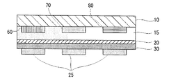
도 1 은, 본 발명의 유기 EL 소자에 있어서의 층구성의 일례를 나타내는 개략 설명도이다.BRIEF DESCRIPTION OF THE DRAWINGS It is a schematic explanatory drawing which shows an example of the laminated constitution in the organic electroluminescent element of this invention.
도 2 는, 유기 EL 디스플레이의 하나의 구조예를 나타내는 개략 설명도이다.2 is a schematic explanatory diagram showing one structural example of an organic EL display.
도 3 은, 유기 EL 디스플레이의 하나의 구조예를 나타내는 개략 설명도이다.3 is a schematic explanatory diagram showing one structural example of an organic EL display.
도 4 는, 유기 EL 디스플레이의 하나의 구조예를 나타내는 개략 설명도이다.4 is a schematic explanatory diagram showing one structural example of an organic EL display.
도 5 는, 패시브 매트릭스 방식의 유기 EL 디스플레이 (패시브 매트릭스 패널) 의 하나의 구조예를 나타내는 개략 설명도이다. 5 is a schematic explanatory diagram showing one structural example of an organic EL display (passive matrix panel) of a passive matrix system.
도 6 은, 도 5 에 나타내는 패시브 매트릭스 방식의 유기 EL 디스플레이 (패시브 매트릭스 패널) 에 있어서의 회로를 나타내는 개략 설명도이다. FIG. 6 is a schematic explanatory diagram showing a circuit in an organic EL display (passive matrix panel) of a passive matrix system shown in FIG. 5.
도 7 은, 액티브 매트릭스 방식의 유기 EL 디스플레이 (액티브 매트릭스 패널) 의 하나의 구조예를 나타내는 개략 설명도이다. 7 is a schematic explanatory diagram showing one structural example of an organic EL display (active matrix panel) of an active matrix system.
도 8 은, 도 7 에 나타내는 액티브 매트릭스 방식의 유기 EL 디스플레이 (액티브 매트릭스 패널) 에 있어서의 회로를 나타내는 개략 설명도이다.FIG. 8 is a schematic explanatory diagram showing a circuit in an organic EL display (active matrix panel) of an active matrix system shown in FIG. 7.
도 9 는, 인광 양자 수율을 산출하기 위한 실험의 개요를 설명하기 위한 개략도이다.9 is a schematic diagram for explaining an outline of an experiment for calculating phosphorescent quantum yield.
발명을 실시하기 위한 최선의 형태Best Mode for Carrying Out the Invention
(금속 착물)(Metal complex)
본 발명의 금속 착물은, 금속 원자와, 그 금속 원자에 대하여 3 자리에서 결합하는 특정한 3 자리 배위자와, 상기 금속 원자에 대하여 1 자리에서 결합하는 특 정한 1 자리 배위자를 갖는다. The metal complex of this invention has a metal atom, the specific tridentate ligand couple | bonded at the 3-position with respect to the metal atom, and the specific monodentate ligand couple | bonded at the 1 position with respect to the said metal atom.
-금속 원자-Metal atom
상기 금속 원자는, 상기 금속 착물에 있어서의 중심 금속으로서 작용하고, 그 금속 원자로는, 특별히 제한이 없고, 목적에 따라 적절히 선택할 수 있고, 예를 들어 Fe, Co, Ni, Ru, Rh, Pd, Os, Ir, Pt 등을 들 수 있다. The said metal atom acts as a center metal in the said metal complex, There is no restriction | limiting in particular as the metal atom, According to the objective, it can select suitably, For example, Fe, Co, Ni, Ru, Rh, Pd, Os, Ir, Pt, etc. are mentioned.
상기 금속 원자는, 상기 금속 착물 1 분자 중에 1 개 포함되고, 2 분자 이상의 상기 금속 착물에 있어서의 각 금속 원자는, 1 종 단독이어도 되고, 2 종 이상이어도 된다. 상기 금속 원자 중에서도, Pt 가 특히 바람직하다 (이 경우, 상기 금속 착물은 백금 착물이다).One said metal atom is contained in 1 molecule of said metal complex, 1 type may be sufficient as each metal atom in the said metal complex of 2 or more molecules, and 2 or more types may be sufficient as it. Among the above metal atoms, Pt is particularly preferred (in this case, the metal complex is a platinum complex).
-3 자리 배위자-3-digit ligands
상기 3 자리 배위자로는, 상기 금속 원자에 대하여, 제 1 질소 원자, 제 2 질소 원자 및 제 3 질소 원자의 3 개의 질소 원자를 통해 3 자리에서 결합하는 것 (N⌒N⌒N 형) 이면 특별히 제한은 없고, 목적에 따라 적절히 선택할 수 있다.As the tridentate ligand, in the case where the N-N-N type is bonded to the metal atom through three nitrogen atoms of the first nitrogen atom, the second nitrogen atom, and the third nitrogen atom, There is no restriction | limiting and it can select suitably according to the objective.
상기 3 자리 배위자로는, 예를 들어 상기 제 1 질소 원자 및 상기 제 3 질소 원자에 인접하고 또한 이들 사이에 위치하는 상기 제 2 질소 원자가 상기 금속 원자에 대하여 공유 결합에 의해 결합하고, 상기 제 1 질소 원자 및 상기 제 3 질소 원자가 상기 금속 원자에 대하여 배위 결합에 의해 결합하는 것이 바람직하고, 또한, 상기 제 1 질소 원자, 상기 제 2 질소 원자 및 상기 제 3 질소 원자의 3 개가, 각각 별도의 고리 구조의 일부인 것이 바람직하고, 상기 제 1 질소 원자를 포함하는 고리 구조에 있어서의 그 제 1 질소 원자에 인접하는 질소 인접 원자가, 상기 제 2 질소 원자를 포함하는 고리 구조에 있어서의 그 제 2 질소 원자에 인접하는 하나의 질소 인접 원자에 결합하고, 또한 상기 제 3 질소 원자를 포함하는 고리 구조에 있어서의 그 제 3 질소 원자에 인접하는 질소 인접 원자가, 상기 제 2 질소 원자를 포함하는 고리 구조에 있어서의 그 제 2 질소 원자에 인접하는 다른 질소 인접 원자에 결합한 것이 보다 바람직하고, 상기 하나의 질소 인접 원자 및 상기 다른 질소 인접 원자가 탄소 원자인 것이 더욱 더 바람직하고, 상기 제 1 탄소 인접 원자 및 상기 제 2 탄소 인접 원자가 모두 탄소 원자인 것이 특히 바람직하다. As the tridentate ligand, for example, the second nitrogen atom adjacent to and located between the first nitrogen atom and the third nitrogen atom is bonded by a covalent bond to the metal atom, and the first It is preferable that a nitrogen atom and the said 3rd nitrogen atom couple | bond by coordination bond with respect to the said metal atom, Furthermore, three of the said 1st nitrogen atom, the said 2nd nitrogen atom, and the said 3rd nitrogen atom are each separate rings It is preferable that it is a part of structure, and the nitrogen adjacent atom adjacent to the 1st nitrogen atom in the ring structure containing a said 1st nitrogen atom is the 2nd nitrogen atom in the ring structure containing the said 2nd nitrogen atom. To a third nitrogen atom in a ring structure bonded to one nitrogen adjacent atom adjacent to and further comprising the third nitrogen atom More preferably, the adjacent nitrogen adjacent atoms are bonded to another nitrogen adjacent atom adjacent to the second nitrogen atom in the ring structure containing the second nitrogen atom, and the one nitrogen adjacent atom and the other nitrogen adjacent valence carbon are more preferable. It is even more preferred that it is an atom, and it is particularly preferred that both the first and adjacent carbon atoms are carbon atoms.
-1 자리 배위자--1 seat ligand-
상기 1 자리 배위자로는, 상기 금속 원자에 대하여 1 자리에서 결합하는 것이면, 특별히 제한은 없고, 목적에 따라 적절히 선택할 수 있지만, 그 금속 착물의 안정성 면에서, 상기 금속 원자에 대하여, C 원자, N 원자, O 원자, P 원자 및 S 원자에서 선택되는 하나의 원자를 통해 결합하는 배위자가 바람직하고, 그 금속 착물에 승화성을 부여할 수 있다는 점에서, 상기 금속 착물 전체의 전하를 중성으로 할 수 있는 배위자가 바람직하다. The monodentate ligand is not particularly limited as long as the monodentate ligand is bonded at the monodentate to the metal atom, and may be appropriately selected according to the purpose. However, in view of the stability of the metal complex, C atom, N A ligand that bonds through one atom selected from an atom, an O atom, a P atom and an S atom is preferable, and the charge of the entire metal complex can be neutralized in that it can impart sublimation to the metal complex. Which ligand is preferred.
-금속 착물의 구체예-Specific examples of metal complexes
본 발명의 금속 착물의 구체예로는, 예를 들어 하기 일반식 (1) 로 표시되는 금속 착물 등을 바람직하게 들 수 있다. As a specific example of the metal complex of this invention, the metal complex etc. which are represented, for example by following General formula (1) are mentioned preferably.
[화학식 2] [Formula 2]

상기 일반식 (1) 에 있어서, M 은, 상기 기술한 금속 원자를 나타낸다.In the said General formula (1), M represents the metal atom mentioned above.
Ar1, Ar2 및 Ar3 은, 고리 구조를 나타내고, 5 원자 고리기, 6 원자 고리기, 및 이들의 축합환기에서 선택되는 것이 바람직하다. Ar1, Ar2 and Ar3 represent a ring structure and are preferably selected from 5-membered ring groups, 6-membered ring groups, and condensed cyclic groups thereof.
상기 5 원자 고리기로는, 예를 들어 피롤고리기 및 그 유도기 등을 들 수 있다.As said 5-membered ring group, a pyrrole ring group, its derivative | guide_body, etc. are mentioned, for example.
상기 6 원자 고리기로는, 예를 들어 피리딘고리기, 피페리딘고리기, 이들의 유도기 등을 바람직하게 들 수 있다. As said 6-membered ring group, a pyridine ring group, a piperidine ring group, these derivatives, etc. are mentioned preferably, for example.
상기 축합환기로는, 예를 들어 벤조피롤고리기 및 그 유도체 등을 바람직하게 들 수 있다. As said condensed cyclic group, a benzopyrrole ring group, its derivatives, etc. are mentioned preferably, for example.
이들 중에서도, Ar2 가, 하기 구조의 적어도 어느 하나인 것이 보다 바람직하다. Among these, Ar2 is more preferably at least one of the following structures.
[화학식 3] [Formula 3]

상기 구조에 있어서, M 은, 상기 기술한 금속 원자를 나타낸다. Ar1 및 Ar3 은, 상기 기술한 고리 구조를 나타낸다. R 은, 서로 동일해도 되고, 상이해도 되며, 각각 수소 원자 또는 치환기를 나타낸다. In the above structure, M represents the metal atom described above. Ar1 and Ar3 represent the above-mentioned ring structure. R may mutually be same or different and represents a hydrogen atom or a substituent, respectively.
또한, Ar1 및 Ar3 중 어느 하나가, 고리복소방향족기 및 다환복소방향족기 중 어느 하나인 것이 바람직하고, 구체적으로는 이하의 구조가 보다 바람직하다.Moreover, it is preferable that any one of Ar <1> and Ar <3> is either a cyclic heteroaromatic group and a polycyclic heteroaromatic group, and the following structure is more preferable specifically ,.
[화학식 4] [Formula 4]

상기 Ar1 및 Ar3 은, 서로 동일해도 되고, 상이해도 되는데, 서로 동일한 것이 바람직하다. Although Ar <1> and Ar <3> may mutually be same or different, it is preferable that they are mutually the same.
R1, R2 및 R3 은, 각각 Ar1, Ar2 및 Ar3 으로 치환하는 수소 원자 또는 치환기를 나타내고, 서로 동일해도 되고, 상이해도 되며, 각각 복수이어도 되고, 서로 인접하는 것이 결합하여 고리 구조를 형성하고 있어도 된다. 그 R1, R2 및 R3 의 구체예로는, 할로겐 원자, 시아노기, 알콕시기, 아미노기, 알킬기, 알킬아세테이트기, 시클로알킬기, 아릴기, 아릴옥시기 등을 바람직하게 들 수 있다. 이들은, 추가로 공지된 치환기로 치환되어 있어도 된다. R1, R2 and R3 may each represent a hydrogen atom or a substituent substituted with Ar1, Ar2 and Ar3, may be the same as or different from each other, may be a plurality of each, or may be adjacent to each other to form a ring structure. . Specific examples of the R1, R2 and R3 include a halogen atom, cyano group, alkoxy group, amino group, alkyl group, alkyl acetate group, cycloalkyl group, aryl group, aryloxy group and the like. These may be substituted by the well-known substituent further.
L 은, C, N, O, P 및 S 에서 선택되는 원자를 통해 금속 원자 (M) 에 결합하는 1 자리 배위자, 및 할로겐 원자 중 어느 하나를 나타낸다. 그 L 의 구체예로는, 하기 구조의 기, 염소 원자, 브롬 원자 등을 바람직하게 들 수 있다. L represents any one of the monodentate ligand couple | bonded with the metal atom (M) through the atom chosen from C, N, O, P, and S, and a halogen atom. As a specific example of this L, group of the following structure, a chlorine atom, a bromine atom, etc. are mentioned preferably.
[화학식 5] [Formula 5]

이들 기에 있어서, 수소 원자는, 유기기 또는 할로겐 원자로 치환되어 있어도 되고, R 은, 수소 원자, 알킬기, 또는 아릴기를 나타낸다. R4 및 R5 는, 수소 원자, 알킬기, 아릴기, 알콕실기, 또는 아릴옥실기 중 어느 하나를 나타낸다.In these groups, the hydrogen atom may be substituted by the organic group or the halogen atom, and R represents a hydrogen atom, an alkyl group, or an aryl group. R4 and R5 represent either a hydrogen atom, an alkyl group, an aryl group, an alkoxyl group, or an aryloxyl group.
상기 일반식 (1) 로 표시되는 금속 착물은, 전기적으로 중성이고, 진공 중에서 승화성을 나타내므로, 박막을 형성할 때, 공지된 도포 방법뿐만 아니라, 진공 증착법 등을 바람직하게 적용할 수 있다는 점에서 유리하다. Since the metal complex represented by the said General formula (1) is electrically neutral and shows sublimation in a vacuum, when forming a thin film, not only a well-known coating method but a vacuum vapor deposition method etc. can be preferably applied. Is advantageous in
여기에서, 상기 일반식 (1) 로 표시되는 금속 착물에 있어서, 예를 들어 상기 Ar2 가 피리딘고리 구조인 것의 구조를 나타내면, 이하와 같다. Here, in the metal complex represented by the said General formula (1), when the structure of the said Ar <2> is a pyridine ring structure is shown, it is as follows.
[화학식 6] [Formula 6]

또한, 상기 식으로 표시되는 금속 착물에 있어서, 예를 들어 상기 Ar1 및 상기 Ar3 도 피리딘고리 구조인 것의 구조를 나타내면, 이하와 같다. In addition, in the metal complex represented by the said formula, if Ar1 and said Ar3 also show the structure of a pyridine ring structure, it is as follows.
[화학식 7] [Formula 7]

여기에서, 상기 일반식 (1) 로 표시되는 금속 착물의 구체예를 나타내면, 이하와 같다.Here, when the specific example of the metal complex represented by the said General formula (1) is shown, it is as follows.
[화학식 8][Formula 8]

[화학식 9] [Formula 9]

[화학식 10] [Formula 10]

[화학식 11] [Formula 11]

[화학식 12] [Formula 12]

[화학식 13] [Formula 13]

[화학식 14] [Formula 14]

[화학식 15] [Formula 15]

[화학식 16] [Formula 16]

[화학식 17] [Formula 17]

[화학식 18] [Formula 18]

[화학식 19] [Formula 19]

[화학식 20] [Formula 20]

[화학식 21] [Formula 21]

[화학식 22] [Formula 22]

[화학식 23] [Formula 23]

본 발명의 금속 착물에 있어서의 포토루미네선스 (P.L. : 이하, 간단히 「PL」 이라고 약칭하는 경우가 있다) 양자 수율로는, 이것을 박막화했을 때, 동일한 두께로 형성한 알루미늄퀴놀린 착물 (Alq3) 의 박막 (PL 양자 수율=22%) 을 기준으로 하여 산출한 값이, 70% 이상인 것이 바람직하고, 80% 이상인 것이 보다 바람직하고, 90% 이상인 것이 특히 바람직하다. Photoluminescence in the metal complex of the present invention (PL: may be simply abbreviated as "PL" below) In quantum yield, when this thinned, an aluminum quinoline complex (Alq 3 ) formed in the same thickness The value calculated on the basis of the thin film (PL quantum yield = 22%) is preferably 70% or more, more preferably 80% or more, and particularly preferably 90% or more.
상기 PL 양자 효율은, 예를 들어 이하와 같이 하여 측정하여 산출할 수 있다. 즉, 도 5 에 나타내는 바와 같이, 광원으로부터의 여기광 (365㎚ 의 정상광) (100) 을 투명 기판 상의 박막 시료 (102) 에 비스듬한 방향에서 조사하고, 분광 방사 휘도계 (미놀타사 제조, CS-1000) (104) 를 사용하여 측정한 박막의 PL 스펙트럼으로부터, 환산에 의해, PL 광자수 [P(sample)] 를 산출한다. 발광 측정과 동시에, 시료로부터 투과 및 반사된 여기광을 미러 (106) 에서 수광 (收光) 하고, 합계 강도 [I(sample)] 를 포토다이오드 (108) 로 검출한다. 이어서, 기준인 Alq3 박막 (PL 양자 수율 22%) 에서도 동일하게 측정하고, 기준의 PL 광자수 [P(ref.)] 와, 투과 및 반사된 여기광의 합계 강도 [I(ref)] 를 구한다. 다음으로, 투명 기판만의 투과 및 반사된 여기광의 합계 강도 [I(substrate)] 를 측정한다. 시료 박막의 PL 양자 수율은, 이하의 식에 의해 산출할 수 있다. The PL quantum efficiency can be measured and calculated as follows, for example. That is, as shown in FIG. 5, the excitation light (365 nm normal light) 100 from a light source is irradiated to the

본 발명의 금속 착물의 합성 방법으로는, 특별히 제한은 없고, 목적에 따라 적절히 선택할 수 있지만, 하기 반응식 1 에 나타내는 바와 같이, 상기 3 자리 배 위자 (N⌒N⌒N 형) 의 수소 치환체와, 상기 금속 원자를 포함하는 할로겐화 금속 또는 그 알칼리염을, 적절히 선택한 조건에 따라 반응시킨 후, 필요에 따라, 하기 반응식 2 에 나타내는 바와 같이, 이 반응 생성 물질과, 상기 1 자리 배위자의 수소 치환체 또는 알칼리 금속 치환체를 반응시키는 방법 등을 바람직하게 들 수 있다.There is no restriction | limiting in particular as a synthesis | combining method of the metal complex of this invention, Although it can select suitably according to the objective, As shown in following
[화학식 24] [Formula 24]

(X 는 할로겐, A는 알칼리 금속, m, n은 정수를 나타낸다) (X represents a halogen, A represents an alkali metal, m, n represents an integer)
또, 상기 반응식 1 중, M, Ar1, Ar2, Ar3, R1, R2 및 R3 은, 상기 기술한 바와 같다.In addition, in said
[화학식 25] [Formula 25]

또, 상기 반응식 1 중, M, Ar1, Ar2, Ar3, R1, R2, R3, L 및 A 는, 상기 기술한 바와 같다. In addition, in said
상기 반응은, 촉매의 존재 하에서도 바람직하게 실시할 수 있고, 그 촉매로는, 특별히 제한은 없고, 목적에 따라 적절히 선택할 수 있고, 예를 들어 구리염-유기 아민 촉매 등을 바람직하게 들 수 있다. 이들은, 1 종 단독으로 사용해도 되고, 2 종 이상을 병용해도 된다. The reaction can be preferably carried out even in the presence of a catalyst. The catalyst is not particularly limited and can be appropriately selected according to the purpose, and examples thereof include a copper salt-organic amine catalyst and the like. . These may be used individually by 1 type and may use 2 or more types together.
본 발명의 금속 착물은, 상기 기술한 바와 같이 PL 양자 효율이 우수하고, 높은 발광 효율을 나타내므로, 각종 분야에서 바람직하게 사용할 수 있는데, 고휘도이며 고수명인 원하는 발광색이 얻어진다는 점에서, 유기 EL 소자, 조명 장치 등에 있어서의 발광 재료, 색 변환 재료 등으로서 바람직하게 사용할 수 있고, 후술하는 본 발명의 발광성 고체, 유기 EL 소자 또는 유기 EL 디스플레이에 특히 바람직하게 사용할 수 있다. As described above, the metal complex of the present invention is excellent in PL quantum efficiency and exhibits high luminous efficiency. Therefore, the metal complex of the present invention can be suitably used in various fields, and the organic EL device is obtained in that a desired luminous color with high brightness and long life is obtained. It can be used suitably as a light emitting material in a lighting apparatus, a color conversion material, etc., and can be used especially for the luminescent solid, organic electroluminescent element, or organic electroluminescent display of this invention mentioned later.
또, 상기 유기 EL 디스플레이에 있어서는, 풀컬러 디스플레이를 얻을 목적으로, 적색, 녹색 및 청색의 각 색의 유기 EL 소자의 조합을 1 화소로서 사용하는데, 이 경우, 3 색의 유기 EL 소자가 필요하게 된다. 본 발명의 금속 착물은, 상기 3 자리 배위자의 분자 구조를 적절히 변화시킴으로써, 그 발광색을 조절 내지 변경 가능하고, 적색, 녹색 및 청색의 각 색의 발광이 얻어진다는 점에서, 상기 유기 EL 소자, 상기 유기 EL 디스플레이에 적용하면 유리하다. In the organic EL display, a combination of organic EL elements of red, green, and blue colors is used as one pixel for the purpose of obtaining a full color display. In this case, three organic EL elements are required. do. The organic complex of the present invention is characterized in that the metal complex of the present invention can be adjusted or changed by appropriately changing the molecular structure of the tridentate ligand, and light emission of each color of red, green, and blue is obtained. It is advantageous to apply to organic EL displays.
(발광성 고체) (Luminescent solid)
본 발명의 발광성 고체는, 본 발명의 상기 금속 착물을 포함하고, 또한 목적에 따라 적절히 선택한 그 밖의 성분을 포함한다. The luminescent solid of this invention contains the said metal complex of this invention, and also contains the other component suitably selected according to the objective.
상기 그 밖의 성분으로는, 특별히 제한은 없고, 목적에 따라 적절히 선택할 수 있는데, 예를 들어 상기 금속 착물보다 높은 제 1 여기 삼중항 여기 에너지를 갖는 유기 재료 등을 특히 바람직하게 들 수 있다. There is no restriction | limiting in particular as said other component, Although it can select suitably according to the objective, For example, the organic material etc. which have a 1st triplet excitation energy higher than the said metal complex are mentioned especially preferably.
이러한 유기 재료는, 상기 금속 착물을 게스트 분자로 하여, 상기 발광성 고체 중에서 호스트 분자로서 기능한다. 상기 발광성 고체가, 그 호스트 분자로서 기능하는 상기 유기 재료를 함유하면, 그 발광성 고체에 있어서는, EL 발광을 발생시킬 때, 먼저, 상기 호스트 분자로서의 상기 유기 재료가 여기된다. 그리고, 그 호스트 분자로서의 상기 유기 재료의 발광 파장과, 상기 게스트 분자로서의 상기 금속 착물의 흡수 파장이 서로 겹치므로, 그 호스트 분자로부터 그 게스트 분자로 여기 에너지가 효율적으로 이동하고, 그 호스트 분자는 발광하지 않고 기저 상태로 되돌아가고, 여기 상태가 된 그 게스트 분자만이 여기 에너지를 광으로서 방출하므로, 발광 효율, 색순도 등이 우수하다. Such an organic material functions as a host molecule in the luminescent solid using the metal complex as a guest molecule. If the luminescent solid contains the organic material functioning as the host molecule, the luminescent solid first excites the organic material as the host molecule when generating EL luminescence. Since the emission wavelength of the organic material as the host molecule and the absorption wavelength of the metal complex as the guest molecule overlap each other, excitation energy is efficiently transferred from the host molecule to the guest molecule, and the host molecule emits light. Only the guest molecules which return to the ground state and become the excited state emit excitation energy as light, which is excellent in luminous efficiency, color purity and the like.
상기 호스트 분자로서 기능하는 상기 유기 재료로는, 특별히 제한은 없고, 목적에 따라 적절히 선택할 수 있는데, 예를 들어 발광 파장이 상기 금속 착물의 광흡수 파장 부근에 있는 것이 바람직하고, 상기 금속 착물보다 높은 제 1 여기 삼중항 여기 에너지를 갖는 것이 보다 바람직하고, 구체적으로는, 상기 금속 착물과 혼합한 경우, 그 금속 착물과의 상호 작용이 작고, 그 금속 착물 본래의 발광 특성에 대한 영향이 작다는 점에서, 카르바졸기를 갖는 것이 바람직하고, 하기 구조식 (2) 로 표시되는 카르바졸 유도체 등이 보다 바람직하다. There is no restriction | limiting in particular as said organic material which functions as the said host molecule, Although it can select suitably according to the objective, For example, it is preferable that a light emission wavelength is near the light absorption wavelength of the said metal complex, and it is higher than the said metal complex. It is more preferable to have a first excitation triplet excitation energy. Specifically, when mixed with the metal complex, the interaction with the metal complex is small, and the influence on the inherent luminescence properties of the metal complex is small. Is preferably a carbazole group, more preferably a carbazole derivative represented by the following structural formula (2).
[화학식 26] [Formula 26]

상기 구조식 (2) 중, Ar 은 이하에 나타내는, 방향족고리를 포함하는 2 가 또는 3 가의 기, 또는 복소환식 방향족고리를 포함하는 2 가 또는 3 가의 기를 나타낸다. In said structural formula (2), Ar represents the bivalent or trivalent group containing an aromatic ring shown below, or the bivalent or trivalent group containing a heterocyclic aromatic ring.
[화학식 27] [Formula 27]

이들은, 비공액성의 기로 치환되어 있어도 되고, 또한, R 은, 연결기를 나타내고, 예를 들어 이하의 것을 바람직하게 들 수 있다. These may be substituted by the nonconjugated group, and R represents a coupling group, for example, the following are mentioned preferably.
[화학식 28] [Formula 28]

상기 구조식 (2) 중, R9 및 R10 은, 각각 독립적으로, 수소 원자, 할로겐 원자, 알킬기, 아르알킬기, 알케닐기, 아릴기, 시아노기, 아미노기, 아실기, 알콕시카르보닐기, 카르복실기, 알콕시기, 알킬술포닐기, 수산기, 아미드기, 아릴옥시기, 방향족 탄화수소고리기, 또는 방향족 복소환기를 나타내고, 이들은 치환기로 추가로 치환되어 있어도 된다. In said structural formula (2), R <9> And R 10 are each independently a hydrogen atom, a halogen atom, an alkyl group, an aralkyl group, an alkenyl group, an aryl group, a cyano group, an amino group, an acyl group, an alkoxycarbonyl group, a carboxyl group, an alkoxy group, an alkylsulfonyl group, a hydroxyl group, an amide group , An aryloxy group, an aromatic hydrocarbon ring group, or an aromatic heterocyclic group, and these may be further substituted with a substituent.
상기 구조식 (2) 중, n 은, 정수를 나타내고, 2 또는 3 을 바람직하게 들 수 있다. In said structural formula (2), n represents an integer and 2 or 3 is mentioned preferably.
상기 구조식 (2) 로 표시되는 카르바졸 유도체 중에서도, Ar 이, 벤젠 고리가 단결합을 통해 2 개 연결된 방향족기이고, R9 및 R10 이 수소 원자이고, n=2 인 것, 즉, 하기 구조식 (2)-1 로 표시되는 4,4'-비스(9-카르바졸릴)-비페닐 (CBP) (주발광 파장=380㎚) 및 그 유도체에서 선택되는 것이, 발광 효율 등이 특히 우수하다는 점에서 바람직하다. Among the carbazole derivatives represented by the above formula (2), Ar is an aromatic group in which two benzene rings are linked via a single bond, and R 9 and R 10 Is a hydrogen atom and n = 2, that is, 4,4'-bis (9-carbazolyl) -biphenyl (CBP) represented by the following structural formula (2) -1 (main emission wavelength = 380 nm) And those derivatives thereof are preferred in that the luminous efficiency and the like are particularly excellent.
[화학식 29] [Formula 29]

상기 발광성 고체의 형태로는, 특별히 제한은 없고, 목적에 따라 적절히 선택할 수 있고, 예를 들어 결정, 박막 등을 들 수 있다. There is no restriction | limiting in particular as a form of the said luminescent solid, According to the objective, it can select suitably, For example, a crystal, a thin film, etc. are mentioned.
상기 발광성 고체에 있어서의 상기 유기 착물 금속의 함유량으로는, 특별히 제한은 없고, 목적에 따라 적절히 선택할 수 있는데, 통상, 0.1∼50 질량% 이고, 고효율 발광이 얻어진다는 점에서, 0.5∼20 질량% 가 보다 바람직하다. There is no restriction | limiting in particular as content of the said organic complex metal in the said luminescent solid, Although it can select suitably according to the objective, Usually, it is 0.1-50 mass% and 0.5-20 mass% in the point that high efficiency light emission is obtained. Is more preferable.
본 발명의 발광성 고체는, 높은 발광 효율을 나타내므로, 각종 분야에서 바람직하게 사용할 수 있는데, 고휘도이며 고수명인 원하는 발광색이 얻어진다는 점에서, 유기 EL 소자, 조명 장치 등에 있어서의 발광 재료, 색 변환 재료 등으로서 바람직하게 사용할 수 있고, 후술하는 본 발명의 유기 EL 소자 또는 유기 EL 디스플레이에 특히 바람직하게 사용할 수 있다. Since the luminescent solid of this invention shows high luminous efficiency, it can be used suitably in various fields, The light emitting material and color conversion material in organic electroluminescent element, a lighting apparatus, etc. are obtained, since the desired luminescent color of high brightness and long life is obtained. It can use preferably, etc., and can use especially for the organic electroluminescent element or organic electroluminescent display of this invention mentioned later.
(유기 EL 소자) (Organic EL device)
본 발명의 유기 EL 소자는, 정극 및 부극 사이에 유기 박막층을 갖고 이루어지고, 그 유기 박막층이, 본 발명의 상기 금속 착물 또는 상기 발광성 고체를 함유하여 이루어지고, 또한 적절히 선택한 그 밖의 층 내지 부재를 갖고 이루어진다.The organic electroluminescent element of this invention consists of an organic thin film layer between a positive electrode and a negative electrode, The organic thin film layer contains the said metal complex or the said luminescent solid of this invention, and also the other layer or member selected suitably Done with it.
상기 유기 박막층으로는, 특별히 제한은 없고, 목적에 따라 적절히 선택할 수 있고, 예를 들어 적어도 발광층을 가지며, 또한 필요에 따라, 정공 주입층, 정 공 수송층, 정공 블로킹층, 전자 수송층, 전자 주입층 등을 갖고 있어도 된다. 또, 상기 발광층은, 발광층으로서 단기능으로 형성되어 있어도 되고, 발광층 겸 전자 수송층, 발광층 겸 정공 수송층 등과 같이 다기능으로 형성되어 있어도 된다.There is no restriction | limiting in particular as said organic thin film layer, According to the objective, it can select suitably, For example, it has at least a light emitting layer, and if necessary, a hole injection layer, a hole transport layer, a hole blocking layer, an electron transport layer, an electron injection layer You may have a back. In addition, the light emitting layer may be formed as a light emitting layer in a single function, or may be formed in a multifunctional manner such as a light emitting layer and an electron transporting layer, a light emitting layer and a hole transporting layer.
-발광층-Light emitting layer
상기 발광층으로는, 특별히 제한은 없고, 목적에 따라 적절히 선택할 수 있는데, 예를 들어 본 발명의 상기 금속 착물 또는 상기 발광성 고체를 발광 재료로서 함유하는 것이 바람직하다. 상기 금속 착물을 발광 재료로서 함유하는 경우, 상기 발광층은, 상기 금속 착물을 단독으로 막형성하여 형성되어 있어도 되고, 그 금속 착물 이외에 다른 재료, 예를 들어 본 발명의 상기 금속 착물을 게스트 분자 (게스트 재료) 로 했을 때, 발광 파장이 그 게스트 분자의 광흡수 파장 부근에 있는 호스트 분자 (호스트 재료) 를 포함하여 형성되어 있어도 된다. 또, 그 호스트 분자는, 상기 발광층에 함유되어 있는 것이 바람직한데, 정공 수송층, 전자 수송층 등에 함유되어 있어도 된다. There is no restriction | limiting in particular as said light emitting layer, Although it can select suitably according to the objective, For example, it is preferable to contain the said metal complex or the said luminescent solid of this invention as a luminescent material. In the case where the metal complex is contained as a light emitting material, the light emitting layer may be formed by forming the metal complex alone, and may form a material other than the metal complex, for example, the metal complex of the present invention as a guest molecule (guest). Material), the emission wavelength may be formed including a host molecule (host material) which is in the vicinity of the light absorption wavelength of the guest molecule. The host molecule is preferably contained in the light emitting layer, but may be contained in a hole transport layer, an electron transport layer, or the like.
상기 게스트 분자 (게스트 재료) 로서의 본 발명의 금속 착물과, 상기 호스트 분자 (호스트 재료) 를 병용하는 경우, EL 발광이 발생할 때, 먼저, 상기 호스트 분자가 여기된다. 그리고, 그 호스트 분자의 발광 파장과, 상기 게스트 분자 (상기 금속 착물) 의 흡수 파장이 서로 겹치므로, 그 호스트 분자로부터 그 게스트 분자로 여기 에너지가 효율적으로 이동하고, 그 호스트 분자는 발광하지 않고 기저 상태로 되돌아가고, 여기 상태가 된 그 게스트 분자만이 여기 에너지를 광으로서 방출하므로, 발광 효율, 색순도 등이 우수하다. In the case of using the metal complex of the present invention as the guest molecule (guest material) and the host molecule (host material) together, when the EL light emission occurs, the host molecule is first excited. Since the emission wavelength of the host molecule and the absorption wavelength of the guest molecule (the metal complex) overlap each other, excitation energy is efficiently transferred from the host molecule to the guest molecule, and the host molecule does not emit light. Since only the guest molecule which returned to the state and became an excited state emits excitation energy as light, it is excellent in luminous efficiency, color purity, and the like.
또한, 일반적으로 박막 중에 발광 분자가 단독 또는 고농도로 존재하는 경우에는, 발광 분자끼리가 접근함으로써 발광 분자 사이에서 상호 작용이 생기고, 「농도 소광」 이라고 불리는 발광 효율 저하 현상이 발생하는데, 상기 게스트 분자와 상기 호스트 분자를 병용하는 경우, 상기 게스트 분자인 상기 금속 착물이, 상기 호스트 분자 중에 비교적 저농도로 분산되어 있기 때문에, 상기 「농도 소광」 이 효과적으로 억제되고, 발광 효율이 우수하다는 점에서 유리하다. 또한, 상기 게스트 분자와 상기 호스트 분자를 상기 발광층에 있어서 병용하는 경우에는, 상기 호스트 분자가 일반적으로 제막(製膜)성이 우수하므로, 발광 특성을 유지하면서 제막성이 우수하다는 점에서 유리하다. In general, when light emitting molecules are present alone or in high concentrations in a thin film, the light emitting molecules approach each other to cause interaction between the light emitting molecules, and a phenomenon in which light emission efficiency is called "concentration quenching" occurs. When using together with the said host molecule, since the said metal complex which is the said guest molecule is disperse | distributed in comparatively low concentration in the said host molecule, it is advantageous at the said "concentration quenching" being suppressed effectively and the luminous efficiency is excellent. In the case where the guest molecule and the host molecule are used together in the light emitting layer, the host molecule is generally excellent in film forming property, which is advantageous in that it is excellent in film forming property while maintaining luminescent properties.
상기 호스트 분자 (호스트 재료) 로는, 특별히 제한은 없고, 목적에 따라 적절히 선택할 수 있는데, 발광 파장이 그 게스트 분자의 광흡수 파장 부근에 있는 것이 바람직하고, 상기 금속 착물보다 높은 제 1 여기 삼중항 여기 에너지를 갖는 것이 보다 바람직하고, 예를 들어 하기 구조식 (1) 로 표시되는 방향족 아민 유도체, 하기 구조식 (2) 로 표시되는 카르바졸 유도체, 하기 구조식 (3) 으로 표시되는 옥신 착물, 하기 구조식 (4) 로 표시되는 1,3,6,8-테트라페닐피렌 화합물, 하기 구조식 (5) 로 표시되는 4,4'-비스(2,2'-디페닐비닐)-1,1'-비페닐 (DPVBi) (주발광 파장=470㎚), 하기 구조식 (6) 으로 표시되는 p-섹시페닐 (주발광 파장=400㎚), 하기 구조식 (7) 로 표시되는 9,9'-비안트릴 (주발광 파장=460㎚), 후술하는 폴리머 재료 등을 바람직하게 들 수 있다. There is no restriction | limiting in particular as said host molecule (host material), Although it can select suitably according to the objective, It is preferable that the emission wavelength is near the light absorption wavelength of the guest molecule, and the 1st excitation triplet excitation higher than the said metal complex is carried out. It is more preferable to have energy, for example, the aromatic amine derivative represented by the following structural formula (1), the carbazole derivative represented by the following structural formula (2), the auxin complex represented by the following structural formula (3), and the following structural formula (4 1,3,6,8-tetraphenylpyrene compound represented by), 4,4'-bis (2,2'-diphenylvinyl) -1,1'-biphenyl represented by the following structural formula (5) DPVBi) (main emission wavelength = 470 nm), p-sexyphenyl (main emission wavelength = 400 nm) represented by the following structural formula (6), 9,9'-biantryl (main emission) represented by the following structural formula (7) Wavelength = 460 nm), the polymer material mentioned later, etc. are mentioned preferably.
[화학식 30] [Formula 30]

상기 구조식 (1) 중, n 은, 2 또는 3 의 정수를 나타낸다. Ar 은, 2 가 또는 3 가의 방향족기 또는 복소환식 방향족기를 나타낸다. R7 및 R8 은, 서로 동일해도 되고, 상이해도 되며, 1 가의 방향족기 또는 복소환식 방향족기를 나타낸다. 상기 1 가의 방향족기 또는 복소환식 방향족기로는, 특별히 제한은 없고, 목적에 따라 적절히 선택할 수 있다. In said structural formula (1), n represents the integer of 2 or 3. Ar represents a bivalent or trivalent aromatic group or a heterocyclic aromatic group. R 7 And R 8 may be the same as or different from each other, and represent a monovalent aromatic group or a heterocyclic aromatic group. There is no restriction | limiting in particular as said monovalent aromatic group or heterocyclic aromatic group, According to the objective, it can select suitably.
상기 구조식 (1) 로 표시되는 방향족 아민 유도체 중에서도, 하기 구조식 (1)-1 로 표시되는 N,N'-디나프틸-N,N'-디페닐-[1,1'-비페닐]-4,4'-디아민 (NPD) (주발광 파장=430㎚) 및 그 유도체가 바람직하다. Among the aromatic amine derivatives represented by the above formula (1), N, N'-dinaphthyl-N, N'-diphenyl- [1,1'-biphenyl]-represented by the following formula (1) -1: Preference is given to 4,4'-diamine (NPD) (main emission wavelength = 430 nm) and derivatives thereof.
[화학식 31] [Formula 31]


상기 구조식 (2) 중, Ar 은, 이하에 나타내는, 방향족고리를 포함하는 2 가 또는 3 가의 기, 또는 복소환식 방향족고리를 포함하는 2 가 또는 3 가의 기를 나타낸다. In said structural formula (2), Ar represents the bivalent or trivalent group containing an aromatic ring shown below, or the bivalent or trivalent group containing a heterocyclic aromatic ring.
[화학식 32][Formula 32]

이들은, 비공액성 기로 치환되어 있어도 되고, 또한, R 은, 연결기를 나타내고, 예를 들어 이하의 것을 바람직하게 들 수 있다. These may be substituted by the nonconjugated group, and R represents a coupling group, for example, the following are mentioned preferably.
[화학식 33] [Formula 33]

상기 구조식 (2) 중, R9 및 R10 은, 각각 독립적으로, 수소 원자, 할로겐 원자, 알킬기, 아르알킬기, 알케닐기, 아릴기, 시아노기, 아미노기, 아실기, 알콕시카르보닐기, 카르복실기, 알콕시기, 알킬술포닐기, 수산기, 아미드기, 아릴옥시기, 방향족 탄화수소고리기, 또는 방향족 복소환기를 나타내고, 이들은 치환기로 추가로 치환되어 있어도 된다. In said structural formula (2), R <9> And R 10 are each independently a hydrogen atom, a halogen atom, an alkyl group, an aralkyl group, an alkenyl group, an aryl group, a cyano group, an amino group, an acyl group, an alkoxycarbonyl group, a carboxyl group, an alkoxy group, an alkylsulfonyl group, a hydroxyl group, an amide group , An aryloxy group, an aromatic hydrocarbon ring group, or an aromatic heterocyclic group, and these may be further substituted with a substituent.
상기 구조식 (2) 중, n 은, 정수를 나타내고, 2 또는 3 을 바람직하게 들 수 있다. In said structural formula (2), n represents an integer and 2 or 3 is mentioned preferably.
상기 구조식 (2) 로 표시되는 카르바졸 유도체 중에서도, Ar 이, 벤젠 고리가 단결합을 통해 2 개 연결된 방향족기이고, R9 및 R10 이 수소 원자이고, n=2 인 것, 즉, 하기 구조식 (2)-1 로 표시되는 4,4'-비스(9-카르바졸릴)-비페닐 (CBP) (주발광 파장=380㎚) 및 그 유도체에서 선택되는 것이, 발광 효율 등이 특히 우수하다는 점에서 바람직하다. Among the carbazole derivatives represented by the above structural formula (2), Ar is an aromatic group in which two benzene rings are linked via a single bond, R 9 and R 10 are hydrogen atoms, and n = 2, that is, the following structural formula 4,4'-bis (9-carbazolyl) -biphenyl (CBP) (main emission wavelength = 380 nm) and derivatives thereof represented by (2) -1 indicate that the luminous efficiency is particularly excellent. It is preferable at the point.
[화학식 34] [Formula 34]

[화학식 35] [Formula 35]

상기 구조식 (3) 중, R11 은, 수소 원자, 할로겐 원자, 알킬기, 아르알킬기, 알케닐기, 아릴기, 시아노기, 아미노기, 아실기, 알콕시카르보닐기, 카르복실기, 알콕시기, 알킬술포닐기, 수산기, 아미드기, 아릴옥시기, 방향족 탄화수소고리기, 또는 방향족 복소환기를 나타내고, 이들은 치환기로 추가로 치환되어 있어도 된다.In the structural formula (3), R 11 represents a hydrogen atom, a halogen atom, an alkyl group, an aralkyl group, an alkenyl group, an aryl group, a cyano group, an amino group, an acyl group, an alkoxycarbonyl group, a carboxyl group, an alkoxy group, an alkylsulfonyl group, a hydroxyl group, An amide group, an aryloxy group, an aromatic hydrocarbon ring group, or an aromatic heterocyclic group is shown and these may be further substituted by the substituent.
상기 구조식 (3) 으로 표시되는 옥신 착물 중에서도, 하기 구조식 (3)-1 로 표시되는 알루미늄퀴놀린 착물 (Alq) (주발광 파장=530㎚) 이 바람직하다.Among the auxin complexes represented by the above formula (3), aluminum quinoline complexes (Alq) (main emission wavelength = 530 nm) represented by the following formula (3) -1 are preferred.
[화학식 36] [Formula 36]

[화학식 37] [Formula 37]

상기 구조식 (4) 중, R12∼R15 는, 서로 동일해도 되고, 상이해도 되며, 수소 원자 또는 치환기를 나타낸다. 그 치환기로는, 예를 들어 알킬기, 시클로알킬기 또는 아릴기를 바람직하게 들 수 있고, 이들은 추가로 치환기로 치환되어 있어도 된다.In said structural formula (4), R <12> -R <15> may mutually be same or different and shows a hydrogen atom or a substituent. As this substituent, an alkyl group, a cycloalkyl group, or an aryl group is mentioned preferably, for example, These may further be substituted by the substituent.
상기 구조식 (4) 로 표시되는 1,3,6,8-테트라페닐피렌 중에서도, R12∼R15 가 수소 원자인, 즉, 하기 구조식 (4)-1 로 표시되는 1,3,6,8-테트라페닐피렌 (주발광 파장=440㎚) 이, 발광 효율 등이 특히 우수하다는 점에서 바람직하다.Among the 1,3,6,8-tetraphenylpyrene represented by the structural formula (4), R 12 to R 15 Is a hydrogen atom, that is, 1,3,6,8-tetraphenylpyrene (main emission wavelength = 440 nm) represented by the following structural formula (4) -1 is preferable in that it is especially excellent in luminous efficiency.
[화학식 38] [Formula 38]

1,3,6,8-테트라페닐피렌 1,3,6,8-tetraphenylpyrene
[화학식 39] [Formula 39]

[화학식 40] [Formula 40]

P-섹시페닐 P-Sexyphenyl
[화학식 41] [Formula 41]

9,9'-비안트릴 9,9'-Biantril
상기 폴리머 재료인 상기 호스트 분자로는, 특별히 제한은 없고, 목적에 따라 적절히 선택할 수 있는데, 예를 들어 하기 구조식으로 표시되는 폴리파라페닐렌 비닐렌 (PPV), 폴리티오펜 (PAT), 폴리파라페닐렌 (PPP), 폴리비닐카르바졸 (PVCz), 폴리플루오렌 (PF), 폴리아세틸렌 (PA) 및 이들의 유도체에서 선택되는 것이 바람직하다. There is no restriction | limiting in particular as said host molecule which is the said polymer material, According to the objective, it can select suitably, For example, polyparaphenylene vinylene (PPV), polythiophene (PAT), polypara represented by the following structural formula. Preference is given to phenylene (PPP), polyvinylcarbazole (PVCz), polyfluorene (PF), polyacetylene (PA) and derivatives thereof.
[화학식 42] [Formula 42]

상기 구조식 중, R 은, 수소 원자, 할로겐 원자, 알콕시기, 아미노기, 알킬기, 시클로알킬기, 질소 원자나 황원자를 함유하고 있어도 되는 아릴기, 또는 아릴옥시기를 나타내고, 이들은 치환기로 치환되어 있어도 된다. x 는, 정수를 나타낸다. In said structural formula, R represents a hydrogen atom, a halogen atom, an alkoxy group, an amino group, an alkyl group, a cycloalkyl group, the aryl group which may contain the nitrogen atom, or a sulfur atom, or they may be substituted by the substituent. x represents an integer.
상기 폴리머 재료인 상기 호스트 분자 중에서도, 호스트 분자로부터 게스트 분자로의 에너지 이동이 효율적으로 실시된다는 점에서 하기 구조식 (8) 로 표시되는 폴리비닐카르바졸 (PVCz) 이 바람직하다. Among the said host molecules which are the said polymer materials, polyvinylcarbazole (PVCz) represented by following structural formula (8) is preferable at the point which the energy transfer from a host molecule to a guest molecule is performed efficiently.
[화학식 43] [Formula 43]

상기 구조식 (8) 중, R17 및 R18 은, 고리형 구조의 임의의 위치에 부여된 각각 복수의 치환기를 나타내고, 각각 독립적으로 수소 원자, 할로겐 원자, 알콕시기, 아미노기, 알킬기, 시클로알킬기, 질소 원자나 황원자를 함유하고 있어도 되는 아릴기, 또는 아릴옥시기를 나타내고, 이들은 치환기로 치환되어 있어도 된다. 그 R17 및 R18 은, 임의의 인접하는 치환 위치가 서로 결합하고, 질소 원자, 황원자, 산소 원자를 함유하고 있어도 되는 방향족고리를 형성해도 되고, 이들은 치환기로 치환되어 있어도 된다. x 는, 정수를 나타낸다. In said structural formula (8), R <17> and R <18> represents a plurality of substituents each provided in the arbitrary position of a cyclic structure, and is respectively independently a hydrogen atom, a halogen atom, an alkoxy group, an amino group, an alkyl group, a cycloalkyl group, The aryl group or aryloxy group which may contain the nitrogen atom and the sulfur atom is shown, and these may be substituted by the substituent. Arbitrary adjoining positions may combine with each other, and R <17> and R <18> may form the aromatic ring which may contain the nitrogen atom, the sulfur atom, and the oxygen atom, and these may be substituted by the substituent. x represents an integer.
상기 폴리머 재료인 상기 호스트 분자를 사용하는 경우, 그 호스트 분자를 용매 중에 용해하고, 상기 게스트 분자인 본 발명의 상기 금속 착물을 혼합하여 도포액을 조제한 후, 그 도포액을, 스핀코트법, 잉크젯법, 딥코트법, 블레이드코트법 등의 습식 제막 수법으로 도포할 수 있다. 이 때, 도포 형성되는 층의 전하 수송성을 높일 목적으로, 그 층 위에, 정공 수송층 재료 및 전자 수송층 재료를 동시에 용액 중에 혼합하고, 제막할 수도 있다. 이들 습식 제막 수법은, 특히 다기능의 상기 발광층을 1 층 (정공 수송층 겸 전자 수송층 겸 발광층) 에 형성하는 경우에 바람직하다. When using the said host molecule which is the said polymer material, the host molecule is melt | dissolved in a solvent, the said metal complex of this invention which is the said guest molecule is mixed, the coating liquid is prepared, the coating liquid is spin-coated, the inkjet It can apply | coat by wet film forming methods, such as the method, the dipcoat method, and the blade coat method. At this time, in order to improve the charge transportability of the layer to be formed, the hole transport layer material and the electron transport layer material may be simultaneously mixed in a solution and formed into a film on the layer. These wet film-forming methods are especially preferable when forming the said multifunctional light emitting layer in one layer (a hole transporting layer, an electron carrying layer, and a light emitting layer).
상기 발광층에 있어서의 상기 금속 착물의 함유층으로는, 특별히 제한은 없고, 목적에 따라 적절히 선택할 수 있고, 예를 들어 0.1∼50 질량% 인 것이 바람직하고, 0.5∼20 질량% 인 것이 보다 바람직하다. There is no restriction | limiting in particular as a containing layer of the said metal complex in the said light emitting layer, According to the objective, it can select suitably, For example, it is preferable that it is 0.1-50 mass%, and it is more preferable that it is 0.5-20 mass%.
상기 함유량이, 0.1 질량% 미만이면, 수명, 발광 효율 등이 충분하지 않은 경우가 있고, 50 질량% 를 초과하면, 색순도가 저하되는 경우가 있고, 한편, 상기 보다 바람직한 범위이면, 수명, 발광 효율 등이 우수하다는 점에서 바람직하다.If the said content is less than 0.1 mass%, lifetime, luminous efficiency, etc. may not be enough, and when it exceeds 50 mass%, color purity may fall, On the other hand, if it is a more preferable range, lifetime, luminous efficiency may be sufficient. It is preferable at the point which is excellent.
상기 발광층에 있어서의, 상기 게스트 재료인 본 발명의 금속 착물과, 상기 호스트 재료의 비율 (몰비, 게스트 재료 : 호스트 재료) 로는, 1:99∼50:50 인 것이 바람직하고, 1:99-10:90 인 것이 보다 바람직하다. As a ratio (molar ratio, guest material: host material) of the metal complex of this invention which is the said guest material, and the said host material in the said light emitting layer, it is preferable that it is 1: 99-50: 50, and it is 1: 99-10 It is more preferable that it is: 90.
또, 상기 발광층이 발광층 겸 전자 수송층, 발광층 겸 정공 수송층 등과 같이 다기능으로 형성되어 있는 경우에는, 이들 층에 있어서의 상기 금속 착물의 함유량도, 상기와 동일하게 할 수 있다. Moreover, when the said light emitting layer is formed multifunctional like a light emitting layer, an electron carrying layer, a light emitting layer, and a positive hole transport layer, content of the said metal complex in these layers can also be made to be the same as the above.
상기 발광층은, 전계 인가시에 상기 정극, 정공 주입층, 상기 정공 수송층 등으로부터 정공을 주입할 수 있고, 상기 부극, 전자 주입층, 상기 전자 수송층 등으로부터 전자를 주입할 수 있고, 또한 그 정공과 그 전자의 재결합 장소를 제공하고, 그 재결합시에 발생하는 재결합 에너지에 의해, 발광을 나타내는 상기 금속 착물 (발광 재료, 발광 분자) 을 발광시키는 기능을 갖고 있으면 되고, 그 금속 착물 이외에, 그 발광을 해치지 않는 범위 내에서 다른 발광 재료를 함유하고 있어도 된다. The light emitting layer can inject holes from the positive electrode, the hole injection layer, the hole transport layer, and the like when an electric field is applied, and can inject electrons from the negative electrode, the electron injection layer, the electron transport layer, and the like. The electron recombination site may be provided, and the recombination energy generated during the recombination may have a function of causing the metal complex (luminescent material, light emitting molecule) to emit light to emit light. You may contain the other light emitting material in the range which does not harm.
상기 발광층은, 공지된 방법에 따라 형성할 수 있고, 예를 들어 증착법, 습 식 제막법, MBE (분자선 에피택시) 법, 클러스터 이온빔법, 분자 적층법, LB 법, 인쇄법, 전사법 등에 의해 바람직하게 형성할 수 있다. The light emitting layer can be formed according to a known method, for example, by a vapor deposition method, a wet film formation method, a MBE (molecular beam epitaxy) method, a cluster ion beam method, a molecular lamination method, an LB method, a printing method, a transfer method, or the like. It can form preferably.
이들 중에서도, 유기 용매를 사용하지 않고 폐액 처리의 문제가 없고, 저비용으로 간편하게 또한 효율적으로 제조할 수 있다는 점에서 증착법이 바람직한데, 상기 발광층을 단층 구조로 형성하는 경우, 예를 들어 그 발광층을 정공 수송층 겸 발광층 겸 전자 수송층 등으로서 형성하는 경우에는 습식 제막법도 바람직하다.Among these, the vapor deposition method is preferable in that it does not have a problem of waste-liquid treatment without using an organic solvent, and can manufacture easily and efficiently at low cost. In the case where the light emitting layer is formed in a single layer structure, for example, the light emitting layer is holed. When forming as a transporting layer, a light emitting layer, an electron carrying layer, etc., a wet film forming method is also preferable.
상기 증착법으로는, 특별히 제한은 없고, 목적에 따라 공지된 것 중에서 적절히 선택할 수 있는데, 예를 들어 진공 증착법, 저항 가열 증착, 화학 증착법, 물리 증착법 등을 들 수 있고, 그 화학 증착법으로는, 예를 들어 플라즈마 CVD 법, 레이저 CVD 법, 열 CVD 법, 가스소스 CVD 법 등을 들 수 있다. 상기 증착법에 의한 상기 발광층의 형성은, 예를 들어 상기 금속 착물을 진공 증착함으로써, 그 발광층이 상기 금속 착물 이외에 상기 호스트 재료를 함유하는 경우에는 그 금속 착물 및 그 호스트 재료를 진공 증착에 의한 동시 증착함으로써, 바람직하게 실시할 수 있다. 전자의 경우에는, 공증착의 필요가 없다는 점에서 제조가 용이하다. There is no restriction | limiting in particular as said vapor deposition method, According to the objective, it can select from a well-known thing suitably, For example, a vacuum vapor deposition method, resistance heating vapor deposition, chemical vapor deposition method, physical vapor deposition method, etc. are mentioned, As the chemical vapor deposition method, For example, plasma CVD method, laser CVD method, thermal CVD method, gas source CVD method, etc. are mentioned. Formation of the light emitting layer by the vapor deposition method is performed by vacuum vapor deposition of the metal complex, for example, when the light emitting layer contains the host material in addition to the metal complex, simultaneous deposition of the metal complex and the host material by vacuum deposition. This can be preferably performed. In the former case, manufacture is easy in that there is no need for co-deposition.
상기 습식 제막법으로는, 특별히 제한은 없고, 목적에 따라 공지된 것 중에서 적절히 선택할 수 있는데, 예를 들어 잉크젯법, 스핀코트법, 니더코트법, 바코트법, 블레이드코트법, 캐스트법, 딥법, 커튼코트법 등을 들 수 있다. There is no restriction | limiting in particular as said wet film forming method, According to the objective, it can select suitably from what is known, For example, the inkjet method, a spin coat method, the lower coat method, the bar coat method, the blade coat method, the cast method, the dip method And curtain coat method.
상기 습식 제막법의 경우, 상기 발광층의 재료를 수지 성분과 함께 용해 내지 분산시킨 용액을 사용할 (도포 등) 수 있고, 그 수지 성분으로는, 예를 들어 폴 리비닐카르바졸, 폴리카보네이트, 폴리염화비닐, 폴리스티렌, 폴리메틸메타크릴레이트, 폴리에스테르, 폴리술폰, 폴리페닐렌옥사이드, 폴리부타디엔, 탄화수소 수지, 케톤 수지, 페녹시 수지, 폴리아미드, 에틸셀룰로오스, 아세트산 비닐, ABS 수지, 폴리우레탄, 멜라민 수지, 불포화 폴리에스테르 수지, 알키드 수지, 에폭시 수지, 실리콘 수지 등을 들 수 있다. In the wet film forming method, a solution obtained by dissolving or dispersing the material of the light emitting layer together with a resin component can be used (coating, etc.). As the resin component, for example, polyvinylcarbazole, polycarbonate, polychloride Vinyl, polystyrene, polymethylmethacrylate, polyester, polysulfone, polyphenylene oxide, polybutadiene, hydrocarbon resin, ketone resin, phenoxy resin, polyamide, ethylcellulose, vinyl acetate, ABS resin, polyurethane, melamine Resin, unsaturated polyester resin, alkyd resin, epoxy resin, silicone resin and the like.
상기 습식 제막법에 의한 상기 발광층의 형성은, 예를 들어 상기 금속 착물 및 필요에 따라 사용하는 상기 수지 재료를 용제에 용액 (도포액) 을 사용함 (도포하여 건조시킴) 으로써, 그 발광층이 상기 금속 착물 이외에 상기 호스트 재료를 함유하는 경우에는 그 금속 착물, 그 호스트 재료 및 필요에 따라 사용하는 상기 수지 재료를 용제에 용해한 용제에 용액 (도포액) 을 사용함 (도포하여 건조시킴) 으로써, 바람직하게 실시할 수 있다. Formation of the light emitting layer by the wet film forming method involves, for example, using (coating and drying) a solution (coating solution) in a solvent of the metal complex and the resin material to be used, if necessary, so that the light emitting layer is formed of the metal. When the host material is contained in addition to the complex, the metal complex, the host material, and the resin material used as necessary are preferably used by applying a solution (coating solution) to a solvent dissolved in a solvent (coating and drying). can do.
상기 발광층의 두께로는, 특별히 제한은 없고, 목적에 따라 적절히 선택할 수 있고, 예를 들어 1∼50㎚ 가 바람직하고, 3∼20㎚ 가 보다 바람직하다.There is no restriction | limiting in particular as thickness of the said light emitting layer, According to the objective, it can select suitably, For example, 1-50 nm is preferable and 3-20 nm is more preferable.
상기 발광층의 두께가, 상기 바람직한 수치 범위이면, 그 유기 EL 소자에 의해 발광되는 광의 발광 효율, 발광 휘도, 색순도가 충분하고, 상기 보다 바람직한 수치 범위이면 그것이 현저하다는 점에서 유리하다. If the thickness of the said light emitting layer is the said preferable numerical range, the luminous efficiency, light emission brightness, and color purity of the light emitted by this organic electroluminescent element are sufficient, and it is advantageous at the point which is remarkable if it is the said more preferable numerical range.
-정극-Positive electrode
상기 정극으로는, 특별히 제한은 없고, 목적에 따라 적절히 선택할 수 있는데, 상기 유기 박막층에, 구체적으로는 그 유기 박막층이 상기 발광층만을 갖는 경우에는 그 발광층에, 그 유기 박막층이 추가로 상기 정공 수송층을 갖는 경우에는 그 정공 수송층에, 그 유기 박막층이 추가로 상기 정공 주입층을 갖는 경우에는 그 정공 주입층에, 정공 (캐리어) 을 공급할 수 있는 것이 바람직하다. There is no restriction | limiting in particular as said positive electrode, Although it can select suitably according to the objective, Specifically, when the said organic thin film layer has only the said light emitting layer, the said organic thin film layer adds the said hole transport layer further to the light emitting layer. When it has, it is preferable that an organic thin film layer can supply a hole (carrier) to the said hole injection layer, when the said organic thin film layer has the said hole injection layer further.
상기 정극의 재료로는, 특별히 제한은 없고, 목적에 따라 적절히 선택할 수 있는데, 예를 들어 금속, 합금, 금속 산화물, 전기 전도성 화합물, 이들의 혼합물 등을 들 수 있고, 이들 중에서도 일함수가 4eV 이상인 재료가 바람직하다.There is no restriction | limiting in particular as a material of the said positive electrode, Although it can select suitably according to the objective, For example, a metal, an alloy, a metal oxide, an electrically conductive compound, a mixture thereof, etc. are mentioned, Among these, a work function is 4 eV or more. Material is preferred.
상기 정극 재료의 구체예로는, 산화 주석, 산화 아연, 산화 인듐, 산화 인듐 주석 (ITO) 등의 도전성 금속 산화물, 금, 은, 크롬, 니켈 등의 금속, 이들 금속과 도전성 금속 산화물의 혼합물 또는 적층물, 요오드화 구리, 황화 구리 등의 무기 도전성 물질, 폴리아닐린, 폴리티오펜, 폴리피롤 등의 유기 도전성 재료, 이들과 ITO 의 적층물 등을 들 수 있다. 이들은, 1 종 단독으로 사용해도 되고, 2 종 이상을 병용해도 된다. 이들 중에서도, 도전성 금속 산화물이 바람직하고, 생산성, 고전도성, 투명성 등의 관점에서는 ITO 가 특히 바람직하다. Specific examples of the positive electrode material include conductive metal oxides such as tin oxide, zinc oxide, indium oxide and indium tin oxide (ITO), metals such as gold, silver, chromium and nickel, mixtures of these metals and conductive metal oxides, or Laminates, inorganic conductive materials, such as copper iodide and copper sulfide, organic conductive materials, such as polyaniline, polythiophene, and polypyrrole, these, and the laminated body of ITO are mentioned. These may be used individually by 1 type and may use 2 or more types together. Among these, a conductive metal oxide is preferable, and ITO is especially preferable from a viewpoint of productivity, high conductivity, transparency, etc.
상기 정극의 두께로는, 특별히 제한은 없고, 재료 등에 따라 적절히 선택 가능한데, 1∼5000㎚ 가 바람직하고, 20∼200㎚ 가 보다 바람직하다. There is no restriction | limiting in particular as thickness of the said positive electrode, Although it can select suitably according to a material etc., 1-5000 nm is preferable and 20-200 nm is more preferable.
상기 정극은, 통상, 소다라임 유리, 무알칼리 유리 등의 유리, 투명 수지 등의 기판 상에 형성된다. The said positive electrode is normally formed on substrates, such as glass, such as a soda-lime glass and an alkali free glass, and a transparent resin.
상기 기판으로서 상기 유리를 사용하는 경우, 그 유리로부터의 용출 이온을 적게 하는 관점에서는, 상기 무알칼리 유리, 실리카 등의 배리어코트를 실시한 상기 소다라임 유리가 바람직하다. When using the said glass as said board | substrate, the said soda-lime glass which gave the barrier coating of the said alkali free glass, silica, etc. from the viewpoint of reducing the elution ion from the glass is preferable.
상기 기판의 두께로는, 기계적 강도를 유지하는 데 충분한 두께이면 특별히 제한은 없는데, 그 기재로서 유리를 사용하는 경우에는, 통상 0.2㎜ 이상이고, 0.7㎜ 이상이 바람직하다. There is no restriction | limiting in particular as thickness of the said board | substrate as long as it is thickness enough to maintain mechanical strength, When using glass as the base material, it is 0.2 mm or more normally, and 0.7 mm or more is preferable.
상기 정극은, 예를 들어 증착법, 습식 제막법, 전자빔법, 스퍼터링법, 반응성 스퍼터링법, MBE (분자선 에피택시) 법, 클러스터 이온빔법, 이온플레이팅법, 플라즈마 중합법 (고주파 여기 이온플레이팅법), 분자 적층법, LB 법, 인쇄법, 전사법, 화학 반응법 (졸-겔법 등) 에 의해 그 ITO 의 분산물을 도포하는 방법 등의 상기 기술한 방법에 의해 바람직하게 형성할 수 있다. The positive electrode may be, for example, a vapor deposition method, a wet film formation method, an electron beam method, a sputtering method, a reactive sputtering method, a MBE (molecular beam epitaxy) method, a cluster ion beam method, an ion plating method, a plasma polymerization method (high frequency excitation ion plating method), It can form suitably by the above-mentioned methods, such as the method of apply | coating the dispersion of the ITO by the molecular lamination method, the LB method, the printing method, the transfer method, the chemical reaction method (sol-gel method, etc.).
상기 정극은, 세정, 그 밖의 처리를 실시함으로써, 그 유기 EL 소자의 구동 전압을 저하시키거나, 발광 효율을 높이는 것도 가능하다. 상기 그 밖의 처리로는, 예를 들어 상기 정극의 소재가 ITO 인 경우에는, UV-오존 처리, 플라즈마 처리 등을 바람직하게 들 수 있다. The positive electrode can also reduce the drive voltage of the organic EL element or increase the luminous efficiency by washing and other processing. As said other process, when the raw material of the said positive electrode is ITO, UV-ozone process, a plasma process, etc. are mentioned preferably, for example.
-부극-Negative electrode
상기 부극으로는, 특별히 제한은 없고, 목적에 따라 적절히 선택할 수 있는데, 상기 유기 박막층에, 구체적으로는 그 유기 박막층이 상기 발광층만을 갖는 경우에는 그 발광층에, 그 유기 박막층이 추가로 상기 전자 수송층을 갖는 경우에는 그 전자 수송층에, 그 유기 박막층 및 그 부극 사이에 전자 주입층을 갖는 경우에는 그 전자 주입층에, 전자를 공급할 수 있는 것이 바람직하다. There is no restriction | limiting in particular as said negative electrode, Although it can select suitably according to the objective, Specifically, when the said organic thin film layer has only the said light emitting layer, the said organic thin film layer adds the said electron carrying layer further to the light emitting layer. It is preferable that electrons can be supplied to the electron injection layer in the case of having an electron injection layer between the organic thin film layer and the negative electrode.
상기 부극의 재료로는, 특별히 제한은 없고, 상기 전자 수송층, 상기 발광층 등의 그 부극과 인접하는 층 내지 분자와의 밀착성, 이온화 포텐셜, 안정성 등에 따라 적절히 선택할 수 있고, 예를 들어 금속, 합금, 금속 산화물, 전기 전도성 화 합물, 이들의 혼합물 등을 들 수 있다. There is no restriction | limiting in particular as a material of the said negative electrode, According to adhesiveness, ionization potential, stability, etc. with the layer adjacent to the negative electrode, such as the said electron carrying layer, the said light emitting layer, and a molecule | numerator, it can select suitably, For example, a metal, an alloy, Metal oxides, electrically conductive compounds, mixtures thereof, and the like.
상기 부극 재료의 구체예로는, 알칼리 금속 (예를 들어 Li, Na, K, Cs 등), 알칼리 토금속 (예를 들어 Mg, Ca 등), 금, 은, 납, 알루미늄, 나트륨-칼륨 합금 또는 그들의 혼합 금속, 리튬-알루미늄 합금 또는 그들의 혼합 금속, 마그네슘-은 합금 또는 그들의 혼합 금속, 인듐, 이테르븀 등의 희토금속, 이들의 합금 등을 들 수 있다. Specific examples of the negative electrode material include alkali metals (eg, Li, Na, K, Cs, etc.), alkaline earth metals (eg, Mg, Ca, etc.), gold, silver, lead, aluminum, sodium-potassium alloys, or These mixed metals, lithium-aluminum alloys or these mixed metals, magnesium-silver alloys or these mixed metals, rare earth metals, such as indium and ytterbium, these alloys, etc. are mentioned.
이들은 1 종 단독으로 사용해도 되고, 2 종 이상을 병용해도 된다. 이들 중에서도, 일함수가 4eV 이하인 재료가 바람직하고, 알루미늄, 리튬-알루미늄 합금 또는 그들의 혼합 금속, 마그네슘-은 합금 또는 그들의 혼합 금속 등이 보다 바람직하다. These may be used individually by 1 type and may use 2 or more types together. Among these, materials having a work function of 4 eV or less are preferable, and aluminum, lithium-aluminum alloys or mixed metals thereof, magnesium-silver alloys or mixed metals thereof and the like are more preferable.
상기 부극의 두께로는, 특별히 제한은 없고, 그 부극의 재료 등에 따라 적절히 선택할 수 있는데, 1∼10,000㎚ 가 바람직하고, 20∼200㎚ 가 보다 바람직하다.There is no restriction | limiting in particular as thickness of the said negative electrode, Although it can select suitably according to the material of the negative electrode, etc., 1-10,000 nm is preferable and 20-200 nm is more preferable.
상기 부극은, 예를 들어 증착법, 습식 제막법, 전자빔법, 스퍼터링법, 반응성 스퍼터링법, MBE (분자선 에피택시) 법, 클러스터 이온빔법, 이온플레이팅법, 플라즈마 중합법 (고주파 여기 이온플레이팅법), 분자 적층법, LB 법, 인쇄법, 전사법 등의 상기 기술한 방법에 의해 바람직하게 형성할 수 있다. The negative electrode may be, for example, a vapor deposition method, a wet film formation method, an electron beam method, a sputtering method, a reactive sputtering method, a MBE (molecular beam epitaxy) method, a cluster ion beam method, an ion plating method, a plasma polymerization method (high frequency excitation ion plating method), It can form preferably by the above-mentioned methods, such as a molecular lamination method, the LB method, the printing method, and the transfer method.
상기 부극의 재료로서 2 종 이상을 병용하는 경우에는, 그 2 종 이상의 재료를 동시에 증착하고, 합금 전극 등을 형성해도 되고, 미리 조제한 합금을 증착시켜 합금 전극 등을 형성해도 된다. When using 2 or more types together as a material of the said negative electrode, those 2 or more types of materials may be vapor-deposited simultaneously, an alloy electrode etc. may be formed, and the alloy prepared previously may be deposited and an alloy electrode etc. may be formed.
상기 정극 및 상기 부극의 저항값으로는, 낮은 것이 바람직하고, 수백 Ω/□ 이하인 것이 바람직하다. As a resistance value of the said positive electrode and said negative electrode, a low thing is preferable and it is preferable that it is several hundred ohm / square or less.
-정공 주입층-Hole injection layer
상기 정공 주입층으로는, 특별히 제한은 없고, 목적에 따라 적절히 선택할 수 있는데, 예를 들어 전계 인가시에 상기 정극으로부터 정공을 주입하는 기능을 갖고 있는 것이 바람직하다. There is no restriction | limiting in particular as said hole injection layer, Although it can select suitably according to the objective, For example, it is preferable to have a function which injects a hole from the said positive electrode at the time of an electric field application.
상기 정공 주입층의 재료로는, 특별히 제한은 없고, 목적에 따라 적절히 선택할 수 있는데, 예를 들어 하기 식으로 표시되는 스타버스트 아민 [4,4',4''-트리(2-나프틸페닐아미노)트리페닐아민] (이하, 「2-TNATA」 라고 약기하는 경우가 있다), 구리 프탈로시아닌, 폴리아닐린 등을 바람직하게 들 수 있다. There is no restriction | limiting in particular as a material of the said hole injection layer, Although it can select suitably according to the objective, For example, the starburst amine [4,4 ', 4 "-tri (2-naphthylphenyl) represented by a following formula. Amino) triphenylamine] (hereinafter sometimes abbreviated as "2-TNATA"), copper phthalocyanine, polyaniline, etc. are mentioned preferably.
[화학식 44] [Formula 44]

상기 정공 주입층의 두께로는, 특별히 제한은 없고, 목적에 따라 적절히 선택할 수 있는데, 예를 들어 1∼100㎚ 정도가 바람직하고, 5∼50㎚ 가 보다 바람직하다. There is no restriction | limiting in particular as thickness of the said hole injection layer, Although it can select suitably according to the objective, For example, about 1-100 nm is preferable and 5-50 nm is more preferable.
상기 정공 주입층은, 예를 들어 증착법, 습식 제막법, 전자빔법, 스퍼터링 법, 반응성 스퍼터링법, MBE (분자선 에피택시) 법, 클러스터 이온빔법, 이온플레이팅법, 플라즈마 중합법 (고주파 여기 이온플레이팅법), 분자 적층법, LB 법, 인쇄법, 전사법 등의 상기 기술한 방법에 의해 바람직하게 형성할 수 있다.The hole injection layer may be, for example, a vapor deposition method, a wet film formation method, an electron beam method, a sputtering method, a reactive sputtering method, a MBE (molecular beam epitaxy) method, a cluster ion beam method, an ion plating method, a plasma polymerization method (high frequency excitation ion plating method). ), The molecular lamination method, the LB method, the printing method, the transfer method and the like can be preferably formed by the above-described methods.
-정공 수송층-Hole Transport Layer
상기 정공 수송층으로는, 특별히 제한은 없고, 목적에 따라 적절히 선택할 수 있는데, 예를 들어 전계 인가시에 상기 정극으로부터의 정공을 수송하는 기능을 갖고 있는 것이 바람직하다. There is no restriction | limiting in particular as said hole transport layer, Although it can select suitably according to the objective, For example, it is preferable to have a function which transports the hole from the said positive electrode at the time of an electric field application.
상기 정공 수송층의 재료로는, 특별히 제한은 없고, 목적에 따라 적절히 선택할 수 있고, 예를 들어 방향족 아민 화합물, 카르바졸, 이미다졸, 트리아졸, 옥사졸, 옥사디아졸, 폴리아릴알칸, 피라졸린, 피라졸론, 페닐렌디아민, 아릴아민, 아미노 치환 카르콘, 스티릴안트라센, 플루오레논, 히드라존, 스틸벤, 실라잔, 스티릴아민, 방향족 디메틸리딘 화합물, 포르피린계 화합물, 폴리실란계 화합물, 폴리(N-비닐카르바졸), 아닐린계 공중합체, 티오펜올리고머 및 폴리머, 폴리티오펜 등의 도전성 고분자 올리고머 및 폴리머, 카본막 등을 들 수 있다. 또, 이들 정공 수송층의 재료를 상기 발광층의 재료와 혼합하여 제막하면 정공 수송층 겸 발광층을 형성할 수 있다. There is no restriction | limiting in particular as a material of the said hole transport layer, According to the objective, it can select suitably, For example, an aromatic amine compound, carbazole, imidazole, triazole, oxazole, oxadiazole, polyaryl alkane, pyrazoline , Pyrazolone, phenylenediamine, arylamine, amino substituted carcon, styrylanthracene, fluorenone, hydrazone, stilbene, silazane, styrylamine, aromatic dimethylidine compound, porphyrin compound, polysilane compound, And conductive polymer oligomers and polymers such as poly (N-vinylcarbazole), aniline copolymers, thiophene oligomers and polymers, and polythiophenes, and carbon films. When the materials of these hole transporting layers are mixed with the materials of the light emitting layer to form a film, the hole transporting layer and the light emitting layer can be formed.
이들은, 1 종 단독으로 사용해도 되고, 2 종 이상을 병용해도 되고, 이들 중에서도, 방향족 아민 화합물이 바람직하고, 구체적으로는, 하기 식으로 표시되는 TPD (N,N'-디페닐-N,N'-비스(3-메틸페닐)-[1,1'-비페닐]-4,4'-디아민), 하기 구조식 (67) 로 표시되는 NPD (N,N'-디나프틸-N,N'-디페닐-[1,1'-비페닐]-4,4'-디아민) 등이 보다 바람직하다. These may be used individually by 1 type, and may use 2 or more types together, Among these, an aromatic amine compound is preferable, Specifically, TPD (N, N'-diphenyl-N, N represented by a following formula) is shown. '-Bis (3-methylphenyl)-[1,1'-biphenyl] -4,4'-diamine), NPD represented by the following structural formula (67) (N, N'-dinaphthyl-N, N' -Diphenyl- [1,1'-biphenyl] -4,4'-diamine) etc. are more preferable.
[화학식 45] [Formula 45]

[화학식 46] [Formula 46]

상기 정공 수송층의 두께로는, 특별히 제한은 없고, 목적에 따라 적절히 선택할 수 있는데, 통상 1∼500㎚ 이고, 10∼100㎚ 가 바람직하다. There is no restriction | limiting in particular as thickness of the said hole transport layer, Although it can select suitably according to the objective, Usually, it is 1-500 nm and 10-100 nm is preferable.
상기 정공 수송층은, 예를 들어 증착법, 습식 제막법, 전자빔법, 스퍼터링법, 반응성 스퍼터링법, MBE (분자선 에피택시) 법, 클러스터 이온빔법, 이온플레이팅법, 플라즈마 중합법 (고주파 여기 이온플레이팅법), 분자 적층법, LB 법, 인쇄법, 전사법 등의 상기 기술한 방법에 의해 바람직하게 형성할 수 있다.The hole transport layer is, for example, vapor deposition method, wet film formation method, electron beam method, sputtering method, reactive sputtering method, MBE (molecular beam epitaxy) method, cluster ion beam method, ion plating method, plasma polymerization method (high frequency excitation ion plating method) Can be preferably formed by the above-described methods such as molecular lamination, LB, printing, and transfer.
-정공 블로킹층-Hole blocking layer
상기 정공 블로킹층으로는, 특별히 제한은 없고, 목적에 따라 적절히 선택할 수 있는데, 예를 들어 상기 정극으로부터 주입된 정공을 장벽하는 기능을 갖고 있 는 것이 바람직하다. There is no restriction | limiting in particular as said hole blocking layer, Although it can select suitably according to the objective, For example, it is preferable to have a function which barriers the hole injected from the said positive electrode.
상기 정공 블로킹층의 재료로는, 특별히 제한은 없고, 목적에 따라 적절히 선택할 수 있다. There is no restriction | limiting in particular as a material of the said hole blocking layer, According to the objective, it can select suitably.
상기 유기 EL 소자가 상기 정공 블로킹층을 갖고 있으면, 정극측으로부터 수송되어 온 정공이 그 정공 블로킹층에서 블록되고, 부극으로부터 수송되어 온 전자는 그 정공 블로킹층을 통과하여 상기 발광층에 도달함으로써, 그 발광층에서 효율적으로 전자와 정공의 재결합이 발생하므로, 그 발광층 이외의 유기 박막층에서의 상기 정공과 상기 전자의 재결합을 방지할 수 있고, 목적으로 하는 발광 재료로부터의 발광이 효율적으로 얻어져, 색순도 등의 점에서 유리하다. When the organic EL element has the hole blocking layer, holes transported from the positive electrode side are blocked in the hole blocking layer, and electrons transported from the negative electrode pass through the hole blocking layer and reach the light emitting layer, thereby Since recombination of electrons and holes occurs efficiently in the light emitting layer, recombination of the holes and the electrons in the organic thin film layer other than the light emitting layer can be prevented, and light emission from the target light emitting material can be efficiently obtained, resulting in color purity and the like. It is advantageous in terms of.
상기 정공 블로킹층은, 상기 발광층과 상기 전자 수송층 사이에 배치되는 것이 바람직하다. The hole blocking layer is preferably disposed between the light emitting layer and the electron transport layer.
상기 정공 블로킹층의 두께로는, 특별히 제한은 없고, 목적에 따라 적절히 선택할 수 있고, 예를 들어 통상 1∼500㎚ 정도이고, 10∼50㎚ 가 바람직하다.There is no restriction | limiting in particular as thickness of the said hole blocking layer, According to the objective, it can select suitably, For example, it is about 1-500 nm normally, and 10-50 nm is preferable.
상기 정공 블로킹층은, 단층 구조이어도 되고, 적층 구조이어도 된다.The hole blocking layer may have a single layer structure or a laminated structure.
상기 정공 블로킹층은, 예를 들어 증착법, 습식 제막법, 전자빔법, 스퍼터링법, 반응성 스퍼터링법, MBE (분자선 에피택시) 법, 클러스터 이온빔법, 이온플레이팅법, 플라즈마 중합법 (고주파 여기 이온플레이팅법), 분자 적층법, LB 법, 인쇄법, 전사법 등의 상기 기술한 방법에 의해 바람직하게 형성할 수 있다. The hole blocking layer may be, for example, a vapor deposition method, a wet film formation method, an electron beam method, a sputtering method, a reactive sputtering method, a MBE (molecular beam epitaxy) method, a cluster ion beam method, an ion plating method, a plasma polymerization method (high frequency excitation ion plating method). ), The molecular lamination method, the LB method, the printing method, the transfer method and the like can be preferably formed by the above-described methods.
-전자 수송층-Electron transport layer
상기 전자 수송층으로는, 특별히 제한은 없고, 목적에 따라 적절히 선택할 수 있는데, 예를 들어 상기 부극으로부터의 전자를 수송하는 기능, 상기 정극으로부터 주입된 정공을 장벽하는 기능 중 어느 하나를 갖고 있는 것이 바람직하다.There is no restriction | limiting in particular as said electron carrying layer, Although it can select suitably according to the objective, For example, it is preferable to have any one of the function of transporting the electron from the said negative electrode, and the function of blocking the hole injected from the said positive electrode. Do.
상기 전자 수송층의 재료로는, 특별히 제한은 없고, 목적에 따라 적절히 선택할 수 있고, 예를 들어 상기 알루미늄퀴놀린 착물 (Alq) 등의 퀴놀린 유도체, 옥사디아졸 유도체, 트리아졸 유도체, 페난트롤린 유도체, 페릴렌 유도체, 피리딘 유도체, 피리미딘 유도체, 퀴녹살린 유도체, 디페닐퀴논 유도체, 니트로 치환 플루오렌 유도체 등을 들 수 있다. 또, 이들 전자 수송층의 재료를 상기 발광층의 재료와 혼합하여 제막하면 전자 수송층 겸 발광층을 형성할 수 있고, 또한 상기 정공 수송층의 재료도 혼합시켜 제막하면 전자 수송층 겸 정공 수송층 겸 발광층을 형성할 수 있고, 이 때, 폴리비닐카르바졸, 폴리카보네이트 등의 폴리머를 사용할 수 있다. There is no restriction | limiting in particular as a material of the said electron carrying layer, According to the objective, it can select suitably, For example, quinoline derivatives, such as said aluminum quinoline complex (Alq), an oxadiazole derivative, a triazole derivative, a phenanthroline derivative, Perylene derivatives, pyridine derivatives, pyrimidine derivatives, quinoxaline derivatives, diphenylquinone derivatives, nitro substituted fluorene derivatives, and the like. In addition, when the materials of these electron transporting layers are mixed with the materials of the light emitting layer to form a film, an electron transporting layer and a light emitting layer can be formed, and when the materials of the hole transporting layer are also mixed and formed, an electron transporting layer and a hole transporting layer and a light emitting layer can be formed. At this time, polymers, such as polyvinylcarbazole and a polycarbonate, can be used.
상기 전자 수송층의 두께로는, 특별히 제한은 없고, 목적에 따라 적절히 선택할 수 있고, 예를 들어 통상 1∼500㎚ 정도이고, 10∼50㎚ 가 바람직하다.There is no restriction | limiting in particular as thickness of the said electron carrying layer, According to the objective, it can select suitably, For example, it is about 1-500 nm normally, and 10-50 nm is preferable.
상기 전자 수송층은, 단층 구조이어도 되고, 적층 구조이어도 된다.The electron transport layer may have a single layer structure or a laminated structure.
이 경우, 상기 발광층에 인접하는 그 전자 수송층에 사용하는 전자 수송 재료로는, 상기 금속 착물보다 광흡수단이 단파장인 전자 수송 재료를 사용하는 것이, 유기 EL 소자 중의 발광 영역을 상기 발광층에 한정하고, 상기 전자 수송층으로부터의 쓸데없는 발광을 방지하는 관점에서는 바람직하다. 상기 금속 착물보다 광흡수단이 단파장인 전자 수송 재료로는, 예를 들어 페난트롤린 유도체, 옥사디아졸 유도체, 트리아졸 유도체 등을 들 수 있고, 하기 구조식 (68) 로 표시되는 2,9-디메틸-4,7-디페닐-1,10-페난트롤린 (BCP) 이나, 이하에 나타내는 화합물 등을 바람직하게 들 수 있다.In this case, as an electron transporting material used for the electron transporting layer adjacent to the light emitting layer, using an electron transporting material having a shorter wavelength of light absorbing means than the metal complex limits the light emitting region in the organic EL element to the light emitting layer. It is preferable from the viewpoint of preventing unnecessary light emission from the electron transport layer. As an electron transporting material whose light absorption means is shorter than the said metal complex, a phenanthroline derivative, an oxadiazole derivative, a triazole derivative, etc. are mentioned, for example, It is 2,9- represented by following structural formula (68). Dimethyl-4,7-diphenyl-1,10-phenanthroline (BCP), the compound shown below, etc. are mentioned preferably.
[화학식 47][Formula 47]

2,9-디메틸-4,7-디페닐-1,10-페난트롤린2,9-dimethyl-4,7-diphenyl-1,10-phenanthroline
[화학식 48] [Formula 48]

2-(4-tert-부틸페놀)-5-(4-비페닐일)-1,3,4-옥사디아졸2- (4-tert-butylphenol) -5- (4-biphenylyl) -1,3,4-oxadiazole
[화학식 49] [Formula 49]

3-페닐-4-(1-나프틸)-5-페닐-1,2,4-트리아졸3-phenyl-4- (1-naphthyl) -5-phenyl-1,2,4-triazole
[화학식 50] [Formula 50]

3-4-(tert-부틸페닐)-4-페닐-5-(4-비페닐일)-1,2,4-트리아졸3-4- (tert-butylphenyl) -4-phenyl-5- (4-biphenylyl) -1,2,4-triazole
상기 전자 수송층은, 예를 들어 증착법, 습식 제막법, 전자빔법, 스퍼터링법, 반응성 스퍼터링법, MBE (분자선 에피택시) 법, 클러스터 이온빔법, 이온플레이팅법, 플라즈마 중합법 (고주파 여기 이온플레이팅법), 분자 적층법, LB 법, 인쇄법, 전사법 등의 상기 기술한 방법에 의해 바람직하게 형성할 수 있다. The electron transport layer is, for example, vapor deposition method, wet film formation method, electron beam method, sputtering method, reactive sputtering method, MBE (molecular beam epitaxy) method, cluster ion beam method, ion plating method, plasma polymerization method (high frequency excitation ion plating method) Can be preferably formed by the above-described methods such as molecular lamination, LB, printing, and transfer.
-전자 주입층-Electron injection layer
상기 전자 주입층의 재료로는, 특별히 제한은 없고, 목적에 따라 적절히 선택할 수 있고, 예를 들어 불화리튬 등의 알칼리 금속 불화물, 불화 스트론튬 등의 알칼리 토금속 불화물 등을 바람직하게 사용할 수 있다. 전자 주입층의 두께로는, 특별히 제한은 없고, 목적에 따라 적절히 선택할 수 있고, 예를 들어 통상, 0.1∼10㎚ 정도이고, 0.5∼2㎚ 가 바람직하다. There is no restriction | limiting in particular as a material of the said electron injection layer, According to the objective, it can select suitably, For example, alkali-metal fluorides, such as lithium fluoride, alkaline-earth fluorides, such as strontium fluoride, etc. can be used preferably. There is no restriction | limiting in particular as thickness of an electron injection layer, According to the objective, it can select suitably, For example, it is about 0.1-10 nm normally, and 0.5-2 nm is preferable.
상기 전자 주입층은, 예를 들어 증착법, 전자빔법, 스퍼터링법 등에 의해 바람직하게 형성할 수 있다.The electron injection layer can be preferably formed by, for example, a vapor deposition method, an electron beam method, a sputtering method, or the like.
-그 밖의 층--Other layers-
본 발명의 유기 EL 소자는, 목적에 따라 적절히 선택한 그 밖의 층을 갖고 있어도 되고, 그 밖의 층으로는, 예를 들어 색 변환층, 보호층 등을 바람직하게 들 수 있다. The organic EL element of this invention may have the other layer suitably selected according to the objective, and a color conversion layer, a protective layer, etc. are mentioned suitably as another layer, for example.
상기 색 변환층으로는, 인광 발광 재료를 함유하고 있는 것이 바람직하고, 본 발명의 상기 금속 착물을 함유하고 있는 것이 보다 바람직하다. 또, 상기 색 변환층은, 그 금속 착물만으로 형성되어 있어도 되고, 추가로 다른 재료를 포함하여 형성되어 있어도 된다. It is preferable to contain a phosphorescence emitting material as said color conversion layer, and it is more preferable to contain the said metal complex of this invention. Moreover, the said color conversion layer may be formed only from the metal complex, and may be formed including the other material further.
그 색 변환층에 있어서, 상기 금속 착물은, 1 종 단독으로 사용해도 되고, 2 종 이상을 병용해도 된다. In the color conversion layer, the metal complex may be used singly or in combination of two or more kinds.
그런데, 일반적으로, 어떤 파장의 광에 의해 여기된 유기 분자는, 여기 상태로부터 광을 방출하여 기저 상태로 천이하기 전에, 분자내, 또는 다른 분자와의 상호 작용에 의해 그 여기 에너지의 일부를 열에너지 등의 형태로 비방사적으로 잃기 때문에, 여기광과 발광의 파장은 일치하지 않는 것이 알려져 있다. 여기광과 발광의 에너지차는 스토크스 시프트로 불리고 있다. By the way, in general, an organic molecule excited by light of a wavelength has a portion of its excitation energy by interaction with other molecules in the molecule or with other molecules before emitting light from the excited state and transitioning to the ground state. It is known that the wavelengths of the excitation light and the emission do not coincide because they are non-radiatively lost in the form of the light. The energy difference between the excitation light and the light emission is called stokes shift.
지금까지 상기 색 변환층에 사용되어 온 색 변환 재료는, 재료 선택폭이 넓다는 점에서 일중항으로부터의 발광만이 관측되는 형광 발광 재료가 사용되어 왔는데, 그 형광 발광 재료는, 스토크스 시프트가 작고 (<100㎚), 가시역에 존재하는 가장 강한 흡수대에 대하여 발광은 그 바로 장파장측에 관측되므로, 예를 들어 청색 계통의 발광을 효율적으로 흡수하여 적색 계통의 색으로 변환할 수 없다.As for the color conversion material used for the said color conversion layer until now, since the material selection range is wide, the fluorescent light emitting material which only the light emission from a singlet is observed was used, The fluorescent light emitting material has the Stokes shift Small (<100 nm) light emission is observed on the long wavelength side with respect to the strongest absorption band present in the visible region, and therefore, for example, the blue light cannot be efficiently absorbed and converted into the red color.
한편, 본 발명의 상기 금속 착물은, 인광 발광 재료이기 때문에, 어떤 파장의 광에 의해 여기되어 일중항 여기 상태가 생성되면, 그보다 낮은 에너지 상태인 삼중항 여기 상태로 빠르게 천이되어 인광 발광 가능하기 때문에, 형광 발광 재료에 비교하여 스토크스 시프트가 커진다 (통상의 유기물의 경우, 삼중항 상태는 일중항 여기 상태의 에너지보다 0.1∼2eV 정도 낮은 것이 알려져 있다). 예를 들어, 여기원이 되는 청색 계통의 발광을 적색으로 변환하는 용도에 있어서는, 인광 재료를 사용한 색 변환층이 형광 재료를 사용한 경우에 비교하여 청색광의 흡수율이 높으므로, 분자 1 개당의 색 변환율은 높아진다. 바꾸어 말하면, 상기 형광 발광 재료를 사용한 색 변환층이 청색광을 흡수하지 않기 때문에 색 변환층을 투과하는 청색광이 많다. On the other hand, since the metal complex of the present invention is a phosphorescent light emitting material, when it is excited by light of a certain wavelength and a singlet excited state is generated, the metal complex is rapidly shifted to a triplet excited state, which is a lower energy state, so that phosphorescence is possible. As compared with the fluorescent light emitting material, the Stokes shift becomes larger (in the case of a normal organic material, it is known that the triplet state is about 0.1 to 2 eV lower than the energy of the singlet excited state). For example, in the use of converting blue light emission as an excitation source into red, the color conversion rate per molecule is higher since the color conversion layer using the phosphorescent material has a higher absorption rate of blue light compared with the case of using a fluorescent material. Becomes high. In other words, since the color conversion layer using the fluorescent light emitting material does not absorb blue light, there is a lot of blue light passing through the color conversion layer.
이것을 보충하기 위해 분산 농도를 바꾸지 않고 색 변환층을 두껍게 함으로써 청색광 흡수량이 증가하고, 적색광을 강하게 하는 것이 가능한데, 유기 EL 소자를 제조했을 때 색 변환층으로부터의 침출물, 예를 들어 수분이나 유기 용매의 잔류물에 의해 유기 EL 소자를 구성하는 재료가 열화되어, 비발광 영역이 발생하는 것이 큰 문제가 되기 때문에 가능한 한 색 변환층은 얇게 하는 것이 좋다.To compensate for this, it is possible to increase the amount of blue light absorbed by increasing the color conversion layer without changing the dispersion concentration and to enhance the red light. When the organic EL device is manufactured, leaching from the color conversion layer, for example, water or an organic solvent It is preferable that the color conversion layer be as thin as possible because the material constituting the organic EL element deteriorates due to the residues of N and the generation of non-luminescent regions becomes a big problem.
또한, 형광 발광 재료를 사용한 색 변환층에서는 청색광을 흡수하는 호스트를 병용함으로써 게스트의 흡수율이 낮은 것을 보충하고 있지만, 상기 인광 발광 재료를 사용한 경우에는 반드시 호스트가 되는 재료를 병용할 필요는 없고, 단독으로 사용한 경우에도 높은 색 변환 효율이 얻어지므로, 호스트를 병용하여 제조된 색 변환층에서 우려되는 호스트 분자로부터의 발광, 색 변환층의 제조성의 악화, 기판 제조 비용 증가 등의 많은 과제도 동시에 해결할 수 있다는 이점이 있다.In addition, in the color conversion layer using a fluorescent light emitting material, the low absorption rate of the guest is compensated for by using a host that absorbs blue light. However, when the phosphorescent light emitting material is used, it is not necessary to use a material that is a host in combination. In this case, high color conversion efficiency can be obtained. Therefore, many problems such as light emission from a host molecule, deterioration of manufacturability of the color conversion layer, and increased substrate manufacturing cost can be solved simultaneously. There is an advantage.
또한, 호스트를 사용한 경우를 생각하면, 형광 발광 재료는, 상기 기술한 바 와 같이 농도가 너무 높으면 농도 소광이 일어나 발광이 현저히 약해지는 경우가 많은데, 상기 인광 발광 재료는, 상기 형광 발광 재료에 비교하여 농도 소광을 일으키기 어려운 것이 알려져 있고, 분산 농도에 제한이 없다. 예를 들어, 상기 인광 발광 재료는, 분말 상태라도 발광되는 것이 형광 발광 재료에 비해 많고, 반대로 분산 농도가 너무 낮으면 산소 분자에 의한 소광 작용 때문에 발광이 약해진다. 분말 상태에서 인광 발광 재료를 사용하는 경우의 유효성으로는, 색 변환층의 열화 억제를 달성할 수 있는 점에 있다. Considering the case where the host is used, the fluorescent light emitting material has a concentration quenching when the concentration is too high as described above, so that light emission is often weakened. The phosphorescent light emitting material is compared with the fluorescent light emitting material. It is known that concentration quenching is difficult to occur, and there is no limitation on the dispersion concentration. For example, the phosphorescent light emitting material emits light even in a powder state compared with the fluorescent light emitting material. On the contrary, when the concentration of the phosphorescent material is too low, light emission becomes weak due to quenching action by oxygen molecules. The effect of using a phosphorescent light emitting material in a powder state is that the deterioration suppression of the color conversion layer can be achieved.
상기 색 변환층에 있어서는, 기판 제조 단계의 포토리소그래피 공정이나 ITO 패터닝 공정, 소자로서 색 변환을 실시하는 과정에서 항상 광폭로되어 있기 때문에, 광열화에 의한 색 변환 효율 저하가 문제가 된다. 색 변환층에 분산된 발광 재료를 사용한 경우에는, 발광 재료 단체 (單體) 로 광에 폭로되기 때문에, 그 열화는 상당히 빠르고, 또한, 그것을 막는 것은 상당히 곤란하다. 그것에 대하여 분말 상태의 인광 발광 재료를 사용한 색 변환층은 벌크로 광에 폭로되기 때문에, 열화가 억제되고, 수명이 길고, 변환 효율이 변화되지 않는 색 변환층을 얻을 수 있다.In the said color conversion layer, since it is always wide in the photolithography process of a board | substrate manufacturing step, an ITO patterning process, and the process of performing color conversion as an element, the fall of the color conversion efficiency by light deterioration becomes a problem. In the case where the light emitting material dispersed in the color conversion layer is used, since it is exposed to light by the light emitting material alone, the deterioration is considerably fast and it is very difficult to prevent it. On the other hand, since the color conversion layer using the phosphorescent light-emitting material in the powder state is exposed to light in bulk, deterioration can be suppressed, the life can be long, and a color conversion layer with no change in conversion efficiency can be obtained.
상기 색 변환층이 형성되는 위치로는, 특별히 제한은 없고, 목적에 따라 적절히 선택할 수 있고, 예를 들어 풀컬러 표시를 실시하는 경우에는 화소 상에 형성하는 것이 바람직하다. There is no restriction | limiting in particular as a position where the said color conversion layer is formed, According to the objective, it can select suitably, For example, when performing full color display, it is preferable to form on a pixel.
본 발명의 상기 유기 EL 소자에 있어서는, 상기 색 변환층이, 입사되는 광을, 그 광의 파장보다 100㎚ 이상 파장이 긴 광으로 변환 가능한 것이 바람직하고, 입사되는 광을, 그 광의 파장보다 150㎚ 이상 파장이 긴 광으로 변환 가능한 것이 보다 바람직하다.In the organic EL device of the present invention, it is preferable that the color conversion layer is capable of converting the incident light into light having a wavelength longer by 100 nm or more than the wavelength of the light, and the incident light is 150 nm than the wavelength of the light. It is more preferable that it can convert into the light with an abnormal wavelength.
또, 상기 색 변환층으로는, 자외광으로부터 청색광의 파장 영역의 광을 적색광으로 변환 가능한 것이 바람직하다. Moreover, as said color conversion layer, it is preferable that the light of wavelength region of blue light can be converted into red light from ultraviolet light.
상기 색 변환층의 형성 방법으로는, 특별히 제한은 없고, 목적에 따라 적절히 선택할 수 있고, 예를 들어 증착법, 도포법 등을 바람직하게 들 수 있다.There is no restriction | limiting in particular as a formation method of the said color conversion layer, According to the objective, it can select suitably, For example, a vapor deposition method, a coating method, etc. are mentioned preferably.
또, 본 발명에 있어서는, 상기 색 변환층으로는, 공지된 컬러 필터 등을 사용해도 된다. Moreover, in this invention, you may use a well-known color filter etc. as said color conversion layer.
상기 보호층으로는, 특별히 제한은 없고, 목적에 따라 적절히 선택할 수 있는데, 예를 들어 수분이나 산소 등의 유기 EL 소자를 열화 촉진시키는 분자 내지 물질이 유기 EL 소자내에 침입하는 것을 억지 가능한 것이 바람직하다. There is no restriction | limiting in particular as said protective layer, Although it can select suitably according to the objective, For example, it is preferable that the molecule | numerator or substance which promotes deterioration of organic electroluminescent element, such as water and oxygen, can be prevented from invading in an organic electroluminescent element. .
상기 보호층의 재료로는, 예를 들어 In, Sn, Pb, Au, Cu, Ag, Al, Ti, Ni 등의 금속, MgO, SiO, SiO2, Al2O3, GeO, NiO, CaO, BaO, Fe2O3, Y2O3, TiO2 등의 금속 산화물, SiN, SiNxOy 등의 질화물, MgF2, LiF, AlF3, CaF2 등의 금속 불화물, 폴리에틸렌, 폴리프로필렌, 폴리메틸메타크릴레이트, 폴리이미드, 폴리우레아, 폴리테트라플루오로에틸렌, 폴리클로로트리플루오로에틸렌, 폴리디클로로디플루오로에틸렌, 클로로트리플루오로에틸렌과 디클로로디플루오로에틸렌의 공중합체, 테트라플루오로에틸렌과 적어도 1 종의 코모노머를 포함하는 모노머 혼합물을 공중합시켜 얻어지는 공중합체, 공중합 주쇄에 고리형 구조를 갖는 함불소 공중합체, 흡수율 1% 이 상의 흡수성 물질, 흡수율 0.1% 이하의 방습성 물질 등을 들 수 있다. Examples of the material for the protective layer include metals such as In, Sn, Pb, Au, Cu, Ag, Al, Ti, Ni, MgO, SiO, SiO 2 , Al 2 O 3 , GeO, NiO, CaO, Metal oxides such as BaO, Fe 2 O 3 , Y 2 O 3 , TiO 2 , nitrides such as SiN, SiN x O y , metal fluorides such as MgF 2 , LiF, AlF 3 , CaF 2 , polyethylene, polypropylene, poly Methyl methacrylate, polyimide, polyurea, polytetrafluoroethylene, polychlorotrifluoroethylene, polydichlorodifluoroethylene, copolymers of chlorotrifluoroethylene and dichlorodifluoroethylene, tetrafluoroethylene And a copolymer obtained by copolymerizing a monomer mixture comprising at least one comonomer, a fluorine-containing copolymer having a cyclic structure in the copolymer main chain, an absorbent material having a water absorption of at least 1%, a moisture proof material having a water absorption of 0.1% or less, and the like. Can be.
상기 보호층은, 예를 들어 증착법, 습식 제막법, 스퍼터링법, 반응성 스퍼터링법, MBE (분자선 에피택시) 법, 클러스터 이온빔법, 이온플레이팅법, 플라즈마 중합법 (고주파 여기 이온플레이팅법), 인쇄법, 전사법 등의 상기 기술한 방법에 의해 바람직하게 형성할 수 있다. The protective layer is, for example, vapor deposition method, wet film formation method, sputtering method, reactive sputtering method, MBE (molecular beam epitaxy) method, cluster ion beam method, ion plating method, plasma polymerization method (high frequency excitation ion plating method), printing method It can form preferably by the above-mentioned methods, such as the transfer method.
-층구성--Layer
본 발명의 유기 EL 소자에 있어서의 층구성으로는, 특별히 제한은 없고, 목적에 따라 적절히 선택할 수 있는데, 예를 들어 이하의 (1)∼(13) 의 층구성, 즉, (1) 정극/정공 주입층/정공 수송층/발광층/전자 수송층/전자 주입층/부극, (2) 정극/정공 주입층/정공 수송층/발광층/전자 수송층/부극, (3) 정극/정공 수송층/발광층/전자 수송층/전자 주입층/부극, (4) 정극/정공 수송층/발광층/전자 수송층/부극, (5) 정극/정공 주입층/정공 수송층/발광층 겸 전자 수송층/전자 주입층/부극, (6) 정극/정공 주입층/정공 수송층/발광층 겸 전자 수송층/부극, (7) 정극/정공 수송층/발광층 겸 전자 수송층/전자 주입층/부극, (8) 정극/정공 수송층/발광층 겸 전자 수송층/부극, (9) 정극/정공 주입층/정공 수송층 겸 발광층/전자 수송층/전자 주입층/부극, (10) 정극/정공 주입층/정공 수송층 겸 발광층/전자 수송층/부극, (11) 정극/정공 수송층 겸 발광층/전자 수송층/전자 주입층/부극, (12) 정극/정공 수송층 겸 발광층/전자 수송층/부극, (13) 정극/정공 수송층 겸 발광층 겸 전자 수송층/부극 등을 바람직하게 들 수 있다. There is no restriction | limiting in particular as a layer structure in the organic electroluminescent element of this invention, Although it can select suitably according to the objective, For example, the layer structure of the following (1)-(13), ie, (1) positive electrode / Hole injection layer / hole transport layer / light emitting layer / electron transport layer / electron injection layer / negative electrode, (2) positive electrode / hole injection layer / hole transport layer / light emitting layer / electron transport layer / negative electrode, (3) positive electrode / hole transport layer / light emitting layer / electron transport layer / Electron injection layer / negative electrode, (4) positive electrode / hole transport layer / light emitting layer / electron transport layer / negative electrode, (5) positive electrode / hole injection layer / hole transport layer / light emitting layer and electron transport layer / electron injection layer / negative electrode, (6) positive electrode / hole Injection layer / hole transport layer / light emitting layer / electron transport layer / negative electrode, (7) positive electrode / hole transport layer / light emitting layer and electron transport layer / electron injection layer / negative electrode, (8) positive electrode / hole transport layer / light emitting layer / electron transport layer / negative electrode, (9) Positive electrode / hole injection layer / hole transport layer / light emitting layer / electron transport layer / electron injection layer / negative electrode, (10) positive electrode / hole injection layer / hole number Layer and light emitting layer / electron transporting layer / negative electrode, (11) positive electrode / hole transporting layer and light emitting layer / electron transporting layer / electron injection layer / negative electrode, (12) positive electrode / hole transporting layer and light emitting layer / electron transporting layer / negative electrode, (13) positive electrode / hole transporting layer A cumulative light emitting layer, an electron transporting layer, a negative electrode, and the like are preferable.
또, 상기 유기 EL 소자가 상기 정공 블로킹층을 갖는 경우에는, 상기 (1) ∼(13) 에 있어서, 상기 발광층과 상기 전자 수송층 사이에 그 정공 블로킹층이 배치되는 층구성을 바람직하게 들 수 있다. Moreover, when the said organic electroluminescent element has the said hole blocking layer, the layer structure in which the hole blocking layer is arrange | positioned between the said light emitting layer and the said electron carrying layer in said (1)-(13) is mentioned preferably. .
이들 층구성 중, 상기 (4) 정극/정공 수송층/발광층/전자 수송층/부극의 양태를 도시하면, 도 1 에 나타내는 바와 같고, 유기 EL 소자 (10) 는, 유리 기판 (12) 상에 형성된 정극 (14) (예를 들어 ITO 전극) 과, 정공 수송층 (16) 과, 발광층 (18) 과, 전자 수송층 (20) 과, 부극 (22) (예를 들어 Al-Li 전극) 을 이 순서로 적층하여 이루어지는 층구성을 갖는다. 또, 정극 (14) (예를 들어 ITO 전극) 과 부극 (22) (예를 들어 Al-Li 전극) 은 전원을 통해 서로 접속되어 있다. 정공 수송층 (16) 과 발광층 (18) 과 전자 수송층 (20) 으로 유기 박막층 (24) 이 형성되어 있다. Among these layer structures, when the aspect of the above-mentioned (4) positive electrode / hole transport layer / light emitting layer / electron transport layer / negative electrode is shown, it is as shown in FIG. 1, and the
상기 유기 EL 소자의 휘도 반원(半源) 시간으로는, 길수록 바람직하고, 예를 들어 전류 밀도 50A/㎡ 의 연속 구동에 있어서, 5 시간 이상이 바람직하고, 20 시간 이상이 보다 바람직하고, 40 시간 이상이 더욱 바람직하고, 60 시간 이상이 특히 바람직하다. As a luminance half-circle time of the said organic electroluminescent element, it is so preferable that it is long, For example, in continuous drive of a current density of 50 A / m <2>, 5 hours or more are preferable, 20 hours or more are more preferable, 40 hours The above is more preferable and 60 hours or more are especially preferable.
상기 유기 EL 소자의 발광 피크 파장으로는, 특별히 제한은 없고, 가시광역으로부터 적절히 선택할 수 있고, 예를 들어 400∼650㎚ 가 바람직하다. 상기 유기 EL 소자의 발광의 색으로는, 통상 청색∼녹색∼적색이다. There is no restriction | limiting in particular as light emission peak wavelength of the said organic electroluminescent element, It can select from visible range suitably, For example, 400-650 nm is preferable. As a color of light emission of the said organic electroluminescent element, it is blue-green-red normally.
상기 유기 EL 소자의 발광 전압으로는, 전압 10V 이하에서 발광되는 것이 요구되고, 8V 이하에서 발광되는 것이 바람직하고, 7V 이하에서 발광되는 것이 보다 바람직하다. The light emission voltage of the organic EL element is required to emit light at a voltage of 10 V or less, preferably to emit light at 8 V or less, and more preferably to emit light at 7 V or less.
상기 유기 EL 소자의 전류 효율로는, 전류 밀도 5A/㎡ 에 있어서, 10cd/A 이상인 것이 바람직하고, 30cd/A 이상인 것이 보다 바람직하고, 40cd/A 이상인 것이 특히 바람직하다. As a current efficiency of the said organic electroluminescent element, it is preferable that it is 10 cd / A or more in current density 5A / m <2>, It is more preferable that it is 30 cd / A or more, It is especially preferable that it is 40 cd / A or more.
본 발명의 상기 유기 EL 소자는, 예를 들어 컴퓨터, 차재용 표시기, 야외 표시기, 가정용 기기, 업무용 기기, 가전용 기기, 교통 관계 표시기, 시계 표시기, 캘린더 표시기, 루미네선스 스크린, 음향 기기 등을 비롯한 각종 분야에서 바람직하게 사용할 수 있지만, 조명 장치나 이하의 본 발명의 유기 EL 디스플레이에 특히 바람직하게 사용할 수 있다. The organic EL device of the present invention includes, for example, a computer, an on-vehicle indicator, an outdoor indicator, a household appliance, a commercial appliance, a household appliance, a traffic relation indicator, a clock indicator, a calendar indicator, a luminescence screen, an acoustic instrument, and the like. Although it can use preferably in various fields, it can use especially for the lighting apparatus and the organic electroluminescent display of the following this invention.
(유기 EL 디스플레이) (Organic EL display)
본 발명의 유기 EL 디스플레이는, 본 발명의 상기 유기 EL 소자를 사용한 것 이외에는, 특별히 제한은 없고, 공지된 구성을 적절히 채용할 수 있다. There is no restriction | limiting in particular except the organic electroluminescent display of this invention using the said organic electroluminescent element of this invention, A well-known structure can be employ | adopted suitably.
상기 유기 EL 디스플레이는, 단색 발광인 것이어도 되고, 다색 발광인 것이어도 되고, 풀컬러 타입의 것이어도 된다.The organic EL display may be monochromatic light emission, may be multicolor light emission, or may be a full color type.
상기 유기 EL 디스플레이를 풀컬러 타입의 것으로 하는 방법으로는, 예를 들어 「월간 디스플레이」, 2000년 9월호, 33∼37페이지에 기재되어 있는 바와 같이, 색의 3 원색 (청색 (B), 녹색 (G), 적색 (R)) 에 대응하는 광을 각각 발광하는 유기 EL 소자를 기판 상에 배치하는 3 색 발광법, 백색 발광용 유기 EL 소자에 의한 백색 발광을 컬러 필터를 통해서 3 원색으로 나누는 백색법, 청색 발광용 유기 EL 소자에 의한 청색 발광을 형광 색소층을 통해서 적색 (R) 및 녹색 (G) 으로 변환하는 색 변환법 등이 알려져 있지만, 본 발명에 있어서는, 사용하는 상기 본 발명의 유기 EL 소자는 적색 발광용 등이기 때문에, 3 색 발광법, 색 변환법 등을 바람직하게 채용할 수 있다. As a method of making the organic EL display of a full color type, for example, as described in "Monthly Display", September 2000 issue, pages 33 to 37, three primary colors of color (blue (B), green) The tricolor emission method which arrange | positions the organic electroluminescent element which respectively emits the light corresponding to (G) and red (R)) on a board | substrate, and divides white light emission by the organic electroluminescent element for white light emission into three primary colors through a color filter. Although the white conversion method and the color conversion method which convert blue emission by the organic electroluminescent element for blue light emission into red (R) and green (G) through a fluorescent dye layer are known, in the present invention, the organic of the present invention to be used Since the EL element is for red light emission or the like, a tricolor light emission method, a color conversion method and the like can be preferably employed.
또, 본 발명의 상기 금속 착물을 색 변환 재료로서 사용하는 경우에는, 상기 색 변환법을 특히 바람직하게 채용할 수 있다. Moreover, when using the said metal complex of this invention as a color conversion material, the said color conversion method can be employ | adopted especially preferably.
그 색 변환법에 의한 본 발명의 유기 EL 디스플레이의 구체예로는, 예를 들어 도 2 에 나타내는 바와 같이, 이 유기 EL 디스플레이는, 화소에 대응하여 배치된 전극 (25) 상에, 청색 발광용 유기 박막층 (30) 이 일면에 형성되고, 또한 그 위에 투명 전극 (20) 을 갖는다. 그리고, 투명 전극 (20) 상에는, 보호층 (평탄화층) (15) 을 통해, 적색용 색 변환층 (60) 및 적색 컬러 필터 (65) 의 적층물과, 녹색용 색 변환층 (70) 및 녹색 컬러 필터 (80) 의 적층물이 배치되어 있다. 그리고, 이들 위에 유리 기판 (10) 이 형성되어 있다. As an example of the organic electroluminescent display of this invention by the color conversion method, as shown, for example in FIG. 2, this organic electroluminescence display is organic for blue light emission on the
이 유기 EL 디스플레이에 있어서의 전극 (25) 및 투명 전극 (20) 사이에 전압을 인가하면, 청색 발광용 유기 박막층 (30) 이 청색의 발광을 나타낸다. 이 청색 발광의 일부는, 투명 전극 (20) 을 투과하고, 보호층 (15), 유리 기판 (10) 을 그대로 투과하고, 외부에 방사된다. 한편, 적색용 색 변환층 (60) 및 녹색용 색 변환층 (70) 이 존재하는 부위에서는, 상기 청색 발광이, 이들 색 변환층 중에서, 각각 적색, 녹색으로 변환되고, 또한 적색 컬러 필터 (65), 녹색 컬러 필터 (80) 를 투과함으로써, 각각 적색 발광, 녹색 발광이 되어, 유리 기판 (10) 을 투과한다. 그 결과, 그 유기 EL 디스플레이에 있어서는, 풀컬러 표시가 가능하다. When voltage is applied between the
그리고, 색 변환층 (60 및 70) 이, 본 발명의 금속 착물 (인광 발광 재료) 로 형성되어 있는 경우에는, 특히 적색용 색 변환층에 있어서도 호스트 재료 등을 병용하지 않아도, 그 금속 착물 단독막으로 할 수 있고, 제조가 용이하고 또한 색 변환 효율이 매우 우수하다. 또, 도 3 은, 3 색 발광법에 의한 유기 EL 디스플레이의 구조예를 나타내는 도면이고, 도 4 는, 백색법에 의한 유기 EL 디스플레이의 구조예를 나타내는 도면이다. 도 3 및 도 4 에 있어서의 부호는, 도 2 에 있어서의 부호와 동일한 것을 의미한다. And when the color conversion layers 60 and 70 are formed with the metal complex (phosphorescent light emitting material) of this invention, even if it does not use together a host material etc. especially in the color conversion layer for red, the metal complex single film It is easy to manufacture, and it is very excellent in color conversion efficiency. 3 is a figure which shows the structural example of the organic electroluminescent display by a tricolor light emission method, and FIG. 4 is a figure which shows the structural example of the organic electroluminescent display by the white method. The code | symbol in FIG. 3 and FIG. 4 means the same thing as the code | symbol in FIG.
또한, 상기 3 색 발광법에 의해 풀컬러 타입의 유기 EL 디스플레이를 제조하기 위해서는, 예를 들어 본 발명의 상기 유기 EL 소자를 적색 발광용으로서 사용하는 경우에는 (또, 본 발명의 상기 유기 EL 소자를 다른 색의 발광용으로서 사용해도 되고, 전체색을 본 발명의 상기 유기 EL 소자로 형성해도 된다), 추가로 그 외에 녹색 발광용 유기 EL 소자 및 청색 발광용 유기 EL 소자가 필요하게 된다.In addition, in order to manufacture the full color type organic electroluminescent display by the said tricolor light emission method, when the said organic electroluminescent element of this invention is used for red light emission, for example, (the said organic electroluminescent element of this invention May be used for emitting light of a different color, and all colors may be formed by the organic EL device of the present invention), and an organic EL device for green light emission and an organic EL device for blue light emission are additionally required.
상기 청색 발광용 유기 EL 소자로는, 특별히 제한은 없고, 공지된 것 중에서 적절히 선택할 수 있는데, 예를 들어 층구성이, ITO (정극)/상기 NPD/Al-Li (부극) 인 것 등을 바람직하게 들 수 있다. There is no restriction | limiting in particular as said blue light emitting organic EL element, Although it can select suitably from a well-known thing, For example, a layer structure is preferable that it is ITO (positive electrode) / said NPD / Al-Li (negative electrode), etc. It can be heard.
상기 녹색 발광용 유기 EL 소자로는, 특별히 제한은 없고, 공지된 것 중에서 적절히 선택할 수 있는데, 예를 들어 층구성이, ITO (정극)/상기 NPD/상기 Alq/Al-Li (부극) 인 것 등을 바람직하게 들 수 있다. There is no restriction | limiting in particular as said green luminescence organic electroluminescent element, Although it can select from a well-known thing suitably, For example, a layer structure is ITO (positive electrode) / said NPD / said Alq / Al-Li (negative electrode). Etc. are mentioned preferably.
상기 유기 EL 디스플레이의 양태로는, 특별히 제한은 없고, 목적에 따라 적절히 선택할 수 있는데, 예를 들어 「닛케이 일렉트로닉스」, No.765, 2000년 3월 13일호, 55∼62페이지에 기재되어 있는, 패시브 매트릭스 패널, 액티브 매트릭스 패널 등을 바람직하게 들 수 있다. There is no restriction | limiting in particular as an aspect of the said organic electroluminescent display, According to the objective, it can select suitably, For example, it is described in Nikkei Electronics, No. 765, March 13, 2000, pages 55-62, Passive matrix panel, active matrix panel, etc. are mentioned preferably.
상기 패시브 매트릭스 패널은, 예를 들어 도 5 에 나타내는 바와 같이, 유리 기판 (12) 상에, 서로 평행하게 배치된 띠상의 정극 (14) (예를 들어 ITO 전극) 을 가지며, 정극 (14) 상에, 서로 순서대로 평행하게 또한 정극 (14) 과 거의 직교 방향으로 배치된 띠상의 적색 발광용 유기 박막층 (24), 청색 발광용 유기 박막층 (26) 및 녹색 발광용 유기 박막층 (28) 을 가지며, 적색 발광용 유기 박막층 (24), 청색 발광용 유기 박막층 (26) 및 녹색 발광용 유기 박막층 (28) 상에, 이들과 동일한 형상의 부극 (22) 을 갖고 이루어진다.For example, as shown in FIG. 5, the passive matrix panel has a band-shaped positive electrode 14 (for example, an ITO electrode) disposed parallel to each other on the
상기 패시브 매트릭스 패널에 있어서는, 예를 들어 도 6 에 나타내는 바와 같이, 복수의 정극 (14) 으로 이루어지는 정극 라인 (30) 과, 복수의 부극 (22) 으로 이루어지는 부극 라인 (32) 이 서로 거의 직교 방향으로 교차하여 회로가 형성되어 있다. 각 교차점에 위치하는, 적색 발광용, 청색 발광용 및 녹색 발광용의 각 유기 박막층 (24, 26 및 28) 이 화소로서 기능하고, 각 화소에 대응하여 유기 EL 소자 (34) 가 복수 존재하고 있다. 그 패시브 매트릭스 패널에 있어서, 정극 라인 (30) 에 있어서의 정극 (14) 의 1 개와, 부극 라인 (32) 에 있어서의 부극 (22) 의 1 개에 대응하고, 정전류원 (36) 에 의해 전류를 인가하면, 그 때, 그 교차점에 위치하는 유기 EL 박막층에 전류가 인가되고, 그 위치의 유기 EL 박막층이 발광한다. 이 화소 단위의 발광을 제어함으로써, 용이하게 풀컬러의 화상을 형성할 수 있다. In the passive matrix panel, for example, as shown in FIG. 6, the
상기 액티브 매트릭스 패널은, 예를 들어 도 7 에 나타내는 바와 같이, 유리 기판 (12) 상에, 주사선, 데이터 라인 및 전류 공급 라인이 바둑판눈형상으로 형성되어 있고, 바둑판눈형상을 형성하는 주사선 등에 접속되고, 각 바둑판눈에 배치된 TFT 회로 (40) 와, TFT 회로 (40) 에 의해 구동 가능하고, 각 바둑판눈 중에 배치된 정극 (14) (예를 들어 ITO 전극) 을 가지며, 정극 (14) 상에, 서로 순서대로 평행하게 배치된 띠상의 적색 발광용 유기 박막층 (24), 청색 발광용 유기 박막층 (26) 및 녹적색 발광용 유기 박막층 (28) 을 가지며, 적색 발광용 유기 박막층 (24), 청색 발광용 유기 박막층 (26) 및 녹색 발광용 유기 박막층 (28) 상에, 이들을 전부 덮도록 하여 배치된 부극 (22) 을 갖고 이루어진다. 적색 발광용 유기 박막층 (24), 청색 발광용 유기 박막층 (26) 및 녹색 발광용 유기 박막층 (28) 은, 각각, 정공 수송층 (16), 발광층 (18) 및 전자 수송층 (20) 을 갖고 있다.For example, as shown in FIG. 7, the active matrix panel is formed on the
상기 액티브 매트릭스 패널에 있어서는, 예를 들어 도 8 에 나타내는 바와 같이, 복수 평행하게 형성된 주사선 (46) 과, 복수 평행하게 형성된 데이터 라인 (42) 및 전류 공급 라인 (44) 이 서로 직교하여 바둑판눈을 형성하고 있고, 각 바둑판눈에는, 스위칭용 TFT (48) 와, 구동용 TFT (50) 가 접속되어 회로가 형성되어 있다. 구동 회로 (38) 로부터 전류를 인가하면, 바둑판눈마다 스위칭용 TFT (48) 와 구동용 TFT (50) 가 구동 가능하게 되어 있다. 그리고, 각 바둑판눈에는, 청색 발광용, 녹색 발광용 및 적색 발광용 각 유기 박막 소자 (24, 26 및 28) 가 화소로서 기능하고, 그 액티브 매트릭스 패널에 있어서, 가로 방향으로 배치된 주사선 (46) 의 1 개와, 세로 방향으로 배치된 전류 공급 라인 (44) 에 대하여, 구 동 회로 (38) 로부터 전류를 인가하면, 그 때, 그 교차점에 위치하는 스위칭용 TFT (48) 가 구동하고, 그에 따라 구동용 TFT (50) 가 구동하고, 그 위치의 유기 EL 소자 (52) 가 발광한다. 이 화소 단위의 발광을 제어함으로써, 용이하게 풀컬러의 화상을 형성할 수 있다. In the active matrix panel, for example, as shown in FIG. 8, the
본 발명의 상기 유기 EL 디스플레이는, 예를 들어 텔레비전, 휴대 전화, 컴퓨터, 차재용 표시기, 야외 표시기, 가정용 기기, 업무용 기기, 가전용 기기, 교통 관계 표시기, 시계 표시기, 캘린더 표시기, 루미네선스 스크린, 음향 기기 등을 비롯한 각종 분야에서 바람직하게 사용할 수 있다. The organic EL display of the present invention is, for example, a television, a mobile phone, a computer, a vehicle indicator, an outdoor indicator, a home appliance, a business appliance, a home appliance, a traffic relation indicator, a clock indicator, a calendar indicator, a luminescence screen, It can be used preferably in various fields, such as an acoustic device.
이하, 본 발명의 실시예에 관해서 설명하지만, 본 발명은 이들 실시예에 조금도 한정되는 것이 아니다. Hereinafter, although the Example of this invention is described, this invention is not limited to these Examples at all.
-합성예 1a : Pt(2,6-비스(2-피리딜)-4(1H)-피리돈-클로라이드 (이하 「Pt(dppdn)Cl」 이라고 한다) 의 합성-Synthesis Example 1a: Synthesis of Pt (2,6-bis (2-pyridyl) -4 (1H) -pyridone-chloride (hereinafter referred to as "Pt (dppdn) Cl")
Pt(2,6-비스(2-피리딜)-4(1H)-피리돈-클로라이드 (이하 「Pt(dppdn)Cl」 이라고 한다) 를 이하와 같이 합성하였다. 즉, 구체적으로는, 2,6-비스(2-피리딜)-4(1H)-피리돈 (2.4mmol, 838㎎) 과, K2PtCl4 (2.6mmol, 1100㎎) 를, 탈기한 아세트산 (60㎖) 에 넣어 130℃ 에서 2 일간 환류하였다. 방랭했더니 담황색 결정이 석출되었기 때문에 여과하여 얻었다. 여과하여 얻은 고체를 메탄올, 물, 디에틸에테르로 잘 세정하고, 진공 건조시켰다. 얻어진 조분말을 디클로로메탄 에 의해 재결정하고, 목적물의 황색 분말인 Pt(dppdn)Cl 464mg 을 얻었다. 수율은 40% 이었다. 이 합성의 반응을 나타내면, 이하와 같다.Pt (2,6-bis (2-pyridyl) -4 (1H) -pyridone-chloride (hereinafter referred to as "Pt (dppdn) Cl") was synthesized as follows: Specifically, 2, 6-bis (2-pyridyl) -4 (1H) -pyridone (2.4 mmol, 838 mg) and K 2 PtCl 4 (2.6 mmol, 1100 mg) were added to degassed acetic acid (60 mL) and 130 ° C. It was refluxed for 2 days, and it was cooled and obtained by filtration because pale yellow crystals precipitated.The solid obtained by filtration was washed well with methanol, water and diethyl ether, and dried in vacuo, and the obtained crude powder was recrystallized with dichloromethane, 464 mg of Pt (dppdn) Cl as a yellow powder of the target product was obtained, and the yield was 40%.
[화학식 51] [Formula 51]

-합성예 2a : Pt(2,6-비스(2-피리딜)-4(1H)-피리돈-페녹사이드 (이하 「Pt(dppdn)oph」 라고 한다) 의 합성-Synthesis Example 2a: Synthesis of Pt (2,6-bis (2-pyridyl) -4 (1H) -pyridone-phenoxide (hereinafter referred to as "Pt (dppdn) oph")
Pt(2,6-비스(2-피리딜)-4(1H)-피리돈-페녹사이드 (이하 「Pt(dppdn)oph」 라고 한다) 를 이하와 같이 합성하였다. 즉, 구체적으로는, 합성예 1a 에서 합성한 Pt(dppdn)Cl (0.1mmol, 48㎎) 을 아세톤에 첨가하여 교반하였다. 거기에, 메탄올 20㎖ 에 용해시킨 나트륨페녹사이드 3 수화물 (0.15mmol, 26㎎) 을 적하하였다. 그리고, 실온에서 10 분간 교반하였다. 여기에서, 몇방울의 순수를 첨가하고, 반응을 진행시켰다. 그러자, 담황색 고체가 석출되기 시작했기 때문에, 가열하면서 3 시간 교반하였다. 그 후, 방랭시키고, 석출된 담황색 고체를 여과하여 얻고, 순수, 메탄올, 디에틸에테르로 순차로 세정하고, 진공 건조시켜 목적물인 Pt(dppdn)oph 의 담황색 결정성 분말 48㎎ 이 얻어졌다. 수율은 90% 이었다. 이 합성의 반응을 나타내면, 이하와 같다.Pt (2,6-bis (2-pyridyl) -4 (1H) -pyridone-phenoxide (hereinafter referred to as "Pt (dppdn) oph") was synthesized as follows. Pt (dppdn) Cl (0.1 mmol, 48 mg) synthesized in Example 1a was added to acetone and stirred, and sodium phenoxide trihydrate (0.15 mmol, 26 mg) dissolved in 20 mL of methanol was added dropwise thereto. Then, the mixture was stirred at room temperature for 10 minutes, and a few drops of pure water were added to proceed with the reaction, and since the pale yellow solid began to precipitate, the mixture was stirred for 3 hours while heating. The pale yellow solid was collected by filtration, washed sequentially with pure water, methanol and diethyl ether, and dried in vacuo to yield 48 mg of pale yellow crystalline powder of the target product, Pt (dppdn) oph, with a yield of 90%. Reaction of is as follows.
[화학식 52][Formula 52]

-합성예 3a : Pt(2,6-비스(2-피리딜)-4(1H)-피리돈-(1,2,4-트리아졸) (이하 「Pt(dppdn)(taz)」 라고 한다) 의 합성-Synthesis Example 3a: Pt (2,6-bis (2-pyridyl) -4 (1H) -pyridone- (1,2,4-triazole) (hereinafter referred to as "Pt (dppdn) (taz)") Synthesis of
Pt(2,6-비스(2-피리딜)-4(1H)-피리돈-(1,2,4-트리아졸) (이하 「Pt(dppdn)(taz)」 라고 한다) 를, 합성예 2a 에서의 나트륨페녹사이드 3 수화물을 1,2,4-트리아졸나트륨으로 바꾼 것 이외에는, 합성예 2a 와 동일하게 하여 합성하였다. 그 결과, 목적물인 Pt(dppdn)(taz) 의 담황색 결정성 분말 43㎎ 이 얻어졌다. 수율은 84% 이었다. 이 합성의 반응을 나타내면, 이하와 같다.Pt (2,6-bis (2-pyridyl) -4 (1H) -pyridone- (1,2,4-triazole) (hereinafter referred to as "Pt (dppdn) (taz)") is a synthesis example Synthesis was carried out in the same manner as in Synthesis Example 2a, except that sodium phenoxide trihydrate in 2a was changed to 1,2,4-triazole sodium, As a result, a pale yellow crystalline powder of Pt (dppdn) (taz) as a target product The yield was 84%, and the reaction of this synthesis was as follows.
[화학식 53][Formula 53]

-합성예 4a : Pt(2,6-비스(2-피리딜)-4(1H)-피리돈-2-벤조티아졸티올레이트 (이하 「Pt(dppdn)(sbtz)」 라고 한다) 의 합성-Synthesis Example 4a: Synthesis of Pt (2,6-bis (2-pyridyl) -4 (1H) -pyridone-2-benzothiazolthiolate (hereinafter referred to as "Pt (dppdn) (sbtz)") -
Pt(2,6-비스(2-피리딜)-4(1H)-피리돈-2-벤조티아졸티올레이트 (이하 「 Pt(dppdn)(sbtz)」 라고 한다) 를, 이하와 같이 합성하였다. 즉, 구체적으로는, 합성예 1a 에서 합성한 Pt(dppdn)Cl (0.1mmol, 48㎎) 을 아세톤에 첨가하여 교반하였다. 거기에, 2-메르캅토벤조티아졸 25㎎ (0.15mmol) 과, 디메틸술폭사이드 (DMSO) 30㎖ 를 첨가하고, 실온, 질소 분위기 하에서 교반하였다. 여기에서, NaOH 분말 (3mmol) 을 첨가하고, 5 시간 환류하였다. 그 후, 이 용액을 방랭시키고, 다량의 순수를 첨가한 결과, 그 용액의 색이 황색에서 적색, 적색에서 갈색으로 순차로 변화되고, 황색∼갈색 고체가 석출되었다. 추가로 2 시간 실온에서 교반하고, 석출된 황색 고체를 여과하여 얻고, 순수, 아세톤, 디에틸에테르로 순차로 세정하고, 진공 건조시켜 목적물인 Pt(dppdn)(sbtz) 의 황색 결정성 분말 41㎎ 이 얻어졌다. 수율은 68% 이었다. 이 합성의 반응을 나타내면, 이하와 같다. Pt (2,6-bis (2-pyridyl) -4 (1H) -pyridone-2-benzothiazolthiolate (hereinafter referred to as "Pt (dppdn) (sbtz)") was synthesized as follows. Specifically, Pt (dppdn) Cl (0.1 mmol, 48 mg) synthesized in Synthesis Example 1a was added to acetone and stirred, and 25 mg (0.15 mmol) of 2-mercaptobenzothiazole was added thereto. Then, 30 ml of dimethyl sulfoxide (DMSO) was added, followed by stirring under a nitrogen atmosphere at room temperature, where NaOH powder (3 mmol) was added and refluxed for 5 hours, after which the solution was left to cool and a large amount of pure water was added. As a result, the color of the solution was changed sequentially from yellow to red, red to brown, and yellow to brown solid was precipitated, further stirred at room temperature for 2 hours, and the precipitated yellow solid was filtered off to obtain pure water. , Sequentially washed with acetone and diethyl ether, followed by vacuum drying to yellow crystals of the target product Pt (dppdn) (sbtz). The 41㎎ powder was obtained. The yield was 68%. This represents a reaction for the synthesis is as follows.
[화학식 54] [Formula 54]

-합성예 5a : Pt(2,6-비스(2-피리딜)-4(1H)-피리돈-2-페닐아세틸리드 (이하 「Pt(dppdn)(acph)」 라고 한다) 의 합성-Synthesis Example 5a: Synthesis of Pt (2,6-bis (2-pyridyl) -4 (1H) -pyridone-2-phenylacetylide (hereinafter referred to as "Pt (dppdn) (acph)")
Pt(2,6-비스(2-피리딜)-4(1H)-피리돈-페닐아세틸리드 (이하 「Pt(dppdn)(acph)」 라고 한다) 를, 이하와 같이 합성하였다. 즉, 합성예 1a 에 서 합성한 Pt(dppdn)Cl (0.1mmol, 48㎎) 과, 페닐아세틸렌 (0.3mmol, 31㎎) 과, 디클로로메탄/트리에틸아민 (질량비 10:1 의 혼합액) 20㎖ 와, CuI (촉매량 : 3㎎) 를 첨가하고, 질소 기류하, 실온에서 24 시간 교반 혼합하였다. 그 후, 반응액으로부터 디클로로메탄을 증류 제거하고, 남은 유상물을 플래시 크로마토그래피 (용출액으로서 디클로로메탄을 사용하고, 알루미나 칼럼으로 실시) 에 의해 정제하고, 목적물인 Pt(dppdn)(acph) 의 황갈색 분말 28㎎ 이 얻어졌다. 수율은 52% 이었다. 이 합성의 반응을 나타내면, 이하와 같다. Pt (2,6-bis (2-pyridyl) -4 (1H) -pyridone-phenylacetylide (hereinafter referred to as "Pt (dppdn) (acph)") was synthesized as follows. Pt (dppdn) Cl (0.1 mmol, 48 mg) synthesized in Example 1a, phenylacetylene (0.3 mmol, 31 mg), 20 ml of dichloromethane / triethylamine (mixture having a mass ratio of 10: 1), and CuI (Catalyst amount: 3 mg) was added and stirred and mixed at room temperature under a nitrogen stream for 24 hours, after which dichloromethane was distilled off from the reaction solution, and the remaining oil was subjected to flash chromatography (dichloromethane as eluent). And alumina column) to obtain 28 mg of a tan powder of Pt (dppdn) (acph) as a target product, yield of 52%.
[화학식 55] [Formula 55]

-합성예 6a : Pt(2,6-비스(2-피리딜)-4(1H)-피리돈)(인돌에이트) (이하 「Pt(dppdn)(ind)」 라고 한다) 의 합성-Synthesis Example 6a: Synthesis of Pt (2,6-bis (2-pyridyl) -4 (1H) -pyridone) (indoleate) (hereinafter referred to as "Pt (dppdn) (ind)")
합성예 2a 에 있어서, 나트륨페녹사이드 3 수화물을 인돌나트륨염으로 변경한 것 이외에는, 합성예 2a 와 동일하게 하여 목적물인 Pt(dppdn)(ind) 의 담황색 고체 42㎎ 이 얻어졌다. 수율은 75% 이었다. 이 합성의 반응을 나타내면, 이하와 같다. In Synthesis Example 2a, 42 mg of a pale yellow solid of Pt (dppdn) (ind) as a target substance was obtained in the same manner as in Synthesis Example 2a, except that sodium phenoxide trihydrate was changed to indole sodium salt. Yield 75%. The reaction of this synthesis is as follows.
[화학식 56] [Formula 56]

-합성예 7a : Pt(2,6-비스(2-피리딜)-4(1H)-피리돈)(카르바졸에이트) (이하 「Pt(dppdn)(cz)」 라고 한다) 의 합성-Synthesis Example 7a: Synthesis of Pt (2,6-bis (2-pyridyl) -4 (1H) -pyridone) (carbazoleate) (hereinafter referred to as "Pt (dppdn) (cz)")
합성예 2a 에 있어서, 나트륨페녹사이드 3 수화물을 카르바졸나트륨염으로 변경한 것 이외에는, 합성예 2a 와 동일하게 하여 목적물인 Pt(dppdn)(cz) 의 담황색 고체 48㎎ 이 얻어졌다. 수율은 78% 이었다. 이 합성의 반응을 나타내면, 이하와 같다. In Synthesis Example 2a, 48 mg of a pale yellow solid of Pt (dppdn) (cz) as the target product was obtained in the same manner as in Synthesis Example 2a, except that sodium phenoxide trihydrate was changed to carbazole sodium salt. The yield was 78%. The reaction of this synthesis is as follows.
[화학식 57] [Formula 57]

-합성예 1b : Pt(2,5-디(2-피리딜)피롤)클로라이드 (이하 「Pt(dpprl)Cl」 이라고 한다) 의 합성-Synthesis Example 1b Synthesis of Pt (2,5-di (2-pyridyl) pyrrole) chloride (hereinafter referred to as "Pt (dpprl) Cl")
합성예 1a 에 있어서, 2,6-비스(2-피리딜)-4(1H)-피리돈을 2,5-디(2-피리딜)피롤로 변경한 것 이외에는, 합성예 1a 와 동일하게 하였다. 그 결과, 목적물 인 Pt(dpprl)Cl 의 황색 분말 316㎎ 이 얻어졌다. 수율은 35% 이었다. 이 합성의 반응을 나타내면, 이하와 같다. In Synthesis Example 1a, except that 2,6-bis (2-pyridyl) -4 (1H) -pyridone was changed to 2,5-di (2-pyridyl) pyrrole, in the same manner as in Synthesis Example 1a It was. As a result, 316 mg of yellow powder of Pt (dpprl) Cl as a target product was obtained. Yield 35%. The reaction of this synthesis is as follows.
[화학식 58] [Formula 58]

-합성예 2b : Pt(2,5-디(2-피리딜)피롤)페녹사이드 (이하 「Pt(dpprl)(oph)」 라고 한다) 의 합성-Synthesis Example 2b: Synthesis of Pt (2,5-di (2-pyridyl) pyrrole) phenoxide (hereinafter referred to as "Pt (dpprl) (oph)")
합성예 2a 에 있어서, 합성예 1a 에서 합성한 Pt(dppdn)Cl 을 합성예 1b 에서 합성한 Pt(dpprl)Cl 로 변경한 것 이외에는, 합성예 2a 와 동일하게 하였다. 그 결과, 목적물인 Pt(dpprl)(oph) 의 황색 분말 43㎎ 이 얻어졌다. 수율은 85% 이었다. In the synthesis example 2a, it carried out similarly to the synthesis example 2a except having changed Pt (dppdn) Cl synthesize | combined by the synthesis example 1a into Pt (dpprl) Cl synthesize | combined in the synthesis example 1b. As a result, 43 mg of yellow powder of Pt (dpprl) (oph) as a target product was obtained. Yield 85%.
-합성예 3b : Pt(2,5-디(2-피리딜)피롤)(1,2,4-트리아졸) (이하 「Pt(dpprl)(taz)」 라고 한다) 의 합성-Synthesis Example 3b: Synthesis of Pt (2,5-di (2-pyridyl) pyrrole) (1,2,4-triazole) (hereinafter referred to as "Pt (dpprl) (taz)")
합성예 3a 에 있어서, 합성예 1a 에서 합성한 Pt(dppdn)Cl 을 합성예 1b 에서 합성한 Pt(dpprl)Cl 로 변경한 것 이외에는, 합성예 3a 와 동일하게 하였다. 그 결과, 목적물인 Pt(dpprl)(taz) 의 황색 분말 29㎎ 이 얻어졌다. 수율은 60% 이었다. In the synthesis example 3a, it carried out similarly to the synthesis example 3a except having changed Pt (dppdn) Cl synthesize | combined in the synthesis example 1a into Pt (dpprl) Cl synthesize | combined in the synthesis example 1b. As a result, 29 mg of yellow powder of Pt (dpprl) (taz) as a target product was obtained.
-합성예 4b : Pt(2,5-디(2-피리딜)피롤)(2-벤조티아졸티올레이트) (이하 「 Pt(dpprl)(sbtz)」 라고 한다) 의 합성-Synthesis Example 4b: Synthesis of Pt (2,5-di (2-pyridyl) pyrrole) (2-benzothiazolthiolate) (hereinafter referred to as "Pt (dpprl) (sbtz)")
합성예 4a 에 있어서, 합성예 1a 에서 합성한 Pt(dppdn)Cl 을 합성예 1b 에서 합성한 Pt(dpprl)Cl 로 변경한 것 이외에는, 합성예 4a 와 동일하게 하였다. 그 결과, 목적물인 Pt(dpprl)(sbtz) 의 황색 분말 23㎎ 이 얻어졌다. 수율은 40% 이었다. In the synthesis example 4a, it carried out similarly to the synthesis example 4a except having changed Pt (dppdn) Cl synthesize | combined in the synthesis example 1a into Pt (dpprl) Cl synthesize | combined in the synthesis example 1b. As a result, 23 mg of yellow powder of Pt (dpprl) (sbtz) as a target product was obtained.
-합성예 5b : Pt(2,5-디(2-피리딜)피롤)(페닐아세틸리드) (이하 「Pt(dpprl)(acph)」 라고 한다) 의 합성-Synthesis Example 5b Synthesis of Pt (2,5-di (2-pyridyl) pyrrole) (phenylacetylide) (hereinafter referred to as "Pt (dpprl) (acph)")
합성예 5a 에 있어서, 합성예 1a 에서 합성한 Pt(dppdn)Cl 을 합성예 1b 에서 합성한 Pt(dpprl)Cl 로 변경한 것 이외에는, 합성예 5a 와 동일하게 하였다. 그 결과, 목적물인 Pt(dpprl)(acph) 의 황색 분말 23㎎ 이 얻어졌다. 수율은 45% 이었다. In the synthesis example 5a, it carried out similarly to the synthesis example 5a except having changed Pt (dppdn) Cl synthesize | combined in the synthesis example 1a into Pt (dpprl) Cl synthesize | combined in the synthesis example 1b. As a result, 23 mg of yellow powder of Pt (dpprl) (acph) as the target product was obtained. Yield 45%.
-합성예 1c : Pt(2,7-디(2-피리딜)벤조피롤)클로라이드 (이하 「Pt(dpbprl)Cl」 이라고 한다) 의 합성-Synthesis Example 1c: Synthesis of Pt (2,7-di (2-pyridyl) benzopyrrole) chloride (hereinafter referred to as "Pt (dpbprl) Cl")
합성예 1a 에 있어서, 2,6-비스(2-피리딜)-4(1H)-피리돈을 2,7-디(2-피리딜)벤조피롤로 변경한 것 이외에는, 합성예 1a 와 동일하게 하였다. 그 결과, 목적물인 Pt(dpbprl)Cl 의 황갈색 분말 505㎎ 이 얻어졌다. 수율은 42% 이었다. 이 합성의 반응을 나타내면, 이하와 같다. Synthesis Example 1a was the same as Synthesis Example 1a, except that 2,6-bis (2-pyridyl) -4 (1H) -pyridone was changed to 2,7-di (2-pyridyl) benzopyrrole. It was made. As a result, 505 mg of a tan powder of Pt (dpbprl) Cl as a target product was obtained. The yield was 42%. The reaction of this synthesis is as follows.
[화학식 59] [Formula 59]

-합성예 2c : Pt(2,7-디(2-피리딜)벤조피롤)페녹사이드 (이하 「Pt(dpbprl)(oph)」 라고 한다) 의 합성-Synthesis Example 2c: Synthesis of Pt (2,7-di (2-pyridyl) benzopyrrole) phenoxide (hereinafter referred to as "Pt (dpbprl) (oph)")
합성예 2a 에 있어서, 합성예 1a 에서 합성한 Pt(dppdn)Cl 을 합성예 1c 에서 합성한 Pt(dpbprl)Cl 로 변경한 것 이외에는, 합성예 2a 와 동일하게 하였다. 그 결과, 목적물인 Pt(dpbprl)(oph) 의 황색 분말 44㎎ 이 얻어졌다. 수율은 82% 이었다. In the synthesis example 2a, it carried out similarly to the synthesis example 2a except having changed Pt (dppdn) Cl synthesize | combined by the synthesis example 1a into Pt (dpbprl) Cl synthesize | combined in the synthesis example 1c. As a result, 44 mg of yellow powder of Pt (dpbprl) (oph) as a target product was obtained. The yield was 82%.
-합성예 3c : Pt(2,7-디(2-피리딜)벤조피롤)(1,2,4-트리아졸) (이하 「Pt(dpbprl)(taz)」 라고 한다) 의 합성-Synthesis Example 3c: Synthesis of Pt (2,7-di (2-pyridyl) benzopyrrole) (1,2,4-triazole) (hereinafter referred to as "Pt (dpbprl) (taz)")
합성예 3a 에 있어서, 합성예 1a 에서 합성한 Pt(dppdn)Cl 을 합성예 1c 에서 합성한 Pt(dpbprl)Cl 로 변경한 것 이외에는, 합성예 3a 와 동일하게 하였다. 그 결과, 목적물인 Pt(dpbprl)(taz) 의 황색 분말 36㎎ 이 얻어졌다. 수율은 65% 이었다. In the synthesis example 3a, it carried out similarly to the synthesis example 3a except having changed Pt (dppdn) Cl synthesize | combined in the synthesis example 1a into Pt (dpbprl) Cl synthesize | combined in the synthesis example 1c. As a result, 36 mg of yellow powder of Pt (dpbprl) (taz) as a target product was obtained.
-합성예 4c : Pt(2,7-디(2-피리딜)벤조피롤)(2-벤조티아졸티올레이트) (이하 「Pt(dpbprl)(sbtz)」 라고 한다) 의 합성-Synthesis Example 4c: Synthesis of Pt (2,7-di (2-pyridyl) benzopyrrole) (2-benzothiazolthiolate) (hereinafter referred to as "Pt (dpbprl) (sbtz)")
합성예 4a 에 있어서, 합성예 1a 에서 합성한 Pt(dppdn)Cl 을 합성예 1c 에 서 합성한 Pt(dpbprl)Cl 로 변경한 것 이외에는, 합성예 4a 와 동일하게 하였다. 그 결과, 목적물인 Pt(dpbprl)(sbtz) 의 황색 분말 45㎎ 이 얻어졌다. 수율은 72% 이었다. In the synthesis example 4a, it carried out similarly to the synthesis example 4a except having changed Pt (dppdn) Cl synthesize | combined in the synthesis example 1a into Pt (dpbprl) Cl synthesize | combined in the synthesis example 1c. As a result, 45 mg of yellow powder of Pt (dpbprl) (sbtz) as a target product was obtained. Yield 72%.
-합성예 5c : Pt(2,7-디(2-피리딜)벤조피롤)(페닐아세틸리드) (이하 「Pt(dpbprl)(acph)」 라고 한다) 의 합성-Synthesis Example 5c Synthesis of Pt (2,7-di (2-pyridyl) benzopyrrole) (phenylacetylide) (hereinafter referred to as "Pt (dpbprl) (acph)")
합성예 5a 에 있어서, 합성예 1a 에서 합성한 Pt(dpbprl)Cl 을 합성예 1b 에서 합성한 Pt(dpbprl)Cl 로 변경한 것 이외에는, 합성예 5a 와 동일하게 하였다. 그 결과, 목적물인 Pt(dpbprl)(acph) 의 황색 분말 26㎎ 이 얻어졌다. 수율은 46% 이었다. In the synthesis example 5a, it carried out similarly to the synthesis example 5a except having changed Pt (dpbprl) Cl synthesize | combined by the synthesis example 1a into Pt (dpbprl) Cl synthesize | combined in the synthesis example 1b. As a result, 26 mg of yellow powder of Pt (dpbprl) (acph) as the target product was obtained. The yield was 46%.
-합성예 1d : Pt(2,7-디(2-피리딜)나프토피롤)클로라이드 (이하 「Pt(dpnprl)Cl」 이라고 한다) 의 합성-Synthesis Example 1d Synthesis of Pt (2,7-di (2-pyridyl) naphthopyrrole) chloride (hereinafter referred to as "Pt (dpnprl) Cl")
합성예 1a 에 있어서, 2,6-비스(2-피리딜)-4(1H)-피리돈을 2,7-디(2-피리딜)나프토피롤로 변경한 것 이외에는, 합성예 1a 와 동일하게 하였다. 그 결과, 목적물인 Pt(dpnprl)Cl 의 황갈색 분말 524㎎ 이 얻어졌다. 수율은 38% 이었다. 이 합성의 반응을 나타내면, 이하와 같다. Synthesis Example 1a was the same as in Synthesis Example 1a except that 2,6-bis (2-pyridyl) -4 (1H) -pyridone was changed to 2,7-di (2-pyridyl) naphthopyrrole. It was made. As a result, 524 mg of a tan powder of Pt (dpnprl) Cl as a target product was obtained.
[화학식 60] [Formula 60]

-합성예 2d : Pt(2,7-디(2-피리딜)나프토피롤)페녹사이드 (이하 「 Pt(dpnprl)(oph)」 라고 한다) 의 합성-Synthesis Example 2d: Synthesis of Pt (2,7-di (2-pyridyl) naphthopyrrole) phenoxide (hereinafter referred to as "Pt (dpnprl) (oph)")
합성예 2a 에 있어서, 합성예 1a 에서 합성한 Pt(dppdn)Cl 을 합성예 1d 에서 합성한 Pt(dpnprl)Cl 로 변경한 것 이외에는, 합성예 2a 와 동일하게 하였다. 그 결과, 목적물인 Pt(dpnprl)(oph) 의 황색 분말 46㎎ 이 얻어졌다. 수율은 76% 이었다. In the synthesis example 2a, it carried out similarly to the synthesis example 2a except having changed Pt (dppdn) Cl synthesize | combined by the synthesis example 1a into Pt (dpnprl) Cl synthesize | combined in the synthesis example 1d. As a result, 46 mg of yellow powder of Pt (dpnprl) (oph) as the target product was obtained. The yield was 76%.
-합성예 3d : Pt(2,7-디(2-피리딜)나프토피롤)(1,2,4-트리아졸) (이하 「Pt(dpnprl)(taz)」 라고 한다) 의 합성-Synthesis Example 3d: Synthesis of Pt (2,7-di (2-pyridyl) naphthopyrrole) (1,2,4-triazole) (hereinafter referred to as "Pt (dpnprl) (taz)")
합성예 3a 에 있어서, 합성예 1a 에서 합성한 Pt(dppdn)Cl 을 합성예 1d 에서 합성한 Pt(dpnprl)Cl 로 변경한 것 이외에는, 합성예 3a 와 동일하게 하였다. 그 결과, 목적물인 Pt(dpnprl)(taz) 의 황색 분말 43㎎ 이 얻어졌다. 수율은 68% 이었다. In the synthesis example 3a, it carried out similarly to the synthesis example 3a except having changed Pt (dppdn) Cl synthesize | combined by the synthesis example 1a into Pt (dpnprl) Cl synthesize | combined in the synthesis example 1d. As a result, 43 mg of yellow powder of Pt (dpnprl) (taz) as a target product was obtained. Yield 68%.
-합성예 4d : Pt(2,7-디(2-피리딜)나프토피롤)(2-벤조티아졸티올레이트) (이하 「Pt(dpnprl)(sbtz)」 라고 한다) 의 합성-Synthesis Example 4d: Synthesis of Pt (2,7-di (2-pyridyl) naphthopyrrole) (2-benzothiazolthiolate) (hereinafter referred to as "Pt (dpnprl) (sbtz)")
합성예 4a 에 있어서, 합성예 1a 에서 합성한 Pt(dppdn)Cl 을 합성예 1d 에서 합성한 Pt(dpnprl)Cl 로 변경한 것 이외에는, 합성예 4a 와 동일하게 하였다. 그 결과, 목적물인 Pt(dpnprl)(sbtz) 의 황색 분말 32㎎ 이 얻어졌다. 수율은 45% 이었다. In the synthesis example 4a, it carried out similarly to the synthesis example 4a except having changed Pt (dppdn) Cl synthesize | combined by the synthesis example 1a into Pt (dpnprl) Cl synthesize | combined in the synthesis example 1d. As a result, 32 mg of yellow powder of Pt (dpnprl) (sbtz) as a target product was obtained. Yield 45%.
-합성예 5d : Pt(2,7-디(2-피리딜)나프토피롤)(페닐아세틸리드) (이하 「Pt(dpnprl)(acph)」 라고 한다) 의 합성-Synthesis Example 5d: Synthesis of Pt (2,7-di (2-pyridyl) naphthopyrrole) (phenylacetylide) (hereinafter referred to as "Pt (dpnprl) (acph)")
합성예 5a 에 있어서, 합성예 1a 에서 합성한 Pt(dpbprl)Cl 을 합성예 1b 에 서 합성한 Pt(dpnprl)Cl 로 변경한 것 이외에는, 합성예 5a 와 동일하게 하였다. 그 결과, 목적물인 Pt(dpnprl)(acph) 의 황색 분말 24㎎ 이 얻어졌다. 수율은 37% 이었다. In Synthesis Example 5a, Pt (dpbprl) Cl synthesized in Synthesis Example 1a was changed to Synthesis Example 5a except that Pt (dpnprl) Cl synthesized in Synthesis Example 1b was changed. As a result, 24 mg of yellow powder of Pt (dpnprl) (acph) as the target product was obtained. Yield 37%.
-합성예 1e : Pt(2,7-디(2-피리딜)-4(1H)-피리돈-4-메틸이민)클로라이드 (이하 「Pt(dppdn-im)Cl」 이라고 한다) 의 합성-Synthesis Example 1e: Synthesis of Pt (2,7-di (2-pyridyl) -4 (1H) -pyridone-4-methylimine) chloride (hereinafter referred to as "Pt (dppdn-im) Cl")
합성예 1a 에 있어서, 2,6-비스(2-피리딜)-4(1H)-피리돈을 2,7-디(2-피리딜)-4(1H)-피리돈-4-메틸이민으로 변경한 것 이외에는, 합성예 1a 와 동일하게 하였다. 그 결과, 목적물인 Pt(dppdn-im)Cl 의 황갈색 분말 578㎎ 이 얻어졌다. 수율은 49% 이었다. 이 합성의 반응을 나타내면, 이하와 같다. In Synthesis Example 1a, 2,6-bis (2-pyridyl) -4 (1H) -pyridone is substituted with 2,7-di (2-pyridyl) -4 (1H) -pyridone-4-methylimine It carried out similarly to the synthesis example 1a except having changed to. As a result, 578 mg of a tan powder of Pt (dppdn-im) Cl as a target product was obtained. Yield 49%. The reaction of this synthesis is as follows.
[화학식 61] [Formula 61]

-합성예 1f : Pt(2,5-디(2-피리딜)-1,3-디아졸)클로라이드 (이하 「Pt(dpdzl)Cl」 이라고 한다) 의 합성-Synthesis Example 1f: Synthesis of Pt (2,5-di (2-pyridyl) -1,3-diazole) chloride (hereinafter referred to as "Pt (dpdzl) Cl")
합성예 1a 에 있어서, 2,6-비스(2-피리딜)-4(1H)-피리돈을 2,5-디(2-피리딜)-1,3-디아졸로 변경한 것 이외에는, 합성예 1a 와 동일하게 하였다. 그 결과, 목적물인 Pt(dpdzl)Cl 의 황색 분말 391㎎ 이 얻어졌다. 수율은 36% 이었다. 이 합성의 반응을 나타내면, 이하와 같다. Synthesis except for changing 2,6-bis (2-pyridyl) -4 (1H) -pyridone to 2,5-di (2-pyridyl) -1,3-diazole in Synthesis Example 1a. It carried out similarly to Example 1a. As a result, 391 mg of a yellow powder of Pt (dpdzl) Cl as a target product was obtained.
[화학식 62] [Formula 62]

-합성예 1g : Pt(2,5-디(2-피리딜)-1,3,4-트리아졸)클로라이드 (이하 「Pt(dptzl)Cl」 이라고 한다) 의 합성-Synthesis Example 1g: Synthesis of Pt (2,5-di (2-pyridyl) -1,3,4-triazole) chloride (hereinafter referred to as "Pt (dptzl) Cl")
합성예 1a 에 있어서, 2,6-비스(2-피리딜)-4(1H)-피리돈을 2,5-디(2-피리딜)-1,3,4-트리아졸로 변경한 것 이외에는, 합성예 1a 와 동일하게 하였다. 그 결과, 목적물인 Pt(dptzl)Cl 의 황색 분말 337㎎ 이 얻어졌다. 수율은 31% 이었다. 이 합성의 반응을 나타내면, 이하와 같다. In Synthesis Example 1a, except that 2,6-bis (2-pyridyl) -4 (1H) -pyridone was changed to 2,5-di (2-pyridyl) -1,3,4-triazole And it carried out similarly to the synthesis example 1a. As a result, 337 mg of a yellow powder of Pt (dptzl) Cl as the target product was obtained. The yield was 31%. The reaction of this synthesis is as follows.
[화학식 63] [Formula 63]

-합성예 1h : Pt(2,6-비스(2-피리딜)-4(1H)-피리돈)클로라이드 (이하 「Pt(diqpdn)Cl」 이라고 한다) 의 합성-Synthesis Example 1h: Synthesis of Pt (2,6-bis (2-pyridyl) -4 (1H) -pyridone) chloride (hereinafter referred to as "Pt (diqpdn) Cl")
합성예 1a 에 있어서, 2,6-비스(2-피리딜)-4(1H)-피리돈을 2,6-비스(2-피리딜)-4(1H)-피리돈으로 변경한 것 이외에는, 합성예 1a 와 동일하게 하였다. 그 결과, 목적물인 Pt(diqpdn)Cl 의 갈색 분말 378㎎ 이 얻어졌다. 수율은 28% 이었다. 이 합성의 반응을 나타내면, 이하와 같다. In Synthesis Example 1a, except that 2,6-bis (2-pyridyl) -4 (1H) -pyridone was changed to 2,6-bis (2-pyridyl) -4 (1H) -pyridone And it carried out similarly to the synthesis example 1a. As a result, 378 mg of a brown powder of Pt (diqpdn) Cl as a target product was obtained.
[화학식 64] [Formula 64]

-합성예 1i : Pt(2,6-비스(디벤조티아졸릴)-4(1H)-피리돈)클로라이드 (이하 「Pt(dbtzpdn)Cl」 이라고 한다) 의 합성-Synthesis Example 1i: Synthesis of Pt (2,6-bis (dibenzothiazolyl) -4 (1H) -pyridone) chloride (hereinafter referred to as "Pt (dbtzpdn) Cl")
합성예 1a 에 있어서, 2,6-비스(2-피리딜)-4(1H)-피리돈을 2,6-비스(디벤조티아졸릴)-4(1H)-피리돈으로 변경한 것 이외에는, 합성예 1a 와 동일하게 하였다. 그 결과, 목적물인 Pt(dbtzpdn)Cl 의 황색 분말 384㎎ 이 얻어졌다. 수율은 35% 이었다. 이 합성의 반응을 나타내면, 이하와 같다. In Synthesis Example 1a, except that 2,6-bis (2-pyridyl) -4 (1H) -pyridone was changed to 2,6-bis (dibenzothiazolyl) -4 (1H) -pyridone And it carried out similarly to the synthesis example 1a. As a result, 384 mg of a yellow powder of Pt (dbtzpdn) Cl as a target product was obtained. Yield 35%. The reaction of this synthesis is as follows.
[화학식 65] [Formula 65]

-합성예 1j : Pt(2,6-비스(피라졸릴)-4(1H)-피리돈)클로라이드 (이하 「 Pt(dpzpdn)Cl」 이라고 한다) 의 합성-Synthesis Example 1j: Synthesis of Pt (2,6-bis (pyrazolyl) -4 (1H) -pyridone) chloride (hereinafter referred to as "Pt (dpzpdn) Cl")
합성예 1a 에 있어서, 2,6-비스(2-피리딜)-4(1H)-피리돈을 2,6-비스(피라졸릴)-4(1H)-피리돈으로 변경한 것 이외에는, 합성예 1a 와 동일하게 하였다. 그 결과, 목적물인 Pt(dpzpdn)Cl 의 황색 분말 335㎎ 이 얻어졌다. 수율은 25% 이었다. 이 합성의 반응을 나타내면, 이하와 같다. Synthesis except for changing 2,6-bis (2-pyridyl) -4 (1H) -pyridone to 2,6-bis (pyrazolyl) -4 (1H) -pyridone in Synthesis Example 1a. It carried out similarly to Example 1a. As a result, 335 mg of a yellow powder of Pt (dpzpdn) Cl as a target product was obtained.
[화학식 66] [Formula 66]

(실시예 1) (Example 1)
석영 유리 기판 상에 합성예 1 에서 합성한 Pt(dppdn)Cl 을 증착 속도비로 CBP 에 2% 도프한 박막 (발광성 고체) 을 두께가 50㎚ 가 되도록 공증착에 의해 제조하였다. 이 박막 (발광성 고체) 의 PL (포토루미네선스) 양자 수율을, PL 양자 수율이 이미 알려진 알루미늄퀴놀린 착물 (Alq3) 박막 (PL 양자 수율 : 22%) 을 기준으로 하여, 이하의 측정에 의해 구하였다. Pt (dppdn) Cl synthesized in Synthesis Example 1 on a quartz glass substrate was prepared by co-evaporation so that the film (luminescent solid) 2% doped in CBP at a deposition rate ratio was 50 nm in thickness. The PL (photoluminescence) quantum yield of this thin film (luminescent solid) was measured based on the aluminum quinoline complex (Alq 3 ) thin film (PL quantum yield: 22%) of which PL quantum yield was already known. Obtained.
도 9 에 나타내는 바와 같이, 여기광으로서 365㎚ 의 정상광을 사용하고, 여기광의 투과량과 반사량을 포토다이오드 (하마마쯔 호토닉스 제조, c2719) 로 모니터하면서, 분광 방사 휘도계 (미놀타사 제조, CS-1000) 로 샘플 박막의 발광 스펙 트럼을 측정하였다. 즉, 광원으로부터의 여기광 (365㎚ 의 정상광) 을 투명 기판 상의 박막 시료에 비스듬한 방향에서 조사하였다. 분광 방사 휘도계 (미놀타사 제조, CS-1000) 를 사용하여 측정한 박막의 PL 스펙트럼으로부터, 환산에 의해, PL 광자수 [P(sample)] 를 산출하였다. 발광 측정과 동시에, 시료로부터 투과 및 반사된 여기광의 합계 강도 [I(sample)] 를 포토다이오드로 검출하였다. 이어서, 기준인 Alq3 박막에서도 동일하게 측정하고, 기준의 PL 광자수 [P(ref.)] 와, 투과 및 반사된 여기광의 합계 강도 [I(ref)] 를 구하였다. 다음으로, 투명 기판만의 투과 및 반사된 여기광의 합계 강도 [I(substrate)] 를 측정하였다. 시료 박막의 PL 양자 수율은 이하의 식에 의해 산출할 수 있다. As shown in FIG. 9, using a 365 nm normal light as excitation light, while monitoring the transmission amount and reflection amount of an excitation light with a photodiode (manufactured by Hamamatsu Corporation, c2719), a spectroradiometer (manufactured by Minolta, CS-1000) to measure the emission spectrum of the sample thin film. That is, the excitation light (365 nm normal light) from the light source was irradiated to the thin film sample on the transparent substrate in oblique direction. PL photon number [P (sample)] was computed by conversion from the PL spectrum of the thin film measured using the spectroradiometer (CS-1000, the Minolta company). Simultaneously with luminescence measurement, the total intensity [I (sample)] of the excitation light transmitted and reflected from the sample was detected with a photodiode. Subsequently, the same measurement was performed on the Alq 3 thin film as a reference, and the reference PL photon number [P (ref.)] And the total intensity [I (ref)] of the transmitted and reflected excitation light were determined. Next, the total intensity [I (substrate)] of the excitation light transmitted and reflected only by the transparent substrate was measured. The PL quantum yield of the sample thin film can be calculated by the following formula.
[수학식 1][Equation 1]

(실시예 2∼28) (Examples 2 to 28)
발광 재료로서의 금속 착물을 Pt(dppdn)Cl 로부터 표 1 에 기재된 금속 착물로 바꾼 것 이외에는, 실시예 1 과 동일한 조건에서, 형성한 박막 (발광성 고체) 의 인광 발광의 양자 수율을 측정하였다. 결과를 표 1 에 나타냈다. The quantum yield of phosphorescence emission of the formed thin film (luminescent solid) was measured on the same conditions as Example 1 except having changed the metal complex as a luminescent material into the metal complex of Table 1 from Pt (dppdn) Cl. The results are shown in Table 1.

표 1 에 나타내는 결과로부터 명확한 바와 같이, 본 발명의 금속 착물에 의해 형성한 박막 (발광성 고체) 은, 상당히 높은 인광 발광의 양자 수율을 갖는 것을 알았다. As is clear from the results shown in Table 1, it was found that the thin film (luminescent solid) formed by the metal complex of the present invention had a considerably high quantum yield of phosphorescence emission.
(실시예 29) (Example 29)
얻어진 금속 착물인 Pt(dppdn)Cl 을 발광 재료로서 발광층에 사용하고, 적층형 유기 EL 소자를 제조하였다. 즉, ITO 전극이 부착된 유리 기판을, 물, 아세톤, 이소프로필알코올에 의해 세정하고, 진공 증착 장치 (1×10⁻⁴Pa, 기판 온도는 실온) 를 사용하고, 그 ITO 상에 정공 주입층으로서 4,4',4''-트리(2-나프틸페닐아미노)트리페닐아민 (2-TNATA) 을 두께 140㎚ 로 형성하였다. 다음으로, 그 정공 주입층 상에, 정공 수송층으로서 상기 TPD 를 두께 10㎚ 로 형성하였다. 그 정공 수송층 상에, Pt(dpt)(obp) 를 증착 속도비로, 상기 CBP 에 2% 도프한 발광층을 두께 30㎚ 로 형성하였다. 그 발광층 상에, 정공 블로킹층으로서 상기 BCP 를 두께 20㎚ 로 형성하였다. 그 정공 블로킹층 상에, 전자 수송층으로서 상기 Alq 를 두께 20㎚ 로 형성하였다. 또한, 그 전자 수송층 상에, LiF 를 두께 0.5㎚ 로 증착하고, 마지막으로 알루미늄을 두께 100㎚ 로 증착하고, 질소 분위기 하에서 밀봉하였다. Pt (dppdn) Cl, which is the obtained metal complex, was used as a light emitting material in a light emitting layer to manufacture a laminated organic EL device. That is, the glass substrate with an ITO electrode was wash | cleaned with water, acetone, and isopropyl alcohol, and it uses a vacuum evaporation apparatus (1 * 10 <-4> Pa, substrate temperature at room temperature), and the hole injection layer on this ITO As a 4,4 ', 4''-tri (2-naphthylphenylamino) triphenylamine (2-TNATA) was formed to a thickness of 140 nm. Next, on the hole injection layer, the TPD was formed to a thickness of 10 nm as a hole transport layer. On the hole transport layer, a light emitting layer doped with Pt (dpt) (obp) at 2% in the CBP at a deposition rate ratio was formed to a thickness of 30 nm. On the light emitting layer, the BCP was formed to a thickness of 20 nm as a hole blocking layer. On the hole blocking layer, Alq was formed to a thickness of 20 nm as an electron transporting layer. Further, on the electron transport layer, LiF was deposited at a thickness of 0.5 nm, and finally aluminum was deposited at a thickness of 100 nm, and sealed under a nitrogen atmosphere.
이상에 의해 얻은 적층형 유기 EL 소자에 있어서, ITO 를 정극으로 하고, 알루미늄 전극을 부극으로 하여, 전압을 인가하고, EL 특성을 측정하였다. 전류 밀도 5A/㎡ 일 때의, 전압, 발광 피크 파장 및 전류 효율을 표 2 에 나타냈다.In the laminated organic EL device obtained as described above, ITO was used as the positive electrode, aluminum electrode was used as the negative electrode, voltage was applied, and EL characteristics were measured. Table 2 shows the voltage, emission peak wavelength, and current efficiency when the current density is 5 A / m 2.
(실시예 30∼56) (Examples 30-56)
발광 재료로서의 Pt(dppdn)Cl 을 표 2 에 기재된 금속 착물로 바꾼 것 이외에는, 실시예 29 와 동일한 조건으로 유기 EL 소자를 제조하였다. 이들 유기 EL 소자에, 실시예 29 와 동일하게 하여, ITO 를 정극으로 하고, 알루미늄 전극을 부극으로 하여, 전압을 인가하고, EL 특성을 측정하였다. 전류 밀도 5A/㎡ 일 때의, 전압, 발광 피크 파장 및 전류 효율을 표 2 에 나타냈다.An organic EL device was manufactured under the same conditions as in Example 29, except that Pt (dppdn) Cl as a light emitting material was changed to the metal complex of Table 2. In these organic EL elements, similarly to Example 29, ITO was used as the positive electrode, aluminum electrode was used as the negative electrode, voltage was applied, and EL characteristics were measured. Table 2 shows the voltage, emission peak wavelength, and current efficiency when the current density is 5 A / m 2.

표 2 에 나타내는 결과로부터, 본 발명의 유기 EL 소자 (실시예 29∼56) 는, 모두가 상당히 높은 EL 효율을 나타내고 있는 것이 분명하다. From the results shown in Table 2, it is clear that all of the organic EL elements (Examples 29 to 56) of the present invention exhibited considerably high EL efficiency.
(비교예 1) (Comparative Example 1)
실시예 1 에 있어서, 발광 재료를 Pt(dppdn)Cl 로부터, 이하의 비교 합성예 1 에 의해 합성한 Pt(6-페닐-2,2'-비피리딘)(페닐아세틸리드) (이하 「Pt(phbp)(acph)」 라고 한다) 로 변경한 것 이외에는, 실시예 1 과 동일하게 하였다. 형성한 박막 (발광성 고체) 의 인광 발광의 양자 수율을 측정하고, 결과를 표 3 에 나타냈다. In Example 1, Pt (6-phenyl-2,2'-bipyridine) (phenylacetylide) synthesized from Pt (dppdn) Cl by the following Comparative Synthesis Example 1 (hereinafter referred to as "Pt ( phbp) ("acph" "), except that it was the same as in Example 1. The quantum yield of phosphorescence emission of the formed thin film (luminescent solid) was measured, and the result was shown in Table 3.
(비교예 2)(Comparative Example 2)
실시예 29 에 있어서, 발광 재료로서의 Pt(dppdn)Cl 을, 이하의 비교 합성예 1 에 의해 합성한 Pt(phbp)(acph) 로 변경한 것 이외에는, 실시예 29 와 동일하게 하여 유기 EL 소자를 제조하였다. ITO 를 정극으로 하고, 알루미늄을 부극으로 하여, 전압을 인가하고, EL 특성을 측정하였다. 전류 밀도 5A/㎡ 일 때의, 전압, 발광 피크 파장 및 전류 효율을 표 4 에 나타냈다. An organic EL device was prepared in the same manner as in Example 29, except that Pt (dppdn) Cl as a light emitting material was changed to Pt (phbp) (acph) synthesized according to Comparative Synthesis Example 1 below. Prepared. With ITO being a positive electrode and aluminum being a negative electrode, a voltage was applied and EL characteristics were measured. Table 4 shows the voltage, emission peak wavelength, and current efficiency when the current density is 5 A / m 2.
-비교 합성예 1 : Pt(phbp)(acph) 의 합성-Comparative Synthesis Example 1 Synthesis of Pt (phbp) (acph)
일본 공개특허공보 2002-363552호에 기재된 방법에 의해 합성한 Pt(phbp)(acph) 를 합성하였다. Pt (phbp) (acph) synthesize | combined by the method of Unexamined-Japanese-Patent No. 2002-363552 was synthesize | combined.

본 발명에 의하면, 종래에 있어서의 상기 문제를 해결할 수 있고, 인광 발광을 나타내고, 유기 EL 소자나 조명 장치 등에 있어서의 발광 재료나 색 변환 재료 등으로서 바람직한 금속 착물, 발광성 고체, 그 금속 착물 내지 발광성 고체를 사용하고, 수명, 발광 효율, 열적 및 전기적인 안정성이 우수하고, 구동 수명이 상당히 긴 유기 EL 소자, 및 그 유기 EL 소자를 사용하고, 고성능이며 수명이 길고, 평균 구동 전류를 발광 화소에 상관 없이 일정하게 할 수 있고, 발광 면적을 바꾸지 않고 색 밸런스가 양호한 풀컬러 디스플레이 등에 바람직하고, 구동 수명이 긴 유기 EL 디스플레이를 제공할 수 있다.ADVANTAGE OF THE INVENTION According to this invention, the said problem in the past can be solved and it shows a phosphorescence emission, and it is a metal complex, a luminescent solid, its metal complex, and luminescence which are suitable as a luminescent material, a color conversion material, etc. in organic electroluminescent element, a lighting apparatus, etc. An organic EL element using a solid, excellent in lifespan, luminous efficiency, thermal and electrical stability, and having a considerably long driving life, and the organic EL element, and using a high-performance, long-life, average driving current to a light emitting pixel It is possible to provide an organic EL display which can be made irrespective of the size, is suitable for a full color display having a good color balance without changing the light emitting area, and has a long driving life.
본 발명의 상기 금속 착물 또는 상기 발광성 고체는, 인광 발광을 나타내고, 유기 EL 소자나 조명 장치 등에 있어서의 발광 재료나 색 변환 재료 등으로서 바람직하게 이용 가능하다. The said metal complex or the said luminescent solid of this invention shows phosphorescence light emission, and can be used suitably as a light emitting material, a color conversion material, etc. in an organic EL element, a lighting apparatus, etc.
본 발명의 상기 유기 EL 소자는, 그 금속 착물 또는 그 발광성 고체를 사용하기 때문에, 수명, 발광 효율, 열적 및 전기적인 안정성, 색 변환 효율 등이 우수하고, 구동 수명이 길고, 컴퓨터, 차재용 표시기, 야외 표시기, 가정용 기기, 업무 용 기기, 가전용 기기, 교통 관계 표시기, 시계 표시기, 캘린더 표시기, 루미네선스 스크린, 음향 기기 등을 비롯한 각종 분야에서 바람직하게 사용할 수 있고, 조명 장치나 이하의 본 발명의 유기 EL 디스플레이에 특히 바람직하게 이용 가능하다.Since the organic EL device of the present invention uses the metal complex or the luminescent solid thereof, the organic EL device has excellent lifespan, luminous efficiency, thermal and electrical stability, color conversion efficiency, etc., has a long driving life, a display for a computer, a vehicle, It can be preferably used in various fields including outdoor indicators, home appliances, business appliances, household appliances, traffic indicators, clock indicators, calendar indicators, luminescence screens, acoustic devices, and the like. It is especially preferable to use for organic electroluminescent display of.
본 발명의 상기 유기 EL 디스플레이는, 상기 유기 EL 소자를 사용하기 때문에, 고성능이며 수명이 길고, 텔레비전, 휴대 전화, 컴퓨터, 차재용 표시기, 야외 표시기, 가정용 기기, 업무용 기기, 가전용 기기, 교통 관계 표시기, 시계 표시기, 캘린더 표시기, 루미네선스 스크린, 음향 기기 등을 비롯한 각종 분야에서 바람직하게 이용 가능하다. Since the organic EL display of the present invention uses the organic EL element, it has high performance and long life, and is a television, a mobile phone, a computer, a vehicle display, an outdoor display, a household device, a business device, a home appliance, a traffic relation indicator. It is preferably used in various fields including a clock indicator, a calendar indicator, a luminescence screen, an audio device, and the like.
Claims (25)


Applications Claiming Priority (2)
| Application Number | Priority Date | Filing Date | Title |
|---|---|---|---|
| JPJP-P-2004-00253500 | 2004-08-31 | ||
| JP2004253500A JP2006069936A (en) | 2004-08-31 | 2004-08-31 | Metal complex, luminescent solid, organic EL device and organic EL display |
Publications (1)
| Publication Number | Publication Date |
|---|---|
| KR20070045361A true KR20070045361A (en) | 2007-05-02 |
Family
ID=35999788
Family Applications (1)
| Application Number | Title | Priority Date | Filing Date |
|---|---|---|---|
| KR1020077007321A Withdrawn KR20070045361A (en) | 2004-08-31 | 2004-12-27 | Metal complexes, luminescent solids, organic EL elements and organic EL displays |
Country Status (5)
| Country | Link |
|---|---|
| US (1) | US20070296329A1 (en) |
| JP (1) | JP2006069936A (en) |
| KR (1) | KR20070045361A (en) |
| CN (1) | CN101018796A (en) |
| WO (1) | WO2006025124A1 (en) |
Families Citing this family (9)
| Publication number | Priority date | Publication date | Assignee | Title |
|---|---|---|---|---|
| WO2006100888A1 (en) * | 2005-03-22 | 2006-09-28 | Konica Minolta Holdings, Inc. | Material for organic el device, organic el device, display and illuminating device |
| WO2010016990A1 (en) * | 2008-08-08 | 2010-02-11 | University Of North Texas | Organic light-emitting diodes from homoleptic square planar complexes |
| JP2010182637A (en) * | 2009-02-09 | 2010-08-19 | Fujifilm Corp | Organic electroluminescent element manufacturing method and organic electroluminescent element |
| DE102011001007A1 (en) | 2011-03-01 | 2012-09-06 | Sensient Imaging Technologies Gmbh | New platinum (II) complexes as triplet emitters for OLED applications |
| DE102012108129A1 (en) | 2012-08-31 | 2014-03-06 | Sensient Imaging Technologies Gmbh | New platinum (II) complexes as triplet emitters for OLED applications |
| US20170047532A1 (en) * | 2015-08-13 | 2017-02-16 | Samsung Electronics Co., Ltd. | Organometallic compound, organic light-emitting device including the organometallic compound, and diagnosis composition including the organometallic compound |
| KR102645088B1 (en) | 2016-02-11 | 2024-03-07 | 삼성전자주식회사 | Organometallic compound and organic light emitting device and a composition for diagnosing including the same |
| JP2025501080A (en) * | 2021-12-22 | 2025-01-17 | 三星ディスプレイ株式會社 | Ligands for complexes for use in optoelectronic devices |
| CN116675718B (en) * | 2023-04-21 | 2025-10-28 | 深圳大学 | Metal complex and organic electroluminescent device |
Family Cites Families (3)
| Publication number | Priority date | Publication date | Assignee | Title |
|---|---|---|---|---|
| US6830828B2 (en) * | 1998-09-14 | 2004-12-14 | The Trustees Of Princeton University | Organometallic complexes as phosphorescent emitters in organic LEDs |
| SG118110A1 (en) * | 2001-02-01 | 2006-01-27 | Semiconductor Energy Lab | Organic light emitting element and display device using the element |
| JP3965319B2 (en) * | 2001-03-08 | 2007-08-29 | ザ ユニヴァーシティ オブ ホンコン | Organometallic light emitting material |
-
2004
- 2004-08-31 JP JP2004253500A patent/JP2006069936A/en active Pending
- 2004-12-27 US US11/661,381 patent/US20070296329A1/en not_active Abandoned
- 2004-12-27 WO PCT/JP2004/019533 patent/WO2006025124A1/en not_active Ceased
- 2004-12-27 KR KR1020077007321A patent/KR20070045361A/en not_active Withdrawn
- 2004-12-27 CN CNA2004800438970A patent/CN101018796A/en active Pending
Also Published As
| Publication number | Publication date |
|---|---|
| WO2006025124A1 (en) | 2006-03-09 |
| CN101018796A (en) | 2007-08-15 |
| US20070296329A1 (en) | 2007-12-27 |
| JP2006069936A (en) | 2006-03-16 |
Similar Documents
| Publication | Publication Date | Title |
|---|---|---|
| JP4313308B2 (en) | Organic metal complex, organic EL element, and organic EL display | |
| JP5305637B2 (en) | Organometallic complex, organic light emitting device using the same, and display device | |
| KR102412240B1 (en) | Novel compounds and uses in devices | |
| JP4954715B2 (en) | Improved electroluminescent stability | |
| KR100686265B1 (en) | Organometallic complexes, luminescent solids, organic electroluminescent devices and organic electroluminescent displays | |
| KR101142621B1 (en) | Luminescent-element material and luminescent element | |
| KR20120131236A (en) | Phenyl-pyrazole complexes of ir | |
| KR102413966B1 (en) | organic light emitting device | |
| KR20090077897A (en) | Light emitting element | |
| JP4880450B2 (en) | Organometallic complex, luminescent solid, organic EL device and organic EL display | |
| KR20090119848A (en) | Light emitting element | |
| JP4786917B2 (en) | Organometallic complex, luminescent solid, organic EL device and organic EL display | |
| KR20070045361A (en) | Metal complexes, luminescent solids, organic EL elements and organic EL displays | |
| TW201527308A (en) | Material for organic electroluminescent element and organic electroluminescent element using the same | |
| WO2005103195A1 (en) | Phosphorescence emitting solid, organic electroluminescence element and organic electroluminescence device | |
| CN100334065C (en) | Dibenzoperylene compound, organic electroluminescent device and organic electroluminescent display | |
| KR102250784B1 (en) | Organic materials and organic light emitting diode having the same | |
| JP2005089367A (en) | Metal complex compound and organic electroluminescence device using the same | |
| KR20240035434A (en) | Boron-containing compounds, light-emitting materials, and light-emitting devices using them | |
| KR20250166183A (en) | Compounds, luminescent materials, delayed phosphors and organic light-emitting devices | |
| KR20210019179A (en) | Organic materials and organic light emitting diode having the same | |
| CN101272645A (en) | Organometallic coordination compounds, organic EL elements and organic EL displays |
Legal Events
| Date | Code | Title | Description |
|---|---|---|---|
| PA0105 | International application |
Patent event date: 20070330 Patent event code: PA01051R01D Comment text: International Patent Application |
|
| PG1501 | Laying open of application | ||
| A201 | Request for examination | ||
| PA0201 | Request for examination |
Patent event code: PA02012R01D Patent event date: 20091221 Comment text: Request for Examination of Application |
|
| E902 | Notification of reason for refusal | ||
| PE0902 | Notice of grounds for rejection |
Comment text: Notification of reason for refusal Patent event date: 20110819 Patent event code: PE09021S01D |
|
| PC1202 | Submission of document of withdrawal before decision of registration |
Comment text: [Withdrawal of Procedure relating to Patent, etc.] Withdrawal (Abandonment) Patent event code: PC12021R01D Patent event date: 20111005 |
|
| WITB | Written withdrawal of application |