KR20060129267A - objective - Google Patents
objective Download PDFInfo
- Publication number
- KR20060129267A KR20060129267A KR1020067014470A KR20067014470A KR20060129267A KR 20060129267 A KR20060129267 A KR 20060129267A KR 1020067014470 A KR1020067014470 A KR 1020067014470A KR 20067014470 A KR20067014470 A KR 20067014470A KR 20060129267 A KR20060129267 A KR 20060129267A
- Authority
- KR
- South Korea
- Prior art keywords
- objective lens
- depth
- scanning
- information
- layer
- Prior art date
- Legal status (The legal status is an assumption and is not a legal conclusion. Google has not performed a legal analysis and makes no representation as to the accuracy of the status listed.)
- Withdrawn
Links
Images


Classifications
-
- G—PHYSICS
- G11—INFORMATION STORAGE
- G11B—INFORMATION STORAGE BASED ON RELATIVE MOVEMENT BETWEEN RECORD CARRIER AND TRANSDUCER
- G11B7/00—Recording or reproducing by optical means, e.g. recording using a thermal beam of optical radiation by modifying optical properties or the physical structure, reproducing using an optical beam at lower power by sensing optical properties; Record carriers therefor
- G11B7/12—Heads, e.g. forming of the optical beam spot or modulation of the optical beam
- G11B7/135—Means for guiding the beam from the source to the record carrier or from the record carrier to the detector
- G11B7/1372—Lenses
- G11B7/1374—Objective lenses
-
- G—PHYSICS
- G11—INFORMATION STORAGE
- G11B—INFORMATION STORAGE BASED ON RELATIVE MOVEMENT BETWEEN RECORD CARRIER AND TRANSDUCER
- G11B7/00—Recording or reproducing by optical means, e.g. recording using a thermal beam of optical radiation by modifying optical properties or the physical structure, reproducing using an optical beam at lower power by sensing optical properties; Record carriers therefor
- G11B7/12—Heads, e.g. forming of the optical beam spot or modulation of the optical beam
- G11B7/135—Means for guiding the beam from the source to the record carrier or from the record carrier to the detector
- G11B7/1392—Means for controlling the beam wavefront, e.g. for correction of aberration
- G11B7/13922—Means for controlling the beam wavefront, e.g. for correction of aberration passive
-
- G—PHYSICS
- G11—INFORMATION STORAGE
- G11B—INFORMATION STORAGE BASED ON RELATIVE MOVEMENT BETWEEN RECORD CARRIER AND TRANSDUCER
- G11B7/00—Recording or reproducing by optical means, e.g. recording using a thermal beam of optical radiation by modifying optical properties or the physical structure, reproducing using an optical beam at lower power by sensing optical properties; Record carriers therefor
- G11B2007/0003—Recording, reproducing or erasing systems characterised by the structure or type of the carrier
- G11B2007/0009—Recording, reproducing or erasing systems characterised by the structure or type of the carrier for carriers having data stored in three dimensions, e.g. volume storage
- G11B2007/0013—Recording, reproducing or erasing systems characterised by the structure or type of the carrier for carriers having data stored in three dimensions, e.g. volume storage for carriers having multiple discrete layers
Landscapes
- Physics & Mathematics (AREA)
- Optics & Photonics (AREA)
- Optical Head (AREA)
- Lenses (AREA)
- Glass Compositions (AREA)
- Optical Filters (AREA)
- Window Of Vehicle (AREA)
Abstract
본 발명은 2중 층 광학 정보 매체와 함께 사용하기 위한 대물 렌즈에 관한 것이다. 블루-레이 디스크(BD)로 사용되는 이러한 매체는 매체의 상부 표면 아래의 깊이 D1의 제1정보층과, 깊이 D1 보다 더 큰 깊이 D2에서의 제2정보층을 갖는다. 본 발명에 따르면, 대물 렌즈는, 평균층 깊이 DAV=((D1+D2)/2)와 깊이(D1+DAV)/2 사이에 위치된 깊이 Dopt에서 주사하기 위해서, 최소 구면 수차를 제공함으로써, 제1 및 제2정보층을 주사할 때, 실질적으로 동일한 량의 더 높은 차수의 구면의 파면 수차를 생성하기 위해서 설계된다. 특히, 최적의 깊이 Dopt는 바람직하게는 0.995DAV 보다 작고, 더 바람직하게는 0.99DAV 미만이다. The present invention relates to an objective lens for use with a double layer optical information medium. Such a medium used as a Blu-ray disc BD has a first information layer at a depth D1 below the upper surface of the medium and a second information layer at a depth D2 greater than the depth D1. According to the invention, the objective lens provides a minimum spherical aberration for scanning at a depth Dopt located between the average layer depth D AV = ((D1 + D2) / 2) and the depth (D1 + D AV ) / 2. Thus, when scanning the first and second information layers, it is designed to generate substantially the same amount of higher-order spherical wavefront aberration. In particular, the optimum depth Dopt is preferably smaller than 0.995D AV, and more preferably less than 0.99D AV.
Description
본 발명은 대물 렌즈에 관한 것으로, 이에 한정하지 않지만, 특히 2중 층 광학 디스크를 판독하는데 사용하기 위한 대물 렌즈에 관한 것이다. FIELD OF THE INVENTION The present invention relates to objective lenses, but is not limited to these, and more particularly to objective lenses for use in reading double layer optical discs.
2중 층 광학 디스크는, 제1정보층 위의 제1커버층과, 이 층 아래의 제2커버층 및, 제2정보층을 구비한다. 제1 및 제2커버층의 두께는, 소정의 주어진 대물 렌즈로 이러한 디스크를 판독/기록하는데 있어서, 소정의 구면 수차를 도입한다. 2중 층 블루-레이 디스크(BD)와 SFFO(small form factor optical) 판독을 위해서는, 블루 레이저(405nm 파장)와 높은 개수 수의 대물 렌즈(NA=0.85)가 채용되는데, 이들 2개의 팩토(짧은 파장/높은 NA)는 구면 수차 문제를 특히 민감하게 하는 경향이 있다. The dual layer optical disc has a first cover layer over the first information layer, a second cover layer under this layer, and a second information layer. The thickness of the first and second cover layers introduces some spherical aberration in reading / writing such a disc with a given objective lens. For double layer Blu-ray Disc (BD) and small form factor optical (SFFO) readings, a blue laser (405 nm wavelength) and a high number of objective lenses (NA = 0.85) are employed. Wavelength / high NA) tends to be particularly sensitive to spherical aberration problems.
종래 기술에서, 구면 수차 교정을 달성하기 위한 바람직한 방법은, 대물 렌즈에 입사하는 빔의 버전시를 변경하는 것에 의존한다. 버전시의 이 변경은 대물 렌즈에 의한 구면 수차 생성 량을 증가시킨다. 따라서, 버전시 변경의 적합한 선택에 의해, 커버층 두께의 변경에 기인해서 디스크에서 일어나는 가장 낮은 차수의 구면 수차가, 렌즈에서 생성된 추가적인 수차에 의해 보상될 수 있다(예를 들면, 취소된다). In the prior art, the preferred method for achieving spherical aberration correction relies on changing the version of the beam incident on the objective lens. This change in version increases the amount of spherical aberration produced by the objective lens. Thus, by appropriate selection of the change in version, the lowest order spherical aberration that occurs in the disc due to the change in the cover layer thickness can be compensated for (e.g. canceled) by the additional aberration generated in the lens. .
그런데, 버전시만의 변경은, 2개의 다른 유효 커버층 두께가 있다는 사실 때문에, 2중 층 디스크 구성에 있어서, 충분한 구면 수차 보상을 제공하지 않는다. 상기 관점과 함께, 대물 렌즈가 균일하게 분포된 최소 량의 구면 수차를 제공하도록 배열되어, 제1 및 제2정보층의 주사가 동일 기간에 수행될 수 있는 절충안이 찾아지고 있다. However, the version only change does not provide sufficient spherical aberration compensation in a double layer disc configuration due to the fact that there are two different effective cover layer thicknesses. With this point of view, a compromise has been found in which the objective lens is arranged to provide a uniformly distributed minimum amount of spherical aberration, so that scanning of the first and second information layers can be performed in the same period.
가장 최근의 종래 기술의 유럽 출원 번호 제756273에 있어서, 이는, 제1과 제2정보층 사이에 정확한 깊이에 위치한 관념(존재하지 않는)의 층을 주사할 때의 최적의 성능을 위해 설계된 대물 렌즈를 제공함으로써, 시도되고 있다. In the most recent prior art European application number 75756, it is an objective lens designed for optimal performance when scanning layers of notion (not present) located at precise depths between the first and second information layers. By providing
본 발명의 바람직한 실시형태의 목적은, 대물 렌즈 설계 및 2중 층 디스크용의 광학 주사 장치를 최적화한다는 관점에서, 대물 렌즈의 설계를 위한 파라미터를 결정하는 것이다. It is an object of a preferred embodiment of the present invention to determine the parameters for the design of an objective lens in view of optimizing the objective lens design and the optical scanning device for the double layer disk.
본 발명의 제1측면에 따르면, 매체의 입사면 아래 깊이 D1에서의 적어도 제1의 상부 정보층과, 깊이 D1 보다 더 큰 깊이 D2에서의 제2의 바닥 정보층을 갖춘 다중 층 광학 정보 매체와 함께 사용하기 위한 대물 렌즈로서, 평균층 깊이 DAV=((D1+D2)/2)와 깊이(D1+DAV)/2 사이에 위치된 깊이 Dopt에서, 최소 구면 수차를 제공하도록 상기 대물 렌즈를 설계함으로써, 제1 및 제2정보층을 주사할 때, 실질적으로 동일한 량의 더 높은 차수의 구면의 파면 수차를 생성하도록 대물 렌즈가 최적화되는 것을 특징으로 하는 대물 렌즈가 제공된다. 바람직하게는, 0.995DAV 미만, 바람직하게는 0.99DAV 미만인 깊이 Dopt에서, 최소 구면 수차를 제공하도록 상기 대물 렌즈를 설계함으로써, 제1 및 제2정보층을 주사할 때, 실질적으로 동일한 량의 더 높은 차수의 구면의 파면 수차를 생성하도록 대물 렌즈가 최적화된다. According to a first aspect of the invention, there is provided a multilayer optical information medium having at least a first upper information layer at a depth D1 below a plane of incidence of a medium and a second bottom information layer at a depth D2 greater than the depth D1; Objective lens for use together, the objective lens providing a minimum spherical aberration at a depth Dopt located between mean layer depth D AV = ((D1 + D2) / 2) and depth (D1 + D AV ) / 2 By designing the objective lens, the objective lens is characterized in that, when scanning the first and second information layers, the objective lens is optimized to produce substantially the same amount of higher order spherical wavefront aberration. Preferably, at a depth Dopt of less than 0.995D AV , preferably less than 0.99D AV , the objective lens is designed to provide minimal spherical aberration, so that when scanning the first and second information layers substantially the same amount of The objective lens is optimized to produce higher order spherical wave front aberration.
바람직하게는, 대물 렌즈는, 제1정보층을 주사할 때, 광원으로부터의 방사 빔이 대물 렌즈에 수렴해서 입사하는 반면, 제2정보층을 주사할 때, 방사 빔이 발산해서 입사한다. Preferably, the objective lens, when scanning the first information layer, the radiation beam from the light source converges and enters the objective lens, while when scanning the second information layer, the radiation beam diverges and enters the objective lens.
또한, 본 발명은, 다중 층 광학 정보 매체를 광학적으로 주사하고, 제1측면의 대물 렌즈를 채용하는 광학 주사 장치를 포함한다. The present invention also includes an optical scanning device that optically scans a multilayer optical information medium and employs the objective lens of the first side.
대물 렌즈와 주사 장치의 바람직한 형태는 종속항에서 설명한다. Preferred forms of the objective lens and the scanning device are described in the dependent claims.
실시형태에 따른 본 발명을 보다 용이하게 이해하기 위해서, 첨부된 도면을 참조로 설명하는데, In order to more easily understand the present invention according to the embodiment, it will be described with reference to the accompanying drawings,
도 1은 광학 기록 광로를 나타내고, 1 shows an optical recording optical path,
도 2의 (a) 내지 (c)는 2중 층 디스크와 대물 렌즈 및 광학 빔을 나타내는데, 도 2의 (a)는 "평균" 깊이의 포커싱을 나타내고, 도 2의 (b)는 정보층 깊이 D1 상의 포커싱을 나타내고, 도 2의 (c)는 깊이 D2의 정보층 상의 포커싱을 나타내며, 2 (a) to 2 (c) show a double layer disk, an objective lens and an optical beam, and FIG. 2 (a) shows focusing at an “average” depth, and FIG. 2 (b) shows an information layer depth 2 shows focusing on D1, and FIG. 2C shows focusing on an information layer having a depth D2.
도 3은 본 발명이 적용될 수 있는 제1타입의 대물 렌즈를 나타내고, 3 shows an objective lens of the first type to which the present invention can be applied,
도 4는 본 발명이 적용될 수 있는 제2타입의 대물 렌즈를 나타낸다. 4 shows a second type objective lens to which the present invention can be applied.
본 발명의 실시형태가 적용될 수 있는 장치의 예로서, 광학 주사 장치가 도 1에 묘사된다. 이러한 광학 주사 장치는, 광학 빔(102)을 생성하기 위한 방사원(101)과, 콜리메이터 타입 렌즈(103), 빔스플리터(104), 서보 제어 대물 렌즈(105), 검출 수단(106), 측정 수단(107) 및, 제어부(108)를 구비한다. 이 광학 주사 장치는 2중 층 정보 매체(110)를 주사하기 위해 사용된다. 광학 주사 장치는, 정보 매체(110)를 수취하기 위한 회전 턴테이블과 스핀들(120)을 더 구비한다. As an example of an apparatus to which embodiments of the present invention can be applied, an optical scanning device is depicted in FIG. 1. Such an optical scanning device includes a
정보 매체(110)는, 그 입사면(113)에 가장 인접한 제1정보층(111)과, 입사면(113)으로부터 더 이격된 제2정보층(112)을 구비한다. 제1정보층(111)은 제1커버층(C1)에 의해 보호되는 반면, 제1 및 제2정보층은 제2커버층(C2)에 의해 서로 분리된다. The
시준 타입 렌즈(103)와 대물 렌즈(105)의 구성은, 2개의 다른 모드를 주사하도록 허용한다. 제1모드(도 1에 나타냄)에 있어서는, 콜리메이터 타입 렌즈(103)가 축의 방향에 위치되므로, 제2정보층(112)을 주사하기 위해서 대물 렌즈(105)의 입사면에 약간 발산하는 빔을 제공한다. 제2모드(도시 생략)에 있어서는, 콜리메이터 타입 렌즈(103)의 축 방향의 위치가 변경되어, 제1정보층(111)을 주사하기 위해서 약간 수렴하는 빔을 대물 렌즈(105)에 제공한다. The configuration of the
기록 동작이나 소거 동작 또는 판독 동작일 수 있는 소정의 주어진 주사 동작 동안, 빔(102)은 제1모드나 제2모드 중 어느 하나에서 동작하는 콜리메이터 타입 렌즈(103)와 대물 렌즈(105)에 의해 변형되고, 정보 매체(110)는 결과적인 빔으 로 주사된다. 정보 매체(110)에 의해 되돌려서 반사된 방사 빔은 빔 스플리터(104)를 경유해서 검출 수단(106)을 통과한다. During any given scanning operation, which may be a write operation, an erase operation or a read operation, the
검출 수단(106)을 통과한 방사 빔으로부터, 포커스 에러 신호 및 트랙킹 에러 신호가 유도되며, 소정의 정보 콘텐츠가 매체(110)로부터 판독된다. From the radiation beam passing through the detection means 106, a focus error signal and a tracking error signal are derived, and the predetermined information content is read from the
포커스 에러 신호의 크기는, 정보층 상의 주사 빔의 축 방향 위치 에러에 대응한다. 이 포커스 에러 신호는 대물 렌즈(105)의 축 방향의 위치를 교정하는데 사용된다. 이러한 교정은 신호를 제어부(108)로 전송함으로써 달성되는데, 제어부는 액추에이터(도시 생략)를 구동해서 대물 렌즈(105)를 축 방향으로 움직인다. The magnitude of the focus error signal corresponds to the axial position error of the scanning beam on the information layer. This focus error signal is used to correct the axial position of the
트랙킹 에러 신호는, 포커스된 스폿을 정보 트랙 상에 유지하기 위해서, 대물 렌즈(105)의 측면 방향으로의 위치를 교정하는데 사용된다. The tracking error signal is used to correct the position in the lateral direction of the
콜리메이터 타입 렌즈(103)는 방사원(101)과 대물 렌즈(105) 사이에 위치된 광학 소자이다. 상기된 바와 같이, 제1주사 모드(도 1에 도시됨)에 있어서, 콜리메이터 타입 렌즈(103)는 방사 빔(102)을 발산하는 입사 빔으로 변환하는데, 이 빔은 대물 렌즈(105)에 도달하는 반면, 제2모드에서 있어서는 방사 빔(102)을 수렴하는 입사 빔으로 변환한다. 방사원(101)이 그 초점에 있도록 하는 위치에 콜리메이터 타입 렌즈(103)가 있을 때, 실제 콜리메이터로 행동하고, 방사 빔(102)을 평행 입사 빔으로 변환한다. 제1모드 동안 발산하는 입사 빔을 달성하기 위해서, 콜리메이터 타입 렌즈(103)는, 실제 시준 위치와 비교해서 방사원(102)을 향해 움직인다. 제2모드 동안 수렴하는 입사 빔을 달성하기 위해서, 콜리메이터 타입 렌즈(103)는 실제 시준 위치와 비교해서 방사원(102)으로부터 이격되어 움직인다. 콜리메이터(103)의 위치는 액추에이터에 의해 제어되는데, 이 액추에이터는 제어부(108)에 의해 제어된다. 제어부(108)는 다목적의 제어부로서, 대물 렌즈(105)를 움직이기 위한 액추에이터와 콜리메이터(103)를 움직이기 위한 액추에이터를 독립적으로 제어할 수 있다. 주사 모드에 의존해서, 제어부(108)는 콜리메이터(103)의 위치를 제어한다. The
대물 렌즈(105)는, 정보 매체(110)의 제1과 제2정보층 사이에 위치된 소정의 평면 상에 평행 입사 빔을 포커스할 때, 구면 수차가 빔의 초점 면 내에 존재하지 않도록 하는 방법으로 설계된다. 결과적으로, 제1정보층(111)이 평행 입사 빔으로 주사되면, 구면 수차가 일어나게 된다. 제1정보층(111)의 주사 동안 공역 거리를 변경함으로써, 예를 들면 발산하는 입사 빔을 채용함으로써, 대물 렌즈(105)가 자체적으로 구면 수차의 양을 증가시키도록 배열될 수 있는데, 이는 제1과 제2정보층 사이의 커버층 두께의 변화에 의해 일어나는 상기된 구면 수차를 실질적으로 보상한다. The
일반적으로, 광학 기록에 사용된 대물 렌즈는, 실질적으로 아베 사인 조건을 따른다. 이러한 렌즈는, 거리 변경과 연관되고 개구 수에도 연관된 상 공역 거리를 변경할 때, 구면 수차 Wconj의 양을 증가시키게 된다. 또한, 커버층 두께의 변화에 기인해서 디스크 Wdisk에 도입된 구면 수차 량은, 두께와 개구 수와 관련된다. 물체 공역을 변경함으로써, 상 공역 거리도 변경한다. 상 공역 거리 변경의 적합한 선택에 의해, 하나의 정보층으로부터 다른 정보층으로 스위칭할 때 일어나는 추가적인 양의 구면 수차가, 공역 변경에 의해 대물 렌즈에서 발생하는 양만큼 보상될 수 있다. In general, the objective lens used for the optical recording substantially obeys the Avene conditions. This lens increases the amount of spherical aberration Wconj when changing the image conjugate distance associated with the distance change and also with the numerical aperture. In addition, the spherical aberration amount introduced into the disk Wdisk due to the change of the cover layer thickness is related to the thickness and the numerical aperture. By changing the object airspace, the phase airspace distance is also changed. By appropriate selection of the phase-airspace distance change, the additional amount of spherical aberration that occurs when switching from one information layer to another can be compensated for by the amount occurring in the objective lens by the airspace change.
상기된 바와 같이, 공역 상 거리의 변경에 의해 발생한 구면 수차 량이 커버층 두께의 △d 변경에 기인한 가장 낮은 차수의 구면 수차를 소거하도록 만드는 것이 가능하다. 소정 량의 높은 차수의 구면의 파면 수차가 남게 된다. As described above, it is possible to make the amount of spherical aberration caused by the change in the airspace phase distance to eliminate the spherical aberration of the lowest order due to the change in? D of the cover layer thickness. A predetermined amount of high-order spherical wavefront aberration remains.
상기로부터, 존재하는 기준에 따라 커버층 두께가 2중 층 디스크 상에서 고정될 수 있는 한편, 이러한 구면 수차의 최적화가 주어진 디스크 파라미터에 따라 선택된 공역 대물 거리의 적합한 변경에 의해 달성될 수 있다. From the above, the cover layer thickness can be fixed on the double layer disk in accordance with the existing criteria, while this optimization of spherical aberration can be achieved by a suitable change of the airspace objective distance selected according to the given disk parameters.
물체 공역 변경의 방향에 의존해서, NA는 증가하거나 감소한다. NA가 증가할 때, 시스템 공차는 더 민감해지고, 더 높은 차수의 구면 수차가 증가한다. 여기서, 한 방향의 커버층 두께의 변경에 기인한 더 낮은 차수의 구면 수차는, 대향 방향의 커버층 두께의 동일한 변경에 대해서 보다 크게 된다. Depending on the direction of the object conjugate change, the NA increases or decreases. As NA increases, the system tolerance becomes more sensitive, and higher order spherical aberration increases. Here, the lower order spherical aberration resulting from the change in the cover layer thickness in one direction becomes larger for the same change in the cover layer thickness in the opposite direction.
도 2의 (a) 내지 (c)를 참조해서, 대물 렌즈(105)와, 매체(110)의 입사면 아래의 깊이 D1에 제1층 L1(111)과 입사면 아래의 깊이 D2에 제2층 L2(112)을 갖는 디스크(110)를 보다 상세히 나타낸다. Referring to FIGS. 2A to 2C, the
도 2의 (a)에서는, 평행 빔이, 깊이 DAV(여기서, DAV=0.5(D1+D2))에서의 가상 층 Lav(113)과 평행 입사 빔을 위한 구면 수차를 최소화(거의 제로)하기 위해 최적화된 것으로 상정된 대물 렌즈(105)에 입사하는 것을 보인다. In FIG. 2A, the parallel beam minimizes the spherical aberration for the
도 2의 (b)의 렌즈 셋업을 고려하면, 깊이 D1의 가장 근접한 제1정보층 L1(111)에 포커스하기 위해서, 대물 렌즈(105)에 입사하는 빔은 약간 수렴(평행 보 다는)하도록 만들어져야 한다. 이 관점으로부터, 상 측면에서의 빔의 개구 수는 증가한다. Considering the lens setup of FIG. 2 (b), the beam incident on the
도 2의 (c)의 렌즈 셋업을 고려하면, 멀리 이격된 깊이 D2에서의 제2정보층 L2(112)에 포커스하기 위해서, 대물 렌즈(105)에 입사하는 빔은 발산하도록 만들어져야 한다. 이 관점으로부터 상 측면에서의 빔의 개구 수는 감소한다. Considering the lens setup of Fig. 2 (c), in order to focus on the second
대물 렌즈와 디스크 조합이 제로 수차를 갖게 되는 깊이 Dopt에, 최적의(관념의) 층 Lopt을 정의한다. 당업자는, 이 관념의 층 Lopt이 층 L1과 L2 사이, 예를 들면 깊이 DAV에 정확하게 놓이는 것으로 기대할 수 있다. 그런데, 본 발명자들은 놀랍게도 직관에 반해서, 이 층이 L2 보다 L1에 더 근접한 것을 발견했다. In depth Dopt, where the objective and disk combinations have zero aberrations, we define the optimal (ideal) layer Lopt. One skilled in the art can expect that the layer Lopt of this notion lies exactly between layers L1 and L2, for example at depth D AV . However, the inventors have surprisingly found that, contrary to intuition, this layer is closer to L1 than to L2.
상기 관점으로부터, 직관에 반대해서 2중 층 디스크의 2개의 층의 정확하게 중간 위치까지 연장하는 커버층 깊이를 갖는 디스크에 대해 제로 구면 수차를 갖도록 설계되는 대물 렌즈는, 2중 층 디스크를 판독하기 위한 최적의 절충안의 설계를 제공하지 않는 것이 명백하다. 2개의 층 중 제1(상부)로부터 제2(하부)로 진행하면, NA는 감소되어 잔여의 더 높은 차수의 수차의 더 낮은 값을 이끄는 반면, 제2(하부)로부터 제1(상부)층으로 진행하면, NA는 증가하고 더 높은 값의 잔여의 더 높은 차수의 수차를 발생한다. From this point of view, an objective lens designed to have a zero spherical aberration for a disc having a cover layer depth that extends to the exact middle position of the two layers of the double layer disc against the straight pipe is designed for reading the double layer disc. It is clear that it does not provide an optimal compromise design. Proceeding from the first (top) to the second (bottom) of the two layers, the NA is reduced leading to a lower value of the residual higher order aberration, while the first (top) layer from the second (bottom) Proceeding to, NA increases and generates higher order residuals of higher values.
그 다음, 상기에 따라서, 본 발명자들은, 더 높은 차수의 수차가 NA에 더 선형으로 비례하므로, 주어진 2중 층 디스크를 위한 최상의 절충안을 제공하기 위해서 대물 렌즈가 설계될 필요가 있는 최적의 공칭 층 깊이는, 2개의 층의 중간에 위 치된 깊이로부터 벗어나서, 최상위의 정보층에 약간 근접하게 평균 깊이의 일측면에 보다 적합하게 놓이게 된다는 것을 발견했다. Then, in accordance with the above, we find that the optimal nominal layer for which the objective lens needs to be designed in order to provide the best compromise for a given double layer disc, since the higher order aberration is more linearly proportional to the NA. Depth was found to lie more suitably on one side of the average depth, slightly away from the depth located in the middle of the two layers, slightly closer to the top information layer.
대물 렌즈가 제로 구면 수차를 주도록 설계되는 커버층 깊이에 대응하는 커버층 두께 Dopt는, 2중 층 디스크의 2개의 정보층에 대응하는 2개의 커버층 두께의 평균 두께 DAV와 다르게 되고, The cover layer thickness Dopt corresponding to the cover layer depth designed to give the objective lens zero spherical aberration is different from the average thickness D AV of the two cover layer thicknesses corresponding to the two information layers of the double layer disk,

보다 바람직하게는, More preferably,

상기 수식으로부터, Dopt가 2중 층 디스크의 2개의 정보층의 위치에 대응하는 2개의 커버층 두께의 평균 두께 DAV로와 다른 것을 볼 수 있다. 바람직하게는, 두께는 이 평균 두께로부터 DAV의 0.5% 이상 다르게 된다. 더 바람직하게는, 두께는 이 평균 두께로부터 DAV의 1.0% 이상 다르게 된다. From the above equation, it can be seen that Dopt differs from the average thickness D AV of the two cover layer thicknesses corresponding to the positions of the two information layers of the double layer disc. Preferably, the thickness differs by at least 0.5% of the D AV from this average thickness. More preferably, the thickness differs by at least 1.0% of D AV from this average thickness.
이상의 놀라운 결과를 나타내는 한 쌍의 예가 이하에 주어진다. A pair of examples showing the above surprising results are given below.
예Yes
예 1Example 1
제1실시형태에 있어서, 405nm 파장에서의 광학 기록을 위한 대물 렌즈(305)는 0.85의 개구 수 NA를 갖는다. 입사동 직경 EP는 1.0mm를 측정한다. 자유 동작 거리(FWD)는 렌즈(305)의 전방 단부와 정보 매체의 입사면 사이에서 0.141mm이다. In the first embodiment, the
도 3에 나타낸 대물 렌즈(305)는 구면측 상에 디아크릴의 얇은 비구면 층(309)을 갖는 트렁케이트된 유리 구(307), S-LAH66 오하라 글래스(Ohara glass)로 만들어진다. 디아크릴의 굴절률은 1.5987이고, S-LAH66의 굴절률은 1.7991이다. 트렁케이트된 구의 두께는 0.694mm이고, 반경은 0.54mm이다. 광학 축을 따른 이 디아크릴층의 두께는 0.0165mm이다. 콜리메이터 렌즈(도시 생략)에 면하는 렌즈(305) 표면의 회전 대칭 비구면 형상은,The
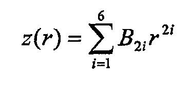
여기서, z는 밀리미터의 광축 방향의 표면의 위치이고, r은 밀리미터의 광축 방향의 거리, Bk는 r의 k승의 계수이다. 계수 B2 내지 B12의 계수의 값은 각각 1.094507, 0.64448149, 0.064744348, 2.3410448, -12.999302, -6.8309113이다. 디스크의 최적의 층 Lopt의 설계 두께는 0.1mm이다. 디스크(310)는 굴절률 1.6223의 폴리카보네이트로 만들어진다. Here, z is the position of the surface in the optical axis direction of millimeters, r is the distance in the optical axis direction of millimeters, and B k is the coefficient of the k power of r. The values of the coefficients of the coefficients B 2 to B 12 are 1.094507, 0.64448149, 0.064744348, 2.3410448, -12.999302, and -6.8309113, respectively. The optimal thickness of the disk layer Lopt is 0.1 mm. The
표 1에, 이 최적의 100㎛ 두께보다 모두 크거나 작고, 실질적으로 동일 량의 잔여의 더 높은 차수의 파면 수차(광학 경로 차이의 제곱 평균(OPD))가 일어나는 것이 발견되는, 2중 층 디스크용의 커버층 두께 D가 리스트된다. 또한, 대응하는 공역 물체 거리 L이 (포지티브 값은 발산하는 빔이 대물 렌즈에 입사하는 것을 의미한다) 주어질 뿐 아니라 NA가 변한다. In Table 1, a two-layer disc, both larger or smaller than this optimal 100 μm thickness, found to have substantially the same amount of residual higher order wavefront aberration (OPD of the optical path difference) The cover layer thickness D for the dragon is listed. In addition, the corresponding conjugated object distance L (positive value means that a diverging beam is incident on the objective lens), as well as the NA changes.
표 1Table 1
표 1로부터, DAV=100.7마이크론인 반면 최적의 층 깊이는 100마이크론이다. 따라서, Dopt는 0.993DAV이다. From Table 1, D AV = 100.7 microns while the optimal layer depth is 100 microns. Thus, Dopt is 0.993D AV .
예 2Example 2
100㎛ 커버층 두께에 대해 최적화된 도 4의 싱글릿 플라스틱 SFFO 렌즈(405)를 고려하자. Consider the singlet
제2실시형태에 있어서, 405nm 파장에서의 광학 기록을 위한 대물 렌즈(305)는 0.85의 개구 수 NA를 갖는다. 입사동 직경 EP는 1.0mm를 측정한다. 자유 동작 거리(FWD)는 렌즈(405)의 전방 단부와 기록 매체(410) 사이에서 0.15mm이다. In the second embodiment, the
도 4에 나타낸 대물 렌즈는 COC(cylco-olefine_copolymer)로 제조된다. COC의 굴절률은 1.5499이다. 광학 축을 따른 렌즈의 두께는 0.915mm이다. 콜리메이터 렌즈에 면하는 표면(407)의 회전 대칭 비구면 형상은,The objective lens shown in FIG. 4 is made of COC (cylco-olefine_copolymer). The refractive index of COC is 1.5499. The thickness of the lens along the optical axis is 0.915 mm. The rotationally symmetric aspherical shape of the

여기서, z는 밀리미터의 광축 방향의 표면의 위치이고, r은 밀리미터의 광축으로의 거리, r0는 밀리미터의 정규화된 반경, Bk는 r의 k승의 계수이다. 콜리메이터에 면하는 표면에 대한 정규화된 반경 r0=0.5mm이다. 계수 B2 내지 B16의 계수의 값은 각각 0.25, 0.029450632, 0.015158439, -0.30922007, 1.356098, -2.5402456, 2.2389527, -0.7750968이다. 디스크(410)에 면하는 표면(409)은 r0=0.25mm인 동일 식으로 주어진다. B2 내지 B16의 계수의 값은 각각 -0.088581439, 0.081735809, -0.063652986, 0.022340965, 0.00054096427, -0.0033723519, 0.0011206103, -0.00012497701이다. 디스크의 최적의 층 Lopt의 설계 두께는 0.1mm이다. 디스크(310)는 굴절률 1.6223의 폴리카보네이트로 만들어진다. Where z is the position of the surface in the optical axis direction in millimeters, r is the distance to the optical axis in millimeters, r 0 is the normalized radius in millimeters, and B k is the coefficient of the k power of r. The normalized radius r 0 = 0.5 mm for the surface facing the collimator. The values of the coefficients of the coefficients B 2 to B 16 are 0.25, 0.029450632, 0.015158439, -0.30922007, 1.356098, -2.5402456, 2.2389527, and -0.7750968, respectively. The
특성은 표 2에 리스트된다. The properties are listed in Table 2.
표 2TABLE 2
표 2로부터, DAV=101.4마이크론인 반면 최적의 층 깊이는 100㎛이다. 따라서, Dopt는 0.993DAV이다. From Table 2, D AV = 101.4 microns while the optimal layer depth is 100 μm. Thus, Dopt is 0.993D AV .
상기 작업 예는, 2중 층 디스크의 정보층 사이에 주어진 커버층 두께에 대해서, 상부 정보층과 하부 정보층 사이의 평균 거리에 근접하게 놓이지만 이 평균 거리로부터 벗어나서 상부층을 향해 놓인 깊이 Dopt에서 최소 구면 차수를 제공하도록 최적화된 대물 렌즈를 선택함으로써, 최적의 렌즈 설계가 발견될 수 있는 것을 가리킨다. 블루-레이 타입 디스크를 판독하거나 유사한 높은 NA 시스템에서 사용되는 대물 렌즈 설계를 위한 Dopt의 유용한 값은, 이 근접 평균 깊이와 깊이(D1+DAV)/2 사이에 놓인다. The above working example lie close to the average distance between the upper and lower information layers for a given cover layer thickness between the information layers of the double layer disc but at a depth Dopt that deviates from this average distance towards the upper layer. By selecting an objective lens optimized to provide spherical order, it is indicated that an optimal lens design can be found. A useful value of Dopt for objective lens designs used to read Blu-ray type discs or used in similar high NA systems lies between this near average depth and depth (D1 + D AV ) / 2.
본 발명은, 다중 층 디스크를 채용하고, 구면 차수 교정을 요구하는 광학 기록 시스템에 사용될 수 있으며, 2중 층 디스크에만 제한되지 않는다. 그런데, 본 발명은 BD 및 SFFO 배열에 대해서 특별한 유용성을 갖는 것을 알 수 있다. 특히, 본 발명은 높은 NA와 작은 포컬 길이를 갖는 SFFO 대물 렌즈를 갖는 시스템과 연관된다. The present invention can be used in an optical recording system that employs a multi-layer disc and requires spherical order correction, but is not limited to double-layer discs. However, it can be seen that the present invention has particular utility for the BD and SFFO arrangements. In particular, the present invention relates to a system having an SFFO objective lens with a high NA and a small focal length.
대물 렌즈는 단일 소자로 도시되었지만, 하나 이상의 소자로 구성될 수도 있다. 또한, 렌즈는 격자나 위상 구조를 구비할 수 있다. Although the objective lens is shown as a single element, it may be composed of one or more elements. In addition, the lens may have a grating or a phase structure.
Claims (10)
Applications Claiming Priority (2)
| Application Number | Priority Date | Filing Date | Title |
|---|---|---|---|
| EP04100138.9 | 2004-01-19 | ||
| EP04100138 | 2004-01-19 |
Publications (1)
| Publication Number | Publication Date |
|---|---|
| KR20060129267A true KR20060129267A (en) | 2006-12-15 |
Family
ID=34854670
Family Applications (1)
| Application Number | Title | Priority Date | Filing Date |
|---|---|---|---|
| KR1020067014470A Withdrawn KR20060129267A (en) | 2004-01-19 | 2005-01-11 | objective |
Country Status (8)
| Country | Link |
|---|---|
| US (1) | US20080219131A1 (en) |
| EP (1) | EP1709635B1 (en) |
| JP (1) | JP2007519148A (en) |
| KR (1) | KR20060129267A (en) |
| CN (1) | CN100437783C (en) |
| AT (1) | ATE413681T1 (en) |
| DE (1) | DE602005010823D1 (en) |
| WO (1) | WO2005078712A1 (en) |
Families Citing this family (7)
| Publication number | Priority date | Publication date | Assignee | Title |
|---|---|---|---|---|
| JP4420920B2 (en) * | 2006-11-08 | 2010-02-24 | ソニーオプティアーク株式会社 | Optical recording medium driving device and focus-on method |
| US8045426B2 (en) | 2007-06-05 | 2011-10-25 | Panasonic Corporation | Optical head device, and recording and/or reproducing device |
| CN101911192B (en) * | 2008-10-24 | 2013-11-06 | 松下电器产业株式会社 | Optical head, optical disk device, and information processing device |
| US20100118685A1 (en) * | 2008-11-12 | 2010-05-13 | Yoshiaki Komma | Optical recording medium, manufacturing method for optical recording medium, information recording/reproducing method and information recording/reproducing device |
| JP5132607B2 (en) * | 2009-03-03 | 2013-01-30 | 三洋電機株式会社 | Optical pickup device |
| KR101286639B1 (en) * | 2009-09-30 | 2013-07-22 | 도시바삼성스토리지테크놀러지코리아 주식회사 | Access method to optical information media and optical pickup device and optical drive adopting the device |
| JP5306261B2 (en) * | 2010-02-26 | 2013-10-02 | 三菱電機株式会社 | Optical pickup device and optical disk device |
Family Cites Families (8)
| Publication number | Priority date | Publication date | Assignee | Title |
|---|---|---|---|---|
| NL9002841A (en) | 1990-12-21 | 1992-07-16 | Philips Nv | METHOD AND APPARATUS FOR REGISTRATION, READING AND DELETING A MULTI-SPACE REGISTRATION CARRIER, AND REGISTRATION CARRIER SUITABLE FOR THIS METHOD AND APPARATUS. |
| US7286153B1 (en) * | 1991-10-11 | 2007-10-23 | Hitachi, Ltd. | Three-dimensional recording and reproducing apparatus |
| KR100385382B1 (en) * | 1994-08-23 | 2003-05-27 | 코닌클리케 필립스 일렉트로닉스 엔.브이. | Device for scanning information layers of an optical record carrier |
| US5625609A (en) * | 1995-03-13 | 1997-04-29 | International Business Machines Corporation | Multiple data layer optical disk drive system with fixed aberration correction and optimum interlayer spacing |
| US6728179B1 (en) * | 1999-05-10 | 2004-04-27 | Sharp Kabushiki Kaisha | Apparatus and method for optical recording/reproducing information including electrical spherical-aberration correction mechanism having low power consumption |
| CN2453515Y (en) * | 2000-02-07 | 2001-10-10 | 武凉 | DVD optical information reproducing device |
| JP3833448B2 (en) * | 2000-07-05 | 2006-10-11 | 株式会社リコー | Optical pickup method and apparatus, and optical information processing apparatus |
| JP2002163830A (en) * | 2000-11-24 | 2002-06-07 | Toshiba Corp | Optical information processing system using optical aberration and information medium having recording layer protected by transparent layer with uneven thickness |
-
2005
- 2005-01-11 US US10/597,122 patent/US20080219131A1/en not_active Abandoned
- 2005-01-11 AT AT05702275T patent/ATE413681T1/en not_active IP Right Cessation
- 2005-01-11 WO PCT/IB2005/000113 patent/WO2005078712A1/en not_active Ceased
- 2005-01-11 DE DE602005010823T patent/DE602005010823D1/en not_active Expired - Fee Related
- 2005-01-11 CN CNB2005800026956A patent/CN100437783C/en not_active Expired - Fee Related
- 2005-01-11 JP JP2006548473A patent/JP2007519148A/en not_active Withdrawn
- 2005-01-11 KR KR1020067014470A patent/KR20060129267A/en not_active Withdrawn
- 2005-01-11 EP EP05702275A patent/EP1709635B1/en not_active Expired - Lifetime
Also Published As
| Publication number | Publication date |
|---|---|
| DE602005010823D1 (en) | 2008-12-18 |
| ATE413681T1 (en) | 2008-11-15 |
| EP1709635B1 (en) | 2008-11-05 |
| WO2005078712A1 (en) | 2005-08-25 |
| EP1709635A1 (en) | 2006-10-11 |
| JP2007519148A (en) | 2007-07-12 |
| CN100437783C (en) | 2008-11-26 |
| CN1910674A (en) | 2007-02-07 |
| US20080219131A1 (en) | 2008-09-11 |
Similar Documents
| Publication | Publication Date | Title |
|---|---|---|
| US6052237A (en) | Objective lens and scanning device using such an objective lens | |
| US6995886B2 (en) | Optical scanning device | |
| US6192022B1 (en) | Focusing a light beam more than thirty focal depths from the aplanatic point with a plano-convex lens | |
| US5926450A (en) | Device for optically scanning record carriers of different thicknesses | |
| KR20060129267A (en) | objective | |
| US6898024B2 (en) | Optical system for optical pickup employing coma compensating element | |
| US6151174A (en) | Device for optically scanning a record carrier | |
| JP2009170071A (en) | Optical pickup optical system and optical pickup device using the same | |
| KR100805266B1 (en) | Optical head for scanning record carrier | |
| JP2005535063A (en) | Scanning device including an objective lens formed of two kinds of materials | |
| JP2004511875A (en) | Optical scanning device | |
| KR100769959B1 (en) | Optical head and optical scanning device for scanning a record carrier | |
| JP3804984B2 (en) | Optical scanning device for record carrier | |
| EP1475652A1 (en) | Objective lens and scanning device using such an objective lens | |
| KR20050030225A (en) | Scanning device including an objective system formed of a single material | |
| JP2005535066A (en) | Scanning device including objective system with lens protection device | |
| KR20050074514A (en) | Optical scanning device | |
| KR20050022007A (en) | Optical scanning device including a tilt tolerant objective system | |
| HK1051085B (en) | Optical pickup with spherical aberration correction | |
| HK1017756A (en) | Objective lens and scanning device using such an objective lens |
Legal Events
| Date | Code | Title | Description |
|---|---|---|---|
| PA0105 | International application |
St.27 status event code: A-0-1-A10-A15-nap-PA0105 |
|
| PG1501 | Laying open of application |
St.27 status event code: A-1-1-Q10-Q12-nap-PG1501 |
|
| PC1203 | Withdrawal of no request for examination |
St.27 status event code: N-1-6-B10-B12-nap-PC1203 |
|
| WITN | Application deemed withdrawn, e.g. because no request for examination was filed or no examination fee was paid | ||
| P22-X000 | Classification modified |
St.27 status event code: A-2-2-P10-P22-nap-X000 |
|
| R18-X000 | Changes to party contact information recorded |
St.27 status event code: A-3-3-R10-R18-oth-X000 |
|
| PN2301 | Change of applicant |
St.27 status event code: A-3-3-R10-R13-asn-PN2301 St.27 status event code: A-3-3-R10-R11-asn-PN2301 |
|
| R18-X000 | Changes to party contact information recorded |
St.27 status event code: A-3-3-R10-R18-oth-X000 |
|
| R18-X000 | Changes to party contact information recorded |
St.27 status event code: A-3-3-R10-R18-oth-X000 |
|
| R18-X000 | Changes to party contact information recorded |
St.27 status event code: A-3-3-R10-R18-oth-X000 |
|
| R18 | Changes to party contact information recorded |
Free format text: ST27 STATUS EVENT CODE: A-3-3-R10-R18-OTH-X000 (AS PROVIDED BY THE NATIONAL OFFICE) |
|
| R18-X000 | Changes to party contact information recorded |
St.27 status event code: A-3-3-R10-R18-oth-X000 |