KR20060082359A - Optical pickup - Google Patents
Optical pickup Download PDFInfo
- Publication number
- KR20060082359A KR20060082359A KR1020050003043A KR20050003043A KR20060082359A KR 20060082359 A KR20060082359 A KR 20060082359A KR 1020050003043 A KR1020050003043 A KR 1020050003043A KR 20050003043 A KR20050003043 A KR 20050003043A KR 20060082359 A KR20060082359 A KR 20060082359A
- Authority
- KR
- South Korea
- Prior art keywords
- light
- incident
- wedge plate
- beam splitter
- disk
- Prior art date
- Legal status (The legal status is an assumption and is not a legal conclusion. Google has not performed a legal analysis and makes no representation as to the accuracy of the status listed.)
- Ceased
Links
Images
Classifications
-
- B—PERFORMING OPERATIONS; TRANSPORTING
- B01—PHYSICAL OR CHEMICAL PROCESSES OR APPARATUS IN GENERAL
- B01L—CHEMICAL OR PHYSICAL LABORATORY APPARATUS FOR GENERAL USE
- B01L3/00—Containers or dishes for laboratory use, e.g. laboratory glassware; Droppers
- B01L3/50—Containers for the purpose of retaining a material to be analysed, e.g. test tubes
- B01L3/508—Rigid containers without fluid transport within
- B01L3/5082—Test tubes per se
-
- B—PERFORMING OPERATIONS; TRANSPORTING
- B01—PHYSICAL OR CHEMICAL PROCESSES OR APPARATUS IN GENERAL
- B01L—CHEMICAL OR PHYSICAL LABORATORY APPARATUS FOR GENERAL USE
- B01L2300/00—Additional constructional details
- B01L2300/02—Identification, exchange or storage of information
- B01L2300/025—Displaying results or values with integrated means
- B01L2300/028—Graduation
Landscapes
- Health & Medical Sciences (AREA)
- Chemical & Material Sciences (AREA)
- Analytical Chemistry (AREA)
- General Health & Medical Sciences (AREA)
- Hematology (AREA)
- Clinical Laboratory Science (AREA)
- Chemical Kinetics & Catalysis (AREA)
- Optical Head (AREA)
Abstract
본 발명은 광 픽업 장치에 관한 것으로, 종래의 고가의 큐빅 프리즘(Cubic prism) 대신에 웨지 플레이트(Wedge plate)를 적용함과 더불어, 두 개의 광원을 모니터할 수 있는 공용 모니터 수광부가 설치된 광학계를 구성함으로써, 광픽업의 가격 경쟁력을 증가시킬 수 있는 우수한 효과가 있다. BACKGROUND OF THE INVENTION 1. Field of the Invention The present invention relates to an optical pick-up apparatus, and applies a wedge plate instead of a conventional cubic prism, and constitutes an optical system provided with a common monitor light receiving unit capable of monitoring two light sources. By doing so, there is an excellent effect that can increase the price competitiveness of the optical pickup.
광픽업, 광학계, 웨지플레이트, 광원, 프리즘Optical pickup, optical system, wedge plate, light source, prism
Description
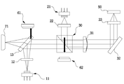
도 1은 종래의 광픽업 장치를 구성하는 광학계를 개략적으로 나타낸 도면1 is a view schematically showing an optical system constituting a conventional optical pickup device
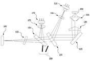
도 2는 본 발명의 제 1 실시예에 따른 광 픽업 장치의 광학계를 계략적으로 나타낸 구성도2 is a configuration diagram schematically showing an optical system of the optical pickup apparatus according to the first embodiment of the present invention.
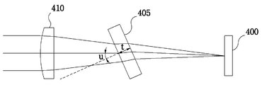
도 3은 일반적으로 발산되는 광경로에 틸트된 플레이트가 존재할 경우, 수차를 설명하기 위한 개념도3 is a conceptual diagram illustrating aberration when a tilted plate exists in a generally emitted light path
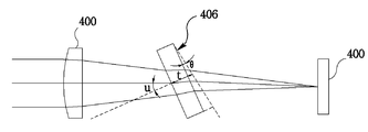
도 4는 본 발명에 따라 사용된 웨지 플레이트(Wedge plate)로 수차를 줄일 수 있는 방법을 설명하기 위한 개념도4 is a conceptual diagram illustrating a method of reducing aberration with a wedge plate used according to the present invention.
도 5는 본 발명의 제 2 실시예에 따른 광 픽업 장치의 광학계를 계략적으로 나타낸 구성도5 is a configuration diagram schematically illustrating an optical system of an optical pickup apparatus according to a second exemplary embodiment of the present invention.
도 6a와 6b는 본 발명에 따라 모니터 수광부로 광원의 광이 입사되는 상태를 도시한 개념도6A and 6B are conceptual views illustrating a state in which light from a light source is incident on a monitor light receiving unit according to the present invention.
도 7은 본 발명에 따라 사용된 웨지 플레이트(Wedge plate)와 제 1 광원과의 관계를 설명하는 개념도7 is a conceptual diagram illustrating a relationship between a wedge plate and a first light source used according to the present invention.
<도면의 주요부분에 대한 부호의 설명><Description of the symbols for the main parts of the drawings>
100,170 : 광원 115,175 : 그레이팅 소자100,170 light source 115,175 grating element
120,121 : 웨지 플레이트(Wedge plate) 125 : 미러120,121: wedge plate 125: mirror
130,410 : 콜리메이터 렌즈 135 : 대물렌즈130,410 collimator lens 135: objective lens
150 : 빔 스프리터(Beam splitter) 155 : 렌즈150: beam splitter 155: lens
160 : 수광부 250 : 모니터 수광부 160: light receiver 250: monitor light receiver
400 : 광원 400: light source
405 : 틸트된 플레이트(Tilted plate)405: tilted plate
본 발명은 광 픽업 장치에 관한 것으로, 보다 상세하게는 종래의 고가의 큐빅 프리즘(Cubic prism) 대신에 웨지 플레이트(Wedge plate)를 적용함으로써 광픽업 장치의 가격 경쟁력을 확보할 수 있고, 두 개의 광원을 모니터할 수 있는 공용 모니터 수광부가 설치된 광학계를 구성함으로써, 광픽업의 가격 경쟁력을 증가시킬 수 있는 광 픽업 장치에 관한 것이다.The present invention relates to an optical pickup device, and more particularly, by applying a wedge plate instead of the expensive cubic prism, the price competitiveness of the optical pickup device can be secured, and two light sources The present invention relates to an optical pickup apparatus capable of increasing the price competitiveness of an optical pickup by configuring an optical system provided with a common monitor light receiving unit capable of monitoring the optical pickup.
최근, 데이터의 디지털화, 대용량화 등에 의하여 저장 매체가 테이프에서 디스크로 바뀌고 있고, 또한 디스크에 데이터를 저장하는 기록 밀도를 높임으로써 디스크의 저장 용량을 크게 하고 있다. In recent years, the storage medium has been changed from tape to disk due to the digitization of data, the increase in capacity, and the like, and the storage capacity of the disk has been increased by increasing the recording density for storing data on the disk.
따라서, 광원으로 사용되는 레이저 다이오드가 780nm의 파장을 갖는 컴팩트 디스크(CD:Compact Disc)에서, 최근에는 대용량화의 차원에서 650nm, 405nm의 파장에 적합한 디스크들이 개발되고 있다. Therefore, in compact discs (CD), in which a laser diode used as a light source has a wavelength of 780 nm, discs suitable for wavelengths of 650 nm and 405 nm have recently been developed for the purpose of large capacity.
이에 따라, 상기 디스크에 정보를 기록하고 재생하는 광픽업 장치는 하위 호환성의 차원에서 저장 밀도가 다른 디스크들에 동시 적용될 수 있도록 다양하게 개발되고 있다.Accordingly, various optical pickup apparatuses for recording and reproducing information on the disc have been developed so that they can be simultaneously applied to discs having different storage densities in terms of backward compatibility.
그리고, 광 디스크 시장에서는 고배속 기록에 대한 요구가 증대됨과 동시에 광픽업 장치의 가격 축소에 대한 요구도 증대되고 있다.In addition, in the optical disc market, the demand for high speed recording is increasing and the demand for reducing the price of the optical pickup device is also increasing.
도 1은 종래의 광픽업 장치를 구성하는 광학계를 개략적으로 나타낸 도면으로서, 650nm의 광빔과 780nm의 광빔을 각각 발생하기 위하여 분리 설치된 제 1 및 제 2 광원(11, 21)과; 이들 광원들(11, 21)로부터 발생된 광을 디스크 트래킹(Tracking)용 광으로 만드는 그레이팅 소자(12, 22)와; 상기 제 1 광원(11)으로부터 발생된 광은 반사시키고, 입사되는 광의 편광 상태에 따라 투과 또는 반사시키는 하프미러(Half mirror)(13)와; 상기 하프미러(13)와 상기 제 2 광원(21)으로부터 각각 입력되는 광을 투과 또는 반사시키는 프리즘(prism)(30)과; 상기 프리즘(30)을 통과한 광을 일정 방향으로 평행하게 진행시키는 콜리메이터 렌즈(31)와; 상기 콜리메이터 렌즈(31)를 투과하는 광을 반사시키는 미러(32)와; 상기 미러(32)에서 반사된 광을 디스크(50)의 표면상의 한 점에 집광시키는 대물렌즈(33)와; 상기 대물렌즈(33), 미러(32), 콜리메이터 렌즈(31), 프리즘(30) 및 하프미러(13)를 거쳐 입사된 디스크(50)로부터 반사된 반사광을 검출하여 전기적 신호로 변환하는 포토 다이오드(71)와; 상기 하프 미러(13)에서 투과된 제 1 광원(11)의 광을 검출 하여 모니터용 신호를 출력하는 제 1 모니터 포토다이오드(61)과; 상기 프리즘(30)에 투과된 제 2 광원(21)의 광을 검출하여 모니터용 신호를 출력하는 제 2 모니터 포토다이오드(62)로 구성된다. 1 is a view schematically showing an optical system constituting a conventional optical pickup apparatus, comprising: first and
먼저, DVD에 정보를 기록 및 재생시키는 동작에 대해 설명하면, 제 1 광원(11)에서 650nm에 해당하는 광이 발생하고, 이와 같이 발생된 광은 그레이팅(12)에 의해 디스크 트래킹용 광으로 변경되어 하프 미러(13)로 입사된다.First, the operation of recording and reproducing information on the DVD will be described. In the
상기 하프 미러(13)는 제 1 광원(11)으로부터 입사된 일부의 광을 반사하여 프리즘(30)으로 출사시키고, 나머지 광은 투과시켜 모니터 포토다이오드(61)로 출사시킨다.The
그 다음, 상기 프리즘(30)에서 투과되어 콜리메이터 렌즈(31)에 평행광이 되고, 미러(32)에서 반사되어 대물렌즈(33)로 입사된다.Then, the light is transmitted by the
그 후, 상기 대물렌즈(33)에서 집광되어 디스크(50)에 집속된다.Thereafter, the light is collected by the
여기서, 상기 디스크(50)는 DVD이다.Here, the
그리고, 상기 디스크(50)에서 반사된 광은 대물렌즈(33), 미러(32), 콜리메이터 렌즈(31), 프리즘(30)과 하프미러(13)을 통하여 포토다이오드(71)에 입사되고, 상기 포토다이오드(71)는 입사된 광을 전기적 신호로 변환시켜 출력한다.The light reflected from the
또한, CD에 정보를 기록 및 재생시키는 동작은, 제 2 광원(21)에서 780nm에 해당하는 광이 발생하고, 이 광은 그레이팅(12)에 의해 디스크 트래킹용 광으로 변경되어 프리즘(30)으로 입사된다.In addition, in the operation of recording and reproducing information on the CD, light corresponding to 780 nm is generated in the
상기 프리즘(30)는 제 2 광원(21)으로부터 입사된 광의 일부를 반사하여 프 리즘(30)으로 출사되고, 나머지 광은 투과시켜 모니터 포토다이오드(62)로 출사시킨다.The
그리고, 상기 프리즘(30)에서 반사된 광은 콜리메이터 렌즈(31)에서 평행광이 되고, 미러(32)에서 반사되어 대물렌즈(33)로 입사되며, 상기 대물렌즈(33)에서 집광되어 디스크(50)에 집속된다.The light reflected by the
여기서, 상기 디스크(50)는 CD이다.Here, the
그리고, 전술된 DVD의 경우와 동일하게, 상기 디스크(50)에서 반사된 광은 대물렌즈(33), 미러(32), 콜리메이터 렌즈(31), 프리즘(30)과 하프미러(13)을 통하여 포토다이오드(71)에 입사되고, 상기 포토다이오드(71)는 입사된 광을 전기적 신호로 변환시켜 출력한다.As in the case of the above-described DVD, the light reflected from the
이와 같이, 종래 기술에서는 종래의 고가의 큐빅 프리즘(Cubic prism)을 사용함으로써, 광픽업 장치의 가격이 높고, 두 개의 광원을 각각 모니터할 수 있는 두 개의 모니터 수광부가 설치되어 있어 가격면에 불리한 단점이 있다.As described above, in the prior art, the price of the optical pickup device is high by using a conventional expensive cubic prism, and two monitor light receiving units for monitoring two light sources are installed, which is disadvantageous in terms of price. There is this.
본 발명은 상기한 바와 같은 문제점을 해결하기 위하여, 종래의 고가의 큐빅 프리즘(Cubic prism) 대신에 웨지 플레이트를 적용함으로써 광픽업 장치의 가격 경쟁력을 확보할 수 있고, 두 개의 광원을 모니터할 수 있는 공용 모니터 수광부가 설치된 광학계를 구성함으로써, 광픽업의 가격 경쟁력을 증가시킬 수 있는 광 픽업 장치를 제공하는 데 목적이 있다. In order to solve the problems described above, the present invention can secure the price competitiveness of the optical pickup device by applying a wedge plate instead of the expensive cubic prism, and can monitor two light sources. An object of the present invention is to provide an optical pickup device capable of increasing the price competitiveness of an optical pickup by configuring an optical system provided with a common monitor light receiving unit.
상기한 본 발명의 목적들을 달성하기 위한 바람직한 제 1 양태(樣態)는, 제 1과 2 광을 각각 발생하여 출사시키고, 상호 이격되어 있는 제 1 및 2 광원과; A first preferred aspect for achieving the above objects of the present invention comprises: first and second light sources that generate and emit first and second light, respectively, and are spaced apart from each other;
상기 제 1 광원에서 출사된 광을 포함하여 입사되는 광의 일부는 투과시키고 나머지는 반사시키며, 일면에 비해 그 일면의 반대면이 넓은 웨지 플레이트(Wedge plate)와; A wedge plate that transmits a part of the incident light, including the light emitted from the first light source, and reflects the rest of the light, and a surface opposite to one surface thereof is wider than one surface thereof;
상기 제 2 광원에서 출사된 광의 일부를 상기 웨지 플레이트로 반사시키고 나머지는 투과시키며, 입사되는 광의 일부를 반사 또는 투과시키는 빔 스프리터(Beam splitter)와; A beam splitter for reflecting a portion of the light emitted from the second light source to the wedge plate and transmitting the remaining portion, and reflecting or transmitting a portion of the incident light;
상기 웨지 플레이트로부터 입사된 광을 포함하여 입사되는 광을 반사시키는 미러(Morror)와; A mirror configured to reflect incident light including light incident from the wedge plate;
상기 미러에서 반사된 광을 일정 방향으로 평행하게 진행시키는 콜리메이터 렌즈와; A collimator lens for advancing the light reflected from the mirror in parallel in a predetermined direction;
상기 콜리메이터 렌즈를 통한 광을 디스크에 집광시키는 대물렌즈와; An objective lens for condensing light through the collimator lens on a disk;
상기 디스크로부터 반사된 광이 대물렌즈, 콜리메이터 렌즈, 미러, 웨지 플레이트 및 빔 스프리터를 거쳐 검출되면 전기적 신호로 변환하는 수광부와; A light receiving unit converting the light reflected from the disk into an electrical signal when it is detected through an objective lens, a collimator lens, a mirror, a wedge plate, and a beam splitter;
상기 제 1과 2 광원에서 출사된 광을 검출하여 모니터 신호를 출력하는 모니터 수광부를 포함하여 구성된 광 픽업 장치를 포함하여 구성된 광 픽업 장치가 제공된다.There is provided an optical pickup device comprising an optical pickup device configured to include a monitor light receiving unit which detects light emitted from the first and second light sources and outputs a monitor signal.
상기한 본 발명의 목적들을 달성하기 위한 바람직한 제 2 양태(樣態)는, 제 1과 2 광을 각각 발생하여 출사시키고, 상호 이격되어 있는 제 1 및 2 광원과; A second preferred aspect for achieving the above objects of the present invention comprises: first and second light sources which generate and emit first and second light, respectively, and are spaced apart from each other;
상기 제 1 광원에서 출사된 광을 투과시키고, 상기 제 2 광원에서 출사된 광을 반사시키는 웨지 플레이트(Wedge plate)와; A wedge plate for transmitting the light emitted from the first light source and reflecting the light emitted from the second light source;
상기 제 2 광원에서 출사된 광의 일부를 상기 웨지 플레이트로 반사시키고 나머지는 투과시키며, 입사되는 광의 일부를 반사 또는 투과시키는 빔 스프리터(Beam splitter)와; A beam splitter for reflecting a portion of the light emitted from the second light source to the wedge plate and transmitting the remaining portion, and reflecting or transmitting a portion of the incident light;
상기 빔 스프리터에서 반사된 광을 일정 방향으로 평행하게 진행시키는 콜리메이터 렌즈와; A collimator lens configured to propagate the light reflected by the beam splitter in parallel in a predetermined direction;
상기 콜리메이터 렌즈를 통한 광을 포함하여 입사되는 광을 반사시키는 미러(Morror)와; A mirror configured to reflect incident light including light through the collimator lens;
상기 미러에서 반사된 광을 디스크에 집광시키는 대물렌즈와; An objective lens for condensing the light reflected by the mirror onto a disk;
상기 디스크로부터 반사된 광이 대물렌즈, 미러, 콜리메이터 렌즈와 빔 스프리터를 거쳐 검출되면 전기적 신호로 변환하는 수광부와; A light receiving unit converting the light reflected from the disk into an electrical signal when it is detected through an objective lens, a mirror, a collimator lens and a beam splitter;
상기 제 1과 2 광원에서 출사된 광을 검출하여 모니터 신호를 출력하는 모니터 수광부를 포함하여 구성된 광 픽업 장치가 제공된다.
There is provided an optical pickup device including a monitor light receiving unit that detects light emitted from the first and second light sources and outputs a monitor signal.
이하, 첨부된 도면을 참조하여 본 발명의 바람직한 실시예를 설명하면 다음과 같다. Hereinafter, exemplary embodiments of the present invention will be described with reference to the accompanying drawings.
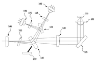
도 2는 본 발명의 제 1 실시예에 따른 광 픽업 장치의 광학계를 계략적으로 나타낸 구성도로서, 제 1과 2 광을 각각 발생하여 출사시키고, 상호 이격되어 있는 제 1 및 2 광원(110,170)과; 상기 제 1 광원(110)에서 출사된 광을 포함하여 입사되는 광의 일부는 투과시키고 나머지는 반사시키며, 일면에 비해 그 일면의 반대면이 넓은 웨지 플레이트(Wedge plate)(120)와; 상기 제 2 광원(170)에서 출사된 광의 일부를 상기 웨지 플레이트(120)로 반사시키고 나머지는 투과시키며, 입사되는 광의 일부를 반사 또는 투과시키는 빔 스프리터(Beam splitter)(150)와; 상기 웨지 플레이트(120)로부터 입사된 광을 포함하여 입사되는 광을 반사시키는 미러(Morror)(125)와; 상기 미러(125)에서 반사된 광을 일정 방향으로 평행하게 진행시키는 콜리메이터 렌즈(130)와; 상기 콜리메이터 렌즈(130)를 통한 광을 디스크(200)에 집광시키는 대물렌즈(135)와; 상기 디스크(200)로부터 반사된 광이 대물렌즈(135), 콜리메이터 렌즈(130), 미러(125), 웨지 플레이트(120) 및 빔 스프리터(150)를 거쳐 검출되면 전기적 신호로 변환하는 수광부(160)와; 상기 제 1과 2 광원(110,170)에서 출사되어 상기 웨지 플레이트(120)와 빔 스프리터(150)에서 투과된 광을 검출하여 모니터 신호를 출력하는 모니터 수광부(250)를 포함하여 구성된다.FIG. 2 is a schematic diagram illustrating an optical system of an optical pickup apparatus according to a first exemplary embodiment of the present invention. First and second lights are generated and emitted, respectively, and are spaced apart from each other. and; A
여기서, 상기 수광부(160)와 빔 스프리터(150) 사이에는 빔 스프리터(150)에서 투과된 광을 집광시키는 렌즈(155)가 더 구비된 것이 바람직하다.Here, it is preferable that a
그리고, 상기 제 1 광원(110)과 웨지 플레이트(120) 사이 및 상기 제 2 광원(170)과 빔 스프리터(150) 사이에는 제 1과 2 광원(110,170)에서 출사된 광을 디스크 트래킹(Tracking)용 광으로 만드는 그레이팅 소자(115,175)가 더 구비된 것이 바람직하다.Further, the light emitted from the first and second
또한, 상기 제 1과 2 광원(110,170)은 레이저 다이오드이고, 상기 수광부(160) 및 모니터 수광부(250)는 포토 다이오드인 것이 바람직하다.In addition, the first and second
더불어, 상기 디스크(200)는 선택적으로 절환되어서 그 기록면이 대물렌즈 초점에 일치되는 두 개의 디스크 중 하나인 것이 바람직하다.In addition, it is preferable that the
그리고, 상기 두 개의 디스크는 CD와 DVD, CD와 BD(Blu-ray Disc) 및 DVD와 BD 중 어느 하나인 것이 바람직하다.Preferably, the two discs are any one of a CD and a DVD, a CD and a BD (Blu-ray Disc), and a DVD and a BD.
또한, 상기 도 2의 디스크(200)는 CD, DVD, BD(Blu-ray Disc) 중 어느 하나인 것이 바람직하다.In addition, the
이렇게 구성된 본 발명의 제 1 실시예는 제 1과 2 광원(110,170)에서 출사된 광은 웨지 플레이트(120) 및 빔 스프리터(150)에서 각각 반사되고, 미러(125)에서 반사되어 콜리메이터 렌즈(130)를 통하여 평행광으로 되고, 대물렌즈(135)에서 집광되어 디스크(200)로 집속된다.In the first embodiment of the present invention configured as described above, the light emitted from the first and second
그리고, 상기 디스크(200)에서 반사된 광은 대물렌즈(135), 콜리메이터 렌즈(130), 웨지 플레이트(120), 빔 스프리터(150)와 렌즈(155)을 거쳐 수광부(160)로 입사되어 전기적 신호로 변환된다.The light reflected from the
한편, 상기 제 1과 2 광원(110,170)에서 출사된 광은 상기 웨지 플레이트(120)와 빔 스프리터(150)에서 일부는 반사되고, 나머지 광은 투과되어 모니터 수광부(250)로 입사되며, 상기 모니터 수광부(250)는 상기 입사된 광을 검출하여 모니터 신호를 출력한다.Meanwhile, the light emitted from the first and second
도 3은 일반적으로 발산되는 광경로에 틸트된 플레이트가 존재할 경우, 수차를 설명하기 위한 개념도로서, 일반적으로 광원(400)에서 콜리메이터 렌즈(410)로 발산되는 광경로에 틸트된 플레이트(Tilted plate)(405)가 있으면, 비점수차(Astigmatism)와 코마수차(Coma)가 발생하고, 이 수차는 하기의 수학식 1과 2를 통해 계산할 수 있다.3 is a conceptual diagram illustrating aberration when a tilted plate exists in a light path that is generally emitted, and is generally a tilted plate in the light path that is emitted from the

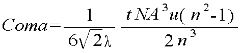
상기의 수학식 1과 2에서 알 수 있는 바와 같이, 틸트된 플레이트가 발산광 구간에 배치될 때, 수자는 플레이트의 두께, 틸트된 각도와 콜리메이터 렌즈의 NA에 비례한다.As can be seen in Equations 1 and 2 above, when the tilted plate is disposed in the divergent light section, the number is proportional to the thickness of the plate, the tilted angle and the NA of the collimator lens.
이 때, 사각판 형상의 플레이트 두께(t)는 1.5 ㎜이고, NA는 0.12이고, 틸트 각도(u)는 30°, 광의 파장(λ)는 660㎚인 경우 수차를 계산하면, At this time, when the plate thickness t of the square plate shape is 1.5 mm, NA is 0.12, the tilt angle u is 30 °, and the wavelength λ of the light is 660 nm, the aberration is calculated.
비점수차(Astigmatism) = 0.341λrms이고, 코마수차(Coma) = 0.0601λrms이다.Astigmatism = 0.341 lambda rms and coma = 0.0601 lambda rms.
그러므로, 전체 파면수차는 대략 0.383λrms이다.Therefore, the total wave front aberration is approximately 0.383 lambda rms.
통상, 광픽업 장치의 전체 파면수차는 0.07λrms이하를 요구하므로, 이 사각판 형상의 플레이트를 사용할 경우, 수차는 너무 커서 광 디스크의 신호를 읽거나 신호를 기록했을 때, 지터(Jitter)가 커지고 RF 신호의 열화가 심해져 광픽업 장치로 성능을 발휘할 수 없게된다.In general, since the total wave front aberration of the optical pickup device requires 0.07 lambda rms or less, when using this rectangular plate-shaped plate, the aberration is so large that the jitter becomes large when the signal of the optical disc is read or recorded. The deterioration of the RF signal is severe and the performance of the optical pickup device may not be achieved.
도 4는 본 발명에 따라 사용된 웨지 플레이트(Wedge plate)로 수차를 줄일 수 있는 방법을 설명하기 위한 개념도로서, 도 3의 사각판 형상의 플레이트 면에서 웨지각(Wedge angle)(θ)만큼 확장된 웨지 플레이트(Wedge plate)(406)를 발산되는 광 경로에 위치시키면, 비점수차와 코마수차가 감소하여 수차가 최소화된다.FIG. 4 is a conceptual view illustrating a method of reducing aberration with a wedge plate used according to the present invention, and extends by a wedge angle θ at the plate-shaped plate surface of FIG. 3. By placing the
이 틸트된 웨지 플레이트는 도 3과 같은 사각판 형상의 플레이트와 형상이 상당히 다르므로, 수학식 1과 2를 사용하여 비점수차와 코마수차를 계산할 수 없다.Since the tilted wedge plate is significantly different from the rectangular plate shape plate as shown in FIG. 3, astigmatism and coma aberration cannot be calculated using Equations 1 and 2. FIG.
그러므로, 본 발명은 플레이트 두께(t)(중심축의 두께)는 1.5 ㎜이고, NA는 0.12이고, 틸트 각도(u)는 30°, 광의 파장(λ)는 660㎚인 조건으로, 광학 설계 프로그램인 Code Ⅴ에서 수차를 계산하였는데, 비점수차는 0.0033λrms로 계산되었고, 코마수차는 0.0132λrms로 계산되었다.Therefore, the present invention is an optical design program under the condition that the plate thickness t (thickness of the central axis) is 1.5 mm, NA is 0.12, the tilt angle u is 30 °, and the wavelength of light λ is 660 nm. The aberration was calculated in Code V. The astigmatism was calculated as 0.0033λrms, and the coma aberration was calculated as 0.0132λrms.
즉, 이 수차량을 웨지각이 없는 도 3의 경우와 비교하면, 비점수차가 100분의 1 이하로 감소되었고, 코마수차도 5분의 1 이하로 감소됨을 알 수 있다.That is, comparing the aberration amount with the case of FIG. 3 without the wedge angle, it can be seen that the astigmatism is reduced to less than one hundredth, and the coma aberration is also reduced to less than one fifth.
이러한 이유는, 웨지 플레이트는 사지탈(Sagittal) 광과, 사지탈(Sagittal) 광에 수직한 탄젠셜(Tangential) 광의 경로차를 최소화시킬 수 있어 수차가 감소된다.For this reason, the wedge plate can minimize the path difference between the sagittal light and the tangential light perpendicular to the sagittal light, thereby reducing the aberration.
따라서, 전술된 웨지 플레이트는 전체 파면수자가 0.0172λrms로 광픽업 장치의 파면 수차 요구 수준인 0.07λrms이하가 되어 광픽업 장치에 적용할 수 있게 된다. Therefore, the wedge plate described above can be applied to the optical pickup apparatus because the total wavefront number is 0.0172 lambda rms, which is equal to or less than 0.07 lambda rms, which is the wavefront aberration required level of the optical pickup apparatus.
도 5는 본 발명의 제 2 실시예에 따른 광 픽업 장치의 광학계를 계략적으로 나타낸 구성도로서, 제 1과 2 광을 각각 발생하여 출사시키고, 상호 이격되어 있는 제 1 및 2 광원(110,170)과; 상기 제 1 광원(110)에서 출사된 광을 투과시키고, 상기 제 2 광원(170)에서 출사된 광을 반사시키는 웨지 플레이트(Wedge plate)(121)와; 상기 제 2 광원(170)에서 출사된 광의 일부를 상기 웨지 플레이트(120)로 반사시키고 나머지는 투과시키며, 입사되는 광의 일부를 반사 또는 투과시키는 빔 스프리터(Beam splitter)(150)와; 상기 빔 스프리터(150)에서 반사된 광을 일정 방향으로 평행하게 진행시키는 콜리메이터 렌즈(130)와; 상기 콜리메이터 렌즈(130)를 통한 광을 포함하여 입사되는 광을 반사시키는 미러(Morror)(125)와; 상기 미러(125)에서 반사된 광을 디스크(200)에 집광시키는 대물렌즈(135)와; 상기 디스크(200)로부터 반사된 광이 대물렌즈(135), 미러(125), 콜리메이터 렌즈(130)와 빔 스프리터(150)를 거쳐 검출되면 전기적 신호로 변환하는 수광부(160)와; 상기 제 1과 2 광원(110,170)에서 출사되어 상기 빔 스프리터(150)에서 투과된 광을 검출하여 모니터 신호를 출력하는 모니터 수광부(250)를 포함하여 구성된다.FIG. 5 is a schematic diagram illustrating an optical system of an optical pickup apparatus according to a second exemplary embodiment of the present invention. First and second lights are generated and emitted, respectively, and are spaced apart from each other. and; A wedge plate (121) for transmitting the light emitted from the first light source (110) and reflecting the light emitted from the second light source (170); A beam splitter (150) for reflecting a part of the light emitted from the second light source (170) to the wedge plate (120) and transmitting the rest, and reflecting or transmitting a part of the incident light; A
상기와 같이 구성된 본 발명의 제 2 실시예는 제 1과 2 광원(110,170)에서 출사된 광은 웨지 플레이트(121) 투과 및 반사되고, 빔 스프리터(150)에서 반사되어 콜리메이터 렌즈(130)를 통하여 평행광으로 되고, 미러(125)에서 반사되어서 대물렌즈(135)에서 집광되어 디스크(200)로 집속된다.According to the second embodiment of the present invention configured as described above, the light emitted from the first and second
또한, 상기 디스크(200)에서 반사된 광은 대물렌즈(135), 미러(125), 콜리메 이터 렌즈(130), 빔 스프리터(150)와 렌즈(155)을 거쳐 수광부(160)로 입사되어 전기적 신호로 변환된다.In addition, the light reflected from the
더불어, 상기 제 1과 2 광원(110,170)에서 출사된 광은 상기 빔 스프리터(150)에서 일부가 투과되어 모니터 수광부(250)로 입사되며, 상기 모니터 수광부(250)는 상기 입사된 광을 검출하여 모니터 신호를 출력한다.In addition, the light emitted from the first and second
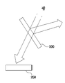
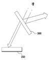
도 6a와 6b는 본 발명에 따라 모니터 수광부로 광원의 광이 입사되는 상태를 도시한 개념도로서, 먼저, 본 발명의 제 1 실시예인 도 2에서 웨지 플레이트와 빔 스프리터, 본 발명의 제 2 실시예인 도 5에서 빔 스프리터는 도 6a와 같이 '500'으로 도시하였는데, 이 웨지 플레이트와 빔 스프리터는 광원에서 출사된 광의 일부는 반사시키고, 나머지 광을 투과시켜 모니터 수광부(250)로 입사시킨다.6A and 6B are conceptual views illustrating a state in which light of a light source is incident on a monitor light receiving unit according to the present invention. First, the wedge plate and the beam splitter in FIG. 2, which is the first embodiment of the present invention, are the second embodiment of the present invention. In FIG. 5, the beam splitter is shown as '500' as shown in FIG. 6A. The wedge plate and the beam splitter reflect some of the light emitted from the light source and transmit the remaining light to enter the
그러나, 도 6b와 같이, 광원에서 출사된 광의 일부가 웨지 플레이트 또는 빔 스프리터(500)에 입사되지 않도록 위치시키고, 입사된 광원의 광이 반사되도록 웨지 플레이트 또는 빔 스프리터(500)를 구성하면, 광원에서 출사된 광의 대부분은 반사되고, 미량의 광(전체의 광에서 약 1% 이내)은 웨지 플레이트 또는 빔 스프리터(500)에 조사되지 않고, 직접 모니터 수광부(250)로 입사된다.However, as shown in FIG. 6B, when a part of the light emitted from the light source is positioned so as not to be incident on the wedge plate or the
즉, 도 2에서 웨지 플레이트(120)는 제 1 광원(110)에서 출사된 광의 일부가 모니터 수광부(250)에 입사되도록 위치시키고, 나머지 광이 입사되어서 반사되어 미러(125)로 출사되도록 구성한다.That is, in FIG. 2, the
그리고, 도 2의 빔 스프리터(150)는 제 2 광원(170)에서 출사된 광의 일부가 모니터 수광부(250)에 입사되도록 위치시키고, 나머지 광이 입사되어서 반사되어 웨지 플레이트(120)로 출사되도록 구성한다.And, the
또한, 도 5의 빔 스프리터(150)는 제 1과 2 광원(110,170)에서 출사된 광의 일부가 모니터 수광부(250)에 입사되도록 위치시키고, 나머지 광이 입사되어서 반사되어 콜리메이터 렌즈(130)로 출사되도록 구성하는 것이다.In addition, the
더불어, 상기 웨지 플레이트와 빔 스프리터는 입사되는 광의 편광 상태에 따라 투과할 수 있도록 구성하여, 디스크로부터 반사된 광을 수광부로 입사시킬 수 있는 것이다.In addition, the wedge plate and the beam splitter may be configured to transmit according to the polarization state of the incident light, thereby allowing the light reflected from the disk to enter the light receiving unit.
그러므로, 도 6b의 경우, 광원에서 출사되어 입사된 광을 전부 디스크로 보낼 수 있게 되어 광 효율이 높아져, 고배속 기록 및 재생할 수 있게 된다.Therefore, in the case of Fig. 6B, all the light emitted from the light source and sent to the disk can be sent to the disk, so that the light efficiency is high, and high speed recording and reproduction can be performed.
그리고, 상기 디스크에서 반사된 광은 투과되어 수광부로 입사된다.Then, the light reflected from the disk is transmitted and incident to the light receiving portion.
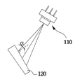
도 7은 본 발명에 따라 사용된 웨지 플레이트(Wedge plate)와 제 1 광원과의 관계를 설명하는 개념도로서, 제 1 광원(110)에서 출사된 광이 입사각α(10°〈α〈45°)로 입사되도록, 웨지 플레이트(120)를 설치하는 것이 바람직하다. FIG. 7 is a conceptual diagram illustrating a relationship between a wedge plate and a first light source used according to the present invention, wherein light emitted from the first
이상 상술한 바와 같이, 본 발명은 종래의 고가의 큐빅 프리즘(Cubic prism) 대신에 웨지 플레이트(Wedge plate)를 적용함으로써 광픽업 장치의 가격 경쟁력을 확보할 수 있고, 두 개의 광원을 모니터할 수 있는 공용 모니터 수광부가 설치된 광학계를 구성함으로써, 광픽업의 가격 경쟁력을 증가시킬 수 있는 우수한 효과가 있다. As described above, the present invention can secure the price competitiveness of the optical pickup device by applying a wedge plate instead of the expensive cubic prism, and can monitor two light sources. By configuring the optical system provided with the common monitor receiving unit, there is an excellent effect that can increase the price competitiveness of the optical pickup.
본 발명은 구체적인 예에 대해서만 상세히 설명되었지만 본 발명의 기술사상 범위 내에서 다양한 변형 및 수정이 가능함은 당업자에게 있어서 명백한 것이며, 이러한 변형 및 수정이 첨부된 특허청구범위에 속함은 당연한 것이다.
Although the invention has been described in detail only with respect to specific examples, it will be apparent to those skilled in the art that various modifications and variations are possible within the spirit of the invention, and such modifications and variations belong to the appended claims.
Claims (8)
Priority Applications (1)
| Application Number | Priority Date | Filing Date | Title |
|---|---|---|---|
| KR1020050003043A KR20060082359A (en) | 2005-01-12 | 2005-01-12 | Optical pickup |
Applications Claiming Priority (1)
| Application Number | Priority Date | Filing Date | Title |
|---|---|---|---|
| KR1020050003043A KR20060082359A (en) | 2005-01-12 | 2005-01-12 | Optical pickup |
Publications (1)
| Publication Number | Publication Date |
|---|---|
| KR20060082359A true KR20060082359A (en) | 2006-07-18 |
Family
ID=37173089
Family Applications (1)
| Application Number | Title | Priority Date | Filing Date |
|---|---|---|---|
| KR1020050003043A Ceased KR20060082359A (en) | 2005-01-12 | 2005-01-12 | Optical pickup |
Country Status (1)
| Country | Link |
|---|---|
| KR (1) | KR20060082359A (en) |
Cited By (1)
| Publication number | Priority date | Publication date | Assignee | Title |
|---|---|---|---|---|
| KR101329244B1 (en) * | 2012-02-24 | 2013-11-14 | (주)아이엠 | Optical pickup device |
-
2005
- 2005-01-12 KR KR1020050003043A patent/KR20060082359A/en not_active Ceased
Cited By (1)
| Publication number | Priority date | Publication date | Assignee | Title |
|---|---|---|---|---|
| KR101329244B1 (en) * | 2012-02-24 | 2013-11-14 | (주)아이엠 | Optical pickup device |
Similar Documents
| Publication | Publication Date | Title |
|---|---|---|
| US6552974B1 (en) | Compatible optical pickup | |
| KR100243134B1 (en) | Optical pickup device for recording reproduction | |
| KR100449402B1 (en) | Optical pickup device | |
| US5784354A (en) | Optical pickup device | |
| JP3677200B2 (en) | Optical pickup device | |
| US7180837B2 (en) | Optical pickup including an optical modulator, and an optical apparatus comprising the optical pickup | |
| KR100294886B1 (en) | Compatible optical pickup device | |
| JPH10308031A (en) | Optical pickup device | |
| KR100699809B1 (en) | Optical pickup device | |
| JP3896171B2 (en) | Optical pickup and optical disk apparatus | |
| KR100803592B1 (en) | Compatible optical pickups and optical recording and / or reproducing apparatus employing the same | |
| KR100737859B1 (en) | Optical recorder / playback device | |
| KR20060082359A (en) | Optical pickup | |
| JP3772851B2 (en) | Optical pickup device and optical disk device | |
| KR100289719B1 (en) | Compatibel optical pickup apparatus | |
| KR100493041B1 (en) | Recordable optical pickup | |
| JP3455675B2 (en) | Optical pickup device | |
| JP2006268899A (en) | Optical pickup device | |
| KR100281880B1 (en) | Compatible optical pickup | |
| KR100215455B1 (en) | DVD / CD combined optical pickup system for detecting focus errors | |
| KR100683888B1 (en) | Optical pickup | |
| KR100602700B1 (en) | Optical pickup | |
| KR100430270B1 (en) | Tilt detecting method in an optical pickup | |
| KR100600587B1 (en) | Optical pickup | |
| JP4117302B2 (en) | Optical pickup and optical disk apparatus |
Legal Events
| Date | Code | Title | Description |
|---|---|---|---|
| A201 | Request for examination | ||
| PA0109 | Patent application |
Patent event code: PA01091R01D Comment text: Patent Application Patent event date: 20050112 |
|
| PA0201 | Request for examination | ||
| E902 | Notification of reason for refusal | ||
| PE0902 | Notice of grounds for rejection |
Comment text: Notification of reason for refusal Patent event date: 20060516 Patent event code: PE09021S01D |
|
| PG1501 | Laying open of application | ||
| E601 | Decision to refuse application | ||
| PE0601 | Decision on rejection of patent |
Patent event date: 20060724 Comment text: Decision to Refuse Application Patent event code: PE06012S01D Patent event date: 20060516 Comment text: Notification of reason for refusal Patent event code: PE06011S01I |