KR200460161Y1 - Catheter with a improved head part - Google Patents
Catheter with a improved head part Download PDFInfo
- Publication number
- KR200460161Y1 KR200460161Y1 KR2020100000077U KR20100000077U KR200460161Y1 KR 200460161 Y1 KR200460161 Y1 KR 200460161Y1 KR 2020100000077 U KR2020100000077 U KR 2020100000077U KR 20100000077 U KR20100000077 U KR 20100000077U KR 200460161 Y1 KR200460161 Y1 KR 200460161Y1
- Authority
- KR
- South Korea
- Prior art keywords
- catheter
- container
- head portion
- stopper
- coupled
- Prior art date
- Legal status (The legal status is an assumption and is not a legal conclusion. Google has not performed a legal analysis and makes no representation as to the accuracy of the status listed.)
- Expired - Lifetime
Links
Images



Classifications
-
- A—HUMAN NECESSITIES
- A61—MEDICAL OR VETERINARY SCIENCE; HYGIENE
- A61M—DEVICES FOR INTRODUCING MEDIA INTO, OR ONTO, THE BODY; DEVICES FOR TRANSDUCING BODY MEDIA OR FOR TAKING MEDIA FROM THE BODY; DEVICES FOR PRODUCING OR ENDING SLEEP OR STUPOR
- A61M25/00—Catheters; Hollow probes
- A61M25/002—Packages specially adapted therefor ; catheter kit packages
-
- A—HUMAN NECESSITIES
- A61—MEDICAL OR VETERINARY SCIENCE; HYGIENE
- A61M—DEVICES FOR INTRODUCING MEDIA INTO, OR ONTO, THE BODY; DEVICES FOR TRANSDUCING BODY MEDIA OR FOR TAKING MEDIA FROM THE BODY; DEVICES FOR PRODUCING OR ENDING SLEEP OR STUPOR
- A61M2210/00—Anatomical parts of the body
- A61M2210/10—Trunk
- A61M2210/1078—Urinary tract
- A61M2210/1089—Urethra
Landscapes
- Health & Medical Sciences (AREA)
- Life Sciences & Earth Sciences (AREA)
- Biophysics (AREA)
- Pulmonology (AREA)
- Engineering & Computer Science (AREA)
- Anesthesiology (AREA)
- Biomedical Technology (AREA)
- Heart & Thoracic Surgery (AREA)
- Hematology (AREA)
- Animal Behavior & Ethology (AREA)
- General Health & Medical Sciences (AREA)
- Public Health (AREA)
- Veterinary Medicine (AREA)
- Media Introduction/Drainage Providing Device (AREA)
- External Artificial Organs (AREA)
- Infusion, Injection, And Reservoir Apparatuses (AREA)
Abstract
본 고안은 헤드부가 개선된 요도 삽입용 카테타에 관한 것으로, 카테타의 상단이 마개로부터 이탈될 때 수용관에 끼여 인출이 어렵게 되는 것을 방지하기 위한 헤드부가 개선된 요도 삽입용 카테타를 제공함에 그 목적이 있다.
본 고안을 적용하면, 마개의 결합돌부에 상단이 결합된 카테타가 뜻하지 않게 보관용기의 내부에서 분리되는 경우가 발생하더라도 카테타 상단의 헤드부 외주연에 걸림돌기가 형성되어 용기의 내부로 깊숙하게 낙하하는 것을 방지할 수 있으므로 쉽게 결합돌부를 이용하여 카테타를 보관용기로 부터 꺼낼 수 있다는 장점이 있다.The present invention relates to a catheter for urethral insertion with improved head portion, and to provide a urethral catheter for improved head portion to prevent the difficulty of withdrawal is caught in the receiving tube when the top of the catheter is separated from the stopper. have.
When the present invention is applied, even if the catheter coupled to the upper end of the stopper is unexpectedly separated from the inside of the storage container, a protrusion is formed on the outer periphery of the head of the catheter and falls deeply into the inside of the container. Since it is possible to prevent the catheter can be easily removed from the storage container by using the engaging protrusion.
Description
본 고안은 헤드부가 개선된 요도 삽입용 카테타에 관한 것으로, 보다 상세하게는 카테타의 상단이 마개로부터 이탈될 때 수용관에 끼여 인출이 어렵게 되는 것을 방지하기 위한 헤드부가 개선된 요도 삽입용 카테타에 관한 것이다.The present invention relates to a catheter for urethral insertion with an improved head portion, and more particularly to a catheter for improved urethral insertion of the head portion to prevent the extraction is difficult to get stuck in the receiving tube when the top of the catheter is separated from the stopper. will be.
주지된 바와 같이, 카테타는 플렉서블(Flexible)한 미세관으로써 요도에 삽입되는 관이다. 이때 요도에 삽입되는 카테타의 경우는 배뇨장애를 갖는 환자의 요도에 일시적으로 삽입되어 소변을 외부로 배출시키는 기능을 수행하는 바, 상황에 따라 신체로부터 이탈시켜서 약물로 소독하거나, 신체 외부에 보관하는 경우가 있다.As is well known, a catheter is a tube inserted into the urethra as a flexible microtubule. In this case, the catheter inserted into the urethra is temporarily inserted into the urethra of the patient with urination disorder and discharges urine to the outside. There is a case.
따라서, 이러한 카테타는 소독이나 보관을 위한 별도의 보관용기가 개발되었다.Therefore, such a catheter has been developed a separate storage container for disinfection or storage.
도 1은 종래의 실시예에 따른 요도 삽입용 카테타 보관용기의 외형을 도시한 사시도이고, 도 2는 종래의 실시예에 따른 요도 삽입용 카테타 보관용기의 보관상태를 도시한 사시도이며, 도 3은 종래의 실시예에 따른 요도 삽입용 카테타의 용기 수용상태를 도시한 요부 확대 측단면도이다.1 is a perspective view showing the appearance of the urethral insertion catheter storage container according to a conventional embodiment, Figure 2 is a perspective view showing a storage state of the urethral insertion catheter storage container according to a conventional embodiment, Figure 3 It is a main portion enlarged side cross-sectional view showing the container receiving state of the urethral insertion catheter according to the conventional embodiment.
이를 참조하면, 종래의 실시예에 따른 요도 삽입용 카테타 보관용기(2)는 장형의 관형태로 이루어지고 일단이 폐쇄되어 내부에 카테타(30)를 보관할 수 있는 용기부(4)가 구성되는 바, 그 용기부(4)는 중앙의 자바라 관(10)을 기준으로 상부용기(6)와 하부용기(8)로 각각 구성된다. 자바라 관(10)은 상부용기(6)와 하부용기(8)를 접어서 휴대나 보관하기 용이하게 하기 위한 수단이다.Referring to this, the urethra insertion
상기 상부용기(6)의 상단 외주연 소정부에는 상부용기(6)의 외주연에 결합된 상부리브(12)가 구성되고, 그 상부리브(12)는 일측에 수직방향으로 결합공(14)이 형성되어 행거(20)의 일단이 결합되게 구성된다.The upper outer periphery of the upper portion of the
상기 행거(20)는 그 일단에 상기 결합공(14)으로부터의 이탈을 방지하기 위한 돌기(22)가 형성되어져 있고, 그 중앙부가 절곡되어 약물 지지대(미도시)의 고리(미도시)에 걸리도록 하는 걸림부(24)가 형성되고, 그 걸림부(24)의 타단에는 삽입부(26)가 연장되게 구성된다.The
상기 하부용기(8)의 하단 외주연 소정부에는 하부용기(8)의 외주연에 결합된 하부리브(16)가 구성되고, 그 하부리브(16)는 일측에 수직방향으로 삽입공(18)이 형성되어 상기 삽입부(26)의 단부가 결합되게 구성된다.The lower outer periphery of the
상부용기(6)의 단부는 개방되어져 있고, 그 개방된 입구를 통해 카테타(30)를 내부에 수용할 수 있으며, 개방된 단부를 밀폐시키기 위해 상부용기(6)에 결합되는 마개(28)가 구성되어져 있다. 마개(28)는 그 외주연에 다각면(28a)이 형성된다. 또한, 마개(28)는 그 하면에 하방으로 돌출된 결합돌부(39)가 구성되어 그 결합돌부(39)를 카테타(30)의 상단에 끼움으로써, 차후 카테타(30)를 용기부(4)로부터 쉽게 꺼낼 수 있게 구성된다.The end of the
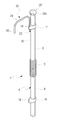
미설명부호 40 은 카테타(30)의 헤드부(40)를 나타낸 것이며, 그 헤드부(40)는 상부가 개방된 개방구(42)가 구비되며, 내부에는 결합력을 높이기 위한 돌기(42)가 일정간격으로 형성되어져 있다. 상기 상부용기(6)의 상단 외주연에는 일정간격으로 상기 마개(28)와 결합되기 위한 나사부(6a)가 형성되어져 있다.
종래의 실시예에 따른 요도 삽입용 카테타 보관용기(2)는 카테타(30)의 소독 필요시 상기 용기부(4)의 내부에 소독약물을 주입한 후, 카테타(30)를 그 용기부(4)에 삽입하고 마개(28)로 밀폐하여 카테타(30)를 보관하거나 소독할 수 있다.The urethra insertion
그러나, 종래의 실시예에 따른 요도 삽입용 카테타 보관용기(2)는 상기 용기부(4)에 보관된 카테타(30)를 인출하려고 할 때, 마개(28)를 개방하면 마개(28)의 하단에 구성된 결합돌부(39)에 카테타(30)가 끼워진 상태로 마개(28)와 함께 카테타(30)가 인출되게 되는 데, 이때 마개(28)의 결합돌부(39)와 카테타(30)는 단순한 끼움결합 상태이므로 이들이 분리되는 경우가 빈번하였다.However, when the
일단, 마개(28)와 카테타(30)가 분리되게 되면, 오염의 우려 때문에 손가락이나 다른 물체로 카테타 보관용기(2)내에 수용된 카테타(30)를 집어낼 수가 없었으므로 카테타 보관용기(2)의 내부에 카테타(30)와 함께 수용된 소독약액을 모두 버리는 방법을 통해 카테타(30)를 외부로 꺼내야 되므로, 결국 고가의 소독약액이 낭비된다는 문제점이 있었다.Once the
또한, 상기 상부용기(6)와 하부용기(8)의 직경이 너무 넓기 때문에 카테타(30)를 소독하기 위한 소독약액을 더 많은 양 주입해야 한다는 문제가 있었다. 특히, 소독약액은 수차례 새롭게 용기내로 주입해야 하므로 비용 부담이 컸다.In addition, since the diameter of the
따라서, 상기한 문제점을 해결하기 위해 본 출원인은 도 4에 도시된 보관용기를 개발하였다.Therefore, in order to solve the above problems, the applicant has developed the storage container shown in FIG.
도 4는 종래의 다른 실시예에 따른 요도 삽입용 카테타 보관용기의 외형을 도시한 사시도이다.Figure 4 is a perspective view showing the appearance of the urethral insertion catheter storage container according to another embodiment of the prior art.
이를 참조하면, 종래의 다른 실시예에 따른 요도 삽입용 카테타 보관용기(100)도 역시 그 용기부(102)의 중앙에 신축적으로 절곡되는 자바라관(108)이 구비되고, 그 자바라관(108)의 양단에 연장되는 소직경의 수용관(110,112)이 구비되어져 있다.Referring to this, the urethra insertion
소직경의 수용관(110,112)은 기존의 용기부 직경에 비해 협소하게 구성되므로 용기부(102)에 채워져야 하는 약물의 양을 줄일 수 있다.Small diameter receiving pipe (110, 112) is narrower than the existing diameter of the container portion can reduce the amount of drug to be filled in the container portion (102).
상기 수용관(110,112)의 양단에 각각 연장되며, 상기 수용관(110, 112)의 직경보다 더 큰 직경을 갖는 상부용기(104) 및 하부용기(106)가 구성되는 바, 상부용기(104) 및 하부용기(106)의 길이는 상기 수용관(110,112)의 길이보다 작다.The
상기 상부용기(104)와 수용관(110)의 연결부위에는 카테타(138)의 헤드부(도 3참조: 40)가 걸리게 된 걸림턱(114)이 구비되어져 있다.The connection portion of the
종래 고안에 구성된 마개(132)는 사용자가 손쉽게 개폐할 수 있도록 그 외주연(134)을 따라 일정간격으로 돌기(136)가 형성되어져 있다.The
또한, 종래의 다른 실시예에 따른 요도 삽입용 카테타 보관용기(100)도 병실에 구비된 약액통 행거(미도시)에 걸리거나, 벽의 옷걸이, 못 등에 걸릴 수 있는 행거(120)가 구성되는 바, 그 행거(120)는 요도 삽입용 카테타 보관용기(100)가 기울어지지 않게 하며, 손쉽게 상부 용기(104)에 대해 하부용기(106)가 결합될 수 있게 구성된다.In addition, the urethra insertion
이를 위해, 상기 상부용기(104)의 외주연에는 그 외주연을 감싸게 리브(122)가 결합되어져 있으며, 리브(122)의 외주연 소정부로부터 횡방향으로 연장된 지지대(124)가 형성되고, 상기 지지대(124)의 단부에는 수용관(112)이 결합되는 홀더(126)가 구성된다.To this end, a
상기 홀더(126)는 하부용기(106)의 외주면에 형성된 복수개의 유동방지돌기(106a)에 결합될 수 있도록 그 외주연이 일부 절개된 절개부(126a)가 형성되어져 있다.The
따라서, 사용자가 상기 상부용기(104)를 한손으로 파지한 상태에서 다른 손으로 하부용기(106)를 접게 되면 자바라관(108) 부분이 접히면서 상기 하부용기(106)가 상부용기(104)와 평행하게 이동되고 사용자는 하부용기(106)의 외주면에 형성된 유동방지돌기(106a)사이에 상기 홀더(126)의 절개부(126a)에 억지끼움 방식으로 끼워넣어 간단하게 결합시킬 수 있다.Therefore, when the user folds the
이 경우, 종래 고안처럼 리브를 삽입단에 맞춰서 조절할 필요가 없으며, 별도의 하부 리브를 용기에 끼울 필요가 없으므로 편의성이 높고 경제적이다.In this case, there is no need to adjust the ribs to the insertion end as in the conventional design, and there is no need to insert a separate lower rib into the container, which is convenient and economical.
한편, 상기 지지대(124)는 그 중앙에 연장핀(128)이 형성되고, 그 연장핀(128)에 대해 유동 가능하게 결합된 걸림고리(130)가 구성된다. 걸림고리(130)가 못이나 기타 행거고리(도 2참조: 32)에 걸리게 되는 바, 그 걸림고리(130)는 지지대(124)의 중앙에 형성된 연장핀(128)에 유동 가능하게 결합되므로 요도 삽입용 카테타 보관용기(100)가 기울어지지 않게 매달릴 수 있게 하며, 상기 걸림고리(130)가 연장핀(128)에 대해 유동 가능하므로 외부 충격에도 쉽게 행거고리(32)로부터 이탈되지 않고 안정적으로 매달릴 수 있다.On the other hand, the
그러나, 상기 상부용기(104)와 수용관(110)의 연결부위에는 카테타(138)의 헤드부(도 3참조: 40)가 걸리도록 하는 걸림턱(114)이 형성되어져 있지만, 이는 실제로 테이퍼진 형태로 구성된 헤드부(40)가 소직경으로 이루어진 상기 수용관(110)에 더욱 끼여 인출이 더 어렵게 된다는 문제가 있었다.However, although the
본 고안은 상기한 종래 기술의 사정을 감안하여 이루어진 것으로, 카테타의 상단이 마개로부터 이탈될 때 수용관에 끼여 인출이 어렵게 되는 것을 방지하기 위한 헤드부가 개선된 요도 삽입용 카테타를 제공함에 그 목적이 있다.The present invention has been made in view of the above-described prior art, and an object of the present invention is to provide a catheter for urethral insertion with an improved head portion for preventing the upper end of the catheter from being plugged into the receiving tube and making it difficult to withdraw. have.
상기한 목적을 달성하기 위해, 본 고안의 바람직한 실시예에 따르면 소독약물을 수용하며, 상부 용기와 그 상부용기의 하단에 연통되는 소직경의 수용관과, 그 상부 용기와 수용관의 연결부위가 경사지게 구성된 걸림턱으로 이루어진 보관용기에 함께 수용되는 요도 삽입용 카테타에 있어서, 보관용기에 마련된 마개의 결합돌부와 결합되도록 상단이 개방된 헤드부와; 상기 헤드부의 하단에 연통되게 결합되고, 요도에 삽입되는 삽입관으로 이루어지되, 상기 헤드부는 그 하단에 상기 상부 용기와 수용관의 사이에 형성된 걸림턱에 걸리도록 수용관의 직경보다 더 큰 걸림돌기가 형성된 것을 특징으로 하는 헤드부가 개선된 요도 삽입용 카테타가 제공된다.In order to achieve the above object, according to a preferred embodiment of the present invention to accommodate the disinfectant, the small diameter receiving tube communicated to the lower end of the upper container and the upper container, and the connection portion of the upper container and the receiving tube An urethral insertion catheter accommodated together with a storage container including an inclined locking jaw, comprising: a head portion of which an upper end is opened to be coupled to a coupling protrusion of a stopper provided in the storage container; Is coupled to communicate with the lower end of the head portion, it is made of an insertion tube inserted into the urethra, the head portion is larger than the diameter of the receiving tube so as to catch the locking jaw formed between the upper container and the receiving tube at its lower end There is provided a catheter for urethra insertion with an improved head portion.
바람직하게, 상기 헤드부는 그 내부 통로가 상기 마개의 결합돌부가 쉽게 결합되도록 상광하협 형태로 테이퍼진 것을 특징으로 하는 헤드부가 개선된 요도 삽입용 카테타가 제공된다.Preferably, the head portion is provided with a catheter for improved urethra insertion, characterized in that the inner passage is tapered in the form of a light beam narrow so that the engaging protrusion of the stopper is easily coupled.
바람직하게, 상기 결합돌부의 길이와 헤드부의 길이를 합한 값은 상기 상부용기의 길이보다 더 크게 구성된 것을 특징으로 하는 헤드부가 개선된 요도 삽입용 카테타가 제공된다. Preferably, the sum of the length of the coupling protrusion and the length of the head portion is provided with an improved urethral catheter for the head portion, characterized in that configured larger than the length of the upper container.
본 고안에 따른 헤드부가 개선된 요도 삽입용 카테타는 마개의 결합돌부에 상단이 결합된 카테타가 뜻하지 않게 보관용기의 내부에서 분리되는 경우가 발생하더라도 카테타 상단의 헤드부 외주연에 걸림돌기가 형성되어 이 걸림돌기에 의해 보관용기의 내부로 카테타가 깊숙하게 낙하하는 것을 방지할 수 있어 결합돌부를 이용하여 카테타를 보관용기의 외부로 간편하게 꺼낼 수 있다는 장점이 있다.The urethra insertion catheter with improved head portion according to the present invention has a protrusion formed on the outer periphery of the head portion of the catheter even if the catheter coupled to the top of the stopper is unintentionally separated from the inside of the storage container. It is possible to prevent the catheter from falling deeply into the inside of the storage container by the locking protrusion, so that the catheter can be easily taken out of the storage container by using the engaging protrusion.
도 1은 종래의 실시예에 따른 요도 삽입용 카테타 보관용기의 외형을 도시한 사시도,
도 2는 종래의 실시예에 따른 요도 삽입용 카테타 보관용기의 보관상태를 도시한 사시도,
도 3은 종래의 실시예에 따른 요도 삽입용 카테타의 용기 수용상태를 도시한 요부 확대 측단면도,
도 4는 종래의 다른 실시예에 따른 요도 삽입용 카테타 보관용기의 외형을 도시한 사시도,
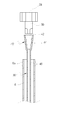
도 5는 본 고안의 일실시예에 따른 헤드부가 개선된 요도 삽입용 카테타의 용기 수용상태를 도시한 요부 확대 측단면도이다.1 is a perspective view showing the outer appearance of the catheter storage container for insertion of urethra according to a conventional embodiment,
Figure 2 is a perspective view showing a storage state of the catheter storage container for insertion of urethra according to a conventional embodiment,
Figure 3 is an enlarged side cross-sectional view showing the main portion of the container receiving state of the urethra insertion catheter according to a conventional embodiment,
Figure 4 is a perspective view showing the appearance of the urethral insertion catheter storage container according to another embodiment of the prior art,
Figure 5 is an enlarged side cross-sectional view showing the main portion of the container receiving state of the urethra insertion catheter improved head portion according to an embodiment of the present invention.
이하, 본 고안에 대해 도면을 참조하여 상세하게 설명한다.Hereinafter, the present invention will be described in detail with reference to the drawings.
도 5는 본 고안의 일실시예에 따른 헤드부가 개선된 요도 삽입용 카테타의 용기 수용상태를 도시한 요부 확대 측단면도이다.Figure 5 is an enlarged side cross-sectional view showing the main portion of the container receiving state of the urethra insertion catheter improved head portion according to an embodiment of the present invention.
이를 참조하면, 본 고안의 일실시예에 따른 헤드부가 개선된 요도 삽입용 카테타(138)는 카테타의 상단이 마개로부터 이탈될 때 수용관에 끼여 인출이 어렵게 되는 것을 방지하기 위한 카테타이다.Referring to this, the
앞서 설명했듯이, 소독약물을 수용하며 상부 용기(104)와 그 상부용기(104)의 하단에 연통되는 소직경의 수용관(110)과, 상기 상부 용기(104)와 수용관(110)의 연결부위가 경사지게 구성된 걸림턱(114)으로 이루어진 보관용기(100)에 대해, 카테타(30)의 헤드부(40)가 도 3에 도시된 바와 같이 상광하협의 형태로 테이퍼지게 구성되면, 헤드부(40)가 마개(28)의 결합돌부(39)로부터 뜻하지 않게 이탈되게 될 때 헤드부(40)의 하단 외주연이 소직경의 수용관(110)에 끼이게 되어 더욱 인출이 어렵게 된다.As described above, the small
따라서, 본 고안의 일실시예에 따른 헤드부가 개선된 요도 삽입용 카테타(138)는 헤드부(140)의 끼임을 방지하기 위한 구조의 개선을 이루었다.Therefore, the
먼저, 본 고안의 일실시예에 따른 헤드부가 개선된 요도 삽입용 카테타(138)는 보관용기(100)에 마련된 마개(132)의 결합돌부(139)와 결합되도록 상단에 개방구(142)가 형성된 헤드부(140)가 제공된다.First, the
또한, 상기 헤드부(140)의 하단에는 그 헤드부(140)와 연통되게 결합되고, 요도에 삽입되는 삽입관(148)으로 구성되는 바, 상기 헤드부(140)는 그 하단에 상기 상부 용기(104)와 수용관(110)의 사이에 형성된 걸림턱(114)에 걸리도록 수용관(110)의 직경보다 더 큰 걸림돌기(146)가 형성되어져 있다.In addition, the lower end of the
이때, 상기 헤드부(140)는 그 재질이 상기 삽입관(148)과 같은 연질의 폴리우레탄이며, 상기 헤드부(140)는 그 내부 통로가 상기 마개(132)의 결합돌부(139)가 쉽게 결합되도록 상광하협 형태로 테이퍼지게 구성된다.At this time, the
또, 상기 헤드부(140)는 그 내부둘레에 일정간격으로 결합돌기(144)가 형성되어 상기 결합돌부(139)와의 결합력을 높일 수 있게 구성된다.In addition, the
즉, 본 고안의 일실시예에 따른 헤드부가 개선된 요도 삽입용 카테타(138)의 헤드부(140)는 그 내부 통로가 상기 마개(132)의 결합돌부(139)에 대해 쉽게 결합될 수 있도록 상광하협의 형태로 테이퍼져 있지만, 그 외면의 경우 내부 구조와 동일하게 상광하협의 형태로 테이퍼지게 된다면, 마개(132)로부터 카테타(138)가 뜻하지 않게 이탈되는 경우, 상기 헤드부(140)의 하단은 종래 도 3에 도시된 바와 같이 협소한 수용관(110)내에 끼이게 된다.That is, the
따라서, 본 고안의 일실시예에 따른 헤드부가 개선된 요도 삽입용 카테타(138)의 헤드부(140)는 그 외면이 내부 구조와 동일하게 상광하협의 형태로 테이퍼지면서, 그 하단부는 외측으로 상기 수용관(110)의 직경보다 더 큰 직경을 갖는 걸림돌기(146)를 구성함으로써, 마개(132)로부터 카테타(138)가 뜻하지 않게 이탈되는 경우가 발생하더라도 상기 걸림돌기(146)가 수용관(110)의 입구부분에 걸려서 쉽게 마개(132)의 결합돌부(139) 등을 이용하여 보관용기(100)의 외부로 인출할 수 있게 된다.Accordingly, the
이때, 본 고안은 바람직하게는 상기 결합돌부(139)의 길이와 헤드부(140)의 길이를 합한 값이 상기 상부용기(104)의 길이보다 더 커야한다. 그래야만, 마개(132)로부터 카테타(138)가 뜻하지 않게 이탈되는 경우라고 할지라도 수용관(110)의 입구부분에 걸린 헤드부(140)를 마개(132)의 결합돌부(139)를 이용하여 용이하게 인출할 수 있기 때문이다.At this time, the present invention preferably the sum of the length of the
아울러, 본 고안은 상기 걸림돌기(146)의 구성만으로 한정하지 아니하고 보관용기(100)의 수용관(110) 입구부분에서 카테타(138)가 걸쳐질 수 있도록 상기 걸림돌기(146)가 형성된 위치의 외부직경을 상기 수용관(110)의 내부직경보다 크게하는 경우 동일한 효과를 구현할 수 있게 된다.In addition, the present invention is not limited to the configuration of the locking
한편, 본 고안의 실시예에 따른 헤드부가 개선된 요도 삽입용 카테타는 단지 상기한 실시예에 한정되는 것이 아니라 그 기술적 요지를 이탈하지 않는 범위내에서 다양한 변경이 가능하다.On the other hand, the urethra insertion catheter with improved head portion according to an embodiment of the present invention is not limited to the above embodiment, but various modifications can be made within the scope without departing from the technical gist.
100:요도 삽입용 카테타 보관용기, 102:용기부,
104:상부용기, 106:하부용기,
108:자바라관, 110,112:수용관,
114:걸림턱, 120:행거,
124:지지대, 126:홀더,
128:연장핀, 130:걸림고리,
132:마개, 138:카테타,
139:결합돌부, 140:헤드부,
146:걸림돌기.100: urethral insertion catheter storage container, 102: container part,
104: upper container, 106: lower container,
108: Jabara Pavilion, 110, 112: Receiving Pavilion,
114: Jam jaw, 120: Hanger,
124: support, 126: holder,
128: extension pin, 130: hook,
132: stopper, 138: catheter,
139: coupling protrusion, 140: head,
146: jamming.
Claims (3)
보관용기에 마련된 마개의 결합돌부와 결합되도록 상단이 개방된 헤드부와;
상기 헤드부의 하단에 연통되게 결합되고, 요도에 삽입되는 삽입관으로 이루어지되,
상기 헤드부는 그 하단에 상기 상부 용기와 수용관의 사이에 형성된 걸림턱에 걸리도록 수용관의 직경보다 더 큰 직경을 갖는 걸림돌기가 형성되며;
상기 결합돌부의 길이와 헤드부의 길이를 합한 값은 상기 상부용기의 길이보다 더 크게 구성된 것을 특징으로 하는 헤드부가 개선된 요도 삽입용 카테타.A urethral catheter for accommodating disinfectant and contained together in a storage container consisting of a small diameter receiving tube communicating with an upper container and a lower end of the upper container, and a locking jaw formed at a connection between the upper container and the receiving tube inclined. To
A head portion of which an upper end is opened to be coupled to a coupling protrusion of a stopper provided in a storage container;
Is coupled to communicate with the bottom of the head portion, made of an insertion tube inserted into the urethra,
The head portion is formed at a lower end thereof with a locking protrusion having a diameter larger than that of the receiving tube so as to be caught by a locking jaw formed between the upper container and the receiving tube;
The combined length of the coupling protrusion and the length of the head portion is the urethral catheter for improved head portion, characterized in that configured larger than the length of the upper container.
Priority Applications (2)
| Application Number | Priority Date | Filing Date | Title |
|---|---|---|---|
| KR2020100000077U KR200460161Y1 (en) | 2010-01-06 | 2010-01-06 | Catheter with a improved head part |
| JP2010040194A JP4987996B2 (en) | 2010-01-06 | 2010-02-25 | Urethral catheter with improved head |
Applications Claiming Priority (1)
| Application Number | Priority Date | Filing Date | Title |
|---|---|---|---|
| KR2020100000077U KR200460161Y1 (en) | 2010-01-06 | 2010-01-06 | Catheter with a improved head part |
Publications (2)
| Publication Number | Publication Date |
|---|---|
| KR20110007008U KR20110007008U (en) | 2011-07-13 |
| KR200460161Y1 true KR200460161Y1 (en) | 2012-05-04 |
Family
ID=44456161
Family Applications (1)
| Application Number | Title | Priority Date | Filing Date |
|---|---|---|---|
| KR2020100000077U Expired - Lifetime KR200460161Y1 (en) | 2010-01-06 | 2010-01-06 | Catheter with a improved head part |
Country Status (2)
| Country | Link |
|---|---|
| JP (1) | JP4987996B2 (en) |
| KR (1) | KR200460161Y1 (en) |
Families Citing this family (8)
| Publication number | Priority date | Publication date | Assignee | Title |
|---|---|---|---|---|
| DK2609956T3 (en) | 2011-12-27 | 2019-06-03 | Dentsply Ih Ab | TEMPORARY FOLDABLE CATEGORY AGREEMENT AND THEREOF |
| USD775522S1 (en) | 2011-12-27 | 2017-01-03 | Dentsply Ih Ab | Catheter package |
| DK2609955T3 (en) | 2011-12-27 | 2020-08-17 | Dentsply Ih Ab | CATHETER COLLECTION WITH LUCKY OPENING |
| EP2823845B1 (en) | 2013-07-12 | 2019-02-27 | Curan Medical B.V. | Male urinary catheter package |
| JPWO2015075841A1 (en) * | 2013-11-25 | 2017-03-16 | 独立行政法人国立病院機構 | Intermittent self urinary catheter |
| US9827063B1 (en) | 2016-07-06 | 2017-11-28 | Medtronic Vascular, Inc. | Hybrid sealed tray for long catheter delivery systems |
| JP6535126B2 (en) * | 2018-06-26 | 2019-06-26 | 独立行政法人国立病院機構 | Intermittent self-feeding catheter |
| US12383700B2 (en) | 2019-06-13 | 2025-08-12 | Hollister Incorporated | Reusable urinary catheter products |
Citations (1)
| Publication number | Priority date | Publication date | Assignee | Title |
|---|---|---|---|---|
| US20090149837A1 (en) * | 2001-06-29 | 2009-06-11 | Coloplast A/S | Catheter Assembly |
Family Cites Families (2)
| Publication number | Priority date | Publication date | Assignee | Title |
|---|---|---|---|---|
| JPH0334170Y2 (en) * | 1988-09-07 | 1991-07-19 | ||
| DK172941B1 (en) * | 1996-09-18 | 1999-10-11 | Coloplast As | A urinary catheter assembly |
-
2010
- 2010-01-06 KR KR2020100000077U patent/KR200460161Y1/en not_active Expired - Lifetime
- 2010-02-25 JP JP2010040194A patent/JP4987996B2/en not_active Expired - Fee Related
Patent Citations (1)
| Publication number | Priority date | Publication date | Assignee | Title |
|---|---|---|---|---|
| US20090149837A1 (en) * | 2001-06-29 | 2009-06-11 | Coloplast A/S | Catheter Assembly |
Also Published As
| Publication number | Publication date |
|---|---|
| JP4987996B2 (en) | 2012-08-01 |
| JP2011139882A (en) | 2011-07-21 |
| KR20110007008U (en) | 2011-07-13 |
Similar Documents
| Publication | Publication Date | Title |
|---|---|---|
| KR200460161Y1 (en) | Catheter with a improved head part | |
| AU2024204895B2 (en) | Package for medical device for ergonomic device removal | |
| ES2703757T3 (en) | A plugging device for a medical access connector | |
| JP2021518182A5 (en) | ||
| US20100252469A1 (en) | Container For Medical Devices | |
| JP2019501741A (en) | Disinfection cap for IV needleless connector | |
| MX2011010308A (en) | DEVICE FOR MICROBIAL WASHING. | |
| ES2657683T3 (en) | Assembly comprising an adapter for coupling with a medical container and a blister pack | |
| ES2656291T3 (en) | Emptying device, assembly, and method for emptying suction bags | |
| KR200456838Y1 (en) | Catheter carrying case | |
| CN104053463A (en) | Outer end fittings for permanent conduits suitable for isolating fluid flow | |
| KR200470650Y1 (en) | Toothpaste dispenser with rack fortootbrush | |
| KR20050033598A (en) | Cotton swab holder | |
| CN217960931U (en) | Guide wire catheter collecting and cleaning device | |
| US20100030169A1 (en) | Catheter system | |
| JPS6130664Y2 (en) | ||
| CN209075666U (en) | Fluid exchange pipe and pouch irrigation and drainage device | |
| KR101823641B1 (en) | Disposable babies bottle with milk powder containing structure | |
| KR20190084184A (en) | Apparatus for keeping swab | |
| CN216496821U (en) | Infusion tubular product storage device of clinical usefulness | |
| KR100877722B1 (en) | Structure of new chopsticks | |
| ES2394083T3 (en) | Container for collecting organic liquids | |
| KR20090024023A (en) | Medical Feed Tube Assembly | |
| KR200369991Y1 (en) | Structure of Inner Tube Twine of Syringe for Portable Vaginal Cleaner | |
| JP2022023264A (en) | Nasal discharge sucker |
Legal Events
| Date | Code | Title | Description |
|---|---|---|---|
| A201 | Request for examination | ||
| UA0108 | Application for utility model registration |
St.27 status event code: A-0-1-A10-A12-nap-UA0108 |
|
| UA0201 | Request for examination |
St.27 status event code: A-1-2-D10-D11-exm-UA0201 |
|
| UN2301 | Change of applicant |
St.27 status event code: A-3-3-R10-R13-asn-UN2301 St.27 status event code: A-3-3-R10-R11-asn-UN2301 |
|
| UG1501 | Laying open of application |
St.27 status event code: A-1-1-Q10-Q12-nap-UG1501 |
|
| E902 | Notification of reason for refusal | ||
| UE0902 | Notice of grounds for rejection |
St.27 status event code: A-1-2-D10-D21-exm-UE0902 |
|
| E13-X000 | Pre-grant limitation requested |
St.27 status event code: A-2-3-E10-E13-lim-X000 |
|
| P11-X000 | Amendment of application requested |
St.27 status event code: A-2-2-P10-P11-nap-X000 |
|
| P13-X000 | Application amended |
St.27 status event code: A-2-2-P10-P13-nap-X000 |
|
| E701 | Decision to grant or registration of patent right | ||
| UE0701 | Decision of registration |
St.27 status event code: A-1-2-D10-D22-exm-UE0701 |
|
| REGI | Registration of establishment | ||
| UR0701 | Registration of establishment |
St.27 status event code: A-2-4-F10-F11-exm-UR0701 |
|
| UR1002 | Payment of registration fee |
St.27 status event code: A-2-2-U10-U11-oth-UR1002 Fee payment year number: 1 |
|
| UG1601 | Publication of registration |
St.27 status event code: A-4-4-Q10-Q13-nap-UG1601 |
|
| R18-X000 | Changes to party contact information recorded |
St.27 status event code: A-5-5-R10-R18-oth-X000 |
|
| R18-X000 | Changes to party contact information recorded |
St.27 status event code: A-5-5-R10-R18-oth-X000 |
|
| FPAY | Annual fee payment |
Payment date: 20150414 Year of fee payment: 4 |
|
| UR1001 | Payment of annual fee |
St.27 status event code: A-4-4-U10-U11-oth-UR1001 Fee payment year number: 4 |
|
| FPAY | Annual fee payment |
Payment date: 20160324 Year of fee payment: 5 |
|
| UR1001 | Payment of annual fee |
St.27 status event code: A-4-4-U10-U11-oth-UR1001 Fee payment year number: 5 |
|
| FPAY | Annual fee payment |
Payment date: 20170324 Year of fee payment: 6 |
|
| UR1001 | Payment of annual fee |
St.27 status event code: A-4-4-U10-U11-oth-UR1001 Fee payment year number: 6 |
|
| P22-X000 | Classification modified |
St.27 status event code: A-4-4-P10-P22-nap-X000 |
|
| FPAY | Annual fee payment |
Payment date: 20180407 Year of fee payment: 7 |
|
| UR1001 | Payment of annual fee |
St.27 status event code: A-4-4-U10-U11-oth-UR1001 Fee payment year number: 7 |
|
| FPAY | Annual fee payment |
Payment date: 20190408 Year of fee payment: 8 |
|
| UR1001 | Payment of annual fee |
St.27 status event code: A-4-4-U10-U11-oth-UR1001 Fee payment year number: 8 |
|
| UC1801 | Expiration of term |
St.27 status event code: N-4-6-H10-H14-oth-UC1801 Not in force date: 20200107 Ip right cessation event data comment text: Termination Category : EXPIRATION_OF_DURATION |