KR102819521B1 - Autonomous driving vehicle with foldable accelerator pedal apparatus and foldable brake pedal apparatus - Google Patents
Autonomous driving vehicle with foldable accelerator pedal apparatus and foldable brake pedal apparatus Download PDFInfo
- Publication number
- KR102819521B1 KR102819521B1 KR1020190146872A KR20190146872A KR102819521B1 KR 102819521 B1 KR102819521 B1 KR 102819521B1 KR 1020190146872 A KR1020190146872 A KR 1020190146872A KR 20190146872 A KR20190146872 A KR 20190146872A KR 102819521 B1 KR102819521 B1 KR 102819521B1
- Authority
- KR
- South Korea
- Prior art keywords
- foldable
- pedal device
- driver
- accelerator pedal
- brake pedal
- Prior art date
- Legal status (The legal status is an assumption and is not a legal conclusion. Google has not performed a legal analysis and makes no representation as to the accuracy of the status listed.)
- Active
Links
Images




Classifications
-
- G—PHYSICS
- G05—CONTROLLING; REGULATING
- G05G—CONTROL DEVICES OR SYSTEMS INSOFAR AS CHARACTERISED BY MECHANICAL FEATURES ONLY
- G05G1/00—Controlling members, e.g. knobs or handles; Assemblies or arrangements thereof; Indicating position of controlling members
- G05G1/30—Controlling members actuated by foot
-
- B—PERFORMING OPERATIONS; TRANSPORTING
- B60—VEHICLES IN GENERAL
- B60K—ARRANGEMENT OR MOUNTING OF PROPULSION UNITS OR OF TRANSMISSIONS IN VEHICLES; ARRANGEMENT OR MOUNTING OF PLURAL DIVERSE PRIME-MOVERS IN VEHICLES; AUXILIARY DRIVES FOR VEHICLES; INSTRUMENTATION OR DASHBOARDS FOR VEHICLES; ARRANGEMENTS IN CONNECTION WITH COOLING, AIR INTAKE, GAS EXHAUST OR FUEL SUPPLY OF PROPULSION UNITS IN VEHICLES
- B60K26/00—Arrangement or mounting of propulsion-unit control devices in vehicles
- B60K26/02—Arrangement or mounting of propulsion-unit control devices in vehicles of initiating means or elements
-
- B—PERFORMING OPERATIONS; TRANSPORTING
- B60—VEHICLES IN GENERAL
- B60T—VEHICLE BRAKE CONTROL SYSTEMS OR PARTS THEREOF; BRAKE CONTROL SYSTEMS OR PARTS THEREOF, IN GENERAL; ARRANGEMENT OF BRAKING ELEMENTS ON VEHICLES IN GENERAL; PORTABLE DEVICES FOR PREVENTING UNWANTED MOVEMENT OF VEHICLES; VEHICLE MODIFICATIONS TO FACILITATE COOLING OF BRAKES
- B60T7/00—Brake-action initiating means
- B60T7/02—Brake-action initiating means for personal initiation
- B60T7/04—Brake-action initiating means for personal initiation foot actuated
- B60T7/06—Disposition of pedal
-
- B—PERFORMING OPERATIONS; TRANSPORTING
- B60—VEHICLES IN GENERAL
- B60W—CONJOINT CONTROL OF VEHICLE SUB-UNITS OF DIFFERENT TYPE OR DIFFERENT FUNCTION; CONTROL SYSTEMS SPECIALLY ADAPTED FOR HYBRID VEHICLES; ROAD VEHICLE DRIVE CONTROL SYSTEMS FOR PURPOSES NOT RELATED TO THE CONTROL OF A PARTICULAR SUB-UNIT
- B60W40/00—Estimation or calculation of non-directly measurable driving parameters for road vehicle drive control systems not related to the control of a particular sub unit, e.g. by using mathematical models
- B60W40/08—Estimation or calculation of non-directly measurable driving parameters for road vehicle drive control systems not related to the control of a particular sub unit, e.g. by using mathematical models related to drivers or passengers
- B60W40/09—Driving style or behaviour
-
- G—PHYSICS
- G05—CONTROLLING; REGULATING
- G05G—CONTROL DEVICES OR SYSTEMS INSOFAR AS CHARACTERISED BY MECHANICAL FEATURES ONLY
- G05G1/00—Controlling members, e.g. knobs or handles; Assemblies or arrangements thereof; Indicating position of controlling members
- G05G1/30—Controlling members actuated by foot
- G05G1/40—Controlling members actuated by foot adjustable
-
- B—PERFORMING OPERATIONS; TRANSPORTING
- B60—VEHICLES IN GENERAL
- B60K—ARRANGEMENT OR MOUNTING OF PROPULSION UNITS OR OF TRANSMISSIONS IN VEHICLES; ARRANGEMENT OR MOUNTING OF PLURAL DIVERSE PRIME-MOVERS IN VEHICLES; AUXILIARY DRIVES FOR VEHICLES; INSTRUMENTATION OR DASHBOARDS FOR VEHICLES; ARRANGEMENTS IN CONNECTION WITH COOLING, AIR INTAKE, GAS EXHAUST OR FUEL SUPPLY OF PROPULSION UNITS IN VEHICLES
- B60K26/00—Arrangement or mounting of propulsion-unit control devices in vehicles
- B60K26/02—Arrangement or mounting of propulsion-unit control devices in vehicles of initiating means or elements
- B60K2026/026—Adjusting of accelerator pedal positions
-
- B—PERFORMING OPERATIONS; TRANSPORTING
- B60—VEHICLES IN GENERAL
- B60K—ARRANGEMENT OR MOUNTING OF PROPULSION UNITS OR OF TRANSMISSIONS IN VEHICLES; ARRANGEMENT OR MOUNTING OF PLURAL DIVERSE PRIME-MOVERS IN VEHICLES; AUXILIARY DRIVES FOR VEHICLES; INSTRUMENTATION OR DASHBOARDS FOR VEHICLES; ARRANGEMENTS IN CONNECTION WITH COOLING, AIR INTAKE, GAS EXHAUST OR FUEL SUPPLY OF PROPULSION UNITS IN VEHICLES
- B60K26/00—Arrangement or mounting of propulsion-unit control devices in vehicles
- B60K26/02—Arrangement or mounting of propulsion-unit control devices in vehicles of initiating means or elements
- B60K2026/027—Acceleration input members mounted on a seat
-
- B—PERFORMING OPERATIONS; TRANSPORTING
- B60—VEHICLES IN GENERAL
- B60T—VEHICLE BRAKE CONTROL SYSTEMS OR PARTS THEREOF; BRAKE CONTROL SYSTEMS OR PARTS THEREOF, IN GENERAL; ARRANGEMENT OF BRAKING ELEMENTS ON VEHICLES IN GENERAL; PORTABLE DEVICES FOR PREVENTING UNWANTED MOVEMENT OF VEHICLES; VEHICLE MODIFICATIONS TO FACILITATE COOLING OF BRAKES
- B60T2220/00—Monitoring, detecting driver behaviour; Signalling thereof; Counteracting thereof
- B60T2220/04—Pedal travel sensor, stroke sensor; Sensing brake request
-
- B—PERFORMING OPERATIONS; TRANSPORTING
- B60—VEHICLES IN GENERAL
- B60T—VEHICLE BRAKE CONTROL SYSTEMS OR PARTS THEREOF; BRAKE CONTROL SYSTEMS OR PARTS THEREOF, IN GENERAL; ARRANGEMENT OF BRAKING ELEMENTS ON VEHICLES IN GENERAL; PORTABLE DEVICES FOR PREVENTING UNWANTED MOVEMENT OF VEHICLES; VEHICLE MODIFICATIONS TO FACILITATE COOLING OF BRAKES
- B60T7/00—Brake-action initiating means
- B60T7/02—Brake-action initiating means for personal initiation
- B60T7/04—Brake-action initiating means for personal initiation foot actuated
- B60T7/042—Brake-action initiating means for personal initiation foot actuated by electrical means, e.g. using travel or force sensors
-
- B—PERFORMING OPERATIONS; TRANSPORTING
- B60—VEHICLES IN GENERAL
- B60W—CONJOINT CONTROL OF VEHICLE SUB-UNITS OF DIFFERENT TYPE OR DIFFERENT FUNCTION; CONTROL SYSTEMS SPECIALLY ADAPTED FOR HYBRID VEHICLES; ROAD VEHICLE DRIVE CONTROL SYSTEMS FOR PURPOSES NOT RELATED TO THE CONTROL OF A PARTICULAR SUB-UNIT
- B60W2540/00—Input parameters relating to occupants
- B60W2540/30—Driving style
-
- G—PHYSICS
- G05—CONTROLLING; REGULATING
- G05G—CONTROL DEVICES OR SYSTEMS INSOFAR AS CHARACTERISED BY MECHANICAL FEATURES ONLY
- G05G1/00—Controlling members, e.g. knobs or handles; Assemblies or arrangements thereof; Indicating position of controlling members
- G05G1/30—Controlling members actuated by foot
- G05G1/44—Controlling members actuated by foot pivoting
Landscapes
- Engineering & Computer Science (AREA)
- Transportation (AREA)
- Mechanical Engineering (AREA)
- Chemical & Material Sciences (AREA)
- Combustion & Propulsion (AREA)
- Physics & Mathematics (AREA)
- Automation & Control Theory (AREA)
- General Physics & Mathematics (AREA)
- Mathematical Physics (AREA)
- Mechanical Control Devices (AREA)
- Auxiliary Drives, Propulsion Controls, And Safety Devices (AREA)
- Braking Elements And Transmission Devices (AREA)
Abstract
본 발명은 폴더블 가속페달장치 및 폴더블 브레이크페달장치를 구비한 자율주행 차량에 관한 것으로, 폴더블 오르간타입 가속페달장치(1000)와 폴더블 펜던트타입 가속페달장치(3000) 및 압력조작식 가속페달장치(5000) 중 어느 1개와 폴더블 오르간타입 브레이크페달장치(2000)와 폴더블 펜던트타입 브레이크페달장치(4000) 및 압력조작식 브레이크페달장치(6000) 중 어느 1개가 임의대로 선택되어 1개의 조합체를 이루고, 선택된 1개의 조합체가 자율주행 차량의 운전석 하부공간(120)에 설치해서 사용할 수 있도록 된 것이다.The present invention relates to an autonomous vehicle equipped with a foldable accelerator pedal device and a foldable brake pedal device, wherein any one of a foldable organ-type accelerator pedal device (1000), a foldable pendant-type accelerator pedal device (3000), and a pressure-operated accelerator pedal device (5000) and any one of a foldable organ-type brake pedal device (2000), a foldable pendant-type brake pedal device (4000), and a pressure-operated brake pedal device (6000) are arbitrarily selected to form a combination, and the selected combination can be installed and used in a space (120) below a driver's seat of an autonomous vehicle.
Description
본 발명은 폴더블 가속페달장치 및 폴더블 브레이크페달장치를 구비한 자율주행 차량에 관한 것으로, 보다 상세하게는 오르간타입과 펜던트타입 및 압력조작식으로 분류된 폴더블 가속페달장치 및 폴더블 브레이크페달장치가 운전자의 성향에 맞춰서 각각 1개씩 선택적으로 조합되어서 장착된 자율주행 차량에 관한 기술이다.The present invention relates to an autonomous vehicle equipped with a foldable accelerator pedal device and a foldable brake pedal device, and more specifically, to a technology for an autonomous vehicle equipped with a foldable accelerator pedal device and a foldable brake pedal device classified into an organ type, a pendant type, and a pressure-operated type, each of which is selectively combined and equipped according to the driver's preference.
차량에는 운전자가 발로 조작하는 가속페달 및 브레이크페달이 구비된다.The vehicle is equipped with an accelerator pedal and a brake pedal that the driver operates with his feet.
가속페달과 브레이크페달은 장착구조에 따라 대시패널에 매달아 설치하는 펜던트타입(pendant type)과 플로어패널에 설치하는 오르간타입(organ type)이 있고, 또한 운전자가 패드를 밟을 때의 압력을 이용해서 가속신호 및 브레이크신호를 발생하는 압력조작식이 있다.Accelerator and brake pedals are divided into a pendant type that is hung on the dash panel and an organ type that is installed on the floor panel, depending on the installation structure. There is also a pressure-operated type that generates acceleration and brake signals by utilizing the pressure applied when the driver steps on the pad.
펜던트타입 페달은 차체를 이루는 대시패널에 페달하우징이 고정되게 설치되고 페달암이 페달하우징에 매달려 있는 구조이고, 오르간타입 페달은 차체를 이루는 플로어패널에 페달하우징이 고정되게 설치되고 운전자가 패드를 오르간 형식으로 밟아주는 구조이다.The pendant type pedal has a pedal housing that is fixedly installed on the dash panel that forms the car body and the pedal arm hangs from the pedal housing, while the organ type pedal has a pedal housing that is fixedly installed on the floor panel that forms the car body and the driver steps on the pad in an organ-like manner.
자율주행 차량은 운전자가 핸들과 가속페달 및 브레이크 등을 직접 조작하지 않아도 스스로 목적지까지 찾아가는 자율주행 기술이 접목된 스마트 차량으로 최근 들어 개발이 급속도로 진행되고 있다.Autonomous vehicles are smart vehicles that have been developed rapidly recently and are equipped with autonomous driving technology that allows them to reach their destination on their own without the driver having to directly operate the steering wheel, accelerator pedal, and brakes.
자율주행 상황이 보편적으로 실현될 경우 운전자가 직접 운전을 하는 수동운전모드, 및 운전자가 직접 운전을 하지 않고 차량이 스스로 목적지까지 주행하는 자율주행모드를 선택할 수 있다.When autonomous driving situations become common, drivers can choose between a manual driving mode, where they drive themselves, and an autonomous driving mode, where the vehicle drives itself to the destination without the driver driving.
자율주행모드에서는 운전자가 발을 뻗어서 편안하게 휴식을 취할 수 있어야 하기에 운전석 하부공간에 위치한 페달(가속페달, 브레이크페달)이 실내로 그대로 노출된 상태로 존재하게 되면 운전자의 휴식에 방해가 되는 단점이 있다.In autonomous driving mode, the driver needs to be able to stretch out his or her feet and rest comfortably, so if the pedals (accelerator pedal, brake pedal) located in the lower space of the driver's seat are exposed inside the car, there is a disadvantage in that they interfere with the driver's rest.
또한, 자율주행 상황은 운전자가 차량의 페달(가속페달, 브레이크페달)을 조작하지 않는 상황으로, 만약에 자율주행 중에 운전자가 페달을 조작하게 되면 차량 제어기는 운전자가 자율주행을 종료하고 운전자가 직접 운전을 원하는 상황으로 판단하여 자율주행을 위한 제어를 종료하게 된다.In addition, the autonomous driving situation is a situation where the driver does not operate the vehicle's pedals (accelerator pedal, brake pedal). If the driver operates the pedals during autonomous driving, the vehicle controller determines that the driver wants to end autonomous driving and drive on his/her own, and terminates the control for autonomous driving.
그런데, 차량의 페달은 운전석 하부 공간에 노출되도록 설치되어 있기 때문에 자율주행 상황에서 운전자가 무의식적으로 페달을 조작할 우려가 있고(페달의 오조작 상황), 이럴 경우 도로 상황 또는 차간 거리 등에 따라 사고가 발생할 우려가 있다.However, since the vehicle's pedals are installed so that they are exposed to the space below the driver's seat, there is a risk that the driver may unconsciously operate the pedals in an autonomous driving situation (pedal misoperation situation), and in this case, there is a risk of an accident occurring depending on the road conditions or the distance between cars.
따라서, 운전자가 직접 운전하는 수동운전모드에서는 운전자에 의한 조작이 가능하도록 페달이 실내로 노출되고, 자율주행 상황에서는 운전자의 편안한 휴식 및 오조작 방지 등의 안전을 위해 운전자에 의한 조작이 불가능하도록 페달의 노출을 차단하는 새로운 페달장치의 기술개발이 필요하다.Therefore, in manual driving mode where the driver drives directly, the pedal is exposed inside the vehicle to enable operation by the driver, and in autonomous driving mode, a new pedal device technology needs to be developed that blocks the exposure of the pedal so that operation by the driver is impossible for the driver to ensure comfortable rest and prevent erroneous operation.
상기의 배경기술로서 설명된 사항들은 본 발명의 배경에 대한 이해 증진을 위한 것일 뿐, 이 기술분야에서 통상의 지식을 가진 자에게 이미 알려진 종래기술에 해당함을 인정하는 것으로 받아들여져서는 안 될 것이다.The matters described as background technology above are only intended to enhance understanding of the background of the present invention, and should not be taken as an acknowledgment that they correspond to prior art already known to those skilled in the art.
본 발명은, 오르간타입과 펜던트타입 및 압력조작식으로 분류된 폴더블 가속페달장치 및 폴더블 브레이크페달장치가 운전자의 성향에 맞춰서 각각 1개씩 선택적으로 조합되어서 장착된 자율주행 차량으로, 이를 통해 상품성 향상을 도모할 수 있도록 하는 데에 그 목적이 있다.The purpose of the present invention is to provide an autonomous vehicle in which a foldable accelerator pedal device and a foldable brake pedal device, classified into an organ type, a pendant type, and a pressure-operated type, are selectively combined and equipped with one each according to the driver's preference, thereby improving marketability.
상기한 바의 목적을 달성하기 위한 본 발명 폴더블 가속페달장치 및 폴더블 브레이크페달장치를 구비한 자율주행 차량은, 폴더블 가속페달장치는 폴더블 오르간타입 가속페달장치 또는 폴더블 펜던트타입 가속페달장치 또는 압력조작식 가속페달장치 중 어느 1개를 포함하고; 폴더블 브레이크페달장치는 폴더블 오르간타입 브레이크페달장치 또는 폴더블 펜던트타입 브레이크페달장치 또는 압력조작식 브레이크페달장치 중 어느 1개를 포함하며; 폴더블 가속페달장치 중 어느 1개와 폴더블 브레이크페달장치 중 어느 1개가 선택적으로 조합을 이루어서 운전석 하부공간에 설치된 것을 특징으로 한다.In order to achieve the above-mentioned purpose, the autonomous vehicle equipped with the foldable accelerator pedal device and the foldable brake pedal device of the present invention is characterized in that the foldable accelerator pedal device includes any one of a foldable organ-type accelerator pedal device, a foldable pendant-type accelerator pedal device, or a pressure-operated accelerator pedal device; the foldable brake pedal device includes any one of a foldable organ-type brake pedal device, a foldable pendant-type brake pedal device, or a pressure-operated brake pedal device; and any one of the foldable accelerator pedal devices and any one of the foldable brake pedal devices are selectively combined and installed in a space below the driver's seat.
상기 폴더블 가속페달장치와 폴더블 브레이크페달장치는 모두 외형을 이루는 소정형상의 페달하우징을 구비하고; 상기 폴더블 가속페달장치의 페달하우징과 폴더블 브레이크페달장치의 페달하우징이 서로 면착을 이루도록 설치된 것을 특징으로 한다.The above-mentioned foldable accelerator pedal device and the foldable brake pedal device both have a pedal housing having a predetermined shape forming an outer appearance; and are characterized in that the pedal housing of the foldable accelerator pedal device and the pedal housing of the foldable brake pedal device are installed to be in contact with each other.
상기 폴더블 가속페달장치는 운전석 하부공간에서 콘솔의 측면에 일측면이 밀착되도록 설치되고; 상기 폴더블 가속페달장치의 타측면에 폴더블 브레이크페달장치의 일측면이 면착으로 밀착되도록 설치되는 것을 특징으로 한다.The above-described foldable accelerator pedal device is characterized in that one side of the foldable accelerator pedal device is installed in close contact with the side of the console in the lower space of the driver's seat; and one side of the foldable brake pedal device is installed in close contact with the other side of the foldable accelerator pedal device.
상기 폴더블 가속페달장치들끼리는 좌우방향의 폭이 서로 동일하게 형성되고; 상기 폴더블 브레이크페달장치들끼리는 좌우방향의 폭이 서로 동일하게 형성되며; 상기 폴더블 가속페달장치 중 어느 1개와 폴더블 브레이크페달장치 중 어느 1개가 선택적으로 조합을 이루어서 운전석 하부공간에 설치될 때에 폴더블 가속페달장치의 윗면과 폴더블 브레이크페달장치의 윗면은 상하방향으로 높이차가 없이 면매칭되게 설치되는 것을 특징으로 한다.The above foldable accelerator pedal devices are formed so that the widths in the left and right directions are the same; the above foldable brake pedal devices are formed so that the widths in the left and right directions are the same; and when any one of the foldable accelerator pedal devices and any one of the foldable brake pedal devices are selectively combined and installed in a space below the driver's seat, the upper surface of the foldable accelerator pedal device and the upper surface of the foldable brake pedal device are installed so that the surfaces are aligned without a height difference in the vertical direction.
상기 폴더블 오르간타입 가속페달장치와 폴더블 오르간타입 브레이크페달장치가 1세트로 조합을 이루어서 운전석 하부공간에 설치된 것을 특징으로 한다.It is characterized in that the above-mentioned foldable organ-type accelerator pedal device and the foldable organ-type brake pedal device are combined as a set and installed in the lower space of the driver's seat.
상기 폴더블 펜던트타입 가속페달장치와 폴더블 펜던트타입 브레이크페달장치가 1세트로 조합을 이루어서 운전석 하부공간에 설치된 것을 특징으로 한다.It is characterized in that the above-mentioned foldable pendant type accelerator pedal device and the foldable pendant type brake pedal device are combined as a set and installed in the lower space of the driver's seat.
상기 압력조작식 가속페달장치와 압력조작식 브레이크페달장치가 1세트로 조합을 이루어서 운전석 하부공간에 설치된 것을 특징으로 한다.It is characterized in that the pressure-operated accelerator pedal device and the pressure-operated brake pedal device are combined as a set and installed in the lower space of the driver's seat.
상기 폴더블 오르간타입 가속페달장치와 폴더블 펜던트타입 브레이크페달장치가 1세트로 조합을 이루어서 운전석 하부공간에 설치된 것을 특징으로 한다.It is characterized in that the above-mentioned foldable organ-type accelerator pedal device and the foldable pendant-type brake pedal device are combined as a set and installed in the lower space of the driver's seat.
상기 폴더블 오르간타입 가속페달장치와 압력조작식 브레이크페달장치가 1세트로 조합을 이루어서 운전석 하부공간에 설치된 것을 특징으로 한다.It is characterized in that the above-mentioned foldable organ-type accelerator pedal device and pressure-operated brake pedal device are combined as a set and installed in the lower space of the driver's seat.
상기 폴더블 펜던트타입 가속페달장치와 폴더블 오르간타입 브레이크페달장치가 1세트로 조합을 이루어서 운전석 하부공간에 설치된 것을 특징으로 한다.It is characterized in that the above-mentioned foldable pendant type accelerator pedal device and the foldable organ type brake pedal device are combined as a set and installed in the lower space of the driver's seat.
상기 폴더블 펜던트타입 가속페달장치와 압력조작식 브레이크페달장치가 1세트로 조합을 이루어서 운전석 하부공간에 설치된 것을 특징으로 한다.It is characterized in that the above-mentioned foldable pendant type accelerator pedal device and pressure-operated brake pedal device are combined as a set and installed in the lower space of the driver's seat.
상기 압력조작식 가속페달장치와 폴더블 오르간타입 브레이크페달장치가 1세트로 조합을 이루어서 운전석 하부공간에 설치된 것을 특징으로 한다.It is characterized in that the above pressure-operated accelerator pedal device and the foldable organ-type brake pedal device are combined as a set and installed in the lower space of the driver's seat.
상기 압력조작식 가속페달장치와 폴더블 펜던트타입 브레이크페달장치가 1세트로 조합을 이루어서 운전석 하부공간에 설치된 것을 특징으로 한다.It is characterized in that the above pressure-operated accelerator pedal device and the foldable pendant-type brake pedal device are combined as a set and installed in the lower space of the driver's seat.
본 발명에 따른 실시예는, 폴더블 가속페달장치가 폴더블 오르간타입 가속페달장치와 폴더블 펜던트타입 가속페달장치 및 압력조작식 가속페달장치로 구성되고, 폴더블 브레이크페달장치가 폴더블 오르간타입 브레이크페달장치와 폴더블 펜던트타입 브레이크페달장치 및 압력조작식 브레이크페달장치로 구성되며, 운전자의 성향에 따라 폴더블 가속페달장치 중 어느 1개와 폴더블 브레이크페달장치 중 어느 1개가 임의대로 선택되어 1개의 조합체를 이루고, 선택된 1개의 조합체가 자율주행 차량의 운전석 하부공간에 설치해서 사용하는 구성으로, 이를 통해 다양한 운전자의 성향을 모두 적극적으로 반영할 수 있게 됨에 따라 상품성 향상을 도모할 수 있는 효과가 있다.In an embodiment according to the present invention, a foldable accelerator pedal device is composed of a foldable organ-type accelerator pedal device, a foldable pendant-type accelerator pedal device, and a pressure-operated accelerator pedal device, and a foldable brake pedal device is composed of a foldable organ-type brake pedal device, a foldable pendant-type brake pedal device, and a pressure-operated brake pedal device, and according to the driver's tendencies, one of the foldable accelerator pedal devices and one of the foldable brake pedal devices is arbitrarily selected to form one combination, and the selected one combination is installed and used in a space below the driver's seat of an autonomous vehicle, thereby enabling active reflection of various driver tendencies, thereby having the effect of promoting improved marketability.
도 1은 본 발명에 따른 자율주행 차량용 폴더블 오르간타입 페달장치의 분해 사시도,
도 2 내지 도 4는 페달패드가 페달하우징으로 삽입되어서 숨겨진 상태의 도면,
도 5 내지 도 8은 페달패드가 페달하우징으로부터 돌출된 상태의 도면,
도 9는 본 발명에 따라 폴더블 오르간타입 가속페달장치와 폴더블 오르간타입 브레이크페달장치가 1세트로 조합을 이루어서 운전석 하부공간에 설치된 상태의 도면,
도 10은 본 발명에 따른 자율주행 차량용 폴더블 펜던트타입 페달장치의 분해 사시도,
도 11 내지 도 13은 도 10의 결합상태 사시도와 배면도 및 측면도로서, 페달패드가 페달하우징으로 삽입되어서 숨겨진 상태의 도면,
도 14 내지 도 17은 페달패드가 페달하우징으로부터 돌출된 상태의 사시도 및 측면도,
도 18은 본 발명에 따라 폴더블 펜던트타입 가속페달장치와 폴더블 펜던트타입 브레이크페달장치가 1세트로 조합을 이루어서 운전석 하부공간에 설치된 상태의 도면,
도 19는 본 발명에 따른 자율주행 차량용 압력조작식 페달장치의 분해 사시도,
도 20은 도 19의 결합상태 배면사시도,
도 21은 도 19의 페달패드의 배면사시도,
도 22는 본 발명에 따라 압력조작식 가속페달장치와 압력조작식 브레이크페달장치가 1세트로 조합을 이루어서 운전석 하부공간에 설치된 상태의 도면,
도 23 내지 도 24는 본 발명에 따른 폴더블 가속페달장치 및 폴더블 브레이크페달장치의 형상과 배치구조를 설명하기 위한 도면,
도 25는 본 발명에 따라 폴더블 오르간타입 가속페달장치와 폴더블 펜던트타입 브레이크페달장치가 1세트로 조합을 이루어서 운전석 하부공간에 설치된 상태의 도면,
도 26은 본 발명에 따라 폴더블 오르간타입 가속페달장치와 압력조작식 브레이크페달장치가 1세트로 조합을 이루어서 운전석 하부공간에 설치된 상태의 도면,
도 27은 본 발명에 따라 폴더블 펜던트타입 가속페달장치와 폴더블 오르간타입 브레이크페달장치가 1세트로 조합을 이루어서 운전석 하부공간에 설치된 상태의 도면,
도 28은 본 발명에 따라 폴더블 펜던트타입 가속페달장치와 압력조작식 브레이크페달장치가 1세트로 조합을 이루어서 운전석 하부공간에 설치된 상태의 도면,
도 29는 본 발명에 따라 압력조작식 가속페달장치와 폴더블 오르간타입 브레이크페달장치가 1세트로 조합을 이루어서 운전석 하부공간에 설치된 상태의 도면,
도 30은 본 발명에 따라 압력조작식 가속페달장치와 폴더블 펜던트타입 브레이크페달장치가 1세트로 조합을 이루어서 운전석 하부공간에 설치된 상태의 도면이다.Figure 1 is an exploded perspective view of a foldable organ-type pedal device for an autonomous vehicle according to the present invention.
Figures 2 to 4 are drawings of the pedal pad being inserted into the pedal housing and hidden.
Figures 5 to 8 are drawings showing a state in which the pedal pad protrudes from the pedal housing.
Figure 9 is a drawing of a state in which a foldable organ-type accelerator pedal device and a foldable organ-type brake pedal device are combined as a set and installed in the lower space of the driver's seat according to the present invention.
Figure 10 is an exploded perspective view of a foldable pendant-type pedal device for an autonomous vehicle according to the present invention.
Figures 11 to 13 are perspective views, rear views, and side views of the combined state of Figure 10, and are drawings of the state in which the pedal pad is inserted into the pedal housing and hidden.
Figures 14 to 17 are perspective and side views of the pedal pad protruding from the pedal housing.
Figure 18 is a drawing of a state in which a foldable pendant type accelerator pedal device and a foldable pendant type brake pedal device are combined as a set and installed in the lower space of the driver's seat according to the present invention.
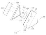
Figure 19 is an exploded perspective view of a pressure-operated pedal device for an autonomous vehicle according to the present invention.
Fig. 20 is a rear perspective view of the combined state of Fig. 19.
Fig. 21 is a rear perspective view of the pedal pad of Fig. 19.
Figure 22 is a drawing of a pressure-operated accelerator pedal device and a pressure-operated brake pedal device combined as a set according to the present invention and installed in the lower space of the driver's seat.
Figures 23 and 24 are drawings for explaining the shape and arrangement structure of a foldable accelerator pedal device and a foldable brake pedal device according to the present invention.
Figure 25 is a drawing of a state in which a foldable organ-type accelerator pedal device and a foldable pendant-type brake pedal device are combined as a set and installed in the lower space of the driver's seat according to the present invention.
Figure 26 is a drawing of a state in which a foldable organ-type accelerator pedal device and a pressure-operated brake pedal device are combined as a set and installed in the lower space of the driver's seat according to the present invention.
Figure 27 is a drawing of a state in which a foldable pendant type accelerator pedal device and a foldable organ type brake pedal device are combined as a set and installed in the lower space of the driver's seat according to the present invention.
Figure 28 is a drawing of a state in which a foldable pendant type accelerator pedal device and a pressure-operated brake pedal device are combined as a set according to the present invention and installed in the lower space of the driver's seat.
Figure 29 is a drawing of a pressure-operated accelerator pedal device and a foldable organ-type brake pedal device combined as a set according to the present invention, installed in the lower space of the driver's seat.
Figure 30 is a drawing of a state in which a pressure-operated accelerator pedal device and a foldable pendant-type brake pedal device are combined as a set and installed in the lower space of the driver's seat according to the present invention.
이하에서는 첨부된 도면을 참조하여 본 발명의 바람직한 실시 예에 따른 폴더블 가속페달장치 및 폴더블 브레이크페달장치를 구비한 자율주행 차량에 대해 살펴보기로 한다.Hereinafter, with reference to the attached drawings, an autonomous vehicle equipped with a foldable accelerator pedal device and a foldable brake pedal device according to a preferred embodiment of the present invention will be described.
먼저, 도 1 내지 도 9에는 폴더블 오르간타입 페달장치가 도시되어 있으며, 폴더블 오르간타입 페달장치는 자율주행 차량에서 사용이 가능한 구성이고, 특히 폴더블 오르간타입 페달장치는 폴더블 오르간타입 가속페달장치 및 폴더블 오르간타입 브레이크페달장치로서 사용이 모두 가능한 구성을 갖는다.First, FIGS. 1 to 9 illustrate a foldable organ-type pedal device. The foldable organ-type pedal device has a configuration that can be used in an autonomous vehicle, and in particular, the foldable organ-type pedal device has a configuration that can be used as both a foldable organ-type accelerator pedal device and a foldable organ-type brake pedal device.
도시된 바와 같이 폴더블 오르간타입 페달장치는, 운전석 하부공간에 고정되게 설치되고 운전자를 향하는 후방으로 하우징구멍(11)이 형성된 페달하우징(10); 상기 하우징구멍(11)에 위치하면서 하단이 페달하우징(10)에 회전 가능하도록 힌지 결합된 페달패드(20); 상기 페달하우징(10)과 페달패드(20)를 연결하는 페달링크(30); 및 상기 페달하우징(10)에 고정 설치되고 페달링크(30)와 연결된 것으로 페달링크(30)를 회전시키도록 동력을 발생하는 액추에이터(40)를 포함한다.As described above, the foldable organ-type pedal device includes a pedal housing (10) that is fixedly installed in a space below a driver's seat and has a housing hole (11) formed toward the rear toward the driver; a pedal pad (20) that is positioned in the housing hole (11) and hingedly connected at the bottom to the pedal housing (10) so as to be rotatable; a pedal link (30) that connects the pedal housing (10) and the pedal pad (20); and an actuator (40) that is fixedly installed in the pedal housing (10) and connected to the pedal link (30) and generates power to rotate the pedal link (30).
페달하우징(10)은 외형이 삼각형 모양으로 형성되어서 전방면은 차체를 구성하는 대시패널에 고정되고, 바닥면은 차체를 구성하는 운전석 하부공간의 플로어패널에 고정되게 설치되며, 내부는 비어있는 구조로 형성된다.The pedal housing (10) is formed with a triangular shape on the outside, so that the front surface is fixed to the dash panel forming the vehicle body, the bottom surface is installed to be fixed to the floor panel of the lower space of the driver's seat forming the vehicle body, and the inside is formed with an empty structure.
페달하우징(10)의 전방면과 바닥면은 직각을 이루도록 배치되고, 운전자를 향하는 후방면(12)은 경사면으로 배치되며, 운전자를 향하는 후방면(12)에 페달패드(20)가 설치되는 하우징구멍(11)이 형성된다.The front and bottom surfaces of the pedal housing (10) are arranged to form a right angle, the rear surface (12) facing the driver is arranged as an inclined surface, and a housing hole (11) in which a pedal pad (20) is installed is formed in the rear surface (12) facing the driver.
페달패드(20)는 페달하우징(10)의 하우징구멍(11)에 위치하고, 페달패드(20)의 하단은 힌지핀(51)에 의해 관통되고, 힌지핀(51)의 양단은 페달하우징(10)을 관통하면서 페달하우징(10)에 고정되게 결합된다.The pedal pad (20) is positioned in the housing hole (11) of the pedal housing (10), the lower end of the pedal pad (20) is penetrated by a hinge pin (51), and both ends of the hinge pin (51) are fixedly connected to the pedal housing (10) while penetrating the pedal housing (10).
따라서, 페달패드(20)는 하단의 힌지핀(51)을 중심으로 상단이 전후방향으로 회전하는 구조로, 페달패드(20)의 상단이 전방으로 회전하면 페달패드(20)는 페달하우징(10)의 하우징구멍(11)속으로 삽입되어서 하우징구멍(11)을 밀폐시키게 되고, 페달패드(20)의 상단이 후방으로 페달패드(20)는 페달하우징(10)의 하우징구멍(11)으로부터 운전자를 향하는 후방으로 돌출된다.Accordingly, the pedal pad (20) is structured so that the upper part rotates forward and backward around the hinge pin (51) at the bottom. When the upper part of the pedal pad (20) rotates forward, the pedal pad (20) is inserted into the housing hole (11) of the pedal housing (10) to seal the housing hole (11), and the upper part of the pedal pad (20) protrudes rearward from the housing hole (11) of the pedal housing (10) toward the driver.
액추에이터(40)는 모터로 구성될 수 있다.The actuator (40) may be composed of a motor.
본 발명에 따른 실시예는, 힌지핀(51)에 감겨진 형태로 설치되고 양단이 페달패드(20)와 힌지핀(51)에 고정되게 설치된 메인스프링(60), 및 상기 페달패드(20)와 페달링크(30)를 연결하게 설치된 서브스프링(70);을 더 포함한다.An embodiment according to the present invention further includes a main spring (60) that is installed in a wound form around a hinge pin (51) and has both ends fixed to the pedal pad (20) and the hinge pin (51), and a sub spring (70) that is installed to connect the pedal pad (20) and the pedal link (30).
메인스프링(60)은 페달패드(20)가 페달하우징(10)으로부터 운전자를 향하는 후방으로 돌출되는 회전을 할 때에 압축되면서 탄성력을 축적하고, 페달패드(20)가 하우징구멍(11)을 밀폐시키는 전방으로 회전할 때에 축적된 탄성력이 풀리면서 형상이 복원되는 토션스프링인 것이 바람직하지만, 이에 한정되는 것은 아니다.It is preferable that the main spring (60) be a torsion spring that accumulates elastic force by being compressed when the pedal pad (20) rotates to protrude rearwardly from the pedal housing (10) toward the driver, and restores its shape by releasing the accumulated elastic force when the pedal pad (20) rotates forward to seal the housing hole (11), but is not limited thereto.
서브스프링(70)은 페달패드(20)가 페달하우징(10)으로부터 운전자를 향하는 후방으로 돌출되는 회전을 할 때에 압축되면서 탄성력을 축적하고, 페달패드(20)가 하우징구멍(11)을 밀폐시키는 전방으로 회전할 때에 복원되는 압축코일스프링인 것이 바람직하지만, 이에 한정되는 것은 아니다.It is preferable, but not limited to, that the subspring (70) is a compression coil spring that accumulates elasticity by being compressed when the pedal pad (20) rotates to protrude rearwardly from the pedal housing (10) toward the driver, and is restored when the pedal pad (20) rotates forward to seal the housing hole (11).
본 발명에 따른 실시예는 메인스프링(60)의 탄성력이 서브스프링(70)의 탄성력보다 더 큰 탄성력으로 구성되는 것이 특징으로, 이를 통해 액추에이터(40)의 미작동시 메인스프링(60)의 탄성력으로 페달패드(20)를 전방으로 회전시켜서 페달패드(20)를 하우징구멍(11)속에 위치시킬 수가 있게 된다.An embodiment according to the present invention is characterized in that the elasticity of the main spring (60) is configured to be greater than the elasticity of the sub spring (70), so that when the actuator (40) is not in operation, the pedal pad (20) can be rotated forward by the elasticity of the main spring (60) to position the pedal pad (20) in the housing hole (11).
페달패드(20)가 페달하우징(10)으로부터 운전자를 향하는 후방으로 돌출된 상태일 때, 즉 페달패드(20)가 팝업(pop up)된 상태일 때, 운전자가 페달패드(20)를 밟아서 조작하면 메인스프링(60)의 탄성력과 서브스프링(70)의 탄성력이 모두 반력으로 작용함에 따라 답력을 구현할 수 있게 된다.When the pedal pad (20) is in a state where it protrudes rearwardly from the pedal housing (10) toward the driver, that is, when the pedal pad (20) is in a pop-up state, when the driver steps on the pedal pad (20) to operate it, the elastic force of the main spring (60) and the elastic force of the sub spring (70) both act as a counter force, thereby enabling the implementation of a pressure.
서브스프링(70)이 없더라도 메인스프링(60)의 탄성력만으로도 충분히 답력을 구현할 수 있지만, 페달 답력의 정확한 튜닝을 위해 메인스프링(60)과 서브스프링(70)이 함께 구성되는 것이 보다 바람직할 것이다.Even without the sub spring (70), the elasticity of the main spring (60) alone can sufficiently implement the pedaling force, but it would be more desirable to configure the main spring (60) and the sub spring (70) together for precise tuning of the pedaling force.
본 발명에 따른 실시예는 페달링크(30)에 결합된 것으로 페달패드(20)가 페달하우징(10)으로부터 운전자를 향하는 후방으로 돌출되는 회전을 할 때에 페달하우징(10)과의 접촉으로 페달패드(20)의 후방 회전각을 제어하는 스토퍼(80), 상기 페달링크(30)에서 페달하우징(10)에 회전 가능하게 결합되는 링크축(31a)에 고정되게 결합된 영구자석(90, 마그넷), 및 상기 페달하우징(10)에 결합되는 측면커버(100)에서 영구자석(90)과 대면되게 설치된 것으로 페달링크(30)의 회전시 영구자석(90)의 회전위치변화에 따른 자기장 세기의 변화를 통해 페달패드(20)의 회전각을 검출하는 비접촉 페달센서(110)를 더 포함한다.An embodiment according to the present invention further includes a stopper (80) that controls the rearward rotation angle of the pedal pad (20) by contact with the pedal housing (10) when the pedal pad (20) is coupled to the pedal link (30) and rotates to protrude rearwardly from the pedal housing (10) toward the driver, a permanent magnet (90, magnet) that is fixedly coupled to a link shaft (31a) that is rotatably coupled to the pedal housing (10) in the pedal link (30), and a non-contact pedal sensor (110) that is installed so as to face the permanent magnet (90) in a side cover (100) coupled to the pedal housing (10) and detects the rotation angle of the pedal pad (20) by changing the magnetic field intensity according to the change in the rotational position of the permanent magnet (90) when the pedal link (30) rotates.
페달링크(30)에 결합된 스토퍼(80)는 페달패드(20)가 페달하우징(10)으로부터 운전자를 향하는 후방으로 돌출되는 회전을 할 때에 페달하우징(10)의 후방면(12)의 안쪽면과 접촉하고, 이를 통해 페달패드(20)의 후방 회전각을 구속하게 되며, 스토퍼(80)는 페달하우징(10)과의 접촉시 소음방지를 위해 고무 또는 실리콘 또는 합성수지 중 어느 하나로 형성된 것이 바람직하지만, 이에 한정되지는 않는다.The stopper (80) coupled to the pedal link (30) comes into contact with the inner surface of the rear surface (12) of the pedal housing (10) when the pedal pad (20) rotates to protrude rearward from the pedal housing (10) toward the driver, thereby restricting the rearward rotation angle of the pedal pad (20). The stopper (80) is preferably formed of one of rubber, silicone, or synthetic resin to prevent noise when in contact with the pedal housing (10), but is not limited thereto.
페달센서(110)는 PCB(Printed Circuit Board)를 구비한 구성이고, 페달링크(30)의 회전중심 역할을 하는 링크축(31a)에 영구자석(90)이 위치하는 구성으로, 이를 통해 페달센서(110)의 출력신호의 정확도를 한층 더 높일 수 있는 장점이 있다.The pedal sensor (110) is configured with a PCB (Printed Circuit Board) and has a permanent magnet (90) positioned on a link shaft (31a) that serves as the center of rotation of the pedal link (30). This has the advantage of further increasing the accuracy of the output signal of the pedal sensor (110).
본 발명에 따른 페달링크(30)는 페달하우징(10)에 회전 가능하게 결합되는 링크축(31a)이 형성되고 액추에이터(40)와 동력전달이 가능하도록 연결된 회전링크(31), 및 상기 회전링크(31)와 페달패드(20)를 연결하도록 양단이 회전 가능하게 힌지 결합된 연결링크(32)를 포함한다.A pedal link (30) according to the present invention includes a rotation link (31) formed with a link shaft (31a) that is rotatably coupled to a pedal housing (10) and connected to an actuator (40) so as to transmit power, and a connecting link (32) whose ends are rotatably hinge-coupled to connect the rotation link (31) and a pedal pad (20).
회전링크(31)의 하단에 링크축(31a)이 형성되고, 링크축(31a)이 페달하우징(10)의 바닥부에 회전 가능하게 결합되고, 회전링크(31)는 액추에이터(40)와 연결결되어서 액추에이터(40)의 동력으로 회전한다.A link shaft (31a) is formed at the bottom of the rotary link (31), the link shaft (31a) is rotatably connected to the bottom of the pedal housing (10), and the rotary link (31) is connected to an actuator (40) and rotates by the power of the actuator (40).
회전링크(31)의 상단은 제1핀(52)을 매개로 연결링크(32)의 후방 일단과 회전 가능하게 결합되고, 연결링크(32)의 전방 타단은 제2핀(53)을 매개로 페달패드(20)와 회전 가능하게 결합된다.The upper end of the rotary link (31) is rotatably connected to the rear end of the connecting link (32) via the first pin (52), and the front end of the connecting link (32) is rotatably connected to the pedal pad (20) via the second pin (53).
본 발명에 따라 회전링크(31)와 연결링크(32)가 이루는 사이각은 페달패드(20)의 회전에 상관없이 항상 예각을 이루는 구성으로, 페달패드(20)가 페달하우징(10)으로부터 운전자를 향하는 후방으로 돌출되는 회전을 할 때에 회전링크(31)와 연결링크(32)가 둔각을 이루게 되면, 페달패드(20)가 너무 과도하게 후방으로 돌출됨에 따라 운전자가 발로 페달패드(20)를 정확하게 밟을 수 없는 문제가 발생하게 되는 바, 이를 예방하기 위해 회전링크(31)와 연결링크(32)가 이루는 사이각은 페달패드(20)의 회전에 상관없이 항상 예각을 이루는 구성인 것이 바람직할 것이다.According to the present invention, the angle formed between the rotation link (31) and the connection link (32) is configured to always form an acute angle regardless of the rotation of the pedal pad (20). When the pedal pad (20) rotates to protrude rearward from the pedal housing (10) toward the driver, if the rotation link (31) and the connection link (32) form an obtuse angle, the pedal pad (20) protrudes too excessively rearward, causing a problem in which the driver cannot accurately step on the pedal pad (20) with his or her foot. In order to prevent this, it is preferable that the angle formed between the rotation link (31) and the connection link (32) always form an acute angle regardless of the rotation of the pedal pad (20).
본 발명에 따라 회전링크(31)에는 페달패드(20)와 연결되는 서브스프링(70)의 일단이 결합되고, 회전링크(31)의 링크축(31a)의 단부에는 영구자석(90)이 고정되게 결합되며, 연결링크(32)에는 페달하우징(10)과의 접촉으로 페달패드(20)의 후방 회전각을 제어하는 스토퍼(80)가 삽입되도록 스토퍼구멍(32a)이 형성된다.According to the present invention, one end of a sub-spring (70) connected to a pedal pad (20) is coupled to a rotary link (31), a permanent magnet (90) is fixedly coupled to an end of a link shaft (31a) of the rotary link (31), and a stopper hole (32a) is formed in the connecting link (32) so that a stopper (80) for controlling the rearward rotation angle of the pedal pad (20) by contact with the pedal housing (10) is inserted.
따라서, 운전자가 자율주행모드를 선택하면 액추에이터(40)의 구동력 및 메인스프링(60)의 탄성력에 의해 페달패드(20)는 하단의 힌지핀(51)을 중심으로 상단이 전방으로 회전해서 페달하우징(10)의 하우징구멍(11)속으로 삽입되어서 하우징구멍(11)을 밀폐시키게 되며, 이때의 페달패드(20)는 페달하우징(10)의 후방면(12)과 동일평면을 이루게 됨으로써 페달패드(20)가 숨겨진 하이드(hide) 상태가 된다.(도 2 내지 도 4 참고)Therefore, when the driver selects the autonomous driving mode, the pedal pad (20) rotates forward at the top around the hinge pin (51) at the bottom by the driving force of the actuator (40) and the elastic force of the main spring (60) and is inserted into the housing hole (11) of the pedal housing (10) to seal the housing hole (11). At this time, the pedal pad (20) becomes flush with the rear surface (12) of the pedal housing (10), thereby putting the pedal pad (20) into a hidden state. (Refer to FIGS. 2 to 4)
페달패드(20)가 페달하우징(10)의 하우징구멍(11)속으로 삽입되어서 숨겨진 상태가 되면, 운전석 하부공간은 페달이 없는 넓은 공간이 됨에 따라 운전자는 릴렉스모드에서 편안한 휴식을 취할 수가 있게 된다.When the pedal pad (20) is inserted into the housing hole (11) of the pedal housing (10) and becomes hidden, the space below the driver's seat becomes a wide space without pedals, allowing the driver to rest comfortably in relaxation mode.
또한, 페달패드(20)가 페달하우징(10)의 하우징구멍(11)속으로 삽입되어서 숨겨진 상태가 되면 운전석 하부공간으로 페달이 노출되지 않게 됨에 따라, 자율주행 상황에서 운전자가 페달을 오조작하는 상황도 미리 예방할 수 있는 장점이 있다.In addition, since the pedal pad (20) is inserted into the housing hole (11) of the pedal housing (10) and hidden, the pedal is not exposed to the space below the driver's seat, so there is an advantage in that it can prevent the driver from incorrectly operating the pedal in an autonomous driving situation.
그리고, 운전자가 직접 운전을 하는 수동운전모드를 선택하면 액추에이터(40)의 구동력과 페달링크(30)의 회전작동 및 스프링의 변형에 의해 페달패드(20)는 하단의 힌지핀(51)을 중심으로 상단이 운전자가 있는 후방으로 회전해서 페달하우징(10)의 하우징구멍(11)으로부터 돌출된 팝업(pop up) 상태가 된다.(도 5 내지 도 8 참고)And, when the driver selects the manual driving mode in which the driver drives directly, the pedal pad (20) rotates toward the rear toward the driver with the upper part centered on the hinge pin (51) at the bottom due to the driving force of the actuator (40), the rotational operation of the pedal link (30), and the deformation of the spring, and becomes a pop-up state protruding from the housing hole (11) of the pedal housing (10). (Refer to FIGS. 5 to 8)
페달패드(20)가 운전자가 있는 후방으로 회전해서 페달하우징(10)으로부터 돌출된 팝업상태가 되면, 운전자는 페달패드(20)를 발로 조작해서 차량의 주행에 필요한 가속 또는 브레이크를 제어하게 된다.When the pedal pad (20) rotates toward the rear where the driver is and becomes a pop-up state protruding from the pedal housing (10), the driver controls the acceleration or braking required for driving the vehicle by operating the pedal pad (20) with his or her foot.
운전자가 팝업된 페달패드(20)를 밟아서 조작할 때에 메인스프링(60)의 탄성력과 서브스프링(70)의 탄성력이 모두 반력으로 작용함에 따라 답력이 구현된다.When the driver steps on the pop-up pedal pad (20) to operate, the elastic force of the main spring (60) and the elastic force of the sub spring (70) both act as a reaction force, thereby implementing the pressure.
한편, 본 발명 실시예에 따른 폴더블 오르간타입 페달장치는 도 9에 도시된 바와 같이 한 대의 자율주행 차량에서 폴더블 오르간타입 가속페달장치(1000) 및 폴더블 오르간타입 브레이크페달장치(2000)로서 모두 사용이 가능한 것이 특징이다.Meanwhile, the foldable organ-type pedal device according to the embodiment of the present invention is characterized in that it can be used as both a foldable organ-type accelerator pedal device (1000) and a foldable organ-type brake pedal device (2000) in one autonomous vehicle, as illustrated in FIG. 9.
전술한 바와 같이 본 발명에 따른 폴더블 오르간타입 페달장치가 한 대의 자율주행 차량에서 폴더블 오르간타입 가속페달장치(1000)와 폴더블 오르간타입 브레이크페달장치(2000)로서 함께 사용되는 경우 폴더블 오르간타입 가속페달장치(1000)는 운전석 하부의 공간(120)에서 콘솔(130)의 측면에 밀착되도록 설치되고, 폴더블 오르간타입 브레이크페달장치(2000)는 폴더블 오르간타입 가속페달장치(1000)의 일측면에 밀착되도록 설치된다.As described above, when the foldable organ-type pedal device according to the present invention is used together as a foldable organ-type accelerator pedal device (1000) and a foldable organ-type brake pedal device (2000) in one autonomous vehicle, the foldable organ-type accelerator pedal device (1000) is installed so as to be in close contact with the side of the console (130) in the space (120) under the driver's seat, and the foldable organ-type brake pedal device (2000) is installed so as to be in close contact with one side of the foldable organ-type accelerator pedal device (1000).
이때, 폴더블 오르간타입 가속페달장치(1000)에서 콘솔(130)에 밀착되는 페달하우징(10)의 일측면은 측면커버(100)없이 개구된 구조(140)로 설치되고, 개구된 구조(140)는 콘솔(130)에 의해 차단되므로 외부로의 노출이 없고, 이물질이 유입되는 것도 방지되며, 이를 통해 중량감소 및 원가절감을 도모할 수 있다.At this time, one side of the pedal housing (10) that is in close contact with the console (130) of the foldable organ-type accelerator pedal device (1000) is installed as an open structure (140) without a side cover (100), and the open structure (140) is blocked by the console (130), so that there is no exposure to the outside, and the inflow of foreign substances is prevented, thereby helping to reduce weight and cost.
그리고, 폴더블 오르간타입 가속페달장치(1000)에서 폴더블 오르간타입 브레이크페달장치(2000)와 밀착되는 타측면 및 폴더블 오르간타입 브레이크페달장치(2000)의 양쪽 측면은 모두 측면커버(100)에 의해 밀폐되는 구조로 설치되는 바, 이를 통해 충분한 강도 및 강성 확보가 가능하고, 외부로의 노출이 없으며, 특히 이물질의 유입을 차단할 수 있다.In addition, the other side of the foldable organ-type accelerator pedal device (1000) that is in close contact with the foldable organ-type brake pedal device (2000) and both sides of the foldable organ-type brake pedal device (2000) are installed in a structure in which they are sealed by a side cover (100), thereby ensuring sufficient strength and rigidity, preventing exposure to the outside, and in particular blocking the inflow of foreign substances.
다음으로, 도 10 내지 도 18에는 폴더블 펜던트타입 페달장치가 도시되어 있으며, 폴더블 펜던트타입 페달장치는 자율주행 차량에서 사용이 가능한 구성이고, 특히 폴더블 펜던트타입 페달장치는 폴더블 펜던트타입 가속페달장치 및 폴더블 펜던트타입 브레이크페달장치로서 사용이 모두 가능한 구성을 갖는다.Next, FIGS. 10 to 18 illustrate a foldable pendant type pedal device. The foldable pendant type pedal device has a configuration that can be used in an autonomous vehicle, and in particular, the foldable pendant type pedal device has a configuration that can be used as both a foldable pendant type accelerator pedal device and a foldable pendant type brake pedal device.
도시된 바와 같이 폴더블 펜던트타입 페달장치는, 운전석 하부공간에 고정되게 설치되고 운전자를 향하는 후방으로 하우징구멍(311)이 형성된 페달하우징(310); 상기 페달하우징(310)에 전후방향으로 회전 가능하도록 힌지 결합된 페달암(320); 상기 페달암(320)에 구비된 것으로 페달암(320)이 전방으로 회전할 때에 하우징구멍(311)을 밀폐시키고 페달암(320)이 후방으로 회전할 때에 페달하우징(310)으로부터 운전자를 향하는 후방으로 돌출되게 동작하는 페달패드(330); 및 상기 페달하우징(310)에 고정 설치되고 페달암(320)과 연결된 것으로 페달암(320)을 회전시키도록 동력을 발생하는 액추에이터(340);를 포함한다.As described above, the foldable pendant type pedal device includes: a pedal housing (310) fixedly installed in a space below a driver's seat and having a housing hole (311) formed toward the rear toward the driver; a pedal arm (320) hinge-connected to the pedal housing (310) so as to be rotatable in the forward and backward directions; a pedal pad (330) provided on the pedal arm (320) that seals the housing hole (311) when the pedal arm (320) rotates forward and protrudes rearward from the pedal housing (310) toward the driver when the pedal arm (320) rotates backward; and an actuator (340) fixedly installed on the pedal housing (310) and connected to the pedal arm (320) that generates power to rotate the pedal arm (320).
페달하우징(310)은 개략적인 외형이 사각박스 모양으로 형성되면서 후방면이 윗면보다 더 상측으로 돌출되면서 전방으로 경사지게 형성된 모양이고, 전방면은 차체를 구성하는 대시패널에 고정되고, 바닥면(312)은 차체를 구성하는 운전석 하부공간의 플로어패널에 고정되게 설치되며, 내부는 비어있는 구조로 형성된다.The pedal housing (310) is formed in a general rectangular box shape with the rear surface protruding upward more than the upper surface and slanted forward. The front surface is fixed to the dash panel forming the vehicle body, the bottom surface (312) is installed to be fixed to the floor panel of the lower space of the driver's seat forming the vehicle body, and the interior is formed in an empty structure.
페달하우징(10)의 전방면과 바닥면(312)은 직각을 이루도록 배치되고, 운전자를 향하는 후방면(313)은 경사면으로 배치되며, 운전자를 향하는 후방면(313)에 페달패드(20)가 설치되는 하우징구멍(311)이 형성된다.The front surface and the bottom surface (312) of the pedal housing (10) are arranged to form a right angle, the rear surface (313) facing the driver is arranged as an inclined surface, and a housing hole (311) in which a pedal pad (20) is installed is formed in the rear surface (313) facing the driver.
하우징구멍(311)은 사각구멍으로 형성된 것이 일예로서 도시되어 있지만 사각구멍 이외에 다양한 형상으로도 형성이 가능할 것이다.The housing hole (311) is shown as an example of a square hole, but it can be formed in various shapes other than a square hole.
페달암(320)은 페달하우징(310)의 내부공간에 위치하면서 상단이 페달하우징(310)에 힌지 결합되어서 회전중심 역할을 하고, 하단이 상단을 중심으로 전후방향으로 회전하는 구성이다.The pedal arm (320) is positioned in the internal space of the pedal housing (310), and the upper part is hingedly connected to the pedal housing (310) to serve as a center of rotation, and the lower part rotates forward and backward around the upper part.
페달패드(330)는 페달하우징(310)의 후방면(313)의 바깥측에 위치하도록 구성되고, 페달암(320)은 페달하우징(310)의 후방면(313)에 형성된 하우징구멍(311)을 관통한 후 페달패드(330)와 연결되게 구성된다.The pedal pad (330) is configured to be positioned on the outer side of the rear surface (313) of the pedal housing (310), and the pedal arm (320) is configured to pass through the housing hole (311) formed on the rear surface (313) of the pedal housing (310) and then be connected to the pedal pad (330).
페달패드(330)는 페달암(320)과 일체로 형성되거나, 또는 페달암(320)과 페달패드(330)가 각각 별물로 제작된 후 결합부재를 통해 일체화가 되도록 결합된 구조가 될 수도 있다.The pedal pad (330) may be formed integrally with the pedal arm (320), or the pedal arm (320) and the pedal pad (330) may be manufactured separately and then integrated through a joining member.
따라서, 페달암(320)이 페달하우징(310)과 힌지 결합된 상단을 중심으로 하단이 후방으로 회전하면 페달패드(330)는 페달하우징(310)의 하우징구멍(311)으로부터 운전자를 향하는 후방으로 돌출되고, 페달패드(330)가 페달하우징(310)으로부터 후방으로 돌출된 상태에서 페달암(320)이 전방으로 회전하면 후방으로 돌출된 페달패드(330)는 페달하우징(310)의 후방면(313)을 향해 이동해서 후방면(313)에 형성된 하우징구멍(311)을 밀폐시키게 된다.Accordingly, when the pedal arm (320) rotates rearwardly with its lower end centered on the upper end hingedly connected to the pedal housing (310), the pedal pad (330) protrudes rearwardly toward the driver from the housing hole (311) of the pedal housing (310), and when the pedal arm (320) rotates forward while the pedal pad (330) protrudes rearwardly from the pedal housing (310), the pedal pad (330) protruding rearwardly moves toward the rear surface (313) of the pedal housing (310) to seal the housing hole (311) formed in the rear surface (313).
액추에이터(340)는 모터로 구성될 수 있다.The actuator (340) may be composed of a motor.
본 발명에 따른 실시예는, 페달암(320)의 회전중심부위에 위치하면서 페달하우징(310)과 페달암(320)에 양단이 고정되게 조작력스프링(350), 및 전후방향으로 연장되면서 페달암(320)의 몸통부위와 페달하우징(310)에 양단이 고정되게 설치된 복귀스프링(360)을 더 포함한다.An embodiment according to the present invention further includes an operating force spring (350) positioned at the center of rotation of the pedal arm (320) and having both ends fixed to the pedal housing (310) and the pedal arm (320), and a return spring (360) extended in the forward and backward direction and having both ends fixed to the body of the pedal arm (320) and the pedal housing (310).
조작력스프링(350)은 페달패드(330)가 하우징구멍(311)을 밀폐시키도록 페달암(320)이 전방으로 회전할 때에 압축되면서 탄성력을 축적하고, 페달패드(330)가 페달하우징(310)으로부터 운전자를 향해 돌출되도록 페달암(320)이 후방으로 회전할 때에 축적된 탄성력이 풀리면서 형상이 복원되는 토션스프링인 것이 바람직하지만, 이에 한정되는 것은 아니다.The operating force spring (350) is preferably a torsion spring that accumulates elastic force by being compressed when the pedal arm (320) rotates forward so that the pedal pad (330) seals the housing hole (311), and restores its shape by releasing the accumulated elastic force when the pedal arm (320) rotates backward so that the pedal pad (330) protrudes from the pedal housing (310) toward the driver, but is not limited thereto.
복귀스프링(360)은 페달패드(330)가 페달하우징(310)으로부터 운전자를 향해 돌출되도록 페달암(320)이 후방으로 회전할 때에 압축되면서 탄성력을 축적하고, 페달패드(330)가 하우징구멍(311)을 밀폐시키도록 페달암(320)이 전방으로 회전할 때에 축적된 탄성력이 풀리면서 형상이 복원되는 압축코일스프링인 것이 바람직하지만, 이에 한정되는 것은 아니다.The return spring (360) is preferably a compression coil spring that accumulates elastic force by being compressed when the pedal arm (320) rotates rearward so that the pedal pad (330) protrudes from the pedal housing (310) toward the driver, and restores its shape by releasing the accumulated elastic force when the pedal arm (320) rotates forward so that the pedal pad (330) seals the housing hole (311), but is not limited thereto.
본 발명에 따른 실시예는 복귀스프링(360)의 탄성력이 조작력스프링(350)의 탄성력보다 더 큰 탄성력으로 구성되는 것이 특징으로, 이를 통해 액추에이터(340)의 미작동시 복귀스프링(360)의 탄성력으로 페달암(320)을 전방으로 회전시켜서 페달패드(330)에 의해 하우징구멍(311)이 밀폐되도록 페달패드(330)를 페달하우징(310)의 후방면(313)에 밀착시킬 수가 있게 된다.An embodiment according to the present invention is characterized in that the elasticity of the return spring (360) is configured to be greater than the elasticity of the operating force spring (350), so that when the actuator (340) is not in operation, the pedal arm (320) is rotated forward by the elasticity of the return spring (360), thereby allowing the pedal pad (330) to be pressed against the rear surface (313) of the pedal housing (310) so that the housing hole (311) is sealed by the pedal pad (330).
페달패드(330)가 페달하우징(310)으로부터 운전자를 향하는 후방으로 돌출된 상태일 때, 즉 페달패드(330)가 팝업(pop up)된 상태일 때, 운전자가 페달패드(330)를 밟아서 조작하면 조작력스프링(350)의 탄성력과 복귀스프링(360)의 탄성력이 모두 반력으로 작용함에 따라 답력을 구현할 수 있게 된다.When the pedal pad (330) is in a state where it protrudes rearwardly from the pedal housing (310) toward the driver, that is, when the pedal pad (330) is in a pop-up state, when the driver steps on the pedal pad (330) to operate it, the elastic force of the operating force spring (350) and the elastic force of the return spring (360) both act as a counter force, thereby enabling the implementation of a pressure.
조작력스프링(350)이 없더라도 복귀스프링(360)의 탄성력만으로도 충분히 답력을 구현할 수 있지만, 페달 답력의 정확한 튜닝을 위해 조작력스프링(350)과 복귀스프링(360)이 함께 구성되는 것이 보다 바람직할 것이다.Even without the operating force spring (350), the elasticity of the return spring (360) alone can sufficiently implement the pedaling force, but it would be more desirable to configure the operating force spring (350) and the return spring (360) together for precise tuning of the pedaling force.
본 발명에 따른 페달암(320)은 상단에 페달하우징(310)에 힌지 결합되는 페달암축(321)이 형성되고 하단에 스토퍼부(322)가 형성되며 페달암축(321)이 위치한 부위에 조작력스프링(350)의 일단이 결합되는 수직로드부(323), 상기 수직로드부(323)에 일단이 연결되고 타단은 하우징구멍(311)을 관통해서 페달패드(330)와 연결되는 경사로드부(324), 및 상기 수직로드부(323)와 경사로드부(324)를 연결하고 복귀스프링(360)의 일단이 결합되는 연결로드부(325)를 포함한다.A pedal arm (320) according to the present invention includes a pedal arm shaft (321) formed at the top hinge-connected to a pedal housing (310), a stopper part (322) formed at the bottom, a vertical rod part (323) to which one end of an operating force spring (350) is coupled at a location where the pedal arm shaft (321) is located, an inclined rod part (324) to which one end is connected to the vertical rod part (323) and the other end is connected to a pedal pad (330) by penetrating a housing hole (311), and a connecting rod part (325) to which one end of a return spring (360) is coupled and which connects the vertical rod part (323) and the inclined rod part (324).
또한, 본 발명은 페달하우징(310)의 바닥면(312)에서 페달하우징(310)의 내부공간 상측으로 돌출되게 구비된 하우징돌기(370), 및 페달암(320)의 후방 회전시 하우징돌기(370)와의 접촉하도록 페달암(320)에 구비된 스토퍼부(322)를 더 포함한다.In addition, the present invention further includes a housing protrusion (370) provided to protrude upwardly from the inner space of the pedal housing (310) from the bottom surface (312) of the pedal housing (310), and a stopper part (322) provided on the pedal arm (320) to come into contact with the housing protrusion (370) when the pedal arm (320) rotates rearward.
따라서, 본 발명에 따른 실시예는 페달암(320)의 후방 회전시 페달암(320)에 구비된 스토퍼부(322)가 페달하우징(310)에 구비된 하우징돌기(370)에 접촉함에 따라 페달암(320)의 후방 회전각이 제어되는 구성이 된다.Accordingly, the embodiment according to the present invention is configured such that the rearward rotation angle of the pedal arm (320) is controlled when the stopper part (322) provided on the pedal arm (320) comes into contact with the housing protrusion (370) provided on the pedal housing (310) when the pedal arm (320) rotates rearward.
그리고, 본 발명에 따른 페달패드(330)는 페달하우징(310)에 형성된 하우징구멍(311)보다 더 큰 면적으로 형성된 것이 특징으로, 이를 통해 페달암(320)의 전방 회전시 페달패드(330)가 하우징구멍(311)을 통과하지 못하고 페달하우징(310)의 후방면(313)에 밀착되도록 접촉함에 따라 페달암(320)의 전방 회전각이 제어되는 구성이 된다.In addition, the pedal pad (330) according to the present invention is characterized by being formed with a larger area than the housing hole (311) formed in the pedal housing (310), so that when the pedal arm (320) rotates forward, the pedal pad (330) does not pass through the housing hole (311) but comes into close contact with the rear surface (313) of the pedal housing (310), thereby controlling the forward rotation angle of the pedal arm (320).
한편, 페달하우징(310)에 형성된 하우징돌기(370)는 페달암(320)의 스토퍼부(322)와의 접촉시 소음방지를 위해 고무 또는 실리콘 또는 합성수지 중 어느 하나로 형성된 것이 바람직하지만, 이에 한정되지는 않는다.Meanwhile, it is preferable that the housing protrusion (370) formed on the pedal housing (310) be formed of rubber, silicone or synthetic resin to prevent noise when in contact with the stopper portion (322) of the pedal arm (320), but it is not limited thereto.
또한 본 발명에 따른 실시예는, 페달암(320)에서 페달하우징(310)에 회전 가능하게 결합되는 페달암축(321)에 고정되게 결합된 영구자석(380, 마그넷), 및 상기 페달하우징(310)에 결합되는 측면커버(390)에서 영구자석(380)과 대면되게 설치된 것으로 페달암(320)의 회전시 영구자석(380)의 회전위치변화에 따른 자기장 세기의 변화를 통해 페달암(320)의 회전각을 검출하는 비접촉 페달센서(400)를 더 포함한다.In addition, an embodiment according to the present invention further includes a permanent magnet (380, magnet) fixedly coupled to a pedal arm shaft (321) that is rotatably coupled to a pedal housing (310) in a pedal arm (320), and a non-contact pedal sensor (400) that is installed so as to face the permanent magnet (380) in a side cover (390) coupled to the pedal housing (310) and detects a rotation angle of the pedal arm (320) through a change in magnetic field intensity according to a change in the rotational position of the permanent magnet (380) when the pedal arm (320) rotates.
페달센서(400)는 PCB(Printed Circuit Board)를 구비한 구성이고, 페달암(320)의 회전중심 역할을 하는 페달암축(321)에 영구자석(380)이 위치하는 구성으로, 이를 통해 페달센서(400)의 출력신호의 정확도를 한층 더 높일 수 있는 장점이 있다.The pedal sensor (400) is configured with a PCB (Printed Circuit Board) and a permanent magnet (380) is positioned on the pedal arm axis (321) that serves as the center of rotation of the pedal arm (320). This has the advantage of further increasing the accuracy of the output signal of the pedal sensor (400).
따라서, 운전자가 자율주행모드를 선택하면 액추에이터(340)의 구동력 및 복귀스프링(360)의 탄성력에 의해 페달암(320)은 상단의 페달암축(321)을 중심으로 하단이 전방으로 회전하고, 이를 통해 페달암(320)에 구비된 페달패드(330)는 페달하우징(310)의 후방면(313)을 향해 이동해서 하우징구멍(311)을 밀폐시키게 되며, 이때의 페달패드(330)는 페달하우징(310)의 후방면(313)에 밀착됨에 따라 페달패드(330)가 숨겨진 하이드(hide) 상태가 된다.(도 11 내지 도 13 참고)Therefore, when the driver selects the autonomous driving mode, the pedal arm (320) rotates forward at the lower end around the pedal arm axis (321) at the upper end by the driving force of the actuator (340) and the elastic force of the return spring (360), and through this, the pedal pad (330) provided on the pedal arm (320) moves toward the rear surface (313) of the pedal housing (310) to seal the housing hole (311), and at this time, the pedal pad (330) comes into close contact with the rear surface (313) of the pedal housing (310), thereby entering a hidden state. (Refer to FIGS. 11 to 13)
이와 같이, 페달패드(330)가 페달하우징(310)의 후방면(313)에 밀착된 숨겨진 상태가 되면, 운전석 하부공간은 페달이 없는 넓은 공간이 됨에 따라 운전자는 릴렉스모드에서 편안한 휴식을 취할 수가 있게 된다.In this way, when the pedal pad (330) is hidden and closely attached to the rear surface (313) of the pedal housing (310), the space below the driver's seat becomes a wide space without pedals, allowing the driver to rest comfortably in relaxation mode.
또한, 페달패드(330)가 페달하우징(310)의 후방면(313)에 밀착되어서 숨겨진 상태가 되면 운전석 하부공간으로 페달이 노출되지 않게 됨에 따라, 자율주행 상황에서 운전자가 페달을 오조작하는 상황도 미리 예방할 수 있는 장점이 있다.In addition, since the pedal pad (330) is hidden by being closely attached to the rear surface (313) of the pedal housing (310), the pedal is not exposed to the space below the driver's seat, which has the advantage of preventing the driver from incorrectly operating the pedal in an autonomous driving situation.
그리고, 운전자가 직접 운전을 하는 수동운전모드를 선택하면 액추에이터(340)의 구동력과 스프링의 변형에 의해 페달암(320)은 상단의 페달암축(321)을 중심으로 하단이 운전자가 있는 후방으로 회전하고, 이를 통해 페달암(320)에 구비된 페달패드(330)는 페달하우징(310)의 하우징구멍(311)으로부터 운전자가 있는 후방으로 돌출된 팝업(pop up) 상태가 된다.(도 14 내지 도 17 참고)And, when the driver selects the manual driving mode in which the driver drives directly, the pedal arm (320) rotates toward the rear where the driver is with the upper pedal arm axis (321) as the center by the driving force of the actuator (340) and the deformation of the spring, and through this, the pedal pad (330) provided on the pedal arm (320) pops up from the housing hole (311) of the pedal housing (310) toward the rear where the driver is. (Refer to FIGS. 14 to 17)
페달암(320)의 후방회전으로 페달패드(330)가 운전자가 있는 후방으로 돌출된 팝업상태가 되면, 운전자는 페달패드(330)를 발로 조작해서 차량의 주행에 필요한 가속 또는 브레이크를 제어하게 된다.When the pedal pad (330) is in a pop-up state protruding toward the rear where the driver is due to the rearward rotation of the pedal arm (320), the driver controls the acceleration or braking required for driving the vehicle by operating the pedal pad (330) with his or her foot.
운전자가 팝업된 페달패드(330)를 밟아서 조작할 때에 조작력스프링(350)의 탄성력과 복귀스프링(360)의 탄성력이 모두 반력으로 작용함에 따라 답력이 구현된다.When the driver steps on the pop-up pedal pad (330) to operate, the elastic force of the operating force spring (350) and the elastic force of the return spring (360) both act as a reaction force, thereby implementing the pressure.
한편, 본 발명 실시예에 따른 폴더블 펜던트타입 페달장치는 도 18에 도시된 바와 같이 한 대의 자율주행 차량에서 폴더블 펜던트타입 가속페달장치(3000) 및 폴더블 펜던트타입 브레이크페달장치(4000)로서 모두 사용이 가능한 것이 특징이다.Meanwhile, the foldable pendant type pedal device according to the embodiment of the present invention is characterized in that it can be used as both a foldable pendant type accelerator pedal device (3000) and a foldable pendant type brake pedal device (4000) in one autonomous vehicle, as illustrated in FIG. 18.
전술한 바와 같이 본 발명에 따른 폴더블 펜던트타입 페달장치가 한 대의 자율주행 차량에서 폴더블 펜던트타입 가속페달장치(3000)와 폴더블 펜던트타입 브레이크페달장치(4000)로서 함께 사용되는 경우 폴더블 펜던트타입 가속페달장치(3000)는 운전석 하부의 공간(120)에서 콘솔(130)의 측면에 밀착되도록 설치되고, 폴더블 펜던트타입 브레이크페달장치(4000)는 폴더블 펜던트타입 가속페달장치(3000)의 일측면에 밀착되도록 설치된다.As described above, when the foldable pendant type pedal device according to the present invention is used together as a foldable pendant type accelerator pedal device (3000) and a foldable pendant type brake pedal device (4000) in one autonomous vehicle, the foldable pendant type accelerator pedal device (3000) is installed so as to be in close contact with the side of the console (130) in the space (120) under the driver's seat, and the foldable pendant type brake pedal device (4000) is installed so as to be in close contact with one side of the foldable pendant type accelerator pedal device (3000).
이때, 폴더블 펜던트타입 가속페달장치(3000)에서 콘솔(130)에 밀착되는 페달하우징(310)의 일측면은 측면커버(390)없이 개구된 구조(410)로 설치되고, 개구된 구조(410)는 콘솔(130)에 의해 차단되므로 외부로의 노출이 없고, 이물질이 유입되는 것도 방지되며, 이를 통해 중량감소 및 원가절감을 도모할 수 있다.At this time, one side of the pedal housing (310) that is in close contact with the console (130) of the foldable pendant type accelerator pedal device (3000) is installed as an open structure (410) without a side cover (390), and the open structure (410) is blocked by the console (130), so that there is no exposure to the outside, and the inflow of foreign substances is prevented, thereby helping to reduce weight and cost.
그리고, 폴더블 펜던트타입 가속페달장치(3000)에서 폴더블 펜던트타입 브레이크페달장치(4000)와 밀착되는 타측면 및 폴더블 펜던트타입 브레이크페달장치(4000)의 양쪽 측면은 모두 측면커버(390)에 의해 밀폐되는 구조로 설치되는 바, 이를 통해 충분한 강도 및 강성 확보가 가능하고, 외부로의 노출이 없으며, 특히 이물질의 유입을 차단할 수 있다.In addition, the other side of the foldable pendant type accelerator pedal device (3000) that is in close contact with the foldable pendant type brake pedal device (4000) and both sides of the foldable pendant type brake pedal device (4000) are installed in a structure in which they are sealed by a side cover (390), thereby ensuring sufficient strength and rigidity, preventing exposure to the outside, and in particular blocking the inflow of foreign substances.
마지막으로, 도 19 내지 도 22에는 압력조작식 페달장치가 도시되어 있으며, 압력조작식 페달장치는 자율주행 차량에서 사용이 가능한 구성이고, 특히 압력조작식 페달장치는 압력조작식 가속페달장치 및 압력조작식 브레이크페달장치로서 사용이 모두 가능한 구성을 갖는다.Lastly, FIGS. 19 to 22 illustrate a pressure-operated pedal device. The pressure-operated pedal device has a configuration that can be used in an autonomous vehicle, and in particular, the pressure-operated pedal device has a configuration that can be used as both a pressure-operated accelerator pedal device and a pressure-operated brake pedal device.
도시된 바와 같이 압력조작식 페달장치는, 운전석 하부공간(120)에 고정되게 설치되는 페달하우징(510); 상기 페달하우징(510)에서 운전자를 향하는 후방면(511)에 고정되게 설치된 압력센서(520); 상기 페달하우징(510)에 후방면(511)에 고정되면서 압력센서(520)의 전면에 위치하도록 설치된 페달패드(530); 상기 페달패드(530)의 저면에 결합되고 압력센서(520)와 접촉하도록 설치된 탄성댐퍼(540); 및 상기 페달하우징(510)의 측면에 결합되는 측면커버(550)를 포함한다.As described above, the pressure-operated pedal device includes: a pedal housing (510) fixedly installed in a space below a driver's seat (120); a pressure sensor (520) fixedly installed on a rear surface (511) of the pedal housing (510) facing the driver; a pedal pad (530) fixedly installed on the rear surface (511) of the pedal housing (510) and positioned in front of the pressure sensor (520); an elastic damper (540) coupled to a lower surface of the pedal pad (530) and installed to come into contact with the pressure sensor (520); and a side cover (550) coupled to a side surface of the pedal housing (510).
페달하우징(510)은 외형이 삼각형 모양으로 형성되어서 전방면은 차체를 구성하는 대시패널에 고정되고, 바닥면은 차체를 구성하는 운전석 하부공간의 플로어패널에 고정되게 설치되며, 내부는 비어있는 구조로 형성된다.The pedal housing (510) is formed with a triangular shape on the outside, so that the front surface is fixed to the dash panel forming the vehicle body, the bottom surface is installed to be fixed to the floor panel of the lower space of the driver's seat forming the vehicle body, and the inside is formed with an empty structure.
페달하우징(510)의 전방면과 바닥면은 직각을 이루도록 배치되고, 운전자를 향하는 후방면(511)은 경사면으로 배치된다.The front and bottom surfaces of the pedal housing (510) are arranged to form a right angle, and the rear surface (511) facing the driver is arranged as an inclined surface.
압력센서(520)는 페달하우징(510)의 후방면(511)에 고정되게 설치되고 PCB(Printed Circuit Board)로 구성될 수 있다.The pressure sensor (520) may be fixedly installed on the rear surface (511) of the pedal housing (510) and may be composed of a PCB (Printed Circuit Board).
운전자가 발로 밟아서 조작하는 페달패드(530)는 페달하우징(510)에 후방면(511)에 고정되게 설치되며, 이를 위해 페달패드(530)의 뒷면에는 복수개의 결합돌기(531)가 돌출되게 형성되고, 페달패드(530)의 결합돌기(531)는 페달하우징(510)의 후방면(511)에 형성된 결합구멍(512)을 관통하고, 결합구멍(512)을 관통한 결합돌기(531)의 단부에 각각 고정클립(560)이 결합됨에 따라 페달패드(530)는 페달하우징(510)의 후방면(511)에 고정되게 설치된다.The pedal pad (530) operated by the driver stepping on it with his/her foot is fixedly installed on the rear surface (511) of the pedal housing (510). To this end, a plurality of engaging protrusions (531) are formed to protrude on the rear surface of the pedal pad (530). The engaging protrusions (531) of the pedal pad (530) penetrate through engaging holes (512) formed on the rear surface (511) of the pedal housing (510). As a fixing clip (560) is engaged with each end of the engaging protrusions (531) that penetrate the engaging holes (512), the pedal pad (530) is fixedly installed on the rear surface (511) of the pedal housing (510).
페달패드(530)가 페달하우징(510)의 후방면(511)에 고정되게 설치되면 페달패드(530)는 압력센서(520)의 전면에 위치하게 된다.When the pedal pad (530) is fixedly installed on the rear surface (511) of the pedal housing (510), the pedal pad (530) is positioned in front of the pressure sensor (520).
탄성댐퍼(540)는 일단은 페달패드(530)의 뒷면에 고정되게 결합되고 타단은 압력센서(520)와 접촉하도록 설치되며, 탄성댐퍼(540)는 운전자가 페달패드(530)를 밟아서 조작할 때에 탄성력을 통해 답력을 형성하게 된다.The elastic damper (540) is fixedly connected to the back of the pedal pad (530) at one end and installed so as to be in contact with the pressure sensor (520) at the other end. The elastic damper (540) forms a pressure through elastic force when the driver steps on the pedal pad (530) to operate it.
탄성댐퍼(540)는 소음방지를 위해 탄성을 구비한 고무 또는 실리콘 또는 합성수지 중 어느 하나로 형성된 것이 바람직하지만, 이에 한정되지는 않는다.The elastic damper (540) is preferably formed of one of rubber, silicone, or synthetic resin with elasticity for noise prevention, but is not limited thereto.
한편, 본 발명 실시예에 따른 압력조작식 페달장치는 도 22에 도시된 바와 같이 한 대의 자율주행 차량에서 압력조작식 가속페달장치(5000) 및 압력조작식 브레이크페달장치(6000)로서 모두 사용이 가능하다.Meanwhile, the pressure-operated pedal device according to the embodiment of the present invention can be used as both a pressure-operated accelerator pedal device (5000) and a pressure-operated brake pedal device (6000) in one autonomous vehicle, as illustrated in FIG. 22.
따라서, 운전자가 페달패드(530)를 밟아주면 이때 발생한 압력이 탄성댐퍼(540)를 통해 압력센서(520)에 전달되며, 압력센서(520)에서 검출된 압력신호를 이용해서 차량에 필요한 가속신호 또는 브레이크신호를 발생하게 된다.Accordingly, when the driver steps on the pedal pad (530), the pressure generated at that time is transmitted to the pressure sensor (520) through the elastic damper (540), and the pressure signal detected by the pressure sensor (520) is used to generate an acceleration signal or brake signal required for the vehicle.
전술한 바와 같이 본 발명에 따른 압력조작식 페달장치가 한 대의 자율주행 차량에서 압력조작식 가속페달장치(5000)와 압력조작식 브레이크페달장치(6000)로서 함께 사용되는 경우 압력조작식 가속페달장치(5000)는 운전석 하부공간(120)에서 콘솔(130)의 측면에 밀착되도록 설치되고, 압력조작식 브레이크페달장치(6000)는 압력조작식 가속페달장치(5000)의 일측면에 밀착되도록 설치된다.As described above, when the pressure-operated pedal device according to the present invention is used together as a pressure-operated accelerator pedal device (5000) and a pressure-operated brake pedal device (6000) in one autonomous vehicle, the pressure-operated accelerator pedal device (5000) is installed so as to be in close contact with the side of the console (130) in the lower space (120) of the driver's seat, and the pressure-operated brake pedal device (6000) is installed so as to be in close contact with one side of the pressure-operated accelerator pedal device (5000).
이때, 압력조작식 가속페달장치(5000)에서 콘솔(130)에 밀착되는 페달하우징(510)의 일측면은 측면커버(550)없이 개구된 구조(570)로 설치되고, 개구된 구조(570)는 콘솔(130)에 의해 차단되므로 외부로의 노출이 없고, 이물질이 유입되는 것도 방지되며, 이를 통해 중량감소 및 원가절감을 도모할 수 있다.At this time, one side of the pedal housing (510) that is in close contact with the console (130) of the pressure-operated accelerator pedal device (5000) is installed as an open structure (570) without a side cover (550), and the open structure (570) is blocked by the console (130), so that there is no exposure to the outside, and the inflow of foreign substances is prevented, thereby helping to reduce weight and cost.
그리고, 압력조작식 가속페달장치(5000)에서 압력조작식 브레이크페달장치(6000)와 밀착되는 타측면 및 압력조작식 브레이크페달장치(6000)의 양쪽 측면은 모두 측면커버(550)에 의해 밀폐되는 구조로 설치되는 바, 이를 통해 충분한 강도 및 강성 확보가 가능하고, 외부로의 노출이 없으며, 특히 이물질의 유입을 차단할 수 있다.In addition, the side of the pressure-operated accelerator pedal device (5000) that is in close contact with the pressure-operated brake pedal device (6000) and both sides of the pressure-operated brake pedal device (6000) are installed in a structure in which they are sealed by a side cover (550), thereby ensuring sufficient strength and rigidity, preventing exposure to the outside, and in particular blocking the inflow of foreign substances.
이상 설명한 바와 같이 본 발명에 따른 자율주행 차량용 폴더블 페달장치는 폴더블 가속페달장치 및 폴더블 브레이크페달장치로서 공용적으로 사용 가능한 구성이 특징이다.As described above, the foldable pedal device for an autonomous vehicle according to the present invention is characterized by a configuration that can be commonly used as a foldable accelerator pedal device and a foldable brake pedal device.
특히, 폴더블 가속페달장치는 폴더블 오르간타입 가속페달장치(1000) 또는 폴더블 펜던트타입 가속페달장치(3000) 또는 압력조작식 가속페달장치(5000) 중 어느 1개를 포함하도록 구성되고, 폴더블 브레이크페달장치는 폴더블 오르간타입 브레이크페달장치(2000) 또는 폴더블 펜던트타입 브레이크페달장치(4000) 또는 압력조작식 브레이크페달장치(6000) 중 어느 1개를 포함하도록 구성되는 바, 운전자의 성향에 따라 폴더블 가속페달장치 중 어느 1개와 폴더블 브레이크페달장치 중 어느 1개를 임의대로 선택해서 1개의 조합체를 이루고, 이와 같이 이루어진 1개의 조합체를 자율주행 차량의 운전석 하부공간(120)에 설치해서 사용할 수 있는 것이 가장 큰 특징이며, 이를 통해 다양한 운전자의 성향을 모두 적극적으로 반영할 수 있게 됨에 따라 상품성 향상을 도모할 수 있는 장점이 있다.In particular, the foldable accelerator pedal device is configured to include any one of a foldable organ-type accelerator pedal device (1000), a foldable pendant-type accelerator pedal device (3000), or a pressure-operated accelerator pedal device (5000), and the foldable brake pedal device is configured to include any one of a foldable organ-type brake pedal device (2000), a foldable pendant-type brake pedal device (4000), or a pressure-operated brake pedal device (6000). The biggest feature of the present invention is that, depending on the driver's preference, one of the foldable accelerator pedal devices and one of the foldable brake pedal devices can be arbitrarily selected to form one combination, and one combination formed in this way can be installed and used in a space (120) below the driver's seat of an autonomous vehicle. Through this, it is possible to actively reflect the preferences of various drivers, thereby having the advantage of promoting improved marketability.
폴더블 가속페달장치 중 어느 1개와 폴더블 브레이크페달장치 중 어느 1개를 서로 조합해서 운전석 하부공간(120)에 설치할 때에, 폴더블 가속페달장치는 운전석 하부공간(120)에서 콘솔(130)의 측면에 일측면이 밀착되도록 설치되고, 폴더블 가속페달장치의 타측면에 폴더블 브레이크페달장치의 일측면이 면착으로 밀착되도록 설치되는 구조가 된다.When installing one of the foldable accelerator pedal devices and one of the foldable brake pedal devices in combination in the lower space (120) of the driver's seat, the foldable accelerator pedal device is installed so that one side thereof is in close contact with the side of the console (130) in the lower space (120) of the driver's seat, and one side of the foldable brake pedal device is installed so that one side thereof is in close contact with the other side of the foldable accelerator pedal device.
한편, 폴더블 가속페달장치와 폴더블 브레이크페달장치의 원활한 조합을 위해 도 23에 도시된 바와 같이 폴더블 가속페달장치들(1000,3000,5000)끼리는 좌우방향의 폭(D1)이 서로 동일하게 형성되고, 폴더블 브레이크페달장치들(2000,4000,6000)끼리도 좌우방향의 폭(D2)이 서로 동일하게 형성되는 것이 바람직하다.Meanwhile, in order to smoothly combine the foldable accelerator pedal device and the foldable brake pedal device, as illustrated in FIG. 23, it is preferable that the foldable accelerator pedal devices (1000, 3000, 5000) are formed with the same width (D1) in the left-right direction, and the foldable brake pedal devices (2000, 4000, 6000) are also formed with the same width (D2) in the left-right direction.
또한, 도 24와 같이 폴더블 가속페달장치 중 어느 1개와 폴더블 브레이크페달장치 중 어느 1개가 선택적으로 조합을 이루어서 운전석 하부공간(120)에 설치된 때에, 폴더블 가속페달장치(1000)의 윗면과 폴더블 브레이크페달장치(4000)의 윗면은 상하방향으로 높이차가 없이 면매칭(라인 L1 참고)되게 설치되는 것이 특징으로, 이를 통해 폴더블 가속페달장치와 폴더블 브레이크페달장치의 조합을 원활하게 구현할 수 있다.In addition, when one of the foldable accelerator pedal devices and one of the foldable brake pedal devices are selectively combined and installed in the lower space (120) of the driver's seat as shown in FIG. 24, the upper surface of the foldable accelerator pedal device (1000) and the upper surface of the foldable brake pedal device (4000) are installed so as to be face-matched (refer to line L1) without a height difference in the vertical direction, thereby enabling the combination of the foldable accelerator pedal device and the foldable brake pedal device to be smoothly implemented.
폴더블 가속페달장치 중 어느 1개와 폴더블 브레이크페달장치 중 어느 1개가 선택적으로 조합을 이루어서 1세트를 이루는 구성은 아래와 같이 설명될 수 있다.A configuration in which one of the foldable accelerator pedal devices and one of the foldable brake pedal devices are selectively combined to form a set can be described as follows.
제1케이스는 도 9와 같이 폴더블 오르간타입 가속페달장치(1000)와 폴더블 오르간타입 브레이크페달장치(2000)가 1세트로 조합을 이루어서 운전석 하부공간(120)에 설치되는 구조이다.The first case is a structure in which a foldable organ-type accelerator pedal device (1000) and a foldable organ-type brake pedal device (2000) are combined as a set and installed in the lower space (120) of the driver's seat, as shown in Fig. 9.
제2케이스는 도 18과 같이 폴더블 펜던트타입 가속페달장치(3000)와 폴더블 펜던트타입 브레이크페달장치(4000)가 1세트로 조합을 이루어서 운전석 하부공간(120)에 설치되는 구조이다.The second case is structured such that a foldable pendant type accelerator pedal device (3000) and a foldable pendant type brake pedal device (4000) are combined as a set and installed in the lower space (120) of the driver's seat, as shown in Fig. 18.
제3케이스는 도 22와 같이 압력조작식 가속페달장치(5000)와 압력조작식 브레이크페달장치(6000)가 1세트로 조합을 이루어서 운전석 하부공간(120)에 설치되는 구조이다.The third case is a structure in which a pressure-operated accelerator pedal device (5000) and a pressure-operated brake pedal device (6000) are combined as a set and installed in the lower space (120) of the driver's seat, as shown in Fig. 22.
제4케이스는 도 25와 같이 폴더블 오르간타입 가속페달장치(1000)와 폴더블 펜던트타입 브레이크페달장치(4000)가 1세트로 조합을 이루어서 운전석 하부공간(120)에 설치되는 구조이다.The fourth case is a structure in which a foldable organ-type accelerator pedal device (1000) and a foldable pendant-type brake pedal device (4000) are combined as a set and installed in the lower space (120) of the driver's seat, as shown in Fig. 25.
제5케이스는 도 26과 같이 폴더블 오르간타입 가속페달장치(1000)와 압력조작식 브레이크페달장치(6000)가 1세트로 조합을 이루어서 운전석 하부공간(120)에 설치되는 구조이다.Case 5 is a structure in which a foldable organ-type accelerator pedal device (1000) and a pressure-operated brake pedal device (6000) are combined as a set and installed in the lower space (120) of the driver's seat, as shown in Fig. 26.
제6케이스는 도 27과 같이 폴더블 펜던트타입 가속페달장치(3000)와 폴더블 오르간타입 브레이크페달장치(2000)가 1세트로 조합을 이루어서 운전석 하부공간(120)에 설치되는 구조이다.Case 6 is a structure in which a foldable pendant type accelerator pedal device (3000) and a foldable organ type brake pedal device (2000) are combined as a set and installed in the lower space (120) of the driver's seat, as shown in Fig. 27.
제7케이스는 도 28과 같이 폴더블 펜던트타입 가속페달장치(3000)와 압력조작식 브레이크페달장치(6000)가 1세트로 조합을 이루어서 운전석 하부공간(120)에 설치되는 구조이다.Case 7 is a structure in which a foldable pendant type accelerator pedal device (3000) and a pressure-operated brake pedal device (6000) are combined as a set and installed in the lower space (120) of the driver's seat, as shown in Fig. 28.
제8케이스는 도 29와 같이 압력조작식 가속페달장치(5000)와 폴더블 오르간타입 브레이크페달장치(2000)가 1세트로 조합을 이루어서 운전석 하부공간(120)에 설치되는 구조이다.Case 8 is a structure in which a pressure-operated accelerator pedal device (5000) and a foldable organ-type brake pedal device (2000) are combined as a set and installed in the lower space (120) of the driver's seat, as shown in Fig. 29.
이상 설명한 바와 같이 본 발명에 따른 실시예는, 폴더블 가속페달장치가 폴더블 오르간타입 가속페달장치(1000)와 폴더블 펜던트타입 가속페달장치(3000) 및 압력조작식 가속페달장치(5000)로 구성되고, 폴더블 브레이크페달장치가 폴더블 오르간타입 브레이크페달장치(2000)와 폴더블 펜던트타입 브레이크페달장치(4000) 및 압력조작식 브레이크페달장치(6000)로 구성되며, 운전자의 성향에 따라 폴더블 가속페달장치 중 어느 1개와 폴더블 브레이크페달장치 중 어느 1개가 임의대로 선택되어 1개의 조합체를 이루고, 선택된 1개의 조합체가 자율주행 차량의 운전석 하부공간(120)에 설치해서 사용하는 구성으로, 이를 통해 다양한 운전자의 성향을 모두 적극적으로 반영할 수 있게 됨에 따라 상품성 향상을 도모할 수 있는 장점이 있다.As described above, in an embodiment according to the present invention, a foldable accelerator pedal device is composed of a foldable organ-type accelerator pedal device (1000), a foldable pendant-type accelerator pedal device (3000), and a pressure-operated accelerator pedal device (5000), and a foldable brake pedal device is composed of a foldable organ-type brake pedal device (2000), a foldable pendant-type brake pedal device (4000), and a pressure-operated brake pedal device (6000), and according to the driver's tendencies, any one of the foldable accelerator pedal devices and any one of the foldable brake pedal devices is arbitrarily selected to form a combination, and the selected combination is installed and used in a space (120) below the driver's seat of an autonomous vehicle, thereby enabling active reflection of various driver tendencies, thereby having the advantage of promoting improved marketability.
본 발명은 특정한 실시예에 관련하여 도시하고 설명하였지만, 이하의 특허청구범위에 의해 제공되는 본 발명의 기술적 사상을 벗어나지 않는 한도 내에서, 본 발명이 다양하게 개량 및 변화될 수 있다는 것은 당업계에서 통상의 지식을 가진 자에게 있어서 자명할 것이다.While the present invention has been illustrated and described with respect to specific embodiments thereof, it will be apparent to those skilled in the art that the present invention may be variously improved and modified without departing from the technical spirit of the invention as defined by the following claims.
10,310,510 - 페달하우징 11,311 - 하우징구멍
12,313,511 - 후방면 20,330,530 - 페달패드
30 - 페달링크 31 - 회전링크
31a - 링크축 32 - 연결링크
32a - 스토퍼구멍 40,340 - 액추에이터
51 - 힌지핀 52 - 제1핀
53 - 제2핀 60 - 메인스프링
70 - 서브스프링 80 - 스토퍼
90,380 - 영구자석 100,390,550 - 측면커버
110,400 - 페달센서 120 - 운전석 하부공간
130 - 콘솔 140,410,570 - 페달하우징의 개구부
312 - 바닥면 320 - 페달암
321 - 페달암축 322 - 스토퍼부
323 - 수직로드부 324 - 경사로드부
325 - 연결로드부 350 - 조작력스프링
360 - 복귀스프링 370 - 하우징돌기
512 - 결합구멍 520 - 압력센서
531 - 결합돌기 540 - 탄성댐퍼
560 - 고정클립
1000 - 폴더블 오르간타입 가속페달장치
2000 - 폴더블 오르간타입 브레이크페달장치
3000 - 폴더블 펜던트타입 가속페달장치
4000 - 폴더블 펜던트타입 브레이크페달장치
5000 - 압력조작식 가속페달장치
6000 - 압력조작식 브레이크페달장치10,310,510 - Pedal Housing 11,311 - Housing Hole
12,313,511 - Rear 20,330,530 - Pedal Pad
30 - Pedal link 31 - Rotation link
31a - Link shaft 32 - Connecting link
32a - Stopper hole 40,340 - Actuator
51 - Hinge pin 52 - 1st pin
53 - 2nd pin 60 - Main spring
70 - Subspring 80 - Stopper
90,380 - Permanent Magnet 100,390,550 - Side Cover
110,400 - Pedal sensor 120 - Driver's seat lower space
130 - Console 140,410,570 - Opening of pedal housing
312 - Bottom surface 320 - Pedal arm
321 - Pedal arm shaft 322 - Stopper part
323 - Vertical load section 324 - Inclined load section
325 - Connecting rod part 350 - Operating force spring
360 - Return spring 370 - Housing protrusion
512 - Mating hole 520 - Pressure sensor
531 - Coupling lug 540 - Elastic damper
560 - Fixed Clip
1000 - Foldable organ type accelerator pedal device
2000 - Foldable organ type brake pedal device
3000 - Foldable pendant type accelerator pedal device
4000 - Foldable pendant type brake pedal device
5000 - Pressure-operated accelerator pedal device
6000 - Pressure-operated brake pedal device
Claims (15)
폴더블 브레이크페달장치는 폴더블 오르간타입 브레이크페달장치 또는 폴더블 펜던트타입 브레이크페달장치 또는 압력조작식 브레이크페달장치 중 어느 1개를 포함하며;
폴더블 가속페달장치 중 어느 1개와 폴더블 브레이크페달장치 중 어느 1개가 선택적으로 조합을 이루어서 운전석 하부공간에 설치되고;
폴더블 가속페달장치와 폴더블 브레이크페달장치는 소정형상의 페달하우징을 구비하고;
상기 페달하우징은 운전석 보다 아래의 하부공간에 고정되게 설치되며;
상기 페달하우징에는 운전자를 향하는 후방으로 페달패드가 설치되는 하우징구멍이 형성되고;
운전자가 자율주행모드를 선택시 상기 페달패드는 페달하우징의 하우징구멍속으로 삽입되어 하우징구멍을 밀폐시킴으로써 페달패드가 숨겨지는 하이드 상태가 되고, 운전자가 직접 운전을 하는 수동운전모드를 선택시 상기 페달패드는 페달하우징의 하우징구멍으로부터 돌출되어 팝업 상태가 되는 것을 특징으로 하는 폴더블 가속페달장치 및 폴더블 브레이크페달장치를 구비한 자율주행 차량.The foldable accelerator pedal device includes any one of a foldable organ-type accelerator pedal device, a foldable pendant-type accelerator pedal device, or a pressure-operated accelerator pedal device;
The foldable brake pedal device includes any one of a foldable organ-type brake pedal device, a foldable pendant-type brake pedal device, or a pressure-operated brake pedal device;
Any one of the foldable accelerator pedal devices and any one of the foldable brake pedal devices are selectively combined and installed in the space below the driver's seat;
The foldable accelerator pedal device and the foldable brake pedal device have a pedal housing of a predetermined shape;
The above pedal housing is installed fixedly in the lower space below the driver's seat;
The pedal housing above has a housing hole formed in the rearward direction toward the driver into which a pedal pad is installed;
An autonomous vehicle equipped with a foldable accelerator pedal device and a foldable brake pedal device, characterized in that when the driver selects the autonomous driving mode, the pedal pad is inserted into the housing hole of the pedal housing and the housing hole is sealed, thereby hiding the pedal pad and when the driver selects the manual driving mode in which the driver directly drives, the pedal pad protrudes from the housing hole of the pedal housing and becomes a pop-up state.
상기 폴더블 가속페달장치의 페달하우징과 폴더블 브레이크페달장치의 페달하우징은 각각의 한쪽 면끼리 서로 면접촉을 이루도록 설치된 것을 특징으로 하는 폴더블 가속페달장치 및 폴더블 브레이크페달장치를 구비한 자율주행 차량.In claim 1,
An autonomous vehicle equipped with a foldable accelerator pedal device and a foldable brake pedal device, characterized in that the pedal housing of the foldable accelerator pedal device and the pedal housing of the foldable brake pedal device are installed so that one side of each is in surface contact with each other.
상기 폴더블 가속페달장치는 운전석 하부공간에서 콘솔의 측면에 일측면이 밀착되도록 설치되고;
상기 폴더블 가속페달장치의 타측면에 폴더블 브레이크페달장치의 일측면이 면착으로 밀착되도록 설치되는 것을 특징으로 하는 폴더블 가속페달장치 및 폴더블 브레이크페달장치를 구비한 자율주행 차량.In claim 1,
The above foldable accelerator pedal device is installed so that one side is in close contact with the side of the console in the lower space of the driver's seat;
An autonomous vehicle equipped with a foldable accelerator pedal device and a foldable brake pedal device, characterized in that one side of the foldable brake pedal device is installed so as to be in close contact with the other side of the foldable accelerator pedal device.
상기 폴더블 가속페달장치들끼리는 좌우방향의 폭이 서로 동일하게 형성되고;
상기 폴더블 브레이크페달장치들끼리는 좌우방향의 폭이 서로 동일하게 형성되며;
상기 폴더블 가속페달장치 중 어느 1개와 폴더블 브레이크페달장치 중 어느 1개가 선택적으로 조합을 이루어서 운전석 하부공간에 설치될 때에 폴더블 가속페달장치의 윗면과 폴더블 브레이크페달장치의 윗면은 상하방향으로 높이차가 없이 면매칭되게 설치되는 것을 특징으로 하는 폴더블 가속페달장치 및 폴더블 브레이크페달장치를 구비한 자율주행 차량.In claim 1,
The above foldable accelerator pedal devices are formed with the same width in the left and right directions;
The above foldable brake pedal devices are formed with the same width in the left and right directions;
An autonomous vehicle equipped with a foldable accelerator pedal device and a foldable brake pedal device, characterized in that when any one of the above foldable accelerator pedal devices and any one of the foldable brake pedal devices are selectively combined and installed in a space below the driver's seat, the upper surface of the foldable accelerator pedal device and the upper surface of the foldable brake pedal device are installed so as to be face-matched without a height difference in the vertical direction.
상기 폴더블 오르간타입 가속페달장치와 폴더블 오르간타입 브레이크페달장치가 1세트로 조합을 이루어서 운전석 하부공간에 설치된 것을 특징으로 하는 폴더블 가속페달장치 및 폴더블 브레이크페달장치를 구비한 자율주행 차량.In claim 1,
An autonomous vehicle equipped with a foldable accelerator pedal device and a foldable brake pedal device, characterized in that the foldable organ-type accelerator pedal device and the foldable organ-type brake pedal device are combined as a set and installed in the lower space of the driver's seat.
상기 폴더블 펜던트타입 가속페달장치와 폴더블 펜던트타입 브레이크페달장치가 1세트로 조합을 이루어서 운전석 하부공간에 설치된 것을 특징으로 하는 폴더블 가속페달장치 및 폴더블 브레이크페달장치를 구비한 자율주행 차량.In claim 1,
An autonomous vehicle equipped with a foldable accelerator pedal device and a foldable brake pedal device, characterized in that the foldable pendant type accelerator pedal device and the foldable pendant type brake pedal device are combined as a set and installed in the lower space of the driver's seat.
상기 압력조작식 가속페달장치와 압력조작식 브레이크페달장치가 1세트로 조합을 이루어서 운전석 하부공간에 설치된 것을 특징으로 하는 폴더블 가속페달장치 및 폴더블 브레이크페달장치를 구비한 자율주행 차량.In claim 1,
An autonomous vehicle equipped with a foldable accelerator pedal device and a foldable brake pedal device, characterized in that the pressure-operated accelerator pedal device and the pressure-operated brake pedal device are combined as a set and installed in the lower space of the driver's seat.
상기 폴더블 오르간타입 가속페달장치와 폴더블 펜던트타입 브레이크페달장치가 1세트로 조합을 이루어서 운전석 하부공간에 설치된 것을 특징으로 하는 폴더블 가속페달장치 및 폴더블 브레이크페달장치를 구비한 자율주행 차량.In claim 1,
An autonomous vehicle equipped with a foldable accelerator pedal device and a foldable brake pedal device, characterized in that the foldable organ-type accelerator pedal device and the foldable pendant-type brake pedal device are combined as a set and installed in the lower space of the driver's seat.
상기 폴더블 오르간타입 가속페달장치와 압력조작식 브레이크페달장치가 1세트로 조합을 이루어서 운전석 하부공간에 설치된 것을 특징으로 하는 폴더블 가속페달장치 및 폴더블 브레이크페달장치를 구비한 자율주행 차량.In claim 1,
An autonomous vehicle equipped with a foldable accelerator pedal device and a foldable brake pedal device, characterized in that the foldable organ-type accelerator pedal device and the pressure-operated brake pedal device are combined as a set and installed in the lower space of the driver's seat.
상기 폴더블 펜던트타입 가속페달장치와 폴더블 오르간타입 브레이크페달장치가 1세트로 조합을 이루어서 운전석 하부공간에 설치된 것을 특징으로 하는 폴더블 가속페달장치 및 폴더블 브레이크페달장치를 구비한 자율주행 차량.In claim 1,
An autonomous vehicle equipped with a foldable accelerator pedal device and a foldable brake pedal device, characterized in that the foldable pendant-type accelerator pedal device and the foldable organ-type brake pedal device are combined as a set and installed in the lower space of the driver's seat.
상기 폴더블 펜던트타입 가속페달장치와 압력조작식 브레이크페달장치가 1세트로 조합을 이루어서 운전석 하부공간에 설치된 것을 특징으로 하는 폴더블 가속페달장치 및 폴더블 브레이크페달장치를 구비한 자율주행 차량.In claim 1,
An autonomous vehicle equipped with a foldable accelerator pedal device and a foldable brake pedal device, characterized in that the foldable pendant-type accelerator pedal device and the pressure-operated brake pedal device are combined as a set and installed in the lower space of the driver's seat.
상기 압력조작식 가속페달장치와 폴더블 오르간타입 브레이크페달장치가 1세트로 조합을 이루어서 운전석 하부공간에 설치된 것을 특징으로 하는 폴더블 가속페달장치 및 폴더블 브레이크페달장치를 구비한 자율주행 차량.In claim 1,
An autonomous vehicle equipped with a foldable accelerator pedal device and a foldable brake pedal device, characterized in that the pressure-operated accelerator pedal device and the foldable organ-type brake pedal device are combined as a set and installed in the lower space of the driver's seat.
상기 압력조작식 가속페달장치와 폴더블 펜던트타입 브레이크페달장치가 1세트로 조합을 이루어서 운전석 하부공간에 설치된 것을 특징으로 하는 폴더블 가속페달장치 및 폴더블 브레이크페달장치를 구비한 자율주행 차량.In claim 1,
An autonomous vehicle equipped with a foldable accelerator pedal device and a foldable brake pedal device, characterized in that the pressure-operated accelerator pedal device and the foldable pendant-type brake pedal device are combined as a set and installed in the lower space of the driver's seat.
상기 폴더블 가속페달장치와 폴더블 브레이크페달장치는 소정형상의 페달하우징을 구비하고;
상기 페달하우징은 운전석 보다 아래의 하부공간에 고정되게 설치되며;
상기 페달하우징에는 운전자를 향하는 후방으로 페달패드가 설치되는 하우징구멍이 형성되고;
운전자가 자율주행모드를 선택시 상기 페달패드는 페달하우징의 하우징구멍속으로 삽입되어 하우징구멍을 밀폐시킴으로써 페달패드가 숨겨지는 하이드 상태가 되고, 운전자가 직접 운전을 하는 수동운전모드를 선택시 상기 페달패드는 페달하우징의 하우징구멍으로부터 돌출되어 팝업 상태가 되는 것을 특징으로 하는 폴더블 가속페달장치 및 폴더블 브레이크페달장치를 구비한 자율주행 차량.A foldable accelerator pedal device and a foldable brake pedal device are installed in the lower space of the driver's seat;
The above foldable accelerator pedal device and the foldable brake pedal device have a pedal housing of a predetermined shape;
The above pedal housing is installed fixedly in the lower space below the driver's seat;
The pedal housing above has a housing hole formed in the rearward direction toward the driver into which a pedal pad is installed;
An autonomous vehicle equipped with a foldable accelerator pedal device and a foldable brake pedal device, characterized in that when the driver selects the autonomous driving mode, the pedal pad is inserted into the housing hole of the pedal housing and the housing hole is sealed, thereby hiding the pedal pad and when the driver selects the manual driving mode in which the driver directly drives, the pedal pad protrudes from the housing hole of the pedal housing and becomes a pop-up state.
상기 폴더블 가속페달장치와 폴더블 브레이크페달장치는 소정형상의 페달하우징을 구비하고;
상기 페달하우징은 운전석 보다 아래의 하부공간에 고정되게 설치되며;
상기 페달하우징의 전방면은 차체를 구성하는 대시패널에 고정되고, 바닥면은 차체를 구성하는 운전석 하부공간의 플로어패널에 고정되게 설치되고;
페달하우징의 전방면과 바닥면은 직각을 이루도록 배치되고, 운전자를 향하는 후방면은 경사면으로 배치되며, 운전자를 향하는 후방면에 페달패드가 설치되는 하우징구멍이 형성되는 것을 특징으로 하는 폴더블 가속페달장치 및 폴더블 브레이크페달장치를 구비한 자율주행 차량.
A foldable accelerator pedal device and a foldable brake pedal device are installed in the lower space of the driver's seat;
The above foldable accelerator pedal device and the foldable brake pedal device have a pedal housing of a predetermined shape;
The above pedal housing is installed fixedly in the lower space below the driver's seat;
The front surface of the above pedal housing is fixed to the dash panel constituting the vehicle body, and the bottom surface is installed to be fixed to the floor panel of the lower space of the driver's seat constituting the vehicle body;
An autonomous vehicle equipped with a foldable accelerator pedal device and a foldable brake pedal device, characterized in that the front and bottom surfaces of the pedal housing are arranged to form a right angle, the rear surface facing the driver is arranged as an inclined surface, and a housing hole for installing a pedal pad is formed in the rear surface facing the driver.
Priority Applications (3)
| Application Number | Priority Date | Filing Date | Title |
|---|---|---|---|
| KR1020190146872A KR102819521B1 (en) | 2019-11-15 | 2019-11-15 | Autonomous driving vehicle with foldable accelerator pedal apparatus and foldable brake pedal apparatus |
| US16/886,644 US10946741B1 (en) | 2019-11-15 | 2020-05-28 | Autonomous vehicle including foldable accelerator pedal device and foldable brake pedal device |
| CN202010606723.1A CN112810436B (en) | 2019-11-15 | 2020-06-29 | Autonomous vehicle comprising a foldable accelerator pedal device and a foldable brake pedal device |
Applications Claiming Priority (1)
| Application Number | Priority Date | Filing Date | Title |
|---|---|---|---|
| KR1020190146872A KR102819521B1 (en) | 2019-11-15 | 2019-11-15 | Autonomous driving vehicle with foldable accelerator pedal apparatus and foldable brake pedal apparatus |
Publications (2)
| Publication Number | Publication Date |
|---|---|
| KR20210059859A KR20210059859A (en) | 2021-05-26 |
| KR102819521B1 true KR102819521B1 (en) | 2025-06-12 |
Family
ID=74870261
Family Applications (1)
| Application Number | Title | Priority Date | Filing Date |
|---|---|---|---|
| KR1020190146872A Active KR102819521B1 (en) | 2019-11-15 | 2019-11-15 | Autonomous driving vehicle with foldable accelerator pedal apparatus and foldable brake pedal apparatus |
Country Status (3)
| Country | Link |
|---|---|
| US (1) | US10946741B1 (en) |
| KR (1) | KR102819521B1 (en) |
| CN (1) | CN112810436B (en) |
Families Citing this family (48)
| Publication number | Priority date | Publication date | Assignee | Title |
|---|---|---|---|---|
| DE102018219487B4 (en) * | 2018-11-15 | 2021-07-29 | Audi Ag | Device for actuating brakes and accelerator in a vehicle |
| JP2020131923A (en) * | 2019-02-20 | 2020-08-31 | 本田技研工業株式会社 | Occupant attitude adjustment device and pedal device |
| JP7484154B2 (en) * | 2019-12-13 | 2024-05-16 | 株式会社デンソー | Vehicle Brake System |
| JP7255502B2 (en) * | 2020-01-23 | 2023-04-11 | トヨタ自動車株式会社 | Vehicle pedal device |
| US11413961B2 (en) * | 2020-04-23 | 2022-08-16 | Hyundai Motor Company | Foldable pedal apparatus for autonomous traveling vehicle |
| CN111441434B (en) * | 2020-05-07 | 2025-05-02 | 厦门融技精密科技有限公司 | A press panel |
| KR102781442B1 (en) * | 2020-06-02 | 2025-03-12 | 현대자동차주식회사 | Foldable accelerator pedal apparatus for vehicle with hysteresis module |
| KR102884624B1 (en) | 2020-06-23 | 2025-11-11 | 현대자동차주식회사 | Method for controlling manual drive mode of autonomous driving vehicle with foldable pedal apparatus |
| KR102771521B1 (en) * | 2020-08-12 | 2025-02-21 | 현대자동차주식회사 | Foldable brake pedal apparatus for autonomous driving vehicle |
| KR102771520B1 (en) | 2020-08-20 | 2025-02-21 | 현대자동차주식회사 | Operation control method of foldable accelerator pedal apparatus for autonomous driving vehicle |
| KR102855903B1 (en) * | 2020-08-20 | 2025-09-04 | 현대자동차주식회사 | Foldable accelerator pedal apparatus for vehicle with hysteresis module |
| KR20220060242A (en) * | 2020-11-04 | 2022-05-11 | 현대자동차주식회사 | Foldable brake pedal apparatus for autonomous driving vehicle |
| KR102829327B1 (en) * | 2020-11-06 | 2025-07-02 | 현대자동차주식회사 | Organ type electronic brake pedal apparatus |
| KR102898372B1 (en) * | 2020-11-09 | 2025-12-09 | 현대자동차주식회사 | Organ type electronic brake pedal apparatus |
| KR20220064791A (en) * | 2020-11-12 | 2022-05-19 | 현대자동차주식회사 | Foldable pedal apparatus for vehicle with hysteresis module |
| KR102855902B1 (en) * | 2020-11-18 | 2025-09-05 | 현대자동차주식회사 | Operating stabilization system of foldable pedal apparatus |
| KR102845703B1 (en) * | 2021-03-08 | 2025-08-12 | 현대자동차주식회사 | Foldable pedal apparatus for vehicle |
| US11458838B1 (en) * | 2021-04-01 | 2022-10-04 | Hyundai Motor Company | Foldable pedal apparatus for vehicle |
| KR20220140085A (en) * | 2021-04-08 | 2022-10-18 | 현대자동차주식회사 | Operation control method of foldable pedal apparatus |
| KR20220142256A (en) * | 2021-04-14 | 2022-10-21 | 현대자동차주식회사 | Foldable pedal apparatus for vehicle |
| JP7380647B2 (en) * | 2021-05-14 | 2023-11-15 | 株式会社デンソー | pedal device |
| JP7380648B2 (en) * | 2021-05-14 | 2023-11-15 | 株式会社デンソー | pedal device |
| US11513550B1 (en) * | 2021-06-01 | 2022-11-29 | Hyundai Motor Company | Foldable pedal apparatus for vehicle |
| US11958354B2 (en) * | 2021-06-04 | 2024-04-16 | Hyundai Motor Company | Foldable pedal apparatus for autonomous vehicle and method for controlling operation thereof |
| WO2023282837A1 (en) * | 2021-07-09 | 2023-01-12 | Cj Automotive Ab | Pedal device and vehicle having such a pedal device |
| KR20230015133A (en) * | 2021-07-22 | 2023-01-31 | 현대자동차주식회사 | Foldable pedal apparatus for vehicle |
| KR20230016461A (en) * | 2021-07-26 | 2023-02-02 | 현대자동차주식회사 | Foldable pedal apparatus for vehicle |
| US11429132B1 (en) * | 2021-08-05 | 2022-08-30 | Toyota Research Institute, Inc. | Vehicle pedal configurations and systems |
| KR20230027672A (en) * | 2021-08-19 | 2023-02-28 | 현대자동차주식회사 | Foldable electronic pedal apparatus |
| JP7561103B2 (en) * | 2021-08-25 | 2024-10-03 | 株式会社デンソー | Accelerator Pedal System |
| KR20230035843A (en) * | 2021-09-06 | 2023-03-14 | 현대자동차주식회사 | Foldable pedal apparatus for vehicle |
| KR102667405B1 (en) * | 2021-09-07 | 2024-05-20 | 주식회사 현대포리텍 | pedal module for vehicle |
| DE102021124880A1 (en) * | 2021-09-27 | 2023-03-30 | HELLA GmbH & Co. KGaA | Pedal emulator for a vehicle |
| KR20230049184A (en) * | 2021-10-05 | 2023-04-13 | 현대자동차주식회사 | Electronic pedal apparatus |
| KR102634844B1 (en) * | 2021-11-25 | 2024-02-13 | 재단법인대구경북과학기술원 | Foldable pedal apparatus for autonomous vehicles with built-in safety function |
| KR102936278B1 (en) * | 2021-12-08 | 2026-03-09 | 현대자동차주식회사 | Foldable pedal apparatus for vehicle |
| KR20230128192A (en) * | 2022-02-25 | 2023-09-04 | 현대자동차주식회사 | Foldable pedal apparatus for vehicle |
| KR20230128193A (en) * | 2022-02-25 | 2023-09-04 | 현대자동차주식회사 | Foldable pedal apparatus for vehicle |
| KR20230133094A (en) * | 2022-03-10 | 2023-09-19 | 현대자동차주식회사 | Mobility |
| KR20230134019A (en) * | 2022-03-10 | 2023-09-20 | 현대자동차주식회사 | Foldable pedal apparatus for vehicle |
| KR20230138574A (en) * | 2022-03-23 | 2023-10-05 | 현대자동차주식회사 | One pedal control method and control system of for autonomous driving vehicle |
| US11789484B1 (en) | 2022-05-10 | 2023-10-17 | Caterpillar Inc. | Foot pedal and mobile machine including a foot pedal |
| KR20240001774A (en) * | 2022-06-27 | 2024-01-04 | 현대자동차주식회사 | Foldable pedal apparatus for vehicle |
| KR20240011299A (en) * | 2022-07-18 | 2024-01-26 | 현대자동차주식회사 | Foldable pedal apparatus for vehicle |
| KR20240021354A (en) * | 2022-08-09 | 2024-02-19 | 현대자동차주식회사 | Foldable pedal apparatus for vehicle |
| WO2024081628A1 (en) * | 2022-10-12 | 2024-04-18 | Cts Corporation | Vehicle pads that emulate traditional vehicle pedals and include mechanical hysteresis |
| KR102794095B1 (en) * | 2022-11-28 | 2025-04-14 | 재단법인대구경북과학기술원 | Foldable pedal system for self-driven vehicle with obstacle detection in vehicle |
| KR20240085360A (en) * | 2022-12-07 | 2024-06-17 | 현대자동차주식회사 | Electronic pedal apparatus |
Citations (1)
| Publication number | Priority date | Publication date | Assignee | Title |
|---|---|---|---|---|
| US20190310678A1 (en) * | 2018-04-05 | 2019-10-10 | GM Global Technology Operations LLC | Pedal Assembly For A Vehicle |
Family Cites Families (19)
| Publication number | Priority date | Publication date | Assignee | Title |
|---|---|---|---|---|
| US3059960A (en) * | 1961-04-21 | 1962-10-23 | Gen Motors Corp | Motorized vehicle foot rest |
| US3108651A (en) * | 1961-09-22 | 1963-10-29 | Bendix Corp | Fluid brake pedal arrangement |
| DE19907520A1 (en) * | 1999-02-22 | 2000-08-31 | Stoewer Renate | Double-pedal system for driving instructor's vehicles has pedals in housing on plate part fastened to floor/carpet via hook-and-loop fastener |
| DE10012179A1 (en) * | 2000-03-13 | 2001-10-04 | Methode Electronics Malta Ltd | Pedal device for a motor vehicle with a displacement sensor unit |
| US6862950B2 (en) * | 2001-11-02 | 2005-03-08 | Ksr Industrial Corporation | Adjustable pedal assembly |
| CN1826568B (en) * | 2003-05-29 | 2010-11-03 | Cts公司 | Accelerator pedal for a motor vehicle |
| JP4770964B2 (en) * | 2009-04-17 | 2011-09-14 | マツダ株式会社 | Car driver's seat floor structure |
| JP5466436B2 (en) * | 2009-06-19 | 2014-04-09 | 本田技研工業株式会社 | Pedal device |
| JP2011201510A (en) * | 2010-03-26 | 2011-10-13 | Mazda Motor Corp | Vehicle floor panel structure |
| DE102010026956A1 (en) * | 2010-07-12 | 2012-01-12 | Methode Electronics Malta Ltd. | pedal arrangement |
| US8770616B1 (en) * | 2013-03-15 | 2014-07-08 | Ford Global Technologies, Llc | Deployable footrest assembly |
| KR101491327B1 (en) * | 2013-10-11 | 2015-02-06 | 현대자동차주식회사 | Electronic accelerator pedal apparatus |
| US20150107401A1 (en) * | 2013-10-23 | 2015-04-23 | The U.S.A. As Represented By The Administrator Of The National Aeronautics And Space Administration | Pedal module for a vehicle having a control-by-wire system |
| US9802638B1 (en) * | 2015-06-19 | 2017-10-31 | Waymo Llc | Removable manual controls for an autonomous vehicle |
| JP6229703B2 (en) * | 2015-09-24 | 2017-11-15 | トヨタ自動車株式会社 | Pedal device for vehicle |
| KR102532342B1 (en) | 2016-06-03 | 2023-05-15 | 현대자동차주식회사 | Safety apparatus for operating pedal of autonomous driving vehicle |
| US10359802B2 (en) * | 2016-08-22 | 2019-07-23 | Cts Corporation | Variable force electronic vehicle clutch pedal |
| JP6686824B2 (en) * | 2016-09-28 | 2020-04-22 | 株式会社デンソー | Pedal device |
| JP6730678B2 (en) * | 2016-12-01 | 2020-07-29 | 三菱自動車工業株式会社 | Vehicle with automatic driving function |
-
2019
- 2019-11-15 KR KR1020190146872A patent/KR102819521B1/en active Active
-
2020
- 2020-05-28 US US16/886,644 patent/US10946741B1/en active Active
- 2020-06-29 CN CN202010606723.1A patent/CN112810436B/en active Active
Patent Citations (1)
| Publication number | Priority date | Publication date | Assignee | Title |
|---|---|---|---|---|
| US20190310678A1 (en) * | 2018-04-05 | 2019-10-10 | GM Global Technology Operations LLC | Pedal Assembly For A Vehicle |
Also Published As
| Publication number | Publication date |
|---|---|
| KR20210059859A (en) | 2021-05-26 |
| US10946741B1 (en) | 2021-03-16 |
| CN112810436A (en) | 2021-05-18 |
| CN112810436B (en) | 2025-09-16 |
Similar Documents
| Publication | Publication Date | Title |
|---|---|---|
| KR102819521B1 (en) | Autonomous driving vehicle with foldable accelerator pedal apparatus and foldable brake pedal apparatus | |
| KR102781442B1 (en) | Foldable accelerator pedal apparatus for vehicle with hysteresis module | |
| KR102803779B1 (en) | Foldable organ type pedal apparatus for autonomous driving vehicle | |
| KR102614159B1 (en) | Pedal appratus for vehicle | |
| KR102884624B1 (en) | Method for controlling manual drive mode of autonomous driving vehicle with foldable pedal apparatus | |
| KR102855903B1 (en) | Foldable accelerator pedal apparatus for vehicle with hysteresis module | |
| US7717012B2 (en) | Electronic organ type accelerator pedal | |
| CN115027261A (en) | Foldable pedal device for vehicle | |
| KR102829327B1 (en) | Organ type electronic brake pedal apparatus | |
| US11613236B2 (en) | Foldable electronic pedal apparatus | |
| US11427082B2 (en) | Accelerator device | |
| KR20110092388A (en) | Organ type electronic accelerator pedal | |
| US4237998A (en) | Sound insulating arrangement around a vehicle gear shift lever | |
| JP2020189535A (en) | Accelerator device | |
| KR102767245B1 (en) | Foldable brake pedal apparatus for vehicle | |
| KR102817378B1 (en) | Foldable organ type pedal apparatus for autonomous driving vehicle | |
| KR20240085360A (en) | Electronic pedal apparatus | |
| KR100863642B1 (en) | Stepping device of the vehicle accelerator pedal | |
| KR20140059235A (en) | Floor mount etc pedal with integrated kickdown and tactile alert mechanisms | |
| JP2019131004A (en) | Vehicle pedal structure | |
| US12124287B2 (en) | Pedal apparatus for vehicle | |
| KR102960470B1 (en) | Foldable pedal apparatus for vehicle | |
| KR102960467B1 (en) | Foldable pedal apparatus for vehicle | |
| US11630478B1 (en) | Foldable pedal apparatus for vehicle | |
| JP4863104B2 (en) | Car pedal |
Legal Events
| Date | Code | Title | Description |
|---|---|---|---|
| PA0109 | Patent application |
Patent event code: PA01091R01D Comment text: Patent Application Patent event date: 20191115 |
|
| PG1501 | Laying open of application | ||
| A201 | Request for examination | ||
| PA0201 | Request for examination |
Patent event code: PA02012R01D Patent event date: 20221109 Comment text: Request for Examination of Application Patent event code: PA02011R01I Patent event date: 20191115 Comment text: Patent Application |
|
| PE0902 | Notice of grounds for rejection |
Comment text: Notification of reason for refusal Patent event date: 20240627 Patent event code: PE09021S01D |
|
| E701 | Decision to grant or registration of patent right | ||
| PE0701 | Decision of registration |
Patent event code: PE07011S01D Comment text: Decision to Grant Registration Patent event date: 20250327 |
|
| GRNT | Written decision to grant | ||
| PR0701 | Registration of establishment |
Comment text: Registration of Establishment Patent event date: 20250609 Patent event code: PR07011E01D |
|
| PR1002 | Payment of registration fee |
Payment date: 20250609 End annual number: 3 Start annual number: 1 |
|
| PG1601 | Publication of registration |