KR102757234B1 - Battery pack and manufacturing method thereof - Google Patents
Battery pack and manufacturing method thereof Download PDFInfo
- Publication number
- KR102757234B1 KR102757234B1 KR1020190127009A KR20190127009A KR102757234B1 KR 102757234 B1 KR102757234 B1 KR 102757234B1 KR 1020190127009 A KR1020190127009 A KR 1020190127009A KR 20190127009 A KR20190127009 A KR 20190127009A KR 102757234 B1 KR102757234 B1 KR 102757234B1
- Authority
- KR
- South Korea
- Prior art keywords
- vertical angle
- vertical
- tubes
- pipes
- heat sink
- Prior art date
- Legal status (The legal status is an assumption and is not a legal conclusion. Google has not performed a legal analysis and makes no representation as to the accuracy of the status listed.)
- Active
Links
- 238000004519 manufacturing process Methods 0.000 title claims abstract description 10
- 239000012212 insulator Substances 0.000 claims description 40
- 238000000034 method Methods 0.000 claims description 14
- 239000000498 cooling water Substances 0.000 claims description 9
- WOVKYSAHUYNSMH-RRKCRQDMSA-N 5-bromodeoxyuridine Chemical compound C1[C@H](O)[C@@H](CO)O[C@H]1N1C(=O)NC(=O)C(Br)=C1 WOVKYSAHUYNSMH-RRKCRQDMSA-N 0.000 description 9
- 239000002826 coolant Substances 0.000 description 5
- 230000006835 compression Effects 0.000 description 4
- 238000007906 compression Methods 0.000 description 4
- 230000000694 effects Effects 0.000 description 4
- 238000012545 processing Methods 0.000 description 4
- 239000010410 layer Substances 0.000 description 3
- 238000003466 welding Methods 0.000 description 3
- 238000001816 cooling Methods 0.000 description 2
- 238000005520 cutting process Methods 0.000 description 2
- 238000010586 diagram Methods 0.000 description 2
- 238000012986 modification Methods 0.000 description 2
- 230000004048 modification Effects 0.000 description 2
- 239000000047 product Substances 0.000 description 2
- 229910000831 Steel Inorganic materials 0.000 description 1
- 239000006227 byproduct Substances 0.000 description 1
- 238000013461 design Methods 0.000 description 1
- 238000011161 development Methods 0.000 description 1
- 238000010292 electrical insulation Methods 0.000 description 1
- 238000004146 energy storage Methods 0.000 description 1
- 239000002803 fossil fuel Substances 0.000 description 1
- 239000002828 fuel tank Substances 0.000 description 1
- 230000005484 gravity Effects 0.000 description 1
- 238000009413 insulation Methods 0.000 description 1
- 239000007788 liquid Substances 0.000 description 1
- 230000001151 other effect Effects 0.000 description 1
- 230000002093 peripheral effect Effects 0.000 description 1
- 230000000452 restraining effect Effects 0.000 description 1
- 239000002356 single layer Substances 0.000 description 1
- 239000007787 solid Substances 0.000 description 1
- 239000010959 steel Substances 0.000 description 1
- 239000013585 weight reducing agent Substances 0.000 description 1
Images


Classifications
-
- H—ELECTRICITY
- H01—ELECTRIC ELEMENTS
- H01M—PROCESSES OR MEANS, e.g. BATTERIES, FOR THE DIRECT CONVERSION OF CHEMICAL ENERGY INTO ELECTRICAL ENERGY
- H01M50/00—Constructional details or processes of manufacture of the non-active parts of electrochemical cells other than fuel cells, e.g. hybrid cells
- H01M50/20—Mountings; Secondary casings or frames; Racks, modules or packs; Suspension devices; Shock absorbers; Transport or carrying devices; Holders
-
- H—ELECTRICITY
- H01—ELECTRIC ELEMENTS
- H01M—PROCESSES OR MEANS, e.g. BATTERIES, FOR THE DIRECT CONVERSION OF CHEMICAL ENERGY INTO ELECTRICAL ENERGY
- H01M10/00—Secondary cells; Manufacture thereof
- H01M10/60—Heating or cooling; Temperature control
- H01M10/64—Heating or cooling; Temperature control characterised by the shape of the cells
- H01M10/647—Prismatic or flat cells, e.g. pouch cells
-
- H—ELECTRICITY
- H01—ELECTRIC ELEMENTS
- H01M—PROCESSES OR MEANS, e.g. BATTERIES, FOR THE DIRECT CONVERSION OF CHEMICAL ENERGY INTO ELECTRICAL ENERGY
- H01M10/00—Secondary cells; Manufacture thereof
- H01M10/60—Heating or cooling; Temperature control
- H01M10/65—Means for temperature control structurally associated with the cells
- H01M10/655—Solid structures for heat exchange or heat conduction
- H01M10/6551—Surfaces specially adapted for heat dissipation or radiation, e.g. fins or coatings
-
- H—ELECTRICITY
- H01—ELECTRIC ELEMENTS
- H01M—PROCESSES OR MEANS, e.g. BATTERIES, FOR THE DIRECT CONVERSION OF CHEMICAL ENERGY INTO ELECTRICAL ENERGY
- H01M10/00—Secondary cells; Manufacture thereof
- H01M10/60—Heating or cooling; Temperature control
- H01M10/65—Means for temperature control structurally associated with the cells
- H01M10/655—Solid structures for heat exchange or heat conduction
- H01M10/6554—Rods or plates
- H01M10/6555—Rods or plates arranged between the cells
-
- H—ELECTRICITY
- H01—ELECTRIC ELEMENTS
- H01M—PROCESSES OR MEANS, e.g. BATTERIES, FOR THE DIRECT CONVERSION OF CHEMICAL ENERGY INTO ELECTRICAL ENERGY
- H01M10/00—Secondary cells; Manufacture thereof
- H01M10/60—Heating or cooling; Temperature control
- H01M10/65—Means for temperature control structurally associated with the cells
- H01M10/655—Solid structures for heat exchange or heat conduction
- H01M10/6556—Solid parts with flow channel passages or pipes for heat exchange
- H01M10/6557—Solid parts with flow channel passages or pipes for heat exchange arranged between the cells
-
- H—ELECTRICITY
- H01—ELECTRIC ELEMENTS
- H01M—PROCESSES OR MEANS, e.g. BATTERIES, FOR THE DIRECT CONVERSION OF CHEMICAL ENERGY INTO ELECTRICAL ENERGY
- H01M10/00—Secondary cells; Manufacture thereof
- H01M10/60—Heating or cooling; Temperature control
- H01M10/65—Means for temperature control structurally associated with the cells
- H01M10/656—Means for temperature control structurally associated with the cells characterised by the type of heat-exchange fluid
- H01M10/6567—Liquids
- H01M10/6568—Liquids characterised by flow circuits, e.g. loops, located externally to the cells or cell casings
-
- H—ELECTRICITY
- H01—ELECTRIC ELEMENTS
- H01M—PROCESSES OR MEANS, e.g. BATTERIES, FOR THE DIRECT CONVERSION OF CHEMICAL ENERGY INTO ELECTRICAL ENERGY
- H01M50/00—Constructional details or processes of manufacture of the non-active parts of electrochemical cells other than fuel cells, e.g. hybrid cells
- H01M50/20—Mountings; Secondary casings or frames; Racks, modules or packs; Suspension devices; Shock absorbers; Transport or carrying devices; Holders
- H01M50/204—Racks, modules or packs for multiple batteries or multiple cells
- H01M50/207—Racks, modules or packs for multiple batteries or multiple cells characterised by their shape
- H01M50/209—Racks, modules or packs for multiple batteries or multiple cells characterised by their shape adapted for prismatic or rectangular cells
-
- H—ELECTRICITY
- H01—ELECTRIC ELEMENTS
- H01M—PROCESSES OR MEANS, e.g. BATTERIES, FOR THE DIRECT CONVERSION OF CHEMICAL ENERGY INTO ELECTRICAL ENERGY
- H01M50/00—Constructional details or processes of manufacture of the non-active parts of electrochemical cells other than fuel cells, e.g. hybrid cells
- H01M50/20—Mountings; Secondary casings or frames; Racks, modules or packs; Suspension devices; Shock absorbers; Transport or carrying devices; Holders
- H01M50/244—Secondary casings; Racks; Suspension devices; Carrying devices; Holders characterised by their mounting method
-
- H—ELECTRICITY
- H01—ELECTRIC ELEMENTS
- H01M—PROCESSES OR MEANS, e.g. BATTERIES, FOR THE DIRECT CONVERSION OF CHEMICAL ENERGY INTO ELECTRICAL ENERGY
- H01M50/00—Constructional details or processes of manufacture of the non-active parts of electrochemical cells other than fuel cells, e.g. hybrid cells
- H01M50/20—Mountings; Secondary casings or frames; Racks, modules or packs; Suspension devices; Shock absorbers; Transport or carrying devices; Holders
- H01M50/258—Modular batteries; Casings provided with means for assembling
-
- H—ELECTRICITY
- H01—ELECTRIC ELEMENTS
- H01M—PROCESSES OR MEANS, e.g. BATTERIES, FOR THE DIRECT CONVERSION OF CHEMICAL ENERGY INTO ELECTRICAL ENERGY
- H01M50/00—Constructional details or processes of manufacture of the non-active parts of electrochemical cells other than fuel cells, e.g. hybrid cells
- H01M50/20—Mountings; Secondary casings or frames; Racks, modules or packs; Suspension devices; Shock absorbers; Transport or carrying devices; Holders
- H01M50/262—Mountings; Secondary casings or frames; Racks, modules or packs; Suspension devices; Shock absorbers; Transport or carrying devices; Holders with fastening means, e.g. locks
- H01M50/264—Mountings; Secondary casings or frames; Racks, modules or packs; Suspension devices; Shock absorbers; Transport or carrying devices; Holders with fastening means, e.g. locks for cells or batteries, e.g. straps, tie rods or peripheral frames
-
- H—ELECTRICITY
- H01—ELECTRIC ELEMENTS
- H01M—PROCESSES OR MEANS, e.g. BATTERIES, FOR THE DIRECT CONVERSION OF CHEMICAL ENERGY INTO ELECTRICAL ENERGY
- H01M10/00—Secondary cells; Manufacture thereof
- H01M10/60—Heating or cooling; Temperature control
- H01M10/61—Types of temperature control
- H01M10/613—Cooling or keeping cold
-
- H—ELECTRICITY
- H01—ELECTRIC ELEMENTS
- H01M—PROCESSES OR MEANS, e.g. BATTERIES, FOR THE DIRECT CONVERSION OF CHEMICAL ENERGY INTO ELECTRICAL ENERGY
- H01M10/00—Secondary cells; Manufacture thereof
- H01M10/60—Heating or cooling; Temperature control
- H01M10/62—Heating or cooling; Temperature control specially adapted for specific applications
- H01M10/625—Vehicles
-
- H—ELECTRICITY
- H01—ELECTRIC ELEMENTS
- H01M—PROCESSES OR MEANS, e.g. BATTERIES, FOR THE DIRECT CONVERSION OF CHEMICAL ENERGY INTO ELECTRICAL ENERGY
- H01M2220/00—Batteries for particular applications
- H01M2220/20—Batteries in motive systems, e.g. vehicle, ship, plane
-
- H—ELECTRICITY
- H01—ELECTRIC ELEMENTS
- H01M—PROCESSES OR MEANS, e.g. BATTERIES, FOR THE DIRECT CONVERSION OF CHEMICAL ENERGY INTO ELECTRICAL ENERGY
- H01M50/00—Constructional details or processes of manufacture of the non-active parts of electrochemical cells other than fuel cells, e.g. hybrid cells
- H01M50/20—Mountings; Secondary casings or frames; Racks, modules or packs; Suspension devices; Shock absorbers; Transport or carrying devices; Holders
- H01M50/249—Mountings; Secondary casings or frames; Racks, modules or packs; Suspension devices; Shock absorbers; Transport or carrying devices; Holders specially adapted for aircraft or vehicles, e.g. cars or trains
-
- Y—GENERAL TAGGING OF NEW TECHNOLOGICAL DEVELOPMENTS; GENERAL TAGGING OF CROSS-SECTIONAL TECHNOLOGIES SPANNING OVER SEVERAL SECTIONS OF THE IPC; TECHNICAL SUBJECTS COVERED BY FORMER USPC CROSS-REFERENCE ART COLLECTIONS [XRACs] AND DIGESTS
- Y02—TECHNOLOGIES OR APPLICATIONS FOR MITIGATION OR ADAPTATION AGAINST CLIMATE CHANGE
- Y02E—REDUCTION OF GREENHOUSE GAS [GHG] EMISSIONS, RELATED TO ENERGY GENERATION, TRANSMISSION OR DISTRIBUTION
- Y02E60/00—Enabling technologies; Technologies with a potential or indirect contribution to GHG emissions mitigation
- Y02E60/10—Energy storage using batteries
Landscapes
- Chemical & Material Sciences (AREA)
- Chemical Kinetics & Catalysis (AREA)
- Electrochemistry (AREA)
- General Chemical & Material Sciences (AREA)
- Engineering & Computer Science (AREA)
- Manufacturing & Machinery (AREA)
- Aviation & Aerospace Engineering (AREA)
- Battery Mounting, Suspending (AREA)
- Secondary Cells (AREA)
Abstract
본 발명은 구조를 단순화한 전지팩 및 그 제조 방법에 관한 것으로, 상부 케이스 및 하부 케이스; 상기 상부 케이스와 상기 하부 케이스 사이에서, 전지 모듈들이 적층되어 있는 전지 모듈 적층체; 상기 적층된 전지 모듈의 좌우 방향으로 형성되고, 상기 전지 모듈 적층체에 마운팅되는 세로 각 관; 상기 적층된 전지 모듈의 상하 방향으로 형성되고, 상기 전지 모듈 적층체에 마운팅되는 수직 각 관; 및 상기 적층된 전지 모듈의 전후 방향으로 형성되고, 상기 전지 모듈 적층체에 마운팅되는 가로 각 관을 포함하며, 상기 세로 각 관은 복수개로 형성되고, 상기 복수의 세로 각 관은, 상기 적층된 전지 모듈들 사이, 최상단 및 최하단에서 상기 좌우 방향으로 형성된 전지 모듈들 모두와 결합하도록 상하 방향으로 적층 배치되고, 상기 수직 각 관은 복수개로 형성되고, 상기 복수의 수직 각 관은, 상기 전지 모듈 적층체의 네 방향 외곽에서, 상기 적층된 세로 각 관들 중 상하 방향의 복수의 축 상에 각각 위치한 상기 세로 각 관들의 일 부분들 모두와 각각 결합하고, 상기 가로 각 관은 복수개로 형성되고, 상기 복수의 가로 각 관은, 상기 복수의 수직 각 관의 외측에서, 상기 복수의 수직 각 관들 중 상기 전후 방향의 복수의 축 상에 각각 위치한 상기 수직 각 관들의 일 부분들 모두와 각각 결합한다.The present invention relates to a battery pack having a simplified structure and a manufacturing method thereof, comprising: an upper case and a lower case; a battery module stack having battery modules stacked between the upper case and the lower case; a vertical tube formed in the left-right direction of the stacked battery modules and mounted on the battery module stack; a vertical tube formed in the up-down direction of the stacked battery modules and mounted on the battery module stack; And it includes a horizontal angle tube formed in the front-back direction of the stacked battery modules and mounted on the battery module stack, the vertical angle tubes are formed in a plurality, the plurality of vertical angle tubes are arranged in a vertical stack so as to be combined with all of the battery modules formed in the left-right direction at the uppermost and lowermost ends between the stacked battery modules, the vertical angle tubes are formed in a plurality, the plurality of vertical angle tubes are respectively combined with all of a portion of the vertical angle tubes positioned on a plurality of axes in the up-and-down direction among the stacked vertical angle tubes at the four outer sides of the battery module stack, the horizontal angle tubes are formed in a plurality, the plurality of horizontal angle tubes are respectively combined with all of a portion of the vertical angle tubes positioned on a plurality of axes in the front-and-back direction among the plurality of vertical angle tubes at the outer side of the plurality of vertical angle tubes.
Description
본 발명은 전지팩 및 그 제조 방법에 관한 것으로서, 보다 상세하게는 구조를 단순화한 전지팩 및 그 제조 방법에 관한 것이다.The present invention relates to a battery pack and a method for manufacturing the same, and more particularly, to a battery pack having a simplified structure and a method for manufacturing the same.
이차 전지는 모바일 기기 및 전기 자동차 등의 다양한 제품군에서 에너지원으로 많은 관심을 받고 있다. 이러한 이차 전지는 화석 연료를 사용하는 기존 제품의 사용을 대체할 수 있는 유력한 에너지 자원으로서, 에너지 사용에 따른 부산물이 발생하지 않아 친환경 에너지원으로서 각광받고 있다.Secondary batteries are receiving much attention as an energy source in various product groups such as mobile devices and electric vehicles. These secondary batteries are a promising energy source that can replace the use of existing products that use fossil fuels, and they are also receiving attention as an eco-friendly energy source because they do not produce by-products from energy use.
최근 이차 전지의 에너지 저장원으로서의 활용을 비롯하여 대용량 이차 전지 구조에 대한 필요성이 높아지면서, 다수의 이차 전지가 직렬/병렬로 연결된 전지 모듈을 집합시킨 멀티 모듈 구조의 전지팩에 대한 수요가 증가하고 있다.Recently, as the need for large-capacity secondary battery structures has increased, including the use of secondary batteries as energy storage sources, the demand for battery packs with a multi-module structure that collects battery modules in which a number of secondary batteries are connected in series/parallel is increasing.
한편, 복수개의 전지셀을 직렬/병렬로 연결하여 전지팩을 구성하는 경우, 적어도 하나의 전지셀로 이루어지는 전지 모듈을 구성하고, 이러한 적어도 하나의 전지 모듈을 이용하여 기타 구성 요소를 추가하여 전지팩을 구성하는 방법이 일반적이다.Meanwhile, when configuring a battery pack by connecting multiple battery cells in series/parallel, it is common to configure a battery module composed of at least one battery cell and then configure a battery pack by adding other components using at least one battery module.
이러한 전지팩은 상부 케이스 및 하부 케이스, 상부 케이스와 하부 케이스 사이에서 전지 모듈들이 적층되어 있는 전지 모듈 적층체, 전지 모듈 적층체의 전지 모듈들을 고정시키는 복수의 각 관들을 포함한다.These battery packs include an upper case and a lower case, a battery module stack in which battery modules are stacked between the upper case and the lower case, and a plurality of individual tubes that secure the battery modules of the battery module stack.
종래 간접 수냉식 전지 모듈은, 전지 모듈 하부에 액상 냉매가 흐르는 냉각 플레이트(heat sink)가 부착된 상태로 팩 트레이에 통상 1층으로만 장착되었다. 이는 일반적으로 전지팩을 승용차의 좌석 공간 아래 바닥에 낮고 넓게 배치하기 때문이다.Conventionally, indirect water-cooled battery modules are usually mounted on pack trays in a single layer, with a cooling plate (heat sink) attached to the bottom of the battery module through which liquid coolant flows. This is because the battery packs are generally placed low and wide on the floor under the seating area of a passenger car.
최근에는 승용차뿐만 아니라, 트럭과 같은 상용차(Commercial vehicle) 등에서도 전기 구동 개발이 이루어지고 있다. 이와 같이 트럭의 경우 기존 연료통이 배치되어 있던 위치(구체적으로 앞 차축 뒤의 좌우 측면의 화물칸 아래 공간)에 구동용 전지를 위치시키는 수요가 있다. 이와 같이 상용차에 장착되는 전지팩은 승용차와 달리 높이가 높은 직육면체 형상을 가질 수 밖에 없으며, 다수의 전지 모듈을 배치하기 위해서는 전지 모듈의 다층 배치가 이루어질 수 밖에 없다. 동시에 전지팩의 위치가 차량 기준 최외곽에 배치되어 충돌 사고를 고려하여 높은 압착(crush) 안전성이 요구되는 실정이다.Recently, electric drive development is being carried out not only for passenger cars but also for commercial vehicles such as trucks. In the case of trucks, there is a demand to place the driving battery in the location where the existing fuel tank was placed (specifically, the space under the cargo area on the left and right sides behind the front axle). Unlike passenger cars, the battery pack installed in a commercial vehicle cannot help but have a tall rectangular solid shape, and in order to place a large number of battery modules, the battery modules must be placed in multiple layers. At the same time, the battery pack is placed at the outermost part of the vehicle, so high crush safety is required in consideration of collision accidents.
본 발명의 해결하고자 하는 과제는, 압착 안정성이 우수함과 동시에 구조가 단순환 전지 모듈 고정 구조를 가지는 전지팩 및 그 제조 방법을 제공하는 것이다.The problem to be solved by the present invention is to provide a battery pack having excellent compression stability and a structure having a single-cycle battery module fixing structure, and a method for manufacturing the same.
본 발명의 과제들은 이상에서 언급한 과제들로 제한되지 않으며, 언급되지 않은 또 다른 과제들은 아래의 기재로부터 당업자에게 명확하게 이해될 수 있을 것이다.The tasks of the present invention are not limited to the tasks mentioned above, and other tasks not mentioned will be clearly understood by those skilled in the art from the description below.
상기 과제를 실현하기 위한 본 발명의 일 실시예에 따른 전지팩은, 상부 케이스 및 하부 케이스; 상기 상부 케이스와 상기 하부 케이스 사이에서, 전지 모듈들이 적층되어 있는 전지 모듈 적층체; 상기 적층된 전지 모듈의 좌우 방향으로 형성되고, 상기 전지 모듈 적층체에 마운팅되는 세로 각 관; 상기 적층된 전지 모듈의 상하 방향으로 형성되고, 상기 전지 모듈 적층체에 마운팅되는 수직 각 관; 및 상기 적층된 전지 모듈의 전후 방향으로 형성되고, 상기 전지 모듈 적층체에 마운팅되는 가로 각 관을 포함하며, 상기 세로 각 관은 복수개로 형성되고, 상기 복수의 세로 각 관은, 상기 적층된 전지 모듈들 사이, 최상단 및 최하단에서 상기 좌우 방향으로 형성된 전지 모듈들 모두와 결합하도록 상하 방향으로 적층 배치되고, 상기 수직 각 관은 복수개로 형성되고, 상기 복수의 수직 각 관은, 상기 전지 모듈 적층체의 네 방향 외곽에서, 상기 적층된 세로 각 관들 중 상하 방향의 복수의 축 상에 각각 위치한 상기 세로 각 관들의 일 부분들 모두와 각각 결합하고, 상기 가로 각 관은 복수개로 형성되고, 상기 복수의 가로 각 관은, 상기 복수의 수직 각 관의 외측에서, 상기 복수의 수직 각 관들 중 상기 전후 방향의 복수의 축 상에 각각 위치한 상기 수직 각 관들의 일 부분들 모두와 각각 결합한다.According to one embodiment of the present invention for realizing the above task, a battery pack comprises: an upper case and a lower case; a battery module stack having battery modules stacked between the upper case and the lower case; a vertical tube formed in a left-right direction of the stacked battery modules and mounted on the battery module stack; a vertical tube formed in a top-bottom direction of the stacked battery modules and mounted on the battery module stack; And it includes a horizontal angle tube formed in the front-back direction of the stacked battery modules and mounted on the battery module stack, the vertical angle tubes are formed in a plurality, the plurality of vertical angle tubes are arranged in a vertical stack so as to be combined with all of the battery modules formed in the left-right direction at the uppermost and lowermost ends between the stacked battery modules, the vertical angle tubes are formed in a plurality, the plurality of vertical angle tubes are respectively combined with all of a portion of the vertical angle tubes positioned on a plurality of axes in the up-and-down direction among the stacked vertical angle tubes at the four outer sides of the battery module stack, the horizontal angle tubes are formed in a plurality, the plurality of horizontal angle tubes are respectively combined with all of a portion of the vertical angle tubes positioned on a plurality of axes in the front-and-back direction among the plurality of vertical angle tubes at the outer side of the plurality of vertical angle tubes.
상기 과제를 실현하기 위한 본 발명의 일 실시예에 따른 전지팩의 제조 방법은, 전지 모듈 적층체에 마운팅되는 복수의 세로 각 관을 적층된 전지 모듈들 사이, 최상단 및 최하단에서 좌우 방향으로 형성된 전지 모듈들 모두와 결합하도록 상하 방향으로 적층 배치하는 단계; 복수의 수직 각 관을, 상기 전지 모듈 적층체의 네 방향 외곽에서, 상기 적층된 세로 각 관들 중 상하 방향의 복수의 축 상에 각각 위치한 상기 세로 각 관들의 일 부분들 모두와 각각 결합시키는 단계; 및 복수의 가로 각 관을, 상기 복수의 수직 각 관의 외측에서, 상기 복수의 수직 각 관들 중 전후 방향의 복수의 축 상에 각각 위치한 상기 수직 각 관들의 일부분들 모두와 각각 결합시키는 단계를 포함한다.According to one embodiment of the present invention for realizing the above object, a method for manufacturing a battery pack includes the steps of: vertically stacking a plurality of vertical angle tubes mounted on a battery module stack so as to be coupled with all of the battery modules formed in the left-right direction between the stacked battery modules at the top and the bottom; connecting the plurality of vertical angle tubes with all parts of the vertical angle tubes respectively positioned on the plurality of axes in the vertical direction among the stacked vertical angle tubes at the four outer sides of the battery module stack; and connecting the plurality of horizontal angle tubes with all parts of the vertical angle tubes respectively positioned on the plurality of axes in the front-back direction among the plurality of vertical angle tubes at the outer side of the plurality of vertical angle tubes.
상기 복수의 세로 각 관은, 상기 적층된 전지 모듈들의 최하단 양끝에 형성된 복수의 제1 세로 각 관; 상기 적층된 전지 모듈들의 최하단에서, 상기 복수의 제1 세로 각 관 사이에 형성된 적어도 하나의 제2 세로 각 관; 상기 적층된 전지 모듈들의 최상단 및 상기 적층된 전지 모듈들의 사이에 형성된 복수의 세로 각 관 중 양끝에 형성된 복수의 제3 세로 각 관; 및 상기 적층된 전지 모듈들의 최상단에 형성된 상기 복수의 제3 세로 각 관을 제외한 상기 복수의 제3 세로 각 관의 사이에 형성된 적어도 하나의 제4 세로 각 관을 포함할 수 있다.The plurality of vertical angle tubes may include: a plurality of first vertical angle tubes formed at both ends of the lowest portion of the stacked battery modules; at least one second vertical angle tube formed between the plurality of first vertical angle tubes at the lowest portion of the stacked battery modules; a plurality of third vertical angle tubes formed at both ends of the plurality of vertical angle tubes formed between the uppermost portions of the stacked battery modules and between the stacked battery modules; and at least one fourth vertical angle tube formed between the plurality of third vertical angle tubes excluding the plurality of third vertical angle tubes formed at the uppermost portions of the stacked battery modules.
상기 전지 모듈들과 상기 복수의 세로 각 관 사이에 형성된 히트 싱크 및 상기 히트 싱크와 상기 히트 싱크의 하측에 위치한 전지 모듈의 사이에 배치되어, 상기 히트 싱크를 상기 전지 모듈에 밀착시키는 히트 싱크 인설레이터를 더 포함할 수 있다.The method may further include a heat sink formed between the battery modules and the plurality of vertical tubes, and a heat sink insulator disposed between the heat sink and the battery module located below the heat sink to bring the heat sink into close contact with the battery module.
상기 복수의 제1 세로 각 관 및 상기 복수의 제3 세로 각 관은 상기 히트 싱크와 결합될 수 있다.The plurality of first vertical tubes and the plurality of third vertical tubes can be coupled to the heat sink.
상기 복수의 제1 세로 각 관 및 상기 복수의 제3 세로 각 관 각각의 양측에는 연결부가 형성되고, 상기 연결부를 통해 상기 복수의 제1 세로 각 관 또는 상기 복수의 제3 세로 각 관은 상기 히트 싱크와 결합할 수 있다.A connecting portion is formed on each side of each of the plurality of first vertical angle pipes and each of the plurality of third vertical angle pipes, and the plurality of first vertical angle pipes or the plurality of third vertical angle pipes can be connected to the heat sink through the connecting portion.
상기 적어도 하나의 제2 세로 각 관 및 상기 적어도 하나의 제4 세로 각 관은 절개부가 형성되고, 상기 절개부에는 상기 히트 싱크가 삽입될 수 있다.At least one of the second vertical tubes and at least one of the fourth vertical tubes has a cut-out formed therein, into which the heat sink can be inserted.
상기 히트 싱크 인설레이터는, 가운데에 형성된 제1 히트 싱크 인설레이터; 및 양측에 형성된 제2,3 히트 싱크 인설레이터를 포함하고, 상기 제2 세로 각 관은 두개 이상으로 형성되며, 상기 제1 히트 싱크 인설레이터는 상기 복수의 제2 세로 각 관의 사이 및 상기 복수의 제 4 세로 각 관의 사이에 형성되고, 상기 제2,3 히트 싱크 인설레이터는, 상기 양끝의 제1 세로 각 관과 가장 인접한 상기 제2 세로 각 관의 사이 및 상기 양끝의 제3 세로 각 관과 가장 인접한 상기 제4 세로 각 관의 사이에 각각 형성될 수 있다.The heat sink insulator includes a first heat sink insulator formed in the middle; and second and third heat sink insulators formed on both sides, wherein the second vertical angle pipes are formed in two or more, the first heat sink insulator is formed between the plurality of second vertical angle pipes and between the plurality of fourth vertical angle pipes, and the second and third heat sink insulators can be formed between the second vertical angle pipes which are most adjacent to the first vertical angle pipes at both ends and between the fourth vertical angle pipes which are most adjacent to the third vertical angle pipes at both ends, respectively.
상기 히트 싱크에 냉각수를 공급하는 냉각수 파이프를 더 포함하고, 상기 냉각수 파이프는 상기 전지 모듈 적층체의 일면에 형성될 수 있다.The heat sink may further include a cooling water pipe for supplying cooling water to the heat sink, and the cooling water pipe may be formed on one surface of the battery module stack.
상기 히트 싱크 인설레이터의 일측에는 집게부가 형성되고, 상기 집게부를 통해 상기 냉각수 파이프가 고정될 수 있다.A clamp portion is formed on one side of the heat sink insulator, and the cooling water pipe can be fixed through the clamp portion.
상기 복수의 제1 세로 각 관 및 상기 적어도 하나의 제2 세로 각 관에는 상기 전지 모듈 적층체를 지지하고, 상기 하부 케이스와 결합되는 받침부가 형성될 수 있다.A support member that supports the battery module stack and is coupled to the lower case may be formed in the plurality of first vertical angle pipes and at least one second vertical angle pipe.
상기 복수의 수직 각 관은, 상기 복수의 제1 세로 각 관 중 하나 및 상기 복수의 제1 세로 각 관 중 하나와 같은 상하 방향 축 상에 위치한 상기 복수의 제3 세로 각 관과 모두 결합하는 복수의 제1 수직 각 관; 및 상기 복수의 제2 세로 각 관 중 하나 및 상기 복수의 제 2 세로 각 관중 하나와 같은 상하 방향 축 상에 위치한 상기 복수의 제4 세로 각 관 및 상기 제3 세로 각 관 중 하나와 모두 결합하는 복수의 제2 수직 각 관을 포함할 수 있다.The plurality of vertical angle pipes may include a plurality of first vertical angle pipes that are all coupled with one of the plurality of first vertical angle pipes and one of the plurality of third vertical angle pipes that are positioned on the same vertical axis as one of the plurality of first vertical angle pipes; and a plurality of second vertical angle pipes that are all coupled with one of the plurality of fourth vertical angle pipes and one of the third vertical angle pipes that are positioned on the same vertical axis as one of the plurality of second vertical angle pipes and one of the plurality of second vertical angle pipes.
상기 제1 수직 각 관의 일측에는 복수의 세로 각 관 연결부가 형성되고, 상기 복수의 세로 각 관 연결부는, 상기 복수의 제1 세로 각 관 중 하나에 형성된 제1 수직 각 관 연결부 및 상기 복수의 제1 세로 각 관 중 하나와 같은 상하 방향 축 상에 위치한 상기 복수의 제3 세로 각 관에 형성된 제1 수직 각 관 연결부들과 결합할 수 있다.A plurality of vertical angle pipe connecting portions are formed on one side of the first vertical angle pipe, and the plurality of vertical angle pipe connecting portions can be joined with the first vertical angle pipe connecting portion formed on one of the plurality of first vertical angle pipes and the first vertical angle pipe connecting portions formed on the plurality of third vertical angle pipes located on the same vertical axis as one of the plurality of first vertical angle pipes.
상기 제2 수직 각 관의 일측에는 복수의 세로 각 관 연결부가 형성되고, 상기 복수의 세로 각 관 연결부는, 상기 복수의 제2 세로 각 관 중 하나에 형성된 제2 수직 각 관 연결부, 상기 복수의 제4 세로 각 관 중 하나와 같은 상하 방향 축 상에 위치한 상기 복수의 제4 세로 각 관에 형성된 제2 수직 각 관 연결부 및 상기 복수의 제3 세로 각 관 중 하나에 형성된 제2 수직 각 관 연결부들과 결합할 수 있다.A plurality of vertical angle pipe connecting portions are formed on one side of the second vertical angle pipe, and the plurality of vertical angle pipe connecting portions can be joined to a second vertical angle pipe connecting portion formed on one of the plurality of second vertical angle pipes, a second vertical angle pipe connecting portion formed on a fourth vertical angle pipe positioned on the same vertical axis as one of the plurality of fourth vertical angle pipes, and a second vertical angle pipe connecting portion formed on one of the plurality of third vertical angle pipes.
상기 복수의 수직 각 관은, 상기 복수의 제1 세로 각 관 중 하나 및 상기 복수의 제1 세로 각 관 중 하나와 같은 상하 방향 축 상에 위치한 상기 복수의 제3 세로 각 관과 모두 결합하는 복수의 제2 수직 각 관을 포함하고, 상기 제2 수직 각 관의 일측에는 복수의 세로 각 관 연결부가 형성되며, 상기 복수의 세로 각 관 연결부는, 상기 복수의 제1 세로 각 관 중 하나에 형성된 제2 수직 각 관 연결부 및 상기 복수의 제1 세로 각 관 중 하나와 같은 상하 방향 축 상에 위치한 상기 복수의 제3 세로 각 관에 형성된 제2 수직 각 관 연결부들과 결합할 수 있다.The plurality of vertical angle pipes include a plurality of second vertical angle pipes that are all connected with one of the plurality of first vertical angle pipes and the plurality of third vertical angle pipes positioned on the same vertical axis as one of the plurality of first vertical angle pipes, and a plurality of vertical angle pipe connecting portions are formed on one side of the second vertical angle pipes, and the plurality of vertical angle pipe connecting portions can be connected with the second vertical angle pipe connecting portions formed on one of the plurality of first vertical angle pipes and the second vertical angle pipe connecting portions formed on the plurality of third vertical angle pipes positioned on the same vertical axis as one of the plurality of first vertical angle pipes.
상기 복수의 가로 각 관은, 전후 방향으로 같은 축 상에 위치하는 상기 복수의 제2 수직 각 관과 결합할 수 있다.The above plurality of horizontal angle pipes can be combined with the above plurality of second vertical angle pipes positioned on the same axis in the front-back direction.
상기 복수의 가로 각 관에는 복수의 수직 각 관 연결부가 형성되고, 상기 복수의 수직 각 관 연결부는, 상기 복수의 제2 수직 각 관에 형성된 가로 각 관 연결부들과 결합할 수 있다.A plurality of vertical pipe connecting portions are formed on the plurality of horizontal pipes, and the plurality of vertical pipe connecting portions can be joined with the horizontal pipe connecting portions formed on the plurality of second vertical pipes.
상기 전지 모듈 적층체를 상기 하부 케이스에 고정시키는 복수의 브라켓을 더 포함할 수 있다.The above battery module stack may further include a plurality of brackets for fixing the above battery module stack to the lower case.
상기 복수의 가로 각 관을 결합하는 단계 후, 브라켓을 통해 상기 전지 모듈 적층체를 하부 케이스에 고정하는 단계 및 상부 케이스를 상기 하부 케이스에 결합시키는 단계를 더 포함할 수 있다.After the step of combining the plurality of horizontal pipes, the method may further include a step of fixing the battery module stack to the lower case via a bracket and a step of combining the upper case to the lower case.
본 발명의 일 실시예에 따른 전지팩 및 그 제조 방법은, 종 수가 최대한 단순화된 각 관들을 활용하여 적층된 전지 모듈들을 고정시킴으로써, 전지 모듈들의 압착 안정성이 향상됨과 동시에 경량화 및 가격 경쟁력에서도 우위를 점할 수 있는 효과를 제공한다.A battery pack and a manufacturing method thereof according to one embodiment of the present invention provide the effect of improving the compression stability of battery modules by fixing stacked battery modules using each tube having the number of types simplified to the greatest extent possible, while also gaining an advantage in weight reduction and price competitiveness.
본 발명의 효과들은 이상에서 언급한 효과들로 제한되지 않으며, 언급되지 않은 또 다른 효과들은 청구범위의 기재로부터 당업자에게 명확하게 이해될 수 있을 것이다.The effects of the present invention are not limited to the effects mentioned above, and other effects not mentioned will be clearly understood by those skilled in the art from the description of the claims.
도 1은 본 발명의 일 실시예에 따른 제1,2 세로 각 관 및 히트 싱크 인설레이터를 나타낸 사시도이다.
도 2는 조립된 도 1의 구성 및 본 발명의 일 실시예에 따른 히트 싱크와 전지 모듈들을 나타낸 사시도이다.
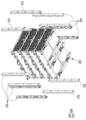
도 3은 본 발명의 일 실시예에 따른 복수의 전지 모듈들이 복수의 세로 각 관들과 함께 적층되는 모습을 나타낸 사시도이다.
도 4는 본 발명의 일 실시예에 따른 제1 세로 각 관의 상면도(a), 사시도(b), 측면도(c)이다.
도 5는 본 발명의 일 실시예에 따른 제2 세로 각 관의 상면도(a), 사시도(b), 측면도(c)이다.
도 6은 본 발명의 일 실시예에 따른 제3 세로 각 관의 상면도(a), 사시도(b), 측면도(c)이다.
도 7은 본 발명의 일 실시예에 따른 제4 세로 각 관의 상면도(a), 사시도(b), 측면도(c)이다.
도 8은 본 발명의 일 실시예에 따른 전지 모듈 적층체에 세로 각 관들이 결합된 모습을 나타낸 도면이다.
도 9는 도 8의 구성 및 본 발명의 일 실시예에 따른 복수의 수직 각 관을 나타낸 도면이다.
도 10은 본 발명의 일 실시예에 따른 제1 수직 각 관의 상면도(a), 사시도(b), 측면도(c)이다.
도 11은 본 발명의 일 실시예에 따른 제2 수직 각 관의 상면도(a), 사시도(b), 측면도(c)이다.
도 12는 도 9의 전지 모듈 적층체에 복수의 수직 각 관이 결합된 모습을 나타낸 도면이다.
도 13은 도 12의 구성 및 본 발명의 일 실시예에 따른 가로 각관들을 나타낸 도면이다.
도 14는 본 발명의 일 실시예에 따른 가로 각 관의 상면도(a), 사시도(b), 측면도(c)이다.
도 15는 도 12의 전지 모듈 적층체에 복수의 가로 각 관들이 결합된 모습을 나타낸 도면이다.
도 16은 본 발명의 일 실시예에 따른 BMS, BDU가 전지 모듈 적층체에 결합된 모습을 나타낸 도면이다.
도 17은 도 16의 정면도이다.
도 18은 도 16의 후면도이다.
도 19는 도 16의 상면도이다.
도 20은 도 19의 A-A'부분을 나타낸 단면도이다.
도 21은 본 발명의 일 실시예에 따른 전지 모듈 적층체, 상하부 케이스 및 브라켓을 나타낸 도면이다.
도 22는 본 발명의 일 실시예에 따른 하부 케이스를 나타낸 도면이다.
도 23은 본 발명의 일 실시예에 따른 상하부 케이스가 조립된 모습을 나타낸 도면이다.FIG. 1 is a perspective view showing the first and second vertical tubes and the heat sink insulator according to one embodiment of the present invention.
FIG. 2 is a perspective view showing the assembled configuration of FIG. 1 and the heat sink and battery modules according to one embodiment of the present invention.
FIG. 3 is a perspective view showing a plurality of battery modules stacked together with a plurality of vertical tubes according to one embodiment of the present invention.
FIG. 4 is a top view (a), a perspective view (b), and a side view (c) of a first vertical angle pipe according to one embodiment of the present invention.
FIG. 5 is a top view (a), a perspective view (b), and a side view (c) of a second vertical angle pipe according to one embodiment of the present invention.
FIG. 6 is a top view (a), a perspective view (b), and a side view (c) of a third vertical angle pipe according to one embodiment of the present invention.
FIG. 7 is a top view (a), a perspective view (b), and a side view (c) of a fourth vertical angle pipe according to one embodiment of the present invention.
FIG. 8 is a drawing showing a state in which vertical tubes are combined in a battery module stack according to one embodiment of the present invention.
FIG. 9 is a drawing showing a configuration of FIG. 8 and a plurality of vertical angle pipes according to one embodiment of the present invention.
FIG. 10 is a top view (a), a perspective view (b), and a side view (c) of a first vertical angle pipe according to one embodiment of the present invention.
FIG. 11 is a top view (a), a perspective view (b), and a side view (c) of a second vertical angle pipe according to one embodiment of the present invention.
Figure 12 is a drawing showing a plurality of vertical angle tubes combined in the battery module stack of Figure 9.
FIG. 13 is a drawing showing the configuration of FIG. 12 and horizontal sections according to one embodiment of the present invention.
FIG. 14 is a top view (a), a perspective view (b), and a side view (c) of a horizontal pipe according to one embodiment of the present invention.
Figure 15 is a drawing showing a plurality of horizontal angle tubes combined in the battery module stack of Figure 12.
FIG. 16 is a drawing showing a BMS and BDU combined with a battery module stack according to one embodiment of the present invention.
Figure 17 is a front view of Figure 16.
Fig. 18 is a rear view of Fig. 16.
Figure 19 is a top view of Figure 16.
Fig. 20 is a cross-sectional view showing the A-A' portion of Fig. 19.
FIG. 21 is a drawing showing a battery module stack, upper and lower cases, and a bracket according to one embodiment of the present invention.
FIG. 22 is a drawing showing a lower case according to one embodiment of the present invention.
Figure 23 is a drawing showing the assembled upper and lower cases according to one embodiment of the present invention.
이하에서 설명되는 실시 예는 발명의 이해를 돕기 위하여 예시적으로 나타낸 것이며, 본 발명은 여기서 설명되는 실시 예와 다르게 다양하게 변형되어 실시될 수 있음이 이해되어야 할 것이다. 다만, 본 발명을 설명함에 있어서 관련된 공지 기능 혹은 구성요소에 대한 구체적인 설명이 본 발명의 요지를 불필요하게 흐릴 수 있다고 판단되는 경우 그 상세한 설명 및 구체적인 도시를 생략한다. 또한, 첨부된 도면은 발명의 이해를 돕기 위하여 실제 축척대로 도시된 것이 아니라 일부 구성요소의 치수가 과장되게 도시될 수 있다.The embodiments described below are provided as examples to help understand the invention, and it should be understood that the invention may be implemented in various ways different from the embodiments described herein. However, when describing the invention, if it is determined that a specific description of a related known function or component may unnecessarily obscure the gist of the invention, the detailed description and specific illustration thereof will be omitted. In addition, the attached drawings are not drawn to scale to help understand the invention, and the dimensions of some components may be exaggerated.
본 출원에서 사용되는 제1, 제2 용어는 다양한 구성요소들을 설명하는데 사용될 수 있지만, 구성요소들은 용어들에 의해 한정되어서는 안 된다. 용어들은 하나의 구성요소를 다른 구성요소로부터 구별하는 목적으로만 사용된다.The first and second terms used in this application may be used to describe various components, but the components should not be limited by the terms. The terms are used only for the purpose of distinguishing one component from another.
또한, 본 출원에서 사용되는 용어는 단지 특정한 실시 예를 설명하기 위해 사용된 것으로, 권리범위를 한정하려는 의도가 아니다. 단수의 표현은 문맥상 명백하게 다르게 뜻하지 않는 한, 복수의 표현을 포함한다. 본 출원에서 "포함하다", "이루어진다" 또는 "구성되다" 등의 용어는 명세서상 기재된 특징, 숫자, 단계, 동작, 구성요소, 부품 또는 이들의 조합한 것이 존재함을 지정하려는 것이지, 하나 또는 그 이상의 다른 특징들이나 숫자, 단계, 동작, 구성요소, 부품 또는 이들의 조합한 것들의 존재 또는 부가 가능성을 미리 배제하지 않는 것으로 이해되어야 한다.In addition, the terminology used in this application is only used to describe specific embodiments and is not intended to limit the scope of the rights. The singular expression includes the plural expression unless the context clearly indicates otherwise. It should be understood that the terms "comprises," "consists of," or "consists of" in this application are intended to specify the presence of a feature, number, step, operation, component, part, or combination thereof described in the specification, but do not exclude in advance the possibility of the presence or addition of one or more other features, numbers, steps, operations, components, parts, or combinations thereof.
후술할 발명의 내용에 대응한 도면의 순서는 본 발명의 일 실시예에 따른 전지팩의 조립 과정을 순서대로 보여주고 있다. 또한 후술할 본 발명을 형성하는 구성들의 배치 방향에 대하여, 대표도인 도 15에 도시된 전후 방향, 좌우 방향, 상하 방향에 대응하는 방향으로 기술한다. 상기 방향들의 기준은 본 발명의 전지 모듈들의 배치 방향에 따른 것이다.The order of the drawings corresponding to the content of the invention described below sequentially shows the assembly process of a battery pack according to one embodiment of the present invention. In addition, the arrangement direction of the components forming the present invention described below is described in the direction corresponding to the front-back direction, left-right direction, and up-down direction shown in the representative drawing, Fig. 15. The reference of the above directions is based on the arrangement direction of the battery modules of the present invention.
이하, 도 1 내지 도 8을 주로 참조하며, 본 발명의 일 실시예에 따른 세로 각 관 및 세로 각 관과 연결된 주변 구성에 대해 설명한다.Hereinafter, with reference mainly to FIGS. 1 to 8, a description will be given of each vertical pipe and a peripheral configuration connected to each vertical pipe according to one embodiment of the present invention.
도 1은 본 발명의 일 실시예에 따른 제1,2 세로 각 관 및 히트 싱크 인설레이터를 나타낸 사시도이다. 도 2는 조립된 도 1의 구성 및 본 발명의 일 실시예에 따른 히트 싱크와 전지 모듈들을 나타낸 사시도이다. 도 3은 본 발명의 일 실시예에 따른 복수의 전지 모듈들이 복수의 세로 각 관들과 함께 적층되는 모습을 나타낸 사시도이다. 도 4는 본 발명의 일 실시예에 따른 제1 세로 각 관의 상면도(a), 사시도(b), 측면도(c)이다. 도 5는 본 발명의 일 실시예에 따른 제2 세로 각 관의 상면도(a), 사시도(b), 측면도(c)이다. 도 6은 본 발명의 일 실시예에 따른 제3 세로 각 관의 상면도(a), 사시도(b), 측면도(c)이다. 도 7은 본 발명의 일 실시예에 따른 제4 세로 각 관의 상면도(a), 사시도(b), 측면도(c)이다. 도 8은 본 발명의 일 실시예에 따른 전지 모듈 적층체에 세로 각 관들이 결합된 모습을 나타낸 도면이다.FIG. 1 is a perspective view showing first and second vertical angle pipes and a heat sink insulator according to an embodiment of the present invention. FIG. 2 is a perspective view showing the assembled configuration of FIG. 1 and the heat sink and battery modules according to an embodiment of the present invention. FIG. 3 is a perspective view showing a state where a plurality of battery modules are stacked together with a plurality of vertical angle pipes according to an embodiment of the present invention. FIG. 4 is a top view (a), a perspective view (b), and a side view (c) of a first vertical angle pipe according to an embodiment of the present invention. FIG. 5 is a top view (a), a perspective view (b), and a side view (c) of a second vertical angle pipe according to an embodiment of the present invention. FIG. 6 is a top view (a), a perspective view (b), and a side view (c) of a third vertical angle pipe according to an embodiment of the present invention. FIG. 7 is a top view (a), a perspective view (b), and a side view (c) of a fourth vertical angle pipe according to an embodiment of the present invention. FIG. 8 is a drawing showing a state in which vertical tubes are combined in a battery module stack according to one embodiment of the present invention.
먼저, 도 8을 참조하여, 복수의 세로 각 관들의 전반적인 배치를 살펴본다. First, referring to Figure 8, the overall arrangement of the plurality of vertical tubes is examined.
복수의 세로 각 관(300)은, 적층된 전지 모듈(210)의 전후 방향으로 형성되고, 전지 모듈 적층체(200)에 마운팅되며, 적층된 전지 모듈(210)들 사이, 최상단 및 최하단에서 좌우 방향으로 형성된 전지 모듈(210)들 모두와 결합하도록 상하 방향으로 적층 배치된다.A plurality of vertical tubes (300) are formed in the front-back direction of the stacked battery modules (210), mounted on the battery module stack (200), and arranged in a vertical stack so as to be combined with all of the battery modules (210) formed in the left-right direction between the stacked battery modules (210) at the top and bottom.
이러한 전지 모듈 적층체(200)의 복수의 전지 모듈(210)들을 고정하는 복수의 세로 각 관(300)은, 적층된 전지 모듈(210)들의 최하단 양끝에 형성된 복수의 제1 세로 각 관(310), 적층된 전지 모듈(210)들의 최하단에서, 복수의 제1 세로 각 관(310) 사이에 형성된 적어도 하나의 제2 세로 각 관(320), 적층된 전지 모듈(210)들의 최상단 및 적층된 전지 모듈들의 사이에 형성된 복수의 세로 각 관(300) 중 양 끝에 형성된 복수의 제3 세로 각 관(330), 적층된 전지 모듈들의 최상단에 형성된 복수의 제3 세로 각 관(330)을 제외한 복수의 제3 세로 각 관(330)의 사이에 형성된 적어도 하나의 제4 세로 각 관(340)을 포함할 수 있다.A plurality of vertical angle tubes (300) for fixing a plurality of battery modules (210) of the battery module stack (200) may include a plurality of first vertical angle tubes (310) formed at both ends of the lowest portion of the stacked battery modules (210), at least one second vertical angle tube (320) formed between the plurality of first vertical angle tubes (310) at the lowest portion of the stacked battery modules (210), a plurality of third vertical angle tubes (330) formed at both ends of the plurality of vertical angle tubes (300) formed at the uppermost portion of the stacked battery modules (210) and between the stacked battery modules, and at least one fourth vertical angle tube (340) formed between the plurality of third vertical angle tubes (330) excluding the plurality of third vertical angle tubes (330) formed at the uppermost portion of the stacked battery modules.
본 발명의 일 실시예에 따르면, 제2 세로 각 관(320)은 전지 모듈 적층체(200)의 양끝 하단에 위치한 제1 세로 각 관(310)의 사이에서, 양끝의 제1 세로 각 관(310)들과 동일한 간격을 유지하는 두 개의 제2 세로 각 관(320)으로 배치될 수 있다.According to one embodiment of the present invention, the second vertical angle tube (320) may be arranged between the first vertical angle tubes (310) located at the bottom of both ends of the battery module stack (200), with two second vertical angle tubes (320) maintaining the same spacing as the first vertical angle tubes (310) at both ends.
또한 본 발명의 일 실시예에 따르면, 제 4 세로 각 관(340)은 전지 모듈 적층체(200)의 양끝에 형성된 복수의 제3 세로 각 관(330) 중 동일한 평면상에 위치하는 두개의 제3 세로 각 관(330)의 사이에서, 양끝의 제 3 세로 각 관(330)들과 동일한 간격을 유지하는 두 개의 제 4 세로 각 관(340)으로 배치될 수 있다. 또한 적층된 전지 모듈(210)들 각각의 하단 양끝에 위치하는 복수의 제3 세로 각 관(330)의 상하 방향 적층 위치에 대응하도록 제 3 세로 각 관(330)의 사이에 제 4 세로 각 관(340)이 두개씩 상하 방향으로 적층 배치될 수 있다.In addition, according to one embodiment of the present invention, the fourth vertical angle pipes (340) may be arranged between two third vertical angle pipes (330) formed at both ends of the battery module stack (200) and positioned on the same plane, with two fourth vertical angle pipes (340) maintaining the same spacing as the third vertical angle pipes (330) at both ends. In addition, two fourth vertical angle pipes (340) may be arranged in the vertical direction between the third vertical angle pipes (330) so as to correspond to the vertical stacking positions of the plurality of third vertical angle pipes (330) positioned at both ends of the lower ends of each of the stacked battery modules (210).
본 발명의 일 실시예에 따르면, 전지 모듈(210)은 상하 방향으로 4단으로 적층 배치되며, 4단 각각의 전지 모듈(210)층의 양 끝에 제3 세로 각 관(330)들과, 제3 세로 각 관(330)들의 사이에서 제3 세로 각 관(330)들과 일정한 간격을 유지하도록 배치된 두 개의 제4 세로 각 관(340)이 4단으로 적층 배치될 수 있다.According to one embodiment of the present invention, the battery modules (210) are stacked in four stages in the vertical direction, and third vertical angle pipes (330) may be stacked in four stages at both ends of each battery module (210) layer in each of the four stages, and two fourth vertical angle pipes (340) may be stacked in four stages between the third vertical angle pipes (330) and arranged to maintain a constant distance from the third vertical angle pipes (330).
이하, 도 1 및 도 2를 주로 참조하여, 본 발명의 일 실시예에 따른 히트 싱크(600) 및 히트 싱크 인설레이터(610)의 배치에 대해 설명한다.Hereinafter, with reference primarily to FIGS. 1 and 2, the arrangement of a heat sink (600) and a heat sink insulator (610) according to one embodiment of the present invention will be described.
도 1 및 도 2를 참조하면, 본 발명의 일 실시예에 따른 전지 모듈(210)은, 복수의 전지 모듈(210)들이 수평 방향으로 결합될 수 있다. 본 발명의 일 실시예에 따르면, 두 전지 모듈(210)이, 전지 모듈(210)의 길이 방향과 수직인 방향으로 결합할 수 있다. 전술할 바와 같이, 두 전지 모듈(210)이 상하 방향으로 적층 배치되어 전지 모듈 적층체(200)를 구성할 수 있다.Referring to FIGS. 1 and 2, a battery module (210) according to one embodiment of the present invention may be configured such that a plurality of battery modules (210) are coupled in a horizontal direction. According to one embodiment of the present invention, two battery modules (210) may be coupled in a direction perpendicular to the longitudinal direction of the battery modules (210). As described above, two battery modules (210) may be stacked in a vertical direction to form a battery module stack (200).
도 2를 참조하면, 본 발명의 일 실시예에 따른 전지 모듈(210)들 하단에는 히트 싱크(600)가 배치될 수 있다. 또한 히트 싱크(600)의 하단에는 히트 싱크 인설레이터(610) 및 히트 싱크 인설레이터(610)를 고정하는 제1 세로 각 관(310)이 배치될 수 있다.Referring to FIG. 2, a heat sink (600) may be placed at the bottom of battery modules (210) according to one embodiment of the present invention. In addition, a heat sink insulator (610) and a first vertical angle tube (310) for fixing the heat sink insulator (610) may be placed at the bottom of the heat sink (600).
히트 싱크(600)는 전지 모듈(210)들과 복수의 세로 각 관(300) 사이에 형성될 수 있다. 본 발명에 따른 전지 모듈은 간접 수냉식 모듈로서, 전지 모듈 하측에 위치한 히트 싱크(600)를 통해 전지 모듈에서 발생하는 열을 냉각시킬 수 있다. 따라서 히트 싱크(600)는 전지 모듈(210)들의 하단에 밀착 배치될 수 있다.A heat sink (600) may be formed between the battery modules (210) and a plurality of vertical tubes (300). The battery module according to the present invention is an indirect water-cooled module, and can cool the heat generated in the battery module through the heat sink (600) located at the bottom of the battery module. Therefore, the heat sink (600) may be placed in close contact with the bottom of the battery modules (210).
히트 싱크(600)의 양단에는 연결부(601)가 형성될 수 있다. 도 2에 도시된대로, 연결부(601)는 제1 세로 각 관(310)에 형성된 연결부(311)와 결합할 수 있다. 본 발명의 일 실시예에 따르면, 연결부(601)는 히트 싱크(600)의 양단에 두개씩 형성될 수 있으며, 제1 세로 각 관(310)에 형성된 연결부(311) 또한 양측에 두개로 형성되어, 히트 싱크(600)의 연결부(601)와 제1 세로 각 관(310)의 연결부(311)가 서로 결합할 수 있다. 이때, 히트 싱크(600)의 평면 내의 유동을 억제하기 위하여, 제1 세로 각 관(310)의 연결부(311)와 히트 싱크(600)의 연결부(601)는 볼트 및 너트로 체결 고정될 수 있다.A connecting portion (601) may be formed at both ends of the heat sink (600). As illustrated in FIG. 2, the connecting portion (601) may be coupled with a connecting portion (311) formed at the first vertical angle pipe (310). According to one embodiment of the present invention, two connecting portions (601) may be formed at each end of the heat sink (600), and two connecting portions (311) formed at the first vertical angle pipe (310) may also be formed at each end, so that the connecting portion (601) of the heat sink (600) and the connecting portion (311) of the first vertical angle pipe (310) may be coupled to each other. At this time, in order to suppress flow within the plane of the heat sink (600), the connecting portion (311) of the first vertical angle pipe (310) and the connecting portion (601) of the heat sink (600) may be fastened together with bolts and nuts.
본 발명의 일 실시예에 따르면, 두 전지 모듈(210)이 상하 방향으로 적층 배치되며, 히트 싱크(600)는 각 층에 형성된 두 전지 모듈(210)의 하단에 각각 배치될 수 있다. 따라서 상하 방향으로 적층된 각각의 전지 모듈(210)들 하단에 히트 싱크(600)들이 밀착되도록 배치되어 모든 전지 모듈(210)들에서 발생하는 열을 냉각시킬 수 있다.According to one embodiment of the present invention, two battery modules (210) are stacked in a vertical direction, and heat sinks (600) can be respectively placed at the bottoms of the two battery modules (210) formed in each layer. Accordingly, heat sinks (600) are placed in close contact with the bottoms of each of the battery modules (210) stacked in a vertical direction, thereby cooling the heat generated from all of the battery modules (210).
도 2에 도시된 전지 모듈(210)들의 하단에 형성된 히트 싱크(600), 제1 세로 각 관(310)의 구성은, 도 3에 도시된 바와 같이 상측으로 적층 배치되는 전지 모듈(210) 구조에 동일하게 적용될 수 있다. 다만 상측으로 적층되는 구조에서는, 도 3에 도시된 바와 같이 제1 세로 각 관(310)의 위치에 제3 세로 각 관(330)이 형성될 수 있다.The configuration of the heat sink (600) and the first vertical angle tube (310) formed at the bottom of the battery modules (210) illustrated in FIG. 2 can be applied equally to the battery module (210) structure that is stacked upward as illustrated in FIG. 3. However, in the structure that is stacked upward, the third vertical angle tube (330) can be formed at the location of the first vertical angle tube (310) as illustrated in FIG. 3.
따라서, 최하단에 형성된 전지 모듈(210)들 하측에 형성된 히트 싱크(600) 외에도, 상측으로 적층 배치된 전지 모듈(210)들 각각의 하측에 형성된 히트 싱크(600)들의 양단에도 도 2에 도시된 바와 같은 연결부(601)가 형성되어 있고, 이때 연결부(601)는 도 6에 도시된 제3 세로 각 관(330)에 형성된 연결부(331)와 결합할 수 있다. 본 발명의 일 실시예에 따르면, 최하단 전지 모듈(210)들보다 상측에 형성된 히트 싱크(600)들의 연결부(601) 또한 마찬가지로 최하단 전지 모듈(210)의 하측에 형성된 히트 싱크(600)와 동일한 구조로 형성되며, 제3 세로 각 관(330)에 형성된 연결부(331) 또한 양측에 두개로 형성되어, 히트 싱크(600)의 연결부(601)와 제3 세로 각 관(330)의 연결부(331)가 각층마다 서로 결합할 수 있다. 마찬가지로 히트 싱크(600)의 평면 내의 유동을 억제하기 위하여, 제3 세로 각 관(330)의 연결부(331)와 히트 싱크(600)의 연결부(601)들은 볼트 및 너트로 체결 고정될 수 있다.Accordingly, in addition to the heat sink (600) formed on the lower side of the battery modules (210) formed at the lowest level, a connecting portion (601) as illustrated in FIG. 2 is formed on both ends of the heat sinks (600) formed on the lower side of each of the battery modules (210) stacked upwards, and at this time, the connecting portion (601) can be combined with the connecting portion (331) formed on the third vertical angle pipe (330) illustrated in FIG. 6. According to one embodiment of the present invention, the connection portions (601) of the heat sinks (600) formed above the lowermost battery modules (210) are also formed with the same structure as the heat sinks (600) formed below the lowermost battery modules (210), and the connection portions (331) formed in the third vertical angle pipe (330) are also formed in two on both sides, so that the connection portions (601) of the heat sinks (600) and the connection portions (331) of the third vertical angle pipe (330) can be coupled to each other at each layer. Similarly, in order to suppress flow within the plane of the heat sink (600), the connection portions (331) of the third vertical angle pipe (330) and the connection portions (601) of the heat sinks (600) can be fastened with bolts and nuts.
히트 싱크(600)의 중앙부 하측에는, 제 2 세로 각 관(320)이 배치될 수 있다. 도 5를 참조하면, 제2 세로 각 관(320)의 가운데 부분에는 절개부(323)가 형성되고, 히트 싱크(600)의 중앙부는 절개부(323)에 삽입되어 제2 세로 각 관(320)에 의해 고정될 수 있다.A second vertical angle tube (320) may be arranged at the lower center of the heat sink (600). Referring to FIG. 5, a cutout (323) is formed at the center of the second vertical angle tube (320), and the center of the heat sink (600) may be inserted into the cutout (323) and fixed by the second vertical angle tube (320).
도 2에 도시된 히트 싱크(600) 및 제 2 세로 각 관(320)의 구성은 도 3에 도시된 바와 같이 상측으로 적층 배치되는 전지 모듈(210) 구조에 동일하게 적용될 수 있다. 다만 상측으로 적층되는 구조에서는, 도 3에 도시된 바와 같이 제2 세로 각 관(320)의 위치에 제4 세로 각 관(340)이 형성될 수 있다.The configuration of the heat sink (600) and the second vertical angle tube (320) illustrated in FIG. 2 can be applied equally to the battery module (210) structure that is stacked upward as illustrated in FIG. 3. However, in the structure that is stacked upward, the fourth vertical angle tube (340) can be formed at the location of the second vertical angle tube (320) as illustrated in FIG. 3.
히트 싱크 인설레이터(610)는 히트 싱크(600)와 히트 싱크(600)의 하측에 위치한 전지 모듈(210)들 사이에 배치되어, 히트 싱크(600)를 전지 모듈(610)에 밀착시킬 수 있다. 히트 싱크 인설레이터(610)는 전기적 절연 및 열적 단열 성능이 우수한 플라스틱으로 형성될 수 있다.A heat sink insulator (610) is placed between the heat sink (600) and the battery modules (210) located on the lower side of the heat sink (600), so as to allow the heat sink (600) to be pressed against the battery modules (610). The heat sink insulator (610) can be formed of a plastic having excellent electrical insulation and thermal insulation performance.
본 발명의 일 실시예에 따른 복수의 각 관들은, 볼트 너트 조립을 위한 일정 정도의 두께가 요구되며, 전지 모듈들의 적층 높이를 최소화하기 위해 히트 싱크를 보다 얇게 형성하는 과정에서, 복수의 각 관보다 히트 싱크의 두께가 더 얇아질 수 있다. According to one embodiment of the present invention, a plurality of individual tubes require a certain thickness for bolt nut assembly, and in the process of forming the heat sink thinner to minimize the stacking height of the battery modules, the thickness of the heat sink may be thinner than that of the plurality of individual tubes.
이와 같이 각 관의 두께보다 히트 싱크의 두께가 더 얇아짐에 따라, 전지 모듈들과 히트 싱크 사이에 간격이 생길 수 있는바, 전지 모듈 하단과 히트 싱크 사이의 간격을 해소하기 위해, 히트 싱크 인설레이터(610)를 히트 싱크(600)의 하단에 배치하여 히트 싱크(600)를 전지 모듈(210)들에 밀착시킬 수 있게 되었다.As the thickness of the heat sink becomes thinner than the thickness of each tube, a gap may be created between the battery modules and the heat sink. To eliminate the gap between the bottom of the battery module and the heat sink, a heat sink insulator (610) is placed at the bottom of the heat sink (600) so that the heat sink (600) can be brought into close contact with the battery modules (210).
본 발명의 일 실시예에 따르면, 히트 싱크(600)의 두께는 써말패드를 포함하여 10mm이며, 히트 싱크 인설레이터(610)의 두께는 15mm이고 각 관의 두께는 25mm이다. 이를 통해, 히트 싱크(600)와 히트 싱크 인설레이터(610)를 통해 각 관의 두께가 형성하는 공간을 채울 수 있음을 알 수 있다.According to one embodiment of the present invention, the thickness of the heat sink (600) is 10 mm including the thermal pad, the thickness of the heat sink insulator (610) is 15 mm, and the thickness of each tube is 25 mm. Through this, it can be seen that the space formed by the thickness of each tube can be filled through the heat sink (600) and the heat sink insulator (610).
히트 싱크 인설레이터(610)는, 가운데에 형성된 제1 히트 싱크 인설레이터(611) 및 양측에 형성된 제2,3 히트 싱크 인설레이터(612, 613)를 포함할 수 있다. 제1 히트 싱크 인설레이터(611)는 복수의 제2 세로 각 관(320)의 사이에 형성될 수 있고, 제2,3 히트 싱크 인설레이터(612, 613)는 복수의 제2 세로 각 관(320)과 양 끝의 제1 세로 각 관(310) 사이에 형성될 수 있다.The heat sink insulator (610) may include a first heat sink insulator (611) formed in the center and second and third heat sink insulators (612, 613) formed on both sides. The first heat sink insulator (611) may be formed between a plurality of second vertical angle tubes (320), and the second and third heat sink insulators (612, 613) may be formed between a plurality of second vertical angle tubes (320) and the first vertical angle tubes (310) on both ends.
본 발명의 일 실시예에 따르면, 도 2에 도시된 바와 같이, 제1 히트 싱크 인설레이터(611)는 두개의 제2 세로 각 관(320)의 사이에 형성될 수 있고, 제2,3 히트 싱크 인설레이터(612, 613)는 전지 모듈 적층체(200)의 양끝에 형성된 제1 세로 각 관(310)과, 제1 세로 각 관(310)들 각각과 가장 인접한 제2 세로 각 관(320)사이에 형성될 수 있다.According to one embodiment of the present invention, as illustrated in FIG. 2, the first heat sink insulator (611) may be formed between two second vertical angle tubes (320), and the second and third heat sink insulators (612, 613) may be formed between the first vertical angle tubes (310) formed at both ends of the battery module stack (200) and the second vertical angle tubes (320) that are closest to each of the first vertical angle tubes (310).
도 2에 도시된 히트 싱크(600)의 하단에 형성된 히트 싱크 인설레이터(610) 및 제 1,2 세로 각 관(310, 320)의 구성은, 도 3에 도시된 바와 같이 상측으로 적층 배치되는 전지 모듈(210) 구조에 동일하게 적용될 수 있다. 다만 상측으로 적층되는 구조에서는, 도 3에 도시된 바와 같이 제1 세로 각 관(310)의 위치에 제3 세로 각 관(330)이, 제2 세로 각 관(320)의 위치에 제4 세로 각 관(340)이 형성될 수 있다.The configuration of the heat sink insulator (610) formed at the bottom of the heat sink (600) illustrated in FIG. 2 and the first and second vertical angle tubes (310, 320) can be applied to the battery module (210) structure that is stacked upward as illustrated in FIG. 3. However, in the structure that is stacked upward, the third vertical angle tube (330) can be formed at the position of the first vertical angle tube (310) as illustrated in FIG. 3, and the fourth vertical angle tube (340) can be formed at the position of the second vertical angle tube (320).
보다 상세하게는, 도 3에 도시된 바와 같이, 제1 히트 싱크 인설레이터(611)는 두개의 제4 세로 각 관(340)의 사이에 형성될 수 있고, 제2,3 히트 싱크 인설레이터(612, 613)는 전지 모듈 적층체(200)의 양끝에 형성된 제3 세로 각 관(330)과, 제3 세로 각 관(330) 각각과 가장 인접한 제4 세로 각 관(340)사이에 형성될 수 있다.More specifically, as illustrated in FIG. 3, the first heat sink insulator (611) may be formed between two fourth vertical angle tubes (340), and the second and third heat sink insulators (612, 613) may be formed between the third vertical angle tubes (330) formed at both ends of the battery module stack (200) and the fourth vertical angle tube (340) most adjacent to each of the third vertical angle tubes (330).
히트 싱크 인설레이터(610)의 일단에는 집게부(610a)가 형성되어, 후술할 냉각수 파이프를 고정시킬 수 있다. 히트 싱크 인설레이터(610), 히트 싱크(600) 및 제1,3 세로 각 관(310, 330)의 배치 구조는 도 20에 도시된 단면으로도 확인할 수 있다.A clamp part (610a) is formed at one end of the heat sink insulator (610) to fix a cooling water pipe, which will be described later. The arrangement structure of the heat sink insulator (610), the heat sink (600), and the first and third vertical pipes (310, 330) can also be confirmed in the cross-section shown in Fig. 20.
이하, 도 4 내지 도 7을 주로 참조하여, 본 발명의 일 실시예에 따른 제1 내지 제4 세로 각 관의 구조에 대해 설명한다.Hereinafter, with reference mainly to FIGS. 4 to 7, the structure of each of the first to fourth vertical tubes according to one embodiment of the present invention will be described.
제1 세로 각 관(310)은, 도 4를 참조하면, 히트 싱크(600)의 연결부(601)와 결합하는 연결부(311), 제1 수직 각 관(410)과 연결되는 제1 수직 각 관 연결부(312, 313), 제2 수직 각 관(420)과 연결되는 제2 수직 각 관 연결부(314, 315) 및 전지 모듈 적층체(200) 전체를 지지하고 동시에 도 22에 도시된 하부 케이스(120)의 세로 각 관 연결부(122)와 결합하는 받침부(316)를 포함할 수 있다.Referring to FIG. 4, the first vertical angle pipe (310) may include a connection part (311) that is coupled with a connection part (601) of a heat sink (600), a first vertical angle pipe connection part (312, 313) that is coupled with the first vertical angle pipe (410), a second vertical angle pipe connection part (314, 315) that is coupled with the second vertical angle pipe (420), and a support part (316) that supports the entire battery module stack (200) and is coupled with the vertical angle pipe connection part (122) of the lower case (120) illustrated in FIG. 22.
본 발명의 다른 실시예에 의하면, 제1 세로 각 관(310)은 제1-1 수직 각 관 연결부(317, 318)을 제1 수직 각 관 연결부(312, 313)와 함께 포함할 수 있다. 이를 통해, 도 12에 도시된 바와 같이, 제1 수직 각 관(410)이 제1 수직 각 관 연결부(312, 313)와 각각 결합할 수도 있고, 도 18에 도시된 바와 같이, 제1 수직 각 관(410)이 제1-1 수직 각 관 연결부(317, 318)과 결합할 수 있다.According to another embodiment of the present invention, the first vertical angle pipe (310) may include the first-first vertical angle pipe connection portion (317, 318) together with the first vertical angle pipe connection portion (312, 313). Accordingly, as illustrated in FIG. 12, the first vertical angle pipe (410) may be connected to the first vertical angle pipe connection portion (312, 313), respectively, and as illustrated in FIG. 18, the first vertical angle pipe (410) may be connected to the first-first vertical angle pipe connection portion (317, 318).
연결부(311)는 제1 세로 각 관(310)의 양측에 형성된 홈에 각각 형성될 수 있다. 상기 홈은 각 관의 양측의 이웃한 두면이 제거되며 형성된 공간으로, 연결부(311)는 상기 홈의 제거되지 않은 두 면 중 하나의 면 상에 형성되어, 상기 홈으로 삽입되는 히트 싱크(600)의 연결부(601)와 결합할 수 있다. 양측에 형성된 연결부(311)는 평행하게 형성될 수 있다.The connecting portion (311) may be formed in each groove formed on both sides of the first vertical tube (310). The groove is a space formed by removing two adjacent sides of each tube, and the connecting portion (311) is formed on one of the two unremoved sides of the groove, so that it may be combined with the connecting portion (601) of the heat sink (600) inserted into the groove. The connecting portions (311) formed on both sides may be formed in parallel.
제1 수직 각 관 연결부(312, 313) 및 제1-1 수직 각 관 연결부(317, 318)는, 상기 홈에서 연결부(311)가 형성되지 않은 나머지 면 상에 형성될 수 있다. 제1 수직 각 관 연결부(312, 313) 및 제1-1 수직 각 관 연결부(317, 318)는 각각 평행하게 형성될 수 있다. 제1 수직 각 관 연결부(312)는 제1-1 수직 각 관 연결부(317)보다 바깥쪽에 형성될 수 있고, 제1 수직 각 관 연결부(313) 또한 제1-1 수직 각 관 연결부(318)보다 바깥쪽에 형성될 수 있다.The first vertical angle pipe connection portions (312, 313) and the 1-1st vertical angle pipe connection portions (317, 318) may be formed on the remaining surface of the groove where the connection portion (311) is not formed. The first vertical angle pipe connection portions (312, 313) and the 1-1st vertical angle pipe connection portions (317, 318) may be formed in parallel, respectively. The first vertical angle pipe connection portion (312) may be formed on the outside relative to the 1-1st vertical angle pipe connection portion (317), and the first vertical angle pipe connection portion (313) may also be formed on the outside relative to the 1-1st vertical angle pipe connection portion (318).
제 2 수직 각 관 연결부(314, 315)는 제1 세로 각 관(310)의 일면 양단에 형성되어, 제2 수직 각 관(420)과 각각 결합할 수 있다.The second vertical angle pipe connecting portions (314, 315) are formed at both ends of one side of the first vertical angle pipe (310) and can be connected to the second vertical angle pipe (420), respectively.
제1 세로 각 관(310)의 양단은 사선 방향으로 깎아지게 형성될 수 있다. 제1 세로 각 관(310)의 일단에 형성된 사선 방향과 타단에 형성된 사선 방향은 서로 대칭으로 형성될 수 있다. 제1 세로 각 관(310)의 양끝단 중 일면은 제1 세로 각 관(310)의 길이 방향과 수직으로 돌출된 받침부(316)를 형성할 수 있다.The two ends of the first vertical angle pipe (310) may be formed to be cut diagonally. The diagonal direction formed at one end of the first vertical angle pipe (310) and the diagonal direction formed at the other end may be formed symmetrically to each other. One side of the two ends of the first vertical angle pipe (310) may form a support portion (316) that protrudes perpendicularly to the longitudinal direction of the first vertical angle pipe (310).
제2 세로 각 관(320)은, 도 5를 참조하면, 제2 수직 각 관(420)과 연결되는 제2 수직 각 관 연결부(321, 322), 히트 싱크(600)가 삽입되는 절개부(323) 및 전지 모듈 적층체(200) 전체를 지지하고 동시에 도 22에 도시된 하부 케이스(120)의 세로 각 관 연결부(122)와 결합하는 받침부(324)를 포함할 수 있다.The second vertical angle pipe (320), referring to FIG. 5, may include a second vertical angle pipe connection portion (321, 322) connected to the second vertical angle pipe (420), a cut portion (323) into which a heat sink (600) is inserted, and a support portion (324) that supports the entire battery module stack (200) and is simultaneously coupled with the vertical angle pipe connection portion (122) of the lower case (120) illustrated in FIG. 22.
제2 수직 각 관 연결부(321, 322)는, 제2 세로 각 관(320)의 일면 양단에 형성되어, 도 12에 도시된 바와 같이 제2 수직 각 관(420)들과 결합할 수 있다. 절개부(323)는 제2 세로 각 관(320)의 가운데에 형성되어, 절개된 공간에 판형의 히트 싱크(600)의 일부가 삽입될 수 있다.The second vertical angle pipe connecting portions (321, 322) are formed at both ends of one side of the second vertical angle pipe (320) and can be combined with the second vertical angle pipes (420) as shown in Fig. 12. The cut portion (323) is formed in the center of the second vertical angle pipe (320) and a part of a plate-shaped heat sink (600) can be inserted into the cut space.
제2 세로 각 관(320)의 양단은 사선 방향으로 깎아지게 형성될 수 있다. 제2 세로 각 관(320)의 일단에 형성된 사선 방향과 타단에 형성된 사선 방향은 서로 대칭으로 형성될 수 있다. 제2 세로 각 관(320)의 양끝단 중 일면은 제2 세로 각 관(320)의 길이 방향과 수직으로 돌출된 받침부(324)를 형성할 수 있다.The two ends of the second vertical angle pipe (320) may be formed to be cut diagonally. The diagonal direction formed at one end of the second vertical angle pipe (320) and the diagonal direction formed at the other end may be formed symmetrically to each other. One side of the two ends of the second vertical angle pipe (320) may form a support portion (324) that protrudes perpendicularly to the longitudinal direction of the second vertical angle pipe (320).
제3 세로 각 관(330)은, 도 6을 참조하면, 히트 싱크(600)의 연결부(601)와 결합하는 연결부(331), 제1 수직 각 관(410)과 연결되는 제1 수직 각 관 연결부(332, 333), 제2 수직 각 관(420)과 연결되는 제2 수직 각 관 연결부(334, 335)를 포함할 수 있다.The third vertical angle pipe (330), referring to FIG. 6, may include a connection part (331) that is coupled with a connection part (601) of a heat sink (600), a first vertical angle pipe connection part (332, 333) that is connected to the first vertical angle pipe (410), and a second vertical angle pipe connection part (334, 335) that is connected to the second vertical angle pipe (420).
본 발명의 다른 실시예에 의하면, 제3 세로 각 관(330)은 제1-1 수직 각 관 연결부(336, 337)을 제1 수직 각 관 연결부(332, 333)와 함께 포함할 수 있다. 이를 통해, 도 12에 도시된 바와 같이, 제1 수직 각 관(410)이 제1 수직 각 관 연결부(332, 333)와 각각 결합할 수도 있고, 도 18에 도시된 바와 같이, 제1 수직 각 관(410)이 제1-1 수직 각 관 연결부(336, 337)과 결합할 수 있다.According to another embodiment of the present invention, the third vertical angle pipe (330) may include the first-first vertical angle pipe connection portion (336, 337) together with the first vertical angle pipe connection portion (332, 333). Accordingly, as illustrated in FIG. 12, the first vertical angle pipe (410) may be connected to the first vertical angle pipe connection portion (332, 333), respectively, and as illustrated in FIG. 18, the first vertical angle pipe (410) may be connected to the first-first vertical angle pipe connection portion (336, 337).
연결부(331)는 제3 세로 각 관(330)의 양측에 형성된 홈에 각각 형성될 수 있다. 상기 홈은 각 관의 양측의 이웃한 두 면이 제거되며 형성된 공간으로, 연결부(331)는 상기 홈의 제거되지 않은 두 면 중 하나의 면 상에 형성되어, 상기 홈으로 삽입되는 히트 싱크(600)의 연결부(601)와 결합할 수 있다. 또한 도 20에 도시된 바와 같이, 전지 모듈 적층체(200)의 최상단에 위치하는 BMS(700)와 BDU(800)과 결합할 수 있다. 양측에 형성된 연결부(311)는 평행하게 형성될 수 있다.The connecting portion (331) may be formed in each groove formed on both sides of the third vertical tube (330). The groove is a space formed by removing two adjacent sides of each tube, and the connecting portion (331) is formed on one of the two unremoved sides of the groove, so that it may be combined with the connecting portion (601) of the heat sink (600) inserted into the groove. In addition, as illustrated in FIG. 20, it may be combined with the BMS (700) and the BDU (800) located at the top of the battery module stack (200). The connecting portions (311) formed on both sides may be formed in parallel.
제1 수직 각 관 연결부(332, 333) 및 제1-1 수직 각 관 연결부(336, 337)는, 상기 홈에서 연결부(331)가 형성되지 않은 나머지 면 상에 형성될 수 있다. 제1 수직 각 관 연결부(332, 333) 및 제1-1 수직 각 관 연결부(336, 337)는 각각 평행하게 형성될 수 있다. 제1 수직 각 관 연결부(332)는 제1-1 수직 각 관 연결부(336)보다 바깥쪽에 형성될 수 있고, 제1 수직 각 관 연결부(333) 또한 제2 수직 각 관 연결부(337)보다 바깥쪽에 형성될 수 있다.The first vertical angle pipe connection portions (332, 333) and the 1-1st vertical angle pipe connection portions (336, 337) may be formed on the remaining surface of the groove where the connection portion (331) is not formed. The first vertical angle pipe connection portions (332, 333) and the 1-1st vertical angle pipe connection portions (336, 337) may be formed in parallel, respectively. The first vertical angle pipe connection portion (332) may be formed on the outside relative to the 1-1st vertical angle pipe connection portion (336), and the first vertical angle pipe connection portion (333) may also be formed on the outside relative to the second vertical angle pipe connection portion (337).
제 2 수직 각 관 연결부(334, 335)는 제3 세로 각 관(330)의 일면 양단에 형성되어, 제2 수직 각 관(420)과 각각 결합할 수 있다.The second vertical angle pipe connecting portions (334, 335) are formed on both ends of one side of the third vertical angle pipe (330) and can be connected to the second vertical angle pipe (420), respectively.
제3 세로 각 관(330)의 양단은 사선 방향으로 깎아지게 형성될 수 있다. 제3 세로 각 관(330)의 일단에 형성된 사선 방향과 타단에 형성된 사선 방향은 서로 대칭으로 형성될 수 있다. The two ends of the third vertical angle pipe (330) may be formed to be cut diagonally. The diagonal direction formed at one end of the third vertical angle pipe (330) and the diagonal direction formed at the other end may be formed symmetrically to each other.
제4 세로 각 관(340)은, 도 7을 참조하면, 제2 수직 각 관(420)과 연결되는 제2 수직 각 관 연결부(341, 342), 히트 싱크(600)가 삽입되는 절개부(343)를 포함할 수 있다.Referring to FIG. 7, the fourth vertical angle pipe (340) may include a second vertical angle pipe connecting portion (341, 342) connected to the second vertical angle pipe (420) and a cut portion (343) into which a heat sink (600) is inserted.
제2 수직 각 관 연결부(341, 342)는, 제4 세로 각 관(340)의 일면 양단에 형성되어, 도 12에 도시된 바와 같이 제2 수직 각 관(420)들과 결합할 수 있다. 절개부(343)는 제4 세로 각 관(340)의 가운데에 형성되어, 절개된 공간에 판형의 히트 싱크(600)의 일부가 삽입될 수 있다.The second vertical angle pipe connecting portions (341, 342) are formed at both ends of one side of the fourth vertical angle pipe (340) and can be combined with the second vertical angle pipes (420) as shown in Fig. 12. The cut portion (343) is formed in the center of the fourth vertical angle pipe (340) and a part of a plate-shaped heat sink (600) can be inserted into the cut space.
제4 세로 각 관(340)의 양단은 사선 방향으로 깎아지게 형성될 수 있다. 제4 세로 각 관(340)의 일단에 형성된 사선 방향과 타단에 형성된 사선 방향은 서로 대칭으로 형성될 수 있다.The two ends of the fourth vertical angle pipe (340) may be formed to be cut diagonally. The diagonal direction formed at one end of the fourth vertical angle pipe (340) and the diagonal direction formed at the other end may be formed symmetrically to each other.
이하, 도 9 내지 도 12를 참조하여, 본 발명의 일 실시예에 따른 수직 각 관의 구조 및 배치에 대해 설명한다.Hereinafter, with reference to FIGS. 9 to 12, the structure and arrangement of each vertical tube according to one embodiment of the present invention will be described.
도 9는 도 8의 구성 및 본 발명의 일 실시예에 따른 복수의 수직 각 관을 나타낸 도면이다. 도 10은 본 발명의 일 실시예에 따른 제1 수직 각 관의 상면도(a), 사시도(b), 측면도(c)이다. 도 11은 본 발명의 일 실시예에 따른 제2 수직 각 관의 상면도(a), 사시도(b), 측면도(c)이다. 도 12는 도 9의 전지 모듈 적층체에 복수의 수직 각 관이 결합된 모습을 나타낸 도면이다.FIG. 9 is a diagram showing a plurality of vertical angle tubes according to the configuration of FIG. 8 and one embodiment of the present invention. FIG. 10 is a top view (a), a perspective view (b), and a side view (c) of a first vertical angle tube according to one embodiment of the present invention. FIG. 11 is a top view (a), a perspective view (b), and a side view (c) of a second vertical angle tube according to one embodiment of the present invention. FIG. 12 is a diagram showing a plurality of vertical angle tubes combined in the battery module stack of FIG. 9.
먼저, 도 9 및 도 12를 주로 참조하여 본 발명의 일 실시예에 따른 수직 각 관의 구성 및 배치에 대해 설명한다.First, the configuration and arrangement of the vertical angle pipe according to one embodiment of the present invention will be described mainly with reference to FIGS. 9 and 12.
도 9 및 도 12를 참조하면, 본 발명의 일 실시예에 따른 복수의 수직 각 관(400)은, 적층된 전지 모듈(210)의 상하 방향으로 형성되고, 전지 모듈 적층체(200)에 마운팅되며, 전지 모듈 적층체(200)의 네 방향 외곽에서, 적층된 세로 각 관(300)들 중 상하 방향의 복수의 축 상에 각각 위치한 세로 각 관(300)들의 일 부분들 모두와 각각 결합한다.Referring to FIGS. 9 and 12, a plurality of vertical angle tubes (400) according to one embodiment of the present invention are formed in the vertical direction of the stacked battery modules (210), mounted on the battery module stack (200), and, at the four outer sides of the battery module stack (200), are respectively connected to all parts of the vertical angle tubes (300) positioned on the plurality of vertical axes among the stacked vertical angle tubes (300).
이러한 전지 모듈 적층체(200) 및 전지 모듈 적층체(200) 상에 형성된 복수의 세로 각 관(300)들을 고정하는 복수의 수직 각 관(400)은, 제1 세로 각 관(310) 중 하나 및 복수의 제1 세로 각 관(310) 중 하나와 같은 상하 방향 축 상에 위치한 복수의 제3 세로 각 관(330)과 모두 결합하는 복수의 제1 수직 각 관(410) 및 제2 세로 각 관(320) 중 하나 및 복수의 제2 세로 각 관(320) 중 하나와 같은 상하 방향 축 상에 위치한 복수의 제4 세로 각 관(340)과 모두 결합하는 복수의 제2 수직 각 관(420)을 포함할 수 있다.The battery module stack (200) and the plurality of vertical angle tubes (400) that fix the plurality of vertical angle tubes (300) formed on the battery module stack (200) may include a plurality of first vertical angle tubes (410) that are all connected to a plurality of third vertical angle tubes (330) positioned on the same vertical axis as one of the first vertical angle tubes (310) and one of the plurality of first vertical angle tubes (310), and a plurality of second vertical angle tubes (420) that are all connected to a plurality of fourth vertical angle tubes (340) positioned on the same vertical axis as one of the second vertical angle tubes (320) and one of the plurality of second vertical angle tubes (320).
제1 수직 각 관(410)은, 복수의 제1 세로 각 관(310) 중 하나 및 복수의 제1 세로 각 관(310) 중 하나와 같은 상하 방향 축 상에 위치한 복수의 제3 세로 각 관(330)과 모두 결합할 수 있다.The first vertical angle pipe (410) can be combined with one of the plurality of first vertical angle pipes (310) and a plurality of third vertical angle pipes (330) positioned on the same vertical axis as one of the plurality of first vertical angle pipes (310).
제1 수직 각 관(410)은, 일측에 복수의 세로 각 관 연결부가 형성되고, 복수의 세로 각 관 연결부는, 복수의 제1 세로 각 관(310) 중 하나에 형성된 제1 수직 각 관 연결부(312, 313) 및 복수의 제1 세로 각 관 중 하나와 같은 상하 방향 축 상에 위치한 복수의 제3 세로 각 관(330)에 형성된 제1 수직 각 관 연결부(332, 333)들과 결합할 수 있다.The first vertical angle pipe (410) has a plurality of vertical angle pipe connection portions formed on one side, and the plurality of vertical angle pipe connection portions can be combined with the first vertical angle pipe connection portions (312, 313) formed on one of the plurality of first vertical angle pipes (310) and the first vertical angle pipe connection portions (332, 333) formed on the plurality of third vertical angle pipes (330) located on the same vertical axis as one of the plurality of first vertical angle pipes.
본 발명의 일 실시예에 따르면, 도 9 및 도 12에 도시된 바와 같이, 제1 수직 각 관(410)은 전지 모듈(210)들의 전후 방향에 각각 형성될 수 있다. 보다 상세하게는, 제1 수직 각 관(410)은 전지 모듈(210)들의 전후측에 각각 두 개씩 형성될 수 있다.According to one embodiment of the present invention, as shown in FIG. 9 and FIG. 12, the first vertical angle tubes (410) may be formed in the front-rear direction of the battery modules (210), respectively. More specifically, two first vertical angle tubes (410) may be formed in the front-rear direction of the battery modules (210), respectively.
본 발명의 일 실시예에 따르면, 일측의 제1 수직 각 관(410) 중 하나는 일측 하단의 제1 세로 각 관(310)에 형성된 제1 수직 각 관 연결부(312) 및 일측 상단의 제 3 세로 각 관(330)들에 형성된 네개의 제1 수직 각 관 연결부(332)들과 일체로 결합할 수 있다. 이때 제1 수직 각 관 연결부(312) 및 네개의 제1 수직 각 관 연결부(332)들은 상하 방향으로 같은 축 상에 위치하여, 일자형으로 형성된 제1 수직 각 관(410)이 각 연결부들과 일체로 결합할 수 있다.According to one embodiment of the present invention, one of the first vertical angle pipes (410) on one side can be integrally connected with the first vertical angle pipe connecting portion (312) formed on the first vertical angle pipe (310) on the lower side of one side and the four first vertical angle pipe connecting portions (332) formed on the third vertical angle pipes (330) on the upper side. At this time, the first vertical angle pipe connecting portion (312) and the four first vertical angle pipe connecting portions (332) are positioned on the same axis in the vertical direction, so that the first vertical angle pipe (410) formed in a straight line can be integrally connected with each connecting portion.
또한 본 발명의 일 실시예에 따르면, 일측 하단의 제1 수직 각 관(410) 중 하나는 일측 상단의 제1 세로 각 관(310)에 형성된 제1 수직 각 관 연결부(313) 및 일측의 제 3 세로 각 관(330)들에 형성된 네개의 제1 수직 각 관 연결부(333)들과 일체로 결합할 수 있다. 이때 제1 수직 각 관 연결부(313) 및 네개의 제1 수직 각 관 연결부(333)들은 상하 방향으로 같은 축 상에 위치하여, 일자형으로 형성된 제1 수직 각 관(410)이 각 연결부들과 일체로 결합할 수 있다.In addition, according to one embodiment of the present invention, one of the first vertical angle pipes (410) at the lower end on one side can be integrally connected with the first vertical angle pipe connecting portion (313) formed at the first vertical angle pipe (310) at the upper end on one side and the four first vertical angle pipe connecting portions (333) formed at the third vertical angle pipes (330) at one side. At this time, the first vertical angle pipe connecting portion (313) and the four first vertical angle pipe connecting portions (333) are positioned on the same axis in the vertical direction, so that the first vertical angle pipe (410) formed in a straight line can be integrally connected with each connecting portion.
또한 본 발명의 다른 실시예에 따르면, 도 18에 도시된 바와 같이, 일측 하단의 제1 수직 각 관(410) 중 하나는 일측 상단의 제1 세로 각 관(310)에 형성된 제1-1 수직 각 관 연결부(317) 및 일측의 제 3 세로 각 관(330)들에 형성된 네개의 제1 수직 각 관 연결부(336)들과 일체로 결합할 수 있다. 이때 제1 수직 각 관 연결부(317) 및 네개의 제1 수직 각 관 연결부(336)들은 상하 방향으로 같은 축 상에 위치하여, 일자형으로 형성된 제1 수직 각 관(410)이 각 연결부들과 일체로 결합할 수 있다.In addition, according to another embodiment of the present invention, as illustrated in FIG. 18, one of the first vertical angle pipes (410) at the lower end on one side can be integrally connected with the first-first vertical angle pipe connecting portion (317) formed at the first vertical angle pipe (310) at the upper end on one side and the four first vertical angle pipe connecting portions (336) formed at the third vertical angle pipes (330) at one side. At this time, the first vertical angle pipe connecting portion (317) and the four first vertical angle pipe connecting portions (336) are positioned on the same axis in the vertical direction, so that the first vertical angle pipe (410) formed in a straight line can be integrally connected with each connecting portion.
또한 본 발명의 다른 실시예에 따르면, 도 18에 도시된 바와 같이, 일측 하단의 제1 수직 각 관(410) 중 하나는 일측 상단의 제1 세로 각 관(310)에 형성된 제1-1 수직 각 관 연결부(318) 및 일측의 제 3 세로 각 관(330)들에 형성된 네개의 제1 수직 각 관 연결부(337)들과 일체로 결합할 수 있다. 이때 제1 수직 각 관 연결부(318) 및 네개의 제1 수직 각 관 연결부(337)들은 상하 방향으로 같은 축 상에 위치하여, 일자형으로 형성된 제1 수직 각 관(410)이 각 연결부들과 일체로 결합할 수 있다.In addition, according to another embodiment of the present invention, as illustrated in FIG. 18, one of the first vertical angle pipes (410) at the lower end on one side can be integrally connected with the first-first vertical angle pipe connecting portion (318) formed at the first vertical angle pipe (310) at the upper end on one side and the four first vertical angle pipe connecting portions (337) formed at the third vertical angle pipes (330) at one side. At this time, the first vertical angle pipe connecting portion (318) and the four first vertical angle pipe connecting portions (337) are positioned on the same axis in the vertical direction, so that the first vertical angle pipe (410) formed in a straight line can be integrally connected with each connecting portion.
제2 수직 각 관(420)은, 복수의 제2 세로 각 관(320) 중 하나 및 복수의 제2 세로 각 관(320) 중 하나와 같은 상하 방향 축 상에 위치한 복수의 제4 세로 각 관(340) 및 제3 세로 각 관(330) 중 하나와 모두 결합할 수 있다.The second vertical angle pipe (420) can be coupled with one of the plurality of second vertical angle pipes (320) and one of the plurality of fourth vertical angle pipes (340) and one of the third vertical angle pipes (330) located on the same vertical axis as one of the plurality of second vertical angle pipes (320).
제2 수직 각 관(420)은, 일측에 복수의 세로 각 관 연결부가 형성되고, 복수의 세로 각 관 연결부는, 복수의 제2 세로 각 관(320) 중 하나에 형성된 제2 수직 각 관 연결부(321, 322), 복수의 제4 세로 각 관 중 하나와 같은 상하 방향 축 상에 위치한 복수의 제4 세로 각 관(340)에 형성된 제2 수직 각 관 연결부(341, 342) 및 복수의 제3 세로 각 관(330) 중 하나에 형성된 제2 수직 각 관 연결부(334, 335)들과 결합할 수 있다.The second vertical angle pipe (420) has a plurality of vertical angle pipe connection portions formed on one side, and the plurality of vertical angle pipe connection portions can be combined with a second vertical angle pipe connection portion (321, 322) formed on one of the plurality of second vertical angle pipes (320), a second vertical angle pipe connection portion (341, 342) formed on a plurality of fourth vertical angle pipes (340) located on the same vertical axis as one of the plurality of fourth vertical angle pipes, and a second vertical angle pipe connection portion (334, 335) formed on one of the plurality of third vertical angle pipes (330).
본 발명의 일 실시예에 따르면, 도 9 및 도 12에 도시된 바와 같이, 제2 수직 각 관(420)은 전지 모듈(210)들의 좌우 방향에 각각 형성될 수 있다. 보다 상세하게는, 제2 수직 각 관(420)은 전지 모듈(210)들의 좌우측에 각각 네 개씩 형성될 수 있다.According to one embodiment of the present invention, as shown in FIGS. 9 and 12, the second vertical angle tubes (420) may be formed in the left and right directions of the battery modules (210), respectively. More specifically, four second vertical angle tubes (420) may be formed in the left and right directions of the battery modules (210), respectively.
본 발명의 일 실시예에 따르면, 일측의 제2 수직 각 관(420) 중 하나는 일측 최하단의 제2 세로 각 관(320)에 형성된 제2 수직 각 관 연결부(321), 일측 가운데의 제4 세로 각 관(340)들에 형성된 세 개의 제2 수직 각 관 연결부(341) 및 일측 최상단의 제3 세로 각 관(330)에 형성된 제2 수직 각 관 연결부(334)들과 일체로 결합할 수 있다. 이때 제2 수직 각 관 연결부(321), 세 개의 제2 수직 각 관 연결부(341) 및 제2 수직 각 관 연결부(334)들은 상하 방향으로 같은 축 상에 위치하여, 일자형으로 형성된 제2 수직 각 관(420)이 각 연결부들과 일체로 결합할 수 있다.According to one embodiment of the present invention, one of the second vertical angle pipes (420) on one side can be integrally connected with the second vertical angle pipe connecting portions (321) formed on the second vertical angle pipe (320) at the bottom of one side, three second vertical angle pipe connecting portions (341) formed on the fourth vertical angle pipes (340) in the middle of one side, and the second vertical angle pipe connecting portions (334) formed on the third vertical angle pipe (330) at the top of one side. At this time, the second vertical angle pipe connecting portion (321), the three second vertical angle pipe connecting portions (341), and the second vertical angle pipe connecting portions (334) are positioned on the same axis in the vertical direction, so that the second vertical angle pipe (420) formed in a straight line can be integrally connected with each of the connecting portions.
본 발명의 일 실시예에 따르면, 일측의 제2 수직 각 관(420) 중 하나는 일측 최하단의 제2 세로 각 관(320)에 형성된 제2 수직 각 관 연결부(322), 일측 가운데의 제4 세로 각 관(340)들에 형성된 세 개의 제2 수직 각 관 연결부(342) 및 일측 최상단의 제3 세로 각 관(330)에 형성된 제2 수직 각 관 연결부(335)들과 일체로 결합할 수 있다. 이때 제2 수직 각 관 연결부(322), 세 개의 제2 수직 각 관 연결부(342) 및 제2 수직 각 관 연결부(335)들은 상하 방향으로 같은 축 상에 위치하여, 일자형으로 형성된 제2 수직 각 관(420)이 각 연결부들과 일체로 결합할 수 있다.According to one embodiment of the present invention, one of the second vertical angle pipes (420) on one side can be integrally connected with the second vertical angle pipe connecting portions (322) formed on the second vertical angle pipe (320) at the bottom of one side, three second vertical angle pipe connecting portions (342) formed on the fourth vertical angle pipes (340) in the middle of one side, and the second vertical angle pipe connecting portions (335) formed on the third vertical angle pipe (330) at the top of one side. At this time, the second vertical angle pipe connecting portion (322), the three second vertical angle pipe connecting portions (342), and the second vertical angle pipe connecting portions (335) are positioned on the same axis in the vertical direction, so that the second vertical angle pipe (420) formed in a straight line can be integrally connected with each of the connecting portions.
본 발명의 일 실시예에 따르면, 일측의 제2 수직 각 관(420) 중 하나는 일측 하단의 제1 세로 각 관(310)에 형성된 제2 수직 각 관 연결부(314) 및 일측 상단의 제 3 세로 각 관(330)들에 형성된 네개의 제2 수직 각 관 연결부(334)들과 일체로 결합할 수 있다. 이때 제2 수직 각 관 연결부(314) 및 네개의 제2 수직 각 관 연결부(334)들은 상하 방향으로 같은 축 상에 위치하여, 일자형으로 형성된 제2 수직 각 관(420)이 각 연결부들과 일체로 결합할 수 있다.According to one embodiment of the present invention, one of the second vertical angle pipes (420) on one side can be integrally connected with the second vertical angle pipe connecting portions (314) formed on the first vertical angle pipe (310) on the lower side of one side and the four second vertical angle pipe connecting portions (334) formed on the third vertical angle pipes (330) on the upper side of one side. At this time, the second vertical angle pipe connecting portion (314) and the four second vertical angle pipe connecting portions (334) are positioned on the same axis in the vertical direction, so that the second vertical angle pipe (420) formed in a straight shape can be integrally connected with each connecting portion.
본 발명의 일 실시예에 따르면, 일측의 제2 수직 각 관(420) 중 하나는 일측 하단의 제1 세로 각 관(310)에 형성된 제2 수직 각 관 연결부(315) 및 일측 상단의 제 3 세로 각 관(330)들에 형성된 네개의 제2 수직 각 관 연결부(335)들과 일체로 결합할 수 있다. 이때 제2 수직 각 관 연결부(315) 및 네개의 제2 수직 각 관 연결부(335)들은 상하 방향으로 같은 축 상에 위치하여, 일자형으로 형성된 제2 수직 각 관(420)이 각 연결부들과 일체로 결합할 수 있다.According to one embodiment of the present invention, one of the second vertical angle pipes (420) on one side can be integrally connected with the second vertical angle pipe connecting portions (315) formed on the first vertical angle pipe (310) on the lower side of one side and the four second vertical angle pipe connecting portions (335) formed on the third vertical angle pipes (330) on the upper side of one side. At this time, the second vertical angle pipe connecting portion (315) and the four second vertical angle pipe connecting portions (335) are positioned on the same axis in the vertical direction, so that the second vertical angle pipe (420) formed in a straight line can be integrally connected with each connecting portion.
이하, 도 10 및 도 11을 주로 참조하여, 본 발명의 일 실시예에 따른 수직 각 관(400)에 대해 설명한다.Hereinafter, a vertical angle pipe (400) according to one embodiment of the present invention will be described with reference mainly to FIGS. 10 and 11.
제1 수직 각 관(410)은, 도 10을 참조하면, 세로 각 관(300)과 연결되는 세로 각 관 연결부(411)를 포함할 수 있다. 본 발명의 일 실시예에 따르면, 전지 모듈(210)들은 5단으로 적층되어 있는바, 세로 각 관 연결부(411) 또한 5개로 일정한 간격을 두고 형성되어, 각각의 위치와 대응되는 위치에 배치된 제1 또는 제3 세로 각 관(310, 330)에 형성된 연결부들과 각각 결합할 수 있다. The first vertical angle pipe (410), as shown in FIG. 10, may include a vertical angle pipe connecting portion (411) connected to the vertical angle pipe (300). According to one embodiment of the present invention, the battery modules (210) are stacked in five stages, and the vertical angle pipe connecting portions (411) are also formed in five pieces at a predetermined interval, so that they can be combined with the connecting portions formed in the first or third vertical angle pipes (310, 330) arranged at positions corresponding to each position.
보다 상세하게는, 일단에 형성된 세로 각 관 연결부(411a)는 제1 세로 각 관(310)에 형성된 제1 수직 각 관 연결부(312,313) 또는 제1-1 수직 각 관 연결부(317, 318)과 결합할 수 있다. 또한 일단에 형성된 세로 각 관 연결부(411a)를 제외한 세로 각 관 연결부(411b)들은 제3 세로 각 관(330)에 형성된 제1 수직 각 관 연결부(332, 333) 또는 제1-1 수직 각 관 연결부(336, 337)와 결합할 수 있다.More specifically, the vertical angle pipe connection (411a) formed at one end can be connected to the first vertical angle pipe connection (312, 313) formed at the first vertical angle pipe (310) or the first-first vertical angle pipe connection (317, 318). In addition, the vertical angle pipe connection (411b) except for the vertical angle pipe connection (411a) formed at one end can be connected to the first vertical angle pipe connection (332, 333) formed at the third vertical angle pipe (330) or the first-first vertical angle pipe connection (336, 337).
제 2 수직 각 관(420)은, 도 11을 참조하면, 세로 각 관(300)과 연결되는 세로 각 관 연결부(421), 후술할 가로 각 관과 연결되는 가로 각 관 연결부(422), 후술할 하부 케이스와 전지 모듈 적층체(200)를 결합시키는 브라켓과 결합하는 브라켓 연결부(423)을 포함할 수 있다.Referring to FIG. 11, the second vertical angle pipe (420) may include a vertical angle pipe connection part (421) connected to the vertical angle pipe (300), a horizontal angle pipe connection part (422) connected to the horizontal angle pipe to be described later, and a bracket connection part (423) connected to a bracket that connects the lower case and the battery module stack (200) to be described later.
세로 각 관 연결부(421)에 대하여, 본 발명의 일 실시예에 따르면, 전지 모듈(210)들은 5단으로 적층되어 있는바, 세로 각 관 연결부(421) 또한 5개로 일정한 간격을 두고 형성되고, 각각의 위치와 대응되는 위치에 배치된 제2, 제4 또는 제3 세로 각 관(320, 340, 330)에 형성된 연결부들과 각각 결합할 수 있다.Regarding the vertical angle pipe connection portion (421), according to one embodiment of the present invention, the battery modules (210) are stacked in five stages, and the vertical angle pipe connection portions (421) are also formed in five pieces at a regular interval, and can be respectively combined with the connection portions formed in the second, fourth or third vertical angle pipes (320, 340, 330) arranged at positions corresponding to each position.
보다 상세하게는, 일단에 형성된 세로 각 관 연결부(421a)는 제2 세로 각 관(320)에 형성된 제2 수직 각 관 연결부(321, 322)와 결합할 수 있다. 또한 타단에 형성된 세로 각 관 연결부(421b)는 제3 세로 각 관(330)에 형성된 제2 수직 각 관 연결부(334, 335)와 결합할 수 있다. 또한 가운데에 형성된 세로 각 관 연결부(421c)는 제4 세로 각 관(340)에 형성된 제2 수직 각 관 연결부(341, 342)와 결합할 수 있다.More specifically, the vertical angle pipe connection (421a) formed at one end can be connected to the second vertical angle pipe connection (321, 322) formed at the second vertical angle pipe (320). In addition, the vertical angle pipe connection (421b) formed at the other end can be connected to the second vertical angle pipe connection (334, 335) formed at the third vertical angle pipe (330). In addition, the vertical angle pipe connection (421c) formed in the middle can be connected to the second vertical angle pipe connection (341, 342) formed at the fourth vertical angle pipe (340).
이하, 도 13 내지 도 15를 주로 참조하여, 본 발명의 일 실시예에 따른 가로 각관의 구조 및 배치에 대해 설명한다.Hereinafter, the structure and arrangement of a horizontal pipe according to one embodiment of the present invention will be described mainly with reference to FIGS. 13 to 15.
도 13은 도 12의 구성 및 본 발명의 일 실시예에 따른 가로 각관들을 나타낸 도면이다. 도 14는 본 발명의 일 실시예에 따른 가로 각 관의 상면도(a), 사시도(b), 측면도(c)이다. 도 15는 도 12의 전지 모듈 적층체에 복수의 가로 각 관들이 결합된 모습을 나타낸 도면이다.FIG. 13 is a drawing showing the configuration of FIG. 12 and horizontal angle pipes according to one embodiment of the present invention. FIG. 14 is a top view (a), a perspective view (b), and a side view (c) of a horizontal angle pipe according to one embodiment of the present invention. FIG. 15 is a drawing showing a plurality of horizontal angle pipes combined in the battery module stack of FIG. 12.
도 13 내지 도 15를 참조하면, 본 발명의 일 실시예에 따른 가로 각 관(500)은, 적층된 전지 모듈의 전후 방향으로 형성되고, 전지 모듈 적층체(200)에 마운팅되며, 복수의 수직 각 관(400)의 외측에서, 복수의 수직 각 관(400)들 중 전후 방향의 복수의 축 상에 위치한 수직 각 관(400)들의 일 부분들 모두와 각각 결합한다. 이와 같이 가로 각 관(500)은 전지 모듈 적층체(200) 및 전지 모듈 적층체(200) 상에 형성된 복수의 세로 각 관(300) 및 수직 각 관(400)들을 고정할 수 있다.Referring to FIGS. 13 to 15, a horizontal angle tube (500) according to one embodiment of the present invention is formed in the front-back direction of stacked battery modules, mounted on a battery module stack (200), and, on the outside of a plurality of vertical angle tubes (400), is respectively combined with all parts of the vertical angle tubes (400) positioned on a plurality of axes in the front-back direction among the plurality of vertical angle tubes (400). In this way, the horizontal angle tube (500) can fix the battery module stack (200) and the plurality of vertical angle tubes (300) and vertical angle tubes (400) formed on the battery module stack (200).
복수의 가로 각 관(500)은, 전후 방향으로 같은 축 상에 위치하는 복수의 제2 수직 각 관(420)들과 결합할 수 있다. 가로 각 관(500)에는 복수의 수직 각 관 연결부(501)가 형성되고, 복수의 수직 각 관 연결부(501)는 복수의 제2 수직 각 관(400)에 형성된 가로 각 관 연결부(422)와 결합할 수 있다.A plurality of horizontal angle pipes (500) can be connected to a plurality of second vertical angle pipes (420) positioned on the same axis in the forward-backward direction. A plurality of vertical angle pipe connecting portions (501) are formed in the horizontal angle pipes (500), and the plurality of vertical angle pipe connecting portions (501) can be connected to horizontal angle pipe connecting portions (422) formed in the plurality of second vertical angle pipes (400).
본 발명의 일 실시예에 따르면, 가로 각 관(500)은 전지 모듈의 좌우측에 각각 하나씩 배치될 수 있다. 각각의 가로 각 관(500)은, 각각의 제2 수직 각 관(420)에 형성된 가로 각 관 연결부(422)들 중 가장 상단에 위치한 연결부(422)들과 일체로 결합할 수 있다.According to one embodiment of the present invention, each horizontal pipe (500) may be placed on each of the left and right sides of the battery module. Each horizontal pipe (500) may be integrally connected to the uppermost connecting portions (422) among the horizontal pipe connecting portions (422) formed on each of the second vertical pipes (420).
수직 각 관 연결부(501)는, 도 14 및 도 17을 참조하면, 가운데에 두개 및 양단에 각각 하나씩 형성될 수 있다. 따라서, 가운데에 배치된 두개의 수직 각 관 연결부(501a)는, 전지 모듈 적층체(200)의 가운데에 위치한 두개의 제2 수직 각 관(420)의 최상단에 위치한 두 연결부(422)들과 결합하고, 양단에 배치된 두개의 수직 각 관 연결부(501b)는, 전지 모듈 적층체(200)의 양단에 위치한 제2 수직 각 관(420)의 최상단에 위치한 두 연결부(422)들과 결합할 수 있다.The vertical angle pipe connecting portions (501) may be formed two in the middle and one at each end, referring to FIG. 14 and FIG. 17. Accordingly, the two vertical angle pipe connecting portions (501a) arranged in the middle may be combined with the two connecting portions (422) arranged at the tops of the two second vertical angle pipes (420) located in the middle of the battery module stack (200), and the two vertical angle pipe connecting portions (501b) arranged at each end may be combined with the two connecting portions (422) arranged at the tops of the second vertical angle pipes (420) located at each end of the battery module stack (200).
냉각수 파이프(900)는, 도 15에 도시된 바와 같이, 본 발명에 따른 수냉식 전지 모듈 구조에서, 히트 싱크(600)에 냉각수를 공급할 수 있도록 전지 모듈 적층체(200)의 일면에 형성될 수 있다. 히트 싱크 인설레이터(610)의 일측에 형성된 집게부(610a)를 통해 냉각수 파이프(900)를 전지 모듈 적층체(200)의 일면에 고정시킬 수 있다.A coolant pipe (900) may be formed on one side of the battery module stack (200) so as to supply coolant to the heat sink (600) in the water-cooled battery module structure according to the present invention, as illustrated in FIG. 15. The coolant pipe (900) may be fixed to one side of the battery module stack (200) through a clamping member (610a) formed on one side of the heat sink insulator (610).
이하, 본 발명에 따른 도면들을 참조하여, 전술한 각 관들의 전반적인 구성 및 효과에 대해 설명한다.Hereinafter, with reference to the drawings according to the present invention, the overall configuration and effects of each of the aforementioned pipes will be described.
전술한 세로 각 관(300), 수직 각 관(400) 및 가로 각 관(500)들 사이의 결합은, 각각의 각 관들에 형성된 연결부를 통해 이루어지며, 본 발명의 일 실시예에 따르면 각 연결부들의 결합은 볼트-너트 체결을 통해 이루어질 수 있다. 각 관들은 상호 체결시 홀 가공, 너트 용접 가공 및 용접 툴 접근을 위한 배면 절개 가공, 브라켓 용접 부착 가공 등이 필요로 하게 되며, 이에 따라 최종 형상 타입이 분류될 수 있다.The connection between the vertical angle pipes (300), the vertical angle pipes (400), and the horizontal angle pipes (500) described above is made through a connection part formed in each of the pipes, and according to one embodiment of the present invention, the connection of the connection parts can be made through a bolt-nut fastening. When the pipes are mutually fastened, hole processing, nut welding processing, back cutting processing for welding tool access, bracket welding attachment processing, etc. are required, and the final shape type can be classified accordingly.
이러한 각 각 관들은, 제1 내지 제4 세로 각 관(310, 320, 330, 340)이 전지 모듈 기준 좌우 방향으로 배치되고, 제1 및 제2 수직 각 관(410, 420)이 전지 모듈 기준 전후 상하 방향으로 배치되며, 가로 각 관(500)이 전지 모듈 기준 전후 방향으로 배치되어 전지 모듈(210)들을 중심으로 전지 모듈(210)들의 외곽에 가로-세로-높이 형태의 격자 구조를 형성하게 됨으로써, 전지 모듈(210)들의 6자유도를 구속할 수 있다. 또한 각 전지 모듈(210)들은 각 관들에 개별적으로 볼트 체결도 가능할 수 있으나, 체결이 없어도 각 관들에 의해 6자유도가 구속될 수 있다.Each of these pipes, the first to fourth vertical pipes (310, 320, 330, 340) are arranged in the left-right direction with respect to the battery module, the first and second vertical pipes (410, 420) are arranged in the front-back and up-down direction with respect to the battery module, and the horizontal pipes (500) are arranged in the front-back direction with respect to the battery module, thereby forming a grid structure in the form of a horizontal-vertical-height shape around the battery modules (210) and centered on the battery modules (210), thereby restraining the six degrees of freedom of the battery modules (210). In addition, the battery modules (210) may be individually bolted to each pipe, but even without the fastening, the six degrees of freedom may be restrained by the pipes.
본 발명의 일 실시예에 따른 세로 각 관(300), 수직 각 관(400) 및 가로 각 관(500)들은, 전지 모듈(210)들의 기계적 고정 및 내압착 강성 구조물로서, 각 각 관들의 도면에서 볼 수 있듯이 사각 단면의 강재 각 관이 사용될 수 있다. 각 관의 가로는 20~40mm, 세로는 20~40mm 치수로서, 이는 전지팩의 차량 부품 조립시 활용되는 볼트 너트 조립면을 고려한 수치일 수 있다.According to one embodiment of the present invention, the vertical angle pipe (300), the vertical angle pipe (400), and the horizontal angle pipe (500) are mechanical fixing and compression-resistant rigid structures for the battery modules (210), and as can be seen in the drawings of each pipe, a square cross-section steel angle pipe can be used. The width of each pipe is 20 to 40 mm, and the length is 20 to 40 mm, which may be a value considering the bolt and nut assembly surface used when assembling the vehicle parts of the battery pack.
각 관의 두께는 1.0mm~3.0mm로 형성될 수 있다. 도 4 내지 도 7, 도 10 및 도 11, 도 14에 도시된 각 관들의 단면은 가로 40mm, 세로 25mm, 두께 2mm로 형성될 수 있다. 전술한 바와 같이, 각각의 각 관들에 있어서 연결부, 절개부, 받침부 등의 일부 변형이 있을지라도, 일곱 종류의 각 관들의 단면 외곽 크기는 동일한바, 각 각 관들의 단면을 최대한 단순화함으로써, 부품의 가격 경쟁력을 확보할 수 있다.The thickness of each tube can be formed to be 1.0 mm to 3.0 mm. The cross sections of the respective tubes illustrated in FIGS. 4 to 7, 10 and 11, and 14 can be formed to be 40 mm wide, 25 mm long, and 2 mm thick. As described above, even if there are some variations in the connecting portion, cutting portion, and supporting portion of each of the respective tubes, the cross-sectional outer size of the seven types of tubes is the same, so that the price competitiveness of the parts can be secured by simplifying the cross sections of each of the tubes as much as possible.
본 발명에 따르면, 단일 단면에 제1 세로 각 관(310), 제2 세로 각 관(320), 제3 세로 각 관(330), 제4 세로 각 관(340), 제1 수직 각 관(410), 제2 수직 각 관(420) 및 가로 각 관(500)의 총 일곱 종의 각 관과 브라켓(130) 만으로 전지 모듈 적층체(200)의 고정 구조 설계가 완료될 수 있어, 구성품이 단순하여 가격 경쟁력 확보가 가능하다.According to the present invention, the design of the fixing structure of the battery module stack (200) can be completed with only a bracket (130) and a total of seven types of tubes, namely, the first vertical tube (310), the second vertical tube (320), the third vertical tube (330), the fourth vertical tube (340), the first vertical tube (410), the second vertical tube (420), and the horizontal tube (500) in a single section, so that the components are simple and price competitiveness can be secured.
또한 각 관들이 전지 모듈들의 외곽보다 더 외부에 배치됨으로써, 전지 모듈 적층체(200)의 압착시 서로 결합된 각 관들이 하중을 먼저 받게 되어 각 관들의 높은 강성으로 전지 모듈들에 전달되는 힘을 낮추어 압착 안정성이 개선될 수 있다.In addition, since each tube is positioned further outside the periphery of the battery modules, when the battery module stack (200) is compressed, each tube that is coupled to each other receives the load first, and thus the force transmitted to the battery modules is reduced due to the high rigidity of each tube, so that the compression stability can be improved.
아울러, 다층으로 적층된 모듈들을 프레스 플레이트 구조물 간의 결합으로 고정하는 구조에 대비하여, 본 발명의 일 실시예에 따른 각 관들의 무게 비강성이 우수하여 상대적으로 경량화된 전지팩을 제조할 수 있다.In addition, compared to a structure in which modules laminated in multiple layers are fixed by bonding between press plate structures, the weight specific rigidity of each tube according to one embodiment of the present invention is excellent, so that a relatively lightweight battery pack can be manufactured.
이하, 도 16 내지 도 20을 참조하여, 본 발명의 일 실시예에 따른 BMS 및 BDU가 결합된 전지 모듈 적층체에 대해 설명한다.Hereinafter, with reference to FIGS. 16 to 20, a battery module laminate in which a BMS and a BDU are combined according to one embodiment of the present invention will be described.
도 16은 본 발명의 일 실시예에 따른 BMS, BDU가 전지 모듈 적층체에 결합된 모습을 나타낸 도면이다. 도 17은 도 16의 정면도이다. 도 18은 도 16의 후면도이다. 도 19는 도 16의 상면도이다. 도 20은 도 19의 A-A'부분을 나타낸 단면도이다.FIG. 16 is a drawing showing a state in which a BMS and a BDU are combined with a battery module stack according to one embodiment of the present invention. FIG. 17 is a front view of FIG. 16. FIG. 18 is a rear view of FIG. 16. FIG. 19 is a top view of FIG. 16. FIG. 20 is a cross-sectional view showing a portion A-A' of FIG. 19.
도 16 내지 도 20을 참조하면, 본 발명의 전지 모듈 적층체(200)의 상단에는 BMS(700) 및 BDU(800)가 결합될 수 있다. Referring to FIGS. 16 to 20, a BMS (700) and a BDU (800) can be combined at the top of the battery module stack (200) of the present invention.
BMS(700)는 전지 관리 시스템(Battery Management System; BMS)을 의미하며, 전지 모듈들의 온도나 전압 등을 관리해 주는 역할을 수행한다. BDU(800)는 전지 차단 유닛(Battery Disconnect Unit)을 의미하며, 전지 모듈들의 전기적 연결을 제어해주는 역할을 수행한다.BMS (700) refers to a battery management system (BMS), and it manages the temperature and voltage of battery modules. BDU (800) refers to a battery disconnect unit, and it controls the electrical connection of battery modules.
도 16에 따르면, BMS(700)와 BDU(800)는 전지 모듈 적층체(200)의 상단에 나란히 배치될 수 있다. 도 17에 따르면, BMS(700)와 BDU(800)는 전지 모듈 적층체(200)의 최상단에 배치된 제3 세로 각 관(330)들 사이에 배치될 수 있다.According to FIG. 16, the BMS (700) and the BDU (800) can be arranged side by side on the top of the battery module stack (200). According to FIG. 17, the BMS (700) and the BDU (800) can be arranged between the third vertical angle pipes (330) arranged on the top of the battery module stack (200).
본 발명의 일 실시예에 따르면, BMS(700)와 BDU(800)는 전지 모듈 적층체(200)의 최상단에 배치된 제3 세로 각 관(330)들과 결합할 수 있다. 보다 상세하게는, 도 19에 도시된 바와 같이, BMS(700)의 측면에 형성된 네 개의 연결부(701)와, BDU(800)의 측면에 형성된 네 개의 연결부(801)가 각각 제3 세로 각 관(330)들에 형성된 연결부(331)들과 결합함으로써, BMS(700)와 BDU(800)가 전지 모듈 적층체(200)에 결합할 수 있다.According to one embodiment of the present invention, the BMS (700) and the BDU (800) can be coupled to the third vertical angle pipes (330) arranged at the top of the battery module stack (200). More specifically, as illustrated in FIG. 19, four connecting portions (701) formed on the side of the BMS (700) and four connecting portions (801) formed on the side of the BDU (800) are coupled to the connecting portions (331) formed in the third vertical angle pipes (330), respectively, thereby allowing the BMS (700) and the BDU (800) to be coupled to the battery module stack (200).
본 발명의 일 실시예에 따르면, BMS(700)의 연결부(701)와 제3 세로 각 관(330)의 연결부(331)들은 볼트(702)로 결합할 수 있다. BDU(800)의 연결부(801)와 제3 세로 각 관(330)의 연결부(331)들도 마찬가지로 볼트(802)로 결합할 수 있다. 다만 결합 방식은 이에 한정되지 아니하며, 다양한 결합 방식을 통해 BMS(700)과 BDU(800)를 전지 모듈 적층체(200)에 고정시킬 수 있다.According to one embodiment of the present invention, the connection part (701) of the BMS (700) and the connection part (331) of the third vertical angle pipe (330) can be connected with a bolt (702). The connection part (801) of the BDU (800) and the connection part (331) of the third vertical angle pipe (330) can also be connected with a bolt (802). However, the connection method is not limited thereto, and the BMS (700) and the BDU (800) can be fixed to the battery module stack (200) through various connection methods.
이하, 도 21 내지 도 23을 참조하여, 본 발명의 일 실시예에 따른 브라켓을전지 포함한 모듈 적층체의 케이스 장착 구조에 대해 설명한다.Hereinafter, with reference to FIGS. 21 to 23, a case mounting structure of a module stack including a bracket and a battery according to one embodiment of the present invention will be described.
도 21은 본 발명의 일 실시예에 따른 전지 모듈 적층체, 상하부 케이스 및 브라켓을 나타낸 도면이다. 도 22는 본 발명의 일 실시예에 따른 하부 케이스를 나타낸 도면이다. 도 23은 본 발명의 일 실시예에 따른 상하부 케이스가 조립된 모습을 나타낸 도면이다.FIG. 21 is a drawing showing a battery module stack, upper and lower cases, and a bracket according to one embodiment of the present invention. FIG. 22 is a drawing showing a lower case according to one embodiment of the present invention. FIG. 23 is a drawing showing an assembled appearance of upper and lower cases according to one embodiment of the present invention.
도 21 내지 도 23을 참조하면, 본 발명의 일 실시예에 따른 전지 모듈 적층체(200)는, 상부 케이스(110) 및 하부 케이스(120)의 내부에 장착되어, 외부로부터 전지 모듈(210)들을 물리적, 화학적으로 보호할 수 있다.Referring to FIGS. 21 to 23, a battery module stack (200) according to one embodiment of the present invention is mounted inside an upper case (110) and a lower case (120) to physically and chemically protect the battery modules (210) from the outside.
전지 모듈 적층체(200)는 도 21에 도시된 브라켓(130)을 통해 하부 케이스(120)와 결합할 수 있다. 브라켓(130)은 전지 모듈 기준 좌측에 형성된 제1 브라켓(131)들 및 전지 모듈 기준 우측에 형성된 제2 브라켓(132)을 포함할 수 있다. 본 발명의 일 실시예에 따르면, 제1,2 브라켓(131, 132) 각각은 4개씩 형성될 수 있으며, 전지 모듈 적층체(200)의 좌우측에 각각 4개씩 배치되어 전지 모듈 적층체(200)를 하부 케이스(120)에 고정시킬 수 있다.The battery module stack (200) can be combined with the lower case (120) through the bracket (130) illustrated in FIG. 21. The bracket (130) can include first brackets (131) formed on the left side with respect to the battery module and second brackets (132) formed on the right side with respect to the battery module. According to one embodiment of the present invention, each of the first and second brackets (131, 132) can be formed in four pieces, and four pieces can be arranged on each of the left and right sides of the battery module stack (200) to secure the battery module stack (200) to the lower case (120).
브라켓(130)의 일단은 하부 케이스(120)에 형성된 브라켓 연결부(121)와 결합할 수 있다. 본 발명의 일 실시예에 따르면, 하부 케이스(120)의 상단 일측에 4개로 형성된 제1 브라켓 연결부(121a)가 형성되고, 4개의 제1 브라켓 연결부(121a)는 4개의 제1 브라켓(131)과 각각 결합할 수 있다. 또한 하부 케이스(120)의 상단 타측에 4개로 형성된 제2 브라켓 연결부(121b)가 형성되고, 4개의 제2 브라켓 연결부(121b)는 4개의 제2 브라켓(132)와 각각 결합할 수 있다.One end of the bracket (130) can be combined with the bracket connecting portion (121) formed in the lower case (120). According to one embodiment of the present invention, four first bracket connecting portions (121a) are formed on one side of the upper portion of the lower case (120), and the four first bracket connecting portions (121a) can be combined with four first brackets (131), respectively. In addition, four second bracket connecting portions (121b) are formed on the other side of the upper portion of the lower case (120), and the four second bracket connecting portions (121b) can be combined with four second brackets (132), respectively.
브라켓(130)의 타단은 제2 수직 각 관(420)의 브라켓 연결부(423)와 결합할 수 있다. 본 발명의 일 실시예에 따르면, 전지 모듈 적층체(200)의 좌측에 네 개의 제2 수직 각 관(420)이 형성되고, 네 개의 제2 수직 각 관(420)에 각각 형성된 브라켓 연결부(423)는 네 개의 제1 브라켓(131)의 타단과 각각 결합할 수 있다. 또한 전지 모듈 적층체(200)의 우측에 네 개의 제2 수직 각 관(420)이 형성되고, 4개의 제2 수직 각 관(420)에 각각 형성된 브라켓 연결부(423)는 4개의 제2 브라켓(132)의 타단과 각각 결합할 수 있다.The other end of the bracket (130) can be connected to the bracket connecting portion (423) of the second vertical angle tube (420). According to one embodiment of the present invention, four second vertical angle tubes (420) are formed on the left side of the battery module stack (200), and the bracket connecting portions (423) formed on each of the four second vertical angle tubes (420) can be connected to the other ends of the four first brackets (131), respectively. In addition, four second vertical angle tubes (420) are formed on the right side of the battery module stack (200), and the bracket connecting portions (423) formed on each of the four second vertical angle tubes (420) can be connected to the other ends of the four second brackets (132), respectively.
하부 케이스(120)의 하단에는 세로 각 관 연결부(122)가 형성될 수 있다. 본 발명의 일 실시예에 따르면, 전지 모듈 적층체(200)의 최하단 양끝에 배치된 제1 세로 각 관(310)들 양단에 형성된 받침부(316)들은 하부 케이스(120) 양단에 두개씩 배치된 네 개의 세로 각 관 연결부(122a)와 결합할 수 있다. 또한 전지 모듈 적층체(200)의 최하단 가운데에 배치된 제2 세로 각 관(320)들 양단에 형성된 받침부(324)들은 하부 케이스(120) 양단에 두 개씩 배치된 네 개의 세로 각 관 연결부(122b)와 결합할 수 있다.A vertical angle pipe connection part (122) may be formed at the bottom of the lower case (120). According to one embodiment of the present invention, the support parts (316) formed at both ends of the first vertical angle pipes (310) arranged at both ends of the lowermost portion of the battery module stack (200) may be combined with four vertical angle pipe connection parts (122a) arranged two at each end of the lower case (120). In addition, the support parts (324) formed at both ends of the second vertical angle pipes (320) arranged at the center of the lowermost portion of the battery module stack (200) may be combined with four vertical angle pipe connection parts (122b) arranged two at each end of the lower case (120).
브라켓 연결부(423)는 제2 수직 각 관의 가운데 부분에 형성될 수 있고, 브라켓 연결부(423)과 결합되는 브라켓(130)은 전지 모듈 적층체(200)의 중간 높이에 복수개로 위치하여, 무게 중심이 높은 전지 모듈 적층체(200)의 유동을 효과적으로 억제할 수 있다.The bracket connection part (423) can be formed in the center portion of the second vertical angle pipe, and a plurality of brackets (130) combined with the bracket connection part (423) are positioned at the middle height of the battery module stack (200), so as to effectively suppress the flow of the battery module stack (200) having a high center of gravity.
이하, 도 8, 도 12, 도 15를 참조하여 본 발명의 일 실시예에 따른 전지팩의 제조 방법에 대해 설명한다.Hereinafter, a method for manufacturing a battery pack according to one embodiment of the present invention will be described with reference to FIGS. 8, 12, and 15.
도 8은 본 발명의 일 실시예에 따른 전지 모듈 적층체에 세로 각 관들이 결합된 모습을 나타낸 도면이다. 도 12는 도 9의 전지 모듈 적층체에 복수의 수직 각 관이 결합된 모습을 나타낸 도면이다. 도 15는 도 12의 전지 모듈 적층체에 복수의 가로 각 관들이 결합된 모습을 나타낸 도면이다.FIG. 8 is a drawing showing a state in which vertical angle tubes are coupled to a battery module stack according to one embodiment of the present invention. FIG. 12 is a drawing showing a state in which a plurality of vertical angle tubes are coupled to the battery module stack of FIG. 9. FIG. 15 is a drawing showing a state in which a plurality of horizontal angle tubes are coupled to the battery module stack of FIG. 12.
본 발명의 일 실시예에 따른 전지팩은, 전지 모듈 적층체(200)에 마운팅되는 복수의 세로 각 관(300)을 적층된 전지 모듈(210)들 사이, 최상단 및 최하단에서 좌우 방향으로 형성된 전지 모듈(210)들 모두와 결합하도록 상하 방향으로 적층 배치하는 단계, 복수의 수직 각 관(400)을, 전지 모듈 적층체(200)의 네 방향 외곽에서, 적층된 세로 각 관(300)들 중 상하 방향의 복수의 축 상에 각각 위치한 세로 각 관(300)들의 일 부분들 모두와 각각 결합시키는 단계, 복수의 가로 각 관(500)을 복수의 수직 각 관(400)의 외측에서, 복수의 수직 각 관(400)들 중 전후 방향의 복수의 축 상에 각각 위치한 수직 각 관(400)들의 일부분들 모두와 각각 결합시키는 단계를 순차적으로 수행한다.According to one embodiment of the present invention, a battery pack sequentially performs the steps of: stacking a plurality of vertical angle tubes (300) mounted on a battery module stack (200) so as to be connected to all of the battery modules (210) formed in the left-right direction between the stacked battery modules (210) at the top and bottom; connecting a plurality of vertical angle tubes (400) to all parts of the vertical angle tubes (300) respectively positioned on the plurality of axes in the vertical direction among the stacked vertical angle tubes (300) at the four outer sides of the battery module stack (200); and connecting a plurality of horizontal angle tubes (500) to all parts of the vertical angle tubes (400) respectively positioned on the plurality of axes in the front-back direction among the plurality of vertical angle tubes (400) at the outer side of the plurality of vertical angle tubes (400).
복수의 세로 각 관(300)이 배치된 모습은 도 8에서 확인할 수 있다. 도 8에 도시된 바와 같이, 전지 모듈(210)들이 상측으로 적층됨에 따라, 각각의 전지 모듈(210)에 대응되도록 복수의 수직 각 관(300)들을 적층 배치할 수 있다.The arrangement of multiple vertical angle tubes (300) can be confirmed in Fig. 8. As shown in Fig. 8, as the battery modules (210) are stacked upward, multiple vertical angle tubes (300) can be stacked and arranged to correspond to each battery module (210).
복수의 수직 각 관(400)이 배치된 모습은 도 12를 통해 확인할 수 있다. 도 12에 도시된 바와 같이, 복수의 수직 각 관(400)들을 복수의 세로 각 관(300)들과 상하 방향으로 연결되도록 배치시켜 복수의 세로 각 관(400)들을 고정시킬 수 있다.The arrangement of multiple vertical angle pipes (400) can be confirmed through Fig. 12. As shown in Fig. 12, multiple vertical angle pipes (400) can be arranged to be vertically connected to multiple vertical angle pipes (300) to fix multiple vertical angle pipes (400).
복수의 가로 각 관(500)이 배치된 모습은 도 15를 통해 확인할 수 있다. 도 15에 도시된 바와 같이, 복수의 가로 각 관(500)들을 복수의 수직 각 관(400)들과 전후 방향으로 연결되도록 배치시켜 복수의 세로 각 관(300) 및 복수의 수직 각 관(400)들을 고정시킬 수 있다.The arrangement of multiple horizontal angle pipes (500) can be confirmed through Fig. 15. As shown in Fig. 15, multiple horizontal angle pipes (500) can be arranged to be connected to multiple vertical angle pipes (400) in the front-back direction, thereby fixing multiple vertical angle pipes (300) and multiple vertical angle pipes (400).
본 발명의 일 실시예에 따르면, 복수의 가로 각 관(500)을 결합하는 단계 후, 도 21에 도시된 바와 같이 브라켓(130)을 통해 전지 모듈 적층체(200)를 하부 케이스(120)에 고정시키는 단계 및 도 23에 도시된 바와 같이 상부 케이스(110)를 하부 케이스(120)에 결합시키는 단계를 더 포함할 수 있다. According to one embodiment of the present invention, after the step of combining a plurality of horizontal angle pipes (500), the method may further include a step of fixing the battery module stack (200) to the lower case (120) via a bracket (130) as shown in FIG. 21 and a step of combining the upper case (110) to the lower case (120) as shown in FIG. 23.
상기 전지팩은 다양한 디바이스에 적용될 수 있다. 이러한 디바이스에는, 전기 자전거, 전기 자동차, 하이브리드 자동차 등의 운송 수단에 적용될 수 있으나, 본 발명은 이에 제한되지 않고 전지 모듈을 사용할 수 있는 다양한 디바이스에 적용 가능하며, 이 또한 본 발명의 권리범위에 속한다.The above battery pack can be applied to various devices. These devices can be applied to means of transportation such as electric bicycles, electric cars, and hybrid cars, but the present invention is not limited thereto and can be applied to various devices that can use battery modules, and this also falls within the scope of the present invention.
이상에서는 본 발명의 바람직한 실시예에 대하여 도시하고 설명하였지만, 본 발명은 상술한 특정의 실시예에 한정되지 아니하며, 청구범위에서 청구하는 본 발명의 요지를 벗어남이 없이 당해 발명이 속하는 기술분야에서 통상의 지식을 가진 자에 의해 다양한 변형실시가 가능한 것은 물론이고, 이러한 변형 실시들은 본 발명의 기술적 사상이나 전망으로부터 개별적으로 이해되어서는 안될 것이다.Although the preferred embodiments of the present invention have been illustrated and described above, the present invention is not limited to the specific embodiments described above, and various modifications may be made by those skilled in the art without departing from the gist of the present invention as claimed in the claims. Furthermore, such modifications should not be individually understood from the technical idea or prospect of the present invention.
110: 상부 케이스
120: 하부 케이스
121: 브라켓 연결부
122: 세로 각 관 연결부
130: 브라켓
131: 제1 브라켓
132: 제2 브라켓
210: 전지 모듈
200: 전지 모듈 적층체
300: 세로 각 관
310: 제1 세로 각 관
311: 연결부
312, 313: 제1 수직 각 관 연결부
314, 315: 제2 수직 각 관 연결부
317, 318: 제1-1 수직 각 관 연결부
316: 받침부
320: 제2 세로 각 관
321, 322: 제2 수직 각 관 연결부
323: 절개부
324: 받침부
330: 제3 세로 각 관
331: 연결부
332, 333: 제1 수직 각 관 연결부
334, 335; 제2 수직 각 관 연결부
336, 337: 제1-1 수직 각 관 연결부
340: 제4 세로 각 관
341, 342: 수직 각 관 연결부
343: 절개부
400: 수직 각 관
410: 제1 수직 각 관
411: 세로 각 관 연결부
420: 제2 수직 각 관
421: 세로 각 관 연결부
422: 가로 각 관 연결부
423: 브라켓 연결부
500: 가로 각 관
501: 수직 각 관 연결부
600: 히트 싱크
610: 히트 싱크 인설레이터
610a: 집게부
611: 제1 히트 싱크 인설레이터
612, 613: 제2,3 히트 싱크 인설레이터
700: BMS
701: 연결부
800: BDU
801: 연결부
900: 냉각수 파이프110: Upper case
120: Lower case
121: Bracket joint
122: Vertical angle pipe connection
130: Bracket
131: 1st bracket
132: 2nd bracket
210: Battery module
200: Battery module stack
300: Vertical angle pipe
310: 1st vertical angle pipe
311: Connection
312, 313: First vertical angle pipe connection
314, 315: Second vertical angle pipe connection
317, 318: 1-1 vertical angle pipe connection
316: Support
320: 2nd vertical angle pipe
321, 322: Second vertical angle pipe connection
323: Incision
324: Support
330: Third vertical angle pipe
331: Connection
332, 333: First vertical angle pipe connection
334, 335; Second vertical angle pipe connection
336, 337: 1-1 vertical angle pipe connection
340: 4th vertical angle pipe
341, 342: Vertical angle pipe connection
343: Incision
400: Vertical angle tube
410: First vertical angle pipe
411: Vertical angle pipe joint
420: 2nd vertical angle pipe
421: Vertical angle pipe connection
422: Horizontal angle pipe connection
423: Bracket joint
500: Horizontal angle pipe
501: Vertical angle pipe connection
600: Heat Sink
610: Heat Sink Insulator
610a: Forceps
611: 1st Heat Sink Insulator
612, 613: 2nd and 3rd heat sink insulators
700: BMS
701: Connection
800: BDU
801: Connection
900: Coolant Pipe
Claims (20)
상기 상부 케이스와 상기 하부 케이스 사이에서, 전지 모듈들이 적층되어 있는 전지 모듈 적층체;
상기 적층된 전지 모듈의 좌우 방향으로 형성되고, 상기 전지 모듈 적층체에 마운팅되는 세로 각 관;
상기 적층된 전지 모듈의 상하 방향으로 형성되고, 상기 전지 모듈 적층체에 마운팅되는 수직 각 관; 및
상기 적층된 전지 모듈의 전후 방향으로 형성되고, 상기 전지 모듈 적층체에 마운팅되는 가로 각 관을 포함하며,
상기 세로 각 관은 복수개로 형성되고, 상기 복수의 세로 각 관은, 상기 적층된 전지 모듈들 사이, 최상단 및 최하단에서 상기 좌우 방향으로 형성된 전지 모듈들 모두와 결합하도록 상하 방향으로 적층 배치되고,
상기 수직 각 관은 복수개로 형성되고, 상기 복수의 수직 각 관은, 상기 전지 모듈 적층체의 네 방향 외곽에서, 상기 적층된 세로 각 관들 중 상하 방향의 복수의 축 상에 각각 위치한 상기 세로 각 관들의 일 부분들 모두와 각각 결합하고,
상기 가로 각 관은 복수개로 형성되고, 상기 복수의 가로 각 관은, 상기 복수의 수직 각 관의 외측에서, 상기 복수의 수직 각 관들 중 상기 전후 방향의 복수의 축 상에 각각 위치한 상기 수직 각 관들의 일 부분들 모두와 각각 결합하는 전지팩.upper case and lower case;
A battery module stack in which battery modules are stacked between the upper case and the lower case;
A vertical angle tube formed in the left and right direction of the above-mentioned stacked battery modules and mounted on the above-mentioned battery module stack;
A vertical angle tube formed in the upper and lower direction of the above-mentioned stacked battery modules and mounted on the above-mentioned battery module stack; and
It includes a horizontal tube formed in the front-rear direction of the above-mentioned laminated battery modules and mounted on the above-mentioned battery module laminate,
The above vertical tubes are formed in multiple pieces, and the plurality of vertical tubes are stacked in the vertical direction so as to be combined with all of the battery modules formed in the left and right directions at the top and bottom between the stacked battery modules.
The above vertical angle tubes are formed in a plurality, and the plurality of vertical angle tubes are respectively connected to all parts of the vertical angle tubes positioned on the plurality of axes in the vertical direction among the stacked vertical angle tubes at the four outer sides of the battery module stack,
A battery pack in which the above horizontal angle tubes are formed in a plurality, and the plurality of horizontal angle tubes are respectively connected to all parts of the vertical angle tubes, which are respectively positioned on the plurality of axes in the front-back direction among the plurality of vertical angle tubes, on the outside of the plurality of vertical angle tubes.
상기 복수의 세로 각 관은,
상기 적층된 전지 모듈들의 최하단 양끝에 형성된 복수의 제1 세로 각 관;
상기 적층된 전지 모듈들의 최하단에서, 상기 복수의 제1 세로 각 관 사이에 형성된 적어도 하나의 제2 세로 각 관;
상기 적층된 전지 모듈들의 최상단 및 상기 적층된 전지 모듈들의 사이에 형성된 복수의 세로 각 관 중 양끝에 형성된 복수의 제3 세로 각 관; 및
상기 적층된 전지 모듈들의 최상단에 형성된 상기 복수의 제3 세로 각 관을 제외한 상기 복수의 제3 세로 각 관의 사이에 형성된 적어도 하나의 제4 세로 각 관을 포함하는 전지팩.In paragraph 1,
The above plurality of vertical tubes are,
A plurality of first vertical tubes formed at the lowermost ends of the stacked battery modules;
At least one second vertical tube formed between the plurality of first vertical tubes at the lowermost end of the stacked battery modules;
A plurality of third vertical angle tubes formed at the uppermost end of the stacked battery modules and at both ends of a plurality of vertical angle tubes formed between the stacked battery modules; and
A battery pack including at least one fourth vertical tube formed between the plurality of third vertical tubes excluding the plurality of third vertical tubes formed at the uppermost ends of the stacked battery modules.
상기 전지 모듈들과 상기 복수의 세로 각 관 사이에 형성된 히트 싱크 및
상기 히트 싱크와 상기 히트 싱크의 하측에 위치한 전지 모듈의 사이에 배치되어, 상기 히트 싱크를 상기 전지 모듈에 밀착시키는 히트 싱크 인설레이터를 더 포함하는 전지팩.In paragraph 2,
A heat sink formed between the above battery modules and the plurality of vertical tubes; and
A battery pack further comprising a heat sink insulator disposed between the heat sink and the battery module located below the heat sink to bring the heat sink into close contact with the battery module.
상기 복수의 제1 세로 각 관 및 상기 복수의 제3 세로 각 관은 상기 히트 싱크와 결합되는 전지팩.In paragraph 3,
A battery pack in which the plurality of first vertical tubes and the plurality of third vertical tubes are coupled to the heat sink.
상기 복수의 제1 세로 각 관 및 상기 복수의 제3 세로 각 관 각각의 양측에는 연결부가 형성되고, 상기 연결부를 통해 상기 복수의 제1 세로 각 관 또는 상기 복수의 제3 세로 각 관은 상기 히트 싱크와 결합하는 전지팩.In Article 4,
A battery pack in which a connecting portion is formed on each side of each of the plurality of first vertical angle pipes and each of the plurality of third vertical angle pipes, and the plurality of first vertical angle pipes or the plurality of third vertical angle pipes are connected to the heat sink through the connecting portion.
상기 적어도 하나의 제2 세로 각 관 및 상기 적어도 하나의 제4 세로 각 관은 절개부가 형성되고, 상기 절개부에는 상기 히트 싱크가 삽입되는 전지팩.In paragraph 3,
A battery pack in which at least one of the second vertical tubes and at least one of the fourth vertical tubes has a cut-out formed therein, and the heat sink is inserted into the cut-out.
상기 히트 싱크 인설레이터는,
가운데에 형성된 제1 히트 싱크 인설레이터; 및
양측에 형성된 제2,3 히트 싱크 인설레이터를 포함하고,
상기 제2 세로 각 관은 두개 이상으로 형성되며,
상기 제1 히트 싱크 인설레이터는 상기 복수의 제2 세로 각 관의 사이 및 상기 복수의 제 4 세로 각 관의 사이에 형성되고,
상기 제2,3 히트 싱크 인설레이터는, 상기 양끝의 제1 세로 각 관과 가장 인접한 상기 제2 세로 각 관의 사이 및 상기 양끝의 제3 세로 각 관과 가장 인접한 상기 제4 세로 각 관의 사이에 각각 형성되는 전지팩.In paragraph 3,
The above heat sink insulator,
a first heat sink insulator formed in the center; and
Including second and third heat sink insulators formed on both sides,
The above second vertical tube is formed of two or more,
The above first heat sink insulator is formed between the plurality of second vertical tubes and between the plurality of fourth vertical tubes,
The second and third heat sink insulators are formed between the first vertical tubes at each end and the second vertical tube most adjacent thereto, and between the third vertical tubes at each end and the fourth vertical tube most adjacent thereto, respectively, in a battery pack.
상기 히트 싱크에 냉각수를 공급하는 냉각수 파이프를 더 포함하고, 상기 냉각수 파이프는 상기 전지 모듈 적층체의 일면에 형성되는 전지팩.In paragraph 3,
A battery pack further comprising a cooling water pipe for supplying cooling water to the heat sink, wherein the cooling water pipe is formed on one surface of the battery module stack.
상기 히트 싱크 인설레이터의 일측에는 집게부가 형성되고, 상기 집게부를 통해 상기 냉각수 파이프가 고정되는 전지팩.In Article 8,
A battery pack in which a clamp portion is formed on one side of the heat sink insulator and the cooling water pipe is secured through the clamp portion.
상기 복수의 제1 세로 각 관 및 상기 적어도 하나의 제2 세로 각 관에는 상기 전지 모듈 적층체를 지지하고, 상기 하부 케이스와 결합되는 받침부가 형성된 전지팩.In paragraph 2,
A battery pack having a support formed on the plurality of first vertical angle tubes and the at least one second vertical angle tube to support the battery module stack and to be coupled with the lower case.
상기 복수의 수직 각 관은,
상기 복수의 제1 세로 각 관 중 하나 및 상기 복수의 제1 세로 각 관 중 하나와 같은 상하 방향 축 상에 위치한 상기 복수의 제3 세로 각 관과 모두 결합하는 복수의 제1 수직 각 관; 및
상기 복수의 제2 세로 각 관 중 하나 및 상기 복수의 제 2 세로 각 관중 하나와 같은 상하 방향 축 상에 위치한 상기 복수의 제4 세로 각 관 및 상기 제3 세로 각 관 중 하나와 모두 결합하는 복수의 제2 수직 각 관을 포함하는 전지팩.In paragraph 2,
The above plurality of vertical angle pipes,
A plurality of first vertical angle pipes all connected to one of the plurality of first vertical angle pipes and one of the plurality of third vertical angle pipes positioned on the same vertical axis as one of the plurality of first vertical angle pipes; and
A battery pack comprising a plurality of second vertical angle tubes, each of which is connected to one of the plurality of fourth vertical angle tubes and one of the third vertical angle tubes, each of which is positioned on the same vertical axis as one of the plurality of second vertical angle tubes.
상기 제1 수직 각 관의 일측에는 복수의 세로 각 관 연결부가 형성되고,
상기 복수의 세로 각 관 연결부는, 상기 복수의 제1 세로 각 관 중 하나에 형성된 제1 수직 각 관 연결부 및 상기 복수의 제1 세로 각 관 중 하나와 같은 상하 방향 축 상에 위치한 상기 복수의 제3 세로 각 관에 형성된 제1 수직 각 관 연결부들과 결합하는 전지팩.In Article 11,
A plurality of vertical angle pipe connecting portions are formed on one side of the first vertical angle pipe,
A battery pack in which the plurality of vertical angle pipe connections are joined with a first vertical angle pipe connection formed on one of the plurality of first vertical angle pipes and a first vertical angle pipe connection formed on the plurality of third vertical angle pipes located on the same vertical axis as one of the plurality of first vertical angle pipes.
상기 제2 수직 각 관의 일측에는 복수의 세로 각 관 연결부가 형성되고,
상기 복수의 세로 각 관 연결부는, 상기 복수의 제2 세로 각 관 중 하나에 형성된 제2 수직 각 관 연결부, 상기 복수의 제4 세로 각 관 중 하나와 같은 상하 방향 축 상에 위치한 상기 복수의 제4 세로 각 관에 형성된 제2 수직 각 관 연결부 및 상기 복수의 제3 세로 각 관 중 하나에 형성된 제2 수직 각 관 연결부들과 결합하는 전지팩.In Article 11,
A plurality of vertical angle pipe connecting portions are formed on one side of the second vertical angle pipe,
A battery pack in which the plurality of vertical angle pipe connections are joined with a second vertical angle pipe connection formed on one of the plurality of second vertical angle pipes, a second vertical angle pipe connection formed on a fourth vertical angle pipe located on the same vertical axis as one of the plurality of fourth vertical angle pipes, and a second vertical angle pipe connection formed on one of the plurality of third vertical angle pipes.
상기 복수의 수직 각 관은, 상기 복수의 제1 세로 각 관 중 하나 및 상기 복수의 제1 세로 각 관 중 하나와 같은 상하 방향 축 상에 위치한 상기 복수의 제3 세로 각 관과 모두 결합하는 복수의 제2 수직 각 관을 포함하고,
상기 제2 수직 각 관의 일측에는 복수의 세로 각 관 연결부가 형성되며,
상기 복수의 세로 각 관 연결부는, 상기 복수의 제1 세로 각 관 중 하나에 형성된 제2 수직 각 관 연결부 및 상기 복수의 제1 세로 각 관 중 하나와 같은 상하 방향 축 상에 위치한 상기 복수의 제3 세로 각 관에 형성된 제2 수직 각 관 연결부들과 결합하는 전지팩.In paragraph 2,
The plurality of vertical angle pipes include a plurality of second vertical angle pipes all connected to one of the plurality of first vertical angle pipes and the plurality of third vertical angle pipes positioned on the same vertical axis as one of the plurality of first vertical angle pipes,
A plurality of vertical angle pipe connecting portions are formed on one side of the second vertical angle pipe,
A battery pack in which the plurality of vertical angle pipe connections are joined with a second vertical angle pipe connection formed on one of the plurality of first vertical angle pipes and a second vertical angle pipe connection formed on the plurality of third vertical angle pipes positioned on the same vertical axis as one of the plurality of first vertical angle pipes.
상기 복수의 가로 각 관은, 전후 방향으로 같은 축 상에 위치하는 상기 복수의 제2 수직 각 관과 결합하는 전지팩.In Article 14,
A battery pack in which the above plurality of horizontal angle tubes are connected to the above plurality of second vertical angle tubes positioned on the same axis in the front-back direction.
상기 복수의 가로 각 관에는 복수의 수직 각 관 연결부가 형성되고, 상기 복수의 수직 각 관 연결부는, 상기 복수의 제2 수직 각 관에 형성된 가로 각 관 연결부들과 결합하는 전지팩.In Article 15,
A battery pack in which a plurality of vertical pipe connecting portions are formed on the plurality of horizontal pipes, and the plurality of vertical pipe connecting portions are connected to the horizontal pipe connecting portions formed on the plurality of second vertical pipes.
상기 전지 모듈 적층체를 상기 하부 케이스에 고정시키는 복수의 브라켓을 더 포함하는 전지팩.In paragraph 1,
A battery pack further comprising a plurality of brackets for fixing the battery module stack to the lower case.
복수의 수직 각 관을, 상기 전지 모듈 적층체의 네 방향 외곽에서, 상기 적층된 세로 각 관들 중 상하 방향의 복수의 축 상에 각각 위치한 상기 세로 각 관들의 일 부분들 모두와 각각 결합시키는 단계; 및
복수의 가로 각 관을, 상기 복수의 수직 각 관의 외측에서, 상기 복수의 수직 각 관들 중 전후 방향의 복수의 축 상에 각각 위치한 상기 수직 각 관들의 일부분들 모두와 각각 결합시키는 단계를 포함하는 전지팩의 제조 방법.A step of stacking a plurality of vertical tubes mounted on a battery module stack in a vertical direction so as to be combined with all of the battery modules formed in the left and right directions between the stacked battery modules, at the top and bottom;
A step of connecting a plurality of vertical angle tubes to each of a portion of each of the vertical angle tubes positioned on a plurality of vertical axes among the stacked vertical angle tubes at the four outer sides of the battery module stack; and
A method for manufacturing a battery pack, comprising the step of connecting a plurality of horizontal angle tubes to all parts of the vertical angle tubes respectively positioned on a plurality of axes in the front-back direction among the plurality of vertical angle tubes on the outside of the plurality of vertical angle tubes.
상기 복수의 가로 각 관을 결합하는 단계 후, 브라켓을 통해 상기 전지 모듈 적층체를 하부 케이스에 고정하는 단계 및 상부 케이스를 상기 하부 케이스에 결합시키는 단계를 더 포함하는 전지팩의 제조 방법.In Article 18,
A method for manufacturing a battery pack, further comprising, after the step of combining the plurality of horizontal pipes, the step of fixing the battery module stack to the lower case through a bracket and the step of combining the upper case to the lower case.
Priority Applications (6)
| Application Number | Priority Date | Filing Date | Title |
|---|---|---|---|
| KR1020190127009A KR102757234B1 (en) | 2019-10-14 | 2019-10-14 | Battery pack and manufacturing method thereof |
| EP20877206.1A EP3972038A4 (en) | 2019-10-14 | 2020-06-29 | BATTERY PACK AND METHOD OF MANUFACTURING IT |
| PCT/KR2020/008430 WO2021075665A1 (en) | 2019-10-14 | 2020-06-29 | Battery pack and manufacturing method thereof |
| CN202080045914.3A CN114245950B (en) | 2019-10-14 | 2020-06-29 | Battery pack and method for manufacturing same |
| JP2021570509A JP7325888B2 (en) | 2019-10-14 | 2020-06-29 | Battery pack and manufacturing method thereof |
| US17/615,269 US12261314B2 (en) | 2019-10-14 | 2020-06-29 | Battery pack and manufacturing method thereof |
Applications Claiming Priority (1)
| Application Number | Priority Date | Filing Date | Title |
|---|---|---|---|
| KR1020190127009A KR102757234B1 (en) | 2019-10-14 | 2019-10-14 | Battery pack and manufacturing method thereof |
Publications (2)
| Publication Number | Publication Date |
|---|---|
| KR20210043990A KR20210043990A (en) | 2021-04-22 |
| KR102757234B1 true KR102757234B1 (en) | 2025-01-17 |
Family
ID=75537841
Family Applications (1)
| Application Number | Title | Priority Date | Filing Date |
|---|---|---|---|
| KR1020190127009A Active KR102757234B1 (en) | 2019-10-14 | 2019-10-14 | Battery pack and manufacturing method thereof |
Country Status (6)
| Country | Link |
|---|---|
| US (1) | US12261314B2 (en) |
| EP (1) | EP3972038A4 (en) |
| JP (1) | JP7325888B2 (en) |
| KR (1) | KR102757234B1 (en) |
| CN (1) | CN114245950B (en) |
| WO (1) | WO2021075665A1 (en) |
Families Citing this family (8)
| Publication number | Priority date | Publication date | Assignee | Title |
|---|---|---|---|---|
| KR102813936B1 (en) * | 2021-07-06 | 2025-05-27 | 주식회사 엘지에너지솔루션 | Battery module and battery pack including the same |
| CN218448100U (en) * | 2022-08-29 | 2023-02-03 | 阳光储能技术有限公司 | Energy storage system and energy storage power station |
| CN119585922A (en) * | 2023-05-26 | 2025-03-07 | 株式会社Lg新能源 | Battery array |
| KR20240170283A (en) * | 2023-05-26 | 2024-12-03 | 주식회사 엘지에너지솔루션 | Battery array |
| KR20240173079A (en) * | 2023-06-02 | 2024-12-10 | 주식회사 엘지에너지솔루션 | Heat sink assembly |
| KR20250006615A (en) * | 2023-07-04 | 2025-01-13 | 주식회사 엘지에너지솔루션 | Battery pack and energy storage system comprising the same |
| KR20250154840A (en) * | 2024-04-22 | 2025-10-29 | 주식회사 엘지에너지솔루션 | Battery module, battery pack and vehicle comprising the battery module |
| EP4692713A1 (en) * | 2024-08-06 | 2026-02-11 | Eve Energy Co., Ltd. | Liquid cooling plate and battery pack |
Citations (3)
| Publication number | Priority date | Publication date | Assignee | Title |
|---|---|---|---|---|
| JP2011108652A (en) | 2009-11-19 | 2011-06-02 | Sb Limotive Co Ltd | Battery pack, automobile, reinforcement method of battery pack, and forming method of battery pack |
| JP2015141878A (en) | 2014-01-30 | 2015-08-03 | 本田技研工業株式会社 | Structure for supporting battery module |
| CN208111534U (en) | 2018-04-24 | 2018-11-16 | 合肥国轩高科动力能源有限公司 | A fixing structure for a power battery module |
Family Cites Families (24)
| Publication number | Priority date | Publication date | Assignee | Title |
|---|---|---|---|---|
| JPS5231152Y2 (en) * | 1974-03-04 | 1977-07-15 | ||
| DE8702779U1 (en) * | 1987-02-24 | 1987-08-13 | Kunstmann, Dieter J., 8938 Buchloe | Floor and tiered frame for emergency power batteries that can be assembled from individual elements |
| JPH08282811A (en) * | 1995-04-12 | 1996-10-29 | Jiyarotsuku:Kk | Stacked built-up shelf |
| JP4374935B2 (en) | 2003-07-31 | 2009-12-02 | トヨタ自動車株式会社 | Battery unit |
| JP3972884B2 (en) | 2003-10-10 | 2007-09-05 | 日産自動車株式会社 | Assembled battery |
| KR101217459B1 (en) * | 2006-09-25 | 2013-01-02 | 주식회사 엘지화학 | battery module assembly |
| JP4845676B2 (en) * | 2006-10-31 | 2011-12-28 | 三洋電機株式会社 | Electric vehicle and power supply device mounted on the same |
| JP5159425B2 (en) | 2008-05-19 | 2013-03-06 | 古河電池株式会社 | Battery module |
| US9083029B2 (en) | 2009-12-23 | 2015-07-14 | Samsung Sdi Co., Ltd. | Battery pack |
| WO2012073415A1 (en) | 2010-11-29 | 2012-06-07 | パナソニック株式会社 | Battery pack |
| JP5711852B2 (en) * | 2011-05-19 | 2015-05-07 | エルジー ケム. エルティーディ. | Battery pack with excellent structural reliability |
| DE102011109011A1 (en) * | 2011-07-30 | 2013-05-16 | GEDIA Gebrüder Dingerkus GmbH | Batterierahmen |
| FR2986190B1 (en) * | 2012-02-01 | 2015-02-27 | Plastic Omnium Cie | CASE FOR ELECTRICAL MODULE OF A BATTERY PACK FOR MOTOR VEHICLE AND BATTERY PACK FOR MOTOR VEHICLE |
| KR101435441B1 (en) * | 2012-02-07 | 2014-08-29 | 주식회사 엘지화학 | Battery Pack Having Battery Module Arrangements Fixed by Supporting Members and Connection Members |
| JP6234929B2 (en) | 2012-08-30 | 2017-11-22 | 三洋電機株式会社 | Power supply device, vehicle equipped with power supply device, power storage device, and method of manufacturing power supply device |
| JP6589090B2 (en) | 2014-11-26 | 2019-10-16 | 三菱自動車工業株式会社 | Battery pack reinforcement structure |
| JP2017073270A (en) | 2015-10-07 | 2017-04-13 | 田淵電機株式会社 | Storage battery unit and storage battery housing device |
| JP6920660B2 (en) | 2016-08-05 | 2021-08-18 | パナソニックIpマネジメント株式会社 | Battery module |
| KR102731553B1 (en) * | 2016-12-15 | 2024-11-18 | 현대자동차주식회사 | Battery module having cooling structure |
| KR101799542B1 (en) * | 2017-01-23 | 2017-11-20 | (주)알씨디에이치 | Rack Frame For Nuclear Power Plant Assistant DC Power Supplying System |
| CN207311083U (en) * | 2017-10-27 | 2018-05-04 | 中国重汽集团济南动力有限公司 | A kind of pure electric vehicle tractor postposition battery pack bracket assembly |
| CN207651549U (en) * | 2017-11-21 | 2018-07-24 | 深圳市沃特玛电池有限公司 | A kind of modular battery pack arrangement |
| CN207637859U (en) * | 2017-11-23 | 2018-07-20 | 简式国际汽车设计(北京)有限公司 | A kind of battery cabinet frame |
| CN208849024U (en) * | 2018-10-25 | 2019-05-10 | 江华中科能源科技有限公司 | A kind of encapsulation module of lithium battery |
-
2019
- 2019-10-14 KR KR1020190127009A patent/KR102757234B1/en active Active
-
2020
- 2020-06-29 CN CN202080045914.3A patent/CN114245950B/en active Active
- 2020-06-29 WO PCT/KR2020/008430 patent/WO2021075665A1/en not_active Ceased
- 2020-06-29 US US17/615,269 patent/US12261314B2/en active Active
- 2020-06-29 JP JP2021570509A patent/JP7325888B2/en active Active
- 2020-06-29 EP EP20877206.1A patent/EP3972038A4/en active Pending
Patent Citations (3)
| Publication number | Priority date | Publication date | Assignee | Title |
|---|---|---|---|---|
| JP2011108652A (en) | 2009-11-19 | 2011-06-02 | Sb Limotive Co Ltd | Battery pack, automobile, reinforcement method of battery pack, and forming method of battery pack |
| JP2015141878A (en) | 2014-01-30 | 2015-08-03 | 本田技研工業株式会社 | Structure for supporting battery module |
| CN208111534U (en) | 2018-04-24 | 2018-11-16 | 合肥国轩高科动力能源有限公司 | A fixing structure for a power battery module |
Also Published As
| Publication number | Publication date |
|---|---|
| EP3972038A4 (en) | 2022-08-31 |
| US12261314B2 (en) | 2025-03-25 |
| WO2021075665A1 (en) | 2021-04-22 |
| KR20210043990A (en) | 2021-04-22 |
| JP7325888B2 (en) | 2023-08-15 |
| EP3972038A1 (en) | 2022-03-23 |
| US20220223965A1 (en) | 2022-07-14 |
| CN114245950B (en) | 2024-02-06 |
| JP2022534953A (en) | 2022-08-04 |
| CN114245950A (en) | 2022-03-25 |
Similar Documents
| Publication | Publication Date | Title |
|---|---|---|
| KR102757234B1 (en) | Battery pack and manufacturing method thereof | |
| JP7405299B2 (en) | Battery mounting structure | |
| EP4024572B1 (en) | Battery pack with efficient cooling path structure and improved safety and vehicle including the same | |
| US11376941B2 (en) | Electric vehicle battery cooling structure | |
| US20240166060A1 (en) | Battery packs for utility vehicle electric drivetrains | |
| CN204845501U (en) | Electronic vehicle group battery of sectional type chassis installation | |
| JP2022545267A (en) | Battery packs and automobiles containing them | |
| JP2022517213A (en) | Battery packs and electric vehicles | |
| EP2883730B1 (en) | Industrial vehicle | |
| KR20200064761A (en) | Battery Pack Having Battery Module | |
| US12555859B2 (en) | Battery mounting structure for vehicle | |
| EP3667806A1 (en) | Vehicle battery assembly utilizing side cooling plates | |
| US20240170785A1 (en) | Structural assembly for battery structure of electric vehicle | |
| US20240347840A1 (en) | Vehicular Battery Pack and Electric Truck | |
| US20250167332A1 (en) | Vehicular battery pack and related road vehicle | |
| US12472806B2 (en) | Mounting structure for electric vehicle | |
| US12233702B2 (en) | Structural assembly for battery structure of electric vehicle | |
| JP5459348B2 (en) | Power storage unit | |
| US20250337085A1 (en) | Battery structure of electric vehicle | |
| KR20250132808A (en) | Battery housing for replaceable battery pack | |
| KR20260041406A (en) | Battery pack and vehicle comprising the same |
Legal Events
| Date | Code | Title | Description |
|---|---|---|---|
| PA0109 | Patent application |
Patent event code: PA01091R01D Comment text: Patent Application Patent event date: 20191014 |
|
| PG1501 | Laying open of application | ||
| N231 | Notification of change of applicant | ||
| PN2301 | Change of applicant |
Patent event date: 20210510 Comment text: Notification of Change of Applicant Patent event code: PN23011R01D |
|
| E902 | Notification of reason for refusal | ||
| PE0902 | Notice of grounds for rejection |
Comment text: Notification of reason for refusal Patent event date: 20241014 Patent event code: PE09021S01D |
|
| E701 | Decision to grant or registration of patent right | ||
| PE0701 | Decision of registration |
Patent event code: PE07011S01D Comment text: Decision to Grant Registration Patent event date: 20241227 |
|
| GRNT | Written decision to grant | ||
| PR0701 | Registration of establishment |
Comment text: Registration of Establishment Patent event date: 20250115 Patent event code: PR07011E01D |
|
| PR1002 | Payment of registration fee |
Payment date: 20250115 End annual number: 3 Start annual number: 1 |
|
| PG1601 | Publication of registration |