KR102756097B1 - Master cylinder - Google Patents
Master cylinder Download PDFInfo
- Publication number
- KR102756097B1 KR102756097B1 KR1020230019025A KR20230019025A KR102756097B1 KR 102756097 B1 KR102756097 B1 KR 102756097B1 KR 1020230019025 A KR1020230019025 A KR 1020230019025A KR 20230019025 A KR20230019025 A KR 20230019025A KR 102756097 B1 KR102756097 B1 KR 102756097B1
- Authority
- KR
- South Korea
- Prior art keywords
- piston
- bore
- master cylinder
- mounting
- stopper
- Prior art date
- Legal status (The legal status is an assumption and is not a legal conclusion. Google has not performed a legal analysis and makes no representation as to the accuracy of the status listed.)
- Active
Links
Images







Classifications
-
- B—PERFORMING OPERATIONS; TRANSPORTING
- B60—VEHICLES IN GENERAL
- B60T—VEHICLE BRAKE CONTROL SYSTEMS OR PARTS THEREOF; BRAKE CONTROL SYSTEMS OR PARTS THEREOF, IN GENERAL; ARRANGEMENT OF BRAKING ELEMENTS ON VEHICLES IN GENERAL; PORTABLE DEVICES FOR PREVENTING UNWANTED MOVEMENT OF VEHICLES; VEHICLE MODIFICATIONS TO FACILITATE COOLING OF BRAKES
- B60T13/00—Transmitting braking action from initiating means to ultimate brake actuator with power assistance or drive; Brake systems incorporating such transmitting means, e.g. air-pressure brake systems
- B60T13/10—Transmitting braking action from initiating means to ultimate brake actuator with power assistance or drive; Brake systems incorporating such transmitting means, e.g. air-pressure brake systems with fluid assistance, drive, or release
- B60T13/12—Transmitting braking action from initiating means to ultimate brake actuator with power assistance or drive; Brake systems incorporating such transmitting means, e.g. air-pressure brake systems with fluid assistance, drive, or release the fluid being liquid
-
- B—PERFORMING OPERATIONS; TRANSPORTING
- B60—VEHICLES IN GENERAL
- B60T—VEHICLE BRAKE CONTROL SYSTEMS OR PARTS THEREOF; BRAKE CONTROL SYSTEMS OR PARTS THEREOF, IN GENERAL; ARRANGEMENT OF BRAKING ELEMENTS ON VEHICLES IN GENERAL; PORTABLE DEVICES FOR PREVENTING UNWANTED MOVEMENT OF VEHICLES; VEHICLE MODIFICATIONS TO FACILITATE COOLING OF BRAKES
- B60T11/00—Transmitting braking action from initiating means to ultimate brake actuator without power assistance or drive or where such assistance or drive is irrelevant
- B60T11/10—Transmitting braking action from initiating means to ultimate brake actuator without power assistance or drive or where such assistance or drive is irrelevant transmitting by fluid means, e.g. hydraulic
- B60T11/16—Master control, e.g. master cylinders
- B60T11/20—Tandem, side-by-side, or other multiple master cylinder units
-
- B—PERFORMING OPERATIONS; TRANSPORTING
- B60—VEHICLES IN GENERAL
- B60T—VEHICLE BRAKE CONTROL SYSTEMS OR PARTS THEREOF; BRAKE CONTROL SYSTEMS OR PARTS THEREOF, IN GENERAL; ARRANGEMENT OF BRAKING ELEMENTS ON VEHICLES IN GENERAL; PORTABLE DEVICES FOR PREVENTING UNWANTED MOVEMENT OF VEHICLES; VEHICLE MODIFICATIONS TO FACILITATE COOLING OF BRAKES
- B60T11/00—Transmitting braking action from initiating means to ultimate brake actuator without power assistance or drive or where such assistance or drive is irrelevant
- B60T11/10—Transmitting braking action from initiating means to ultimate brake actuator without power assistance or drive or where such assistance or drive is irrelevant transmitting by fluid means, e.g. hydraulic
- B60T11/16—Master control, e.g. master cylinders
- B60T11/165—Single master cylinders for pressurised systems
-
- B—PERFORMING OPERATIONS; TRANSPORTING
- B60—VEHICLES IN GENERAL
- B60T—VEHICLE BRAKE CONTROL SYSTEMS OR PARTS THEREOF; BRAKE CONTROL SYSTEMS OR PARTS THEREOF, IN GENERAL; ARRANGEMENT OF BRAKING ELEMENTS ON VEHICLES IN GENERAL; PORTABLE DEVICES FOR PREVENTING UNWANTED MOVEMENT OF VEHICLES; VEHICLE MODIFICATIONS TO FACILITATE COOLING OF BRAKES
- B60T11/00—Transmitting braking action from initiating means to ultimate brake actuator without power assistance or drive or where such assistance or drive is irrelevant
- B60T11/10—Transmitting braking action from initiating means to ultimate brake actuator without power assistance or drive or where such assistance or drive is irrelevant transmitting by fluid means, e.g. hydraulic
- B60T11/16—Master control, e.g. master cylinders
-
- B—PERFORMING OPERATIONS; TRANSPORTING
- B60—VEHICLES IN GENERAL
- B60T—VEHICLE BRAKE CONTROL SYSTEMS OR PARTS THEREOF; BRAKE CONTROL SYSTEMS OR PARTS THEREOF, IN GENERAL; ARRANGEMENT OF BRAKING ELEMENTS ON VEHICLES IN GENERAL; PORTABLE DEVICES FOR PREVENTING UNWANTED MOVEMENT OF VEHICLES; VEHICLE MODIFICATIONS TO FACILITATE COOLING OF BRAKES
- B60T11/00—Transmitting braking action from initiating means to ultimate brake actuator without power assistance or drive or where such assistance or drive is irrelevant
- B60T11/10—Transmitting braking action from initiating means to ultimate brake actuator without power assistance or drive or where such assistance or drive is irrelevant transmitting by fluid means, e.g. hydraulic
- B60T11/16—Master control, e.g. master cylinders
- B60T11/18—Connection thereof to initiating means
-
- B—PERFORMING OPERATIONS; TRANSPORTING
- B60—VEHICLES IN GENERAL
- B60T—VEHICLE BRAKE CONTROL SYSTEMS OR PARTS THEREOF; BRAKE CONTROL SYSTEMS OR PARTS THEREOF, IN GENERAL; ARRANGEMENT OF BRAKING ELEMENTS ON VEHICLES IN GENERAL; PORTABLE DEVICES FOR PREVENTING UNWANTED MOVEMENT OF VEHICLES; VEHICLE MODIFICATIONS TO FACILITATE COOLING OF BRAKES
- B60T11/00—Transmitting braking action from initiating means to ultimate brake actuator without power assistance or drive or where such assistance or drive is irrelevant
- B60T11/10—Transmitting braking action from initiating means to ultimate brake actuator without power assistance or drive or where such assistance or drive is irrelevant transmitting by fluid means, e.g. hydraulic
- B60T11/16—Master control, e.g. master cylinders
- B60T11/232—Recuperation valves
-
- B—PERFORMING OPERATIONS; TRANSPORTING
- B60—VEHICLES IN GENERAL
- B60T—VEHICLE BRAKE CONTROL SYSTEMS OR PARTS THEREOF; BRAKE CONTROL SYSTEMS OR PARTS THEREOF, IN GENERAL; ARRANGEMENT OF BRAKING ELEMENTS ON VEHICLES IN GENERAL; PORTABLE DEVICES FOR PREVENTING UNWANTED MOVEMENT OF VEHICLES; VEHICLE MODIFICATIONS TO FACILITATE COOLING OF BRAKES
- B60T13/00—Transmitting braking action from initiating means to ultimate brake actuator with power assistance or drive; Brake systems incorporating such transmitting means, e.g. air-pressure brake systems
- B60T13/10—Transmitting braking action from initiating means to ultimate brake actuator with power assistance or drive; Brake systems incorporating such transmitting means, e.g. air-pressure brake systems with fluid assistance, drive, or release
- B60T13/12—Transmitting braking action from initiating means to ultimate brake actuator with power assistance or drive; Brake systems incorporating such transmitting means, e.g. air-pressure brake systems with fluid assistance, drive, or release the fluid being liquid
- B60T13/14—Transmitting braking action from initiating means to ultimate brake actuator with power assistance or drive; Brake systems incorporating such transmitting means, e.g. air-pressure brake systems with fluid assistance, drive, or release the fluid being liquid using accumulators or reservoirs fed by pumps
- B60T13/142—Systems with master cylinder
-
- B—PERFORMING OPERATIONS; TRANSPORTING
- B60—VEHICLES IN GENERAL
- B60T—VEHICLE BRAKE CONTROL SYSTEMS OR PARTS THEREOF; BRAKE CONTROL SYSTEMS OR PARTS THEREOF, IN GENERAL; ARRANGEMENT OF BRAKING ELEMENTS ON VEHICLES IN GENERAL; PORTABLE DEVICES FOR PREVENTING UNWANTED MOVEMENT OF VEHICLES; VEHICLE MODIFICATIONS TO FACILITATE COOLING OF BRAKES
- B60T13/00—Transmitting braking action from initiating means to ultimate brake actuator with power assistance or drive; Brake systems incorporating such transmitting means, e.g. air-pressure brake systems
- B60T13/74—Transmitting braking action from initiating means to ultimate brake actuator with power assistance or drive; Brake systems incorporating such transmitting means, e.g. air-pressure brake systems with electrical assistance or drive
- B60T13/745—Transmitting braking action from initiating means to ultimate brake actuator with power assistance or drive; Brake systems incorporating such transmitting means, e.g. air-pressure brake systems with electrical assistance or drive acting on a hydraulic system, e.g. a master cylinder
-
- B—PERFORMING OPERATIONS; TRANSPORTING
- B60—VEHICLES IN GENERAL
- B60T—VEHICLE BRAKE CONTROL SYSTEMS OR PARTS THEREOF; BRAKE CONTROL SYSTEMS OR PARTS THEREOF, IN GENERAL; ARRANGEMENT OF BRAKING ELEMENTS ON VEHICLES IN GENERAL; PORTABLE DEVICES FOR PREVENTING UNWANTED MOVEMENT OF VEHICLES; VEHICLE MODIFICATIONS TO FACILITATE COOLING OF BRAKES
- B60T7/00—Brake-action initiating means
- B60T7/02—Brake-action initiating means for personal initiation
- B60T7/04—Brake-action initiating means for personal initiation foot actuated
- B60T7/042—Brake-action initiating means for personal initiation foot actuated by electrical means, e.g. using travel or force sensors
-
- F—MECHANICAL ENGINEERING; LIGHTING; HEATING; WEAPONS; BLASTING
- F15—FLUID-PRESSURE ACTUATORS; HYDRAULICS OR PNEUMATICS IN GENERAL
- F15B—SYSTEMS ACTING BY MEANS OF FLUIDS IN GENERAL; FLUID-PRESSURE ACTUATORS, e.g. SERVOMOTORS; DETAILS OF FLUID-PRESSURE SYSTEMS, NOT OTHERWISE PROVIDED FOR
- F15B15/00—Fluid-actuated devices for displacing a member from one position to another; Gearing associated therewith
- F15B15/08—Characterised by the construction of the motor unit
- F15B15/14—Characterised by the construction of the motor unit of the straight-cylinder type
- F15B15/1423—Component parts; Constructional details
-
- F—MECHANICAL ENGINEERING; LIGHTING; HEATING; WEAPONS; BLASTING
- F16—ENGINEERING ELEMENTS AND UNITS; GENERAL MEASURES FOR PRODUCING AND MAINTAINING EFFECTIVE FUNCTIONING OF MACHINES OR INSTALLATIONS; THERMAL INSULATION IN GENERAL
- F16D—COUPLINGS FOR TRANSMITTING ROTATION; CLUTCHES; BRAKES
- F16D65/00—Parts or details
- F16D65/14—Actuating mechanisms for brakes; Means for initiating operation at a predetermined position
- F16D65/16—Actuating mechanisms for brakes; Means for initiating operation at a predetermined position arranged in or on the brake
-
- B—PERFORMING OPERATIONS; TRANSPORTING
- B60—VEHICLES IN GENERAL
- B60Y—INDEXING SCHEME RELATING TO ASPECTS CROSS-CUTTING VEHICLE TECHNOLOGY
- B60Y2400/00—Special features of vehicle units
- B60Y2400/42—Clutches or brakes
-
- F—MECHANICAL ENGINEERING; LIGHTING; HEATING; WEAPONS; BLASTING
- F16—ENGINEERING ELEMENTS AND UNITS; GENERAL MEASURES FOR PRODUCING AND MAINTAINING EFFECTIVE FUNCTIONING OF MACHINES OR INSTALLATIONS; THERMAL INSULATION IN GENERAL
- F16D—COUPLINGS FOR TRANSMITTING ROTATION; CLUTCHES; BRAKES
- F16D2121/00—Type of actuator operation force
- F16D2121/02—Fluid pressure
- F16D2121/04—Fluid pressure acting on a piston-type actuator, e.g. for liquid pressure
Landscapes
- Engineering & Computer Science (AREA)
- Mechanical Engineering (AREA)
- Transportation (AREA)
- General Engineering & Computer Science (AREA)
- Physics & Mathematics (AREA)
- Fluid Mechanics (AREA)
- Transmission Of Braking Force In Braking Systems (AREA)
Abstract
마스터 실린더가 개시된다. 본 실시 예에 의한 마스터 실린더는 내부에 축 방향을 따라 형성되는 메인보어를 구비하는 유압블록, 일측이 메인보어에 삽입되어 변위 가능하게 마련되되, 타측이 유압블록의 외부로 노출되어 브레이크 페달과 연결되는 제1 피스톤, 내부에 축 방향을 따라 형성되어 제1 피스톤이 삽입 및 관통되어 변위 가능하게 마련되는 서브보어와, 서브보어와 리저버를 연결하는 연결포트를 구비하는 마운팅블록, 제1 피스톤의 일측부에 마련되는 캡, 메인보어 상에서 제1 피스톤에 의해 구획되는 제1 액압챔버와 연결포트를 연통하도록 제1 피스톤과 캡의 간격에 의해 형성되는 간극유로를 포함하여 제공될 수 있다.A master cylinder is disclosed. A master cylinder according to the present embodiment may be provided including a hydraulic block having a main bore formed axially therein, a first piston having one side inserted into the main bore and movable therein and the other side exposed to the outside of the hydraulic block and connected to a brake pedal, a sub-bore formed axially therein and movable therein by the first piston being inserted and penetrating therein, a mounting block having a connection port connecting the sub-bore and a reservoir, a cap provided on one side of the first piston, and a gap passage formed by a gap between the first piston and the cap so as to communicate the connection port with a first hydraulic chamber defined by the first piston on the main bore.
Description
본 발명은 마스터 실린더에 관한 것으로서, 더욱 상세하게는 작동의 신뢰성을 도모함과 동시에, 작동 소음과 진동이 저감된 마스터 실린더에 관한 것이다. The present invention relates to a master cylinder, and more specifically, to a master cylinder that improves operational reliability while reducing operating noise and vibration.
차량에는 제동을 위한 브레이크 시스템이 필수적으로 장착되는데, 최근에는 보다 강력하고 안정된 제동력을 얻기 위한 여러 종류의 시스템이 제안되고 있다.Vehicles are equipped with brake systems for braking, and recently, various types of systems have been proposed to obtain more powerful and stable braking power.
종래의 브레이크 시스템은 운전자가 브레이크 페달을 밟으면 기계적으로 연결된 부스터를 이용하여 휠 실린더에 제동에 필요한 액압을 공급하였다. 그러나 최근에는 운전자가 브레이크 페달을 밟으면 브레이크 페달의 변위를 감지하는 페달 변위센서로부터 운전자의 제동의지를 전기적 신호로 전달받아 제동에 필요한 액압을 휠 실린더로 공급하는 전자식 브레이크 시스템이 많이 사용되고 있다.Conventional brake systems used a mechanically connected booster to supply the hydraulic pressure required for braking to the wheel cylinder when the driver stepped on the brake pedal. However, recently, electronic brake systems are widely used, which receive the driver's braking intention as an electrical signal from a pedal displacement sensor that detects the displacement of the brake pedal when the driver steps on the brake pedal, and supply the hydraulic pressure required for braking to the wheel cylinder.
이러한 전자식 브레이크 시스템은 브레이크 페달과 연결되어 브레이크 페달의 답력에 의해 액압을 발생시키는 마스터 실린더, 브레이크 페달의 변위를 감지하는 페달 스트로크 센서, 페달 스트로크 센서에 의해 감지된 정보에 근거하여 모터를 동작시켜 가압매체의 액압을 발생시키는 액압 공급장치, 액압 공급장치에서 발생된 액압을 휠 실린더로 조절하여 공급하는 유압 제어유닛 등을 포함한다. These electronic brake systems include a master cylinder connected to a brake pedal and generating hydraulic pressure by the pressure of the brake pedal, a pedal stroke sensor detecting displacement of the brake pedal, a hydraulic pressure supply device that operates a motor based on information detected by the pedal stroke sensor to generate hydraulic pressure of a pressurized medium, and a hydraulic control unit that controls and supplies hydraulic pressure generated in the hydraulic pressure supply device to the wheel cylinder.
본 실시 예는 작동의 신뢰성 및 성능이 향상된 마스터 실린더를 제공하고자 한다. The present embodiment seeks to provide a master cylinder having improved operational reliability and performance.
본 실시 예는 액압챔버 내 가압매체의 잔압을 신속하게 해제할 수 있는 마스터 실린더를 제공하고자 한다.The present embodiment seeks to provide a master cylinder capable of quickly releasing residual pressure of a pressurized medium within a hydraulic chamber.
본 실시 예는 피스톤의 변위 시 발생하는 소음 및 진동을 저감할 수 있는 마스터 실린더를 제공하고자 한다. The present embodiment seeks to provide a master cylinder capable of reducing noise and vibration generated when a piston is displaced.
본 실시 예는 피스톤의 작동 스트로크를 일정하게 유지할 수 있는 마스터 실린더를 제공하고자 한다.The present embodiment seeks to provide a master cylinder capable of maintaining the operating stroke of a piston constant.
본 실시 예는 가압매체의 누설 및 이물질의 유입을 방지할 수 있는 마스터 실린더를 제공하고자 한다.The present embodiment seeks to provide a master cylinder capable of preventing leakage of pressurized medium and inflow of foreign substances.
본 실시 예는 부품요소에 가해지는 충격을 완화하여 제품의 내구성을 향상시킬 수 있는 마스터 실린더를 제공하고자 한다.The present embodiment seeks to provide a master cylinder capable of improving the durability of a product by alleviating impact applied to component elements.
본 실시 예는 제품의 조립성 및 소형화를 도모할 수 있는 마스터 실린더를 제공하고자 한다.The present embodiment seeks to provide a master cylinder capable of promoting product assembly and miniaturization.
본 발명의 일 측면에 따르면, 내부에 축 방향을 따라 형성되는 메인보어를 구비하는 유압블록; 일측이 상기 메인보어에 삽입되어 변위 가능하게 마련되되, 타측이 상기 유압블록의 외부로 노출되어 브레이크 페달과 연결되는 제1 피스톤; 내부에 축 방향을 따라 형성되어 상기 제1 피스톤이 삽입 및 관통되어 변위 가능하게 마련되는 서브보어와, 상기 서브보어와 리저버를 연결하는 연결포트를 구비하는 마운팅블록; 상기 제1 피스톤의 일측부에 마련되는 캡; 및 상기 메인보어 상에서 제1 피스톤에 의해 구획되는 제1 액압챔버와 상기 연결포트를 연통하도록 상기 제1 피스톤과 상기 캡의 간격에 의해 형성되는 간극유로;를 포함하여 제공될 수 있다.According to one aspect of the present invention, a hydraulic block having a main bore formed axially therein; a first piston having one side inserted into the main bore and displaceable, and the other side exposed to the outside of the hydraulic block and connected to a brake pedal; a mounting block having a sub-bore formed axially therein and displaceable by the first piston being inserted and penetrated therein, and a connection port connecting the sub-bore and a reservoir; a cap provided on one side of the first piston; and a gap passage formed by a gap between the first piston and the cap so as to communicate the connection port with a first hydraulic chamber defined by the first piston on the main bore.
상기 제1 피스톤은 일측면에 축 방향을 따라 함몰 형성되는 장착부를 포함하고, 상기 캡은 상기 장착부에 삽입되는 메인바디와, 상기 메인바디의 일측 단부로부터 반경 방향으로 확장 형성되는 플랜지부를 포함하여 제공될 수 있다.The first piston may include a mounting portion formed axially recessed on one side thereof, and the cap may be provided including a main body inserted into the mounting portion, and a flange portion formed to extend radially from one end of the main body.
상기 간극유로는 상기 메인바디의 외주면에 축 방향을 따라 함몰 형성되는 제1 슬릿과, 상기 플랜지부 상에서 상기 제1 피스톤의 일측 단부와 대향하는 타측면에 반경 방향을 따라 함몰 형성되되 상기 제1 슬릿과 연결되는 제2 슬릿을 포함하여 제공될 수 있다.The above gap path may be provided by including a first slit formed axially on an outer surface of the main body, and a second slit formed radially on a side surface of the flange portion opposite to one end of the first piston and connected to the first slit.
상기 제1 피스톤은 상기 장착부로부터 연장 형성되는 중공부와, 상기 중공부와 상기 연결포트를 연통시키는 연통홀과, 상기 장착부와 상기 중공부 사이에 형성되고 상기 메인바디의 타측면과 대향하는 단턱면을 더 포함하고, 상기 간극유로는 상기 단턱면에 상기 반경 방향을 따라 함몰 형성되되 상기 제2 슬릿과 연결되는 제3 슬릿을 더 포함하여 제공될 수 있다.The first piston may further include a hollow portion formed to extend from the mounting portion, a communication hole connecting the hollow portion and the connection port, and a stepped surface formed between the mounting portion and the hollow portion and facing the other side of the main body, and the gap passage may further include a third slit formed recessed in the stepped surface along the radial direction and connected to the second slit.
상기 제3 슬릿은 상기 단턱면에 복수개 마련되되, 상기 간극유로는 상기 단턱면에 둘레 방향을 따라 함몰 형성되어 복수의 상기 제3 슬릿을 서로 연결하는 제4 슬릿을 더 포함하여 제공될 수 있다.The third slit may be provided in multiple numbers on the step surface, and the gap path may further include a fourth slit formed in a circumferential direction on the step surface to connect the plurality of third slits to each other.
상기 메인보어 상에서 상기 제1 피스톤 보다 내측에 삽입되어 변위 가능하게 마련되는 제2 피스톤; 및 상기 제1 피스톤과 상기 제2 피스톤 사이에 마련되어 페달감을 제공하는 탄성부재;를 더 포함하고, 상기 탄성부재의 타측 단부는 상기 메인바디의 내측에 삽입 및 결합될 수 있다.The invention further includes a second piston that is inserted inwardly from the first piston on the main bore and is provided so as to be displaceable; and an elastic member that is provided between the first piston and the second piston to provide a pedal feel; and the other end of the elastic member can be inserted and coupled to the inside of the main body.
상기 탄성부재는 타측면에 돌출 형성되는 체결돌기를 포함하고, 상기 캡은 상기 메인바디에 관통 형성되어 상기 체결돌기가 삽입되는 체결홀을 더 포함하여 제공될 수 있다.The above elastic member may include a fastening projection formed protruding on the other side, and the cap may further include a fastening hole formed penetrating the main body into which the fastening projection is inserted.
일단이 상기 제1 피스톤에 연결되고 타단이 상기 브레이크 페달에 연결되는 인풋로드; 상기 인풋로드에 고정되는 지지플레이트; 및 일단이 상기 마운팅블록에 지지되고 타단이 상기 지지플레이트에 지지되어 신축 가능하게 마련되는 부트;를 포함하고, 상기 지지플레이트는 상기 부트의 내부와 외부를 연통시키도록 관통 형성되는 벤트홀을 포함하고, 상기 벤트홀은 상기 축 방향에 대해 일정 각도 경사지게 마련될 수 있다.An input rod having one end connected to the first piston and the other end connected to the brake pedal; a support plate fixed to the input rod; and a boot having one end supported by the mounting block and the other end supported by the support plate and configured to be elastic; wherein the support plate includes a vent hole formed through the boot to communicate the inside and the outside, and the vent hole may be configured to be inclined at a predetermined angle with respect to the axial direction.
상기 서브보어는 일측 단부에 단차지게 형성되는 제1 단턱부를 더 포함하고, 상기 제1 단턱부에 삽입되어 상기 제1 피스톤의 왕복 이동을 가이드하는 제1 부쉬부재;를 더 포함하여 제공될 수 있다. The above sub-bore may further include a first step portion formed in a step manner at one end, and may further include a first bushing member inserted into the first step portion to guide the reciprocating movement of the first piston.
적어도 일부가 상기 제1 단턱부의 내측에 진입 가능하게 마련되는 댐퍼부재;를 더 포함하여 제공될 수 있다.It may be further provided to include a damper member, at least a portion of which is provided to be accessible to the inside of the first step portion.
상기 메인보어는 상기 제1 피스톤이 변위 가능하게 마련되는 제1 보어와, 상기 제1 보어의 내측에 형성되고 상기 제2 피스톤의 적어도 일부가 변위 가능하게 마련되되, 상기 제1 보어의 직경 보다 작게 마련되는 제2 보어를 포함하고, 상기 제2 보어는 상기 제1 보어에 대향하는 타측 단부에 단차지게 형성되는 제2 단턱부를 포함하며, 상기 제2 단턱부에 삽입되어 상기 제2 피스톤의 왕복 이동을 가이드하는 제2 부쉬부재;를 더 포함하여 제공될 수 있다.The main bore may further include a first bore through which the first piston is provided to be displaceable, a second bore formed inside the first bore and through which at least a part of the second piston is provided to be displaceable, but having a diameter smaller than that of the first bore, and the second bore may further include a second stepped portion formed in a stepped manner at an end opposite to the first bore, and a second bushing member inserted into the second stepped portion to guide reciprocating movement of the second piston.
상기 서브보어는 타측 단부에 단차지게 형성되는 제3 단턱부를 포함하고, 상기 제3 단턱부에 삽입되어 상기 제1 피스톤의 왕복 이동을 가이드하는 제3 부쉬부재;를 더 포함하여 제공될 수 있다.The above sub-bore may further include a third step portion formed in a step manner at the other end, and a third bushing member inserted into the third step portion to guide the reciprocating movement of the first piston.
상기 제2 부쉬부재는 링 형상으로 마련되고, 내주면에 원주 방향을 따라 함몰 형성되는 내측홈부를 포함하여 제공될 수 있다.The above second bushing member may be provided in a ring shape and may include an inner groove formed along the circumferential direction on the inner surface.
상기 제1 피스톤은 축 방향으로 연장 형성되는 몸통부와, 상기 몸통부의 일측 단부에 반경 방향으로 확장 형성되는 걸림부를 포함하고, 상기 댐퍼부재는 일측이 상기 걸림부에 지지되고, 타측이 상기 제1 부쉬부재에 대향 및 접촉 가능하게 마련될 수 있다.The first piston may include a body portion formed to extend axially and a catch portion formed to extend radially at one end of the body portion, and the damper member may be provided such that one side thereof is supported by the catch portion and the other side thereof is capable of facing and contacting the first bushing member.
상기 댐퍼부재는 일측면 및 타측면 중 적어도 어느 하나에 함몰 형성되는 복수의 외측홈부를 포함하여 제공될 수 있다.The above damper member may be provided including a plurality of outer grooves formed in a recess on at least one of one side and the other side.
상기 마운팅블록은 상기 서브보어의 일측 단부의 둘레를 따라 돌출 형성되는 장착돌기를 포함하고, 상기 장착돌기의 외주면과 상기 메인보어의 내주면은 서로 대향 또는 접촉할 수 있다.The above mounting block includes a mounting projection formed to protrude along the periphery of one end of the sub-bore, and the outer surface of the mounting projection and the inner surface of the main bore may face or contact each other.
상기 유압블록은 내부에 축 방향을 따라 형성되는 샤프트보어와, 상기 메인보어와 상기 샤프트보어를 연통시키는 연통보어를 더 포함하고, 상기 제2 피스톤은 외주면에 돌출 형성되는 걸림턱을 포함하며, 상기 메인보어의 내주면에 마련되어 상기 걸림턱이 걸려 지지되되, 일측에 개방 형성되는 개구부를 구비하는 제1 스토퍼;를 더 포함하고, 상기 개구부는 내측에 상기 연통보어가 위치할 수 있다.The above hydraulic block further includes a shaft bore formed along an axial direction inside, and a communication bore connecting the main bore and the shaft bore, and the second piston further includes a first stopper including a catch protrudingly formed on an outer surface, and provided on an inner surface of the main bore to catch and support the catch, and having an opening formed open on one side; and the communication bore can be positioned on the inside of the opening.
상기 메인보어는 내주면에 원주 방향을 따라 함몰 형성되는 제1 스토퍼홈을 더 포함하고, 상기 제1 스토퍼는 적어도 일부가 상기 제1 스토퍼홈에 삽입 및 안착될 수 있다.The above main bore further includes a first stopper groove formed in a circumferential direction on the inner surface, and at least a portion of the first stopper can be inserted and seated in the first stopper groove.
상기 제1 스토퍼홈은 상기 개구부의 내측에 돌출 형성되는 이탈방지부를 포함하여 제공될 수 있다.The above first stopper home may be provided including a detachment prevention portion that is formed to protrude on the inside of the opening.
일단이 상기 제1 피스톤에 연결되고 타단이 상기 브레이크 페달에 연결되는 인풋로드; 상기 인풋로드에 고정되는 지지플레이트; 일단이 상기 마운팅블록에 지지되고 타단이 상기 지지플레이트에 지지되어 신축 가능하게 마련되는 부트; 및 일단이 상기 마운팅블록에 지지되고 타단이 상기 지지플레이트에 지지되어 상기 인풋로드 또는 상기 제1 피스톤을 탄성 지지하는 피스톤 스프링;을 포함하고, 상기 부트의 내주면에는 상기 피스톤 스프링의 외주면 중 적어도 일부와 접촉을 유지하도록 내측으로 돌출 형성되는 소음억제돌기가 마련될 수 있다.An input rod having one end connected to the first piston and the other end connected to the brake pedal; a support plate fixed to the input rod; a boot having one end supported by the mounting block and the other end supported by the support plate and being elastically provided; and a piston spring having one end supported by the mounting block and the other end supported by the support plate to elastically support the input rod or the first piston; wherein a noise-suppressing protrusion may be provided on an inner surface of the boot to protrude inwardly so as to maintain contact with at least a portion of an outer surface of the piston spring.
상기 제1 피스톤의 외주면 상 상기 마운팅블록의 외부로 노출되는 부위에 마련되는 제2 스토퍼;를 더 포함하고, 상기 제2 스토퍼는 내측에 상기 제1 피스톤이 통과하는 수용부와, 일측에 개방 형성되는 장착개구를 포함하여 제공될 수 있다.The second stopper may further be provided on a portion of the outer surface of the first piston that is exposed to the outside of the mounting block, and the second stopper may be provided including a receiving portion through which the first piston passes on the inside and a mounting opening formed open on one side.
상기 제1 피스톤의 외주면은 원통 형상으로 마련되고, 상기 수용부는 제1 원심과, 상기 제1 원심으로부터 제1 반경을 갖는 제1 수용부와, 제2 원심과, 상기 제2 원심으로부터 제2 반경을 갖는 제2 수용부를 포함하고, 상기 제2 원심은 상기 제1 원심 보다 상기 장착개구에 인접하게 마련되고, 상기 제2 반경은 상기 제1 반경 보다 작게 마련될 수 있다. The outer surface of the first piston is provided in a cylindrical shape, and the receiving portion includes a first centrifugal portion, a first receiving portion having a first radius from the first centrifugal portion, a second centrifugal portion, and a second receiving portion having a second radius from the second centrifugal portion, and the second centrifugal portion is provided closer to the mounting opening than the first centrifugal portion, and the second radius can be provided smaller than the first radius.
본 실시 예의 의한 마스터 실린더는 액압챔버 내 가압매체의 잔압을 신속하게 해제하여 작동의 신뢰성 및 성능이 향상될 수 있다.The master cylinder according to the present embodiment can quickly release the residual pressure of the pressurized medium in the hydraulic chamber, thereby improving the reliability and performance of operation.
본 실시 예에 의한 마스터 실린더는 피스톤의 변위 시 발생하는 소음 및 진동을 저감할 수 있다. The master cylinder according to the present embodiment can reduce noise and vibration generated when the piston is displaced.
본 실시 예에 의한 마스터 실린더는 피스톤의 작동 스트로크를 일정하게 유지할 수 있다.The master cylinder according to the present embodiment can maintain the operating stroke of the piston constant.
본 실시 예에 의한 마스터 실린더는 가압매체의 누설 및 이물질의 유입을 방지할 수 있다.The master cylinder according to the present embodiment can prevent leakage of pressurized medium and inflow of foreign substances.
본 실시 예에 의한 마스터 실린더는 부품요소에 가해지는 충격을 완화하여 제품의 내구성을 향상시킬 수 있다.The master cylinder according to the present embodiment can improve the durability of the product by alleviating the impact applied to the component elements.
본 실시 예에 의한 마스터 실린더는 제품의 조립성 및 소형화를 도모할 수 있다.The master cylinder according to this embodiment can promote product assembly and miniaturization.
도 1은 본 실시 예에 의한 마스터 실린더를 나타내는 사시도이다.
도 2는 본 실시 예에 의한 마스터 실린더를 나타내는 단면도이다.
도 3은 본 실시 예에 의한 마스터 실린더를 나타내는 절개 사시도이다.
도 4는 본 실시 예에 의한 제1 피스톤에 캡이 마련된 상태를 나타내는 절개 사시도이다.
도 5는 본 실시 예에 의한 캡을 나타내는 사시도이다.
도 6은 본 실시 예에 의한 제1 피스톤을 나타내는 절개 사시도이다.
도 7은 도 2의 A 부분을 확대 도시한 도면이다.
도 8는 도 2의 B 부분을 확대 도시한 도면이다.
도 9는 도 8의 E 부분을 확대 도시한 도면으로서, 본 실시 예에 의한 제1 실링부재의 단면도이다.
도 10은 가압매체의 액압에 의해 본 실시 예에 의한 제1 실링부재가 변형된 상태를 나타내는 도면이다.
도 11은 본 실시 예에 의한 제2 실링부재를 나타내는 분해 사시도이다.
도 12은 도 8의 F 부분을 확대 도시한 도면으로서, 본 실시 예에 의한 제2 실링부재의 단면도이다.
도 13 및 도 14은 도 2의 A 부분을 확대 도시한 도면으로서, 본 실시 예에 의한 제1 피스톤이 전진 및 복귀한 상태를 각각 나타낸다.
도 15은 본 실시 예에 의한 제1 부쉬부재를 나타내는 사시도이다.
도 16는 본 실시 예에 의한 댐퍼부재를 나타내는 사시도이다.
도 17는 도 2의 C 부분을 확대 도시한 도면이다.
도 18는 본 실시 예에 의한 제2 부쉬부재를 나타내는 사시도이다.
도 19는 본 실시 예에 의한 제3 부쉬부재를 나타내는 사시도이다.
도 20는 본 실시 예에 의한 마스터 실린더를 나타내는 절개 사시도이다.
도 21은 본 실시 예에 의한 마스터 실린더의 측방향 단면도로서, 제1 스토퍼에 걸림턱이 걸려 지지되는 상태를 나타낸다.
도 22은 도 21의 G 부분을 확대 도시한 도면이다.
도 23는 본 실시 예에 의한 메인보어와 샤프트보어 및 연통보어를 나타내는 다른 방향의 단면도이다.
도 24은 본 실시 예에 의한 제1 스토퍼에 걸림턱이 걸려 지지되는 상태를 나타내는 다른 방향의 단면도이다.
도 25은 도 2의 D 부분을 확대 도시한 도면이다.
도 26는 본 실시 예에 의한 제2 스토퍼를 나타내는 다른 방향의 측면도이다.
도 27은 도 25의 A-A' 방향 단면도로서, 제1 피스톤에 제2 스토퍼가 장착된 상태를 나타내는 다른 방향의 측면도이다. Figure 1 is a perspective view showing a master cylinder according to the present embodiment.
Fig. 2 is a cross-sectional view showing a master cylinder according to the present embodiment.
Figure 3 is a cutaway perspective view showing a master cylinder according to the present embodiment.
Fig. 4 is a cutaway perspective view showing a state in which a cap is provided on the first piston according to the present embodiment.
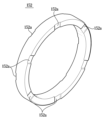
Figure 5 is a perspective view showing a cap according to the present embodiment.
Fig. 6 is a cutaway perspective view showing a first piston according to the present embodiment.
Figure 7 is an enlarged view of part A of Figure 2.
Figure 8 is an enlarged view of part B of Figure 2.
FIG. 9 is an enlarged view of part E of FIG. 8, and is a cross-sectional view of the first sealing member according to the present embodiment.
Fig. 10 is a drawing showing a state in which the first sealing member according to the present embodiment is deformed by the liquid pressure of the pressurized medium.
Fig. 11 is an exploded perspective view showing a second sealing member according to the present embodiment.
Fig. 12 is an enlarged drawing of part F of Fig. 8, and is a cross-sectional view of the second sealing member according to the present embodiment.
Figures 13 and 14 are enlarged views of portion A of Figure 2, showing the forward and returned states of the first piston according to the present embodiment, respectively.
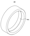
Fig. 15 is a perspective view showing a first bushing member according to the present embodiment.
Fig. 16 is a perspective view showing a damper member according to the present embodiment.
Figure 17 is an enlarged view of section C of Figure 2.
Fig. 18 is a perspective view showing a second bushing member according to the present embodiment.
Fig. 19 is a perspective view showing a third bushing member according to the present embodiment.
Fig. 20 is a cutaway perspective view showing a master cylinder according to the present embodiment.
Fig. 21 is a lateral cross-sectional view of a master cylinder according to the present embodiment, showing a state in which a catch is engaged and supported by a first stopper.
Figure 22 is an enlarged view of portion G of Figure 21.
Fig. 23 is a cross-sectional view in another direction showing the main bore, shaft bore, and communication bore according to the present embodiment.
Fig. 24 is a cross-sectional view in another direction showing a state in which a catch is caught and supported by the first stopper according to the present embodiment.
Figure 25 is an enlarged view of portion D of Figure 2.
Fig. 26 is a side view showing another direction of the second stopper according to the present embodiment.
Fig. 27 is a cross-sectional view taken along the AA' direction of Fig. 25, and is a side view in another direction showing a state in which a second stopper is mounted on the first piston.
이하에서는 본 발명의 실시 예를 첨부 도면을 참조하여 상세히 설명한다. 이하의 실시 예는 본 발명이 속하는 기술분야에서 통상의 지식을 가진 자에게 본 발명의 사상을 충분히 전달하기 위해 제시하는 것이다. 본 발명은 여기서 제시한 실시 예만으로 한정되지 않고 다른 형태로 구체화될 수도 있다. 도면은 본 발명을 명확히 하기 위해 설명과 관계 없는 부분의 도시를 생략하고, 이해를 돕기 위해 구성요소의 크기를 다소 과장하여 표현할 수 있다.Hereinafter, embodiments of the present invention will be described in detail with reference to the accompanying drawings. The following embodiments are presented to sufficiently convey the idea of the present invention to those skilled in the art to which the present invention pertains. The present invention is not limited to the embodiments presented herein and may be embodied in other forms. In order to clarify the present invention, the drawings may omit parts that are not related to the description, and may somewhat exaggerate the sizes of components to help understanding.
도 1은 본 실시 예에 의한 마스터 실린더(1)를 나타내는 사시도이며, 도 2는 본 실시 예에 의한 마스터 실린더(1)를 나타내는 단면도이다. 또한, 도 3은 본 실시 예에 의한 마스터 실린더(1)를 나타내는 절개 사시도이다.Fig. 1 is a perspective view showing a master cylinder (1) according to the present embodiment, and Fig. 2 is a cross-sectional view showing a master cylinder (1) according to the present embodiment. In addition, Fig. 3 is a cut-away perspective view showing a master cylinder (1) according to the present embodiment.
도 1 내지 도 3을 참조하면, 본 실시 예에 의한 마스터 실린더(1)는 내부에 축 방향을 따라 메인보어(111, 112)를 구비하는 유압블록(110), 일측이 메인보어(111, 112)에 삽입되고 타측이 유압블록(110)의 외부로 노출되도록 배치되는 제1 피스톤(121), 메인보어(111, 112) 상에서 제1 피스톤(121) 보다 내측에 삽입되는 제2 피스톤(124), 제1 피스톤(121)과 제2 피스톤(124) 사이에 배치되는 탄성부재(123), 제1 피스톤(121)이 삽입 및 관통되고 유압블록(110)에 결합하는 마운팅블록(140), 유압블록(110)과 마운팅블록(140) 사이에 개재되어 유로를 밀봉하고 가압매체의 누설을 방지하는 제1 실링부재(116) 및 제2 실링부재(117), 제1 피스톤(121)에 마련되는 캡(127), 제1 피스톤(121)과 캡(127)의 간격에 의해 형성되는 간극유로(100)를 포함한다. Referring to FIGS. 1 to 3, a master cylinder (1) according to the present embodiment comprises a hydraulic block (110) having a main bore (111, 112) along the axial direction therein, a first piston (121) arranged so that one side is inserted into the main bore (111, 112) and the other side is exposed to the outside of the hydraulic block (110), a second piston (124) inserted inside the main bore (111, 112) than the first piston (121), an elastic member (123) arranged between the first piston (121) and the second piston (124), a mounting block (140) into which the first piston (121) is inserted and penetrates and which is coupled to the hydraulic block (110), a first sealing member (116) interposed between the hydraulic block (110) and the mounting block (140) to seal the flow path and prevent leakage of the pressurized medium, and a second sealing member (117). It includes a sealing member (117), a cap (127) provided on the first piston (121), and a gap passage (100) formed by the gap between the first piston (121) and the cap (127).
유압블록(110)은 축 방향으로 연장 형성되되 타측(도 2 기준 좌측)이 개방된 메인보어(111, 112)를 구비한다. 메인보어(111, 112)는 후술하는 제1 피스톤(121)의 일측(도 2 기준 우측)이 삽입되어 변위 가능하게 마련되는 제1 보어(111)와, 제1 보어(111)의 내측(도 2 기준 우측)에 형성되고 후술하는 제2 피스톤(124)의 적어도 일부분이 삽입되어 변위 가능하게 마련되는 제2 보어(112)를 포함한다. 즉, 제1 보어(111)와 제2 보어(112)는 축 방향을 기준으로 직렬로 배치되되, 제1 보어(111)가 유압블록(110) 상에서 제2 보어(112) 보다 외측에 배치되고, 제2 보어(112)가 유압블록(110) 상에서 제1 보어(111) 보다 내측에 배치된다. 제2 보어(112)의 직경은 제1 보어(111)의 직경 보다 작게 마련될 수 있으며, 이로 인해 후술하는 바와 같이 제2 보어(112)는 제1 보어(111)에 대향하는 타측 단부(도 2 기준 좌측 단부)에 단차지게 형성되는 제2 단턱부(112a)가 마련된다. The hydraulic block (110) is formed to extend in the axial direction and has a main bore (111, 112) that is open on the other side (left side as shown in FIG. 2). The main bore (111, 112) includes a first bore (111) into which one side (right side as shown in FIG. 2) of a first piston (121) to be described later is inserted and displaced, and a second bore (112) formed on the inner side (right side as shown in FIG. 2) of the first bore (111) and into which at least a portion of a second piston (124) to be described later is inserted and displaced. That is, the first bore (111) and the second bore (112) are arranged in series based on the axial direction, but the first bore (111) is arranged outside the second bore (112) on the hydraulic block (110), and the second bore (112) is arranged inside the first bore (111) on the hydraulic block (110). The diameter of the second bore (112) may be made smaller than the diameter of the first bore (111), and as a result, as described below, the second bore (112) is provided with a second stepped portion (112a) that is formed at the other end (left end based on FIG. 2) opposite to the first bore (111).
유압블록(110)에는 본 실시 예에 의한 마스터 실린더(1)의 메인보어(111, 112) 외에도 가압매체가 이송되는 각종 유로를 포함한다. 일 예로, 유압블록(110)의 타측면에 관통 형성되는 유압유로(119)가 마련될 수 있으며, 유압유로(119)는 가압매체의 누설 등 브레이크 장치의 정상 작동 여부를 검사하는 검사유로 측에 연결될 수 있다. 즉, 유압블록(110)은 차량의 브레이크 시스템을 이루는 밸브블록으로 이해될 수 있다. 유압블록(110)은 지지브래킷(130)에 의해 차체 상에 고정 및 지지될 수 있다. 또한, 유압블록(110)에는 후술하는 바와 같이, 페달의 변위를 감지하는 변위 감지장치(미도시)의 샤프트(20)가 축 방향으로 이동하는 샤프트보어(118)와, 메인보어(111, 112)와 샤프트보어(118)를 연통시켜주는 연통보어(118a)도 마련될 수 있다. 이에 대한 자세한 설명은 도 20 내지 도 24을 참조하여 후술하도록 한다. The hydraulic block (110) includes various paths through which the pressurized medium is transferred in addition to the main bore (111, 112) of the master cylinder (1) according to the present embodiment. For example, a hydraulic oil passage (119) formed penetrating the other side of the hydraulic block (110) may be provided, and the hydraulic oil passage (119) may be connected to a test path side for testing whether the brake device is operating normally, such as for leaks of the pressurized medium. That is, the hydraulic block (110) may be understood as a valve block forming the brake system of the vehicle. The hydraulic block (110) may be fixed and supported on the vehicle body by a support bracket (130). In addition, the hydraulic block (110) may be provided with a shaft bore (118) through which a shaft (20) of a displacement detection device (not shown) that detects the displacement of the pedal moves in the axial direction, as described later, and a communication bore (118a) that connects the main bore (111, 112) and the shaft bore (118). A detailed description thereof will be described later with reference to FIGS. 20 to 24.
제1 보어(111)에는 제1 피스톤(121)의 일측(도 2 기준 우측)이 삽입되어 축 방향을 따라 변위 가능하게 마련될 수 있다. 제1 피스톤(121)의 타측은 유압블록(110)의 외부로 노출되되 후술하는 마운팅블록(140)을 관통하여 인풋로드(11)를 매개로 브레이크 페달(미도시)과 연결될 수 있다. 제1 피스톤(121)은 축 방향을 따라 연장 형성되되 원통 형상으로 마련되는 몸통부(121a)와, 몸통부(121a)의 일측 단부(도 2 기준 우측)에 반경 방향으로 확장 형성되는 걸림부(121b)를 포함한다. 걸림부(121b)는 제1 보어(111)에 수용된 상태로 마련될 수 있으며, 걸림부(121b)의 외경은 후술하는 마운팅블록(140)의 서브보어(142)의 내경 보다 크게 마련될 수 있다. 이를 통해 걸림부(121b)는 제1 피스톤(121)의 복귀(도 2 기준 좌측방향 이동) 시 마운팅블록(140)의 장착돌기(141a)에 의해 걸림으로써 브레이크 페달에 답력이 해제된 상태에서 일정한 위치에 배치될 수 있다. 또한, 제1 피스톤(121)은 일측면(도 2 기준 우측면)에 후술하는 캡(127)와 탄성부재(123)가 안정적으로 결합하도록 축 방향을 따라 함몰 형성되는 장착부(121d)와, 장착부(121d)로부터 연장 형성되는 중공부(121e), 중공부(121e)와 연결포트(149a)를 연통시키도록 반경 방향으로 관통 형성되는 연통홀(121f)과, 장착부(121d)의 내경이 중공부(121e)의 내경 보다 크게 마련됨에 따라 장착부(121d)와 중공부(121e) 사이에 형성되는 단턱면(121g)을 포함한다. 제1 피스톤(121)과 캡(127) 사이의 간격에 의해 간극유로(100)가 형성되며, 이에 대한 자세한 설명은 후술한다. A first piston (121) may be inserted into one side (right side in FIG. 2) of the first bore (111) so as to be displaceable along the axial direction. The other side of the first piston (121) may be exposed to the outside of the hydraulic block (110) and may be connected to a brake pedal (not shown) via an input rod (11) by passing through a mounting block (140) described later. The first piston (121) includes a body part (121a) that is formed to extend along the axial direction and has a cylindrical shape, and a catch part (121b) that is formed to extend radially at one end (right side in FIG. 2) of the body part (121a). The engaging portion (121b) may be provided in a state of being accommodated in the first bore (111), and the outer diameter of the engaging portion (121b) may be provided to be larger than the inner diameter of the sub-bore (142) of the mounting block (140) described later. Through this, the engaging portion (121b) may be arranged at a certain position in a state where the brake pedal is released by being engaged by the mounting projection (141a) of the mounting block (140) when the first piston (121) returns (moves to the left as shown in FIG. 2). In addition, the first piston (121) includes a mounting portion (121d) that is formed recessed along the axial direction so that a cap (127) and an elastic member (123) described later are stably coupled on one side (the right side based on FIG. 2), a hollow portion (121e) that is formed extending from the mounting portion (121d), a communication hole (121f) that is formed radially to communicate the hollow portion (121e) with the connection port (149a), and a stepped surface (121g) that is formed between the mounting portion (121d) and the hollow portion (121e) since the inner diameter of the mounting portion (121d) is formed larger than the inner diameter of the hollow portion (121e). A gap passage (100) is formed by the gap between the first piston (121) and the cap (127), which will be described in detail later.
제2 보어(112)에는 제2 피스톤(124)의 적어도 일부가 삽입되어 축 방향을 따라 변위 가능하게 마련될 수 있다. 제2 피스톤(124)은 제1 피스톤(121)과 후술하는 탄성부재(123)에 의해 변위될 수 있다. 제1 보어(111) 상에서 제1 피스톤(121)과 후술하는 제2 피스톤(124)에 의해 구획되는 공간이 제1 액압챔버(122)를 이룰 수 있으며, 제2 보어(112) 상에서 내측벽과 제2 피스톤(124)에 의해 구획되는 공간이 제2 액압챔버(125)를 이룰 수 있다. 제2 액압챔버(125)에는 제2 피스톤(124)을 탄성 지지하는 리턴 스프링(126)이 마련될 수 있다. 또한, 제1 피스톤(121)과 제2 피스톤(124) 사이에는 압축 및 팽창 가능한 탄성부재(123)가 마련될 수 있으며, 탄성부재(123)의 압축에 의한 탄성 복원력이 운전자에게 페달감으로 제공될 수 있다. 탄성부재(123)의 타측면(도 2 기준 좌측면)에 돌출 형성되어 후술하는 캡(127)에 결합하는 체결돌기(123a)가 마련된다. At least a part of a second piston (124) may be inserted into the second bore (112) and may be provided to be displaceable in the axial direction. The second piston (124) may be displaced by the first piston (121) and an elastic member (123) described later. A space defined by the first piston (121) and the second piston (124) described later on the first bore (111) may form a first hydraulic chamber (122), and a space defined by the inner wall and the second piston (124) on the second bore (112) may form a second hydraulic chamber (125). A return spring (126) for elastically supporting the second piston (124) may be provided on the second hydraulic chamber (125). In addition, a compressible and expandable elastic member (123) may be provided between the first piston (121) and the second piston (124), and elastic restoring force due to compression of the elastic member (123) may be provided as a pedal feel to the driver. A fastening projection (123a) is provided on the other side (left side based on FIG. 2) of the elastic member (123) to be protruded and coupled to a cap (127) described later.
지지브래킷(130)은 차체에 고정 설치되어 유압블록(110) 및 후술하는 마운팅블록(140)을 지지할 수 있다. 지지브래킷(130)은 후술하는 마운팅블록(140)과 결합하는 체결부(131)와, 고정플레이트(133)를 매개로 차체에 고정되는 지지부(132)를 구비할 수 있으며, 복수의 볼트(136)에 의해 체결부(131)와 마운팅블록(140)이 서로 결합하고, 지지부(132)와 차체가 서로 결합 및 고정될 수 있다. 지지브래킷(130)은 충분한 강성을 확보할 수 있도록 스틸 등의 금속 재질로 마련될 수 있다.The support bracket (130) can be fixedly installed on the vehicle body to support the hydraulic block (110) and the mounting block (140) described later. The support bracket (130) can be provided with a fastening portion (131) that is coupled with the mounting block (140) described later, and a support portion (132) that is fixed to the vehicle body via a fixing plate (133). The fastening portion (131) and the mounting block (140) are coupled to each other by a plurality of bolts (136), and the support portion (132) and the vehicle body can be coupled and fixed to each other. The support bracket (130) can be made of a metal material such as steel so as to secure sufficient rigidity.
마운팅블록(140)은 유압블록(110)으로부터 외부로 노출된 제1 피스톤(121)이 삽입되며 유압블록(110)을 고정 및 지지하도록 유압블록(110)과 지지브래킷(130) 사이에 마련될 수 있다. 유압블록(110)은 일측면(도 2 기준 우측면)이 유압블록(110)의 타측면(도 2 기준 좌측면)에 결합하는 설치부(141)와, 타측(도 2 기준 좌측)으로 연장 형성되어 지지브래킷(130)을 관통하는 연장부(143)를 구비할 수 있다. A mounting block (140) may be provided between the hydraulic block (110) and the support bracket (130) to fix and support the hydraulic block (110) by inserting a first piston (121) exposed externally from the hydraulic block (110). The hydraulic block (110) may have an installation part (141) that is coupled to the other side (the left side as shown in FIG. 2) of the hydraulic block (110) on one side (the right side as shown in FIG. 2) and an extension part (143) that is formed to extend to the other side (the left side as shown in FIG. 2) and penetrate the support bracket (130).
또한 마운팅블록(140)은 축 방향으로 관통 및 연장 형성되는 서브보어(142)를 구비한다. 서브보어(142)는 제1 피스톤(121)이 삽입 및 관통되어 변위 가능하게 마련될 수 있다. 서브보어(142)의 일측 단부(도 2 기준 우측 단부)에는 단차지게 형성되는 제1 단턱부(142a)가 마련될 수 있으며, 설치부(141)의 일측면(도 2 기준 우측면) 상 서브보어(142)의 일측 단부의 둘레에는 축 방향을 따라 돌출 형성되는 장착돌기(141a)가 마련될 수 있다. 장착돌기(141a)는 유압블록(110)의 제1 보어(111)에 삽입되어 장착돌기(141a)의 외주면이 제1 보어(111)의 내주면에 대향 또는 접촉함으로써 유압블록(110)과 마운팅블록(140) 간 용이한 장착 및 결합을 도모할 수 있다. In addition, the mounting block (140) has a sub-bore (142) that is formed to penetrate and extend in the axial direction. The sub-bore (142) can be provided so that the first piston (121) can be inserted and penetrated and displaced. A first step portion (142a) formed in a step may be provided on one end portion (the right end based on FIG. 2) of the sub-bore (142), and a mounting projection (141a) formed to protrude along the axial direction may be provided on the periphery of one end portion of the sub-bore (142) on one side surface (the right side based on FIG. 2) of the installation portion (141). The mounting projection (141a) is inserted into the first bore (111) of the hydraulic block (110), and the outer surface of the mounting projection (141a) faces or contacts the inner surface of the first bore (111), thereby facilitating easy mounting and coupling between the hydraulic block (110) and the mounting block (140).
연장부(143)의 타측 단부에는 먼지 등의 이물질이 서브보어(142) 및 유압블록(110)의 내부로 유입되는 것을 방지하는 부트(146)가 마련될 수 있다. 부트(146)는 일단이 마운팅블록(140)의 연장부(143)에 지지되고, 타단이 인풋로드(11)에 고정 설치되는 지지플레이트(147)에 지지될 수 있으며, 인풋로드(11)의 변위에 따라 신축 및 확장될 수 있다. 또한 연장부(143)의 타측 단부에는 인풋로드(11)를 탄성적으로 지지하여 제1 피스톤(121)의 복귀를 발생시키는 피스톤 스프링(148)이 지지될 수 있다. 피스톤 스프링(148)은 부트(146)의 내측에 배치될 수 있으며, 부트(146)와 피스톤 스프링(148) 사이에는 피스톤 스프링(148)의 동작에 의해 소음과 진동을 저감하는 소음억제돌기(144)가 마련될 수 있다. 이에 대한 자세한 설명은 도 25을 참조하여 후술하도록 한다. A boot (146) may be provided at the other end of the extension (143) to prevent foreign substances such as dust from entering the sub-bore (142) and the inside of the hydraulic block (110). The boot (146) may have one end supported by the extension (143) of the mounting block (140) and the other end supported by a support plate (147) fixedly installed to the input rod (11), and may be stretched and expanded according to the displacement of the input rod (11). In addition, a piston spring (148) may be supported at the other end of the extension (143) to elastically support the input rod (11) and cause the return of the first piston (121). The piston spring (148) may be placed on the inside of the boot (146), and a noise-suppressing projection (144) may be provided between the boot (146) and the piston spring (148) to reduce noise and vibration due to the operation of the piston spring (148). A detailed description thereof will be described later with reference to FIG. 25.
서브보어(142)에는 가압매체가 수용되는 리저버와 유압적으로 연통되는 연결포트(149a)가 마련될 수 있다. 연결포트(149a)의 일측 및 타측에는 연결포트(149a)를 통과하는 가압매체의 누설을 방지하는 적어도 하나의 시일(149b)이 마련될 수 있다. 시일(149b)은 서브보어(142)의 내주면 상에 함몰 형성되는 시일홈에 안착 및 수용될 수 있다. 연결포트(129a)는 후술하는 간극유로(100)에 의해 제1 액압챔버(122)와 연통될 수 있으며, 이에 대한 자세한 설명은 도 4 내지 도 7을 참조하여 후술한다. A connecting port (149a) that is hydraulically connected to a reservoir that receives a pressurized medium may be provided in the sub-bore (142). At least one seal (149b) that prevents leakage of the pressurized medium passing through the connecting port (149a) may be provided on one side and the other side of the connecting port (149a). The seal (149b) may be seated and received in a seal groove that is formed by being sunken on the inner surface of the sub-bore (142). The connecting port (129a) may be connected to the first hydraulic chamber (122) by a gap passage (100) described later, and a detailed description thereof will be described later with reference to FIGS. 4 to 7.
마운팅블록(140)은 서브보어(142)와 유압블록(110)의 유압유로(119)를 연통시키는 연결유로(145)를 포함할 수 있다. 유압블록(110)의 유압유로(119)는 메인보어(111, 112)로부터 일정 거리 이격되어 마련될 수 있으며, 이에 따라 연결유로(145)는 일단이 마운팅블록(140)의 설치부(141) 일측면 상에 노출되고 타단이 포트(149a) 등을 매개로 서브보어(142)에 연결되되, 축 방향에 대해 일정 각도 경사지게 관통 형성될 수 있다. 본 실시 예에 의한 마스터 실린더(1)는 용이한 설치 및 조립를 위해 유압블록(110)과 마운팅블록(140)이 개별적으로 제조된 후, 유압블록(110)의 타측면과 마운팅블록(140)의 일측면이 상호 면 결합하여 마련되며, 이로 인해 유압블록(110)의 유로와 마운팅블록(140)의 보어가 서로 연통될 필요가 발생하므로 마운팅블록(140)에 연결유로(145)를 축 방향에 대해 소정 각도 경사지게 관통 형성함으로써 가압매체의 흐름을 원활하게 유지할 수 있다.The mounting block (140) may include a connecting passage (145) that connects the sub-bore (142) and the hydraulic oil passage (119) of the hydraulic block (110). The hydraulic oil passage (119) of the hydraulic block (110) may be provided at a certain distance from the main bore (111, 112), and accordingly, the connecting passage (145) may have one end exposed on one side of the installation portion (141) of the mounting block (140) and the other end connected to the sub-bore (142) via a port (149a), etc., and may be formed to penetrate at a certain angle with respect to the axial direction. In the master cylinder (1) according to the present embodiment, the hydraulic block (110) and the mounting block (140) are manufactured separately for easy installation and assembly, and then the other side of the hydraulic block (110) and the one side of the mounting block (140) are mutually surface-coupled. As a result, the flow path of the hydraulic block (110) and the bore of the mounting block (140) need to be connected to each other, so that a connecting flow path (145) is formed through the mounting block (140) at a predetermined angle with respect to the axial direction, thereby maintaining a smooth flow of the pressurized medium.
제1 피스톤(121)과 탄성부재(123) 사이에는 제1 액압챔버(122)에 존재하는 가압매체의 잔압을 제거하도록 간극유로(100)(100)를 형성하는 캡(127)이 마련된다. Between the first piston (121) and the elastic member (123), a cap (127) is provided to form a gap passage (100)(100) to remove residual pressure of the pressurized medium existing in the first hydraulic chamber (122).
도 4는 제1 피스톤(121)에 캡(127)이 마련된 상태를 나타내는 절개 사시도이다. 또한 도 5는 캡(127)을 나타내는 사시도이며, 도 6은 제1 피스톤(121)을 나타내는 절개 사시도이다. 도 7은 도 2의 A 부분을 확대 도시한 도면이다.Fig. 4 is a cutaway perspective view showing a state where a cap (127) is provided on the first piston (121). Also, Fig. 5 is a perspective view showing the cap (127), and Fig. 6 is a cutaway perspective view showing the first piston (121). Fig. 7 is an enlarged view of part A of Fig. 2.
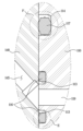
도 4 내지 도 7을 참조하면, 캡(127)은 제1 피스톤(121)의 일측부(도 2 및 도 7 기준 우측부)와 탄성부재(123)의 타측부(도 2 및 도 7 기준 좌측부) 사이에 개재될 수 있다. 캡(127)은 장착부(121d)에 삽입되는 메인바디(127a)와, 메인바디(127a)의 일측 단부(도 7 기준 우측 단부)에 반경 방향으로 확장 형성되는 플랜지부(127b)와, 탄성부재(123)의 체결돌기(123a)가 삽입되어 장착되는 체결홀(127c)을 포함한다. Referring to FIGS. 4 to 7, a cap (127) can be interposed between one side (the right side based on FIGS. 2 and 7) of a first piston (121) and the other side (the left side based on FIGS. 2 and 7) of an elastic member (123). The cap (127) includes a main body (127a) inserted into a mounting portion (121d), a flange portion (127b) formed to extend radially at one end (the right end based on FIG. 7) of the main body (127a), and a fastening hole (127c) into which a fastening projection (123a) of an elastic member (123) is inserted and mounted.
캡(127)과 제1 피스톤(121)의 안정적인 결합을 위해 메인바디(127a)의 외주면과 장착부(121d)의 내주면이 서로 대향 또는 접촉할 수 있으며, 메인바디(127a)의 내측은 탄성부재(123)가 용이하게 진입할 수 있도록 중공 형성될 수 있다. 메인바디(127a)는 장착부(121d)에 압입 결합될 수 있으나, 이에 한정되는 것은 아니며 다양한 방식으로 결합될 수 있음은 물론이다. In order to stably combine the cap (127) and the first piston (121), the outer surface of the main body (127a) and the inner surface of the mounting portion (121d) may face or contact each other, and the inner side of the main body (127a) may be formed hollow so that the elastic member (123) can easily enter. The main body (127a) may be press-fitted to the mounting portion (121d), but is not limited thereto, and it is obvious that the main body (127a) may be combined in various ways.
간극유로(100)는 메인바디(127a)의 외주면에 축 방향을 따라 함몰 형성되는 제1 슬릿(101)과, 제1 피스톤(121)의 일측 단부(도 2 및 도 7 기준 우측 단부)와 대향하는 플랜지부(127b)의 타측면에 반경 방향을 따라 함몰 형성되고 제1 슬릿(101)과 연결되는 제2 슬릿(102)과, 제1 피스톤(121)의 단턱면(121g)에 반경 방향을 따라 함몰 형성되어 제2 슬릿(102)과 연결되는 제3 슬릿(103)과, 제1 피스톤(121)의 단턱면(121g)에 둘레 방향을 따라 함몰 형성되어 인접한 제3 슬릿(103)을 서로 연결하는 제4 슬릿(104)을 포함한다. The gap passage (100) includes a first slit (101) that is formed axially on the outer surface of the main body (127a), a second slit (102) that is formed radially on the other side of the flange portion (127b) facing one end (the right end based on FIGS. 2 and 7) of the first piston (121) and is connected to the first slit (101), a third slit (103) that is formed radially on the step surface (121g) of the first piston (121) and is connected to the second slit (102), and a fourth slit (104) that is formed radially on the step surface (121g) of the first piston (121) and is connected to the adjacent third slits (103).
제2 슬릿(102)이 플랜지부(127b) 상에 형성됨에 따라 제2 슬릿(102)은 제1 액압챔버(122)와 유압적으로 연통될 수 있다. 또한, 제2 슬릿(102)이 제1 슬릿(101)과, 제3 슬릿(103) 및 제4 슬릿(104)과 서로 연결되는 바, 제1 액압챔버(122)가 중공부(121d)와, 연통홀(121f)을 매개로 연결포트(149a)와 유압적으로 연통될 수 있다. 연결포트(149a)는 리저버(미도시)와 연결됨에 따라, 간극유로(100)를 통해 제1 액압챔버(122)와 리저버가 유압적으로 연통될 수 있다. As the second slit (102) is formed on the flange portion (127b), the second slit (102) can be hydraulically connected to the first hydraulic chamber (122). In addition, as the second slit (102) is connected to the first slit (101), the third slit (103), and the fourth slit (104), the first hydraulic chamber (122) can be hydraulically connected to the hollow portion (121d) and the connection port (149a) through the communication hole (121f). As the connection port (149a) is connected to the reservoir (not shown), the first hydraulic chamber (122) and the reservoir can be hydraulically connected through the gap passage (100).
캡(127)과 간극유로(100)를 통한 가압매체의 잔압 제거에 대해 설명하면, 브레이크 시스템의 정상 작동모드에서 고장 등에 의해 폴백(Fallback)모드로 급격히 전환 시, 브레이크 시스템의 모터 또는 펌프(미도시) 등에서 제공되는 가압매체의 액압이 순간적으로 제1 액압챔버(122)로 전달될 수 있는데, 이로 인해 제1 액압챔버(122) 내부의 액압이 해제되지 않고 잔압이 남을 수 있다. 이 경우 운전자가 차량의 제동을 섬세하게 제어하는 것이 어려울 수 있으며, 브레이크 페달의 답력에도 영향을 주어 운전자가 이질감을 느낄 수 있다. Regarding the removal of residual pressure of the pressurized medium through the cap (127) and the gap passage (100), when the normal operation mode of the brake system is suddenly switched to the fallback mode due to a failure, etc., the hydraulic pressure of the pressurized medium provided from the motor or pump (not shown) of the brake system may be instantaneously transferred to the first hydraulic chamber (122), which may cause the hydraulic pressure inside the first hydraulic chamber (122) not to be released and the residual pressure to remain. In this case, it may be difficult for the driver to delicately control the braking of the vehicle, and the brake pedal pressure may also be affected, causing the driver to feel a sense of incongruity.
이에 제1 액압챔버(122)에 가압매체의 잔압이 남아 있는 경우, 제1 피스톤(121)과 캡(127)의 간격에 의해 형성되는 간극유로(100)가 가압매체의 잔압을 리저버로 배출할 수 있다. 구체적으로, 제1 액압챔버(122)의 잔압은 캡(127)의 제2 슬릿(102), 제1 슬릿(101), 제3 슬릿(103)을 순차적으로 경유하여 제1 피스톤(121) 내측의 중공부(121d)로 전달될 수 있으며, 중공부(121d)로 유입된 가압매체는 연통홀(121f)과 연결포트(149a)를 거쳐 리저버로 배출될 수 있다. 이를 통해 드래그 현상 등을 방지할 수 있음은 물론이며, 제1 피스톤의 스트로크를 일정하게 유지할 수 있다. Accordingly, when the residual pressure of the pressurized medium remains in the first hydraulic chamber (122), the gap passage (100) formed by the gap between the first piston (121) and the cap (127) can discharge the residual pressure of the pressurized medium to the reservoir. Specifically, the residual pressure of the first hydraulic chamber (122) can be sequentially transmitted to the hollow portion (121d) inside the first piston (121) through the second slit (102), the first slit (101), and the third slit (103) of the cap (127), and the pressurized medium introduced into the hollow portion (121d) can be discharged to the reservoir through the communication hole (121f) and the connection port (149a). Through this, it is possible to prevent the drag phenomenon, etc., and to maintain the stroke of the first piston constant.
유압블록(110)과 마운팅블록(140) 사이에는 가압매체의 누설을 방지하도록 제1 및 제2 실링부재(116, 117)가 개재될 수 있다. First and second sealing members (116, 117) may be interposed between the hydraulic block (110) and the mounting block (140) to prevent leakage of the pressurized medium.
도 8는 도 2의 B 부분을 확대 도시한 도면이고, 도 9는 도 8의 E 부분을 확대 도시한 도면으로서, 도 2 내지 도 10를 참조하면 제1 실링부재(116)는 마운팅블록(140)의 일측면(도 2 기준 우측면)과 유압블록(110)의 타측면(도 2 기준 좌측면) 사이에 개재될 수 있으며, 유압블록(110)의 유압유로(119)와 마운팅블록(140)의 연결유로(145)를 밀봉시키도록 마련된다. 제1 실링부재(116)는 마운팅블록(140)의 일측면 상 연결유로(145)의 개구 또는 유압블록(110)의 타측면 상 유압유로(119)의 개구 주변을 따라 연장 형성되어 링 형상으로 마련될 수 있다. 또한, 제1 실링부재(116)는 유압블록(110)의 타측면 상 유압유로(119)의 개구 주변을 따라 함몰 형성되는 제1 수용홈(113)에 삽입 및 안착됨으로써 고압의 가압매체가 유압유로(119) 또는 연결유로(145)로부터 전달되는 경우에도 제1 실링부재(116)의 이탈을 방지할 수 있다. FIG. 8 is an enlarged view of portion B of FIG. 2, and FIG. 9 is an enlarged view of portion E of FIG. 8. Referring to FIGS. 2 to 10, the first sealing member (116) may be interposed between one side (the right side as shown in FIG. 2) of the mounting block (140) and the other side (the left side as shown in FIG. 2) of the hydraulic block (110), and is provided to seal the hydraulic oil passage (119) of the hydraulic block (110) and the connecting oil passage (145) of the mounting block (140). The first sealing member (116) may be provided in a ring shape by extending along the periphery of the opening of the connecting oil passage (145) on one side of the mounting block (140) or the opening of the hydraulic oil passage (119) on the other side of the hydraulic block (110). In addition, the first sealing member (116) is inserted and seated in the first receiving groove (113) formed along the periphery of the opening of the hydraulic oil passage (119) on the other side of the hydraulic block (110), thereby preventing the first sealing member (116) from being detached even when a high-pressure pressurized medium is transmitted from the hydraulic oil passage (119) or the connecting passage (145).
제1 실링부재(116)는 유압유로(119) 또는 연결유로(145)로부터 고압의 가압매체가 전달되는 경우에도 효과적으로 누설을 방지할 수 있도록 중앙의 제1 몸체부(116a)와, 제1 몸체부(116a)의 양측에 제1 날개부(116b) 및 제2 날개부(116c)가 각각 마련될 수 있다. The first sealing member (116) can effectively prevent leakage even when a high-pressure medium is transmitted from a hydraulic oil path (119) or a connecting oil path (145). A first body part (116a) in the center and first wing parts (116b) and second wing parts (116c) can be provided on both sides of the first body part (116a).
도 10은 가압매체의 액압에 의해 제1 실링부재(116)가 변형된 상태를 나타내는 도면으로서, 도 9 및 도 10을 참조하면, 제1 실링부재(116)는 중앙에 마련되어 주요 몸체를 이루는 제1 몸체부(116a)와, 제1 몸체부(116a) 상에 유압유로(119)에 인접하는 내측(도 9 및 도 10 기준 상측)으로 돌출 형성되는 제1 날개부(116b)와, 제1 몸체부(116a) 상에서 유압유로(119)로부터 이격되는 외측(도 9 및 도 10 기준 하측)으로 돌출 형성되는 제2 날개부(116c)를 포함할 수 있다. 제1 날개부(116b)의 내주면 및 제2 날개부(116c)의 외주면, 다시 말해 제1 수용홈(113)의 내면에 대향하는 부위는 고압의 가압매체가 전달되는 경우에도 가압매체의 누설을 안정적으로 방지할 수 있도록 제1 수용홈(113)의 내면과 서로 면 접촉될 수 있다. 이를 위해, 제1 날개부(116b)의 내주면과 제2 날개부(116c)의 외주면은 각각 제1 수용홈(113)의 내면 형상에 상응하게 마련될 수 있다. 이를 통해 도 10에 도시된 바와 같이 유압유로(119) 또는 연결유로(145)로부터 가압매체가 전달되더라도 제2 날개부(116c)의 외주면과 제1 수용홈(113)의 내면의 접촉 면적이 확대되어 가압매체의 누설을 보다 효과적으로 억제 및 방지할 수 있다. FIG. 10 is a drawing showing a state in which the first sealing member (116) is deformed by the liquid pressure of the pressurized medium. Referring to FIGS. 9 and 10, the first sealing member (116) may include a first body portion (116a) provided in the center and forming a main body, a first wing portion (116b) formed to protrude inwardly (upper with reference to FIGS. 9 and 10) adjacent to a hydraulic oil passage (119) on the first body portion (116a), and a second wing portion (116c) formed to protrude outwardly (lower with reference to FIGS. 9 and 10) away from the hydraulic oil passage (119) on the first body portion (116a). The inner surface of the first wing part (116b) and the outer surface of the second wing part (116c), in other words, the portions facing the inner surface of the first receiving groove (113), can be in surface contact with the inner surface of the first receiving groove (113) so as to stably prevent leakage of the pressurized medium even when a high-pressure pressurized medium is transmitted. To this end, the inner surface of the first wing part (116b) and the outer surface of the second wing part (116c) can be provided so as to correspond to the inner shape of the first receiving groove (113), respectively. As a result, as illustrated in FIG. 10, even when the pressurized medium is transmitted from the hydraulic oil path (119) or the connecting oil path (145), the contact area between the outer surface of the second wing part (116c) and the inner surface of the first receiving groove (113) is expanded, so that leakage of the pressurized medium can be more effectively suppressed and prevented.
또한, 가압매체의 전달 시 제1 날개부(116b) 및 제2 날개부(116c)의 용이한 변형을 위해 제1 날개부(116b) 또는 제2 날개부(116c)의 두께(도 9 기준 좌우 방향 폭)는 제1 몸체부(116a)의 두께보다 작게 마련될 수 있다. 구체적으로, 제1 몸체부(116a)는 제1 수용홈(113) 상에서 양측이 유압블록(110) 및 마운팅블록(140)에 접촉한 상태를 유지하도록 단면 형상이 중앙을 향할수록 두꺼워지는 원형의 형상으로 마련될 수 있으며, 제1 날개부(116b)의 두께 또는 제2 날개부(116c)의 두께는 제1 몸체부(116a)의 직경보다 작게 마련될 수 있다. 이를 통해 유압유로(119) 또는 연결유로(145)로부터 가압매체가 전달되더라도 1차적으로 제1 몸체부(116a)가 유압블록(110)과 마운팅블록(140) 사이를 밀봉하고, 2차적으로 제1 날개부(116b) 또는 제2 날개부(116c)가 용이하게 변형되어 제1 수용홈(113)과의 접촉 면적을 신속하게 확대시킴으로써 가압매체의 누설 방지를 안정적으로 구현할 수 있다. In addition, in order to easily deform the first wing part (116b) and the second wing part (116c) when transmitting the pressurized medium, the thickness (left-right width based on FIG. 9) of the first wing part (116b) or the second wing part (116c) may be provided to be smaller than the thickness of the first body part (116a). Specifically, the first body part (116a) may be provided to have a circular shape whose cross-sectional shape becomes thicker toward the center so that both sides on the first receiving groove (113) maintain contact with the hydraulic block (110) and the mounting block (140), and the thickness of the first wing part (116b) or the thickness of the second wing part (116c) may be provided to be smaller than the diameter of the first body part (116a). Through this, even if the pressurized medium is transmitted from the hydraulic oil path (119) or the connecting oil path (145), the first body part (116a) primarily seals between the hydraulic block (110) and the mounting block (140), and secondly, the first wing part (116b) or the second wing part (116c) is easily deformed to quickly expand the contact area with the first receiving groove (113), thereby stably preventing the pressurized medium from leaking.
도 11은 본 실시 예에 의한 제2 실링부재(117)를 나타내는 분해 사시도이며, 도 12은 도 8의 F 부분을 확대 도시한 도면으로서, 도 2, 도 11 및 도 12을 참조하면, 제2 실링부재(117)는 마운팅블록(140)의 일측면(도 2 기준 우측면)과 유압블록(110)의 타측면(도 2 기준 좌측면) 사이에 개재될 수 있으며, 유압블록(110)의 메인보어(111, 112)와 샤프트보어(118)를 밀봉시키도록 마련된다. FIG. 11 is an exploded perspective view showing a second sealing member (117) according to the present embodiment, and FIG. 12 is an enlarged view of part F of FIG. 8. Referring to FIGS. 2, 11, and 12, the second sealing member (117) can be interposed between one side of the mounting block (140) (the right side as shown in FIG. 2) and the other side of the hydraulic block (110) (the left side as shown in FIG. 2), and is provided to seal the main bore (111, 112) and shaft bore (118) of the hydraulic block (110).
샤프트보어(118)는 유압블록(110) 상에서 메인보어(111, 112)에 대해 일정 거리 이격되어 배치될 수 있으며, 축 방향을 따라 연장 형성되어 브레이크 페달의 변위 감지장치의 샤프트(20)(미도시)가 변위 가능하게 배치될 수 있다. 메인보어(111, 112)와 샤프트보어(118) 사이에는 제1 피스톤(121)과 샤프트(20)를 연결하는 연결부재가 수용되는 연통보어(118a)가 축 방향을 따라 연장 형성될 수 있다(도 20 및 19 참조). The shaft bore (118) may be arranged at a predetermined distance from the main bore (111, 112) on the hydraulic block (110), and may be formed to extend along the axial direction so that the shaft (20) (not shown) of the displacement detection device of the brake pedal may be arranged to be displaceable. Between the main bore (111, 112) and the shaft bore (118), a communication bore (118a) may be formed to extend along the axial direction to accommodate a connecting member connecting the first piston (121) and the shaft (20) (see FIGS. 20 and 19).
제2 실링부재(117)는 유압블록(110)의 타측면 상 메인보어(111, 112)의 개구와 샤프트보어(118)의 개구 주변을 따라 연장 형성될 수 있다. 또한, 제2 실링부재(117)는 유압블록(110)의 타측면 상 메인보어(111, 112)의 개구와 샤프트보어(118)의 개구 주변을 따라 함몰 형성되는 제2 수용홈(114)에 삽입 및 안착될 수 있으며, 이를 통해 고압의 가압매체가 메인보어(111, 112) 또는 샤프트보어(118)로부터 전달되는 경우에도 제2 실링부재(117)의 이탈을 방지할 수 있다. The second sealing member (117) may be formed to extend along the periphery of the opening of the main bore (111, 112) and the opening of the shaft bore (118) on the other side of the hydraulic block (110). In addition, the second sealing member (117) may be inserted and seated in the second receiving groove (114) formed to be sunken along the periphery of the opening of the main bore (111, 112) and the opening of the shaft bore (118) on the other side of the hydraulic block (110), thereby preventing the second sealing member (117) from being detached even when a high-pressure pressurized medium is transmitted from the main bore (111, 112) or the shaft bore (118).
제2 실링부재(117)는 유압유로(119) 또는 연결유로(145)로부터 고압의 가압매체가 전달되는 경우에도 효과적으로 누설을 방지할 수 있도록 중앙의 제2 몸체부(117a)와, 제2 몸체부(117a)의 양측에 제3 날개부(117b) 및 제4 날개부(117c)가 각각 마련될 수 있다. The second sealing member (117) can effectively prevent leakage even when a high-pressure medium is transmitted from the hydraulic oil path (119) or the connecting oil path (145). A second body part (117a) in the center and third wing parts (117b) and fourth wing parts (117c) can be provided on both sides of the second body part (117a).
제2 실링부재(117)는 중앙에 마련되어 주요 몸체를 이루는 제2 몸체부(117a)와, 제2 몸체부(117a) 상에 메인보어(111, 112) 또는 샤프트보어(118)에 내측(도 12 기준 상측)으로 돌출 형성되는 제3 날개부(117b)와, 제2 몸체부(117a) 상에서 메인보어(111, 112) 또는 샤프트보어(118)로부터 이격되는 외측(도 12 기준 하측)으로 돌출 형성되는 제4 날개부(117c)를 포함할 수 있다. 제3 날개부(117b)의 내주면 및 제4 날개부(117c)의 외주면, 다시 말해 제2 수용홈(114)의 내면에 대향하는 부위는 고압의 가압매체가 전달되는 경우에도 가압매체의 누설을 안정적으로 방지할 수 있도록 제2 수용홈(114)의 내면과 서로 면 접촉될 수 있다. 이를 위해, 제3 날개부(117b)의 내주면과 제4 날개부(117c)의 외주면은 각각 제2 수용홈(114)의 내면 형상에 상응하게 마련될 수 있다. 이를 통해 도 10에 도시된 제1 실링부재(116)와 마찬가지로, 메인보어(111, 112) 또는 샤프트보어(118)로부터 가압매체가 전달되더라도 제4 날개부(117c)의 외주면과 제2 수용홈(114)의 내면의 접촉 면적이 확대되어 가압매체의 누설을 보다 효과적으로 억제 및 방지할 수 있다. The second sealing member (117) may include a second body portion (117a) provided in the center and forming the main body, a third wing portion (117b) formed to protrude inwardly (upper as shown in FIG. 12) from the main bore (111, 112) or shaft bore (118) on the second body portion (117a), and a fourth wing portion (117c) formed to protrude outwardly (lower as shown in FIG. 12) from the main bore (111, 112) or shaft bore (118) on the second body portion (117a). The inner surface of the third wing part (117b) and the outer surface of the fourth wing part (117c), in other words, the portions facing the inner surface of the second receiving groove (114), can be in surface contact with the inner surface of the second receiving groove (114) so as to stably prevent leakage of the pressurized medium even when a high-pressure pressurized medium is transmitted. To this end, the inner surface of the third wing part (117b) and the outer surface of the fourth wing part (117c) can be respectively provided to correspond to the inner shape of the second receiving groove (114). Through this, similar to the first sealing member (116) illustrated in FIG. 10, even when the pressurized medium is transmitted from the main bore (111, 112) or the shaft bore (118), the contact area between the outer surface of the fourth wing part (117c) and the inner surface of the second receiving groove (114) is expanded, so that leakage of the pressurized medium can be more effectively suppressed and prevented.
또한, 가압매체의 전달 시 제3 날개부(117b) 및 제4 날개부(117c)의 용이한 변형을 위해 제3 날개부(117b) 또는 제4 날개부(117c)의 두께(도 12 기준 좌우 방향 폭)는 제2 몸체부(117a)의 두께보다 작게 마련될 수 있다. 구체적으로, 제2 몸체부(117a)는 제2 수용홈(114) 상에서 양측이 유압블록(110) 및 마운팅블록(140)에 접촉한 상태를 유지하도록 단면 형상이 중앙을 향할수록 두꺼워지는 원형의 형상으로 마련될 수 있으며, 제3 날개부(117b)의 두께 또는 제4 날개부(117c)의 두께는 제2 몸체부(117a)의 직경보다 작게 마련될 수 있다. 이를 통해 메인보어(111, 112) 또는 샤프트보어(118)로부터 가압매체가 전달되더라도 1차적으로 제2 몸체부(117a)가 유압블록(110)과 마운팅블록(140) 사이를 밀봉하고, 2차적으로 제3 날개부(117b) 또는 제4 날개부(117c)가 용이하게 변형되어 제2 수용홈(114)과의 접촉 면적을 신속하게 확대시킴으로써 가압매체의 누설 방지를 안정적으로 구현할 수 있다. In addition, in order to easily deform the third wing part (117b) and the fourth wing part (117c) when transmitting the pressurized medium, the thickness (left-right width based on FIG. 12) of the third wing part (117b) or the fourth wing part (117c) may be provided to be smaller than the thickness of the second body part (117a). Specifically, the second body part (117a) may be provided to have a circular shape whose cross-sectional shape becomes thicker toward the center so that both sides on the second receiving groove (114) maintain contact with the hydraulic block (110) and the mounting block (140), and the thickness of the third wing part (117b) or the thickness of the fourth wing part (117c) may be provided to be smaller than the diameter of the second body part (117a). Through this, even if the pressurized medium is delivered from the main bore (111, 112) or shaft bore (118), the second body part (117a) primarily seals between the hydraulic block (110) and the mounting block (140), and secondarily, the third wing part (117b) or the fourth wing part (117c) is easily deformed to quickly expand the contact area with the second receiving groove (114), thereby stably preventing leakage of the pressurized medium.
부쉬부재는 제1 피스톤(121)과 제2 피스톤(124)의 원활한 왕복 이동을 가이드함과 동시에, 피스톤과 보어 간 과도한 마찰 및 긁힘을 방지하도록 마련된다.The bushing member is provided to guide smooth reciprocating movement of the first piston (121) and the second piston (124) while preventing excessive friction and scratching between the piston and the bore.
도 13 및 도 14은 도 2의 A 부분을 확대 도시한 도면이며, 도 15은 제1 부쉬부재(151)를 나타내는 사시도이고, 도 16는 댐퍼부재(152)를 나타내는 사시도이다.FIG. 13 and FIG. 14 are enlarged views of part A of FIG. 2, FIG. 15 is a perspective view showing the first bushing member (151), and FIG. 16 is a perspective view showing the damper member (152).
도 2, 도 3, 도 13 내지 도 16를 참조하면, 제1 부쉬부재(151)는 제1 피스톤(121)의 일측(도 2, 도 13 및 도 14 기준 우측)에 인접하게 마련되어, 제1 피스톤(121)의 안정적인 습동을 도모하도록 전진 및 복귀 운동을 가이드함과 동시에, 마운팅블록(140)과의 접촉에 의한 마모와 파손을 방지하도록 마련된다. 서브보어(142)의 일측 단부(도 13 및 도 14 기준 우측 단부)에는 단차지게 형성되어 서브보어(142)의 내경 보다 큰 내경을 갖는 제1 단턱부(142a)가 마련되는 바, 제1 부쉬부재(151)는 링 형상으로 마련되되 외주면이 제1 단턱부(142a)의 내주면에 접하도록 마련될 수 있다. 제1 단턱부(142a) 상에서 제1 부쉬부재(151)의 안정적인 지지와 이탈을 방지하도록 제1 부쉬부재(151)의 외주면은 제1 단턱부(142a)의 내주면에 압입 결합될 수 있다. 제1 부쉬부재(151)는 플라스틱 소재로 마련될 수 있으며, 제1 부쉬부재(151)의 내주면 직경은 제1 피스톤(121)의 몸통부(121a) 외주면 직경에 상응하게 마련될 수 있다.Referring to FIGS. 2, 3, 13 to 16, the first bushing member (151) is provided adjacent to one side (the right side with respect to FIGS. 2, 13 and 14) of the first piston (121) to guide the forward and return movements to ensure stable sliding of the first piston (121) and to prevent wear and damage due to contact with the mounting block (140). A first stepped portion (142a) is provided at one end (the right side with respect to FIGS. 13 and 14) of the sub-bore (142) to have a stepped shape and an inner diameter larger than the inner diameter of the sub-bore (142). The first bushing member (151) may be provided in a ring shape, but may be provided such that the outer circumference is in contact with the inner circumference of the first stepped portion (142a). In order to stably support the first bushing member (151) and prevent it from coming off on the first step portion (142a), the outer surface of the first bushing member (151) may be press-fitted to the inner surface of the first step portion (142a). The first bushing member (151) may be made of a plastic material, and the inner surface diameter of the first bushing member (151) may be provided to correspond to the outer surface diameter of the body portion (121a) of the first piston (121).
댐퍼부재(152)는 제1 피스톤(121)의 복귀(도 2, 도 13 및 도 14 기준 좌측 방향 이동) 시, 제1 피스톤(121)과 마운팅블록(140) 간 충격에 의한 소음과 진동을 방지하도록 마련된다. 댐퍼부재(152)는 제1 피스톤(121)의 외주면 상 일측 단부(도 13 및 도 14 기준 우측 단부)에 인접하게 배치될 수 있으며, 제1 피스톤(121)과 마운팅블록(140) 간 접촉에 의한 충격을 완화하기 위해 탄성 변형 가능한 재질로 마련될 수 있다. 제1 피스톤(121) 상에서 댐퍼부재(152)가 안정적으로 지지됨과 동시에 이탈을 방지하도록 제1 피스톤(121)의 외주면에 원주 방향을 따라 함몰 형성되는 댐퍼홈에 인입 및 밀착될 수 있다. 또한, 댐퍼부재(152)는 일측(도 13 및 도 14 기준 우측)이 제1 피스톤(121)의 걸림부(121b)에 지지되고, 타측(도 13 및 도 14 기준 좌측)이 제1 부쉬부재(151)에 대향 및 접촉 가능하게 마련될 수 있으며, 댐퍼부재(152)는 제1 피스톤(121)의 왕복 이동에 따라 제1 단턱부(142a)의 내측에 진입될 수 있다. 댐퍼부재(152)는 압축 및 복원이 용이하고 신속하게 이루어질 수 있도록 일측면과 타측면 중 적어도 어느 하나에 함몰 형성되는 외측홈부(152a)가 마련될 수 있다. The damper member (152) is provided to prevent noise and vibration caused by impact between the first piston (121) and the mounting block (140) when the first piston (121) returns (moves to the left with reference to FIGS. 2, 13, and 14). The damper member (152) may be arranged adjacent to one end (the right end with reference to FIGS. 13 and 14) on the outer surface of the first piston (121) and may be provided with an elastically deformable material to alleviate impact caused by contact between the first piston (121) and the mounting block (140). The damper member (152) may be inserted into and closely attached to a damper groove formed along the circumferential direction on the outer surface of the first piston (121) so that the damper member (152) is stably supported on the first piston (121) and prevents detachment. In addition, the damper member (152) may be provided such that one side (the right side as shown in FIGS. 13 and 14) is supported by the engaging part (121b) of the first piston (121), and the other side (the left side as shown in FIGS. 13 and 14) is provided so as to face and contact the first bushing member (151), and the damper member (152) may enter the inner side of the first step part (142a) according to the reciprocating movement of the first piston (121). The damper member (152) may be provided with an outer groove part (152a) that is sunken into at least one of the one side and the other side so that compression and restoration can be easily and quickly performed.
제2 부쉬부재(160)는 제2 피스톤(124)의 왕복 이동을 가이드함과 동시에, 유압블록(110)과의 접촉에 의한 마모와 파손을 방지하도록 마련된다. The second bushing member (160) is provided to guide the reciprocating movement of the second piston (124) and prevent wear and damage due to contact with the hydraulic block (110).
도 17는 도 2의 C 부분을 확대 도시한 도면이며, 도 18는 제2 부쉬부재(160)를 나타내는 사시도이다. Figure 17 is an enlarged drawing of portion C of Figure 2, and Figure 18 is a perspective view showing the second bushing member (160).
도 2, 도 3, 도 17 및 도 18를 참조하면, 제2 부쉬부재(160)는 제2 피스톤(124)과 제2 보어(112) 사이에 마련될 수 있다. 제2 보어(112)의 타측 단부(도 17 기준 좌측 단부)에는 단차지게 형성되어 제2 보어(112)의 내경 보다 큰 내경을 갖는 제2 단턱부(112a)가 마련되는 바, 제2 부쉬부재(160)는 링 형상으로 마련되되 외주면이 제2 단턱부(112a)의 내주면에 접하도록 마련될 수 있다. 제2 단턱부(112a) 상에서 제2 부쉬부재(160)가 안정적으로 지지되고 이탈이 방지될 수 있도록 제2 부쉬부재(160)의 외주면은 제2 단턱부(112a)의 내주면에 압입 결합될 수 있다. 제2 부쉬부재(160)는 플라스틱 소재로 마련될 수 있으며, 제2 부쉬부재(160)의 내주면 직경은 제2 피스톤(124)의 외주면 직경에 상응하게 마련될 수 있다. 또한 제2 부쉬부재(160)는 제2 피스톤(124)의 습동을 원활하게 도모할 수 있도록 내주면에 원주 방향을 따라 함몰 형성되는 내측홈부(160a)를 포함할 수 있다. 제2 부쉬부재(160)에 의해 제2 피스톤(124)과 유압블록(110) 간 직접적인 마찰을 저감하여, 긁힘 및 파손을 방지하고 제품의 내구성이 향상될 수 있다.Referring to FIGS. 2, 3, 17, and 18, the second bushing member (160) may be provided between the second piston (124) and the second bore (112). A second stepped member (112a) is provided at the other end of the second bore (112) (the left end based on FIG. 17) so as to be stepped and have an inner diameter larger than that of the second bore (112). The second bushing member (160) may be provided in a ring shape, with an outer circumference in contact with the inner circumference of the second stepped member (112a). The outer circumference of the second bushing member (160) may be press-fitted to the inner circumference of the second stepped member (112a) so that the second bushing member (160) can be stably supported on the second stepped member (112a) and prevented from being detached. The second bushing member (160) may be made of a plastic material, and the inner circumferential diameter of the second bushing member (160) may be provided to correspond to the outer circumferential diameter of the second piston (124). In addition, the second bushing member (160) may include an inner groove (160a) formed in a circumferential direction on the inner circumferential surface so as to facilitate smooth sliding of the second piston (124). By reducing direct friction between the second piston (124) and the hydraulic block (110) by the second bushing member (160), scratches and damage may be prevented, and the durability of the product may be improved.
제3 부쉬부재(170)는 제1 피스톤(121)의 타측(도 2 기준 좌측)에 인접하게 마련되어, 제1 피스톤(121)의 왕복 이동을 가이드함과 동시에, 마운팅블록(140)과의 접촉에 의한 마모와 파손을 방지하도록 마련된다. The third bushing member (170) is provided adjacent to the other side (left side in FIG. 2) of the first piston (121) to guide the reciprocating movement of the first piston (121) and prevent wear and damage due to contact with the mounting block (140).
도 19는 제3 부쉬부재(170)를 나타내는 사시도로서, 도 2 및 도 19를 참조하면 서브보어(142)의 타측 단부(도 2 기준 좌측 단부)에는 단차지게 형성되어 서브보어(142)의 내경 보다 큰 내경을 갖는 제3 단턱부(142b)가 마련되며, 제3 부쉬부재(170)는 제3 단턱부(142b)에 삽입 설치될 수 있다. 제3 부쉬부재(170)는 제1 부쉬부재(151)와 마찬가지로, 링 형상으로 마련되되 외주면이 제3 단턱부(142b)의 내주면에 접하도록 마련될 수 있다. 제3 단턱부(142b) 상에서 제3 부쉬부재(170)의 안정적인 지지와 이탈을 방지하도록 제3 부쉬부재(170)의 외주면은 제3 단턱부(142b)의 내주면에 압입 결합될 수 있다. 제3 부쉬부재(170)는 플라스틱 소재로 마련될 수 있으며, 제3 부쉬부재(170)의 내주면 직경은 제1 피스톤(121)의 몸통부(121a) 외주면 직경에 상응하게 마련될 수 있다.FIG. 19 is a perspective view showing a third bushing member (170). Referring to FIG. 2 and FIG. 19, a third stepped member (142b) is provided at the other end of the sub-bore (142) (the left end based on FIG. 2) and has an inner diameter larger than that of the sub-bore (142). The third bushing member (170) can be inserted and installed into the third stepped member (142b). Like the first bushing member (151), the third bushing member (170) can be provided in a ring shape, but can be provided so that the outer circumference is in contact with the inner circumference of the third stepped member (142b). In order to stably support the third bushing member (170) and prevent it from coming off on the third step portion (142b), the outer surface of the third bushing member (170) may be press-fitted to the inner surface of the third step portion (142b). The third bushing member (170) may be made of a plastic material, and the inner surface diameter of the third bushing member (170) may be provided to correspond to the outer surface diameter of the body portion (121a) of the first piston (121).
도 20는 유압블록(110)의 절개 사시도이다. 도 21은 마스터 실린더(1)의 측방향 단면도로서, 제1 스토퍼(182)에 걸림턱(181)이 걸려 지지되는 상태를 나타내며, 도 22은 도 21의 G 부분을 확대 도시한 도면이다. 또한, 도 23는 메인보어(111, 112)와 샤프트보어(118) 및 연통보어(118a)를 나타내는 다른 방향의 단면도이며, 도 24은 제1 스토퍼(182)에 걸림턱(181)이 걸려 지지되는 상태를 나타내는 다른 방향의 단면도이다. Fig. 20 is a cutaway perspective view of a hydraulic block (110). Fig. 21 is a lateral cross-sectional view of a master cylinder (1), showing a state in which a catch (181) is caught and supported by a first stopper (182), and Fig. 22 is an enlarged view of part G of Fig. 21. In addition, Fig. 23 is a cross-sectional view in another direction showing the main bore (111, 112), the shaft bore (118), and the communication bore (118a), and Fig. 24 is a cross-sectional view in another direction showing a state in which a catch (181) is caught and supported by a first stopper (182).
도 20 내지 도 24을 참조하면, 유압블록(110)은 페달의 변위를 감지하는 변위 감지장치(미도시)의 샤프트(20)가 축 방향으로 이동하는 샤프트보어(118)와, 메인보어(111, 112)와 샤프트보어(118)를 연통시켜주는 연통보어(118a)를 포함한다. 샤프트(20)에는 마그넷이 지지되거나, 샤프트(20)가 마그넷으로 마련됨으로써 변위 감지장치에 구비되는 센서가 마그넷의 자력변화 또는 자속밀도의 변화를 감지함으로써 제1 피스톤(121)의 변위를 감지할 수 있으며, 이에 근거하여 브레이크 페달의 변위량을 감지할 수 있다. 또한 샤프트(20)와 제1 피스톤(121)은 결속부재(30)에 의해 연결 및 결합될 수 있으며, 결속부재(30)는 연통보어(118a)를 따라 이동될 수 있다. 이처럼 유압블록(110)의 내측에서 제1 및 제2 피스톤(124)이 이동하는 메인보어(111, 112)와, 샤프트(20)가 이동하는 샤프트보어(118)가 연통보어(118a)에 의해 서로 연통되도록 마련됨에 따라 각 보어를 밀봉하기 위한 별도의 밀봉부재가 요구되지 않아 부품요소를 절감하고 구조의 단순화를 도모할 수 있다. 또한, 메인보어(111, 112)와 샤프트보어(118)를 서로 근접하게 배치할 수 있으므로 유압블록(110)의 소형화와 경량화를 구현할 수 있다. Referring to FIGS. 20 to 24, the hydraulic block (110) includes a shaft bore (118) in which a shaft (20) of a displacement detection device (not shown) that detects displacement of the pedal moves in the axial direction, and a communication bore (118a) that connects the main bore (111, 112) and the shaft bore (118). A magnet is supported on the shaft (20), or the shaft (20) is provided as a magnet, so that a sensor provided in the displacement detection device detects a change in the magnetic force or magnetic flux density of the magnet, thereby detecting the displacement of the first piston (121), and based on this, the displacement amount of the brake pedal can be detected. In addition, the shaft (20) and the first piston (121) can be connected and joined by a fastening member (30), and the fastening member (30) can be moved along the communication bore (118a). In this way, since the main bores (111, 112) through which the first and second pistons (124) move inside the hydraulic block (110) and the shaft bore (118) through which the shaft (20) moves are provided to be connected to each other by the communication bore (118a), a separate sealing member for sealing each bore is not required, thereby reducing component elements and simplifying the structure. In addition, since the main bores (111, 112) and the shaft bore (118) can be arranged close to each other, the hydraulic block (110) can be made smaller and lighter.
제2 피스톤(124)의 외주면에는 반경 방향으로 확장 또는 돌출 형성되는 걸림턱(181)이 마련될 수 있으며, 메인보어(111, 112)의 내주면에는 걸림턱(181)이 걸려 지지되는 제1 스토퍼(182)가 마련될 수 있다. 걸림턱(181)의 외경운 제1 스토퍼(182)의 내경 보다 크게 마련됨으로써 걸림턱(181)이 제1 스토퍼(182)에 걸릴 수 있다. 구체적으로, 걸림턱(181)의 타측단(도 21 및 18 기준 좌측단)이 제1 스토퍼(182)의 일측단(도 21 및 18 기준 우측단)에 접촉됨으로써 제2 피스톤(124)의 복귀 방향 이동거리를 제한하여 작동 스트로크가 균일하게 유지될 수 있으며, 이를 통해 브레이크 페달에 답력이 해제된 상태에서 제2 피스톤(124)이 일정한 위치에 배치될 수 있다. A catch (181) that is radially expanded or protruded may be provided on the outer surface of the second piston (124), and a first stopper (182) that is supported by the catch (181) may be provided on the inner surface of the main bore (111, 112). The outer diameter of the catch (181) may be provided to be larger than the inner diameter of the first stopper (182), so that the catch (181) can be caught on the first stopper (182). Specifically, the other end (left end based on FIGS. 21 and 18) of the catch (181) comes into contact with the one end (right end based on FIGS. 21 and 18) of the first stopper (182), thereby limiting the return direction movement distance of the second piston (124) and maintaining the operating stroke uniformly, thereby allowing the second piston (124) to be positioned at a constant position when the brake pedal is released.
제1 스토퍼(182)는 메인보어(111, 112)의 내주면에 장착되되 걸림턱(181)이 걸려 지지되도록 메인보어(111, 112)의 내측을 향해 확장 또는 돌출 형성될 수 있다. 제1 스토퍼(182)는 링 형상으로 마련되되 일측이 개방 형성되는 개구부(182a)를 구비할 수 있으며, 개구부(182a)의 내측에 연통보어(118a)가 위치할 수 있다. 이를 통해 피스톤과 결속부재(30)의 이동에도 불구하고 제1 스토퍼(182)와의 간섭을 방지할 수 있다. 제1 스토퍼(182)는 플라스틱 재질로 마련되어 걸림턱(181)과의 접촉 및 충돌 시 발생하는 소음과 진동을 억제할 수 있다. 또한, 제1 스토퍼(182)의 내주면 직경은 이에 대향하는 제2 피스톤(124) 부위의 외주면 직경에 상응하게 마련됨으로써, 제2 피스톤(124)의 하중에 의한 쳐짐 현상을 방지할 수 있다. The first stopper (182) is mounted on the inner surface of the main bore (111, 112), and may be formed to extend or protrude toward the inside of the main bore (111, 112) so that the catch (181) catches and supports it. The first stopper (182) may be formed in a ring shape, and may have an opening (182a) formed so that one side is open, and a communication bore (118a) may be positioned on the inside of the opening (182a). Through this, interference with the first stopper (182) can be prevented despite the movement of the piston and the fastening member (30). The first stopper (182) is formed of a plastic material so that noise and vibration generated when in contact with and colliding with the catch (181) can be suppressed. In addition, the inner surface diameter of the first stopper (182) is set to correspond to the outer surface diameter of the opposite portion of the second piston (124), thereby preventing the sagging phenomenon due to the load of the second piston (124).
메인보어(111, 112) 상에서 제1 스토퍼(182)가 안정적으로 지지 및 장착될 수 있도록 메인보어(111, 112), 구체적으로 제1 보어(111)의 내주면에는 원주 방향을 따라 함몰 형성되는 제1 스토퍼(182)홈이 마련될 수 있다. 제1 스토퍼(182)는 제1 스토퍼(182)홈에 삽입 및 안착됨으로써 일정한 위치에 안정적으로 지지되고 이탈이 방지될 수 있다. 제1 스토퍼(182)홈은 개구부(182a)의 내측으로 돌출 형성되되 제1 스토퍼(182)의 개구부(182a) 양단에 대향하는 이탈방지부(184)를 포함할 수 있으며, 이탈방지부(184)에 의해 제1 스토퍼(182)의 회전을 방지하여 제1 스토퍼(182)가 연통보어(118a) 측으로 진입하는 것을 방지할 수 있다. 또한 이탈방지부(184)에 의해 피스톤이 간섭되지 않도록 이탈방지부(184)의 내주면은 메인보어(111, 112) 또는 제1 보어(111)의 내주면과 연속성을 갖게 형성될 수 있다. 도 22 및 도 23에서는 유압블록(110) 상에서 이탈방지부(184)를 용이하게 제조하기 위해, 이탈방지부(184)의 양단이 연삭에 의해 굴곡지게 형성된 것으로 도시되어 있으나, 이는 본 발명에 대한 이해를 돕기 위한 일 예로서 해당 형상에 한정되는 것은 아니며, 제조방식에 따라 이탈방지부(184)의 양단 형상은 다양하게 이루어질 수 있음은 물론이다.In order to stably support and mount the first stopper (182) on the main bore (111, 112), a first stopper (182) groove may be formed in a circumferential direction on the inner surface of the main bore (111, 112), specifically, the first bore (111). The first stopper (182) may be stably supported at a certain position and prevented from being dislodged by being inserted and secured in the first stopper (182) groove. The first stopper (182) groove may include a detachment prevention part (184) formed to protrude inwardly from the opening (182a) and facing both ends of the opening (182a) of the first stopper (182), and the rotation of the first stopper (182) may be prevented by the detachment prevention part (184), thereby preventing the first stopper (182) from entering the communication bore (118a). In addition, the inner surface of the detachment prevention part (184) may be formed to be continuous with the inner surface of the main bore (111, 112) or the first bore (111) so that the piston is not interfered with by the detachment prevention part (184). In FIG. 22 and FIG. 23, in order to easily manufacture the detachment prevention part (184) on the hydraulic block (110), both ends of the detachment prevention part (184) are shown to be formed to be curved by grinding. However, this is only an example to help understand the present invention and is not limited to the shape. It goes without saying that the shapes of both ends of the detachment prevention part (184) can be formed in various ways depending on the manufacturing method.
도 25은 도 2의 D 부분을 확대 도시한 도면이다. Figure 25 is an enlarged view of portion D of Figure 2.
도 25을 참조하면, 지지플레이트(147)는 인풋로드(11)에 고정 설치될 수 있다. 지지플레이트(147)에는 인풋로드(11)의 변위에 따라 신축 및 확장되는 부트(146)가 지지될 수 있으며, 인풋로드(11)와 제1 피스톤(121)을 탄성 지지하는 피스톤 스프링(148)의 타단이 지지될 수 있다. 지지플레이트(147)는 판 형상으로 마련되되 인풋로드(11)의 외주면에 고정되어 부트(146)와 피스톤 스프링(148)을 견고하게 지지할 수 있으며, 부트(146)는 탄성 변형이 가능한 고무 등의 재질로 마련될 수 있다.Referring to Fig. 25, a support plate (147) can be fixedly installed on an input rod (11). A boot (146) that is stretched and expanded according to the displacement of the input rod (11) can be supported on the support plate (147), and the other end of a piston spring (148) that elastically supports the input rod (11) and the first piston (121) can be supported. The support plate (147) is provided in a plate shape and can be fixed to the outer surface of the input rod (11) to firmly support the boot (146) and the piston spring (148), and the boot (146) can be provided with a material such as rubber that is elastically deformable.
한편, 브레이크 페달의 작동에 의해 인풋로드(11) 및 제1 피스톤(121)이 왕복 이동하게 되고, 인풋로드(11)의 왕복 이동에 의해 부트(146)가 신축 및 확장하는데, 부트(146)의 원활한 변형을 위해 부트(146)의 내부는 외부와 연통되는 것이 요구된다. 이 때 부트(146)의 내부로 먼지 또는 수분 등의 이물질이 유입될 경우 인풋로드(11)와 피스톤 스프링(148) 등 부품요소의 성능에 악영향을 미칠 우려가 있고, 나아가 마운팅블록(140) 또는 유압블록(110)의 내부로 이물질이 유입될 가능성이 높아져 제품의 성능과 내구성을 저하시킬 우려가 있다.Meanwhile, the input rod (11) and the first piston (121) reciprocate by the operation of the brake pedal, and the boot (146) expands and contracts due to the reciprocating movement of the input rod (11). In order for the boot (146) to be smoothly deformed, the inside of the boot (146) must be in communication with the outside. At this time, if foreign substances such as dust or moisture enter the inside of the boot (146), there is a concern that the performance of components such as the input rod (11) and the piston spring (148) may be adversely affected. Furthermore, there is a concern that the foreign substances may enter the inside of the mounting block (140) or the hydraulic block (110), which may reduce the performance and durability of the product.
이에 지지플레이트(147)는 부트(146)의 내부와 외부를 연통시키도록 관통 형성되는 적어도 하나의 벤트홀(147a)을 포함하되, 벤트홀(147a)은 축 방향에 대해 일정 각도 경사지게 마련될 수 있다. 벤트홀(147a)에 의해 부트(146)의 내부와 외부가 연통되어 부트(146)의 원활한 변형을 도모함과 동시에, 벤트홀(147a)이 소정의 각도 경사지게 마련됨에 따라 먼지 등 이물질이 부트(146)의 내부에 직접적으로 침투하는 것을 방지하여 이물질의 유입을 억제할 수 있다. Accordingly, the support plate (147) includes at least one vent hole (147a) formed through the hole to communicate the inside and the outside of the boot (146), and the vent hole (147a) may be formed at a predetermined angle with respect to the axial direction. The inside and the outside of the boot (146) are communicated by the vent hole (147a), thereby facilitating smooth deformation of the boot (146). In addition, since the vent hole (147a) is formed at a predetermined angle, foreign substances such as dust are prevented from directly penetrating the inside of the boot (146), thereby inhibiting the inflow of foreign substances.
한편, 브레이크 페달의 작동에 의해 인풋로드(11) 및 제1 피스톤(121)이 전진한 후, 브레이크 페달의 답력 해제 또는 제동 해제 시 피스톤 스프링(148)에 의해 인풋로드(11)와 제1 피스톤(121)이 원 위치로 복귀한다. 이 때, 피스톤 스프링(148)이 압축된 후 다시 팽창하면서 피스톤 스프링(148)의 자체 탄성 복원력에 의해 떨림이 발생하면서 소음과 진동이 발생하게 된다. Meanwhile, after the input rod (11) and the first piston (121) advance by the operation of the brake pedal, the input rod (11) and the first piston (121) return to their original positions by the piston spring (148) when the brake pedal is released or the braking is released. At this time, the piston spring (148) is compressed and then expands again, causing noise and vibration as vibration occurs due to the self-elastic restoring force of the piston spring (148).
이에 본 실시 예에 의한 마스터 실린더(1)는 피스톤 스프링(148)의 동작에서 발생하는 소음과 진동을 저감하기 위해 소음억제돌기(144)가 마련된다. Accordingly, the master cylinder (1) according to this embodiment is provided with a noise-suppressing protrusion (144) to reduce noise and vibration generated from the operation of the piston spring (148).
도 26는 제2 스토퍼(190)를 나타내는 다른 방향의 측면도이며, 도 27은 도 25의 A-A' 방향 단면도로서, 제1 피스톤(121)에 제2 스토퍼(190)가 장착된 상태를 나타내는 다른 방향의 측면도이다. Fig. 26 is a side view in another direction showing the second stopper (190), and Fig. 27 is a cross-sectional view taken along the line A-A' of Fig. 25, showing the second stopper (190) mounted on the first piston (121).
도 25 내지 도 27을 참조하면, 소음억제돌기(144)는 부트(146)의 내주면에 마련될 수 있다. 소음억제돌기(144)는 부트(146)의 내주면에 내측으로 돌출 형성되어 피스톤 스프링(148)의 외주면 중 적어도 일부와 접촉을 유지하도록 마련된다. 소음억제돌기(144)는 부트(146)와 일체로 마련될 수 있으며, 이에 따라 소음억제돌기(144)는 부트(146)와 마찬가지로 탄성 변형 가능한 고무 등의 재질로 마련될 수 있다. 소음억제돌기(144)가 부트(146)의 내주면 상에서 내측으로 돌출 또는 연장 형성되어 피스톤 스프링(148)의 외주면 중 적어도 하나의 부위에서 접촉함에 따라 피스톤 스프링(148)에서 발생되는 울림을 소음억제돌기(144)가 흡수하여 소음과 진동을 완화할 수 있다. 소음억제돌기(144)와 피스톤 스프링(148)의 외주면 중 적어도 하나의 지점은 피스톤 스프링(148)의 압축 및 팽창 여부와 무관하게 항시 접촉 상태를 유지하도록 마련될 수 있다. Referring to FIGS. 25 to 27, a noise-suppressing protrusion (144) may be provided on the inner surface of the boot (146). The noise-suppressing protrusion (144) is formed to protrude inwardly on the inner surface of the boot (146) and is provided to maintain contact with at least a portion of the outer surface of the piston spring (148). The noise-suppressing protrusion (144) may be provided integrally with the boot (146), and accordingly, the noise-suppressing protrusion (144) may be provided with a material such as rubber that is elastically deformable, like the boot (146). When the noise-suppressing protrusion (144) protrudes or extends inwardly on the inner surface of the boot (146) and comes into contact with at least one portion of the outer surface of the piston spring (148), the noise-suppressing protrusion (144) absorbs resonance generated in the piston spring (148), thereby alleviating noise and vibration. At least one point between the noise suppression projection (144) and the outer surface of the piston spring (148) can be arranged to always maintain contact regardless of whether the piston spring (148) is compressed or expanded.
제2 스토퍼(190)는 마운팅블록(140)의 외부로 노출되는 제1 피스톤(121)의 타측(도 25 기준 좌측)의 외주면 상에 마련될 수 있다. 제2 스토퍼(190)는 제1 피스톤(121)의 외주면으로부터 반경 방향으로 확장 또는 돌출되게 장착될 수 있으며, 제2 스토퍼(190)는 링 형상으로 마련되되, 내측에 제1 피스톤(121)이 통과하는 수용부와, 일측이 개방 형성되는 장착개구(195)를 구비할 수 있다. 이를 통해 브레이크 페달의 작동에 따라 제1 피스톤(121)의 전진 시 제2 스토퍼(190)가 마운팅블록(140)의 타측단(도 25 기준 좌측단)에 걸림으로써 제1 피스톤(121)의 전진 방향 이동거리를 제한하여 작동 스트로크가 균일하게 유지될 수 있다. 제2 스토퍼(190)는 제1 피스톤(121)의 외주면 상에서 안정적으로 지지될 수 있도록 제1 피스톤(121)의 외주면에 원주 방향을 따라 함몰 형성되는 제2 스토퍼(190)홈(121c)에 삽입 및 안착될 수 있다. The second stopper (190) may be provided on the outer surface of the other side (left side as shown in FIG. 25) of the first piston (121) that is exposed to the outside of the mounting block (140). The second stopper (190) may be mounted to extend or protrude in a radial direction from the outer surface of the first piston (121), and the second stopper (190) may be provided in a ring shape, and may have a receiving portion through which the first piston (121) passes on the inner side, and a mounting opening (195) that is formed with one side open. Through this, when the first piston (121) moves forward according to the operation of the brake pedal, the second stopper (190) is caught on the other side end (left side as shown in FIG. 25) of the mounting block (140), thereby limiting the forward movement distance of the first piston (121), so that the operating stroke can be maintained uniformly. The second stopper (190) can be inserted and seated in a second stopper (190) groove (121c) formed by recessing along the circumferential direction on the outer surface of the first piston (121) so that it can be stably supported on the outer surface of the first piston (121).
한편 제2 스토퍼(190)가 마운팅블록(140)의 타측단과 접촉 시 소음과 진동이 발생될 수 있다. 이 때 발생하는 소음과 진동을 저감하도록 제2 스토퍼(190)의 수용부는 서로 다른 직경을 갖는 두 부위로 구분될 수 있다. 구체적으로, 수용부는 제1 원심(191a)을 기준으로 제1 반경(d1)을 갖는 제1 수용부(191)와, 제2 원심(192a)을 기준으로 제2 반경(d2)을 갖는 제2 수용부(192)로 구분될 수 있으며, 제2 원심(192a)은 제1 원심(191a) 보다 장착개구(195)에 인접하게 편심되고, 제2 반경(d2)은 제1 반경(d1) 보다 작게 마련될 수 있다. 이를 통해 제2 스토퍼(190)가 제1 피스톤(121)의 외주면에 장착 시, 제2 스토퍼(190)의 내주면과 제1 피스톤(121)의 외주면이 3개의 접촉점(193)에 의해 서로 결합하게 된다. 제2 스토퍼(190)와 제1 피스톤(121)이 3개의 접촉점(193)을 매개로 서로 결합됨에 따라 두 부품요소 간 체결력을 도모함과 동시에, 접촉 면적이 최소화되어 제1 피스톤(121)의 외주면 상에 제2 스토퍼(190)가 마운팅블록(140)과 접촉하여 흔들림이 발생하더라도 소음 및 진동의 발생을 억제할 수 있다. Meanwhile, when the second stopper (190) comes into contact with the other end of the mounting block (140), noise and vibration may occur. In order to reduce the noise and vibration occurring at this time, the receiving portion of the second stopper (190) may be divided into two parts having different diameters. Specifically, the receiving portion may be divided into a first receiving portion (191) having a first radius (d1) based on the first centrifugal member (191a), and a second receiving portion (192) having a second radius (d2) based on the second centrifugal member (192a). The second centrifugal member (192a) may be eccentrically formed closer to the mounting opening (195) than the first centrifugal member (191a), and the second radius (d2) may be formed smaller than the first radius (d1). In this way, when the second stopper (190) is mounted on the outer surface of the first piston (121), the inner surface of the second stopper (190) and the outer surface of the first piston (121) are coupled to each other by three contact points (193). Since the second stopper (190) and the first piston (121) are coupled to each other by means of the three contact points (193), the fastening force between the two component elements is promoted, and the contact area is minimized, so that even if the second stopper (190) comes into contact with the mounting block (140) on the outer surface of the first piston (121) and causes shaking, the occurrence of noise and vibration can be suppressed.
1: 마스터 실린더 100: 간극유로
101: 제1 슬릿 102: 제2 슬릿
103: 제3 슬릿 103: 제3 슬릿
110: 유압블록 111: 제1 보어
112: 제2 보어 116: 제1 실링부재
117: 제2 실링부재 118: 샤프트보어
119: 유압유로 121: 제1 피스톤
123: 탄성부재 124: 제2 피스톤
127: 캡 140: 마운팅블록
142: 서브보어 144: 소음억제돌기
145: 연결유로 146: 부트
147: 지지플레이트 147a: 벤트홀
148: 피스톤 스프링 151: 제1 부쉬부재
152: 댐퍼부재 160: 제2 부쉬부재
170: 제3 부쉬부재 182: 제1 스토퍼
190: 제2 스토퍼1: Master cylinder 100: Clearance oil
101: 1st slit 102: 2nd slit
103: 3rd slit 103: 3rd slit
110: Hydraulic block 111: First bore
112: 2nd bore 116: 1st sealing member
117: Second sealing member 118: Shaft bore
119: Hydraulic oil 121: First piston
123: Elastic member 124: Second piston
127: Cap 140: Mounting Block
142: Sub-bore 144: Noise-suppressing protrusion
145: Connecting Euro 146: Boot
147:
148: Piston spring 151: First bushing member
152: Damper member 160: Second bushing member
170: 3rd bushing 182: 1st stopper
190: 2nd stopper
Claims (22)
일측이 상기 메인보어에 삽입되어 변위 가능하게 마련되되, 타측이 상기 유압블록의 외부로 노출되어 브레이크 페달과 연결되는 제1 피스톤;
내부에 축 방향을 따라 형성되어 상기 제1 피스톤이 삽입 및 관통되어 변위 가능하게 마련되는 서브보어와, 상기 서브보어와 리저버를 연결하는 연결포트를 구비하는 마운팅블록;
상기 제1 피스톤의 일측부에 마련되는 캡; 및
상기 메인보어 상에서 제1 피스톤에 의해 구획되는 제1 액압챔버와 상기 연결포트를 연통하도록 상기 제1 피스톤과 상기 캡의 간격에 의해 형성되는 간극유로;를 포함하고,
상기 제1 피스톤은 일측면에 축 방향을 따라 함몰 형성되는 장착부를 포함하고,
상기 캡은
상기 장착부에 삽입되는 메인바디와,
상기 메인바디의 일측 단부로부터 반경 방향으로 확장 형성되는 플랜지부를 포함하고,
상기 간극유로는
상기 메인바디의 외주면에 축 방향을 따라 함몰 형성되는 제1 슬릿과,
상기 플랜지부 상에서 상기 제1 피스톤의 일측 단부와 대향하는 타측면에 반경 방향을 따라 함몰 형성되되 상기 제1 슬릿과 연결되는 제2 슬릿을 포함하는 마스터 실린더.A hydraulic block having a main bore formed along an axial direction therein;
A first piston having one end inserted into the main bore and configured to be displaceable, and the other end exposed to the outside of the hydraulic block and connected to the brake pedal;
A mounting block having a sub-bore formed along an axial direction inside and configured to allow the first piston to be inserted and penetrated to be displaced, and a connecting port connecting the sub-bore and a reservoir;
A cap provided on one side of the first piston; and
It includes a gap passage formed by the gap between the first piston and the cap so as to communicate the first hydraulic chamber partitioned by the first piston on the main bore and the connection port;
The first piston includes a mounting portion formed axially recessed on one side thereof,
The above cap
A main body inserted into the above mounting part,
It includes a flange portion formed to extend radially from one end of the main body,
The above gap is
A first slit formed along the axial direction on the outer surface of the main body,
A master cylinder including a second slit formed radially recessed on one end of the first piston on the flange portion and connected to the first slit, the other end being opposite to the first end of the first piston.
상기 제1 피스톤은
상기 장착부로부터 연장 형성되는 중공부와,
상기 중공부와 상기 연결포트를 연통시키는 연통홀과,
상기 장착부와 상기 중공부 사이에 형성되고 상기 메인바디의 타측면과 대향하는 단턱면을 더 포함하고,
상기 간극유로는
상기 단턱면에 상기 반경 방향을 따라 함몰 형성되되 상기 제2 슬릿과 연결되는 제3 슬릿을 더 포함하는 마스터 실린더. In the third paragraph,
The above first piston
A hollow portion formed by extending from the above mounting portion,
A connecting hole connecting the above hollow portion and the above connecting port,
Further comprising a step surface formed between the mounting portion and the hollow portion and facing the other side of the main body,
The above gap is
A master cylinder further comprising a third slit formed in the radial direction on the above-described step surface and connected to the second slit.
상기 제3 슬릿은 상기 단턱면에 복수개 마련되되,
상기 간극유로는
상기 단턱면에 둘레 방향을 따라 함몰 형성되어 복수의 상기 제3 슬릿을 서로 연결하는 제4 슬릿을 더 포함하는 마스터 실린더.In paragraph 4,
The third slit is provided in multiple numbers on the single-sided surface,
The above gap is
A master cylinder further comprising a fourth slit formed in a circumferential direction on the above-described single-sided surface and connecting the plurality of third slits to each other.
상기 메인보어 상에서 상기 제1 피스톤 보다 내측에 삽입되어 변위 가능하게 마련되는 제2 피스톤; 및
상기 제1 피스톤과 상기 제2 피스톤 사이에 마련되어 페달감을 제공하는 탄성부재;를 더 포함하고,
상기 탄성부재의 타측 단부는
상기 메인바디의 내측에 삽입 및 결합되는 마스터 실린더.In the third paragraph,
A second piston inserted inwardly from the first piston on the main bore and provided so as to be displaceable; and
It further includes an elastic member provided between the first piston and the second piston to provide a pedal feel;
The other end of the above elastic member
A master cylinder inserted and joined to the inside of the above main body.
상기 탄성부재는
타측면에 돌출 형성되는 체결돌기를 포함하고,
상기 캡은
상기 메인바디에 관통 형성되어 상기 체결돌기가 삽입되는 체결홀을 더 포함하는 마스터 실린더.In Article 6,
The above elastic member
Includes a fastening projection formed protruding on the other side,
The above cap
A master cylinder further including a fastening hole formed through the main body and into which the fastening projection is inserted.
일단이 상기 제1 피스톤에 연결되고 타단이 상기 브레이크 페달에 연결되는 인풋로드;
상기 인풋로드에 고정되는 지지플레이트; 및
일단이 상기 마운팅블록에 지지되고 타단이 상기 지지플레이트에 지지되어 신축 가능하게 마련되는 부트;를 포함하고,
상기 지지플레이트는 상기 부트의 내부와 외부를 연통시키도록 관통 형성되는 벤트홀을 포함하고,
상기 벤트홀은
상기 축 방향에 대해 일정 각도 경사지게 마련되는 마스터 실린더.In the third paragraph,
An input rod having one end connected to the first piston and the other end connected to the brake pedal;
A support plate fixed to the above input load; and
A boot is provided so that one end is supported by the mounting block and the other end is supported by the support plate and is elastically arranged;
The above support plate includes a vent hole formed through the hole to connect the inside and outside of the boot,
The above vent hole
A master cylinder provided at a certain angle with respect to the above axial direction.
상기 서브보어는 일측 단부에 단차지게 형성되는 제1 단턱부를 더 포함하고,
상기 제1 단턱부에 삽입되어 상기 제1 피스톤의 왕복 이동을 가이드하는 제1 부쉬부재;를 더 포함하는 마스터 실린더.In the third paragraph,
The above sub-bore further includes a first step portion formed stepwise at one end,
A master cylinder further comprising a first bushing member inserted into the first step portion to guide the reciprocating movement of the first piston.
적어도 일부가 상기 제1 단턱부의 내측에 진입 가능하게 마련되는 댐퍼부재;를 더 포함하는 마스터 실린더.In Article 9,
A master cylinder further comprising a damper member, at least a portion of which is provided to be accessible to the inner side of the first step portion.
상기 메인보어는
상기 제1 피스톤이 변위 가능하게 마련되는 제1 보어와,
상기 제1 보어의 내측에 형성되고 상기 제2 피스톤의 적어도 일부가 변위 가능하게 마련되되, 상기 제1 보어의 직경 보다 작게 마련되는 제2 보어를 포함하고,
상기 제2 보어는 상기 제1 보어에 대향하는 타측 단부에 단차지게 형성되는 제2 단턱부를 포함하며,
상기 제2 단턱부에 삽입되어 상기 제2 피스톤의 왕복 이동을 가이드하는 제2 부쉬부재;를 더 포함하는 마스터 실린더.In Article 6,
The above main bore is
A first bore in which the first piston is provided to be displaceable,
A second bore formed inside the first bore and configured to allow at least a portion of the second piston to be displaced, but having a diameter smaller than that of the first bore,
The second bore includes a second step portion formed in a step manner at the other end opposite to the first bore,
A master cylinder further comprising a second bushing member inserted into the second step portion to guide the reciprocating movement of the second piston.
상기 서브보어는 타측 단부에 단차지게 형성되는 제3 단턱부를 포함하고,
상기 제3 단턱부에 삽입되어 상기 제1 피스톤의 왕복 이동을 가이드하는 제3 부쉬부재;를 더 포함하는 마스터 실린더.In the third paragraph,
The above sub-bore includes a third step portion formed stepwise on the other end,
A master cylinder further comprising a third bushing member inserted into the third step portion to guide the reciprocating movement of the first piston.
상기 제2 부쉬부재는
링 형상으로 마련되고,
내주면에 원주 방향을 따라 함몰 형성되는 내측홈부를 포함하는 마스터 실린더.In Article 11,
The above second bushing member
It is arranged in a ring shape,
A master cylinder having an inner groove formed along the circumference of the inner surface.
상기 제1 피스톤은
축 방향으로 연장 형성되는 몸통부와, 상기 몸통부의 일측 단부에 반경 방향으로 확장 형성되는 걸림부를 포함하고,
상기 댐퍼부재는
일측이 상기 걸림부에 지지되고, 타측이 상기 제1 부쉬부재에 대향 및 접촉 가능하게 마련되는 마스터 실린더. In Article 10,
The above first piston
It comprises a body part formed to extend in the axial direction, and a catch part formed to extend in the radial direction at one end of the body part.
The above damper member
A master cylinder having one side supported by the above-mentioned catch member and the other side provided so as to be opposed to and in contact with the above-mentioned first bushing member.
상기 댐퍼부재는
일측면 및 타측면 중 적어도 어느 하나에 함몰 형성되는 복수의 외측홈부를 포함하는 마스터 실린더.In Article 10,
The above damper member
A master cylinder comprising a plurality of outer grooves formed in at least one of one side and the other side.
상기 마운팅블록은
상기 서브보어의 일측 단부의 둘레를 따라 돌출 형성되는 장착돌기를 포함하고,
상기 장착돌기의 외주면과 상기 메인보어의 내주면은 서로 대향 또는 접촉하는 마스터 실린더. In the third paragraph,
The above mounting block
It includes a mounting projection formed to protrude along the circumference of one end of the above sub-bore,
A master cylinder in which the outer surface of the above-mentioned mounting projection and the inner surface of the above-mentioned main bore face each other or are in contact with each other.
상기 유압블록은 내부에 축 방향을 따라 형성되는 샤프트보어와, 상기 메인보어와 상기 샤프트보어를 연통시키는 연통보어를 더 포함하고,
상기 제2 피스톤은 외주면에 돌출 형성되는 걸림턱을 포함하며,
상기 메인보어의 내주면에 마련되어 상기 걸림턱이 걸려 지지되되, 일측에 개방 형성되는 개구부를 구비하는 제1 스토퍼;를 더 포함하고,
상기 개구부는
내측에 상기 연통보어가 위치하는 마스터 실린더.In Article 6,
The above hydraulic block further includes a shaft bore formed along the axial direction inside, and a communication bore connecting the main bore and the shaft bore.
The above second piston includes a catch formed protruding on the outer surface,
It further includes a first stopper provided on the inner surface of the main bore and supported by the catch, and having an opening formed open on one side;
The above opening is
A master cylinder having the above-mentioned communication bore located on the inside.
상기 메인보어는 내주면에 원주 방향을 따라 함몰 형성되는 제1 스토퍼홈을 더 포함하고,
상기 제1 스토퍼는
적어도 일부가 상기 제1 스토퍼홈에 삽입 및 안착되는 마스터 실린더.In Article 17,
The above main bore further includes a first stopper groove formed in a circumferential direction on the inner surface,
The above first stopper
A master cylinder, at least a portion of which is inserted and seated in the first stopper home.
상기 제1 스토퍼홈은
상기 개구부의 내측에 돌출 형성되는 이탈방지부를 포함하는 마스터 실린더.In Article 18,
The above first stopper home
A master cylinder including a detachment prevention portion protrudingly formed on the inner side of the above opening.
일단이 상기 제1 피스톤에 연결되고 타단이 상기 브레이크 페달에 연결되는 인풋로드;
상기 인풋로드에 고정되는 지지플레이트;
일단이 상기 마운팅블록에 지지되고 타단이 상기 지지플레이트에 지지되어 신축 가능하게 마련되는 부트; 및
일단이 상기 마운팅블록에 지지되고 타단이 상기 지지플레이트에 지지되어 상기 인풋로드 또는 상기 제1 피스톤을 탄성 지지하는 피스톤 스프링;을 포함하고,
상기 부트의 내주면에는
상기 피스톤 스프링의 외주면 중 적어도 일부와 접촉을 유지하도록 내측으로 돌출 형성되는 소음억제돌기가 마련되는 마스터 실린더.In the third paragraph,
An input rod having one end connected to the first piston and the other end connected to the brake pedal;
A support plate fixed to the above input load;
A boot having one end supported by the mounting block and the other end supported by the support plate so as to be elastic; and
A piston spring having one end supported by the mounting block and the other end supported by the support plate to elastically support the input rod or the first piston;
On the inner surface of the above boot
A master cylinder having a noise-suppressing projection formed to protrude inwardly so as to maintain contact with at least a portion of the outer surface of the piston spring.
상기 제1 피스톤의 외주면 상 상기 마운팅블록의 외부로 노출되는 부위에 마련되는 제2 스토퍼;를 더 포함하고,
상기 제2 스토퍼는
내측에 상기 제1 피스톤이 통과하는 수용부와, 일측에 개방 형성되는 장착개구를 포함하는 마스터 실린더.In Article 20,
Further comprising a second stopper provided on a portion of the outer surface of the first piston that is exposed to the outside of the mounting block;
The above second stopper
A master cylinder including a receiving portion through which the first piston passes on the inside and a mounting opening formed open on one side.
상기 제1 피스톤의 외주면은 원통 형상으로 마련되고,
상기 수용부는
제1 원심과, 상기 제1 원심으로부터 제1 반경을 갖는 제1 수용부와,
제2 원심과, 상기 제2 원심으로부터 제2 반경을 갖는 제2 수용부를 포함하고,
상기 제2 원심은 상기 제1 원심 보다 상기 장착개구에 인접하게 마련되고,
상기 제2 반경은 상기 제1 반경 보다 작게 마련되는 마스터 실린더.
In Article 21,
The outer surface of the first piston is formed in a cylindrical shape,
The above-mentioned receiving area
a first centrifugal member, and a first receiving member having a first radius from the first centrifugal member;
A second centrifugal member and a second receiving member having a second radius from the second centrifugal member,
The second centrifugal fan is provided closer to the mounting opening than the first centrifugal fan.
A master cylinder wherein the second radius is set smaller than the first radius.
Applications Claiming Priority (12)
| Application Number | Priority Date | Filing Date | Title |
|---|---|---|---|
| KR20220018906 | 2022-02-14 | ||
| KR20220018903 | 2022-02-14 | ||
| KR1020220018904 | 2022-02-14 | ||
| KR20220018904 | 2022-02-14 | ||
| KR1020220018905 | 2022-02-14 | ||
| KR1020220018903 | 2022-02-14 | ||
| KR1020220018906 | 2022-02-14 | ||
| KR20220018905 | 2022-02-14 | ||
| KR20220070493 | 2022-06-10 | ||
| KR1020220070493 | 2022-06-10 | ||
| KR1020220070492 | 2022-06-10 | ||
| KR20220070492 | 2022-06-10 |
Publications (2)
| Publication Number | Publication Date |
|---|---|
| KR20230122565A KR20230122565A (en) | 2023-08-22 |
| KR102756097B1 true KR102756097B1 (en) | 2025-01-21 |
Family
ID=87430608
Family Applications (2)
| Application Number | Title | Priority Date | Filing Date |
|---|---|---|---|
| KR1020230019025A Active KR102756097B1 (en) | 2022-02-14 | 2023-02-13 | Master cylinder |
| KR1020230019022A Active KR102827191B1 (en) | 2022-02-14 | 2023-02-13 | Master cylinder |
Family Applications After (1)
| Application Number | Title | Priority Date | Filing Date |
|---|---|---|---|
| KR1020230019022A Active KR102827191B1 (en) | 2022-02-14 | 2023-02-13 | Master cylinder |
Country Status (4)
| Country | Link |
|---|---|
| US (2) | US12077136B2 (en) |
| KR (2) | KR102756097B1 (en) |
| CN (2) | CN116588056B (en) |
| DE (2) | DE102023103566A1 (en) |
Families Citing this family (1)
| Publication number | Priority date | Publication date | Assignee | Title |
|---|---|---|---|---|
| CN222022683U (en) * | 2024-04-18 | 2024-11-19 | 比亚迪股份有限公司 | Brake master cylinder, brake device and vehicle |
Citations (1)
| Publication number | Priority date | Publication date | Assignee | Title |
|---|---|---|---|---|
| US20080289331A1 (en) * | 2007-05-21 | 2008-11-27 | Robert Bosch Gmbh | Master cylinder comprising a helical resupply groove |
Family Cites Families (32)
| Publication number | Priority date | Publication date | Assignee | Title |
|---|---|---|---|---|
| DE3012454C2 (en) * | 1980-03-31 | 1987-04-23 | Alfred Teves Gmbh, 6000 Frankfurt | Mechanically controlled brake booster, especially for motor vehicles |
| US4448429A (en) * | 1982-09-30 | 1984-05-15 | W. S. Shamban & Company | Elastomer energized seal |
| JP3445541B2 (en) * | 1999-12-10 | 2003-09-08 | 株式会社ボッシュオートモーティブシステム | Center valve type master cylinder |
| JP2002037049A (en) * | 2000-07-26 | 2002-02-06 | Aisin Seiki Co Ltd | Brake master cylinder |
| JP2003170824A (en) | 2001-12-05 | 2003-06-17 | Bosch Automotive Systems Corp | Plunger type master cylinder |
| KR100751236B1 (en) | 2002-02-23 | 2007-08-23 | 주식회사 만도 | Master cylinder |
| JP3992997B2 (en) * | 2002-02-28 | 2007-10-17 | 株式会社日立製作所 | Master cylinder |
| CN1777529A (en) * | 2003-04-23 | 2006-05-24 | 博世株式会社 | Plunger-type master cylinder |
| JP4602190B2 (en) * | 2005-08-04 | 2010-12-22 | 日信工業株式会社 | Vehicle disc brake |
| KR20070043141A (en) * | 2005-10-20 | 2007-04-25 | 한국델파이주식회사 | Master cylinder |
| FR2991273B1 (en) | 2012-05-31 | 2014-07-04 | Bosch Gmbh Robert | SERVOFREIN DEPRESSION |
| KR102056581B1 (en) | 2012-11-08 | 2019-12-17 | 현대모비스 주식회사 | Brake for vehicle |
| DE102016215962A1 (en) | 2016-08-25 | 2018-03-01 | Robert Bosch Gmbh | Braking device for a vehicle |
| DE102016218421A1 (en) | 2016-09-26 | 2018-03-29 | Continental Teves Ag & Co. Ohg | Brake device for a hydraulic motor vehicle brake system |
| KR102085063B1 (en) | 2016-10-07 | 2020-03-10 | 이래에이엠에스 주식회사 | Piston pump for brake system of vehicles |
| KR20180039857A (en) | 2016-10-11 | 2018-04-19 | 주식회사 카디원 | Primary Pin Guide Bushing of Master Cylinder for a Vehicle |
| KR102398035B1 (en) * | 2017-08-09 | 2022-05-17 | 주식회사 만도 | Master cylinder and electric brake system having the same |
| KR102372396B1 (en) * | 2017-08-30 | 2022-03-08 | 현대모비스 주식회사 | Brake apparatus for vehicle |
| KR102372400B1 (en) | 2017-09-29 | 2022-03-11 | 현대모비스 주식회사 | Piston pump for break |
| FR3072349B1 (en) * | 2017-10-12 | 2020-03-06 | Robert Bosch Gmbh | ELECTROHYDRAULIC SERVO BRAKE HYDRAULIC BLOCK |
| JP6988417B2 (en) * | 2017-12-07 | 2022-01-05 | 株式会社アドヴィックス | Vehicle braking device |
| KR102479851B1 (en) * | 2018-01-30 | 2022-12-21 | 에이치엘만도 주식회사 | Master cylinder and electric brake system having the same |
| WO2020080824A1 (en) * | 2018-10-16 | 2020-04-23 | 주식회사 만도 | Solenoid valve |
| KR102673731B1 (en) * | 2019-05-02 | 2024-06-10 | 에이치엘만도 주식회사 | Stroke sensor device for brake pedal |
| CN110662307B (en) | 2019-09-27 | 2025-05-09 | 中兴通讯股份有限公司 | Information reporting, receiving method, device, terminal, service node and storage medium |
| KR102756082B1 (en) * | 2019-10-23 | 2025-01-21 | 에이치엘만도 주식회사 | Damping member and master cylinder using the same |
| CN114641213B (en) | 2019-12-03 | 2025-08-26 | 菲利普莫里斯生产公司 | Cleaning tool with torque limiter |
| JP2022031014A (en) | 2020-08-07 | 2022-02-18 | トヨタ自動車株式会社 | Information processing device, information processing system, information processing method, and power supply device |
| KR102750513B1 (en) | 2020-08-07 | 2025-01-07 | 종 진 임 | The system to integrate various Web App |
| KR102462124B1 (en) | 2020-08-07 | 2022-11-03 | 전북대학교산학협력단 | Solar energy production device using fluidized bed process |
| KR102370873B1 (en) | 2020-08-07 | 2022-03-07 | 네이버랩스 주식회사 | Remote control method and system for robot |
| CN214450885U (en) * | 2020-12-27 | 2021-10-22 | 陈琳 | A new type of wire-controlled electric braking system |
-
2023
- 2023-02-13 KR KR1020230019025A patent/KR102756097B1/en active Active
- 2023-02-13 KR KR1020230019022A patent/KR102827191B1/en active Active
- 2023-02-14 US US18/109,500 patent/US12077136B2/en active Active
- 2023-02-14 DE DE102023103566.5A patent/DE102023103566A1/en active Pending
- 2023-02-14 CN CN202310113853.5A patent/CN116588056B/en active Active
- 2023-02-14 US US18/109,586 patent/US12194967B2/en active Active
- 2023-02-14 CN CN202310158755.3A patent/CN116592075B/en active Active
- 2023-02-14 DE DE102023103544.4A patent/DE102023103544A1/en active Pending
Patent Citations (1)
| Publication number | Priority date | Publication date | Assignee | Title |
|---|---|---|---|---|
| US20080289331A1 (en) * | 2007-05-21 | 2008-11-27 | Robert Bosch Gmbh | Master cylinder comprising a helical resupply groove |
Also Published As
| Publication number | Publication date |
|---|---|
| US20230256949A1 (en) | 2023-08-17 |
| US12077136B2 (en) | 2024-09-03 |
| DE102023103544A1 (en) | 2023-08-17 |
| KR20230122564A (en) | 2023-08-22 |
| CN116588056B (en) | 2026-03-31 |
| US20230256948A1 (en) | 2023-08-17 |
| CN116592075A (en) | 2023-08-15 |
| KR102827191B1 (en) | 2025-06-30 |
| DE102023103566A1 (en) | 2023-08-17 |
| CN116592075B (en) | 2026-01-02 |
| CN116588056A (en) | 2023-08-15 |
| KR20230122565A (en) | 2023-08-22 |
| US12194967B2 (en) | 2025-01-14 |
Similar Documents
| Publication | Publication Date | Title |
|---|---|---|
| US7963113B2 (en) | Cylinder device | |
| US20080053305A1 (en) | Sealing element for a brake cylinder of a vehicle braking system | |
| KR102756097B1 (en) | Master cylinder | |
| US6450787B1 (en) | Piston pump | |
| US12510175B2 (en) | Check valve and brake system including the same | |
| US7287376B2 (en) | Hydraulic cylinder, in particular slave cylinder for a hydraulic clutch actuation system for motor vehicles | |
| KR100489669B1 (en) | Master cylinder | |
| KR102756082B1 (en) | Damping member and master cylinder using the same | |
| CN1323879C (en) | Piston for a hydraulic brake system and master cylinder equipped therewith | |
| JP5694319B2 (en) | Master cylinder for car brake system with control in particular | |
| CN111457018A (en) | Central actuator for hydraulic or pneumatic clutch actuation | |
| US20110185890A1 (en) | Sealing member for master cylinder and master cylinder having the same | |
| GB2295428A (en) | Hydraulic cylinder | |
| KR20250001890A (en) | Master cylinder | |
| KR102413375B1 (en) | Oil pressure generator for brake system | |
| JP4563343B2 (en) | Master cylinder | |
| US20050081521A1 (en) | Master cylinder | |
| JP2006266337A (en) | Mounting structure of hydraulic tensioner | |
| JP4477194B2 (en) | Bellows dust boot attachment device | |
| KR20220042778A (en) | Brake device | |
| JP2003014095A (en) | Accumulator piston | |
| JP2001247047A (en) | Installing structure of steering device | |
| JP2026019496A (en) | Master cylinder device | |
| KR100709677B1 (en) | Car drum brake | |
| KR200307457Y1 (en) | non spring type cylinder |
Legal Events
| Date | Code | Title | Description |
|---|---|---|---|
| PA0109 | Patent application |
St.27 status event code: A-0-1-A10-A12-nap-PA0109 |
|
| PA0201 | Request for examination |
St.27 status event code: A-1-2-D10-D11-exm-PA0201 |
|
| PG1501 | Laying open of application |
St.27 status event code: A-1-1-Q10-Q12-nap-PG1501 |
|
| E902 | Notification of reason for refusal | ||
| PE0902 | Notice of grounds for rejection |
St.27 status event code: A-1-2-D10-D21-exm-PE0902 |
|
| E13-X000 | Pre-grant limitation requested |
St.27 status event code: A-2-3-E10-E13-lim-X000 |
|
| P11-X000 | Amendment of application requested |
St.27 status event code: A-2-2-P10-P11-nap-X000 |
|
| P13-X000 | Application amended |
St.27 status event code: A-2-2-P10-P13-nap-X000 |
|
| E701 | Decision to grant or registration of patent right | ||
| PE0701 | Decision of registration |
St.27 status event code: A-1-2-D10-D22-exm-PE0701 |
|
| GRNT | Written decision to grant | ||
| PR0701 | Registration of establishment |
St.27 status event code: A-2-4-F10-F11-exm-PR0701 |
|
| PR1002 | Payment of registration fee |
St.27 status event code: A-2-2-U10-U11-oth-PR1002 Fee payment year number: 1 |
|
| PG1601 | Publication of registration |
St.27 status event code: A-4-4-Q10-Q13-nap-PG1601 |
|
| R18 | Changes to party contact information recorded |
Free format text: ST27 STATUS EVENT CODE: A-5-5-R10-R18-OTH-X000 (AS PROVIDED BY THE NATIONAL OFFICE) |
|
| R18-X000 | Changes to party contact information recorded |
St.27 status event code: A-5-5-R10-R18-oth-X000 |