KR102712077B1 - refrigerator - Google Patents
refrigerator Download PDFInfo
- Publication number
- KR102712077B1 KR102712077B1 KR1020187012610A KR20187012610A KR102712077B1 KR 102712077 B1 KR102712077 B1 KR 102712077B1 KR 1020187012610 A KR1020187012610 A KR 1020187012610A KR 20187012610 A KR20187012610 A KR 20187012610A KR 102712077 B1 KR102712077 B1 KR 102712077B1
- Authority
- KR
- South Korea
- Prior art keywords
- ice
- door
- cold air
- duct
- room
- Prior art date
- Legal status (The legal status is an assumption and is not a legal conclusion. Google has not performed a legal analysis and makes no representation as to the accuracy of the status listed.)
- Active
Links
Images


Classifications
-
- F—MECHANICAL ENGINEERING; LIGHTING; HEATING; WEAPONS; BLASTING
- F25—REFRIGERATION OR COOLING; COMBINED HEATING AND REFRIGERATION SYSTEMS; HEAT PUMP SYSTEMS; MANUFACTURE OR STORAGE OF ICE; LIQUEFACTION SOLIDIFICATION OF GASES
- F25D—REFRIGERATORS; COLD ROOMS; ICE-BOXES; COOLING OR FREEZING APPARATUS NOT OTHERWISE PROVIDED FOR
- F25D23/00—General constructional features
- F25D23/02—Doors; Covers
- F25D23/04—Doors; Covers with special compartments, e.g. butter conditioners
-
- F—MECHANICAL ENGINEERING; LIGHTING; HEATING; WEAPONS; BLASTING
- F25—REFRIGERATION OR COOLING; COMBINED HEATING AND REFRIGERATION SYSTEMS; HEAT PUMP SYSTEMS; MANUFACTURE OR STORAGE OF ICE; LIQUEFACTION SOLIDIFICATION OF GASES
- F25C—PRODUCING, WORKING OR HANDLING ICE
- F25C1/00—Producing ice
- F25C1/22—Construction of moulds; Filling devices for moulds
- F25C1/24—Construction of moulds; Filling devices for moulds for refrigerators, e.g. freezing trays
-
- F—MECHANICAL ENGINEERING; LIGHTING; HEATING; WEAPONS; BLASTING
- F25—REFRIGERATION OR COOLING; COMBINED HEATING AND REFRIGERATION SYSTEMS; HEAT PUMP SYSTEMS; MANUFACTURE OR STORAGE OF ICE; LIQUEFACTION SOLIDIFICATION OF GASES
- F25C—PRODUCING, WORKING OR HANDLING ICE
- F25C5/00—Working or handling ice
- F25C5/02—Apparatus for disintegrating, removing or harvesting ice
- F25C5/04—Apparatus for disintegrating, removing or harvesting ice without the use of saws
-
- F—MECHANICAL ENGINEERING; LIGHTING; HEATING; WEAPONS; BLASTING
- F25—REFRIGERATION OR COOLING; COMBINED HEATING AND REFRIGERATION SYSTEMS; HEAT PUMP SYSTEMS; MANUFACTURE OR STORAGE OF ICE; LIQUEFACTION SOLIDIFICATION OF GASES
- F25C—PRODUCING, WORKING OR HANDLING ICE
- F25C5/00—Working or handling ice
- F25C5/18—Storing ice
- F25C5/182—Ice bins therefor
-
- F—MECHANICAL ENGINEERING; LIGHTING; HEATING; WEAPONS; BLASTING
- F25—REFRIGERATION OR COOLING; COMBINED HEATING AND REFRIGERATION SYSTEMS; HEAT PUMP SYSTEMS; MANUFACTURE OR STORAGE OF ICE; LIQUEFACTION SOLIDIFICATION OF GASES
- F25C—PRODUCING, WORKING OR HANDLING ICE
- F25C5/00—Working or handling ice
- F25C5/20—Distributing ice
- F25C5/22—Distributing ice particularly adapted for household refrigerators
-
- F—MECHANICAL ENGINEERING; LIGHTING; HEATING; WEAPONS; BLASTING
- F25—REFRIGERATION OR COOLING; COMBINED HEATING AND REFRIGERATION SYSTEMS; HEAT PUMP SYSTEMS; MANUFACTURE OR STORAGE OF ICE; LIQUEFACTION SOLIDIFICATION OF GASES
- F25D—REFRIGERATORS; COLD ROOMS; ICE-BOXES; COOLING OR FREEZING APPARATUS NOT OTHERWISE PROVIDED FOR
- F25D17/00—Arrangements for circulating cooling fluids; Arrangements for circulating gas, e.g. air, within refrigerated spaces
- F25D17/04—Arrangements for circulating cooling fluids; Arrangements for circulating gas, e.g. air, within refrigerated spaces for circulating air, e.g. by convection
- F25D17/06—Arrangements for circulating cooling fluids; Arrangements for circulating gas, e.g. air, within refrigerated spaces for circulating air, e.g. by convection by forced circulation
- F25D17/062—Arrangements for circulating cooling fluids; Arrangements for circulating gas, e.g. air, within refrigerated spaces for circulating air, e.g. by convection by forced circulation in household refrigerators
- F25D17/065—Arrangements for circulating cooling fluids; Arrangements for circulating gas, e.g. air, within refrigerated spaces for circulating air, e.g. by convection by forced circulation in household refrigerators with compartments at different temperatures
-
- F—MECHANICAL ENGINEERING; LIGHTING; HEATING; WEAPONS; BLASTING
- F25—REFRIGERATION OR COOLING; COMBINED HEATING AND REFRIGERATION SYSTEMS; HEAT PUMP SYSTEMS; MANUFACTURE OR STORAGE OF ICE; LIQUEFACTION SOLIDIFICATION OF GASES
- F25D—REFRIGERATORS; COLD ROOMS; ICE-BOXES; COOLING OR FREEZING APPARATUS NOT OTHERWISE PROVIDED FOR
- F25D17/00—Arrangements for circulating cooling fluids; Arrangements for circulating gas, e.g. air, within refrigerated spaces
- F25D17/04—Arrangements for circulating cooling fluids; Arrangements for circulating gas, e.g. air, within refrigerated spaces for circulating air, e.g. by convection
- F25D17/06—Arrangements for circulating cooling fluids; Arrangements for circulating gas, e.g. air, within refrigerated spaces for circulating air, e.g. by convection by forced circulation
- F25D17/08—Arrangements for circulating cooling fluids; Arrangements for circulating gas, e.g. air, within refrigerated spaces for circulating air, e.g. by convection by forced circulation using ducts
-
- F—MECHANICAL ENGINEERING; LIGHTING; HEATING; WEAPONS; BLASTING
- F25—REFRIGERATION OR COOLING; COMBINED HEATING AND REFRIGERATION SYSTEMS; HEAT PUMP SYSTEMS; MANUFACTURE OR STORAGE OF ICE; LIQUEFACTION SOLIDIFICATION OF GASES
- F25D—REFRIGERATORS; COLD ROOMS; ICE-BOXES; COOLING OR FREEZING APPARATUS NOT OTHERWISE PROVIDED FOR
- F25D23/00—General constructional features
- F25D23/02—Doors; Covers
- F25D23/025—Secondary closures
-
- F—MECHANICAL ENGINEERING; LIGHTING; HEATING; WEAPONS; BLASTING
- F25—REFRIGERATION OR COOLING; COMBINED HEATING AND REFRIGERATION SYSTEMS; HEAT PUMP SYSTEMS; MANUFACTURE OR STORAGE OF ICE; LIQUEFACTION SOLIDIFICATION OF GASES
- F25D—REFRIGERATORS; COLD ROOMS; ICE-BOXES; COOLING OR FREEZING APPARATUS NOT OTHERWISE PROVIDED FOR
- F25D23/00—General constructional features
- F25D23/02—Doors; Covers
- F25D23/028—Details
-
- F—MECHANICAL ENGINEERING; LIGHTING; HEATING; WEAPONS; BLASTING
- F25—REFRIGERATION OR COOLING; COMBINED HEATING AND REFRIGERATION SYSTEMS; HEAT PUMP SYSTEMS; MANUFACTURE OR STORAGE OF ICE; LIQUEFACTION SOLIDIFICATION OF GASES
- F25D—REFRIGERATORS; COLD ROOMS; ICE-BOXES; COOLING OR FREEZING APPARATUS NOT OTHERWISE PROVIDED FOR
- F25D25/00—Charging, supporting, and discharging the articles to be cooled
-
- F—MECHANICAL ENGINEERING; LIGHTING; HEATING; WEAPONS; BLASTING
- F25—REFRIGERATION OR COOLING; COMBINED HEATING AND REFRIGERATION SYSTEMS; HEAT PUMP SYSTEMS; MANUFACTURE OR STORAGE OF ICE; LIQUEFACTION SOLIDIFICATION OF GASES
- F25C—PRODUCING, WORKING OR HANDLING ICE
- F25C2400/00—Auxiliary features or devices for producing, working or handling ice
- F25C2400/10—Refrigerator units
-
- F—MECHANICAL ENGINEERING; LIGHTING; HEATING; WEAPONS; BLASTING
- F25—REFRIGERATION OR COOLING; COMBINED HEATING AND REFRIGERATION SYSTEMS; HEAT PUMP SYSTEMS; MANUFACTURE OR STORAGE OF ICE; LIQUEFACTION SOLIDIFICATION OF GASES
- F25D—REFRIGERATORS; COLD ROOMS; ICE-BOXES; COOLING OR FREEZING APPARATUS NOT OTHERWISE PROVIDED FOR
- F25D23/00—General constructional features
- F25D23/02—Doors; Covers
-
- F—MECHANICAL ENGINEERING; LIGHTING; HEATING; WEAPONS; BLASTING
- F25—REFRIGERATION OR COOLING; COMBINED HEATING AND REFRIGERATION SYSTEMS; HEAT PUMP SYSTEMS; MANUFACTURE OR STORAGE OF ICE; LIQUEFACTION SOLIDIFICATION OF GASES
- F25D—REFRIGERATORS; COLD ROOMS; ICE-BOXES; COOLING OR FREEZING APPARATUS NOT OTHERWISE PROVIDED FOR
- F25D2317/00—Details or arrangements for circulating cooling fluids; Details or arrangements for circulating gas, e.g. air, within refrigerated spaces, not provided for in other groups of this subclass
- F25D2317/06—Details or arrangements for circulating cooling fluids; Details or arrangements for circulating gas, e.g. air, within refrigerated spaces, not provided for in other groups of this subclass with forced air circulation
- F25D2317/061—Details or arrangements for circulating cooling fluids; Details or arrangements for circulating gas, e.g. air, within refrigerated spaces, not provided for in other groups of this subclass with forced air circulation through special compartments
-
- F—MECHANICAL ENGINEERING; LIGHTING; HEATING; WEAPONS; BLASTING
- F25—REFRIGERATION OR COOLING; COMBINED HEATING AND REFRIGERATION SYSTEMS; HEAT PUMP SYSTEMS; MANUFACTURE OR STORAGE OF ICE; LIQUEFACTION SOLIDIFICATION OF GASES
- F25D—REFRIGERATORS; COLD ROOMS; ICE-BOXES; COOLING OR FREEZING APPARATUS NOT OTHERWISE PROVIDED FOR
- F25D2317/00—Details or arrangements for circulating cooling fluids; Details or arrangements for circulating gas, e.g. air, within refrigerated spaces, not provided for in other groups of this subclass
- F25D2317/06—Details or arrangements for circulating cooling fluids; Details or arrangements for circulating gas, e.g. air, within refrigerated spaces, not provided for in other groups of this subclass with forced air circulation
- F25D2317/062—Details or arrangements for circulating cooling fluids; Details or arrangements for circulating gas, e.g. air, within refrigerated spaces, not provided for in other groups of this subclass with forced air circulation along the inside of doors
-
- F—MECHANICAL ENGINEERING; LIGHTING; HEATING; WEAPONS; BLASTING
- F25—REFRIGERATION OR COOLING; COMBINED HEATING AND REFRIGERATION SYSTEMS; HEAT PUMP SYSTEMS; MANUFACTURE OR STORAGE OF ICE; LIQUEFACTION SOLIDIFICATION OF GASES
- F25D—REFRIGERATORS; COLD ROOMS; ICE-BOXES; COOLING OR FREEZING APPARATUS NOT OTHERWISE PROVIDED FOR
- F25D2323/00—General constructional features not provided for in other groups of this subclass
- F25D2323/02—Details of doors or covers not otherwise covered
- F25D2323/023—Door in door constructions
Landscapes
- Engineering & Computer Science (AREA)
- Physics & Mathematics (AREA)
- Mechanical Engineering (AREA)
- Thermal Sciences (AREA)
- General Engineering & Computer Science (AREA)
- Chemical & Material Sciences (AREA)
- Combustion & Propulsion (AREA)
- Refrigerator Housings (AREA)
- Cold Air Circulating Systems And Constructional Details In Refrigerators (AREA)
Abstract
본 발명의 실시예에 따른 냉장고는, 냉장실과, 증발실이 구비되는 캐비닛; 상기 캐비닛에 회동 가능하게 연결되어 상기 냉장실을 개폐하는 도어; 상기 도어에 구비되고, 일 측면에 냉기 유입구가 형성되는 제빙실; 상기 제빙실의 내부에 배치되는 아이스 메이커; 상기 아이스 메이커의 저면에 장착되어, 상기 냉기 유입구로부터 공급되는 냉기를 상기 아이스 메이커의 저면으로 안내하는 냉기 가이드 덕트; 및 상기 아이스 메이커의 하측에 놓여서, 상기 아이스 메이커에서 생성된 얼음을 저장하는 아이스 빈;을 포함하고, 상기 아이스 메이커는, 저면에 돌출되는 다수의 냉기 가이드 리브를 포함하는 아이스 트레이와, 상기 아이스 트레이의 전면과 상면 일부를 덮는 이빙 가이드를 포함하고, 상기 냉기 가이드 리브는, 상기 아이스 트레이의 일 측면에서 타 측면 방향으로 연장되며, 상기 트레이 바디의 전면으로부터 후면 쪽으로 이격되게 배열되고, 상기 다수의 냉기 가이드 리브의 하단부는, 상기 냉기 가이드 덕트의 바닥부로부터 이격되는 것을 특징으로 한다.
대표도 도 28According to an embodiment of the present invention, a refrigerator comprises: a cabinet having a refrigerating chamber and an evaporating chamber; a door rotatably connected to the cabinet for opening and closing the refrigerating chamber; an ice making chamber provided in the door and having a cold air inlet formed on one side thereof; an ice maker disposed inside the ice making chamber; a cold air guide duct mounted on a bottom surface of the ice maker for guiding cold air supplied from the cold air inlet to a bottom surface of the ice maker; and an ice bin positioned below the ice maker for storing ice produced by the ice maker; wherein the ice maker comprises an ice tray including a plurality of cold air guide ribs protruding on a bottom surface, and a moving guide covering a front surface and a part of an upper surface of the ice tray, wherein the cold air guide ribs extend from one side surface of the ice tray toward the other side surface and are arranged to be spaced apart from the front surface of the tray body toward the rear surface, and wherein lower portions of the plurality of cold air guide ribs are spaced apart from a bottom portion of the cold air guide duct.
Representative also 28

Description
본 발명은 냉장고에 관한 것이다.The present invention relates to a refrigerator.
냉장고는 음식물을 저온 상태로 장기간 보관하기 위한 가전 제품이다. A refrigerator is a home appliance used to store food at a low temperature for a long period of time.
최근에는 냉장고 고내 저장 용량을 늘이기 위하여 제빙 장치가 도어에 장착되도록 하고, 도어를 열었을 때 냉기 손실을 최소화하기 위하여 2중 도어 구조를 적용한 냉장고가 출시되고 있다. Recently, refrigerators have been released with ice-making devices installed on the door to increase the internal storage capacity of the refrigerator, and with a double-door structure to minimize cold air loss when the door is opened.
선행 기술 1에 개시되는 냉장고를 참조하면, 냉장실을 개폐하는 냉장실 도어가 한 쌍의 회동식 도어로 이루어지고, 한 쌍의 회동식 도어 중 어느 하나는 동일 방향으로 회동하여 개방되는 제 1 도어와 제 2 도어로 이루어진다. 그리고, 제 1 도어는 냉장실의 전면 개구부를 선택적으로 개폐하며, 제 2 도어는 제 1 도어의 전면에 회동 가능하게 연결되어, 제 1 도어에 형성된 저장 공간 또는 개구부를 선택적으로 개폐한다. Referring to the refrigerator disclosed in
제 1 도어에는 도어 바스켓과 같은 수납 부재가 구비될 수 있고, 제 1 도어의 전면이 개구되며, 제 2 도어가 제 1 도어의 개구된 전면을 개폐할 수 있다. 이러한 구조에 의하면, 자주 꺼내 쓰는 음식물이나 음료수 용기를 제 1 도어에 수납할 수 있다. 따라서, 제 1 도어는 닫힌 상태에서 제 2 도어만 개방하여 자주 꺼내는 음식물이나 용기를 인출할 수 있으므로, 냉장실 냉기의 누설을 최소화할 수 있는 장점이 있다. The first door may be provided with a storage member such as a door basket, the front of the first door may be opened, and the second door may open and close the opened front of the first door. With this structure, frequently used food or beverage containers may be stored in the first door. Accordingly, since the first door is closed and only the second door is opened to take out frequently used food or containers, there is an advantage in that leakage of cold air from the refrigerator may be minimized.
그리고, 한 쌍의 회동식 도어 중 다른 하나에는 얼음 또는 물을 취출할 수 있는 디스펜서가 구비될 수 있다. Additionally, one of the pair of pivoting doors may be equipped with a dispenser capable of dispensing ice or water.
선행 기술 2에 의하면, 한 쌍의 회동식 도어 중 어느 하나의 배면에는 제빙 장치가 구비되고, 전면에는 물 또는 상기 제빙 장치에서 생성된 얼음이 취출되는 디스펜서가 구비되는 냉장고가 개시된다. According to
제시되는 선행 기술들에 의하면, 냉장고 본체의 좌측 가장자리와 우측 가장자리에 각각 회동 가능하게 연결되는 한 쌍의 도어 구조에서, 어느 일 측의 회동식 도어에는 제빙 장치와 디스펜서가 구비되고, 다른 일측의 회동식 도어는 개방을 위한 회동 방향이 동일한 두 개의 도어가 전후 방향으로 중첩되어 배치되는 도어-인-도어(Door In Door) 구조를 가진다. According to the presented prior art, in a pair of door structures rotatably connected to the left edge and the right edge of the refrigerator body, an ice maker and a dispenser are provided on one side of the rotatable door, and the other side of the rotatable door has a door-in-door structure in which two doors having the same rotational direction for opening are overlapped in the front-back direction.
그러나, 전후 방향으로 두 개의 도어가 중첩되는 도어-인-도어 구조의 경우, 후측 도어에 형성되는 저장실은, 상기 후측 도어에 의하여 개폐되는 저장실, 즉 냉장실 온도와 동일한 온도로 유지된다. However, in the case of a door-in-door structure in which two doors overlap in the front-back direction, the storage room formed in the rear door is maintained at the same temperature as the temperature of the storage room opened and closed by the rear door, i.e., the refrigerator room.
따라서, 냉장실 온도보다 낮고 냉동실 온도보다 높은 온도로 유지될 필요가 있을 뿐 아니라, 사용 빈도도 높은 식품 용기를 저장할 수 있는 저장 공간의 필요성이 대두되었다.Therefore, the need for storage space that can store food containers that are not only required to be maintained at a temperature lower than the refrigerator temperature and higher than the freezer temperature, but also frequently used, has arisen.
선행기술 1 : 한국공개특허 제10-2014-0103500호(2014년8월27일)Prior art 1: Korean Patent Publication No. 10-2014-0103500 (August 27, 2014)
선행기술 2 : 한국공개특허 제10-2005-0094673호(2005년9월28일)Prior art 2: Korean Publication of Patent No. 10-2005-0094673 (September 28, 2005)
본 발명의 기술적 과제는 다음과 같다.The technical problems of the present invention are as follows.
1. 냉장실 도어에 냉장실과 다른 온도를 유지하는 식품 저장실(이하 칠러룸이라 함)을 설치하기 위하여 도어 내에 공간을 확보할 필요가 있다. 1. In order to install a food storage room (hereinafter referred to as a chiller room) that maintains a different temperature from the refrigerator, it is necessary to secure space inside the door.
2. 상기 칠러룸이 상기 냉장실을 개폐하는 도어에 형성될 때, 상기 칠러룸으로 냉기를 공급하기 위한 냉기 공급 유로를 확보할 필요가 있다.2. When the chiller room is formed in a door that opens and closes the refrigerator room, it is necessary to secure a cold air supply path for supplying cold air to the chiller room.
3. 기존의 도어 인 도어 구조에 제빙실이 설치될 경우, 상기 칠러룸과 제빙실의 공간 확보를 위한 최적의 도어 설계가 필요하다. 3. When an ice room is installed in an existing door-in-door structure, an optimal door design is required to secure space for the chiller room and ice room.
4. 도어 힌지의 안정성을 확보하기 위하여, 제빙실과 디스펜서의 설치 위치를 고려한 최적의 도어 설계가 필요하다. 4. In order to secure the stability of the door hinge, an optimal door design is required that takes into account the installation locations of the ice room and dispenser.
5. 제빙실 내부에는 아이스 메이커와 아이스 빈이 설치되기 때문에, 이들 구성 요소가 유동 저항으로 작용할 수 있다. 이러한 상황에서, 상기 제빙실로 공급되는 냉기의 일부가 상기 칠러룸으로 원활하게 안내되도록 하기 위한 냉기 유로 형성이 필요하다. 5. Since an ice maker and an ice bin are installed inside the ice making room, these components may act as flow resistance. In this situation, it is necessary to form a cold air path so that a portion of the cold air supplied to the ice making room can be smoothly guided to the chiller room.
6. 냉장실 도어의 상측에 제빙실이 구비되고, 하측에 칠러룸이 구비되는 경우, 상기 칠러룸을 형성하기 위한 공간이 상기 냉장실 도어에 확보되어야 하고, 그 결과 상기 제빙실의 상하 폭이 기존에 비하여 감소될 수 밖에 없다. 6. When an ice making room is provided on the upper side of the refrigerator door and a chiller room is provided on the lower side, a space for forming the chiller room must be secured in the refrigerator door, and as a result, the upper and lower width of the ice making room cannot help but be reduced compared to before.
상기 제빙실의 상하 폭이 감소되는 대신 상기 제빙실의 전후 폭이 증가하도록 하여, 저빙량이 확보되도록 할 필요가 있다. 그리고, 상기 제빙실의 전후 폭이 증가함에 따라 상기 제빙실에 수용되는 아이스 빈의 전후 폭이 늘어나게 되고, 상기 아이스 빈의 내부에는 블레이드 수용부와 얼음 저장부가 전후 방향으로 형성된다. 그리고, 블레이드 수용부에는 회전 블레이드와 고정 블레이드를 포함하는 블레이드 어셈블리가 장착되고, 상기 블레이드 어셈블리의 하측에는 통얼음 배출을 가이드하는 셔터가 장착된다. Instead of decreasing the vertical width of the ice making room, it is necessary to increase the front-rear width of the ice making room so that the ice storage amount can be secured. In addition, as the front-rear width of the ice making room increases, the front-rear width of the ice bin accommodated in the ice making room increases, and a blade receiving portion and an ice storage portion are formed in the front-rear direction inside the ice bin. In addition, a blade assembly including a rotating blade and a fixed blade is mounted in the blade receiving portion, and a shutter for guiding the discharge of the ice cube is mounted on the lower side of the blade assembly.
또한, 상기 얼음 저장부에 저장된 얼음의 일부가 블레이드 수용부에 걸쳐 있는 상태가 발생할 수 있다. 이 상태에서 통얼음 배출 명령이 입력되어 상기 회전 블레이드가 회전할 때, 상기 블레이드 수용부에 걸쳐 있는 얼음 조각 일부가 상기 회전 블레이드에 의하여 파손되는 현상이 발생할 수 있다. In addition, a situation may occur where some of the ice stored in the ice storage unit hangs over the blade receiving unit. In this situation, when an ice discharge command is input and the rotating blade rotates, a phenomenon may occur where some of the ice pieces hanging over the blade receiving unit are broken by the rotating blade.
따라서, 상기 얼음 저장부에 저장되어 있는 얼음 조각들의 일부가 상기 블레이드 수용부로 넘어와서, 통얼음 배출 모드에서 파손된 얼음이 배출되는 것을 최소화할 수 있도록 셔터 구조의 개선이 필요하다. Therefore, it is necessary to improve the shutter structure so that some of the ice pieces stored in the ice storage unit can pass over to the blade receiving unit, thereby minimizing the discharge of broken ice in the ice discharge mode.
또한, 상기 아이스 빈 내부에 얼음 저장부가 형성되면, 상기 얼음 저장부에 머무르는 얼음 조각들이 시간이 지나면서 서로 엉겨붙는 현상이 발생할 수 있다. In addition, when an ice storage compartment is formed inside the ice bin, ice pieces staying in the ice storage compartment may become entangled with each other over time.
본 발명은 상기 얼음 저장부에 저장된 얼음이 엉겨붙는 현상을 주기적으로 또는 간헐적으로 해소시켜줄 수 있는 엉김 방지 수단을 제공하는 것을 목적으로 한다. The purpose of the present invention is to provide an anti-clumping means capable of periodically or intermittently resolving the phenomenon of ice being clumped together in the ice storage unit.
7. 제빙실이 냉장고의 도어에 구비되는 종래의 냉장고는, 제빙실 측면에 구비되는 냉기 공급 덕트로부터 제빙실로 공급되는 냉기를 상기 아이스 메이커로 공급하기 위하여, 상기 제빙실 내부에서 상기 아이스 메이커의 상측에 냉기 가이드 덕트가 설치되었다. 그 결과, 상기 냉기 공급 덕트로부터 공급되는 냉기는 흐름 방향이 전환되어 상기 냉기 가이드 덕트로 유입되고, 냉기 가이드 덕트를 따라 제빙실의 폭 방향으로 흐르는 냉기는 다시 흐름 방향을 바꾸어 제빙실 후면 쪽으로 흐른다. 그리고, 상기 냉기는 제빙실 후면에서 다시 하측으로 흐름 방향을 바꾸어 아이스 메이커의 후면에서 하강한 뒤, 다시 전방으로 흐름 방향이 바뀌는 냉기 유로를 형성한다. 7. In a conventional refrigerator in which an ice making room is provided on the door of the refrigerator, a cold air guide duct is installed above the ice maker inside the ice making room to supply cold air supplied to the ice making room from a cold air supply duct provided on the side of the ice making room to the ice maker. As a result, the cold air supplied from the cold air supply duct changes its flow direction and flows into the cold air guide duct, and the cold air flowing in the width direction of the ice making room along the cold air guide duct changes its flow direction again and flows toward the rear of the ice making room. Then, the cold air changes its flow direction downward again at the rear of the ice making room, descends at the rear of the ice maker, and then forms a cold air path in which the flow direction changes forward again.
이와 같이, 냉기 흐름 방향이 바뀌는 회수가 많아짐에 따라 풍압이 현저히 감소하고, 풍압이 감소함에 따라 제빙실로 공급되는 단위 시간당 풍량도 감소하게 된다. 그 결과, 제빙 시간이 길어져서 제빙 효율이 떨어지는 문제점이 있었다. In this way, as the number of times the direction of cold air flow changes increases, the wind pressure decreases significantly, and as the wind pressure decreases, the amount of air per unit time supplied to the ice making room also decreases. As a result, there was a problem that the ice making time was longer and the ice making efficiency was reduced.
본 발명은 상기와 같은 문제점을 개선하는 것을 목적으로 하며, 냉기 가이드 덕트의 장착 위치 및 아이스 트레이의 표면 구조를 개선하여, 풍압 감소 현상을 개선하여 제빙량이 증가되는 냉장고를 제공하는 것을 목적으로 한다. The present invention aims to improve the above problems, and to provide a refrigerator in which the ice production amount is increased by improving the mounting position of a cold air guide duct and the surface structure of an ice tray, thereby improving the phenomenon of wind pressure reduction.
8. 본 발명은 제빙실과 디스펜서 및 칠러룸이 구비되고, 디스펜서 후측부가 칠러룸에 수용되는 도어 인 도어 구조를 가지는 냉장고에서, 디스펜서를 최대한 슬림하게 설계하기 위해서는, 얼음이 배출되는 배출구의 위치를 제빙실의 전단부로 최대한 가깝게 위치시켜야 할 필요가 있다. 그러면, 제빙실이 설치되는 도어의 배면을 정의하는 도어 라이너에 블레이드 모터와 기어 어셈블리가 장착되는 종래의 구조는 적용하기가 어려운 문제가 발생한다.8. The present invention relates to a refrigerator having a door-in-door structure, which is provided with an ice-making room, a dispenser, and a chiller room, and in which the rear side of the dispenser is accommodated in the chiller room. In order to design the dispenser to be as slim as possible, the location of the discharge port through which ice is discharged needs to be positioned as close as possible to the front end of the ice-making room. Then, a conventional structure in which a blade motor and a gear assembly are mounted on a door liner defining the rear surface of a door in which the ice-making room is installed is difficult to apply.
따라서, 디스펜서의 두께를 슬림하게 하여, 칠러룸의 저장 공간을 확보할 수 있는 냉장고를 제안하는 것을 목적으로 한다.Therefore, the purpose is to propose a refrigerator that can secure storage space in the chiller room by making the dispenser slim.
9. 디스펜서의 두께를 슬림하게 할 뿐 아니라, 제빙실 도어의 구조 및 설치 위치를 개선하여, 제빙실의 사용 편의성을 확보할 수 있는 냉장고를 제안하는 것을 목적으로 한다. 9. The purpose of this invention is to propose a refrigerator that not only reduces the thickness of the dispenser, but also improves the structure and installation location of the ice room door to ensure the convenience of using the ice room.
10. 또한, 디스펜서가 구비되는 도어의 두께를 슬림하게 할 수 있는 디스차지 덕트 개폐 모듈의 구조를 개선하는 것을 목적으로 한다. 10. In addition, the purpose is to improve the structure of the discharge duct opening/closing module that can reduce the thickness of the door in which the dispenser is installed.
11. 또한, 본 발명의 도어 인 도어 구조의 경우, 서브 도어에 디스펜서가 구비되고, 메인 도어에 제빙실과 칠러룸이 구비되어야 하므로, 서브 도어와 메인 도어의 구조가 기존의 도어 인 도어 구조보다 훨씬 복잡하게 설계될 수 밖에 없다. 그 결과, 도어 제조 과정, 구체적으로 도어 내부에 발포 단열재를 충진하는 도어 성형 과정에서, 발포 단열재가 도어 내부에 골고루 충진되지 못하는 현상이 발생할 수 있다. 11. In addition, in the case of the door-in-door structure of the present invention, since the sub-door must be equipped with a dispenser and the main door must be equipped with an ice-making room and a chiller room, the structure of the sub-door and the main door cannot help but be designed to be much more complex than the existing door-in-door structure. As a result, during the door manufacturing process, specifically, during the door molding process of filling the inside of the door with foam insulation, a phenomenon may occur in which the foam insulation is not evenly filled inside the door.
이러한 조건 하에서, 액상의 발포 단열재(foamed thermal insulation material)의 주입구와, 도어 내부의 공기가 빠져나갈 수 있는 벤트 홀(vent hole)의 위치 선정이 매우 중요하다. 만일 주입구와 벤트 홀의 위치 선정이 잘못되는 경우, 액상의 발포 단열재가 도어 내부에 완전히 채워지기 전에 고형화가 진행될 수 있다. 그러면, 도어 내부에 발포 단열재가 충진되지 않는 미충진 영역이 발생할 수 있다. Under these conditions, the location of the inlet of the foamed thermal insulation material and the vent hole through which the air inside the door can escape is very important. If the location of the inlet and the vent hole is incorrect, the liquid foamed insulation may solidify before it is completely filled inside the door. Then, an unfilled area may occur inside the door where the foamed insulation is not filled.
뿐만 아니라, 단열재가 채워지는 공간에 존재하던 공기가 제때 신속하게 배출되지 않아도 단열재 미충진 영역이 도어 내부에 발생할 수 있다. 이 경우, 발포 단열재가 충진되지 않은 부분에서는 단열 성능이 떨어지기 때문에 도어의 표면에 이슬이 맺히거나 결빙이 생길 수 있다. 그리고, 단열 성능 저하로 인하여 소비 전력이 증가하는 문제가 발생할 수 있다. In addition, if the air existing in the space where the insulation is filled is not discharged quickly and in a timely manner, an unfilled insulation area may occur inside the door. In this case, the insulation performance is reduced in the area where the foam insulation is not filled, so dew or freezing may occur on the surface of the door. In addition, the problem of increased power consumption may occur due to the reduced insulation performance.
발포 단열재의 미충진 영역이 발생하지 않도록 하기 위하여, 발포 단열재가 주입된 이후에 액체 또는 겔 상태로 유지되는 시간을 길게 할 수는 있으나, 그러면 생산 시간이 지연되어 생산성이 오히려 떨어질 수 있다. To avoid the occurrence of unfilled areas in the foam insulation, the time that the foam insulation remains in a liquid or gel state after being injected can be prolonged, but this may delay the production time and reduce productivity.
상기와 같은 목적을 달성하기 위한 본 발명의 실시예에 따른 냉장고는, 냉장실과, 상기 냉장실의 하측에 제공되는 냉동실, 및 상기 냉동실의 후측에 제공되는 증발실이 구비되는 캐비닛; 상기 캐비닛의 전면에 회동 가능하게 연결되어 상기 냉장실을 개폐하는 제 1 도어; 상기 제 1 도어에 구비되는 하우징; 상기 하우징의 내부 상측에 형성되고, 일 측면에 냉기 유입구와 냉기 배출구가 형성되는 제빙실; 상기 하우징의 내부 하측에 형성되고, 일 측면에 냉기 배출구가 형성되는 칠러룸; 상기 제 1 도어의 전면에 회동 가능하게 연결되어, 상기 칠러룸의 전면 개구부를 선택적으로 개폐하는 제 2 도어; 상기 제빙실과 상기 칠러룸을 구획하고, 상기 제빙실과 상기 칠러룸이 연통하도록 하는 연통홀이 형성되는 구획벽; 상기 증발실의 냉기가 상기 제빙실 및 상기 칠러룸으로 공급된 후 상기 증발실 또는 상기 냉동실로 되돌아가도록 하는 냉기 덕트; 상기 제빙실의 내부에 배치되는 아이스 메이커; 상기 아이스 메이커의 저면에 장착되어, 상기 냉기 유입구로부터 공급되는 냉기를 상기 아이스 메이커의 저면으로 안내하는 냉기 가이드 덕트; 및 상기 아이스 메이커의 하측에 놓여서, 상기 아이스 메이커에서 생성된 얼음을 저장하는 아이스 빈;을 포함하고, 상기 냉기 덕트는, 상기 캐비닛의 측면에 제공되는 캐비닛측 냉기 덕트; 및 상기 하우징의 측면에 제공되는 도어측 냉기 덕트를 포함하고, 상기 캐비닛측 냉기 덕트는, 입구단이 상기 증발실과 연결되고 출구단이 상기 냉장실의 측면에 배치되는 캐비닛측 공급 덕트와, 입구단이 상기 냉장실의 측면에 배치되고, 출구단이 상기 냉동실 또는 상기 증발실에 연결되는 캐비닛측 회수 덕트를 포함하며, 상기 도어측 냉기 덕트는, 상기 제 1 도어가 닫히면 입구단이 상기 캐비닛측 공급 덕트의 출구단과 연결되고, 출구단이 상기 제빙실의 냉기 유입구에 연결되어, 상기 냉기 가이드 덕트 내부로 냉기를 공급하는 도어측 공급 덕트와, 상기 제빙실의 냉기 배출구와 연결되는 제 1 입구단과, 상기 칠러룸의 냉기 배출구와 연결되는 제 2 입구단, 및 상기 제 1 도어가 닫히면 상기 캐비닛측 회수 덕트의 입구단과 연결되는 출구단을 가지는 도어측 회수 덕트를 포함하고, 상기 아이스 메이커는, 저면에 돌출되는 다수의 냉기 가이드 리브를 포함하는 아이스 트레이와, 상기 아이스 트레이의 전면과 상면 일부를 덮는 이빙 가이드를 포함하고, 상기 냉기 가이드 리브는, 상기 아이스 트레이의 일 측면에서 타 측면 방향으로 연장되며, 상기 트레이 바디의 전면으로부터 후면 쪽으로 이격되게 배열되고, 상기 다수의 냉기 가이드 리브의 하단부는, 상기 냉기 가이드 덕트의 바닥부로부터 이격되는 것을 특징으로 한다.In order to achieve the above object, a refrigerator according to an embodiment of the present invention comprises: a cabinet having a refrigerating chamber, a freezer provided at a lower side of the refrigerating chamber, and an evaporation chamber provided at a rear side of the freezer chamber; a first door rotatably connected to a front side of the cabinet to open and close the refrigerating chamber; a housing provided on the first door; an ice making chamber formed at an upper side inside the housing and having a cold air inlet and a cold air outlet formed at one side; a chiller room formed at a lower side inside the housing and having a cold air outlet formed at one side; a second door rotatably connected to a front side of the first door to selectively open and close a front opening of the chiller room; a partition wall dividing the ice making chamber and the chiller room and having a communication hole formed therein to allow the ice making chamber and the chiller room to communicate with each other; a cold air duct for supplying cold air of the evaporating chamber to the ice making chamber and the chiller room and then returning it to the evaporation chamber or the freezer chamber; an ice maker disposed inside the ice making chamber; A cold air guide duct is mounted on the bottom surface of the ice maker and guides cold air supplied from the cold air inlet to the bottom surface of the ice maker; and an ice bin is positioned on the lower side of the ice maker and stores ice produced by the ice maker; and the cold air duct comprises: a cabinet-side cold air duct provided on the side of the cabinet; And a door-side cold air duct provided on the side of the housing, the cabinet-side cold air duct includes a cabinet-side supply duct having an inlet connected to the evaporation chamber and an outlet disposed on the side of the refrigerator, and a cabinet-side recovery duct having an inlet disposed on the side of the refrigerator and an outlet connected to the freezer or the evaporation chamber, the door-side cold air duct includes a door-side supply duct having an inlet connected to the outlet of the cabinet-side supply duct and an outlet connected to the cold air inlet of the ice-making chamber when the first door is closed, supplying cold air into the cold air guide duct, and a door-side recovery duct having a first inlet connected to the cold air discharge of the ice-making chamber, a second inlet connected to the cold air discharge of the chiller room, and an outlet connected to the inlet of the cabinet-side recovery duct when the first door is closed, the ice maker includes an ice tray including a plurality of cold air guide ribs protruding on a bottom surface, and a front surface and a portion of an upper surface of the ice tray. The ice tray comprises a covering moving guide, wherein the cold air guide ribs extend from one side of the ice tray to the other side and are arranged spaced apart from the front side to the rear side of the tray body, and the lower ends of the plurality of cold air guide ribs are spaced apart from the bottom of the cold air guide duct.
상기와 같은 목적을 달성하기 위한 본 발명의 실시예에 따른 냉장고는, 냉장실과, 증발실이 구비되는 캐비닛; 상기 캐비닛에 회동 가능하게 연결되어 상기 냉장실을 개폐하는 도어; 상기 도어에 구비되고, 일 측면에 냉기 유입구가 형성되는 제빙실; 상기 증발실 냉기가 상기 제빙실로 공급되도록, 상기 증발실과 상기 제빙실의 냉기 흡입구를 연결하는 냉기 공급 덕트; 상기 제빙실의 내부에 배치되는 아이스 메이커; 상기 아이스 메이커의 저면에 장착되어, 상기 냉기 유입구로부터 공급되는 냉기를 상기 아이스 메이커의 저면으로 안내하는 냉기 가이드 덕트; 및 상기 아이스 메이커의 하측에 놓여서, 상기 아이스 메이커에서 생성된 얼음을 저장하는 아이스 빈;을 포함하고, 상기 아이스 메이커는, 저면에 돌출되는 다수의 냉기 가이드 리브를 포함하는 아이스 트레이와, 상기 아이스 트레이의 전면과 상면 일부를 덮는 이빙 가이드를 포함하고, 상기 냉기 가이드 리브는, 상기 아이스 트레이의 일 측면에서 타 측면 방향으로 연장되며, 상기 트레이 바디의 전면으로부터 후면 쪽으로 이격되게 배열되고, 상기 다수의 냉기 가이드 리브의 하단부는, 상기 냉기 가이드 덕트의 바닥부로부터 이격되는 것을 특징으로 한다.According to an embodiment of the present invention for achieving the above object, a refrigerator comprises: a cabinet having a refrigerating chamber and an evaporating chamber; a door rotatably connected to the cabinet for opening and closing the refrigerating chamber; an ice making chamber provided in the door and having a cold air inlet formed on one side thereof; a cold air supply duct connecting a cold air intake of the evaporating chamber and the ice making chamber so that cold air from the evaporating chamber is supplied to the ice making chamber; an ice maker disposed inside the ice making chamber; a cold air guide duct mounted on a bottom surface of the ice maker for guiding cold air supplied from the cold air inlet to a bottom surface of the ice maker; And an ice bin positioned below the ice maker for storing ice produced by the ice maker; wherein the ice maker includes an ice tray including a plurality of cold air guide ribs protruding from a bottom surface, and an ice guide covering a front surface and a portion of an upper surface of the ice tray, wherein the cold air guide ribs extend from one side of the ice tray toward the other side and are arranged to be spaced apart from the front surface of the tray body toward the rear surface, and wherein lower ends of the plurality of cold air guide ribs are spaced apart from the bottom surface of the cold air guide duct.
상기와 같은 구성을 이루는 본 발명의 실시예에 따른 냉장고에 의하면 다음과 같은 효과가 있다. According to an embodiment of the present invention, a refrigerator having the above configuration has the following effects.
1. 냉장실을 개폐하는 도어에 냉장실과 다른 온도로 유지되는 별도의 저장 공간인 칠러룸이 형성됨으로써, 냉장실 온도보다 낮은 온도로 유지되어야 하고 사용 빈도가 높은 식품을 용이하게 저장할 수 있는 장점이 있다. 1. A chiller room, a separate storage space maintained at a different temperature from the refrigerator, is formed in the door that opens and closes the refrigerator, so there is an advantage in that food that must be maintained at a lower temperature than the refrigerator and is frequently used can be easily stored.
2. 상기 칠러룸이 냉장실 내부 또는 냉동실 내부가 아니라, 상기 냉장실 또는 냉동실을 개폐하는 도어에 설치됨으로써, 칠러룸 사용을 위하여 냉장고 본체에 형성되는 냉장실을 개방하지 않아도 되므로, 냉기 손실을 최소화할 수 있는 장점이 있다. 2. Since the chiller room is installed in a door that opens and closes the refrigerator or freezer, rather than inside the refrigerator or freezer, there is an advantage in that the refrigerator formed in the refrigerator body does not need to be opened to use the chiller room, thereby minimizing cold air loss.
3. 도어 인 도어 구조에 제빙실과 칠러룸이 함께 설치됨으로써, 도어의 공간 활용도가 높아질 뿐만 아니라, 냉장실 내부 저장 공간이 넓어지는 효과를 얻을 수 있다. 3. Since the ice making room and chiller room are installed together in a door-in-door structure, not only does the space utilization of the door increase, but the storage space inside the refrigerator is also expanded.
4. 제빙실과 칠러룸이 하나의 도어에 구획되어 형성되고, 제빙실로 공급되는 냉기의 일부가 칠러룸으로 공급되도록 함으로써, 칠러룸으로 냉기를 공급하기 위한 별도의 유로가 별도로 제공될 필요가 없는 장점이 있다. 4. Since the ice making room and chiller room are formed by being partitioned into a single door and a portion of the cold air supplied to the ice making room is supplied to the chiller room, there is an advantage that there is no need to provide a separate path to supply cold air to the chiller room.
5. 제빙실과 칠러룸을 구획하는 구획벽에 연통홀이 설치되고, 연톨홀에 댐퍼가 구비됨으로써, 칠러룸 설정 온도에 따라 제빙실로부터 칠러룸으로 공급되는 냉기의 양을 적절히 조절할 수 있는 장점이 있다. 따라서, 칠러룸 온도가 제빙실 및 냉장실 온도와 다른 제 3의 온도로 안정적으로 유지될 수 있는 장점이 있다. 5. Since a chimney hole is installed in the partition wall dividing the ice room and the chiller room and a damper is provided in the chimney hole, there is an advantage in that the amount of cold air supplied from the ice room to the chiller room can be appropriately controlled according to the chiller room set temperature. Accordingly, there is an advantage in that the chiller room temperature can be stably maintained at a third temperature different from the ice room and refrigerator temperatures.
6. 제빙실은 메인 도어의 상측에 설치되고, 상기 제빙실에서 만들어진 얼음을 취출하기 위한 디스펜서는 서브 도어의 하측 전면에 설치됨으로써, 힌지의 안정성이 확보되는 장점이 있다. 다시 말하면, 제빙실 하중과 디스펜서 하중이 메인 도어의 힌지와 서브 도어의 힌지로 분산되므로, 힌지 파손의 위험성이 현저히 감소하는 장점이 있다. 6. The ice making room is installed on the upper side of the main door, and the dispenser for removing ice made in the ice making room is installed on the lower front side of the sub door, so there is an advantage in that the stability of the hinge is secured. In other words, since the ice making room load and the dispenser load are distributed to the hinge of the main door and the hinge of the sub door, there is an advantage in that the risk of hinge damage is significantly reduced.
7. 제빙실은 메인 도어에 설치되고, 디스펜서는 서브 도어에 설치됨으로써, 사용자가 도어를 열지 않고도 얼음을 취출할 수 있으므로, 사용 편의성이 향상되는 장점이 있다. 7. The ice making room is installed in the main door, and the dispenser is installed in the sub door, so the user can take out ice without opening the door, which has the advantage of improving convenience.
또한, 얼음 취출을 위하여 제빙실이 구비된 메인 도어를 개방하지 않아도 되므로, 얼음 취출 과정에서 제빙실이 냉장고 외부 공기에 노출되거나 외부 공기가 냉장실로 유입되지 않는 장점이 있다. In addition, since the main door equipped with an ice making chamber does not need to be opened to remove ice, there is an advantage in that the ice making chamber is not exposed to the air outside the refrigerator or outside air is not drawn into the refrigerator during the ice removal process.
8. 냉장고 본체로 연장된 물관을, 메인 도어 힌지와 서브 도어 힌지를 통하여 제빙실과 디스펜서로 연결함으로써, 물배관의 꺾임이나 파손 가능성이 낮아지는 장점이 있다. 8. By connecting the water pipe extended to the refrigerator body to the ice making room and dispenser through the main door hinge and sub door hinge, there is an advantage in that the possibility of the water pipe bending or being damaged is reduced.
9. 디스펜서로 연결되는 물배관이 메인 도어의 하부 전면을 관통하여 외부로 노출된 다음, 서브 도어의 로어 힌지축을 통하여 디스펜서로 연장됨으로써, 메인 도어에서 서브 도어로 넘어가는 물배관의 경로가 짧아진다. 뿐만 아니라, 서브 도어에 의하여 상기 메인 도어의 전면을 관통하는 물배관이 외부로 노출되는 것을 방지할 수 있는 장점이 있다. 9. The water pipe connected to the dispenser is exposed to the outside by penetrating the lower front of the main door and then extending to the dispenser through the lower hinge axis of the sub-door, thereby shortening the path of the water pipe from the main door to the sub-door. In addition, there is an advantage in that the water pipe penetrating the front of the main door can be prevented from being exposed to the outside by the sub-door.
10. 캐비닛의 상면에 구비된 메인 컨트롤러로부터 연장되는 전력 및 신호 케이블이 메인 도어의 힌지축을 통하여 메인 도어로 인입되고, 서브 도어용 케이블은 메인 도어의 상면에서 인출되어 서브 도어의 힌지축으로 인입됨으로써, 캐비닛으로부터 직접 서브 도어의 힌지축으로 케이블이 인입되는 경우에 비하여, 케이블의 외부 노출을 최소화할 수 있어, 케이블의 파손 가능성을 낮출 수 있는 장점이 있다. 10. The power and signal cables extending from the main controller provided on the upper surface of the cabinet are introduced into the main door through the hinge axis of the main door, and the cables for the sub-door are drawn out from the upper surface of the main door and introduced into the hinge axis of the sub-door. This has the advantage of minimizing external exposure of the cables and reducing the possibility of cable damage, compared to a case where the cables are introduced directly from the cabinet into the hinge axis of the sub-door.
11. 제빙실에 수용되는 아이스 빈이 구획벽에 형성된 연통홀을 차폐하지 않도록, 연통홀의 직상방에 해당하는 상기 아이스 빈의 가장자리 일부의 형상을 변경하여 냉기 하강 유로가 형성되도록 함으로써, 제빙실에서 칠러룸으로 냉기가 원활하게 공급되는 효과가 있다. 11. By changing the shape of a portion of the edge of the ice bin directly above the chimney hole so that the ice bin accommodated in the ice making room does not block the chimney hole formed in the partition wall, thereby forming a cold air descending path, there is an effect of smoothly supplying cold air from the ice making room to the chiller room.
12. 아이스 빈의 얼음 배출구 부분에 장착되는 셔터의 상면 중, 아이스 빈의 내부에 형성되는 얼음 저장부와 블레이드 수용부의 경계 부분에 대응하는 상면 가장자리에 돌기부가 형성된다. 그 결과, 얼음이 상기 얼음 저장부와 상기 블레이드 수용부 양 쪽에 걸쳐 있다가, 통얼음 배출 모드에서 얼음이 회전 블레이드에 의하여 파손된 상태로 배출되는 현상이 감소하는 효과가 있다. 12. Among the upper surfaces of the shutters mounted on the ice discharge port of the ice bin, a protrusion is formed on the upper surface edge corresponding to the boundary between the ice storage portion and the blade receiving portion formed inside the ice bin. As a result, there is an effect of reducing the phenomenon in which ice is discharged in a broken state by the rotating blade in the ice discharge mode while hanging over both the ice storage portion and the blade receiving portion.
13. 얼음 배출을 위하여 얼음 배출 조절 모듈을 구성하는 샤프트에 믹싱 블레이드가 장착되고, 상기 믹싱 블레이드는 상기 아이스 빈의 전후 폭이 종래보다 커짐에 따라 형성되는 얼음 저장부에 배치되도록 함으로써, 얼음 저장부에 저장된 얼음이 엉겨붙는 현상을 최소화할 수 있는 효과가 있다. 13. A mixing blade is mounted on a shaft constituting an ice discharge control module for ice discharge, and the mixing blade is arranged in an ice storage unit formed as the front-rear width of the ice bin becomes larger than before, thereby minimizing the phenomenon of ice stored in the ice storage unit clumping together.
14. 제빙실의 측면에 장착되는 냉기 공급 덕트로부터 공급되는 냉기가 제빙실 내부로 유입되어 아이스 트레이의 표면에 부딪힐 때까지 발생하는 냉기 흐름 방향이 바뀌는 회수가 현저히 감소되어, 풍압 및 풍량이 증가하고, 그 결과 단위 시간당 제빙량이 증가하는 효과가 있다. 14. The number of times the direction of the cold air flow changes, which occurs when cold air supplied from a cold air supply duct installed on the side of the ice room enters the ice room and hits the surface of the ice tray, is significantly reduced, thereby increasing wind pressure and wind volume, resulting in an increase in the amount of ice made per unit time.
15. 제빙실로 접근하기 위한 개구부가 하우징의 후면에 형성되는 것이 아니라, 메인 도어의 전면에 형성되고, 제빙실 도어가 메인 도어의 전면에 구비됨으로써, 제빙실 내부로 접근하기 위하여 메인 도어를 개방하지 않아도 되는 장점이 있다. 그 결과, 제빙실 내부로 접근하기 위하여 메인 도어를 열었을 때 발생하는 냉기 누설 현상 또는 외부 공기가 냉장실로 유입되는 현상을 방지할 수 있다. 15. Since the opening for accessing the ice room is formed not at the rear of the housing but at the front of the main door, and the ice room door is provided at the front of the main door, there is an advantage in that the main door does not need to be opened to access the inside of the ice room. As a result, the phenomenon of cold air leakage or outside air flowing into the refrigerator when the main door is opened to access the inside of the ice room can be prevented.
16. 제빙실 도어의 단열을 위하여 발포 단열재를 주입하지 않고 진공 단열 패널을 사용함으로써, 제빙실 도어의 두께가 얇아지는 반면 단열 성능은 유지되는 효과가 있다. 16. By using vacuum insulation panels instead of foam insulation to insulate the ice room door, the thickness of the ice room door is reduced while maintaining the insulation performance.
17. 제빙실 도어를 메인 도어에 회동 가능하게 결합하기 위한 힌지 구조가 개선됨으로써, 힌지부를 덮는 서브 도어의 배면 부분이 함몰되거나 단차지게 형성될 필요가 없기 때문에 서브 도어의 단열 성능 저하를 방지할 수 있는 장점이 있다. 17. Since the hinge structure for rotatably connecting the ice making room door to the main door has been improved, there is no need for the rear surface of the sub-door covering the hinge part to be sunken or stepped, which has the advantage of preventing a decrease in the insulation performance of the sub-door.
18. 디스펜서를 구성하는 디스차지 덕트 개폐 모듈에 의하여 디스차지 덕트 출구단에 형성되는 아이스 슈트가 전방으로 틸팅(또는 피봇팅)되도록 함으로써, 디스차지 덕트 출구단과 서브 도어의 전면까지의 거리가 단축되어, 도어의 슬림화를 달성할 수 있는 효과가 있다. 18. By allowing the ice chute formed at the discharge duct outlet to tilt (or pivot) forward by the discharge duct opening/closing module constituting the dispenser, the distance between the discharge duct outlet and the front of the sub door is shortened, thereby achieving the effect of slimming the door.
19. 얼음의 취출을 안내하는 아이스 슈트가 디스차지 덕트를 개폐하는 디스차지 덕트 개폐 모듈에 의하여 전방으로 틸팅되고, 스프링의 복원력에 의하여 자동으로 원위치로 복귀된다. 따라서, 아이스 슈트의 틸팅을 위한 별도의 구동력이 필요하지 않으므로, 소비 전력이 절감되는 장점이 있다. 19. The ice chute, which guides the extraction of ice, is tilted forward by the discharge duct opening/closing module, which opens/closes the discharge duct, and automatically returns to the original position by the restoring force of the spring. Therefore, since a separate driving force is not required for tilting the ice chute, there is an advantage of reducing power consumption.
20. 디스펜서의 슬림화를 통하여, 상기 디스펜서를 수용하는 칠러룸의 사체적(dead volume)이 감소하는 장점이 있다. 20. By making the dispenser slimmer, there is an advantage in that the dead volume of the chiller room that accommodates the dispenser is reduced.
21. 도어 형상에 따라 최적의 위치에 발포 단열재의 주입구와 벤트 홀이 형성되도록 함으로써, 발포 단열재 주입 과정에서 발포 저항이 감소하여, 도어 내부에 단열재 미충진 영역이 발생하는 것을 방지할 수 있는 장점이 있다. 21. By forming the foam insulation injection port and vent hole at the optimal location according to the door shape, the foam resistance is reduced during the foam insulation injection process, which has the advantage of preventing the occurrence of an unfilled insulation area inside the door.
22. 최적의 위치에 발포 단열재 주입구와 벤트홀이 형성됨으로써, 도어의 구조가 복잡하게 설계되더라도 발포 단열재의 주입에 걸리는 시간이 지연되지 않으므로, 생산 설비의 변경이 불필요한 효과가 있다. 22. Since the foam insulation injection port and vent hole are formed at the optimal location, even if the door structure is designed to be complex, there is no delay in the time required for foam insulation injection, which has the effect of making it unnecessary to change production facilities.
23. 발포 단열재의 주입에 걸리는 시간이 지연되지 않으므로, 발포 단열재의 고형화로 인하여 단열재가 충진되지 않는 영역이 발생하는 것을 방지할 수 있는 효과가 있다. 23. Since there is no delay in the time required for injection of foam insulation, there is an effect of preventing the occurrence of areas where the insulation is not filled due to the solidification of the foam insulation.
도 1은 본 발명의 실시예에 따른 냉장고의 외관 사시도.
도 2는 상기 냉장고의 내부 구조를 보여주는 사시도.
도 3은 도 1의 3-3을 따라 절개되는 종단면도.
도 4는 도 3의 A 부분의 확대도.
도 5는 서브 도어가 개방된 상태의 도어-인-도어 어셈블리를 보여주는 사시도.
도 6은 상기 도어-인-도어 어셈블리의 전방 분해 사시도.
도 7은 상기 도어-인-도어 어셈블리의 후방 분해 사시도.
도 8은 아우터 하우징이 제거된 메인 도어의 배면 사시도.
도 9는 도 8에 개시되는 메인 도어의 분해 사시도.
도 10은 도어 덕트 어셈블리의 분해 사시도.
도 11은 도 6의 11-11을 따라 절개되는 부분 종단면도.
도 12는 제빙실과 칠러룸을 구획하는 구획벽 내부에 설치되는 댐퍼 어셈블리의 분해 사시도.
도 13은 메인 도어에 구비된 제빙실과 칠러룸으로 냉기가 공급되고 회수되는 모습을 보여주는 도면.
도 14 및 도 15는 본 발명의 실시예에 따른 냉장고의 물관과 전력 케이블의 연결 구조를 보여주는 부분 사시도 및 부분 평면도.
도 16은 본 발명의 실시예에 따른 도어 인 도어 어셈블리의 배면 사시도.
도 17은 상기 메인 도어의 전면을 보여주는 부분 사시도.
도 18은 도 17의 D 부분의 확대 사시도.
도 19는 도 17의 19-19를 따라 절개되는 단면도.
도 20은 본 발명의 실시예에 따른 냉장고의 급수 배관 및 케이블의 배치 구조를 보여주는 도면.
도 21은 본 발명의 실시예에 따른 제빙 어셈블리와 도어 덕트 어셈블리의 연결 구조를 보여주는 사시도.
도 22는 본 발명의 실시예에 따른 제빙 어셈블리의 사시도.
도 23은 상기 제빙 어셈블리의 분해 사시도.
도 24는 상기 제빙 어셈블리를 구성하는 아이스 빈의 후면 사시도.
도 25a는 상기 아이스 빈의 평면도.
도 25b는 상기 아이스 빈의 내부를 보여주는 확대 사시도.
도 25c는 아이스 빈의 내부 정면도.
도 26은 도 23의 26-26을 따라 절개되는 종단면도.
도 27은 본 발명의 실시예에 따른 아이스 빈에 설치되는 얼음 배출 조절 모듈을 구성하는 믹싱 블레이드의 정면도.
도 28은 본 발명의 실시예에 따른 아이스 메이커의 저면 사시도.
도 29는 본 발명의 실시예에 따른 냉기 가이드의 사시도.
도 30은 도 29의 30-30을 따라 절개되는 종단면도.
도 31은 본 발명의 실시예에 따른 아이스 메이커를 구성하는 아이스 트레이의 저면 사시도.
도 32는 도 21의 32-32를 따라 절개되는 절개 사시도.
도 33은 본 발명의 실시예에 따른 메인 도어에 구비되는 제빙실을 보여주는 부분 사시도.
도 34는 도 3의 B 부분의 확대 단면도.
도 35는 본 발명의 실시예에 따른 제빙실 도어의 좌측 사시도.
도 36은 상기 제빙실 도어의 우측 사시도.
도 37은 상기 제빙실 도어의 분해 사시도.
도 38은 본 발명의 실시예에 따른 냉장고의 도어에 구비되는 디스펜서의 확대 사시도.
도 39 및 도 40은 본 발명의 실시예에 따른 디스펜서를 구성하는 디스펜서 케이싱의 분해 사시도.
도 41은 디스펜서 케이싱이 제거된 상태의 본 발명의 실시예에 따른 디스펜서를 전방에서 본 분해 사시도.
도 42는 상기 디스펜서를 후방에서 본 분해 사시도.
도 43은는 본 발명의 실시예에 따른 디스펜서를 구성하는 디스차지 덕트 개폐 모듈의 전면 사시도.
도 44는 상기 디스차지 덕트 개폐 모듈의 배면 사시도.
도 45는 디스차지 덕트 개폐 모듈이 정지한 상태를 보여주는 디스펜서의 측면도.
도 46은 상기 디스펜서의 측단면도.
도 47은 덕트캡이 소정 각도 회전한 상태를 보여주는 디스펜서의 측면도.
도 48은 상기 디스펜서의 측단면도.
도 49는 덕트캡이 최대로 회전한 상태를 보여주는 디스펜서의 측면도.
도 50은 상기 디스펜서의 측단면도.
도 51 내지 도 53은 본 발명의 다른 실시예에 따른 디스차지 덕트 개폐 모듈의 작동 모습을 순차적으로 보여주는 도면.
도 54는 본 발명의 더 다른 실시예에 따른 디스펜서 구조를 보여주는 측단면도.
도 55는 본 발명의 실시예에 따른 도어 인 도어 어셈블리를 구성하는 서브 도어의 분해 사시도.
도 56은 상기 서브 도어의 측단면도.
도 57은 서브 도어의 저면부를 형성하는 로어 데코의 저면도.
도 58 내지 도 61은 서브 도어의 발포액 충진 과정에서 발포액이 채워지는 모습을 보여주는 시뮬레이션도.
도 62는 본 발명의 실시예에 따른 메인 도어의 분해 사시도.
도 63은 상기 메인 도어의 측단면도.
도 64는 메인 도어를 구성하는 프런트 파트의 전면 사시도.
도 65는 메인 도어를 구성하는 프런트 파트의 평면도.
도 66은 상기 프런트 파트의 저면도.
도 67 내지 도 70은 메인 도어의 발포액 충진 과정에서 발포액이 채워지는 모습을 보여주는 시뮬레이션도.Figure 1 is a perspective view of the exterior of a refrigerator according to an embodiment of the present invention.
Figure 2 is a perspective view showing the internal structure of the refrigerator.
Figure 3 is a longitudinal cross-sectional view taken along line 3-3 of Figure 1.
Figure 4 is an enlarged view of part A of Figure 3.
Figure 5 is a perspective view showing the door-in-door assembly with the sub-door open.
Figure 6 is a front exploded perspective view of the door-in-door assembly.
Figure 7 is a rear exploded perspective view of the door-in-door assembly.
Figure 8 is a rear perspective view of the main door with the outer housing removed.
Figure 9 is an exploded perspective view of the main door disclosed in Figure 8.
Figure 10 is an exploded perspective view of the door duct assembly.
Fig. 11 is a partial cross-sectional view taken along line 11-11 of Fig. 6.
Figure 12 is an exploded perspective view of a damper assembly installed inside a partition wall dividing an ice room and a chiller room.
Figure 13 is a drawing showing how cold air is supplied and recovered to the ice room and chiller room equipped in the main door.
FIGS. 14 and 15 are a partial perspective view and a partial plan view showing the connection structure of a water pipe and a power cable of a refrigerator according to an embodiment of the present invention.
FIG. 16 is a rear perspective view of a door-in-door assembly according to an embodiment of the present invention.
Fig. 17 is a partial perspective view showing the front of the main door.
Figure 18 is an enlarged perspective view of portion D of Figure 17.
Fig. 19 is a cross-sectional view taken along line 19-19 of Fig. 17.
FIG. 20 is a drawing showing the arrangement structure of water supply pipes and cables of a refrigerator according to an embodiment of the present invention.
FIG. 21 is a perspective view showing the connection structure of an ice-making assembly and a door duct assembly according to an embodiment of the present invention.
Figure 22 is a perspective view of an ice making assembly according to an embodiment of the present invention.
Figure 23 is an exploded perspective view of the above ice making assembly.
Figure 24 is a rear perspective view of an ice bin constituting the above ice making assembly.
Figure 25a is a plan view of the ice bin.
Figure 25b is an enlarged perspective view showing the interior of the ice bin.
Figure 25c is a front view of the interior of the ice bin.
Figure 26 is a longitudinal cross-sectional view taken along line 26-26 of Figure 23.
Figure 27 is a front view of a mixing blade constituting an ice discharge control module installed in an ice bin according to an embodiment of the present invention.
Figure 28 is a bottom perspective view of an ice maker according to an embodiment of the present invention.
Figure 29 is a perspective view of a cold air guide according to an embodiment of the present invention.
Fig. 30 is a longitudinal cross-sectional view taken along line 30-30 of Fig. 29.
FIG. 31 is a bottom perspective view of an ice tray constituting an ice maker according to an embodiment of the present invention.
Fig. 32 is a cutaway perspective view taken along line 32-32 of Fig. 21.
FIG. 33 is a partial perspective view showing an ice making room provided in a main door according to an embodiment of the present invention.
Fig. 34 is an enlarged cross-sectional view of portion B of Fig. 3.
Figure 35 is a left perspective view of an ice making room door according to an embodiment of the present invention.
Figure 36 is a right perspective view of the ice room door.
Figure 37 is an exploded perspective view of the ice room door.
FIG. 38 is an enlarged perspective view of a dispenser provided on a door of a refrigerator according to an embodiment of the present invention.
FIGS. 39 and 40 are exploded perspective views of a dispenser casing constituting a dispenser according to an embodiment of the present invention.
FIG. 41 is an exploded perspective view from the front of a dispenser according to an embodiment of the present invention with the dispenser casing removed.
Figure 42 is an exploded perspective view of the dispenser as seen from the rear.
FIG. 43 is a front perspective view of a discharge duct opening/closing module constituting a dispenser according to an embodiment of the present invention.
Figure 44 is a rear perspective view of the discharge duct opening/closing module.
Figure 45 is a side view of the dispenser showing the discharge duct opening/closing module in a stopped state.
Fig. 46 is a side cross-sectional view of the above dispenser.
Figure 47 is a side view of the dispenser showing the duct cap rotated at a predetermined angle.
Fig. 48 is a side cross-sectional view of the above dispenser.
Figure 49 is a side view of the dispenser showing the duct cap in its maximum rotation.
Fig. 50 is a side cross-sectional view of the above dispenser.
FIGS. 51 to 53 are drawings sequentially showing the operation of a discharge duct opening/closing module according to another embodiment of the present invention.
FIG. 54 is a side cross-sectional view showing a dispenser structure according to a further embodiment of the present invention.
FIG. 55 is an exploded perspective view of a sub-door constituting a door-in-door assembly according to an embodiment of the present invention.
Figure 56 is a side cross-sectional view of the above sub-door.
Fig. 57 is a bottom view of the lower deco forming the bottom part of the sub door.
Figures 58 to 61 are simulation drawings showing the appearance of foam liquid being filled during the foam liquid filling process of the sub door.
Figure 62 is an exploded perspective view of a main door according to an embodiment of the present invention.
Figure 63 is a side cross-sectional view of the main door.
Fig. 64 is a front perspective view of the front part constituting the main door.
Fig. 65 is a plan view of the front part constituting the main door.
Fig. 66 is a bottom view of the front part.
Figures 67 to 70 are simulation drawings showing the foam being filled during the foam filling process of the main door.
이하에서는 본 발명의 실시예에 따른 냉장고에 대하여 도면을 참조하여 상세히 설명하도록 한다. Hereinafter, a refrigerator according to an embodiment of the present invention will be described in detail with reference to the drawings.
도 1은 본 발명의 실시예에 따른 냉장고의 외관 사시도이고, 도 2는 상기 냉장고의 내부 구조를 보여주는 사시도이며, 도 3은 도 1의 3-3을 따라 절개되는 종단면도이다.FIG. 1 is a perspective view of the exterior of a refrigerator according to an embodiment of the present invention, FIG. 2 is a perspective view showing the internal structure of the refrigerator, and FIG. 3 is a longitudinal cross-sectional view taken along line 3-3 of FIG. 1.
도 1 내지 도 3을 참조하면, 본 발명의 실시예에 따른 냉장고(10)는, 내부에 냉장실(114)과 냉동실(115)을 구비하는 캐비닛(11)과, 상기 냉장실(114)의 전면에 회동 가능하게 연결되는 한 쌍의 냉동실 도어(20)와, 상기 냉동실(115)을 개폐하는 냉동실 도어를 포함할 수 있다.Referring to FIGS. 1 to 3, a refrigerator (10) according to an embodiment of the present invention may include a cabinet (11) having a refrigerator (114) and a freezer (115) inside, a pair of freezer doors (20) rotatably connected to the front of the refrigerator (114), and a freezer door for opening and closing the freezer (115).
상세히, 상기 캐비닛(11)은, 상기 냉장실(114)과 상기 냉동실(115)을 형성하는 이너 케이스(111)와, 상기 인너 케이스(111)의 외측을 둘러싸는 아우터 케이스(112), 및 상기 인너 케이스(111)와 아우터 케이스(112) 사이에 채워지는 단열재(113)를 포함할 수 있다. In detail, the cabinet (11) may include an inner case (111) forming the refrigerator (114) and the freezer (115), an outer case (112) surrounding the outside of the inner case (111), and an insulating material (113) filled between the inner case (111) and the outer case (112).
또한, 상기 인너 케이스(111)와 상기 아우터 케이스(112) 사이에는 공급 덕트(181)와 회수 덕트(182)를 포함하는 냉기 덕트(18)가 배치되고, 상기 냉기 덕트(18)는 상기 단열재(113)에 의하여 둘러싸일 수 있다. 그리고, 상기 냉동실(115)의 후측에는 증발기가 놓이는 증발실(116)이 형성될 수 있다. In addition, a cold air duct (18) including a supply duct (181) and a return duct (182) is arranged between the inner case (111) and the outer case (112), and the cold air duct (18) may be surrounded by the insulating material (113). In addition, an evaporation chamber (116) in which an evaporator is placed may be formed at the rear side of the freezer chamber (115).
상기 냉기 덕트(18)는 본체측 냉기 덕트 또는 캐비닛측 냉기 덕트로 정의될 수 있고, 상기 공급 덕트(181)와 회수 덕트(182)는 각각 본체측 공급 덕트와 본체측 회수 덕트 또는 캐비닛측 공급 덕트와 캐비닛측 회수 덕트로 정의될 수 있다. The above cold air duct (18) may be defined as a body-side cold air duct or a cabinet-side cold air duct, and the above supply duct (181) and return duct (182) may be defined as a body-side supply duct and a body-side return duct or a cabinet-side supply duct and a cabinet-side return duct, respectively.
그리고, 상기 캐비닛(11)의 후방 하측에는, 압축기와 응축기 및 응축팬을 포함하는 냉동 사이클의 일부가 수용되는 기계실(117)이 형성될 수 있다. And, at the lower rear side of the cabinet (11), a machine room (117) can be formed to accommodate a part of the refrigeration cycle including a compressor, a condenser, and a condensation fan.
그리고, 상기 공급 덕트(181)의 입구단은, 상기 증발실(116)에 해당하는 상기 인너 케이스(111)의 측면에 형성된 냉기홀(111c :도 3 참조)과 연통한다. 그리고, 상기 공급 덕트(181)의 출구단은, 상기 냉장실(114)을 정의하는 인너 케이스(111)의 측면에 형성된 냉기 공급홀(111a)과 연통한다. And, the inlet end of the supply duct (181) communicates with a cold air hole (111c: see FIG. 3) formed on the side of the inner case (111) corresponding to the evaporation chamber (116). And, the outlet end of the supply duct (181) communicates with a cold air supply hole (111a) formed on the side of the inner case (111) defining the refrigeration chamber (114).
그리고, 상기 회수 덕트(182)의 입구단은, 상기 냉장실(114)을 정의하는 상기 인너 케이스(111)의 측면에 형성된 냉기 회수홀(111b)과 연통한다. 그리고, 상기 회수 덕트(182)의 출구단은, 상기 냉동실(115)을 정의하는 상기 인너 케이스(111)의 측면에 형성된 냉기홀(111d)과 연통한다. And, the inlet end of the recovery duct (182) communicates with the cold air recovery hole (111b) formed on the side of the inner case (111) defining the refrigerator (114). And, the outlet end of the recovery duct (182) communicates with the cold air hole (111d) formed on the side of the inner case (111) defining the freezer (115).
또한, 상기 냉동실 도어는, 제 1 냉동실 도어(12)와 제 2 냉동실 도어(13)를 포함할 수 있다. 즉, 상기 냉동실(115)이 상하 방향으로 다수의 영역으로 구획되고, 상기 다수의 냉동실(115)이 다수의 냉동실 도어(12,13)에 의하여 개폐될 수 있다. 그러나, 단일의 냉동실 및 단일의 냉동실 도어로 이루어질 수도 있음은 물론이다. 그리고, 상기 냉동실 도어는 드로어 타입으로 이루어질 수 있다. 그러나, 상기 냉동실 도어도 상기 냉장실 도어와 마찬가지로 한 쌍의 회동식 도어로 이루어질 수도 있다. In addition, the freezer door may include a first freezer door (12) and a second freezer door (13). That is, the freezer (115) is divided into a plurality of regions in the vertical direction, and the plurality of freezer rooms (115) can be opened and closed by the plurality of freezer doors (12, 13). However, it is obvious that it may be formed of a single freezer room and a single freezer door. And, the freezer door may be formed of a drawer type. However, the freezer door may also be formed of a pair of rotating doors, like the refrigerator door.
또한, 상기 한 쌍의 냉장실 도어(20)는 상기 캐비닛(11)의 전면부 좌측 가장자리와 우측 가장자리에서 힌지 어셈블리(40)에 의하여 수직축을 중심으로 회동 가능하게 연결될 수 있다. In addition, the pair of refrigerator doors (20) can be rotatably connected about a vertical axis by a hinge assembly (40) at the left and right edges of the front of the cabinet (11).
그리고, 상기 한 쌍의 냉장실 도어(20) 중 어느 하나 또는 모두는, 내측에 개구부가 형성되는 메인 도어(22)와, 상기 메인 도어(22)의 전면에서 상기 개구부를 선택적으로 개폐하는 서브 도어(21)를 포함할 수 있다. 그리고, 상기 메인 도어(22)에는 상기 개구부와 연통하고, 내부에 저장 공간을 형성하는 하우징(23)이 구비될 수 있다. 상기 하우징(23)은, 별도의 부품으로 상기 메인 도어(22)의 배면에 장착될 수도 있고, 상기 메인 도어(22)와 한 몸으로 이루어질 수 있다. 즉, 상기 메인 도어(22)가, 내측이 개구되는 사각형 틀과, 상기 사각형 틀의 배면에서 연장되어 내부에 저장 공간을 형성하는 하우징으로 이루어질 수 있다. And, one or both of the pair of refrigerator doors (20) may include a main door (22) having an opening formed on the inside, and a sub door (21) selectively opening and closing the opening on the front side of the main door (22). And, the main door (22) may be provided with a housing (23) communicating with the opening and forming a storage space inside. The housing (23) may be mounted on the back surface of the main door (22) as a separate component, or may be formed as one body with the main door (22). That is, the main door (22) may be formed of a rectangular frame having an opening on the inside, and a housing extending from the back surface of the rectangular frame to form a storage space inside.
또한, 상기 서브 도어(21)는 상기 메인 도어(22)의 전면에서 상기 메인 도어(22)에 회동 가능하게 결합된다. 여기서, 상기 메인 도어(22)는 제 1 도어로 정의될 수 있고, 상기 서브 도어(21)는 제 2 도어로 정의될 수 있다.In addition, the sub-door (21) is rotatably connected to the main door (22) at the front of the main door (22). Here, the main door (22) may be defined as a first door, and the sub-door (21) may be defined as a second door.
상세히, 상기 메인 도어(22)는, 상기 캐비닛(11)의 전면부 좌측 또는 우측 가장자리에 회동 가능하게 연결되어, 상기 냉장실(114)의 전면 일부를 선택적으로 개폐할 수 있다. In detail, the main door (22) is rotatably connected to the left or right edge of the front of the cabinet (11) so as to selectively open and close a portion of the front of the refrigerator (114).
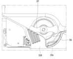
그리고, 상기 하우징(23)의 내부에는 제빙실(201)과 칠러룸(202)이 구획벽(207)에 의하여 상하로 구획되어 형성되며, 상기 제빙실(201)이 상기 칠러룸(202)의 상측에 위치할 수 있다. And, inside the housing (23), an ice making room (201) and a chiller room (202) are formed by being partitioned vertically by a partition wall (207), and the ice making room (201) can be located above the chiller room (202).
그리고, 상기 제빙실(201)에는, 얼음을 생성하는 아이스 메이커(24)와, 얼음을 저장하는 아이스 빈(25)이 수용될 수 있다. 상기 아이스 빈(25)은 상기 아이스 메이커(24)의 하측에 놓여서, 상기 아이스 메이커(24)로부터 낙하하는 얼음을 받아서 저장할 수 있다. And, in the ice making room (201), an ice maker (24) that creates ice and an ice bin (25) that stores ice can be accommodated. The ice bin (25) is placed below the ice maker (24) and can receive and store ice that falls from the ice maker (24).
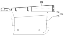
또한, 상기 하우징(23)의 측면에는 냉기 유입구(511)와 냉기 배출구(522)가 형성된다. 상세히, 상기 냉기 유입구(511)와 냉기 배출구(522)는, 상기 메인 도어(22)를 닫았을 때, 상기 인너 케이스(111)에 형성된 냉기 공급홀(111a)과 냉기 회수홀(111b)과 각각 연통한다. 상기 냉기 유입구(511)와 상기 냉기 배출구(522)는, 후술하게 될 도어 덕트 어셈블리(후술함)를 구성하는 냉기 공급 덕트(후술함)와 냉기 회수 덕트(후술함)에 각각 형성되는 부분이다.In addition, a cold air inlet (511) and a cold air outlet (522) are formed on the side of the housing (23). In detail, the cold air inlet (511) and the cold air outlet (522) are respectively connected to the cold air supply hole (111a) and the cold air recovery hole (111b) formed in the inner case (111) when the main door (22) is closed. The cold air inlet (511) and the cold air outlet (522) are parts formed in the cold air supply duct (described later) and the cold air recovery duct (described later) which constitute the door duct assembly (described later), which will be described later.
또한, 상기 서브 도어(21)는, 상기 메인 도어(22)의 전면에 회동 가능하게 결합된다. 상세히, 상기 서브 도어(21)의 회전축은 상기 메인 도어(22)의 회전축에 인접하는 위치에 형성되어, 개방 또는 폐쇄를 위한 회전 방향이 서로 동일하다. 다시 말하면, 상기 메인 도어(22)의 회전축과 상기 서브 도어(21)의 회전축은 동일한 측면(side surface)에 형성된다. In addition, the sub-door (21) is rotatably connected to the front of the main door (22). In detail, the rotation axis of the sub-door (21) is formed at a position adjacent to the rotation axis of the main door (22), so that the rotation directions for opening or closing are the same. In other words, the rotation axis of the main door (22) and the rotation axis of the sub-door (21) are formed on the same side surface.
그리고, 상기 서브 도어(21)의 전면에는 물과 얼음을 취출하기 위한 디스펜서(30)가 장착되며, 상기 디스펜서(30)의 구조에 대해서는 아래에서 도면을 참조하여 더욱 상세히 설명하도록 한다. In addition, a dispenser (30) for dispensing water and ice is mounted on the front of the sub door (21), and the structure of the dispenser (30) will be described in more detail with reference to the drawings below.
이와 같이, 상기 제빙실(201)은 상기 메인 도어(22)에 형성되고, 상기 디스펜서(30)는 상기 서브 도어(21)에 형성됨으로써, 하중 분산을 통한 도어 힌지의 안정성이 확보되는 장점이 있다. In this way, the ice making room (201) is formed in the main door (22) and the dispenser (30) is formed in the sub door (21), thereby providing the advantage of securing the stability of the door hinge through load distribution.
도 4는 도 3의 A 부분의 확대도이다.Figure 4 is an enlarged view of part A of Figure 3.
도 4를 참조하면, 본 발명의 실시예에 따른 냉장고(10)는, 한 쌍의 회동식 냉장실 도어(20) 중 적어도 어느 하나는 도어-인-도어 구조를 이룬다.Referring to FIG. 4, a refrigerator (10) according to an embodiment of the present invention has at least one of a pair of rotating refrigerator doors (20) having a door-in-door structure.
상세히, 상기 도어-인-도어 구조라 함은, 냉장고의 본체 또는 캐비닛에 설치된 저장 공간(예컨대 냉장실)을 개폐하며, 전면이 개구되는 별도의 저장 공간을 구비하는 메인 도어가 마련되고, 상기 메인 도어에 회동 가능하게 연결되어 상기 별도의 저장 공간의 개구된 전면을 개폐하는 서브 도어를 포함하는 도어 어셈블리를 의미하는 것으로 정의할 수 있다. 그리고, 상기 냉장고의 본체에 형성된 저장 공간을 개방하기 위하여 상기 메인 도어가 회전하는 방향과, 상기 메인 도어에 구비된 별도의 저장 공간을 개방하기 위하여 상기 서브 도어가 회전하는 방향이 동일할 수 있다. In detail, the door-in-door structure may be defined as a door assembly that opens and closes a storage space (e.g., a refrigerator) installed in a main body or cabinet of a refrigerator, and includes a main door having a separate storage space with an open front, and a sub-door that is rotatably connected to the main door to open and close the opened front of the separate storage space. In addition, the direction in which the main door rotates to open the storage space formed in the main body of the refrigerator and the direction in which the sub-door rotates to open the separate storage space provided in the main door may be the same.
더욱 상세히, 상기 메인 도어(22)는 상기 캐비닛(11)의 전면 좌측 또는 우측 가장자리에 회동 가능하게 연결되고, 상기 서브 도어(21)는 상기 메인 도어(22)의 전면 좌측 또는 우측 가장자리에 회동 가능하게 연결될 수 있다. 그리고, 상기 서브 도어(21)의 회전축이 형성되는 측방 가장자리와 상기 메인 도어(22)의 회전축이 형성되는 측방 가장자리는 동일하다. In more detail, the main door (22) may be rotatably connected to the front left or right edge of the cabinet (11), and the sub-door (21) may be rotatably connected to the front left or right edge of the main door (22). In addition, the lateral edge where the rotation axis of the sub-door (21) is formed and the lateral edge where the rotation axis of the main door (22) is formed are the same.
또한, 상기 메인 도어(22)에는 하우징(23)이 구비될 수 있고, 상기 하우징(23)의 내부에는 제빙실(201)과 칠러룸(202)이 형성될 수 있다. 그리고, 상기 제빙실(201)과 칠러룸(202)은 상기 서브 도어(21)를 개방하여 접근이 가능하도록, 상기 메인 도어(22)의 전면은 개구된다. 그리고, 상기 제빙실(201)의 전면 개구부에는 제빙실 도어(80)가 별도로 제공되어, 상기 서브 도어(21)가 개방되더라도 상기 제빙실(201)이 외부 공기에 노출되지 않도록 할 수 있다. In addition, the main door (22) may be provided with a housing (23), and an ice making room (201) and a chiller room (202) may be formed inside the housing (23). In addition, the front of the main door (22) is opened so that the ice making room (201) and the chiller room (202) can be accessed by opening the sub-door (21). In addition, an ice making room door (80) is provided separately at the front opening of the ice making room (201), so that even when the sub-door (21) is opened, the ice making room (201) is not exposed to the outside air.
또한, 상기 서브 도어(21)에는 상기 제빙실(201)에서 만들어진 얼음과 음용수를 취출하기 위한 디스펜서(30)가 설치된다. 상기 음용수는, 상기 캐비닛(11) 또는 상기 메인 도어(22)의 내부에 장착된 워터 탱크(26)로부터 공급될 수 있다. 상기 워터 탱크(26)는 급수 호스에 의하여 냉장고 외부의 급수원에 연결될 수 있다. In addition, a dispenser (30) for taking out ice and drinking water made in the ice making room (201) is installed in the sub door (21). The drinking water can be supplied from a water tank (26) installed inside the cabinet (11) or the main door (22). The water tank (26) can be connected to a water source outside the refrigerator by a water supply hose.
또한, 상기 메인 도어(22)의 하측에는 상기 워터 탱크(26)가 장착되기 위한 공간(203a)이 형성되며, 상기 워터 탱크(26)가 수용되는 공간은 상기 칠러룸(202)의 하측 영역에 형성된다. 그리고, 상기 워터 탱크(26)가 수용되는 공간은 워터 탱크 커버(203)에 의하여 선택적으로 개폐될 수 있다. In addition, a space (203a) for mounting the water tank (26) is formed on the lower side of the main door (22), and the space in which the water tank (26) is accommodated is formed in the lower area of the chiller room (202). In addition, the space in which the water tank (26) is accommodated can be selectively opened and closed by the water tank cover (203).
한편, 상기 디스펜서(30)는, 상기 서브 도어(21)에 형성된 디스펜서 장착을 위한 홀에 끼워지는 형태로 제공될 수 있다. 그리고, 상기 디스펜서(30)의 상단부는 상기 서브 도어(21)의 상단부로부터 하측으로 소정 거리 이격되는 지점에 위치할 수 있다. 상세히, 상기 디스펜서(30)의 상단부는 상기 서브 도어(21)를 상하로 2등분하는 가로면과 동일 선상에 놓이거나 그보다 약간 높은 지점에 형성될 수 있다. 그러나, 상기 디스펜서(30)의 설치 위치는 상기 메인 도어(22)에 형성된 제빙실(201)의 하단부 위치에 따라 달라질 수 있다. Meanwhile, the dispenser (30) may be provided in a form that is fitted into a hole for mounting the dispenser formed in the sub-door (21). In addition, the upper part of the dispenser (30) may be positioned at a point spaced a predetermined distance downward from the upper part of the sub-door (21). In detail, the upper part of the dispenser (30) may be formed at a point that is located on the same line as the horizontal plane that divides the sub-door (21) into two parts, or slightly higher than that. However, the installation position of the dispenser (30) may vary depending on the lower part position of the ice-making chamber (201) formed in the main door (22).
상세히, 상기 디스펜서(30)는, 프런트 케이싱(31), 리어 케이싱(32), 취출 버튼(33), 마이크로 스위치(34), 물꼭지(35)(또는 음용수 취출구), 아우터 퍼넬(outer funnel)(36), 인너 퍼넬(inner funnel)(37), 덕트 캡(38) 및 디스차지 덕트(discharge duct)(39) 를 포함할 수 있다. In detail, the dispenser (30) may include a front casing (31), a rear casing (32), a discharge button (33), a micro switch (34), a water tap (35) (or a drinking water discharge port), an outer funnel (36), an inner funnel (37), a duct cap (38), and a discharge duct (39).
상기 아우터 퍼넬(36)과 인너 퍼넬(37)은 별도의 부품들이 결합되는 형태일 수도 있고, 단일체로 사출 성형될 수도 있다. 상기 아우터 퍼넬(36)과 인너 퍼넬(37)의 결합체를 아이스 퍼넬(ice funnel)로 정의할 수 있다. The above outer funnel (36) and inner funnel (37) may be formed by combining separate parts, or may be injection-molded as a single body. The combination of the outer funnel (36) and inner funnel (37) may be defined as an ice funnel.
또한, 상기 프런트 케이싱(31)과 리어 케이싱(32)의 결합체는 디스펜서 케이싱으로 정의될 수 있다. Additionally, the combination of the front casing (31) and the rear casing (32) can be defined as a dispenser casing.
더욱 상세히, 상기 프런트 케이싱(31)은, 상기 서브 도어(21)에 형성된 디스펜서 장착홀에 삽입되어 상기 서브 도어(21)에 고정된다. 그리고, 상기 프런트 케이싱(31)은 후방으로 소정 깊이 함몰되어, 물 또는 얼음을 받는 용기가 수용될 수 있다. 그리고, 상기 리어 케이싱(32)은 상기 프런트 케이싱(31)의 후측에 결합되는 형태로 상기 서브 도어(21)에 고정될 수 있다. 그리고, 상기 디스펜서(30) 부분에 해당하는 상기 서브 도어(21)의 배면에는 디스펜서 라이너(211)가 돌출 형성될 수 있다. 그리고, 상기 리어 케이싱(32)과 상기 디스펜서 라이너(211) 사이에는 단열재가 발포 충진될 수 있다. In more detail, the front casing (31) is inserted into a dispenser mounting hole formed in the sub-door (21) and fixed to the sub-door (21). In addition, the front casing (31) is sunken to a predetermined depth toward the rear so that a container for receiving water or ice can be accommodated. In addition, the rear casing (32) can be fixed to the sub-door (21) in a form coupled to the rear side of the front casing (31). In addition, a dispenser liner (211) can be formed protruding on the rear surface of the sub-door (21) corresponding to the dispenser (30) portion. Insulating material can be foam-filled between the rear casing (32) and the dispenser liner (211).
또한, 상기 취출 버튼(33)은 상기 프런트 케이싱(31)에 전후 방향으로 틸팅 가능하게 결합될 수 있다. 그리고, 상기 취출 버튼(33)의 후측에 해당하는 상기 리어 케이싱(32)에는 상기 마이크로 스위치(34)가 장착된다. 따라서, 사용자가 상기 취출 버튼(33)을 누르면 상기 마이크로 스위치(34)에 접촉하여 물과 얼음 중 어느 하나 또는 모두의 취출 신호를 발생시킬 수 있다. In addition, the ejection button (33) can be tiltably coupled to the front casing (31) in the forward and backward directions. In addition, the micro switch (34) is mounted on the rear casing (32) corresponding to the rear side of the ejection button (33). Accordingly, when a user presses the ejection button (33), the micro switch (34) is contacted to generate an ejection signal of either or both of water and ice.
상기 취출 버튼(33)은, 도시된 바와 같이 하나의 버튼으로 제공되고, 상기 디스펜서(30)의 상측에 해당하는 상기 서브 도어(21)의 전면에 장착되는 컨트롤 패널(300)을 통하여 물 취출 모드와 얼음 취출 모드를 선택하도록 설계될 수 있다. 즉, 사용자가 상기 컨트롤 패널(300)에 구비되는 모드 선택 버튼을 눌러 물 또는 얼음 취출 모드 중 어느 하나를 선택하고, 상기 취출 버튼(33)을 누르면, 물과 얼음 중 어느 하나가 취출된다. The above-described extraction button (33) may be provided as a single button as illustrated, and may be designed to select a water extraction mode and an ice extraction mode through a control panel (300) mounted on the front of the sub-door (21) corresponding to the upper side of the dispenser (30). That is, when a user presses the mode selection button provided on the control panel (300) to select either the water or ice extraction mode, and presses the extraction button (33), either the water or ice is extracted.
다른 방법으로서, 상기 디스펜서(30)에 물취출 버튼과 얼음 취출 버튼이 상하 또는 좌우 방향으로 설치되어, 사용자가 원하는 버튼을 누르도록 할 수도 있다. Alternatively, the water dispensing button and the ice dispensing button may be installed in the dispenser (30) in an up/down or left/right direction so that the user can press the desired button.
한편, 상기 물꼭지(35)는 상기 물취출 버튼(33)의 상측에 해당하는 상기 프런트 케이싱(31)의 어느 지점에서 전방으로 돌출될 수 있다. 그리고, 상기 아이스 퍼넬은 상기 프런트 케이싱(31)의 상측에서 전후 방향으로 틸팅 가능하게 설치될 수 있다. Meanwhile, the water tap (35) can protrude forward at a point of the front casing (31) corresponding to the upper side of the water discharge button (33). And, the ice funnel can be installed so as to be tiltable in the forward and backward direction on the upper side of the front casing (31).
또한, 상기 구획벽(207)의 내부에는 얼음 배출을 안내하는 가이드 덕트(207d)가 연장 형성되며, 상기 가이드 덕트(207d)의 입구단은 상기 제빙실(201)의 바닥 전방에 형성된 얼음 토출구(207a : 도 6 참조)와 연통한다. 그리고, 상기 가이드 덕트(207d)의 출구단은 상기 구획벽(207)의 저면에 노출되고, 상기 서브 도어(21)가 닫힌 상태에서 상기 디스차지 덕트(39)의 입구단에 밀착된다. 도시된 바와 같이, 상기 디스차지 덕트(39)의 입구단 가장자리와, 상기 가이드 덕트(207d)의 출구단 가장자리에는 냉기 실링을 위한 가스켓(391,207e)이 각각 장착될 수 있다. 그리고, 상기 서브 도어(21)가 닫힌 상태에서 이들 가스켓은 서로 밀착되어, 상기 가이드 덕트(207d)와 디스차지 덕트(39)는 상기 제빙실(201)하고만 연통하고, 상기 칠러룸(202)과는 연통하지 않도록 할 수 있다. In addition, a guide duct (207d) for guiding ice discharge is formed extending inside the partition wall (207), and the inlet end of the guide duct (207d) communicates with an ice discharge port (207a: see FIG. 6) formed at the front of the bottom of the ice making room (201). In addition, the outlet end of the guide duct (207d) is exposed to the bottom surface of the partition wall (207) and is in close contact with the inlet end of the discharge duct (39) when the sub-door (21) is closed. As illustrated, gaskets (391, 207e) for cold air sealing may be respectively mounted on the edge of the inlet end of the discharge duct (39) and the edge of the outlet end of the guide duct (207d). And, when the sub-door (21) is closed, these gaskets are in close contact with each other so that the guide duct (207d) and the discharge duct (39) communicate only with the ice making room (201) and not with the chiller room (202).
그리고, 상기 디스차지 덕트(39)의 출구단 쪽에는 상기 아이스 퍼넬이 회동 가능하게 연결되고, 상기 아이스 퍼넬의 출구단은 상기 프런트 케이싱(31)의 상단에 형성된 개구부와 연통하여 디스펜서(30) 외부로 노출된다. And, the ice funnel is rotatably connected to the outlet end of the discharge duct (39), and the outlet end of the ice funnel is exposed to the outside of the dispenser (30) by communicating with an opening formed at the top of the front casing (31).
또한, 상기 디스차지 덕트(39)의 출구단은 상기 덕트 캡(38)에 의하여 선택적으로 개폐되며, 상기 덕트 캡(38)은 상기 디스펜서(30) 내부에 회동 가능하게 설치된다. 상기 덕트 캡(38)이 회동하여 상기 디스차지 덕트(39)의 출구단이 개방되면, 상기 아이스 빈(25)에 저장된 얼음이 디스펜서(30) 외부로 배출된다. In addition, the outlet of the discharge duct (39) is selectively opened and closed by the duct cap (38), and the duct cap (38) is rotatably installed inside the dispenser (30). When the duct cap (38) rotates to open the outlet of the discharge duct (39), the ice stored in the ice bin (25) is discharged outside the dispenser (30).
또한, 상기 아이스 퍼넬(37)은 상기 얼음 취출 버튼(36)과 한 몸으로 이루어질 수 있다. Additionally, the ice funnel (37) can be formed as one body with the ice extraction button (36).
한편, 본 발명의 실시예에서는, 상기 제빙실(201) 내부에 아이스 메이커(24)와 아이스 빈(25)이 모두 수용되는 구조로 한정하여 설명하고 있으나, 반드시 이에 제한되는 것은 아님을 밝혀둔다. Meanwhile, in the embodiment of the present invention, the structure in which both the ice maker (24) and the ice bin (25) are accommodated inside the ice making room (201) is described as being limited to this, but it should be noted that it is not necessarily limited thereto.
다른 가능한 실시예로서, 상기 제빙실(201) 내부에는 상기 아이스 메이커(24)만 수용되고, 상기 아이스 빈(25)은 상기 서브 도어(21)의 배면에 구비되는 구조도 가능하다. 이 경우, 상기 아이스 빈(25)은 상기 디스펜서(30)의 상측, 구체적으로는 상기 디스차지 덕트(39)의 상측에 놓이게 된다. 그리고, 상기 서브 도어(21)의 배면에는 상기 아이스 빈(25)을 수용하기 위한 별도의 단열벽 구조가 설치될 수 있다. As another possible embodiment, only the ice maker (24) is accommodated inside the ice making room (201), and the ice bin (25) is provided on the back surface of the sub door (21). In this case, the ice bin (25) is placed above the dispenser (30), specifically, above the discharge duct (39). In addition, a separate insulating wall structure for accommodating the ice bin (25) may be installed on the back surface of the sub door (21).
도 5는 서브 도어가 개방된 상태의 도어-인-도어 어셈블리를 보여주는 사시도이고, 도 6은 상기 도어-인-도어 어셈블리의 전방 분해 사시도이고, 도 7은 상기 도어-인-도어 어셈블리의 후방 분해 사시도이다.FIG. 5 is a perspective view showing the door-in-door assembly with the sub-door open, FIG. 6 is a front exploded perspective view of the door-in-door assembly, and FIG. 7 is a rear exploded perspective view of the door-in-door assembly.
도 5 내지 도 7을 참조하면, 본 발명의 실시예에 따른 냉장고(10)의 냉장실 도어(20)를 구성하는 도어 인 도어 어셈블리는, 메인 도어(22)와 서브 도어(21)로 이루어진다. Referring to FIGS. 5 to 7, the door-in-door assembly constituting the refrigerator door (20) of the refrigerator (10) according to the embodiment of the present invention is composed of a main door (22) and a sub-door (21).
상세히, 상기 서브 도어(21)와 메인 도어(22)는 상기 힌지 어셈블리(40)에 의하여 상기 캐비닛(11)에 회동 가능하게 결합될 수 있다.In detail, the sub door (21) and the main door (22) can be rotatably connected to the cabinet (11) by the hinge assembly (40).
더욱 상세히, 상기 힌지 어셈블리(40)는 상기 캐비닛(11)과 상기 메인 도어(22)를 연결하는 메인 도어 힌지 유닛(또는 제 1 도어 힌지 유닛)과, 상기 메인 도어(22)와 상기 서브 도어(21)를 연결하는 서브 도어 힌지 유닛(또는 제 2 도어 힌지 유닛)을 포함한다.In more detail, the hinge assembly (40) includes a main door hinge unit (or first door hinge unit) connecting the cabinet (11) and the main door (22), and a sub-door hinge unit (or second door hinge unit) connecting the main door (22) and the sub-door (21).
상세히, 상기 메인 도어 힌지 유닛은, 상기 캐비닛(11)과 상기 메인 도어(22)의 상면을 연결하는 메인 도어 어퍼 힌지 유닛(또는 제 1 도어 어퍼 힌지 유닛)(41)과, 상기 캐비닛(11)과 상기 메인 도어(22)의 저면을 연결하는 메인 도어 로어 힌지 유닛(또는 제 1 도어 로어 힌지 유닛)을 포함한다.In detail, the main door hinge unit includes a main door upper hinge unit (or first door upper hinge unit) (41) connecting the upper surface of the cabinet (11) and the main door (22), and a main door lower hinge unit (or first door lower hinge unit) connecting the lower surface of the cabinet (11) and the main door (22).
또한, 상기 서브 도어 힌지 유닛은, 상기 메인 도어(22)와 상기 서브 도어(21)의 상면을 연결하는 서브 도어 어퍼 힌지 유닛(또는 제 2 도어 어퍼 힌지 유닛)(42)과, 상기 메인 도어(22)와 상기 서브 도어(21)의 저면을 연결하는 서브 도어 로어 힌지 유닛(또는 제 2 도어 로어 힌지 유닛)을 포함한다. In addition, the sub-door hinge unit includes a sub-door upper hinge unit (or second door upper hinge unit) (42) connecting the upper surface of the main door (22) and the sub-door (21), and a sub-door lower hinge unit (or second door lower hinge unit) connecting the lower surface of the main door (22) and the sub-door (21).
또한, 도시된 바와 같이, 상기 서브 도어(21)를 개방하면, 상기 디스차지 덕트(39)의 입구단이 외부로 노출되고, 상기 디스차지 덕트(39)의 입구단 가장자리에는 가스켓(391)이 둘러진다. In addition, as illustrated, when the sub-door (21) is opened, the inlet end of the discharge duct (39) is exposed to the outside, and a gasket (391) is surrounded around the edge of the inlet end of the discharge duct (39).
상기 디스펜서 라이너(211)가 상기 서브 도어(21)의 배면으로부터 후방으로 더 돌출되고, 상기 디스펜서 라이너(211)의 상면에 상기 디스차지 덕트(39)의 입구단이 형성될 수 있다.The above dispenser liner (211) may further protrude rearwardly from the back surface of the sub-door (21), and the inlet end of the discharge duct (39) may be formed on the upper surface of the dispenser liner (211).
또한, 도 4에 도시된 바와 같이, 상기 디스차지 덕트(39)의 입구단이 형성되는 상기 디스펜서 라이너(211)의 상면은 후방으로 갈수록 하향 경사지게 형성된다. 그리고, 상기 가이드 덕트(207d)의 출구단이 형성되는 상기 구획벽(207)의 저면도 상기 디스펜서 라이너(211) 상면의 경사 각도에 대응하는 각도로 경사지게 형성된다. 그 결과, 상기 서브 도어(21)가 닫힐 때, 상기 디스차지 덕트(39)의 입구단에 둘러지는 가스켓(391)과 상기 가이드 덕트(207d)의 출구단에 둘러지는 가스켓(207e)이 밀착되는 과정에서 발생할 수 있는 전단력(shearing force)에 의한 밀림 현상을 최소화할 수 있다. In addition, as illustrated in FIG. 4, the upper surface of the dispenser liner (211) where the inlet end of the discharge duct (39) is formed is formed to slope downward as it goes toward the rear. In addition, the lower surface of the partition wall (207) where the outlet end of the guide duct (207d) is formed is also formed to slope at an angle corresponding to the inclination angle of the upper surface of the dispenser liner (211). As a result, when the sub-door (21) is closed, the pushing phenomenon due to the shearing force that may occur during the process in which the gasket (391) surrounding the inlet end of the discharge duct (39) and the gasket (207e) surrounding the outlet end of the guide duct (207d) are brought into close contact can be minimized.
또한, 상기 서브 도어(21)의 배면에는 실링 부재(210)가 둘러진다. 상기 실링 부재(210)는, 상기 서브 도어(21)가 닫힌 상태에서, 상기 메인 도어(22)의 전면 에 형성되는 개구부의 가장자리에 밀착된다. 그 결과, 서브 도어(21)와 메인 도어(22) 사이의 틈새로 유입되는 외부 공기가 상기 하우징(23) 내부로 유입되거나, 상기 하우징(23) 내부의 냉기가 외부로 누설되는 것을 차단할 수 있다. In addition, a sealing member (210) is surrounded on the back surface of the sub-door (21). The sealing member (210) is in close contact with the edge of the opening formed on the front surface of the main door (22) when the sub-door (21) is closed. As a result, external air flowing into the gap between the sub-door (21) and the main door (22) can be prevented from flowing into the housing (23) or cold air inside the housing (23) can be prevented from leaking to the outside.
상세히, 상기 하우징(23)은, 인너 하우징(231)과, 상기 인너 하우징(231)의 후방에 결합되는 아우터 하우징(232)를 포함할 수 있다. 그리고, 상기 인너 하우징(231)의 외부 측면(outer surface)에는 냉기 이동을 위한 도어 덕트 어셈블리(50:도 8 참조)가 설치되고, 상기 도어 덕트 어셈블리(50)는 상기 아우터 하우징(232)에 의하여 덮여서 외부 노출이 차단된다. 단, 상기 덕트 어셈블리(50)의 냉기 유입구(511)와 냉기 배출구(522)는 상기 아우터 하우징(232)의 측면을 관통하여 외부로 노출된다. 상기 도어 덕트 어셈블리(50)는 도어측 냉기 덕트 어셈블리로 정의될 수 있으며, 상기 도어 덕트 어셈블리(50)의 구조에 대해서는 아래에서 도면을 참조하여 더욱 상세히 설명한다. In detail, the housing (23) may include an inner housing (231) and an outer housing (232) coupled to the rear of the inner housing (231). In addition, a door duct assembly (50: see FIG. 8) for cold air movement is installed on the outer surface of the inner housing (231), and the door duct assembly (50) is covered by the outer housing (232) to block external exposure. However, the cold air inlet (511) and the cold air outlet (522) of the duct assembly (50) penetrate the side surface of the outer housing (232) and are exposed to the outside. The door duct assembly (50) may be defined as a door-side cold air duct assembly, and the structure of the door duct assembly (50) will be described in more detail below with reference to the drawings.
한편, 상기 아우터 하우징(232)의 배면에는 하나 또는 다수의 도어 바스켓(205)이 장착될 수 있다. 그리고, 상기 칠러룸(202)의 배면에 해당하는 상기 하우징(23) 부분은 개구되고, 상기 개구되는 하우징(23) 부분은 칠러룸 커버(208)에 의하여 선택적으로 개폐될 수 있다. 상기 칠러룸 커버(208)의 측단부는 상기 하우징(23)에 회동 가능하게 연결될 수 있다. 그리고, 상기 칠러룸(202)의 전면 개구부는 상기 서브 도어(21)에 의하여 개폐된다. Meanwhile, one or more door baskets (205) may be mounted on the back surface of the outer housing (232). In addition, a portion of the housing (23) corresponding to the back surface of the chiller room (202) is opened, and the opened portion of the housing (23) may be selectively opened and closed by the chiller room cover (208). A side end of the chiller room cover (208) may be rotatably connected to the housing (23). In addition, the front opening of the chiller room (202) is opened and closed by the sub door (21).
또한, 상기 인너 하우징(231)의 내부는, 상술한 바와 같이, 구획벽(207)에 의하여 상측의 제빙실(201)과 하측의 칠러룸(202)으로 구획될 수 있다. 그리고, 상기 제빙실(201)의 전면 개구부는 제빙실 도어(80)에 의하여 개폐될 수 있다. 그리고, 상기 제빙실 도어(80)는 상기 제빙실(201)의 전면 개구부의 측면 가장자리에 회동 가능하게 힌지 결합될 수 있다. In addition, the interior of the inner housing (231) may be partitioned into an upper ice-making room (201) and a lower chiller room (202) by a partition wall (207), as described above. In addition, the front opening of the ice-making room (201) may be opened and closed by an ice-making room door (80). In addition, the ice-making room door (80) may be rotatably hinged to a side edge of the front opening of the ice-making room (201).
한편, 상기 구획벽(207)에는 얼음 토출구(207a)가 형성될 수 있다. 상세히, 상기 얼음 토출구(207a)는 상기 구획벽(207)의 후단부보다 전단부에 더 가깝게 위치될 수 있다. 구체적으로, 상기 얼음 토출구(207a)를 전후 방향으로 이등분하는 수직면은, 상기 구획벽(207)을 전후 방향으로 이등분하는 수직면보다 전방에 위치될 수 있다. 그러면, 상기 얼음 토출구(207a)에 밀착되는 상기 디스차지 덕트(39)의 경사각이 감소될 수 있고, 그 결과 상기 디스펜서(30)의 전후 방향 폭이 감소될 수 있다. Meanwhile, an ice discharge port (207a) may be formed in the partition wall (207). In detail, the ice discharge port (207a) may be positioned closer to the front end than the rear end of the partition wall (207). Specifically, a vertical plane dividing the ice discharge port (207a) in the front-back direction may be positioned forward of a vertical plane dividing the partition wall (207) in the front-back direction. Then, the angle of inclination of the discharge duct (39) that is in close contact with the ice discharge port (207a) may be reduced, and as a result, the width of the dispenser (30) in the front-back direction may be reduced.
상기 디스차지 덕트(39)의 경사각이라 함은 수직면과 디스차지 덕트(39)가 이루는 각도를 의미하는 것으로서, 상기 얼음 토출구(207a)가 상기 구획벽(207)의 전단부에 더 가깝게 위치하면, 상기 디스차지 덕트(39)가 수직에 가깝게 경사지게 된다.The angle of inclination of the discharge duct (39) refers to the angle formed between the vertical plane and the discharge duct (39). When the ice discharge port (207a) is located closer to the front end of the partition wall (207), the discharge duct (39) is inclined closer to the vertical.
상세히, 서브 도어(21)가 닫히면, 상기 디스펜서(30)는 상기 칠러룸(202) 내부에 수용된다. 그리고, 상기 디스펜서(30)의 두께가 작아질수록 상기 칠러룸(202)의 용적이 커지므로, 상기 디스차지 덕트(39)의 경사각은 작을수록 유리하다고 할 수 있다. In detail, when the sub-door (21) is closed, the dispenser (30) is accommodated inside the chiller room (202). And, as the thickness of the dispenser (30) decreases, the volume of the chiller room (202) increases, so it can be said that the smaller the angle of inclination of the discharge duct (39), the more advantageous it is.
그리고, 상기 얼음 토출구(207a)를 좌우 방향으로 이등분하는 수직면은, 상기 구획벽(207)을 좌우 방향으로 이등분하는 수직면과 일치할 수 있다. And, the vertical plane that divides the ice discharge port (207a) into two halves in the left-right direction can coincide with the vertical plane that divides the partition wall (207) into two halves in the left-right direction.
그리고, 상기 구획벽(207) 내부에는 상기 가이드 덕트(207d)가 장착되고, 상기 가이드 덕트(207d)의 입구단이 상기 얼음 토출구(207a)와 연통한다. 상기 얼음 토출구(207a)가 상기 구획벽(207)의 전단부, 즉 상기 제빙실(201)의 전단부에 가까울수록, 수직면으로부터 상기 가이드 덕트(207d)의 기울어진 각도도 작아질 수 있다. And, the guide duct (207d) is mounted inside the partition wall (207), and the inlet end of the guide duct (207d) is connected to the ice discharge port (207a). As the ice discharge port (207a) is closer to the front end of the partition wall (207), that is, the front end of the ice making room (201), the angle at which the guide duct (207d) is tilted from the vertical plane can also be reduced.
또한, 상기 구획벽(207)에는 상기 제빙실(201)과 칠러룸(202)이 유동적으로(fluidly) 연통하도록 연통홀(207b)이 형성될 수 있다. 상기 연통홀(207b)은 상기 얼음 토출구(207a)와의 간섭을 피하도록, 상기 구획벽(207)의 좌측 또는 우측 가장자리에 위치할 수 있고, 상기 얼음 토출구(207a)로부터 후측으로 소정 간격 이격되는 지점에 형성될 수 있다. 바람직하게는 상기 도어 덕트 어셈블리(50)가 장착되는 인너 하우징(231)의 측면과 반대되는 측면에 가까운 지점에 형성되는 것이 좋다. 그러면, 상기 도어 덕트 어셈블리(50)를 통하여 제빙실(201)로 토출되는 냉기가 낙하하는 지점에 상기 연통홀(207b)이 형성됨으로써, 냉기가 상기 칠러룸(202)으로 용이하게 공급될 수 있다. 상기 연통홀(207b) 내부에는 댐퍼 어셈블리가 장착되어, 상기 제빙실(201)로부터 상기 칠러룸(202)으로 공급되는 냉기의 양이 조절되도록 할 수 있다. 즉, 상기 칠러룸(202)이 상기 제빙실(201) 온도보다는 높고 상기 냉장실 온도보다는 낮은 온도로 유지되도록, 상기 댐퍼 어셈블리에 의하여 제어될 수 있다. In addition, a communication hole (207b) may be formed in the partition wall (207) so that the ice making room (201) and the chiller room (202) can be fluidly communicated. The communication hole (207b) may be positioned at the left or right edge of the partition wall (207) to avoid interference with the ice discharge port (207a), and may be formed at a point spaced a predetermined distance rearward from the ice discharge port (207a). Preferably, it is formed at a point close to a side opposite to the side of the inner housing (231) on which the door duct assembly (50) is mounted. Then, since the communication hole (207b) is formed at a point where the cold air discharged to the ice making room (201) through the door duct assembly (50) falls, the cold air can be easily supplied to the chiller room (202). A damper assembly is mounted inside the above-mentioned communication hole (207b) so that the amount of cold air supplied from the ice making room (201) to the chiller room (202) can be controlled. That is, the chiller room (202) can be controlled by the damper assembly so that it is maintained at a temperature higher than the temperature of the ice making room (201) and lower than the temperature of the refrigerator room.
도 8은 아우터 하우징이 제거된 메인 도어의 배면 사시도이고, 도 9는 도 8에 개시되는 메인 도어의 분해 사시도이며, 도 10은 도어 덕트 어셈블리의 분해 사시도이다.FIG. 8 is a rear perspective view of the main door with the outer housing removed, FIG. 9 is an exploded perspective view of the main door disclosed in FIG. 8, and FIG. 10 is an exploded perspective view of the door duct assembly.
도 8 내지 도 10을 참조하면, 상기 메인 도어(22)의 배면에 결합되는 상기 하우징(23)은 인너 하우징(231)과 아우터 하우징(232)으로 이루어질 수 있고, 상기 인너 하우징(231)의 외부 측면과 상기 아우터 하우징(232)의 내부 측면 사이 공간에는 상기 도어 덕트 어셈블리(50)가 장착될 수 있다. 그리고, 상기 인너 하우징(231)과 아우터 하우징(232) 사이의 공간에는 단열재가 발포 충진되어 냉기 누설을 방지할 수 있다. Referring to FIGS. 8 to 10, the housing (23) coupled to the back surface of the main door (22) may be composed of an inner housing (231) and an outer housing (232), and the door duct assembly (50) may be mounted in the space between the outer side of the inner housing (231) and the inner side of the outer housing (232). In addition, an insulating material may be foam-filled in the space between the inner housing (231) and the outer housing (232) to prevent cold air leakage.
또한, 상기 도어 덕트 어셈블리(50)가 장착되는 상기 인너 하우징(231)의 측면에는 냉기가 유입 또는 유출되기 위한 냉기홀들이 형성될 수 있다.Additionally, cold air holes for allowing cold air to flow in or out can be formed on the side of the inner housing (231) on which the door duct assembly (50) is mounted.
상세히, 상기 인너 하우징(231)의 측면에 형성되는 냉기홀들은, 냉기 유입구(231a)와, 제빙실측 냉기 배출구(231b), 및 칠러룸측 냉기 배출구(231c)를 포함할 수 있다. In detail, the cold air holes formed on the side of the inner housing (231) may include a cold air inlet (231a), a cold air outlet (231b) on the ice making room side, and a cold air outlet (231c) on the chiller room side.
더욱 상세히, 상기 냉기 유입구(231a)는, 상기 제빙실(201)을 정의하는 상기 인너 하우징(231)의 측면에 형성되고, 상기 제빙실(201)의 상측 공간에 위치할 수 있다. In more detail, the cold air inlet (231a) may be formed on a side of the inner housing (231) defining the ice making room (201) and may be located in the upper space of the ice making room (201).
그리고, 상기 제빙실측 냉기 배출구(231b)는 상기 제빙실(201)을 정의하는 상기 인너 하우징(231)의 측면에 형성되고, 상기 제빙실(201)의 하측부에 위치할 수 있다. In addition, the ice making room side cold air discharge port (231b) is formed on the side of the inner housing (231) defining the ice making room (201) and can be located at the lower part of the ice making room (201).
또한, 상기 칠러룸측 냉기 배출구(231c)는, 상기 칠러룸(202)을 정의하는 상기 인너 하우징(231)의 측면에 형성되고, 상기 칠러룸(201)의 하측부에 위치할 수 있다. In addition, the chiller room side cold air discharge port (231c) may be formed on the side of the inner housing (231) defining the chiller room (202) and may be located at the lower part of the chiller room (201).
한편, 상기 도어 덕트 어셈블리(50)는, 냉기 공급 덕트(51)와 냉기 회수 덕트(52)를 포함할 수 있다. 그리고, 상기 냉기 공급 덕트(51)와 상기 냉기 회수 덕트(52)는 상기 인너 하우징(231)의 측방향으로 중첩되게 배치될 수 있다.Meanwhile, the door duct assembly (50) may include a cold air supply duct (51) and a cold air recovery duct (52). In addition, the cold air supply duct (51) and the cold air recovery duct (52) may be arranged to overlap each other in the lateral direction of the inner housing (231).
상기 냉기 공급 덕트(51)는 상기 캐비닛(11)의 측면에서 연장되는 상기 공급 덕트(181)와 연결되어, 증발실(116) 냉기를 상기 제빙실(201)로 공급해 주는 덕트이다. 그리고, 상기 냉기 회수 덕트(52)는, 상기 캐비닛(11)의 측면에서 연장되는 상기 회수 덕트(182)와 연결되어, 상기 제빙실(201)과 상기 칠러룸(202)으로부터 배출되는 냉기를 상기 냉동실(115)로 보내주는 덕트이다.The above cold air supply duct (51) is a duct that is connected to the supply duct (181) extending from the side of the cabinet (11) and supplies cold air from the evaporation chamber (116) to the ice making chamber (201). In addition, the cold air recovery duct (52) is a duct that is connected to the recovery duct (182) extending from the side of the cabinet (11) and sends cold air discharged from the ice making chamber (201) and the chiller room (202) to the freezer chamber (115).
상세히, 상기 냉기 공급 덕트(51)의 외측면 하단부에는 상기 냉기 유입구(511)가 형성되고, 상기 냉기 유입구(511)는 상기 메인 도어(22)가 닫혔을 때 상기 인너 케이스(111)의 측면에 형성된 상기 냉기 공급홀(111a)과 연통한다. In detail, the cold air inlet (511) is formed at the lower end of the outer surface of the cold air supply duct (51), and the cold air inlet (511) communicates with the cold air supply hole (111a) formed on the side of the inner case (111) when the main door (22) is closed.
그리고, 상기 냉기 공급 덕트(51)의 내측면 상단부에는 냉기 토출구(512)가 형성되고, 상기 냉기 토출구(512)는 상기 냉기 유입구(231a)와 연통한다. And, a cold air discharge port (512) is formed at the upper part of the inner side of the cold air supply duct (51), and the cold air discharge port (512) communicates with the cold air inlet port (231a).
또한, 상기 냉기 회수 덕트(52)의 내측면 상단부에는 상부 냉기 유입구(521)가 형성되고, 상기 상부 냉기 유입구(521)는 상기 제빙실측 냉기 배출구(231b)와 연통한다. In addition, an upper cold air inlet (521) is formed at the upper part of the inner side of the cold air recovery duct (52), and the upper cold air inlet (521) communicates with the cold air discharge port (231b) on the ice making room side.
그리고, 상기 냉기 회수 덕트(52)의 내측면 하단부에는 하부 냉기 유입구(523)가 형성되고, 상기 하부 냉기 유입구(523)는 상기 칠러룸측 냉기 배출구(231c)와 연통한다. In addition, a lower cold air inlet (523) is formed at the lower end of the inner side of the cold air recovery duct (52), and the lower cold air inlet (523) communicates with the cold air discharge port (231c) on the chiller room side.
그리고, 상기 냉기 회수 덕트(52)의 외측면 하단부에는 상기 냉기 배출구(522)가 형성되고, 상기 냉기 배출구(522)는, 상기 메인 도어(22)가 닫혔을 때 상기 인너 케이스(111)의 측면에 형성된 상기 냉기 회수홀(111b)과 연통한다. And, the cold air discharge port (522) is formed at the lower end of the outer surface of the cold air recovery duct (52), and the cold air discharge port (522) communicates with the cold air recovery hole (111b) formed on the side of the inner case (111) when the main door (22) is closed.
여기서, 상기 상부 냉기 유입구(521)는 제 1 입구단으로 정의되고, 상기 하부 냉기 유입구(522)는 제 2 입구단으로 정의될 수 있다. Here, the upper cold air inlet (521) may be defined as a first inlet, and the lower cold air inlet (522) may be defined as a second inlet.
도 11은 도 6의 XI-XI를 따라 절개되는 부분 종단면도이다. Fig. 11 is a partial cross-sectional view taken along line XI-XI of Fig. 6.
도 11을 참조하면, 상기 제빙실(201)과 상기 칠러룸(202) 사이에는 상기 구획벽(207)이 형성되고, 상기 구획벽(207) 내부에는 상기 가이드 덕트(207d)와 댐퍼 어셈블리(200)가 장착된다. Referring to FIG. 11, a partition wall (207) is formed between the ice making room (201) and the chiller room (202), and the guide duct (207d) and the damper assembly (200) are mounted inside the partition wall (207).
상세히, 상기 가이드 덕트(207d)의 출구단이 형성되는 상기 구획벽(207)의 저면은 하향 경사진다. 그리고, 상기 가이드 덕트(207d)의 측방향 및 후측으로 이격되는 지점에는 상기 연통홀(207b)이 상기 구획벽(207)을 관통하여 형성된다. 그리고, 상기 연통홀(207b) 내부에는 댐퍼 어셈블리(200)가 장착되어, 상기 제빌실(201)로부터 상기 칠러룸(202)으로 공급되는 냉기의 양이 조절되도록 할 수 있다. In detail, the bottom surface of the partition wall (207) where the outlet of the guide duct (207d) is formed is inclined downward. In addition, the communication hole (207b) is formed by penetrating the partition wall (207) at a point spaced laterally and rearwardly from the guide duct (207d). In addition, a damper assembly (200) is mounted inside the communication hole (207b) so that the amount of cold air supplied from the evaporation chamber (201) to the chiller room (202) can be controlled.
한편, 상기 구획벽(207)은, 도시된 바와 같이, 인너 하우징(231)과 아우터 하우징(232) 사이에 마련되는 공간에 발포폼이 충진되어, 하우징(23)의 일부분으로 형성될 수도 있지만, 별도의 부품으로 제공되어 상기 인너 하우징(231) 내부에 결합될 수도 있다. Meanwhile, the partition wall (207), as illustrated, may be formed as a part of the housing (23) by filling the space provided between the inner housing (231) and the outer housing (232) with foam, but may also be provided as a separate part and joined to the inside of the inner housing (231).
도 12는 제빙실과 칠러룸을 구획하는 구획벽 내부에 설치되는 댐퍼 어셈블리의 분해 사시도이다.Figure 12 is an exploded perspective view of a damper assembly installed inside a partition wall dividing an ice room and a chiller room.
도 12를 참조하면, 상기 댐퍼 어셈블리(200)는, 아우터 박스(200a)와, 미들 박스(200b), 인너 박스(200c), 댐퍼(200d), 및 토출 그릴(200f)을 포함할 수 있다. Referring to FIG. 12, the damper assembly (200) may include an outer box (200a), a middle box (200b), an inner box (200c), a damper (200d), and a discharge grill (200f).
상세히, 상기 아우터 박스(200a), 미들 박스(200b), 및 인너 박스(200c)의 상면에는 상기 연통홀(207b)에 대응하는 냉기홀들(200g,200h,200i)이 각각 형성된다. 그리고, 상기 미들 박스(200b)는 스티로폼과 같은 단열 부재일 수 있다. In detail, cold holes (200g, 200h, 200i) corresponding to the communication hole (207b) are formed on the upper surfaces of the outer box (200a), the middle box (200b), and the inner box (200c), respectively. In addition, the middle box (200b) may be an insulating material such as Styrofoam.
또한, 상기 댐퍼(200d)는 댐퍼축(200e)에 의하여 상기 인너 박스(200c) 내부에 회동 가능하게 장착되어, 상기 인너 박스(200c)의 상면에 형성된 냉기홀(200i)을 개폐할 수 있다. 물론, 상기 댐퍼 축(200e)은 회전력을 제공하는 구동 모터(M)에 연결될 수 있다. In addition, the damper (200d) is rotatably mounted inside the inner box (200c) by a damper shaft (200e) and can open and close a cold air hole (200i) formed on the upper surface of the inner box (200c). Of course, the damper shaft (200e) can be connected to a driving motor (M) that provides rotational force.
또한, 상기 토출 그릴(200f)은 상기 아우터 박스(200a)의 하단부 내측에 기워져서, 상기 미들 박스(200b)에 결합될 수 있다. 그리고, 상기 토출 그릴(200f)에는 격자 모양의 그릴이 형성되어, 상기 제빙실(201) 내부의 이물질이 상기 칠러룸(202)으로 유입되는 것을 방지할 수 있다. 그리고, 상기 토출 그릴(200f)은 상기 칠러룸(202)에 노출되어, 사용자 또는 서비스 맨이 상기 칠러룸(202)으로 손을 집어 넣어 분리되도록 할 수 있다. 즉, 상기 칠러룸(202)을 통하여 상기 토출 그릴(200f)를 분리한 다음, 상기 댐퍼(200d)를 수리하거나 교체할 수 있다. In addition, the discharge grille (200f) may be mounted on the inner side of the lower portion of the outer box (200a) and coupled to the middle box (200b). In addition, a grid-shaped grille is formed on the discharge grille (200f), so as to prevent foreign substances inside the ice making room (201) from flowing into the chiller room (202). In addition, the discharge grille (200f) may be exposed to the chiller room (202), so that a user or a service man may insert his hand into the chiller room (202) to separate it. In other words, the discharge grille (200f) may be separated through the chiller room (202), and then the damper (200d) may be repaired or replaced.
이하에서는 증발실(116)로부터 상기 메인 도어(22)의 하우징(23) 내부로 공급되는 냉기의 순환 구조에 대하여 도면을 참조하여 설명한다.Below, the circulation structure of cold air supplied from the evaporation chamber (116) to the inside of the housing (23) of the main door (22) is described with reference to the drawings.
도 13은 메인 도어에 구비된 제빙실과 칠러룸으로 냉기가 공급되고 회수되는 모습을 보여주는 도면이다. Figure 13 is a drawing showing how cold air is supplied and recovered to the ice room and chiller room equipped in the main door.
도 13을 참조하면, 상기 증발실(116) 냉기는 상기 냉기 공급 덕트(51)를 통하여 상기 제빙실(201)로 공급된다. 그리고, 상기 제빙실(201)로 공급되는 냉기에 의하여 상기 아이스 메이커(24)에서 얼음이 생성되고, 상기 아이스 메이커(24)의 하측에 놓이는 아이스 빈(25)에 저장되는 얼음은 녹거나 엉겨붙지 않은 상태로 유지된다. Referring to Fig. 13, cold air from the evaporation chamber (116) is supplied to the ice making room (201) through the cold air supply duct (51). Then, ice is created in the ice maker (24) by the cold air supplied to the ice making room (201), and the ice stored in the ice bin (25) placed at the bottom of the ice maker (24) is maintained in a state without melting or sticking together.
또한, 상기 제빙실(201)로 공급되는 냉기의 일부는 상기 제빙실측 냉기 배출구(231b)를 통하여 상기 냉기 회수 덕트(52)로 배출된다. 그리고, 상기 제빙실(201)로 공급되는 냉기의 나머지 일부는 상기 구획벽(207)에 형성된 상기 연통홀(207b)을 통하여 상기 칠러룸(202)으로 공급된다. In addition, a portion of the cold air supplied to the ice making room (201) is discharged to the cold air recovery duct (52) through the cold air discharge port (231b) on the ice making room side. And, the remaining portion of the cold air supplied to the ice making room (201) is supplied to the chiller room (202) through the communication hole (207b) formed in the partition wall (207).
여기서, 상기 연통홀(207b)을 개폐하는 댐퍼(200d)의 동작에 의하여, 상기 칠러룸(202)으로 공급되는 냉기의 양이 조절될 수 있다. 예컨대, 상기 칠러룸(202)의 내부 일측에 온도 센서가 장착되도록 하고, 상기 온도 센서에 의하여 감지되는 온도가 설정 온도 미만이라고 판단되면 냉장고의 제어부에서 상기 댐퍼(207c)를 동작시켜 상기 연통홀(207b)을 폐쇄하도록 제어할 수 있다. 그러면, 상기 칠러룸(202)이 상기 제빙실 온도로 과냉각되는 것을 방지할 수 있다. Here, the amount of cold air supplied to the chiller room (202) can be controlled by the operation of the damper (200d) that opens and closes the communication hole (207b). For example, a temperature sensor may be installed on one side of the interior of the chiller room (202), and when the temperature detected by the temperature sensor is determined to be lower than the set temperature, the control unit of the refrigerator may control the damper (207c) to operate to close the communication hole (207b). Then, the chiller room (202) can be prevented from being overcooled to the ice room temperature.
또한, 상기 칠러룸(202)을 구성하는 벽 내부에 히터(미도시)가 매설되어, 상기 칠러룸(202)이 과냉되었을 때 작동하도록 제어될 수 있다. 구체적으로 상기 칠러룸(202)을 정의하는 인너 하우징(231) 부분과 아우터 하우징(232) 부분의 사이 공간에 히터가 매설되도록 할 수 있다. In addition, a heater (not shown) may be embedded within a wall forming the chiller room (202) and controlled to operate when the chiller room (202) is overcooled. Specifically, the heater may be embedded in the space between the inner housing (231) portion defining the chiller room (202) and the outer housing (232) portion.
상기 칠러룸(202)은 냉동실 온도보다는 높고 냉장실 온도보다는 높은 상태로 유지되도록 하여, 사용자가 음료수나 술 또는 물을 단시간에 차갑게 만들기 위한 용도로 사용되도록 할 수 있다. 상기 칠러룸(202)의 온도는 영하 3도~ 영하 5도 정도의 범위 내에서 유지되도록 할 수 있다. The chiller room (202) can be used to quickly chill beverages, alcohol, or water by maintaining a temperature higher than that of a freezer and higher than that of a refrigerator. The temperature of the chiller room (202) can be maintained within a range of about -3 degrees Celsius to -5 degrees Celsius.
한편, 상기 칠러룸(202)으로 공급된 냉기는 상기 칠러룸(202)에 수납된 물품(items)을 냉각시키고, 상기 칠러룸(202)의 측면에 형성된 칠러룸측 냉기 배출구(231c)을 통하여 상기 냉기 회수 덕트(52)로 배출된다. Meanwhile, the cold air supplied to the chiller room (202) cools the items stored in the chiller room (202) and is discharged to the cold air recovery duct (52) through the chiller room-side cold air discharge port (231c) formed on the side of the chiller room (202).
이때, 상기 냉기 회수 덕트(52) 내부의 압력은 상기 칠러룸(202)의 압력보다 낮기 때문에, 상기 제빙실(201)에서 배출되어 상기 냉기 회수 덕트(52)를 따라 흐르는 냉기가 상기 칠러룸(202)으로 재유입되는 현상은 발생하지 않는다. At this time, since the pressure inside the cold air recovery duct (52) is lower than the pressure of the chiller room (202), the phenomenon of cold air discharged from the ice making room (201) and flowing along the cold air recovery duct (52) being re-introduced into the chiller room (202) does not occur.
도 14 및 도 15는 본 발명의 실시예에 따른 냉장고의 물관과 전력 케이블의 연결 구조를 보여주는 부분 사시도 및 부분 평면도이다. FIGS. 14 and 15 are a partial perspective view and a partial plan view showing the connection structure of a water pipe and a power cable of a refrigerator according to an embodiment of the present invention.
도 14 및 도 15를 참조하면, 급수원으로부터 공급되는 물은, 메인 급수 배관(61)을 따라 공급되고, 상기 메인 급수 배관(61)은 상기 캐비닛(11)의 상면 내부를 따라 연장되다가, 상기 캐비닛(11)의 상면을 관통하여 외부로 노출된다.Referring to FIGS. 14 and 15, water supplied from a water source is supplied along a main water supply pipe (61), and the main water supply pipe (61) extends along the inside of the upper surface of the cabinet (11) and then penetrates the upper surface of the cabinet (11) to be exposed to the outside.
상세히, 상기 메인 급수 배관(61)은 상기 캐비닛(11)의 상면을 형성하는 인너 케이스(111)와 아우터 케이스(112) 사이 공간을 따라 연장되다가, 상기 캐비닛(11)의 전단부에 가까운 어느 지점에서 상기 아우터 케이스(112)를 관통하여 외부로 노출된다. 그리고, 상기 캐비닛(11) 외부로 노출되는 상기 메인 급수 배관(61)은 상기 메인 도어 어퍼 힌지 유닛(41)을 통하여 상기 메인 도어(22) 내부로 연장된다. In detail, the main water supply pipe (61) extends along the space between the inner case (111) and the outer case (112) forming the upper surface of the cabinet (11), and penetrates the outer case (112) at a point near the front end of the cabinet (11) and is exposed to the outside. Then, the main water supply pipe (61) exposed to the outside of the cabinet (11) extends into the inside of the main door (22) through the main door upper hinge unit (41).
한편, 상기 힌지 어셈블리(40)는, 메인 도어 힌지 유닛과 서브 도어 힌지 유닛을 포함하고, 상기 메인 도어 힌지 유닛은 메인 도어 어퍼 힌지 유닛(41)과 메인 도어 로어 힌지 유닛을 포함한다. 그리고, 상기 서브 도어 힌지 유닛은 서브 도어 어퍼 힌지 유닛(42)과 서브 도어 로어 힌지 유닛을 포함한다. Meanwhile, the hinge assembly (40) includes a main door hinge unit and a sub-door hinge unit, and the main door hinge unit includes a main door upper hinge unit (41) and a main door lower hinge unit. And, the sub-door hinge unit includes a sub-door upper hinge unit (42) and a sub-door lower hinge unit.
또한, 상기 메인 도어 어퍼 힌지 유닛(41)은 어퍼 힌지 브라켓(411)과 어퍼 힌지축(412)으로 이루어진다. 상기 어퍼 힌지 브라켓(411)의 일 단부는 상기 캐비닛(11)의 상면에 고정되고, 타 단부는 상기 캐비닛(11)의 전면으로부터 전방으로 더 돌출된다. 그리고, 상기 어퍼 힌지 브라켓(411)의 타 단부에는 상기 어퍼 힌지축(412)이 하측으로 연장된다. 상기 어퍼 힌지축(412)은 내부가 빈 원통 형상으로 이루어질 수 있고, 횡단면이 원형이거나 일 측에 슬릿이 형성된 c 형일 수 있다. 그리고, 상기 어퍼 힌지축(412)은 상기 메인 도어(22)의 상면에 삽입된다. In addition, the main door upper hinge unit (41) is composed of an upper hinge bracket (411) and an upper hinge axis (412). One end of the upper hinge bracket (411) is fixed to the upper surface of the cabinet (11), and the other end protrudes further forward from the front surface of the cabinet (11). In addition, the upper hinge axis (412) extends downward from the other end of the upper hinge bracket (411). The upper hinge axis (412) may be formed in a hollow cylindrical shape, and may have a circular cross section or a C-shaped cross section with a slit formed on one side. In addition, the upper hinge axis (412) is inserted into the upper surface of the main door (22).
상세히, 상기 메인 도어(22)의 상면에는 상기 메인 도어 어퍼 힌지 유닛(41)과 서브 도어 어퍼 힌지 유닛(42)이 안착되기 위한 함몰부(221)가 형성된다. 상기 함몰부(221)는 상기 메인 도어(22)의 상면에서 소정 깊이로 함몰되며, 함몰되는 바닥부는 평평하게 형성될 수 있다. 그리고, 상기 함몰부(221)는 상기 어퍼 힌지 유닛들(41,42)이 안착되는 일 측면 가장자리 근처에 형성될 수 있다. In detail, a recessed portion (221) is formed on the upper surface of the main door (22) for the main door upper hinge unit (41) and the sub-door upper hinge unit (42) to be installed. The recessed portion (221) is recessed to a predetermined depth in the upper surface of the main door (22), and the bottom portion where it is recessed can be formed flat. In addition, the recessed portion (221) can be formed near one side edge where the upper hinge units (41, 42) are installed.
또한, 상기 서브 도어 어퍼 힌지 유닛(42)은, 일단부가 상기 메인 도어(22)의 상면, 즉 상기 함몰부(221)에 고정되는 어퍼 힌지 브라켓(421)과, 상기 어퍼 힌지 브라켓(421)의 타 단부에서 하측으로 연장되는 어퍼 힌지축(422)으로 이루어진다. In addition, the sub-door upper hinge unit (42) is composed of an upper hinge bracket (421) having one end fixed to the upper surface of the main door (22), i.e., the recessed portion (221), and an upper hinge axis (422) extending downward from the other end of the upper hinge bracket (421).
상기 서브 도어(21)의 상면에도 상기 서브 도어 어퍼 힌지 유닛(42)이 안착되기 위한 단차부(212)가 형성된다. 상기 단차부(212)의 폭은 상기 함몰부(221)의 폭과 동일하거나 더 작게 형성될 수 있다. 상기 단차부(212)의 바닥은 평평하게 형성될 수 있고, 상기 함몰부(221)의 바닥과 동일 평면을 이룰 수 있다. 상기 단차부(212)의 전단부는 상기 서브 도어(21)의 전면보다 후측으로 이격된 지점에 형성되어, 상기 서브 도어(21)의 전면에서는 상기 힌지 유닛들(41,42)이 눈에 띄지 않도록 할 수 있다. A step (212) is formed on the upper surface of the sub-door (21) to allow the sub-door upper hinge unit (42) to be installed. The width of the step (212) may be formed to be equal to or smaller than the width of the recessed portion (221). The bottom of the step (212) may be formed flat and may be flush with the bottom of the recessed portion (221). The front end of the step (212) may be formed at a point spaced rearward from the front surface of the sub-door (21), so that the hinge units (41, 42) may not be visible from the front surface of the sub-door (21).
또한, 상기 메인 도어 어퍼 힌지 유닛(41)의 어퍼 힌지축(412)의 직경은 상기 서브 도어 어퍼 힌지 유닛(42)의 어퍼 힌지축(422) 직경보다 크게 형성된다. 이는, 상기 메인 도어 어퍼 힌지 유닛(41)은 상기 메인 도어(22) 뿐만 아니라 서브 도어(21)의 하중을 모두 지지하여야 하는 반면, 상기 서브 도어 어퍼 힌지 유닛(42)은 상기 서브 도어(21)의 하중만 지지하면 되기 때문이다. In addition, the diameter of the upper hinge axis (412) of the main door upper hinge unit (41) is formed larger than the diameter of the upper hinge axis (422) of the sub door upper hinge unit (42). This is because the main door upper hinge unit (41) must support the load of not only the main door (22) but also the sub door (21), whereas the sub door upper hinge unit (42) only has to support the load of the sub door (21).
또한, 상기 어퍼 힌지축들(312,322)은 각각 상기 메인 도어(22)와 서브 도어(21)의 후단부보다 전단부에 더 가까운 위치에 삽입된다. 다시 말하면, 상기 메인 도어 어퍼 힌지 유닛(41)의 힌지축(412) 중심은, 상기 메인 도어(22)의 후단부와 전단부 거리를 이등분하는 지점으로부터 전방으로 더 치우치는 지점에 형성된다. 물론, 상기 서브 도어 어퍼 힌지 유닛(42)의 힌지축(422)도, 상기 서브 도어(21)의 후단부와 전단부 거리를 이등분하는 지점으로부터 전방으로 더 치우치는 지점에 형성된다. In addition, the upper hinge axes (312, 322) are each inserted at a position closer to the front end than the rear end of the main door (22) and the sub door (21). In other words, the center of the hinge axis (412) of the main door upper hinge unit (41) is formed at a point further forward from a point that bisects the distance between the rear end and the front end of the main door (22). Of course, the hinge axis (422) of the sub door upper hinge unit (42) is also formed at a point further forward from a point that bisects the distance between the rear end and the front end of the sub door (21).
상기 메인 도어(22)의 회전 중심이 메인 도어(22)의 후단부에 가까워지면, 상기 메인 도어(22)를 개방할 때, 상기 메인 도어(22)의 후단부 모서리가 회전하는 궤적이 상기 캐비닛(11)의 전면에 가까워져서, 사용자의 손이 끼일 가능성이 높아진다. 이와 동일한 관점에서, 상기 서브 도어(21)를 개방할 때, 상기 서브 도어(21)의 후단부 모서리가 회전하는 궤적이 상기 메인 도어(22)의 전면에 가까워져서, 사용자의 손이 끼일 가능성이 높아진다. When the center of rotation of the main door (22) approaches the rear end of the main door (22), when opening the main door (22), the trajectory along which the rear end edge of the main door (22) rotates approaches the front of the cabinet (11), which increases the possibility of the user's hand being caught. From the same perspective, when opening the sub-door (21), the trajectory along which the rear end edge of the sub-door (21) rotates approaches the front of the main door (22), which increases the possibility of the user's hand being caught.
한편, 상기 메인 도어 힌지 유닛(41)의 힌지축(412) 직경이 서브 도어 힌지 유닛(42)의 힌지축(422) 직경보다 크기 때문에, 상기 메인 도어 힌지 유닛(41)의 힌지축(412)이 삽입되는 부분에 해당하는 상기 메인 도어(22)의 전면부에는 돌출부(222)가 형성될 수 있다. Meanwhile, since the diameter of the hinge axis (412) of the main door hinge unit (41) is larger than the diameter of the hinge axis (422) of the sub-door hinge unit (42), a protrusion (222) can be formed on the front side of the main door (22) corresponding to the portion where the hinge axis (412) of the main door hinge unit (41) is inserted.
또한, 상기 함몰부(221)의 어느 지점에는 케이블 통과홀(220)이 형성될 수 있다. 상기 케이블 통과홀(220)은 상기 서브 도어 어퍼 힌지 유닛(42)으로부터 이격되는 지점에 형성될 수 있다. In addition, a cable passage hole (220) may be formed at any point of the recessed portion (221). The cable passage hole (220) may be formed at a point spaced apart from the sub-door upper hinge unit (42).
또한, 상기 캐비닛(11)의 상면에는 메인 컨트롤러(C)가 장착되고, 상기 메인 컨트롤러(C)로부터 케이블 유닛(CL)이 연장된다. 그리고, 상기 케이블 유닛(CL)은 상기 메인 도어 어퍼 힌지 유닛(41)의 어퍼 힌지축(412) 내부로 삽입된다. In addition, a main controller (C) is mounted on the upper surface of the cabinet (11), and a cable unit (CL) extends from the main controller (C). Then, the cable unit (CL) is inserted into the upper hinge axis (412) of the main door upper hinge unit (41).
상기 메인 도어(22)에는 상기 제빙실(201)에 설치되는 아이스 메이커(24)와 상기 칠러룸(202)에 설치되는 온도 센서(미도시) 및 히터(미도시) 등의 작동을 제어하는 메인 도어 컨트롤러가 구비될 수 있다.The main door (22) may be equipped with a main door controller that controls the operation of an ice maker (24) installed in the ice making room (201) and a temperature sensor (not shown) and a heater (not shown) installed in the chiller room (202).
또한, 상기 서브 도어(21)에는 상기 디스펜서(23)의 작동 및 냉장고의 운전 조건을 제어하는 상기 컨트롤 패널(300)이 구비될 수 있다. Additionally, the sub door (21) may be equipped with a control panel (300) that controls the operation of the dispenser (23) and the operating conditions of the refrigerator.
그리고, 상기 케이블 유닛(CL)은, 상기 메인 컨트롤러(C)로부터 상기 메인 도어(22) 까지만 연장되는 메인 도어 케이블 유닛(CL1)(또는 제 1 도어 케이블 유닛)과, 상기 메인 컨트롤러(C)로부터 상기 메인 도어(22)를 거쳐 상기 서브 도어(21)까지 연장되는 서브 도어 케이블 유닛(또는 제 2 도어 케이블 유닛)(CL2)을 포함한다. 그리고, 상기 메인 도어 케이블 유닛(CL1)과 서브 도어 케이블 유닛(CL2)은 단일의 케이블 호스 내부에 삽입될 수 있다. And, the cable unit (CL) includes a main door cable unit (CL1) (or first door cable unit) that extends only from the main controller (C) to the main door (22), and a sub-door cable unit (or second door cable unit) (CL2) that extends from the main controller (C) to the sub-door (21) through the main door (22). And, the main door cable unit (CL1) and the sub-door cable unit (CL2) can be inserted inside a single cable hose.
그리고, 상기 메인 컨트롤러(C)로부터 연장되는 상기 케이블 유닛(CL)은 상기 메인 도어 어퍼 힌지 유닛(41)의 어퍼 힌지축(412)으로 삽입되어, 상기 메인 도어(22) 내부로 연장된다. 상기 메인 도어 어퍼 힌지 유닛(41)의 어퍼 힌지축(412)의 내경이 상기 서브 도어 어퍼 힌지 유닛(42)의 어퍼 힌지축(422)의 내경보다 더 크기 때문에, 상기 메인 급수 배관(61)과 상기 케이블 유닛(C)이 모두 상기 어퍼 힌지축(412) 내부로 삽입될 수 있다. And, the cable unit (CL) extending from the main controller (C) is inserted into the upper hinge axis (412) of the main door upper hinge unit (41) and extends into the interior of the main door (22). Since the inner diameter of the upper hinge axis (412) of the main door upper hinge unit (41) is larger than the inner diameter of the upper hinge axis (422) of the sub-door upper hinge unit (42), both the main water supply pipe (61) and the cable unit (C) can be inserted into the interior of the upper hinge axis (412).
그리고, 상기 메인 도어(22) 내부에서 상기 케이블 유닛(CL)은 상기 메인 도어 케이블 유닛(CL1)과 상기 서브 도어 케이블 유닛(CL2)으로 나뉘어진다. 그리고, 상기 메인 도어 케이블 유닛(CL1)은 상기 메인 도어(22)에 구비되는 컨트롤러(미도시)로 연장된다. 그리고, 상기 서브 도어 케이블 유닛(CL2)은 다시 상기 메인 도어(22)의 상면에 형성된 상기 케이블 통과홀(220)을 통하여 상기 메인 도어(22)의 외부로 인출된다. And, inside the main door (22), the cable unit (CL) is divided into the main door cable unit (CL1) and the sub-door cable unit (CL2). And, the main door cable unit (CL1) is extended to a controller (not shown) provided in the main door (22). And, the sub-door cable unit (CL2) is again drawn out to the outside of the main door (22) through the cable passage hole (220) formed on the upper surface of the main door (22).
그리고, 상기 케이블 통과홀(220)을 관통하여 인출되는 상기 서브 도어 케이블 유닛(CL2)은 상기 서브 도어 어퍼 힌지 유닛(42)의 어퍼 힌지축(422)으로 삽입된다. 상기 어퍼 힌지축(422)의 직경이 상대적으로 작기 때문에, 상기 어퍼 힌지축(422)에는 상기 제 2 서브 케이블 유닛(CL1)만 삽입된다. And, the sub-door cable unit (CL2) that is drawn out by passing through the cable passage hole (220) is inserted into the upper hinge axis (422) of the sub-door upper hinge unit (42). Since the diameter of the upper hinge axis (422) is relatively small, only the second sub-cable unit (CL1) is inserted into the upper hinge axis (422).
도 16은 본 발명의 실시예에 따른 도어 인 도어 어셈블리의 배면 사시도이고, 도 17은 상기 메인 도어의 전면을 보여주는 부분 사시도이고, 도 18은 도 17의 D 부분의 확대 사시도이고, 도 19는 도 17의 19-19를 따라 절개되는 단면도이다. FIG. 16 is a rear perspective view of a door-in-door assembly according to an embodiment of the present invention, FIG. 17 is a partial perspective view showing the front of the main door, FIG. 18 is an enlarged perspective view of portion D of FIG. 17, and FIG. 19 is a cross-sectional view taken along line 19-19 of FIG. 17.
도 16 내지 도 19를 참조하면, 상기 메인 도어 어퍼 힌지 유닛(41)의 어퍼 힌지축(412)을 통하여 삽입되는 상기 메인 급수 배관(61)은, 상기 메인 도어(22)의 측면 가장자리를 따라 하측으로 연장된다. Referring to FIGS. 16 to 19, the main water supply pipe (61) inserted through the upper hinge axis (412) of the main door upper hinge unit (41) extends downward along the side edge of the main door (22).
상세히, 상기 메인 도어(22)는, 전면을 이루는 프런트 파트(22a)와, 배면을 이루는 리어 파트(22b)를 포함할 수 있고, 상기 프런트 파트(22a)와 리어 파트(22b) 사이에 형성되는 공간에 상기 도어 덕트 어셈블리(50)와 급수 배관들이 수용될 수 있다. 그리고, 상기 프런트 파트(22a)와 리어 파트(22b) 사이 공간에는 발포 단열재가 충진된다. In detail, the main door (22) may include a front part (22a) forming the front side and a rear part (22b) forming the back side, and the door duct assembly (50) and water supply pipes may be accommodated in a space formed between the front part (22a) and the rear part (22b). In addition, the space between the front part (22a) and the rear part (22b) is filled with foam insulation.
그리고, 상기 하우징(23)을 구성하는 인너 하우징(231)은 상기 프런트 파트(22a)의 일 부분일 수 있고, 상기 아우터 하우징(232)은 상기 리어 파트(22b)의 일부분일 수 있다. And, the inner housing (231) constituting the housing (23) may be a part of the front part (22a), and the outer housing (232) may be a part of the rear part (22b).
상세히, 상기 메인 도어(22)의 하단에는 워터 탱크(26)가 장착되고, 상기 메인 급수 배관(61)은 상기 워터 탱크(26)에 연결된다. 상기 워터 탱크(26)는, 상기 메인 급수 배관(61)이 연장되는 상기 메인 도어(22)의 측면과 반대되는 측면에 가까운 지점에 배치될 수 있다. 즉, 상기 메인 도어(22)의 회전 중심이 형성되는 측면과 반대되는 측면에 가까운 위치에 놓인다. In detail, a water tank (26) is mounted at the bottom of the main door (22), and the main water supply pipe (61) is connected to the water tank (26). The water tank (26) can be placed at a point close to a side opposite to the side of the main door (22) from which the main water supply pipe (61) extends. That is, it is placed at a position close to a side opposite to the side where the center of rotation of the main door (22) is formed.
상세히, 상기 메인 도어(22)를 구성하는 상기 리어 파트(22b)의 배면 하단부, 구체적으로 상기 칠러룸(202)을 형성하는 아우터 하우징(232)의 하측에 해당하는 지점에 워터 탱크를 수용하기 위한 공간, 즉 워터 탱크 수용부(203a)가 형성된다. 그리고, 상기 워터 탱크 수용부에 상기 워터 탱크(26)가 수용되며, 상기 워터 탱크 수용부는 상기 워터 탱크 커버(203)에 의하여 덮인다. In detail, a space for accommodating a water tank, i.e., a water tank receiving portion (203a), is formed at a point corresponding to the lower portion of the rear surface of the rear part (22b) forming the main door (22), specifically, the lower side of the outer housing (232) forming the chiller room (202). Then, the water tank (26) is received in the water tank receiving portion, and the water tank receiving portion is covered by the water tank cover (203).
그리고, 상기 워터 탱크 수용부의 측방에 해당하는 상기 리어 파트(23b) 부분에는 개구부(232a)가 형성되어, 상기 메인 급수 배관(61)이 상기 워터 탱크(26)로 연결 가능하게 한다. 그리고, 상기 개구부(232a)도 상기 워터 탱크 커버(26)에 의하여 덮여서 외부 노출이 차단된다. 그리고, 상기 워터 탱크(26)의 입구단에 상기 메인 급수 배관(61)이 연결되고, 출구단에 개폐 밸브(V2)가 장착된다. 그리고, 상기 워터 탱크(26)와 개폐 밸브(V2)를 수리하기 위해서는 상기 워터 탱크 커버(203)만 개방하면 되므로, 메인 도어(22)를 분해할 필요가 없는 장점이 있다. And, an opening (232a) is formed in the rear part (23b) corresponding to the side of the water tank receiving portion, so that the main water supply pipe (61) can be connected to the water tank (26). And, the opening (232a) is also covered by the water tank cover (26), so that external exposure is blocked. And, the main water supply pipe (61) is connected to the inlet end of the water tank (26), and an on-off valve (V2) is mounted at the outlet end. And, in order to repair the water tank (26) and the on-off valve (V2), only the water tank cover (203) needs to be opened, so there is an advantage in that there is no need to disassemble the main door (22).
상기 메인 급수 배관(61)은 상기 메인 도어 어퍼 힌지 유닛(41)의 어퍼 힌지축(412)을 관통하여 상기 메인 도어(22)의 하단부까지 연장된 후 휘어진다. 그리고, 상기 개구부(232a)를 통과하여 상기 워터 탱크(26)의 입구단에 연결된다. The above main water supply pipe (61) extends through the upper hinge axis (412) of the main door upper hinge unit (41) to the lower end of the main door (22) and then bends. Then, it passes through the opening (232a) and is connected to the inlet end of the water tank (26).
그리고, 상기 개폐 밸브(V2)는 삼방 밸브로서, 두 개의 출구단 중 어느 하나에는 디스펜서 급수 배관(62)이 연결되고, 다른 하나에는 아이스 메이커 급수 배관(63)이 연결될 수 있다. In addition, the above-mentioned opening/closing valve (V2) is a three-way valve, and a dispenser water supply pipe (62) can be connected to one of the two outlets, and an ice maker water supply pipe (63) can be connected to the other.
상세히, 상기 아이스 메이커 급수 배관(63)은 상기 개구부(232a)를 통과하여, 상기 메인 도어(22)의 측면 가장자리를 따라 상기 아이스 메이커(24)까지 연장된다. 즉, 상기 아이스 메이커 급수 배관(63)과 상기 메인 급수 배관(61)은 모두 상기 메인 도어(22)의 힌지측 측면 가장자리를 따라 연장된다. In detail, the ice maker water supply pipe (63) passes through the opening (232a) and extends along the side edge of the main door (22) to the ice maker (24). That is, both the ice maker water supply pipe (63) and the main water supply pipe (61) extend along the hinge-side side edge of the main door (22).
또한, 상기 디스펜서 급수 배관(62)은 상기 개폐 밸브(V2)의 출구에서 연장되어 상기 개구부(232a)를 통과한 뒤, 상기 프런트 파트(22a)를 관통하여 상기 메인 도어(22)의 전면 하단부 쪽으로 노출된다. In addition, the dispenser water supply pipe (62) extends from the outlet of the opening/closing valve (V2), passes through the opening (232a), and then penetrates the front part (22a) to be exposed toward the lower front portion of the main door (22).
본 실시예에서 상기 제빙실(201)과 칠러룸(202)를 구성하는 하우징(23)이 메인 도어(22)와 한 몸으로 이루어지는 것으로 도시되어 있으나, 상기 하우징(23)이 별도의 부품 형태로 상기 메인 도어(22)에 장착되는 것도 가능함을 밝혀둔다. In this embodiment, the housing (23) constituting the ice making room (201) and the chiller room (202) is illustrated as being formed as one body with the main door (22), but it should be noted that the housing (23) may also be mounted on the main door (22) in the form of a separate component.
도 17과 도 18에 도시된 바와 같이, 상기 서브 도어(21)의 저면에는 단차부(213)가 형성된다. 상기 단차부(213)는 상기 서브 도어(21)의 상면에 형성된 단차부(212)와 같이, 상기 서브 도어(21)의 전면으로부터 후측으로 이격된 지점에서 상측으로 단차지게 형성된다. As shown in FIGS. 17 and 18, a step portion (213) is formed on the lower surface of the sub-door (21). The step portion (213) is formed upwardly at a point spaced from the front to the rear of the sub-door (21), like the step portion (212) formed on the upper surface of the sub-door (21).
상세히, 상기 메인 도어 힌지 유닛을 구성하는 메인 도어 로어 힌지 유닛(43)은, 로어 힌지 브라켓(431)과 로어 힌지축(432)을 포함한다. 그리고, 상기 서브 도어 힌지 유닛을 구성하는 서브 도어 로어 힌지 유닛(44)은, 로어 힌지 브라켓(441)과 로어 힌지축(442)을 포함한다. 상기 로어 힌지축(432)의 직경은 상기 어퍼 힌지축(422)의 직경과 동일하게 형성될 수 있다. In detail, the main door lower hinge unit (43) constituting the main door hinge unit includes a lower hinge bracket (431) and a lower hinge axis (432). In addition, the sub door lower hinge unit (44) constituting the sub door hinge unit includes a lower hinge bracket (441) and a lower hinge axis (442). The diameter of the lower hinge axis (432) may be formed to be the same as the diameter of the upper hinge axis (422).
더욱 상세히, 상기 메인 도어 로어 힌지 유닛(43)의 로어 힌지 브라켓(431)은 상기 캐비닛(11)의 전면에 고정되고, 상기 로어 힌지축(432)은 상기 메인 도어(22)의 저면 가장자리에 삽입된다. 그리고, 상기 로어 힌지축(432) 내부에는 오토 클로징 모듈(미도시)이 구비되어, 상기 메인 도어(22)가 90도 미만으로 개방된 상태에서는 자동으로 닫히도록 할 수 있다. In more detail, the lower hinge bracket (431) of the main door lower hinge unit (43) is fixed to the front of the cabinet (11), and the lower hinge axis (432) is inserted into the bottom edge of the main door (22). In addition, an auto-closing module (not shown) is provided inside the lower hinge axis (432), so that the main door (22) can be automatically closed when it is opened to less than 90 degrees.
또한, 상기 서브 도어 로어 힌지 유닛(44)을 구성하는 상기 로어 힌지 브라켓(441)은, 일단이 상기 메인 도어(22)의 전면에 고정되고, 타단에는 로어 힌지축(442)이 형성된다. 상기 로어 힌지 브라켓(441)은, 상기 메인 도어(22)의 전면, 즉 상기 프런트 파트(22a)의 전면 하단부에 고정되는 수직부와, 상기 수직부의 상단에서 전방으로 수평하게 절곡되어 연장되는 수평부로 이루어질 수 있다. 그리고, 상기 로어 힌지축(442)은 상기 수평부의 전단부에서 상측으로 연장되며, 상기 로어 힌지축(442)은 내부가 빈 원통 형상으로 이루어질 수 있다. In addition, the lower hinge bracket (441) constituting the sub-door lower hinge unit (44) has one end fixed to the front of the main door (22) and a lower hinge axis (442) formed at the other end. The lower hinge bracket (441) may be formed of a vertical portion fixed to the front of the main door (22), that is, the front lower portion of the front part (22a), and a horizontal portion that is bent horizontally forward and extended from the upper end of the vertical portion. In addition, the lower hinge axis (442) may be formed in a cylindrical shape with an empty interior.
또한, 상기 로어 힌지 브라켓(441)의 수직부는 상기 메인 도어(22)의 전면에 형성된 안착부에 고정된다. 그리고, 상기 로어 힌지축(442)은 상기 단차부(213)의 상면을 관통하여 상기 서브 도어(21) 내부로 삽입된다. 그리고, 상기 단차부(213)의 상면에는 금속 소재의 브라켓 부재가 장착될 수 있고, 상기 로어 힌지축(442)은 상기 브라켓 부재를 관통한 다음 상기 단차부(213)의 상면을 관통하여 상기 서브 도어(21) 내부로 삽입될 수 있다. In addition, the vertical portion of the lower hinge bracket (441) is fixed to a mounting portion formed on the front of the main door (22). In addition, the lower hinge axis (442) penetrates the upper surface of the step portion (213) and is inserted into the interior of the sub door (21). In addition, a bracket member made of a metal material may be mounted on the upper surface of the step portion (213), and the lower hinge axis (442) may penetrate the bracket member and then the upper surface of the step portion (213) and be inserted into the interior of the sub door (21).
한편, 상기 메인 도어(22)의 전면을 이루는 프런트 파트(22a)의 하측에는 상기 디스펜서 급수 배관(62)을 안내하는 가이드 홈(223)이 함몰 형성된다. 상기 로어 힌지 브라켓(441)의 수직부가 고정되는 상기 메인 도어(22)의 전면에도 다른 부분보다 함몰되는 함몰면(223c)이 형성되도록 설계될 수 있다. Meanwhile, a guide groove (223) for guiding the dispenser water supply pipe (62) is sunken into the lower side of the front part (22a) forming the front of the main door (22). The front of the main door (22) to which the vertical part of the lower hinge bracket (441) is fixed may also be designed to have a sunken surface (223c) that is sunken more than other parts.
상기 개폐 밸브(V)로부터 연장되는 상기 디스펜서 급수 배관(22)은, 상기 서브 도어 로어 힌지 유닛(44)의 로어 힌지축(442)으로 삽입되어, 상기 서브 도어(21) 내부로 인입된다. 그리고, 상기 서브 도어(21) 내부로 인입된 상기 디스펜서 급수 배관(22)은, 상기 서브 도어(21)의 측면 가장자리를 따라 상향 연장되어 상기 디스펜서(30)의 물꼭지(35)까지 연장된다. The dispenser water supply pipe (22) extending from the above-mentioned opening/closing valve (V) is inserted into the lower hinge axis (442) of the sub-door lower hinge unit (44) and introduced into the sub-door (21). Then, the dispenser water supply pipe (22) introduced into the sub-door (21) extends upward along the side edge of the sub-door (21) and extends to the water tap (35) of the dispenser (30).
상세히, 상기 가이드 홈(223)은, 상기 디스펜서 급수 배관(62)이 상기 메인 도어(22)의 전면을 관통한 후, 상기 로어 힌지축(442)까지 연장되는 과정에서 꺾이는 가능성을 최소화하기 위하여 형성된다. In detail, the guide home (223) is formed to minimize the possibility of the dispenser water supply pipe (62) bending during the process of extending to the lower hinge axis (442) after passing through the front of the main door (22).
그리고, 상기 메인 도어(22)의 전면을 관통하여 상기 로어 힌지축(442)까지 연장되는 상기 디스펜서 급수 배관(62)의 외주면에는 접힘 방지 부재(621)가 둘러질 수 있다. 상기 접힘 방지 부재(621)는 소정의 탄성력을 가지고 상기 디스펜서 급수 배관(62)의 외주면에 감기는 스프링 부재일 수 있다. 상기 접힘 방지 부재(621)는 소정의 강성을 가지는 플라스틱 관 부재일 수도 있다. And, a folding prevention member (621) may be wrapped around the outer surface of the dispenser water supply pipe (62) extending through the front of the main door (22) to the lower hinge axis (442). The folding prevention member (621) may be a spring member having a predetermined elasticity and wound around the outer surface of the dispenser water supply pipe (62). The folding prevention member (621) may also be a plastic pipe member having a predetermined rigidity.
도 19에 보이는 바와 같이, 상기 메인 도어(22)의 전면을 이루는 상기 프런트 파트(22a)에는 가이드 홈(223)이 함몰 형성된다.As shown in Fig. 19, a guide groove (223) is formed sunken into the front part (22a) forming the front of the main door (22).
상세히, 상기 가이드 홈(223)은 상기 프런트 파트(22a)의 전면과 소정 각도로 경사지는 제 1 함몰면(223a)과, 상기 제 1 함몰면(223a)과 반대 방향으로 경사지는 제 2 함몰면(223b)을 포함한다. 상기 제 1 함몰면(223a)과 상기 제 2 함몰면(223b)은 소정 각도(θ)를 이루는 V자형 함몰부를 형성할 수 있다. In detail, the guide groove (223) includes a first recessed surface (223a) that is inclined at a predetermined angle with respect to the front surface of the front part (22a), and a second recessed surface (223b) that is inclined in an opposite direction to the first recessed surface (223a). The first recessed surface (223a) and the second recessed surface (223b) can form a V-shaped recessed portion that forms a predetermined angle (θ).
더욱 상세히, 상기 제 1 함몰면(223a)과 제 2 함몰면(223b)이 이루는 각도(θ)는, 상기 제 1 함몰면(223a)과 제 2 함몰면(223b)이 만나는 지점을 지나고 상기 메인 도어(22)의 측면과 평행한 수직면(k)과, 상기 제 1 함몰면(223a)이 이루는 제 1 경사각(θ1)과, 상기 제 2 함몰면(223b)과 상기 수직면(k)이 이루는 제 2 경사각(θ2)의 합으로 정의될 수 있다. 그리고, 상기 제 1 경사각(θ1)은 상기 제 2 경사각(θ2)보다 크게 형성될 수 있다. In more detail, the angle (θ) formed by the first sunken surface (223a) and the second sunken surface (223b) may be defined as the sum of a first inclination angle (θ1) formed by the first sunken surface (223a) and a vertical plane (k) that passes through the point where the first sunken surface (223a) and the second sunken surface (223b) meet and is parallel to the side surface of the main door (22), and a second inclination angle (θ2) formed by the second sunken surface (223b) and the vertical plane (k). In addition, the first inclination angle (θ1) may be formed to be greater than the second inclination angle (θ2).
상기 제 2 함몰면(223b)이 상기 수직면(k)과 평행하게 형성되는 경우, 상기 디스펜서 급수 배관(62)이 상기 가이드 홈(223)을 관통한 후 꺾인 상태로 상기 로어 힌지축(442)까지 연장될 수 있다. 이러한 가능성을 최소화하기 위하여, 상기 제 2 함몰면(223b)은 어느 정도 경사지게 형성되는 것이 좋다.When the second sunken surface (223b) is formed parallel to the vertical surface (k), the dispenser water supply pipe (62) may extend to the lower hinge axis (442) in a bent state after penetrating the guide groove (223). To minimize this possibility, it is preferable that the second sunken surface (223b) be formed at a certain degree of incline.
상기 제 2 함몰면(223b)에는 배관 통과홀(220d)이 형성되어, 상기 개폐 밸브(V2)로부터 연장되는 상기 디스펜서 급수 배관(62)이 상기 로어 힌지축(442)까지 연장될 수 있다. A pipe passage hole (220d) is formed in the second sunken surface (223b) so that the dispenser water supply pipe (62) extending from the opening/closing valve (V2) can extend to the lower hinge axis (442).
또한, 상기 개폐 밸브(V2)로부터 상기 배관 통과홀(220d)까지 연장되는 상기 디스펜서 급수 배관(62)의 일부는 가이드 파이프(600)를 통과하도록 하여, 꺾임을 최소화할 수 있다. 상기 디스펜서 급수 배관(62)이 빠져나가는 쪽의 상기 가이드 파이프(600)의 단부는 상기 제 2 함몰면(223b)의 배면에 고정될 수 있다. In addition, a part of the dispenser water supply pipe (62) extending from the opening/closing valve (V2) to the pipe passage hole (220d) may be made to pass through a guide pipe (600) to minimize bending. The end of the guide pipe (600) on the side where the dispenser water supply pipe (62) exits may be fixed to the back surface of the second sunken surface (223b).
도 20은 본 발명의 실시예에 따른 냉장고의 급수 배관 및 케이블의 배치 구조를 보여주는 도면이다.FIG. 20 is a drawing showing the arrangement structure of water supply pipes and cables of a refrigerator according to an embodiment of the present invention.
도 20을 참조하면, 수도꼭지와 같은 외부 급수원으로부터 연장되는 원수 배관(60)의 어느 지점에는 메인 밸브(117)가 장착되고, 상기 메인 밸브(117)는 상기 냉장고(10)의 기계실(117) 내부에 설치될 수 있다. 상기 메인 밸브(117)는 파일럿 밸브(pilot valve)일 수 있다. Referring to Fig. 20, a main valve (117) is mounted at a certain point of a raw water pipe (60) extending from an external water source such as a faucet, and the main valve (117) may be installed inside the machine room (117) of the refrigerator (10). The main valve (117) may be a pilot valve.
상세히, 상기 메인 밸브(117)의 출구단으로부터 연장되는 상기 원수 배관(60)은 상기 캐비닛(11)의 후벽 내부 또는 상기 캐비닛(11)의 후벽 외주면을 따라 상측으로 연장될 수 있다. 그리고, 상기 냉장실(114)의 후벽을 정의하는 상기 캐비닛(11)의 인너 케이스(111)를 관통하여, 상기 냉장실(114) 내부에 장착된 필터 어셈블리(f)에 연결된다. In detail, the raw water pipe (60) extending from the outlet of the main valve (117) may extend upward along the inside of the rear wall of the cabinet (11) or the outer circumference of the rear wall of the cabinet (11). Then, it penetrates the inner case (111) of the cabinet (11) defining the rear wall of the refrigerator (114) and is connected to a filter assembly (f) mounted inside the refrigerator (114).
또한, 상기 필터 어셈블리(f)의 출구단으로부터 연장되는 상기 메인 급수 배관(61)은 상기 캐비닛(11)의 상면을 관통하여 외부로 노출된 다음 상기 메인 도어 어퍼 힌지 유닛(41)의 어퍼 힌지축(412)을 통하여 상기 메인 도어(22) 내부로 인입된다. 그리고, 상기 메인 도어(22) 내부로 인입된 메인 급수 배관(61)은 상기 워터 탱크(26)의 입구단에 연결된다. 그리고, 상기 개폐 밸브(V2)에서 분지되는 디스펜서 급수 배관(62)은 상기 메인 도어(22)의 하단부 전면을 관통하여 외부로 노출된 후 상기 서브 도어 로어 힌지 유닛(44)의 로어 힌지축(442)을 통하여 상기 서브 도어(21)로 인입된다. 그리고, 상기 서브 도어(21)로 인입된 디스펜서 급수 배관(62)은 상기 디스펜서(30)의 상면에 구비된 물꼭지(35)까지 연장된다. In addition, the main water supply pipe (61) extending from the outlet end of the filter assembly (f) penetrates the upper surface of the cabinet (11) and is exposed to the outside, and then is introduced into the main door (22) through the upper hinge axis (412) of the main door upper hinge unit (41). In addition, the main water supply pipe (61) introduced into the inside of the main door (22) is connected to the inlet end of the water tank (26). In addition, the dispenser water supply pipe (62) branched from the opening/closing valve (V2) penetrates the front of the lower portion of the main door (22) and is exposed to the outside, and then is introduced into the sub door (21) through the lower hinge axis (442) of the sub door lower hinge unit (44). And, the dispenser water supply pipe (62) introduced into the sub-door (21) extends to the water tap (35) provided on the upper surface of the dispenser (30).
또한, 상기 개폐 밸브(V2)로부터 분지되는 상기 아이스 메이커 급수 배관(63)은 상기 메인 도어(22)의 측면을 따라 아이스 메이커의 급수부까지 연장된다. In addition, the ice maker water supply pipe (63) branching from the above-mentioned opening/closing valve (V2) extends along the side of the main door (22) to the water supply part of the ice maker.
한편, 상기 메인 컨트롤러(C)로부터 연장되는 케이블 유닛(CL)은 상기 메인 도어 어퍼 힌지 유닛(41)의 어퍼 힌지축(412)을 통하여 상기 메인 도어(22) 내부로 입입된다. 그리고, 상기 케이블 유닛(CL)을 구성하는 메인 도어 케이블 유닛(CL1)은 상기 메인 도어(22) 내부에 구비되는 메인 도어 컨트롤러(C1)로 연결된다. Meanwhile, the cable unit (CL) extending from the main controller (C) is introduced into the interior of the main door (22) through the upper hinge axis (412) of the main door upper hinge unit (41). Then, the main door cable unit (CL1) constituting the cable unit (CL) is connected to the main door controller (C1) provided inside the main door (22).
또한, 상기 케이블 유닛(CL)을 구성하는 서브 도어 케이블 유닛(CL2)은 상기 메인 도어(22)의 상면을 관통하여 외부로 노출된 후, 상기 서브 도어 어퍼 힌지 유닛(42)의 어퍼 힌지축(422)을 통하여 상기 서브 도어(21) 내부로 인입된다. 그리고, 상기 서브 도어(21) 내부로 인입된 상기 서브 도어 케이블 유닛(LC2)은 상기 서브 도어(21)에 구비된 컨트롤 패널에 연결될 수 있다. In addition, the sub-door cable unit (CL2) constituting the cable unit (CL) is exposed to the outside by penetrating the upper surface of the main door (22), and then introduced into the interior of the sub-door (21) through the upper hinge axis (422) of the sub-door upper hinge unit (42). In addition, the sub-door cable unit (LC2) introduced into the interior of the sub-door (21) can be connected to a control panel provided in the sub-door (21).
이와 같이, 캐비닛(11)으로부터 연장되는 급수 배관과 전력 케이블이 도어 힌지를 구성하는 힌지축을 통하여 각각의 도어 내부로 인입될 뿐만 아니라, 다수의 급수 배관이 어퍼 힌지축과 로어 힌지축으로 나뉘어 인입됨으로써, 종래의 힌지 직경을 변경할 필요없이 그대로 사용할 수 있는 장점이 있다.In this way, not only are the water supply pipes and power cables extending from the cabinet (11) introduced into the interior of each door through the hinge axis forming the door hinge, but also a number of water supply pipes are introduced by dividing them into the upper hinge axis and the lower hinge axis, so there is an advantage in that they can be used as is without having to change the diameter of the conventional hinge.
도 21은 본 발명의 실시예에 따른 제빙 어셈블리와 도어 덕트 어셈블리의 연결 구조를 보여주는 사시도이고, 도 22는 본 발명의 실시예에 따른 제빙 어셈블리의 사시도이다. FIG. 21 is a perspective view showing a connection structure of an ice-making assembly and a door duct assembly according to an embodiment of the present invention, and FIG. 22 is a perspective view of an ice-making assembly according to an embodiment of the present invention.
도 21 및 도 22를 참조하면, 본 발명의 실시예에 따른 제빙 어셈블리(I)는 DID 도어 어셈블리에 구비되며, 구체적으로 메인 도어(22)의 상측에 구비된 제빙실(201)에 설치될 수 있다. Referring to FIGS. 21 and 22, the ice making assembly (I) according to an embodiment of the present invention is provided in the DID door assembly, and specifically, can be installed in the ice making room (201) provided on the upper side of the main door (22).
상세히, 상기 제빙실(201)로의 냉기 공급은, 상기 메인 도어(22)의 측면에 설치되는 상기 도어 덕트 어셈블리(50)를 통해서 이루어질 수 있다. 그리고, 상기 도어 덕트 어셈블리(50)는 상기 캐비닛(11)의 측면 내부에 매설된 공급 덕트(81)와 회수 덕트(82)에 연결되어, 증발실(116)과 제빙실(201) 및 냉동실(115) 간 냉기 순환이 이루어진다. In detail, cold air supply to the ice making room (201) can be accomplished through the door duct assembly (50) installed on the side of the main door (22). In addition, the door duct assembly (50) is connected to the supply duct (81) and the return duct (82) embedded in the side of the cabinet (11), so that cold air circulates between the evaporation room (116), the ice making room (201), and the freezer room (115).
상기 제빙 어셈블리(I)는, 얼음을 생성하는 아이스 메이커(24)와, 상기 아이스 메이커(24)의 저면에 장착되어, 상기 냉기 공급 덕트(51)로부터 공급되는 냉기를 상기 아이스 메이커(24) 쪽으로 퍼지게 하는 냉기 가이드 덕트(28)와, 상기 아이스 메이커(24)에서 만들어진 얼음을 저장하는 아이스 빈(25)과, 상기 아이스 빈(25) 내부에 설치되어, 토출되는 얼음의 형태를 조절하는 얼음 배출 조절 모듈(250)을 포함할 수 있다. The above ice making assembly (I) may include an ice maker (24) that generates ice, a cold air guide duct (28) that is mounted on the bottom of the ice maker (24) and distributes cold air supplied from the cold air supply duct (51) toward the ice maker (24), an ice bin (25) that stores ice produced in the ice maker (24), and an ice discharge control module (250) that is installed inside the ice bin (25) and controls the shape of the ice being discharged.
상기 제빙실(201)의 내부에는 마운팅 플레이트(27)가 장착되고, 상기 마운팅 플레이트(27)는 상기 제빙실(201)의 바닥과 후벽에 밀착된다. 그리고, 상기 마운팅 플레이트(27)의 상측에 상기 아이스 메이커(24)가 고정되고, 상기 아이스 메이커(24)의 하측에 상기 아이스 빈(25)이 분리 가능하게 놓인다. A mounting plate (27) is mounted inside the ice making room (201), and the mounting plate (27) is in close contact with the floor and rear wall of the ice making room (201). Then, the ice maker (24) is fixed to the upper side of the mounting plate (27), and the ice bin (25) is detachably placed on the lower side of the ice maker (24).
상기 마운팅 플레이트(27)의 상단부 후측에는 고정 브라켓(29)이 위치될 수 있다. 상기 고정 브라켓(29)에는 상기 아이스 메이커 급수 배관(63)의 토출단을 상기 아이스 메이커(24) 쪽으로 안내하는 급수 호스 안내부(291)가 형성될 수 있다. 상기 고정 브라켓(29)은 상기 제빙실(201)의 바깥 쪽 후면에 고정 장착된다. 즉, 상기 제빙실(201)의 후면에는 상기 고정 브라켓(29)에 의하여 차폐되는 홀과 상기 급수 호스 안내부(291)가 통과하기 위한 홀이 형성되고, 상기 홀에 상기 고정 브라켓(29)이 고정 장착될 수 있다. A fixed bracket (29) may be positioned on the rear side of the upper portion of the mounting plate (27). A water supply hose guide (291) for guiding the discharge end of the ice maker water supply pipe (63) toward the ice maker (24) may be formed on the fixed bracket (29). The fixed bracket (29) is fixedly mounted on the outer rear surface of the ice making chamber (201). That is, a hole shielded by the fixed bracket (29) and a hole for the water supply hose guide (291) to pass through are formed on the rear surface of the ice making chamber (201), and the fixed bracket (29) may be fixedly mounted in the hole.
도 23은 상기 제빙 어셈블리의 분해 사시도이고, 도 24는 상기 제빙 어셈블리를 구성하는 아이스 빈의 후면 사시도이며, 도 25a는 상기 아이스 빈의 평면도이고, 도 25b는 상기 아이스 빈의 내부를 보여주는 확대 사시도이고, 도 25c는 아이스 빈의 내부 정면도이며, 도 26은 도 23의 26-26을 따라 절개되는 종단면도이다. FIG. 23 is an exploded perspective view of the ice making assembly, FIG. 24 is a rear perspective view of an ice bin constituting the ice making assembly, FIG. 25a is a plan view of the ice bin, FIG. 25b is an enlarged perspective view showing the inside of the ice bin, FIG. 25c is a front view of the inside of the ice bin, and FIG. 26 is a longitudinal cross-sectional view taken along line 26-26 of FIG. 23.
도 23 내지 도 26을 참조하여, 상기 제빙 어셈블리를 구성하는 각 구성 요소들에 대하여 설명한다.Referring to FIGS. 23 to 26, each component constituting the ice making assembly will be described.
먼저 상기 마운팅 플레이트(27)에 대하여 설명한다. First, the above mounting plate (27) will be described.
상기 아이스 메이커(24)가 상기 제빙실(201)의 후면에 직접 고정 장착될 경우, 상기 메인 도어(22)의 내부에 단열재를 충진하는 과정에서 상기 제빙실(201)을 정의하는 벽이 열에 의하여 울퉁불퉁하게 휘어질수 있다. 그러면, 상기 아이스 메이커(24)가 정위치에 장착되지 못하고, 아이스 메이커로 연결되는 물공급 배관의 토출구가 정위치에 놓이지 못할 수 있다. If the ice maker (24) is directly fixedly mounted on the rear of the ice making room (201), the wall defining the ice making room (201) may warp unevenly due to heat during the process of filling the interior of the main door (22) with insulation material. Then, the ice maker (24) may not be mounted in the correct position, and the outlet of the water supply pipe connected to the ice maker may not be positioned in the correct position.
이러한 문제를 해소하기 위하여, 메인 도어(22)의 발포 완료 후, 상기 마운팅 플레이트(27)가 제빙실(201) 벽면에 장착되고, 상기 아이스 메이커(24)가 상기 마운팅 플레이트(27)에 장착되도록 한다. To solve this problem, after the foaming of the main door (22) is completed, the mounting plate (27) is mounted on the wall of the ice making room (201), and the ice maker (24) is mounted on the mounting plate (27).
뿐만 아니라, 상기 마운팅 플레이트(27)가 설치됨으로써, 블레이드 모터(후술함)와 기어 어셈블리(후술함)가 상기 마운팅 플레이트(27) 뒤에 숨겨져서, 아이스 빈(25)을 분리하더라도 외부 노출이 되지 않는 장점이 있다. In addition, by installing the mounting plate (27), the blade motor (described later) and the gear assembly (described later) are hidden behind the mounting plate (27), so there is an advantage of not being exposed to the outside even when the ice bin (25) is separated.
상세히, 상기 마운팅 플레이트(27)는, 상기 제빙실(201)의 바닥에 놓이는 바닥부(271)와, 상기 바닥부(271)의 후단에서 상측으로 절곡된 후 연장되어 상기 제빙실(201)의 후벽에 밀착되는 후면부(272)로 이루어진다. In detail, the mounting plate (27) is composed of a bottom portion (271) that is placed on the floor of the ice making room (201), and a rear portion (272) that is bent upward from the rear end of the bottom portion (271) and then extended to be in close contact with the rear wall of the ice making room (201).
또한, 상기 바닥부(271)의 전단부 중앙에는 얼음 토출구(276)가 형성되고, 상기 얼음 토출구(276)는 상기 제빙실(201)의 바닥에 형성된 상기 냉기 토출구(207a)와 연통한다. In addition, an ice discharge port (276) is formed in the center of the front end of the bottom portion (271), and the ice discharge port (276) communicates with the cold air discharge port (207a) formed in the bottom of the ice making room (201).
또한, 상기 바닥부(271)의 후측 모서리 부근에 단턱부(278)가 형성되고, 상기 단턱부(278)에 냉기 토출구(277)가 형성된다. 상기 냉기 토출구(277)는 상기 구획벽(207)에 형성되는 연통홀(207b)과 연통한다. In addition, a step portion (278) is formed near the rear edge of the bottom portion (271), and a cold air discharge port (277) is formed in the step portion (278). The cold air discharge port (277) communicates with a communication hole (207b) formed in the partition wall (207).
상기 단턱부(278)는 상기 바닥부(271)로부터 상측으로 돌출되어, 상기 바닥부(271)로 떨어지는 얼음 조각이나 얼음이 녹은 물이 상기 냉기 토출구(277)로 유입되는 것을 차단할 수 있다. The above-mentioned step portion (278) protrudes upward from the bottom portion (271) and can block ice pieces or melted ice falling to the bottom portion (271) from flowing into the cold air discharge port (277).
또한, 상기 바닥부(271)와 상기 후면부(272)가 만나는 모서리 부위에는 블레이드 모터 커버부(273)가 돌출 형성된다. 상기 블레이드 모터 커버부(273)는 상기 냉기 토출구(277)의 반대 쪽 측면 가장자리에 형성된다. 즉, 상기 블레이드 모터 커버부(273)가 상기 마운팅 플레이트(27)의 좌측 가장자리와 우측 가장자리 중 어느 일측에 형성되면, 상기 냉기 토출구(277)는 좌측 가장자리ㅘ 우측 가장자리 중 다른 일측에 형성될 수 있다. 그러면, 상기 제빙실(201)로 공급되는 냉기의 일부가 상기 연통홀(207b)을 통하여 상기 칠러룸(202)으로 원활하게 공급될 수 있다. In addition, a blade motor cover part (273) is formed protrudingly at the corner where the bottom part (271) and the rear part (272) meet. The blade motor cover part (273) is formed on the side edge opposite the cold air discharge port (277). That is, if the blade motor cover part (273) is formed on one of the left edge and the right edge of the mounting plate (27), the cold air discharge port (277) can be formed on the other of the left edge and the right edge. Then, a portion of the cold air supplied to the ice making room (201) can be smoothly supplied to the chiller room (202) through the communication hole (207b).
상기 후면부(272)에는 기어 어셈블리가 수용되는 기어 수용부(274)가 형성될 수 있고, 상기 기어 수용부(274)는 상기 기어 어셈블리의 형상을 전방으로 약간 돌출되게 형서오딘다. 그리고, 상기 기어 수용부(274)의 어느 지점에는 기어축이 관통하기 위한 기어축홀(275)이 형성된다. A gear receiving portion (274) for receiving a gear assembly can be formed on the rear portion (272), and the gear receiving portion (274) is shaped to slightly protrude forward in the shape of the gear assembly. In addition, a gear shaft hole (275) for a gear shaft to pass through is formed at a certain point of the gear receiving portion (274).
한편, 상기 마운팅 플레이트(27)의 전면 상단에는 상기 아이스 메이커(24)가 장착된다. 상세히, 상기 아이스 메이커(24)는, 내부에 얼음 형성을 위한 다수의 셀(2412)이 형성되는 아이스 트레이(241)와, 상기 아이스 트레이(241)의 상측에 제공되어 상기 셀들(2412)에 생성된 얼음을 퍼내는 이젝터(244)와, 상기 아이스 트레이(241)의 일 측면(도 22에서 좌측면)에 장착되어 상기 이젝터(244)를 회전시키는 이빙 모터(243)와, 상기 아이스 트레이(241)의 타 측면(도 22에서 우측면) 상측에 구비되는 급수부(245)와, 상기 아이스 트레이(241)의 상면 일부와 전면을 덮는 이빙 가이드(ice separating guide)(242)(또는 트레이 커버라고도 함)를 포함할 수 있다. Meanwhile, the ice maker (24) is mounted on the upper front side of the mounting plate (27). In detail, the ice maker (24) may include an ice tray (241) in which a plurality of cells (2412) for forming ice are formed inside, an ejector (244) provided on the upper side of the ice tray (241) to scoop out ice formed in the cells (2412), an ice separating motor (243) mounted on one side (left side in FIG. 22) of the ice tray (241) to rotate the ejector (244), a water supply unit (245) provided on the upper side of the other side (right side in FIG. 22) of the ice tray (241), and an ice separating guide (242) (also called a tray cover) covering a portion of the upper surface and the front surface of the ice tray (241).
상기 이빙 가이드(242)는, 상기 이젝터(244)의 전방에서 상기 아이스 트레이(241)의 전단부로 연장되는 상면부(2423)와, 상기 상면부(243)의 단부에서 절곡되어 상기 아이스 트레이(241)의 전면을 덮는 전면부(2421)로 이루어진다. 그리고, 상기 전면부(2421)에는 다수의 냉기홀(2422)이 형성될 수 있다. The above-mentioned ejector guide (242) is composed of an upper surface (2423) that extends from the front of the ejector (244) to the front end of the ice tray (241), and a front surface (2421) that is bent at the end of the upper surface (243) and covers the front surface of the ice tray (241). In addition, a plurality of cold air holes (2422) can be formed in the front surface (2421).
상기 전면부(2421)는 상기 아이스 트레이(241)의 전면으로부터 이격되고, 상기 상면부(2423)는 상기 이젝터(244)에 의하여 퍼올려진 얼음이 슬라이딩되는 면이다. The front portion (2421) is spaced from the front of the ice tray (241), and the upper surface (2423) is a surface on which ice lifted by the ejector (244) slides.
한편, 상기 아이스 트레이(241)의 저면에는 상기 냉기 가이드 덕트(28)가 고정된다. 상세히, 상기 도어 덕트 어셈블리(50)를 구성하는 냉기 공급 덕트(51)의 상단에 형성되는 상기 냉기 토출구(512)는 상기 제빙실(201)의 측면에 형성된 냉기 유입구(231a)에 연결된다. 그리고, 상기 제빙실(201)의 내측에서 냉기 유입구(231a)에 상기 냉기 가이드 덕트(28)의 흡입구가 밀착된다. Meanwhile, the cold air guide duct (28) is fixed to the bottom surface of the ice tray (241). In detail, the cold air discharge port (512) formed at the upper end of the cold air supply duct (51) constituting the door duct assembly (50) is connected to the cold air inlet port (231a) formed on the side of the ice making room (201). Then, the intake port of the cold air guide duct (28) is in close contact with the cold air inlet port (231a) on the inside of the ice making room (201).
종래에는, 상기 아이스 메이커로 냉기를 안내하기 위한 상기 냉기 가이드 덕트(28)가 상기 아이스 메이커(24)의 상측에 위치하였다. 그리고, 상기 냉기 공급 덕트(51)를 통하여 상기 제빙실(201)의 측면으로 유입되는 냉기는 상기 제빙실(201)의 반대 쪽 측면으로 흐르다가 상기 아이스 메이커(24)의 후측으로 휘어진다. 그리고, 상기 마운팅 플레이트(27)의 후면부(272)에 부딪힌 후 상기 제빙실(201)의 하측으로 하강한 다음 다시 제빙실(201)의 전방으로 흐르는 냉기 유로 구조를 가진다.In the past, the cold air guide duct (28) for guiding cold air to the ice maker was located on the upper side of the ice maker (24). Then, cold air introduced to the side of the ice making room (201) through the cold air supply duct (51) flows to the opposite side of the ice making room (201) and then bends toward the rear side of the ice maker (24). Then, it has a cold air path structure in which, after hitting the rear side (272) of the mounting plate (27), it descends to the lower side of the ice making room (201) and then flows to the front of the ice making room (201) again.
상기 냉기 가이드 덕트(28)가 상기 아이스 메이커(24)의 상측에 위치할 경우, 상기 제빙실(201)의 상면과 상기 아이스 메이커(24) 사이의 상하 폭은 상기 냉기 가이드 덕트(28)의 높이보다 더 크게 설계되어야 했다. 그 결과, 상기 아이스 빈(25)의 높이를 증가시키는데 한계가 있었다. 특히, 본 발명에서와 같이 제빙실의 하측에 별도의 칠러룸이 추가로 구비되는 구조에서는, 상기 냉기 가이드 덕트(28)가 아이스 메이커(24)의 상측에 놓이는 구조는 매우 불리하다고 할 수 있다. When the cold air guide duct (28) is located above the ice maker (24), the vertical width between the upper surface of the ice making room (201) and the ice maker (24) must be designed to be larger than the height of the cold air guide duct (28). As a result, there was a limit to increasing the height of the ice bin (25). In particular, in a structure in which a separate chiller room is additionally provided below the ice making room as in the present invention, the structure in which the cold air guide duct (28) is located above the ice maker (24) can be said to be very disadvantageous.
상기 냉기 가이드 덕트(28)의 하측에는 상기 아이스 빈(25)이 장착되며, 상기 아이스 빈(25)은 상기 제빙실로부터 분리 가능하다. The ice bin (25) is mounted on the lower side of the above cold air guide duct (28), and the ice bin (25) is detachable from the ice making room.
상세히, 상기 아이스 빈(25)은, 케이스와, 상기 케이스 내부에 설치되는 얼음 배출 조절 모듈(250)이 설치된다. 상기 케이스는, 프런트 케이스(251)와, 상기 프런트 케이스(251)의 후측에 결합되는 리어 케이스(252)를 포함할 수 있다. 그리고, 설계 조건에 따라 상기 프런트 케이스(251)는 어퍼 파트(251a)와 로어 파트(251b)로 이루어질 수 있으나, 반드시 이에 제한되는 것은 아니고, 단일체로 이루어질 수도 있다. 그리고, 상기 어퍼 파트(251a)는, 상기 로어 파트(251b)의 상측으로부터 슬라이딩 삽입되는 구조로 이루어질 수 있고, 투명한 소재로 이루어져서 상기 아이스 빈(25) 내부를 사용자가 확인 가능하도록 설계될 수 있다.In detail, the ice bin (25) is installed with a case and an ice discharge control module (250) installed inside the case. The case may include a front case (251) and a rear case (252) coupled to the rear side of the front case (251). In addition, depending on design conditions, the front case (251) may be formed of an upper part (251a) and a lower part (251b), but is not necessarily limited thereto and may be formed as a single body. In addition, the upper part (251a) may be formed with a structure that is slidably inserted from the upper side of the lower part (251b), and may be designed to be formed of a transparent material so that a user can check the inside of the ice bin (25).
또한, 상기 프런트 케이스(251)가 상기 아이스 빈(25)의 전면과 측면을 정의하는 것으로 도시되고 있으나, 반드시 이에 제한되는 것은 아니며, 상기 리어 케이스(252)가 상기 아이스 빈(25)의 후면과 양 측면 및 바닥부를 정의하도록 설계될 수도 있다. 물론, 상기 케이스가 단일 사출물로 이루어질 수도 있음은 당연하다. In addition, although the front case (251) is illustrated as defining the front and side surfaces of the ice bin (25), it is not necessarily limited thereto, and the rear case (252) may be designed to define the rear surface, both side surfaces, and the bottom of the ice bin (25). Of course, it goes without saying that the case may be formed of a single injection molded product.
상기 리어 케이스(252)는, 배면부(2521)와, 상기 배면부(2521)의 전면 하단에 형성되는 바닥부와, 상기 바닥부의 대략 중앙에 형성되는 얼음 배출구(252b)를 포함할 수 있다. The above rear case (252) may include a rear surface (2521), a bottom surface formed at the lower front side of the rear surface (2521), and an ice discharge port (252b) formed approximately in the center of the bottom surface.
상기 바닥부는, 좌측 경사부(2522)와, 우측 경사부(2523), 상기 좌측 경사부(2522)와 우측 경사부(2523) 사이에 형성되는 블레이드 수용부 및 얼음 저장부(2529)를 포함할 수 있다. 상기 좌측 경사부(2522)는, 상기 케이스의 좌측면 하단에서 상기 케이스의 중심으로 갈수록 하향 경사지게 형성되며, 상기 우측 경사부(2523)는 상기 케이스의 우측면 하단에서 상기 케이스의 중심으로 갈수록 하향 경사지게 형성된다. 그리고, 상기 좌측 경사부(2522)와 우측 경사부(2523)의 하단부 사이에 상기 얼음 저장부(2529)와 블레이드 수용부가 형성된다.The above bottom portion may include a left inclined portion (2522), a right inclined portion (2523), a blade receiving portion and an ice storage portion (2529) formed between the left inclined portion (2522) and the right inclined portion (2523). The left inclined portion (2522) is formed to be inclined downward from the lower portion of the left side of the case toward the center of the case, and the right inclined portion (2523) is formed to be inclined downward from the lower portion of the right side of the case toward the center of the case. In addition, the ice storage portion (2529) and the blade receiving portion are formed between the lower portions of the left inclined portion (2522) and the right inclined portion (2523).
상기 얼음 저장부(2529)는 상기 블레이드 수용부의 후측에 형성되고, 도 26에 도시된 바와 같이, 상기 얼음 저장부(2529)의 바닥부는 상기 블레이드 수용부 쪽으로 갈수록 하향 경사지게 형성된다. The ice storage unit (2529) is formed on the rear side of the blade receiving unit, and as shown in FIG. 26, the bottom of the ice storage unit (2529) is formed to slope downward as it goes toward the blade receiving unit.
또한, 상기 얼음 저장부(2529)와 상기 블레이드 수용부 사이에는 차단벽(2528)이 형성되고, 상기 차단벽은 상기 얼음 저장부(2529)와 블레이드 수용부를 구획하는 수직면 중 일부분만 차폐한다. 그리고, 상기 차단벽(2528)에 의하여 차폐되지 않는 수직면은 개구되어 얼음 통과홀(252a)을 형성한다. 즉, 상기 아이스 메이커(24)로부터 낙하된 얼음 중 상기 얼음 저장부(2529)에 수용되는 얼음은 상기 얼음 통과홀(252a)을 통하여 상기 블레이드 수용부로 안내된다. In addition, a blocking wall (2528) is formed between the ice storage unit (2529) and the blade receiving unit, and the blocking wall shields only a portion of the vertical plane dividing the ice storage unit (2529) and the blade receiving unit. In addition, the vertical plane not shielded by the blocking wall (2528) is opened to form an ice passage hole (252a). That is, among the ice dropped from the ice maker (24), the ice received in the ice storage unit (2529) is guided to the blade receiving unit through the ice passage hole (252a).
여기서, 상기 얼음 저장부(2529)는 얼음 저장 영역으로 정의될 수 있고, 상기 블레이드 수용부는 얼음 배출 영역으로 정의될 수 있다. 그리고, 상기 얼음 저장 영역과 얼음 배출 영역의 경계면 일부는 상기 차단벽(2528)에 의하여 구획되고, 상기 경계면의 나머지 일부는 개구되어 상기 얼음 통과홀(252a)을 형성한다. Here, the ice storage unit (2529) can be defined as an ice storage area, and the blade receiving unit can be defined as an ice discharge area. In addition, a part of the boundary between the ice storage area and the ice discharge area is partitioned by the blocking wall (2528), and the remaining part of the boundary is opened to form the ice passage hole (252a).
상기 블레이드 수용부의 좌측 가장자리는, 상기 좌측 경사부(2522)의 하단부 중 상기 차단벽(2528)의 앞쪽에 형성되는 단부에서 소정 곡률로 라운드지게 연장되는 토출 가이드부(2524)에 의하여 정의된다. 상기 토출 가이드부(2524)는 후술할 상기 회전 블레이드의 회전 궤적과 동일한 곡률로 라운드질 수 있다. The left edge of the blade receiving portion is defined by a discharge guide portion (2524) that extends roundly with a predetermined curvature from a portion formed in front of the blocking wall (2528) among the lower portions of the left inclined portion (2522). The discharge guide portion (2524) can be rounded with the same curvature as the rotational trajectory of the rotating blade, which will be described later.
또한, 상기 블레이드 수용부의 우측 가장자리에는 후술할 셔터(256)가 회동 가능하게 장착된다. 그리고, 상기 토출 가이드부(2524)의 하단과 상기 셔터(256)의 하단 사이 공간은 얼음 배출구(252b)로 정의된다. 상기 얼음 배출구(252b)는 상기 셔터의 하단부 위치에 따라 증감될 수 있다. In addition, a shutter (256), which will be described later, is rotatably mounted on the right edge of the blade receiving portion. In addition, the space between the lower end of the discharge guide portion (2524) and the lower end of the shutter (256) is defined as an ice discharge port (252b). The ice discharge port (252b) can be increased or decreased depending on the lower end position of the shutter.
즉, 분쇄 얼음(crushed ice) 취출 모드에서는 상기 토출 가이드부(2524)의 단부와 상기 셔터(256)의 단부가 가장 가까운 상태, 즉 얼음 배출구(252b)의 좌우 폭이 최소인 상태가 된다. 그리고, 통 얼음(cubed ice) 취출 모드에서는, 상기 셔터(256)가 회전하여, 상기 토출 가이드부(2524)의 단부와 상기 셔터(256)의 단부가 가장 먼 상태, 즉 얼음 배출구(252b)의 좌우 폭이 최대인 상태가 된다. That is, in the crushed ice extraction mode, the end of the discharge guide part (2524) and the end of the shutter (256) are closest, that is, the left-right width of the ice discharge port (252b) is at a minimum. And, in the cubed ice extraction mode, the shutter (256) rotates so that the end of the discharge guide part (2524) and the end of the shutter (256) are at a maximum, that is, the left-right width of the ice discharge port (252b) is at a maximum.
한편, 상기 아이스 빈(25)의 케이스 내부에 장착되는 상기 얼음 배출 조절 모듈(250)은, 상기 아이스빈(25)의 후면에서 전면으로 연장되는 샤프트(253)와, 상기 샤프트에 끼워져서 상기 샤프트(253)와 한 몸으로 회전하는 믹싱 블레이드(257) 및 다수의 회전 블레이드(255)와, 일단이 상기 토출 가이드부(2524)의 단부에 고정되고, 타단이 상기 샤프트(253)에 고정되는 다수의 고정 블레이드(254), 및 얼음 취출 모드에 따라 선택적으로 회전하는 셔터(256)를 포함할 수 있다. Meanwhile, the ice discharge control module (250) mounted inside the case of the ice bin (25) may include a shaft (253) extending from the rear to the front of the ice bin (25), a mixing blade (257) that is fitted into the shaft and rotates as one body with the shaft (253), a plurality of rotating blades (255), a plurality of fixed blades (254) that have one end fixed to an end of the discharge guide part (2524) and the other end fixed to the shaft (253), and a shutter (256) that selectively rotates according to the ice discharge mode.
상세히, 상기 믹싱 블레이드(257)는 상기 얼음 저장부(2529) 내에 위치하며, 상기 샤프트(253)가 회전할 때 함께 회전하여, 상기 아이스 빈(25) 내부, 특히 상기 얼음 저장부(2529)에 저장된 얼음들을 휘저어서 서로 엉겨붙지 않도록 한다. In detail, the mixing blade (257) is located within the ice storage unit (2529) and rotates together with the shaft (253) as it rotates, thereby stirring the ice stored within the ice bin (25), particularly in the ice storage unit (2529), to prevent them from sticking together.
종래의 도어 아이스 메이커 어셈블리에 장착되는 아이스 빈의 경우, 샤프트의 연장 방향에 대응하는 아이스 빈의 전후 폭을 작게 하여 냉장고 도어의 슬림화를 꾀하였다. 그 결과, 아이스 빈 내부에는 상기 고정 블레이드와 회전 블레이드가 수용되는 수용부만 존재하였고, 상기 얼음 저장부(2529)는 존재하지 않았었다. In the case of an ice bin mounted on a conventional door ice maker assembly, the front-rear width of the ice bin corresponding to the extension direction of the shaft was made smaller to make the refrigerator door slimmer. As a result, only a receiving portion for receiving the fixed blade and the rotating blade existed inside the ice bin, and the ice storage portion (2529) did not exist.
그러나, 하나의 도어에 제빙실과 칠러룸이 상하로 배치되는 본 발명의 구조에서는, 상기 칠러룸으로 인하여 상기 제빙실의 상하 폭이 감소될 수밖에 없다. 이와 같은 조건 하에서, 아이스 빈의 저빙량을 이전과 동일한 수준으로 유지하기 위해서는 상기 아이스 빈의 전후 폭을 늘리는 것이 바람직하며, 그 결과 상기 얼음 저장부(2529)에 해당하는 저장 공간이 확보될 수 있다. 그리고, 상기 얼음 저장부(2529)의 바닥부는 상기 블레이드 수용부로 갈수록 하향 경사지도록 하여, 얼음이 상기 얼음 저장부(2529)에 적체되지 않고 상기 얼음 통과홀(252a)을 통하여 상기 블레이드 수용부로 이동하도록 설계되었다. However, in the structure of the present invention in which the ice making room and the chiller room are arranged vertically in one door, the vertical width of the ice making room cannot help but be reduced due to the chiller room. Under such conditions, in order to maintain the ice storage amount of the ice bin at the same level as before, it is desirable to increase the front-rear width of the ice bin, and as a result, a storage space corresponding to the ice storage unit (2529) can be secured. In addition, the bottom of the ice storage unit (2529) is designed to slope downward as it goes toward the blade receiving unit, so that ice does not accumulate in the ice storage unit (2529) but moves to the blade receiving unit through the ice passage hole (252a).
한편, 상기 얼음 저장부(2529)의 바닥부와, 상기 다수의 회전 블레이드(255) 중 최후측의 회전 블레이드 사이에는 이격 공간이 생긴다. 그리고, 얼음 취출 모드가 아닌 상태에서, 상기 이격 공간을 통하여 상기 얼음 저장부(2522)에 저장된 얼음이 상기 얼음 배출구(252b)를 통하여 배출되는 현상이 발생할 수 있다. 이러한 현상을 방지하기 위하여 상기 얼음 저장부(2529)와 상기 블레이드 수용부의 경계면에 해당하는 부분에 상기 차단벽(2528)이 형성된다. Meanwhile, a gap is created between the bottom of the ice storage unit (2529) and the rearmost rotating blade among the plurality of rotating blades (255). In addition, when not in the ice extraction mode, a phenomenon may occur in which ice stored in the ice storage unit (2522) is discharged through the ice discharge port (252b) through the gap. In order to prevent this phenomenon, a blocking wall (2528) is formed at a portion corresponding to the boundary between the ice storage unit (2529) and the blade receiving unit.
상기 차단벽(2528)은 상기 경계면을 모두 차폐하는 것이 아니라, 상기 얼음 통과홀(252a) 부분에는 형성되지 않기 때문에, 상기 얼음 통과홀(252a) 부분에서는 여전히 얼음이 얼음 통과홀(252a)과 최후측의 회전 블레이드 사이의 이격 공간을 통하여 배출되는 현상이 발생할 수 있다. 그러나, 상기 얼음 통과홀(252a)의 전방에는 상기 셔터(256)가 위치하기 때문에, 상기 셔터(256)에 의하여 얼음이 배출되는 현상은 발생하지 않는다. Since the above-mentioned blocking wall (2528) does not completely block the above-mentioned boundary surface and is not formed in the ice passage hole (252a) portion, a phenomenon in which ice is still discharged through the gap between the ice passage hole (252a) and the rearmost rotating blade may occur in the ice passage hole (252a) portion. However, since the shutter (256) is positioned in front of the ice passage hole (252a), a phenomenon in which ice is discharged by the shutter (256) does not occur.
또한, 상기 다수의 고정 블레이드(254)들은 상기 다수의 회전 블레이드들(255) 사이에 배치되고, 상기 샤프트(253)를 중심으로 좌측과 우측 중 어느 일측에 위치한다. 그리고, 상기 셔터(256)는 상기 고정 블레이드(254)의 반대 쪽에서 회전 가능하게 설치된다. 그리고, 상기 고정 블레이드(254)와 회전 블레이드(255)는 상기 블레이드 수용부 내에 위치하여, 상기 얼음 통과홀(252a)을 통하여 상기 블레이드 수용부로 안내되는 얼음 또는 상기 아이스 메이커(24)에서 직접 상기 블레이드 수용부로 낙하하는 얼음이 통얼음 또는 분쇄 얼음 중 어느 하나의 상태로 상기 얼음 배출구(252b)를 통하여 배출되도록 한다. In addition, the plurality of fixed blades (254) are arranged between the plurality of rotating blades (255) and are located on either the left or right side with respect to the shaft (253). In addition, the shutter (256) is rotatably installed on the opposite side of the fixed blades (254). In addition, the fixed blades (254) and the rotating blades (255) are positioned within the blade receiving portion, so that ice guided to the blade receiving portion through the ice passage hole (252a) or ice directly dropped from the ice maker (24) into the blade receiving portion is discharged through the ice discharge port (252b) in either the state of solid ice or crushed ice.
한편, 상기 샤프트(253)는, 샤프트 바디(253a)와, 상기 샤프트 바디(253a)의 외주면을 감싸는 다수의 스페이서(253c), 및 상기 샤프트 바디(253a)의 단부에 고정되는 캡(253b)을 포함할 수 있다. 상기 다수의 스페이서들(253c)은 상기 믹싱 블레이드(257)와, 상기 고정 블레이드들(254) 및 회전 블레이드들(255)이 항상 설계된 간격을 유지하도록 하기 위하여 각 부재들 사이에 끼워진다. Meanwhile, the shaft (253) may include a shaft body (253a), a plurality of spacers (253c) surrounding an outer surface of the shaft body (253a), and a cap (253b) fixed to an end of the shaft body (253a). The plurality of spacers (253c) are interposed between the mixing blade (257), the fixed blades (254), and the rotating blades (255) so that they always maintain a designed interval.
도 25에 도시된 바와 같이, 상기 셔터(256)는, 셔터 바디(2561)와 상기 셔터 바디(2561)의 상면에 돌출되는 돌기부(2562)를 포함할 수 있다. 상기 돌기부(2562)는 상기 다수의 회전 블레이드들(255) 사이에 배치되어, 얼음 취출 모드가 아닌 상황에서 상기 다수의 회전 블레이드들(255) 사이 공간으로 얼음이 빠져나가는 것을 방지한다. As illustrated in FIG. 25, the shutter (256) may include a shutter body (2561) and a protrusion (2562) protruding from the upper surface of the shutter body (2561). The protrusion (2562) is positioned between the plurality of rotating blades (255) to prevent ice from escaping into the space between the plurality of rotating blades (255) when not in ice extraction mode.
상기 셔터 바디(2561)는, 셔터축(256a)이 구비되는 일측 단부와, 상기 일측 단부의 반대 쪽 단부인 타측 단부를 포함하고, 상기 얼음 통과홀(252a)에 인접하는 제 1 측면 가장자리와, 상기 프런트 케이스(251)이배면에 인접하는 제 2 측면 가장자리를 포함할 수 있다. 즉, 상기 제 2 측면 가장자리는 상기 제 1 측면 가장자리의 반대편 가장자리라 할 수 있다. The shutter body (2561) may include one end portion provided with a shutter shaft (256a), and the other end portion opposite the one end portion, and may include a first side edge adjacent to the ice passage hole (252a), and a second side edge adjacent to the back surface of the front case (251). That is, the second side edge may be referred to as an edge opposite the first side edge.
상기 돌기부(2562)는 상기 셔터 바디(2561)의 상면의 어느 지점에서 돌출되어, 상기 타측 단부까지 연장될 수 있다. 그리고, 상기 돌기부(2562)는 인접하는 회전 블레이드(255) 사이에 배치되되, 상기 제 1 측면 가장자리와 상기 회전 블레이드(255) 사이 지점에 반드시 형성되도록 한다. The above protrusion (2562) may protrude from any point on the upper surface of the shutter body (2561) and extend to the other end. In addition, the protrusion (2562) is arranged between adjacent rotating blades (255), but must be formed at a point between the first side edge and the rotating blade (255).
또한, 상기 셔터(256)는 다수 개가 나란히 배치될 수도 있고, 폭이 상대적으로 큰 단일의 셔터가 배치될 수도 있다. 그리고, 상기 셔터 바디(2561)의 상면에는 다수의 상기 돌기부(2562)가 돌출될 수 있다. In addition, the shutters (256) may be arranged in a plurality of pieces side by side, or a single shutter having a relatively large width may be arranged. In addition, a plurality of protrusions (2562) may protrude from the upper surface of the shutter body (2561).
만일, 상기 셔터(256)의 제 1 측면 가장자리와, 상기 제 1 측면 가장자리에 가장 가까이 위치하는 상기 회전 블레이드(255) 사이 공간에 해당하는 지점에 상기 돌기부(2562)가 형성되지 않는 경우, 통얼음 배출 모드에서 얼음이 파손되는 현상이 발생할 수 있다. If the protrusion (2562) is not formed at a point corresponding to the space between the first side edge of the shutter (256) and the rotating blade (255) located closest to the first side edge, a phenomenon in which ice is broken may occur in the ice discharge mode.
상세히, 점선으로 표현된 얼음 조각 그림을 참조하면, 상기 돌기부(2562)가 없는 경우, 얼음 조각의 일 단부는 상기 믹싱 블레이드(257)의 하측에 놓이고, 타 단부는 상기 회전 블레이드(255)의 하측에 놓일 수 있다. 이 상태에서, 통얼음 배출을 위하여 상기 샤프트(253)가 도면상에서 시계 방향으로 회전하면, 상기 얼음 조각의 타 단부가 상기 회전 블레이드(255)에 의하여 하측으로 가압되는 힘을 받게 된다. In detail, referring to the ice cube drawing represented by the dotted line, when the protrusion (2562) is not present, one end of the ice cube can be placed below the mixing blade (257), and the other end can be placed below the rotating blade (255). In this state, when the shaft (253) rotates clockwise in the drawing to discharge the ice cube, the other end of the ice cube receives a force that presses it downward by the rotating blade (255).
이와 동시에, 상기 믹싱 블레이드(257)도 상기 회전 블레이드(255)와 동일한 방향으로 회전하기 때문에, 상기 얼음 조각의 일 단부도 하측으로 가압되는 힘을 받게 된다. 따라서, 상기 회전 블레이드(255)가 계속 회전하면, 상기 회전 블레이드(255)와 상기 믹싱 블레이드(257)에 양 단부가 끼인 얼음 조각은 배출 과정에서 부서지게 된다. At the same time, since the mixing blade (257) also rotates in the same direction as the rotating blade (255), one end of the ice piece also receives a downwardly pressing force. Accordingly, if the rotating blade (255) continues to rotate, the ice piece whose ends are caught between the rotating blade (255) and the mixing blade (257) is broken during the discharge process.
이러한 문제점을 최소화하기 위해서, 상기 얼음 통과홀(252a)이 형성된 부분에 인접하는 상기 셔터 바디(2561)의 상면 가장자리에는 반드시 상기 돌기부(2562)가 형성되는 것이 좋다. 그러면, 상기 돌기부(2562)에 의하여, 얼음 조각이 상기 얼음 저장부(2529) 바닥에 놓인 얼음 조각들이 상기 얼음 통과홀(252a)을 넘어서는 현상이 발생하는 가능성을 최소화할 수 있다. In order to minimize these problems, it is preferable that the protrusion (2562) be formed on the upper edge of the shutter body (2561) adjacent to the portion where the ice passage hole (252a) is formed. Then, by the protrusion (2562), the possibility of ice pieces placed on the bottom of the ice storage unit (2529) going beyond the ice passage hole (252a) can be minimized.
또한, 도면 상에서는 인접하는 회전 블레이드들(255) 사이에 돌기부(2562)가 형성되지 않은 영역도 있으나, 이는 설계 상의 선택 문제일 수 있다. 점선으로 표시된 바와 같이, 상기 빈 영역에도 돌기부(2562)가 형성될 수 있음은 물론이다. In addition, there are areas in the drawing where protrusions (2562) are not formed between adjacent rotating blades (255), but this may be a design selection issue. As indicated by the dotted line, it goes without saying that protrusions (2562) may also be formed in the empty areas.
한편, 도 24를 참조하면, 상기 아이스 빈(25)을 구성하는 케이스(251,252)의 후측 모서리에는 냉기 하강 유로(R)를 형성하기 위한 단차부 또는 함몰부가 형성된다. Meanwhile, referring to Fig. 24, a step or depression is formed on the rear edge of the case (251, 252) constituting the ice bin (25) to form a cold air descending path (R).
상세히, 상기 마운팅 플레이트(27)에 상기 아이스 빈(25)이 놓이면, 상기 냉기 토출구(277)는 상기 아이스 빈(25)의 후측 모서리부 쪽에 위치한다. 그리고, 상기 제빙실(201)로 공급되는 냉기 중의 일부가 상기 냉기 토출구(277)를 통하여 상기 칠러룸(202)으로 원활하게 공급되도록 하기 위해서는, 상기 냉기 토출구(277) 상측에 냉기 하강 유로(R)가 형성되는 것이 좋다. In detail, when the ice bin (25) is placed on the mounting plate (27), the cold air discharge port (277) is located at the rear edge of the ice bin (25). In addition, in order to ensure that some of the cold air supplied to the ice making room (201) is smoothly supplied to the chiller room (202) through the cold air discharge port (277), it is preferable that a cold air descending path (R) be formed above the cold air discharge port (277).
이를 위해서, 상기 냉기 토출구(277)의 직상방에 해당하는 상기 아이스 빈(25)(또는 케이스)의 후면 모서리부가 상기 아이스 빈(25)의 내측으로 절곡 또는 함몰될 수 있다.To this end, the rear edge of the ice bin (25) (or case) corresponding to the direct upper portion of the cold air discharge port (277) may be folded or sunken into the inside of the ice bin (25).
본 실시예에서는, 상기 아이스 빈(25)의 측면 후단부가 상기 아이스 빈(25)의 내측으로 절곡되는 제 1 절곡부(2525)와, 상기 아이스 빈(25)의 후면 가장자리가 상기 아이스 빈(25)의 내측으로 절곡되는 제 2 절곡부(2526)가 형태로 제시되고 있다. 그러나, 이에 제한되지 않고, 상기 절곡부는 소정의 곡률을 가지고 부드럽게 라운드져서 함몰되는 구조도 가능하다. 따라서, 상기 냉기 하강 유로(R)는, 상기 아이스 빈(25)이 상기 마운팅 플레이트(27)에 장착되면, 상기 절곡부들(2525,2526)과, 상기 마운팅 플레이트(27)의 후면부(272) 및 상기 제빙실(201)의 측면부에 의하여 완전한 상기 냉기 하강 유로(R)가 형성된다. In this embodiment, the first bend portion (2525) in which the side rear end of the ice bin (25) is bent inwardly of the ice bin (25), and the second bend portion (2526) in which the rear edge of the ice bin (25) is bent inwardly of the ice bin (25) are presented. However, the present invention is not limited thereto, and the bend portion may have a structure in which it is gently rounded and sunken with a predetermined curvature. Accordingly, when the ice bin (25) is mounted on the mounting plate (27), the cold air descending path (R) is completely formed by the bend portions (2525, 2526), the rear end (272) of the mounting plate (27), and the side end of the ice making chamber (201).
또한, 상기 제 1 절곡부(2525)와 제 2 절곡부(2526)의 상측에는 하나 또는 다수의 냉기홀(2527)(또는 냉기 슬릿)이 형성될 수 있다. 따라서, 상기 아이스 빈(25) 내부로 하강하는 냉기의 일부가 상기 냉기홀(2527)을 통하여 배출된 다음 상기 냉기 하강 유로(R)를 따라 하강하게 된다. In addition, one or more cold air holes (2527) (or cold air slits) may be formed on the upper side of the first bend portion (2525) and the second bend portion (2526). Accordingly, a portion of the cold air descending into the ice bin (25) is discharged through the cold air holes (2527) and then descends along the cold air descending path (R).
여기서, 상기 냉기 토출구(277)의 위치에 따라서, 상기 냉기 하강 유로(R)가 형성되는 지점은 달라질 수 있다. 예컨대, 상기 아이스 빈(25)의 후측 모서리가 아니라, 후측 모서리로부터 상기 아이스 빈(25)의 후면 중심 쪽으로 이격되는 지점에 상기 냉기 토출구(277)가 형성되어, 상기 냉기 하강 유로(R)를 형성하기 위한 라운드부 또는 절곡부가 L자 횡단면 형상이 아닌 U자 횡단면 형상 또는 원호 형태의 횡단면 형상을 가질 수도 있다. 다시 말하면, 상기 냉기 토출구(277)의 위치에 따라서, 상기 아이스 빈(25)을 형성하는 케이스의 측면부와 배면부가 만나는 모서리 부위가 절곡되는 것 외에, 상기 케이스의 후면부만이 절곡되거나 단차지거나 함몰될 수 있다. Here, depending on the position of the cold air discharge port (277), the point at which the cold air descending path (R) is formed may vary. For example, the cold air discharge port (277) may be formed not at the rear edge of the ice bin (25), but at a point spaced apart from the rear edge toward the rear center of the ice bin (25), so that the round or folded portion for forming the cold air descending path (R) may have a U-shaped cross-sectional shape or an arc-shaped cross-sectional shape instead of an L-shaped cross-sectional shape. In other words, depending on the position of the cold air discharge port (277), in addition to the corner portion where the side and rear portions of the case forming the ice bin (25) meet being folded, only the rear portion of the case may be folded, stepped, or sunken.
상기 냉기 하강 유로(R)를 형성하기 위하여 상기 아이스 빈(25)의 케이스 일부분이 변형되는 부분은 함몰부, 단차부, 또는 냉기 하강 유로 형성부 등으로 정의될 수 있음을 밝혀둔다. It is to be noted that the portion of the case of the ice bin (25) that is deformed to form the above-described cold air descending path (R) may be defined as a sunken portion, a stepped portion, or a cold air descending path forming portion.
여기서, 상기 아이스 빈(25)의 케이스가 프런트 케이스(251)와 리어 케이스(252)의 결합에 의하여 완성되는 구조를 예로 들어 설명하였으나, 단일 부품으로 성형될 수도 있다. 따라서, 상기 아이스 빈(25)의 형상을 일반적으로 정의하면, 상기 아이스 빈(25)은, 전면부, 배면부, 좌측면부, 우측면부, 바닥부, 및 개구되는 상면부로 이루어지는 것으로 정의될 수 있다. 또한, 상기 바닥부는, 상기 좌측면의 하단에서 하향 경사지는 좌측 경사부, 상기 우측면의 하단에서 하향 경사지는 우측 경사부, 상기 좌측 경사부와 우측 경사부의 단부들 사이에 형성되는 얼음 저장부와 얼음 배출구로 정의될 수 있다. 그리고, 상기 얼음 저장부는 상기 얼음 배출구의 후측에 형성되고, 바닥부가 상기 얼음 배출구 쪽으로 갈수록 하향 경사지는 구조로 이루어지는 것으로 설명될 수 있다. Here, the case of the ice bin (25) is described as an example of a structure in which the case is completed by combining the front case (251) and the rear case (252), but it may also be formed as a single part. Therefore, if the shape of the ice bin (25) is generally defined, the ice bin (25) can be defined as consisting of a front portion, a back portion, a left side portion, a right side portion, a bottom portion, and an open top portion. In addition, the bottom portion can be defined as a left inclined portion that slopes downward from the lower end of the left side, a right inclined portion that slopes downward from the lower end of the right side, and an ice storage portion and an ice discharge port formed between the ends of the left inclined portion and the right inclined portion. In addition, the ice storage portion can be described as being formed at the rear side of the ice discharge port and having a structure in which the bottom portion slopes downward as it goes toward the ice discharge port.
또한, 상기 제 1 절곡부와 제 2 절곡부로 이루어지는 냉기 하강 유로 형성부는 상기 아이스 빈(25)의 측면부와 배면부가 만나는 모서리 부위에 형성되는 것으로 설명될 수 있다. 그리고, 상기 연통홀의 위치에 따라 상기 냉기 하강 유로 형성부는 상기 아이스 빈(25)의 배면부에 형성될 수도 있다. In addition, the cold air descending path forming portion formed by the first bend portion and the second bend portion can be described as being formed at a corner portion where the side and back portions of the ice bin (25) meet. In addition, depending on the position of the communication hole, the cold air descending path forming portion may be formed at the back portion of the ice bin (25).
한편, 도 26을 참조하면, 상기 아이스 빈(25)의 리어 케이스(252) 후방에는 기어 어셈블리(G)가 배치된다. 도 26의 단면도에서는 표시되지 않았으나, 상술한 바와 같이, 상기 기어 어셈블리(G)는 상기 마운팅 플레이트(27)와 상기 제빙실(201)의 후벽 사이에 배치된다. Meanwhile, referring to Fig. 26, a gear assembly (G) is arranged at the rear of the rear case (252) of the ice bin (25). Although not shown in the cross-sectional view of Fig. 26, as described above, the gear assembly (G) is arranged between the mounting plate (27) and the rear wall of the ice making room (201).
그리고, 상기 기어 어셈블리(G)로 회전력을 공급하는 블레이드 모터(M1:도 33 참조)는 상기 기어 어셈블리(G)의 전방에 배치되고, 상기 마운팅 플레이트(27)에 형성되는 상기 블레이드 모터 커버부(273)에 의하여 덮인다. 그리고, 상기 아이스 빈(25)의 리어 케이스(252)는 상기 마운팅 플레이트(27) 전방에 위치한다.And, the blade motor (M1: see FIG. 33) that supplies rotational power to the gear assembly (G) is placed in front of the gear assembly (G) and covered by the blade motor cover part (273) formed on the mounting plate (27). And, the rear case (252) of the ice bin (25) is located in front of the mounting plate (27).
그리고, 상기 기어 어셈블리(G)에서 돌출되는 기어축(G1)은 상기 마운팅 츨레이트(27)에 형성되는 상기 기어축홀(275)을 관통하여 상기 아이스 빈(25)의 후면으로 연장된다. 그리고, 상기 기어축(G1)에는 커넥터(G2)가 연결되고, 상기 아이스 빈(25)의 후면에 장착되는 커넥터 리시버(258)와 맞물려서 한 몸으로 회전한다. And, the gear shaft (G1) protruding from the gear assembly (G) extends to the rear of the ice bin (25) by penetrating the gear shaft hole (275) formed in the mounting cradle (27). And, a connector (G2) is connected to the gear shaft (G1) and rotates as one body by engaging with a connector receiver (258) mounted on the rear of the ice bin (25).
또한, 상기 샤프트(253)의 샤프트 바디(253a) 후단부는 상기 커넥터 리시버(258)에 고정되어, 상기 커넥터 리시버(258)와 한 몸으로 회전한다. 그리고, 상기 아이스 빈(25)의 리어 케이스(252)에는 상기 커넥터 리시버(258)가 장착되는 장착홀이 형성된다. 그리고, 상기 커넥터 리시버(258)는 리시버 커버(259)에 의하여 차폐된다. 그리고, 상기 샤프트 바디(253a)는 상기 리시버 커버(259)를 관통하여 상기 아이스 빈(25)의 전면으로 연장된다. In addition, the rear end of the shaft body (253a) of the shaft (253) is fixed to the connector receiver (258) and rotates as one body with the connector receiver (258). In addition, a mounting hole in which the connector receiver (258) is mounted is formed in the rear case (252) of the ice bin (25). In addition, the connector receiver (258) is shielded by a receiver cover (259). In addition, the shaft body (253a) extends to the front of the ice bin (25) by penetrating the receiver cover (259).
도 27은 본 발명의 실시예에 따른 아이스 빈에 설치되는 얼음 배출 조절 모듈을 구성하는 믹싱 블레이드의 정면도이다.FIG. 27 is a front view of a mixing blade constituting an ice discharge control module installed in an ice bin according to an embodiment of the present invention.
도 27을 참조하면, 상술한 바와 같이, 본 발명의 실시예에 따른 아이스 빈(25) 내부에는 회전 블레이드(255)와 고정 블레이드(254)를 포함하는 일명 블레이드 유닛이 수용되는 블레이드 수용부와, 상기 블레이드 수용부의 후측에 형성되는 얼음 저장부(2529)가 형성된다. Referring to FIG. 27, as described above, inside the ice bin (25) according to the embodiment of the present invention, a blade receiving portion that receives a so-called blade unit including a rotating blade (255) and a fixed blade (254) and an ice storage portion (2529) formed on the rear side of the blade receiving portion are formed.
상세히, 상기 블레이드 수용부로 직접 낙하하는 얼음은 상기 회전 블레이드(255)의 회전 방향에 따라 통 얼음 상태로 배출되거나 분쇄 얼음 상태로 배출된다. 반면, 상기 얼음 저장부(2529)로 낙하하는 얼음은 바로 상기 블레이드 수용부로 이동하지 않고 소정 시간 동안 저장될 수 있다. In detail, ice that falls directly into the blade receiving portion is discharged in a solid ice state or a crushed ice state depending on the rotation direction of the rotating blade (255). On the other hand, ice that falls into the ice storage portion (2529) may be stored for a predetermined period of time without moving directly to the blade receiving portion.
그리고, 상기 저장 기간 동안 얼음들끼리 엉겨붙는 현상이 발생할 수 있고, 이러한 현상을 방지하기 위하여 상기 믹싱 블레이드(257)가 상기 얼음 저장부(2529) 내부에 배치된다. 그리고, 상기 믹싱 블레이드(257)는 상기 샤프트(253)에 장착되어, 상기 샤프트(253)와 한 몸으로 시계 방향 또는 반시계 방향으로 회전한다. And, during the storage period, a phenomenon of ices sticking together may occur, and to prevent this phenomenon, the mixing blade (257) is placed inside the ice storage unit (2529). And, the mixing blade (257) is mounted on the shaft (253) and rotates clockwise or counterclockwise as one body with the shaft (253).
상기 믹싱 블레이드(257)는, 센터부(2571)와, 상기 센터부(2571)로부터 연장되는 제 1 연장부(2573)와, 상기 센터부(2571)로부터 연장되되, 상기 제 1 연장부(2573)의 연장 방향과 반대 방향으로 연장되는 제 2 연장부(2574)를 포함할 수 있다. The above mixing blade (257) may include a center portion (2571), a first extension portion (2573) extending from the center portion (2571), and a second extension portion (2574) extending from the center portion (2571) but extending in a direction opposite to the extension direction of the first extension portion (2573).
상세히, 상기 센터부(2571)에는 샤프트 홀(2572)이 형성될 수 있고, 상기 샤프트홀(2572)을 관통하는 상기 샤프트(253)의 단면은 비원형(non-circular) 형상으로 이루어진다. 이는, 상기 샤프트(253)가 회전할 때 상기 믹싱 블레이드(257)가 회전하지 않거나 헛도는 것을 방지하기 위함이다. In detail, a shaft hole (2572) may be formed in the center portion (2571), and the cross section of the shaft (253) penetrating the shaft hole (2572) is formed in a non-circular shape. This is to prevent the mixing blade (257) from not rotating or spinning when the shaft (253) rotates.
또한, 상기 제 1 연장부(2573) 및 제 2 연장부(2574)의 양 측면 가장자리는 오목하게 함몰되어 캐칭 리센스(catching recess)(2575)를 형성한다. 상기 믹싱 블레이드(257)는 통얼음 모드에서는 제 1 방향(예컨대 시계 방향)으로 회전하고, 분쇄 얼음 모드에서는 제 2 방향(예컨대 반시계 방향)으로 회전한다. 따라서, 모드에 관계없이 상기 얼음 저장부(2529)에 저장된 얼음을 섞어줄 필요가 있기 때문에, 상기 제 1 및 제 2 연장부(2573,2574)의 양 측면에 모두 캐칭 리센스(2575)가 형성되는 것이 좋다. In addition, the edges of both sides of the first extension (2573) and the second extension (2574) are concave to form a catching recess (2575). The mixing blade (257) rotates in a first direction (e.g., clockwise) in the solid ice mode, and rotates in a second direction (e.g., counterclockwise) in the crushed ice mode. Therefore, since it is necessary to mix the ice stored in the ice storage unit (2529) regardless of the mode, it is preferable that the catching recesses (2575) are formed on both sides of the first and second extensions (2573, 2574).
또한, 상기 제 1 연장부(2573) 및 제 2 연장부(2574)의 단부는 상기 믹싱 블레이드(257)의 회전 궤적에 대응하는 곡률로 라운드지게 형성되고, 상기 캐칭 리세스(2575)와 상기 연장부(2573,2574)의 단부가 만나는 부분은 라운드지게 형성될 수 있다. In addition, the ends of the first extension (2573) and the second extension (2574) may be formed to be rounded with a curvature corresponding to the rotational trajectory of the mixing blade (257), and the portion where the catching recess (2575) and the ends of the extensions (2573, 2574) meet may be formed to be rounded.
도 28은 본 발명의 실시예에 따른 아이스 메이커의 저면 사시도이다. FIG. 28 is a bottom perspective view of an ice maker according to an embodiment of the present invention.
도 28을 참조하면, 본 발명의 실시예에 따른 제빙 어셈블리는, 아이스 메이커(24)의 저면에 냉기 가이드 덕트(28)가 장착되는 것을 특징으로 한다. Referring to FIG. 28, an ice making assembly according to an embodiment of the present invention is characterized in that a cold air guide duct (28) is mounted on the bottom surface of an ice maker (24).
상세히, 상기 냉기 공급 덕트(51)를 따라 상승하는 냉기는 냉기 토출구(512)를 통하여 토출되어 상기 냉기 가이드 덕트(28)를 따라 흐른다. 상기 냉기 가이드 덕트(28)를 따라 흐르는 냉기는 상기 아이스 트레이(241)의 저면에 직접 부딪혀서 상가 아이스 트레이(241)를 냉각시킨다. 상기 냉기 가이드 덕트(28)가 상기 아이스 트레이(241)의 상측에 위치하는 종래의 제빙 어셈블리의 경우, 상기 냉기 가이드 덕트(28)를 따라 안내되는 냉기가 아이스 트레이(241)의 후측으로 흐르는 구조이다. 그리고, 제빙실의 후벽을 따라 하강한 다음, 다시 제빙실의 전방으로 흐르면서 아이스 트레이(241)의 바닥 부분을 냉각시키는 구조이기 때문에 제빙효율이 떨어지는 단점이 있었다. In detail, cold air rising along the cold air supply duct (51) is discharged through the cold air discharge port (512) and flows along the cold air guide duct (28). The cold air flowing along the cold air guide duct (28) directly hits the bottom surface of the ice tray (241) to cool the commercial ice tray (241). In the case of a conventional ice making assembly in which the cold air guide duct (28) is located above the ice tray (241), the cold air guided along the cold air guide duct (28) flows to the rear of the ice tray (241). In addition, since it is a structure in which the cold air descends along the rear wall of the ice making room and then flows to the front of the ice making room again to cool the bottom portion of the ice tray (241), there was a disadvantage in that the ice making efficiency was low.
그러나, 본 발명의 경우, 냉기 가이드 덕트(28)가 아이스 트레이(241)의 저면에 직접 장착되어, 냉기가 상기 아이스 트레이(241) 저면에 직접 부딪히도록 하는 구조이므로, 제빙 효율이 좋아지는 장점이 있다. However, in the case of the present invention, the cold air guide duct (28) is directly mounted on the bottom surface of the ice tray (241), so that the cold air directly hits the bottom surface of the ice tray (241), and therefore, there is an advantage of improved ice-making efficiency.
도 29는 본 발명의 실시예에 따른 냉기 가이드의 사시도이고, 도 30은 도 29의 30-30을 따라 절개되는 종단면도이다.FIG. 29 is a perspective view of a cold air guide according to an embodiment of the present invention, and FIG. 30 is a longitudinal cross-sectional view taken along line 30-30 of FIG. 29.
도 29 및 도 30을 참조하면, 본 발명의 실시예에 따른 냉기 가이드 덕트(28)는, 덕트 형태로 이루어지는 흡입 덕트부(281)와, 상기 흡입 덕트(281)의 출구측에 형성되는 트레이 결합부(282)로 이루어질 수 있다. Referring to FIGS. 29 and 30, a cold air guide duct (28) according to an embodiment of the present invention may be formed of a suction duct portion (281) formed in the form of a duct, and a tray joint portion (282) formed on the outlet side of the suction duct (281).
상세히, 흡입 덕트부(281)의 측면에 흡입구(2811)가 형성되고, 상기 흡입구(2811)는 상기 냉기 공급 덕트(51)에 밀착되어, 냉기 토출구(512)와 연통한다. In detail, a suction port (2811) is formed on the side of the suction duct section (281), and the suction port (2811) is in close contact with the cold air supply duct (51) and communicates with the cold air discharge port (512).
또한, 상기 트레이 결합부(282)의 상면은 개구되어, 상기 흡입 덕트부(281)를 통과하는 냉기가 상기 아이스 트레이(241)의 저면에 부딪히도록 한다. In addition, the upper surface of the tray joint (282) is open so that cold air passing through the suction duct (281) hits the bottom surface of the ice tray (241).
상기 트레이 결합부(282)는 바닥부(2824)와 상기 바닥부(2824)의 가장자리를 따라 상측으로 연장되는 벽부(2822)를 포함하고, 상기 벽부(2822)의 상단부는 상기 아이스 트레이(241)의 저면에 고정된다. The above tray joint (282) includes a bottom portion (2824) and a wall portion (2822) extending upward along an edge of the bottom portion (2824), and the upper portion of the wall portion (2822) is fixed to the bottom surface of the ice tray (241).
상기 바닥부(2824)는, 상기 흡입 덕트부(281)를 구성하는 바닥부의 단부에서 상향 경사지게 연장되는 경사부(2820)와, 상기 경사부(2820)의 단부에서 수평하게 연장되는 수평부(2821)를 포함할 수 있다. The above bottom portion (2824) may include an inclined portion (2820) extending upwardly from an end of the bottom portion constituting the suction duct portion (281), and a horizontal portion (2821) extending horizontally from an end of the inclined portion (2820).
또한, 상기 트레이 결합부(282)의 단부에는 체결 보스(2823)가 돌출되고, 상기 체결 보스(2823)에 체결 부재가 삽입되고, 상기 체결 부재가 상기 아이스 트레이(241)의 저면에 고정될 수 있다. In addition, a fastening boss (2823) protrudes from the end of the tray coupling portion (282), a fastening member is inserted into the fastening boss (2823), and the fastening member can be fixed to the bottom surface of the ice tray (241).
도 31은 본 발명의 실시예에 따른 아이스 메이커를 구성하는 아이스 트레이의 저면 사시도이다.FIG. 31 is a bottom perspective view of an ice tray constituting an ice maker according to an embodiment of the present invention.
도 31을 참조하면, 본 발명의 실시예에 따른 아이스 트레이(241)는, 상기 이빙 모터(243)가 장착되는 좌측면과, 상기 좌측면의 반대 면에 해당하고 상기 급수부(2415)가 형성되는 우측면과, 상기 좌측면 전단부와 상기 우측면 전단부를 연결하는 전면부와, 상기 좌측면 후단부와 상기 우측면 후단부를 연결하는 후면부, 및 상기 좌측면 하단부와 상기 우측면 하단부를 연결하는 바닥부로 이루어진다. Referring to FIG. 31, an ice tray (241) according to an embodiment of the present invention is composed of a left side on which the ice motor (243) is mounted, a right side opposite to the left side and on which the water supply unit (2415) is formed, a front part connecting the left side front end and the right side front end, a rear part connecting the left side rear end and the right side rear end, and a bottom part connecting the left side lower end and the right side lower end.
그리고, 상기 아이스 트레이(241)의 내측에는 다수의 제빙용 셀들(cells)(2412)이 형성되고, 상기 아이스 트레이(241)의 바닥부에는 다수의 냉기 가이드 리브(2413)가 형성된다. Additionally, a plurality of ice-making cells (2412) are formed on the inside of the ice tray (241), and a plurality of cold air guide ribs (2413) are formed on the bottom of the ice tray (241).
그리고, 상기 전면부에는 다수의 냉기 가이드 리브(2414)가 상하 방향으로 수직 하게 연장되고, 좌측면에서 우측면 까지 일정 간격을 두고 이격 배치된다. 그리고, 상기 전면부의 상단에는 플랜지(2411)가 전방으로 소정 폭을 가지고 돌출된다. And, on the front side, a number of cold air guide ribs (2414) extend vertically in the up-down direction and are spaced apart from each other at a certain interval from the left side to the right side. And, on the upper end of the front side, a flange (2411) protrudes forward with a certain width.
그리고, 상기 전면부에는 다수의 냉기 가이드 리브(2412)가 상하 방향으로 수직 하게 연장되고, 좌측면에서 우측면 까지 일정 간격을 두고 이격 배치된다. 그리고, 상기 전면부의 상단에는 플랜지(2411)가 전방으로 소정 폭을 가지고 돌출된다. And, on the front side, a number of cold air guide ribs (2412) extend vertically in the up-down direction and are spaced apart from each other at a certain interval from the left side to the right side. And, on the upper end of the front side, a flange (2411) protrudes forward with a certain width.
또한, 바닥부에 형성되는 상기 냉기 가이드 리브(2413)는 상기 좌측면에서 우측면에 이르는 길이로 형성되고, 전면부에서 후면부 까지 일정 간격을 두고 이격 배치된다. 상기 냉기 가이드 리브(2413)의 단부는, 상기 냉기 가이드 덕트(28)가 상기 아이스 트레이(241)의 저면에 장착된 상태에서, 상기 냉기 가이드 덕트(28)의 바닥부(2824)에 닿지 않는 길이로 형성된다. In addition, the cold air guide rib (2413) formed on the bottom is formed with a length extending from the left side to the right side, and is spaced apart from the front side to the rear side at a certain interval. The end of the cold air guide rib (2413) is formed with a length that does not touch the bottom part (2824) of the cold air guide duct (28) when the cold air guide duct (28) is mounted on the bottom surface of the ice tray (241).
또한, 상기 아이스 트레이(241)의 바닥부에는 이빙 히터(h)가 장착된다. 상기 이빙 히터(h)는 도시된 바와 같이 U자 형상의 시즈 히터(seath heater)일 수 있다. 따라서, 상기 이빙 히터(h)는 상기 아이스 트레이(241) 바닥부의 가장자리를 따라 연장될 수 있고, 특히 상기 아이스 트레이(241)의 바닥부 우측 가장자리는 상기 이빙 히터(h)의 형상을 따라 라운드지게 형성될 수 있다. In addition, a moving heater (h) is mounted on the bottom of the ice tray (241). The moving heater (h) may be a U-shaped seath heater as illustrated. Accordingly, the moving heater (h) may extend along the edge of the bottom of the ice tray (241), and in particular, the right edge of the bottom of the ice tray (241) may be formed to be rounded along the shape of the moving heater (h).
도 32는 도 21의 32-32를 따라 절개되는 절개 사시도이다.Figure 32 is a cutaway perspective view taken along line 32-32 of Figure 21.
도 32를 참조하면, 상기 냉기 공급 덕트(51)로부터 냉기 가이드 덕트(28)로 공급되는 냉기는, 인접하는 냉기 가이드 리브들(2413) 사이에 형성되는 냉기 안내 유로를 따라 상기 아이스 트레이(241)의 좌측 단부에서 우측 단부 쪽으로 흐른다. 그리고, 상기 냉기 가이드 덕트(28) 내부에서 흐르는 냉기는 상기 아이스 트레이(241)의 바닥부에 부딪혀서 상기 아이스 트레이(241)를 냉각시킨다. Referring to Fig. 32, cold air supplied from the cold air supply duct (51) to the cold air guide duct (28) flows from the left end to the right end of the ice tray (241) along the cold air guide path formed between adjacent cold air guide ribs (2413). Then, the cold air flowing inside the cold air guide duct (28) hits the bottom of the ice tray (241) to cool the ice tray (241).
여기서, 상기 아이스 트레이(241)의 전면부 쪽에는 상기 이빙 가이드(242)가 장착되고, 상기 이빙 가이드(242)의 전면부(2421)는 상기 플랜지(2411)에 밀착된다. 따라서, 상기 이빙 가이드(242)의 전면부(2421)와 상기 아이스 트레이(241)의 전면부는 소정 간격 이격된다. Here, the moving guide (242) is mounted on the front side of the ice tray (241), and the front side (2421) of the moving guide (242) is in close contact with the flange (2411). Accordingly, the front side (2421) of the moving guide (242) and the front side of the ice tray (241) are spaced apart by a predetermined distance.
그리고, 상기 이빙 가이드(242)의 전면부(2421) 하단은, 상기 냉기 가이드 덕트(28)를 구성하는 상기 트레이 결합부(282)의 전면 상단부에 안착된다. 따라서, 상기 냉기 가이드 덕트(28)의 바닥부와 상기 다수의 냉기 가이드 리브들(2413) 사이에 형성되는 공간을 따라 흐르는 냉기는, 상기 아이스 트레이(241)의 전면부와 상기 이빙 가이드(242)의 전면부(2421) 사이에 형성되는 공간으로 상승한다. And, the lower part of the front part (2421) of the above-mentioned moving guide (242) is settled on the upper part of the front part of the tray coupling part (282) constituting the above-mentioned cold air guide duct (28). Therefore, the cold air flowing along the space formed between the bottom part of the above-mentioned cold air guide duct (28) and the plurality of cold air guide ribs (2413) rises to the space formed between the front part of the above-mentioned ice tray (241) and the front part (2421) of the above-mentioned moving guide (242).
상세히, 상기 이빙 가이드(242)의 전면부를 따라 상승하는 냉기는, 상기 아이스 트레이(241)의 전면에 형성된 상기 다수의 냉기 가이드 리브들(2414) 사이에 형성되는 공간을 따라 상승한다. 그리고, 상승하는 냉기는 상기 이빙 가이드(242)의 전면부(2421)에 형성된 상기 냉기홀들(2422)을 통하여 제빙실(201) 내부로 배출된다. 그리고, 상기 플랜지(2411)에 부딪히는 냉기도 흐름 방향이 전방으로 전환되어 상기 냉기홀들(2422)을 통하여 제빙실(201) 내부로 배출된다. In detail, cold air rising along the front portion of the ice guide (242) rises along the space formed between the plurality of cold air guide ribs (2414) formed on the front portion of the ice tray (241). Then, the rising cold air is discharged into the ice making room (201) through the cold air holes (2422) formed in the front portion (2421) of the ice guide (242). Then, the cold air flow direction that hits the flange (2411) is changed to forward and discharged into the ice making room (201) through the cold air holes (2422).
상기 냉기홀들(2422)은, 냉기의 원활한 배출을 위하여, 인접하는 다수의 냉기 가이드 리브들(2414) 사이에 형성되는 공간의 전방에 위치할 수 있다. The above cold air holes (2422) may be located in front of a space formed between adjacent cold air guide ribs (2414) to ensure smooth discharge of cold air.
이와 같이, 상기 냉기 가이드 덕트(28)가 상기 아이스 트레이(241)의 저면에 장착됨으로써, 냉기가 상기 아이스 트레이(241)의 저면에 부딪힐 때까지, 냉기의 흐름 방향이 전환되는 횟수가 감소되어, 유동 저항으로 인한 풍압 감소 현상이 개선되는 효과가 있다. 구체적으로, 종래의 경우 냉기 흐름 방향이 바뀌는 횟수가 5회 내지 6회 정도였으나, 본 발명에 의하면 2회 내지 3회 정도로 감소되었다. 이와 같이, 풍압 감소(air pressure drop)가 개선됨으로써, 아이스 메이커(24)로 공급되는 풍량이 증가하여, 제빙 시간이 단축됨으로써, 결과적으로 단위 시간당 제빙량이 증가하는 장점이 있다. In this way, since the cold air guide duct (28) is mounted on the bottom surface of the ice tray (241), the number of times the flow direction of the cold air changes until the cold air hits the bottom surface of the ice tray (241) is reduced, thereby improving the phenomenon of reduced air pressure due to flow resistance. Specifically, in the conventional case, the number of times the cold air flow direction changed was about 5 to 6 times, but according to the present invention, it is reduced to about 2 to 3 times. In this way, since the air pressure drop is improved, the amount of air supplied to the ice maker (24) increases, thereby shortening the ice-making time, resulting in an advantage of increased ice-making amount per unit time.
또한, 상기 제빙실(201) 내부에서 상기 아이스 메이커(24)의 장착 위치가 높아질 수 있다. 즉, 상기 제빙실(201)의 상단부에 상기 아이스 메이커(24)가 장착될 수 있다. 그 결과, 상기 아이스 빈(25)의 높이가 증가될 수 있어서 저빙량이 늘어나는 장점이 있다. In addition, the mounting position of the ice maker (24) inside the ice making room (201) can be raised. That is, the ice maker (24) can be mounted at the upper part of the ice making room (201). As a result, the height of the ice bin (25) can be increased, which has the advantage of increasing the ice storage amount.
한편, 상기 아이스 빈(25)의 전면부 상단은 상기 냉기 가이드 덕트(28)보다 높게 형성되어, 상기 냉기홀(2422)을 통하여 배출되는 냉기가 상기 아이스 빈(25) 내부에서 하강하도록 한다. 그 결과, 상기 아이스 빈(25) 내부에 저장된 얼음이 녹아서 엉겨붙는 현상을 방지할 수 있다.Meanwhile, the upper front portion of the ice bin (25) is formed higher than the cold air guide duct (28), so that the cold air discharged through the cold air hole (2422) descends inside the ice bin (25). As a result, the phenomenon of ice stored inside the ice bin (25) melting and sticking together can be prevented.
뿐만 아니라, 상기 아이스 빈(25) 내부로 공급되는 냉기의 일부는 상기 냉기홀(2527)을 통하여 배출된다. 그리고, 배출되느 냉기는 상기 냉기 하강 유로(R)를 따라 하강하여 상기 연통홀(207b)을 통과한 다음 상기 칠러룸(202)으로 공급될 수 있다. In addition, a portion of the cold air supplied into the ice bin (25) is discharged through the cold air hole (2527). Then, the discharged cold air can descend along the cold air descending path (R), pass through the communication hole (207b), and then be supplied to the chiller room (202).
도 33은 본 발명의 실시예에 따른 메인 도어에 구비되는 제빙실을 보여주는 부분 사시도이고, 도 34는 도 3의 B 부분의 확대 단면도이다. FIG. 33 is a partial perspective view showing an ice making room provided in a main door according to an embodiment of the present invention, and FIG. 34 is an enlarged cross-sectional view of portion B of FIG. 3.
도 33 및 도 34를 참조하면, 본 발명의 실시예에 따른 도어 인 도어 어셈블리를 구성하는 메인 도어(22)에는 제빙실(201)과 칠러룸(202)이 형성되고, 상기 제빙실(201)과 칠러룸(202)은 상기 구획벽(207)에 의하여 상하로 구획된다. Referring to FIGS. 33 and 34, a main door (22) constituting a door-in-door assembly according to an embodiment of the present invention is formed with an ice-making room (201) and a chiller room (202), and the ice-making room (201) and the chiller room (202) are partitioned vertically by the partition wall (207).
상세히, 상기 칠러룸(202)은 전면부가 개방되고, 상기 개방되는 전면부는 상기 서브 도어(21)에 의하여 차폐된다. 구체적으로는, 상기 서브 도어(21)가 상기 메인 도어(22)의 전면에 밀착되면, 상기 서브 도어(21)의 배면에서 더 돌출되는 상기 디스펜서 라이너(211)가 상기 칠러룸(202) 내부로 인입된다. In detail, the front of the chiller room (202) is open, and the open front is shielded by the sub-door (21). Specifically, when the sub-door (21) is pressed against the front of the main door (22), the dispenser liner (211), which further protrudes from the back surface of the sub-door (21), is introduced into the chiller room (202).
또한, 상기 제빙실(201)의 전면부도 상기 칠러룸(202)과 마찬가지로 개방되지만, 별도의 제빙실 도어(80)가 제공될 수 있다. 그러면, 상기 서브 도어(21)가 개방되더라도 상기 제빙실(201)이 개방되지 않기 때문에, 외부 공기가 제빙실(201) 내부로 유입되는 것을 방지할 수 있다. In addition, the front of the ice making room (201) is also opened like the chiller room (202), but a separate ice making room door (80) may be provided. Then, even if the sub door (21) is opened, the ice making room (201) is not opened, so that outside air can be prevented from flowing into the ice making room (201).
한편, 상기 제빙실(201)의 후면에는 기어 안착홈(2011)이 형성되고, 상기 기어 안착홈(2011)에 상기 기어 어셈블리(G)가 장착된다. 그리고, 상기 기어 어셈블리(G)의 전면에는 상기 블레이드 모터(M1)가 장착되고, 상기 기어 어셈블리(207)와 블레이드 모터(M1)는 상기 마운팅 플레이트(27)에 의하여 가려진다. Meanwhile, a gear mounting groove (2011) is formed on the rear side of the ice making room (201), and the gear assembly (G) is mounted on the gear mounting groove (2011). In addition, the blade motor (M1) is mounted on the front side of the gear assembly (G), and the gear assembly (207) and the blade motor (M1) are covered by the mounting plate (27).
또한, 상기 기어 어셈블리(G)의 전면에는 기어축(G1)이 연장되고, 상기 기어축(G1)에 상기 커넥터(G2)가 장착된다. 그리고, 상기 블레이드 모터(M1)의 회전축은 상기 기어 어셈블리(G)의 구동 기어축(미도시)에 연결되고, 상기 구동축으로 전달되는 회전력은 상기 기어 어셈블리(G) 내부에 구비되는 감속 기어들을 통하여 감속된 회전력이 상기 기어축(G1)으로 전달된다. 그리고, 상기 기어축(G1)으로 전달되는 회전력은 상기 샤프트(253)로 전달된다. 따라서, 상기 기어축(G1)은 전달 기어축으로 정의될 수 있다.In addition, a gear shaft (G1) is extended from the front of the gear assembly (G), and the connector (G2) is mounted on the gear shaft (G1). In addition, the rotational shaft of the blade motor (M1) is connected to a driving gear shaft (not shown) of the gear assembly (G), and the rotational power transmitted to the driving shaft is transmitted to the gear shaft (G1) as a reduced rotational power through reduction gears provided inside the gear assembly (G). In addition, the rotational power transmitted to the gear shaft (G1) is transmitted to the shaft (253). Therefore, the gear shaft (G1) can be defined as a transmission gear shaft.
또한, 상기 기어 어셈블리(G)의 구동축은 상기 기어 어셈블리(G)의 일측 단부에 형성되고, 상기 기어축(G1), 즉 전달축은 상기 구동축으로부터 먼 쪽의 타측 단부에 형성될 수 있다. 따라서, 상기 블레이드 모터(M1)는 상기 제빙실의 후측 모서리 부위에 배치되고, 상기 기어축(G1)은, 상기 제빙실(201)을 좌우로 이등분하는 지점에 해당하는 상기 제빙실(201)의 후면의 대략 중앙부에 위치될 수 있다. In addition, the drive shaft of the gear assembly (G) may be formed at one end of the gear assembly (G), and the gear shaft (G1), i.e., the transmission shaft, may be formed at the other end farther from the drive shaft. Accordingly, the blade motor (M1) may be arranged at a rear edge portion of the ice making chamber, and the gear shaft (G1) may be positioned approximately at the center of the rear portion of the ice making chamber (201), which corresponds to a point that divides the ice making chamber (201) into left and right halves.
도 34에 도시된 바와 같이, 상기 기어 어셈블리(G)가 상기 제빙실의 후면(또는 후벽)에 장착됨으로써, 상기 아이스 빈(25)을 상기 제빙실(201)에 장착하면, 상기 블레이드 유닛이 상기 메인 도어(22)의 전면에 가까운 위치에 놓일 수 있다. 그러면, 상기 구획벽(207)에 형성되는 상기 얼음 토출구(207a)도 상기 구획벽(207)의 전단부에 가까이에 위치될 수 있다. As illustrated in Fig. 34, since the gear assembly (G) is mounted on the rear (or rear wall) of the ice making chamber, when the ice bin (25) is mounted on the ice making chamber (201), the blade unit can be positioned close to the front of the main door (22). Then, the ice discharge port (207a) formed on the partition wall (207) can also be positioned close to the front end of the partition wall (207).
뿐만 아니라, 상기 얼음 토출구(207a)와 가이드 덕트(207d)가 상기 구획벽(207)의 전단부에 가깝게 위치함으로써, 상기 디스차지 덕트(39)가 수직면과 이루는 각도도 현저히 작아질 수 있다. 그 결과, 상기 디스펜서(30)의 전후 폭을 줄일 수 있기 때문에, 상기 칠러룸(202)의 용적이 증가하는 효과를 얻을 수 있다. In addition, since the ice discharge port (207a) and the guide duct (207d) are positioned close to the front end of the partition wall (207), the angle formed by the discharge duct (39) with the vertical plane can be significantly reduced. As a result, since the front-rear width of the dispenser (30) can be reduced, the effect of increasing the volume of the chiller room (202) can be obtained.
만일, 상기 제빙실(201)의 전면이 폐쇄되고, 제빙실(201)의 후면에 상기 제빙실 도어(80)가 장착되는 종래의 도어 제빙 구조에서는 상기 블레이드 모터(M1)와 기어 어셈블리(G)가 상기 제빙실의 전면에 해당하는 상기 도어의 내부에 장착되어야 한다. 이러한 형태의 제빙실 내부에 본 발명에 따른 상기 아이스 빈(25)을 장착하면, 상기 블레이드 유닛이 상기 도어의 배면으로부터 가장 먼 쪽에 위치하게 될 것이다. 그러면, 상기 디스차지 덕트(39)의 기울어짐 각도가 커져서 디스펜서(30)의 전후 두께가 증가하게 되고, 그 결과 상기 칠러룸(202)의 용적이 줄어드는 단점이 있다. If the front of the ice making room (201) is closed and the ice making room door (80) is mounted on the rear of the ice making room (201), in a conventional door ice making structure, the blade motor (M1) and the gear assembly (G) must be mounted inside the door corresponding to the front of the ice making room. If the ice bin (25) according to the present invention is mounted inside the ice making room of this type, the blade unit will be located farthest from the rear surface of the door. Then, the inclination angle of the discharge duct (39) increases, increasing the front-rear thickness of the dispenser (30), which results in a disadvantage in that the volume of the chiller room (202) is reduced.
도 35는 본 발명의 실시예에 따른 제빙실 도어의 좌측 사시도이고, 도 36은 상기 제빙실 도어의 우측 사시도이며, 도 37은 상기 제빙실 도어의 분해 사시도이다.FIG. 35 is a left perspective view of an ice room door according to an embodiment of the present invention, FIG. 36 is a right perspective view of the ice room door, and FIG. 37 is an exploded perspective view of the ice room door.
도 35 내지 도 37을 참조하면, 본 발명의 실시예에 따른 제빙실 도어(80)는, 상기 메인 도어(22)의 전면에 장착된다.Referring to FIGS. 35 to 37, the ice making room door (80) according to the embodiment of the present invention is mounted on the front of the main door (22).
냉장실 도어에 제빙실이 구비되는 종래의 냉장고는, 제빙실 도어가 제빙실의 후면에 장착되는 구조를 채택하고 있기 때문에, 제빙실 도어의 단열 두께를 충분히 확보하여 단열 성능을 높였다. Conventional refrigerators equipped with an ice-making chamber in the refrigerator door have a structure in which the ice-making chamber door is mounted at the rear of the ice-making chamber, thereby ensuring sufficient insulation thickness for the ice-making chamber door to enhance insulation performance.
그러나, 본 발명의 경우, 제빙실의 개구부가 메인 도어(22)의 전면에 형성되기 때문에, 제빙실 도어의 단열 두께를 충분히 확보하는데 한계가 있다. However, in the case of the present invention, since the opening of the ice room is formed on the front side of the main door (22), there is a limit to sufficiently securing the insulation thickness of the ice room door.
이러한 문제점을 극복하고 단열 성능을 확보하기 위하여, 제빙실 도어(80) 내부에 진공 단열재가 장착될 수 있다. To overcome these problems and secure insulation performance, a vacuum insulation material may be installed inside the ice room door (80).
상세히, 상기 제빙실 도어(80)는, 프런트 커버(81), 리어 커버(83), 진공 단열 패널(82), 프레임(84), 핸들(86), 가스켓(87), 및 제빙실 도어 힌지 어셈블리(85)를 포함할 수 있다.In detail, the ice room door (80) may include a front cover (81), a rear cover (83), a vacuum insulation panel (82), a frame (84), a handle (86), a gasket (87), and an ice room door hinge assembly (85).
상세히, 상기 프레임(84)은 내부가 개구된 사각형 틀 형상으로 이루어질 수 있다. 그리고, 상기 프레임(84)의 배면에는 상기 가스켓(87)이 장착되어, 상기 제빙실 도어(80)가 닫힌 상태에서, 상기 제빙실 냉기가 외부로 누설되는 것을 차단한다. 그리고, 상기 프레임(84)의 전면에 상기 리어 커버(83)가 안착되고, 상기 리어 커버(83)의 전면에 상기 프런트 커버(81)가 결합된다. In detail, the frame (84) may be formed in a rectangular frame shape with an open interior. In addition, the gasket (87) is mounted on the back surface of the frame (84) to prevent the ice room cold air from leaking to the outside when the ice room door (80) is closed. In addition, the rear cover (83) is mounted on the front surface of the frame (84), and the front cover (81) is coupled to the front surface of the rear cover (83).
그리고, 상기 프런트 커버(81)와 리어 커버(83) 사이에 상기 진공 단열 패널(VIP : Vacuum Insulation Panel)(82)이 개재될 수 있다. 그리고, 상기 프런트 커버(81)와, 리어 커버(83) 및 프레임(84)은 플라스틱 소재로 이루어질 수 있다. And, the vacuum insulation panel (VIP: Vacuum Insulation Panel) (82) may be interposed between the front cover (81) and the rear cover (83). And, the front cover (81), the rear cover (83) and the frame (84) may be made of a plastic material.
여기서, 상기 프런트 커버(81)와, 상기 리어 커버(83), 진공 단열 패널(82), 상기 프레임(84), 및 가스켓(87)의 결합체는 도어부로 정의될 수 있다. 그리고, 상기 도어부의 좌측 가장자리에는 상기 제빙실 도어 힌지 어셈블리(85)가 장착되고, 우측 가장자리에는 상기 핸들(86)이 장착된다. 따라서, 상기 제빙실 도어(80)는, 상기 도어부와, 상기 제빙실 도어 힌지 어셈블리(85)를 포함하는 힌지부, 및 상기 핸들(86)을 포함하는 핸들부로 이루어지는 것으로 정의될 수 있다. Here, the combination of the front cover (81), the rear cover (83), the vacuum insulation panel (82), the frame (84), and the gasket (87) can be defined as a door portion. In addition, the ice-making chamber door hinge assembly (85) is mounted on the left edge of the door portion, and the handle (86) is mounted on the right edge. Accordingly, the ice-making chamber door (80) can be defined as consisting of the door portion, a hinge portion including the ice-making chamber door hinge assembly (85), and a handle portion including the handle (86).
상기 제빙실 도어 힌지 어셈블리(85)는 상기 제빙실(201)의 좌측 가장자리와 우측 가장자리 중 어느 일측에 고정될 수 있으며, 바람직하게는 상기 서브 도어(21)의 회전 중심이 형성되는 측면과 동일한 측면에 형성될 수 있다. 다시 말하면, 상기 서브 도어(21)의 회전 중심이 좌측면 가장자리에 형성되는 경우, 상기 제빙실 도어 힌지 어셈블리(85)도 상기 도어부의 좌측면 가장자리에 부착될 수 있다. The ice making room door hinge assembly (85) can be fixed to either the left edge or the right edge of the ice making room (201), and preferably, can be formed on the same side as the side where the rotation center of the sub door (21) is formed. In other words, when the rotation center of the sub door (21) is formed on the left side edge, the ice making room door hinge assembly (85) can also be attached to the left side edge of the door portion.
그 결과, 상기 제빙실 도어(80)가 개방된 상태에서 상기 서브 도어(21)를 닫더라도, 상기 서브 도어(21)에 의하여 상기 제빙실 도어(80)가 함께 닫히므로, 상기 제빙실 도어(80)가 파손되는 현상이 발생하지 않는다. 만일, 상기 서브 도어(21)의 회전축은 좌측 가장자리에 형성되고, 상기 제빙실 도어(80)의 회전축은 우측 가장자리에 형성되는 경우, 상기 제빙실 도어(80)가 90도 이상 개방된 상태에서 사용자가 상기 서브 도어(21)를 닫는 경우, 상기 제빙실 도어(80)가 파손되는 현상이 발생할 수 있다. As a result, even if the sub-door (21) is closed while the ice-making room door (80) is open, the ice-making room door (80) is closed together with the sub-door (21), so that the ice-making room door (80) is not damaged. If the rotation axis of the sub-door (21) is formed at the left edge and the rotation axis of the ice-making room door (80) is formed at the right edge, if the user closes the sub-door (21) while the ice-making room door (80) is opened by 90 degrees or more, the ice-making room door (80) may be damaged.
따라서, 상기 제빙실 도어(80)와 상기 서브 도어(21)는 동일한 방향으로 회전하여 개방되도록 하는 것이 좋다. Therefore, it is preferable that the ice making room door (80) and the sub door (21) open by rotating in the same direction.
한편, 상기 제빙실 도어 힌지 어셈블리(85)는, 상기 제빙실(201)의 좌측 가장자리에 해당하는 상기 메인 도어(22)의 전면에 고정되는 힌지 브라켓(851)과, 상기 힌지 브라켓(851)에 끼워지는 힌지축(852)을 포함할 수 있다. Meanwhile, the ice making room door hinge assembly (85) may include a hinge bracket (851) fixed to the front of the main door (22) corresponding to the left edge of the ice making room (201), and a hinge axis (852) fitted into the hinge bracket (851).
상세히, 상기 힌지 브라켓(851)은, 상기 제빙실(201)의 측면 가장자리에 장착되고 상기 도어부의 측면 가장자리를 따라 소정 길이로 연장되는 브라켓 바디(8511)와, 상기 브라켓 바디(8511)의 전면에서 돌출되고, 상기 힌지축(852)이 끼워지는 홀이 형성되는 다수의 힌지축 수용부(8512)를 포함한다. 상기 다수의 힌지축 수용부(8512)는 상기 브라켓 바디(8511)의 길이 방향으로 소정 간격 이격되게 배치된다. In detail, the hinge bracket (851) includes a bracket body (8511) that is mounted on a side edge of the ice making room (201) and extends along a side edge of the door part to a predetermined length, and a plurality of hinge shaft receiving portions (8512) that protrude from the front of the bracket body (8511) and have holes formed into which the hinge shafts (852) are inserted. The plurality of hinge shaft receiving portions (8512) are arranged to be spaced apart from each other by a predetermined interval in the longitudinal direction of the bracket body (8511).
또한, 상기 프런트 커버(81)의 측면 가장자리, 구체적으로는 상기 제빙실 도어 힌지 어셈블리(85)가 구비되는 쪽의 측면 가장자리에는 다수의 힌지축 수용부(814)가 형성된다. 상기 다수의 힌지축 수용부(814)는, 상기 힌지 브라켓(851)을 구성하는 상기 다수의 힌지축 수용부(8512)들 사이에 배치될 수 있다. 구체적으로는, 인접하는 상기 힌지 브라켓(851)의 힌지축 수용부(8512) 사이에 하나 또는 다수의 상기 힌지축 수용부(814)가 배치될 수 있다. 여기서, 설명의 편의상 상기 힌지축 수용부(8512)를 제 1 힌지축 수용부로, 상기 힌지축 수용부(814)를 제 2 힌지축 수용부로 정의될 수 있다. In addition, a plurality of hinge axis receiving portions (814) are formed on a side edge of the front cover (81), specifically, on a side edge on which the ice-making chamber door hinge assembly (85) is provided. The plurality of hinge axis receiving portions (814) may be arranged between the plurality of hinge axis receiving portions (8512) constituting the hinge bracket (851). Specifically, one or a plurality of hinge axis receiving portions (814) may be arranged between the hinge axis receiving portions (8512) of adjacent hinge brackets (851). Here, for convenience of explanation, the hinge axis receiving portion (8512) may be defined as a first hinge axis receiving portion, and the hinge axis receiving portion (814) may be defined as a second hinge axis receiving portion.
그리고, 상기 힌지축(852)이 상기 힌지축 수용부들(8512,814)을 관통하여, 상기 프런트 커버(81)와 상기 제빙실 도어 힌지 어셈블리(85)가 한 몸으로 결합되도록 한다. 그리고, 상기 제빙실 도어(80)의 도어부는 상기 제빙실 도어 힌지 어셈블리(85)의 힌지축(852)을 중심으로 회동하여, 상기 제빙실(201)의 전면 개구부를 개방 또는 폐쇄한다.And, the hinge axis (852) penetrates the hinge axis receiving portions (8512, 814) so that the front cover (81) and the ice room door hinge assembly (85) are joined as one body. And, the door part of the ice room door (80) rotates around the hinge axis (852) of the ice room door hinge assembly (85) to open or close the front opening of the ice room (201).
상기 힌지축 수용부들(814,8512)이 상기 도어부의 측면에 위치하고, 상기 힌지축(852)이 상기 힌지축 수용부들(814,8512)을 관통하여, 상기 힌지 브라켓(851)과 상기 도어부를 연결함으로써, 상기 도어부의 회전 중심이 상기 도어부의 측면에 수직하게 형성된다. The hinge axis receiving portions (814, 8512) are positioned on the side of the door portion, and the hinge axis (852) penetrates the hinge axis receiving portions (814, 8512) to connect the hinge bracket (851) and the door portion, so that the center of rotation of the door portion is formed perpendicular to the side of the door portion.
상세히, 상기 제빙실 도어(80)의 회전 중심이 상기 도어부의 측면으로부터 외측에 형성된다. 따라서, 상기 제빙실 도어(80)의 도어부가 회전하는 과정에서, 도어부의 후면 가장자리와 상기 메인 도어(22)의 전면이 간섭 여부를 고려할 필요가 없어지는 장점이 있다. In detail, the center of rotation of the ice room door (80) is formed on the outside from the side of the door part. Therefore, there is an advantage in that there is no need to consider whether the rear edge of the door part and the front of the main door (22) interfere during the process of rotating the door part of the ice room door (80).
더욱 상세히 설명하면, 상기 제빙실 도어(80)의 도어부의 회전 중심은, 상기 도어부의 전면을 지나는 수직면과 상기 도어부의 후면을 지나는 수직면 사이 공간에 놓이는 수직축이고, 상기 도어부의 측면으로부터 외측으로 이격되는 지점에 형성된다. To explain in more detail, the center of rotation of the door part of the ice making room door (80) is a vertical axis that is located in the space between the vertical plane passing through the front of the door part and the vertical plane passing through the rear of the door part, and is formed at a point spaced outward from the side of the door part.
상기 메인 도어(22) 또는 서브 도어(21)의 경우, 회전 중심이 도어의 내측, 즉 도어의 측면 가장자리로부터 도어의 중심 방향으로 이격되는 지점에 형성된다. 그 결과, 상기 메인 도어(22)의 후면 가장자리와 캐비닛(11)의 전면부 사이, 또는 메인 도어(22)의 전면과 서브 도어(21)의 후면 가장자리 사이에는, 손가락 끼임 방지를 위하여, 이격 공간이 형성되도록 하여야 한다. In the case of the above main door (22) or sub-door (21), the center of rotation is formed at a point spaced apart from the inner side of the door, that is, the side edge of the door, toward the center of the door. As a result, a space must be formed between the rear edge of the main door (22) and the front part of the cabinet (11), or between the front of the main door (22) and the rear edge of the sub-door (21) to prevent fingers from being caught.
그러나, 상기 제빙실 도어 힌지 어셈블리(85)의 경우, 회전 중심이 되는 상기 힌지축(852)이 상기 도어부의 외측, 즉 도어부의 측면으로부터 외측으로 이격되는 지점에 형성된다. 따라서, 상기 도어부와 제빙실 전면 가장자리 사이에 이격 공간이 형성되지 않아도 되는 장점이 있다. However, in the case of the ice room door hinge assembly (85), the hinge axis (852), which is the center of rotation, is formed at a point spaced outward from the outer side of the door part, that is, the side of the door part. Therefore, there is an advantage in that no space needs to be formed between the door part and the front edge of the ice room.
또한, 상기와 같은 힌지 구조가 적용됨으로써, 상기 서브 도어(21)의 배면이 상기 제빙실 도어 힌지 어셈블리(85)와의 간섭되지 않도록 하기 위하여, 상기 제빙실 도어 힌지 어셈블리(85)의 장착 위치에 대응하는 상기 서브 도어(21)의 배면이 함몰되거나 단차지게 설계될 필요가 없다. 따라서, 서브 도어(21)의 단열 성능 저하를 방지할 수 있는 장점이 있다. In addition, by applying the hinge structure as described above, in order to prevent the back surface of the sub-door (21) from interfering with the ice-making room door hinge assembly (85), there is no need to design the back surface of the sub-door (21) corresponding to the mounting position of the ice-making room door hinge assembly (85) to be sunken or stepped. Therefore, there is an advantage in that the insulation performance of the sub-door (21) can be prevented from being deteriorated.
만일, 상기 메인 도어 어퍼 힌지 유닛(41)이나 서브 도어 어퍼 힌지 유닛(42)과 같은 형태의 힌지 어셈블리가 상기 제빙실 도어 힌지 어셈블리(85)로 사용될 경우, 전방으로 돌출되는 힌지 브라켓 부분으로 인하여, 상기 서브 도어(21)의 배면이 함몰되거나 단차지게 형성될 수 밖에 없다. If a hinge assembly of the same type as the main door upper hinge unit (41) or the sub door upper hinge unit (42) is used as the ice room door hinge assembly (85), the back surface of the sub door (21) cannot help but be sunken or formed in a stepped manner due to the hinge bracket portion protruding forward.
또한, 상기 힌지축 수용부(814)가 형성되는 측면의 반대 쪽에 해당하는 상기 프런트 커버(81)의 측면(도면에서 우측면)에는 스토퍼(813)와 힌지홈(812)이 형성된다. 그리고, 상기 힌지홈(812)에는 핸들 힌지(88)가 삽입된다. In addition, a stopper (813) and a hinge groove (812) are formed on the side (right side in the drawing) of the front cover (81) opposite to the side where the hinge axis receiving portion (814) is formed. Then, a handle hinge (88) is inserted into the hinge groove (812).
또한, 상기 스토퍼(813)와 힌지홈(812)이 형성되는 측면에 가까운 상기 프런트 커버(81)의 전면부 우측 가장자리에는 핸들홈(811)이 함몰 형성될 수 있다. In addition, a handle groove (811) may be formed recessed on the right edge of the front side of the front cover (81) close to the side where the stopper (813) and hinge groove (812) are formed.
또한, 상기 리어 커버(83)의 전면부 우측 가장자리에는 상기 프런트 커버(811)의 핸들홈(811)에 대응하는 핸들홈(832)이 함몰 형성될 수 있다. 따라서, 상기 리어 커버(83)의 전면에 상기 프런트 커버(81)가 결합되면, 상기 프런트 커버(81)의 핸들홈(811)은 상기 리어 커버(83)의 핸들홈(832)에 안착된다. In addition, a handle groove (832) corresponding to the handle groove (811) of the front cover (811) may be formed recessed in the right edge of the front portion of the rear cover (83). Accordingly, when the front cover (81) is coupled to the front of the rear cover (83), the handle groove (811) of the front cover (81) is seated in the handle groove (832) of the rear cover (83).
상기 핸들홈(811,832)이 형성되는 부분에는 상기 진공 단열 패널(82)이 구비되지 않을 수 있다. 즉, 도시된 바와 같이, 상기 핸들홈(812,832)이 형성되는 부분에 대응하는 상기 진공 단열 패널(82)의 측면 가장자리가 절개되어, 상기 핸들홈(812,832)과의 간섭을 피할 수 있다. The vacuum insulation panel (82) may not be provided in the portion where the handle groove (811, 832) is formed. That is, as illustrated, the side edge of the vacuum insulation panel (82) corresponding to the portion where the handle groove (812, 832) is formed is cut to avoid interference with the handle groove (812, 832).
또한, 상기 리어 패널(83)의 전면에는 상기 진공 단열 패널(82)이 안착되기 위한 단열 패널 안착부(831)가 단차지게 형성될 수 있다. In addition, an insulation panel mounting portion (831) for mounting the vacuum insulation panel (82) may be formed stepwise on the front side of the rear panel (83).
한편, 상기 핸들(86)은, 상기 프런트 커버(81)의 우측면에 회동 가능하게 장착될 수 있다. 상세히, 상기 핸들(86)은, 파지부(861)와, 상기 파지부(861)의 측면 가장자리에서 측방으로 연장되다가 후방으로 절곡되는 래치부(862)와, 상기 래치부(862)의 하단에 형성되는 히지홀(865)과, 상기 래치부(862)의 상단에 소정 곡률로 라운드지게 형성되는 스토퍼 홀(863), 및 상기 래치부(862)의 후단에 형성되는 걸림 돌기(864)를 포함할 수 있다. Meanwhile, the handle (86) may be rotatably mounted on the right side of the front cover (81). In detail, the handle (86) may include a grip portion (861), a latch portion (862) that extends laterally from a side edge of the grip portion (861) and is bent rearward, a retaining hole (865) formed at the lower end of the latch portion (862), a stopper hole (863) formed to be rounded at a predetermined curvature at the upper end of the latch portion (862), and a catch projection (864) formed at the rear end of the latch portion (862).
더욱 상세히, 상기 핸들 힌지(88)는 상기 핸들(86)의 힌지홀(865)을 관통하여 상기 프런트 커버(81)의 힌지홈(812)에 삽입된다. 그러면, 상기 핸들(86)은 상기 핸들 힌지(88)을 중심으로 전후 방향으로 회전 가능하게 된다. In more detail, the handle hinge (88) passes through the hinge hole (865) of the handle (86) and is inserted into the hinge groove (812) of the front cover (81). Then, the handle (86) can rotate in the forward and backward direction around the handle hinge (88).
또한, 상기 스토퍼(813)는 상기 스토퍼 홀(863)에 삽입되어, 상기 핸들(86)의 회전 한계를 설정한다. 즉, 상기 스토퍼 홀(863)의 길이에 따라 상기 핸들(86)이 전방으로 회전할 수 있는 각도가 결정된다. In addition, the stopper (813) is inserted into the stopper hole (863) to set the rotation limit of the handle (86). That is, the angle at which the handle (86) can rotate forward is determined according to the length of the stopper hole (863).
또한, 상기 걸림 돌기(864)는, 상기 제빙실(201)의 측면 전단부에 형성될 걸림부(미도시)에 선택적으로 걸리게 된다. 예컨대, 상기 파지부(861)를 후방으로 밀면, 상기 핸들(86)이 후방으로 회전하고, 상기 걸림 돌기(864)가 상기 제빙실(201)의 측면에 구비된 걸림부에 걸리도록 할 수 있다. 이 상태에서, 상기 파지부(861)는 상기 핸들홈(811)에 안착된 상태가 될 것이다. In addition, the catch projection (864) is selectively caught on a catch portion (not shown) formed on the front side of the ice making chamber (201). For example, when the grip portion (861) is pushed backward, the handle (86) rotates backward, and the catch projection (864) can be caught on a catch portion provided on the side of the ice making chamber (201). In this state, the grip portion (861) will be seated in the handle groove (811).
도 38은 본 발명의 실시예에 따른 냉장고의 도어에 구비되는 디스펜서의 확대 사시도이고, 도 39 및 도 40은 본 발명의 실시예에 따른 디스펜서를 구성하는 디스펜서 케이싱의 분해 사시도이다.FIG. 38 is an enlarged perspective view of a dispenser provided on a door of a refrigerator according to an embodiment of the present invention, and FIGS. 39 and 40 are exploded perspective views of a dispenser casing constituting a dispenser according to an embodiment of the present invention.
도 38 내지 도 40을 참조하면, 본 발명의 실시예에 따른 디스펜서(30)는 도어의 전면에 구비된다.Referring to FIGS. 38 to 40, a dispenser (30) according to an embodiment of the present invention is provided on the front side of the door.
이하에서는 상기 디스펜서가 도어 인 도어 어셈블리를 구성하는 메인 도어와 서브 도어 중 앞쪽에 위치하는 서브 도어(21)에 구비되고, 제빙실이 메인 도어(22)에 구비되는 것을 예로 들어 설명한다. Hereinafter, an example will be described in which the dispenser is provided in the sub-door (21) located at the front of the main door and sub-doors forming the door-in-door assembly, and the ice making room is provided in the main door (22).
그러나, 본 발명의 실시예에 따른 디스펜서와 제빙실이 서로 다른 도어에 구비되는 냉장고에만 한정되지 않고, 제빙실과 디스펜서가 하나의 도어에 구비되는 냉장고에도 적용될 수 있음을 밝혀둔다. However, it should be noted that the present invention is not limited to a refrigerator in which the dispenser and the ice making chamber are provided in different doors, but can also be applied to a refrigerator in which the ice making chamber and the dispenser are provided in one door.
상세히, 본 발명의 실시예에 따른 디스펜서(30)는, 프런트 케이싱(31)과 리어 케이싱(32)으로 이루어지는 디스펜서 케이싱과, 상기 디스펜서 케이싱의 상측에 연결되는 디스차지 덕트(39)와, 상기 디스차지 덕트(39)의 출구를 개폐하는 덕트캡(후술함)을 구동하는 디스차지 덕트 개폐 모듈(73)과, 상기 디스펜서 케이싱의 전면에 구비되는 취출 버튼((33)과, 상기 디스펜서 케이싱의 전면으로부터 전방으로 틸팅되는 퍼넬(S)을 포함할 수 있다. In detail, a dispenser (30) according to an embodiment of the present invention may include a dispenser casing comprising a front casing (31) and a rear casing (32), a discharge duct (39) connected to the upper side of the dispenser casing, a discharge duct opening/closing module (73) that drives a duct cap (described later) that opens and closes the outlet of the discharge duct (39), a discharge button ((33)) provided on the front side of the dispenser casing, and a funnel (S) that tilts forward from the front side of the dispenser casing.
또한, 상기 디스펜서(30)의 상측, 구체적으로는 상기 디스펜서 케이싱의 상단부에는 디스플레이부를 포함하는 컨트롤 패널(300)이 장착될 수 있다. 상기 컨트롤 패널(300)은, 도시된 바와 같이 상기 디스펜서 케이싱에 장착될 수도 있지만, 상기 디스펜서 케이싱의 외측 가장자리에 설치될 수도 있다. In addition, a control panel (300) including a display section may be mounted on the upper side of the dispenser (30), specifically, on the upper part of the dispenser casing. The control panel (300) may be mounted on the dispenser casing as illustrated, but may also be installed on the outer edge of the dispenser casing.
또한, 상기 컨트롤 패널(300)은 터치 스크린 형태의 디스플레이부를 포함할 수 있고, 상기 디스플레이부에 표시되는 물 또는 얼음 취출 명령 입력을 위한 버튼 이미지 또는 아이콘을 터치하여 취출을 원하는 객체를 선택할 수 있다. 상기 취출을 원하는 객체는 물과 얼음을 포함하며, 사용자는 상기 상기 컨트롤 패널(300)의 조작을 통하여 물과 얼음 중 어느 하나를 선택할 수 있다. 나아가, 얼음 취출을 원하는 경우 통얼음과 분쇄 얼음 중 어느 하나를 추가로 선택할 수도 있을 것이다. In addition, the control panel (300) may include a display unit in the form of a touch screen, and an object to be extracted may be selected by touching a button image or icon for entering a water or ice extraction command displayed on the display unit. The object to be extracted includes water and ice, and the user may select either water or ice by operating the control panel (300). Furthermore, when extracting ice, either whole ice or crushed ice may be additionally selected.
또한, 상기 컨트롤 패널(300)에 구비되는 디스플레이부를 통하여 냉장실,냉동실, 및 칠러룸의 온도를 설정할 수도 있다. Additionally, the temperature of the refrigerator, freezer, and chiller room can be set through the display unit provided on the control panel (300).
상기 프런트 케이싱(31)은, 전면 일부가 후측으로 함몰되는 용기 수용부(301)를 가진다. 상기 용기 수용부(301)의 깊이가 깊어짐에 따라 상기 디스펜서(30)의 전후 방향 두께가 두꺼워진다. 따라서, 디스펜서(30)의 슬림화를 위해서는 상기 용기 수용부(301)의 함몰 깊이를 작게 하는 것이 중요하다. The front casing (31) above has a container receiving portion (301) in which a portion of the front is sunken toward the rear. As the depth of the container receiving portion (301) increases, the thickness of the dispenser (30) in the front-back direction increases. Therefore, in order to slim down the dispenser (30), it is important to make the sunken depth of the container receiving portion (301) small.
그리고, 상기 용기 수용부(301)는, 하단부에서 상단부로 갈수록 함몰 깊이가 깊어지도록, 상기 용기 수용부(301)의 후면이 비스듬하게 경사지게 형성될 수 있다. 그리고, 상기 용기 수용부(301)의 상면에는 퍼넬홀(314)이 형성되고, 상기 퍼넬홀(314)에 인너 퍼넬(37)과 아우터 퍼넬(36)을 포함하는 퍼넬(funnel)(S)이 위치될 수 있다. 그리고, 상기 퍼넬(S)은 상기 프런트 케이싱(31)의 배면에 회동 가능하게 결합될 수 있다. And, the container receiving portion (301) may be formed so that the rear surface of the container receiving portion (301) is inclined obliquely so that the depth of sinking increases from the lower portion to the upper portion. And, a funnel hole (314) may be formed on the upper surface of the container receiving portion (301), and a funnel (S) including an inner funnel (37) and an outer funnel (36) may be positioned in the funnel hole (314). And, the funnel (S) may be rotatably coupled to the rear surface of the front casing (31).
그리고, 상기 퍼넬(S)을 구성하는 상기 아우터 퍼넬(36)은, 도시된 바와 같이, 도어의 전면에 노출될 수 있다. 즉, 상기 프런트 케이싱(31)의 전면부와 상기 아우터 퍼넬(36)의 전면이 동일 평면을 이루도록 설계될 수 있다. 그리고, 얼음 취출 과정에서는 상기 퍼넬(S)이 전방으로 틸팅될 수 있으며, 틸팅 동작 방법에 대해서는 후술한다. And, the outer funnel (36) constituting the funnel (S) can be exposed to the front of the door as shown. That is, the front portion of the front casing (31) and the front portion of the outer funnel (36) can be designed to form the same plane. And, during the ice extraction process, the funnel (S) can be tilted forward, and the tilting operation method will be described later.
또한, 상기 퍼넬(S)의 출구단은 상기 용기 수용부(301)의 상면에 형성되는 상기 퍼넬홀(314)을 통하여 상기 용기 수용부(301) 쪽으로 노출된다. 따라서, 상기 용기 수용부(301)에 컵과 같은 용기를 갖다대어, 상기 퍼넬(S)을 통하여 취출되는 얼음을 받을 수 있다. In addition, the outlet end of the funnel (S) is exposed toward the container receiving portion (301) through the funnel hole (314) formed on the upper surface of the container receiving portion (301). Therefore, by placing a container such as a cup on the container receiving portion (301), ice extracted through the funnel (S) can be received.
상세히, 상기 용기 수용부(301)의 경사진 면을 형성하는 상기 프런트 케이싱(31)의 부분에는 취출 버튼 수용홈(313)이 함몰 형성되고, 상기 취출 버튼 수용홈(313)에 취출 버튼(33)이 회동 가능하게 놓인다. 그리고, 상기 취출 버튼 수용홈(313)의 배면에는 스위치 장착부(312)가 형성된다. 그리고, 상기 스위치 장착부(312)에 마이크로 스위치(34)가 장착된다. In detail, an ejection button receiving groove (313) is sunken into a portion of the front casing (31) forming an inclined surface of the container receiving portion (301), and an ejection button (33) is rotatably placed in the ejection button receiving groove (313). In addition, a switch mounting portion (312) is formed on the back surface of the ejection button receiving groove (313). In addition, a micro switch (34) is mounted in the switch mounting portion (312).
따라서, 사용자가 상기 컨트롤 패널(300)의 조작을 통하여 물 취출 모드와 얼음 취출 모드 중 어느 하나를 선택한 다음, 상기 취출 버튼(33)을 누르면, 상기 마이크로 스위치(34)가 온되어 물과 얼음 중 선택된 객체가 취출된다.Accordingly, when the user selects either the water extraction mode or the ice extraction mode by operating the control panel (300) and then presses the extraction button (33), the micro switch (34) is turned on and the selected object among water and ice is extracted.
여기서, 물 취출 모드와 얼음 취출 모드의 선택은 상기 컨트롤 패널(300)에 구비된 입력 수단을 통하여 이루어지고, 상기 취출 버튼(33)은 선택된 객체의 취출 명령을 입력하는 수단으로 사용되는 것으로 설명되고 있으나, 다른 방법도 가능하다. Here, the selection of the water extraction mode and the ice extraction mode is made through an input means provided on the control panel (300), and the extraction button (33) is described as being used as a means for inputting an extraction command for a selected object, but other methods are also possible.
예를 들어, 상기 용기 수용부(301)의 경사진 면에 물 취출 버튼과 얼음 취출 버튼을 별도로 설치할 수 있다. 그리고, 상기 물 취출 버튼과 얼음 취출 버튼은, 상측 전방과 하측 후방에 계단 형태로 중첩 배치되되, 조작 시 서로 간섭되지 않도록 간격을 두어 배치될 수 있다. 그러면, 사용자는 원하는 객체의 취출을 위한 버튼을 누르면 되고, 컨트롤 패널을 통하여 취출 모드를 선택하지 않아도 된다. For example, a water extraction button and an ice extraction button can be installed separately on the inclined surface of the container receiving portion (301). In addition, the water extraction button and the ice extraction button can be arranged in a step-like manner at the upper front and lower rear, but can be arranged with a gap so that they do not interfere with each other during operation. Then, the user can press the button for extraction of a desired object, and does not have to select an extraction mode through the control panel.
또한, 상기 용기 수용부(33)의 상단에는 물꼭지(또는 음용수 취출구)(35)가 돌출 형성된다. 상세히, 상기 리어 케이싱(32)과 디스펜서 라이너(211) 사이 공간을 따라 연장되는 디스펜서 급수 배관(62)의 단부가 상기 물꼭지(35)에 연결되어, 상기 물꼭지(35)를 통하여 음용수가 취출된다. 그리고, 상기 물꼭지(35)는 상기 용기 수용부(301)를 형성하는 경사면으로부터 전방으로 돌출될 수 있다. 그리고, 사용자는 물 또는 얼음을 받을 용기로 상기 취출 버튼(33)을 누르면, 상기 물꼭지(35)로부터 취출되는 물 또는 상기 퍼넬(S)을 통하여 토출되는 얼음을 받을 수 있다. In addition, a water tap (or drinking water outlet) (35) is formed protrudingly at the top of the container receiving portion (33). In detail, an end of a dispenser water supply pipe (62) extending along the space between the rear casing (32) and the dispenser liner (211) is connected to the water tap (35), so that drinking water is discharged through the water tap (35). In addition, the water tap (35) can be protruded forward from an inclined surface forming the container receiving portion (301). In addition, when a user presses the discharge button (33) with a container to receive water or ice, the user can receive water discharged from the water tap (35) or ice discharged through the funnel (S).
한편, 상기 프런트 케이싱(31)의 배면 중, 상기 용기 수용부(301)의 상면에 해당하는 부분에는 스프링 지지 리브(311)가 돌출 되고, 상기 스프링 지지 리브(311)에는 후술할 리턴 스프링(301)의 일단이 연결되고, 상기 리턴 스프링(301)의 타단은 상기 아우터 퍼넬(36)의 스프링 걸이부(363)에 연결된다.Meanwhile, a spring support rib (311) protrudes from a portion of the back surface of the front casing (31) corresponding to the upper surface of the container receiving portion (301), one end of a return spring (301) to be described later is connected to the spring support rib (311), and the other end of the return spring (301) is connected to a spring hook (363) of the outer funnel (36).
한편, 상기 퍼넬홀(314)에는 상기 디스차지 덕트(39)의 출구단을 선택적으로 개폐하기 위한 덕트 캡(38)이 놓이고, 상기 덕트 캡(38)은 디스차지 덕트 개폐 모듈(73)에 의하여 상기 리어 케이싱(32)의 전면에 연결된다.Meanwhile, a duct cap (38) for selectively opening and closing the outlet of the discharge duct (39) is placed in the funnel hole (314), and the duct cap (38) is connected to the front of the rear casing (32) by a discharge duct opening/closing module (73).
또한, 상기 용기 수용부(301)의 후측 가장자리에는 디스펜서 컨트롤러(310)가 장착될 수 있다. 상기 디스펜서 컨트롤러(310)는 상기 마이크로 스위치(34)의 동작을 제어하는 컨트롤러일 수 있다. Additionally, a dispenser controller (310) may be mounted on the rear edge of the container receiving portion (301). The dispenser controller (310) may be a controller that controls the operation of the micro switch (34).
상기 디스펜서 케이싱을 구성하는 상기 리어 케이싱(32)은 상기 프런트 케이싱(31)의 배면에 결합되어, 상기 마이크로 스위치(34)와, 상기 디스펜서 컨트롤러(310), 상기 덕트 캡(38) 및 상기 디스차지 덕트 개폐 모듈(73)을 덮는다. 그리고, 상기 용기 수용부(301)의 형상을 따라 후방으로 함몰 형성되며, 상기 마이크로 스위치(34)의 장착 위치에 대응하는 부분에는 스위치 커버부(322)가 후방으로 돌출 형성된다. The rear casing (32) constituting the dispenser casing is coupled to the back surface of the front casing (31) and covers the micro switch (34), the dispenser controller (310), the duct cap (38) and the discharge duct opening/closing module (73). In addition, the rear casing is formed to be recessed along the shape of the container receiving portion (301), and a switch cover portion (322) is formed to protrude rearward at a portion corresponding to the mounting position of the micro switch (34).
또한, 상기 덕트 캡(38)이 위치하는 상기 리어 케이싱(32)의 배면에는 가이드 슬리브(321)가 소정 길이 연장 형성된다. 그리고, 상기 가이드 슬리브(321)의 상단은 상기 디스차지 덕트(39)의 출구단, 즉 하단부와 연결되고, 상기 가이드 슬리브(321)의 하단부는 상기 덕트 캡(38)에 의하여 선택적으로 개폐된다. In addition, a guide sleeve (321) is formed to extend to a predetermined length on the back surface of the rear casing (32) where the duct cap (38) is positioned. In addition, the upper end of the guide sleeve (321) is connected to the outlet end, i.e., the lower end, of the discharge duct (39), and the lower end of the guide sleeve (321) is selectively opened and closed by the duct cap (38).
본 발명의 상세 설명 및 청구항에서, 상기 덕트 캡(38)이 상기 디스차지 덕트(39)를 선택적으로 개폐하는 것으로 설명하고 있으나, 엄밀하게는 상기 가이드 슬리브(321)의 하단부를 개폐하는 것으로 볼 수 있다. 그러나, 상기 덕트 캡(38)이 상기 디스차지 덕트(39)를 개폐한다는 것은, 도어에 형성되는 얼음 배출 유로의 단부, 또는 얼음 배출 유로의 출구단을 개폐하는 것으로 해석되어야 할 것이다. 즉, 상기 디스차지 덕트(39)는 상기 가이드 슬리브(321)까지 포함하는 얼음 배출 유로를 의미하는 것으로 해석되어야 할 것이다. In the detailed description and claims of the present invention, the duct cap (38) is described as selectively opening and closing the discharge duct (39), but strictly speaking, it can be viewed as opening and closing the lower part of the guide sleeve (321). However, the duct cap (38) opening and closing the discharge duct (39) should be interpreted as opening and closing an end of an ice discharge passage formed in a door, or an outlet of the ice discharge passage. In other words, the discharge duct (39) should be interpreted as meaning an ice discharge passage including the guide sleeve (321).
도 41은 디스펜서 케이싱이 제거된 상태의 본 발명의 실시예에 따른 디스펜서를 전방에서 본 분해 사시도이고, 도 42는 상기 디스펜서를 후방에서 본 분해 사시도이다. FIG. 41 is an exploded perspective view of a dispenser according to an embodiment of the present invention with the dispenser casing removed, as viewed from the front, and FIG. 42 is an exploded perspective view of the dispenser as viewed from the rear.
도 41 및 도 42를 참조하면, 본 발명의 실시예에 따른 디스펜서서(30)는, 디스펜서 케이싱(31)과, 취출 버튼(33)과, 인너 퍼넬(37)과 아우터 퍼넬(36)을 포함하는 퍼넬(S)와, 디스차지 덕트 개폐 모듈(73)과, 물꼭지(35) 중 일부 또는 전부를 포함할 수 있다. 그리고, 상기 디스펜서(30)는 상기 취출 버트(33)의 후측에 구비되는 마이크로 스위치(34)를 더 포함할 수 있다. Referring to FIGS. 41 and 42, a dispenser (30) according to an embodiment of the present invention may include a dispenser casing (31), a discharge button (33), a funnel (S) including an inner funnel (37) and an outer funnel (36), a discharge duct opening/closing module (73), and some or all of a water tap (35). In addition, the dispenser (30) may further include a micro switch (34) provided on the rear side of the discharge button (33).
상세히, 상기 퍼넬(S)는, 상기 아우터 퍼넬(36)과, 상기 아우터 퍼넬(36)의 후측에 배치되는 인너 퍼넬(37)을 포함할 수 있다. 그리고, 상기 아우터 퍼넬(36)은 불투명 소재로 이루어지고, 상기 인너 퍼넬(37)은 투명 소재로 이루어질 수 있다. 그러면, 상기 디스펜서(30)의 전방에서 상기 퍼넬(S) 내부가 보이지 않으면서, 상기 퍼넬(S) 내측에 구비되는 조명 수단이 켜지면, 야간에도 상기 퍼넬(S)이 사용자에게 인식될 수 있어서 사용 편의성이 증대될 수 있다. In detail, the funnel (S) may include the outer funnel (36) and the inner funnel (37) arranged at the rear side of the outer funnel (36). In addition, the outer funnel (36) may be made of an opaque material, and the inner funnel (37) may be made of a transparent material. Then, when the inside of the funnel (S) is not visible from the front of the dispenser (30), and the lighting means provided inside the funnel (S) is turned on, the funnel (S) can be recognized by the user even at night, so that the convenience of use can be increased.
상기 아우터 퍼넬(36)의 전면은 상기 프런트 케이싱(31)의 전면과 동일 평면을 이룰 수 있다. 따라서, 냉장고의 전면에서 상기 디스펜서(30)를 볼 때, 상기 아우터 퍼넬(36)의 전면은 외부로 노출된다. 그리고, 상기 아우터 퍼넬(36)의 전면은 디스플레이부로 활용될 수도 있다. 다시 말하면, 상기 아우터 퍼넬(36)의 전면에 얼음 취출 모드 또는 얼음 취출 상태를 표시하는 이미지 또는 동영상이 디스플레이될 수 있다. The front of the outer funnel (36) may be flush with the front of the front casing (31). Therefore, when the dispenser (30) is viewed from the front of the refrigerator, the front of the outer funnel (36) is exposed to the outside. In addition, the front of the outer funnel (36) may be utilized as a display section. In other words, an image or video indicating the ice dispensing mode or ice dispensing status may be displayed on the front of the outer funnel (36).
또한, 상기 아우터 퍼넬(36)은, 전면부와, 상기 전면부의 좌측 및 우측 가장아리에서 후측으로 연장되는 좌측면부 및 우측면부를 포함할 수 있다. 그리고, 상기 아우터 퍼넬(36)의 좌측면부와 우측면부 상단에는 회동축(362)이 돌출된다. 그리고, 상기 회동축(362)은 상기 프런트 케이싱(31)의 배면에 회동 가능하게 연결된다. In addition, the outer funnel (36) may include a front portion, and a left side portion and a right side portion extending rearward from the left and right ends of the front portion. In addition, a rotation axis (362) protrudes from the upper ends of the left side portion and the right side portion of the outer funnel (36). In addition, the rotation axis (362) is rotatably connected to the rear surface of the front casing (31).
또한, 상기 좌측면부와 우측면부의 후단에는 스프링 걸이부(363)가 연장 형성되고, 상기 스프링 걸이부(363)에는 상기 리턴 스프링(301)의 전단부가 연결된다. 그리고, 상술한 바와 같이, 상기 리턴 스프링(301)의 후단부는 상기 프런트 케이싱(31)의 배면에 돌출되는 스프링 지지 리브(311)에 연결된다. 그리고, 상기 아우터 퍼넬(36)이 상기 회동축(362)을 중심으로 전방으로 회전하면, 상기 리턴 스프링(301)은 신장되면서 복원력이 축적되고, 상기 아우터 퍼넬(36)을 회전시키는 힘이 제거되면, 상기 복원력에 의하여 상기 리턴 스프링(301)은 수축되고 상기 아우터 퍼넬(36)은 원위치로 복귀하게 된다. In addition, a spring hook (363) is formed to extend from the rear ends of the left side and the right side, and the front end of the return spring (301) is connected to the spring hook (363). In addition, as described above, the rear end of the return spring (301) is connected to the spring support rib (311) protruding from the rear surface of the front casing (31). In addition, when the outer funnel (36) rotates forward around the rotation axis (362), the return spring (301) expands and accumulates restoring force, and when the force for rotating the outer funnel (36) is removed, the return spring (301) contracts due to the restoring force, and the outer funnel (36) returns to its original position.
또한, 상기 아우터 퍼넬(36)의 좌측면부와 우측면부 중 어느 일측 또는 양측에는 가이드 돌기(366)가 돌출 형성된다. 도면에서는 좌측면부와 우측면부 중 어느 일측에만 상기 가이드 돌기(366)가 형성되는 것으로 도시되어 있으나, 이에 제한되지 아니하며, 양 측면부에 모두 형성될 수도 있음을 밝혀둔다. In addition, a guide protrusion (366) is formed protrudingly on one or both sides of the left side and the right side of the outer funnel (36). In the drawing, the guide protrusion (366) is shown as being formed on only one side of the left side and the right side, but it is to be noted that this is not limited thereto and that it may be formed on both sides.
상기 가이드 돌기(366)는, 후술하게 될 상기 디스차지 덕트 개폐 모듈(73)을 구성하는 푸쉬 링크와 연동하여, 상기 아우터 퍼넬(36)이 전후 방향으로 틸팅 가능하게 한다. 이에 대해서는 아래에서 도면을 참조하여 상세히 설명한다. The above guide projection (366) is linked with a push link that constitutes the discharge duct opening/closing module (73) to be described later, so that the outer funnel (36) can tilt in the forward/backward direction. This will be described in detail with reference to the drawings below.
또한, 상기 아우터 퍼넬(36)의 배면 좌측과 우측 가장자리에는 걸림 리브(364)가 절곡 형성될 수 있다. 그리고, 상기 걸림 리브(364)의 하측에 해당하는 상기 아우터 퍼넬(36)의 배면 좌측 및 우측 가장자리에는 체결 보스(365)가 형성될 수 있다. In addition, a catch rib (364) may be formed by bending on the left and right edges of the back surface of the outer funnel (36). In addition, a fastening boss (365) may be formed on the left and right edges of the back surface of the outer funnel (36) corresponding to the lower side of the catch rib (364).
한편, 상기 인너 퍼넬(37)은 상기 아우터 퍼넬(36)과 한 몸으로 결합되어 퍼넬(S)을 형성할 수 있다.Meanwhile, the inner funnel (37) can be combined with the outer funnel (36) to form a funnel (S).
상세히, 상기 인너 퍼넬(37)은, 전면 상측은 개구되고, 전면 하측과, 좌우 측면부로 이루어질 수 있다. 상기 인너 퍼넬(37)의 전면 상측이 개구됨으로써, 상기 인너 퍼넬(37)과 상기 덕트 캡(38) 간의 간섭이 방지될 수 있다. In detail, the inner funnel (37) may be formed of an open upper front side, a lower front side, and left and right side sides. Since the upper front side of the inner funnel (37) is open, interference between the inner funnel (37) and the duct cap (38) can be prevented.
또한, 상기 인너 퍼넬(37)의 하단부에는 얼음 배출을 가이드하는 가이드 홀을 형성하며, 상기 가이드 홀은 하단부로 갈수록 폭이 좁아지는 형태로 연장될 수 있다. In addition, a guide hole for guiding ice discharge is formed at the lower end of the inner funnel (37), and the guide hole can be extended in a form in which the width becomes narrower as it goes toward the lower end.
또한, 상기 인너 퍼넬(37)에는 걸림단(372)이 각각 형성될 수 있다. 구체적으로, 상기 걸림단(372)은, 상기 인너 퍼넬(37)의 전면부와 양 측면부가 만나는 모서리 부위에 형성되며, 상기 인너 퍼넬(37)의 상측 단부 지점에 형성될 수 있다. 그리고, 상기 걸림단(372)은 상기 아우터 퍼넬(36)의 배면에 형성되는 상기 걸림 리브(364)에 끼워질 수 있다.In addition, a catch (372) may be formed on each of the inner funnels (37). Specifically, the catch (372) may be formed at a corner where the front and both side surfaces of the inner funnel (37) meet, and may be formed at an upper end point of the inner funnel (37). In addition, the catch (372) may be fitted into the catch rib (364) formed on the back surface of the outer funnel (36).
또한, 상기 인너 퍼넬(37)의 전면부 하단의 좌측 및 우측 가장자리에는 체결 리브(371)가 각각 연장되고, 상기 체결 리브(371)에는 체결홀이 형성될 수 있다. 그리고, 체결 부재가 상기 체결 리브(371)의 체결홀을 관통하여 상기 체결 보스(365)에 삽입될 수 있다. 따라서, 상기 인너 퍼넬(37)은, 걸림단(372)이 걸림 리브(364)에 걸리고, 체결 리브(371)가 체결 보스(365)에 체결 부재에 의하여 고정됨으로써, 상기 아우터 퍼넬(36)의 배면에 한 몸으로 결합될 수 있다. 그러나, 상기 인너 퍼넬(37)이 상기 아우터 퍼넬(36)에 한 몸으로 결합되는 방법은 상기의 실시예 외에도 다양한 방법이 가능할 것이다. In addition, fastening ribs (371) may be extended from the left and right edges of the lower front portion of the inner funnel (37), respectively, and fastening holes may be formed in the fastening ribs (371). In addition, a fastening member may be inserted into the fastening boss (365) by penetrating the fastening holes of the fastening ribs (371). Accordingly, the inner funnel (37) may be joined as one body to the back surface of the outer funnel (36) by having the hooking end (372) hooked to the hooking ribs (364) and the fastening ribs (371) fixed to the fastening bosses (365) by the fastening members. However, there may be various methods for joining the inner funnel (37) to the outer funnel (36) as one body in addition to the above-described embodiment.
도 43은 본 발명의 실시예에 따른 디스펜서를 구성하는 디스차지 덕트 개폐 모듈의 전면 사시도이고, 도 44는 상기 디스차지 덕트 개폐 모듈의 배면 사시도이다.FIG. 43 is a front perspective view of a discharge duct opening/closing module constituting a dispenser according to an embodiment of the present invention, and FIG. 44 is a rear perspective view of the discharge duct opening/closing module.
도 43 및 도 44를 참조하면, 본 발명의 실시예에 따른 디스차지 덕트 개폐 모듈(73)은, 덕트캡 구동 모터(70)와, 상기 덕트캡 구동 모터(70)의 구동축에 연결되는 랙기어(71), 및 상기 랙기어(71)와 연동하여 회전하는 덕트캡 서포터(72)를 포함한다. Referring to FIGS. 43 and 44, a discharge duct opening/closing module (73) according to an embodiment of the present invention includes a duct cap driving motor (70), a rack gear (71) connected to a driving shaft of the duct cap driving motor (70), and a duct cap supporter (72) that rotates in conjunction with the rack gear (71).
상기 덕트캡 서포터(72)에는 상기 덕트 캡(38)이 장착되어, 상기 덕트캡 서포터(72)와 상기 덕트캡(38)은 한 몸으로 회전한다. The duct cap (38) is mounted on the above duct cap supporter (72), and the duct cap supporter (72) and the duct cap (38) rotate as one body.
상세히, 덕트캡 서포터(72)는, 상기 덕트캡(38)의 전면에 결합되는 캡홀더(721)와, 상기 캡홀더(721)의 상단에서 좌우 방향으로 연장되는 홀더 샤프트(722)와, 상기 홀더 샤프트(721)의 일단에서 상기 홀더 샤프트(721)와 교차하는 방향으로 연장되는 회동암(723), 및 상기 홀더 샤프트(721)와 교차하는 방향으로 연장되되, 상기 회동암(723)과 소정 각도를 이루는 푸쉬 링크(725)를 포함할 수 있다. 상기 푸쉬 링크(725)는 상기 회동암(723)보다 더 길게 연장될 수 있다. In detail, the duct cap supporter (72) may include a cap holder (721) coupled to the front of the duct cap (38), a holder shaft (722) extending in the left-right direction from the upper end of the cap holder (721), a rotational arm (723) extending from one end of the holder shaft (721) in a direction intersecting with the holder shaft (721), and a push link (725) extending in a direction intersecting with the holder shaft (721) but forming a predetermined angle with the rotational arm (723). The push link (725) may be extended longer than the rotational arm (723).
그리고, 상기 홀더 샤프트(722)에는 리턴 스프링(724)이 감겨서, 상기 홀더 샤프트(722)에 가해지는 회전력이 제거되면, 상기 덕트캡 서포터(72)가 원위치로 되돌아가도록 복원력을 제공한다. 여기서, 상기 덕트캡 서포터(72)의 원위치는 상기 덕트캡(72)이 상기 가이드 슬리브(321)의 하단, 즉 얼음 배출 유로의 하단을 폐쇄하는 위치를 의미한다. In addition, a return spring (724) is wound around the holder shaft (722), and when the rotational force applied to the holder shaft (722) is removed, a restoring force is provided so that the duct cap supporter (72) returns to the original position. Here, the original position of the duct cap supporter (72) means a position where the duct cap (72) closes the lower end of the guide sleeve (321), i.e., the lower end of the ice discharge path.
또한, 상기 캡홀더(721)는, 상기 홀더 샤프트(722)와 교차하는 방향으로 연장되어 상기 덕트캡(38)의 상면을 덮고, 하측으로 절곡 후 연장되어 상기 덕트캡(38)의 전면에 밀착될 수 있다. 상세히, 상기 덕트캡(38)의 전면에 밀착되는 상기 캡홀더(721) 부분에는 다수의 체결홀이 형성될 수 있다. In addition, the cap holder (721) may be extended in a direction intersecting the holder shaft (722) to cover the upper surface of the duct cap (38), and may be bent downward and extended to be in close contact with the front surface of the duct cap (38). In detail, a number of fastening holes may be formed in the portion of the cap holder (721) that is in close contact with the front surface of the duct cap (38).
또한, 상기 덕트캡(38)은, 소정의 두께를 가지고 형성되며 상기 가이드 슬리브(321)의 하단부를 차폐할 수 있는 크기와 형상으로 이루어지는 덕트캡 바디(381)와, 상기 덕트캡 바디(381)의 전면에 장착되는 덕트캡 커버(382)를 포함할 수 있다. 그리고, 상기 덕트캡 커버(382)의 전며에는 다수의 체결 돌기들(383)이 돌출되어, 상기 캡홀더(721)에 형성된 다수의 체결홀에 각각 끼워질 수 있다. 따라서, 상기 홀더 샤프트(722)가 회전하면, 상기 덕트캡(38)은 상기 덕트캡 서포터(72)와 한 몸으로 회전한다. In addition, the duct cap (38) may include a duct cap body (381) formed with a predetermined thickness and having a size and shape capable of shielding the lower end of the guide sleeve (321), and a duct cap cover (382) mounted on the front of the duct cap body (381). In addition, a plurality of fastening protrusions (383) protrude from the front surface of the duct cap cover (382) and can be respectively fitted into a plurality of fastening holes formed in the cap holder (721). Therefore, when the holder shaft (722) rotates, the duct cap (38) rotates as one body with the duct cap supporter (72).
한편, 상기 랙기어(71)는, 부채꼴 형상의 기어 바디(710)와, 상기 기어 바디(710)의 원주면에 형성되는 기어부(711)와, 상기 기어 바디(710)의 중심에 형성되는 랙기어축(712), 및 상기 기어 바디(710)의 배면에서 상기 홀더 샤프트(722)와 평행하게 연장되는 연장단(713)을 포함할 수 있다. Meanwhile, the rack gear (71) may include a fan-shaped gear body (710), a gear portion (711) formed on the circumference of the gear body (710), a rack gear shaft (712) formed at the center of the gear body (710), and an extension end (713) extending parallel to the holder shaft (722) from the rear surface of the gear body (710).
상세히, 상기 연장단(713)은 상기 랙기어축(712)으로부터 이격되는 지점에 형성되며, 상기 덕트캡 서포터(72)이 회동암(723)과 교차하여 상기 회동암(723)의 상면에 얹혀지는 형태로 제공된다. In detail, the extension (713) is formed at a point spaced apart from the rack gear shaft (712), and the duct cap supporter (72) is provided in a form in which it intersects with the pivot arm (723) and is placed on the upper surface of the pivot arm (723).
또한, 상기 덕트캡 구동 모터(70)의 회전축에는 구동 기어(미도시)가 장착되고, 상기 구동 기어의 외주면에 상기 랙기어(71)의 기어부(711)가 맞물릴 수 있다. 따라서, 상기 덕트캡 구동 모터(70)가 구동하면, 상기 구동 기어가 회전하고, 상기 기어부(711)가 상기 구동 기어와 함께 회전한다. In addition, a drive gear (not shown) is mounted on the rotation shaft of the duct cap drive motor (70), and a gear portion (711) of the rack gear (71) can be engaged with the outer surface of the drive gear. Therefore, when the duct cap drive motor (70) is driven, the drive gear rotates, and the gear portion (711) rotates together with the drive gear.
상기 덕트캡 구동 모터(70)가 구동하면, 상기 랙기어축(712)이 회전하고, 상기 연장단(713)이 상기 랙기어축(712)을 중심으로 회전하게 된다. 그리고, 상기 연장단(713)은 상기 회동암((723)을 가압하여, 상기 회동암(723)이 상기 홀더 샤프트(722)를 중심으로 회전하도록 한다. When the above duct cap driving motor (70) is driven, the rack gear shaft (712) rotates, and the extension (713) rotates around the rack gear shaft (712). In addition, the extension (713) presses the pivot arm (723) so that the pivot arm (723) rotates around the holder shaft (722).
이하에서는 상기 디스차지 덕트 개폐 모듈의 동작에 따른 얼음 배출 유로의 개방 및 아이스 슈트의 틸팅 과정에 대하여 도면을 참조하여 설명한다.Below, the process of opening the ice discharge path and tilting the ice chute according to the operation of the discharge duct opening/closing module is described with reference to the drawings.
도 45는 디스차지 덕트 개폐 모듈이 정지한 상태를 보여주는 디스펜서의 측면도이고, 도 46은 상기 디스펜서의 측단면도이다.Figure 45 is a side view of the dispenser showing the discharge duct opening/closing module in a stopped state, and Figure 46 is a side cross-sectional view of the dispenser.
도 45 및 도 46을 참조하면, 얼음 취출 명령이 입력되지 않는 상태에서는, 상기 디스펜서(30)와 제빙실(201)을 연결하는 얼음 배출 유로는 상기 덕트 캡(38)에 의하여 닫힌 상태로 유지된다. Referring to FIGS. 45 and 46, when an ice extraction command is not input, the ice discharge path connecting the dispenser (30) and the ice making room (201) is kept closed by the duct cap (38).
상세히, 상기 덕트캡(38)은 상기 가이드 슬리브(321)의 출구단을 폐쇄한 상태로 유지되고, 이 상태에서는, 상기 푸쉬 링크(725)가 상기 아우터 퍼넬(36)의 측면 후단에 형성된 상기 가이드 돌기(366)로부터 이격된 상태로 유지된다. In detail, the duct cap (38) is maintained in a state where the outlet end of the guide sleeve (321) is closed, and in this state, the push link (725) is maintained in a state spaced apart from the guide protrusion (366) formed at the rear side end of the outer funnel (36).
또한, 상기 아우터 퍼넬(36)의 전면은 상기 프런트 케이싱(31)의 전면과 동일 면을 형성할 수 있다. Additionally, the front surface of the outer funnel (36) can form the same surface as the front surface of the front casing (31).
도 47은 덕트캡이 소정 각도 회전한 상태를 보여주는 디스펜서의 측면도이고, 도 48은 상기 디스펜서의 측단면도이다.Figure 47 is a side view of the dispenser showing the duct cap rotated at a predetermined angle, and Figure 48 is a cross-sectional side view of the dispenser.
도 47 및 도 48을 참조하면, 사용자가 상기 취출 버튼(33)을 눌러서 얼음 취출 명령이 입력되면, 상기 덕트캡 구동 모터(70)로 전원이 인가되어, 상기 덕트캡 구동 모터(70)의 구동축(또는 회전축)이 회전한다. Referring to FIGS. 47 and 48, when a user presses the ejection button (33) to input an ice ejection command, power is supplied to the duct cap driving motor (70), causing the drive shaft (or rotation shaft) of the duct cap driving motor (70) to rotate.
상세히, 상기 덕트캡 구동 모터(70)의 구동축에 연결된 구동 기어가 회전하면, 구동 기어에 맞물린 상기 랙기어(71)가 회전하고, 상기 랙기어(71)가 회전함에 따라 상기 연장단(713)이 회전한다. In detail, when the drive gear connected to the drive shaft of the duct cap drive motor (70) rotates, the rack gear (71) engaged with the drive gear rotates, and as the rack gear (71) rotates, the extension (713) rotates.
상기 연장단(713)이 회전하면, 상기 연장단(713)과 교차하는 방향으로 상기 연장단(713)의 저면에 놓인 상기 회동암(723)이 함께 회전하게 된다. 그러면, 상기 푸쉬 링크(725)도 함게 회전하게 된다. When the above extension (713) rotates, the pivot arm (723) placed on the bottom of the extension (713) rotates together in a direction intersecting with the extension (713). Then, the push link (725) also rotates together.
또한, 상기 푸쉬 링크(725)가 상기 아우터 퍼넬(36)의 가이드 돌기(366)에 접할 때까지는, 상기 덕트캡(38)만 회전하고 상기 퍼넬(S)은 이전 상태를 유지한다. Additionally, until the push link (725) comes into contact with the guide projection (366) of the outer funnel (36), only the duct cap (38) rotates and the funnel (S) maintains its previous state.
만일, 상기 덕트캡(38)과 상기 퍼넬(S)이 동시에 회전하게 되면, 상기 퍼넬(S)의 회전량이 과도하게 커서, 상기 아우터 퍼넬(36)이 상기 서브 도어(21)의 전면으로부터 과도하게 돌출될 수 있다. 따라서, 상기 퍼넬(S)의 회전 시작 시점이 상기 덕트캡(38)의 회전 시작 시점으로부터 시간 차를 두도록 하는 것이 좋다. If the duct cap (38) and the funnel (S) rotate at the same time, the rotation amount of the funnel (S) may be excessively large, so that the outer funnel (36) may excessively protrude from the front of the sub door (21). Therefore, it is preferable that the rotation start time of the funnel (S) be spaced apart from the rotation start time of the duct cap (38).
도 49는 덕트캡이 최대로 회전한 상태를 보여주는 디스펜서의 측면도이고, 도 50은 상기 디스펜서의 측단면도이다. Figure 49 is a side view of the dispenser showing the duct cap in its maximum rotation state, and Figure 50 is a cross-sectional side view of the dispenser.
도 49 및 도 50을 참조하면, 상기 푸쉬 링크(725)가 상기 가이드 돌기(366)에 접촉할 때까지 회전한 상태에서, 상기 푸쉬 링크(725)가 더 회전하면, 상기 덕트캡(38)과 함게 상기 아우터 퍼넬(36)도 함께 회전한다. Referring to FIGS. 49 and 50, when the push link (725) is rotated until it comes into contact with the guide protrusion (366), if the push link (725) is further rotated, the outer funnel (36) also rotates together with the duct cap (38).
또한, 상기 아우터 퍼넬(36)이 전방으로 회전하면, 상기 아우터 퍼넬(36)의 배면에 결합된 상기 인너 퍼넬(37)도 한 몸으로 회전한다. 그러면, 상기 아우터 퍼넬(36)은 상기 디스펜서 케이싱, 특히 프런트 케이싱(31)의 전면으로부터 상기 아우터 퍼넬(36)의 회동축(362)을 중심으로 소정 각도 만큼 틸팅된다. In addition, when the outer funnel (36) rotates forward, the inner funnel (37) coupled to the back surface of the outer funnel (36) also rotates as one body. Then, the outer funnel (36) tilts by a predetermined angle around the rotation axis (362) of the outer funnel (36) from the front of the dispenser casing, particularly the front casing (31).
그 결과, 상기 인너 퍼넬(37)의 하단에 형성되는 얼음 배출구도 전방으로 회전한다. 그러면, 상기 인너 퍼넬(37)의 하단에 형성되는 얼음 배출구가 상기 디스펜서(30)의 전면에 형성되는 용기 수용부(301)의 상면에서 전방으로 더 확장되어, 상기 인너 퍼넬(37)의 얼음 배출구를 통하여 얼음을 받는 것이 더욱 쉬워진다. As a result, the ice discharge port formed at the bottom of the inner funnel (37) also rotates forward. Then, the ice discharge port formed at the bottom of the inner funnel (37) is further extended forward from the upper surface of the container receiving portion (301) formed at the front of the dispenser (30), making it easier to receive ice through the ice discharge port of the inner funnel (37).
즉, 얼음 배출구의 횡단면적이 커짐과 동시에 얼음 배출구가 디스펜서의 전방으로 이동하기 때문에, 사용자가 얼음을 받기 위한 용기를 상기 용기 수용부(301)의 안쪽 깊숙히 밀어 넣지 않아도 되는 장점이 있다. That is, since the cross-sectional area of the ice discharge port increases and the ice discharge port moves to the front of the dispenser, there is an advantage in that the user does not have to push the container for receiving ice deep into the container receiving portion (301).
뿐만 아니라, 얼음 취출 모드에서 상기 퍼넬(S)가 디스펜서 케이싱의 전방으로 틸팅되기 때문에, 상기 얼음 수용부(301)의 전후 방향 깊이를 종전보다 얕게 하여도 무방하기 때문에, 디스펜서의 슬림화를 도모할 수 있다. In addition, since the funnel (S) tilts toward the front of the dispenser casing in the ice extraction mode, the depth of the ice receiving portion (301) in the front-back direction can be made shallower than before, thereby facilitating slimming of the dispenser.
또한, 상기 디스펜서(30)의 슬림화를 통하여, 상기 디스펜서의 후측 돌출부를 수용하기 위하여 확보해야하는 사체적이 작아지므로, 상기 칠러룸(202)의 유효 저장 체적이 증가하는 장점이 있다. In addition, by slimming down the dispenser (30), the volume required to accommodate the rear protrusion of the dispenser is reduced, so there is an advantage in that the effective storage volume of the chiller room (202) increases.
또한, 상기 디스차지 덕트(39)와 상기 가이드 슬리브(321)로 이루어지는 얼음 배출 유로의 기울기, 즉 수직면으로부터 후측으로 기울어지는 각도를 종래보다 더 작게 할 수 있다. 따라서, 상기 디스펜서(30)가 구비되는 도어의 두께를 슬림하게 할 수 있는 장점이 있다. In addition, the inclination of the ice discharge path formed by the discharge duct (39) and the guide sleeve (321), that is, the angle of inclination toward the rear from the vertical plane, can be made smaller than before. Accordingly, there is an advantage in that the thickness of the door in which the dispenser (30) is provided can be made slim.
한편, 얼음 취출이 완료되어, 상기 덕트캡 구동 모터(70)가 역방향으로 회전하면, 상기 랙기어(71)도 역방향으로 회전하여 원위치로 복귀한다. Meanwhile, when ice extraction is completed and the duct cap driving motor (70) rotates in the reverse direction, the rack gear (71) also rotates in the reverse direction and returns to the original position.
상세히, 상기 랙기어(71)가 역회전하면, 상기 회동암(723)을 가압하는 가압력이 제거된다. 그러면, 상기 홀더 샤프트(722)에 감긴 상기 리턴 스프링(724)의 복원력에 의하여 상기 덕트캡 서포터(72)도 역방향으로 회전하여 원위치로 복귀하게 된다. 그리고, 상기 덕트캡 서포터(72)가 역회전함으로써, 상기 덕트캡(38)이 상기 가이드 슬리브(321)의 출구단을 폐쇄하게 되나. In detail, when the rack gear (71) rotates in reverse, the pressing force that pressurizes the pivot arm (723) is removed. Then, the duct cap supporter (72) also rotates in the reverse direction and returns to the original position by the restoring force of the return spring (724) wound around the holder shaft (722). Then, as the duct cap supporter (72) rotates in reverse, the duct cap (38) closes the outlet end of the guide sleeve (321).
또한, 상기 푸쉬 링크(725)가 역회전함에 따라 상기 퍼넬(S)에 가해지는 가압력이 제거된다. 그러면, 상기 아우터 퍼넬(36)의 양 측면부 후단에 연결된 상기 리턴 스프링(301)에 축적된 복원력에 의하여 상기 아우터 퍼넬(36)도 원위치로 회전하게 된다. 그러면, 상기 아우터 퍼넬(36)과 인너 퍼넬(37)이 함께 원위치로 되돌아간다. 상기 리턴 스프링(301)에 의하여, 상기 캡 덕트(38)를 원위치로 되돌리기 위한 별도의 구동력이 필요하지 않으므로, 소비 전력 감소 효과를 얻을 수 있다. In addition, as the push link (725) rotates in reverse, the pressure applied to the funnel (S) is removed. Then, the outer funnel (36) also rotates to the original position by the restoring force accumulated in the return spring (301) connected to the rear ends of both side surfaces of the outer funnel (36). Then, the outer funnel (36) and the inner funnel (37) return to the original position together. Since a separate driving force is not required to return the cap duct (38) to the original position by the return spring (301), a power consumption reduction effect can be obtained.
상기에서는, 상기 덕트캡 구동 모터(70)의 회전축에 상기 랙기어(71)가 연결되고, 상기 랙기어(71)에 의하여 상기 덕트캡 서포터(72)가 회전하는 구조로 한정하여 설명되었으나, 이에 제한되지 않음을 밝혀둔다. In the above, the structure in which the rack gear (71) is connected to the rotational axis of the duct cap driving motor (70) and the duct cap supporter (72) rotates by the rack gear (71) has been described, but it should be noted that the present invention is not limited thereto.
구체적으로, 상기 랙기어(71)를 삭제하고, 상기 덕트캡 구동 모터(70)의 회전축에 상기 덕트캡 서포터(72)의 홀더 샤프트(722)가 직접 연결되는 구조도 가능함을 밝혀둔다. Specifically, it is disclosed that a structure in which the rack gear (71) is deleted and the holder shaft (722) of the duct cap supporter (72) is directly connected to the rotation axis of the duct cap driving motor (70) is also possible.
도 51 내지 도 53은 본 발명의 다른 실시예에 따른 디스차지 덕트 개폐 모듈의 작동 모습을 순차적으로 보여주는 도면이다.FIGS. 51 to 53 are drawings sequentially showing the operation of a discharge duct opening/closing module according to another embodiment of the present invention.
도 51을 참조하면, 본 발명의 다른 실시예에 따른 디스차지 덕트 개폐 모듈은 덕트캡(38)을 회전시켜 얼음 배출 유로를 개방하기 위한 구동 모터가 필요하지 않는 것을 특징으로 한다.Referring to FIG. 51, a discharge duct opening/closing module according to another embodiment of the present invention is characterized in that it does not require a driving motor for opening an ice discharge path by rotating a duct cap (38).
상세히, 본 발명의 실시예에 따른 디스차지 덕트 개폐 모듈은, 이전 실시예에 제시되는 덕트캡 구동 모터(70)를 대신하는 구동 수단을 제외하고는 이전 실시예와 그 구성에 있어서 동일하다.In detail, the discharge duct opening/closing module according to an embodiment of the present invention is identical in configuration to the previous embodiment except for a driving means replacing the duct cap driving motor (70) presented in the previous embodiment.
상세히, 상기 덕트캡 구동 모터(70)를 대신하는 구동 수단은, 상기 취출 버트(33)의 힌지축(331)에 연결되는 전달 링크(332)를 포함할 수 있다. 상기 전달 링크(332)는, 상기 취출 버튼(33)의 상단부에서 연장되는 별도의 링크일 수도 있고, 상기 취출 버튼(33)과 상기 전달 링크(331)가 소정 각도를 이루는 상태로 단일체로 사출 성형될 수도 있다. 그리고, 상기 취출 버튼과 상기 전달 링크(331)가 교차하는 지점에 상기 힌지축(331)이 형성될 수 있다. In detail, a driving means replacing the duct cap driving motor (70) may include a transmission link (332) connected to the hinge axis (331) of the extraction button (33). The transmission link (332) may be a separate link extending from the upper end of the extraction button (33), or may be injection-molded as a single body with the extraction button (33) and the transmission link (331) forming a predetermined angle. In addition, the hinge axis (331) may be formed at a point where the extraction button and the transmission link (331) intersect.
그리고, 상기 전달 링크(331)는 상기 푸쉬 링크(725)를 전방으로 소정 각도만큼 회전시킬 수 있는 길이로 이루어질 수 있다.Additionally, the transmission link (331) may be formed to have a length that can rotate the push link (725) forward by a predetermined angle.
또한, 상기 전달 링크(332)가 상기 취출 버튼(33)과 별도의 부품으로 연결되는 경우, 상기 취출 버튼(33)의 힌지축에는 메인 기어가 장착되고, 상기 전달 링크(332)의 하단에는 서브 기어가 장착될 수 있다. 그리고, 상기 메인 기어와 서브 기어 사이에 중간 기어가 개입되어, 상기 메인 기어의 회전 방향과 상기 서브 기어의 회전 방향이 동일하게 되도록 할 수 있다. 그러면, 상기 취출 버튼(33)의 회전 방향과 동일한 방향으로 상기 전달 링크(331)가 회전하여 상기 푸쉬 링크(725)를 가압할 수 있다. In addition, when the transmission link (332) is connected to the extraction button (33) as a separate part, a main gear may be mounted on the hinge axis of the extraction button (33), and a sub gear may be mounted on the lower end of the transmission link (332). In addition, an intermediate gear may be interposed between the main gear and the sub gear so that the rotation direction of the main gear and the rotation direction of the sub gear become the same. Then, the transmission link (331) may rotate in the same direction as the rotation direction of the extraction button (33) to pressurize the push link (725).
그리고, 상기 메인 기어의 직경은 상기 서브 기어의 직경보다 크게 형성되어, 상기 취출 버튼(33)의 회동량이 작더라도, 상기 푸쉬 링크(725)가 충분히 회전하도록 할 수 있다. 즉, 상기 취출 버튼(33)의 회전량 만으로도 상기 덕트캡(38)이 충분히 회전하여 얼음 배출 유로를 완전히 개방할 수 있도록 한다. In addition, the diameter of the main gear is formed larger than the diameter of the sub gear, so that even if the rotation amount of the ejection button (33) is small, the push link (725) can be sufficiently rotated. In other words, the rotation amount of the ejection button (33) alone allows the duct cap (38) to sufficiently rotate to completely open the ice discharge path.
도 51에 도시된 바와 같이, 얼음 취출을 위하여 상기 취출 버튼(33)을 누르지 않은 상태에서는, 상기 취출 버튼(33)은 상기 힌지축(331)을 지나는 수평선으로부터 소정 각도(φ1) 만큼 이격된 상태를 유지한다.As shown in Fig. 51, when the extraction button (33) is not pressed for ice extraction, the extraction button (33) is maintained at a predetermined angle (φ1) away from the horizontal line passing through the hinge axis (331).
도 52를 참조하면, 사용자가 얼음 취출을 위하여 상기 취출 버튼(33)의 전면을 가압하면, 상기 취출 버튼(33)은 소정 각도만큼 회전하여 상기 수평선과 소정 각도(φ2,φ2>φ1)를 이룬다. Referring to Fig. 52, when a user presses the front of the ejection button (33) to eject ice, the ejection button (33) rotates by a predetermined angle to form a predetermined angle (φ2, φ2>φ1) with the horizontal line.
도 53을 참조하면, 도 52에 설명된 각도(φ2)로 상기 취출 버튼(33)이 회전한 상태에서, 상기 취출 버튼(33)을 더 가압하면, 상기 전달 링크(332)가 상기 푸쉬 링크(725)를 전방으로 소정 각도만큼 더 회전시키게 된다. 그리고, 상기 취출 버튼(33)을 끝까지 눌렀을 때, 즉 상기 취출 버튼(33)과 상기 수평선이 이루는 각도(φ3,φ3>φ2)가 최대가 되었을 때, 상기 덕트캡(38)이 전방으로 최대로 회전한 상태가 되고, 상기 퍼넬(S)가 전방으로 틸팅된 상태가 된다.Referring to Fig. 53, when the ejection button (33) is rotated to the angle (φ2) described in Fig. 52, when the ejection button (33) is further pressed, the transmission link (332) causes the push link (725) to further rotate forward by a predetermined angle. Then, when the ejection button (33) is pressed all the way down, that is, when the angle (φ3, φ3>φ2) formed by the ejection button (33) and the horizontal line becomes maximum, the duct cap (38) is rotated forward to the maximum extent, and the funnel (S) is tilted forward.
상기와 같은 구조에 의하면, 덕트캡(38)을 회동시켜서 얼음 배출 유로를 개방하기 위하여, 별도의 전원을 필요로 하지 않고, 사용자가 취출 버튼(33)을 누르는 물리적인 힘만 있으면 충분한 장점이 있다. According to the structure as described above, there is an advantage in that a separate power source is not required to open the ice discharge path by rotating the duct cap (38), and the user only needs to exert physical force to press the ejection button (33).
도 54는 본 발명의 더 다른 실시예에 따른 디스펜서 구조를 보여주는 측단면도이다.FIG. 54 is a cross-sectional side view showing a dispenser structure according to another embodiment of the present invention.
도 54를 참조하면, 본 발명의 실시예에 따른 디스펜서(30)는, 물꼭지(35)의 위치에 있어서 이전 실시예와 다르고, 나머지 구성은 모두 동일하므로, 동일한 구성에 대한 설명은 생략한다. Referring to FIG. 54, the dispenser (30) according to the embodiment of the present invention is different from the previous embodiment in the position of the water tap (35), and the remaining configurations are all the same, so a description of the same configuration is omitted.
상세히, 이전의 실시예에서 상기 물꼭지(35)는 얼음 수용부(301)이 후면 상트에 고정된 형태로 제공되었으나, 본 실시예에서는 상기 물꼭지(35)도 상기 퍼넬(S)와 함께 틸팅되는 것을 특징으로 한다. In detail, in the previous embodiment, the water tap (35) was provided in a form in which the ice receiving portion (301) was fixed to the rear surface, but in this embodiment, the water tap (35) is also characterized by being tilted together with the funnel (S).
즉, 상기 디스펜서 급수 배관(62)이 상기 서브 도어(21)의 전면과 상기 디스차지 덕트(39)의 전면 사이 공간을 따라 연장되고, 상기 물꼭지(35)는 상기 퍼넬(S)의 하단에 형성될 수 있다. That is, the dispenser water supply pipe (62) extends along the space between the front of the sub-door (21) and the front of the discharge duct (39), and the water tap (35) can be formed at the bottom of the funnel (S).
더욱 구체적으로는, 상기 물꼭지(35)가 상기 인너 퍼넬(37)과 상기 아우터 퍼넬(36)의 사이에 해당하는 상기 퍼넬(S)의 하단부에 형성되고, 상기 디스펜서 급수 배관(62)이 상기 서브 도어(21)의 내부를 따라 상기 물꼭지(35)로 연장되도록 할 수 있다. More specifically, the water tap (35) may be formed at the lower end of the funnel (S) between the inner funnel (37) and the outer funnel (36), and the dispenser water supply pipe (62) may be extended along the inside of the sub-door (21) to the water tap (35).
한편, 본 발명의 실시예에서는 상기 디스펜서로 얼음을 공급하는 제빙실(201)이 상기 메인 도어(22)에 설치되는 것을 예로 들어 설명하였으나, 상기 제빙실은 상기 메인 도어(22)에 설치될 수도 있고, 상기 캐비닛(11)의 내부, 즉 상기 냉장실(114) 내부에 설치될 수도 있음을 밝혀둔다. 다시 말하면, 제빙실이 캐비닛에 설치되는 냉장고에도 본 발명의 실시예에 따른 디스펜서가 적용될 수 있음을 의미한다. 뿐만 아니라, 본 발명의 실시예에 따른 디스펜서는, 상기 제빙실이 설치되는 도어와 다른 도어에 구비될 수도 있지만, 상기 제빙실이 설치되는 도어에 구비될 수도 있음은 물론이다. Meanwhile, in the embodiment of the present invention, the ice making room (201) that supplies ice with the dispenser is installed in the main door (22) as an example, but it should be noted that the ice making room may be installed in the main door (22) or may be installed inside the cabinet (11), that is, inside the refrigerator (114). In other words, this means that the dispenser according to the embodiment of the present invention may be applied to a refrigerator in which the ice making room is installed in the cabinet. In addition, the dispenser according to the embodiment of the present invention may be installed in a door different from the door in which the ice making room is installed, but it goes without saying that it may be installed in the door in which the ice making room is installed.
도 55는 본 발명의 실시예에 따른 도어 인 도어 어셈블리를 구성하는 서브 도어의 분해 사시도이고, 도 56는 상기 서브 도어의 측단면도이다. FIG. 55 is an exploded perspective view of a sub-door constituting a door-in-door assembly according to an embodiment of the present invention, and FIG. 56 is a side cross-sectional view of the sub-door.
도 55 및 도 56를 참조하면, 상기 서브 도어(21)는, 전면 외관을 형성하는 프런트 플레이트(214)와, 상기 프런트 플레이트(214)의 배면에 결합되는 리어 플레이트(215)와, 상기 프런트 플레이트(214)와 리어 플레이트(215)의 상면 및 하면에 각각 결합되는 어퍼 데코(upper decor)(216) 및 로어 데코(lower decor)(217)를 포함할 수 있다. Referring to FIGS. 55 and 56, the sub-door (21) may include a front plate (214) forming a front appearance, a rear plate (215) coupled to the back surface of the front plate (214), and an upper decor (216) and a lower decor (217) coupled to the upper and lower surfaces of the front plate (214) and the rear plate (215), respectively.
상세히, 상기 프런트 플레이트(214)에는 디스펜서 홀(2141)이 형성될 수 있고, 상기 디스펜서 홀(2141)에 상기 디스펜서(30)가 장착된다. 그리고, 상기 서브 도어(21)의 제조를 위해서는 내부에 단열재를 발포 충진하는 과정이 필요하다. 상기 발포 충진 과정은, 상기 디스펜서(30)를 구성하는 요소들 중 상기 리어 케이싱(32)이 상기 디스펜서 홀(2141)에 장착된 상태에 수행된다. In detail, a dispenser hole (2141) can be formed in the front plate (214), and the dispenser (30) is mounted in the dispenser hole (2141). In addition, in order to manufacture the sub-door (21), a process of foaming and filling insulation material inside is necessary. The foaming and filling process is performed in a state where the rear casing (32), among the elements constituting the dispenser (30), is mounted in the dispenser hole (2141).
또한, 상기 리어 플레이트(215)의 배면에는 상기 디스펜서 라이너(211)가 둘출 형성되며, 상기 디스펜서 라이너(211)의 전방에 상기 리어 케이싱(32)이 배치된다. 그리고, 상기 디스펜서 라이너(211)의 상면에는 덕트홀(2152)이 형성되고, 상기 덕트홀(2152)에는 상기 디스차지 덕트(39)의 입구단에 연결된다. 그리고, 상기 디스차지 덕트(39)의 출구단은 상기 리어 케이싱(31)의 상면에 형성된 가이드 슬리브(321)에 연결된다. In addition, the dispenser liner (211) is formed protrudingly on the back surface of the rear plate (215), and the rear casing (32) is arranged in front of the dispenser liner (211). In addition, a duct hole (2152) is formed on the upper surface of the dispenser liner (211), and the duct hole (2152) is connected to the inlet end of the discharge duct (39). In addition, the outlet end of the discharge duct (39) is connected to the guide sleeve (321) formed on the upper surface of the rear casing (31).
그리고, 상기 디스펜서 라이너(211)의 상측에 해당하는 상기 리어 플레이트(215)의 어느 지점에는 발포액 주입구(2151)(또는 발포액 주입구)가 형성되고, 상기 발포액 주입구(2151)는 주입구 커버(218)에 의하여 차폐될 수 있다. And, a foam injection port (2151) (or foam injection port) is formed at a certain point of the rear plate (215) corresponding to the upper side of the dispenser liner (211), and the foam injection port (2151) can be shielded by an injection port cover (218).
상기 발포액 주입구(2151)는, 상기 디스펜서 라이너(211)의 상면 전단부로부터 상측으로 이격되는 지점에 형성될 수 있다. 그리고, 상기 발포액 주입구(2151) 는, 상기 서브 도어(21)의 상단부, 구체적으로는 상기 리어 플레이트(215)의 상단부보다 상기 디스펜서 라이너(211)의 상면 전단부에 더 가까운 지점에 형성될 수 있다. The foam injection port (2151) may be formed at a point spaced upward from the upper front end of the dispenser liner (211). In addition, the foam injection port (2151) may be formed at a point closer to the upper front end of the dispenser liner (211) than the upper end of the sub door (21), specifically, the upper end of the rear plate (215).
이와 같이, 상기 프런트 플레이트(214)와 상기 리어 플레이트(215) 사이에 장착되어야 하는 모든 구성 요소들이 장착되어 단열재가 누설되는 구멍이나 틈새가 막힌 상태에서, 상기 서브 도어(21)의 내부에 발포 단열재가 주입되도록 한다. In this way, all components that need to be installed between the front plate (214) and the rear plate (215) are installed, and any holes or gaps through which the insulation leaks are blocked, so that foam insulation is injected into the interior of the sub-door (21).
상기 발포액 주입구(2151)를 통하여 발포 단열재(또는 발포액)가 주입되면, 상기 프런트 플레이트(214)와 상기 리어 케이싱(32)에 의하여 정의되는 서브 도어 전면부와, 상기 리어 플레이트(215)에 의하여 정의되는 서브 도어 후면부와, 상기 어퍼 데코(216) 및 로어 데코(217)에 의하여 정의되는 공간 내부로 액상의 발포 단열재(liquefied foamed thermal insulation material)가 채워진다. 그리고, 상기 액상의 발포 단열재는 시간이 지남에 따라 식으면서 굳어진다. When the foam insulation (or foam liquid) is injected through the foam injection port (2151), the liquefied foamed thermal insulation material is filled into the front part of the sub-door defined by the front plate (214) and the rear casing (32), the rear part of the sub-door defined by the rear plate (215), and the space defined by the upper deco (216) and the lower deco (217). Then, the liquefied foamed insulation cools and hardens over time.
한편, 발포 단열재가 상기 발포액 주입구(2151)를 통하여 주입되어 상기 서브 도어(21) 내부 공간이 발포액으로 충진되는 동안, 상기 충진되는 발포액의 부피에 해당하는 공기가 상기 서브 도어(21) 외부로 배출되어야 한다. 상기 서브 도어(21) 내부의 공기가 발포 과정에서 서브 도어(21) 외부로 신속히 배출되지 못하면, 상기 서브 도어(21) 내부에는 발포액 미충진 공간이 생기게 된다. Meanwhile, while the foam insulation is injected through the foam injection port (2151) and the space inside the sub-door (21) is filled with the foam liquid, air corresponding to the volume of the filled foam liquid must be discharged outside the sub-door (21). If the air inside the sub-door (21) is not quickly discharged outside the sub-door (21) during the foaming process, a space not filled with the foam liquid is created inside the sub-door (21).
발포액 충진 과정에서 신속한 공기 배출을 위하여, 상기 디스펜서 라이너(211) 부분에 다수의 벤트홀(2153)이 형성될 수 있다. 구체적으로, 상기 디스펜서 라이너(211)의 중앙부에서 수직 방향으로 다수의 벤트홀(2153)이 배열될 수 있다. 상기 벤트홀(2153)은 직경 0.5 ~ 1.5mm, 바람직하게는 1mm의 홀일 수 있고, 인접하는 벤트홀 간의 간격은 7 ~ 15mm, 바람직하게는 10mm일 수 있다. 그리고, 25 ~ 35개, 바람직하게는 30개의 벤트홀(2153)이 상기 디스펜서 라이너(211)에 형성될 수 있다. 상기 벤트홀(2153)이 상기 디스펜서 라이너(211)에 형성되는 이유는, 발포액이 채워지는 양상에 따라 결정되기 때문이며, 발포액이 가장 늦게 채워지는 부분에 상기 벤트홀(2153)이 형성될 수 있다. 이에 대한 내용은 아래에서 도면을 참조하여 상세히 설명한다. In order to quickly discharge air during the foaming liquid filling process, a plurality of vent holes (2153) may be formed in the dispenser liner (211). Specifically, a plurality of vent holes (2153) may be arranged vertically in the center of the dispenser liner (211). The vent holes (2153) may have a diameter of 0.5 to 1.5 mm, preferably 1 mm, and the interval between adjacent vent holes may be 7 to 15 mm, preferably 10 mm. In addition, 25 to 35, preferably 30 vent holes (2153) may be formed in the dispenser liner (211). The reason why the vent holes (2153) are formed in the dispenser liner (211) is determined according to the manner in which the foaming liquid is filled, and the vent holes (2153) may be formed in the portion in which the foaming liquid is filled the latest. This is explained in detail with reference to the drawings below.
도 57은 서브 도어의 저면부를 형성하는 로어 데코의 저면도이다.Fig. 57 is a bottom view of the lower deco forming the bottom surface of the sub door.
도 57을 참조하면, 로어 데코(217)의 일측 가장자리에는 힌지축이 관통하는 힌지홀(2172)이 형성되고, 상기 힌지홀(2172)로부터 상기 로어 데코(217)의 타측 가장자리 쪽으로 소정 거리 이격되는 지점부터 다수의 벤트홀(2171)이 형성될 수 있다. Referring to FIG. 57, a hinge hole (2172) through which a hinge axis passes is formed on one edge of the lower deco (217), and a plurality of vent holes (2171) can be formed from a point spaced a predetermined distance from the hinge hole (2172) toward the other edge of the lower deco (217).
상세히, 상기 다수의 벤트홀(2171)은 상기 로어 데코(217)의 중앙 지점에서 상기 로어 데코(217)의 일 측면 가장자리에서 타 측면 가장자리 쪽으로 배열될 수 있다. 이는, 상기 서브 도어의 발포액 충진 과정에서 상기 로어 데코(217) 쪽으로 발포액이 흘러간다. 그리고, 상기 로어 데코(217) 쪽이 가장 늦게 발포액으로 채워지기 때문에, 상기 로어 데코(217)에 벤트홀(2171)이 형성되는 것이 좋다. In detail, the plurality of vent holes (2171) may be arranged from one side edge of the lower deco (217) to the other side edge at the center point of the lower deco (217). This is because, during the foam filling process of the sub door, the foam flows toward the lower deco (217). In addition, since the lower deco (217) is filled with the foam the latest, it is preferable that the vent holes (2171) be formed in the lower deco (217).
도 58 내지 도 61은 서브 도어의 발포액 충진 과정에서 발포액이 채워지는 모습을 보여주는 시뮬레이션도이다. Figures 58 to 61 are simulation diagrams showing the appearance of foam liquid being filled during the foam liquid filling process of the sub door.
도 58을 참조하면, 상기 서브 도어(21)의 내부에 발포액을 충진하기 위해서는 상기 서브 도어(21)의 전면이 아래 쪽을 향하도록 뒤집은 상태에서 지그(미도시)에 안착시킨다. 그리고, 상기 발포액 주입구(2151)를 통하여 주입되는 발포액이 멀리까지 퍼질 수 있도록, 상기 서브 도어(21)는 수평면으로부터 소정 각도로 기울어지게 놓이는 것이 좋으며, 바람직하게는 4 ~ 6도 정도 기울어지게 놓이는 것이 좋다. Referring to Fig. 58, in order to fill the inside of the sub-door (21) with foam, the front of the sub-door (21) is turned over so that it faces downward and is placed on a jig (not shown). In addition, in order for the foam injected through the foam injection port (2151) to spread far, the sub-door (21) is preferably placed so as to be inclined at a predetermined angle from the horizontal plane, and preferably, it is preferably placed so as to be inclined at an angle of about 4 to 6 degrees.
특히, 상기 발포액 주입구(2151)가 상기 서브 도어(21)의 하단부보다 높은 위치에 있도록 상기 서브 도어(21)를 경사지게 한다. 만일, 상기 서브 도어(21)가 수평하게 놓인 상태에서 발포액이 주입될 경우, 발포액이 멀리까지 골고루 퍼지지 못하고 굳어버릴 수 있다. In particular, the sub-door (21) is inclined so that the foam injection port (2151) is higher than the lower part of the sub-door (21). If the foam is injected while the sub-door (21) is placed horizontally, the foam may not spread evenly far and may harden.
도 58은 발포액 주입이 시작되고 약 5초 정도 경과하였을 때의 발포액 확산 상태를 보여주며, 충진율은 약 5% 정도이다. Figure 58 shows the state of foam diffusion when about 5 seconds have passed since the injection of foam started, and the filling rate is about 5%.
발포액 주입구(2151)를 통하여 주입되는 발포액은 서브 도어(21)의 중심으로부터 사방으로 퍼지되, 도어 핸들이 있는 쪽으로 발포액이 흐르는 것을 알 수 있다. 이는, 서브 도어(21)의 횡단면 형상으로부터 기인한다. 다시 말하면, 힌지축이 연결되는 서브 도어(21)의 측면 두께보다 반대쪽 측면, 즉 핸들이 부착되는 쪽의 측면의 두께가 더 두껍다. It can be seen that the foam injected through the foam injection port (2151) spreads in all directions from the center of the sub-door (21), but the foam flows toward the side where the door handle is located. This is due to the cross-sectional shape of the sub-door (21). In other words, the thickness of the side opposite to the side of the sub-door (21) where the hinge axis is connected, that is, the side where the handle is attached, is thicker.
따라서, 서브 도어(21)의 전면이 아래쪽으로 가도록 뒤집은 상태에서 서브 도어(21)의 배면에 형성된 상기 발포액 주입구(2151)를 통하여 발포액을 주입하면, 발포액이 핸들이 부착되는 측면으로 쏠리게 된다. Accordingly, when the foam is injected through the foam injection port (2151) formed on the back surface of the sub-door (21) with the front of the sub-door (21) turned over so that it faces downward, the foam is directed toward the side where the handle is attached.
도 59는 발포액 주입이 시작되고 약 16초 정도 경과하였을 때의 발포액 확산 상태를 보여주며, 충진율은 약 30%이다. Figure 59 shows the state of foam diffusion when about 16 seconds have passed since the injection of foam started, and the filling rate is about 30%.
도 59에 따르면, 발포액이 상기 서브 도어(21)의 상단부까지 먼저 채워지고, 점진적으로 상기 디스펜서 라이너(211) 부분에 채워지는 것을 알 수 있다. According to Fig. 59, it can be seen that the foaming liquid is first filled to the upper part of the sub door (21) and then gradually filled to the dispenser liner (211) part.
도 60은 발포액 주입이 시작되고 약 19초 정도 경과하였을 때의 발포액 확산 상태를 보여주며, 충진율은 약 55% 정도이다. Figure 60 shows the state of foaming liquid diffusion when about 19 seconds have passed since the injection of foaming liquid began, and the filling rate is about 55%.
도 60에 따르면, 발포액은 상기 디스펜서 라이너(211)의 좌측면과 우측면 바닥에서 거의 동일한 속도로 채워져서, 상기 디스펜서 라이너(211)의 중앙부로 모이는 것을 알 수 있다. 그러면, 상기 서브 도어(21) 내부에 존재하던 공기는 상기 디스펜서 라이너(211)의 중심 방향으로 모이게 된다. According to Fig. 60, it can be seen that the foaming liquid is filled at almost the same speed from the left and right bottom of the dispenser liner (211) and gathers toward the center of the dispenser liner (211). Then, the air existing inside the sub door (21) gathers toward the center of the dispenser liner (211).
이와 같은 충진 양상에 의하여, 상기 다수의 벤트홀(2153)이 상기 디스펜서 라이너(211)의 중심부에 형성되고, 디스펜서 라이너(211)의 상단에서 하단으로 일정 간격을 두고 배열되도록 하였다. By this filling pattern, the plurality of vent holes (2153) are formed in the center of the dispenser liner (211) and arranged at a certain interval from the top to the bottom of the dispenser liner (211).
도 61은 발포액 주입이 시작되고 약 32초 정도 경과하였을 때의 발포액 확산 상태를 보여주며, 충진율은 약 97%이다. Figure 61 shows the state of foam diffusion when about 32 seconds have passed since the injection of foam started, and the filling rate is about 97%.
도 61에 따르면, 발포액이 상기 서브 도어(21)의 하단부를 향하여 흘러가면서 상기 디스펜서 라이너(211)를 동시에 채운다. 따라서, 상기 서브 도어(21)의 하단부가 가장 나중에 채워지는 것을 알 수 있으며, 이러한 충진 양상에 의하여 상기 로어 데코(217)에 다수의 벤트홀(2171)이 형성되도록 하였다. According to Fig. 61, the foaming liquid flows toward the lower part of the sub-door (21) and simultaneously fills the dispenser liner (211). Accordingly, it can be seen that the lower part of the sub-door (21) is filled last, and a number of vent holes (2171) are formed in the lower deco (217) by this filling pattern.
도 62는 본 발명의 실시예에 따른 메인 도어의 분해 사시도이고 도 63은 상기 메인 도어의 측단면도이다. FIG. 62 is an exploded perspective view of a main door according to an embodiment of the present invention, and FIG. 63 is a side cross-sectional view of the main door.
도 62 및 도 63을 참조하면, 본 발명의 실시예에 따른 메인 도어(22)는, 프런트 파트(22a)와, 상기 프런트 파트(22a)의 후면에 결합되는 리어 파트(22b)와, 상기 프런트 파트(22a)의 상면 및 하면에 각각 결합되는 어퍼 데코(22c) 및 로어 데코(22d)와, 상기 프런트 파트(22a)의 좌측면과 우측면에 각각 결합되는 한 쌍의 사이드 데코(22e)를 포함할 수 있다. Referring to FIGS. 62 and 63, a main door (22) according to an embodiment of the present invention may include a front part (22a), a rear part (22b) coupled to the rear of the front part (22a), an upper deco (22c) and a lower deco (22d) coupled to the upper and lower surfaces of the front part (22a), respectively, and a pair of side decos (22e) coupled to the left and right surfaces of the front part (22a), respectively.
또한, 상기 프런트 파트(22a)는, 도어 프레임(224)과, 상기 도어 프레임(224)의 배면에서 돌출되는 인너 하우징(231)을 포함할 수 있다. 상기 도어 프레임(224)과 인너 하우징(231)은 사출 성형에 의하여 단일체로 이루어진다. In addition, the front part (22a) may include a door frame (224) and an inner housing (231) protruding from the back surface of the door frame (224). The door frame (224) and the inner housing (231) are formed as a single body by injection molding.
또한, 상기 리어 파트(22b)는, 상기 도어 프레임(224)의 배면에 결합되어 상기 도어 프레임(224)의 후면을 형성하는 플랜지부(233)와, 상기 플랜지부(233)의 후방으로 돌출되어, 상기 인너 하우징(231)을 감싸는 아우터 하우징(232)을 포함할 수 있다. In addition, the rear part (22b) may include a flange portion (233) that is coupled to the back surface of the door frame (224) to form the rear surface of the door frame (224), and an outer housing (232) that protrudes rearwardly from the flange portion (233) and surrounds the inner housing (231).
상기 인너 하우징(231)의 전면부에는 개구부(225)가 형성되고, 상기 인너 하우징(231)의 내부는 구획벽(207)에 의하여 상측 저장 공간인 상기 제빙실(201)과 하측 저장 공간인 상기 칠러룸(201)으로 구획된다. An opening (225) is formed in the front of the inner housing (231), and the interior of the inner housing (231) is divided into an upper storage space, the ice making room (201), and a lower storage space, the chiller room (201), by a partition wall (207).
상기 메인 도어(22) 내부로 발포 단열재를 주입하기 위해서는, 상기 인너 하우징(231)의 외부 측면에 상기 도어 덕트 어셈블리(50)가 결합되어, 상기 냉기 유입구(231a)와 제빙실측 냉기 배출구(231b) 및 칠러룸측 냉기 배출구(231c)로 발포액이 흘러나오지 않도록 한다. 그리고, 상기 가이드 덕트(207d)가 상기 구획벽(207)에 장착되고, 상기 연통홀(207b)에 댐퍼 어셈블리(200)가 장착되도록 하여, 상기 인너 하우징(231)에 형성되는 홀이나 틈새를 통하여 발포액이 새어나가지 않도록 한다. In order to inject foam insulation into the inside of the main door (22), the door duct assembly (50) is coupled to the outer side of the inner housing (231) to prevent the foam liquid from flowing out through the cold air inlet (231a), the ice room-side cold air outlet (231b), and the chiller room-side cold air outlet (231c). In addition, the guide duct (207d) is mounted on the partition wall (207), and the damper assembly (200) is mounted on the communication hole (207b), to prevent the foam liquid from leaking out through the hole or gap formed in the inner housing (231).
그 다음, 상기 인너 하우징(231)의 배면에 상기 아우터 하우징(232)을 결합하고, 상기 사이드 데코(22e)를 결합한 다음, 상기 인너 하우징(231)과 아우터 하우징(232) 사이에 형성된 공간으로 발포액을 주입한다. Next, the outer housing (232) is attached to the back surface of the inner housing (231), the side decoration (22e) is attached, and then the foaming liquid is injected into the space formed between the inner housing (231) and the outer housing (232).
상기 프런트 파트(22a)의 후방에 상기 리어 파트(22b)가 결합된 상태에서, 상기 메인 도어(22)는 크게 도어 프레임과, 상기 도어 프레임의 후방으로 돌출되는 하우징으로 이루어지는 것으로 정의할 수 있다. 그리고, 상기 도어 프레임의 내측에 개구부가 형성되어, 상기 하우징 내부로의 접근이 가능하게 된다. In a state where the rear part (22b) is coupled to the rear of the front part (22a), the main door (22) can be defined as being largely composed of a door frame and a housing protruding toward the rear of the door frame. In addition, an opening is formed on the inner side of the door frame to enable access to the inside of the housing.
도 64는 메인 도어를 구성하는 프런트 파트의 전면 사시도이다. Fig. 64 is a front perspective view of the front part constituting the main door.
도 64를 참조하면, 상기 프런트 파트(22a)는, 도어 프레임(224)과, 상기 도어 프레임(224)의 후방으로 돌출되는 인너 하우징(231)으로 이루어지는 것으로 정의될 수 있다. Referring to FIG. 64, the front part (22a) can be defined as consisting of a door frame (224) and an inner housing (231) protruding toward the rear of the door frame (224).
상세히, 상기 도어 프레임(224)은 사각형 틀 형상으로 이루어져, 상기 메인 도어(22)의 도어부를 형성한다. 그리고, 상기 도어 프레임(224)의 내측에는 개구부(225)가 형성되고, 상기 개구부는 상기 인너 하우징(231)의 개구된 전면부로 정의된다. 그리고, 상기 도어 프레임(224)의 전면에는 단차부(224a)가 소정 깊이로 함몰 형성되며, 상기 단차부(224a)는 상기 개구부(225)의 가장자리를 따라 소정의 폭을 가지고 형성될 수 있다. 그리고, 상기 단차부(224a)의 외측 가장자리에 상기 서브 도어(21)의 배면에 둘러지는 가스켓(210)이 밀착된다. In detail, the door frame (224) is formed in a rectangular frame shape and forms the door portion of the main door (22). In addition, an opening (225) is formed on the inner side of the door frame (224), and the opening is defined as the opened front portion of the inner housing (231). In addition, a step portion (224a) is formed to a predetermined depth on the front side of the door frame (224), and the step portion (224a) can be formed with a predetermined width along the edge of the opening (225). In addition, a gasket (210) surrounding the back surface of the sub door (21) is closely attached to the outer edge of the step portion (224a).
그리고, 상기 단차부(224a) 중 상기 개구부(225)의 하측 가장자리에 대응되는 부분에 발포액 주입구(226)가 형성될 수 있다. 그리고, 상기 발포액 주입구(226)는 상기 단차부(224a)의 좌측 가장자리와 우측 가장자리 지점에 각각 형성될 수 있다. And, a foam injection port (226) may be formed at a portion corresponding to the lower edge of the opening (225) among the step portions (224a). And, the foam injection port (226) may be formed at each of the left and right edges of the step portions (224a).
그리고, 상기 제빙실(201)의 후면을 정의하는 상기 인너 하우징의 후면에는 다수의 벤트홀(227)이 형성될 수 있고, 상기 다수의 벤트홀(227)은 상기 제빙실의 상단에서 하단 쪽으로 일정 간격을 두고 배치될 수 있다. 상기 다수의 벤트홀(227)의 직경과, 인접하는 벤트홀 간의 간격은 상기 서브 도어(21)에 형성되는 벤트홀들 (2153)의 직경 및 간격과 동일하게 형성될 수 있다. 그리고, 상기 벤트홀(227)의 개수는 30개 내외로 형성될 수 있으나, 상기 제빙실(201) 후면의 상하 폭에 따라 다르게 설정될 수 있다. And, a plurality of vent holes (227) may be formed on the rear surface of the inner housing defining the rear surface of the ice making room (201), and the plurality of vent holes (227) may be arranged at a predetermined interval from the top to the bottom of the ice making room. The diameters of the plurality of vent holes (227) and the intervals between adjacent vent holes may be formed to be the same as the diameters and intervals of the vent holes (2153) formed in the sub door (21). And, the number of the vent holes (227) may be formed to be about 30, but may be set differently depending on the vertical width of the rear surface of the ice making room (201).
상기 메인 도어(22)는, 발포액의 주입 시, 발포액의 흐름 방향이 전환되는 부분이 상기 서브 도어(21)에 비하여 많은 구조적 특징을 가진다. 즉, 상기 메인 도어(22)의 구조가 상기 서브 도어(21)의 구조에 비하여 상대적으로 복잡하다고 할 수 있다. 따라서, 상기 메인 도어(22)에 발포액을 주입하는 과정에서 발포액이 채워지는 않는 영역이 없도록, 적어도 2 이상의 지점에서 발포액이 주입되도록 하는 것이 좋다. The main door (22) above has many structural features compared to the sub door (21) in the part where the flow direction of the foaming liquid is changed when the foaming liquid is injected. In other words, the structure of the main door (22) can be said to be relatively complex compared to the structure of the sub door (21). Therefore, in the process of injecting the foaming liquid into the main door (22), it is preferable to inject the foaming liquid at at least two points so that there is no area where the foaming liquid is not filled.
도 65는 메인 도어를 구성하는 프런트 파트의 평면도이고, 도 66는 상기 프런트 파트의 저면도이다. Figure 65 is a plan view of the front part constituting the main door, and Figure 66 is a bottom view of the front part.
도 65 및 도 66을 참조하면, 상기 메인 도어(22)의 상면, 구체적으로 상기 메인 도어(22)를 구성하는 도어 프레임(224)의 상면과 저면에 다수의 벤트홀(228,229)이 각각 형성될 수 있다. Referring to FIG. 65 and FIG. 66, a plurality of vent holes (228, 229) may be formed on the upper surface of the main door (22), specifically, on the upper surface and lower surface of the door frame (224) constituting the main door (22).
상세히, 위에서 설명한 다른 벤트홀들이 가지는 직경 및 인접하는 벤트홀들 간의 간격 조건이 상기 도어 프레임(224)에 형성되는 벤트홀들(228,229)에도 동일하게 적용될 수 있다. 그리고, 상기 도어 프레임(224)의 상면에 형성되는 벤트홀들(228)은 20 ~ 25개일 수 있고, 상기 도어 프레임(224)의 저면에 형성되는 벤트홀들(229)는 25 ~ 30개일 수 있다. 그러나, 상기 도어 프레임(224)의 설계 치수에 따라 상기 베트홀들(228,229)의 개수는 달라질 수 있다. In detail, the diameter of other vent holes and the spacing conditions between adjacent vent holes described above can be equally applied to the vent holes (228, 229) formed in the door frame (224). In addition, the number of vent holes (228) formed on the upper surface of the door frame (224) can be 20 to 25, and the number of vent holes (229) formed on the lower surface of the door frame (224) can be 25 to 30. However, the number of vent holes (228, 229) can vary depending on the design dimensions of the door frame (224).
도 67 내지 도 70은 메인 도어의 발포액 충진 과정에서 발포액이 채워지는 모습을 보여주는 시뮬레이션도이다. Figures 67 to 70 are simulation diagrams showing the foam liquid being filled during the foam liquid filling process of the main door.
도 67은, 발포액 주입이 시작되고 약 5초 정도 경과하였을 때의 발포액 확산 상태를 보여주며, 충진율은 약 5% 정도이고, 도 68은 발포액 주입이 시작되고 약 17초 경과하였을 때의 발포액 확산 상태를 보여주며, 충진율은 약 30%이다. 그리고, 도 69는 발포액 주입이 시작되고 약 20초가 경과하였을 때의 발포액 확산 상태를 보여주며, 충진율은 약 55%이며, 도 70은 발포액 주입이 시작되고 약 32초가 결과하였을 때의 발포액 확산 상태를 보여주며, 충진율은 약 97%이다. Fig. 67 shows the state of the foaming liquid diffusion when about 5 seconds have passed since the foaming liquid injection started, and the filling rate is about 5%. Fig. 68 shows the state of the foaming liquid diffusion when about 17 seconds have passed since the foaming liquid injection started, and the filling rate is about 30%. Then, Fig. 69 shows the state of the foaming liquid diffusion when about 20 seconds have passed since the foaming liquid injection started, and the filling rate is about 55%. Fig. 70 shows the state of the foaming liquid diffusion when about 32 seconds have passed since the foaming liquid injection started, and the filling rate is about 97%.
서브 도어(21)의 경우와 마찬가지로, 상기 메인 도어도, 발포액 충진 과정에서 발포액의 원활한 흐름과 확산을 위하여, 수평면으로부터 4 ~ 6도 정도 기울어진 상태에서 발포액이 주입되도록 한다. As with the sub door (21), the main door is also tilted at an angle of about 4 to 6 degrees from the horizontal plane to ensure smooth flow and diffusion of the foam liquid during the foam liquid filling process.
메인 도어(22)는, 서브 도어(21)와 달리, 전면부가 상측을 향하는 상태에서 상기 발포액 주입구(226)가 형성되는 하단부가 상측으로 들어 올려진 상태가 되도록 한다. 이는, 상기 발포액 주입구(226)가 상기 메인 도어(22)의 전면 하측에 형성되기 때문이라고 할 수 있다. Unlike the sub door (21), the main door (22) is configured so that the lower part where the foam injection port (226) is formed is lifted upward while the front part faces upward. This can be said to be because the foam injection port (226) is formed on the lower front side of the main door (22).
도 67을 참조하면, 두 개의 발포액 주입구(226)를 통해서 주입되는 발포액은 상기 하우징(23)의 바닥부와 측면부를 따라 확산되는 것을 알 수 있고, 도 68을 참조하면, 발포액이 상기 하우징(23)의 좌측면과 우측면에 채워지면서 상기 메인 도어(22)의 상단 쪽으로 흘러가는 것을 확인할 수 있다. Referring to Fig. 67, it can be seen that the foam liquid injected through the two foam liquid inlets (226) spreads along the bottom and side of the housing (23), and referring to Fig. 68, it can be seen that the foam liquid fills the left and right sides of the housing (23) and flows toward the top of the main door (22).
또한, 도 68과 도 69를 참조하면, 상기 하우징(23)의 좌측과 우측 가장자리에서 상기 하우징의(23)의 중심 방향으로 점진적으로 발포액이 채워지면서 서로 만나는 것을 알 수 있다. 구체적으로, 상기 제빙실(201)의 좌측 가장자리와 우측 가장자리에서 상기 제빙실(201)의 후면 중심 방향으로 발포액이 흘러가는 것을 알 수 있다. 따라서, 상기 제빙실(201)의 후면을 정의하는 상기 인너 하우징(231)의 어느 지점에 다수의 벤트홀(227)이 형성되도록 하는 것이 좋다. 그리고, 상기 다수의 벤트홀(227)은 상기 제빙실(201)의 바닥에서 상면 쪽으로 소정 간격을 두고 이격 배치되도록 하는 것이 좋다. Also, referring to FIGS. 68 and 69, it can be seen that the foam is gradually filled from the left and right edges of the housing (23) toward the center of the housing (23) and meets each other. Specifically, it can be seen that the foam flows from the left and right edges of the ice making chamber (201) toward the center of the rear of the ice making chamber (201). Therefore, it is preferable that a plurality of vent holes (227) are formed at some point of the inner housing (231) defining the rear of the ice making chamber (201). In addition, it is preferable that the plurality of vent holes (227) are spaced apart from each other at a predetermined interval from the bottom to the upper surface of the ice making chamber (201).
또한, 도 70을 참조하면, 상기 메인 도어(22)의 상단과 하단에서 발포액이 가장 늦게 채워지는 것을 알 수 있다. 따라서, 상기 메인 도어(22)의 상면과 하면, 즉 상기 도어 프레임(224)의 상면과 하면에 각각 다수의 벤트홀(228,229)이 형성되도록 하는 것이 좋다. Also, referring to Fig. 70, it can be seen that the foam is filled most recently at the top and bottom of the main door (22). Therefore, it is preferable to form a plurality of vent holes (228, 229) on the top and bottom surfaces of the main door (22), that is, on the top and bottom surfaces of the door frame (224), respectively.
Claims (13)
상기 캐비닛의 전면에 회동 가능하게 연결되어 상기 냉장실을 개폐하는 제 1 도어;
상기 제 1 도어에 구비되는 하우징;
상기 하우징의 내부 상측에 형성되고, 일 측면에 냉기 유입구와 냉기 배출구가 형성되는 제빙실;
상기 하우징의 내부 하측에 형성되고, 일 측면에 냉기 배출구가 형성되는 칠러룸;
상기 제 1 도어의 전면에 회동 가능하게 연결되어, 상기 칠러룸의 전면 개구부를 선택적으로 개폐하는 제 2 도어;
상기 제빙실과 상기 칠러룸을 구획하고, 상기 제빙실과 상기 칠러룸이 연통하도록 하는 연통홀이 형성되는 구획벽;
상기 증발실의 냉기가 상기 제빙실 및 상기 칠러룸으로 공급된 후 상기 증발실 또는 상기 냉동실로 되돌아가도록 하는 냉기 덕트;
상기 제빙실의 내부에 배치되는 아이스 메이커;
상기 아이스 메이커의 저면에 장착되어, 상기 냉기 유입구로부터 공급되는 냉기를 상기 아이스 메이커의 저면으로 안내하는 냉기 가이드 덕트; 및
상기 아이스 메이커의 하측에 놓여서, 상기 아이스 메이커에서 생성된 얼음을 저장하는 아이스 빈;을 포함하고,
상기 냉기 덕트는,
상기 캐비닛의 측면에 제공되는 캐비닛측 냉기 덕트; 및
상기 하우징의 측면에 제공되는 도어측 냉기 덕트를 포함하고,
상기 캐비닛측 냉기 덕트는,
입구단이 상기 증발실과 연결되고 출구단이 상기 냉장실의 측면에 배치되는 캐비닛측 공급 덕트와,
입구단이 상기 냉장실의 측면에 배치되고, 출구단이 상기 냉동실 또는 상기 증발실에 연결되는 캐비닛측 회수 덕트를 포함하며,
상기 도어측 냉기 덕트는,
상기 제 1 도어가 닫히면 입구단이 상기 캐비닛측 공급 덕트의 출구단과 연결되고, 출구단이 상기 제빙실의 냉기 유입구에 연결되어, 상기 냉기 가이드 덕트 내부로 냉기를 공급하는 도어측 공급 덕트와,
상기 제빙실의 냉기 배출구와 연결되는 제 1 입구단과, 상기 칠러룸의 냉기 배출구와 연결되는 제 2 입구단, 및 상기 제 1 도어가 닫히면 상기 캐비닛측 회수 덕트의 입구단과 연결되는 출구단을 가지는 도어측 회수 덕트를 포함하고,
상기 아이스 메이커는,
저면에 돌출되는 다수의 냉기 가이드 리브를 포함하는 아이스 트레이와,
상기 아이스 트레이의 전면과 상면 일부를 덮는 이빙 가이드를 포함하고,
상기 냉기 가이드 리브는, 상기 아이스 트레이의 일 측면에서 타 측면 방향으로 연장되며, 상기 트레이 바디의 전면으로부터 후면 쪽으로 이격되게 배열되고,
상기 다수의 냉기 가이드 리브의 하단부는, 상기 냉기 가이드 덕트의 바닥부로부터 이격되는 것을 특징으로 하는 냉장고. A cabinet having a refrigerator, a freezer provided at the lower side of the refrigerator, and an evaporation chamber provided at the rear side of the freezer;
A first door rotatably connected to the front of the cabinet to open and close the refrigerator compartment;
A housing provided in the first door;
An ice making room formed on the inner upper side of the housing and having a cold air inlet and a cold air outlet formed on one side;
A chiller room formed on the inner lower side of the housing and having a cold air discharge port formed on one side;
A second door rotatably connected to the front of the first door to selectively open and close the front opening of the chiller room;
A partition wall that divides the ice making room and the chiller room and has a communication hole formed therein to allow the ice making room and the chiller room to communicate with each other;
A cold air duct that supplies cold air from the above evaporation chamber to the ice making chamber and the chiller room and then returns it to the evaporation chamber or the freezer room;
An ice maker placed inside the above ice making room;
A cold air guide duct mounted on the bottom of the ice maker to guide cold air supplied from the cold air inlet to the bottom of the ice maker; and
An ice bin is placed on the lower side of the ice maker and stores ice produced by the ice maker;
The above cold air duct,
Cabinet side cold air duct provided on the side of the above cabinet; and
Including a door-side cold air duct provided on the side of the above housing,
The above cabinet side cold air duct is,
A cabinet-side supply duct having an inlet end connected to the evaporation chamber and an outlet end positioned on the side of the refrigerator,
The inlet end is arranged on the side of the refrigerator, and the outlet end includes a cabinet-side return duct connected to the freezer or the evaporation chamber.
The above door side cold air duct is,
When the first door is closed, the inlet end is connected to the outlet end of the cabinet-side supply duct, and the outlet end is connected to the cold air inlet of the ice making room, and the door-side supply duct supplies cold air into the cold air guide duct;
It includes a door-side recovery duct having a first inlet connected to the cold air discharge outlet of the ice making room, a second inlet connected to the cold air discharge outlet of the chiller room, and an outlet connected to the inlet of the cabinet-side recovery duct when the first door is closed.
The above ice maker,
An ice tray comprising a plurality of cold air guide ribs protruding from the bottom surface,
Including an ice guide covering the front and a portion of the upper surface of the ice tray,
The above cold air guide ribs extend from one side of the ice tray to the other side and are arranged spaced apart from the front to the rear of the tray body.
A refrigerator, characterized in that the lower portions of the plurality of cold air guide ribs are spaced apart from the bottom portion of the cold air guide duct.
상기 이빙 가이드는,
상기 아이스 트레이의 전면으로부터 전방으로 이격되는 지점에 배치되고, 다수의 냉기홀이 상기 아이스 트레이의 일 측면에서 타 측면 방향으로 배열되는 전면부와,
상기 전면부의 상단에서 절곡되어, 상기 아이스 트레이의 상면 일부를 덮는 상면부를 포함하는 냉장고.In paragraph 1,
The above moving guide is,
A front portion arranged at a point spaced forward from the front of the ice tray, and having a plurality of cold air holes arranged from one side of the ice tray to the other side,
A refrigerator including an upper portion that is folded at the upper end of the front portion and covers a portion of the upper surface of the ice tray.
상기 아이스 트레이의 전면에서 돌출되고, 상기 아이스 트레이의 일 측면에서 타 측면 방향으로 이격 배열되는 다수의 전면 냉기 가이드 리브를 더 포함하고,
상기 다수의 냉기홀들은, 인접하는 상기 전면 냉기 가이드 리브들에 의하여 형성되는 유로의 전방에 위치하는 것을 특징으로 하는 냉장고.In the second paragraph,
It further includes a plurality of front cold air guide ribs protruding from the front of the ice tray and arranged spaced apart from one side of the ice tray toward the other side,
A refrigerator characterized in that the above-mentioned plurality of cold air holes are located in front of a path formed by adjacent front cold air guide ribs.
상기 냉기 가이드 덕트의 전면 상단은 상기 이빙 가이드의 전면부 하단에 결합되고,
상기 냉기 가이드 덕트의 후면 상단은 상기 아이스 트레이의 후면 하단에 결합되어,
상기 냉기 가이드 덕트를 따라 흐르는 냉기는 상기 냉기 가이드 덕트의 전면부와 상기 아이스 트레이의 전면 사이에 형성되는 공간을 따라 상승하여, 상기 다수의 냉기홀들을 통하여 상기 아이스 메이커의 전방으로 토출되는 것을 특징으로 하는 냉장고.In the third paragraph,
The front upper part of the above cold air guide duct is connected to the front lower part of the above moving guide,
The upper rear end of the above cold air guide duct is connected to the lower rear end of the above ice tray,
A refrigerator characterized in that cold air flowing along the cold air guide duct rises along a space formed between the front of the cold air guide duct and the front of the ice tray and is discharged to the front of the ice maker through the plurality of cold air holes.
상기 아이스 트레이의 저면 가장자리 형상을 따라 휘어져서 상기 아이스 트레이의 저면에 장착되는 이빙 히터를 더 포함하는 냉장고.In paragraph 1,
A refrigerator further comprising an ice heater that is curved along the shape of the bottom edge of the ice tray and is mounted on the bottom surface of the ice tray.
상기 냉기 가이드 덕트는,
일 측면에 흡입구가 형성되는 흡입 덕트부와,
상기 덕트부의 타 측면에서 연장되고, 상면이 개구되는 트레이 결합부를 포함하고,
상기 트레이 결합부의 상단은 상기 아이스 메이커의 하단에 고정되는 것을 특징으로 하는 냉장고.In paragraph 1,
The above cold air guide duct,
A suction duct section having a suction port formed on one side,
A tray joint extending from the other side of the above duct section and having an open upper surface,
A refrigerator characterized in that the upper part of the tray joint is fixed to the lower part of the ice maker.
상기 흡입 덕트부의 일 측면은 상기 냉기 유입구가 형성되는 제빙실의 측면에 밀착되어, 상기 도어측 공급 덕트로부터 공급되는 냉기를 상기 아이스 메이커로 안내하는 것을 특징으로 하는 냉장고.In paragraph 6,
A refrigerator characterized in that one side of the above suction duct section is in close contact with the side of the ice making room where the cold air inlet is formed, thereby guiding the cold air supplied from the door-side supply duct to the ice maker.
상기 트레이 결합부의 바닥부는,
상기 흡입 덕트부의 바닥부로부터 상향 경사지게 연장되는 경사부와,
상기 경사부의 단부에서 수평하게 연장되는 수평부를 포함하는 냉장고.In paragraph 7,
The bottom of the above tray joint is,
A sloped portion extending upwardly from the bottom of the above suction duct portion,
A refrigerator including a horizontal portion extending horizontally from an end of the above-mentioned inclined portion.
상기 다수의 냉기홀들로부터 토출되는 냉기가 상기 아이스 빈으로 공급되도록, 상기 아이스 빈의 전면 상단부는 상기 이빙 가이드보다 높게 형성되는 것을 특징으로 하는 냉장고. In the second paragraph,
A refrigerator characterized in that the front upper part of the ice bin is formed higher than the moving guide so that cold air discharged from the plurality of cold air holes is supplied to the ice bin.
상기 제 1 도어의 전면에 연결되어, 상기 제빙실의 전면 개구부를 개폐하는 제빙실 도어를 더 포함하는 냉장고.In paragraph 1,
A refrigerator further comprising an ice making room door connected to the front of the first door and opening and closing the front opening of the ice making room.
상기 제 2 도어에 제공되어, 상기 아이스 빈에 저장된 얼음의 취출을 위한 디스펜서를 더 포함하는 냉장고.In paragraph 1,
A refrigerator further comprising a dispenser provided on the second door for dispensing ice stored in the ice bin.
Priority Applications (1)
| Application Number | Priority Date | Filing Date | Title |
|---|---|---|---|
| KR1020247032118A KR102862388B1 (en) | 2015-08-31 | 2016-08-31 | Refrigerator |
Applications Claiming Priority (17)
| Application Number | Priority Date | Filing Date | Title |
|---|---|---|---|
| KR1020150122776 | 2015-08-31 | ||
| KR20150122776 | 2015-08-31 | ||
| KR1020150127456 | 2015-09-09 | ||
| KR20150127455 | 2015-09-09 | ||
| KR20150127456 | 2015-09-09 | ||
| KR1020150127455 | 2015-09-09 | ||
| KR20160109925 | 2016-08-29 | ||
| KR1020160110225 | 2016-08-29 | ||
| KR1020160109906 | 2016-08-29 | ||
| KR20160109906 | 2016-08-29 | ||
| KR20160110225 | 2016-08-29 | ||
| KR20160109928 | 2016-08-29 | ||
| KR20160109929 | 2016-08-29 | ||
| KR1020160109928 | 2016-08-29 | ||
| KR1020160109925 | 2016-08-29 | ||
| KR1020160109929 | 2016-08-29 | ||
| PCT/KR2016/009747 WO2017039334A1 (en) | 2015-08-31 | 2016-08-31 | Refrigerator |
Related Child Applications (1)
| Application Number | Title | Priority Date | Filing Date |
|---|---|---|---|
| KR1020247032118A Division KR102862388B1 (en) | 2015-08-31 | 2016-08-31 | Refrigerator |
Publications (2)
| Publication Number | Publication Date |
|---|---|
| KR20180053415A KR20180053415A (en) | 2018-05-21 |
| KR102712077B1 true KR102712077B1 (en) | 2024-10-02 |
Family
ID=58189010
Family Applications (5)
| Application Number | Title | Priority Date | Filing Date |
|---|---|---|---|
| KR1020187012610A Active KR102712077B1 (en) | 2015-08-31 | 2016-08-31 | refrigerator |
| KR1020257030978A Pending KR20250143860A (en) | 2015-08-31 | 2016-08-31 | Refrigerator |
| KR1020247032118A Active KR102862388B1 (en) | 2015-08-31 | 2016-08-31 | Refrigerator |
| KR1020257030981A Pending KR20250143861A (en) | 2015-08-31 | 2016-08-31 | Refrigerator |
| KR1020257030972A Pending KR20250140129A (en) | 2015-08-31 | 2016-08-31 | Refrigerator |
Family Applications After (4)
| Application Number | Title | Priority Date | Filing Date |
|---|---|---|---|
| KR1020257030978A Pending KR20250143860A (en) | 2015-08-31 | 2016-08-31 | Refrigerator |
| KR1020247032118A Active KR102862388B1 (en) | 2015-08-31 | 2016-08-31 | Refrigerator |
| KR1020257030981A Pending KR20250143861A (en) | 2015-08-31 | 2016-08-31 | Refrigerator |
| KR1020257030972A Pending KR20250140129A (en) | 2015-08-31 | 2016-08-31 | Refrigerator |
Country Status (4)
| Country | Link |
|---|---|
| US (4) | US10473378B2 (en) |
| EP (3) | EP4220051B1 (en) |
| KR (5) | KR102712077B1 (en) |
| WO (1) | WO2017039334A1 (en) |
Families Citing this family (24)
| Publication number | Priority date | Publication date | Assignee | Title |
|---|---|---|---|---|
| US9557087B2 (en) | 2012-12-13 | 2017-01-31 | Whirlpool Corporation | Clear ice making apparatus having an oscillation frequency and angle |
| US9470448B2 (en) | 2012-12-13 | 2016-10-18 | Whirlpool Corporation | Apparatus to warm plastic side of mold |
| US9273891B2 (en) | 2012-12-13 | 2016-03-01 | Whirlpool Corporation | Rotational ice maker |
| US9500398B2 (en) | 2012-12-13 | 2016-11-22 | Whirlpool Corporation | Twist harvest ice geometry |
| US9915458B2 (en) | 2014-10-23 | 2018-03-13 | Whirlpool Corporation | Method and apparatus for increasing rate of ice production in an automatic ice maker |
| KR102331081B1 (en) * | 2017-05-17 | 2021-11-25 | 삼성전자주식회사 | Refrigerator and control method thereof |
| US10739053B2 (en) | 2017-11-13 | 2020-08-11 | Whirlpool Corporation | Ice-making appliance |
| CN108278804A (en) * | 2017-12-30 | 2018-07-13 | 青岛海尔股份有限公司 | Ice making thermomechanical components and refrigerator with the ice making thermomechanical components |
| US11874043B2 (en) * | 2018-10-02 | 2024-01-16 | Lg Electronics Inc. | Refrigerator |
| US10907874B2 (en) | 2018-10-22 | 2021-02-02 | Whirlpool Corporation | Ice maker downspout |
| WO2020101370A1 (en) * | 2018-11-16 | 2020-05-22 | 엘지전자 주식회사 | Ice maker and refrigerator |
| AU2019378525A1 (en) | 2018-11-16 | 2021-06-24 | Lg Electronics Inc. | Ice maker and refrigerator |
| CN111288178B (en) * | 2018-12-06 | 2022-04-29 | 海尔智家股份有限公司 | Ice dispenser and refrigerator |
| US11112163B2 (en) | 2019-01-18 | 2021-09-07 | Whirlpool Corporation | Ice-making compartment for an appliance |
| CN111998593B (en) * | 2019-05-27 | 2024-12-24 | 海信冰箱有限公司 | A refrigerator |
| KR102896119B1 (en) * | 2019-07-09 | 2025-12-05 | 엘지전자 주식회사 | Vacuum adiabatic body and refrigerator |
| US11662130B2 (en) | 2020-08-28 | 2023-05-30 | Whirlpool Corporation | Door vent sealing assembly |
| CN114183965A (en) * | 2020-09-15 | 2022-03-15 | 沈阳海尔电冰箱有限公司 | Refrigerator with a door |
| CN114183966B (en) * | 2020-09-15 | 2023-03-17 | 沈阳海尔电冰箱有限公司 | Control method of refrigerator and computer storage medium |
| CN113605795A (en) * | 2021-07-21 | 2021-11-05 | 青岛海尔电冰箱有限公司 | Refrigerator with a door |
| US12018879B2 (en) | 2022-01-06 | 2024-06-25 | Whirlpool Corporation | Refrigerator appliance |
| US11988432B2 (en) * | 2022-04-21 | 2024-05-21 | Haier Us Appliance Solutions, Inc. | Refrigerator appliance having an air-cooled clear ice making assembly |
| WO2024150938A1 (en) * | 2023-01-12 | 2024-07-18 | 엘지전자 주식회사 | Refrigerator |
| WO2024150937A1 (en) * | 2023-01-12 | 2024-07-18 | 엘지전자 주식회사 | Refrigerator |
Family Cites Families (30)
| Publication number | Priority date | Publication date | Assignee | Title |
|---|---|---|---|---|
| KR100488074B1 (en) | 2003-03-22 | 2005-05-06 | 엘지전자 주식회사 | Door structure of refrigerator |
| KR100584271B1 (en) | 2004-03-24 | 2006-05-26 | 엘지전자 주식회사 | De-icing cold air flow path structure in the refrigerating chamber door |
| KR100691886B1 (en) * | 2005-03-07 | 2007-03-09 | 엘지전자 주식회사 | Refrigerator dispenser |
| EP1705438B1 (en) * | 2005-03-25 | 2017-02-22 | LG Electronics Inc. | Ice bank of refrigerator |
| KR101275206B1 (en) * | 2006-03-14 | 2013-06-18 | 엘지전자 주식회사 | Device for ice making |
| KR101395120B1 (en) * | 2006-08-11 | 2014-05-16 | 삼성전자주식회사 | Ice making apparatus and refrigerator having the same |
| KR101406187B1 (en) * | 2007-06-04 | 2014-06-13 | 삼성전자주식회사 | Ice maker and refrigerator with it |
| KR20080112710A (en) | 2007-06-22 | 2008-12-26 | 주식회사 대우일렉트로닉스 | Refrigerator |
| KR20090059660A (en) * | 2007-12-07 | 2009-06-11 | 엘지전자 주식회사 | Refrigerator |
| KR101437170B1 (en) * | 2008-01-07 | 2014-09-03 | 엘지전자 주식회사 | Refrigerator |
| KR101437173B1 (en) * | 2008-01-31 | 2014-09-03 | 엘지전자 주식회사 | Refrigerator |
| US8312735B2 (en) * | 2008-03-12 | 2012-11-20 | Whirlpool Corporation | External tilt bucket for an appliance door |
| US8534089B2 (en) * | 2008-06-13 | 2013-09-17 | Samsung Electronics Co., Ltd. | Ice maker and refrigerator having the same |
| KR101584806B1 (en) | 2009-04-23 | 2016-01-12 | 엘지전자 주식회사 | Refrigerator |
| KR20100133155A (en) * | 2009-06-11 | 2010-12-21 | 엘지전자 주식회사 | Refrigerator with ice maker |
| KR101639405B1 (en) * | 2009-09-03 | 2016-07-13 | 엘지전자 주식회사 | A rerigerator and an ice container |
| KR101637349B1 (en) * | 2009-10-08 | 2016-07-07 | 엘지전자 주식회사 | Ice maker and refrigerator comprising the same |
| US8769981B2 (en) * | 2009-12-22 | 2014-07-08 | Lg Electronics Inc. | Refrigerator with ice maker and ice level sensor |
| KR101639441B1 (en) * | 2009-12-22 | 2016-07-22 | 엘지전자 주식회사 | Refrigerator |
| KR20110072364A (en) * | 2009-12-22 | 2011-06-29 | 엘지전자 주식회사 | Refrigerator |
| KR101669420B1 (en) | 2010-01-04 | 2016-10-27 | 삼성전자주식회사 | Refrigerator |
| KR20120040891A (en) * | 2010-10-20 | 2012-04-30 | 삼성전자주식회사 | Refrigerator |
| KR101857654B1 (en) * | 2011-07-14 | 2018-05-15 | 엘지전자 주식회사 | Refrigerator |
| KR101907166B1 (en) * | 2011-12-30 | 2018-10-15 | 삼성전자주식회사 | Refrigerator |
| KR101957793B1 (en) * | 2012-01-03 | 2019-03-13 | 엘지전자 주식회사 | Refrigerator |
| KR101980540B1 (en) * | 2012-01-06 | 2019-05-21 | 삼성전자주식회사 | Refrigerator |
| US9310115B2 (en) * | 2012-12-13 | 2016-04-12 | Whirlpool Corporation | Layering of low thermal conductive material on metal tray |
| KR102101657B1 (en) | 2013-02-18 | 2020-04-17 | 엘지전자 주식회사 | A refrigeraotr |
| KR102156123B1 (en) * | 2013-08-12 | 2020-09-15 | 엘지전자 주식회사 | Refrigerator |
| KR101555756B1 (en) * | 2013-11-21 | 2015-09-25 | 동부대우전자 주식회사 | Ice bin and ice transferring method using the same |
-
2016
- 2016-08-31 KR KR1020187012610A patent/KR102712077B1/en active Active
- 2016-08-31 EP EP23163655.6A patent/EP4220051B1/en active Active
- 2016-08-31 KR KR1020257030978A patent/KR20250143860A/en active Pending
- 2016-08-31 WO PCT/KR2016/009747 patent/WO2017039334A1/en not_active Ceased
- 2016-08-31 EP EP16842300.2A patent/EP3346215B1/en active Active
- 2016-08-31 KR KR1020247032118A patent/KR102862388B1/en active Active
- 2016-08-31 US US15/755,882 patent/US10473378B2/en active Active
- 2016-08-31 KR KR1020257030981A patent/KR20250143861A/en active Pending
- 2016-08-31 EP EP24204728.0A patent/EP4477977A1/en active Pending
- 2016-08-31 KR KR1020257030972A patent/KR20250140129A/en active Pending
-
2019
- 2019-10-10 US US16/598,762 patent/US10697685B2/en active Active
-
2020
- 2020-05-22 US US16/881,987 patent/US11624540B2/en active Active
-
2023
- 2023-03-22 US US18/124,976 patent/US12050044B2/en active Active
Also Published As
| Publication number | Publication date |
|---|---|
| US11624540B2 (en) | 2023-04-11 |
| EP4477977A1 (en) | 2024-12-18 |
| EP3346215A4 (en) | 2019-05-08 |
| KR102862388B1 (en) | 2025-09-22 |
| KR20240150513A (en) | 2024-10-15 |
| US20180238600A1 (en) | 2018-08-23 |
| EP4220051A1 (en) | 2023-08-02 |
| US12050044B2 (en) | 2024-07-30 |
| EP4220051B1 (en) | 2024-11-13 |
| WO2017039334A1 (en) | 2017-03-09 |
| US20230243563A1 (en) | 2023-08-03 |
| KR20250140129A (en) | 2025-09-24 |
| EP3346215A1 (en) | 2018-07-11 |
| KR20180053415A (en) | 2018-05-21 |
| KR20250143861A (en) | 2025-10-02 |
| KR20250143860A (en) | 2025-10-02 |
| US20200056824A1 (en) | 2020-02-20 |
| US20200284488A1 (en) | 2020-09-10 |
| US10473378B2 (en) | 2019-11-12 |
| US10697685B2 (en) | 2020-06-30 |
| EP3346215B1 (en) | 2023-05-24 |
Similar Documents
| Publication | Publication Date | Title |
|---|---|---|
| KR102712077B1 (en) | refrigerator | |
| KR102866554B1 (en) | Refrigerator | |
| KR102805932B1 (en) | Refrigerator |
Legal Events
| Date | Code | Title | Description |
|---|---|---|---|
| PA0105 | International application |
Patent event date: 20180502 Patent event code: PA01051R01D Comment text: International Patent Application |
|
| PG1501 | Laying open of application | ||
| A201 | Request for examination | ||
| PA0201 | Request for examination |
Patent event code: PA02012R01D Patent event date: 20210826 Comment text: Request for Examination of Application |
|
| E902 | Notification of reason for refusal | ||
| PE0902 | Notice of grounds for rejection |
Comment text: Notification of reason for refusal Patent event date: 20230728 Patent event code: PE09021S01D |
|
| E90F | Notification of reason for final refusal | ||
| PE0902 | Notice of grounds for rejection |
Comment text: Final Notice of Reason for Refusal Patent event date: 20240104 Patent event code: PE09021S02D |
|
| PE0701 | Decision of registration |
Patent event code: PE07011S01D Comment text: Decision to Grant Registration Patent event date: 20240625 |
|
| GRNT | Written decision to grant | ||
| PR0701 | Registration of establishment |
Comment text: Registration of Establishment Patent event date: 20240925 Patent event code: PR07011E01D |
|
| PR1002 | Payment of registration fee |
Payment date: 20240926 End annual number: 3 Start annual number: 1 |
|
| PG1601 | Publication of registration |