KR102695650B1 - Method and apparatus for managing hybrid automatic repeat request process in mobile communication system - Google Patents
Method and apparatus for managing hybrid automatic repeat request process in mobile communication system Download PDFInfo
- Publication number
- KR102695650B1 KR102695650B1 KR1020160096448A KR20160096448A KR102695650B1 KR 102695650 B1 KR102695650 B1 KR 102695650B1 KR 1020160096448 A KR1020160096448 A KR 1020160096448A KR 20160096448 A KR20160096448 A KR 20160096448A KR 102695650 B1 KR102695650 B1 KR 102695650B1
- Authority
- KR
- South Korea
- Prior art keywords
- data
- terminal
- code block
- base station
- delete delete
- Prior art date
- Legal status (The legal status is an assumption and is not a legal conclusion. Google has not performed a legal analysis and makes no representation as to the accuracy of the status listed.)
- Active
Links
Images


Classifications
-
- H—ELECTRICITY
- H04—ELECTRIC COMMUNICATION TECHNIQUE
- H04L—TRANSMISSION OF DIGITAL INFORMATION, e.g. TELEGRAPHIC COMMUNICATION
- H04L1/00—Arrangements for detecting or preventing errors in the information received
- H04L1/12—Arrangements for detecting or preventing errors in the information received by using return channel
- H04L1/16—Arrangements for detecting or preventing errors in the information received by using return channel in which the return channel carries supervisory signals, e.g. repetition request signals
- H04L1/18—Automatic repetition systems, e.g. Van Duuren systems
- H04L1/1812—Hybrid protocols; Hybrid automatic repeat request [HARQ]
-
- H—ELECTRICITY
- H04—ELECTRIC COMMUNICATION TECHNIQUE
- H04L—TRANSMISSION OF DIGITAL INFORMATION, e.g. TELEGRAPHIC COMMUNICATION
- H04L1/00—Arrangements for detecting or preventing errors in the information received
- H04L1/0001—Systems modifying transmission characteristics according to link quality, e.g. power backoff
- H04L1/0023—Systems modifying transmission characteristics according to link quality, e.g. power backoff characterised by the signalling
- H04L1/0025—Transmission of mode-switching indication
-
- H—ELECTRICITY
- H04—ELECTRIC COMMUNICATION TECHNIQUE
- H04L—TRANSMISSION OF DIGITAL INFORMATION, e.g. TELEGRAPHIC COMMUNICATION
- H04L1/00—Arrangements for detecting or preventing errors in the information received
- H04L1/12—Arrangements for detecting or preventing errors in the information received by using return channel
- H04L1/16—Arrangements for detecting or preventing errors in the information received by using return channel in which the return channel carries supervisory signals, e.g. repetition request signals
- H04L1/18—Automatic repetition systems, e.g. Van Duuren systems
- H04L1/1829—Arrangements specially adapted for the receiver end
- H04L1/1835—Buffer management
- H04L1/1845—Combining techniques, e.g. code combining
-
- H—ELECTRICITY
- H04—ELECTRIC COMMUNICATION TECHNIQUE
- H04L—TRANSMISSION OF DIGITAL INFORMATION, e.g. TELEGRAPHIC COMMUNICATION
- H04L1/00—Arrangements for detecting or preventing errors in the information received
- H04L1/12—Arrangements for detecting or preventing errors in the information received by using return channel
- H04L1/16—Arrangements for detecting or preventing errors in the information received by using return channel in which the return channel carries supervisory signals, e.g. repetition request signals
- H04L1/18—Automatic repetition systems, e.g. Van Duuren systems
- H04L1/1829—Arrangements specially adapted for the receiver end
- H04L1/1861—Physical mapping arrangements
-
- H—ELECTRICITY
- H04—ELECTRIC COMMUNICATION TECHNIQUE
- H04L—TRANSMISSION OF DIGITAL INFORMATION, e.g. TELEGRAPHIC COMMUNICATION
- H04L1/00—Arrangements for detecting or preventing errors in the information received
- H04L1/12—Arrangements for detecting or preventing errors in the information received by using return channel
- H04L1/16—Arrangements for detecting or preventing errors in the information received by using return channel in which the return channel carries supervisory signals, e.g. repetition request signals
- H04L1/18—Automatic repetition systems, e.g. Van Duuren systems
- H04L1/1867—Arrangements specially adapted for the transmitter end
- H04L1/1896—ARQ related signaling
-
- H—ELECTRICITY
- H04—ELECTRIC COMMUNICATION TECHNIQUE
- H04L—TRANSMISSION OF DIGITAL INFORMATION, e.g. TELEGRAPHIC COMMUNICATION
- H04L1/00—Arrangements for detecting or preventing errors in the information received
- H04L1/0001—Systems modifying transmission characteristics according to link quality, e.g. power backoff
- H04L1/0002—Systems modifying transmission characteristics according to link quality, e.g. power backoff by adapting the transmission rate
- H04L1/0003—Systems modifying transmission characteristics according to link quality, e.g. power backoff by adapting the transmission rate by switching between different modulation schemes
-
- H—ELECTRICITY
- H04—ELECTRIC COMMUNICATION TECHNIQUE
- H04L—TRANSMISSION OF DIGITAL INFORMATION, e.g. TELEGRAPHIC COMMUNICATION
- H04L1/00—Arrangements for detecting or preventing errors in the information received
- H04L1/0001—Systems modifying transmission characteristics according to link quality, e.g. power backoff
- H04L1/0009—Systems modifying transmission characteristics according to link quality, e.g. power backoff by adapting the channel coding
-
- H—ELECTRICITY
- H04—ELECTRIC COMMUNICATION TECHNIQUE
- H04W—WIRELESS COMMUNICATION NETWORKS
- H04W4/00—Services specially adapted for wireless communication networks; Facilities therefor
- H04W4/70—Services for machine-to-machine communication [M2M] or machine type communication [MTC]
-
- H—ELECTRICITY
- H04—ELECTRIC COMMUNICATION TECHNIQUE
- H04W—WIRELESS COMMUNICATION NETWORKS
- H04W4/00—Services specially adapted for wireless communication networks; Facilities therefor
- H04W4/90—Services for handling of emergency or hazardous situations, e.g. earthquake and tsunami warning systems [ETWS]
-
- H—ELECTRICITY
- H04—ELECTRIC COMMUNICATION TECHNIQUE
- H04W—WIRELESS COMMUNICATION NETWORKS
- H04W88/00—Devices specially adapted for wireless communication networks, e.g. terminals, base stations or access point devices
- H04W88/02—Terminal devices
-
- H—ELECTRICITY
- H04—ELECTRIC COMMUNICATION TECHNIQUE
- H04W—WIRELESS COMMUNICATION NETWORKS
- H04W88/00—Devices specially adapted for wireless communication networks, e.g. terminals, base stations or access point devices
- H04W88/08—Access point devices
Landscapes
- Engineering & Computer Science (AREA)
- Computer Networks & Wireless Communication (AREA)
- Signal Processing (AREA)
- Quality & Reliability (AREA)
- Mobile Radio Communication Systems (AREA)
Abstract
본 발명의 실시예에 따른 이동 통신 시스템에서 기지국의 HARQ(hybrid automatic repeat request) 프로세스 관리 방법은, 제1 서비스에 상응하는 제1 데이터와 제2 서비스에 상응하는 제2 데이터가 충돌(collide)하는지 확인하는 단계와, 상기 제1 데이터와 상기 제2 데이터가 충돌하면, 변조 및 코딩 방식(modulation and coding scheme, 이하 MCS) 인덱스 및 물리 자원 블록(physical resource block, 이하 PRB)의 개수에 기반하여 새로운 데이터 지시자(new data indicator, 이하 NDI)의 토글(toggle) 여부를 결정하는 단계와, 상기 결정 결과에 따른 NDI와 상기 제1 데이터를 재전송하는 단계를 포함한다.A method for managing an HARQ (hybrid automatic repeat request) process of a base station in a mobile communication system according to an embodiment of the present invention includes the steps of: checking whether first data corresponding to a first service and second data corresponding to a second service collide; if the first data and the second data collide, determining whether to toggle a new data indicator (NDI) based on a modulation and coding scheme (MCS) index and the number of physical resource blocks (PRBs); and retransmitting the NDI and the first data according to a result of the determination.
Description
본 발명은 이동 통신 시스템에서 데이터 통신과 긴급 통신의 공존을 위한 HARQ(hybrid automatic repeat request) 프로세스 관리 방법 및 장치에 관한 것입니다. The present invention relates to a method and device for managing a hybrid automatic repeat request (HARQ) process for coexistence of data communication and emergency communication in a mobile communication system.
무선 통신 시스템은 초기의 음성 위주의 서비스를 제공하던 것에서 벗어나 예를 들어, 3GPP의 HSPA(High Speed Packet Access), LTE(Long Term Evolution 혹은 E-UTRA (Evolved Universal Terrestrial Radio Access)), LTE-Advanced (LTE-A), 3GPP2의 HRPD(High Rate Packet Data), UMB(Ultra Mobile Broadband), 및 IEEE의 802.16e 등의 통신 표준과 같이 고속, 고품질의 패킷 데이터 서비스를 제공하는 광대역 무선 통신 시스템으로 발전하고 있다. 또한, 5세대 무선통신 시스템으로 5G 혹은 NR (new radio)의 통신표준이 만들어지고 있다.Wireless communication systems are evolving from the initial voice-oriented services to broadband wireless communication systems that provide high-speed, high-quality packet data services, such as 3GPP's HSPA (High Speed Packet Access), LTE (Long Term Evolution or E-UTRA (Evolved Universal Terrestrial Radio Access)), LTE-Advanced (LTE-A), 3GPP2's HRPD (High Rate Packet Data), UMB (Ultra Mobile Broadband), and IEEE's 802.16e. In addition, communication standards for 5G or NR (new radio) are being created as the 5th generation wireless communication system.
무선통신 시스템에서 단말의 서비스는 eMBB (Enhanced mobile broadband), mMTC (massive Machine Type Communications), URLLC (Ultra-Reliable and low-latency Communications) 등의 카테고리로 나눌 수 있다. eMBB는 고용량데이터의 고속 전송, mMTC는 단말전력 최소화와 다수 단말의 접속, URLLC는 고신뢰도와 저지연을 목표로 하는 서비스라고 볼 수 있다. 상기 3가지의 서비스는 LTE 시스템 혹은 LTE 이후의 5G/NR (new radio, next radio) 등의 시스템에서 주요한 시나리오일 수 있다. In wireless communication systems, terminal services can be divided into categories such as eMBB (Enhanced mobile broadband), mMTC (massive Machine Type Communications), and URLLC (Ultra-Reliable and low-latency Communications). eMBB is a service that aims for high-speed transmission of large amounts of data, mMTC is a service that aims for minimizing terminal power and connecting multiple terminals, and URLLC is a service that aims for high reliability and low latency. The three services above can be major scenarios in LTE systems or systems such as 5G/NR (new radio, next radio) after LTE.
기지국이 특정 전송시간구간(transmission time interval, TTI)에서 eMBB 서비스에 해당하는 데이터를 어떠한 단말에게 스케줄링하였을 때, 상기 TTI에서 URLLC 데이터를 전송해야할 상황이 발생하였을 경우, 이미 eMBB 데이터를 스케줄링하여 전송하고 있는 주파수 대역에서 eMBB 데이터 일부를 전송하지 않고, 상기 URLLC 데이터를 상기 주파수 대역에서 전송할 것이다. 이때, 상기 eMBB를 스케줄링 받은 단말과 상기 URLLC를 스케줄링 받은 단말은 서로 같은 단말일 수도 있고, 서로 다른 단말일 수도 있을 것이다. When a base station schedules data corresponding to an eMBB service to a terminal for a specific transmission time interval (TTI), and a situation arises where URLLC data needs to be transmitted in the TTI, some of the eMBB data will not be transmitted in a frequency band in which eMBB data has already been scheduled and transmitted, but the URLLC data will be transmitted in the frequency band. At this time, the terminal scheduled for the eMBB and the terminal scheduled for the URLLC may be the same terminal or different terminals.
이 경우, 이미 스케줄링하여 전송하고 있던 eMBB 데이터 중에서 일부를 전송하지 않는 부분이 생기기 때문에 eMBB 데이터가 손상될 가능성이 증가한다. 따라서, eMBB 데이터의 손상을 줄이기 위해 eMBB를 스케줄링 받은 단말 혹은 URLLC를 스케줄링 받은 단말의 수신 방법이 정해질 필요가 있다. In this case, there is an increased possibility that eMBB data will be damaged because some of the eMBB data that has already been scheduled and transmitted will not be transmitted. Therefore, in order to reduce damage to eMBB data, it is necessary to determine a reception method for a terminal scheduled for eMBB or a terminal scheduled for URLLC.
상술한 문제점을 해결하기 위해 본 발명은 이종 서비스 간 데이터 전송이 공존할 수 있는 방법을 제공하여 각 서비스에 따른 요구사항을 만족하고, 주파수-시간 자원을 효율적으로 사용할 수 있는 HARQ 프로세스 관리 방법 및 장치를 제공한다.In order to solve the above-described problem, the present invention provides a method for coexistence of data transmission between heterogeneous services, thereby satisfying requirements for each service and providing a HARQ process management method and device capable of efficiently using frequency-time resources.
본 발명의 실시예에 따른 이동 통신 시스템에서 기지국의 HARQ(hybrid automatic repeat request) 프로세스 관리 방법은, 제1 서비스에 상응하는 제1 데이터와 제2 서비스에 상응하는 제2 데이터가 충돌(collide)하는지 확인하는 단계와, 상기 제1 데이터와 상기 제2 데이터가 충돌하면, 변조 및 코딩 방식(modulation and coding scheme, 이하 MCS) 인덱스 및 물리 자원 블록(physical resource block, 이하 PRB)의 개수에 기반하여 새로운 데이터 지시자(new data indicator, 이하 NDI)의 토글(toggle) 여부를 결정하는 단계와, 상기 결정 결과에 따른 NDI와 상기 제1 데이터를 재전송하는 단계를 포함한다.A method for managing an HARQ (hybrid automatic repeat request) process of a base station in a mobile communication system according to an embodiment of the present invention includes the steps of: checking whether first data corresponding to a first service and second data corresponding to a second service collide; if the first data and the second data collide, determining whether to toggle a new data indicator (NDI) based on a modulation and coding scheme (MCS) index and the number of physical resource blocks (PRBs); and retransmitting the NDI and the first data according to a result of the determination.
이때, 상기 제1 서비스는 eMBB (enhanced mobile broadband), 또는 mMTC (massive machine type communications)이고, 상기 제2 서비스는 URLLC (ultra-reliable and low-latency communications)일 수 있다. At this time, the first service may be eMBB (enhanced mobile broadband) or mMTC (massive machine type communications), and the second service may be URLLC (ultra-reliable and low-latency communications).
실시예에 따라, 상기 재전송하는 단계는, 상기 MCS 인덱스가 제1 임계값보다 크고 상기 PRB의 개수가 제2 임계값보다 크면, 상기 NDI를 토글한 후 상기 제1 데이터를 재전송하는 단계와, 상기 MCS 인덱스가 상기 제1 임계값보다 작고 상기 PRB의 개수가 상기 제2 임계값보다 작으면, 상기 NDI를 토글하지 않고 상기 제1 데이터를 재전송하는 단계를 포함한다.In some embodiments, the retransmitting step includes: if the MCS index is greater than a first threshold value and the number of PRBs is greater than a second threshold value, toggling the NDI and then retransmitting the first data; and if the MCS index is less than the first threshold value and the number of PRBs is less than the second threshold value, retransmitting the first data without toggling the NDI.
다른 실시예에 따라, 상기 재전송하는 단계는, 상기 MCS 인덱스 및 상기 PRB의 개수를 이용하여 계산된 코드 블록(code block, 이하 CB)의 개수가 제3 임계값보다 크면, 상기 NDI를 토글한 후 상기 제1 데이터를 재전송하는 단계와, 상기 MCS 인덱스 및 상기 PRB의 개수를 이용하여 계산된 상기 CB의 개수가 제3 임계값보다 작으면, 상기 NDI를 토글하지 않고 상기 제1 데이터를 재전송하는 단계를 포함한다.In another embodiment, the retransmitting step includes: if a number of code blocks (CBs) calculated using the MCS index and the number of PRBs is greater than a third threshold value, toggling the NDI and then retransmitting the first data; and if the number of CBs calculated using the MCS index and the number of PRBs is less than the third threshold value, retransmitting the first data without toggling the NDI.
상기 기지국의 HARQ 프로세스 관리 방법은, 상기 제1 데이터와 상기 제2 데이터가 충돌하면, 상기 제2 데이터를 상기 단말로 전송하는 단계와, 상기 제1 데이터에 대한 NACK를 상기 단말로부터 수신하는 단계를 더 포함할 수 있다. The HARQ process management method of the above base station may further include a step of transmitting the second data to the terminal when the first data and the second data collide, and a step of receiving a NACK for the first data from the terminal.
본 발명의 실시예에 따른 이동 통신 시스템에서 HARQ 프로세스를 관리하는 기지국은, 신호를 송수신하는 송수신부, 및 제1 서비스에 상응하는 제1 데이터와 제2 서비스에 상응하는 제2 데이터가 충돌(collide)하는지 확인하고, 상기 제1 데이터와 상기 제2 데이터가 충돌하면, MCS 인덱스 및 PRB의 개수에 기반하여 NDI의 토글 여부를 결정하고, 상기 결정 결과에 따른 NDI와 상기 제1 데이터를 재전송하도록 제어하는 제어부를 포함한다.In a mobile communication system according to an embodiment of the present invention, a base station managing a HARQ process includes a transceiver for transmitting and receiving signals, and a control unit for determining whether first data corresponding to a first service and second data corresponding to a second service collide, and if the first data and the second data collide, determining whether to toggle an NDI based on an MCS index and the number of PRBs, and controlling retransmission of the NDI and the first data according to the determination result.
본 발명의 실시예에 따른 이동 통신 시스템에서 단말의 HARQ 프로세스 관리 방법은, 제1 서비스에 상응하는 제1 데이터와 제2 서비스에 상응하는 제2 데이터가 충돌(collide)되면, 상기 제2 데이터를 기지국으로부터 수신 및 검출하는 단계와, 상기 기지국에 의해, MCS 인덱스 및 PRB의 개수에 기반하여 NDI의 토글 여부가 결정되면, 상기 기지국으로부터 상기 결정 결과에 따른 NDI와 상기 제1 데이터를 수신하는 단계를 포함한다.A method for managing an HARQ process of a terminal in a mobile communication system according to an embodiment of the present invention comprises the steps of: when first data corresponding to a first service and second data corresponding to a second service collide, receiving and detecting the second data from a base station; and when the base station determines whether to toggle an NDI based on an MCS index and the number of PRBs, receiving an NDI and the first data according to the determination result from the base station.
본 발명의 실시예에 따른 이동 통신 시스템에서 HARQ 프로세스를 관리하는 단말은, 신호를 송수신하는 송수신부, 및 제1 서비스에 상응하는 제1 데이터와 제2 서비스에 상응하는 제2 데이터가 충돌되면, 상기 제2 데이터를 기지국으로부터 수신 및 검출하고, 상기 기지국에 의해, MCS 인덱스 및 PRB의 개수에 기반하여 NDI의 토글 여부가 결정되면, 상기 기지국으로부터 상기 결정 결과에 따른 NDI와 상기 제1 데이터를 수신하도록 제어하는 제어부를 포함한다.In a mobile communication system according to an embodiment of the present invention, a terminal for managing a HARQ process includes a transceiver for transmitting and receiving signals, and a control unit for receiving and detecting, when first data corresponding to a first service and second data corresponding to a second service collide, the second data from a base station, and when the base station determines whether to toggle an NDI based on an MCS index and the number of PRBs, controlling the reception of an NDI and the first data according to the determination result from the base station.
본 발명의 실시예에 따른 HARQ 프로세스 관리 방법 및 장치는, 이종 서비스 간 데이터 전송이 공존할 수 있는 방법을 제공하여 각 서비스에 따른 요구사항을 만족함으로써, 전송 시간의 지연(delay)를 줄이고 주파수-시간 자원을 효율적으로 사용할 수 있다.The HARQ process management method and device according to an embodiment of the present invention provides a method for coexistence of data transmission between heterogeneous services, thereby satisfying requirements for each service, thereby reducing delay in transmission time and efficiently using frequency-time resources.
도 1은 이동 통신 시스템에서 하향링크에서 데이터 채널 혹은 제어 채널이 전송되는 무선자원 영역인 시간-주파수 영역의 기본 구조를 나타낸 도면이다.
도 2는 이동 통신 시스템에서 상향링크에서 데이터 채널 혹은 제어 채널이 전송되는 무선자원 영역인 시간-주파수영역의 기본 구조를 나타낸 도면이다.
도 3은 이동 통신 시스템에서 고려되는 서비스인 eMBB, URLLC, mMTC용 데이터들이 주파수-시간 자원에서 할당된 모습의 일 예를 나타낸다.
도 4는 이동 통신 시스템에서 고려되는 서비스인 eMBB, URLLC, mMTC용 데이터들이 주파수-시간 자원에서 할당된 모습의 다른 예를 나타낸다.
도 5는 LTE/LTE-A에서의 트랜스포트 블록 및 코드 블록에 대한 CRC 추가를 도시하는 도면이다.
도 6은 코드 블록 및 패리티 코드 블록에 CRC가 추가되는 과정을 설명하는 도면이다.
도 7은 서로 다른 타입의 서비스 간 충돌 상황을 설명하기 위한 도면이다.
도 8은 본 발명의 실시예에 따라 기지국의 데이터 재전송 시 긴급 통신과 관련된 서비스로 인해 NACK이 발생하는 경우를 설명하는 도면이다.
도 9는 본 발명의 실시예에 따른 변조 및 코딩 방식 인덱스 및 물리 자원 블록의 개수에 따른 코드 블록 매핑의 예시를 나타내는 도면이다.
도 10은 본 발명의 제1 실시예에 따른 기지국의 HARQ 관리 방법을 나타내는 순서도이다.
도 11은 본 발명의 제2 실시예에 따른 단말의 HARQ 관리 방법을 나타내는 순서도이다.
도 12는 본 발명의 제3 실시예에 따른 단말의 HARQ 관리 방법을 설명하기 위한 도면이다.
도 13은 본 발명의 제3 실시예에 따른 단말의 HARQ 관리 방법을 나타내는 순서도이다.
도 14는 본 발명의 제4 실시예에 따른 HARQ 관리 방법을 설명하기 위한 도면이다.
도 15는 본 발명의 제4 실시예에 따른 단말의 HARQ 관리 방법을 나타내는 순서도이다.
도 16은 본 발명의 실시예에 따른 단말의 내부 구조를 도시하는 블록도이다.
도 17은 본 발명의 실시예에 따른 기지국의 내부 구조를 도시하는 블록도이다. Figure 1 is a diagram showing the basic structure of the time-frequency domain, which is a radio resource domain in which a data channel or control channel is transmitted in the downlink in a mobile communication system.
Figure 2 is a diagram showing the basic structure of the time-frequency domain, which is a radio resource domain in which a data channel or control channel is transmitted in the uplink in a mobile communication system.
Figure 3 shows an example of how data for eMBB, URLLC, and mMTC, which are services considered in a mobile communication system, are allocated from frequency-time resources.
Figure 4 shows another example of how data for eMBB, URLLC, and mMTC, which are services considered in a mobile communication system, are allocated from frequency-time resources.
Figure 5 is a diagram illustrating the addition of CRC to transport blocks and code blocks in LTE/LTE-A.
Figure 6 is a diagram explaining the process of adding a CRC to a code block and a parity code block.
Figure 7 is a diagram to explain a conflict situation between different types of services.
FIG. 8 is a diagram explaining a case where a NACK occurs due to a service related to emergency communication when a base station retransmits data according to an embodiment of the present invention.
FIG. 9 is a diagram showing an example of code block mapping according to the number of modulation and coding scheme indices and physical resource blocks according to an embodiment of the present invention.
FIG. 10 is a flowchart showing a HARQ management method of a base station according to the first embodiment of the present invention.
Figure 11 is a flowchart showing a HARQ management method of a terminal according to the second embodiment of the present invention.
FIG. 12 is a diagram for explaining a HARQ management method of a terminal according to the third embodiment of the present invention.
Figure 13 is a flowchart showing a HARQ management method of a terminal according to the third embodiment of the present invention.
FIG. 14 is a diagram for explaining a HARQ management method according to the fourth embodiment of the present invention.
Figure 15 is a flowchart showing a HARQ management method of a terminal according to the fourth embodiment of the present invention.
FIG. 16 is a block diagram illustrating the internal structure of a terminal according to an embodiment of the present invention.
FIG. 17 is a block diagram illustrating the internal structure of a base station according to an embodiment of the present invention.
이하, 첨부된 도면을 참조하여 본 발명의 바람직한 실시 예들을 상세히 설명한다. 이 때, 첨부된 도면에서 동일한 구성 요소는 가능한 동일한 부호로 나타내고 있음에 유의해야 한다. 또한 본 발명의 요지를 흐리게 할 수 있는 공지 기능 및 구성에 대한 상세한 설명은 생략할 것이다. Hereinafter, preferred embodiments of the present invention will be described in detail with reference to the attached drawings. At this time, it should be noted that in the attached drawings, the same components are indicated by the same symbols as much as possible. In addition, detailed descriptions of well-known functions and configurations that may obscure the gist of the present invention will be omitted.
본 명세서에서 실시 예를 설명함에 있어서 본 발명이 속하는 기술 분야에 익히 알려져 있고 본 발명과 직접적으로 관련이 없는 기술 내용에 대해서는 설명을 생략한다. 이는 불필요한 설명을 생략함으로써 본 발명의 요지를 흐리지 않고 더욱 명확히 전달하기 위함이다.In describing the embodiments in this specification, descriptions of technical contents that are well known in the technical field to which the present invention belongs and are not directly related to the present invention are omitted. This is to convey the gist of the present invention more clearly without obscuring it by omitting unnecessary explanations.
마찬가지 이유로 첨부 도면에 있어서 일부 구성요소는 과장되거나 생략되거나 개략적으로 도시되었다. 또한, 각 구성요소의 크기는 실제 크기를 전적으로 반영하는 것이 아니다. 각 도면에서 동일한 또는 대응하는 구성요소에는 동일한 참조 번호를 부여하였다.For the same reason, some components in the attached drawings are exaggerated, omitted, or schematically illustrated. In addition, the size of each component does not entirely reflect the actual size. The same or corresponding components in each drawing are given the same reference numbers.
본 발명의 이점 및 특징, 그리고 그것들을 달성하는 방법은 첨부되는 도면과 함께 상세하게 후술되어 있는 실시 예들을 참조하면 명확해질 것이다. 그러나 본 발명은 이하에서 개시되는 실시 예들에 한정되는 것이 아니라 서로 다른 다양한 형태로 구현될 수 있으며, 단지 본 실시 예들은 본 발명의 개시가 완전하도록 하고, 본 발명이 속하는 기술분야에서 통상의 지식을 가진 자에게 발명의 범주를 완전하게 알려주기 위해 제공되는 것이며, 본 발명은 청구항의 범주에 의해 정의될 뿐이다. 명세서 전체에 걸쳐 동일 참조 부호는 동일 구성 요소를 지칭한다.The advantages and features of the present invention, and the methods for achieving them, will become clearer with reference to the embodiments described in detail below together with the accompanying drawings. However, the present invention is not limited to the embodiments disclosed below, but may be implemented in various different forms, and the present embodiments are provided only to make the disclosure of the present invention complete and to fully inform those skilled in the art of the scope of the invention, and the present invention is defined only by the scope of the claims. Like reference numerals refer to like elements throughout the specification.
이 때, 처리 흐름도 도면들의 각 블록과 흐름도 도면들의 조합들은 컴퓨터 프로그램 인스트럭션들에 의해 수행될 수 있음을 이해할 수 있을 것이다. 이들 컴퓨터 프로그램 인스트럭션들은 범용 컴퓨터, 특수용 컴퓨터 또는 기타 프로그램 가능한 데이터 프로세싱 장비의 프로세서에 탑재될 수 있으므로, 컴퓨터 또는 기타 프로그램 가능한 데이터 프로세싱 장비의 프로세서를 통해 수행되는 그 인스트럭션들이 흐름도 블록(들)에서 설명된 기능들을 수행하는 수단을 생성하게 된다. 이들 컴퓨터 프로그램 인스트럭션들은 특정 방식으로 기능을 구현하기 위해 컴퓨터 또는 기타 프로그램 가능한 데이터 프로세싱 장비를 지향할 수 있는 컴퓨터 이용 가능 또는 컴퓨터 판독 가능 메모리에 저장되는 것도 가능하므로, 그 컴퓨터 이용가능 또는 컴퓨터 판독 가능 메모리에 저장된 인스트럭션들은 흐름도 블록(들)에서 설명된 기능을 수행하는 인스트럭션 수단을 내포하는 제조 품목을 생산하는 것도 가능하다. 컴퓨터 프로그램 인스트럭션들은 컴퓨터 또는 기타 프로그램 가능한 데이터 프로세싱 장비 상에 탑재되는 것도 가능하므로, 컴퓨터 또는 기타 프로그램 가능한 데이터 프로세싱 장비 상에서 일련의 동작 단계들이 수행되어 컴퓨터로 실행되는 프로세스를 생성해서 컴퓨터 또는 기타 프로그램 가능한 데이터 프로세싱 장비를 수행하는 인스트럭션들은 흐름도 블록(들)에서 설명된 기능들을 실행하기 위한 단계들을 제공하는 것도 가능하다.At this time, it will be understood that each block of the processing flow diagrams and combinations of the flow diagrams can be performed by computer program instructions. These computer program instructions can be loaded onto a processor of a general-purpose computer, a special-purpose computer, or other programmable data processing equipment, so that the instructions executed by the processor of the computer or other programmable data processing equipment create a means for performing the functions described in the flow diagram block(s). These computer program instructions can also be stored in a computer-available or computer-readable memory that can be directed to a computer or other programmable data processing equipment to implement the function in a specific manner, so that the instructions stored in the computer-available or computer-readable memory can also produce a manufactured article including an instruction means for performing the functions described in the flow diagram block(s). Since the computer program instructions may be installed on a computer or other programmable data processing apparatus, a series of operational steps may be performed on the computer or other programmable data processing apparatus to produce a computer-executable process, so that the instructions executing the computer or other programmable data processing apparatus may also provide steps for executing the functions described in the flowchart block(s).
또한, 각 블록은 특정된 논리적 기능(들)을 실행하기 위한 하나 이상의 실행 가능한 인스트럭션들을 포함하는 모듈, 세그먼트 또는 코드의 일부를 나타낼 수 있다. 또, 몇 가지 대체 실행 예들에서는 블록들에서 언급된 기능들이 순서를 벗어나서 발생하는 것도 가능함을 주목해야 한다. 예컨대, 잇달아 도시되어 있는 두 개의 블록들은 사실 실질적으로 동시에 수행되는 것도 가능하고 또는 그 블록들이 때때로 해당하는 기능에 따라 역순으로 수행되는 것도 가능하다.Additionally, each block may represent a module, segment, or portion of code that contains one or more executable instructions for performing a particular logical function(s). It should also be noted that in some alternative implementation examples, the functions mentioned in the blocks may occur out of order. For example, two blocks shown in succession may in fact be performed substantially concurrently, or the blocks may sometimes be performed in reverse order, depending on the functionality they perform.
이 때, 본 실시 예에서 사용되는 '~부'라는 용어는 소프트웨어 또는 FPGA또는 ASIC과 같은 하드웨어 구성요소를 의미하며, '~부'는 어떤 역할들을 수행한다. 그렇지만 '~부'는 소프트웨어 또는 하드웨어에 한정되는 의미는 아니다. '~부'는 어드레싱할 수 있는 저장 매체에 있도록 구성될 수도 있고 하나 또는 그 이상의 프로세서들을 재생시키도록 구성될 수도 있다. 따라서, 일 예로서 '~부'는 소프트웨어 구성요소들, 객체지향 소프트웨어 구성요소들, 클래스 구성요소들 및 태스크 구성요소들과 같은 구성요소들과, 프로세스들, 함수들, 속성들, 프로시저들, 서브루틴들, 프로그램 코드의 세그먼트들, 드라이버들, 펌웨어, 마이크로코드, 회로, 데이터, 데이터베이스, 데이터 구조들, 테이블들, 어레이들, 및 변수들을 포함한다. 구성요소들과 '~부'들 안에서 제공되는 기능은 더 작은 수의 구성요소들 및 '~부'들로 결합되거나 추가적인 구성요소들과 '~부'들로 더 분리될 수 있다. 뿐만 아니라, 구성요소들 및 '~부'들은 디바이스 또는 보안 멀티미디어카드 내의 하나 또는 그 이상의 CPU들을 재생시키도록 구현될 수도 있다.Here, the term '~ part' used in the present embodiment means a software or hardware component such as an FPGA or ASIC, and the '~ part' performs certain roles. However, the '~ part' is not limited to software or hardware. The '~ part' may be configured to be in an addressable storage medium and may be configured to reproduce one or more processors. Accordingly, as an example, the '~ part' includes components such as software components, object-oriented software components, class components, and task components, and processes, functions, properties, procedures, subroutines, segments of program code, drivers, firmware, microcode, circuits, data, databases, data structures, tables, arrays, and variables. The functions provided in the components and '~ parts' may be combined into a smaller number of components and '~ parts' or further separated into additional components and '~ parts'. Additionally, the components and '~parts' may be implemented to regenerate one or more CPUs within the device or secure multimedia card.
이하 본 발명의 실시 예를 첨부한 도면과 함께 상세히 설명한다. 또한 본 발명을 설명함에 있어서 관련된 기능 혹은 구성에 대한 구체적인 설명이 본 발명의 요지를 불필요하게 흐릴 수 있다고 판단된 경우 그 상세한 설명은 생략한다. 그리고 후술되는 용어들은 본 발명에서의 기능을 고려하여 정의된 용어들로서 이는 사용자, 운용자의 의도 또는 관례 등에 따라 달라질 수 있다. 그러므로 그 정의는 본 명세서 전반에 걸친 내용을 토대로 내려져야 할 것이다. 이하, 기지국은 단말의 자원할당을 수행하는 주체로서, eNode B, Node B, BS (Base Station), 무선 접속 유닛, 기지국 제어기, 또는 네트워크 상의 노드 중 적어도 하나일 수 있다. 단말은 UE (User Equipment), MS (Mobile Station), 셀룰러폰, 스마트폰, 컴퓨터, 또는 통신기능을 수행할 수 있는 멀티미디어시스템을 포함할 수 있다. 본 발명에서 하향링크(Downlink; DL)는 기지국이 단말에게 전송하는 신호의 무선 전송경로이고, 상향링크는(Uplink; UL)는 단말이 기국에게 전송하는 신호의 무선 전송경로를 의미한다. 또한, 이하에서 LTE 혹은 LTE-A 시스템을 일례로서 본 발명의 실시예를 설명하지만, 유사한 기술적 배경 또는 채널형태를 갖는 여타의 통신시스템에도 본 발명의 실시예가 적용될 수 있다. 예를 들어 LTE-A 이후에 개발되는 5세대 이동통신 기술(5G, new radio, NR)이 이에 포함될 수 있을 것이다. 또한, 본 발명의 실시예는 숙련된 기술적 지식을 가진자의 판단으로써 본 발명의 범위를 크게 벗어나지 아니하는 범위에서 일부 변형을 통해 다른 통신시스템에도 적용될 수 있다. Hereinafter, embodiments of the present invention will be described in detail with reference to the attached drawings. In addition, when describing the present invention, if it is determined that a specific description of a related function or configuration may unnecessarily obscure the gist of the present invention, the detailed description will be omitted. In addition, the terms described below are terms defined in consideration of the functions in the present invention, and these may vary depending on the intention or custom of the user or operator. Therefore, the definitions should be made based on the contents throughout this specification. Hereinafter, a base station is an entity that performs resource allocation of a terminal, and may be at least one of an eNode B, a Node B, a BS (Base Station), a wireless access unit, a base station controller, or a node on a network. A terminal may include a UE (User Equipment), an MS (Mobile Station), a cellular phone, a smartphone, a computer, or a multimedia system capable of performing a communication function. In the present invention, a downlink (DL) refers to a wireless transmission path of a signal transmitted from a base station to a terminal, and an uplink (UL) refers to a wireless transmission path of a signal transmitted from a terminal to a base station. In addition, although the embodiments of the present invention are described below using LTE or LTE-A systems as examples, the embodiments of the present invention may be applied to other communication systems having similar technical backgrounds or channel types. For example, the fifth generation mobile communication technology (5G, new radio, NR) developed after LTE-A may be included here. In addition, the embodiments of the present invention may be applied to other communication systems through some modifications without significantly departing from the scope of the present invention as judged by a person having skilled technical knowledge.
무선 통신 시스템은 초기의 음성 위주의 서비스를 제공하던 것에서 벗어나 예를 들어, 3GPP의 HSPA(High Speed Packet Access), LTE(Long Term Evolution 혹은 E-UTRA (Evolved Universal Terrestrial Radio Access)), LTE-Advanced (LTE-A), 3GPP2의 HRPD(High Rate Packet Data), UMB(Ultra Mobile Broadband), 및 IEEE의 802.16e 등의 통신 표준과 같이 고속, 고품질의 패킷 데이터 서비스를 제공하는 광대역 무선 통신 시스템으로 발전하고 있다. 또한, 5세대 무선통신 시스템으로 5G 혹은 NR (new radio)의 통신표준이 만들어지고 있다.Wireless communication systems are evolving from the initial voice-oriented services to broadband wireless communication systems that provide high-speed, high-quality packet data services, such as 3GPP's HSPA (High Speed Packet Access), LTE (Long Term Evolution or E-UTRA (Evolved Universal Terrestrial Radio Access)), LTE-Advanced (LTE-A), 3GPP2's HRPD (High Rate Packet Data), UMB (Ultra Mobile Broadband), and IEEE's 802.16e. In addition, communication standards for 5G or NR (new radio) are being created as the 5th generation wireless communication system.
상기 광대역 무선 통신 시스템의 대표적인 예로, LTE 시스템에서는 하향링크(Downlink; DL)에서는 OFDM(Orthogonal Frequency Division Multiplexing) 방식을 채용하고 있고, 상향링크(Uplink; UL)에서는 SC-FDMA(Single Carrier Frequency Division Multiple Access) 방식을 채용하고 있다. 상향링크는 단말(UE(User Equipment) 혹은 MS(Mobile Station))이 기지국(eNodeB, 혹은 base station(BS))으로 데이터 혹은 제어신호를 전송하는 무선링크를 뜻하고, 하향링크는 기지국이 단말로 데이터 혹은 제어신호를 전송하는 무선링크를 뜻한다. 상기와 같은 다중 접속 방식은, 통상 각 사용자별로 데이터 혹은 제어정보를 실어 보낼 시간-주파수 자원을 서로 겹치지 않도록, 즉 직교성 (Orthogonality)이 성립하도록, 할당 및 운용함으로써 각 사용자의 데이터 혹은 제어정보를 구분한다.As a representative example of the above broadband wireless communication system, the LTE system adopts the OFDM (Orthogonal Frequency Division Multiplexing) method in the downlink (DL) and the SC-FDMA (Single Carrier Frequency Division Multiple Access) method in the uplink (UL). The uplink refers to a wireless link in which a terminal (UE (User Equipment) or MS (Mobile Station)) transmits data or a control signal to a base station (eNodeB or base station (BS)), and the downlink refers to a wireless link in which a base station transmits data or a control signal to a terminal. The above multiple access method typically distinguishes the data or control information of each user by allocating and operating the time-frequency resources to be transmitted to each user so that they do not overlap with each other, that is, so as to establish orthogonality.
LTE 시스템은 초기 전송에서 복호 실패가 발생된 경우, 물리 계층에서 해당 데이터를 재전송하는 HARQ (Hybrid Automatic Repeat reQuest) 방식을 채용하고 있다. HARQ 방식이란 수신기가 데이터를 정확하게 복호화(디코딩)하지 못한 경우, 수신기가 송신기에게 디코딩 실패를 알리는 정보(NACK; Negative Acknowledgement)를 전송하여 송신기가 물리 계층에서 해당 데이터를 재전송할 수 있게 한다. 수신기는 송신기가 재전송한 데이터를 이전에 디코딩 실패한 데이터와 결합하여 데이터 수신성능을 높이게 된다. 또한, 수신기가 데이터를 정확하게 복호한 경우 송신기에게 디코딩 성공을 알리는 정보(ACK; Acknowledgement)를 전송하여 송신기가 새로운 데이터를 전송할 수 있도록 할 수 있다.The LTE system adopts the HARQ (Hybrid Automatic Repeat reQuest) method to retransmit the data in the physical layer when a decoding failure occurs in the initial transmission. The HARQ method means that when the receiver fails to decode the data correctly, the receiver transmits information (NACK; Negative Acknowledgement) to the transmitter to notify the decoding failure, so that the transmitter can retransmit the data in the physical layer. The receiver combines the data retransmitted by the transmitter with the data that previously failed to be decoded, thereby improving data reception performance. In addition, when the receiver correctly decodes the data, it can transmit information (ACK; Acknowledgement) to the transmitter to notify the transmitter of the decoding success, so that the transmitter can transmit new data.
도 1은 이동 통신 시스템에서 하향링크에서 데이터 채널 혹은 제어 채널이 전송되는 무선자원 영역인 시간-주파수 영역의 기본 구조를 나타낸 도면이다.Figure 1 is a diagram showing the basic structure of the time-frequency domain, which is a radio resource domain in which a data channel or control channel is transmitted in the downlink in a mobile communication system.
도 1에서 가로축은 시간 영역을, 세로축은 주파수 영역을 나타낸다. 시간 영역에서의 최소 전송단위는 OFDM 심벌로서, Nsymb (102) 개의 OFDM 심벌이 모여 하나의 슬롯(106)을 구성하고, 2개의 슬롯이 모여 하나의 서브프레임(105)을 구성한다. 상기 슬롯의 길이는 0.5ms 이고, 서브프레임의 길이는 1.0ms 이다. 그리고 라디오 프레임(114)은 10개의 서브프레임으로 구성되는 시간영역구간이다. 주파수영역에서의 최소 전송단위는 서브캐리어(subcarrier)로서, 전체 시스템 전송 대역 (Transmission bandwidth)의 대역폭은 총 NBW (104)개의 서브캐리어로 구성된다.In Fig. 1, the horizontal axis represents the time domain, and the vertical axis represents the frequency domain. The minimum transmission unit in the time domain is an OFDM symbol, and Nsymb (102) OFDM symbols form one slot (106), and two slots form one subframe (105). The length of the slot is 0.5 ms, and the length of the subframe is 1.0 ms. In addition, a radio frame (114) is a time domain section composed of 10 subframes. The minimum transmission unit in the frequency domain is a subcarrier, and the bandwidth of the entire system transmission bandwidth is composed of a total of NBW (104) subcarriers.
시간-주파수영역에서 자원의 기본 단위는 리소스 엘리먼트(112, Resource Element; RE)로서, RE(112)는 OFDM 심벌 인덱스 및 서브캐리어 인덱스로 나타낼 수 있다. 리소스 블록(108, Resource Block; RB 혹은 Physical Resource Block; PRB)은 시간영역에서 Nsymb (102) 개의 연속된 OFDM 심벌과 주파수 영역에서 NRB (110)개의 연속된 서브캐리어로 정의된다. 따라서, 하나의 RB(108)는 Nsymb x NRB 개의 RE(112)로 구성된다. The basic unit of resources in the time-frequency domain is a resource element (112; Resource Element; RE), and an RE (112) can be represented by an OFDM symbol index and a subcarrier index. A resource block (108; Resource Block; RB or Physical Resource Block; PRB) is defined by Nsymb (102) consecutive OFDM symbols in the time domain and NRB (110) consecutive subcarriers in the frequency domain. Therefore, one RB (108) consists of Nsymb x NRB REs (112).
일반적으로 데이터의 최소 전송단위는 상기 RB 단위이다. LTE 시스템에서 일반적으로 상기 Nsymb = 7, NRB=12 이고, NBW 및 NRB 는 시스템 전송 대역의 대역폭에 비례한다. 단말에게 스케쥴링되는 RB 개수에 비례하여 데이터 레이트(data rate)가 증가하게된다. LTE 시스템은 6개의 전송 대역폭을 정의하여 운영한다. In general, the minimum transmission unit of data is the RB unit. In the LTE system, the Nsymb = 7, NRB = 12, and NBW and NRB are proportional to the bandwidth of the system transmission band. The data rate increases in proportion to the number of RBs scheduled to the terminal. The LTE system operates by defining six transmission bandwidths.
하향링크와 상향링크를 주파수로 구분하여 운영하는 FDD 시스템의 경우, 하향링크 전송 대역폭과 상향링크 전송 대역폭이 서로 다를 수 있다. 채널 대역폭은 시스템 전송 대역폭에 대응되는 RF 대역폭을 나타낸다. In the case of FDD systems that operate by dividing the downlink and uplink by frequency, the downlink transmission bandwidth and the uplink transmission bandwidth may be different. The channel bandwidth represents the RF bandwidth corresponding to the system transmission bandwidth.
아래의 표 1은 LTE 시스템에 정의된 시스템 전송 대역폭과 채널 대역폭 (Channel bandwidth)의 대응관계를 나타낸다. 예를 들어, 10MHz 채널 대역폭을 갖는 LTE 시스템은 전송 대역폭이 50개의 RB로 구성된다. Table 1 below shows the correspondence between the system transmission bandwidth and the channel bandwidth defined in the LTE system. For example, an LTE system with a 10MHz channel bandwidth has a transmission bandwidth composed of 50 RBs.
[표 1][Table 1]
하향링크 제어정보의 경우 상기 서브프레임 내의 최초 N 개의 OFDM 심벌 이내에 전송된다. 일반적으로 N = {1, 2, 3} 이다. 따라서 현재 서브프레임에 전송해야 할 제어정보의 양에 따라 상기 N 값이 서브프레임마다 가변하게 된다. 상기 제어정보로는 제어정보가 OFDM 심벌 몇 개에 걸쳐 전송되는지를 나타내는 제어채널 전송구간 지시자, 하향링크 데이터 혹은 상향링크 데이터에 대한 스케쥴링 정보, HARQ ACK/NACK 신호 등을 포함한다. In the case of downlink control information, it is transmitted within the first N OFDM symbols within the subframe. Typically, N = {1, 2, 3}. Therefore, the N value varies for each subframe depending on the amount of control information to be transmitted in the current subframe. The control information includes a control channel transmission interval indicator indicating how many OFDM symbols the control information is transmitted over, scheduling information for downlink data or uplink data, HARQ ACK/NACK signals, etc.
LTE 시스템에서 하향링크 데이터 혹은 상향링크 데이터에 대한 스케줄링 정보는 하향링크 제어정보(Downlink Control Information; DCI)를 통해 기지국으로부터 단말에게 전달된다. DCI는 여러 가지 포맷을 정의하여, 상향링크 데이터에 대한 스케줄링 정보(UL grant) 인지 하향링크 데이터에 대한 스케줄링 정보(DL grant) 인지 여부, 제어정보의 크기가 작은 컴팩트 DCI 인지 여부, 다중안테나를 사용한 공간 다중화 (spatial multiplexing)을 적용하는지 여부, 전력제어용 DCI 인지 여부 등에 따라 정해진 DCI 포맷을 적용하여 운용한다. In the LTE system, scheduling information for downlink data or uplink data is transmitted from the base station to the terminal through downlink control information (DCI). DCI defines several formats, and operates by applying a DCI format determined by whether it is scheduling information for uplink data (UL grant) or scheduling information for downlink data (DL grant), whether it is compact DCI with a small control information size, whether it applies spatial multiplexing using multiple antennas, and whether it is DCI for power control.
예컨대, 하향링크 데이터에 대한 스케줄링 제어정보(DL grant)인 DCI format 1 은 적어도 다음과 같은 제어정보들을 포함하도록 구성된다. For example,
- 자원 할당 유형 0/1 플래그(Resource allocation type 0/1 flag): 리소스 할당 방식이 유형 0 인지 유형 1 인지 통지한다. 유형 0 은 비트맵 방식을 적용하여 RBG (resource block group) 단위로 리소스를 할당한다. LTE 시스템에서 스케줄링의 기본 단위는 시간 및 주파수 영역 리소스로 표현되는 RB이고, RBG 는 복수개의 RB로 구성되어 유형 0 방식에서의 스케줄링의 기본 단위가 된다. 유형 1 은 RBG 내에서 특정 RB를 할당하도록 한다. - Resource allocation type 0/1 flag: Notifies whether the resource allocation method is type 0 or
- 자원 블록 할당(Resource block assignment): 데이터 전송에 할당된 RB를 통지한다. 시스템 대역폭 및 리소스 할당 방식에 따라 표현하는 리소스가 결정된다.- Resource block assignment: Notifies the RBs allocated for data transmission. The resources to be expressed are determined based on the system bandwidth and resource allocation method.
- 변조 및 코딩 방식(Modulation and coding scheme; MCS): 데이터 전송에 사용된 변조방식과 전송하고자 하는 데이터인 transport block 의 크기를 통지한다.- Modulation and coding scheme (MCS): Notifies the modulation method used for data transmission and the size of the transport block (data to be transmitted).
- HARQ 프로세스 번호(HARQ process number): HARQ 의 프로세스 번호를 통지한다.- HARQ process number: Notifies the HARQ process number.
- 새로운 데이터 지시자(New data indicator): HARQ 초기전송인지 재전송인지를 통지한다.- New data indicator: Notifies whether it is a HARQ initial transmission or a retransmission.
- 중복 버전(Redundancy version): HARQ 의 중복 버전(redundancy version) 을 통지한다. - Redundancy version: Notifies the redundancy version of HARQ.
- PUCCH를 위한 전송 전력 제어 명령(TPC(Transmit Power Control) command for PUCCH(Physical Uplink Control CHannel): 상향링크 제어 채널인 PUCCH 에 대한 전송 전력 제어 명령을 통지한다.- Transmit Power Control command for PUCCH (TPC(Transmit Power Control) command for PUCCH(Physical Uplink Control CHannel): Notifies the transmit power control command for PUCCH, which is an uplink control channel.
상기 DCI는 채널코딩 및 변조과정을 거쳐 하향링크 물리제어채널인 PDCCH (Physical downlink control channel)(또는, 제어 정보, 이하 혼용하여 사용하도록 한다) 혹은 EPDCCH (Enhanced PDCCH)(또는, 향상된 제어 정보, 이하 혼용하여 사용하도록 한다)를 통해 전송된다.The above DCI is transmitted through a downlink physical control channel, PDCCH (Physical downlink control channel) (or control information, hereinafter used interchangeably) or EPDCCH (Enhanced PDCCH) (or enhanced control information, hereinafter used interchangeably) after going through a channel coding and modulation process.
일반적으로 상기 DCI는 각 단말에 대해 독립적으로 특정 RNTI (Radio Network Temporary Identifier)(또는, 단말 식별자)로 스크램블 되어 CRC(cyclic redundancy check)가 추가되고 채널 코딩된 후, 각각 독립적인 PDCCH로 구성되어 전송된다. 시간영역에서 PDCCH는 상기 제어채널 전송구간 동안 매핑되어 전송된다. PDCCH 의 주파수영역 매핑 위치는 각 단말의 식별자(ID) 에 의해 결정되고, 전체 시스템 전송 대역에 퍼뜨려진다. In general, the DCI is scrambled independently for each terminal with a specific RNTI (Radio Network Temporary Identifier) (or terminal identifier), a CRC (cyclic redundancy check) is added, channel coded, and then configured as an independent PDCCH for transmission. In the time domain, the PDCCH is mapped and transmitted during the control channel transmission period. The frequency domain mapping position of the PDCCH is determined by the identifier (ID) of each terminal and spread across the entire system transmission band.
하향링크 데이터는 하향링크 데이터 전송용 물리채널인 PDSCH (Physical Downlink Shared Channel)를 통해 전송된다. PDSCH는 상기 제어채널 전송구간 이후부터 전송되는데, 주파수 영역에서의 구체적인 매핑 위치, 변조 방식 등의 스케줄링 정보는 상기 PDCCH 를 통해 전송되는 DCI가 알려준다.Downlink data is transmitted through the Physical Downlink Shared Channel (PDSCH), a physical channel for downlink data transmission. The PDSCH is transmitted after the control channel transmission section, and scheduling information such as specific mapping locations and modulation methods in the frequency domain are provided by the DCI transmitted through the PDCCH.
상기 DCI를 구성하는 제어정보 중에서 5 비트로 구성되는 MCS를 통해서, 기지국은 단말에게 전송하고자 하는 PDSCH에 적용된 변조방식과 전송하고자 하는 데이터의 크기(transport block size; TBS)를 통지한다. 상기 TBS 는 기지국이 전송하고자 하는 데이터(transport block, TB)에 오류정정을 위한 채널코딩이 적용되기 이전의 크기에 해당한다. Among the control information constituting the above DCI, the base station notifies the terminal of the modulation method applied to the PDSCH to be transmitted and the size of the data to be transmitted (transport block size; TBS) through the MCS consisting of 5 bits. The TBS corresponds to the size of the data (transport block, TB) to be transmitted by the base station before channel coding for error correction is applied.
LTE 시스템에서 지원하는 변조방식은 QPSK(Quadrature Phase Shift Keying), 16QAM(Quadrature Amplitude Modulation), 64QAM으로서, 각각의 변조 오더(Modulation order) (Qm) 는 2, 4, 6 에 해당한다. 즉, QPSK 변조의 경우 심벌 당 2 비트, 16QAM 변조의 경우 심볼 당 4 비트, 64QAM 변조의 경우 심벌 당 6 비트를 전송할 수 있다.The modulation methods supported by the LTE system are QPSK (Quadrature Phase Shift Keying), 16QAM (Quadrature Amplitude Modulation), and 64QAM, and the modulation orders (Qm) correspond to 2, 4, and 6, respectively. That is, in the case of QPSK modulation, 2 bits per symbol can be transmitted, in the case of 16QAM modulation, 4 bits per symbol, and in the case of 64QAM modulation, 6 bits per symbol can be transmitted.
도 2는 이동 통신 시스템에서 상향링크에서 데이터 채널 혹은 제어 채널이 전송되는 무선자원 영역인 시간-주파수영역의 기본 구조를 나타낸 도면이다. Figure 2 is a diagram showing the basic structure of the time-frequency domain, which is a radio resource domain in which a data channel or control channel is transmitted in the uplink in a mobile communication system.
도 2를 참조하면, 가로축은 시간 영역을, 세로축은 주파수 영역을 나타낸다. 시간 영역에서의 최소 전송단위는 SC-FDMA 심벌(202)로서, Nsymb 개의 SC-FDMA 심벌이 모여 하나의 슬롯(206)을 구성한다. 그리고 2개의 슬롯이 모여 하나의 서브프레임(205)을 구성한다. 주파수영역에서의 최소 전송단위는 서브캐리어로서, 전체 시스템 전송 대역(transmission bandwidth; 204)은 총 NBW개의 서브캐리어로 구성된다. NBW는 시스템 전송 대역에 비례하여 값을 갖는다.Referring to Fig. 2, the horizontal axis represents the time domain, and the vertical axis represents the frequency domain. The minimum transmission unit in the time domain is an SC-FDMA symbol (202), and Nsymb SC-FDMA symbols are grouped to form one slot (206). In addition, two slots are grouped to form one subframe (205). The minimum transmission unit in the frequency domain is a subcarrier, and the entire system transmission bandwidth (transmission bandwidth; 204) is composed of a total of NBW subcarriers. NBW has a value proportional to the system transmission bandwidth.
시간-주파수영역에서 자원의 기본 단위는 리소스 엘리먼트(Resource Element; RE, 212)로서 SC-FDMA 심벌 인덱스 및 서브캐리어 인덱스로 정의할 수 있다. 리소스 블록 페어(208, Resource Block pair; RB pair)은 시간영역에서 NsymbUL 개의 연속된 SC-FDMA 심벌과 주파수 영역에서 NscRB 개의 연속된 서브캐리어로 정의된다. 따라서, 하나의 RB는 NsymbUL x NscRB 개의 RE로 구성된다. 일반적으로 데이터 혹은 제어정보의 최소 전송단위는 RB 단위이다. PUCCH 의 경우 1 RB에 해당하는 주파수 영역에 매핑되어 1 서브프레임 동안 전송된다. In the time-frequency domain, the basic unit of resources is the Resource Element (RE, 212), which can be defined by an SC-FDMA symbol index and a subcarrier index. A Resource Block Pair (RB pair, 208) is defined by NsymbUL consecutive SC-FDMA symbols in the time domain and NscRB consecutive subcarriers in the frequency domain. Therefore, one RB consists of NsymbUL x NscRB REs. Generally, the minimum transmission unit of data or control information is an RB unit. In the case of PUCCH, it is mapped to the frequency domain corresponding to 1 RB and transmitted for 1 subframe.
LTE 시스템에서는 하향링크 데이터 전송용 물리채널인 PDSCH 혹은 반영구적 스케줄링 해제(semi-persistent scheduling release; SPS release)를 포함하는 PDCCH/EPDDCH에 대응하는 HARQ ACK/NACK이 전송되는 상향링크 물리채널인 PUCCH 혹은 PUSCH의 타이밍 관계가 정의되어 있다. 일례로 FDD(frequency division duplex)로 동작하는 LTE 시스템에서는 n-4번째 서브프레임에서 전송된 PDSCH 혹은 SPS release를 포함하는 PDCCH/EPDCCH에 대응하는 HARQ ACK/NACK가 n번째 서브프레임에서 PUCCH 혹은 PUSCH로 전송된다. In the LTE system, the timing relationship of the PUCCH or PUSCH, which is an uplink physical channel, to which HARQ ACK/NACK corresponding to the PDSCH, which is a physical channel for downlink data transmission, or the PDCCH/EPDDCH including a semi-persistent scheduling release (SPS release) is transmitted is defined. For example, in the LTE system operating in frequency division duplex (FDD), the HARQ ACK/NACK corresponding to the PDSCH or PDCCH/EPDCCH including an SPS release transmitted in the n-4th subframe is transmitted on the PUCCH or PUSCH in the nth subframe.
LTE 시스템에서 하향링크 HARQ는 데이터 재전송시점이 고정되지 않은 비동기(asynchronous) HARQ 방식을 채택하고 있다. 즉, 기지국이 전송한 초기전송 데이터에 대해 단말로부터 HARQ NACK을 피드백 받은 경우, 기지국은 재전송 데이터의 전송시점을 스케줄링 동작에 의해 자유롭게 결정한다. 단말은 HARQ 동작을 위해 수신 데이터에 대한 디코딩 결과, 오류로 판단된 데이터에 대해 버퍼링을 한 후, 다음 재전송 데이터와 컴바이닝을 수행한다. In the LTE system, downlink HARQ adopts an asynchronous HARQ method in which the data retransmission time is not fixed. That is, when the base station receives HARQ NACK feedback from the terminal for the initial transmission data transmitted, the base station freely determines the transmission time of the retransmission data through the scheduling operation. For the HARQ operation, the terminal performs buffering for the data determined as an error after decoding the received data, and then combines it with the next retransmission data.
단말은 서브프레임 n에 기지국으로부터 전송된 하향링크 데이터를 포함하는 PDSCH를 수신하면, 서브프레임 n+k에 상기 하향링크 데이터의 HARQ ACK 혹은 NACK를 포함하는 상향링크 제어정보를 PUCCH 혹은 PUSCH를 통해 기지국으로 전송한다. 이 때 상기 k는 LTE의 시스템의 FDD 또는 TDD(time division duplex)와 그 서브프레임 설정에 따라 다르게 정의되어 있다. 일례로 FDD LTE 시스템의 경우에는 상기 k가 4로 고정된다. 한편 TDD LTE 시스템의 경우에는 상기 k가 서브프레임 설정과 서브프레임 번호에 따라 바뀔 수 있다. When the terminal receives a PDSCH including downlink data transmitted from a base station in subframe n, the terminal transmits uplink control information including HARQ ACK or NACK of the downlink data to the base station in subframe n+k through PUCCH or PUSCH. At this time, the k is defined differently depending on the FDD or TDD (time division duplex) of the LTE system and its subframe settings. For example, in the case of an FDD LTE system, the k is fixed to 4. On the other hand, in the case of a TDD LTE system, the k may change depending on the subframe settings and subframe number.
LTE 시스템에서 하향링크 HARQ 와 달리 상향링크 HARQ는 데이터 전송시점이 고정된 동기(synchronous) HARQ 방식을 채택하고 있다. 즉, 상향링크 데이터 전송용 물리채널인 PUSCH(Physical Uplink Shared Channel)와 이에 선행하는 하향링크 제어채널인 PDCCH, 그리고 상기 PUSCH에 대응되는 하향링크 HARQ ACK/NACK이 전송되는 물리채널인 PHICH(Physical Hybrid Indicator Channel)의 상/하향링크 타이밍 관계가 다음과 같은 규칙에 의해 고정되어 있다.Unlike downlink HARQ in the LTE system, uplink HARQ adopts a synchronous HARQ method with a fixed data transmission time. That is, the uplink/downlink timing relationship of the PUSCH (Physical Uplink Shared Channel), which is a physical channel for uplink data transmission, the PDCCH (Physical Uplink Control Channel) that precedes the PUSCH, and the PHICH (Physical Hybrid Indicator Channel), which is a physical channel through which downlink HARQ ACK/NACK corresponding to the PUSCH is transmitted, is fixed by the following rules.
단말은 서브프레임 n에 기지국으로부터 전송된 상향링크 스케줄링 제어정보를 포함하는 PDCCH 혹은 하향링크 HARQ ACK/NACK이 전송되는 PHICH를 수신하면, 서브프레임 n+k에 상기 제어정보에 대응되는 상향링크 데이터를 PUSCH를 통해 전송한다. 이 때 상기 k는 LTE의 시스템의 FDD 또는 TDD(time division duplex)와 그 설정에 따라 다르게 정의되어 있다. 일례로 FDD LTE 시스템의 경우에는 상기 k가 4로 고정된다. 한편 TDD LTE 시스템의 경우에는 상기 k가 서브프레임 설정과 서브프레임 번호에 따라 바뀔 수 있다. When the terminal receives a PDCCH including uplink scheduling control information transmitted from a base station in subframe n or a PHICH transmitting downlink HARQ ACK/NACK, the terminal transmits uplink data corresponding to the control information in subframe n+k through a PUSCH. At this time, the k is defined differently depending on the FDD or TDD (time division duplex) of the LTE system and its settings. For example, in the case of an FDD LTE system, the k is fixed to 4. On the other hand, in the case of a TDD LTE system, the k may change depending on the subframe settings and subframe number.
그리고 단말은 서브프레임 i에 기지국으로부터 하향링크 HARQ ACK/NACK을 운반하는 PHICH를 수신하면, 상기 PHICH는 서브프레임 i-k에 단말이 전송한 PUSCH에 대응된다. 이 때 상기 k는 LTE의 시스템의 FDD 또는 TDD와 그 설정에 따라 다르게 정의되어 있다. 일례로 FDD LTE 시스템의 경우에는 상기 k가 4로 고정된다. 한편 TDD LTE 시스템의 경우에는 상기 k가 서브프레임 설정과 서브프레임 번호에 따라 바뀔 수 있다.And when the terminal receives a PHICH carrying a downlink HARQ ACK/NACK from the base station in subframe i, the PHICH corresponds to the PUSCH transmitted by the terminal in subframe i-k. At this time, the k is defined differently depending on the FDD or TDD of the LTE system and its settings. For example, in the case of an FDD LTE system, the k is fixed to 4. On the other hand, in the case of a TDD LTE system, the k may change depending on the subframe settings and the subframe number.
상기 무선통신시스템의 설명은 LTE 시스템을 기준으로 설명하였으며, 본 발명의 내용은 LTE 시스템에 국한되는 것이 아니라 NR, 5G 등 다양한 무선 통신 시스템에서 적용될 수 있다.The description of the above wireless communication system is based on the LTE system, and the contents of the present invention are not limited to the LTE system, but can be applied to various wireless communication systems such as NR and 5G.
무선통신 시스템에서 단말의 서비스는 eMBB (Enhanced mobile broadband), mMTC (massive Machine Type Communications), URLLC (Ultra-Reliable and low-latency Communications) 등의 카테고리로 나눌 수 있다. eMBB는 고용량데이터의 고속 전송, mMTC는 단말전력 최소화와 다수 단말의 접속, URLLC는 고신뢰도와 저지연을 목표로 하는 서비스라고 볼 수 있다. 상기 3가지의 서비스는 LTE 시스템 혹은 LTE 이후의 5G/NR (new radio, next radio) 등의 시스템에서 주요한 시나리오일 수 있다. In wireless communication systems, terminal services can be divided into categories such as eMBB (Enhanced mobile broadband), mMTC (massive Machine Type Communications), and URLLC (Ultra-Reliable and low-latency Communications). eMBB is a service that aims for high-speed transmission of large amounts of data, mMTC is a service that aims for minimizing terminal power and connecting multiple terminals, and URLLC is a service that aims for high reliability and low latency. The three services above can be major scenarios in LTE systems or systems such as 5G/NR (new radio, next radio) after LTE.
도 3은 이동 통신 시스템에서 고려되는 서비스인 eMBB, URLLC, mMTC용 데이터들이 주파수-시간자원에서 할당된 모습의 일 예를 나타낸다. 상기 이동 통신 시스템은 5G 혹은 NR 시스템을 의미할 수 있다. Figure 3 shows an example of how data for eMBB, URLLC, and mMTC, which are services considered in a mobile communication system, are allocated in frequency-time resources. The mobile communication system may mean a 5G or NR system.
도 3에서는 전제 시스템 주파수 대역(300)에서 eMBB, URLLC, mMTC용 데이터가 할당된 모습이다. eMBB(301)와 mMTC(309)가 특정 주파수 대역에서 할당되어 전송되는 도중에 URLLC 데이터(303, 305, 307)가 발생하여 단말로의 전송이 필요한 경우, eMBB(301) 및 mMTC(309)가 이미 할당된 부분을 비우고, 비워진 부분에서 URLLC 데이터(303, 305, 307)가 전송될 수 있다. In Fig. 3, data for eMBB, URLLC, and mMTC are allocated in the premise system frequency band (300). When URLLC data (303, 305, 307) is generated during transmission of eMBB (301) and mMTC (309) allocated in a specific frequency band and needs to be transmitted to a terminal, the portion to which eMBB (301) and mMTC (309) have already been allocated is emptied, and URLLC data (303, 305, 307) can be transmitted in the emptied portion.
상기 서비스 중에서 URLLC는 특히 짧은 지연시간이 중요하기 때문에, eMBB가 할당된 자원(301)의 일부분에 URLLC 데이터가 할당(303, 305, 307)되어 전송될 수도 있을 것이다. 실시예에 따라, URLLC 전송에 사용되는 전송시간구간(transmission time interval, TTI)의 길이는 eMBB 혹은 mMTC 전송에 사용되는 TTI 길이보다 짧을 수 있다. Among the above services, since URLLC is particularly important for short delay times, URLLC data may be allocated (303, 305, 307) and transmitted on a portion of the resources (301) to which eMBB is allocated. Depending on the embodiment, the length of the transmission time interval (TTI) used for URLLC transmission may be shorter than the length of the TTI used for eMBB or mMTC transmission.
물론 eMBB가 할당된 자원에서 URLLC가 추가로 할당되어 전송되는 경우, 중복되는 주파수-시간 자원에서는 eMBB 데이터가 전송되지 않을 수 있으며, 따라서 eMBB 데이터의 전송 성능이 낮아질 수 있다. 즉, 상기의 경우에 URLLC 할당으로 인한 eMBB 데이터 전송 실패가 발생할 수 있다. Of course, if URLLC is additionally allocated and transmitted on resources to which eMBB is allocated, eMBB data may not be transmitted on overlapping frequency-time resources, and thus, transmission performance of eMBB data may be reduced. That is, in the above case, eMBB data transmission failure due to URLLC allocation may occur.
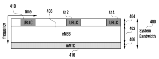
도 4는 이동 통신 시스템에서 고려되는 서비스인 eMBB, URLLC, mMTC용 데이터들이 주파수-시간 자원에서 할당된 모습의 다른 예를 나타낸다. 상기 이동 통신 시스템은 5G 혹은 NR 시스템을 의미할 수 있다. Figure 4 shows another example of how data for eMBB, URLLC, and mMTC, which are services considered in a mobile communication system, are allocated from frequency-time resources. The mobile communication system may mean a 5G or NR system.
도 4에서는 전체 시스템 주파수 대역(400)을 나누어 각 서브밴드(402, 404, 406) 각각이 서비스 및 데이터를 전송하는 용도로 사용될 수 있다. 상기 서브밴드는 미리 나누어져서 단말에게 상위 시그널링 될 수 있고, 혹은 기지국이 임의로 나누어 단말에게 서브밴드의 정보 없이 서비스들을 제공할 수도 있을 것이다. 도 4에서는 제1 서브밴드(402)는 eMBB 데이터 전송, 제2 서브밴드(404)는 URLLC 데이터 전송, 제3 서브밴드(406)에서는 mMTC 데이터 전송에 사용되고 있는 예제를 보여준다. 실시예에 따라, URLLC 전송에 사용되는 전송시간구간(transmission time interval, TTI)의 길이는 eMBB 혹은 mMTC 전송에 사용되는 TTI 길이보다 짧을 수 있다. In FIG. 4, the entire system frequency band (400) is divided so that each subband (402, 404, 406) can be used for transmitting services and data. The subbands can be divided in advance and signaled to the terminal, or the base station can arbitrarily divide them and provide services to the terminal without information on the subbands. FIG. 4 shows an example in which the first subband (402) is used for eMBB data transmission, the second subband (404) is used for URLLC data transmission, and the third subband (406) is used for mMTC data transmission. Depending on the embodiment, the length of the transmission time interval (TTI) used for URLLC transmission may be shorter than the length of the TTI used for eMBB or mMTC transmission.
도 5는 LTE/LTE-A에서의 트랜스포트 블록 및 코드 블록에 대한 CRC 추가를 도시하는 도면이다.Figure 5 is a diagram illustrating the addition of CRC to transport blocks and code blocks in LTE/LTE-A.
이하, 트랜스포트 블록(transport block) TB와 혼용될 수 있고, 코드 블록(code block)은 CB와 혼용될 수 있다. 또한, CRC 추가는 cyclic redundancy check(CRC) attachment를 의미한다. Hereinafter, the transport block (TB) can be used interchangeably with the code block (CB). Also, the addition of CRC means cyclic redundancy check (CRC) attachment.
LTE/LTE-A에서는 전송되는 spatial multiplexing layer의 수에 따라 아래의 표 2와 같은 TB size (TBS) 테이블(table)을 지원하며, 단말은 이를 기반으로 TBS index (ITBS) 및 할당된 PRB (physical resource block) 수에 (NPRB) 따른 TB size를 알 수 있다. 표 2는 spatial multiplexing layer가 1인 경우에 사용 가능한 TBS table 중 일부이며, spatial multiplexing layer가 2 이상인 경우 3GPP TS 36.213의 해당 TBS table을 참조할 수 있다.
LTE/LTE-A supports a TB size (TBS) table as shown in Table 2 below depending on the number of spatial multiplexing layers transmitted, and based on this, the terminal can know the TB size according to the TBS index (ITBS) and the number of allocated PRBs (physical resource blocks) (NPRB). Table 2 is part of the TBS table that can be used when the spatial multiplexing layer is 1, and if there are 2 or more spatial multiplexing layers, the corresponding TBS table of 3GPP TS 36.213 can be referenced.
[표 2]: Transport block size table (dimension 34×110) (길이 상 일부 부분은 생략됨)[Table 2]: Transport block size table (dimension 34×110) (some parts are omitted due to length)
또한, 아래의 표 3을 참조하면 단말은 DCI로 시그널링 되는 변조 및 코딩 방식(modulation and coding system, 이하 MCS) index (IMCS)를 통하여 ITBS를 통보 받게됨을 알 수 있다.
In addition, referring to Table 3 below, it can be seen that the terminal is notified of ITBS through the modulation and coding system (MCS) index (IMCS) signaled by DCI.
[표 3]: Modulation and TBS index table for PDSCH[Table 3]: Modulation and TBS index table for PDSCH
상기 설명한 바와 같이 기지국은 ITBS 및 NPRB에 따라 TBS를 결정하게 되며, 결정된 TB 및 아래의 수학식 1을 통하여 트랜스포트 블록에 대한 CRC를 생성하고 도 5의 503과 같이 TB 뒤에 추가한다.As described above, the base station determines the TBS according to the ITBS and NPRB, generates a CRC for the transport block using the determined TB and the
[수학식 1][Mathematical formula 1]
이후, 도 5의 505 단계에서 TB(501)와 TB CRC(503)는 N개의 코드 블록들(507, 509, 511, 513)로 나눠진다(codeblock segmentation). 여기서 N은 TB size와 maximum codeblock size (Z=6144), 그리고 CRC 길이(L=24)에 의하여 결정된다. 이후 각각의 코드 블록들과 아래의 수학식 2를 통하여 코드 블록에 대한 CRC가 생성되며 도 5의 517, 519, 521, 523과 같이 CB 뒤에 추가한다. Afterwards, in
[수학식 2][Mathematical formula 2]
이후, 기지국은 생성된 코드 블록(CB)과 CB CRC를 할당된 virtual RB (VRB)에 frequency first로 매핑(mapping)하여 전송한다. 단순한 예로 만약 할당된 VRB의 주파수 축 RE 개수가 하나의 CB 및 CB CRC에 의하여 생성되는 RE의 개수와 같다면 도 6의 604와 같이 resource mapping이 이루어지게 될 것이다. Thereafter, the base station transmits the generated code block (CB) and CB CRC by mapping them to the allocated virtual RB (VRB) in frequency first order. As a simple example, if the number of frequency-axis REs of the allocated VRB is equal to the number of REs generated by one CB and CB CRC, resource mapping will be performed as in 604 of Fig. 6.
도 6은 코드 블록 및 패리티 코드 블록에 CRC가 추가되는 과정을 설명하는 도면이다.Figure 6 is a diagram explaining the process of adding a CRC to a code block and a parity code block.
도 6에서 가로축은 시간, 세로축은 주파수 자원을 의미한다. 도 6은 개념도이며 CB 와 CRC의 위치 차이가 이들이 전송되는 실제 RE를 나타내기 위한 것은 아니다. 각 CB 및 CRC는 CB의 크기에 따라 하나 내지 다수의 OFDM 심볼에 걸쳐 전송될 수 있다. In Fig. 6, the horizontal axis represents time and the vertical axis represents frequency resources. Fig. 6 is a conceptual diagram, and the difference in the positions of CB and CRC is not intended to indicate the actual REs where they are transmitted. Each CB and CRC can be transmitted across one or more OFDM symbols depending on the size of the CB.
도 6을 참조하면, 606 및 610은 각각의 CB에 사용되는 종래의 채널코드(제 1 채널코드)와 별개로 CB 단위의 에러를 수정하기 위한 추가적인 채널코드(outer code, 제 2 채널코드)와 관련된다. 상기 제 2 채널코드가 적용되는 경우, 기지국은 데이터 영역(604)에서 같은 위치 혹은 미리 약속된 위치의 심볼들끼리 제 2 채널코드로 인코딩하여 패리티 심볼을 생성할 수 있다(602). 상기 생성된 패리티 심볼들은 패리티 블록(606)에 매핑되어 단말로 전송되며, 단말은 패리티 블록이 지원하는 한도 내의 데이터 영역 CB의 에러를 수정하는 것이 가능하다.Referring to FIG. 6, 606 and 610 relate to an additional channel code (outer code, second channel code) for correcting errors in CB units, separately from the conventional channel code (first channel code) used for each CB. When the second channel code is applied, the base station can generate parity symbols by encoding symbols at the same position or at predetermined positions in the data area (604) with the second channel code (602). The generated parity symbols are mapped to the parity block (606) and transmitted to the terminal, and the terminal can correct errors in the data area CB within the limit supported by the parity block.
이하에서 기술되는 eMBB 서비스를 제1 타입 서비스라 하며, eMBB용 데이터를 제1 타입 데이터라 한다. 상기 제1 타입 서비스 혹은 제1 타입 데이터는 eMBB에 국한되는 것은 아니고 고속 데이터 전송이 요구되거나 광대역 전송을 하는 경우에도 해당될 수 있다. 또한, URLLC 서비스를 제2 타입 서비스, URLLC용 데이터를 제2 타입 데이터라 한다. 상기 제2 타입 서비스 혹은 제2 타입 데이터는 URLLC에 국한되는 것은 아니고 저지연시간이 요구되거나 고신뢰도 전송이 필요한 경우에도 해당될 수 있다. 또한, mMTC 서비스를 제3 타입 서비스, mMTC용 데이터를 제3 타입 데이터라 한다. 상기 제3 타입 서비스 혹은 제3 타입 데이터는 mMTC에 국한되는 것은 아니고 저속도 혹은 넓은 커버리지, 혹은 저전력 등이 요구되는 경우에 해당될 수 있다. The eMBB service described below is referred to as a first type service, and data for eMBB is referred to as first type data. The first type service or the first type data is not limited to eMBB, and may be applied to cases where high-speed data transmission is required or wideband transmission is required. In addition, the URLLC service is referred to as a second type service, and data for URLLC is referred to as second type data. The second type service or the second type data is not limited to URLLC, and may be applied to cases where low latency is required or high-reliability transmission is required. In addition, the mMTC service is referred to as a third type service, and data for mMTC is referred to as third type data. The third type service or the third type data is not limited to mMTC, and may be applied to cases where low speed, wide coverage, or low power are required.
상기 3가지의 서비스 혹은 데이터를 전송하기 위해 각 타입별로 사용하는 물리계층 채널의 구조는 다를 수 있다. 예를 들어, 전송시간구간(TTI)의 길이, 주파수 자원의 할당 단위, 제어채널의 구조, 데이터의 매핑 방법 등이 다를 수 있다. The structure of the physical layer channel used for each type of transmission of the above three services or data may be different. For example, the length of the transmission time interval (TTI), the allocation unit of frequency resources, the structure of the control channel, and the data mapping method may be different.
본 발명에서는 상기 3가지의 서비스와 3가지의 데이터를 토대로 본 발명의 기술적 사상을 설명하지만 본 발명의 기술적 사상은 이에 제한되지 않고, 더 많은 종류의 서비스와 그에 해당하는 데이터에 적용될 수 있다. In the present invention, the technical idea of the present invention is explained based on the above three services and three data, but the technical idea of the present invention is not limited thereto and can be applied to more types of services and corresponding data.
본 발명에서는 제안하는 방법 및 장치를 설명하기 위해 종래의 LTE 혹은 LTE-A 시스템에서의 물리채널(physical channel)과 신호(signal)라는 용어가 사용될 수 있다. 하지만 본 발명의 내용은 LTE 및 LTE-A 시스템이 아닌 무선 통신 시스템에서 적용될 수 있는 것이다. In order to describe the proposed method and device in the present invention, the terms physical channel and signal in conventional LTE or LTE-A systems may be used. However, the contents of the present invention can be applied to wireless communication systems other than LTE and LTE-A systems.
본 발명은 상술한 바와 같이, 제1타입, 제2타입, 제3타입 서비스 혹은 데이터 전송을 위한 단말과 기지국의 송수신 동작을 정의하고, 서로 다른 타입의 서비스 혹은 데이터 스케줄링을 받는 단말들을 동일 시스템 내에서 함께 운영하기 위한 구체적인 방법을 제안한다. 본 발명에서 제1 타입 단말, 제2 타입 단말, 제3 타입 단말은 각각 제1 타입, 제2 타입, 제3 타입 서비스 혹은 데이터 스케줄링을 받은 단말을 가리킨다. As described above, the present invention defines transmission and reception operations of a terminal and a base station for transmitting a first type, a second type, or a third type service or data, and proposes a specific method for operating terminals receiving different types of service or data scheduling together within the same system. In the present invention, the first type terminal, the second type terminal, and the third type terminal refer to terminals receiving the first type, the second type, or the third type service or data scheduling, respectively.
이하 본 발명에서는 상향링크 스케줄링 승인 신호와 하향링크 데이터 신호를 제1 신호라 칭한다. 또한, 본 발명에서는 상향링크 스케줄링 승인에 대한 상향링크 데이터 신호와, 하향링크 데이터 신호에 대한 HARQ ACK/NACK을 제2 신호라 칭한다. Hereinafter, in the present invention, the uplink scheduling approval signal and the downlink data signal are referred to as the first signal. In addition, in the present invention, the uplink data signal for the uplink scheduling approval and the HARQ ACK/NACK for the downlink data signal are referred to as the second signal.
본 발명에서는 기지국이 단말에게 전송하는 신호 중에서, 단말로부터의 응답을 기대하는 신호이면 제1신호가 될 수 있으며, 제1신호에 해당하는 단말의 응답 신호가 제2신호로 될 수 있다. 또한, 본 발명에서 제1 신호의 서비스 종류는 eMBB, URLLC, mMTC 등의 카테고리에 속할 수 있다.In the present invention, among the signals transmitted by the base station to the terminal, a signal expecting a response from the terminal may be the first signal, and a response signal of the terminal corresponding to the first signal may be the second signal. In addition, the service type of the first signal in the present invention may belong to a category such as eMBB, URLLC, mMTC, etc.
이하 본 발명에서 제1 신호의 TTI 길이는, 제1 신호가 전송되는 시간의 길이를 의미한다. 또한, 본 발명에서 제2 신호의 TTI길이는, 제2 신호가 전송되는 시간의 길이를 의미한다. 또한, 본 발명에서 제2 신호 전송 타이밍이라함은 단말이 제2 신호를 언제 송신하고, 기지국이 제2 신호를 언제 수신하는지에 대한 정보이며, 이를 제2 신호 송수신 타이밍이라 언급할 수 있다.Hereinafter, in the present invention, the TTI length of the first signal means the length of time during which the first signal is transmitted. In addition, in the present invention, the TTI length of the second signal means the length of time during which the second signal is transmitted. In addition, in the present invention, the second signal transmission timing refers to information about when the terminal transmits the second signal and when the base station receives the second signal, and this may be referred to as the second signal transmission/reception timing.
이하, 본 발명에서 기지국이 제1 신호를 n번째 TTI에서 전송하였을 때 단말이 제2 신호를 n+k번째 TTI에서 전송한다고 가정하면, 상기 기지국이 단말에게 제2 신호를 전송할 타이밍을 알려준다는 것은 k값을 알려주는 것과 같다. Hereinafter, in the present invention, assuming that when the base station transmits the first signal in the nth TTI, the terminal transmits the second signal in the n+kth TTI, the base station informing the terminal of the timing to transmit the second signal is equivalent to informing the terminal of the k value.
또는, 기지국이 제1 신호를 n번째 TTI에서 전송하였을 때 단말이 제2 신호를 n+4+a번째 TTI에서 전송한다고 가정하면, 상기 기지국이 단말에게 제2 신호를 전송할 타이밍을 알려준다는 것은 오프셋 값 a를 알려주는 것과 같다. 상기 n+4+a 대신 n+3+a, n+5+a 등 다양한 방법으로 오프셋이 정의될 수 있으며, 이하 본 발명에서 언급되는 n+4+a 값도 마찬가지로 다양한 방법으로 오프셋 a 값이 정의될 수 있을 것이다.Alternatively, if it is assumed that when the base station transmits the first signal at the nth TTI, the terminal transmits the second signal at the n+4+ath TTI, the base station informing the terminal of the timing to transmit the second signal is equivalent to informing the terminal of the offset value a. Instead of n+4+a, the offset can be defined in various ways, such as n+3+a, n+5+a, etc., and the n+4+a value mentioned in the present invention below can also be defined in various ways as the offset a value.
본 발명에서의 내용은 FDD 및 TDD 시스템에서 적용이 가능한 것이다. The contents of the present invention can be applied to FDD and TDD systems.
이하 본 발명에서 상위 시그널링은 기지국에서 물리계층의 하향링크 데이터 채널을 이용하여 단말로, 혹은 단말에서 물리계층의 상향링크 데이터 채널을 이용하여 기지국으로 전달되는 신호 전달 방법이며, RRC 시그널링, 혹은 PDCP 시그널링, 혹은 MAC 제어요소(MAC control element; MAC CE)라고 언급될 수도 있다. In the present invention, the upper signaling is a signal transmission method in which a base station transmits a signal to a terminal using a downlink data channel of a physical layer, or a terminal transmits a signal to a base station using an uplink data channel of a physical layer, and may also be referred to as RRC signaling, PDCP signaling, or MAC control element (MAC CE).
도 7은 서로 다른 타입의 서비스 간 충돌 상황을 설명하기 위한 도면이다. Figure 7 is a diagram to explain a conflict situation between different types of services.
제2 타입 서비스는 10^-6 BLER 이하의 높은 신뢰도 및 1ms 이하의 낮은 지연시간을 요구한다. 따라서, 제1 타입 또는 제3 타입 서비스를 위한 주파수 시간 자원이 설정 혹은 스케쥴링되는 시점에서는 해당 주파수 시간 자원에서의 제2 타입 서비스의 전송 여부를 알 수 없는 경우가 있을 수 있다.
예를 들어, 제1 타입 또는 제3 타입 서비스의 TB가 도 7의 700과 같이 CB mapping되어 초기전송 되었다고 가정하자. 만약 도 7의 706이 지칭하는 시간 주파수 자원에서 제2 타입 서비스가 전송되어야 할 경우 기지국은 CB #4를 보내는 대신 제2 타입 서비스를 전송하게 될 것이다. 이로 인하여 제1 타입 또는 제3 타입 서비스를 수신하던 단말은 CB #4의 디코딩에 실패하게 될 것이며 NACK에 해당하는 제2신호를 기지국에 보고하게 될 것이다. For example, let's assume that TB of
기지국은 상기 제2 신호를 수신하게 되면 HARQ를 수행하기 위하여 초기전송 700에 대한 재전송 704를 수행하게 된다. 제1 타입 또는 제3 타입 서비스를 수신하던 단말은 704를 수신하면 제2 타입 서비스로 인하여 CRC 검사를 통과하지 못한 (decoding이 실패한) CB #4 (706)과 재전송된 CB#4 (708)을 컴바이닝(combining)하여 다시 디코딩을 시도하게 된다. When the base station receives the second signal, it performs a
이때 채널상황에 의하여 CRC 검사를 통과하지 못한 CB #7 (710)이 재전송된 CB #7와의 컴바이닝을 통하여 코딩 이득(coding gain)을 얻을 수 있는 것과는 달리, 706에는 상기 단말이 목적하는 데이터가 아닌 제2 타입 서비스의 데이터가 있으므로 컴바이닝을 수행하지 않는 것이 수신 성능 향상에 더 유리할 수 있다. At this time, unlike the case where CB #7 (710) that failed the CRC check due to channel conditions can obtain coding gain through combining with the retransmitted
그러나, 현재 NACK을 위한 제2 신호는 CB 단위가 아닌 TB 단위로 지원되므로 기지국은 단말이 보고한 NACK이 제2 타입 서비스와의 충돌 때문인지 아니면 채널 상황으로 인한 것인지를 알 수 없다. 또한, 단말은 CB 단위에서 CRC 체크를 수행하여 CB 별 디코딩 성공 여부를 알 수 있지만 제2 타입 서비스의 전송여부는 알 수 없기 때문에 어떤 CB의 디코딩 실패가 무엇 때문인지를 알 수 없다.However, since the second signal for current NACK is supported on a TB basis, not a CB basis, the base station cannot know whether the NACK reported by the terminal is due to a collision with the
도 8은 본 발명의 실시예에 따라 기지국의 데이터 재전송 시 긴급 통신과 관련된 서비스로 인해 NACK이 발생하는 경우를 설명하는 도면이다. FIG. 8 is a diagram explaining a case where a NACK occurs due to a service related to emergency communication when a base station retransmits data according to an embodiment of the present invention.
도 8에서는 초기전송 시에 채널상황으로 인하여 일부 CB 디코딩에 실패한 경우를 가정하였다. 이후 기지국이 HARQ를 위하여 첫 번째 재전송을 수행하였으나 이번에는 CB #4에서 제2 타입 서비스로 인한 디코딩 실패가 발생하고 기지국이 두 번째 재전송을 수행한 경우이다. 도 8과 같은 상황에서 단말은 각 CB 별 디코딩 성공 여부를 알 수 있으므로 CB #2의 경우 첫 번째 재전송에 대한 디코딩을 skip할 것이며, CB #7의 경우 combining을 통하여 디코딩에 성공하게 될 것이다. 한편 CB #4의 경우 최적의 코딩 이득을 얻기 위하여 채널로 인한 디코딩 실패가 발생한 초기전송과 두 번째 재전송 부분의 컴바이닝을 수행하되, 제2 타입 서비스와의 충돌로 디코딩 실패가 발생한 첫 번째 재전송 부분과의 컴바이닝은 수행하지 않아야 할 것이다. 그러나 이러한 동작은 상기 도 7에서 설명한 바와 같은 이유로 현재 지원이 되지 않는다.In Fig. 8, it is assumed that some CB decoding fails due to channel conditions during the initial transmission. Afterwards, the base station performs the first retransmission for HARQ, but this time, a decoding failure occurs in
상기 설명한 문제를 해결하기 위하여 본 발명에서는 다음과 같은 방법들을 고려하는 것이 가능하다. In order to solve the problem described above, the present invention can consider the following methods.
첫 번째 방법은 제2 타입 서비스와의 충돌이 발생 또는 예상되는 경우 가장 최근의 재전송만을 디코딩에 사용하는 것이다. 이는 초기전송 또는 그 이후의 재전송 중 하나가 제2 타입 서비스와 충돌한 것으로 간주하고 이들을 모두 버리는 것으로 이해할 수 있다. The first method is to use only the most recent retransmission for decoding when a collision with a
두 번째 방법은 제2 타입 서비스와의 충돌이 발생 또는 예상되는 해당 초기전송 또는 재전송들을 컴바이닝에서 제외시키는 방법이다. The second method is to exclude from combining those initial transmissions or retransmissions that are likely to conflict or are expected to conflict with a
세 번째 방법은 제2 타입 서비스와의 충돌이 발생 또는 예상되는 해당 초기전송 또는 재전송들에서 해당 CB들을 컴바이닝에서 제외시키는 방법이다The third method is to exclude those CBs from combining in those initial transmissions or retransmissions where a collision with a
이하 본 발명에서는 상기 방법들 중 하나 또는 다수의 조합을 수행하기 위한 구체적인 예제들을 설명하도록 한다. 이하 본 발명에서는 다수의 실시예를 통하여 상기 예제들을 설명하나 이는 독립적인 것들이 아니며 하나 이상의 실시예가 동시에 또는 복합적으로 적용되는 것이 가능하다.
Hereinafter, the present invention will describe specific examples for performing one or a combination of the above methods. The present invention will describe the above examples through a number of embodiments, but they are not independent, and one or more embodiments may be applied simultaneously or in combination.
<제1 실시예><Example 1>
제1 실시예는 도 9와 도 10을 참조하여 설명한다. 제1 실시예에서는 조건에 따른 NDI (new data indicator) 토글에 기반한 HARQ 관리를 통하여 문제점들을 해결한다. 기지국이 재전송이 필요한 TB의 NDI를 토글하기 위한 첫 번째 방법으로 만약 단말이 제2 타입 서비스와 함께 전송된 TB에서 NACK을 보고한 경우, 기지국은 해당 TB를 재전송하고 해당 NDI를 토글할 수 있다. The first embodiment is described with reference to FIGS. 9 and 10. In the first embodiment, the problems are solved through HARQ management based on conditional NDI (new data indicator) toggling. As a first method for a base station to toggle an NDI of a TB requiring retransmission, if a terminal reports a NACK in a TB transmitted with a second type service, the base station can retransmit the corresponding TB and toggle the corresponding NDI.
단말은 NACK의 원인이 제2 타입 서비스인지 아닌지를 알 수 없으나 기지국은 최소한 제2타입 서비스 전송 여부는 알 수 있으므로 조건에 따라 NDI를 토글하여 단말이 이를 초기전송으로 인식하게 할 수 있다. 상기 조건은 차후 상세히 구술한다. 즉, 단말은 이 경우 다시 전송된 데이터를 제2 타입 서비스로 인하여 디코딩 실패한 데이터와 컴바이닝하지 않게 될 것이다.The terminal cannot know whether the cause of the NACK is the
기지국이 재전송이 필요한 TB의 NDI를 토글하기 위한 두 번째 방법으로 만약 제2 타입 서비스의 TB와 제1 타입(또는 제3 타입) 서비스의 TB가 함께 전송된 경우, 기지국은 단말의 ACK/NACK 보고를 기다리지 않고 상기 조건에 따라 자동으로 해당 TB를 재전송하고 해당 NDI를 토글하는 것이 가능하다. 이 경우 오버헤드는 증가할 수 있으나 첫 번째 방법 대비 빠른 재전송을 수행하는 것이 가능하다. As a second method for the base station to toggle the NDI of the TB that requires retransmission, if the TB of the
앞서 설명한 바와 같이 할당된 VRB에서의 CB 별 자원 할당은 TBS table(MCS 및 NPRB의 함수)에 따라 결정되게 된다. As explained above, resource allocation per CB in the allocated VRB is determined according to the TBS table (a function of MCS and NPRB).
도 9는 본 발명의 실시예에 따른 변조 및 코딩 방식 인덱스 및 물리 자원 블록의 개수에 따른 코드 블록 매핑의 예시를 나타내는 도면이다.FIG. 9 is a diagram showing an example of code block mapping according to the number of modulation and coding scheme indices and physical resource blocks according to an embodiment of the present invention.
예컨대, 높은 변조 및 코딩 방식(modulation and coding scheme, 이하 MCS) 인덱스가 설정되거나 큰 물리 자원 블록(physical resource block, 이하 PRB)의 개수(NPRB)가 설정된 경우 도 9의 900과 같이 많은 수의 CB가 발생하게 되며 하나의 CB는 하나 내지는 작은 수의 OFDM 심볼에 분포하게 된다. For example, when a high modulation and coding scheme (hereinafter referred to as MCS) index is set or a large number of physical resource blocks (hereinafter referred to as PRBs) (NPRB) is set, a large number of CBs are generated, as in 900 of FIG. 9, and one CB is distributed over one or a small number of OFDM symbols.
따라서, 902의 주파수 시간 자원에서 제2 타입 서비스와 충돌하게 될 경우 하나의 CB에서 많은 부분이 상실될 확률이 높다. 이는 해당 CB의 디코딩이 실패할 확률이 높음을 의미하며, 만약 해당 CB 디코딩에 실패할 경우 단말은 TB 전체에 대한 NACK을 보고하게 될 것이다. Therefore, in case of a collision with a
반면, 낮은 MCS 인덱스가 설정되거나 작은 NPRB가 설정된 경우 도 9의 904과 같이 작은 수의 CB가 발생하게 되며 하나의 CB는 다수의 OFDM 심볼에 분포하게 된다. 따라서, 906의 주파수 시간 자원에서 제2 타입 서비스와 충돌하게 될 경우 하나의 CB에서 일부분만 상실될 확률이 높다. 이는 해당 CB의 디코딩이 성공할 확률이 높음을 의미한다. 따라서 기지국은 설정한 MCS 인덱스 및 NPRB를 기반으로 NDI 토글 여부를 결정할 수 있다.On the other hand, if a low MCS index is set or a small NPRB is set, a small number of CBs will occur as in 904 of Fig. 9, and one CB will be distributed over multiple OFDM symbols. Therefore, if there is a collision with the second type service in the frequency time resource of 906, there is a high probability that only a part of one CB will be lost. This means that the decoding of the corresponding CB has a high probability of success. Therefore, the base station can determine whether to toggle NDI based on the set MCS index and NPRB.
도 10은 본 발명의 제1 실시예에 따른 기지국의 HARQ 관리 방법을 나타내는 순서도이다. FIG. 10 is a flowchart showing a HARQ management method of a base station according to the first embodiment of the present invention.
도 10을 참조하면, 단말은 기지국으로부터 초기전송 또는 재전송을 수신하고 이를 디코딩하여 그 결과에 따라 ACK 또는 NACK을 기지국으로 보고한다(S1000). 만약, 상기 디코딩이 실패하는 경우 기지국은 단말로부터 NACK을 보고받게 되며 상기 NACK이 지칭하는 제1 타입 TB(또는 제3 타입 TB)과 제2 타입 전송이 충돌하였는지 여부를 판단한다(S1002).Referring to Fig. 10, the terminal receives an initial transmission or retransmission from the base station, decodes it, and reports ACK or NACK to the base station according to the result (S1000). If the decoding fails, the base station receives a NACK report from the terminal and determines whether the first type TB (or third type TB) indicated by the NACK and the second type transmission collide (S1002).
다만, 앞서 설명한 바와 같이 만약 기지국이 단말의 ACK/NACK 보고를 기다리지 않고 특정 조건에 따라 자동으로 해당 TB를 재전송하고 해당 NDI를 토글하여 재전송을 수행하는 경우 기지국은 단말의 ACK/NACK 보고를 기다리지 않을 수 있다. 이 경우 상기 S1000 단계는 생략될 수 있다.However, as explained above, if the base station automatically retransmits the corresponding TB and performs retransmission by toggling the corresponding NDI according to specific conditions without waiting for the ACK/NACK report of the terminal, the base station may not wait for the ACK/NACK report of the terminal. In this case, the S1000 step may be omitted.
제1 타입 TB(또는 제3 타입 TB)과 제2 타입 전송이 충돌하지 않은 경우, 기지국은 상기 제1 타입(또는 제3 타입) TB를 NDI 토글링 없이 재전송하여 단말이 해당 TB와 상기 재전송을 컴바이닝하도록 한다(S1006). If the
만약, 1002 단계에서 제1 타입 TB(또는 제3 타입 TB)과 제2 타입 전송이 충돌하였다고 판단된 경우, 기지국은 해당 제1 타입 또는 제3 타입 TB에 할당된 MCS 인덱스와 PRB의 개수를 기반으로 NDI 토글링 여부를 판단한다(S1004). If, at step 1002, it is determined that the
만약 MCS 인덱스와 PRB의 개수가 주어진 임계값(theshold)보다 클 경우 하나의 CB는 좁은 시간 영역에 분포하게 되므로 기지국은 단말에서 제2 타입 서비스와의 충돌로 인한 CB CRC fail이 발생한 것으로 추론하여 NDI를 토글 후 해당 TB를 재전송한다(S1008). If the MCS index and the number of PRBs are greater than a given threshold, one CB is distributed in a narrow time region, so the base station infers that a CB CRC fail has occurred due to a collision with a
실시예에 따라, 기지국은 상기 MCS 인덱스가 제1 임계값보다 크고 상기 PRB의 개수가 제2 임계값보다 크면, 상기 NDI를 토글한 후 상기 제1 데이터를 재전송하고, 상기 MCS 인덱스가 상기 제1 임계값보다 작고 상기 PRB의 개수가 상기 제2 임계값보다 작으면, 상기 NDI를 토글하지 않고 상기 제1 데이터를 재전송할 수 있다. In an embodiment, the base station may retransmit the first data after toggling the NDI if the MCS index is greater than a first threshold value and the number of PRBs is greater than a second threshold value, and may retransmit the first data without toggling the NDI if the MCS index is less than the first threshold value and the number of PRBs is less than the second threshold value.
다른 실시예에 따라, 상기 기지국은 상기 MCS 인덱스 및 상기 PRB의 개수를 이용하여 계산된 코드 블록(code block, 이하 CB)의 개수가 제3 임계값(예컨대, 2개) 보다 크면, 상기 NDI를 토글한 후 상기 제1 데이터를 재전송하하고, 상기 MCS 인덱스 및 상기 PRB의 개수를 이용하여 계산된 상기 CB의 개수가 제3 임계값보다 작으면, 상기 NDI를 토글하지 않고 상기 제1 데이터를 재전송할 수 있다. In another embodiment, if the number of code blocks (CBs) calculated using the MCS index and the number of PRBs is greater than a third threshold value (e.g., 2), the base station may retransmit the first data after toggling the NDI, and if the number of CBs calculated using the MCS index and the number of PRBs is less than the third threshold value, the base station may retransmit the first data without toggling the NDI.
이는 단말이 해당 TB를 초기전송으로 고려하여 제2 타입 서비스와 충돌하여 디코딩 실패 부분을 컴바이닝하지 않게 하기 위함이다. 상기 설명에 따르면 만약 MCS와 PRB가 주어진 임계값(theshold)보다 작을 경우 하나의 CB는 넓은 시간 영역에 분포하게 되므로 기지국은 단말에서 제2 타입 서비스와의 충돌로 인한 CB CRC check가 성공할 것으로 추론하여 NDI를 토글하지 않고 해당 TB를 재전송한다 (S1006). 이는 단말이 해당 TB를 재전송으로 고려하여 디코딩 실패한 부분을 컴바이닝하게 하기 위함이다. 이후, 1000단계에서 기지국이 단말로부터 ACK을 보고받게 되면 해당 TB에 대한 전송이 성공한 것으로 판단하고 단계를 종료한다.
This is to prevent the terminal from considering the corresponding TB as an initial transmission and combining the decoding failure portion due to collision with the
<제2 실시예><Example 2>
제2 실시예는 도 11을 참조하여 설명한다. 도 11은 본 발명의 제2 실시예에 따른 단말의 HARQ 관리 방법을 나타내는 순서도이다. The second embodiment is described with reference to Fig. 11. Fig. 11 is a flowchart showing a HARQ management method of a terminal according to the second embodiment of the present invention.
제2 실시예는 단말 구현 기반의 조건부 combining을 통한 HARQ 관리 방법을 설명한다. 단말은 제2 타입 서비스 전송에 대한 블라인드 디텍션(blind detection)을 수행하여 그 결과에 따라 기 수신된 초기전송 또는 재전송들과 그 이후에 수신된 재전송 간의 컴바이닝 여부를 결정할 수 있다. The second embodiment describes a HARQ management method through conditional combining based on terminal implementation. The terminal can perform blind detection for the second type service transmission and, based on the result, determine whether to combine the initial transmissions or retransmissions received previously and the retransmissions received thereafter.
단말은 임의의 주파수 대역에서, 데이터 통신과 관련된 제1 서비스에 상응하는 제1 데이터와 긴급 통신과 관련된 제2 서비스에 상응하는 제2 데이터가 단말에 동시에 스케줄링되면, 기지국으로부터 상기 제2 데이터를 수신할 수 있다. 상기 단말은 상기 제2 데이터에 대한 블라인드 검출(blind detection)을 수행하고, 상기 블라인드 검출 결과에 따라 상기 제2 데이터와 충돌하지 않는 적어도 하나의 코드 블록(code block)을 컴바이닝할 수 있다.A terminal may receive the second data from a base station when first data corresponding to a first service related to data communication and second data corresponding to a second service related to emergency communication are simultaneously scheduled for the terminal in an arbitrary frequency band. The terminal may perform blind detection on the second data and combine at least one code block that does not collide with the second data according to a result of the blind detection.
상기 제1 서비스는 eMBB (enhanced mobile broadband), 또는 mMTC (massive machine type communications)이고, 상기 제2 서비스는 URLLC (ultra-reliable and low-latency communications)일 수 있다.The first service may be eMBB (enhanced mobile broadband) or mMTC (massive machine type communications), and the second service may be URLLC (ultra-reliable and low-latency communications).
도 11을 참조하면, 단말은 수신한 TB에 대한 ACK/NACK를 결정하여 기지국으로 전송할 수 있다(S1100). 상기 단말은 CB에 대한 CRC 체크를 수행하고(S1102), URLLC에 대한 블라인드 검출 수행할 수 있다(S1104). 블라인드 검출 결과에 따라 URLLC가 검출되지 않으면, 상기 단말은 모든 NACK된 CB들을 컴바이닝할 수 있다(S1106). 블라인드 검출 결과에 따라 URLLC가 검출되면 상기 단말은 URLLC와 충돌하지 않는 NACK된 CB들을 컴바이닝할 수 있다(S1108).Referring to FIG. 11, the terminal can determine ACK/NACK for the received TB and transmit it to the base station (S1100). The terminal can perform a CRC check for the CB (S1102) and perform blind detection for URLLC (S1104). If URLLC is not detected according to the blind detection result, the terminal can combine all NACKed CBs (S1106). If URLLC is detected according to the blind detection result, the terminal can combine NACKed CBs that do not collide with URLLC (S1108).
단말은 제2 타입 서비스 전송 여부를 판단하기 위하여 제2 타입 서비스 전용 시퀀스나 기준신호 검출, 제2타입 서비스 전송이 의심되는 지역(NACK이 발생한 CB가 전송된 주파수-시간 자원)과 그렇지 않은 지역(CRC check를 통과한 CB가 전송된 주파수-시간 자원) 간 SNR(signal to Noise ratio) 비교 또는 LLR(log-likelihood ratio) 비교, 또는 상관도(correlation) 비교를 수행할 수 있다. In order to determine whether or not to transmit a
이후 제2 타입 서비스 전용 시퀀스나 기준신호가 해당 CB가 전송된 주파수-시간 자원에서 검출되거나, 상기 비교 값의 차이가 일정 기준보다 클 경우 단말은 해당 CB가 제2타입 서비스와의 충돌로 인하여 디코딩에 실패한 것으로 간주한다. 이후 단말은 제2타입 서비스와의 충돌로 인하여 decoding에 실패한 것으로 판단되는 CB에 대하여 combining을 수행하지 않음으로써 해당 TB가 decoding 성공할 확률을 높이고 불필요한 추가 재전송을 막을 수 있다. Thereafter, if a sequence or reference signal exclusive to the second type service is detected in the frequency-time resource transmitted by the CB, or if the difference between the above comparison values is greater than a certain standard, the terminal considers the CB to have failed in decoding due to a collision with the second type service. Thereafter, the terminal does not perform combining on the CB determined to have failed in decoding due to a collision with the second type service, thereby increasing the probability that the TB will succeed in decoding and preventing unnecessary additional retransmissions.
기지국은 이를 위하여 단말이 상기 비교를 쉽게 할 수 있도록 제2 타입 서비스의 전송확률이 높은 구간에서 해당 TB 전송에 같은 redundancy version을 적용할 수 있다. 기지국이 해당 TB의 A 번째 전송과 B 번째 전송에 같은 redundancy version을 적용할 경우 상기 두 전송의 N 번째 CB들 CB #A_N과 CB #B_B은 동일한 data를 포함하게 되므로 combining skip으로 인한 성능 열화 정도를 줄이고, 상기 비교를 용이하게 할 수 있는 장점이 있다.
To this end, the base station can apply the same redundancy version to the TB transmission in the section with a high transmission probability of the second type service so that the terminal can easily perform the comparison. If the base station applies the same redundancy version to the A-th and B-th transmissions of the TB, the N-th CBs CB #A_N and CB #B_B of the two transmissions will contain the same data, thereby reducing the degree of performance degradation due to combining skip and facilitating the comparison.
<제3 실시예><Example 3>
제3 실시예는 도 12 및 도 13을 참조하여 설명한다. 도 12는 본 발명의 제3실시예에 따른 단말의 HARQ 관리 방법을 설명하기 위한 도면이다. The third embodiment is described with reference to FIGS. 12 and 13. FIG. 12 is a drawing for explaining a HARQ management method of a terminal according to the third embodiment of the present invention.
제3 실시예에서는 1 bit 지시자(indication)를 통한 제2 타입 서비스 전송 영역에서의 HARQ flushing/skipping 통하여 상기 문제점들을 해결한다. 본 실시예에서 제2 타입 서비스 전송이 가능한 주파수 시간 자원 영역(1202)이 단말들에게 L1 signaling 또는 higher layer (RRC) signaling 될 수 있는 환경을 가정한다. In the third embodiment, the above problems are solved through HARQ flushing/skipping in the
제1 타입 또는 제3 타입 서비스 전송을 위한 주파수 시간 자원 영역(1200)이 URLLC 영역(1202)보다 크다고 할 때, 제2 타입 서비스와의 충돌(1204)이 일부 주파수 및 시간 자원에서 발생할 수 있을 것이다. 이 경우, 기지국은 해당 초기전송 또는 재전송에 대한 재전송을 수행하면서 1206 및 1208에 대한 제어 영역에 제2 타입 서비스와의 충돌(1204) 발생 여부(또는 제2 타입 서비스의 전송 여부)에 대한 1-bit L1 시그널링(signaling) 또는 1-bit RRC 시그널링(signaling)을 제공할 수 있다. When the frequency time resource area (1200) for the transmission of the first type or third type service is larger than the URLLC area (1202), a collision (1204) with the second type service may occur in some frequency and time resources. In this case, the base station may provide 1-bit L1 signaling or 1-bit RRC signaling for whether a collision (1204) with the second type service occurs (or whether the second type service is transmitted) to the control area for 1206 and 1208 while performing retransmission for the initial transmission or retransmission.
예를 들어, 상기 1-bit L1 signaling 또는 1bit RRC signaling이 '1'일 경우 해당 시그널링과 연결된 TB가 전송된 자원에서 제2 타입 서비스가 전송되었음을 의미할 수 있다. 반대로, 상기 1-bit L1 signaling 또는 1-bit RRC signaling이 '0'일 경우 상기 자원에서 제2 타입 서비스가 전송되지 않았음을 의미할 수 있다. For example, if the 1-bit L1 signaling or 1-bit RRC signaling is '1', it may mean that a
단말을 이를 통하여 제2 타입 서비스 전송 가능지역(1202)의 CB들(1206)과, 제2 타입 서비스 전송 가능지역(1202)에 속하지 않는 주파수 시간 자원에서 전송된 CB들(1208)에 대한 컴바이닝(combining) 여부를 결정할 수 있다. Through this, the terminal can determine whether to combine CBs (1206) in the second type service transmission possible area (1202) and CBs (1208) transmitted in frequency time resources that do not belong to the second type service transmission possible area (1202).
예를 들어, 단말이 기지국으로부터 상기 1-bit L1 signaling 또는 1-bit RRC signaling을 수신하여 재전송된 1206의 이전 전송이 제2 타입 서비스 전송과 겹친 경우 1206에 속하는 CB들에 대한 컴바이닝을 수행하지 않을 수 있다. 또한, 단말은 1208에 속하는 CB들에 대한 combining은 수행하도록 하는 것이 가능하다. 또 다른 예시로 단말이 기지국으로부터 상기 1-bit L1 signaling 또는 1-bit RRC signaling을 수신하여 재전송된 1206의 이전 전송이 제2 타입 서비스 전송과 겹친 경우 1206 및 1208에 속하는 모든 CB들에 대한 combining을 수행하지 않도록 약속하는 것도 가능하다.For example, if the terminal receives the 1-bit L1 signaling or 1-bit RRC signaling from the base station and the previous transmission of 1206, which was retransmitted, overlaps with the second type service transmission, the terminal may not perform combining for CBs belonging to 1206. Additionally, it is possible for the terminal to perform combining for CBs belonging to 1208. As another example, it is also possible to promise not to perform combining for all CBs belonging to 1206 and 1208 if the previous transmission of 1206, which was retransmitted, overlaps with the second type service transmission when the terminal receives the 1-bit L1 signaling or 1-bit RRC signaling from the base station.
도 13은 본 발명의 제3 실시예에 따른 단말의 HARQ 관리 방법을 나타내는 순서도이다. 도 13을 참조하면, 단말은 기지국으로부터 수신한 TB에 대한 ACK/NACK를 결정하고, 상기 ACK/NACK를 상기 기지국으로 전송할 수 있다(S1300).Fig. 13 is a flowchart showing a HARQ management method of a terminal according to the third embodiment of the present invention. Referring to Fig. 13, a terminal can determine ACK/NACK for a TB received from a base station and transmit the ACK/NACK to the base station (S1300).
상기 TB가 재전송을 위한 것이면, 상기 단말은 상기 기지국으로부터 전송되는 컴바이닝을 위한 1-bit 지시자를 리드할 수 있다(S1302). 상기 1-bit 지시자에 따라 URLLC가 없음을 확인하면 상기 단말은 모든 NACK된 CB들을 컴바이닝할 수 있다(S1304). 상기 1-bit 지시자에 따라 URLLC가 전송되었음을 확인하면 상기 단말은 URLLC 영역에 존재하지 않는 NACK된 CB들을 컴바이닝할 수 있다(S1306).
If the above TB is for retransmission, the terminal can read a 1-bit indicator for combining transmitted from the base station (S1302). If it is confirmed that there is no URLLC according to the 1-bit indicator, the terminal can combine all NACKed CBs (S1304). If it is confirmed that URLLC has been transmitted according to the 1-bit indicator, the terminal can combine NACKed CBs that do not exist in the URLLC area (S1306).
<제4 실시예><Example 4>
제4 실시예는 도 14 및 도 15를 참조하여 설명한다. 도 14는 본 발명의 제4 실시예에 따른 HARQ 관리 방법을 설명하기 위한 도면이다. The fourth embodiment is described with reference to FIGS. 14 and 15. FIG. 14 is a drawing for explaining a HARQ management method according to the fourth embodiment of the present invention.
제4 실시예에서는 복수의 비트들(multiple bits) 지시자(indication)를 통한 CB 또는 CB 서브그룹(subgroup) 별 HARQ flushing/skipping 시그널링을 통하여 문제점들을 해결한다. In the fourth embodiment, the problems are solved through HARQ flushing/skipping signaling per CB or CB subgroup through indication of multiple bits.
제4 실시예에서는 제2 타입 서비스 전송이 가능한 주파수 시간 자원 영역에 대한 설정 정보와는 별도로 기지국이 단말에게 다수의 비트로 구성된 L1 시그널링을 통하여 각 CB 별 또는 CB 서브그룹 별 컴바이닝 여부를 알려주는 것이 가능하다. In the fourth embodiment, separately from the configuration information for the frequency time resource area in which the second type service transmission is possible, it is possible for the base station to inform the terminal of whether combining is performed for each CB or CB subgroup through L1 signaling consisting of a number of bits.
도 14는 3비트의 L1 시그널링을 사용하는 경우의 예시를 도시하는 도면이다. 이 경우 첫 번째 비트는 첫 번째 CB 서브그룹의 컴바이닝 여부를, 두 번째 비트는 두 번째 CB 서브그룹의 컴바이닝 여부를, 세 번째 비트는 세 번째 CB 서브그룹의 컴바이닝 여부를 시그널링하도록 약속될 수 있다. 이는 쉽게 다른 수의 비트맵을 사용하는 경우로 변경이 가능하다. 어떤 전송 시점에서의 TB가 다수의 CB로 구성될 경우 각 CB들은 일정 규칙에 따라 CB 서브그룹 중 하나에 매핑된다. Fig. 14 is a diagram illustrating an example of a case where 3-bit L1 signaling is used. In this case, the first bit can be agreed to signal whether the first CB subgroup is combined, the second bit to signal whether the second CB subgroup is combined, and the third bit to signal whether the third CB subgroup is combined. This can be easily changed to a case where a different number of bitmaps is used. When a TB at a certain transmission point is composed of multiple CBs, each CB is mapped to one of the CB subgroups according to a certain rule.
일례로 해당 전송 시점에서의 TB가 총 N개의 CB로 분할(segmentation)된다면 상기 M개의 비트로 구성되는 비트맵의 각 비트들은 처음 (M-1)개의 비트는 각각 [N/M] 개의 CB들에 대한 컴바이닝 여부를 지시하며, 마지막 M 번째 비트는 N-(M-1)[N/M] 개의 CB들에 대한 컴바이닝 여부를 지시하도록 약속되는 것이 가능하다. 만약 도 12와 같이 해당 전송 시점에서의 TB가 총 6개의 CB로 나누어지고 총 3개의 L1 signaling이 지원되는 경우 첫 번째 비트(1200)는 처음 두 개의 CB들 1210과 1212을 이전 전송들과 컴바이닝 수행할지 여부를 알려주며, 두 번째 비트(1202)는 그 다음 두 개의 CB들 1214과 1216을 이전 전송들과 컴바이닝 수행할지 여부를 알려주며, 세 번째 비트(1204)는 마지막 두 개의 CB들 1218과 1220을 이전 전송들과 컴바이닝 수행할지 여부를 알려준다. For example, if the TB at the transmission point in time is segmented into a total of N CBs, it is possible to promise that each bit of the bitmap consisting of the M bits will indicate whether to combine the first (M-1) bits for each of [N/M] CBs, and the last M-th bit will indicate whether to combine N-(M-1)[N/M] CBs. If the TB at the transmission point in time is divided into a total of 6 CBs as in Fig. 12 and a total of 3 L1 signalings are supported, the first bit (1200) indicates whether the first two CBs 1210 and 1212 are combined with previous transmissions, the second bit (1202) indicates whether the next two CBs 1214 and 1216 are combined with previous transmissions, and the third bit (1204) indicates whether the last two CBs 1218 and 1220 are combined with previous transmissions.
제3 실시예 및 제4 실시예에서 제2 타입 서비스와의 충돌을 시그널링하기 위한 1-비트 시그널링 또는 비트맵 시그널링은 임의의 TB의 재전송 시에는 앞서 설명한 것과 같은 의미를 가질 수 있으나, TB의 초기전송 시에는 다른 의미를 가질 수 있다. 이는 상기 시그널링을 위하여 기존의 L1 signaling 중 일부가 재사용될 수 있음을 의미한다. 예를 들어 재전송 상황에서 한 개의 트랜스포트 블록 만을 전송하는 경우 DCI(downlink control information)에는 첫 번째 transport block을 위한 정보(MCS, NDI, redundancy version 등)만이 포함된다. 이때 두 번째 transport block을 위한 페이로드(payload)는 상기 시그널링을 위하여 재사용되는 것이 가능하다.In the third and fourth embodiments, the 1-bit signaling or bitmap signaling for signaling a collision with the
도 15는 본 발명의 제4 실시예에 따른 단말의 HARQ 관리 방법을 나타내는 순서도이다. Figure 15 is a flowchart showing a HARQ management method of a terminal according to the fourth embodiment of the present invention.
도 15를 참조하면, 단말은 기지국으로부터 전송되는 TB에 대한 ACK/NACK를 결정하고, 상기 ACK/NACK를 상기 기지국으로 전송할 수 있다(S1500).Referring to FIG. 15, the terminal can determine ACK/NACK for TB transmitted from a base station and transmit the ACK/NACK to the base station (S1500).
상기 TB가 재전송을 위한 것이면, 상기 단말은 상기 기지국으로부터 전송되는 컴바이닝을 위한 M-bit 지시자를 리드할 수 있다(S1502). 상기 단말은 상기 M-bit 지시자에 따라 URLLC 영역에 존재하지 않는 NACK된 CB들을 컴바이닝할 수 있다(S1504). If the above TB is for retransmission, the terminal can read the M-bit indicator for combining transmitted from the base station (S1502). The terminal can combine NACKed CBs that do not exist in the URLLC area according to the M-bit indicator (S1504).
본 발명의 상기 실시예들을 수행하기 위해 단말과 기지국의 송신부, 수신부, 처리부가 각각 도 16과 도 17에 도시되어 있다. 본 발명의 제1 실시예부터 제4 실시예까지는 다른 서비스와 제2 타입 서비스 간 충돌 여부를 결정하고 이에 기반하여 제2 신호를 처리하는 동작을 수행하는 기지국과 단말의 송수신 방법이 나타나 있으며, 이를 수행하기 위해 기지국과 단말의 수신부, 처리부, 송신부가 각각 실시 예들에 따라 동작하여야 한다. In order to perform the above embodiments of the present invention, a transmitter, a receiver, and a processor of a terminal and a base station are respectively illustrated in FIGS. 16 and 17. From the first to fourth embodiments of the present invention, a transmission/reception method of a base station and a terminal is shown for determining whether there is a collision between another service and a second type service and performing an operation of processing a second signal based on the determination, and in order to perform this, the receiver, the processor, and the transmitter of the base station and the terminal must each operate according to the embodiments.
도 16은 본 발명의 실시예에 따른 단말의 내부 구조를 도시하는 블록도이다. 도 16에서 도시되는 바와 같이, 본 발명의 단말은 단말기 수신부(1600), 단말기 송신부(1604), 단말기 처리부(1602)를 포함할 수 있다. Fig. 16 is a block diagram showing the internal structure of a terminal according to an embodiment of the present invention. As shown in Fig. 16, the terminal of the present invention may include a terminal receiving unit (1600), a terminal transmitting unit (1604), and a terminal processing unit (1602).
단말기 수신부(1600)와 단말기 송신부(1604)를 통칭하여 본 발명의 실시 예에서는 송수신부라 칭할 수 있다. 송수신부는 기지국과 신호를 송수신할 수 있다. 상기 신호는 제어 정보와, 데이터를 포함할 수 있다. 이를 위해, 송수신부는 송신되는 신호의 주파수를 상승 변환 및 증폭하는 RF 송신기와, 수신되는 신호를 저 잡음 증폭하고 주파수를 하강 변환하는 RF 수신기 등으로 구성될 수 있다. The terminal receiving unit (1600) and the terminal transmitting unit (1604) may be collectively referred to as a transceiver in the embodiment of the present invention. The transceiver unit may transmit and receive signals with a base station. The signals may include control information and data. To this end, the transceiver unit may be composed of an RF transmitter that up-converts and amplifies the frequency of a transmitted signal, and an RF receiver that low-noise amplifies and down-converts the frequency of a received signal.
또한, 송수신부는 무선 채널을 통해 신호를 수신하여 단말기 처리부(1602)로 출력하고, 단말기 처리부(1602)로부터 출력된 신호를 무선 채널을 통해 전송할 수 있다. 단말기 처리부(1602)는 상술한 본 발명의 실시예들에 따라 단말이 동작할 수 있도록 일련의 과정을 제어할 수 있다. 예를 들어, 단말기 수신부(1600)에서 기지국으로부터 제2신호 전송 타이밍 정보를 포함하는 신호를 수신하고, 단말기 처리부(1602)는 제2신호 전송 타이밍을 해석하도록 제어할 수 있다. 이후, 단말기 송신부(1604)에서 상기 타이밍에서 제2 신호를 송신할 수 있다.In addition, the transceiver may receive a signal through a wireless channel and output it to the terminal processing unit (1602), and transmit the signal output from the terminal processing unit (1602) through the wireless channel. The terminal processing unit (1602) may control a series of processes so that the terminal may operate according to the embodiments of the present invention described above. For example, the terminal receiving unit (1600) may receive a signal including second signal transmission timing information from a base station, and the terminal processing unit (1602) may control the interpretation of the second signal transmission timing. Thereafter, the terminal transmitting unit (1604) may transmit the second signal at the timing.
도 17은 본 발명의 실시예에 따른 기지국의 내부 구조를 도시하는 블록도이다. 도 17에서 도시되는 바와 같이, 본 발명의 기지국은 기지국 수신부(1701), 기지국 송신부(1705), 기지국 처리부(1703)를 포함할 수 있다. Fig. 17 is a block diagram showing the internal structure of a base station according to an embodiment of the present invention. As shown in Fig. 17, the base station of the present invention may include a base station receiving unit (1701), a base station transmitting unit (1705), and a base station processing unit (1703).
기지국 수신부(1701)와 기지국 송신부(1705)를 통칭하여 본 발명의 실시 예에서는 송수신부라 칭할 수 있다. 송수신부는 단말과 신호를 송수신할 수 있다. 상기 신호는 제어 정보와, 데이터를 포함할 수 있다. 이를 위해, 송수신부는 송신되는 신호의 주파수를 상승 변환 및 증폭하는 RF 송신기와, 수신되는 신호를 저 잡음 증폭하고 주파수를 하강 변환하는 RF 수신기 등으로 구성될 수 있다. The base station receiving unit (1701) and the base station transmitting unit (1705) may be collectively referred to as a transceiver in the embodiment of the present invention. The transceiver unit may transmit and receive signals with a terminal. The signals may include control information and data. To this end, the transceiver unit may be composed of an RF transmitter that up-converts and amplifies the frequency of a transmitted signal, and an RF receiver that low-noise amplifies and down-converts the frequency of a received signal.
또한, 송수신부는 무선 채널을 통해 신호를 수신하여 기지국 처리부(1703)로 출력하고, 단말기 처리부(1703)로부터 출력된 신호를 무선 채널을 통해 전송할 수 있다. 기지국 처리부(1703)는 상술한 본 발명의 실시예에 따라 기지국이 동작할 수 있도록 일련의 과정을 제어할 수 있다. 예를 들어, 기지국 처리부(1703)는 제2 신호 처리방법을 결정하고, 단말에게 전달할 상기 제2 신호 정보를 생성하도록 제어할 수 있다. 이후, 기지국 송신부(1705)에서 상기 제2 신호 정보를 단말에게 전달하고, 기지국 수신부(1701)는 상기 제2 신호에 따라 초기전송 및 재전송의 컴바이닝을 수행한다. In addition, the transceiver can receive a signal through a wireless channel and output it to the base station processing unit (1703), and transmit the signal output from the terminal processing unit (1703) through the wireless channel. The base station processing unit (1703) can control a series of processes so that the base station can operate according to the above-described embodiment of the present invention. For example, the base station processing unit (1703) can determine a second signal processing method and control to generate the second signal information to be transmitted to the terminal. Thereafter, the base station transmitting unit (1705) transmits the second signal information to the terminal, and the base station receiving unit (1701) performs combining of initial transmission and retransmission according to the second signal.
또한, 본 발명의 일 실시예에 따르면, 기지국 처리부(1703)는 상기 제2 신호 처리 정보를 포함하는 하향링크 제어 정보(Downlink Control Information, DCI)를 생성하도록 제어할 수 있다.In addition, according to one embodiment of the present invention, the base station processing unit (1703) can be controlled to generate downlink control information (DCI) including the second signal processing information.
한편, 본 명세서와 도면에 개시된 본 발명의 실시예들은 본 발명의 기술 내용을 쉽게 설명하고 본 발명의 이해를 돕기 위해 특정 예를 제시한 것일 뿐이며, 본 발명의 범위를 한정하고자 하는 것은 아니다. 즉 본 발명의 기술적 사상에 바탕을 둔 다른 변형예들이 실시 가능하다는 것은 본 발명의 속하는 기술 분야에서 통상의 지식을 가진 자에게 자명한 것이다. 또한 상기 각각의 실시 예는 필요에 따라 서로 조합되어 운용할 수 있다. 예컨대, 본 발명의 실시예1와 실시예2의 일부분들 또는 실시예3과 실시예4의 일부분들이 서로 조합되어 기지국과 단말이 운용될 수 있다. 또한 상기 실시예들은 FDD LTE 시스템을 기준으로 제시되었지만, TDD LTE 시스템, 5G 혹은 NR 시스템 등 다른 시스템에도 상기 실시예의 기술적 사상에 바탕을 둔 다른 변형예들이 실시 가능할 것이다. Meanwhile, the embodiments of the present invention disclosed in this specification and the drawings are only intended to easily explain the technical contents of the present invention and to provide specific examples to help understand the present invention, and are not intended to limit the scope of the present invention. That is, it will be apparent to a person having ordinary skill in the art that other modified examples based on the technical idea of the present invention are possible. In addition, each of the above embodiments may be combined and operated as needed. For example, parts of
상기에 기술한 바와 같이 본 발명에서는 상향링크 스케줄링 승인 신호와 하향링크 데이터 신호를 제1신호라 칭하였고, 상향링크 스케줄링 승인에 대한 상향링크 데이터 신호와, 하향링크 데이터 신호에 대한 HARQ ACK/NACK을 제2신호라 칭하였다. 하지만 상기와 같은 제1신호 및 제2신호의 종류는 본 발명의 기술 내용을 쉽게 설명하고 본 발명의 이해를 돕기 위해 특정 예를 제시한 것일 뿐이며, 본 발명의 범위를 한정하고자 하는 것은 아니다. 즉 본 발명의 기술적 사상에 바탕을 둔 다른 제1신호 및 제2신호에도 실시 가능하다는 것은 본 발명의 속하는 기술 분야에서 통상의 지식을 가진 자에게 자명한 것이다.As described above, in the present invention, the uplink scheduling grant signal and the downlink data signal are referred to as first signals, and the uplink data signal for the uplink scheduling grant and the HARQ ACK/NACK for the downlink data signal are referred to as second signals. However, the types of the first signal and the second signal as described above are only specific examples presented to easily explain the technical content of the present invention and help in the understanding of the present invention, and are not intended to limit the scope of the present invention. That is, it is obvious to a person having ordinary skill in the art to which the present invention pertains that the present invention can be implemented also to other first signals and second signals based on the technical idea of the present invention.
301, 408: eMBB
303, 305, 307, 410, 412, 414: URLLC
309, 416: mMTC
501: 트랜스포트 블록(TB)
503: TB에 대한 CRC
507, 509, 511, 513: 코드 블록(CB)
517, 519, 521, 523: CB에 대한 CRC
1600: 단말기 수신부
1602: 단말기 처리부
1604: 단말기 송신부
1701: 기지국 수신부
1703: 기지국 처리부
1705: 기지국 송신부301, 408: eMBB
303, 305, 307, 410, 412, 414: URLLC
309, 416: mMTC
501: Transport Block (TB)
503: CRC for TB
507, 509, 511, 513: Code Block (CB)
517, 519, 521, 523: CRC for CB
1600: Terminal receiver
1602: Terminal Processing Unit
1604: Terminal Transmitter
1701: Base station receiver
1703: Base station processing unit
1705: Base station transmitter
Claims (46)
기지국으로부터 하나 이상의 코드 블록 그룹(code block group)을 포함하는 제1 데이터를 수신하는 단계로, 상기 제1 데이터는 복수의 코드 블록으로 구성되고, 각 코드 블록 그룹은 하나 이상의 코드 블록을 포함하고;
상기 제1 데이터에 대한 NACK(negative acknowledge)를 상기 기지국으로 전송하는 단계;
상기 기지국으로부터 상기 제1 데이터의 재전송 데이터를 스케줄링하는 하향링크 제어 정보를 수신하는 단계로, 상기 하향링크 제어 정보는 상기 단말의 코드 블록 그룹 단위의 HARQ (hybrid automatic repeat request) 컴바이닝 여부를 지시하는 지시자를 포함하고; 및
상기 지시자가 HARQ 컴바이닝을 지시할 경우 상기 재전송 데이터 내의 적어도 하나의 코드 블록 그룹과 상기 제1 데이터 내의 같은 코드 블록 그룹의 HARQ 컴바이닝을 수행하는 단계를 포함하는 것을 특징으로 하는 방법.In a method performed by a terminal in a mobile communication system,
A step of receiving first data including one or more code block groups from a base station, wherein the first data is composed of a plurality of code blocks, and each code block group includes one or more code blocks;
A step of transmitting a NACK (negative acknowledgement) for the first data to the base station;
A step of receiving downlink control information for scheduling retransmission data of the first data from the base station, wherein the downlink control information includes an indicator indicating whether to perform hybrid automatic repeat request (HARQ) combining of code block groups of the terminal; and
A method characterized by comprising a step of performing HARQ combining of at least one code block group in the retransmission data and the same code block group in the first data when the above instruction indicates HARQ combining.
상기 지시자가 HARQ 플러싱 (flushing)을 지시할 경우, 상기 제1 데이터의 적어도 하나의 코드 블록 그룹의 플러싱 및 상기 재전송 데이터의 디코딩을 수행하는 단계를 더 포함하는 것을 특징으로 하는 방법.In Article 21,
A method characterized in that, if the above instruction indicates HARQ flushing, the method further comprises the step of performing flushing of at least one code block group of the first data and decoding of the retransmitted data.
상기 적어도 하나의 코드 블록 그룹은 상기 제1 데이터의 전송과 제2 데이터의 전송이 충돌하는 자원 상의 코드 블록 그룹인 것을 특징으로 하는 방법.In Article 21,
A method characterized in that said at least one code block group is a code block group on a resource where transmission of said first data and transmission of said second data conflict.
상기 제1 데이터는 eMBB (enhanced mobile broadband), 또는 mMTC (massive machine type communications) 서비스를 위한 데이터이고,
상기 제2 데이터는 URLLC (ultra-reliable and low-latency communications) 서비스를 위한 데이터인 것을 특징으로 하는 방법.In Article 23,
The above first data is data for eMBB (enhanced mobile broadband) or mMTC (massive machine type communications) service,
A method characterized in that the second data is data for URLLC (ultra-reliable and low-latency communications) service.
단말로 하나 이상의 코드 블록 그룹(code block group)을 포함하는 제1 데이터를 전송하는 단계로, 상기 제1 데이터는 복수의 코드 블록으로 구성되고, 각 코드 블록 그룹은 하나 이상의 코드 블록을 포함하고;
상기 단말로부터 상기 제1 데이터에 대한 NACK(negative acknowledge)를 수신하는 단계;
상기 단말로 상기 제1 데이터의 재전송 데이터를 스케줄링하는 하향링크 제어 정보를 전송하는 단계로, 상기 하향링크 제어 정보는 상기 단말의 코드 블록 그룹 단위의 HARQ (hybrid automatic repeat request) 컴바이닝 여부를 지시하는 지시자를 포함하고,
상기 지시자는 HARQ 컴바이닝을 지시하여 상기 재전송 데이터 내의 적어도 하나의 코드 블록 그룹과 상기 제1 데이터 내의 같은 코드 블록 그룹의 HARQ 컴바이닝이 수행되도록 지시하는 것을 특징으로 하는 방법.In a method performed by a base station in a mobile communication system,
A step of transmitting first data including one or more code block groups to a terminal, wherein the first data is composed of a plurality of code blocks, and each code block group includes one or more code blocks;
A step of receiving a NACK (negative acknowledgement) for the first data from the terminal;
A step of transmitting downlink control information for scheduling retransmission data of the first data to the terminal, wherein the downlink control information includes an indicator indicating whether to perform hybrid automatic repeat request (HARQ) combining of code block groups of the terminal,
A method characterized in that the above instruction instructs HARQ combining to perform HARQ combining of at least one code block group in the retransmission data and the same code block group in the first data.
상기 지시자는 HARQ 플러싱 (flushing)을 지시하여 상기 제1 데이터의 적어도 하나의 코드 블록 그룹의 플러싱 및 상기 재전송 데이터의 디코딩이 수행되도록 지시하는 것을 특징으로 하는 방법.In Article 26,
A method characterized in that the above instruction instructs HARQ flushing to cause flushing of at least one code block group of the first data and decoding of the retransmitted data to be performed.
상기 적어도 하나의 코드 블록 그룹은 상기 제1 데이터의 전송과 제2 데이터의 전송이 충돌하는 자원 상의 코드 블록 그룹인 것을 특징으로 하는 방법.In Article 26,
A method characterized in that said at least one code block group is a code block group on a resource where transmission of said first data and transmission of said second data conflict.
상기 제1 데이터는 eMBB (enhanced mobile broadband), 또는 mMTC (massive machine type communications) 서비스를 위한 데이터이고,
상기 제2 데이터는 URLLC (ultra-reliable and low-latency communications) 서비스를 위한 데이터인 것을 특징으로 하는 방법.In Article 28,
The above first data is data for eMBB (enhanced mobile broadband) or mMTC (massive machine type communications) service,
A method characterized in that the second data is data for URLLC (ultra-reliable and low-latency communications) service.
신호를 송수신하는 송수신부; 및
기지국으로부터 하나 이상의 코드 블록 그룹(code block group)을 포함하는 제1 데이터를 수신하고, 상기 제1 데이터는 복수의 코드 블록으로 구성되고, 각 코드 블록 그룹은 하나 이상의 코드 블록을 포함하고, 상기 제1 데이터에 대한 NACK(negative acknowledge)를 상기 기지국으로 전송하고, 상기 기지국으로부터 상기 제1 데이터의 재전송 데이터를 스케줄링하는 하향링크 제어 정보를 수신하고, 상기 하향링크 제어 정보는 상기 단말의 코드 블록 그룹 단위의 HARQ (hybrid automatic repeat request) 컴바이닝 여부를 지시하는 지시자를 포함하고, 및 상기 지시자가 HARQ 컴바이닝을 지시할 경우 상기 재전송 데이터 내의 적어도 하나의 코드 블록 그룹과 상기 제1 데이터 내의 같은 코드 블록 그룹의 HARQ 컴바이닝을 수행하도록 제어하는 제어부를 포함하는 것을 특징으로 하는 단말. In a terminal of a mobile communication system,
A transceiver for transmitting and receiving signals; and
A terminal characterized in that the terminal receives first data including one or more code block groups from a base station, the first data is composed of a plurality of code blocks, each code block group includes one or more code blocks, transmits a negative acknowledge (NACK) for the first data to the base station, and receives downlink control information for scheduling retransmission data of the first data from the base station, the downlink control information includes an indicator indicating whether to perform hybrid automatic repeat request (HARQ) combining of code block groups of the terminal, and includes a control unit for controlling to perform HARQ combining of at least one code block group in the retransmission data and the same code block group in the first data when the indicator indicates HARQ combining.
신호를 송수신하는 송수신부; 및
단말로 하나 이상의 코드 블록 그룹(code block group)을 포함하는 제1 데이터를 전송하고, 상기 제1 데이터는 복수의 코드 블록으로 구성되고, 각 코드 블록 그룹은 하나 이상의 코드 블록을 포함하고, 상기 단말로부터 상기 제1 데이터에 대한 NACK(negative acknowledge)를 수신하고, 상기 단말로 상기 제1 데이터의 재전송 데이터를 스케줄링하는 하향링크 제어 정보를 전송하도록 제어하는 제어부를 포함하고,
상기 하향링크 제어 정보는 상기 단말의 코드 블록 그룹 단위의 HARQ (hybrid automatic repeat request) 컴바이닝 여부를 지시하는 지시자를 포함하고,
상기 지시자는 HARQ 컴바이닝을 지시하여 상기 재전송 데이터 내의 적어도 하나의 코드 블록 그룹과 상기 제1 데이터 내의 같은 코드 블록 그룹의 HARQ 컴바이닝이 수행되도록 지시하는 것을 특징으로 하는 기지국.In a base station of a mobile communication system,
A transceiver for transmitting and receiving signals; and
A control unit configured to transmit first data including one or more code block groups to a terminal, wherein the first data is composed of a plurality of code blocks, each code block group includes one or more code blocks, and to receive a negative acknowledge (NACK) for the first data from the terminal and to transmit downlink control information for scheduling retransmission data of the first data to the terminal.
The above downlink control information includes an indicator indicating whether to perform HARQ (hybrid automatic repeat request) combining of code block groups of the terminal,
A base station, characterized in that the above indicator instructs HARQ combining to perform HARQ combining of at least one code block group in the retransmission data and the same code block group in the first data.
상기 적어도 하나의 코드 블록 그룹은 상기 제1 데이터의 전송과 제2 데이터의 전송이 충돌하는 자원 상의 코드 블록 그룹인 것을 특징으로 하는 단말.In Article 31,
A terminal characterized in that the at least one code block group is a code block group on a resource where transmission of the first data and transmission of the second data collide.
상기 제1 데이터는 eMBB (enhanced mobile broadband), 또는 mMTC (massive machine type communications) 서비스를 위한 데이터이고,
상기 제2 데이터는 URLLC (ultra-reliable and low-latency communications) 서비스를 위한 데이터인 것을 특징으로 하는 단말.In Article 42,
The above first data is data for eMBB (enhanced mobile broadband) or mMTC (massive machine type communications) service,
A terminal characterized in that the second data is data for URLLC (ultra-reliable and low-latency communications) service.
상기 지시자는 HARQ 플러싱 (flushing)을 지시하여 상기 제1 데이터의 적어도 하나의 코드 블록 그룹의 플러싱 및 상기 재전송 데이터의 디코딩이 수행되도록 지시하는 것을 특징으로 하는 기지국.In Article 32,
A base station, characterized in that the above indicator instructs HARQ flushing to cause flushing of at least one code block group of the first data and decoding of the retransmitted data to be performed.
상기 적어도 하나의 코드 블록 그룹은 상기 제1 데이터의 전송과 제2 데이터의 전송이 충돌하는 자원 상의 코드 블록 그룹인 것을 특징으로 하는 기지국.In Article 32,
A base station, characterized in that said at least one code block group is a code block group on a resource where transmission of said first data and transmission of said second data collide.
상기 제1 데이터는 eMBB (enhanced mobile broadband), 또는 mMTC (massive machine type communications) 서비스를 위한 데이터이고,
상기 제2 데이터는 URLLC (ultra-reliable and low-latency communications) 서비스를 위한 데이터인 것을 특징으로 하는 기지국.In Article 45,
The above first data is data for eMBB (enhanced mobile broadband) or mMTC (massive machine type communications) service,
A base station, characterized in that the second data is data for URLLC (ultra-reliable and low-latency communications) service.
Priority Applications (6)
| Application Number | Priority Date | Filing Date | Title |
|---|---|---|---|
| KR1020160096448A KR102695650B1 (en) | 2016-07-28 | 2016-07-28 | Method and apparatus for managing hybrid automatic repeat request process in mobile communication system |
| EP17834710.0A EP3476072B1 (en) | 2016-07-28 | 2017-07-21 | Method and apparatus for managing hybrid automatic repeat request process in mobile communication system |
| CN201780046428.1A CN109716696B (en) | 2016-07-28 | 2017-07-21 | Method and apparatus for managing hybrid automatic repeat request process in mobile communication system |
| PCT/KR2017/007914 WO2018021768A1 (en) | 2016-07-28 | 2017-07-21 | Method and apparatus for managing hybrid automatic repeat request process in mobile communication system |
| US15/656,991 US10637613B2 (en) | 2016-07-28 | 2017-07-21 | Method and apparatus for managing hybrid automatic repeat request process in mobile communication system |
| US16/859,756 US11569943B2 (en) | 2016-07-28 | 2020-04-27 | Method and apparatus for managing hybrid automatic repeat request process in mobile communication system |
Applications Claiming Priority (1)
| Application Number | Priority Date | Filing Date | Title |
|---|---|---|---|
| KR1020160096448A KR102695650B1 (en) | 2016-07-28 | 2016-07-28 | Method and apparatus for managing hybrid automatic repeat request process in mobile communication system |
Publications (2)
| Publication Number | Publication Date |
|---|---|
| KR20180013171A KR20180013171A (en) | 2018-02-07 |
| KR102695650B1 true KR102695650B1 (en) | 2024-08-19 |
Family
ID=61010303
Family Applications (1)
| Application Number | Title | Priority Date | Filing Date |
|---|---|---|---|
| KR1020160096448A Active KR102695650B1 (en) | 2016-07-28 | 2016-07-28 | Method and apparatus for managing hybrid automatic repeat request process in mobile communication system |
Country Status (5)
| Country | Link |
|---|---|
| US (2) | US10637613B2 (en) |
| EP (1) | EP3476072B1 (en) |
| KR (1) | KR102695650B1 (en) |
| CN (1) | CN109716696B (en) |
| WO (1) | WO2018021768A1 (en) |
Families Citing this family (26)
| Publication number | Priority date | Publication date | Assignee | Title |
|---|---|---|---|---|
| KR102695650B1 (en) * | 2016-07-28 | 2024-08-19 | 삼성전자 주식회사 | Method and apparatus for managing hybrid automatic repeat request process in mobile communication system |
| US10135591B2 (en) | 2016-08-19 | 2018-11-20 | Qualcomm Incorporated | Techniques for improving URLLC communications in new radio |
| CN109644071B (en) | 2016-09-30 | 2022-04-29 | 瑞典爱立信有限公司 | Method and apparatus for communication in URLLC |
| KR102236029B1 (en) * | 2016-09-30 | 2021-04-02 | 텔레폰악티에볼라겟엘엠에릭슨(펍) | Method and apparatus for transmission and detection of downlink control channels in wireless communication systems |
| CN108235433B (en) * | 2016-12-15 | 2021-07-09 | 华为技术有限公司 | Communication method, base station and terminal device |
| CN108365929B (en) * | 2017-01-26 | 2020-10-23 | 华为技术有限公司 | Method and device for transmitting data and method and device for transmitting information |
| US10667173B2 (en) * | 2017-02-13 | 2020-05-26 | Qualcomm Incorporated | Feedback retransmission repetition coding for wireless communications |
| US10412733B2 (en) * | 2017-02-17 | 2019-09-10 | Qualcomm Incorporated | Feedback-based retransmission using mixed-duration transmission time intervals |
| SG11201900089XA (en) | 2017-03-08 | 2019-02-27 | Lg Electronics Inc | Method and apparatus for transmitting and receiving wireless signal in wireless communication system |
| US10554345B2 (en) | 2017-08-10 | 2020-02-04 | At&T Intellectual Property I, L.P. | Indicating retransmitted codeblock groups in 5G wireless communication systems |
| JP6975839B2 (en) * | 2017-08-11 | 2021-12-01 | テレフオンアクチーボラゲット エルエム エリクソン(パブル) | Determining transport block size for equally sized code blocks |
| EP3753145A1 (en) * | 2018-02-16 | 2020-12-23 | Telefonaktiebolaget Lm Ericsson (Publ) | Compact downlink control information messages |
| US10615916B2 (en) | 2018-04-06 | 2020-04-07 | At&T Intellectual Property I, L.P. | Retransmission of failed transport blocks for 5G or other next generation network |
| US11411693B2 (en) | 2018-04-09 | 2022-08-09 | Google Llc | Fifth generation new radio uplink multiplexing assisted by shared grant-free transmission |
| US10680745B2 (en) * | 2018-04-11 | 2020-06-09 | Samsung Electronics Co., Ltd. | Blind detection of preempted resources in orthogonal frequency division multiplexing (OFDM) systems |
| EP3963778A1 (en) | 2019-05-03 | 2022-03-09 | Sony Group Corporation | Communications device, infrastructure equipment and methods |
| CN112398616B (en) * | 2019-08-15 | 2022-05-17 | 华为技术有限公司 | Method and device for transmitting feedback information |
| EP4054287A4 (en) * | 2019-11-01 | 2023-07-12 | Ntt Docomo, Inc. | COMMUNICATION TERMINAL AND METHOD |
| US11316616B2 (en) * | 2020-02-21 | 2022-04-26 | Qualcomm Incorporated | Constraint-based code block interleaver for data aided receivers |
| KR20210113921A (en) * | 2020-03-09 | 2021-09-17 | 삼성전자주식회사 | Apparatus and method for data transmission in wireless communication system |
| WO2022027205A1 (en) * | 2020-08-03 | 2022-02-10 | 华为技术有限公司 | Short distance communication method, apparatus and system |
| CN111866933B (en) * | 2020-09-02 | 2022-04-05 | 珠海格力电器股份有限公司 | Method and device for determining data transmission mode |
| GB2599937A (en) * | 2020-10-15 | 2022-04-20 | Nec Corp | Communication system |
| CN113595693B (en) * | 2021-07-26 | 2024-07-12 | 大连大学 | Hybrid automatic repeat request method based on improved effective signal-to-noise ratio |
| CN117859281A (en) * | 2021-08-21 | 2024-04-09 | 三星电子株式会社 | Method and apparatus for processing contention-based data transmission in a wireless communication network |
| CN114915373B (en) * | 2022-03-28 | 2023-07-25 | 西安电子科技大学 | A SCMA Windowed Joint Detection and Decoding Method Based on IR-HARQ |
Citations (1)
| Publication number | Priority date | Publication date | Assignee | Title |
|---|---|---|---|---|
| US20140119261A1 (en) * | 2012-10-25 | 2014-05-01 | Research In Motion Limited | Method and Apparatus for Dynamic Change of the TDD UL/DL Configuration in LTE Systems |
Family Cites Families (65)
| Publication number | Priority date | Publication date | Assignee | Title |
|---|---|---|---|---|
| EP1156617B1 (en) * | 2000-05-17 | 2003-09-10 | Matsushita Electric Industrial Co., Ltd. | Hybrid ARQ method for packet data transmission |
| US7376879B2 (en) * | 2001-10-19 | 2008-05-20 | Interdigital Technology Corporation | MAC architecture in wireless communication systems supporting H-ARQ |
| US6901063B2 (en) * | 2002-05-13 | 2005-05-31 | Qualcomm, Incorporated | Data delivery in conjunction with a hybrid automatic retransmission mechanism in CDMA communication systems |
| ATE353174T1 (en) * | 2003-08-14 | 2007-02-15 | Matsushita Electric Industrial Co Ltd | TIME MONITORING OF PACKET RE-DELIVERY DURING A SOFT HAND-OFF |
| DE60306519T2 (en) * | 2003-08-14 | 2006-11-09 | Matsushita Electric Industrial Co., Ltd., Kadoma | Synchronization of base stations during soft handover |
| KR101058729B1 (en) * | 2004-05-19 | 2011-08-22 | 삼성전자주식회사 | An apparatus and method for efficiently processing voice packet data in a mobile communication system providing a voice service using a packet network |
| CA2590858C (en) | 2004-12-27 | 2014-08-19 | Lg Electronics Inc. | Supporting hybrid automatic retransmission request in orthogonal frequency division multiplexing access radio access system |
| KR101298265B1 (en) * | 2006-07-07 | 2013-08-22 | 삼성전자주식회사 | Method for receiving and sending packets |
| US8937911B2 (en) * | 2006-08-31 | 2015-01-20 | Futurewei Technologies, Inc. | Method and system for sharing resources in a wireless communication network |
| US8214711B2 (en) * | 2006-12-28 | 2012-07-03 | Telefonaktiebolaget L M Ericsson (Publ) | Next data indicator handling |
| EP2255484B1 (en) * | 2008-03-20 | 2013-08-28 | Nokia Corporation | New data indicator for persistently allocated packets in a communication system |
| US20090276675A1 (en) * | 2008-05-05 | 2009-11-05 | Jussi Ojala | Signaling of redundancy version and new data indication |
| EP2214340A1 (en) * | 2009-01-30 | 2010-08-04 | Panasonic Corporation | HARQ operation for macro-diversity transmissions in the downlink |
| US8386875B2 (en) * | 2009-08-07 | 2013-02-26 | Research In Motion Limited | Method and system for handling HARQ operations during transmission mode changes |
| CN102742338A (en) * | 2010-02-02 | 2012-10-17 | 诺基亚公司 | Method and apparatus for resource mapping of multiple transport blocks over a wireless backhaul link |
| EP2360866A1 (en) * | 2010-02-12 | 2011-08-24 | Panasonic Corporation | Component carrier activation and deactivation using resource assignments |
| EP2541797B1 (en) * | 2010-02-23 | 2018-12-19 | LG Electronics Inc. | Method and device for providing control information for uplink transmission in wireless communication system supporting uplink multi-antenna transmission |
| KR101681148B1 (en) * | 2010-04-09 | 2016-12-01 | 삼성전자주식회사 | Wireless communication system and method for harq process thereof |
| WO2011154051A1 (en) * | 2010-06-11 | 2011-12-15 | Abb Research Ltd | An energy efficient method for communication between a wireless sensor network and an industrial control system |
| EP2501057A1 (en) * | 2011-03-17 | 2012-09-19 | Panasonic Corporation | Dynamic PUSCH deactivation/activation for component carriers of a relay node |
| US20120314655A1 (en) * | 2011-06-13 | 2012-12-13 | Qualcomm Incorporated | Data transmission and reception with harq and network coding |
| KR101581140B1 (en) * | 2011-07-25 | 2015-12-29 | 엘지전자 주식회사 | Method and apparatus for transmitting data in a wireless communication system |
| EP2784959B1 (en) * | 2011-11-23 | 2017-10-11 | LG Electronics Inc. | Determination of epdcch starting symbol for tdd subframe 6 |
| CN103248454B (en) * | 2012-02-10 | 2016-04-06 | 展讯通信(上海)有限公司 | Coding/decoding method in communication system and decoding device, communication terminal |
| US9001798B2 (en) * | 2012-03-05 | 2015-04-07 | Samsung Electronics Co., Ltd. | HARQ-ACK signal transmission in response to detection of control channel type in case of multiple control channel types |
| WO2013133576A1 (en) * | 2012-03-06 | 2013-09-12 | 엘지전자 주식회사 | Method and apparatus for transmitting/receiving control information for device to device (d2d) communication in a wireless communications system |
| WO2014017850A1 (en) * | 2012-07-25 | 2014-01-30 | 엘지전자 주식회사 | Method and device for retransmitting uplink data in wireless communication system |
| CN104756570A (en) * | 2012-10-31 | 2015-07-01 | 美国博通公司 | Multiplexed transmission of data from multiple HARQ processes for a switching operation |
| CN104144043B (en) * | 2013-05-09 | 2017-08-11 | 普天信息技术研究院有限公司 | A kind of method that hybrid automatic repeat-request merges |
| US11357022B2 (en) | 2014-05-19 | 2022-06-07 | Qualcomm Incorporated | Apparatus and method for interference mitigation utilizing thin control |
| US11057921B2 (en) * | 2014-10-01 | 2021-07-06 | Samsung Electronics Co., Ltd. | System and method for improving spectral efficiency and coverage for user equipments |
| WO2016060598A1 (en) * | 2014-10-13 | 2016-04-21 | Telefonaktiebolaget L M Ericsson (Publ) | Harq feedback reporting based on mirrored information copied from resource-assignment message |
| WO2016117981A1 (en) | 2015-01-23 | 2016-07-28 | 삼성전자 주식회사 | Method and device for supporting data communication in wireless communication system |
| US10079665B2 (en) * | 2015-01-29 | 2018-09-18 | Samsung Electronics Co., Ltd. | System and method for link adaptation for low cost user equipments |
| KR20180034494A (en) | 2015-08-20 | 2018-04-04 | 삼성전자주식회사 | Method and apparatus for channel state information feedback in a wireless communication system |
| US10841044B2 (en) * | 2015-09-22 | 2020-11-17 | Lg Electronics Inc. | Method for skipping an UL transmission in a wireless communication system and device therefor |
| US10313168B2 (en) * | 2015-12-11 | 2019-06-04 | Lg Electronics Inc. | Method and user equipment for receiving downlink channel, and method and base station for transmitting downlink channel |
| US11032031B2 (en) * | 2016-01-18 | 2021-06-08 | Qualcomm Incorporated | HARQ LLR buffer and reordering buffer management |
| US11129152B2 (en) * | 2016-02-04 | 2021-09-21 | Lg Electronics Inc. | Method and user equipment for receiving dowlink control information, and method and base station for transmitting dowlink control information |
| US10524237B2 (en) * | 2016-03-07 | 2019-12-31 | Samsung Electronics Co., Ltd. | Control signaling for supporting multiple services in advanced communication systems |
| EP3226456B1 (en) * | 2016-04-01 | 2020-06-03 | Panasonic Intellectual Property Corporation of America | Asynchronous retransmission protocol |
| US10382169B2 (en) * | 2016-04-01 | 2019-08-13 | Huawei Technologies Co., Ltd. | HARQ systems and methods for grant-free uplink transmissions |
| JP6837492B2 (en) * | 2016-04-20 | 2021-03-03 | コンヴィーダ ワイヤレス, エルエルシー | Physical channel in new radio |
| KR102078374B1 (en) * | 2016-04-22 | 2020-02-17 | 엘지전자 주식회사 | Method for transmitting/receiving harq ack/nack signal in wireless communication system, and device therefor |
| US10243642B2 (en) * | 2016-04-22 | 2019-03-26 | Lg Electronics Inc. | Method and base station for receiving system information, and method and user equipment for transmitting system information |
| US10367677B2 (en) * | 2016-05-13 | 2019-07-30 | Telefonaktiebolaget Lm Ericsson (Publ) | Network architecture, methods, and devices for a wireless communications network |
| KR102473313B1 (en) * | 2016-06-08 | 2022-12-02 | 삼성전자 주식회사 | Method and Device for providing control information for different services |
| US10182459B2 (en) * | 2016-06-15 | 2019-01-15 | Convida Wireless, Llc | Random access procedures in next gen networks |
| US10362565B2 (en) * | 2016-06-29 | 2019-07-23 | Lg Electronics Inc. | Method and user equipment for transmitting uplink signal, and method and base station for receiving uplink signal |
| US10541785B2 (en) * | 2016-07-18 | 2020-01-21 | Samsung Electronics Co., Ltd. | Carrier aggregation with variable transmission durations |
| KR102695650B1 (en) * | 2016-07-28 | 2024-08-19 | 삼성전자 주식회사 | Method and apparatus for managing hybrid automatic repeat request process in mobile communication system |
| KR102355797B1 (en) * | 2016-08-09 | 2022-01-26 | 삼성전자 주식회사 | Method and apparatus for channel transmission in wireless cellular communication system |
| US10660009B2 (en) * | 2016-08-12 | 2020-05-19 | Qualcomm Incorporated | Linkage and indication of HARQ packet transmissions and parameters for URLLC in NR |
| SG11201900089XA (en) * | 2017-03-08 | 2019-02-27 | Lg Electronics Inc | Method and apparatus for transmitting and receiving wireless signal in wireless communication system |
| US10958394B2 (en) * | 2017-03-10 | 2021-03-23 | Qualcomm Incorporated | Ultra-reliable low-latency communication indication channelization designs |
| US11219017B2 (en) * | 2017-03-16 | 2022-01-04 | Qualcomm Incorporated | Multiplexing different services in wireless communications |
| US10932278B2 (en) * | 2017-03-20 | 2021-02-23 | Convida Wireless, Llc | Scheduling and control in new radio using preemption indication |
| US10567142B2 (en) * | 2017-03-23 | 2020-02-18 | Apple Inc. | Preemption indicators and code-block-group-based retransmission techniques for multiplexing different services on physical layer frames |
| US20200153561A1 (en) * | 2017-05-16 | 2020-05-14 | Nokia Technologies Oy | Flexible retransmission-process buffer management |
| WO2018231854A1 (en) * | 2017-06-14 | 2018-12-20 | Sharp Laboratories Of America, Inc. | Procedures, user equipments and base stations for code block group-based transmission |
| US10673566B2 (en) * | 2017-09-07 | 2020-06-02 | Sharp Kabushiki Kaisha | Determining DCI format |
| US10820342B2 (en) * | 2018-02-13 | 2020-10-27 | Mediatek Singapore Pte. Ltd. | Method and apparatus for flexible scheduling of uplink transmissions in mobile communications |
| US10680745B2 (en) * | 2018-04-11 | 2020-06-09 | Samsung Electronics Co., Ltd. | Blind detection of preempted resources in orthogonal frequency division multiplexing (OFDM) systems |
| WO2020067782A1 (en) * | 2018-09-28 | 2020-04-02 | Samsung Electronics Co., Ltd. | Method and device for transmitting or receiving groupcast feedback in wireless cellular communication system |
| WO2020167088A1 (en) * | 2019-02-15 | 2020-08-20 | Samsung Electronics Co., Ltd. | Method and apparatus for transmission or reception of data in communication system |
-
2016
- 2016-07-28 KR KR1020160096448A patent/KR102695650B1/en active Active
-
2017
- 2017-07-21 WO PCT/KR2017/007914 patent/WO2018021768A1/en not_active Ceased
- 2017-07-21 CN CN201780046428.1A patent/CN109716696B/en active Active
- 2017-07-21 US US15/656,991 patent/US10637613B2/en active Active
- 2017-07-21 EP EP17834710.0A patent/EP3476072B1/en active Active
-
2020
- 2020-04-27 US US16/859,756 patent/US11569943B2/en active Active
Patent Citations (1)
| Publication number | Priority date | Publication date | Assignee | Title |
|---|---|---|---|---|
| US20140119261A1 (en) * | 2012-10-25 | 2014-05-01 | Research In Motion Limited | Method and Apparatus for Dynamic Change of the TDD UL/DL Configuration in LTE Systems |
Non-Patent Citations (1)
| Title |
|---|
| 3GPP R1-165381* |
Also Published As
| Publication number | Publication date |
|---|---|
| EP3476072B1 (en) | 2022-08-31 |
| US20180034596A1 (en) | 2018-02-01 |
| EP3476072A1 (en) | 2019-05-01 |
| WO2018021768A1 (en) | 2018-02-01 |
| KR20180013171A (en) | 2018-02-07 |
| CN109716696B (en) | 2023-01-03 |
| CN109716696A (en) | 2019-05-03 |
| US11569943B2 (en) | 2023-01-31 |
| US20200259596A1 (en) | 2020-08-13 |
| US10637613B2 (en) | 2020-04-28 |
| EP3476072A4 (en) | 2019-07-10 |
Similar Documents
| Publication | Publication Date | Title |
|---|---|---|
| KR102695650B1 (en) | Method and apparatus for managing hybrid automatic repeat request process in mobile communication system | |
| CN110741579B (en) | Procedure, user equipment and base station for code block group based transmission | |
| US10820338B2 (en) | User equipments, base stations and methods for RNTI-based PDSCH downlink slot aggregation | |
| CN106537979B (en) | Systems and methods for multi-carrier transmission | |
| EP3242433B1 (en) | Method for transmitting ack/nack in wireless communication system and device using same | |
| KR102748333B1 (en) | Method and apparatus for coexisting different services in wirelss cellular communication system | |
| EP3679758B1 (en) | User equipments, base stations and methods for rnti-based pdsch downlink slot aggregation | |
| US8705477B2 (en) | Simultaneous reporting of ACK/NACK and channel-state information using PUCCH format 3 resources | |
| CN108365922B (en) | Method, device and system for feedback | |
| AU2019207624A1 (en) | User equipments, base stations and methods | |
| EP3641189B1 (en) | Method and device for transmitting ack/nack in wireless communication system | |
| EP3837786A1 (en) | Infrastructure equipment, communications device and methods | |
| US20210306957A1 (en) | Method and apparatus for uplink power control in wireless cellular communication system | |
| US20250015958A1 (en) | Joint operation of deferred sps harq-ack and cell switching | |
| CN110710147B (en) | User equipment, base station and communication method for PUCCH format adaptation | |
| KR20240143997A (en) | Method and apparatus for decoding of downlink control signal in wirelss cellular communication system | |
| WO2024237354A1 (en) | Harq-ack and unused transmission pusch occasion uplink control information (uto-uci) collision handling for cg with multiple pusch occasion | |
| WO2024237350A1 (en) | Unused transmission pusch occasion uplink control information (uto-uci) for cg with multiple pusch occasions | |
| US20240405951A1 (en) | Joint operation of deferred sps harq-ack and repetitions | |
| WO2024237351A1 (en) | Joint harq-ack and unused transmission pusch occasion uplink control information (uto-uci) reporting for cg with multiple pusch occasions | |
| WO2018137584A1 (en) | Method device and system for feedback | |
| US20240204921A1 (en) | Method and apparatus for periodically transmitting and receiving data in wireless communication system | |
| KR20240149054A (en) | Method and apparatus for transmission and reception method for periodic data using unused information in wireless communication system | |
| FI20195875A1 (en) | Joint link adaptation for downlink control channel and data channel for wireless networks |
Legal Events
| Date | Code | Title | Description |
|---|---|---|---|
| PA0109 | Patent application |
Patent event code: PA01091R01D Comment text: Patent Application Patent event date: 20160728 |
|
| PG1501 | Laying open of application | ||
| A201 | Request for examination | ||
| PA0201 | Request for examination |
Patent event code: PA02012R01D Patent event date: 20210705 Comment text: Request for Examination of Application Patent event code: PA02011R01I Patent event date: 20160728 Comment text: Patent Application |
|
| E902 | Notification of reason for refusal | ||
| PE0902 | Notice of grounds for rejection |
Comment text: Notification of reason for refusal Patent event date: 20230403 Patent event code: PE09021S01D |
|
| E90F | Notification of reason for final refusal | ||
| PE0902 | Notice of grounds for rejection |
Comment text: Final Notice of Reason for Refusal Patent event date: 20231025 Patent event code: PE09021S02D |
|
| E701 | Decision to grant or registration of patent right | ||
| PE0701 | Decision of registration |
Patent event code: PE07011S01D Comment text: Decision to Grant Registration Patent event date: 20240624 |
|
| GRNT | Written decision to grant | ||
| PR0701 | Registration of establishment |
Comment text: Registration of Establishment Patent event date: 20240812 Patent event code: PR07011E01D |
|
| PR1002 | Payment of registration fee |
Payment date: 20240813 End annual number: 3 Start annual number: 1 |
|
| PG1601 | Publication of registration |