KR102677303B1 - Traction control system and method thereof - Google Patents
Traction control system and method thereof Download PDFInfo
- Publication number
- KR102677303B1 KR102677303B1 KR1020160160716A KR20160160716A KR102677303B1 KR 102677303 B1 KR102677303 B1 KR 102677303B1 KR 1020160160716 A KR1020160160716 A KR 1020160160716A KR 20160160716 A KR20160160716 A KR 20160160716A KR 102677303 B1 KR102677303 B1 KR 102677303B1
- Authority
- KR
- South Korea
- Prior art keywords
- vehicle
- road surface
- acceleration
- torque
- friction road
- Prior art date
- Legal status (The legal status is an assumption and is not a legal conclusion. Google has not performed a legal analysis and makes no representation as to the accuracy of the status listed.)
- Active
Links
Images


Classifications
-
- B—PERFORMING OPERATIONS; TRANSPORTING
- B60—VEHICLES IN GENERAL
- B60W—CONJOINT CONTROL OF VEHICLE SUB-UNITS OF DIFFERENT TYPE OR DIFFERENT FUNCTION; CONTROL SYSTEMS SPECIALLY ADAPTED FOR HYBRID VEHICLES; ROAD VEHICLE DRIVE CONTROL SYSTEMS FOR PURPOSES NOT RELATED TO THE CONTROL OF A PARTICULAR SUB-UNIT
- B60W30/00—Purposes of road vehicle drive control systems not related to the control of a particular sub-unit, e.g. of systems using conjoint control of vehicle sub-units
- B60W30/18—Propelling the vehicle
- B60W30/18172—Preventing, or responsive to skidding of wheels
-
- B—PERFORMING OPERATIONS; TRANSPORTING
- B60—VEHICLES IN GENERAL
- B60T—VEHICLE BRAKE CONTROL SYSTEMS OR PARTS THEREOF; BRAKE CONTROL SYSTEMS OR PARTS THEREOF, IN GENERAL; ARRANGEMENT OF BRAKING ELEMENTS ON VEHICLES IN GENERAL; PORTABLE DEVICES FOR PREVENTING UNWANTED MOVEMENT OF VEHICLES; VEHICLE MODIFICATIONS TO FACILITATE COOLING OF BRAKES
- B60T8/00—Arrangements for adjusting wheel-braking force to meet varying vehicular or ground-surface conditions, e.g. limiting or varying distribution of braking force
- B60T8/17—Using electrical or electronic regulation means to control braking
- B60T8/1701—Braking or traction control means specially adapted for particular types of vehicles
-
- B—PERFORMING OPERATIONS; TRANSPORTING
- B60—VEHICLES IN GENERAL
- B60W—CONJOINT CONTROL OF VEHICLE SUB-UNITS OF DIFFERENT TYPE OR DIFFERENT FUNCTION; CONTROL SYSTEMS SPECIALLY ADAPTED FOR HYBRID VEHICLES; ROAD VEHICLE DRIVE CONTROL SYSTEMS FOR PURPOSES NOT RELATED TO THE CONTROL OF A PARTICULAR SUB-UNIT
- B60W10/00—Conjoint control of vehicle sub-units of different type or different function
- B60W10/04—Conjoint control of vehicle sub-units of different type or different function including control of propulsion units
- B60W10/06—Conjoint control of vehicle sub-units of different type or different function including control of propulsion units including control of combustion engines
-
- B—PERFORMING OPERATIONS; TRANSPORTING
- B60—VEHICLES IN GENERAL
- B60W—CONJOINT CONTROL OF VEHICLE SUB-UNITS OF DIFFERENT TYPE OR DIFFERENT FUNCTION; CONTROL SYSTEMS SPECIALLY ADAPTED FOR HYBRID VEHICLES; ROAD VEHICLE DRIVE CONTROL SYSTEMS FOR PURPOSES NOT RELATED TO THE CONTROL OF A PARTICULAR SUB-UNIT
- B60W10/00—Conjoint control of vehicle sub-units of different type or different function
- B60W10/18—Conjoint control of vehicle sub-units of different type or different function including control of braking systems
-
- B—PERFORMING OPERATIONS; TRANSPORTING
- B60—VEHICLES IN GENERAL
- B60W—CONJOINT CONTROL OF VEHICLE SUB-UNITS OF DIFFERENT TYPE OR DIFFERENT FUNCTION; CONTROL SYSTEMS SPECIALLY ADAPTED FOR HYBRID VEHICLES; ROAD VEHICLE DRIVE CONTROL SYSTEMS FOR PURPOSES NOT RELATED TO THE CONTROL OF A PARTICULAR SUB-UNIT
- B60W30/00—Purposes of road vehicle drive control systems not related to the control of a particular sub-unit, e.g. of systems using conjoint control of vehicle sub-units
- B60W30/02—Control of vehicle driving stability
-
- B—PERFORMING OPERATIONS; TRANSPORTING
- B60—VEHICLES IN GENERAL
- B60W—CONJOINT CONTROL OF VEHICLE SUB-UNITS OF DIFFERENT TYPE OR DIFFERENT FUNCTION; CONTROL SYSTEMS SPECIALLY ADAPTED FOR HYBRID VEHICLES; ROAD VEHICLE DRIVE CONTROL SYSTEMS FOR PURPOSES NOT RELATED TO THE CONTROL OF A PARTICULAR SUB-UNIT
- B60W30/00—Purposes of road vehicle drive control systems not related to the control of a particular sub-unit, e.g. of systems using conjoint control of vehicle sub-units
- B60W30/18—Propelling the vehicle
- B60W30/188—Controlling power parameters of the driveline, e.g. determining the required power
-
- B—PERFORMING OPERATIONS; TRANSPORTING
- B60—VEHICLES IN GENERAL
- B60W—CONJOINT CONTROL OF VEHICLE SUB-UNITS OF DIFFERENT TYPE OR DIFFERENT FUNCTION; CONTROL SYSTEMS SPECIALLY ADAPTED FOR HYBRID VEHICLES; ROAD VEHICLE DRIVE CONTROL SYSTEMS FOR PURPOSES NOT RELATED TO THE CONTROL OF A PARTICULAR SUB-UNIT
- B60W40/00—Estimation or calculation of non-directly measurable driving parameters for road vehicle drive control systems not related to the control of a particular sub unit, e.g. by using mathematical models
- B60W40/02—Estimation or calculation of non-directly measurable driving parameters for road vehicle drive control systems not related to the control of a particular sub unit, e.g. by using mathematical models related to ambient conditions
- B60W40/06—Road conditions
- B60W40/068—Road friction coefficient
-
- B—PERFORMING OPERATIONS; TRANSPORTING
- B60—VEHICLES IN GENERAL
- B60W—CONJOINT CONTROL OF VEHICLE SUB-UNITS OF DIFFERENT TYPE OR DIFFERENT FUNCTION; CONTROL SYSTEMS SPECIALLY ADAPTED FOR HYBRID VEHICLES; ROAD VEHICLE DRIVE CONTROL SYSTEMS FOR PURPOSES NOT RELATED TO THE CONTROL OF A PARTICULAR SUB-UNIT
- B60W40/00—Estimation or calculation of non-directly measurable driving parameters for road vehicle drive control systems not related to the control of a particular sub unit, e.g. by using mathematical models
- B60W40/10—Estimation or calculation of non-directly measurable driving parameters for road vehicle drive control systems not related to the control of a particular sub unit, e.g. by using mathematical models related to vehicle motion
- B60W40/107—Longitudinal acceleration
-
- B—PERFORMING OPERATIONS; TRANSPORTING
- B60—VEHICLES IN GENERAL
- B60W—CONJOINT CONTROL OF VEHICLE SUB-UNITS OF DIFFERENT TYPE OR DIFFERENT FUNCTION; CONTROL SYSTEMS SPECIALLY ADAPTED FOR HYBRID VEHICLES; ROAD VEHICLE DRIVE CONTROL SYSTEMS FOR PURPOSES NOT RELATED TO THE CONTROL OF A PARTICULAR SUB-UNIT
- B60W2520/00—Input parameters relating to overall vehicle dynamics
- B60W2520/10—Longitudinal speed
- B60W2520/105—Longitudinal acceleration
-
- B—PERFORMING OPERATIONS; TRANSPORTING
- B60—VEHICLES IN GENERAL
- B60W—CONJOINT CONTROL OF VEHICLE SUB-UNITS OF DIFFERENT TYPE OR DIFFERENT FUNCTION; CONTROL SYSTEMS SPECIALLY ADAPTED FOR HYBRID VEHICLES; ROAD VEHICLE DRIVE CONTROL SYSTEMS FOR PURPOSES NOT RELATED TO THE CONTROL OF A PARTICULAR SUB-UNIT
- B60W2552/00—Input parameters relating to infrastructure
- B60W2552/35—Road bumpiness, e.g. potholes
-
- B—PERFORMING OPERATIONS; TRANSPORTING
- B60—VEHICLES IN GENERAL
- B60W—CONJOINT CONTROL OF VEHICLE SUB-UNITS OF DIFFERENT TYPE OR DIFFERENT FUNCTION; CONTROL SYSTEMS SPECIALLY ADAPTED FOR HYBRID VEHICLES; ROAD VEHICLE DRIVE CONTROL SYSTEMS FOR PURPOSES NOT RELATED TO THE CONTROL OF A PARTICULAR SUB-UNIT
- B60W2552/00—Input parameters relating to infrastructure
- B60W2552/40—Coefficient of friction
-
- B—PERFORMING OPERATIONS; TRANSPORTING
- B60—VEHICLES IN GENERAL
- B60W—CONJOINT CONTROL OF VEHICLE SUB-UNITS OF DIFFERENT TYPE OR DIFFERENT FUNCTION; CONTROL SYSTEMS SPECIALLY ADAPTED FOR HYBRID VEHICLES; ROAD VEHICLE DRIVE CONTROL SYSTEMS FOR PURPOSES NOT RELATED TO THE CONTROL OF A PARTICULAR SUB-UNIT
- B60W2710/00—Output or target parameters relating to a particular sub-units
- B60W2710/06—Combustion engines, Gas turbines
- B60W2710/0666—Engine torque
Landscapes
- Engineering & Computer Science (AREA)
- Transportation (AREA)
- Mechanical Engineering (AREA)
- Automation & Control Theory (AREA)
- Physics & Mathematics (AREA)
- Mathematical Physics (AREA)
- Chemical & Material Sciences (AREA)
- Combustion & Propulsion (AREA)
- Control Of Vehicle Engines Or Engines For Specific Uses (AREA)
- Control Of Driving Devices And Active Controlling Of Vehicle (AREA)
- Regulating Braking Force (AREA)
Abstract
본 발명은 트랙션 제어 시스템 및 그 제어 방법에 관한 것이다. 본 발명에 따른 트랙션 제어 시스템은 차량의 가속도를 수신하는 통신부 및 수신한 차량 가속도의 감소에 응답하여 출력 토크를 감소시키는 제어부를 포함하고, 제어부는 상기 차량 가속도를 기초로 고마찰 노면에서 전환된 저마찰 노면을 상기 차량이 주행하는 것으로 판단하면, 상기 감소된 차량 가속도에 대응하는 제 1 토크보다 작은 제 2 토크를 출력한 이후 미리 설정한 제 1 임계 시간 동안 상기 제 1 토크로 증가시킬 수 있다. The present invention relates to a traction control system and method for controlling the same. The traction control system according to the present invention includes a communication unit that receives the acceleration of the vehicle and a control unit that reduces output torque in response to a decrease in the received vehicle acceleration, and the control unit switches from a high friction road surface to a low friction road surface based on the vehicle acceleration. If it is determined that the vehicle is driving on a friction road surface, a second torque smaller than the first torque corresponding to the reduced vehicle acceleration may be output and then increased to the first torque for a preset first threshold time.
Description
본 발명은 차량의 트랙션 제어 시스템 및 그 제어 방법에 관한 것으로 보다 상세하게는, 마찰력이 높은 노면에서 마찰력이 낮은 노면으로 차량 주행 시 차량 주행을 보조하기 위한 차량의 트랙션 제어 방법에 관한 것이다. The present invention relates to a traction control system and a method for controlling the same for a vehicle, and more specifically, to a method for controlling the traction of a vehicle for assisting vehicle driving when driving from a high-friction road surface to a low-friction road surface.
일반적으로 차량의 전자 제어 시스템은 차량의 스핀 현상을 효율적으로 방지하여 강력하고 안정된 제동력을 얻기 위한 것으로, 차량 제동 시 휠의 미끄러짐을 방지하는 안티록 브레이크 시스템(Anti-Lock Brake System; 이하, ABS 라고 한다)과, 차량의 급발진이나 급가속시 휠이 과대한 스핀을 방지하기 위해 엔진의 토크를 제어하는 트랙션 제어 시스템(Traction Control Systme; 이하, TCS 라고 한다)등이 있다.In general, a vehicle's electronic control system is designed to efficiently prevent the vehicle from spinning to obtain strong and stable braking force. An anti-lock brake system (hereinafter referred to as ABS) prevents wheel slippage when braking. and a traction control system (Traction Control System; hereinafter referred to as TCS) that controls engine torque to prevent excessive spin of the wheels when the vehicle suddenly starts or accelerates.
이중에서, TCS 는 엔진의 토크를 제어하기 위한 목표 토크를 계산함에 있어 기어비와 차량 가속도에 따라 선형적으로 증가하는 목표토크를 사용하는 것이 일반적이다.Among these, TCS generally uses a target torque that increases linearly according to the gear ratio and vehicle acceleration when calculating the target torque for controlling engine torque.
다만, TCS 적용 시, 노면 변화에 따라서 적절한 최적 토크를 재빠르게 적용하지 못하여 목표 토크 값이 주행 중인 주행 노면에 적절하지 못한 경우가 있다.However, when applying TCS, the appropriate optimal torque cannot be applied quickly according to changes in the road surface, so there are cases where the target torque value is not appropriate for the road surface on which the vehicle is being driven.
예를 들어, 차량 좌우 노면의 마찰 계수 차이가 큰 노면에서 차량이 발진하는 경우 저 마찰(Low-μ)구동 휠에 목표 토크를 제어함으로서 차량은 고마찰(High- μ) 구동 휠의 가속력을 이용하여 전진하거나 등판하는 가속능력은 높아질 수 있으나, 저 마찰(Low-μ) 구동 휠의 목표 토크를 필요이상으로 낮추게 되면 같은 구동축의 고 마찰(High- μ) 구동 휠에 저마찰 구동 휠의 토크가 전달되어 고 마찰 구동 휠이 스핀되어, 차량이 저 마찰 노면을 주행 시 제어 패턴이 일정하지 못한 문제점이 발생할 수 있다.For example, when a vehicle starts on a road surface with a large difference in friction coefficient between the left and right surfaces of the vehicle, the vehicle uses the acceleration force of the high-friction (high-friction) driving wheels by controlling the target torque to the low-friction (low-μ) driving wheels. This can increase the acceleration ability to move forward or climb a hill, but if the target torque of the low-friction (low-μ) drive wheel is lowered more than necessary, the torque of the low-friction drive wheel will be reduced by the high-friction (high-μ) drive wheel of the same drive shaft. This can cause the high-friction drive wheel to spin, causing problems with inconsistent control patterns when the vehicle is driving on a low-friction road surface.
뿐만 아니라, TCS 엔진 제어 시 고 마찰(High- μ) 노면에서 저 마찰(Low- μ)노면으로 주행 시에, 각 바퀴에 고 마찰 시의 최대 가속력을 위해서 높은 토크가 전달되고 있는 상태에서 저 마찰의 노면으로 진입하기 때문에, 큰 스핀이 발생하게 된다. In addition, when controlling the TCS engine, when driving from a high-friction (high-μ) road surface to a low-friction (low-μ) road surface, high torque is transmitted to each wheel for maximum acceleration at high friction, and low friction Because it enters the road surface, a large spin occurs.
이는 차량의 안정성과 가속력을 떨어뜨리는 문제점이 있으며, 과도한 엔진 회전수로 인한 차량 손상을 야기할 수 있다. This has the problem of reducing vehicle stability and acceleration, and may cause vehicle damage due to excessive engine speed.
대한민국 공개특허공보 10-2007-0105128호 Republic of Korea Patent Publication No. 10-2007-0105128
본 발명은 TCS 엔진 제어 시 고 마찰(High- μ) 노면에서 저 마찰(Low- μ)로 차량 주행할 때에 발생할 수 있는 차량 스핀을 최소화하고자 한다. The present invention seeks to minimize vehicle spin that may occur when driving a vehicle with low friction (low friction) on a high friction (high-μ) road surface during TCS engine control.
본 발명의 일 측면에 따르면, 차량의 가속도를 수신하는 통신부; 및 상기 수신한 차량 가속도의 감소에 응답하여 출력 토크를 감소시키는 제어부;를 포함하고,According to one aspect of the present invention, a communication unit that receives acceleration of the vehicle; and a control unit that reduces output torque in response to a decrease in the received vehicle acceleration.
상기 제어부는 상기 차량 가속도를 기초로 고마찰 노면에서 전환된 저마찰 노면을 상기 차량이 주행하는 것으로 판단하면, 상기 감소된 차량 가속도에 대응하는 제 1 토크보다 작은 제 2 토크를 출력한 이후 미리 설정한 제 1 임계 시간 동안 상기 제 1 토크로 증가시킬 수 있다.If the control unit determines that the vehicle is driving on a low-friction road surface converted from a high-friction road surface based on the vehicle acceleration, it outputs a second torque smaller than the first torque corresponding to the reduced vehicle acceleration and then preset The first torque may be increased for one first critical time.
또한, 상기 제어부는 상기 차량의 가속도가 미리 설정한 제 2 임계 시간 동안 미리 설정한 제 1 가속도 이상 유지한 이후, 미리 설정한 제 3 임계 시간 내에 미리 설정한 제 2 가속도보다 작아지면 상기 차량이 고마찰 노면에서 전환된 저마찰 노면을 주행하는 것으로 판단할 수 있다. In addition, after the acceleration of the vehicle is maintained at or above the preset first acceleration for a preset second threshold time, if the control unit becomes less than the preset second acceleration within a preset third threshold time, the vehicle stops. It can be judged as driving on a low-friction road surface that has been converted from a friction road surface.
또한, 상기 제 2 토크는 PI 제어(Proportional-Integral )방법에 의하여 산출될 수 있다.Additionally, the second torque can be calculated using the PI control (Proportional-Integral) method.
본 발명의 다른 일 측면에 따르면, 상기 수신한 차량 가속도의 감소에 응답하여 출력 토크를 감소시키는 단계;를 포함하는 트랙션 제어 방법에 있어서, 상기 차량 가속도를 기초로 고마찰 노면에서 전환된 저마찰 노면을 상기 차량이 주행하는 것으로 판단하면, 상기 감소된 차량 가속도에 대응하는 제 1 토크보다 작은 제 2 토크를 출력한 이후 미리 설정한 제 1 임계 시간 동안 상기 제 1 토크로 증가시키는 단계;를 포함하는 트랙션 제어 시스템의 제어 방법이 제공될 수 있다. According to another aspect of the present invention, a traction control method comprising reducing output torque in response to a decrease in the received vehicle acceleration, wherein the low friction road surface is switched from the high friction road surface based on the vehicle acceleration. When determining that the vehicle is driving, outputting a second torque smaller than the first torque corresponding to the reduced vehicle acceleration and then increasing it to the first torque for a preset first threshold time. A control method for a traction control system may be provided.
또한, 상기 차량 가속도를 기초로 고마찰 노면에서 전환된 저마찰 노면을 상기 차량이 주행하는 것으로 판단하는 것은 상기 차량의 가속도가 미리 설정한 제 2 임계 시간 동안 미리 설정한 제 1 가속도 이상 유지한 이후, 미리 설정한 제 3 임계 시간 내에 미리 설정한 제 2 가속도보다 작아지면 상기 차량이 고마찰 노면에서 전환된 저마찰 노면을 주행하는 것으로 더 판단할 수 있다. In addition, determining that the vehicle is driving on a low-friction road surface that has been converted from a high-friction road surface based on the vehicle acceleration is after the acceleration of the vehicle is maintained above the first pre-set acceleration for a pre-set second threshold time. , if the preset second acceleration becomes less than the preset third threshold time, it can be further determined that the vehicle is traveling on a low friction road surface converted from a high friction road surface.
또한, 상기 제 2 토크는 PI 제어(Proportional-Integral )방법에 의하여 산출될 수 있다. Additionally, the second torque can be calculated using the PI control (Proportional-Integral) method.
본 발명은 TCS 엔진 제어 시 고 마찰(High- μ) 노면에서 저 마찰(Low- μ)노면으로 차량 주행할 때에 발생할 수 있는 차량 스핀을 최소화할 수 있다. The present invention can minimize vehicle spin that may occur when driving a vehicle from a high-friction (high-μ) road surface to a low-friction (low-μ) road surface during TCS engine control.
도 1은 본 발명의 실시 예에 따른 트랙션 제어 시스템을 포함한 차량에 포함된 각종 전자 장치를 도시한 블록도 이다.
도 2는 본 발명의 실시 예에 따른 트랙션 제어 시스템의 블록도이다.
도 3은 본 발명의 일 실시예에 따른 트랙션 제어 시 시간에 따른 노면 변화, 차속, 휠 스핀 및 종가속도를 나타낸 그래프이다.
도 4는 본 발명의 일 실시예에 따른 트랙션 제어 시 시간에 따른 제어 값의 변화를 나타낸 그래프이다.
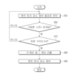
도 5는 본 발명의 일 실시예에 따른 트랙션 제어 시스템 의 제어 방법의 일부를 나타낸 순서도이다.
도 6은 본 발명의 다른 일 실시예에 따른 트랙션 제어 시스템 의 제어 방법의 일부를 나타낸 순서도이다.1 is a block diagram showing various electronic devices included in a vehicle including a traction control system according to an embodiment of the present invention.
Figure 2 is a block diagram of a traction control system according to an embodiment of the present invention.
Figure 3 is a graph showing road surface changes, vehicle speed, wheel spin, and longitudinal acceleration over time during traction control according to an embodiment of the present invention.
Figure 4 is a graph showing changes in control values over time during traction control according to an embodiment of the present invention.
Figure 5 is a flowchart showing part of a control method of a traction control system according to an embodiment of the present invention.
Figure 6 is a flowchart showing part of a control method of a traction control system according to another embodiment of the present invention.
이하에서는 본 발명의 실시 예를 첨부 도면을 참조하여 상세히 설명한다. 이하의 실시 예는 본 발명이 속하는 기술분야에서 통상의 지식을 가진 자에게 본 발명의 사상을 충분히 전달하기 위해 제시하는 것이다. 본 발명은 여기서 제시한 실시 예만으로 한정되지 않고 다른 형태로 구체화될 수도 있다. 도면은 본 발명을 명확히 하기 위해 설명과 관계없는 부분의 도시를 생략하고, 이해를 돕기 위해 구성요소의 크기를 다소 과장하여 표현할 수 있다.Hereinafter, embodiments of the present invention will be described in detail with reference to the accompanying drawings. The following examples are presented to sufficiently convey the idea of the present invention to those skilled in the art. The present invention is not limited to the embodiments presented herein and may be embodied in other forms. In order to clarify the present invention, the drawings may omit illustrations of parts unrelated to the description and may exaggerate the sizes of components somewhat to aid understanding.
도 1은 본 발명의 실시 예에 따른 트랙션 제어 시스템 (150)을 포함한 차량에 포함된 각종 전자 장치를 도시한 블록도이고, 도 2는 본 발명의 실시 예에 따른 트랙션 제어 시스템 의 블록도이다.FIG. 1 is a block diagram showing various electronic devices included in a vehicle including the
도 1에 도시된 바와 같이 차량(1)은 엔진 제어 모듈(engine control module)(110), 전자 제동 모듈(electronic braking module)(120), AVN장치 (Audio/Video/Navigation)(130), 공기 조화 장치(140), 트랙션 제어 시스템 (Steering Control system)(150), 변속 제어 모듈(160), 전동 조향 모듈(170), 가속/감속 장치(180), 입출력 제어 시스템(190), 및 기타 차량 센서(200) 등을 포함할 수 있다. As shown in FIG. 1, the
다만, 도 1에 도시된 전자 장치(100)는 차량(1)에 포함된 전자 장치의 일부에 불과하며 차량(1)에는 더욱 다양한 전자 장치가 마련될 수 있다.However, the
또한, 차량(1) 포함된 각종 전자 장치(100)는 차량 통신 네트워크(NT)를 통하여 서로 통신할 수 있다. Additionally, various
차량 통신 네트워크(NT)는 최대 24.5Mbps(Mega-bits per second)의 통신 속도를 갖는 모스트(MOST, Media Oriented Systems Transport), 최대 10Mbpas의 통신 속도를 갖는 플렉스레이(FlexRay), 125kbps(kilo-bits per second) 내지 1Mbps의 통신 속도를 갖는 캔(CAN, Controller Area Network), 20kbps의 통신 속도를 갖는 린(LIN, Local Interconnect Network) 등의 통신 규약을 채용할 수 있다. 이와 같은 차량 통신 네트워크(NT)는 모스트, 플레스레이, 캔, 린 등 단일의 통신 규약을 채용할 수 있을 뿐만 아니라, 복수의 통신 규약을 채용할 수도 있다.The vehicle communication network (NT) is MOST (Media Oriented Systems Transport) with a communication speed of up to 24.5Mbps (Mega-bits per second), FlexRay with a communication speed of up to 10Mbps, and 125kbps (kilo-bits). Communication protocols such as CAN (Controller Area Network) with a communication speed of 1Mbps to 1Mbps, and LIN (Local Interconnect Network) with a communication speed of 20kbps can be adopted. Such a vehicle communication network (NT) can not only adopt a single communication protocol such as Most, Plasray, Can, and Lean, but can also adopt multiple communication protocols.
엔진 제어 모듈(110)은 연료분사 제어, 연비 피드백 제어, 희박 연소 제어, 점화 시기 제어 및 공회전수 제어 등을 수행한다.The
전자 제동 모듈(120)은 차량(1)의 제동 장치를 제어할 수 있으며, 대표적으로 안티락 브레이크 시스템(Anti-lock Brake System, ABS) 등을 포함할 수 있다. The
AVN 장치(130)는 운전자의 제어 명령에 따라 음악 또는 영상을 출력하는 장치이다. 구체적으로, AVN 장치(130)는 운전자의 제어 명령에 따라 음악 또는 동영상을 재생하거나 본 발명에 따른 트랙션 제어 시스템 (150)을 통한 동작 상태를 운전자에게 표시해 줄 수 있다. The AVN
이러한 AVN 장치(130)는 AVN 디스플레이(미도시)를 포함할 수 있으며, AVN 디스플레이(미도시)는 운전자의 터치 입력을 수신할 수 있는 터치 감지 디스플레이(예를 들어, 터치 스크린)을 채용할 수 있다. This AVN
또한, AVN 디스플레이는 액정 디스플레이(Liquid Crystal Display: LCD) 패널 또는 유기 발광 다이오드(Organic Light Emitting Diode: OLED) 패널 등을 채용할 수 있다.Additionally, the AVN display may employ a Liquid Crystal Display (LCD) panel or an Organic Light Emitting Diode (OLED) panel.
다음으로, 공기 조화 장치(140)는 차량(1) 실내 온도에 따라 실내 공기를 가열하거나 냉각할 수 있다.Next, the
또한, 변속 제어 모듈(160)은 변속점 제어, 댐퍼 클러치 제어, 마찰 클러치 온/오프 시의 압력 제어 및 변속 중 엔진 토크 제어 등을 수행한다. 이러한 변속 제어 시스템(160)은 단일의 장치일 수 있을 뿐만 아니라, 통신을 통하여 연결된 복수의 장치들일 수도 있다.Additionally, the
또한, 전동 조향 모듈(170)은 저속 주행 또는 주차 시에는 조향력을 감소시키고 고속 주행 시에는 조향력을 증가시키는 등 사용자의 조향 조작을 보조할 수 있다.Additionally, the
다음으로, 가속/감속 장치(180)는 가속(Accelerator) 페달 및 브레이크(Brake) 페달을 포함하여, 운전자의 가속의지에 따른 페달 답력이 인가되면 차량을 가속시키고, 운전자의 감속의지에 따른 페달 답력이 인가되면 차량을 감속시킨다.Next, the acceleration/
구체적으로, 브레이크 페달은 운전자가 제동을 하기 위하여 발로 조작하는 페달로, 마스터 실린더의 피스톤을 밀어 유압이 발생되어 감속되도록 할 수 있다. 운전자의 발로 브레이크 페달(130)을 조작하는 답력을 답력 센서(미도시)로 측정하여 운전자의 제동 의지를 판단할 수 있다.Specifically, the brake pedal is a pedal that the driver operates with his or her foot to brake, and can push the piston of the master cylinder to generate hydraulic pressure to reduce speed. The driver's willingness to brake can be determined by measuring the pedal force used to operate the
또한, 가속(Accelerator) 페달은 운전자가 가속을 하기 위하여 발로 조작하는 페달로, 차량 내부의 기화기(카뷰레터)(미도시)와 연동된 기관이 가속 페달을 밟으면 회전이 빨라져 가속되도록 할 수 있다. 운전자의 발로 가속 페달)을 조작하는 답력을 답력 센서(미도시)로 측정하여 운전자의 가속 의지를 판단할 수 있다.In addition, the accelerator pedal is a pedal that the driver operates with his or her feet to accelerate. When the engine linked to the carburetor (not shown) inside the vehicle rotates faster and accelerates the vehicle, the vehicle can accelerate. The driver's willingness to accelerate can be determined by measuring the pedal effort used to operate the accelerator pedal with the driver's foot using a pedal force sensor (not shown).
입출력 제어 시스템(190)은 버튼을 통한 운전자의 제어 명령을 수신하고, 운전자의 제어 명령에 대응하는 정보를 표시한다. 입출력 제어 시스템(190)는 대시 보드에 마련되어 영상을 표시하는 클러스터 디스플레이(191), 영상을 윈드 스크린에 투영하는 헤드업 디스플레이(Head Up Display: HUD)(192)를 포함할 수 있다. The input/
클러스터(191)는 대시 보드에 마련되어 영상을 표시한다. 특히, 클러스터(191)는 윈드 스크린에 인접하여 마련됨으로써 운전자의 시선이 차량(1)의 전방으로부터 크게 벗어나지 않은 상태에서 운전자가 차량(1)의 동작 정보, 도로의 정보 또는 주행 경로 등을 획득할 수 있도록 한다. The
헤드업 디스플레이(192)는 영상을 윈드 스크린에 투영시킬 수 있다. 구체적으로, 헤드-업 디스플레이(192)에 의하여 윈드 스크린에 투영되는 영상은 차량(1)의 동작 정보, 도로의 정보 또는 주행 경로 등을 포함할 수 있고, 내비게이션 시스템으로부터 수신한 정보를 기초로 사용자에게 위치 정보를 안내하거나 경고할 수도 있다.The head-up
이외에, 도시되지 않았으나, 동력 전달 제어 모듈(미도시)는 변속 제어, 댐퍼 클러치 제어, 마찰 클러치 온/오프 시의 압력 제어 및 변속 중 엔진 토크 제어 등을 수행한다.In addition, although not shown, the power transmission control module (not shown) performs shift control, damper clutch control, pressure control when friction clutch is on/off, and engine torque control during shift.
기타 차량 센서(195)는 차량(1)에 포함되어 차량의 주행 정보를 감지하기 위하여 가속도 센서(196), 요레이트 센서(197), 조향각 센서(198) 및 속도 센서(199) 등을 포함할 수 있다.
가속도 센서(196)는 차량의 가속도를 측정하는 것으로, 횡 가속도 센서(미도시)와 종가속도 센서(미도시)를 포함할 수 있다. The
횡가속도 센서는 차량의 이동방향의 X축 이라고 할 때, 이동 방향의 수직축(Y축)방향을 횡방향이라고 하여 횡방향의 가속도를 측정한다. The lateral acceleration sensor measures acceleration in the lateral direction, assuming that the X-axis of the vehicle's moving direction is the vertical axis (Y-axis) of the moving direction.
종가속도 센서는 차량의 이동방향 X축 방향의 가속도를 측정할 수 있다.The longitudinal acceleration sensor can measure acceleration in the X-axis direction of the vehicle.
이러한 가속도 센서(196)는 단위시간당 속도의 변화를 검출하는 소자로써 가속도, 진동, 충격 등의 동적인 힘을 감지하며 관성력, 전기변형, 자이로(Gyro)의 원리를 이용하여 측정한다. This
요레이트 센서(197)는 차량의 각 휠에 설치될 수 있으며, 실시간으로 요레이트값을 검출할 수 있다.The
요레이트 센서(197)는 센서 내부에 셀슘 크리스탈 소자가 있으며, 차량이 움직이면서 회전을 하게 되면 셀슘 크리스탈 소자 자체가 회전을 하면서 전압을 발생한다. 이와 같이 발생된 전압을 기초로 차량의 요 레이트를 감지할 수 있다.The
조향각 센서(198)는 조향각을 측정한다. 스티어링 휠(미도시)의 하단부에 장착되며, 핸들의 조향 속도, 조향 방향 및 조향각을 검출할 수 있다. The
속도 센서(199)는 차량의 각 휠(FL, FR, RL, RR)의 안쪽에 설치되어 차량 바퀴의 회전 속도를 검출하며, 측정한 차속 값을 네트워크(NT)를 통하여 트랙션 제어 시스템 (150)으로 전송할 수 있다.The
마지막으로, 본 발명에 따른 트랙션 제어 시스템 (150)은 차량(1)에 포함된 기타 차량 센서(195)를 통하여 획득한 차량의 상태를 감지하여 휠의 스핀을 방지하기 위한 트랙션 제어를 수행하고, 특히, 마찰 노면을 파악하여 트랙션 제어의 토크 값을 적절히 제어한다. Finally, the
이상에서는 차량(1)의 구성에 대하여 설명하였다.In the above, the configuration of the
이하에서는 차량(1)에 포함된 트랙션 제어 시스템 (150)의 구성 및 동작에 대하여 설명한다.Hereinafter, the configuration and operation of the
도 2에 도시된 바와 같이, 본 발명에 따른 트랙션 제어 시스템 (150)은 통신부(151), 스위치부(152), 제어부(153) 및 구동부(156)를 포함한다. As shown in FIG. 2, the
먼저, 통신부(151)는 도 1 에 도시된 차량 통신 네트워크(NT)를 통하여 차량(1)에 포함된 각종 전자 장치(100)로부터 제어 신호를 수신 받고, 트랙션 제어 시스템(150)에서 생성한 제어 신호를 각종 전자 장치(100)로 송신한다.First, the
예를 들어, 속도 센서(199)에서 감지한 각 휠의 속도 및 가속도 센서(196)로부터 측정한 차량의 가속도를 통신부(151)를 통하여 수신한다. For example, the speed of each wheel detected by the
뿐만 아니라, 수신한 센서값을 기초로 트랙션 제어 시스템(150) 내에서 휠 스핀 발생 여부를 판단하고, 그에 따른 트랙션 제어 신호를 통신부(151)를 통하여 각종 전자 장치(100)로 송신할 수 있다.In addition, based on the received sensor value, the
다음으로, 스위치부(152)는 도시하지는 않았으나, 사용자가 트랙션 제어 시스템(150)의 ON/OFF에 대한 입력을 획득한다. 이에 따라, 사용자가 ON 동작을 선택하면 휠 스핀을 방지하기 위한 트랙션 제어 시스템(150)이 동작을 실행할 수 있다.Next, the
제어부(153)는 트랙션 제어 시스템 (150)을 총괄적으로 제어한다. 구체적으로, 제어부(152)는 통신부(151)로부터 획득한 차량에 포함된 각종 센서의 센서값을 기초로 휠의 스핀 여부 및 노면 마찰을 판단하여 토크 값을 산출하는 메인 프로세서(154)와 각종 데이터를 저장하는 메모리(155)를 포함한다.The
먼저, 메인 프로세서(154)는 센서부(151)로부터 수신한 센서값을 기초로 트랙션 제어 시스템 (150)을 총괄적으로 제어한다. First, the main processor 154 comprehensively controls the
먼저, 메인 프로세서(154)는 차량(1)이 현재 고마찰 노면에서 저마찰 노면으로 주행하는지 여부를 판단한다. 이를 위하여 메인 프로세서(154)는 통신부 (151)를 통하여 수신한 차량의 가속도 및 휠 속도를 기초로 판단할 수 있다.First, the main processor 154 determines whether the
구체적으로, 메인 프로세서(154)는 차량(1)이 고마찰 노면에서 저마찰 노면으로 전환된 노면을 주행하고 있는지 판단하기 위하여 1) 현재 차량이 고마찰 노면에서 주행하고 있는지 판단하고, 2) 고마찰 노면으로 판단된 상태에서 일정 시간 내에 저마찰 노면으로 전환되었는지를 판단한다.Specifically, in order to determine whether the
이 때, 1) 현재 차량이 고마찰 노면에서 주행하고 있는지 여부를 판단하기 위하여 메인 프로세서(154)는 기타 차량 센서(195)에 포함된 가속도 센서(196) 또는 비구동륜에 설치된 속도 센서(199)를 통하여 획득한 차량(1) 가속도 값을 검출한다.At this time, 1) in order to determine whether the vehicle is currently driving on a high-friction road surface, the main processor 154 uses the
이 때, 획득한 가속도가 미리 설정한 제 1 임계 시간 동안 미리 설정한 제 1임계 가속도를 초과하면 현재 차량이 고마찰 노면을 주행하고 있는 것으로 판단한다. 다만, 메인 프로세서(154)는 획득한 차량(1)의 가속도 값이 미리 설정한 제 1 임계 시간 동안 미리 설정한 제 1 임계 가속도를 초과하여 유지하는지 여부를 판단하기 위하여 주행 중 발생할 수 있는 노이즈를 제거하기 위하여 Hysteresis 또는 Filter를 사용하여 차량 주행 중의 외란을 제거할 수 있다.At this time, if the acquired acceleration exceeds the preset first critical acceleration during the preset first critical time, it is determined that the vehicle is currently traveling on a high friction road surface. However, the main processor 154 detects noise that may occur during driving in order to determine whether the acquired acceleration value of the
예를 들어, 도 3은 본 발명의 일 실시예에 따른 트랙션 제어 시 시간에 따른 노면 변화, 차속, 휠 스핀 및 종가속도를 나타낸 그래프이다. For example, Figure 3 is a graph showing road surface changes, vehicle speed, wheel spin, and longitudinal acceleration over time during traction control according to an embodiment of the present invention.
(a)는 차량의 가속도를 나타낸 그래프이고, (b)는 차량의 속도를, (c)는 구동륜의 휠 스핀을 나타낸 그래프이다.(a) is a graph showing the acceleration of the vehicle, (b) is a graph showing the speed of the vehicle, and (c) is a graph showing the wheel spin of the driving wheels.
이 때, t1 기준시점(단, 도 3 그래프에서는 t1 기준시점이라고 하였으나, 미리 설정한 제 1 임계 시간과 같이 구간으로 설정될 수 있다.)에서 차량(1)이 고마찰 노면에서 저마찰 노면으로 지속하여 주행되는 경우, t1 기준시점 통과 시 구동륜에 휠 스핀이 발생한 것을 확인할 수 있다. At this time, the
따라서, 구동륜의 휠 스핀을 최소화하기 위하여 메인 프로세서(154)는 엔진 토크를 조절한다. Therefore, the main processor 154 adjusts the engine torque to minimize wheel spin of the driving wheels.
따라서, 고 마찰 노면을 주행한 것으로 판단한 이후, 메인 프로세서(154)는 미리 설정한 제 2 임계시간 내에 차량의 가속도가 미리 설정한 제 2 임계 가속도 이하로 감소되면 차량(1)이 현재 고마찰인 노면에서 저마찰인 노면으로 전환된 노면을 주행 중인 것으로 판단한다. Therefore, after determining that the vehicle has driven on a high-friction road surface, the main processor 154 determines that the
특히, 고마찰 노면에서 저마찰 노면으로 전환 판단된 경우에 구동륜의 경우 휠 스핀이 크게 발생할 수 있어, 휠 스핀 발생을 신속하게 방지하기 위하여 메인 프로세서(154)는 엔진 토크를 저감한다.In particular, when it is determined that a high-friction road surface has been switched from a high-friction road surface to a low-friction road surface, significant wheel spin may occur in the case of the driving wheel, and the main processor 154 reduces engine torque in order to quickly prevent wheel spin.
구체적으로, 메인 프로세서(154)는 엔진 토크 저감량을 산출하기PI(Proportional-위하여 Integral) 제어 방법을 사용한다. 이는 비례 적분 제어를 말하는 것으로, P 제어(비례 제어)를 통하여 엔진 토크를 신속하게 저감할 수 있다. Specifically, the main processor 154 uses the PI (Proportional-to-Integral) control method to calculate the engine torque reduction amount. This refers to proportional integral control, and the engine torque can be quickly reduced through P control (proportional control).
특히, P 제어 시 사용되는 KP는 이득값 혹은 게인(gain)이라고 하는데, 기준 KP 에 노면 전환에 따른 요인(Factor)를 곱하여 최종 KP를 산출한다. 구체적으로, 메인 프로세서(154)가 산출하고자 하는 최종 KP는 후술하는 식 1에 의하여 설명할 수 있다.In particular, K P used in P control is called a gain value or gain, and the final K P is calculated by multiplying the standard K P by the factor according to the road surface change. Specifically, the final K P that the main processor 154 wishes to calculate can be explained by
(식 1)(Equation 1)
최종 KP= 기준 KP * Pfactor Final K P = Standard K P * P factor
단, 최종 Kp는 P 제어 시 적용할 최종 게인값을 의미하며, 기준 Kp는 P 제어 시 기준 게인값을 의미하며, Pfactor는 노면이 고마찰 노면에서 저마찰 노면으로 전환됨에 따라 게인 값을 증가시키기 위한 최대 시간에 따른 Calibration parameter를 의미한다.However, final K p refers to the final gain value to be applied during P control, standard K p refers to the standard gain value during P control, and P factor is the gain value as the road surface switches from a high-friction road surface to a low-friction road surface. It refers to the calibration parameter according to the maximum time to increase.
즉, 노면이 전환된 시점(0[sec])에서는 노면 전환 시 게인 값을 최대로 부여하기 위하여 P-Factor의 최대값을 부여하고, 시간이 지남에 따라 게인 값을 감소시켜 최종 시점에서는 P-Factor를 100%로 부여함에 따라, P기준값이 최종 P 제어값으로 산출되도록 할 수 있다. In other words, at the point when the road surface is switched (0[sec]), the maximum value of P-Factor is given to give the maximum gain value when the road surface is switched, and the gain value is reduced over time, so that at the final point, P-Factor is given the maximum value. By assigning the factor to 100%, the P standard value can be calculated as the final P control value.
또한, 메인 프로세서(154)는 노면이 고마찰 노면에서 저마찰 노면으로 전환되면, 전환된 노면에서 신속한 엔진 토크량을 산출하여야만 휠의 스핀을 적절한 수준으로 유지할 수 있다. 즉, 오차를 없애기 위하여 메인 프로세서(154)는 I 제어(적분 제어)를 동시에 실행한다. Additionally, when the road surface changes from a high-friction road surface to a low-friction road surface, the main processor 154 must quickly calculate the amount of engine torque on the changed road surface to maintain wheel spin at an appropriate level. That is, in order to eliminate errors, the main processor 154 simultaneously executes I control (integral control).
특히, I 제어 시 사용되는 KI는 이득값 혹은 게인(gain)이라고 하는데, 기준 KI 에 노면 전환에 따른 요인(Factor)를 곱하여 최종 KI를 산출한다. 구체적으로, 메인 프로세서(154)가 산출하고자 하는 최종 KI는 후술하는 식 2에 의하여 설명할 수 있다.In particular, K I used when controlling I is called a gain value or gain, and the final K I is calculated by multiplying the standard K I by a factor according to road surface transition. Specifically, the final K I that the main processor 154 wishes to calculate can be explained by Equation 2, which will be described later.
(식 2)(Equation 2)
최종 KI= 기준 KI * Ifactor Final K I = Standard K I * I factor
단, 최종 KI는 I 제어 시 적용할 최종 게인값을 의미하며, 기준 KI 는 I 제어 시 기준 게인값을 의미하며, I-FACTOR 는 구체적으로, 도 4에서 설명될 수 있다.However, the final K I refers to the final gain value to be applied when controlling I, and the standard K I means the reference gain value during I control, and I-FACTOR can be specifically explained in FIG. 4.
즉, 노면이 전환된 시점(0[sec])에서는 노면 전환 시 게인 값을 최대로 부여하기 위하여 I-Factor의 최대값을 부여하고, 시간이 지남에 따라 게인 값을 감소시켜 최종 시점에서는 I-Factor를 100%로 부여함에 따라, I기준값이 최종 I 제어값으로 산출되도록 할 수 있다. In other words, at the point when the road surface is switched (0 [sec]), the maximum value of I-Factor is given to maximize the gain value when the road surface is switched, and the gain value is reduced over time, so that at the final point, I- By assigning the factor to 100%, the I standard value can be calculated as the final I control value.
따라서, 메인 프로세서(154)는 (식 1) 및 (식 2)에서 산출한 최종 Kp 및 KI을 기초로 최종 엔진 토크량을 설정할 수 있다.Accordingly, the main processor 154 can set the final engine torque amount based on the final K p and K I calculated in (Equation 1) and (Equation 2).
다만, 메인 프로세서(154)는 차량(1)이 고마찰 노면에서 저마찰 노면으로 전환된 노면을 주행한 것으로 판단한 경우일지라도, 구동륜에서 스핀이 미리 설정한 제 1 스핀 임계값 보다 작거나 차량(1)의 가속도가 0보다 작은 경우에는 본 발명에 따라 P 제어값 및 I 제어값을 산출하는 단계를 수행하지 않을 수 있다.However, even when the main processor 154 determines that the
다음으로, 메모리(154)는 트랙션 제어 시스템 (150)의 프로그램 및 데이터를 기억한다. Next, memory 154 stores programs and data for
구체적으로, 메모리(미도시)는 S램(S-RAM), D램(D-RAM) 등의 휘발성 메모리뿐만 아니라 플래시 메모리, 롬(Read Only Memory), 이피롬(Erasable Programmable Read Only Memory: EPROM), 이이피롬(Electrically Erasable Programmable Read OnlyMemory: EEPROM) 등의 비휘발성 메모리를 포함할 수 있다.Specifically, memory (not shown) includes not only volatile memory such as S-RAM and D-RAM, but also flash memory, Read Only Memory (ROM), and Erasable Programmable Read Only Memory (EPROM). ), and non-volatile memory such as Electrically Erasable Programmable Read OnlyMemory (EEPROM).
비휘발성 메모리는 트랙션 제어 시스템 (150)의 동작을 제어하기 위한 제어 프로그램 및 제어 데이터를 반 영구적으로 저장할 수 있으며, 휘발성 메모리는 비휘발성 메모리로부터 제어 프로그램 및 제어 데이터를 불러와 임시로 기억하고, 메인 프로세서에서 출력하는 각종 제어 신호를 임시로 저장할 수 있다.The non-volatile memory can semi-permanently store the control program and control data for controlling the operation of the
이상에서는 본 발명에 따른 트랙션 제어 시스템 (150)의 구성에 대하여 설명하였다. Above, the configuration of the
이하 도 5 및 도 6에서는 본 발명의 실시예에 따른 트랙션 제어 시스템 (150)의 제어 방법의 순서도이다.5 and 6 below are flowcharts of a control method of the
구체적으로, 도 5는 트랙션 제어 시스템(150)이 노면 상황 판단에 따라 엔진 토크 감소 제어가 필요한지 여부를 판단하는 방법에 관한 순서도이며, 도 6은 트랙션 제어 시스템(150)이 엔진 토크 감소량을 결정하는 방법에 관한 순서도이다. Specifically, FIG. 5 is a flowchart of how the
먼저, 도 5에 도시된 바와 같이, 본 발명에 따른 트랙션 제어 시스템(150)은 차량(1)의 가속도를 획득한다(S10). 구체적으로, 메인 프로세서(154)는 속도 센서(199)에서 감지한 각 휠의 속도로부터 가속도를 산출하거나 가속도 센서(196)로부터 측정한 차량의 가속도를 통신부(151)를 통하여 수신할 수 있다.First, as shown in FIG. 5, the
따라서, 메인 프로세서(154)는 획득한 가속도를 기초로 차량(1)이 현재 고마찰 노면을 주행중인지 여부를 판단한다(S20). 구체적으로, 획득한 가속도가 미리 설정한 제 1 임계 시간 동안 미리 설정한 제 1임계 가속도를 초과하면 현재 차량이 고마찰 노면을 주행하고 있는 것으로 판단한다.Accordingly, the main processor 154 determines whether the
따라서, 고마찰 노면인 것으로 메인 프로세서(154)가 판단하면(S20의 예), 이후 차량(1)이 저 마찰 노면으로 전환된 노면을 주행 하는지를 판단한다(S40). 이는 메인 프로세서(154)가 미리 설정한 제 2 임계시간 내에 차량의 가속도가 미리 설정한 제 2 임계 가속도 이하로 감소되면 차량(1)이 현재 고마찰인 노면에서 저마찰인 노면으로 전환된 노면을 주행 중인 것으로 판단할 수 있다.Therefore, if the main processor 154 determines that the road surface is high friction (Yes in S20), it is then determined whether the
따라서, 고마찰 노면에서 저마찰 노면으로 전환된 주행을 하고 있다고 판단하면, 메인 프로세서(154)는 구동륜의 휠 스핀을 최소화하기 위하여 엔진 토크의 감소 제어가 필요한 것으로 판단한다(S50). Accordingly, when it is determined that driving has changed from a high-friction road surface to a low-friction road surface, the main processor 154 determines that engine torque reduction control is necessary to minimize wheel spin of the driving wheel (S50).
이 후 트랙션 제어 시스템(150)이 엔진 토크 감소량을 결정하는 방법에 관하여 도 6에서 후술한다. The method by which the
차량(1)이 고마찰 노면에서 저마찰 노면으로 전환된 노면을 주행하는 것으로판단한 이후(S50), 구동륜 스핀이 미리 설정한 임계값보다 크고(S60의 예), 차량(1)의 주행 가속도가 0 이상인 경우(S70의 예)인 경우에 트랙션 제어 시스템(150)은 본 발명에 따른 엔진 토크량을 결정하기 위하여 P 게인 및 I 게인을 산출한다(S80).After determining that the vehicle (1) is driving on a road surface that has changed from a high-friction road surface to a low-friction road surface (S50), the drive wheel spin is greater than the preset threshold (example of S60), and the driving acceleration of the vehicle (1) is lowered. If it is 0 or more (example in S70), the
다만, 차량(1)이 고마찰 노면에서 저마찰 노면으로 전환된 노면을 주행하는 것으로 판단한 이후(S50), 구동륜 스핀이 미리 설정한 임계값보다 작거나(S60의 아니오), 차량의 주행 가속도가 0 미만이면(S70의 아니오), 차량(1)의 구동륜에서 스핀이 발생할 가능성이 작으므로, 본 발명에 따른 트랙션 제어 시스템(150) 내 엔진 토크량을 결정하기 위하여 P 게인 및 I 게인을 산출하지 않고, 계속하여 엔진 토크 감소에 따른 토크 제어가 필요한지 여부를 판단한다.However, after it is determined that the vehicle (1) is driving on a road surface that has changed from a high-friction road surface to a low-friction road surface (S50), the drive wheel spin is less than a preset threshold (No in S60), or the driving acceleration of the vehicle is lowered. If it is less than 0 (No in S70), there is a small possibility that spin will occur in the driving wheel of the
이 때, P 게인(gain)과 I 게인(gain)이란, 엔진 토크 저감량을 산출하기PI(Proportional-위하여 Integral) 제어 방법을 사용 시, (식 1)을 통하여 산출한 비례 제어 시의 최종 KP 및 (식 2)를 통하여 산출한 적분 제어 시의 최종 KI를 의미한다. At this time, P gain and I gain are the final K P during proportional control calculated through (Equation 1) when using PI (Proportional-Integral) control method to calculate engine torque reduction. It means the final K I during integral control calculated through (Equation 2).
이 때, KP 및 KI 는 노면이 전환 시 게인 값을 최대로 부여하고, 시간이 지남에 따라 게인 값을 감소시키기 위한 Factor를 곱하여 최종 P 게인(gain)과 I 게인을 산출할 수 있다.At this time, K P and K I gives the maximum gain value when the road surface changes, and can calculate the final P gain and I gain by multiplying it by a factor to reduce the gain value over time.
따라서, 메인 프로세서(154)는 P 게인(gain)과 I 게인(gain)을 사용하여 엔진 토크 감소 제어를 수행하여 차량 구동륜의 스핀 발생을 신속하게 최소화할 수 있다. Accordingly, the main processor 154 can quickly minimize the occurrence of spin in the vehicle's driving wheels by performing engine torque reduction control using the P gain and I gain.
이상에서는 개시된 발명의 일 실시예에 대하여 도시하고 설명하였지만, 개시된 발명은 상술한 특정의 실시예에 한정되지 아니하며 청구범위에서 청구하는 요지를 벗어남 없이 개시된 발명이 속하는 기술 분야에서 통상의 지식을 가진 자에 의하여 다양한 변형실시가 가능함을 물론이고 이러한 변형실시들은 개시된 발명으로부터 개별적으로 이해될 수 없다.In the above, one embodiment of the disclosed invention has been shown and described, but the disclosed invention is not limited to the specific embodiment described above, and those skilled in the art in the technical field to which the disclosed invention pertains without departing from the gist of the claims. Of course, various modifications are possible, and these modifications cannot be understood individually from the disclosed invention.
1: 차량 100: 전자 장치
150: 트랙션 제어 시스템 1: Vehicle 100: Electronic Device
150: Traction control system
Claims (6)
상기 수신한 차량 가속도의 감소에 응답하여 출력 토크를 감소시키는 제어부;를 포함하고,
상기 제어부는 상기 차량 가속도를 기초로 고마찰 노면에서 전환된 저마찰 노면을 상기 차량이 주행하는 것으로 판단하면, 상기 감소된 차량 가속도에 대응하는 제 1 토크보다 작은 제 2 토크를 출력한 이후 미리 설정한 제 1 임계 시간 동안 상기 제 1 토크로 증가시키고,
상기 제어부는 상기 차량 가속도를 기초로 고마찰 노면에서 전환된 저마찰 노면을 상기 차량이 주행하는 것으로 판단한 이후, 구동륜 스핀이 미리 설정한 임계값보다 작거나 상기 차량 가속도가 0보다 작은 경우, 상기 출력 토크를 유지시키는 트랙션 제어 시스템.a communication unit that receives the acceleration of the vehicle; and
A control unit that reduces output torque in response to a decrease in the received vehicle acceleration,
When the control unit determines that the vehicle is driving on a low-friction road surface converted from a high-friction road surface based on the vehicle acceleration, it outputs a second torque smaller than the first torque corresponding to the reduced vehicle acceleration and then preset increasing the first torque for a first threshold time,
After the control unit determines that the vehicle is driving on a low-friction road surface converted from a high-friction road surface based on the vehicle acceleration, if the drive wheel spin is less than a preset threshold or the vehicle acceleration is less than 0, the output Traction control system to maintain torque.
상기 제어부는 상기 차량의 가속도가 미리 설정한 제 2 임계 시간 동안 미리 설정한 제 1 가속도 이상 유지한 이후, 미리 설정한 제 3 임계 시간 내에 미리 설정한 제 2 가속도보다 작아지면 상기 차량이 고마찰 노면에서 전환된 저마찰 노면을 주행하는 것으로 판단하는 트랙션 제어 시스템. According to claim 1,
The control unit maintains the acceleration of the vehicle above the preset first acceleration for a preset second threshold time, and then, if the vehicle is lower than the preset second acceleration within the third preset threshold time, the vehicle is driven on a high-friction road surface. A traction control system that determines that driving is on a low-friction road surface converted from .
상기 제 2 토크는 PI 제어(Proportional-Integral )방법에 의하여 산출되는 트랙션 제어 시스템. According to claim 1 or 2,
A traction control system in which the second torque is calculated by the PI control (Proportional-Integral) method.
상기 수신한 차량 가속도의 감소에 응답하여 출력 토크를 감소시키는 단계;를 포함하는 트랙션 제어 방법에 있어서,
상기 차량 가속도를 기초로 고마찰 노면에서 전환된 저마찰 노면을 상기 차량이 주행하는 것으로 판단하면, 상기 감소된 차량 가속도에 대응하는 제 1 토크보다 작은 제 2 토크를 출력한 이후 미리 설정한 제 1 임계 시간 동안 상기 제 1 토크로 증가시키는 단계;를 포함하고,
상기 제 1 토크로 증가시키는 단계는,
고마찰 노면에서 전환된 저마찰 노면을 상기 차량이 주행하는 것으로 판단한 이후, 구동륜 스핀이 미리 설정한 임계값보다 작거나 상기 차량 가속도가 0보다 작은 경우, 상기 출력 토크를 유지시키는 단계;를 더 포함하는 트랙션 제어 시스템의 제어 방법. receiving acceleration of the vehicle;
In a traction control method comprising: reducing output torque in response to a decrease in the received vehicle acceleration,
If it is determined that the vehicle is driving on a low-friction road surface converted from a high-friction road surface based on the vehicle acceleration, a second torque smaller than the first torque corresponding to the reduced vehicle acceleration is output, and then a preset first torque is generated. Increasing to the first torque for a threshold time,
The step of increasing the first torque is,
After determining that the vehicle is driving on a low-friction road surface converted from a high-friction road surface, if a drive wheel spin is less than a preset threshold or the vehicle acceleration is less than 0, maintaining the output torque; Control method of a traction control system.
상기 차량 가속도를 기초로 고마찰 노면에서 전환된 저마찰 노면을 상기 차량이 주행하는 것으로 판단하는 것은
상기 차량의 가속도가 미리 설정한 제 2 임계 시간 동안 미리 설정한 제 1 가속도 이상 유지한 이후, 미리 설정한 제 3 임계 시간 내에 미리 설정한 제 2 가속도보다 작아지면 상기 차량이 고마찰 노면에서 전환된 저마찰 노면을 주행하는 것으로 더 판단하는 트랙션 제어 시스템의 제어 방법. According to claim 4,
Based on the vehicle acceleration, it is judged that the vehicle is driving on a low-friction road surface that has been converted from a high-friction road surface.
If the acceleration of the vehicle is maintained above the preset first acceleration for a preset second threshold time and then becomes less than the preset second acceleration within a preset third threshold time, the vehicle switches from the high friction road surface. A control method of the traction control system that further determines driving on a low-friction road surface.
상기 제 2 토크는 PI 제어(Proportional-Integral )방법에 의하여 산출되는 트랙션 제어 시스템의 제어 방법.According to claim 4 or 5,
A control method of a traction control system in which the second torque is calculated by the PI control (Proportional-Integral) method.
Priority Applications (4)
| Application Number | Priority Date | Filing Date | Title |
|---|---|---|---|
| KR1020160160716A KR102677303B1 (en) | 2016-11-29 | 2016-11-29 | Traction control system and method thereof |
| CN201711226519.1A CN108116412B (en) | 2016-11-29 | 2017-11-29 | Traction control system and control method thereof |
| US15/825,280 US10723357B2 (en) | 2016-11-29 | 2017-11-29 | Traction control system and control method thereof |
| DE102017011061.1A DE102017011061A1 (en) | 2016-11-29 | 2017-11-29 | Traction control system and control method thereof |
Applications Claiming Priority (1)
| Application Number | Priority Date | Filing Date | Title |
|---|---|---|---|
| KR1020160160716A KR102677303B1 (en) | 2016-11-29 | 2016-11-29 | Traction control system and method thereof |
Publications (2)
| Publication Number | Publication Date |
|---|---|
| KR20180060800A KR20180060800A (en) | 2018-06-07 |
| KR102677303B1 true KR102677303B1 (en) | 2024-06-21 |
Family
ID=62117998
Family Applications (1)
| Application Number | Title | Priority Date | Filing Date |
|---|---|---|---|
| KR1020160160716A Active KR102677303B1 (en) | 2016-11-29 | 2016-11-29 | Traction control system and method thereof |
Country Status (4)
| Country | Link |
|---|---|
| US (1) | US10723357B2 (en) |
| KR (1) | KR102677303B1 (en) |
| CN (1) | CN108116412B (en) |
| DE (1) | DE102017011061A1 (en) |
Families Citing this family (2)
| Publication number | Priority date | Publication date | Assignee | Title |
|---|---|---|---|---|
| KR102042825B1 (en) | 2018-11-02 | 2019-11-11 | 현대오트론 주식회사 | Vehicle control system and method in low friction roads |
| KR20240176185A (en) * | 2023-06-15 | 2024-12-24 | 현대자동차주식회사 | Road surface severity estimation device |
Citations (2)
| Publication number | Priority date | Publication date | Assignee | Title |
|---|---|---|---|---|
| US20150239475A1 (en) * | 2014-02-21 | 2015-08-27 | Ford Global Technologies, Llc | Hybrid vehicle and method of operation |
| WO2016092602A1 (en) * | 2014-12-08 | 2016-06-16 | 日産自動車株式会社 | Hybrid vehicle control device and hybrid vehicle control method |
Family Cites Families (12)
| Publication number | Priority date | Publication date | Assignee | Title |
|---|---|---|---|---|
| US6141618A (en) * | 1994-03-31 | 2000-10-31 | Mazda Motor Corporation | Traction control system for vehicles |
| US5758014A (en) * | 1996-08-05 | 1998-05-26 | Delco Electronics Corp. | Electric vehicle traction control system and method |
| KR101003714B1 (en) | 2005-11-23 | 2010-12-24 | 주식회사 만도 | Slip Control Method of Automotive Traction Control System |
| KR101059785B1 (en) | 2006-04-25 | 2011-08-26 | 주식회사 만도 | Engine control method of traction system |
| CN101209683B (en) * | 2006-12-26 | 2011-06-15 | 比亚迪股份有限公司 | Electric automobile driving electric motor control method and control system thereof |
| US8682599B2 (en) * | 2008-06-30 | 2014-03-25 | Nissan Motor Co., Ltd. | Road surface friction coefficient estimating device and road surface friction coefficient estimating method |
| WO2010041989A1 (en) * | 2008-10-10 | 2010-04-15 | Volvo Lastvagnar Ab | Method and system for controlling a vehicle powertrain |
| CN102686444B (en) * | 2009-09-29 | 2015-11-25 | Hdd伺服电机有限公司 | Traction control module, the vehicle and the auxiliary method controlling the motion of the vehicle |
| DE102011081707A1 (en) * | 2011-08-29 | 2013-02-28 | Robert Bosch Gmbh | Method for assisting a driver of a motor vehicle |
| JP5906173B2 (en) * | 2012-11-02 | 2016-04-20 | 日立オートモティブシステムズ株式会社 | Vehicle control device |
| KR101518889B1 (en) * | 2013-07-11 | 2015-05-12 | 현대자동차 주식회사 | System and method of controlling starting of vehicle |
| JP6272203B2 (en) * | 2014-09-30 | 2018-01-31 | オートリブ日信ブレーキシステムジャパン株式会社 | Vehicle control device |
-
2016
- 2016-11-29 KR KR1020160160716A patent/KR102677303B1/en active Active
-
2017
- 2017-11-29 CN CN201711226519.1A patent/CN108116412B/en active Active
- 2017-11-29 DE DE102017011061.1A patent/DE102017011061A1/en active Pending
- 2017-11-29 US US15/825,280 patent/US10723357B2/en active Active
Patent Citations (2)
| Publication number | Priority date | Publication date | Assignee | Title |
|---|---|---|---|---|
| US20150239475A1 (en) * | 2014-02-21 | 2015-08-27 | Ford Global Technologies, Llc | Hybrid vehicle and method of operation |
| WO2016092602A1 (en) * | 2014-12-08 | 2016-06-16 | 日産自動車株式会社 | Hybrid vehicle control device and hybrid vehicle control method |
Also Published As
| Publication number | Publication date |
|---|---|
| CN108116412A (en) | 2018-06-05 |
| US10723357B2 (en) | 2020-07-28 |
| US20180148062A1 (en) | 2018-05-31 |
| CN108116412B (en) | 2021-06-11 |
| DE102017011061A1 (en) | 2018-05-30 |
| KR20180060800A (en) | 2018-06-07 |
Similar Documents
| Publication | Publication Date | Title |
|---|---|---|
| KR102272761B1 (en) | Vehicle and control method thereof | |
| KR102418028B1 (en) | Vehicle control system, and controlling method thereof | |
| CN109334656B (en) | Vehicle control method and device | |
| US10518771B2 (en) | System and method for controlling vehicle speed | |
| US10391884B2 (en) | Drive power control device for electric vehicle | |
| US8200408B2 (en) | System and method for active traction control of a vehicle | |
| US20130090828A1 (en) | Method for stabilizing a two-wheeled vehicle having a laterally slipping rear wheel | |
| US20150217766A1 (en) | Speed control system and method of operating the same | |
| JP2017517442A (en) | Control system and method | |
| CN110001645A (en) | The driving-force control apparatus of vehicle | |
| KR101425751B1 (en) | The device and method for driving control of vehicle | |
| WO2010061432A1 (en) | Travel control device for vehicle | |
| JP2014118065A (en) | Electronic control brake system and break control method | |
| JPWO2020217133A1 (en) | Control device and control method | |
| KR20190037460A (en) | Vehicle control system and method thereof | |
| CN111746546A (en) | Road surface condition estimation device | |
| KR102677303B1 (en) | Traction control system and method thereof | |
| KR20170016595A (en) | Radar system and method for controlling thereof in a vehicle | |
| KR102347655B1 (en) | Apparatus and method for suspension system control of asymmetric road | |
| US10919533B2 (en) | Vehicle control system and control method thereof | |
| US8085138B2 (en) | Display-image switching apparatus and method | |
| JP4530880B2 (en) | Vehicle motion state control device | |
| KR20170032569A (en) | Adaptive Cruise Control system and method for controlling thereof in a vehicle | |
| KR102554927B1 (en) | Estimating method of friction coefficient of road surface for vehicle | |
| JP4998091B2 (en) | Inter-vehicle distance control device |
Legal Events
| Date | Code | Title | Description |
|---|---|---|---|
| PA0109 | Patent application |
St.27 status event code: A-0-1-A10-A12-nap-PA0109 |
|
| PG1501 | Laying open of application |
St.27 status event code: A-1-1-Q10-Q12-nap-PG1501 |
|
| P22-X000 | Classification modified |
St.27 status event code: A-2-2-P10-P22-nap-X000 |
|
| PN2301 | Change of applicant |
St.27 status event code: A-3-3-R10-R13-asn-PN2301 St.27 status event code: A-3-3-R10-R11-asn-PN2301 |
|
| PN2301 | Change of applicant |
St.27 status event code: A-3-3-R10-R13-asn-PN2301 St.27 status event code: A-3-3-R10-R11-asn-PN2301 |
|
| A201 | Request for examination | ||
| PA0201 | Request for examination |
St.27 status event code: A-1-2-D10-D11-exm-PA0201 |
|
| D13-X000 | Search requested |
St.27 status event code: A-1-2-D10-D13-srh-X000 |
|
| D14-X000 | Search report completed |
St.27 status event code: A-1-2-D10-D14-srh-X000 |
|
| PN2301 | Change of applicant |
St.27 status event code: A-3-3-R10-R13-asn-PN2301 St.27 status event code: A-3-3-R10-R11-asn-PN2301 |
|
| R17-X000 | Change to representative recorded |
St.27 status event code: A-3-3-R10-R17-oth-X000 |
|
| E902 | Notification of reason for refusal | ||
| PE0902 | Notice of grounds for rejection |
St.27 status event code: A-1-2-D10-D21-exm-PE0902 |
|
| AMND | Amendment | ||
| P11-X000 | Amendment of application requested |
St.27 status event code: A-2-2-P10-P11-nap-X000 |
|
| P13-X000 | Application amended |
St.27 status event code: A-2-2-P10-P13-nap-X000 |
|
| E601 | Decision to refuse application | ||
| PE0601 | Decision on rejection of patent |
St.27 status event code: N-2-6-B10-B15-exm-PE0601 |
|
| X091 | Application refused [patent] | ||
| AMND | Amendment | ||
| P11-X000 | Amendment of application requested |
St.27 status event code: A-2-2-P10-P11-nap-X000 |
|
| P13-X000 | Application amended |
St.27 status event code: A-2-2-P10-P13-nap-X000 |
|
| PX0901 | Re-examination |
St.27 status event code: A-2-3-E10-E12-rex-PX0901 |
|
| PX0701 | Decision of registration after re-examination |
St.27 status event code: A-3-4-F10-F13-rex-PX0701 |
|
| X701 | Decision to grant (after re-examination) | ||
| GRNT | Written decision to grant | ||
| PR0701 | Registration of establishment |
St.27 status event code: A-2-4-F10-F11-exm-PR0701 |
|
| PR1002 | Payment of registration fee |
St.27 status event code: A-2-2-U10-U11-oth-PR1002 Fee payment year number: 1 |
|
| PG1601 | Publication of registration |
St.27 status event code: A-4-4-Q10-Q13-nap-PG1601 |
|
| R18 | Changes to party contact information recorded |
Free format text: ST27 STATUS EVENT CODE: A-5-5-R10-R18-OTH-X000 (AS PROVIDED BY THE NATIONAL OFFICE) |
|
| R18-X000 | Changes to party contact information recorded |
St.27 status event code: A-5-5-R10-R18-oth-X000 |