KR102674999B1 - Bolting apparatus - Google Patents
Bolting apparatus Download PDFInfo
- Publication number
- KR102674999B1 KR102674999B1 KR1020200158168A KR20200158168A KR102674999B1 KR 102674999 B1 KR102674999 B1 KR 102674999B1 KR 1020200158168 A KR1020200158168 A KR 1020200158168A KR 20200158168 A KR20200158168 A KR 20200158168A KR 102674999 B1 KR102674999 B1 KR 102674999B1
- Authority
- KR
- South Korea
- Prior art keywords
- bolt
- hole
- elastic
- bolting
- bolting device
- Prior art date
- Legal status (The legal status is an assumption and is not a legal conclusion. Google has not performed a legal analysis and makes no representation as to the accuracy of the status listed.)
- Active
Links
Images


Classifications
-
- F—MECHANICAL ENGINEERING; LIGHTING; HEATING; WEAPONS; BLASTING
- F16—ENGINEERING ELEMENTS AND UNITS; GENERAL MEASURES FOR PRODUCING AND MAINTAINING EFFECTIVE FUNCTIONING OF MACHINES OR INSTALLATIONS; THERMAL INSULATION IN GENERAL
- F16B—DEVICES FOR FASTENING OR SECURING CONSTRUCTIONAL ELEMENTS OR MACHINE PARTS TOGETHER, e.g. NAILS, BOLTS, CIRCLIPS, CLAMPS, CLIPS OR WEDGES; JOINTS OR JOINTING
- F16B5/00—Joining sheets or plates, e.g. panels, to one another or to strips or bars parallel to them
- F16B5/02—Joining sheets or plates, e.g. panels, to one another or to strips or bars parallel to them by means of fastening members using screw-thread
- F16B5/0266—Joining sheets or plates, e.g. panels, to one another or to strips or bars parallel to them by means of fastening members using screw-thread using springs
-
- B—PERFORMING OPERATIONS; TRANSPORTING
- B25—HAND TOOLS; PORTABLE POWER-DRIVEN TOOLS; MANIPULATORS
- B25B—TOOLS OR BENCH DEVICES NOT OTHERWISE PROVIDED FOR, FOR FASTENING, CONNECTING, DISENGAGING OR HOLDING
- B25B15/00—Screwdrivers
- B25B15/02—Screwdrivers operated by rotating the handle
-
- B—PERFORMING OPERATIONS; TRANSPORTING
- B25—HAND TOOLS; PORTABLE POWER-DRIVEN TOOLS; MANIPULATORS
- B25B—TOOLS OR BENCH DEVICES NOT OTHERWISE PROVIDED FOR, FOR FASTENING, CONNECTING, DISENGAGING OR HOLDING
- B25B23/00—Details of, or accessories for, spanners, wrenches, screwdrivers
- B25B23/005—Screw guiding means
-
- B—PERFORMING OPERATIONS; TRANSPORTING
- B25—HAND TOOLS; PORTABLE POWER-DRIVEN TOOLS; MANIPULATORS
- B25B—TOOLS OR BENCH DEVICES NOT OTHERWISE PROVIDED FOR, FOR FASTENING, CONNECTING, DISENGAGING OR HOLDING
- B25B23/00—Details of, or accessories for, spanners, wrenches, screwdrivers
- B25B23/02—Arrangements for handling screws or nuts
- B25B23/08—Arrangements for handling screws or nuts for holding or positioning screw or nut prior to or during its rotation
- B25B23/10—Arrangements for handling screws or nuts for holding or positioning screw or nut prior to or during its rotation using mechanical gripping means
-
- B—PERFORMING OPERATIONS; TRANSPORTING
- B25—HAND TOOLS; PORTABLE POWER-DRIVEN TOOLS; MANIPULATORS
- B25B—TOOLS OR BENCH DEVICES NOT OTHERWISE PROVIDED FOR, FOR FASTENING, CONNECTING, DISENGAGING OR HOLDING
- B25B3/00—Hand vices, i.e. vices intended to be held by hand; Pin vices
-
- F—MECHANICAL ENGINEERING; LIGHTING; HEATING; WEAPONS; BLASTING
- F16—ENGINEERING ELEMENTS AND UNITS; GENERAL MEASURES FOR PRODUCING AND MAINTAINING EFFECTIVE FUNCTIONING OF MACHINES OR INSTALLATIONS; THERMAL INSULATION IN GENERAL
- F16B—DEVICES FOR FASTENING OR SECURING CONSTRUCTIONAL ELEMENTS OR MACHINE PARTS TOGETHER, e.g. NAILS, BOLTS, CIRCLIPS, CLAMPS, CLIPS OR WEDGES; JOINTS OR JOINTING
- F16B5/00—Joining sheets or plates, e.g. panels, to one another or to strips or bars parallel to them
- F16B5/02—Joining sheets or plates, e.g. panels, to one another or to strips or bars parallel to them by means of fastening members using screw-thread
-
- H—ELECTRICITY
- H01—ELECTRIC ELEMENTS
- H01M—PROCESSES OR MEANS, e.g. BATTERIES, FOR THE DIRECT CONVERSION OF CHEMICAL ENERGY INTO ELECTRICAL ENERGY
- H01M50/00—Constructional details or processes of manufacture of the non-active parts of electrochemical cells other than fuel cells, e.g. hybrid cells
- H01M50/20—Mountings; Secondary casings or frames; Racks, modules or packs; Suspension devices; Shock absorbers; Transport or carrying devices; Holders
Landscapes
- Engineering & Computer Science (AREA)
- Mechanical Engineering (AREA)
- General Engineering & Computer Science (AREA)
- Chemical & Material Sciences (AREA)
- Chemical Kinetics & Catalysis (AREA)
- Electrochemistry (AREA)
- General Chemical & Material Sciences (AREA)
- Connection Of Plates (AREA)
- Details Of Spanners, Wrenches, And Screw Drivers And Accessories (AREA)
- Bolts, Nuts, And Washers (AREA)
Abstract
본 발명은, 테이블상에 배치되고, 드라이버 비트를 구비하는 작동부와, 볼트홀이 형성된 볼팅대상물과 접촉할 수 있도록 테이블상에 배치되고, 볼트홀로 볼트를 안내하기 위한 관통구를 구비하는 지그부와, 관통구에 삽입되어 배치되고, 그 내부에 볼트를 수용할 수 있도록 중공형으로 형성되며, 볼트의 수직을 유지시킬 수 있도록 아래로 갈수록 내경이 좁아지는 형상으로 경사진 내부면을 구비하고, 볼트를 아래로 이동시킬 때 내부면이 탄력적으로 벌어질 수 있도록 일부가 볼트의 이동방향으로 절개되는 가이드부, 및 가이드부의 절개된 부위의 주변 부위를 탄력적으로 지지하도록 가이드부의 외주면과 접촉되어 배치되는 탄성부를 포함하여 구성되는 볼팅 장치로서, 볼팅대상물에 대한 볼트의 수직도를 확보할 수 있는 볼팅 장치가 제시된다.The present invention is arranged on a table and includes an operating part including a driver bit, and a jig part arranged on the table so as to be in contact with a bolting object on which a bolt hole is formed and provided with a through hole for guiding a bolt to the bolt hole. It is inserted and disposed in the through hole, is formed in a hollow shape to accommodate a bolt therein, and has an inner surface inclined in a shape where the inner diameter narrows downward so as to maintain the verticality of the bolt, A guide part that is partly cut in the direction of movement of the bolt so that the inner surface can elastically open when the bolt is moved down, and a guide part placed in contact with the outer peripheral surface of the guide part to elastically support the area around the cut part of the guide part. A bolting device that includes an elastic portion and can secure the verticality of the bolt to the bolting object is presented.
Description
본 발명은 볼팅 장치에 관한 것으로서, 더욱 상세하게는 볼팅대상물에 대한 볼트의 수직도를 확보할 수 있는 볼팅 장치에 관한 것이다.The present invention relates to a bolting device, and more specifically, to a bolting device that can ensure the verticality of a bolt to a bolting object.
전기자동차와 같은 중대형 디바이스는 고출력 및 대용량의 동력원을 필요로 한다. 따라서, 중대형 디바이스는 복수개의 배터리 셀을 전기적으로 연결한 중대형 배터리 팩을 동력원으로 주로 사용한다.Medium-to-large devices such as electric vehicles require high-output and large-capacity power sources. Therefore, medium-to-large devices mainly use medium-to-large battery packs in which a plurality of battery cells are electrically connected as a power source.
중대형 배터리 팩이 중대형 디바이스가 요구하는 고출력 및 대용량을 만족하기 위해서는, 복수개의 배터리 셀이 직렬, 병렬 또는 직렬과 병렬이 혼합된 방식으로 연결되어야 하고, 연결된 상태에서 외부의 충격에 대하여 안정적인 구조를 유지할 수 있어야 한다.In order for a medium-to-large battery pack to satisfy the high output and large capacity required by medium-to-large devices, multiple battery cells must be connected in series, parallel, or a combination of series and parallel, and maintain a stable structure against external shock while connected. Must be able to.
한편, 중대형 배터리 팩은 예컨대 외부 하우징, 내부 케이스, 고정용프레임, 버스바, 인쇄회로기판 및 히트펌프 등을 비롯한 각종 부품들이 볼트로 체결되어 있다.Meanwhile, in medium-to-large battery packs, various parts, including external housing, internal case, fixing frame, bus bar, printed circuit board, and heat pump, are fastened with bolts.
이러한 중대형 배터리 팩이 외부 충격으로부터 안정적인 구조를 유지하기 위해서는 중대형 배터리 팩의 제조 시에 볼트 체결이 정확하게 이루어져야 한다.In order for these medium to large sized battery packs to maintain a stable structure from external shocks, bolts must be fastened accurately when manufacturing the medium to large sized battery packs.
예컨대 볼트 체결 시 볼트가 기울어진 상태에서 오체결되는 경우, 체결 중에 체결 부위가 기구적으로 파손될 수 있고, 그렇지 않더라도 체결 후 체결 부위에 유격이 생기거나 불필요한 하중이 가해질 수 있다. 따라서, 중대형 배터리 팩의 사용 중에 볼트 체결 부위가 쉽게 피로해질 수 있고, 중대형 디바이스의 운행 시 충격이 누적되면 체결 부위가 빠르게 파손될 수 있다.For example, if the bolt is incorrectly tightened while the bolt is tilted, the fastening part may be mechanically damaged during fastening, and even if this is not the case, a gap may occur in the fastening part after tightening or an unnecessary load may be applied. Therefore, the bolt fastening portion may easily become fatigued during use of a medium- or large-sized battery pack, and the fastening portion may be quickly damaged if shock accumulates during operation of a medium- or large-sized device.
본 발명의 배경이 되는 기술은 하기의 특허문헌에 게재되어 있다.The technology behind the present invention is published in the following patent documents.
본 발명은 볼팅대상물에 대한 볼트의 수직도를 확보할 수 있는 볼팅 장치를 제공한다.The present invention provides a bolting device that can ensure the verticality of the bolt to the bolting object.
본 발명의 실시 형태에 따른 볼팅 장치는, 테이블상에 배치되고, 드라이버 비트를 구비하는 작동부; 볼트홀이 형성된 볼팅대상물과 접촉할 수 있도록 상기 테이블상에 배치되고, 상기 볼트홀로 볼트를 안내하기 위한 관통구를 구비하는 지그부; 상기 관통구에 삽입되어 배치되고, 그 내부에 볼트를 수용할 수 있도록 중공형으로 형성되며, 볼트의 수직을 유지시킬 수 있도록 아래로 갈수록 내경이 좁아지는 형상으로 경사진 내부면을 구비하고, 볼트를 아래로 이동시킬 때 내부면이 탄력적으로 벌어질 수 있도록 일부가 볼트의 이동방향으로 절개되는 가이드부; 상기 가이드부의 절개된 부위의 주변 부위를 탄력적으로 지지하도록 상기 가이드부의 외주면과 접촉되어 배치되는 탄성부;를 포함하여 구성된다.A bolting device according to an embodiment of the present invention includes an operating unit disposed on a table and provided with a driver bit; a jig portion disposed on the table so as to be in contact with a bolting object in which a bolt hole is formed, and having a through hole for guiding a bolt into the bolt hole; It is inserted and disposed in the through hole, is formed in a hollow shape to accommodate a bolt therein, and has an inner surface inclined in a shape where the inner diameter narrows downward so as to maintain the verticality of the bolt, and the bolt A guide part partially cut in the direction of movement of the bolt so that the inner surface can elastically open when moving downward; It is configured to include; an elastic part disposed in contact with the outer peripheral surface of the guide part to elastically support the surrounding area of the cut part of the guide part.
상기 탄성부는, 상기 관통구의 내벽에 오목하게 형성되는 설치홈; 및 상기 볼트의 이동방향과 교차하는 방향으로 연장형성되고, 상기 관통구의 내부로 돌출될 수 있도록 상기 설치홈에 내장되며, 상기 가이드부의 하단을 지지하는 탄성스프링;을 포함하여 구성될 수 있다.The elastic portion includes an installation groove concavely formed on the inner wall of the through hole; and an elastic spring that extends in a direction intersecting the moving direction of the bolt, is built into the installation groove so as to protrude into the interior of the through hole, and supports the lower end of the guide portion.
상기 설치홈은 복수개 형성되고, 상기 관통구를 중심으로 방사상으로 배치되며, 상기 탄성스프링은 복수개 구비되고, 상기 관통구를 중심으로 방사상으로 배치되어 각각의 설치홈에 내장되며, 각각의 일단이 설치홈 내벽에 지지되고, 각각의 타단이 상기 가이드부의 하단과 접촉될 수 있다.The installation grooves are formed in plural numbers and are arranged radially around the through hole. The elastic springs are provided in plural numbers, are arranged radially around the through hole and are built into each installation groove, and each end is installed. It is supported on the inner wall of the groove, and the other end of each may be in contact with the lower end of the guide portion.
상기 탄성부는, 상기 가이드부의 하단의 외주면을 감싸도록 배치되는 탄성링;을 포함하여 구성될 수 있다.The elastic portion may be configured to include an elastic ring disposed to surround an outer peripheral surface of a lower end of the guide portion.
상기 가이드부는, 볼트의 헤드 끝단과 접촉할 수 있도록 내경의 크기가 볼트의 헤드 크기와 동일한 상부 몸체; 및 수축 시에 볼트의 나사 하단과 접촉할 수 있도록 수축 시 내경의 크기가 볼트의 나사 크기와 동일한 하부 몸체;를 포함하여 구성될 수 있다.The guide portion includes an upper body whose inner diameter is the same as the head of the bolt so as to contact the end of the head of the bolt; and a lower body whose inner diameter when contracted is the same as the screw size of the bolt so that it can contact the bottom of the screw of the bolt when contracted.
상기 하부 몸체는 일부가 볼트의 이동방향으로 절개됨에 의해 복수개의 분체로 나누어지고, 상기 하부 몸체의 복수개의 분체는 상기 상부 몸체의 둘레를 따라 나열되어 상호 이격될 수 있다.The lower body is divided into a plurality of powders by cutting a portion in the direction of movement of the bolt, and the plurality of powders of the lower body may be arranged along the circumference of the upper body and spaced apart from each other.
상기 하부 몸체의 복수개의 분체는 상기 탄성부에 의해 탄성지지되며, 각각의 하단이 볼트의 헤드가 아래로 이동함에 의해 서로 멀어지는 방향으로 벌어질 수 있다.The plurality of powders of the lower body are elastically supported by the elastic portion, and the lower ends of each may be opened in a direction away from each other as the head of the bolt moves downward.
상기 하부 몸체의 복수개의 분체 각각은 상단과 하단 사이가 탄력적으로 벤딩될 수 있다.Each of the plurality of powders in the lower body can be elastically bent between the top and bottom.
상기 관통구와 상기 볼팅홀의 상하정렬을 진단할 수 있도록 상기 볼팅대상물 및 상기 지그부에 형성되는 얼라인부;를 더 포함하여 구성될 수 있다.It may further include an alignment portion formed on the bolting object and the jig portion to diagnose the vertical alignment of the through hole and the bolting hole.
상기 탄성부의 복수개의 탄성스프링의 길이 변화를 이용하여 볼트의 수직을 진단할 수 있도록 지그부에 설치되는 진단부;를 더 포함하여 구성될 수 있다.It may further include a diagnostic unit installed on the jig unit to diagnose the verticality of the bolt using changes in the length of the plurality of elastic springs of the elastic unit.
본 발명의 실시 형태에 따르면, 볼트의 수직을 유지시킬 수 있도록 아래로 갈수록 내경이 좁아지는 형상으로 경사진 내부면을 구비하는 가이드부를 지그부의 관통구 내부에 배치하고, 가이드부를 이용하여 볼팅대상물의 볼트홀로 볼트를 안내함으로써 볼트를 볼트홀에 체결시키는 동안 볼팅대상물에 대한 볼트의 수직도를 확보할 수 있다.According to an embodiment of the present invention, a guide part having an inner surface inclined in a shape where the inner diameter narrows downward so as to maintain the verticality of the bolt is disposed inside the through hole of the jig part, and the guide part is used to control the bolting object. By guiding the bolt to the bolt hole, the verticality of the bolt to the bolting object can be ensured while fastening the bolt to the bolt hole.
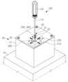
도 1은 본 발명의 제1실시 예에 따른 볼팅 장치의 개략도이다.
도 2는 본 발명의 제1실시 예에 따른 볼팅 장치의 분해도이다.
도 3은 본 발명의 제1실시 예에 따른 볼팅 장치의 부분 확대도이다.
도 4 내지 도 6은 본 발명의 제1실시 예에 따른 볼팅 장치의 모식도이다.
도 7은 본 발명의 제2실시 예에 따른 볼팅 장치의 부분 확대도이다.
도 8 내지 도 9는 본 발명의 제2실시 예에 따른 볼팅 장치의 모식도이다.
도 10은 본 발명의 제3실시 예에 따른 볼팅 장치의 모식도이다.
도 11은 본 발명의 제4실시 예에 따른 볼팅 장치의 모식도이다.
도 12는 본 발명의 제5실시 예에 따른 볼팅 장치의 모식도이다.
도 13은 본 발명의 제6실시 예에 따른 볼팅 장치의 모식도이다.1 is a schematic diagram of a bolting device according to a first embodiment of the present invention.
Figure 2 is an exploded view of the bolting device according to the first embodiment of the present invention.
Figure 3 is a partial enlarged view of the bolting device according to the first embodiment of the present invention.
4 to 6 are schematic diagrams of a bolting device according to a first embodiment of the present invention.
Figure 7 is a partial enlarged view of the bolting device according to the second embodiment of the present invention.
8 to 9 are schematic diagrams of a bolting device according to a second embodiment of the present invention.
Figure 10 is a schematic diagram of a bolting device according to a third embodiment of the present invention.
Figure 11 is a schematic diagram of a bolting device according to a fourth embodiment of the present invention.
Figure 12 is a schematic diagram of a bolting device according to a fifth embodiment of the present invention.
Figure 13 is a schematic diagram of a bolting device according to a sixth embodiment of the present invention.
이하, 첨부된 도면을 참조하여, 본 발명의 실시 예를 상세히 설명한다. 그러나 본 발명은 이하에서 개시되는 실시 예에 한정되는 것이 아니고, 서로 다른 다양한 형태로 구현될 것이다. 단지 본 발명의 실시 예는 본 발명의 개시가 완전하도록 하고, 해당 분야에서 통상의 지식을 가진 자에게 발명의 범주를 완전하게 알려주기 위해 제공되는 것이다. 본 발명의 실시 예를 설명하기 위하여 도면은 과장될 수 있고, 설명과 관계없는 부분은 도면에서 생략될 수 있고, 도면상의 동일한 부호는 동일한 요소를 지칭한다.Hereinafter, embodiments of the present invention will be described in detail with reference to the attached drawings. However, the present invention is not limited to the embodiments disclosed below, and will be implemented in various different forms. Only the embodiments of the present invention are provided to ensure that the disclosure of the present invention is complete and to fully inform those skilled in the art of the scope of the invention. In order to explain embodiments of the present invention, the drawings may be exaggerated, parts unrelated to the description may be omitted from the drawings, and the same symbols in the drawings refer to the same elements.
이하, 도면을 참조하여 본 발명의 실시 예들을 설명하도록 한다.Hereinafter, embodiments of the present invention will be described with reference to the drawings.
<제1실시 예><First embodiment>
1. 본 발명의 제1실시 예에 따른 볼팅 장치1. Bolting device according to the first embodiment of the present invention
도 1은 본 발명의 제1실시 예에 따른 볼팅 장치의 개략도이다. 도 2는 본 발명의 제1실시 예에 따른 볼팅 장치의 분해도이다. 도 3은 본 발명의 제1실시 예에 따른 볼팅 장치의 부분 확대도이다.1 is a schematic diagram of a bolting device according to a first embodiment of the present invention. Figure 2 is an exploded view of the bolting device according to the first embodiment of the present invention. Figure 3 is a partial enlarged view of the bolting device according to the first embodiment of the present invention.
도 1 내지 도 3을 참조하여, 본 발명의 제1실시 예에 따른 볼팅 장치를 상세하게 설명한다.1 to 3, a bolting device according to a first embodiment of the present invention will be described in detail.
본 발명의 제1실시 예에 따른 볼팅 장치는, 테이블(10)상에 배치되고, 드라이버 비트(110)를 구비하는 작동부(100), 볼트홀(H1)이 형성된 볼팅대상물과 접촉할 수 있도록 테이블(10)상에 배치되고, 볼트홀(H1)로 볼트(30)를 안내하기 위한 관통구(H2)를 구비하는 지그부(200), 관통구(H2)에 삽입되어 배치되고, 그 내부에 볼트(30)를 수용할 수 있도록 중공형으로 형성되며, 볼트(30)의 수직을 유지시킬 수 있도록 아래로 갈수록 내경이 좁아지는 형상으로 경사진 내부면을 구비하고, 볼트(30)를 아래로 이동시킬 때 내부면이 탄력적으로 벌어질 수 있도록 일부가 볼트(30)의 이동방향으로 절개되는 가이드부(300), 가이드부(300)의 절개된 부위(S)의 주변 부위를 탄력적으로 지지하도록 가이드부(300)의 외주면과 접촉되어 배치되는 탄성부(400)를 포함하여 구성된다.The bolting device according to the first embodiment of the present invention is disposed on the table 10, and has an
여기서, 테이블(10)은 볼팅대상물을 안착시킬 수 있도록 소정의 면적을 가지는 상면을 구비할 수 있다. 볼팅대상물은 테이블(10)의 상면에 안착될 수 있다. 볼팅대상물은 배터리팩(20)일 수 있다. 배터리팩(20)은 배터리팩 하우징(21)과 배터리팩 커버(22)를 포함하여 구성될 수 있다. 배터리팩 커버(22)의 상면에는 하나 이상의 홀이 관통형성될 수 있다. 배터리팩 커버(22)의 홀과 연결되도록 배터리팩 하우징(21)의 상단에도 하나 이상의 홀이 관통형성될 수 있다. 배터리팩 커버(22)의 홀과 배터리팩 하우징(21)의 홀이 상호 연결되어 볼트홀(H1)을 형성할 수 있다. 볼트홀(H1)의 내주면에는 나사산이 구비될 수 있다. 볼트(30)는 볼트홀(H1)에 나사결합될 수 있고, 이에 의하여 배터리팩 하우징(21)과 배터리팩 커버(22)가 상호 결합되어 배터리팩(20)을 형성할 수 있다. 배터리팩(20)의 내부에는 하나 이상의 단위 배터리 셀이 구비되어 있을 수 있다.Here, the table 10 may have an upper surface having a predetermined area so as to seat the bolting object. The bolting object may be seated on the upper surface of the table 10. The bolting object may be a
한편, 볼팅대상물은 배터리팩(20) 외에도 다양할 수 있다.Meanwhile, the bolting object may be diverse in addition to the
볼트(30)는 헤드(31) 및 나사(32)를 포함하여 구성된다. 헤드(31)는 상면에 일자홈 및 십자홈 중 어느 하나가 형성될 수 있다. 헤드(31)의 일자홈 또는 십자홈에 드라이버 비트(110)가 삽입될 수 있고, 드라이버 비트(110)의 회전에 의하여 헤드(31)가 회전되며 나사(32)를 회전시킬 수 있다. 나사(32)는 환봉 및 나선형의 나사산을 포함하여 구성될 수 있다. 환봉은 헤드(31)의 하면으로부터 하방으로 연장형성될 수 있다. 나사산은 환봉의 외주면에 나선형의 구조로 형성될 수 있다. 드라이브 비트(110)에 의해 헤드(31)가 회전하면 나사(32)도 동일하게 회전하면서 나사산에 의해 볼트홀(H1)의 내부로 전진할 수 있다. 물론, 볼트(30)는 그 구조가 다양할 수 있다.The
1.1. 본 발명의 제1실시 예에 따른 작동부(100)1.1.
작동부(100)는 수동 드라이버일 수 있다. 작동부(100)는 드라이버 비트(110) 및 작동부 몸체(120)를 포함하여 구성될 수 있다. 드라이버 비트(110)는 예컨대 생크(shank) 및 드라이버 팁을 포함하여 구성될 수 있다. 생크의 하단에 드라이버 팁이 형성될 수 있다. 드라이버 팁은 볼트(30)의 헤드(31)에 구비된 일자홈 또는 십자홈에 삽입되어 결합될 수 있다. 물론, 드라이버 팁의 형상은 십자 형상, 일자 형상, 사각 형상 및 육각 형상 등 다양할 수 있다. 또한, 드라이버 팁의 형상에 따라서 볼트(30)의 헤드(31)에 구비된 홈의 형상도 십자홈 형상, 일자홈 형상, 사각홈 형상 및 육각홈 형상 등 다양할 수 있다. 생크의 상단은 작동부 몸체(120)에 탈착가능하게 결합될 수 있다.The
한편, 작동부(100)는 전동 드라이버일 수도 있다. 작동부(100)가 전동 드라이버인 경우, 작동부 몸체(120)의 내부에는 회전 모터가 구비되고, 회전 모터가 생크의 상단과 연결될 수 있다. 회전 모터는 소정의 전선을 통해 전원 공급기와 연결될 수 있다. 작동부 몸체(120)의 외주면에는 버튼이 구비되고, 버튼을 눌러서 전선으로 전류를 흐르게 하여 회전 모터를 회전시킬 수 있다.Meanwhile, the
이러한 작동부(100)는 테이블(10)의 상측으로 소정 높이 이격배치되며, 로봇암(미도시) 혹은 작업자(미도시)에 의하여 작동될 수 있다.These operating
1.2. 본 발명의 제1실시 예에 따른 지그부(200)1.2.
지그부(200)는 배터리팩 커버(22)의 상면에 안착될 수 있다. 지그부(200)는 블록(210) 및 서포트(220)를 포함하여 구성될 수 있다. 블록(210)는 서포트(220)에 지지될 수 있다. 서포트(220)를 배터리팩 커버(22)에 대하여 상대 이동시키는 방식으로, 블록(210)의 위치를 수평방향으로 조절할 수 있다. 서포트(220)는 소정의 로봇암에 의하여 이동 및 고정되거나, 작업자에 의해 이동 및 고정될 수 있다.The
블록(210)은 수평방향으로 소정 면적을 가질 수 있고, 상하방향으로 소정 두께를 가질 수 있다. 블록(210)의 중심을 상하방향으로 관통하도록 관통구(H2)가 형성될 수 있다. 관통구(H2)의 내경은 볼트홀(H1)의 내경보다 클 수 있다.The
블록(210)은 관통구(H2)를 통하여 가이드부(300)를 수용하고, 가이드부(300)의 위치를 볼트홀(H1)의 중심축(L)에 상하방향으로 정렬시킬 수 있고, 볼트(30)가 볼트홀(H1)에 나사결합되는 동안 가이드부(300)를 지지할 수 있다.The
1.3. 본 발명의 제1실시 예에 따른 가이드부(300)1.3.
가이드부(300)는 관통구(H2)의 내부에서 볼트(30)를 지지하며, 볼트홀(H1)까지 볼트(30)를 안내하는 역할을 한다. 가이드부(300)는 그 내부에 볼트(30)를 수용할 수 있도록 중공형으로 형성될 수 있다. 가이드부(300)는 위에서 아래로 갈수록 점차 내경이 좁아지는 형상으로 형성될 수 있다. 따라서, 가이드부(300)는 내부면이 경사질 수 있다. 이에, 볼트(30)가 가이드부(300)의 내부에서 내부면에 지지되어 수직을 유지할 수 있다. 상세하게는 볼트(30)의 헤드의 끝단이 가이드부(300)의 내부면의 상부에 접촉하여 지지될 수 있고, 볼트(30)의 나사 하단이 가이드부(300)의 내부면의 하부와 접촉하여 지지될 수 있다. 이에, 볼트(30)의 수직이 유지될 수 있다. 이러한 가이드부(300)는 볼트(30)를 아래로 이동시킬 때 그 내부면이 탄력적으로 벌어질 수 있도록 일부가 볼트(30)의 이동방향을 따라 절개될 수 있다.The
또한, 가이드부(300)는 탄력을 가지는 소정의 재질로 형성될 수 있고, 이에, 볼트(30)의 헤드(31)의 위치에 따라 그 내부면이 서로 가까워지는 방향으로 조여지거나 서로 멀어지는 방향으로 벌어지는 동안, 파손을 방지할 수 있다. 여기서 탄력을 가지는 소정의 재질은 예컨대 실리콘 재질, 수지 재질 및 플라스틱 재질을 포함하여 다양할 수 있다.In addition, the
가이드부(300)는, 볼트(30)의 헤드(31) 끝단과 접촉할 수 있도록 내경의 크기가 볼트의 헤드 크기(D31)와 동일한 상부 몸체(310), 및 수축 시에 볼트(30)의 나사(32) 하단과 접촉할 수 있도록 수축 시 내경의 크기가 볼트의 나사 크기(D32)와 동일한 하부 몸체(320)를 포함하여 구성될 수 있다.The
상부 몸체(310)는 중공형으로 형성될 수 있고, 상부에서 하부로 갈수록 내경 및 외경이 점진적으로 좁아질 수 있다. 상부 몸체(310)는 수평단면이 링 형상일 수 있다. 상부 몸체(310)의 하단의 내경은 볼트의 헤드 크기(D31)와 동일할 수 있고, 상단의 내경은 하단의 내경보다 클 수 있다.The
하부 몸체(320)는 상부 몸체(310)의 하단으로부터 하방으로 연장형성될 수 있다. 하부 몸체(320)는 일부가 볼트(30)의 이동방향으로 절개됨에 의해 복수개의 분체로 나누어질 수 있다. 하부 몸체(320)의 복수개의 분체는 상부 몸체(310)의 둘레를 따라 나열되어 상호 이격될 수 있다.The
볼트(30)의 헤드(31)가 상부 몸체(310)에 위치할 때, 하부 몸체(320)의 하단의 내경은 볼트의 나사 크기(D32)와 동일할 수 있다. 여기서, 하부 몸체(320)의 하단의 내경을 예컨대 볼트(30)의 헤드(31)가 상부 몸체(310)에 위치할 때의 하부 몸체(320)의 복수개의 분체의 하단이 서로 마주보며 이격되어 있는 이격 간격이라고 표현할 수도 있다.When the
하부 몸체(320)의 절개된 부위(S)는 상부 몸체(310)의 둘레를 따라 이격되어 위치할 수 있고, 하부 몸체(320)의 상단부터 하단까지 연장되어 형성될 수 있다. 하부 몸체(320)의 절개된 부위(S)에 의해, 하부 몸체(320)의 복수개의 분체의 하단의 움직임이 서로 구속되지 않을 수 있다.The cut portion S of the
하부 몸체(320)의 복수개의 분체는 탄성부(400)에 의해 탄성지지될 수 있다. 이때, 하부 몸체(320)의 복수개의 분체 각각의 하단은, 볼트(30)의 헤드(310)가 상부 몸체(310)로부터 하부 몸체(320)로 진입한 이후에, 볼트(30)의 헤드(310)가 아래로 이동함에 의해 서로 멀어지는 방향으로 벌어질 수 있다. 하부 몸체(320)의 복수개의 분체 각각의 하단이 서로 멀어지는 방향으로 벌어지는 것을 팽창이라 한다.The plurality of powders in the
이때, 하부 몸체(320)의 복수개의 분체가 볼트(30)의 헤드(310)에 의해 서로 멀어지는 방향으로 벌어질 때, 하부 몸체(320)의 복수개의 분체 각각의 하단의 서로 마주보며 이격되어 있는 이격 간격을 하부 몸체(320)의 팽창 시 내경의 크기라고 하고, 그 크기는 볼트의 헤드 크기(D31)와 동일할 수 있다.At this time, when the plurality of powders of the
한편, 하부 몸체(320)의 복수개의 분체 각각의 하단은 볼트(30)의 헤드(310)가 상부 몸체(310)에 위치하고 있을 때에, 탄성부(400)에 의해 탄성지지되며 서로 가까워지는 방향으로 조여질 수 있다.Meanwhile, when the
이때, 하부 몸체(320)의 복수개의 분체 각각의 하단이 서로 가까워지는방향으로 조여질 때, 하부 몸체(320)의 복수개의 분체 각각의 하단의 서로 마주보며 이격되어 있는 이격 간격을 하부 몸체(320)의 수축 시 내경의 크기라 하고, 그 크기는 볼트의 나사 크기(D32)와 동일할 수 있다.At this time, when the lower ends of each of the plurality of powders of the
이처럼 하부 몸체(320)의 복수개의 분체 각각의 하단은 볼트(30)의 헤드(31)의 위치에 따라 서로 가까워지는 방향으로 조여지거나 서로 멀어지는 방향으로 벌어지면서, 볼트(30)의 수직 상태를 항상 유지시킬 수 있다.In this way, the lower ends of each of the plurality of powders of the
1.4. 본 발명의 제1실시 예에 따른 탄성부(400)1.4.
탄성부(400)는 가이드부(300)의 하부 몸체(320)의 팽창 시 및 수축 시 하부 몸체(320)를 탄력적으로 지지해주는 역할을 한다. 탄성부(400)는 관통구(H2)의 내벽에 오목하게 형성되는 설치홈(410), 및 볼트(30)의 이동방향과 교차하는 방향으로 연장형성되고, 관통구(H2)의 내부로 돌출될 수 있도록 설치홈(420)에 내장되며, 가이드부(300)의 하단을 지지하는 탄성스프링(420)을 포함하여 구성될 수 있다.The
설치홈(410)은 블록(210)의 내부에 복수개 형성되고, 관통구(H2)를 중심으로 방사상으로 배치될 수 있다. 탄성스프링(420)은 복수개 구비되고, 관통구(H2)를 중심으로 방사상으로 배치되며, 각각의 설치홈(410)에 내장될 수 있다. 이때, 탄성스프링(420)은 각각의 일단이 설치홈(410) 내벽에 지지될 수 있고, 각각의 타단이 가이드부(300)의 하부 몸체(320)의 하단과 접촉될 수 있다. 이에, 복수개의 탄성스프링(420)은 가이드부(300)의 하부 몸체(320)의 복수개의 분체를 균일하게 탄성 지지해줄 수 있다.A plurality of
1.5. 본 발명의 제1실시 예에 따른 볼팅 장치의 작동 방식1.5. Operating method of the bolting device according to the first embodiment of the present invention
도 4 내지 도 6은 본 발명의 제1실시 예에 따른 볼팅 장치의 작동을 설명하기 위한 모식도이다.4 to 6 are schematic diagrams for explaining the operation of the bolting device according to the first embodiment of the present invention.
도 4를 참조하면, 볼트(30)를 볼팅하고자 하는 볼트홀(H1)상에 관통구(H2)가 상하정렬되도록 지그부(200)을 이동시켜, 배터리팩 커버(22)의 상면에 지그부(200)를 위치시킨다. 이때, 가이드부(300)의 상부 몸체(310)의 하단 내경은 볼트(30)의 헤드(31)의 외경 즉, 헤드 크기(D31)와 동일할 수 있다. 또한, 가이드부(300)의 하부 몸체(320)의 하단 내경은 볼트(30)의 나사(32)의 외경 즉, 나사 크기(D32)와 동일할 수 있다. 이때, 가이드부(300)의 하부 몸체(320)의 하단은 탄성부(400)의 탄성스프링(420)에 의해 탄력적으로 지지된 상태일 수 있다.Referring to FIG. 4, the
도 5를 참조하면, 볼트(30)를 가이드부(300)의 내부에 배치한다. 이때, 가이드부(300)의 경사진 내부면의 상부에 볼트(30)의 헤드(31) 끝단이 접촉되어 지지될 수 있고, 가이드부(300)의 경사진 내부면의 하부에 볼트(30)의 나사(32) 하단이 접촉하여 지지됨으로써, 볼트(30)가 가이드부(300) 내에서 수직으로 지지될 수 있다.Referring to FIG. 5, the
도 6을 참조하면, 볼트(30)의 헤드(31)에 소정의 토크(T)를 가하여 볼트(30)를 볼트홀(H1) 내로 전진(P)시킨다. 이때, 볼트(30)의 헤드(31)가 가이드부(300)의 하부 몸체(320)로 진입하여 하방으로 점차 하강될 수 있다. 여기서, 가이드부(300)의 하부 몸체(320)가 탄력적으로 팽창되면서 볼트(30)의 헤드(31)와의 접촉을 유지할 수 있고, 볼트(30)을 계속해서 수직하게 지지해줄 수 있다.Referring to FIG. 6, a predetermined torque (T) is applied to the head (31) of the bolt (30) to advance (P) the bolt (30) into the bolt hole (H1). At this time, the
이후, 볼트(30)의 전진(P)을 계속하여 볼트(30)의 나사(32)를 배터리팩 하우징(21)까지 진입시켜, 볼트(30)로 배터리팩 커버(22)와 배터리팩 하우징(21)을 결합시킬 수 있다.Afterwards, the
상기에서 도 1 내지 도 6을 참조하여, 본 발명의 제1실시 예에 따른 볼팅 장치를 상세하게 설명하였다. 하지만 본 발명의 제1실시 예에 따른 볼팅 장치는 아래의 제2실시 예 내지 제6실시 예를 포함하여 다양하게 변형될 수 있다.With reference to FIGS. 1 to 6 above, the bolting device according to the first embodiment of the present invention has been described in detail. However, the bolting device according to the first embodiment of the present invention may be modified in various ways, including the second to sixth embodiments below.
<제2실시 예><Second Embodiment>
2. 본 발명의 제2실시 예에 따른 볼팅 장치2. Bolting device according to the second embodiment of the present invention
도 7은 본 발명의 제2실시 예에 따른 볼팅 장치의 부분 확대도이다. 도 8 내지 도 9는 본 발명의 제2실시 예에 따른 볼팅 장치의 모식도이다.Figure 7 is a partial enlarged view of the bolting device according to the second embodiment of the present invention. 8 to 9 are schematic diagrams of a bolting device according to a second embodiment of the present invention.
도 7 내지 도 9를 참조하여, 본 발명의 제2실시 예에 따른 볼팅 장치를 상세하게 설명한다.7 to 9, a bolting device according to a second embodiment of the present invention will be described in detail.
이때, 본 발명의 제1실시 예에 따른 볼팅 장치와 본 발명의 제2실시 예에 따른 볼팅 장치의 차이점을 중심으로, 본 발명의 제2 실시 예를 설명한다.At this time, the second embodiment of the present invention will be described focusing on the differences between the bolting device according to the first embodiment of the present invention and the bolting device according to the second embodiment of the present invention.
또한, 본 발명의 제1실시 예에 따른 볼팅 장치와 본 발명의 제2실시 예에 따른 볼팅 장치의 공통되는 부분은 설명을 생략한다.Additionally, descriptions of common parts between the bolting device according to the first embodiment of the present invention and the bolting device according to the second embodiment of the present invention will be omitted.
본 발명의 제2실시 예에 따른 볼팅 장치는 본 발명의 제1실시 예에 따른 볼팅 장치와 탄성부(400)의 구조가 다르다.The bolting device according to the second embodiment of the present invention has a different structure of the
2.1. 본 발명의 제2실시 예에 따른 탄성부(400)2.1.
도 7 및 도 8을 참조하면, 본 발명의 제2실시 예에 따른 탄성부(400)는 가이드부(300)의 하단의 외주면을 감싸도록 배치되는 탄성링(430)을 포함하여 구성될 수 있다. 이때, 탄성링(430)은 가이드부(300)의 하부 몸체(320)의 외주면을 감싸도록 배치될 수 있다. 따라서, 본 발명의 제2실시 예에서는 관통구(H1)의 내부의 구조를 단순화시킬 수 있다.Referring to FIGS. 7 and 8, the
한편, 탄성링(430)의 이탈을 방지할 수 있도록, 가이드부(300)의 하부 몸체(320)의 외주면에 소정의 돌기(미도시)가 형성될 수 있고, 돌기에 탄성링(430)이 지지될 수 있다.Meanwhile, in order to prevent the
2.2. 본 발명의 제2실시 예에 따른 탄성부(400)의 작동 방식2.2. Operating method of the
도 8을 참조하면, 볼트(30)의 헤드(31)가 가이드부(300)의 상부 몸체(310)에 위치할 때는, 탄성링(430)이 수축하여 가이드부(300)의 하부 몸체(320)를 조여줄 수 있다.Referring to Figure 8, when the
도 9를 참조하면, 볼트(30)의 헤드(31)가 가이드부(300)의 하부 몸체(320)로 진입한 후 아래로 하강하는 동안에는, 탄성링(430)이 팽창하면서 가이드부(300)의 하부 몸체(320)가 벌어지는 것을 탄력적으로 지지해줄 수 있다. 이에, 볼트(30)의 수직이 유지될 수 있다.Referring to FIG. 9, while the
<제3실시 예><Third embodiment>
3. 본 발명의 제3실시 예에 따른 볼팅 장치3. Bolting device according to the third embodiment of the present invention
도 10은 본 발명의 제3실시 예에 따른 볼팅 장치의 모식도이다.Figure 10 is a schematic diagram of a bolting device according to a third embodiment of the present invention.
도 10을 참조하면, 본 발명의 제3실시 예에 따른 볼팅 장치는 본 발명의 제1실시 예에 따른 볼팅 장치와 탄성스프링(420)의 탄성 계수가 다르다. 예컨대 본 발명의 제3실시 예에 따른 볼팅 장치의 탄성스프링(420)은 본 발명의 제1실시 예에 따른 볼팅 장치의 탄성스프링(420)보다 탄성 계수가 클 수 있다. 따라서, 본 발명의 제3실시 예에 따른 탄성스프링(420)은 가이드부(300)의 하부 몸체(320)를 더욱 강하게 지지해줄 수 있다. 이에 의하여, 볼트(30)의 헤드(31)가 가이드부(300)의 하부 몸체(320)로 진입한 후 아래로 하강하는 동안에, 하부 몸체(320)의 복수개의 분체 각각은 상단과 하단 사이가 탄력적으로 벤딩될 수 있다.Referring to FIG. 10, the bolting device according to the third embodiment of the present invention has a different elastic modulus of the
<제4실시 예><Example 4>
4. 본 발명의 제4실시 예에 따른 볼팅 장치4. Bolting device according to the fourth embodiment of the present invention
도 11은 본 발명의 제4실시 예에 따른 볼팅 장치의 모식도이다.Figure 11 is a schematic diagram of a bolting device according to a fourth embodiment of the present invention.
도 11을 참조하면, 본 발명의 제4실시 예에 따른 볼팅 장치는 본 발명의 제2실시 예에 따른 볼팅 장치와 탄성링(430)의 설치 위치 및 탄성 계수가 다르다. 예컨대 본 발명의 제4실시 예에 따른 볼팅 장치의 탄성링(430)은 본 발명의 제2실시 예에 따른 볼팅 장치의 탄성링(430)보다 탄성 계수가 클 수 있다. 또한, 제4실시 예에 따른 볼팅 장치의 탄성링(430)은 가이드부(300)의 하부 몸체(320)의 하단의 외주면에 설치될 수 있다. 따라서, 본 발명의 제4실시 예에 따른 탄성링(430)은 가이드부(300)의 하부 몸체(320)를 더욱 강하게 지지해줄 수 있다. 이에 의하여, 볼트(30)의 헤드(31)가 가이드부(300)의 하부 몸체(320)로 진입한 후 아래로 하강하는 동안에, 하부 몸체(320)의 복수개의 분체 각각은 상단과 하단 사이가 탄력적으로 벤딩될 수 있다.Referring to FIG. 11, the bolting device according to the fourth embodiment of the present invention is different from the bolting device according to the second embodiment of the present invention in the installation position and elastic coefficient of the
<제5실시 예><Embodiment 5>
5. 본 발명의 제5실시 예에 따른 볼팅 장치5. Bolting device according to the fifth embodiment of the present invention
도 12는 본 발명의 제5실시 예에 따른 볼팅 장치의 모식도이다.Figure 12 is a schematic diagram of a bolting device according to a fifth embodiment of the present invention.
도 12를 참조하면, 본 발명의 제5실시 예에 따른 볼팅 장치는, 본 발명의 제1실시 예에 따른 볼팅 장치의 구성부 또는 본 발명의 제2실시 예에 따른 볼팅 장치의 구성부에 더하여, 얼라인부(510, 520, 530)를 더 포함하여 구성될 수 있다.Referring to FIG. 12, the bolting device according to the fifth embodiment of the present invention includes a structural part of the bolting device according to the first embodiment of the present invention or a structural part of the bolting device according to the second embodiment of the present invention. , may be configured to further include
5.1. 본 발명의 제5실시 예에 따른 얼라인부5.1. Alignment unit according to the fifth embodiment of the present invention
얼라인부는 관통구(H2)와 볼팅홀(H1)의 상하정렬을 진단할 수 있도록 볼팅대상물 및 지그부(200)에 형성된다. 구체적으로 얼라인부는 지그부(200)의 블록(210)의 하부면 복수 위치에 형성되고, 관통구(H2)의 중심축으로부터 수평방향으로 소정 거리 이격되는 제1센서(510) 및 제1센서(520)와 연결되고, 제1센서(520)의 감지결과를 빛 및 소리 중 적어도 어느 하나의 방식으로 알려주는 표시기(520), 볼팅대상물 예컨대 배터리팩 커버(22)의 상면의 복수 위치에 형성되고, 볼트홀(H1)의 중심축으로부터 소정 거리 이격되는 마크(530)를 포함하여 구성될 수 있다.The alignment portion is formed on the bolting object and the
여기서, 관통구(H2)의 중심축과 제1센서(510) 간의 이격거리는 볼트홀(H1)의 중심축과 마크(530) 간의 이격거리와 동일할 수 있다. 또한, 제1센서(510)의 개수는 세 개 이상일 수 있고, 마크(530)의 개수는 제1센서(510)의 개수와 같을 수 있다. 또한, 관통구(H2)의 중심축을 중심으로, 블록(210)의 하부면 상에서 복수개의 제1센서(510)가 동일 각도로 상호 이격될 수 있다. 마찬가지로, 볼트홀(H1)의 중심축을 중심으로, 배터리팩 커버(22)의 상면 상에서 복수개의 마크(530)가 동일 각도로 상호 이격될 수 있다. 따라서, 복수개의 제1센서(510)와 복수개의 마크(530)가 상하로 정렬되면, 볼트홀(H1)의 중심축과 관통구(H2)의 중심축도 상하로 정렬될 수 있다.Here, the separation distance between the central axis of the through hole (H2) and the
복수개의 제1센서(510)는 복수개의 마크(530)와 모두 접촉되면, 표시기(520)로 감지신호를 출력하고, 표시키(520)는 감지신호를 빛 및 소리 중 적어도 어느 하나의 방식으로 출력하여 작업자에게 알려줄 수 있다. 이에, 제1센서(510)와 마크(530)가 상하로 정렬된 것을 쉽게 확인할 수 있고, 관통구(H2)의 중심축과 볼트홀(H1)의 중심축이 상하로 정렬된 것을 확인할 수 있다.When the plurality of
한편, 제1센서(510)가 마크(530)를 감지하는 방식은 다양할 수 있다. 제1센서(510)는 압력을 감지하는 센서일 수 있고, 마크(530)는 배터리팩 커버(22)의 상면으로부터 소정 높이 돌출될 수 있다. 제1센서(510)가 마크(530)의 상측에 위치하면 제1센서(510)가 상방으로 가압되면서 블록(210) 내로 후퇴할 수 있고, 마크(530)를 감지할 수 있다.Meanwhile, the method by which the
제1센서(520)는 전류를 감지하는 센서일 수 있다. 복수개의 제1센서(520) 각각은 그 하면에 제1리드와 제2리드를 구비할 수 있다. 마크(530)는 전기 전도성 재질을 포함할 수 있다. 제1센서(520)가 마크(530)와 접촉하고, 제1리드와 제2리드가 마크(530)의 상면에 모두 위치하면, 제1리드와 제2리드가 마크(530)를 통해 통전될 수 있고, 이 때의 전류를 제1센서(520)가 감지할 수 있다.The
제1센서(520)는 광 신호를 감지하는 센서일 수 있다. 복수개의 제1센서(520) 각각은 그 하면에 수광부와 발광부를 구비할 수 있다. 마크(530)는 그 내외부로 빛을 통과 및 산란시킬 수 있는 소정의 재질일 수 있다. 제1센서(520)가 마크(530)와 접촉하고, 수광부와 발광부가 마크(530)의 상면에 모두 위치하면, 발광부에서 발진된 광이 마크(530)의 내부에서 산란되며 그 일부가 수광부로 입사될 수 있고, 입사되는 광 신호를 제1센서(520)가 감지할 수 있다.The
이 외에도, 제1센서(520)가 마크(530)와의 접촉을 감지할 수 있는 방식은 다양할 수 있다.In addition to this, there may be various ways in which the
<제6실시 예><Example 6>
6. 본 발명의 제6실시 예에 따른 볼팅 장치6. Bolting device according to the sixth embodiment of the present invention
도 13은 본 발명의 제6실시 예에 따른 볼팅 장치의 모식도이다.Figure 13 is a schematic diagram of a bolting device according to a sixth embodiment of the present invention.
도 13을 참조하면, 본 발명의 제6실시 예에 따른 볼팅 장치는, 본 발명의 제1실시 예에 따른 볼팅 장치의 구성부에 더하여, 진단부(520, 540)를 더 포함하여 구성될 수 있다.Referring to FIG. 13, the bolting device according to the sixth embodiment of the present invention may be configured to further include
6.1. 본 발명의 제6실시 예에 따른 진단부6.1. Diagnosis unit according to the sixth embodiment of the present invention
진단부는 탄성부(400)에 구비된 복수개의 탄성스프링(420) 각각의 길이 변화를 이용하여 볼트(30)의 수직을 진단할 수 있도록 지그부(200)에 설치될 수 있다.The diagnostic unit may be installed in the
진단부는 복수개의 탄성스프링(420)에 각각 연결되는 복수개의 제2센서(540)와, 복수개의 제2센서(540)에서 출력되는 복수개의 탄성스프링(420)의 변형률 값이 동일할 때 알람 신호를 출력하는 표시기(520)를 포함하여 구성될 수 있다.The diagnostic unit signals an alarm when the strain values of the plurality of
제2센서(540)는 복수개의 탄성스프링(420) 각각의 길이 변화를 측정할 수 있고, 이로부터 복수개의 탄성스프링(420) 각각의 변형률을 계산하여 표시기(520)로 출력할 수 있다.The
여기서, 제2센서(540)가 길이 변화를 측정하는 방식에는 예컨대 스트레인 게이지의 측정 방식이 적용될 수 있다. 물론, 제2센서(540)는 길이 변화를 측정하는 방식은 다양할 수 있다. 예컨대 제2센서(540)는 레이저 광, 초음파 등을 이용한 거리 센서의 측정 방식을 적용할 수도 있다.Here, for example, a strain gauge measurement method may be applied to the method in which the
복수개의 제2센서(540)는 복수개의 탄성스프링(420) 각각의 길이 변화를 감지하고, 그 변형률을 계산하여 표시기(520)로 출력할 수 있다. 표시기(520)는 입력받은 변형률의 값들이 소정의 오차 범위 내에서 동일하면 알람을 출력할 수 있다.The plurality of
즉, 복수개의 탄성스프링(420) 각각의 길이 변화가 동일할 때 표시기(520)가 알람을 출력할 수 있다. 알람이 출력되면 작업자는 복수개의 탄성스프링(420) 각각의 길이 변화가 동일한 것을 확인할 수 있고, 이로부터 볼트(30)가 수직을 유지하고 있음을 실시간으로 정확하게 확인할 수 있다.That is, when the change in length of each of the plurality of
예컨대 볼트(30)가 수직을 유지하지 않고, 일측으로 기울어지면, 볼트(30)가 기울어진 일측의 탄성스프링(420)이 상대적으로 많이 혹은 적게 수축되면서 복수개의 탄성스프링(420)의 길이 변화가 차이를 가진다. 이러한 길이 변화의 차이를 표시기(520)가 감지하여 알람을 끌 수 있다. 따라서, 작업자는 알람이 꺼지는 것으로부터 볼트(30)가 기울어져 있음을 신속하게 확인할 수 있다.For example, if the
한편, 상술한 오차 범위는 복수개의 제2센서(540) 각각의 설치 오차 및 센서 자체가 내재하고 있는 측정 오차 등을 반영하여 소정의 범위로 정해질 수 있다.Meanwhile, the above-described error range may be set to a predetermined range by reflecting the installation error of each of the plurality of
본 발명의 상기 실시 예는 본 발명의 설명을 위한 것이고, 본 발명의 제한을 위한 것이 아니다. 본 발명의 상기 실시 예에 개시된 구성과 방식은 서로 결합하거나 교차하여 다양한 형태로 조합 및 변형될 것이고, 이에 의한 변형 예들도 본 발명의 범주로 볼 수 있음을 주지해야 한다. 즉, 본 발명은 청구범위 및 이와 균등한 기술적 사상의 범위 내에서 서로 다른 다양한 형태로 구현될 것이며, 본 발명이 해당하는 기술 분야에서의 업자는 본 발명의 기술적 사상의 범위 내에서 다양한 실시 예가 가능함을 이해할 수 있을 것이다.The above embodiments of the present invention are for illustrative purposes only and are not intended to limit the present invention. It should be noted that the configurations and methods disclosed in the above embodiments of the present invention may be combined or modified into various forms by combining or crossing each other, and the resulting modifications may also be considered within the scope of the present invention. In other words, the present invention will be implemented in a variety of different forms within the scope of the claims and equivalent technical ideas, and those skilled in the art to which the present invention pertains can implement various embodiments within the scope of the technical idea of the present invention. You will be able to understand.
10: 테이블
20: 배터리팩
21: 배터리팩 하우징
22: 배터리팩 커버
30: 볼트
31: 헤드
32: 나사
100: 작동부
110: 드라이버 비트
120: 작동부 몸체
200: 지그부
210: 블록
220: 서포트
300: 가이드부
310: 상부 몸체
320: 하부 몸체
400: 탄성부
410: 설치홈
420: 탄성스프링
430: 탄성링
510: 제1센서
520: 표시기
530: 마크
540: 제2센서
H1: 볼트홀
H2: 관통구
S: 절개된 부위
D31: 헤드 크기
D32: 나사 크기
L: 중심축10: table
20: Battery pack
21: Battery pack housing
22: Battery pack cover
30: bolt
31: head
32: screw
100: operating unit
110: driver bit
120: Operating unit body
200: Jig part
210: block
220: Support
300: Guide unit
310: upper body
320: lower body
400: elastic part
410: Installation groove
420: Elastic spring
430: Elastic ring
510: first sensor
520: indicator
530: Mark
540: Second sensor
H1: Bolt hole
H2: Through hole
S: Incised area
D 31 : Head size
D 32 : Screw size
L: central axis
Claims (10)
볼트홀이 형성된 볼팅대상물과 접촉할 수 있도록 상기 테이블상에 배치되고, 상기 볼트홀로 볼트를 안내하기 위한 관통구를 구비하는 지그부;
상기 관통구에 삽입되어 배치되고, 그 내부에 볼트를 수용할 수 있도록 중공형으로 형성되며, 볼트의 수직을 유지시킬 수 있도록 아래로 갈수록 내경이 좁아지는 형상으로 경사진 내부면을 구비하고, 볼트를 아래로 이동시킬 때 내부면이 탄력적으로 벌어질 수 있도록 일부가 볼트의 이동방향으로 절개되는 가이드부;
상기 가이드부의 절개된 부위의 주변 부위를 탄력적으로 지지하도록 상기 가이드부의 외주면과 접촉되어 배치되는 탄성부;를 포함하여 구성되고,
상기 가이드부는,
볼트의 헤드 끝단과 접촉할 수 있도록 내경의 크기가 볼트의 헤드 크기와 동일한 상부 몸체; 및
수축 시에 볼트의 나사 하단과 접촉할 수 있도록 수축 시 내경의 크기가 볼트의 나사 크기와 동일한 하부 몸체;를 포함하여 구성되고,
상기 상부 몸체는 중공형으로 형성되고,
상기 하부 몸체는 상기 상부 몸체의 하단으로부터 하방으로 연장형성되고,
상기 하부 몸체는 하부가 볼트의 이동방향으로 절개됨에 의해 복수개의 분체로 나누어지고,
상기 하부 몸체의 복수개의 분체는 상기 상부 몸체의 둘레를 따라 나열되어 상호 이격되고,
상기 가이드부의 상기 상부 몸체와 상기 하부 몸체는 탄력을 가지는 소정의 재질로 일체로 형성되는 것을 특징으로 하는 볼팅 장치.An operating unit disposed on a table and equipped with a driver bit;
a jig portion disposed on the table so as to be in contact with a bolting object in which a bolt hole is formed, and having a through hole for guiding a bolt into the bolt hole;
It is inserted and disposed in the through hole, is formed in a hollow shape to accommodate a bolt therein, and has an inner surface inclined in a shape where the inner diameter narrows downward so as to maintain the verticality of the bolt, and the bolt A guide part partially cut in the direction of movement of the bolt so that the inner surface can elastically open when moving downward;
It is configured to include; an elastic part disposed in contact with the outer peripheral surface of the guide part to elastically support the surrounding area of the cut part of the guide part,
The guide part,
an upper body whose inner diameter is equal to the size of the head of the bolt so as to be in contact with the head end of the bolt; and
It is configured to include a lower body whose inner diameter when contracted is the same as the screw size of the bolt so that it can contact the bottom of the screw of the bolt when contracted,
The upper body is formed in a hollow shape,
The lower body extends downward from the lower end of the upper body,
The lower body is divided into a plurality of powders by cutting the lower part in the direction of movement of the bolt,
The plurality of powders of the lower body are arranged along the circumference of the upper body and spaced apart from each other,
A bolting device, characterized in that the upper body and the lower body of the guide portion are integrally formed of a predetermined material having elasticity.
상기 탄성부는,
상기 관통구의 내벽에 오목하게 형성되는 설치홈; 및
상기 볼트의 이동방향과 교차하는 방향으로 연장형성되고, 상기 관통구의 내부로 돌출될 수 있도록 상기 설치홈에 내장되며, 상기 가이드부의 하단을 지지하는 탄성스프링;을 포함하여 구성되는 볼팅 장치.In claim 1,
The elastic part,
An installation groove concavely formed on the inner wall of the through hole; and
A bolting device configured to include; an elastic spring extending in a direction intersecting the moving direction of the bolt, embedded in the installation groove so as to protrude into the interior of the through hole, and supporting a lower end of the guide portion.
상기 설치홈은 복수개 형성되고, 상기 관통구를 중심으로 방사상으로 배치되며,
상기 탄성스프링은 복수개 구비되고, 상기 관통구를 중심으로 방사상으로 배치되어 각각의 설치홈에 내장되며, 각각의 일단이 설치홈 내벽에 지지되고, 각각의 타단이 상기 가이드부의 하단과 접촉되는 것을 특징으로 하는 볼팅 장치.In claim 2,
A plurality of installation grooves are formed and arranged radially around the through hole,
The elastic spring is provided in plural, arranged radially around the through hole and embedded in each installation groove, one end of each is supported on the inner wall of the installation groove, and the other end of each is in contact with the lower end of the guide part. A bolting device that uses
상기 탄성부는,
상기 가이드부의 하단의 외주면을 감싸도록 배치되는 탄성링;을 포함하여 구성되는 볼팅 장치.In claim 1,
The elastic part,
A bolting device comprising: an elastic ring disposed to surround the outer peripheral surface of the lower end of the guide portion.
상기 하부 몸체의 복수개의 분체는 상기 탄성부에 의해 탄성지지되며, 각각의 하단이 볼트의 헤드가 아래로 이동함에 의해 서로 멀어지는 방향으로 벌어질 수 있는 것을 특징으로 하는 볼팅 장치.The method according to any one of claims 1 to 4,
A bolting device, wherein the plurality of powders of the lower body are elastically supported by the elastic portion, and the lower ends of each can be opened in a direction away from each other as the head of the bolt moves downward.
상기 하부 몸체의 복수개의 분체 각각은 상단과 하단 사이가 탄력적으로 벤딩될 수 있는 것을 특징으로 하는 볼팅 장치.The method according to any one of claims 1 to 4,
A bolting device, characterized in that each of the plurality of powders of the lower body can be elastically bent between the top and bottom.
상기 관통구와 상기 볼트홀의 상하정렬을 진단할 수 있도록 상기 볼팅대상물 및 상기 지그부에 형성되는 얼라인부;를 더 포함하여 구성되는 볼팅 장치.In claim 1,
A bolting device further comprising an alignment portion formed on the bolting object and the jig portion to diagnose the vertical alignment of the through hole and the bolt hole.
상기 탄성부의 복수개의 탄성스프링의 길이 변화를 이용하여 볼트의 수직을 진단할 수 있도록 지그부에 설치되는 진단부;를 더 포함하여 구성되는 볼팅 장치.In claim 3,
A bolting device further comprising a diagnostic unit installed on the jig unit to diagnose the verticality of the bolt using changes in the length of the plurality of elastic springs of the elastic unit.
Priority Applications (8)
| Application Number | Priority Date | Filing Date | Title |
|---|---|---|---|
| KR1020200158168A KR102674999B1 (en) | 2020-11-23 | 2020-11-23 | Bolting apparatus |
| CN202180058313.0A CN116348247B (en) | 2020-11-23 | 2021-11-19 | Bolted connection device |
| US17/928,109 US20230213049A1 (en) | 2020-11-23 | 2021-11-19 | Bolting device |
| EP21895167.1A EP4129573B1 (en) | 2020-11-23 | 2021-11-19 | Bolting device |
| PCT/KR2021/017120 WO2022108400A1 (en) | 2020-11-23 | 2021-11-19 | Bolting device |
| JP2022548775A JP7459270B2 (en) | 2020-11-23 | 2021-11-19 | bolting equipment |
| ES21895167T ES3037757T3 (en) | 2020-11-23 | 2021-11-19 | Bolting device |
| HUE21895167A HUE072346T2 (en) | 2020-11-23 | 2021-11-19 | Bolting device |
Applications Claiming Priority (1)
| Application Number | Priority Date | Filing Date | Title |
|---|---|---|---|
| KR1020200158168A KR102674999B1 (en) | 2020-11-23 | 2020-11-23 | Bolting apparatus |
Publications (2)
| Publication Number | Publication Date |
|---|---|
| KR20220071008A KR20220071008A (en) | 2022-05-31 |
| KR102674999B1 true KR102674999B1 (en) | 2024-06-13 |
Family
ID=81709535
Family Applications (1)
| Application Number | Title | Priority Date | Filing Date |
|---|---|---|---|
| KR1020200158168A Active KR102674999B1 (en) | 2020-11-23 | 2020-11-23 | Bolting apparatus |
Country Status (8)
| Country | Link |
|---|---|
| US (1) | US20230213049A1 (en) |
| EP (1) | EP4129573B1 (en) |
| JP (1) | JP7459270B2 (en) |
| KR (1) | KR102674999B1 (en) |
| CN (1) | CN116348247B (en) |
| ES (1) | ES3037757T3 (en) |
| HU (1) | HUE072346T2 (en) |
| WO (1) | WO2022108400A1 (en) |
Families Citing this family (4)
| Publication number | Priority date | Publication date | Assignee | Title |
|---|---|---|---|---|
| US12275122B2 (en) * | 2021-03-11 | 2025-04-15 | James Martinez | Fastener securing sleeve |
| US12224541B2 (en) * | 2021-06-08 | 2025-02-11 | International Business Machines Corporation | Structure for fastening verification |
| KR20230169735A (en) * | 2022-06-09 | 2023-12-18 | 에스케이온 주식회사 | Bolt for battery and battery module |
| KR102492172B1 (en) * | 2022-06-20 | 2023-01-26 | 김대일 | Special screw tightening apparatus |
Citations (3)
| Publication number | Priority date | Publication date | Assignee | Title |
|---|---|---|---|---|
| KR100926375B1 (en) * | 2009-01-05 | 2009-11-11 | 바이옵트로 주식회사 | Automatic fastener |
| JP2019171529A (en) * | 2018-03-29 | 2019-10-10 | 幸明 松原 | Guide jig |
| JP2019173861A (en) * | 2018-03-28 | 2019-10-10 | 株式会社駿河生産プラットフォーム | Screw support device |
Family Cites Families (16)
| Publication number | Priority date | Publication date | Assignee | Title |
|---|---|---|---|---|
| US632783A (en) * | 1899-04-08 | 1899-09-12 | Edward L Farr | Apparatus for applying bushings to printing-blocks. |
| SU1463419A1 (en) * | 1987-07-06 | 1989-03-07 | Владимирский политехнический институт | Arrangement for assembly of parts |
| FR2662473B1 (en) * | 1990-05-23 | 1992-09-11 | Framatome Sa | DEVICE FOR SIMULTANEOUS POSITIONING OF MULTIPLE THREADED CONNECTION ELEMENTS. |
| JP3529778B2 (en) * | 1993-01-07 | 2004-05-24 | ヘンロブ・リミテッド | Improved fastening tool |
| KR200334689Y1 (en) * | 2003-08-28 | 2003-11-28 | 박숙자 | The device for drilling and screwing |
| ATE427807T1 (en) * | 2004-02-18 | 2009-04-15 | Airbus Uk Ltd | ALIGNMENT DEVICE |
| US7487699B2 (en) * | 2007-03-06 | 2009-02-10 | Xu Jun-Xiu | Screw fastening device |
| JP2010142900A (en) * | 2008-12-18 | 2010-07-01 | Yorozu Sangyo Kk | Continuous screw driving machine |
| US8534164B2 (en) * | 2009-12-01 | 2013-09-17 | DePuy Synthes Products, LLC | Screw delivery system |
| KR20120000801A (en) * | 2010-06-28 | 2012-01-04 | 최덕춘 | Intermediate end connection for tools |
| DE102011002791B4 (en) * | 2011-01-17 | 2014-07-17 | Ejot Baubefestigungen Gmbh | Fastener setting unit |
| CN103862273A (en) * | 2012-12-18 | 2014-06-18 | 富泰华工业(深圳)有限公司 | Screw positioning device |
| CN204736159U (en) * | 2015-06-19 | 2015-11-04 | 许继集团有限公司 | Beat screw positioner and beat screw device |
| US20190054602A1 (en) * | 2017-08-15 | 2019-02-21 | Honda Motor Co., Ltd. | Fastener holder tool and method |
| KR102312332B1 (en) | 2018-12-18 | 2021-10-12 | 주식회사 엘지에너지솔루션 | Shunt resister module having screw coupling structure |
| KR102392571B1 (en) | 2019-01-25 | 2022-04-28 | 주식회사 엘지에너지솔루션 | Bolting Device for Manufacturing Battery Pack |
-
2020
- 2020-11-23 KR KR1020200158168A patent/KR102674999B1/en active Active
-
2021
- 2021-11-19 ES ES21895167T patent/ES3037757T3/en active Active
- 2021-11-19 US US17/928,109 patent/US20230213049A1/en active Pending
- 2021-11-19 EP EP21895167.1A patent/EP4129573B1/en active Active
- 2021-11-19 CN CN202180058313.0A patent/CN116348247B/en active Active
- 2021-11-19 HU HUE21895167A patent/HUE072346T2/en unknown
- 2021-11-19 JP JP2022548775A patent/JP7459270B2/en active Active
- 2021-11-19 WO PCT/KR2021/017120 patent/WO2022108400A1/en not_active Ceased
Patent Citations (3)
| Publication number | Priority date | Publication date | Assignee | Title |
|---|---|---|---|---|
| KR100926375B1 (en) * | 2009-01-05 | 2009-11-11 | 바이옵트로 주식회사 | Automatic fastener |
| JP2019173861A (en) * | 2018-03-28 | 2019-10-10 | 株式会社駿河生産プラットフォーム | Screw support device |
| JP2019171529A (en) * | 2018-03-29 | 2019-10-10 | 幸明 松原 | Guide jig |
Also Published As
| Publication number | Publication date |
|---|---|
| CN116348247B (en) | 2026-03-17 |
| WO2022108400A1 (en) | 2022-05-27 |
| HUE072346T2 (en) | 2025-11-28 |
| US20230213049A1 (en) | 2023-07-06 |
| ES3037757T3 (en) | 2025-10-06 |
| EP4129573B1 (en) | 2025-07-23 |
| EP4129573A1 (en) | 2023-02-08 |
| KR20220071008A (en) | 2022-05-31 |
| JP7459270B2 (en) | 2024-04-01 |
| CN116348247A (en) | 2023-06-27 |
| EP4129573A4 (en) | 2023-11-08 |
| JP2023514222A (en) | 2023-04-05 |
Similar Documents
| Publication | Publication Date | Title |
|---|---|---|
| KR102674999B1 (en) | Bolting apparatus | |
| US5257531A (en) | Apparatus for monitoring machining state of drill | |
| JP5759030B2 (en) | Battery module having electrical connection structure between circuit board and battery device | |
| JPWO2006006670A1 (en) | Load sensor | |
| JP5252589B2 (en) | Electric screwdriver with tilt detection function and screw tightening method with electric screwdriver | |
| EP3305578A1 (en) | Current collector for a rail vehicle | |
| US5210456A (en) | Impact sensing device | |
| JP2005257078A (en) | Protective device, particularly optical grid | |
| KR101875025B1 (en) | zig device for machine tool | |
| TWI735183B (en) | Capillary guiding device and wire bonding device | |
| CN109641599A (en) | For connector, the especially deformation tube of train connector and train connector | |
| CN203031148U (en) | Anti-collision device of laser cutting cladding head | |
| CN213981619U (en) | Bolt and nut connecting piece looseness alarm device | |
| JP6864499B2 (en) | Fastening bolt device for detecting axial force | |
| CN216398391U (en) | Coaxial adjusting device and laser processing equipment | |
| CN111992748B (en) | Locking disk step hole heavy boring processingequipment | |
| CN219319634U (en) | Pressure sensor | |
| CN211992101U (en) | Cutter detection device for numerical control machining | |
| CN223362313U (en) | Circuit breaker detection components | |
| CN121223316B (en) | A laser head protection mechanism and collision detection method | |
| JP2006019115A (en) | Fuel cell cell voltage detection device | |
| JP2005335031A (en) | Crimping tool with sensor | |
| JP2010125460A (en) | Tip angle measuring method and tip angle measuring apparatus | |
| CN210720016U (en) | Ultrasonic fatigue testing machine | |
| JP2009115539A (en) | Vibration sensor |
Legal Events
| Date | Code | Title | Description |
|---|---|---|---|
| PA0109 | Patent application |
Patent event code: PA01091R01D Comment text: Patent Application Patent event date: 20201123 |
|
| PN2301 | Change of applicant |
Patent event date: 20211109 Comment text: Notification of Change of Applicant Patent event code: PN23011R01D |
|
| PG1501 | Laying open of application | ||
| A201 | Request for examination | ||
| PA0201 | Request for examination |
Patent event code: PA02012R01D Patent event date: 20220725 Comment text: Request for Examination of Application Patent event code: PA02011R01I Patent event date: 20201123 Comment text: Patent Application |
|
| E902 | Notification of reason for refusal | ||
| PE0902 | Notice of grounds for rejection |
Comment text: Notification of reason for refusal Patent event date: 20240123 Patent event code: PE09021S01D |
|
| E701 | Decision to grant or registration of patent right | ||
| PE0701 | Decision of registration |
Patent event code: PE07011S01D Comment text: Decision to Grant Registration Patent event date: 20240508 |
|
| GRNT | Written decision to grant | ||
| PR0701 | Registration of establishment |
Comment text: Registration of Establishment Patent event date: 20240610 Patent event code: PR07011E01D |
|
| PR1002 | Payment of registration fee |
Payment date: 20240611 End annual number: 3 Start annual number: 1 |
|
| PG1601 | Publication of registration |