KR102627904B1 - sliding parts - Google Patents
sliding parts Download PDFInfo
- Publication number
- KR102627904B1 KR102627904B1 KR1020217025876A KR20217025876A KR102627904B1 KR 102627904 B1 KR102627904 B1 KR 102627904B1 KR 1020217025876 A KR1020217025876 A KR 1020217025876A KR 20217025876 A KR20217025876 A KR 20217025876A KR 102627904 B1 KR102627904 B1 KR 102627904B1
- Authority
- KR
- South Korea
- Prior art keywords
- sealed
- liquid
- dynamic pressure
- sliding
- sliding part
- Prior art date
- Legal status (The legal status is an assumption and is not a legal conclusion. Google has not performed a legal analysis and makes no representation as to the accuracy of the status listed.)
- Active
Links
Images


Classifications
-
- F—MECHANICAL ENGINEERING; LIGHTING; HEATING; WEAPONS; BLASTING
- F16—ENGINEERING ELEMENTS AND UNITS; GENERAL MEASURES FOR PRODUCING AND MAINTAINING EFFECTIVE FUNCTIONING OF MACHINES OR INSTALLATIONS; THERMAL INSULATION IN GENERAL
- F16J—PISTONS; CYLINDERS; SEALINGS
- F16J15/00—Sealings
- F16J15/16—Sealings between relatively-moving surfaces
- F16J15/34—Sealings between relatively-moving surfaces with slip-ring pressed against a more or less radial face on one member
- F16J15/3404—Sealings between relatively-moving surfaces with slip-ring pressed against a more or less radial face on one member and characterised by parts or details relating to lubrication, cooling or venting of the seal
- F16J15/3408—Sealings between relatively-moving surfaces with slip-ring pressed against a more or less radial face on one member and characterised by parts or details relating to lubrication, cooling or venting of the seal at least one ring having an uneven slipping surface
- F16J15/3412—Sealings between relatively-moving surfaces with slip-ring pressed against a more or less radial face on one member and characterised by parts or details relating to lubrication, cooling or venting of the seal at least one ring having an uneven slipping surface with cavities
-
- F—MECHANICAL ENGINEERING; LIGHTING; HEATING; WEAPONS; BLASTING
- F16—ENGINEERING ELEMENTS AND UNITS; GENERAL MEASURES FOR PRODUCING AND MAINTAINING EFFECTIVE FUNCTIONING OF MACHINES OR INSTALLATIONS; THERMAL INSULATION IN GENERAL
- F16C—SHAFTS; FLEXIBLE SHAFTS; ELEMENTS OR CRANKSHAFT MECHANISMS; ROTARY BODIES OTHER THAN GEARING ELEMENTS; BEARINGS
- F16C33/00—Parts of bearings; Special methods for making bearings or parts thereof
- F16C33/72—Sealings
- F16C33/74—Sealings of sliding-contact bearings
- F16C33/741—Sealings of sliding-contact bearings by means of a fluid
-
- F—MECHANICAL ENGINEERING; LIGHTING; HEATING; WEAPONS; BLASTING
- F16—ENGINEERING ELEMENTS AND UNITS; GENERAL MEASURES FOR PRODUCING AND MAINTAINING EFFECTIVE FUNCTIONING OF MACHINES OR INSTALLATIONS; THERMAL INSULATION IN GENERAL
- F16C—SHAFTS; FLEXIBLE SHAFTS; ELEMENTS OR CRANKSHAFT MECHANISMS; ROTARY BODIES OTHER THAN GEARING ELEMENTS; BEARINGS
- F16C17/00—Sliding-contact bearings for exclusively rotary movement
- F16C17/04—Sliding-contact bearings for exclusively rotary movement for axial load only
- F16C17/045—Sliding-contact bearings for exclusively rotary movement for axial load only with grooves in the bearing surface to generate hydrodynamic pressure, e.g. spiral groove thrust bearings
-
- F—MECHANICAL ENGINEERING; LIGHTING; HEATING; WEAPONS; BLASTING
- F16—ENGINEERING ELEMENTS AND UNITS; GENERAL MEASURES FOR PRODUCING AND MAINTAINING EFFECTIVE FUNCTIONING OF MACHINES OR INSTALLATIONS; THERMAL INSULATION IN GENERAL
- F16C—SHAFTS; FLEXIBLE SHAFTS; ELEMENTS OR CRANKSHAFT MECHANISMS; ROTARY BODIES OTHER THAN GEARING ELEMENTS; BEARINGS
- F16C33/00—Parts of bearings; Special methods for making bearings or parts thereof
- F16C33/02—Parts of sliding-contact bearings
- F16C33/04—Brasses; Bushes; Linings
- F16C33/06—Sliding surface mainly made of metal
- F16C33/10—Construction relative to lubrication
- F16C33/1025—Construction relative to lubrication with liquid, e.g. oil, as lubricant
- F16C33/106—Details of distribution or circulation inside the bearings, e.g. details of the bearing surfaces to affect flow or pressure of the liquid
- F16C33/1065—Grooves on a bearing surface for distributing or collecting the liquid
-
- F—MECHANICAL ENGINEERING; LIGHTING; HEATING; WEAPONS; BLASTING
- F16—ENGINEERING ELEMENTS AND UNITS; GENERAL MEASURES FOR PRODUCING AND MAINTAINING EFFECTIVE FUNCTIONING OF MACHINES OR INSTALLATIONS; THERMAL INSULATION IN GENERAL
- F16C—SHAFTS; FLEXIBLE SHAFTS; ELEMENTS OR CRANKSHAFT MECHANISMS; ROTARY BODIES OTHER THAN GEARING ELEMENTS; BEARINGS
- F16C33/00—Parts of bearings; Special methods for making bearings or parts thereof
- F16C33/02—Parts of sliding-contact bearings
- F16C33/04—Brasses; Bushes; Linings
- F16C33/06—Sliding surface mainly made of metal
- F16C33/10—Construction relative to lubrication
- F16C33/1025—Construction relative to lubrication with liquid, e.g. oil, as lubricant
- F16C33/106—Details of distribution or circulation inside the bearings, e.g. details of the bearing surfaces to affect flow or pressure of the liquid
- F16C33/107—Grooves for generating pressure
-
- F—MECHANICAL ENGINEERING; LIGHTING; HEATING; WEAPONS; BLASTING
- F16—ENGINEERING ELEMENTS AND UNITS; GENERAL MEASURES FOR PRODUCING AND MAINTAINING EFFECTIVE FUNCTIONING OF MACHINES OR INSTALLATIONS; THERMAL INSULATION IN GENERAL
- F16J—PISTONS; CYLINDERS; SEALINGS
- F16J15/00—Sealings
- F16J15/16—Sealings between relatively-moving surfaces
- F16J15/34—Sealings between relatively-moving surfaces with slip-ring pressed against a more or less radial face on one member
- F16J15/3404—Sealings between relatively-moving surfaces with slip-ring pressed against a more or less radial face on one member and characterised by parts or details relating to lubrication, cooling or venting of the seal
- F16J15/3408—Sealings between relatively-moving surfaces with slip-ring pressed against a more or less radial face on one member and characterised by parts or details relating to lubrication, cooling or venting of the seal at least one ring having an uneven slipping surface
- F16J15/3412—Sealings between relatively-moving surfaces with slip-ring pressed against a more or less radial face on one member and characterised by parts or details relating to lubrication, cooling or venting of the seal at least one ring having an uneven slipping surface with cavities
- F16J15/3416—Sealings between relatively-moving surfaces with slip-ring pressed against a more or less radial face on one member and characterised by parts or details relating to lubrication, cooling or venting of the seal at least one ring having an uneven slipping surface with cavities with at least one continuous groove
-
- F—MECHANICAL ENGINEERING; LIGHTING; HEATING; WEAPONS; BLASTING
- F16—ENGINEERING ELEMENTS AND UNITS; GENERAL MEASURES FOR PRODUCING AND MAINTAINING EFFECTIVE FUNCTIONING OF MACHINES OR INSTALLATIONS; THERMAL INSULATION IN GENERAL
- F16C—SHAFTS; FLEXIBLE SHAFTS; ELEMENTS OR CRANKSHAFT MECHANISMS; ROTARY BODIES OTHER THAN GEARING ELEMENTS; BEARINGS
- F16C2361/00—Apparatus or articles in engineering in general
- F16C2361/43—Clutches, e.g. disengaging bearing
Landscapes
- Engineering & Computer Science (AREA)
- General Engineering & Computer Science (AREA)
- Mechanical Engineering (AREA)
- Chemical & Material Sciences (AREA)
- Oil, Petroleum & Natural Gas (AREA)
- Physics & Mathematics (AREA)
- Fluid Mechanics (AREA)
- Mechanical Sealing (AREA)
- Sliding-Contact Bearings (AREA)
Abstract
피밀봉 유체를 슬라이딩면 사이에 있어서의 누설측까지 공급하여 높은 윤활성을 발휘함과 동시에 피밀봉 유체의 누설이 적은 슬라이딩 부품을 제공한다. 회전 기계의 상대 회전하는 개소에 배치되는 환상(環狀)의 슬라이딩 부품(10)으로서, 슬라이딩 부품(10)의 슬라이딩면(11)에는, 누설측과 연통하는 심구부(深溝部; 15)와, 당해 심구부(15)와 연통하고 둘레 방향으로 병렬되어 연설(延設)되는 복수의 천구부(淺溝部; 9A)로 구성되는 동압 발생 기구(14)가 복수 마련되어 있다.Provided is a sliding part that exhibits high lubricity and reduces leakage of the fluid to be sealed by supplying the fluid to be sealed to the leakage side between sliding surfaces. An annular sliding part (10) disposed at a relatively rotating location of a rotating machine, the sliding part (10) having a deep groove portion (15) communicating with the leakage side on the sliding surface (11) of the sliding part (10); , a plurality of dynamic pressure generating mechanisms 14 are provided, which are in communication with the deep groove portion 15 and are composed of a plurality of shallow groove portions (9A) extending in parallel in the circumferential direction.
Description
본 발명은, 상대 회전하는 슬라이딩 부품에 관한 것으로, 예를 들면 자동차, 일반 산업 기계, 혹은 그 외의 시일 분야의 회전 기계의 회전축을 축봉하는 축봉 장치에 사용되는 슬라이딩 부품, 또는 자동차, 일반 산업 기계, 혹은 그 외의 베어링 분야의 기계의 베어링에 사용되는 슬라이딩 부품에 관한 것이다. The present invention relates to a relative rotating sliding part, for example, a sliding part used in a shaft sealing device that seals the rotating shaft of a rotating machine in the automobile, general industrial machinery, or other seal field, or a sliding part used in an automobile or general industrial machine. , or other bearing fields, relates to sliding parts used in bearings of machines.
피밀봉 액체의 누설을 방지하는 축봉 장치로서, 예를 들면 메커니컬 시일은 상대 회전하고 슬라이딩면끼리가 슬라이딩하는 한 쌍의 환상(環狀)의 슬라이딩 부품을 구비하고 있다. 이러한 메커니컬 시일에 있어서, 최근에 있어서는 환경 대책 등의 이유 때문에 슬라이딩에 의해 상실되는 에너지의 저감이 요망되고 있어, 슬라이딩 부품의 슬라이딩면에 고압의 피밀봉 액체측인 외경측과 연통함과 동시에 슬라이딩면에 있어서 일단이 폐색하는 정압 발생홈을 마련하고 있다. 이에 의하면, 슬라이딩 부품의 상대 회전시에는, 정압 발생홈에 정압이 발생하여 슬라이딩면끼리가 이간함과 동시에, 정압 발생홈에는 피밀봉 액체가 외경측으로부터 도입되고 피밀봉 액체를 보지(保持)함으로써 윤활성이 향상되어, 저마찰화를 실현하고 있다. As a shaft seal device that prevents leakage of the liquid to be sealed, for example, a mechanical seal is provided with a pair of annular sliding parts that rotate relative to each other and whose sliding surfaces slide against each other. In such mechanical seals, in recent years, there has been a demand for reducing the energy lost due to sliding for reasons such as environmental measures, so that the sliding surface of the sliding part communicates with the outer diameter side, which is the high-pressure liquid to be sealed, and at the same time, the sliding surface In this case, a positive pressure generating groove is provided at one end of which is blocked. According to this, during the relative rotation of the sliding parts, static pressure is generated in the static pressure generating groove, causing the sliding surfaces to separate from each other, and at the same time, the liquid to be sealed is introduced into the static pressure generating groove from the outer diameter side to retain the liquid to be sealed. Lubrication is improved and low friction is realized.
또한, 메커니컬 시일은, 밀봉성을 장기적으로 유지시키기 위해서는, 「윤활」에 더하여 「밀봉」이라는 조건이 요구되고 있다. 예를 들면, 특허문헌 1에 나타나는 메커니컬 시일은, 한쪽의 슬라이딩 부품에 있어서, 피밀봉 액체측과 연통하는 레일리 스텝 및 역(逆)레일리 스텝이 마련되어 있다. 이에 의하면, 슬라이딩 부품의 상대 회전시에는, 레일리 스텝에 의해 슬라이딩면 사이에 정압이 발생하여 슬라이딩면끼리가 이간함과 동시에, 레일리 스텝이 피밀봉 액체를 보지함으로써 윤활성이 향상된다. 한편, 역레일리 스텝에서는 상대적으로 부압이 발생함과 동시에 역레일리 스텝은 레일리 스텝보다도 누설측에 배치되어 있기 때문에, 레일리 스텝으로부터 슬라이딩면 사이로 유출된 고압의 피밀봉 액체를 역레일리 스텝으로 흡입할 수 있다. 이와 같이 하여, 한 쌍의 슬라이딩 부품 사이의 피밀봉 액체가 누설측으로 누설되는 것을 방지하여 밀봉성을 향상시키고 있었다.In addition, mechanical seals require the condition of “sealing” in addition to “lubrication” in order to maintain sealing properties over a long period of time. For example, the mechanical seal shown in
그러나, 특허문헌 1에 있어서는, 역레일리 스텝에서 피밀봉 액체를 피밀봉 액체측으로 되돌리는 구조이기 때문에, 슬라이딩면 사이에 있어서의 누설측에 피밀봉 액체가 공급되지 않아, 윤활성에 기여하지 않는 부분이 발생할 우려가 있어, 보다 윤활성이 높은 슬라이딩 부품이 요구되고 있었다.However, in
본 발명은, 이러한 문제점에 착목하여 이루어진 것으로, 피밀봉 유체를 슬라이딩면 사이에 있어서의 누설측까지 공급하여 높은 윤활성을 발휘함과 동시에, 피밀봉 유체의 누설이 적은 슬라이딩 부품을 제공하는 것을 목적으로 한다. The present invention was made with an eye on these problems, and its purpose is to provide a sliding part that supplies the fluid to be sealed to the leakage side between the sliding surfaces, exhibits high lubricity, and has low leakage of the fluid to be sealed. do.
상기 과제를 해결하기 위해, 본 발명의 슬라이딩 부품은,In order to solve the above problems, the sliding part of the present invention is,
회전 기계의 상대 회전하는 개소에 배치되는 환상의 슬라이딩 부품으로서,As an annular sliding part disposed at a relatively rotating location of a rotating machine,
상기 슬라이딩 부품의 슬라이딩면에는, 누설측과 연통하는 심구부(深溝部)와, 당해 심구부와 연통하고 둘레 방향으로 병렬되어 연설(延設)되는 복수의 천구부(淺溝部)로 구성되는 동압 발생 기구가 복수 마련되어 있다.The sliding surface of the sliding part is composed of a deep groove portion that communicates with the leakage side, and a plurality of shallow groove portions that communicate with the deep groove portion and extend in parallel in the circumferential direction. Multiple generation mechanisms are provided.
이에 의하면, 심구부는 홈의 깊이가 깊고 용적이 크기 때문에, 슬라이딩면의 누설측까지 공급된 많은 양의 피밀봉 유체를 회수하여 천구부로부터 피밀봉 유체를 슬라이딩면 사이로 유출시킬 수 있기 때문에, 슬라이딩면의 넓은 면적에 있어서 윤활성을 향상시킬 수 있다. 또한, 누설측과 연통하는 심구부에 의해 피밀봉 유체를 회수하고, 회수한 피밀봉 유체를 천구부로부터 슬라이딩면 사이로 유출시켜 일부를 지름 방향 피밀봉 유체측으로 되돌리기 때문에, 누설측으로 누설되는 피밀봉 유체가 적다. 게다가, 병렬하는 복수의 천구부에 있어서, 피밀봉 유체측의 천구부로부터 유출되는 피밀봉 유체를 누설측에 병렬 배치되는 천구부에 의해 포집할 수 있기 때문에, 윤활성을 보다 향상시킴과 동시에, 누설측으로 누설되는 피밀봉 유체를 보다 적게 할 수 있다.According to this, since the deep groove part has a deep groove and a large volume, a large amount of fluid to be sealed that has been supplied to the leakage side of the sliding surface can be recovered and the fluid to be sealed from the shallow groove part can be leaked between the sliding surfaces. Lubricity can be improved over a large area. In addition, the fluid to be sealed is recovered by the deep port communicating with the leak side, and the recovered fluid to be sealed is allowed to flow out from the shallow port portion between the sliding surfaces, and a part of the fluid to be sealed is returned to the fluid to be sealed in the radial direction, so that the fluid to be sealed is leaked to the leak side. There are few. Moreover, in the plurality of parallel openings, the fluid to be sealed that flows out from the opening on the fluid side to be sealed can be collected by the openings arranged in parallel on the leak side, thereby further improving lubricity and preventing leakage. The amount of fluid to be sealed that leaks to the side can be reduced.
상기 천구부가 피밀봉 유체측을 향하여 연장되어 있어도 좋다.The aperture portion may extend toward the fluid to be sealed.
이에 의하면, 천구부의 연설 방향 단부에 있어서의 동압에 의해 고압이 발생하는 고압부를 피밀봉 유체측에 가깝게 하여 배치할 수 있고, 천구부의 연설 방향 단부로부터 피밀봉 유체를 슬라이딩면 사이의 피밀봉 유체측에 가깝게 한 위치로 되돌릴 수 있다.According to this, the high pressure portion where high pressure is generated by the dynamic pressure at the end of the shallow opening portion in the vertical direction can be disposed close to the fluid to be sealed, and the fluid to be sealed can be moved from the vertical end of the shallow opening to the fluid side to be sealed between the sliding surfaces. It can be returned to a position close to .
상기 천구부는, 둘레 방향으로 만곡하고 있어도 좋다.The celestial sphere may be curved in the circumferential direction.
이에 의하면, 천구부의 곡률에 따라 동압을 조정할 수 있다. 또한, 천구부의 연설 방향 단부까지의 거리를 길게 할 수 있기 때문에, 큰 압력을 얻을 수 있다.According to this, the dynamic pressure can be adjusted according to the curvature of the celestial sphere. Additionally, since the distance to the end of the celestial sphere in the upward direction can be increased, a large pressure can be obtained.
상기 동압 발생 기구는, 누설측과 직접 연통하고 상기 천구부의 누설측에서 병렬되어 둘레 방향으로 연장되는 상기 천구부와는 독립된 서브 천구부를 가지고 있어도 좋다.The dynamic pressure generating mechanism may have a sub-opening portion independent of the shallow opening portion, which directly communicates with the leakage side and extends in the circumferential direction in parallel with the leakage side of the shallow opening portion.
이에 의하면, 심구부와 연통하는 복수의 천구부에 있어서, 연설 방향 단부로부터 유출되는 피밀봉 유체를 누설측의 서브 천구부에 의해 추가로 포집할 수 있기 때문에, 누설측으로 누설되는 피밀봉 유체를 더욱 적게 할 수 있다. 또한, 심구부와 연통하지 않는 서브 천구부에 대한 피밀봉 유체의 도입량을 늘릴 수 있기 때문에, 동압 발생 기구의 유효 범위를 넓힐 수 있다.According to this, in the plurality of shallow openings in communication with the deep groove portion, the fluid to be sealed that flows out from the end in the extending direction can be additionally collected by the sub vent portion on the leak side, so that the fluid to be sealed that leaks to the leak side can be further collected. You can do less. Additionally, since the amount of fluid to be sealed can be increased to the sub-hole portion that is not in communication with the deep groove portion, the effective range of the dynamic pressure generating mechanism can be expanded.
상기 천구부는, 상기 심구부로부터 둘레 방향 양측으로 연장되어 있어도 좋다.The shallow port portion may extend from the deep port portion to both sides in the circumferential direction.
이에 의하면, 심구부의 둘레 방향의 어느 한쪽에 배치되는 천구부를 동압 발생용의 천구부로서 이용할 수 있기 때문에, 슬라이딩 부품의 회전 방향에 한정되지 않고 사용할 수 있다.According to this, since the shallow hole portion disposed on either side of the circumferential direction of the deep groove portion can be used as a shallow hole portion for generating dynamic pressure, it can be used without being limited to the rotation direction of the sliding part.
상기 심구부는 내경측과 연통하고 있어도 좋다.The deep groove portion may be in communication with the inner diameter side.
이에 의하면, 천구부로부터 슬라이딩면 사이에 공급된 피밀봉 유체를 원심력에 의해 피밀봉 유체측으로 되돌릴 수 있음과 동시에, 원심력에 의해 심구부 내에 피밀봉 유체를 보지하기 쉽다.According to this, the fluid to be sealed can be returned to the fluid to be sealed by centrifugal force supplied between the sliding surface from the shallow port portion, and at the same time, it is easy to retain the fluid to be sealed in the deep groove portion by centrifugal force.
상기 슬라이딩 부품의 슬라이딩면에는, 상기 동압 발생 기구보다도 피밀봉 유체측으로 배치되어 상기 동압 발생 기구와는 독립되는 특정 동압 발생 기구를 구비하고 있어도 좋다.The sliding surface of the sliding part may be provided with a specific dynamic pressure generating mechanism that is located closer to the fluid to be sealed than the dynamic pressure generating mechanism and is independent of the dynamic pressure generating mechanism.
이에 의하면, 슬라이딩 부품의 상대 회전시에, 특정 동압 발생 기구에 의해 슬라이딩면 사이를 이간시켜 슬라이딩면 사이에 적당한 유체막을 생성하면서, 동압 발생 기구에 의해 피밀봉 유체의 누설측으로의 누설을 저감할 수 있다.According to this, during the relative rotation of the sliding parts, the sliding surfaces are separated by a specific dynamic pressure generating mechanism to create an appropriate fluid film between the sliding surfaces, and the leakage of the fluid to be sealed to the leak side can be reduced by the dynamic pressure generating mechanism. there is.
또한, 본 발명에 따른 슬라이딩 부품의 천구부가 둘레 방향으로 연설되어 있다는 것은, 천구부가 적어도 둘레 방향의 성분을 가지고 연설되어 있으면 좋고, 바람직하게는 지름 방향보다도 둘레 방향을 따른 성분이 커지도록 연설되어 있으면 좋다. 또한 심구부가 지름 방향으로 연장되어 있다는 것은, 심구부가 적어도 지름 방향의 성분을 가지고 연설되어 있으면 좋고, 바람직하게는 둘레 방향보다도 지름 방향을 따른 성분이 커지도록 연설되어 있으면 좋다.In addition, the fact that the shallow opening part of the sliding part according to the present invention is extended in the circumferential direction means that the shallow opening part has at least a component in the circumferential direction and is preferably extended so that the component along the circumferential direction is larger than the radial direction. good night. In addition, the fact that the core bulb extends in the radial direction means that the core bulb has at least a component in the radial direction and is preferably extended so that the component along the radial direction is larger than the component in the circumferential direction.
또한, 피밀봉 유체는, 액체라도 좋고, 액체와 기체가 혼합된 미스트 상태라도 좋다. Additionally, the fluid to be sealed may be a liquid or a mist state in which liquid and gas are mixed.
도 1은 본 발명의 실시예 1에 있어서의 메커니컬 시일의 일례를 나타내는 종단면도이다.
도 2는 정지 밀봉환의 슬라이딩면을 축방향으로부터 본 도면이다.
도 3은 A-A 단면도이다.
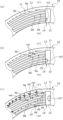
도 4는 정지 밀봉환의 슬라이딩면에 있어서의 요부(要部) 확대도이다.
도 5의 (a)~(c)는 상대 회전 초기에 액체 유도홈부의 내경측으로부터 흡입된 피밀봉 액체가 슬라이딩면 사이로 유출되는 동작을 설명하는 개략도이다.
도 6은 상대 회전 초기에 액체 유도홈부의 내경측으로부터 흡입된 피밀봉 액체가 슬라이딩면 사이로 유출되는 동작을 설명하는 개략도이다.
도 7은 본 발명의 실시예 2에 있어서의 정지 밀봉환의 슬라이딩면을 축방향으로부터 본 도면이다.
도 8은 본 발명의 실시예 3에 있어서의 정지 밀봉환의 슬라이딩면을 축방향으로부터 본 도면이다.
도 9의 (a)는 본 발명의 변형예 1을 나타내는 설명도, (b)는 본 발명의 변형예 2를 나타내는 설명도이다.
도 10은 본 발명의 실시예 4에 있어서의 정지 밀봉환의 슬라이딩면을 축방향으로부터 본 도면이다.1 is a longitudinal cross-sectional view showing an example of a mechanical seal in Example 1 of the present invention.
Fig. 2 is a view of the sliding surface of the stationary seal ring viewed from the axial direction.
Figure 3 is a cross-sectional view of AA.
Fig. 4 is an enlarged view of the main portion on the sliding surface of the stationary seal ring.
5(a) to 5(c) are schematic diagrams illustrating the operation in which the liquid to be sealed, sucked from the inner diameter side of the liquid guide groove portion, flows out between the sliding surfaces at the beginning of relative rotation.
Figure 6 is a schematic diagram illustrating the operation in which the liquid to be sealed, sucked from the inner diameter side of the liquid guide groove portion at the beginning of relative rotation, flows out between the sliding surfaces.
Fig. 7 is a view of the sliding surface of the stationary seal ring in Example 2 of the present invention as seen from the axial direction.
Fig. 8 is a view of the sliding surface of the stationary seal ring in Example 3 of the present invention as seen from the axial direction.
Figure 9 (a) is an explanatory diagram showing a modification example 1 of the present invention, and (b) is an explanatory diagram showing a modification example 2 of the present invention.
Fig. 10 is a view showing the sliding surface of the stationary seal ring in Example 4 of the present invention as seen from the axial direction.
본 발명에 따른 슬라이딩 부품을 실시하기 위한 형태를 실시예에 기초하여 이하에 설명한다.A mode for implementing the sliding part according to the present invention will be described below based on examples.
실시예 1Example 1
실시예 1에 따른 슬라이딩 부품에 대해, 도 1 내지 도 6을 참조하여 설명한다. 또한, 본 실시예에 있어서는, 슬라이딩 부품이 메커니컬 시일인 형태를 예로 들어 설명한다. 또한, 메커니컬 시일을 구성하는 슬라이딩 부품의 외경측을 피밀봉 유체측으로서의 피밀봉 액체측(고압측), 내경측을 누설측으로서의 대기측(저압측)으로 하여 설명한다. 또한, 설명의 편의상, 도면에 있어서, 슬라이딩면에 형성되는 홈 등에 도트를 부여하는 경우도 있다.The sliding part according to Example 1 will be described with reference to FIGS. 1 to 6. In addition, in this embodiment, an example in which the sliding part is a mechanical seal will be described. In addition, the explanation will be made with the outer diameter side of the sliding part constituting the mechanical seal as the liquid side to be sealed (high pressure side) as the fluid side to be sealed, and the inner diameter side as the atmospheric side (low pressure side) as the leakage side. Additionally, for convenience of explanation, in the drawings, dots may be given to grooves, etc. formed on the sliding surface.
도 1에 나타나는 일반 산업 기계용의 메커니컬 시일은, 슬라이딩면의 외경측으로부터 내경측을 향하여 누설되려고 하는 피밀봉 액체(F)를 밀봉하는 인사이드형의 시일이며, 회전축(1)에 슬리브(2)를 통하여 회전축(1)과 일체적으로 회전 가능한 상태로 마련된 원환상의 슬라이딩 부품인 회전 밀봉환(20)과, 피장착 기기의 하우징(4)에 고정된 시일 커버(5)에 비회전 상태 또한 축방향 이동 가능한 상태로 마련된 슬라이딩 부품으로서의 원환상의 정지 밀봉환(10)으로 주로 구성되고, 벨로우즈(7)에 의해 정지 밀봉환(10)이 축방향으로 부세(付勢)됨으로써, 정지 밀봉환(10)의 슬라이딩면(11)과 회전 밀봉환(20)의 슬라이딩면(21)이 서로 밀접 슬라이딩하도록 되어 있다. 또한, 회전 밀봉환(20)의 슬라이딩면(21)은 평탄면으로 되어 있고, 이 평탄면에는 오목부가 마련되어 있지 않다.The mechanical seal for general industrial machinery shown in FIG. 1 is an inside-type seal that seals the liquid (F) to be sealed that is about to leak from the outer diameter side of the sliding surface toward the inner diameter side, and is attached to the rotating shaft (1) with a sleeve (2). The
정지 밀봉환(10) 및 회전 밀봉환(20)은, 대표적으로는 SiC(경질 재료)끼리 또는 SiC(경질 재료)와 카본(연질 재료)의 조합으로 형성되지만, 이에 한정하지 않고, 슬라이딩 재료는 메커니컬 시일용 슬라이딩 재료로서 사용되고 있는 것이라면 적용 가능하다. 또한, SiC로서는, 보론, 알루미늄, 카본 등을 소결 조제로 한 소결체를 비롯하여, 성분, 조성이 상이한 2종류 이상의 상으로 이루어지는 재료, 예를 들면, 흑연 입자가 분산된 SiC, SiC와 Si로 이루어지는 반응 소결 SiC, SiC-TiC, SiC-TiN 등이 있고, 카본으로서는, 탄소질과 흑연질이 혼합된 카본을 비롯하여, 수지 성형 카본, 소결 카본 등을 이용할 수 있다. 또한, 상기 슬라이딩 재료 이외로는, 금속 재료, 수지 재료, 표면 개질 재료(코팅 재료), 복합 재료 등도 적용 가능하다.The
도 2에 나타나는 바와 같이, 정지 밀봉환(10)에 대하여 회전 밀봉환(20)이 화살표로 나타내는 바와 같이 상대 슬라이딩하도록 되어 있고, 정지 밀봉환(10)의 슬라이딩면(11)에는 복수의 동압 발생 기구(14)가 정지 밀봉환(10)의 둘레 방향으로 균등하게 배설(配設)되어 있다. 슬라이딩면(11)의 동압 발생 기구(14) 이외의 부분은 평탄면을 이루는 랜드(12)로 되어 있다.As shown in FIG. 2, the
다음으로, 동압 발생 기구(14)의 개략에 대해서 도 2~도 4에 기초하여 설명한다. 또한, 이하, 정지 밀봉환(10) 및 회전 밀봉환(20)이 상대적으로 회전했을 때에, 도 4의 지면(紙面) 좌측을 후술하는 스파이럴홈(9A, 9B) 내를 흐르는 피밀봉 액체(F)의 하류측으로 하고, 도 4의 지면 우측을 스파이럴홈(9A, 9B) 내를 흐르는 피밀봉 액체(F)의 상류측으로 하여 설명한다.Next, the outline of the dynamic
동압 발생 기구(14)는, 대기측과 연통하고 외경 방향으로 연장되는 심구부로서의 액체 유도홈부(15)와, 액체 유도홈부(15)로부터 하류측을 향하여 둘레 방향으로 병렬되어 연장되는 천구부로서의 복수의 스파이럴홈(9A)과, 스파이럴홈(9A)의 내경측에 있어서 대기측과 연통하고 스파이럴홈(9A)과 둘레 방향으로 병렬되어 연장되는, 스파이럴홈(9A)과는 독립된 서브 천구부로서의 복수의 스파이럴홈(9B)을 구비하고 있다. 또한, 본 실시예 1의 액체 유도홈부(15)는, 정지 밀봉환(10)의 축과 직교하도록 지름 방향으로 연장되어 있다. 또한, 본 실시예 1의 4개의 스파이럴홈(9A)과 5개의 스파이럴홈(9B)은, 액체 유도홈부(15)로부터 하류측을 향하여 액체 유도홈부(15)의 지름 방향의 폭과 동일한 폭으로 정지 밀봉환(10)과 동심 형상으로 둘레 방향으로 연장되는 띠 형상의 영역 내에 있어서 등간격으로 병렬되어 있다. 또한, 액체 유도홈부(15)와 스파이럴홈(9A)은 연통하고 있고, 연통 부분에는 깊이 방향의 단차(18)가 형성되어 있다.The dynamic
또한, 스파이럴홈(9A, 9B)은, 연설 방향 단부, 즉 하류측의 단부에 끝이 가늘어지는 형상을 이루는 벽부(9a)가 형성되어 있다. 또한, 벽부(9a)는, 끝이 가늘어지는 형상에 한정되는 것은 아니고, 예를 들면 회전 방향에 대하여 직교 또는 경사져 있어도 좋고, 계단 형상으로 형성되어 있어도 좋다.Additionally, the
또한, 액체 유도홈부(15)의 깊이 치수(L10)는, 스파이럴홈(9A)의 깊이 치수(L20)보다도 깊게 되어 있다(L10>L20). 구체적으로는, 본 실시예 1에 있어서의 액체 유도홈부(15)의 깊이 치수(L10)는, 100μm로 형성되어 있고, 스파이럴홈(9A)의 깊이 치수(L20)는, 5μm로 형성되어 있다. 즉, 액체 유도홈부(15)와 스파이럴홈(9A) 사이에는, 액체 유도홈부(15)에 있어서의 하류측의 측면과 스파이럴홈(9A)의 바닥면에 의해 깊이 방향의 단차(18)가 형성되어 있다. 또한, 액체 유도홈부(15)의 깊이 치수가 스파이럴홈(9A)의 깊이 치수보다도 깊게 형성되어 있으면, 액체 유도홈부(15) 및 스파이럴홈(9A)의 깊이 치수는 자유롭게 변경할 수 있고, 바람직하게는 치수(L10)는 치수(L20)의 5배 이상이다. 또한, 설명의 편의상, 도시를 생략하지만, 스파이럴홈(9B)은, 스파이럴홈(9A)과 동일한 깊이 치수(L20)(5μm)로 형성되어 있다.Additionally, the depth L10 of the
또한, 스파이럴홈(9A, 9B)의 바닥면은 평탄면을 이루어 랜드(12)에 평행하게 형성되어 있지만, 평탄면에 미세 오목부를 마련하는 것이나 랜드(12)에 대하여 경사지게 형성하는 것도 무방하다. 또한, 스파이럴홈(9A, 9B)의 둘레 방향으로 연장되는 2개의 원호 형상의 면은 각각 스파이럴홈(9A, 9B)의 바닥면과 직교하고 있다. 또한, 액체 유도홈부(15)의 바닥면은 평탄면을 이루어 랜드(12)에 평행하게 형성되어 있지만, 평탄면에 미세 오목부를 마련하는 것이나 랜드(12)에 대하여 경사지게 형성하는 것도 무방하다. 또한, 액체 유도홈부(15)의 지름 방향으로 연장되는 2개의 평면은 각각 액체 유도홈부(15)의 바닥면과 직교하고 있다.In addition, the bottom surfaces of the
이어서, 정지 밀봉환(10)과 회전 밀봉환(20)의 상대 회전시의 동작에 대하여 설명한다. 우선, 회전 밀봉환(20)이 회전하고 있지 않는 일반 산업 기계의 비가동시에는, 슬라이딩면(11, 21) 사이에는 슬라이딩면(11, 21)보다도 외경측의 피밀봉 액체(F)가 모세관 현상에 의해 근소하게 진입하고 있음과 동시에, 동압 발생 기구(14)에는 일반 산업 기계의 정지시에 남아 있었던 피밀봉 액체(F)와 슬라이딩면(11, 21)보다도 내경측으로부터 진입한 대기가 혼재된 상태로 되어 있다. 또한, 피밀봉 액체(F)는 기체와 비교하여 점도가 높기 때문에, 일반 산업 기계의 정지시에 동압 발생 기구(14)로부터 저압측으로 누출되는 양은 적다.Next, the operation of the
일반 산업 기계의 정지시에 동압 발생 기구(14)에 피밀봉 액체(F)가 거의 남아 있지 않은 경우에는, 회전 밀봉환(20)이 정지 밀봉환(10)에 대하여 상대 회전(도 2의 검은색 화살표 참조)하면, 도 4 에 나타나는 바와 같이, 대기측의 저압측 유체(A)가 화살표(L1)로 나타내는 바와 같이 액체 유도홈부(15)로부터 도입됨과 동시에, 스파이럴홈(9A)에 의해 저압측 유체(A)가 회전 밀봉환(20)의 회전 방향으로 화살표(L2)로 나타내는 바와 같이 추종 이동하기 때문에, 스파이럴홈(9A) 내에 동압이 발생하게 된다. 또한, 화살표(L4)로 나타내는 바와 같이, 스파이럴홈(9B)의 저압측의 개구로부터도 대기측의 저압측 유체(A)가 도입되어, 스파이럴홈(9B)에 의해 저압측 유체(A)가 회전 밀봉환(20)의 회전 방향으로 화살표(L5)로 나타내는 바와 같이 추종 이동하기 때문에, 스파이럴홈(9B) 내에도 동압이 발생하게 된다.When the general industrial machine is stopped and there is almost no liquid F remaining in the dynamic
스파이럴홈(9A, 9B)의 하류측 단부인 벽부(9a) 근방이 가장 압력이 높아져, 저압측 유체(A)는 화살표(L3, L6)에 나타내는 바와 같이 벽부(9a) 근방으로부터 그 주변으로 유출된다. 또한, 스파이럴홈(9A, 9B)의 상류측을 향함에 따라 점차 압력이 낮아져 있다.The pressure becomes highest near the
또한, 정지 밀봉환(10)과 회전 밀봉환(20)의 상대 회전시에는, 슬라이딩면(11, 21) 사이에 그들의 외경측으로부터 고압의 피밀봉 액체(F)가 수시 유입되고 있어, 소위 유체 윤활을 이루도록 되어 있다. 이때, 스파이럴홈(9A, 9B) 근방의 피밀봉 액체(F)는, 전술한 바와 같이 스파이럴홈(9A, 9B)의 특히 하류측은 고압으로 되어 있기 때문에, 화살표(H1)로 나타내는 바와 같이, 랜드(12)에 위치한 채로, 스파이럴홈(9A, 9B)에는 거의 진입하지 않는다. 한편, 액체 유도홈부(15) 근방의 피밀봉 액체(F)는, 액체 유도홈부(15)가 심구부이며 또한 저압측과 연통하고 있는 점에서, 화살표(H2)에 나타내는 바와 같이, 액체 유도홈부(15)에 진입하기 쉽게 있다. 게다가, 피밀봉 액체(F)는 액체이며 표면 장력이 큰 점에서, 액체 유도홈부(15)의 측벽면을 따라 이동하여 액체 유도홈부(15)에 진입하기 쉽게 되어 있다. 또한, 설명의 편의상, 화살표(H1)는 최외경의 스파이럴홈(9A)에 대해서만 도시하고 있다.In addition, during the relative rotation of the
또한, 화살표(L3)에 나타내는 바와 같이, 저압측 유체(A)가 고압측의 스파이럴홈(9A)의 하류측 단부인 벽부(9a) 근방으로부터 그 주변으로 유출됨으로써, 저압측에 병렬 배치되는 스파이럴홈(9A)과의 사이에서 랜드(12)에 위치하고 있었던 피밀봉 액체(F)의 일부가 밀려, 고압측의 스파이럴홈(9A)의 벽부(9a)의 주변까지 병렬되어 연설되는 저압측의 스파이럴홈(9A)으로 진입하도록 되어 있다. 또한, 이러한 저압측 유체(A)에 의한 피밀봉 액체(F)의 압입은, 도 4에 나타나는 병렬하고 있는 스파이럴홈(9A, 9A) 사이에 한정되는 것은 아니고, 화살표(L3, L6)에 나타내는 바와 같이, 각 스파이럴홈(9A, 9B)의 벽부(9a)로부터 그 근방으로 유출되는 저압측 유체(A)에 의해 다른 병렬하는 스파이럴홈(9A, 9B) 사이 또는 스파이럴홈(9B, 9B) 사이에 있어서도 동일하게 행해진다.In addition, as shown by arrow L3, the low-pressure side fluid A flows out from the vicinity of the
이어서, 액체 유도홈부(15)에 흡입된 피밀봉 액체(F)가 슬라이딩면(11, 21) 사이로 유출되는 동작을 설명한다.Next, the operation in which the liquid to be sealed (F) sucked into the
동압 발생 기구(14)에 피밀봉 액체(F)가 거의 남아 있지 않은 경우에, 회전 밀봉환(20)이 정지 밀봉환(10)에 대하여 상대 회전(도 2의 검은색 화살표 참조)하면, 도 5(a)에 나타나는 바와 같이, 액체 유도홈부(15)에 진입한 피밀봉 액체(F)는, 부호(H3)에 나타내는 바와 같이, 괴상(塊狀)의 액적이 된다. 그 후, 도 5(b)에 나타나는 바와 같이, 액적이 어느 정도의 체적이 되면, 부호(H4)에 나타내는 바와 같이, 스파이럴홈(9A, 9A')의 상류측에 형성된 상대적으로 낮은 압력에 의해 스파이럴홈(9A, 9A')에 인입된다. 동시에, 새롭게 액체 유도홈부(15)에 피밀봉 액체(F)가 진입하여, 액적(H3')이 된다. 이때, 액체 유도홈부(15)에는, 도 5(a)에 있어서의 상대 회전의 초기 상태보다도 많은 피밀봉 액체(F)가 진입한다.When almost no liquid F to be sealed remains in the dynamic
그 후, 도 5(c)에 나타나는 바와 같이, 스파이럴홈(9A, 9A')에 인입된 피밀봉 액체(F)는 회전 밀봉환(20)으로부터 큰 전단력을 받아, 압력이 높아지면서 스파이럴홈(9A, 9A') 내를 하류측으로 이동하여, 화살표(H5)로 나타내는 바와 같이 벽부(9a) 근방으로부터 그 주변으로 유출된다. 또한, 벽부(9a) 근방으로부터 그 주변으로 유출된 피밀봉 액체(F)의 일부는, 화살표(H6)로 나타내는 바와 같이 저압측에 병렬 배치되는 스파이럴홈(9A)과의 사이에서 랜드(12)에 위치하고 있었던 피밀봉 액체(F)의 일부와 함께 저압측의 스파이럴홈(9A)에 진입한다. 동시에, 새롭게 액체 유도홈부(15)에 피밀봉 액체(F)가 진입하여, 액적(H3")이 됨과 동시에, 액적(H3')이 부호(H4')로 나타내는 바와 같이, 각 스파이럴홈(9A)에 인입된다. 또한, 스파이럴홈(9B)의 개구로부터도 피밀봉 액체(F)가 진입하여, 액적(H7)이 된다. 또한, 스파이럴홈(9B)의 개구측으로부터 진입하는 피밀봉 액체(F)는 소량이기 때문에, 액적(H7)은 액적(H4)과 비교하면 작은 덩어리이다.Afterwards, as shown in Figure 5(c), the liquid to be sealed (F) drawn into the
도 6에 나타나는 바와 같이, 스파이럴홈(9A, 9A')에 인입된 피밀봉 액체(F)는 스파이럴홈(9A, 9A') 내를 하류측으로 이동하고, 화살표(H5')로 나타내는 바와 같이 벽부(9a) 근방으로부터 그 주변으로 유출된다. 또한, 벽부(9a) 근방으로부터 그 주변으로 유출된 피밀봉 액체(F)의 일부는, 화살표(H6)로 나타내는 바와 같이 저압측에 병렬 배치되는 스파이럴홈(9A, 9A') 또는 스파이럴홈(9B)과의 사이에서 랜드(12)에 위치하고 있었던 피밀봉 액체(F)의 일부와 함께 저압측의 스파이럴홈(9A, 9A') 또는 스파이럴홈(9B)으로 진입한다. 동시에, 액체 유도홈부(15)에 피밀봉 액체(F)가 추가로 진입하여, 액적(H3"')이 됨과 동시에, 액적(H3")이 부호(H4")로 나타내는 바와 같이, 각 스파이럴홈(9A)에 인입된다.As shown in FIG. 6, the liquid to be sealed (F) drawn into the
그 후, 도 6에 나타나는 상태보다도 액체 유도홈부(15)에 진입하는 피밀봉 액체(F)의 양이 증가하여, 각 스파이럴홈(9A)으로부터 연속적으로 피밀봉 액체(F)가 슬라이딩면(11, 21) 사이로 유출되는 정상(定常) 상태가 된다. 정상 상태에서는, 슬라이딩면(11, 21) 사이에 그들의 외경측이나 스파이럴홈(9A, 9B)으로부터 고압의 피밀봉 액체(F)가 수시 유입되고 있어, 전술한 바와 같이 유체 윤활로 되어 있다. 또한, 도 5(a), (b), (c)를 거쳐 정상 상태가 될 때까지는 과도적인 짧은 시간이다. 또한, 일반 산업 기계의 정지시에 동압 발생 기구(14)에 피밀봉 액체(F)가 남아 있는 경우에는, 동압 발생 기구(14)에 피밀봉 액체(F)가 잔존하고 있는 양에 따라, 도 5(a)의 상태, 도 5(b)의 상태, 도 5(c)의 상태, 정상 상태 중 어느 것으로부터 동작이 개시되는 것이 된다.After that, the amount of the liquid F to be sealed entering the
여기에서, 액체 유도홈부(15)가 심구부이며 또한 저압측과 연통하고 있는 점에서, 화살표(H5)로 나타내는 피밀봉 액체(F)는, 인접하는 액체 유도홈부(15) 내로 인입되기 쉽게 되어 있고, 슬라이딩면(11, 21) 사이의 피밀봉 액체(F)의 양이 안정되어, 높은 윤활성을 유지할 수 있도록 되어 있다. 또한, 스파이럴홈(9B)은 개구측까지 동일한 깊이의 얕은 홈이기 때문에, 정상 상태에 있어서도, 액체 유도홈부(15)에 비하여 스파이럴홈(9B)의 개구측으로부터 진입하는 피밀봉 액체(F)의 양이 크게 증가하는 일은 없다. 또한, 고체에 대한 계면 장력은 기체보다도 액체 쪽이 크기 때문에, 슬라이딩면(11, 21) 사이에는 피밀봉 액체(F)가 보지되기 쉽고 대기는 정지 밀봉환(10), 회전 밀봉환(20)보다도 내경측으로 배출되기 쉽다.Here, since the
이상과 같이, 정지 밀봉환(10)과 회전 밀봉환(20)의 상대 회전시에 있어서, 스파이럴홈(9A)에는, 액체 유도홈부(15)에 진입한 피밀봉 액체(F)를 인입하여 동압이 발생하고 있다. 액체 유도홈부(15)는 홈의 깊이가 깊고 용적이 크기 때문에, 슬라이딩면(11)의 저압측까지 피밀봉 액체(F)를 공급해도, 피밀봉 액체(F)를 회수하여 스파이럴홈(9A)에 의해 슬라이딩면(11, 21) 사이로 되돌릴 수 있기 때문에, 슬라이딩면(11)의 넓은 면적에 있어서 윤활성을 향상시킬 수 있다. 또한, 슬라이딩면(11, 21)보다도 내경측의 저압측과 연통하는 액체 유도홈부(15)에 의해 피밀봉 액체(F)를 회수하여, 회수한 피밀봉 액체(F)를 스파이럴홈(9A)으로부터 슬라이딩면(11, 21) 사이로 유출시켜 일부를 고압측으로 되돌리기 때문에, 저압측으로 누설되는 피밀봉 액체(F)가 적다. 또한, 스파이럴홈(9A)의 하류측 단부가 끝이 가늘어지는 형상임으로써, 스파이럴홈(9A)의 벽부(9a)로부터 슬라이딩면(11, 21) 사이로 되돌려지는 피밀봉 액체(F)의 유량이 확보되기 쉬워지기 때문에, 동압을 안정적으로 발생시킬 수 있다. 게다가, 병렬하는 복수의 스파이럴홈(9A)에 있어서, 고압측의 스파이럴홈(9A)의 벽부(9a) 근방으로부터 주변으로 유출되는 피밀봉 액체(F)를 저압측에 병렬 배치되는 스파이럴홈(9A)에 의해 포집할 수 있기 때문에, 윤활성을 보다 향상시킴과 동시에, 저압측으로 누설되는 피밀봉 액체(F)를 보다 적게 할 수 있다.As described above, during the relative rotation of the
또한, 액체 유도홈부(15)와 연통하는 복수의 스파이럴홈(9A)의 벽부(9a) 근방으로부터 주변으로 유출되는 피밀봉 액체(F)를 저압측의 스파이럴홈(9B)에 의해 추가로 포집할 수 있기 때문에, 저압측으로 누설되는 피밀봉 액체(F)를 더욱 적게 할 수 있다. 또한, 액체 유도홈부(15)와 연통하지 않는 스파이럴홈(9B)에 대한 피밀봉 액체(F)의 도입량을 늘릴 수 있기 때문에, 슬라이딩면(11)에 있어서의 동압 발생 기구(14)의 유효 범위를 넓힐 수 있다.In addition, the liquid (F) to be sealed flowing out to the surroundings from the vicinity of the wall portion (9a) of the plurality of spiral grooves (9A) communicating with the liquid guide groove portion (15) can be additionally collected by the spiral groove (9B) on the low pressure side. Therefore, the liquid to be sealed (F) leaking to the low pressure side can be further reduced. In addition, since the introduction amount of the liquid (F) to be sealed into the spiral groove (9B) that does not communicate with the liquid guide groove portion (15) can be increased, the effective range of the dynamic pressure generating mechanism (14) in the sliding surface (11) can be increased. can be expanded.
또한, 많은 양의 피밀봉 액체(F)가 액체 유도홈부(15)에 보지되기 때문에, 스파이럴홈(9A) 내로 인입되는 피밀봉 액체(F)의 양을 충분히 확보할 수 있음과 동시에, 액체 유도홈부(15)에 보지되는 피밀봉 액체(F)의 양이 짧은 시간에 있어서 증감해도 스파이럴홈(9A) 내로 인입되는 피밀봉 액체(F)의 양을 거의 일정하게 할 수 있어, 슬라이딩면(11, 21)이 빈(貧)윤활이 되는 것을 회피할 수 있다. 또한, 액체 유도홈부(15)가 저압측과 연통하고 있기 때문에, 슬라이딩면(11, 21) 사이의 피밀봉 액체(F)의 압력에 비하여 액체 유도홈부(15) 내의 압력이 낮아져 있어, 액체 유도홈부(15)의 근방의 피밀봉 액체(F)는 액체 유도홈부(15) 내로 인입되기 쉽게 되어 있다.In addition, since a large amount of the liquid to be sealed (F) is held in the liquid
또한, 스파이럴홈(9A, 9B)은, 고압측을 향하여 연장되어 있기 때문에, 스파이럴홈(9A, 9B)의 벽부(9a)에 있어서의 동압에 의한 고압부를 고압측에 가깝게 하여 배치할 수 있고, 특히 스파이럴홈(9A)에 있어서는, 액체 유도홈부(15)를 통한 흡입 능력을 높일 수 있다. 또한, 스파이럴홈(9A, 9B)의 벽부(9a)로부터 피밀봉 액체(F)를 슬라이딩면(11, 21) 사이의 고압측에 가깝게 한 위치로 되돌릴 수 있기 때문에, 피밀봉 액체(F)의 누설을 적게 할 수 있다.In addition, since the
또한, 스파이럴홈(9A, 9B)은, 둘레 방향으로 만곡하고 있기 때문에, 스파이럴홈(9A, 9B)의 곡률에 따라 동압을 조정할 수 있다. 또한, 스파이럴홈(9A, 9B)의 벽부(9a)까지의 거리를 길게 할 수 있기 때문에, 큰 압력을 얻을 수 있다. 또한, 스파이럴홈(9A, 9B)은, 상이한 곡률로 형성되어 있어도 좋다.Additionally, since the
또한, 액체 유도홈부(15)는, 지름 방향으로 연장되어 있다. 구체적으로는, 액체 유도홈부(15)는, 정지 밀봉환(10)의 중심축과 직교하는 방향으로 연장되어 있기 때문에, 둘레 방향의 폭을 짧게 하여 정지 밀봉환(10)의 둘레 방향으로 많이 배치할 수 있기 때문에 설계 자유도가 높다. 또한, 액체 유도홈부(15)는, 정지 밀봉환(10)의 중심축과 직교하는 방향에 한정되지 않고, 정지 밀봉환(10)의 중심축과 직교하는 위치로부터 경사져 있어도 좋지만, 45도 미만의 경사인 것이 바람직하다. 또한, 액체 유도홈부(15)의 형상은 원호 형상 등 자유롭게 변경할 수 있다.Additionally, the liquid
또한, 스파이럴홈(9A)과 액체 유도홈부(15)의 연통 부분에는, 액체 유도홈부(15)에 있어서의 하류측의 측면과 스파이럴홈(9A)의 바닥면에 의해 단차(18)가 형성되어 있기 때문에, 동압의 영향을 직접적으로 받지 않고 피밀봉 액체(F)를 액체 유도홈부(15)에 보지할 수 있다.In addition, in the communicating portion of the
또한, 스파이럴홈(9A)은, 각각 지름 방향의 전폭에 걸쳐 액체 유도홈부(15)와 연통하고 있기 때문에, 스파이럴홈(9A)의 액체 유도홈부(15)로의 개구 영역을 확보할 수 있어, 액체 유도홈부(15)에 보지된 피밀봉 액체(F)를 효율적으로 빨아올릴 수 있다.In addition, since each of the spiral grooves (9A) communicates with the liquid guide groove portion (15) over the entire width in the radial direction, the opening area of the spiral groove (9A) to the liquid guide groove portion (15) can be secured, thereby allowing liquid The liquid to be sealed (F) held in the
또한, 액체 유도홈부(15)는, 정지 밀봉환(10)의 내경측과 연통하고 있다. 즉, 슬라이딩 부품은, 인사이드형의 메커니컬 시일이며, 정지 밀봉환(10) 및 회전 밀봉환(20)의 상대 회전시에는, 원심력에 의해 스파이럴홈(9A) 내의 피밀봉 액체(F)를 고압측으로 되돌릴 수 있음과 동시에, 피밀봉 액체(F)의 슬라이딩면(11, 21)보다도 내경측의 저압측으로의 누설을 저감할 수 있다.Additionally, the liquid
또한, 정지 밀봉환(10)에 동압 발생 기구(14)가 마련되어 있기 때문에, 정지 밀봉환(10) 및 회전 밀봉환(20)의 상대 회전시에, 액체 유도홈부(15) 내를 대기압에 가까운 상태로 유지하기 쉽다.In addition, since the dynamic
또한, 본 실시예 1에서는, 액체 유도홈부(15)와 스파이럴홈(9A)의 연통 부분에 단차가 마련되어 있지 않아도 좋고, 예를 들면, 액체 유도홈부(15)와 스파이럴홈(9A)이 경사면에서 연통하고 있어도 좋다. 이 경우, 예를 들면, 5μm 이하의 깊이 치수를 갖는 부분이 스파이럴홈(9A)이 되고, 5μm보다도 깊은 부분을 액체 유도홈부(15)로 할 수 있다.Additionally, in this
또한, 스파이럴홈(9A, 9B)은, 액체 유도홈부(15)로부터 하류측을 향하여 액체 유도홈부(15)의 지름 방향의 폭과 동일한 폭으로 정지 밀봉환(10)과 동심 형상으로 둘레 방향으로 연장되는 띠 형상의 영역 내에 형성되는 형태에 한정되지 않고, 예를 들면, 원호 형상 또는 사다리꼴 형상 등 다른 형상의 영역 내에 형성되어 있어도 좋다. 또한, 스파이럴홈(9A, 9B)은, 병렬로 연장되는 것이면 등간격으로 형성되지 않아도 좋다. 또한, 스파이럴홈(9A, 9B)은, 액체 유도홈부(15)로부터 직선 형상으로 연설되도록 되어 있어도 좋고, 사행(蛇行)하여 연설되어 있어도 좋다. 또한, 스파이럴홈(9B)은 마련하지 않아도 좋다.In addition, the
실시예 2Example 2
다음으로, 실시예 2에 따른 슬라이딩 부품에 대해, 도 7을 참조하여 설명한다. 또한, 상기 실시예 1과 동일한 구성, 중복하는 구성의 설명은 생략한다.Next, the sliding part according to Example 2 will be described with reference to FIG. 7. Additionally, descriptions of the same or overlapping configurations as those of
도 7에 나타나는 바와 같이, 정지 밀봉환(101)에 마련되는 동압 발생 기구(141)는, 액체 유도홈부(115)와, 스파이럴홈(109A, 109B)과, 액체 유도홈부(115)로부터 하류측을 향하여 둘레 방향으로 병렬되어 연장되는 천구부로서의 복수의 스파이럴홈(109C)과, 스파이럴홈(109C)의 내경측에 있어서 대기측과 연통하고 스파이럴홈(109C)과 둘레 방향으로 병렬되어 연장되는 스파이럴홈(109C)과는 독립된 서브 천구부로서의 복수의 스파이럴홈(109D)을 구비하고 있다. 또한, 스파이럴홈(109C, 109D)은, 스파이럴홈(109A, 109B)과 동일한 5μm의 깊이 치수로 형성되어 있다.As shown in FIG. 7, the dynamic
도 7의 지면 반시계 방향으로 회전 밀봉환(20)이 회전하는 경우에는, 저압측 유체(A)가 화살표(L1, L2, L3 및 L4, L5, L6)의 순으로 이동하여 스파이럴홈(109A, 109B) 내에 동압이 발생한다. 또한, 도 7의 지면 시계 방향으로 회전 밀봉환(20)이 회전하는 경우에는, 저압측 유체(A)가 화살표(L1, L2', L3' 및 L4', L5', L6')의 순으로 이동하여 스파이럴홈(109C, 109D) 내에 동압이 발생한다.When the
이와 같이, 액체 유도홈부(115)로부터 둘레 방향 양측에 스파이럴홈(109A, 109C)이 연설되어 있기 때문에, 스파이럴홈(109A, 109C)의 어느 한쪽을 동압 발생용의 천구부로서 이용할 수 있기 때문에, 정지 밀봉환(101)과 회전 밀봉환(20)의 상대 회전 방향과 상관없이 사용할 수 있다. 또한, 스파이럴홈(109B, 109D)에 대해서도, 어느 한쪽을 동압 발생용의 서브 천구부로서 이용할 수 있기 때문에, 정지 밀봉환(101)과 회전 밀봉환(20)의 상대 회전 방향과 상관없이 사용할 수 있다.In this way, since the
또한, 동압 발생 기구(141)에 있어서의 하류측 단부에 형성되는 스파이럴홈(109B)은, 인접하는 동압 발생 기구(141')에 있어서의 상류측 단부에 형성되는 스파이럴홈(109D)과 둘레 방향으로 인접하고 있다. 이에 의하면, 동압 발생 기구(141)에 있어서의 하류측 단부에 형성되는 스파이럴홈(109B)의 벽부(9a) 근방으로부터 그 주변으로 유출되어, 내경측으로 이동하려고 하는 피밀봉 액체(F)가 인접하는 동압 발생 기구(141')에 있어서의 상류측 단부에 형성되는 스파이럴홈(109D)으로 흡입되기 때문에, 피밀봉 액체(F)의 저압측으로의 누설을 저감할 수 있다.In addition, the
또한, 본 실시예 2에서는, 스파이럴홈(109A, 109B) 및 스파이럴홈(109C, 109D)이 동일한 깊이 치수인 경우를 예시했지만, 상이한 깊이 치수로 형성되어 있어도 좋다. 또한, 양자는 둘레 방향 길이, 지름 방향폭에 대해서도 동일해도 상이해도 좋다.Additionally, in this second embodiment, the case where the
또한, 동압 발생 기구(141)에 있어서의 하류측 단부에 형성되는 스파이럴홈(109B)과 인접하는 동압 발생 기구(141')에 있어서의 상류측 단부에 형성되는 스파이럴홈(109D)을 둘레 방향으로 긴 거리 이간시켜, 슬라이딩면(11, 21) 사이를 이간시키는 압력을 보다 높이도록 해도 좋다.In addition, the
실시예 3Example 3
다음으로, 실시예 3에 따른 슬라이딩 부품에 대해, 도 8을 참조하여 설명한다. 또한, 상기 실시예 2와 동일한 구성, 중복하는 구성의 설명은 생략한다.Next, the sliding part according to Example 3 will be described with reference to FIG. 8. In addition, descriptions of the same or overlapping configurations as those of
도 8에 나타나는 바와 같이, 정지 밀봉환(102)에는, 동압 발생 기구(141)와, 특정 동압 발생 기구(16)가 복수 형성되어 있다. 특정 동압 발생 기구(16)는, 고압측과 연통하는 액체 유도홈부(161)와, 액체 유도홈부(161)의 외경측 단부로부터 하류측을 향하여 정지 밀봉환(102)과 동심 형상으로 둘레 방향으로 연장되는 레일리 스텝(17A)과, 액체 유도홈부(161)의 외경측 단부로부터 상류측을 향하여 정지 밀봉환(102)과 동심 형상으로 둘레 방향으로 연장되는 역레일리 스텝(17B)을 구비하고 있다. 액체 유도홈부(161)와 액체 유도홈부(115)는, 둘레 방향으로 대응하는 위치에 형성되어 있다. 즉, 액체 유도홈부(161)와 액체 유도홈부(115)는, 지름 방향을 따라 형성되어 있다. 또한, 액체 유도홈부(161)는, 특정 동압 발생 기구(16)의 심구부로서 기능하고 있고, 레일리 스텝(17A) 및 역레일리 스텝(17B)은, 특정 동압 발생 기구(16)의 천구부로서 기능하고 있다.As shown in Fig. 8, a plurality of dynamic
동압 발생 기구(141)의 스파이럴홈(109A, 109B) 및 스파이럴홈(109C, 109D)은, 특정 동압 발생 기구(16)의 레일리 스텝(17A) 및 역레일리 스텝(17B)보다도 둘레 방향으로 넓은 영역 내에 형성되어 있다. 또한, 레일리 스텝(17A) 및 역레일리 스텝(17B)은, 스파이럴홈(109A, 109B) 및 스파이럴홈(109C, 109D)과 동일한 5μm의 깊이 치수로 형성되어 있다. 또한, 동압 발생 기구(141)의 용적은, 특정 동압 발생 기구(16)의 용적보다도 크게 형성되어 있다.The
도 8의 지면 반시계 방향으로 회전 밀봉환(20)이 회전하는 경우에는, 피밀봉 액체(F)가 화살표(L11, L12, L13)의 순으로 이동하여 레일리 스텝(17A) 내에 동압이 발생한다. 또한, 도 8의 지면 시계 방향으로 회전 밀봉환(20)이 회전하는 경우에는, 피밀봉 액체(F)가 화살표(L11, L12', L13')의 순으로 이동하여 역레일리 스텝(17B) 내에 동압이 발생한다. 이와 같이, 정지 밀봉환(102)과 회전 밀봉환(20)의 상대 회전 방향과 상관없이 특정 동압 발생 기구(16) 내에 동압을 발생시킬 수 있다.When the
또한, 특정 동압 발생 기구(16)에서 발생하는 동압에 의해 슬라이딩면(11, 21) 사이를 이간시켜 적당한 액막을 생성하면서, 슬라이딩면(11)으로부터 저압측으로 누설되려고 하는 피밀봉 액체(F)를 동압 발생 기구(141)에 의해 회수할 수 있다.In addition, the dynamic pressure generated by the specific dynamic
또한, 액체 유도홈부(161)와 액체 유도홈부(115)는, 지름 방향을 따라 형성되어 있기 때문에, 슬라이딩면(11, 21) 사이에 있어서 액체 유도홈부(161)로부터 저압측으로 누설되려고 하는 피밀봉 액체(F)가 액체 유도홈부(115)로 도입되기 쉬워지기 때문에, 피밀봉 액체(F)의 저압측으로의 누설을 효율 좋게 저감할 수 있다.In addition, since the liquid
또한, 동압 발생 기구(141)의 용적이 특정 동압 발생 기구(16)의 용적보다도 크기 때문에, 동압 발생 기구(141)의 스파이럴홈(109A, 109B) 및 스파이럴홈(109C, 109D)의 흡입력을 크게 하여, 저압측의 동압 발생 기구(141)와 고압측의 특정 동압 발생 기구(16)의 동압 밸런스를 조정할 수 있다.In addition, since the volume of the dynamic
또한, 스파이럴홈(109A, 109B) 및 스파이럴홈(109C, 109D)의 둘레 방향의 길이는, 레일리 스텝(17A) 및 역레일리 스텝(17B)과 동일한 길이, 또는 레일리 스텝(17A) 및 역레일리 스텝(17B)보다도 짧게 형성되어 있어도 좋다. 또한, 레일리 스텝(17A) 및 역레일리 스텝(17B)은, 스파이럴홈(109A, 109B) 및 스파이럴홈(109C, 109D)과 상이한 깊이 치수로 형성되어 있어도 좋다. 또한, 레일리 스텝(17A) 및 역레일리 스텝(17B)의 지름 방향의 폭은, 스파이럴홈(109A, 109B) 및 스파이럴홈(109C, 109D)의 지름 방향의 폭과 동일하게 형성되어도 좋고, 스파이럴홈(109A, 109B) 및 스파이럴홈(109C, 109D)의 지름 방향의 폭보다도 큰 폭 또는 소폭으로 형성되어 있어도 좋다. 바람직하게는, 동압 발생 기구(141)의 용적이 특정 동압 발생 기구(16)의 용적보다도 크게 형성되어 있으면 좋다.In addition, the circumferential length of the
이어서, 특정 동압 발생 기구의 변형예를 설명한다. 도 9(a)에 나타내는 바와 같이, 변형예 1의 특정 동압 발생 기구는, 슬라이딩면(11)을 직교하는 방향으로부터 보아 원형을 이루는 오목 형상의 딤플(30)이다. 또한, 딤플(30)의 형상, 수량, 배치 등은 자유롭게 변경할 수 있다.Next, a modified example of a specific dynamic pressure generating mechanism will be described. As shown in Fig. 9(a), the specific dynamic pressure generating mechanism of
또한, 도 9(b)에 나타내는 바와 같이, 변형예 2의 특정 동압 발생 기구는, 지름 방향을 향하여 경사지면서 원호 형상으로 연장되는 원호홈(31, 32)이다. 구체적으로는, 원호홈(31, 32)은 외경측의 단부가 고압측과 연통하고 있고, 원호홈(31)은, 스파이럴홈(109A, 109B)의 외경측에 복수 배설되어 있으며, 원호홈(32)은, 스파이럴홈(109C, 109D)의 외경측에 복수 배설되어 있다.Additionally, as shown in Fig. 9(b), the specific dynamic pressure generating mechanism of
또한, 원호홈(31)은, 회전 밀봉환(20)이 도 9(b)의 지면 반시계 방향으로 회전했을 때에 내경측을 향하여 피밀봉 액체(F)가 이동하는 형상으로 되어 있으며, 원호홈(32)은, 회전 밀봉환(20)이 도 9(b)의 지면 시계 방향으로 회전했을 때에 내경측을 향하여 피밀봉 액체(F)가 이동하는 형상으로 되어 있다. 회전 밀봉환(20)이 반시계 방향으로 회전했을 때에는 원호홈(31)의 내경측의 압력이 높아지고, 시계 방향으로 회전했을 때에는 원호홈(32)의 내경측의 압력이 높아지기 때문에, 슬라이딩면(11, 21)을 이간시켜 적당한 액막을 생성할 수 있도록 되어 있다. 또한, 원호홈(31, 32)의 형상, 수량, 배치 등은 자유롭게 변경할 수 있다.In addition, the
실시예 4Example 4
다음으로, 실시예 4에 따른 슬라이딩 부품에 대해, 도 10을 참조하여 설명한다. 또한, 상기 실시예 3과 동일한 구성, 중복하는 구성의 설명은 생략한다.Next, the sliding part according to Example 4 will be described with reference to FIG. 10. Additionally, descriptions of the same or overlapping configurations as those of Embodiment 3 above will be omitted.
도 10에 나타나는 메커니컬 시일은, 슬라이딩면의 내경측으로부터 외경측을 향하여 누설되려고 하는 피밀봉 액체(F)를 밀봉하는 아웃사이드형의 시일이다. 동압 발생 기구(141)는 저압측과 연통하도록 외경측에 배치되어 있고, 특정 동압 발생 기구(16)는, 고압측과 연통하도록 내경측에 배치되어 있다. 또한, 아웃사이드형의 메커니컬 시일이라도, 상기 실시예 1과 같이, 동압 발생 기구가 편회전에 대응하도록 형성되어 있어도 좋다. 또한, 상기 실시예 1과 같이, 특정 동압 발생 기구가 마련되어 있지 않아도 좋고, 특정 동압 발생 기구가 상기 실시예 3의 변형예에 나타낸 딤플이나 원호홈 등의 다른 형태로 형성되어 있어도 좋다.The mechanical seal shown in FIG. 10 is an outside type seal that seals the liquid F that is about to leak from the inner diameter side of the sliding surface toward the outer diameter side. The dynamic
이상, 본 발명의 실시예를 도면에 의해 설명했지만, 구체적인 구성은 이들 실시예에 한정되는 것은 아니고, 본 발명의 요지를 일탈하지 않는 범위에 있어서의 변경이나 추가가 있어도 본 발명에 포함된다.Although the embodiments of the present invention have been described above with reference to the drawings, the specific configuration is not limited to these embodiments, and any changes or additions that do not deviate from the gist of the present invention are included in the present invention.
예를 들면, 상기 실시예에서는, 슬라이딩 부품으로서, 일반 산업 기계용의 메커니컬 시일을 예로 설명했지만, 자동차나 워터 펌프용 등의 다른 메커니컬 시일이라도 좋다. 또한, 메커니컬 시일에 한정되지 않고, 미끄럼 베어링 등 메커니컬 시일 이외의 슬라이딩 부품이라도 좋다.For example, in the above embodiment, the sliding part was described as an example of a mechanical seal for general industrial machinery, but other mechanical seals such as those for automobiles or water pumps may also be used. Furthermore, it is not limited to mechanical seals, and sliding parts other than mechanical seals, such as sliding bearings, may be used.
또한, 상기 실시예에서는, 동압 발생 기구를 정지 밀봉환에만 마련하는 예에 대해서 설명했지만, 동압 발생 기구를 회전 밀봉환(20)에만 마련해도 좋고, 회전 밀봉환(20)과 정지 밀봉환의 양쪽에 마련해도 좋다.In addition, in the above embodiment, an example in which the dynamic pressure generating mechanism is provided only in the stationary sealing ring has been described. However, the dynamic pressure generating mechanism may be provided only in the
또한, 상기 실시예에서는, 슬라이딩 부품에 동일 형상의 동압 발생 기구가 복수 마련되는 형태를 예시했지만, 형상이 상이한 동압 발생 기구가 복수 마련되어 있어도 좋다. 또한, 동압 발생 기구의 간격이나 수량 등은 적절히 변경할 수 있다.In addition, in the above embodiment, a form in which a plurality of dynamic pressure generating mechanisms of the same shape is provided in the sliding part is exemplified, but a plurality of dynamic pressure generating mechanisms of different shapes may be provided. Additionally, the spacing or quantity of the dynamic pressure generating mechanisms can be changed appropriately.
또한, 피밀봉 유체측을 고압측, 누설측을 저압측으로 하여 설명했지만, 피밀봉 유체측이 저압측, 누설측이 고압측으로 되어 있어도 좋고, 피밀봉 유체측과 누설측이 거의 동일한 압력이라도 좋다.In addition, although the fluid side to be sealed is the high pressure side and the leak side is the low pressure side, the fluid side to be sealed may be the low pressure side and the leak side may be the high pressure side, or the fluid side to be sealed and the leak side may have substantially the same pressure.
9A; 스파이럴홈(천구부)
9B; 스파이럴홈(서브 천구부)
10; 정지 밀봉환(슬라이딩 부품)
11; 슬라이딩면
14; 동압 발생 기구
15; 액체 유도홈부(심구부)
16; 특정 동압 발생 기구
17A; 레일리 스텝(천구부)
17B; 역레일리 스텝(천구부)
18; 단차
20; 회전 밀봉환(슬라이딩 부품)
21; 슬라이딩면
109A, 109C; 스파이럴홈(천구부)
109B, 109D; 스파이럴홈(서브 천구부)
115; 액체 유도홈부(심구부)
141; 동압 발생 기구9A; Spiral groove (celestial sphere)
9B; Spiral groove (sub-celestial sphere)
10; Stationary seal ring (sliding part)
11; sliding surface
14; Dynamic pressure generating mechanism
15; Liquid guide groove (deep groove)
16; Specific dynamic pressure generating mechanism
17A; Rayleigh Step (celestial sphere)
17B; Reverse Rayleigh Step (celestial sphere)
18; step
20; Rotating seal ring (sliding part)
21; sliding surface
109A, 109C; Spiral groove (celestial sphere)
109B, 109D; Spiral groove (sub-celestial sphere)
115; Liquid guide groove (deep groove)
141; Dynamic pressure generating mechanism
Claims (7)
상기 슬라이딩 부품의 슬라이딩면에는, 누설측과 연통하는 심구부(深溝部)와, 당해 심구부와 연통하고 둘레 방향으로 병렬되어 연설(延設)되는 복수의 천구부(淺溝部)를 갖는 동압 발생 기구가 복수 마련되고,
상기 동압 발생 기구는, 누설측과 직접 연통하고 상기 천구부의 누설측에서 병렬되어 둘레 방향으로 연장되는 상기 천구부와는 독립된 복수의 서브 천구부를 갖고,
복수의 상기 천구부 중 가장 회전 방향 하류측에 위치하는 상기 천구부의 둘레 방향으로 하류측에 상기 서브 천구부가 형성되고, 상기 회전 방향 하류측에 위치하는 상기 천구부와 상기 서브 천구부는 둘레 방향으로 오버 랩 하는 슬라이딩 부품.
As an annular sliding part disposed at a relatively rotating location of a rotating machine,
The sliding surface of the sliding part has a deep groove communicating with the leakage side, and a plurality of shallow grooves communicating with the deep groove and extending in parallel in the circumferential direction. Dynamic pressure is generated. Multiple organizations are prepared,
The dynamic pressure generating mechanism has a plurality of sub-opening portions independent of the shallow opening portion, which communicate directly with the leakage side and extend in a circumferential direction in parallel on the leakage side of the shallow opening portion,
Among the plurality of celestial spheres, the sub-celestial sphere is formed on the downstream side in a circumferential direction of the celestial sphere located most downstream in the rotation direction, and the celestial sphere and the sub-celestial sphere located on the downstream side in the rotation direction extend in the circumferential direction. Sliding parts that wrap.
상기 천구부가 피밀봉 유체측을 향하여 연장되어 있는 슬라이딩 부품.
According to paragraph 1,
A sliding part in which the perforated portion extends toward the fluid to be sealed.
상기 천구부는, 둘레 방향으로 만곡하고 있는 슬라이딩 부품.
According to claim 1 or 2,
The above-mentioned celestial sphere is a sliding part curved in a circumferential direction.
상기 천구부는, 상기 심구부로부터 둘레 방향 양측으로 연장되어 있는 슬라이딩 부품.
According to claim 1 or 2,
A sliding part in which the shallow port portion extends from the deep port portion to both sides in the circumferential direction.
상기 심구부는 내경측과 연통하는 슬라이딩 부품.
According to claim 1 or 2,
A sliding part in which the deep groove part communicates with the inner diameter side.
상기 슬라이딩 부품의 슬라이딩면에는, 상기 동압 발생 기구보다도 피밀봉 유체측에 배치되고 상기 동압 발생 기구와는 독립되는 특정 동압 발생 기구를 구비하고 있는 슬라이딩 부품.
According to claim 1 or 2,
A sliding part comprising, on the sliding surface of the sliding part, a specific dynamic pressure generating mechanism that is disposed on a fluid side to be sealed rather than the dynamic pressure generating mechanism and is independent of the dynamic pressure generating mechanism.
Applications Claiming Priority (3)
| Application Number | Priority Date | Filing Date | Title |
|---|---|---|---|
| JP2019017875 | 2019-02-04 | ||
| JPJP-P-2019-017875 | 2019-02-04 | ||
| PCT/JP2020/003647 WO2020162351A1 (en) | 2019-02-04 | 2020-01-31 | Sliding component |
Publications (2)
| Publication Number | Publication Date |
|---|---|
| KR20210113364A KR20210113364A (en) | 2021-09-15 |
| KR102627904B1 true KR102627904B1 (en) | 2024-01-23 |
Family
ID=71947476
Family Applications (1)
| Application Number | Title | Priority Date | Filing Date |
|---|---|---|---|
| KR1020217025876A Active KR102627904B1 (en) | 2019-02-04 | 2020-01-31 | sliding parts |
Country Status (6)
| Country | Link |
|---|---|
| US (1) | US12498044B2 (en) |
| EP (2) | EP4345328A3 (en) |
| JP (1) | JP7387239B2 (en) |
| KR (1) | KR102627904B1 (en) |
| CN (1) | CN113439167B (en) |
| WO (1) | WO2020162351A1 (en) |
Families Citing this family (18)
| Publication number | Priority date | Publication date | Assignee | Title |
|---|---|---|---|---|
| US11125334B2 (en) * | 2016-12-21 | 2021-09-21 | Eaton Intelligent Power Limited | Hydrodynamic sealing component and assembly |
| WO2020027102A1 (en) | 2018-08-01 | 2020-02-06 | イーグル工業株式会社 | Slide component |
| CN112424514B (en) | 2018-08-24 | 2023-04-28 | 伊格尔工业股份有限公司 | Sliding member |
| CN116025714B (en) | 2018-10-01 | 2026-03-27 | 伊格尔工业股份有限公司 | sliding parts |
| CN112789434B (en) | 2018-10-24 | 2023-09-29 | 伊格尔工业股份有限公司 | sliding parts |
| EP3889474A4 (en) | 2018-11-30 | 2022-08-10 | Eagle Industry Co., Ltd. | Sliding component |
| KR102541901B1 (en) | 2018-12-21 | 2023-06-13 | 이구루코교 가부시기가이샤 | sliding parts |
| CN113260797B (en) | 2019-02-04 | 2023-02-14 | 伊格尔工业股份有限公司 | sliding parts |
| US11933405B2 (en) | 2019-02-14 | 2024-03-19 | Eagle Industry Co., Ltd. | Sliding component |
| EP4317728B1 (en) | 2019-02-21 | 2026-01-14 | Eagle Industry Co., Ltd. | Sliding components |
| JP7399966B2 (en) | 2019-07-26 | 2023-12-18 | イーグル工業株式会社 | sliding parts |
| KR20250116162A (en) | 2020-06-02 | 2025-07-31 | 이구루코교 가부시기가이샤 | Sliding component |
| US12276338B2 (en) | 2020-06-02 | 2025-04-15 | Eagle Industry Co., Ltd. | Sliding component |
| JP7608033B2 (en) | 2021-03-12 | 2025-01-06 | イーグル工業株式会社 | Sliding parts |
| EP4372253A4 (en) | 2021-07-13 | 2025-07-16 | Eagle Ind Co Ltd | SLIDING COMPONENTS |
| EP4411182A4 (en) * | 2021-09-28 | 2025-09-17 | Eagle Ind Co Ltd | Sliding component |
| KR20240093965A (en) * | 2021-11-29 | 2024-06-24 | 이구루코교 가부시기가이샤 | sliding element |
| KR20250008107A (en) * | 2022-05-19 | 2025-01-14 | 이구루코교 가부시기가이샤 | Sliding parts |
Family Cites Families (187)
| Publication number | Priority date | Publication date | Assignee | Title |
|---|---|---|---|---|
| US3383116A (en) | 1964-09-30 | 1968-05-14 | J C Carter Company | Face seal |
| FR1505487A (en) | 1966-10-28 | 1967-12-15 | Guinard Pompes | Improvement in leak-controlled rotary joints |
| US3695789A (en) * | 1970-04-13 | 1972-10-03 | Case Co J I | Balancing mechanism for fluid translating device |
| US3704019A (en) | 1970-06-19 | 1972-11-28 | Gen Electric | Spiral groove face seals |
| US3675935A (en) | 1970-07-13 | 1972-07-11 | Nasa | Spiral groove seal |
| US3782737A (en) | 1970-07-13 | 1974-01-01 | Nasa | Spiral groove seal |
| NL7213192A (en) * | 1972-09-29 | 1974-04-02 | ||
| US4056478A (en) | 1973-10-04 | 1977-11-01 | Sargent Industries, Inc. | Bearing material employing frangible microcapsules containing lubricant |
| JPS5134974A (en) | 1974-09-19 | 1976-03-25 | Kinugawa Rubber Ind | Dainamitsukushiiru no seiho |
| DE2504204C3 (en) | 1975-02-01 | 1981-11-12 | Skf Kugellagerfabriken Gmbh, 8720 Schweinfurt | Self-pressure generating axial slide bearing |
| FR2342440A1 (en) | 1976-02-27 | 1977-09-23 | Ca Atomic Energy Ltd | Face seal for rotating shaft - has collar with chain of blind holes connected by grooves to increase resistance to flow |
| DE2610045C2 (en) | 1976-03-11 | 1982-06-16 | M.A.N. Maschinenfabrik Augsburg-Nürnberg AG, 4200 Oberhausen | Gas-locked shaft seal |
| DE2622772C3 (en) | 1976-05-21 | 1980-05-08 | Hoesch Werke Ag, 4600 Dortmund | Device for transporting and changing rolls on roll processing machines |
| DE2624849C3 (en) * | 1976-06-03 | 1981-12-03 | Skf Kugellagerfabriken Gmbh, 8720 Schweinfurt | Self-pressure generating radial plain bearing |
| JPS57163770A (en) | 1981-04-01 | 1982-10-08 | Eagle Ind Co Ltd | Mechanical seal |
| DE3223703C2 (en) | 1982-06-25 | 1984-05-30 | M.A.N. Maschinenfabrik Augsburg-Nürnberg AG, 4200 Oberhausen | Gas-locked shaft seal with radial sealing gap |
| JPS59195253A (en) | 1983-04-20 | 1984-11-06 | Canon Inc | Electrophotographic apparatus |
| JPS59195254A (en) | 1983-04-20 | 1984-11-06 | Fujitsu Ltd | Printing device |
| CH677266A5 (en) | 1986-10-28 | 1991-04-30 | Pacific Wietz Gmbh & Co Kg | |
| US5368314A (en) | 1986-10-28 | 1994-11-29 | Pacific Wietz Gmbh & Co. Kg | Contactless pressurizing-gas shaft seal |
| US4889348A (en) | 1987-06-10 | 1989-12-26 | John Crane-Houdaille, Inc. | Spiral groove seal system for high vapor-pressure liquids |
| JPH02136863A (en) | 1988-11-18 | 1990-05-25 | Toshiba Corp | Developer for image forming device |
| DE3839106A1 (en) | 1988-11-18 | 1990-05-23 | Burgmann Dichtungswerk Feodor | MECHANICAL SEAL |
| JPH06105105B2 (en) | 1989-03-03 | 1994-12-21 | 日本ピラー工業株式会社 | Non-contact end face mechanical seal |
| US5066026A (en) * | 1990-06-11 | 1991-11-19 | Kaydon Corporation | Gas face seal |
| JPH0660690B2 (en) | 1990-06-18 | 1994-08-10 | 日本ピラー工業株式会社 | Dynamic pressure non-contact mechanical seal |
| JPH0756345B2 (en) | 1990-07-09 | 1995-06-14 | 株式会社荏原製作所 | Non-contact end face seal |
| US5071141A (en) | 1990-07-17 | 1991-12-10 | John Crane Inc. | Spiral groove seal arrangement for high vapor-pressure liquids |
| US5492341A (en) * | 1990-07-17 | 1996-02-20 | John Crane Inc. | Non-contacting, gap-type seal having a ring with a patterned seal face |
| US5224714A (en) | 1990-07-18 | 1993-07-06 | Ebara Corporation | Noncontacting face seal |
| GB9103217D0 (en) | 1991-02-15 | 1991-04-03 | Crane John Uk Ltd | Mechanical face seals |
| JPH07117167B2 (en) | 1991-05-09 | 1995-12-18 | 日本ピラー工業株式会社 | Non-contact mechanical seal device |
| JP2516301B2 (en) | 1991-06-13 | 1996-07-24 | インターナショナル・ビジネス・マシーンズ・コーポレイション | Tape drive |
| US5174584A (en) | 1991-07-15 | 1992-12-29 | General Electric Company | Fluid bearing face seal for gas turbine engines |
| JPH0560247A (en) * | 1991-08-26 | 1993-03-09 | Nippon Pillar Packing Co Ltd | Noncontact type mechanical seal |
| JPH0680623B2 (en) | 1991-09-25 | 1994-10-12 | 北海道電力株式会社 | Power transformers for power supply and demand |
| US5447316A (en) | 1992-02-06 | 1995-09-05 | Eagle Industry Co., Ltd. | Gas seal |
| JPH05296248A (en) | 1992-04-21 | 1993-11-09 | Sumitomo Electric Ind Ltd | Sliding member |
| JP3517888B2 (en) | 1992-09-18 | 2004-04-12 | ブラザー工業株式会社 | Color electrophotographic image forming apparatus |
| JPH0769020B2 (en) | 1992-10-07 | 1995-07-26 | 日本ピラー工業株式会社 | mechanical seal |
| JPH0769021B2 (en) | 1992-12-11 | 1995-07-26 | 日本ピラー工業株式会社 | Non-contact type shaft seal device |
| US5441283A (en) | 1993-08-03 | 1995-08-15 | John Crane Inc. | Non-contacting mechanical face seal |
| CA2170746C (en) | 1993-09-01 | 2005-01-25 | Josef Sedy | Face seal with angled and annular grooves |
| DE69525562T2 (en) * | 1994-03-22 | 2002-11-21 | Nippon Pillar Packing Co., Ltd. | Contactless shaft sealing device |
| JP2563081B2 (en) * | 1994-03-22 | 1996-12-11 | 日本ピラー工業株式会社 | Non-contact type shaft sealing device |
| JP2700865B2 (en) * | 1994-12-07 | 1998-01-21 | 日本ピラー工業株式会社 | Non-contact type mechanical seal |
| US5558341A (en) | 1995-01-11 | 1996-09-24 | Stein Seal Company | Seal for sealing an incompressible fluid between a relatively stationary seal and a movable member |
| US5769604A (en) | 1995-05-04 | 1998-06-23 | Eg&G Sealol, Inc. | Face seal device having high angular compliance |
| JP2903458B2 (en) | 1995-09-29 | 1999-06-07 | 日本ピラー工業株式会社 | Hot water shaft sealing device for large water circulation pump |
| JPH09292034A (en) | 1996-04-25 | 1997-11-11 | Mitsubishi Heavy Ind Ltd | Mechanical seal |
| US5833518A (en) | 1996-08-02 | 1998-11-10 | Flowserve Management Company | Method for forming a wavy face ring |
| US5834094A (en) | 1996-09-30 | 1998-11-10 | Surface Technologies Ltd. | Bearing having micropores and design method thereof |
| JPH10281299A (en) | 1997-04-11 | 1998-10-23 | Mitsubishi Heavy Ind Ltd | Mechanical seal device |
| JPH10292867A (en) | 1997-04-16 | 1998-11-04 | Mitsubishi Heavy Ind Ltd | Gas seal device |
| US6152452A (en) | 1997-10-17 | 2000-11-28 | Wang; Yuming | Face seal with spiral grooves |
| CN1133834C (en) | 1997-11-21 | 2004-01-07 | 日本皮拉工业株式会社 | Static pressure non-contact air seal |
| WO1999027281A1 (en) | 1997-11-21 | 1999-06-03 | Nippon Pillar Packing Co., Ltd. | Static pressure noncontact gas seal |
| JPH11287329A (en) | 1998-04-03 | 1999-10-19 | Eagle Ind Co Ltd | Sliding material |
| JP3066367B1 (en) | 1999-03-04 | 2000-07-17 | 日本ピラー工業株式会社 | Shaft sealing device |
| US6213473B1 (en) | 1999-03-06 | 2001-04-10 | Utex Industries, Inc. | Double gas seal with coplanar pad faces |
| JP4232278B2 (en) | 1999-06-25 | 2009-03-04 | パナソニック株式会社 | Hydrodynamic bearing and spindle motor equipped with the same |
| US7044470B2 (en) * | 2000-07-12 | 2006-05-16 | Perkinelmer, Inc. | Rotary face seal assembly |
| US6446976B1 (en) | 2000-09-06 | 2002-09-10 | Flowserve Management Company | Hydrodynamic face seal with grooved sealing dam for zero-leakage |
| CN2460801Y (en) * | 2001-01-18 | 2001-11-21 | 王玉明 | Sealing device for spiral flute end capable of bidirectional rotation |
| US6454268B1 (en) * | 2001-02-09 | 2002-09-24 | Eagle Industry Co., Ltd. | Shaft seal device |
| US6655693B2 (en) | 2001-04-26 | 2003-12-02 | John Crane Inc. | Non-contacting gas compressor seal |
| US6692006B2 (en) | 2001-10-15 | 2004-02-17 | Stein Seal Company | High-pressure film-riding seals for rotating shafts |
| JP4054608B2 (en) | 2002-05-23 | 2008-02-27 | イーグル工業株式会社 | Plate brush seal |
| CN100427816C (en) | 2002-09-20 | 2008-10-22 | 徐万福 | Helical flute and face mechanial seal composed of angular microflute group |
| JP4316956B2 (en) | 2002-10-23 | 2009-08-19 | イーグル工業株式会社 | Sliding parts |
| JP4072721B2 (en) * | 2003-02-13 | 2008-04-09 | 三菱重工業株式会社 | Artificial heart pump |
| JP4719414B2 (en) | 2003-12-22 | 2011-07-06 | イーグル工業株式会社 | Sliding parts |
| GB2413603A (en) | 2004-04-30 | 2005-11-02 | Corac Group Plc | A dry gas seal assembly |
| JP4119398B2 (en) | 2004-04-30 | 2008-07-16 | 日本ピラー工業株式会社 | Non-contact mechanical seal |
| US7377518B2 (en) | 2004-05-28 | 2008-05-27 | John Crane Inc. | Mechanical seal ring assembly with hydrodynamic pumping mechanism |
| JP4262656B2 (en) | 2004-09-10 | 2009-05-13 | 日本ピラー工業株式会社 | Non-contact type sealing device |
| JP2006090524A (en) | 2004-09-27 | 2006-04-06 | Nissei Co Ltd | Dynamic pressure fluid bearing |
| US7744094B2 (en) * | 2004-11-09 | 2010-06-29 | Eagle Industry Co., Ltd. | Mechanical seal device |
| JP2006183702A (en) | 2004-12-27 | 2006-07-13 | Hitachi Industrial Equipment Systems Co Ltd | Thrust bearing |
| JP2007162045A (en) | 2005-12-12 | 2007-06-28 | Japan Science & Technology Agency | Sliding material and manufacturing method thereof |
| US20070228664A1 (en) | 2006-03-31 | 2007-10-04 | Krishnamurthy Anand | Mechanical seals and methods of making |
| US7793940B2 (en) | 2006-05-16 | 2010-09-14 | Skf Usa Inc. | Mechanical end face seal with ultrahard face material |
| EP2047149B1 (en) | 2006-05-26 | 2015-08-12 | Sulzer Metco (US) Inc. | Mechanical seals and method of manufacture |
| US20080284105A1 (en) | 2006-06-21 | 2008-11-20 | Thurai Manik Vasagar | Low and reverse pressure application hydrodynamic pressurizing seals |
| JP5580532B2 (en) | 2006-07-25 | 2014-08-27 | イーグル工業株式会社 | Mechanical seal device |
| US8162322B2 (en) | 2006-10-25 | 2012-04-24 | Rexnord Industries, Llc | Hydrodynamic seal with circumferentially varying lift force |
| PL212538B1 (en) | 2006-11-12 | 2012-10-31 | Anga Uszczelnienia Mechaniczne Spolka Z Ograniczona Odpowiedzialnoscia | Sliding ring |
| WO2009066664A1 (en) | 2007-11-20 | 2009-05-28 | Eagle Industry Co., Ltd. | Mechanical seal and tandem seal |
| US20090326087A1 (en) | 2008-06-27 | 2009-12-31 | Xerox Corporation | Method for treating microcapsules for use in imaging member |
| DE102008038396A1 (en) | 2008-08-19 | 2010-02-25 | Surcoatec International Ag | Sliding ring for a mechanical seal |
| US8100405B2 (en) | 2009-01-06 | 2012-01-24 | General Electric Company | System and method for providing compliant rotating seals |
| US9551421B2 (en) | 2009-02-10 | 2017-01-24 | Nok Corporation | Sliding member and process for producing the same |
| JP5456772B2 (en) | 2009-05-25 | 2014-04-02 | イーグル工業株式会社 | Sealing device |
| CN101793324B (en) | 2009-08-06 | 2011-12-28 | 浙江工业大学 | Hydrodynamic mechanical seal structure for three-dimensional fish scale-like texture bottom surface type groove |
| CN201496542U (en) | 2009-08-06 | 2010-06-02 | 浙江工业大学 | Three-dimensional fish scale-constructed underside-type trough fluid dynamic-pressure type liquid mechanical sealing structure |
| CN101644333B (en) | 2009-08-20 | 2011-08-31 | 浙江工业大学 | Gas end surface sealing structure with three-dimensional feather-like textured bottom shaped grooves |
| WO2011025484A1 (en) | 2009-08-27 | 2011-03-03 | Stein Seal Company | Hydrodynamic circumferential seal system for large translations |
| JP2011074931A (en) | 2009-09-29 | 2011-04-14 | Ihi Corp | Sealing device for combustible gas compressor |
| WO2011105513A1 (en) | 2010-02-26 | 2011-09-01 | Nok株式会社 | Seal ring |
| JP5518527B2 (en) | 2010-03-04 | 2014-06-11 | イーグル工業株式会社 | Sliding parts |
| WO2011115073A1 (en) | 2010-03-15 | 2011-09-22 | イーグル工業株式会社 | Sliding member |
| JP5122607B2 (en) * | 2010-06-17 | 2013-01-16 | キヤノンマシナリー株式会社 | Flat sliding mechanism |
| DE202010011173U1 (en) | 2010-08-09 | 2011-12-22 | Eagleburgmann Germany Gmbh & Co. Kg | Sliding ring with improved inlet properties |
| JP2012062534A (en) | 2010-09-16 | 2012-03-29 | Jtekt Corp | Sliding member |
| JP5693599B2 (en) | 2010-10-06 | 2015-04-01 | イーグル工業株式会社 | Sliding parts |
| JP2012122135A (en) | 2010-11-18 | 2012-06-28 | Furukawa Electric Co Ltd:The | Plating assistant, plating liquid, and plating material |
| CN103635728B (en) * | 2011-07-01 | 2017-07-07 | 伊顿公司 | Spoon shape hydrodynamic seal device |
| JP5968889B2 (en) | 2011-09-03 | 2016-08-10 | イーグル工業株式会社 | Sliding parts |
| US9494239B2 (en) | 2011-09-03 | 2016-11-15 | Eagle Industry Co., Ltd. | Sliding parts |
| JP5960145B2 (en) | 2011-09-10 | 2016-08-02 | イーグル工業株式会社 | Sliding parts and manufacturing method thereof |
| US9371912B2 (en) | 2011-09-10 | 2016-06-21 | Eagle Industry Co., Ltd. | Sliding parts |
| DE102011116162A1 (en) | 2011-10-14 | 2013-04-18 | Eagleburgmann Germany Gmbh & Co. Kg | Sliding ring of a mechanical seal assembly with run-time-prolonging properties and process for its preparation |
| JP5928106B2 (en) | 2012-04-02 | 2016-06-01 | オイレス工業株式会社 | Static pressure gas bearing and linear motion guide device using the static pressure gas bearing |
| US9512923B2 (en) | 2012-05-21 | 2016-12-06 | Eagle Industry Co., Ltd. | Sliding component |
| WO2014024741A1 (en) | 2012-08-04 | 2014-02-13 | イーグル工業株式会社 | Sliding component |
| CN104334939B (en) | 2012-08-04 | 2017-05-31 | 伊格尔工业股份有限公司 | Slide unit |
| US10612666B2 (en) | 2012-09-11 | 2020-04-07 | Eagle Industry Co., Ltd. | Sliding component |
| US20150115540A1 (en) | 2012-09-11 | 2015-04-30 | Eagle Industry Co. Ltd | Sliding component |
| CN104334938B (en) | 2012-09-29 | 2017-07-07 | 伊格尔工业股份有限公司 | Slide unit |
| CN104379975B (en) * | 2012-10-18 | 2017-05-31 | 伊格尔工业股份有限公司 | Slide unit |
| EP2948699B1 (en) | 2013-01-23 | 2018-08-15 | Flowserve Management Company | Mechanical face seal with a reverse trapezoidal face pattern |
| CN203098871U (en) | 2013-01-30 | 2013-07-31 | 浙江工业大学 | Mushroom-like groove bidirectional rotating fluid moving compression mechanical sealing structure |
| CN103104707B (en) * | 2013-01-30 | 2015-10-28 | 浙江工业大学 | Like mushroom-shaped groove bidirectional rotation Hydrodynamic pressure type mechanical seal structure |
| WO2014142265A1 (en) | 2013-03-14 | 2014-09-18 | イーグルブルグマンジャパン株式会社 | Mechanical seal device |
| EP2977655B1 (en) | 2013-03-17 | 2018-07-18 | Eagle Industry Co., Ltd. | Sliding part |
| WO2014148316A1 (en) | 2013-03-17 | 2014-09-25 | イーグル工業株式会社 | Sliding component |
| US9587745B2 (en) | 2013-04-24 | 2017-03-07 | Eagle Industry Co., Ltd. | Sliding component |
| GB2513867A (en) | 2013-05-07 | 2014-11-12 | Mahle Int Gmbh | Sliding engine component |
| CN103267132B (en) | 2013-05-28 | 2015-08-05 | 南京林业大学 | From the mechanical seal of pumping Hydrodynamic pressure type |
| CN203641506U (en) | 2013-08-20 | 2014-06-11 | 浙江工业大学 | Tilted gradually-changed porous end surface non-contact mechanical seal structure |
| JP6210814B2 (en) | 2013-09-26 | 2017-10-11 | ポリプラスチックス株式会社 | Sliding member |
| JP2015068330A (en) | 2013-10-01 | 2015-04-13 | 三菱重工業株式会社 | Sliding member |
| CN103557229A (en) | 2013-10-22 | 2014-02-05 | 申科滑动轴承股份有限公司 | Design method of water lubrication step tile dynamic pressure thrust bearing |
| CN103557334A (en) | 2013-11-14 | 2014-02-05 | 江苏大学 | Multiple-end face combined type mechanical seal for realizing zero leakage and non-contact |
| EP3098486B1 (en) | 2014-01-24 | 2020-03-11 | NOK Corporation | Sealing ring |
| EP3112078B1 (en) | 2014-02-24 | 2020-04-15 | Eagle Industry Co., Ltd. | Sliding member and sliding member processing method |
| US20150345642A1 (en) | 2014-05-29 | 2015-12-03 | Caterpillar Inc. | Thin film coating on mechanical face seals |
| US9353865B2 (en) * | 2014-06-03 | 2016-05-31 | Thermo King Corporation | Mechanical face seal |
| JP6479023B2 (en) | 2014-09-04 | 2019-03-06 | イーグル工業株式会社 | mechanical seal |
| US10274086B2 (en) | 2014-09-20 | 2019-04-30 | Eagle Industry Co., Ltd. | Sliding component |
| JP6224568B2 (en) | 2014-10-17 | 2017-11-01 | イーグル工業株式会社 | mechanical seal |
| CN107110370B (en) | 2014-11-08 | 2019-09-13 | 伊格尔工业股份有限公司 | sliding component |
| WO2016104535A1 (en) | 2014-12-22 | 2016-06-30 | イーグル工業株式会社 | Sliding bearing and pump |
| CN107208804A (en) * | 2015-01-31 | 2017-09-26 | 伊格尔工业股份有限公司 | sliding parts |
| KR101970231B1 (en) | 2015-02-14 | 2019-04-18 | 이구루코교 가부시기가이샤 | Sliding parts |
| US10190689B2 (en) * | 2015-03-16 | 2019-01-29 | Nok Corporation | Seal ring |
| JP6444492B2 (en) | 2015-04-15 | 2018-12-26 | イーグル工業株式会社 | Sliding parts |
| CN107532723B (en) | 2015-04-16 | 2019-11-22 | 伊格尔工业股份有限公司 | sliding parts |
| JP6678169B2 (en) * | 2015-05-19 | 2020-04-08 | イーグル工業株式会社 | Sliding parts |
| BR112017023658A2 (en) * | 2015-05-20 | 2018-07-17 | Eagle Industry Co., Ltd. | sliding component |
| JP6678170B2 (en) * | 2015-05-21 | 2020-04-08 | イーグル工業株式会社 | Sliding parts |
| CN104896099A (en) * | 2015-05-25 | 2015-09-09 | 浙江工业大学 | Gas lubrication cluster spiral groove end face mechanical sealing structure |
| CN107735604B (en) | 2015-06-15 | 2023-04-11 | 伊格尔工业股份有限公司 | Sliding component |
| AU2016286896A1 (en) | 2015-06-30 | 2018-01-18 | Eagle Industry Co., Ltd. | Seal device |
| CN105014489B (en) | 2015-07-03 | 2020-07-17 | 霍凤伟 | Sealing ring processing method and sealing ring processed by same |
| CN108138967B (en) | 2015-10-05 | 2020-04-07 | 伊格尔工业股份有限公司 | Sliding component |
| JP6383720B2 (en) | 2015-12-16 | 2018-08-29 | 株式会社不二工機 | Control valve for variable displacement compressor |
| JP6568578B2 (en) | 2015-12-25 | 2019-08-28 | 三菱マテリアル株式会社 | Sintered oil-impregnated bearing and manufacturing method thereof |
| KR20170093349A (en) | 2016-02-05 | 2017-08-16 | 주식회사 뉴로스 | Electric control valve of variable displacement compressor |
| US11162591B2 (en) | 2016-03-10 | 2021-11-02 | General Electric Company | Seal ring assembly for a dynamoelectric machine |
| CN205639618U (en) * | 2016-03-22 | 2016-10-12 | 中国石油大学(华东) | Mechanical seal end face slot type structure with bispin is to hydrodynamic effect |
| US11473626B2 (en) | 2016-05-16 | 2022-10-18 | Roller Bearing Company Of America, Inc. | Bearing system with self-lubrication features, seals, grooves and slots for maintenance-free operation |
| CN205877184U (en) | 2016-06-20 | 2017-01-11 | 昆明理工大学 | Mechanical seal ring with imitative chinese sweet gum lobate shaped groove |
| CN205877198U (en) | 2016-06-20 | 2017-01-11 | 昆明理工大学 | Mechanical seal ring with oval groove |
| JP6626789B2 (en) | 2016-06-28 | 2019-12-25 | 株式会社不二工機 | Control valve for variable displacement compressor |
| CN106439023B (en) | 2016-07-28 | 2018-03-06 | 浙江工业大学 | A kind of cosine curve type mechanical seal end surface structure |
| CN105987175B (en) * | 2016-08-05 | 2019-04-12 | 江西省科学院应用物理研究所 | Mechanical sealing structure with combination of various hole patterns and three-dimensional snowflake-like groove patterns |
| EP3508763A4 (en) | 2016-09-01 | 2020-04-15 | Eagle Industry Co., Ltd. | SLIDING COMPONENT |
| EP3540274B1 (en) | 2016-11-14 | 2023-01-04 | Eagle Industry Co., Ltd. | Sliding component |
| CN109923340B (en) | 2016-11-16 | 2020-09-11 | 伊格尔工业股份有限公司 | slide assembly |
| JP6861730B2 (en) * | 2016-12-07 | 2021-04-21 | イーグル工業株式会社 | Sliding parts |
| CN106763778B (en) | 2016-12-12 | 2019-07-16 | 昆明理工大学 | A kind of upstream pumping mechanical seal ring with multiple coil slot |
| EP3575621B1 (en) | 2017-01-30 | 2022-01-12 | Eagle Industry Co., Ltd. | Sliding component |
| WO2018139231A1 (en) | 2017-01-30 | 2018-08-02 | イーグル工業株式会社 | Sliding component |
| CN206958248U (en) * | 2017-06-21 | 2018-02-02 | 浙江工业大学 | A kind of low leakage helicla flute liquid film mechanical sealing end face structure |
| JP7086489B2 (en) | 2017-07-07 | 2022-06-20 | イーグル工業株式会社 | Sliding parts |
| EP3653913A4 (en) | 2017-07-13 | 2021-03-17 | Eagle Industry Co., Ltd. | Sliding member |
| CN107489770A (en) | 2017-09-29 | 2017-12-19 | 重庆三峡学院 | A kind of two-way mechanical sealing ring |
| JP7234123B2 (en) | 2017-10-03 | 2023-03-07 | イーグル工業株式会社 | sliding parts |
| CN107906206A (en) | 2017-12-28 | 2018-04-13 | 温州市天成密封件制造有限公司 | It is a kind of can bidirectional rotation barrel cover type groove end surface mechanical sealing structure |
| EP3739242A4 (en) | 2018-01-12 | 2021-10-13 | Eagle Industry Co., Ltd. | Sliding component |
| WO2019151396A1 (en) | 2018-02-01 | 2019-08-08 | イーグル工業株式会社 | Sliding parts |
| CN108506494B (en) * | 2018-04-23 | 2020-03-17 | 西安交通大学 | Fish bone-like dry gas sealing structure |
| WO2019221228A1 (en) | 2018-05-17 | 2019-11-21 | イーグル工業株式会社 | Seal ring |
| WO2019221226A1 (en) | 2018-05-17 | 2019-11-21 | イーグル工業株式会社 | Seal ring |
| WO2020027102A1 (en) | 2018-08-01 | 2020-02-06 | イーグル工業株式会社 | Slide component |
| CN109237042A (en) | 2018-11-14 | 2019-01-18 | 北京动力机械研究所 | Self-cleaning tooth form dynamic pressure type groove end surface mechanical sealing structure |
-
2020
- 2020-01-31 JP JP2020571160A patent/JP7387239B2/en active Active
- 2020-01-31 US US17/425,678 patent/US12498044B2/en active Active
- 2020-01-31 WO PCT/JP2020/003647 patent/WO2020162351A1/en not_active Ceased
- 2020-01-31 EP EP24157823.6A patent/EP4345328A3/en active Pending
- 2020-01-31 KR KR1020217025876A patent/KR102627904B1/en active Active
- 2020-01-31 CN CN202080010586.3A patent/CN113439167B/en active Active
- 2020-01-31 EP EP20752626.0A patent/EP3922872B1/en active Active
Also Published As
| Publication number | Publication date |
|---|---|
| EP4345328A2 (en) | 2024-04-03 |
| EP3922872A1 (en) | 2021-12-15 |
| WO2020162351A1 (en) | 2020-08-13 |
| EP3922872B1 (en) | 2024-10-30 |
| KR20210113364A (en) | 2021-09-15 |
| US20220099189A1 (en) | 2022-03-31 |
| JPWO2020162351A1 (en) | 2021-12-09 |
| EP3922872A4 (en) | 2022-11-02 |
| EP3922872C0 (en) | 2024-10-30 |
| US12498044B2 (en) | 2025-12-16 |
| CN113439167B (en) | 2023-06-02 |
| EP4345328A3 (en) | 2024-07-17 |
| CN113439167A (en) | 2021-09-24 |
| JP7387239B2 (en) | 2023-11-28 |
Similar Documents
| Publication | Publication Date | Title |
|---|---|---|
| KR102627904B1 (en) | sliding parts | |
| KR102634941B1 (en) | sliding parts | |
| KR102646386B1 (en) | sliding parts | |
| KR102655679B1 (en) | Sliding component | |
| KR102576181B1 (en) | sliding parts | |
| KR102651943B1 (en) | sliding parts | |
| KR102664813B1 (en) | sliding parts | |
| KR102627903B1 (en) | sliding parts | |
| KR102950544B1 (en) | sliding parts | |
| KR20250111190A (en) | Sliding parts |
Legal Events
| Date | Code | Title | Description |
|---|---|---|---|
| PA0105 | International application |
Patent event date: 20210813 Patent event code: PA01051R01D Comment text: International Patent Application |
|
| PA0201 | Request for examination | ||
| PG1501 | Laying open of application | ||
| E902 | Notification of reason for refusal | ||
| PE0902 | Notice of grounds for rejection |
Comment text: Notification of reason for refusal Patent event date: 20230525 Patent event code: PE09021S01D |
|
| E701 | Decision to grant or registration of patent right | ||
| PE0701 | Decision of registration |
Patent event code: PE07011S01D Comment text: Decision to Grant Registration Patent event date: 20231120 |
|
| GRNT | Written decision to grant | ||
| PR0701 | Registration of establishment |
Comment text: Registration of Establishment Patent event date: 20240117 Patent event code: PR07011E01D |
|
| PR1002 | Payment of registration fee |
Payment date: 20240118 End annual number: 3 Start annual number: 1 |
|
| PG1601 | Publication of registration |