KR102601141B1 - mobile robots and Localization method using fusion image sensor and multiple magnetic sensors - Google Patents
mobile robots and Localization method using fusion image sensor and multiple magnetic sensors Download PDFInfo
- Publication number
- KR102601141B1 KR102601141B1 KR1020190024283A KR20190024283A KR102601141B1 KR 102601141 B1 KR102601141 B1 KR 102601141B1 KR 1020190024283 A KR1020190024283 A KR 1020190024283A KR 20190024283 A KR20190024283 A KR 20190024283A KR 102601141 B1 KR102601141 B1 KR 102601141B1
- Authority
- KR
- South Korea
- Prior art keywords
- node
- mobile robot
- robot device
- bundle
- sensing data
- Prior art date
- Legal status (The legal status is an assumption and is not a legal conclusion. Google has not performed a legal analysis and makes no representation as to the accuracy of the status listed.)
- Active
Links
Images




Classifications
-
- G—PHYSICS
- G05—CONTROLLING; REGULATING
- G05D—SYSTEMS FOR CONTROLLING OR REGULATING NON-ELECTRIC VARIABLES
- G05D1/00—Control of position, course, altitude or attitude of land, water, air or space vehicles, e.g. using automatic pilots
- G05D1/02—Control of position or course in two dimensions
- G05D1/021—Control of position or course in two dimensions specially adapted to land vehicles
- G05D1/0231—Control of position or course in two dimensions specially adapted to land vehicles using optical position detecting means
- G05D1/0246—Control of position or course in two dimensions specially adapted to land vehicles using optical position detecting means using a video camera in combination with image processing means
-
- B—PERFORMING OPERATIONS; TRANSPORTING
- B25—HAND TOOLS; PORTABLE POWER-DRIVEN TOOLS; MANIPULATORS
- B25J—MANIPULATORS; CHAMBERS PROVIDED WITH MANIPULATION DEVICES
- B25J9/00—Program-controlled manipulators
- B25J9/16—Program controls
- B25J9/1679—Program controls characterised by the tasks executed
- B25J9/1692—Calibration of manipulator
-
- B—PERFORMING OPERATIONS; TRANSPORTING
- B25—HAND TOOLS; PORTABLE POWER-DRIVEN TOOLS; MANIPULATORS
- B25J—MANIPULATORS; CHAMBERS PROVIDED WITH MANIPULATION DEVICES
- B25J11/00—Manipulators not otherwise provided for
-
- B—PERFORMING OPERATIONS; TRANSPORTING
- B25—HAND TOOLS; PORTABLE POWER-DRIVEN TOOLS; MANIPULATORS
- B25J—MANIPULATORS; CHAMBERS PROVIDED WITH MANIPULATION DEVICES
- B25J9/00—Program-controlled manipulators
- B25J9/16—Program controls
- B25J9/1602—Program controls characterised by the control system, structure, architecture
- B25J9/161—Hardware, e.g. neural networks, fuzzy logic, interfaces, processor
-
- B—PERFORMING OPERATIONS; TRANSPORTING
- B25—HAND TOOLS; PORTABLE POWER-DRIVEN TOOLS; MANIPULATORS
- B25J—MANIPULATORS; CHAMBERS PROVIDED WITH MANIPULATION DEVICES
- B25J9/00—Program-controlled manipulators
- B25J9/16—Program controls
- B25J9/1615—Program controls characterised by special kind of manipulator, e.g. planar, scara, gantry, cantilever, space, closed chain, passive/active joints and tendon driven manipulators
- B25J9/162—Mobile manipulator, movable base with manipulator arm mounted on it
-
- B—PERFORMING OPERATIONS; TRANSPORTING
- B25—HAND TOOLS; PORTABLE POWER-DRIVEN TOOLS; MANIPULATORS
- B25J—MANIPULATORS; CHAMBERS PROVIDED WITH MANIPULATION DEVICES
- B25J9/00—Program-controlled manipulators
- B25J9/16—Program controls
- B25J9/1656—Program controls characterised by programming, planning systems for manipulators
- B25J9/1664—Program controls characterised by programming, planning systems for manipulators characterised by motion, path, trajectory planning
-
- B—PERFORMING OPERATIONS; TRANSPORTING
- B25—HAND TOOLS; PORTABLE POWER-DRIVEN TOOLS; MANIPULATORS
- B25J—MANIPULATORS; CHAMBERS PROVIDED WITH MANIPULATION DEVICES
- B25J9/00—Program-controlled manipulators
- B25J9/16—Program controls
- B25J9/1694—Program controls characterised by use of sensors other than normal servo-feedback from position, speed or acceleration sensors, perception control, multi-sensor controlled systems, sensor fusion
- B25J9/1697—Vision controlled systems
-
- G—PHYSICS
- G05—CONTROLLING; REGULATING
- G05D—SYSTEMS FOR CONTROLLING OR REGULATING NON-ELECTRIC VARIABLES
- G05D1/00—Control of position, course, altitude or attitude of land, water, air or space vehicles, e.g. using automatic pilots
- G05D1/02—Control of position or course in two dimensions
- G05D1/021—Control of position or course in two dimensions specially adapted to land vehicles
- G05D1/0259—Control of position or course in two dimensions specially adapted to land vehicles using magnetic or electromagnetic means
- G05D1/0261—Control of position or course in two dimensions specially adapted to land vehicles using magnetic or electromagnetic means using magnetic plots
-
- G—PHYSICS
- G05—CONTROLLING; REGULATING
- G05D—SYSTEMS FOR CONTROLLING OR REGULATING NON-ELECTRIC VARIABLES
- G05D1/00—Control of position, course, altitude or attitude of land, water, air or space vehicles, e.g. using automatic pilots
- G05D1/02—Control of position or course in two dimensions
- G05D1/021—Control of position or course in two dimensions specially adapted to land vehicles
- G05D1/0268—Control of position or course in two dimensions specially adapted to land vehicles using internal positioning means
- G05D1/0272—Control of position or course in two dimensions specially adapted to land vehicles using internal positioning means comprising means for registering the travel distance, e.g. revolutions of wheels
-
- G—PHYSICS
- G05—CONTROLLING; REGULATING
- G05D—SYSTEMS FOR CONTROLLING OR REGULATING NON-ELECTRIC VARIABLES
- G05D1/00—Control of position, course, altitude or attitude of land, water, air or space vehicles, e.g. using automatic pilots
- G05D1/20—Control system inputs
- G05D1/24—Arrangements for determining position or orientation
- G05D1/247—Arrangements for determining position or orientation using signals provided by artificial sources external to the vehicle, e.g. navigation beacons
- G05D1/249—Arrangements for determining position or orientation using signals provided by artificial sources external to the vehicle, e.g. navigation beacons from positioning sensors located off-board the vehicle, e.g. from cameras
-
- G—PHYSICS
- G06—COMPUTING OR CALCULATING; COUNTING
- G06F—ELECTRIC DIGITAL DATA PROCESSING
- G06F18/00—Pattern recognition
- G06F18/20—Analysing
- G06F18/25—Fusion techniques
- G06F18/251—Fusion techniques of input or preprocessed data
-
- G—PHYSICS
- G06—COMPUTING OR CALCULATING; COUNTING
- G06V—IMAGE OR VIDEO RECOGNITION OR UNDERSTANDING
- G06V10/00—Arrangements for image or video recognition or understanding
- G06V10/70—Arrangements for image or video recognition or understanding using pattern recognition or machine learning
- G06V10/77—Processing image or video features in feature spaces; using data integration or data reduction, e.g. principal component analysis [PCA] or independent component analysis [ICA] or self-organising maps [SOM]; Blind source separation
- G06V10/80—Fusion, i.e. combining data from various sources at the sensor level, preprocessing level, feature extraction level or classification level
- G06V10/803—Fusion, i.e. combining data from various sources at the sensor level, preprocessing level, feature extraction level or classification level of input or preprocessed data
-
- G—PHYSICS
- G06—COMPUTING OR CALCULATING; COUNTING
- G06V—IMAGE OR VIDEO RECOGNITION OR UNDERSTANDING
- G06V20/00—Scenes; Scene-specific elements
- G06V20/10—Terrestrial scenes
-
- G—PHYSICS
- G06—COMPUTING OR CALCULATING; COUNTING
- G06F—ELECTRIC DIGITAL DATA PROCESSING
- G06F16/00—Information retrieval; Database structures therefor; File system structures therefor
- G06F16/90—Details of database functions independent of the retrieved data types
- G06F16/901—Indexing; Data structures therefor; Storage structures
- G06F16/9024—Graphs; Linked lists
Landscapes
- Engineering & Computer Science (AREA)
- Physics & Mathematics (AREA)
- General Physics & Mathematics (AREA)
- Theoretical Computer Science (AREA)
- Robotics (AREA)
- Mechanical Engineering (AREA)
- Automation & Control Theory (AREA)
- Computer Vision & Pattern Recognition (AREA)
- Multimedia (AREA)
- Databases & Information Systems (AREA)
- Software Systems (AREA)
- Radar, Positioning & Navigation (AREA)
- Aviation & Aerospace Engineering (AREA)
- Remote Sensing (AREA)
- Evolutionary Computation (AREA)
- Artificial Intelligence (AREA)
- Health & Medical Sciences (AREA)
- General Health & Medical Sciences (AREA)
- Data Mining & Analysis (AREA)
- Electromagnetism (AREA)
- General Engineering & Computer Science (AREA)
- Medical Informatics (AREA)
- Computing Systems (AREA)
- Orthopedic Medicine & Surgery (AREA)
- Mathematical Physics (AREA)
- Fuzzy Systems (AREA)
- Bioinformatics & Cheminformatics (AREA)
- Bioinformatics & Computational Biology (AREA)
- Evolutionary Biology (AREA)
- Life Sciences & Earth Sciences (AREA)
- Control Of Position, Course, Altitude, Or Attitude Of Moving Bodies (AREA)
- Studio Devices (AREA)
Abstract
이동 로봇 장치 및 이의 제어 방법이 제공된다. 본 이동 로봇 장치는 주행부, 이미지 센서, 복수의 지자기 센서, 적어도 하나의 인스트럭션(instruction)을 저장하는 메모리 및 적어도 하나의 인스트럭션을 실행하는 프로세서를 포함하고, 프로세서는 이동 로봇 장치가 주행부를 통해 이동하는 동안 이미지 센서를 통해 복수의 이미지 데이터를 획득하고, 복수의 지자기 센서를 통해 센싱 데이터를 획득하며, 복수의 이미지 데이터로부터 특징점을 추출하고 특징점을 바탕으로 키 노드들을 획득하고,센싱 데이터를 바탕으로 노드 시퀀스를 획득하고, 키 노드들과 노드 시퀀스를 바탕으로 이동 로봇 장치의 위치를 추정하는 그래프 구조를 생성하고, 이동 로봇 장치의 위치 인식을 실패할 경우 그래프 구조를 보정할 수 있다.A mobile robot device and a control method thereof are provided. The mobile robot device includes a traveling unit, an image sensor, a plurality of geomagnetic sensors, a memory storing at least one instruction, and a processor executing at least one instruction, and the processor moves the mobile robot device through the traveling unit. During this process, multiple image data are acquired through an image sensor, sensing data is acquired through multiple geomagnetic sensors, feature points are extracted from multiple image data, key nodes are acquired based on the feature points, and based on the sensing data. It is possible to obtain a node sequence, create a graph structure that estimates the location of the mobile robot device based on key nodes and the node sequence, and correct the graph structure if location recognition of the mobile robot device fails.
Description
본 개시는 이미지 센서와 복수의 지자기 센서를 융합하여 위치를 보정하고 지도를 제작하는 이동 로봇 장치 및 제어방법에 관한 것으로, 더욱 상세하게는 각 센서를 통해 획득한 데이터를 분석하고 동시에 매칭하여 이동 로봇의 현재 위치를 추정하고 보정하는 장치 및 제어 방법에 관한 것이다.The present disclosure relates to a mobile robot device and control method for correcting the position and creating a map by fusing an image sensor and a plurality of geomagnetic sensors. More specifically, the data obtained through each sensor is analyzed and simultaneously matched to create a mobile robot. It relates to a device and control method for estimating and correcting the current location of.
로봇(Robot)은 각종 산업 분야에서 사람이 접근하기 어려운 일을 수행함으로써 업무의 효율성을 제고해왔다. 제조업과 관련된 산업분야에서는 특정 위치에 고정되어 반복적인 일을 수행하는 로봇 팔(Robot arm) 형태가 활용되어 왔으나, 비교적 이동이 자유롭고 다양한 일을 수행할 수 있는 이동 로봇 장치에 대한 연구 및 수요가 점차 증가하고 있다.Robots have improved work efficiency in various industries by performing tasks that are difficult for humans to access. In industrial fields related to manufacturing, the form of a robot arm that is fixed at a specific location and performs repetitive tasks has been used, but research and demand for mobile robot devices that are relatively mobile and can perform a variety of tasks are gradually increasing. It is increasing.
다만, 이러한 이동 로봇 장치는 이동하기 위해서 자신이 현재 위치하고 있는 장소가 어디인지를 판단하여야 하고 동시에 주변의 환경을 인식하여 이동할 경로 즉 지도를 작성하여야 한다. 이 두 과정을 동시에 이루는 기술을 SLAM(Simultaneous Localization And Mapping)기술이라고 한다.However, in order to move, these mobile robot devices must determine where they are currently located, and at the same time, they must recognize the surrounding environment and create a path, or map, to move. The technology that achieves these two processes simultaneously is called SLAM (Simultaneous Localization And Mapping) technology.
이러한 슬램(SLAM) 기술은 최근 다방면으로 발전해왔으며, 청소 로봇 또는 자율 주행 자동차 등을 효율적으로 구동하기 위해서 필수적인 기술로 각광받고 있다. 그리고, 위 슬램(SLAM)의 한 종류로 로봇의 위치와 오도메트리(Odometry)를 노드와 엣지(Edge, 다른 표현으로는 Constraint)로 표현하는 그래프 기반 SLAM이 많이 사용되고 있다.SLAM technology has recently developed in many fields, and is attracting attention as an essential technology for efficiently driving cleaning robots or self-driving cars. Also, as a type of SLAM above, graph-based SLAM, which expresses the robot's position and odometry as nodes and edges (also known as constraints), is widely used.
기존에 그래프 SLAM을 구현하기 위해서는 보편적으로 2D 혹은 3D LiDAR을 사용하였으나 현재까지 가격적인 측면에서 경쟁력이 떨어져 일반 로봇에 사용하기에 비효율적이었다.Previously, 2D or 3D LiDAR was commonly used to implement graph SLAM, but until now, it was not competitive in terms of price and was inefficient for use in general robots.
또한, 기존에 카메라를 활용한 그래프 슬램(SLAM)의 경우, 특징점이 많지 않은 텅빈 복도와 같은 환경의 경우 효율적인 위치 인식이 어렵다는 단점과 광량의 영향을 받아 로버스트(Robust)하지 않다는 단점이 존재하였다. In addition, in the case of Graph SLAM using existing cameras, there were disadvantages in that efficient location recognition was difficult in environments such as empty hallways without many feature points, and that it was not robust due to the influence of light amount. .
또한, 기존에 실내에서 Beacon이나 Wi-Fi 등을 활용하는 방식은 별도의 Beacon을 설치하거나 실내 공간에 모두 통신이 원활하게 되어야 한다는 제한이 있었다.In addition, the existing method of using Beacons or Wi-Fi indoors had limitations such as installing a separate Beacon or ensuring smooth communication in all indoor spaces.
그리고, 기존 지자기 센서를 통해 위치를 인식하는 기술은 자기장 왜곡이 충분히 크지 않은 환경에서는 매칭이 정확하지 않다는 단점이 있었으며, 활용하더라도 위치 간의 유사성만 알 수 있어 다른 보조적인 수단이 필요하였다.In addition, the existing technology for recognizing location through geomagnetic sensors had the disadvantage of not accurately matching in environments where magnetic field distortion was not large enough, and even if used, only similarities between locations could be known, so other auxiliary means were needed.
따라서, 이동 로봇 장치에 그래프 슬램(SLAM) 기술을 적용하기 위해서 효율적으로 센서를 구성하고 데이터를 처리하는 기술이 필요하고, 각 센서들이 가진 특징을 이용하여 서로의 기능을 보완하는 방안의 모색이 요청된다.Therefore, in order to apply SLAM technology to mobile robot devices, technology to efficiently configure sensors and process data is needed, and it is necessary to find ways to complement each other's functions by using the characteristics of each sensor. do.
- 일본 공개특허공보 특개2017-045447호
- 공개특허공보 제10-2016-0150504호- Japanese Patent Publication No. 2017-045447
- Public Patent Publication No. 10-2016-0150504
본 개시는 상술한 문제점을 해결하기 위해 안출된 것으로, 본 개시의 목적은 서로 다른 특성을 가지는 이미지 센서와 복수의 지자기 센서를 융합하여 이동 로봇 장치가 그래프 슬램(SLAM) 기술을 더욱 효율적으로 사용할 수 있는 이동 로봇 장치 및 그의 제어방법을 제공함에 있다.The present disclosure was created to solve the above-described problems, and the purpose of the present disclosure is to enable a mobile robot device to use SLAM technology more efficiently by fusing an image sensor with different characteristics and a plurality of geomagnetic sensors. To provide a mobile robot device and its control method.
상기 목적을 달성하기 위한 본 개시의 일 실시예에 따른 이동 로봇 장치는 주행부; 이미지 센서; 복수의 지자기 센서; 적어도 하나의 인스트럭션(instruction)을 저장하는 메모리; 및 상기 적어도 하나의 인스트럭션을 실행하는 프로세서;를 포함하고, 상기 프로세서는 상기 이동 로봇 장치가 상기 주행부를 통해 이동하는 동안 상기 이미지 센서를 통해 복수의 이미지 데이터를 획득하고, 상기 복수의 지자기 센서를 통해 센싱 데이터를 획득하며, 상기 복수의 이미지 데이터로부터 특징점을 추출하고 상기 특징점을 바탕으로 키 노드들을 획득하고, 상기 센싱 데이터를 바탕으로 노드 시퀀스를 획득하고, 상기 키 노드들과 상기 노드 시퀀스를 바탕으로 상기 이동 로봇 장치의 위치를 추정하는 그래프 구조를 생성하고, 상기 이동 로봇 장치의 위치 인식을 실패할 경우 상기 그래프 구조를 보정할 수 있다.To achieve the above object, a mobile robot device according to an embodiment of the present disclosure includes a traveling unit; image sensor; a plurality of geomagnetic sensors; a memory storing at least one instruction; and a processor executing the at least one instruction, wherein the processor acquires a plurality of image data through the image sensor while the mobile robot device moves through the traveling unit, and acquires a plurality of image data through the plurality of geomagnetic sensors. Obtain sensing data, extract feature points from the plurality of image data, obtain key nodes based on the feature points, obtain a node sequence based on the sensing data, and obtain a node sequence based on the key nodes and the node sequence. A graph structure that estimates the location of the mobile robot device can be created, and the graph structure can be corrected if location recognition of the mobile robot device fails.
그리고, 상기 프로세서는 상기 복수의 이미지 데이터에서 ORB(Oriented FAST and Rotated BRIEF)알고리즘을 이용하여 상기 특징점들을 추출하도록 제어할 수 있다.Additionally, the processor may control the feature points to be extracted from the plurality of image data using an ORB (Oriented FAST and Rotated BRIEF) algorithm.
또한, 상기 프로세서는 상기 특징점들을 누적하여 서브맵을 구성하고, 상기 서브맵을 RANSAC(Random sample consensus) 알고리즘을 수행하여고 가장 근접한 노드와 매칭하여 상기 키 노드를 획득하도록 제어할 수 있다.Additionally, the processor may configure a submap by accumulating the feature points, perform a RANSAC (Random sample consensus) algorithm on the submap, and match it with the closest node to obtain the key node.
그리고, 상기 프로세서는 상기 획득한 센싱 데이터를 그룹핑하여 센싱 데이터 그룹을 획득하고, 상기 센싱 데이터 그룹의 자기장값과 기존에 저장한 센싱 데이터 그룹의 자기장값들을 비교하여 매칭하고, 상기 매칭된 센싱 데이터 그룹을 바탕으로 한 쌍의 그래프 구조로 이루어진 노드 번들을 획득하도록 제어할 수 있다.Then, the processor groups the acquired sensing data to obtain a sensing data group, compares and matches the magnetic field values of the sensing data group with the magnetic field values of the previously stored sensing data group, and matches the matched sensing data group. Based on this, it can be controlled to obtain a node bundle consisting of a pair of graph structures.
또한, 상기 프로세서는 상기 기존에 저장된 노드 번들 사이에 상기 새로 획득한 노드 번들이 존재하는 지 여부를 판단하고, 상기 기존에 저장된 노드 번들 사이에 상기 새로 획득한 노드 번들이 존재하는 것으로 판단되면, 상기 기존의 획득한 노드 번들 사이에 존재하는 상기 새로 획득한 노드 번들만을 추출하고, 상기 추출한 새로 획득한 노드 번들만을 상기 노드 시퀀스로 선정하도록 제어할 수 있다.In addition, the processor determines whether the newly acquired node bundle exists among the previously stored node bundles, and when it is determined that the newly acquired node bundle exists among the previously stored node bundles, the processor determines whether the newly acquired node bundle exists among the previously stored node bundles. Control may be made to extract only the newly acquired node bundle that exists between previously acquired node bundles and select only the extracted newly acquired node bundle as the node sequence.
그리고, 상기 프로세서는 상기 추출한 새로 획득한 노드 번들과 거리 차이가 더 작은 기존의 획득한 노드 번들을 갱신하고, 상기 추출한 새로 획득한 노드 번들과 상기 갱신된 기존의 획득한 노드 번들 중 거리 차이가 가장 작은 노드 번들을 탐색하고,상기 거리 차이가 가장 작은 노드 번들을 이용하여 상기 노드 시퀀스의 위치를 알아내도록 제어할 수 있다.Then, the processor updates the existing acquired node bundle that has a smaller distance difference from the extracted newly acquired node bundle, and the distance difference between the extracted newly acquired node bundle and the updated existing acquired node bundle is the largest. It is possible to control small node bundles to be searched and to find the location of the node sequence using the node bundle with the smallest distance difference.
또한, 상기 프로세서는 가우시안 프로세스(Gaussian process)를 이용하여 상기 거리 차이가 더 작은 기존의 획득한 노드 번들로 갱신하도록 제어하도록 제어할 수 있다.Additionally, the processor may use a Gaussian process to control updating to an existing obtained node bundle with a smaller distance difference.
그리고, 상기 프로세서는 상기 이동 로봇 장치가 이동하는 동안, 휠 센서를 통해 상기 이동 로봇 장치가 생성한 상기 그래프 구조에서 나타내는 위치 정보와는 다른 위치 정보를 감지하여 위치 인식에 실패할 경우, 상기 이동 로봇 장치가 회전을 하며 상기 이미지 센서와 상기 복수의 자지기 센서를 통해 새로운 이미지 데이터와 센싱 데이터를 획득하도록 제어할 수 있다.In addition, when the processor detects location information different from the location information indicated in the graph structure generated by the mobile robot device through a wheel sensor while the mobile robot device is moving and fails to recognize the location, the mobile robot device The device can be controlled to rotate and acquire new image data and sensing data through the image sensor and the plurality of magnetic sensors.
또한, 상기 이동 로봇 장치가 새로 획득한 상기 이미지 데이터와 상기 센싱 데이터를 바탕으로 새로운 키노드와 노드 시퀀스를 획득하고 획득한 상기 새로운 키노드와 노드 시퀀스를 바탕으로 기존에 생성한 상기 그래프 구조와 비교하여 매칭되는지 여부를 판단하도록 제어할 수 있다.In addition, the mobile robot device acquires a new keynode and node sequence based on the newly acquired image data and the sensing data, and compares it with the graph structure previously created based on the new keynode and node sequence obtained. This can be controlled to determine whether or not it matches.
그리고, 상기 프로세서는 상기 기존에 생성한 그래프 구조와 매칭되는 상기 새로운 키노드와 노드 시퀀스를 바탕으로 상기 그래프 구조를 보정하도록 제어할 수 있다.Additionally, the processor may control the graph structure to be corrected based on the new key node and node sequence that matches the previously created graph structure.
한편, 상기 목적을 달성하기 위한 본 개시의 일 실시예에 따른 이동 로봇 장치의 제어 방법은 상기 이동 로봇 장치가 이동하는 동안 이미지 센서를 통해 복수의 이미지 데이터를 획득하고, 복수의 지자기 센서를 통해 센싱 데이터를 획득하는 단계;상기 복수의 이미지 데이터로부터 특징점을 추출하고 상기 특징점을 바탕으로 키 노드들을 획득하는 단계;상기 센싱 데이터를 바탕으로 노드 시퀀스를 획득하는 단계;상기 키 노드들과 상기 노드 시퀀스를 바탕으로 상기 이동 로봇 장치의 위치를 추정하는 그래프 구조를 생성하는 단계; 및 상기 이동 로봇 장치가 위치 인식을 실패할 경우 상기 그래프 구조를 보정하는 단계;를 포함할 수 있다.Meanwhile, the control method of a mobile robot device according to an embodiment of the present disclosure to achieve the above object includes acquiring a plurality of image data through an image sensor while the mobile robot device moves, and sensing through a plurality of geomagnetic sensors. Obtaining data; Extracting feature points from the plurality of image data and acquiring key nodes based on the feature points; Obtaining a node sequence based on the sensing data; The key nodes and the node sequence Generating a graph structure for estimating the location of the mobile robot device based on the step; and correcting the graph structure when the mobile robot device fails to recognize the location.
그리고, 상기 키 노드들을 획득하는 단계는 상기 복수의 이미지 데이터에서 ORB(Oriented FAST and Rotated BRIEF)알고리즘을 이용하여 상기 특징점들을 추출할 수 있다.In addition, in the step of acquiring the key nodes, the feature points may be extracted from the plurality of image data using an ORB (Oriented FAST and Rotated BRIEF) algorithm.
또한, 상기 키 노드들을 획득하는 단계는, 상기 특징점들을 누적하여 서브맵(Submap)을 구성하는 단계; 및 상기 서브맵 RANSAC(Random sample consensus) 알고리즘을 수행하고 가장 근접한 노드와 매칭하여 상기 키 노드를 획득하는 단계;를 포함할 수 있다.Additionally, acquiring the key nodes includes configuring a submap by accumulating the feature points; and performing the submap random sample consensus (RANSAC) algorithm and matching the closest node to obtain the key node.
그리고, 상기 노드 시퀀스를 획득하는 단계는 상기 획득한 센싱 데이터를 그룹핑하여 센싱 데이터 그룹을 획득하는 단계; 상기 센싱 데이터 그룹의 자기장값과 기존에 저장한 센싱 데이터 그룹의 자기장값들을 비교하여 매칭하는 단계; 및 상기 매칭된 센싱 데이터 그룹을 바탕으로 한 쌍의 그래프 구조로 이루어진 노드 번들을 획득하는 단계;를 포함할 수 있다.And, the step of acquiring the node sequence includes grouping the obtained sensing data to obtain a sensing data group; Comparing and matching the magnetic field values of the sensing data group with previously stored magnetic field values of the sensing data group; and obtaining a node bundle consisting of a pair of graph structures based on the matched sensing data group.
또한, 상기 노드 시퀀스를 획득하는 단계는, 상기 기존에 저장된 노드 번들 사이에 상기 새로 획득한 노드 번들이 존재하는 지 여부를 판단하는 단계; 상기 기존에 저장된 노드 번들 사이에 상기 새로 획득한 노드 번들이 존재하는 것으로 판단되면, 상기 기존의 획득한 노드 번들 사이에 존재하는 상기 새로 획득한 노드 번들만을 추출하는 단계; 및 상기 추출한 새로 획득한 노드 번들만을 상기 노드 시퀀스로 선정하는 단계;를 포함할 수 있다.Additionally, acquiring the node sequence may include determining whether the newly acquired node bundle exists among the previously stored node bundles; If it is determined that the newly acquired node bundle exists between the previously stored node bundles, extracting only the newly acquired node bundle that exists between the previously stored node bundles; and selecting only the newly extracted node bundle as the node sequence.
그리고, 상기 노드 시퀀스의 위치를 알아내는 단계는, 상기 추출한 새로 획득한 노드 번들과 거리 차이가 더 작은 기존의 획득한 노드 번들을 갱신하는 단계;상기 추출한 새로 획득한 노드 번들과 상기 갱신된 기존의 획득한 노드 번들 중 거리 차이가 가장 작은 노드 번들을 탐색하는 단계; 및 상기 거리 차이가 가장 작은 노드 번들을 이용하여 상기 노드 시퀀스의 위치를 알아내는 단계;를 포함할 수 있다.And, the step of finding the location of the node sequence includes updating the existing obtained node bundle with a smaller distance difference from the extracted newly acquired node bundle; The extracted newly acquired node bundle and the updated existing node bundle Searching for a node bundle with the smallest distance difference among the obtained node bundles; and finding the location of the node sequence using the node bundle with the smallest distance difference.
또한, 상기 노드 시퀀스의 위치를 알아내는 단계는, 가우시안 프로세스(Gaussian process)를 이용하여 상기 거리 차이가 더 작은 기존의 획득한 노드 번들로 갱신할 수 있다.Additionally, the step of finding the location of the node sequence can be updated with an existing node bundle with a smaller distance difference using a Gaussian process.
그리고, 상기 그래프 구조를 보정하는 단계는, 상기 이동 로봇 장치가 이동하는 동안, 휠 센서를 통해 상기 이동 로봇 장치가 생성한 상기 그래프 구조에서 나타내는 위치 정보와는 다른 위치 정보를 감지하여 위치 인식에 실패할 경우, 상기 이동 로봇 장치가 회전을 하며 상기 이미지 센서와 상기 복수의 자지기 센서를 통해 새로운 이미지 데이터와 센싱 데이터를 획득하는 단계;를 포함할 수 있다.In the step of correcting the graph structure, while the mobile robot device is moving, location information that is different from the location information indicated in the graph structure generated by the mobile robot device is detected through a wheel sensor, and location recognition fails. In this case, the mobile robot device rotates and acquires new image data and sensing data through the image sensor and the plurality of magnetometer sensors.
또한, 상기 그래프 구조를 보정하는 단계는, 상기 이동 로봇 장치가 새로 획득한 상기 이미지 데이터와 상기 센싱 데이터를 바탕으로 새로운 키노드와 노드 시퀀스를 획득하는 단계; 및 획득한 상기 새로운 키노드와 노드 시퀀스를 바탕으로 기존에 생성한 상기 그래프 구조와 비교하여 매칭되는지 여부를 판단하는 단계;를 포함할 수 있다.In addition, the step of correcting the graph structure includes acquiring a new key node and node sequence based on the image data and the sensing data newly acquired by the mobile robot device; and comparing the obtained new key node and node sequence with the previously created graph structure to determine whether they match.
그리고, 상기 그래프 구조를 보정하는 단계는, 상기 기존에 생성한 그래프 구조와 매칭되는 상기 새로운 키노드와 노드 시퀀스를 바탕으로 상기 그래프 구조를 보정하는 단계;를 포함할 수 있다.And, the step of correcting the graph structure may include correcting the graph structure based on the new key node and node sequence that matches the previously created graph structure.
상술한 바와 같은 본 개시의 다양한 실시예에 의해, 이동 로봇 장치는 이미지 센서와 복수의 지자기 센서로부터 얻은 데이터를 각각 매칭하고 융합하여 위치 정보를 바탕으로 한 그래프 구조를 생성할 수 있게 되며, 이동 로봇 장치가 위치 인식을 실패하는 경우에는 그래프를 보정할 수 있게 된다.By various embodiments of the present disclosure as described above, the mobile robot device can generate a graph structure based on location information by matching and fusing data obtained from an image sensor and a plurality of geomagnetic sensors, respectively, and the mobile robot device If the device fails to recognize its location, the graph can be corrected.
도 1은 본 개시의 일 실시예에 따른, 이동 로봇 장치의 구성을 간략히 도시한 블록도,
도 2는 본 개시의 일 실시예에 따른, 이동 로봇 장치의 구성을 상세히 도시한 블록도,
도 3은 본 개시의 일 실시예에 따른, 키노드와 노드 시퀀스 획득하여 그래프를 생성하는 구성을 도시한 블록도,
도 4는 본 개시의 일 실시예에 따른, 이미지 센서를 이용한 그래프 슬램(SLAM) 알고리즘을 도시한 블록도,
도 5은 본 개시의 일 실시예에 따른, 이미지 센서로부터 키 노드를 획득하는 방법을 설명하기 위한 흐름도,
도 6a는 본 개시의 일 실시예에 따른, 이미지 데이터에서 특징점을 추출하는 방법을 설명하기 위한 도면,
도 6b는 본 개시의 일 실시예에 따른, 이미지 데이터에서 추출한 특징점을 누적한 서브맵을 설명하기 위한 도면,
도 7은 본 개시의 일 실시예에 따른, 센싱 데이터로부터 노드 번들을 획득하는 방법을 설명하기 위한 흐름도,
도 8은 본 개시의 일 실시예에 따른, 노드 번들을 매칭하여 노드 시퀀스를 획득하는 방법을 설명하기 위한 도면,
도 9a는 본 개시의 일 실시예에 따른, 기존에 획득한 노드 번들과 새로 획득한 노드 번들의 거리 값을 설명하기 위한 도면,
도 9b는 본 개시의 일 실시예에 따른, 기존에 획득한 노드 번들과 새로 획득한 노드 번들의 거리 값을 측정할 수 있는 지 여부를 판단하는 표를 설명하기 위한 도면,
도 10은 본 개시의 일 실시예에 따른, 기존에 획득한 노드 번들을 이용하여 새로 획득한 노드 번들의 위치를 알아내는 방법을 설명하기 위한 도면,
도 11은 본 개시의 일 실시예에 따른, 키노드와 노드 시퀀스를 이용하여 그래프 구조를 생성하는 방법을 설명하기 위한 도면,
도 12a는 본 개시의 일 실시예에 따른, 이동 로봇 장치가 위치 인식을 실패한 경우 서브맵과 목표 노드와 매칭하는 방법을 설명하기 위한 도면,
도 12b는 본 개시의 일 실시예에 따른, 이동 로봇 장치가 위치 인식을 실패한 경우 서브맵의 특징점과 목표 노드와 매칭하는 방법을 설명하기 위한 도면,
도 13a는 본 개시의 일 실시예에 따른, 이동 로봇 장치가 위치 인식을 실패한 경우 목표 노드와 매칭하는 방법을 설명하기 위한 도면,
도 13b는 본 개시의 일 실시예에 따른, 이동 로봇 장치가 위치 인식을 실패한 경우 목표 노드와 매칭하여 그래프를 보정하는 방법을 설명하기 위한 도면,
도 14는 본 개시의 일 실시예에 따른, 이동 로봇 장치가 위치 인식을 실패한 경우 목표 노드와 매칭하는 방법을 설명하기 위한 흐름도,
도 15a는 본 개시의 일 실시예에 따른, 이동 로봇 장치가 위치 인식을 실패했을 때를 가정하여 실험하는 방법을 설명하기 위한 도면,
도 15b는 본 개시의 일 실시예에 따른, 이동 로봇 장치가 위치 인식을 실패했을 때를 가정하여 실험한 결과를 설명하기 위한 도면,
도 16는 본 개시의 일 실시예에 따른, 이동 로봇 장치를 제어하는 방법을 설명하기 위한 흐름도이다.1 is a block diagram briefly illustrating the configuration of a mobile robot device according to an embodiment of the present disclosure;
2 is a block diagram illustrating in detail the configuration of a mobile robot device according to an embodiment of the present disclosure;
Figure 3 is a block diagram showing a configuration for generating a graph by obtaining key nodes and node sequences, according to an embodiment of the present disclosure;
4 is a block diagram illustrating a graph SLAM algorithm using an image sensor according to an embodiment of the present disclosure;
5 is a flowchart illustrating a method of obtaining a key node from an image sensor according to an embodiment of the present disclosure;
FIG. 6A is a diagram for explaining a method of extracting feature points from image data according to an embodiment of the present disclosure;
FIG. 6B is a diagram for explaining a submap accumulating feature points extracted from image data, according to an embodiment of the present disclosure;
7 is a flowchart illustrating a method of obtaining a node bundle from sensing data according to an embodiment of the present disclosure;
FIG. 8 is a diagram illustrating a method of obtaining a node sequence by matching node bundles, according to an embodiment of the present disclosure;
FIG. 9A is a diagram illustrating the distance value between a previously acquired node bundle and a newly acquired node bundle, according to an embodiment of the present disclosure;
FIG. 9B is a diagram illustrating a table for determining whether the distance value between a previously acquired node bundle and a newly acquired node bundle can be measured, according to an embodiment of the present disclosure;
FIG. 10 is a diagram illustrating a method of finding the location of a newly acquired node bundle using an existing node bundle, according to an embodiment of the present disclosure;
FIG. 11 is a diagram illustrating a method of generating a graph structure using a key node and a node sequence according to an embodiment of the present disclosure;
FIG. 12A is a diagram illustrating a method of matching a submap with a target node when a mobile robot device fails to recognize its location, according to an embodiment of the present disclosure;
FIG. 12B is a diagram illustrating a method of matching a feature point of a submap with a target node when a mobile robot device fails to recognize its location, according to an embodiment of the present disclosure;
FIG. 13A is a diagram illustrating a method of matching a target node when a mobile robot device fails to recognize its location, according to an embodiment of the present disclosure;
FIG. 13B is a diagram illustrating a method of correcting a graph by matching a target node when a mobile robot device fails to recognize its location, according to an embodiment of the present disclosure;
14 is a flowchart illustrating a method of matching a target node when a mobile robot device fails to recognize its location, according to an embodiment of the present disclosure;
FIG. 15A is a diagram illustrating a method of conducting an experiment assuming that a mobile robot device fails to recognize its location, according to an embodiment of the present disclosure;
FIG. 15B is a diagram illustrating the results of an experiment assuming that a mobile robot device fails to recognize its location, according to an embodiment of the present disclosure;
Figure 16 is a flowchart for explaining a method of controlling a mobile robot device according to an embodiment of the present disclosure.
이하에서 설명되는 실시 예는 본 개시의 이해를 돕기 위하여 예시적으로 나타낸 것이며, 본 개시는 여기서 설명되는 실시 예들과 다르게 다양하게 변형되어 실시될 수 있음이 이해되어야 할 것이다. 다만, 이하에서 본 개시를 설명함에 있어서, 관련된 공지 기능 혹은 구성요소에 대한 구체적인 설명이 본 개시의 요지를 불필요하게 흐릴 수 있다고 판단되는 경우 그 상세한 설명 및 구체적인 도시를 생략한다. 또한, 첨부된 도면은 개시의 이해를 돕기 위하여 실제 축척대로 도시된 것이 아니라 일부 구성요소의 치수가 과장되게 도시될 수 있다.The embodiments described below are shown as examples to aid understanding of the present disclosure, and it should be understood that the present disclosure may be implemented with various modifications different from the embodiments described herein. However, in describing the present disclosure below, if it is determined that detailed descriptions of related known functions or components may unnecessarily obscure the gist of the present disclosure, the detailed descriptions and specific illustrations will be omitted. Additionally, in order to facilitate understanding of the disclosure, the attached drawings are not drawn to scale and the dimensions of some components may be exaggerated.
본 개시의 설명에 있어서 각 단계의 순서는 선행 단계가 논리적 및 시간적으로 반드시 후행 단계에 앞서서 수행되어야 하는 경우가 아니라면 각 단계의 순서는 비제한적으로 이해되어야 한다. 즉, 위와 같은 예외적인 경우를 제외하고는 후행 단계로 설명된 과정이 선행단계로 설명된 과정보다 앞서서 수행되더라도 개시의 본질에는 영향이 없으며 권리범위 역시 단계의 순서에 관계없이 정의되어야 한다. In the description of the present disclosure, the order of each step should be understood as non-limiting unless the preceding step must be performed logically and temporally prior to the subsequent step. In other words, except for the above exceptional cases, even if the process described as a subsequent step is performed before the process described as a preceding step, the nature of disclosure is not affected, and the scope of rights must also be defined regardless of the order of the steps.
그리고 본 명세서에서 "A 또는 B"라고 기재한 것은 A와 B 중 어느 하나를 선택적으로 가리키는 것뿐만 아니라 A와 B 모두를 포함하는 것도 의미하는 것으로 정의된다. 또한, 본 명세서에서 "포함"이라는 용어는 나열된 요소 이외에 추가로 다른 구성요소를 더 포함하는 것도 포괄하는 의미를 가진다.In this specification, the term “A or B” is defined not only to selectively indicate either A or B, but also to include both A and B. In addition, in this specification, the term "includes" has a meaning that includes additionally including other components in addition to the listed elements.
본 명세서에서는 본 개시의 각 실시 예의 설명에 필요한 구성요소를 설명한 것이므로, 반드시 이에 한정되는 것은 아니다. 따라서, 일부 구성요소는 변경 또는 생략될 수도 있으며, 다른 구성요소가 추가될 수도 있다. 또한, 서로 다른 독립적인 장치에 분산되어 배치될 수도 있다. In this specification, components necessary for description of each embodiment of the present disclosure are described, and are not necessarily limited thereto. Accordingly, some components may be changed or omitted, and other components may be added. Additionally, it may be distributed and deployed in different independent devices.
이하에서는 도면을 참조하여 본 개시에 대해 더욱 상세히 설명하도록 한다. 도 1은 본 개시의 일 실시예에 따른, 이동 로봇 장치(10)의 구성을 간략하게 도시한 블록도이다. Hereinafter, the present disclosure will be described in more detail with reference to the drawings. FIG. 1 is a block diagram briefly illustrating the configuration of a
도 1에 도시된 바와 같이, 이동 로봇 장치(10)는 프로세서(150), 이미지 센서(110), 복수의 지자기 센서(120), 메모리(130), 및 주행부(140)를 포함한다. As shown in FIG. 1 , the
이미지 센서(110)를 이용하여 컬러 이미지와 뎁스(Depth)이미지를 포함한 3차원 이미지 데이터를 획득할 수 있으며, 획득한 3차원 이미지 데이터의 픽셀(Pixel)에 대응되는 거리 값을 측정할 수 있다. 그리고, 이미지 센서(110)는 스테레오 카메라(Stereo camera), ToF 카메라(Time of Flight camera) 및 적외선 카메라 등을 포함할 수 있으며 각 픽셀(Pixel)의 뎁스(Depth) 데이터 값을 얻을 수 있다. 그리고, 이동 로봇 장치(10)가 움직이거나 회전 및 정지하는 등 다양한 상황에서도 이미지 센서(110)는 작동할 수 있다.Using the
복수의 지자기 센서(120)는 3축 지자기 센서를 내장한 IMU(Inertial Measurement Unit)센서 일 수 있다. 복수의 지자기 센서(120)를 통해 자기장 센싱 데이터를 획득할 수 있다. 복수의 지자기 센서(120)를 통해 획득한 센싱 데이터는 메모리(130)에 저장될 수 있다.The plurality of
메모리(130)는 이동 로봇 장치(10)의 적어도 하나의 다른 구성요소에 관계된 명령 또는 데이터를 저장할 수 있다. 특히, 메모리(130)는 비휘발성 메모리, 휘발성 메모리, 플래시메모리(flash-memory), 하드디스크 드라이브(HDD) 또는 솔리드 스테이트 드라이브(SSD) 등으로 구현될 수 있다. 메모리(130)는 프로세서(150)에 의해 액세스되며, 프로세서(150)에 의한 데이터의 독취/기록/수정/삭제/갱신 등이 수행될 수 있다. 본 개시에서 메모리라는 용어는 메모리(130), 프로세서(150) 내 롬(미도시), 램(미도시) 또는 이동 로봇 장치(10)에 장착되는 메모리 카드(미도시)(예를 들어, micro SD 카드, 메모리 스틱)를 포함할 수 있다. 또한, 메모리(130)에는 디스플레이의 디스플레이 영역에 표시될 각종 화면을 구성하기 위한 프로그램 및 데이터 등이 저장될 수 있다.
특히, 메모리(130)는 획득한 3차원 이미지 데이터나 센싱 데이터가 저장될 수 있으며, 적어도 하나의 인스트럭션을 저장할 수 있다. 다양한 프로그램 인스트럭션들이 포함 될 수 있으나 각종 프로그램 인스트럭션들은 이동 로봇 장치(10)의 종류 및 특성에 따라 일부 생략되거나 변형 또는 추가 될 수 있음은 물론이다.In particular, the
주행부(140)는 이동 로봇 장치(10)가 이동 할 수 있도록 도와주는 장치이며, 바퀴로 구성될 수도 있고, N족 보행 등 비 표준 이동 형태로 이동 할 수 있는 장치로 구성 될 수도 있다. 그리고, 주행부(140)는 전후진 뿐 만 아니라 좌, 우회전을 할 수 있으며 회전 역시 할 수 있도록 구성될 수 있다. 따라서, 주행부(140)는 이동 로봇 장치(10)의 종류 및 특성에 따라 다양하게 구성될 수 있다.The traveling
프로세서(150)는 메모리(130)에 저장된 각종 인스트럭션 및 모듈 등을 이용하여 이동 로봇 장치(10)의 전반적인 동작을 제어할 수 있다.The
구체적으로, 이동 로봇 장치(10)가 주행부(140)를 통해 이동하는 동안 프로세서(150)는 이미지 센서(110)를 통해 복수의 이미지 데이터를 획득하고, 복수의 지자기 센서(120)를 통해 센싱 데이터를 획득할 수 있다.Specifically, while the
그리고, 프로세서(150)는 복수의 이미지 데이터로부터 특징점을 추출하고 상기 특징점을 바탕으로 키 노드들을 획득할 수 있다. 구체적으로, 프로세서(150)는 복수의 이미지 데이터에서 ORB(Oriented FAST and Rotated BRIEF)알고리즘을 이용하여 특징점들을 추출할 수 있다. 그리고, 프로세서(150)는 추출된 특징점들을 누적하여 서브맵을 구성하고, 서브맵에 RANSAC(Random sample consensus) 알고리즘을 수행하고 가장 근접한 노드와 매칭하여 키 노드를 획득할 수 있다.Additionally, the
또한, 프로세서(150)는 센싱 데이터를 바탕으로 노드 시퀀스를 획득할 수 있다. 구체적으로, 상기 키 노드들과 상기 노드 시퀀스를 바탕으로 상기 이동 로봇 장치(10)의 위치를 추정하는 그래프 구조를 생성하고, 상기 이동 로봇 장치(10)의 위치 인식을 실패할 경우 상기 그래프 구조를 보정할 수 있다.Additionally, the
그리고, 프로세서(150)는 상기 획득한 센싱 데이터를 그룹핑하여 센싱 데이터 그룹을 획득하고, 획득한 센싱 데이터 그룹의 자기장값과 기존에 저장한 센싱 데이터 그룹의 자기장값들을 비교하여 매칭하고,상기 매칭된 센싱 데이터 그룹을 바탕으로 한 쌍의 그래프 구조로 이루어진 노드 번들을 획득할 수 있다.Then, the
또한, 프로세서(150)는 상기 기존에 저장된 노드 번들 사이에 상기 새로 획득한 노드 번들이 존재하는 지 여부를 판단하고, 상기 기존에 저장된 노드 번들 사이에 상기 새로 획득한 노드 번들이 존재하는 것으로 판단되면, 상기 기존의 획득한 노드 번들 사이에 존재하는 상기 새로 획득한 노드 번들만을 추출하고 상기 추출한 새로 획득한 노드 번들만을 상기 노드 시퀀스로 선정할 수 있다.Additionally, the
그리고, 프로세서(150)는 추출한 새로 획득한 노드 번들과 거리 차이가 더 작은 기존의 획득한 노드 번들을 갱신하고, 상기 추출한 새로 획득한 노드 번들과 상기 갱신된 기존의 획득한 노드 번들 중 거리 차이가 가장 작은 노드 번들을 탐색하고, 상기 거리 차이가 가장 작은 노드 번들을 이용하여 상기 노드 시퀀스의 위치를 알아낼 수 있다.Then, the
또한, 프로세서(150)는 가우시안 프로세스(Gaussian process)를 이용하여 상기 거리 차이가 더 작은 기존의 획득한 노드 번들로 갱신할 수 있다.Additionally, the
그리고, 프로세서(150)는 상기 이동 로봇 장치(10)가 이동하는 동안, 휠 센서(160)를 통해 상기 이동 로봇 장치(10)가 생성한 상기 그래프 구조에서 나타내는 위치 정보와는 다른 위치 정보를 감지하여 위치 인식에 실패할 경우, 상기 이동 로봇 장치(10)가 회전을 하며 상기 이미지 센서(110)와 상기 복수의 자지기 센서를 통해 새로운 이미지 데이터와 센싱 데이터를 획득할 수 있다.And, while the
또한, 프로세서(150)는 상기 이동 로봇 장치(10)가 새로 획득한 상기 이미지 데이터와 상기 센싱 데이터를 바탕으로 새로운 키노드와 노드 시퀀스를 획득하고, 획득한 상기 새로운 키노드와 노드 시퀀스를 바탕으로 기존에 생성한 상기 그래프 구조와 비교하여 매칭되는지 여부를 판단할 수 있다.In addition, the
그리고, 프로세서(150)는 상기 기존에 생성한 그래프 구조와 매칭되는 상기 새로운 키노드와 노드 시퀀스를 바탕으로 상기 그래프 구조를 보정할 수 있다.Additionally, the
도 2는 본 개시의 일 실시예에 따른, 이동 로봇 장치(10)의 구성을 상세히 도시한 블록도이다. 도 2에 도시된 바와 같이, 이동 로봇 장치(10)는 프로세서(150), 이미지 센서(110), 복수의 지자기 센서(120), 휠 센서(160), 입력부(170), 메모리(130), 주행부(140), 통신부(180), 디스플레이부(190) 및 기능부(195)를 포함할 수 있다.FIG. 2 is a block diagram illustrating in detail the configuration of a
한편, 도 2에 도시된 이미지 센서(110), 복수의 지자기 센서(120), 메모리(130), 주행부(140) 및 프로세서(150)는 도 1에서 설명하였으므로, 중복되는 설명은 생략하기로 한다.Meanwhile, the
한편, 도 2는 이동 로봇 장치(10)가 컨텐츠 공유 기능, 통신 기능, 디스플레이 기능 등 다양한 기능을 구비한 장치인 경우를 예로 들어, 각종 구성 요소들을 종합적으로 도시한 것이다. 따라서, 실시 예에 따라서는, 도 2에 도시된 구성 요소 중 일부는 생략 또는 변경될 수도 있고, 다른 구성 요소가 더 추가될 수도 있다.Meanwhile, FIG. 2 shows various components comprehensively, taking the case where the
이미지 센서(110)의 개수는 복수일 수 있으며 이동 로봇 장치(10)의 중앙부 혹은 외곽부 등에 배치되어 주변 환경을 촬영할 수 있다. 그러나 이는 일 실시예에 불과할 뿐, 이동 로봇 장치(10)의 종류 및 특성에 따라 이미지 센서(110)의 개수가 추가되거나 변형 또는 위치가 변할 수 있음은 물론이다.The number of
복수의 지자기 센서(120)는 실내 환경의 자기장 왜곡을 측정할 수 있으며, 시퀀스를 이용하여 자기장 특성 등을 추출할 수 있다. 복수의 지자기 센서(120) 역시 이동 로봇 장치(10)의 동작 상황과는 무관하게 작동 할 수 있다.The plurality of
그리고, 복수의 지자기 센서(120)는 이동 로봇 장치(10)의 주행부(140)의 좌 우측으로 대칭되게 배치할 수 있으나, 이는 일 실시예일에 불과할 뿐, 다양한 위치에 배치될 수 있다. 이동 로봇 장치(10)의 종류 및 특성에 따라 복수의 지자기 센서(120)의 개수가 추가되거나 변형 또는 위치가 변할 수 있음은 물론이다.In addition, the plurality of
휠 센서(160)는 일 실시예로, 이동 로봇 장치(10)의 바퀴와 바닥이 접촉되지 않고 들려 있는 상황 즉, 키드내핑(Kidnapping)상황을 감지할 수 있다. 키드내핑 상황뿐 아니라 휠 센서(160)는 이동 로봇 장치(10)가 획득한 이동 로봇 장치(10)의 위치정보를 나타내는 그래프 구조와는 다른 위치 정보를 감지하는 위치 인식 실패 상황도 감지 할 수 있다. 휠 센서(160)는 바닥에 맞닿는 주행부(140)에 배치 될 수 있으나 이는 일 실시예에 불과하고 바닥에 맞닿는 어느 곳에도 배치 될 수 있다.In one embodiment, the wheel sensor 160 can detect a situation in which the wheels and the floor of the
입력부(170)는 이동 로봇 장치(10)의 전반적인 동작을 제어하기 위한 사용자 명령을 수신할 수 있다. 이때, 입력부(170)는 터치 스크린으로 구현될 수 있으나, 이는 일 실시예에 불과하고 이동 로봇 장치(10)의 종류 및 특성에 따라 다른 입력 장치(예를 들어, 마우스, 키보드, 마이크)로 구현될 수 있다.The
주행부(140)는 이동 로봇 장치(10)가 전후진을 포함하여 회전 등 자유롭게 움직이도록 할 수 있다. 상술한 바와 같이 주행부(140)에 휠 센서(160)가 배치될 수 도 있다. 이동 로봇 장치(10) 종류 및 특성에 따라 주행부(140)가 4족 보행등 다양하게 변형이 될 수 있다.The traveling
통신부(180)는 다양한 유형의 통신 방식에 따라 다양한 유형의 외부 기기와 통신을 수행할 수 있는 구성이다.The
통신부(180)는 와이파이(Wi-Fi) 칩, 블루투스 칩, 무선 통신 칩 등과 같은 다양한 통신 칩을 포함할 수 있다. 이때, 와이파이 칩 및 블루투스 칩은 각각 Wi-Fi 방식 및 블루투스 방식으로 통신을 수행할 수 있다. 무선 통신 칩은 IEEE, 지그비, 3G(3rd Generatoin), 3GPP(3rd Generation Partnership Project), LTE(Long term Evolution)등과 같은 다양한 통신 규격에 따라 통신을 수행하는 칩을 의미한다.The
디스플레이부(190)는 프로세서(150)의 제어에 의해 영상 데이터를 출력할 수 있다. 특히, 통신부(180)를 통해 수신되는 컨텐츠 등을 디스플레이 할 수도 있으며, 이동 로봇 장치(10)가 획득한 데이터를 바탕으로 그래프 구조를 생성하는 경우, 해당 그래프를 디스플레이 하여 이동 로봇 장치(10)의 이동 경로를 추정할 수 도 있다. 이는 한 실시예에 불과할 뿐 이동 로봇 장치(10)의 종류 및 특성에 맞게 각종 기능을 디스플레이 할 수 있다.The display unit 190 may output image data under the control of the
기능부(195)는 이동 로봇 장치(10)의 종류 및 특성에 따라 각종 기능을 수행할 수 있다. 예를 들면, 이동 로봇 장치(10)가 로봇 청소기라면 이동하면서 기능부(195)를 통해 주변에 있는 먼지를 흡착할 수 있다. 그리고 이동 로봇 장치(10)가 각종 멀티미디어 컨텐츠를 플레이하며 이동하는 로봇이라면 기능부(195)는 멀티미디어 컨텐츠를 재생하는 하드웨어 일 수 있다.The
프로세서(150)는 디지털 신호를 처리하는 중앙처리장치(central processing unit(CPU)), MCU(Micro Controller Unit), MPU(micro processing unit), 컨트롤러(controller), 어플리케이션 프로세서(application processor(AP)), 또는 커뮤니케이션 프로세서(communication processor(CP)), ARM 프로세서 중 하나 또는 그 이상을 포함하거나, 해당 용어로 정의될 수 있다. 또한, 프로세서(150)는 프로세싱 알고리즘이 내장된 SoC(System on Chip), LSI(large scale integration)로 구현될 수도 있고, FPGA(Field Programmable gate array) 형태로 구현될 수도 있다. 프로세서(150)는 메모리(130)에 저장된 컴퓨터 실행가능 명령어(computer executable instructions)를 실행함으로써 다양한 기능을 수행할 수 있다. 뿐만 아니라, 프로세서(150)는 인공지능 기능을 수행하기 위하여, 별도의 AI 전용 프로세서인 GPU(graphics-processing unit), NPU(Neural Processing Unit), VPU(Visual Processing UniT) 중 적어도 하나를 포함할 수 있다.The
도 3은 본 개시의 일 실시예에 따른 키노드와 노드 시퀀스 획득하여 그래프를 생성하는 구성을 도시한 블록도이다.Figure 3 is a block diagram showing a configuration for generating a graph by obtaining key nodes and node sequences according to an embodiment of the present disclosure.
프로세서(150)는 도 3에서 도시하고 있는 키노드 획득부(310), 노드 시퀀스 획득부(320) 및 그래프 생성부(330)를 포함할 수 있다.The
키노드 획득부(310)는 메모리(130)에 저장되어 있는 이미지 센서(110)에서 획득한 이미지 데이터를 이용하여 특징점을 추출하고 매칭하여 키노드를 획득할 수 있다. 이미지 데이터는 컬러 데이터와 뎁스(Depth)데이터를 포함한 3차원 데이터이며 ORB(Oriented FAST and Rotated BRIEF)알고리즘을 이용하여 특징점을 추출할 수 있다. ORB(Oriented FAST and Rotated BRIEF)알고리즘은 하나의 실시 예일 뿐, 다른 알고리즘(예를 들어, SURF(The speeded up robust features), SIFT(Scale Invariant Feature Transform과 같은 알고리즘)을 사용하여서도 3차원 이미지 데이터에서 특징점을 추출 할 수 있다.The key
그리고, 키노드 획득부(310)에서는 추출한 특징점을 누적하여 서브맵을 구성하는 방법으로 특징점이 부족한 환경을 극복할 수 있다. 서브맵은 키노드 획득부(310)에서 3차원 특징점이 누적되어 만들어진 것이며, 로봇의 오도메터리(Odometry)의 신뢰도가 기반될 수 있다.Additionally, the key
일 실시예로, 키노드 획득부(310)는 휠 센서(160)가 이동 로봇 장치(10)의 키드내핑과 같이 위치 인식 실패 상황을 감지할 경우, 새로운 환경에서도 이미지 센서(110)로부터 획득한 3차원 이미지 데이터를 활용하여 키노드를 획득 할 수 있다.In one embodiment, when the wheel sensor 160 detects a location recognition failure situation, such as kidnapping of the
노드 시퀀스 획득부(320)는 메모리(130)에 저장되어 있는 복수의 지자기 센서(120)를 통해 획득한 센싱 데이터를 바탕으로 노드 시퀀스를 획득할 수 있다. 센싱 데이터는 실내 환경의 자기장 왜곡이 반영된 데이터가 포함되어 있다. 센싱 데이터와 같이 자기장 왜곡을 측정한 데이터는 특정 순간의 값 자체가 아니라 여러 데이터의 시퀀스를 이용하여 자기장 값 등을 도출할 수 있다.The node
따라서, 노드 시퀀스 획득부(320)는 센싱 데이터를 그룹핑하고, 그룹핑한 센싱 데이터의 자기장 값을 매칭하고, 매칭 된 센싱 데이터 그룹으로 노드 번들을 생성 할 수 있다. 그리고, 노드 번들을 다시 매칭하여 루프 클로징(Loop Closing)형태의 노드 시퀀스를 획득할 수 있다. 루프 클로징(Loop closing)형태는 폐회로 형태를 의미하며 노드가 시퀀스의 형태로 이어진 것을 말한다. Accordingly, the node
그리고, 노드 시퀀스 획득부(320)에서는 노드 번들 매칭을 수행하여 노드 시퀀스를 획득하는 과정에서 가우시안 프로세스(Gaussian process)가 적용될 수 있다. 가우시안 프로세스(Gaussian process)는 지도 학습(Supervised learning)의 일종으로 랜덤 변수의 집합이다. 이 때, 집합 변수들은 조인트 가우시안 분포(Joint Gaussian distribution)를 따른다. 구체적으로는 도 10을 참조하여 설명하도록 한다.Also, in the node
또한, 노드 시퀀스 획득부(320)에서는 새로 획득한 노드 번들인 쿼리(Query)값과 기존에 획득한 노드 번들(Target)을 비교하여 에러 스코어(Error Score)가 가장 작은 쿼리(Query)를 추출할 수 있다. 이렇게 거리 차이가 가장 작은 노드 번들을 루프 클로징 형태(Loop closing)형태의 노드 시퀀스로 선정할 수 있다. In addition, the node
그래프 생성부(330)는 키노드 획득부(310)와 노드 시퀀스 획득부(320)에서 획득한 키노드와 노드 시퀀스를 바탕으로 이동 로봇 장치(10)의 위치정보를 나타내는 그래프 구조를 생성할 수 있다.The
그리고, 그래프 생성부(330)에 의해 생성된 그래프 구조는 루프 크로징(Loop closing)형태일 수 있으며, 키노드와 노드 시퀀스로 구성될 수 있다. 이러한 그래프 구조는 3차원 이미지 데이터 매칭과 센싱 데이터의 매칭 각각 동시에 이루어질 수 있음을 의미할 수 있다.Additionally, the graph structure generated by the
또한, 그래프 생성부(330)는 휠 센서(160)가 이동 로봇 장치(10)가 현재 들려 있는 상황인 키드내핑 상황뿐 아니라 각종 위치 인식 실패상황에는 이미지 센서(110)와 복수의 지자기 센서(120)로부터 획득한 데이터를 기반으로 그래프를 보정할 수 있다.In addition, the
그리고, 일 실시예로, 그래프 생성부(330)에서 생성한 그래프 구조는 디스플레이부(190)에서 디스플레이 될 수 있으며, 입력부(170)(예를 들어, 터치 스크린, 마이크, 키보드 등)에 기설정된 이벤트를 수행할 경우, 디스플레이부(190)에서 시뮬레이션 과정을 볼 수 있다.And, in one embodiment, the graph structure generated by the
도 4는 본 개시의 일 실시예에 따른, 이미지 센서(110)를 이용한 그래프 슬램(SLAM) 알고리즘을 도시한 블록도이다. FIG. 4 is a block diagram illustrating a graph SLAM algorithm using the
즉, 도 4에서는 이미지 센서(110)에서 획득한 3차원 이미지 데이터를 바탕으로 키노드를 획득하고, 획득한 키노드를 바탕으로 그래프 구조를 생성하여 이동 로봇 장치(10)의 위치 정보를 추정하고 지도를 제작하는 과정(400)을 도시한 것이다. That is, in FIG. 4, a key node is acquired based on the three-dimensional image data obtained from the
이동 로봇 장치(10)의 구성요소인 이미지 센서(110)를 통하여 거리(Depth)데이터가 포함된 3차원 이미지 데이터를 획득한다(410). 일 실시예에 따르면, 이미지 센서(110)를 통해 연속적 또는 비연속 3차원 이미지 데이터를 획득하며, 획득한 3차원 이미지 데이터는 메모리(130)에 저장된다.Three-dimensional image data including depth data is acquired through the
이미지 센서(110)를 통해 획득한 3차원 이미지 데이터를 이용하여 이동 로봇 장치(10)는 비쥬얼 오도메트리(Visual Odometry)(420)과정을 수행할 수 있다. 비쥬얼 오도메트리(420)과정은 이동 로봇 장치(10)가 획득한 이미지 데이터를 분석하여 이동 로봇 장치(10)의 위치와 방향을 결정하는 과정을 의미한다. 본 개시의 이동 로봇 장치(10)는 N족 보행하는 로봇 등, 비표준 이동방법을 지닌 이동 로봇 장치(10)에도 효과적으로 사용할 수 있는 비쥬얼 오도메트리(420)를 이용하나, 이는 한 실시예에 불과하다.The
일 실시예로 이동 로봇 장치(10)가 수행하는 비쥬얼 오도메트리(420)과정은 먼저 획득한 3차원 이미지 데이터에 대해서 이미지 보정작업을 거치는 것이다. 구체적으로, 이동 로봇 장치(10)는 이미지 센서(110)가 3차원 이미지 데이터를 획득하는 과정에서 발생할 수 있는 렌즈 왜곡과 같은 것을 보정할 수 있다. 이동 로봇 장치(10)는 이미지 보정을 마친 3차원 이미지 데이터의 특징점을 추출하고, 추출한 특징점으로 광학 흐름 필드(Optical flow field)를 구축할 수 있다. 이동 로봇 장치(10)는 이 광학 흐름 필드(Optical flow field)의 광학 흐름 벡터(Optical flow vector)를 통하여 이동 로봇 장치(10)의 위치 및 방향을 결정할 수 있다.In one embodiment, the
그리고, 일 실시예로, 이동 로봇 장치(10)는 3차원 이미지 데이터에서 ORB(Oriented FAST and Rotated BRIEF)알고리즘을 이용하여 특징점을 추출할 수 있다. ORB(Oriented FAST and Rotated BRIEF)알고리즘은 3차원 이미지 프레임 상의 특정한 점을 중심으로 반지름이 3인 원 상의 16개 픽셀(Pixel)값을 정하고, 특정한 점보다 기 설정된 값 이상 밝은 또는 어두운 픽셀(Pixel)들이 9개 이상 연속되어 있어 있다면 그 특징점을 코너(Corner)로 선정하는 FAST-9 알고리즘을 이용하여 특징점을 추출할 수 있다. 다만, 이는 일 실시예에 불과할 뿐, ORB(Oriented FAST and Rotated BRIEF)알고리즘을 사용하면서 연속되어 있는 밝거나 어두운 픽셀(Pixel)의 개수를 이동 로봇 장치(10)의 특성에 따라 변경할 수 있음은 물론이다.And, in one embodiment, the
이동 로봇 장치(10)는 획득한 3차원 이미지 데이터로부터 추출한 특징점들을 누적하여서 매칭는데 이러한 과정은 노드 매니지먼트(430)라고 한다. 구체적으로, 이동 로봇 장치(10)는 이동 로봇 장치(10)의 포즈(Pose), 즉, 노드 마다의 특징점을 모아서 누적한 서브맵을 매칭할 수 있다.The
(1) (One)
위 (1) 수식은 프로세서(150)가 3차원 이미지 데이터에서 추출한 특징점을 누적하여 서브맵을 구성할 수 있는 것을 설명하기 위한 수식이다. 좌변의 M은 특징점들을 누적한 j번째 서브맵임을 의미한다. 우변의 는 상수이며, 는 i번째 이동 로봇 장치(10)의 오드메트리(Odmometry)를 의미하며, 은 이미지 센서(110)에서 이동 로봇 장치(10)로 좌표 변환(Coordinate transformation)을 의미하며, 는 i번째 로봇의 포즈(Pose) 즉, i 번째 노드의 특징점을 의미한다. K와 l은 j 번째 서브맵에 포함되는 첫번째 그리고 마지막 노드의 인덱스 번호를 의미한다.The formula (1) above is a formula to explain that the
이동 로봇 장치(10)는 특징점들을 누적하여 구성한 서브맵을 2가지 단계로 매칭할 수 있다. 첫번째 단계는 이동 로봇 장치(10)가 여러 서브맵과 목표 노드를 매칭하여 목표 노드와 가장 근접한 서브맵을 탐색할 수 있는 단계이다. 이동 로봇 장치(10)는 특징점들이 부족한 환경에서는 특징점 하나 단위로 매칭을 실시하여 이동 로봇 장치(10)의 위치를 추정하기가 어려운바, 특징점이 누적되어 있는 서브맵 전체를 하나로 보고 가장 근접한 노드 즉, 목표 노드와 러프 매칭(Rough matching)을 할 수 있다. The
본 개시에서, 이동 로봇 장치(10)는 러프 매칭(Rough matching)을 할 때, 강체 변환(Rigid Transformation)을 기반으로 한 RANSAC알고리즘을 활용할 수 있다. 여기서 강체 변환이란 변환할 대상의 형태와 크기를 유지하는 동시에 위치와 방향만을 바꾸는 변환을 의미한다.In the present disclosure, the
일 실시예로, RANSAC 알고리즘은 이상치(Outlier)라고 불리는 정상 분포에 벗어난 값들을 정상 분포에 속해 있는 데이터(Inlier)로 회귀 분석을 할 수 있게 해주는 알고리즘이다. 구체적으로는, 이동 로봇 장치(10)는 누적되어 있는 여러 특징점들 중 임의의 개수만큼을 선택하고, 선택한 임의의 개수만큼의 특징점을 정상 분포에 속해 있는 데이터(Inlier)로 가정한 뒤 회귀 모델을 구할 수 있다. 그리고, 이동 로봇 장치(10)는 나머지 특징점들을 회귀 모델과 비교하였을 때 나머지 특징점들이 기 설정된 허용 오차내에 있는지를 판단할 수 있고, 허용 오차내에 있다면 정상 분포에 있는 데이터(Inlier)로 포함시키고 다시 회귀 모델을 구성할 수 있다. 그리고, 이동 로봇 장치(10)는 다시 구성된 회귀 모델과 정상 분포에 속해 있는 데이터(Inlier)와 오차를 측정하고 그 오차가 기설정된 허용 오차를 넘어서는지 여부에 따라 상술한 과정을 반복하는지를 결정할 수 있다.In one embodiment, the RANSAC algorithm is an algorithm that allows regression analysis of values that deviate from a normal distribution, called outliers, with data belonging to a normal distribution (inliers). Specifically, the
두번째 단계는, 이동 로봇 장치(10)가 첫번째 단계에서 탐색한 서브맵에 누적되어 있는 특징점이 포함된 노드와 목표 노드와 매칭하여 서브맵 중에 목표 노드와 가장 근접한 키노드를 획득할 수 있는 단계이다.The second step is a step in which the
즉, 첫번째 단계는, 이동 로봇 장치(10)가 RANSAC 알고리즘을 적용한 서브맵을 하나로 보고 목표 노드와 매칭을 하여 가장 근접한 서브맵을 탐색할 수 있는 단계이며, 두번째 단계는 이동 로봇 장치(10)가 탐색한 서브맵의 특징점이 포함된 노드와 목표 노드를 매칭하여 목표 노드와 가장 근접한 노드인 키노드를 획득할 수 있는 단계이다.That is, the first step is a step in which the
위 노드 매니지먼트(430)를 거친 후에는, 이동 로봇 장치(10)는 키노드들 각각의 뎁스(또는 깊이) 기반 구속조건(Depth based constraints)(450)과 특징 기반 구속조건(Feature based Constraint)(460)을 생성할 수 있다.After going through the
이동 로봇 장치(10)는 키노드의 뎁스 데이터가 목표 노드의 뎁스 데이터와 매칭되는 영역을 연결하여 구속 조건(Constraint)을 생성할 수 있고 이 구속조건(Constraint)은 뎁스 기반 구속조건(Depth based constraints)(450)이라 한다.The
이동 로봇 장치(10)는 키노드의 특징을 목표 노드의 특징과 매칭되는 영역을 연결하여 구속 조건(Constraint)을 생성할 수 있고 이 구속조건(Constraint)은 특징 기반 구속조건(Feature based constraints)(460)이라 한다.The
그리고, 이동 로봇 장치(10)는 키노드를 바탕으로 뎁스 기반 구속조건(Depth based constraints)(450)과 특징 기반 구속조건(Feature based constraints)(460)을 생성하여 루프 크로징(Loop closing)형태의 그래프 구조를 생성하고 최적화할 수 있다.(470) 여기서 그래프 구조를 최적화한다는 것은 이동 로봇 장치(10)가 이동 로봇 장치(10)의 위치 정보를 가장 잘 나타내기 위하여 키노드를 바탕으로 그래프를 정확히 생성하고 오차를 최대한 줄일 수 있는 것을 의미한다.In addition, the
한편, Bow(Bag of words)Scene 매칭(440)이란, 이동 로봇 장치(10)가 키드내핑과 같은 상황에서 사용할 수 있는 매칭방법이다. 일 실시예로, 휠 센서(160)가 키드내핑 상황을 감지하였을때, 이동 로봇 장치(10)는 기존에 획득한 이미지 데이터로부터 추출한 특징점 중에서 대표 특징점을 추출하고, 대표 특징점으로 이루어진 코드북(Codebook)을 생성할 수 있다. 그리고, 이동 로봇 장치(10)는 키드내핑 상황 후 바닥에 내려놔졌을 때, 현재 위치가 기존의 있던 위치와 맞는지 코드북을 이용하여 확인할 수 있다.Meanwhile, Bow (Bag of words) Scene matching 440 is a matching method that the
도 5은 본 개시의 일 실시예에 따른, 이미지 센서(110)로부터 키 노드를 획득하는 방법을 설명하기 위한 흐름도이다.FIG. 5 is a flowchart illustrating a method of obtaining a key node from the
우선, 일 실시예로 RGB-D센서와 같은 이미지 센서(110)는 3차원 이미지 데이터를 획득할 수 있다.(S510) 이동 로봇 장치(10)는 획득한 3차원 이미지 데이터를 메모리(130)에 저장할 수 있다.First, in one embodiment, the
그리고, 이동 로봇 장치(10)는 메모리(130)에 저장된 복수의 이미지 데이터에서 일 실시예로ORB(Oriented FAST and Rotated BRIEF)알고리즘을 적용하여 특징점을 추출할 수 있다.(S520)In addition, the
그리고, 이동 로봇 장치(10)는 추출한 특징점을 누적하여 서브맵을 구성하고(S530) RANSAC알고리즘을 적용하고 매칭을 실시할 수 있다.(S540) 위 매칭의 방법은 상술한 바와 같이 두 단계로 나뉜다.Then, the
첫 단계로는 이동 로봇 장치(10)가 RANSAC알고리즘을 거친 서브맵을 하나의 노드로 보고 목표 노드와 러프 매칭(Rough matching)을 할 수 있는 단계이다.The first step is a step in which the
두번째 단계로는, 이동 로봇 장치(10)가 매칭된 서브맵의 노드와 목표 노드를 매칭하여 가장 근접한 노드를 탐색할 수 있는 단계이다(S550). 그 이후에, 이동 로봇 장치(10)는 목표 노드와 가장 근접한 노드, 즉 키노드를 획득할 수 있다.(S560)In the second step, the
도 6a 및 도 6b는 본 개시의 일 실시예에 따른, 이미지 데이터에서 특징점을 추출하는 방법을 설명하기 위한 도면이다.6A and 6B are diagrams for explaining a method of extracting feature points from image data according to an embodiment of the present disclosure.
도 6a는 이동 로봇 장치(10)가 3차원 이미지 데이터에서 특징점을 추출하는 모습을 도시하고 있다. 이동 로봇 장치(10)는 복도의 바닥 부근의 픽셀(Pixel)보다 연속적으로 밝은 화이드 보드의 다리 부근(610)을 특징점으로 보고 추출할 수 있다. 동시에, 이동 로봇 장치(10)는 복도의 바닥 부근의 픽셀(Pixel)보다 연속적으로 밝은 흰색 테이프가 붙은 부분(620)을 특징점으로 보고 추출할 수 있다.Figure 6a shows the
도 6b에서는 이동 로봇 장치(10)를 통해, 3차원 이미지 데이터에서 특징점을 추출한 것을 서브맵으로 누적한 것을 도시한 것이다. 상술한 바와 같이, 이동 로봇 장치(10)는 이미지 데이터에서 추출한 특징점을 누적하여 구성한 서브맵을 RANSAC알고리즘을 적용하고 목표 노드와 매칭을 할 수 있다. 그리고, 이동 로봇 장치(10)는 매칭된 서브맵을 구성하고 있는 특징점과 목표 노드와 매칭하여 키노드를 획득할 수 있다.FIG. 6B shows feature points extracted from 3D image data through the
도 7은 본 개시의 일 실시예에 따른, 센싱 데이터로부터 노드 번들을 획득하는 방법을 설명하기 위한 흐름도이다.FIG. 7 is a flowchart illustrating a method of obtaining a node bundle from sensing data according to an embodiment of the present disclosure.
우선, 복수의 지자기 센서(120)에서 센싱 데이터를 획득할 수 있다.(S700) 센싱 데이터는 실내 환경의 자기장 왜곡을 측정한 데이터이며 시퀀스 형태로 이루어져야 하는바, 이동 로봇 장치(10)는 센싱 데이터를 시퀀스 형태로 그루핑(Grouping)할 수 있다.(S720)First, sensing data can be acquired from a plurality of geomagnetic sensors 120 (S700). Sensing data is data measuring magnetic field distortion in an indoor environment and must be in the form of a sequence, so the
이동 로봇 장치(10)는 기존에 저장한 센싱 데이터 그룹과 새로 획득한 센싱 데이터 그룹과 자기장값들을 비교 매칭할 수 있다.(S740) 이동 로봇 장치(10)는 센싱 데이터 그룹의 자기장 값들을 비교 매칭함으로써, 노드 시퀀스를 구성요소로 루프 클로징(Loop closing)을 구성할 수 있다.The
(2) (2)
위 (2) 수식은 센싱 데이터 그룹을 벡터로 표시하였을 때 매칭 코스트(Matching cost)를 계산하는 식이다. 이동 로봇 장치(10)는 매칭 코스트(Matching cost)를 기존에 저장된 센싱 데이터 그룹과 새로 획득한 센싱 데이터의 유클리드 거리를 계산하여 획득할 수 있다.The formula (2) above calculates the matching cost when the sensing data group is expressed as a vector. The
이동 로봇 장치(10)는 매칭된 센싱 데이터 그룹으로 노드 번들을 생성할 수 있다.(S760). 즉 이동 로봇 장치(10)가 매칭된 센싱 데이터 그룹으로 한 쌍의 그래프 구조로 이루어진 노드 번들을 생성할 수 있다.The
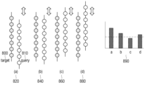
도 8 내지 도 10은 본 개시의 일 실시예에 따른, 노드 번들을 매칭하여 노드 시퀀스를 획득하는 방법을 설명하기 위한 도면이다.Figures 8 to 10 are diagrams for explaining a method of obtaining a node sequence by matching node bundles, according to an embodiment of the present disclosure.
도 8은 이동 로봇 장치(10)가 기존에 획득한 노드 번들(800)(또는, 타겟(Target))과 새로 획득한 노드 번들(810)(또는, 쿼리(query))의 거리 차이를 비교하면서 매칭 지점을 찾는 과정을 도시한 것이다.8 shows the
이동 로봇 장치(10)는 타켓(800)을 두고 쿼리(810)를 밀면서 에러 스코어(Error score)를 산출할 수 있다. 이동 로봇 장치(10)는 쿼리(810)의 위치를 계속 위로 올리면서 타켓(800)과의 거리 차이를 구하는 과정(820)을 반복할 수 있다. 따라서, (b)(840)나 (d)(880)의 경우보다, (c)의 경우가 타켓(800)과 쿼리(810)와 거리차이가 제일 작은 것을 표(890)를 통해 알 수 있다.The
도 9a에서는, 타켓_L(910)과 타켓_R(930) 한 쌍의 그래프 구조로 이루어진 노드 번들 그리고 쿼리_L(920)와 쿼리_R(940) 한 쌍의 그래프 구조로 이루어진 노드 번들을 도시하고 있다.In Figure 9a, a node bundle composed of a graph structure of a pair of Target_L (910) and Target_R (930) and a node bundle of a graph structure of a pair of Query_L (920) and Query_R (940) are shown. It is showing.
도 9b에서는, 타켓(800)이 쿼리(810)사이에 존재해서 이동 로봇 장치(10)가 각 노드 번들 사이의 물리값을 측정할 수 있는 범위에 있는지 여부를 표로 도시한 것이다.In FIG. 9B, a table shows whether the
도 9a에서 도시한 바와 같이, 이동 로봇 장치(10)는 쿼리_L(920)와 쿼리_R(940)을 기준으로 타켓_L(910)과 타켓_R(930) 의 거리 차이를 계산할 수 있다. 예를 들면, 이동 로봇 장치(10)는 쿼리_L(920)을 기준으로 타켓_L(920)과의 거리는 LL로 계산하고 쿼리_L(920)과 타켓_R(930)과의 거리는 LR로 계산할 수 있다.As shown in FIG. 9A, the
도 9b에서 도시한 바와 같이, 이동 로봇 장치(10)는 쿼리 번들이 좌측에 있든 우측에 있든 타켓 번들 사이에 있어야 쿼리 번들과 타켓 번들을 이루고 있는 그래프 구조간에 거리차이를 측정할 수 있다.As shown in FIG. 9B, the
도 10에서는 이동 로봇 장치(10)가 쿼리(1010)가 타켓(1020)사이에 존재하는 것으로 판단되면, 타켓(1020)은 쿼리만을 추출하고, 추출한 쿼리(1010)의 위치를 알아내기 위해 가우시안 프로세스를 이용하여 에러 스코어(Error Score)가 더 작은 타켓(1030)을 갱신하는 과정을 도시한 것이다.In FIG. 10, when the
이동 로봇 장치(10)는 타켓(1020) 사이에 존재하는 쿼리만을 추출하고 추출한 쿼리를 노드 시퀀스로 선정할 수 있다. 그리고, 이동 로봇 장치(10)는 노드 시퀀스의 위치를 알아내기 위해 기존의 타켓(1040)보다 더 쿼리와 거리 차이가 작은 타켓(1030)을 가우시안 프로세서(Gaussian process)를 이용하여 생성할 수 있다.The
이동 로봇 장치(10)는 노드 시퀀스로 선정된 커리와 거리 차이가 거의 없어질 때까지 즉, 거리 차이가 가장 작아질 때까지 가우시안 프로세서(Gaussian process)를 반복 수행하여 최종적으로 노드 시퀀스의 위치를 알아낼 수 있다.The
도 11은 본 개시의 일 실시예에 따른, 키노드와 노드 시퀀스를 이용하여 그래프 구조를 생성하는 방법을 설명하기 위한 도면이다.FIG. 11 is a diagram illustrating a method of generating a graph structure using key nodes and node sequences, according to an embodiment of the present disclosure.
이동 로봇 장치(10)는 3차원 이미지 데이터를 바탕으로 획득한 키노드(1100)와 센싱 데이터를 바탕으로 획득한 노드 시퀀스을 구성요소로 하는 그래프 구조(1110)를 구성하여 동시에 매칭을 할 수 있다.The
구체적으로, 이동 로봇 장치(10)는 키노드(1100)와 노드 시퀀스를 이용하여 구속조건(1120)를 만들수 있고, 루프 클루징(Loop closing)형태의 그래프 구조를 생성하여 그래프 슬램을 수행할 수 있다.Specifically, the
도 12 내지 도 13은 본 개시의 일 실시예에 따른, 이동 로봇 장치(10)가 위치 인식을 실패한 경우 그래프를 보정하는 방법을 설명하기 위한 도면이고, 도14 는 본 개시의 일 실시예에 따른, 이동 로봇 장치(10)가 위치 인식을 실패한 경우 그래프를 보정하는 방법을 설명하기 위한 흐름도이다.Figures 12 and 13 are diagrams for explaining a method for correcting a graph when the
휠 센서(160)가 이동 로봇 장치(10)가 들리는 키드내핑 상황 등 이동 로봇 장치(10)가 위치 인식을 실패하게 되는 경우를 감지 할 수 있고, 이때 이동 로봇 장치(10)는 다시 이미지 센서(110)와 복수의 지자기 센서(120)를 이용하여 키노드와 노드 시퀀스를 획득할 수 있다.The wheel sensor 160 can detect a case in which the
이동 로봇 장치(10)는 키드내핑과 같은 상황에서 똑같이 특징점이 누적되어 있는 서브맵을 기반으로 재배치 노드(Relocation Node)(1220)와 러프 매칭(Rough matching)을 할 수 있다.The
도 12a에 도시한 바와 같이 이동 로봇 장치(10)는 여러 서브맵 중에서 재배치 노드(1220)와 비교적 더 근접한 노드가 포함되어 있는 서브맵(1200)과 매칭할 수 있다. 그리고, 이동 로봇 장치(10)는 비교적 멀리 있는 노드가 포함되어 있는 서브맵(1210)은 재배치 노드(1220)와 매칭되지 않는 것으로 식별할 수 있다.As shown in FIG. 12A, the
그리고, 도 12b에서 도시한 바와 같이 이동 로봇 장치(10)는 재배치 노드(1220)와 더 근접한 노드가 포함되어 있는 서브맵(1200)과 다시 한번 매칭을 하여 제일 잘 매칭되는 짝을 탐색할 수 있다.And, as shown in FIG. 12B, the
도 13은 이동 로봇 장치(10)가 키드내핑(1300) 상황에서 가장 잘 매칭되는 짝 즉, 노드를 찾는 과정을 루프 클루징(Loop closing)된 그래프 구조에서 상세하게 도시한 것이다.FIG. 13 shows in detail the process of the
이동 로봇 장치(10)가 제일 잘 맞는 노드(1310)를 찾은 경우에는, 이동 로봇 장치(10)는 제일 잘 맞는 노드(1310)에 구속조건(Constraint)(1320)을 걸고 기존의 그래프 슬램을 수행한다.When the
도 14는 본 개시의 일 실시예에 따른, 이동 로봇 장치(10)가 위치 인식을 실패한 경우 그래프를 보정하는 방법을 설명하기 위한 흐름도이다.FIG. 14 is a flowchart illustrating a method for correcting a graph when the
우선, 휠 센서(160)는 이동 로봇 장치(10)가 들리는 등 키드내핑 상황을 감지할 수 있다.(S1410) 이때, 이동 로봇 장치(10)는 오도메트리 구속조건(Odometry constraint)의 생성을 중지할 수 있다.(S1420) 따라서, 이동 로봇 장치(10)는 회전을 하는 동시에, 이미지 센서(110)과 복수의 지자기 센서(120)를 이용하여 3차원 이미지 데이터와 센싱 데이터를 새롭게 획득할 수 있다.(S1430)First, the wheel sensor 160 can detect a kidnapping situation, such as the
그리고 이동 로봇 장치(10)는 획득한 새로운 3차원 이미지 데이터와 센싱 데이터를 바탕으로 키노드와 노드 시퀀스를 새롭게 획득하고, 재배치 노드와 매칭을 시도할 수 있다.(S1440)And the
이동 로봇 장치(10)는 매칭이 성공되는지 여부에 따라 다음 단계를 결정할 수 있다.(S1450) 이동 로봇 장치(10)는 매칭이 성공하지 않는 경우는 다시 매칭을 시도하고(S1440) 매칭이 성공하는 경우에는 매칭된 키노드와 노드 시퀀스를 바탕으로 그래프를 보정할 수 있다.(S1460)The
도 15는 본 개시의 일 실시예에 따른, 이동 로봇 장치(10)가 위치 인식을 실패했을 때를 가정하여 실험하는 방법 및 결과를 설명하기 위한 도면이다.FIG. 15 is a diagram illustrating a method and results of an experiment assuming that the
도 15a는, 가로 13m, 세로 8.5m인 직사각형 실험장에서 실험자가 이동 로봇 장치(10)에게 키드내핑 상황을(1510) 임의로 발생시켰을 때, 이동 로봇 장치(10)가 어떻게 작동하는지를 알기 위한 실험 방법을 도시하고 있다.FIG. 15A shows an experimental method to determine how the
도 15b에서 도 15a에서 계획한 실험을 실제 진행하였을 때의 결과값이 도시되어 있다. 점선으로 표시된 선(1520)은 키드내핑 상황에서 이동 로봇 장치(10)가 생성한 그래프 슬램의 궤적을 표시한 것이다. 그리고 실선으로 표시된 선은(1530)은 이동 로봇 장치(10)의 오도메트리 궤적으로, 키드내핑(1510)상황이 발생하였어도 그래프 슬램의 궤적(1520)에 맞게 결과값이 도출된 것을 알 수 있다.In Figure 15b, the results obtained when the experiment planned in Figure 15a was actually carried out are shown. The dotted
도 16은 본 개시의 일 실시예에 따른, 이동 로봇 장치(10)의 제어방법을 설명하기 위한 순서도이다.FIG. 16 is a flowchart for explaining a control method of the
우선, 이동 로봇 장치(10)는 이미지 센서(110)를 통해 복수의 이미지 데이터를 획득하고 복수의 지자기 센서(120)를 통해 센싱 데이터를 획득할수 있다.(S1610)First, the
그리고, 이동 로봇 장치(10)는 복수의 이미지 데이터에서 특징점을 추출하여 키노드를 획득하고, 센싱 데이터를 바탕으로 노드 시퀀스를 획득할 수 있다.(S1620)Then, the
그리고, 이동 로봇 장치(10)는 획득한 키노드와 노드 시퀀스를 이용하여 이동 로봇 장치(10)의 위치 정보를 나타내는 그래프 구조를 생성할 수 있다.(S1630)Then, the
그리고, 이동 로봇 장치(10)가 위치 인식을 실패하는 경우(예를 들면, 키드내핑과 같은 상황)에는(S1640) 다시 새롭게 키노드와 노드 시퀀스를 획득하여 이동 로봇 장치(10)의 위치 정보를 나타내는 그래프 구조를 보정할 수 있다.(S1650)And, if the
한편, 본 개시에서 사용된 용어 "부" 또는 "모듈"은 하드웨어, 소프트웨어 또는 펌웨어로 구성된 유닛을 포함하며, 예를 들면, 로직, 논리 블록, 부품, 또는 회로 등의 용어와 상호 호환적으로 사용될 수 있다. "부" 또는 "모듈"은, 일체로 구성된 부품 또는 하나 또는 그 이상의 기능을 수행하는 최소 단위 또는 그 일부가 될 수 있다. 예를 들면, 모듈은 ASIC(application-specific integrated circuit)으로 구성될 수 있다.Meanwhile, the term "unit" or "module" used in the present disclosure includes a unit comprised of hardware, software, or firmware, and may be used interchangeably with terms such as logic, logic block, component, or circuit, for example. You can. A “part” or “module” may be an integrated part, a minimum unit that performs one or more functions, or a part thereof. For example, a module may be comprised of an application-specific integrated circuit (ASIC).
본 개시의 다양한 실시예들은 기기(machine)(예: 컴퓨터)로 읽을 수 있는 저장 매체(machine-readable storage media)에 저장된 명령어를 포함하는 소프트웨어로 구현될 수 있다. 기기는, 저장 매체로부터 저장된 명령어를 호출하고, 호출된 명령어에 따라 동작이 가능한 장치로서, 개시된 실시예들에 따른 전자 장치를 포함할 수 있다. 명령이 프로세서에 의해 실행될 경우, 프로세서가 직접, 또는 상기 프로세서의 제어 하에 다른 구성요소들을 이용하여 상기 명령에 해당하는 기능을 수행할 수 있다. 명령은 컴파일러 또는 인터프리터에 의해 생성 또는 실행되는 코드를 포함할 수 있다. 기기로 읽을 수 있는 저장매체는, 비일시적(non-transitory) 저장매체의 형태로 제공될 수 있다. 여기서, '비일시적'은 저장매체가 신호(signal)를 포함하지 않으며 실재(tangible)한다는 것을 의미할 뿐 데이터가 저장매체에 반영구적 또는 임시적으로 저장됨을 구분하지 않는다.Various embodiments of the present disclosure may be implemented as software including instructions stored in a machine-readable storage media (e.g., a computer). The device is a device capable of calling instructions stored from a storage medium and operating according to the called instructions, and may include an electronic device according to the disclosed embodiments. When an instruction is executed by a processor, the processor may perform the function corresponding to the instruction directly or using other components under the control of the processor. Instructions may contain code generated or executed by a compiler or interpreter. A storage medium that can be read by a device may be provided in the form of a non-transitory storage medium. Here, 'non-transitory' only means that the storage medium does not contain signals and is tangible, and does not distinguish whether the data is stored semi-permanently or temporarily in the storage medium.
일시예에 따르면, 본 문서에 개시된 다양한 실시예들에 따른 방법은 컴퓨터 프로그램 제품(computer program product)에 포함되어 제공될 수 있다. 컴퓨터 프로그램 제품은 상품으로서 판매자 및 구매자 간에 거래될 수 있다. 컴퓨터 프로그램 제품은 기기로 읽을 수 있는 저장 매체(예: compact disc read only memory (CD-ROM))의 형태로, 또는 어플리케이션 스토어(예: 플레이 스토어TM)를 통해 온라인으로 배포될 수 있다. 온라인 배포의 경우에, 컴퓨터 프로그램 제품의 적어도 일부는 제조사의 서버, 어플리케이션 스토어의 서버, 또는 중계 서버의 메모리와 같은 저장 매체에 적어도 일시 저장되거나, 임시적으로 생성될 수 있다.According to one example, methods according to various embodiments disclosed in this document may be provided and included in a computer program product. Computer program products are commodities and can be traded between sellers and buyers. The computer program product may be distributed on a machine-readable storage medium (e.g. compact disc read only memory (CD-ROM)) or online through an application store (e.g. Play Store™). In the case of online distribution, at least a portion of the computer program product may be at least temporarily stored or created temporarily in a storage medium such as the memory of a manufacturer's server, an application store's server, or a relay server.
다양한 실시예들에 따른 구성 요소(예: 모듈 또는 프로그램) 각각은 단수 또는 복수의 개체로 구성될 수 있으며, 전술한 해당 서브 구성 요소들 중 일부 서브 구성 요소가 생략되거나, 또는 다른 서브 구성 요소가 다양한 실시예에 더 포함될 수 있다. 대체적으로 또는 추가적으로, 일부 구성 요소들(예: 모듈 또는 프로그램)은 하나의 개체로 통합되어, 통합되기 이전의 각각의 해당 구성 요소에 의해 수행되는 기능을 동일 또는 유사하게 수행할 수 있다. 다양한 실시예들에 따른, 모듈, 프로그램 또는 다른 구성 요소에 의해 수행되는 동작들은 순차적, 병렬적, 반복적 또는 휴리스틱하게 실행되거나, 적어도 일부 동작이 다른 순서로 실행되거나, 생략되거나, 또는 다른 동작이 추가될 수 있다.Each component (e.g., module or program) according to various embodiments may be composed of a single or multiple entities, and some of the above-described sub-components may be omitted or other sub-components may be used. It may be further included in various embodiments. Alternatively or additionally, some components (e.g., modules or programs) may be integrated into a single entity and perform the same or similar functions performed by each corresponding component prior to integration. According to various embodiments, operations performed by a module, program, or other component may be executed sequentially, in parallel, iteratively, or heuristically, or at least some operations may be executed in a different order, omitted, or other operations may be added. It can be.
100: 프로세서
110: 이미지 센서
120: 복수의 지자기 센서
130: 메모리
140: 주행부100: processor
110: image sensor
120: plural geomagnetic sensors
130: memory
140: Running unit
Claims (20)
주행부;
이미지 센서;
복수의 지자기 센서;
적어도 하나의 인스트럭션(instruction)을 저장하는 메모리; 및
상기 적어도 하나의 인스트럭션을 실행하는 프로세서;를 포함하고,
상기 프로세서는,
상기 이동 로봇 장치가 상기 주행부를 통해 이동하는 동안 상기 이미지 센서를 통해 복수의 이미지 데이터를 획득하고, 상기 복수의 지자기 센서를 통해 센싱 데이터를 획득하며,
상기 복수의 이미지 데이터로부터 특징점을 추출하고 상기 특징점을 바탕으로 키 노드들을 획득하고,
상기 센싱 데이터를 바탕으로 노드 시퀀스를 획득하고,
상기 키 노드들과 상기 노드 시퀀스를 바탕으로 상기 이동 로봇 장치의 위치를 추정하는 그래프 구조를 생성하고,
상기 이동 로봇 장치의 위치 인식을 실패할 경우 상기 그래프 구조의 생성을 중단하고, 상기 이미지 센서 및 상기 복수의 지자기 센서를 이용하여 복수의 이미지 데이터 및 복수의 센싱 데이터를 새롭게 획득하여 상기 키노드 및 상기 노드 시퀀스를 획득하고, 획득한 상기 키노드 및 상기 노드 시퀀스와 재배치 노드를 매칭하여 상기 그래프 구조를 보정하는 이동 로봇 장치.In the mobile robot device,
Running part;
image sensor;
a plurality of geomagnetic sensors;
a memory storing at least one instruction; and
Including a processor executing the at least one instruction,
The processor,
While the mobile robot device moves through the traveling unit, acquire a plurality of image data through the image sensor and acquire sensing data through the plurality of geomagnetic sensors,
Extracting feature points from the plurality of image data and obtaining key nodes based on the feature points,
Obtain a node sequence based on the sensing data,
Generating a graph structure that estimates the location of the mobile robot device based on the key nodes and the node sequence,
If the location recognition of the mobile robot device fails, the generation of the graph structure is stopped, and a plurality of image data and a plurality of sensing data are newly acquired using the image sensor and the plurality of geomagnetic sensors to detect the key node and the plurality of sensing data. A mobile robot device that acquires a node sequence and corrects the graph structure by matching the obtained key node and the node sequence with a relocation node.
상기 프로세서는,
상기 복수의 이미지 데이터에서 ORB(Oriented FAST and Rotated BRIEF)알고리즘을 이용하여 상기 특징점들을 추출하는 것을 특징으로 하는 이동 로봇 장치.According to clause 1,
The processor,
A mobile robot device, characterized in that the feature points are extracted from the plurality of image data using an ORB (Oriented FAST and Rotated BRIEF) algorithm.
상기 프로세서는,
상기 특징점들을 누적하여 서브맵을 구성하고,
상기 서브맵을 RANSAC(Random sample consensus) 알고리즘을 수행하고 가장 근접한 노드와 매칭하여 상기 키 노드를 획득하는 것을 특징으로 하는 이동 로봇 장치.According to clause 1,
The processor,
Construct a submap by accumulating the feature points,
A mobile robot device characterized in that the key node is obtained by performing a random sample consensus (RANSAC) algorithm on the submap and matching it with the closest node.
상기 프로세서는,
상기 획득한 센싱 데이터를 그룹핑하여 센싱 데이터 그룹을 획득하고,
상기 센싱 데이터 그룹의 자기장값과 기존에 저장한 센싱 데이터 그룹의 자기장값들을 비교하여 매칭하고,
상기 매칭된 센싱 데이터 그룹을 바탕으로 한 쌍의 그래프 구조로 이루어진 노드 번들을 획득하는 것을 특징으로 하는 이동 로봇 장치.According to clause 1,
The processor,
Obtain a sensing data group by grouping the obtained sensing data,
Compare and match the magnetic field values of the sensing data group with the previously stored magnetic field values of the sensing data group,
A mobile robot device characterized in that it acquires a node bundle consisting of a pair of graph structures based on the matched sensing data group.
상기 프로세서는,
기존에 저장된 노드 번들 사이에 새로 획득한 노드 번들이 존재하는 지 여부를 판단하고,
상기 기존에 저장된 노드 번들 사이에 상기 새로 획득한 노드 번들이 존재하는 것으로 판단되면, 상기 기존의 획득한 노드 번들 사이에 존재하는 상기 새로 획득한 노드 번들만을 추출하고,
상기 추출한 새로 획득한 노드 번들만을 상기 노드 시퀀스로 선정하는 것을 특징으로 하는 이동 로봇 장치.According to clause 4,
The processor,
Determine whether a newly acquired node bundle exists among existing stored node bundles,
If it is determined that the newly acquired node bundle exists between the previously stored node bundles, extracting only the newly acquired node bundle that exists between the existing acquired node bundles,
A mobile robot device, characterized in that only the extracted newly acquired node bundle is selected as the node sequence.
상기 프로세서는,
상기 추출한 새로 획득한 노드 번들과 거리 차이가 더 작은 기존의 획득한 노드 번들을 갱신하고,
상기 추출한 새로 획득한 노드 번들과 상기 갱신된 기존의 획득한 노드 번들 중 거리 차이가 가장 작은 노드 번들을 탐색하고,
상기 거리 차이가 가장 작은 노드 번들을 이용하여 상기 노드 시퀀스의 위치를 알아내는 것을 특징으로 하는 이동 로봇 장치.According to clause 5,
The processor,
Update the existing acquired node bundle with a smaller distance difference from the extracted newly acquired node bundle,
Search for the node bundle with the smallest distance difference between the extracted newly acquired node bundle and the updated existing acquired node bundle,
A mobile robot device characterized in that the location of the node sequence is determined using the node bundle with the smallest distance difference.
상기 프로세서는,
가우시안 프로세스(Gaussian process)를 이용하여 상기 거리 차이가 더 작은 기존의 획득한 노드 번들로 갱신하는 것을 특징으로 하는 이동 로봇 장치.According to clause 6,
The processor,
A mobile robot device characterized in that the distance difference is updated to an existing obtained node bundle using a Gaussian process.
상기 이동 로봇 장치가 이동하는 동안 이미지 센서를 통해 복수의 이미지 데이터를 획득하고, 복수의 지자기 센서를 통해 센싱 데이터를 획득하는 단계;
상기 복수의 이미지 데이터로부터 특징점을 추출하고 상기 특징점을 바탕으로 키 노드들을 획득하는 단계;
상기 센싱 데이터를 바탕으로 노드 시퀀스를 획득하는 단계;
상기 키 노드들과 상기 노드 시퀀스를 바탕으로 상기 이동 로봇 장치의 위치를 추정하는 그래프 구조를 생성하는 단계; 및
상기 이동 로봇 장치가 위치 인식을 실패할 경우 상기 그래프 구조의 생성을 중단하고, 상기 이미지 센서 및 상기 복수의 지자기 센서를 이용하여 복수의 이미지 데이터 및 복수의 센싱 데이터를 새롭게 획득하여 상기 키노드 및 상기 노드 시퀀스를 획득하고, 획득한 상기 키노드 및 상기 노드 시퀀스와 재배치 노드를 매칭하여 상기 그래프 구조를 보정하는 단계;를 포함하는 이동 로봇 장치의 제어방법.In the control method of a mobile robot device,
Obtaining a plurality of image data through an image sensor and acquiring sensing data through a plurality of geomagnetic sensors while the mobile robot device moves;
extracting feature points from the plurality of image data and obtaining key nodes based on the feature points;
Obtaining a node sequence based on the sensing data;
generating a graph structure for estimating the location of the mobile robot device based on the key nodes and the node sequence; and
If the mobile robot device fails to recognize the location, the generation of the graph structure is stopped, and a plurality of image data and a plurality of sensing data are newly acquired using the image sensor and the plurality of geomagnetic sensors to detect the key node and the plurality of sensing data. Obtaining a node sequence and correcting the graph structure by matching the obtained key node and the node sequence with a relocation node.
상기 키 노드들을 획득하는 단계는,
상기 복수의 이미지 데이터에서 ORB(Oriented FAST and Rotated BRIEF)알고리즘을 이용하여 상기 특징점들을 추출하는 이동 로봇 장치의 제어방법.According to clause 11,
The step of acquiring the key nodes is,
A control method for a mobile robot device that extracts the feature points from the plurality of image data using an ORB (Oriented FAST and Rotated BRIEF) algorithm.
상기 키 노드들을 획득하는 단계는,
상기 특징점들을 누적하여 서브맵(Submap)을 구성하는 단계;
상기 서브맵을 RANSAC(Random sample consensus) 알고리즘을 수행하고 가장 근접한 노드와 매칭하여 상기 키 노드를 획득하는 단계;를 포함하는 이동 로봇 장치의 제어방법.According to clause 11,
The step of acquiring the key nodes is,
Constructing a submap by accumulating the feature points;
Obtaining the key node by performing a random sample consensus (RANSAC) algorithm on the submap and matching it with the closest node.
상기 노드 시퀀스를 획득하는 단계는,
상기 획득한 센싱 데이터를 그룹핑하여 센싱 데이터 그룹을 획득하는 단계;
상기 센싱 데이터 그룹의 자기장값과 기존에 저장한 센싱 데이터 그룹의 자기장값들을 비교하여 매칭하는 단계; 및
상기 매칭된 센싱 데이터 그룹을 바탕으로 한 쌍의 그래프 구조로 이루어진 노드 번들을 획득하는 단계;를 포함하는 이동 로봇 장치의 제어방법.According to clause 11,
The step of obtaining the node sequence is,
Obtaining a sensing data group by grouping the obtained sensing data;
Comparing and matching the magnetic field values of the sensing data group with previously stored magnetic field values of the sensing data group; and
Obtaining a node bundle consisting of a pair of graph structures based on the matched sensing data group. A method of controlling a mobile robot device comprising a.
상기 노드 시퀀스를 획득하는 단계는,
기존에 저장된 노드 번들 사이에 새로 획득한 노드 번들이 존재하는 지 여부를 판단하는 단계;
상기 기존에 저장된 노드 번들 사이에 상기 새로 획득한 노드 번들이 존재하는 것으로 판단되면, 상기 기존의 획득한 노드 번들 사이에 존재하는 상기 새로 획득한 노드 번들만을 추출하는 단계; 및
상기 추출한 새로 획득한 노드 번들만을 상기 노드 시퀀스로 선정하는 단계;를 포함하는 이동 로봇 장치의 제어방법.According to clause 14,
The step of obtaining the node sequence is,
determining whether a newly acquired node bundle exists among existing stored node bundles;
If it is determined that the newly acquired node bundle exists between the previously stored node bundles, extracting only the newly acquired node bundle that exists between the previously stored node bundles; and
A control method for a mobile robot device comprising: selecting only the newly extracted node bundle as the node sequence.
상기 노드 시퀀스의 위치를 알아내는 단계는,
상기 추출한 새로 획득한 노드 번들과 거리 차이가 더 작은 기존의 획득한 노드 번들을 갱신하는 단계;
상기 추출한 새로 획득한 노드 번들과 상기 갱신된 기존의 획득한 노드 번들 중 거리 차이가 가장 작은 노드 번들을 탐색하는 단계; 및
상기 거리 차이가 가장 작은 노드 번들을 이용하여 상기 노드 시퀀스의 위치를 알아내는 단계;를 포함하는 이동 로봇 장치의 제어방법.According to clause 15,
The step of finding the location of the node sequence is,
updating an existing acquired node bundle with a smaller distance difference from the extracted newly acquired node bundle;
searching for a node bundle with the smallest distance difference between the extracted newly acquired node bundle and the updated existing acquired node bundle; and
A method of controlling a mobile robot device comprising: finding the location of the node sequence using a node bundle with the smallest distance difference.
상기 노드 시퀀스의 위치를 알아내는 단계는,
가우시안 프로세스(Gaussian process)를 이용하여 상기 거리 차이가 더 작은 기존의 획득한 노드 번들로 갱신하는 이동 로봇 장치의 제어방법.According to clause 16,
The step of finding the location of the node sequence is,
A control method for a mobile robot device that updates the previously obtained node bundle with a smaller distance difference using a Gaussian process.
Priority Applications (2)
| Application Number | Priority Date | Filing Date | Title |
|---|---|---|---|
| US17/055,415 US12001218B2 (en) | 2018-06-22 | 2019-06-21 | Mobile robot device for correcting position by fusing image sensor and plurality of geomagnetic sensors, and control method |
| PCT/KR2019/007499 WO2019245320A1 (en) | 2018-06-22 | 2019-06-21 | Mobile robot device for correcting position by fusing image sensor and plurality of geomagnetic sensors, and control method |
Applications Claiming Priority (2)
| Application Number | Priority Date | Filing Date | Title |
|---|---|---|---|
| US201862688700P | 2018-06-22 | 2018-06-22 | |
| US62/688,700 | 2018-06-22 |
Publications (2)
| Publication Number | Publication Date |
|---|---|
| KR20200010988A KR20200010988A (en) | 2020-01-31 |
| KR102601141B1 true KR102601141B1 (en) | 2023-11-13 |
Family
ID=69369426
Family Applications (1)
| Application Number | Title | Priority Date | Filing Date |
|---|---|---|---|
| KR1020190024283A Active KR102601141B1 (en) | 2018-06-22 | 2019-02-28 | mobile robots and Localization method using fusion image sensor and multiple magnetic sensors |
Country Status (2)
| Country | Link |
|---|---|
| US (1) | US12001218B2 (en) |
| KR (1) | KR102601141B1 (en) |
Families Citing this family (3)
| Publication number | Priority date | Publication date | Assignee | Title |
|---|---|---|---|---|
| EP4194881A1 (en) * | 2020-11-13 | 2023-06-14 | Naver Corporation | Deep smartphone sensors fusion for indoor positioning and tracking |
| CN113361539B (en) * | 2021-05-21 | 2024-07-02 | 煤炭科学技术研究院有限公司 | Instrument reading method and device of underground inspection robot and electronic equipment |
| KR20250087037A (en) * | 2023-12-07 | 2025-06-16 | 주식회사 쓰리아이 | System and method for correcting indoor positioning |
Citations (1)
| Publication number | Priority date | Publication date | Assignee | Title |
|---|---|---|---|---|
| JP2017045447A (en) * | 2015-08-28 | 2017-03-02 | パナソニック インテレクチュアル プロパティ コーポレーション オブ アメリカPanasonic Intellectual Property Corporation of America | Map generation method, self-position estimation method, robot system, and robot |
Family Cites Families (21)
| Publication number | Priority date | Publication date | Assignee | Title |
|---|---|---|---|---|
| AU2003264048A1 (en) | 2002-08-09 | 2004-02-25 | Intersense, Inc. | Motion tracking system and method |
| US8930023B2 (en) * | 2009-11-06 | 2015-01-06 | Irobot Corporation | Localization by learning of wave-signal distributions |
| KR100801261B1 (en) | 2006-11-03 | 2008-02-04 | 주식회사 에스씨티 | Control Method of Robot with Geomagnetic Sensor |
| KR101658578B1 (en) * | 2010-01-27 | 2016-09-22 | 삼성전자주식회사 | Apparatus and Method for calibration of composite sensor |
| JP2012064131A (en) | 2010-09-17 | 2012-03-29 | Tokyo Institute Of Technology | Map generating device, map generation method, movement method of mobile, and robot device |
| KR101913332B1 (en) * | 2011-12-23 | 2018-10-31 | 삼성전자주식회사 | Mobile apparatus and localization method of mobile apparatus |
| KR20140108821A (en) * | 2013-02-28 | 2014-09-15 | 삼성전자주식회사 | Mobile robot and method of localization and mapping of mobile robot |
| KR101988384B1 (en) | 2013-03-08 | 2019-06-12 | 삼성전자주식회사 | Image matching apparatus, image matching system and image matching mehod |
| JP6136543B2 (en) * | 2013-05-01 | 2017-05-31 | 村田機械株式会社 | Autonomous mobile |
| CN103278170B (en) * | 2013-05-16 | 2016-01-06 | 东南大学 | Based on mobile robot's cascade map creating method that remarkable scene point detects |
| CN103674015B (en) | 2013-12-13 | 2017-05-10 | 国家电网公司 | Trackless positioning navigation method and device |
| KR20170036657A (en) * | 2014-03-19 | 2017-04-03 | 뉴럴라 인코포레이티드 | Methods and apparatus for autonomous robotic control |
| US10379172B2 (en) | 2015-06-05 | 2019-08-13 | Irobot Corporation | Magnetic field localization and navigation |
| KR101730714B1 (en) * | 2015-06-12 | 2017-04-28 | 한국과학기술원 | Mobile robot estimation method and apparatus using geomagnetic field and bicubic interpolation |
| KR101738751B1 (en) * | 2015-06-22 | 2017-05-23 | 한국과학기술원 | Method and apparatus for localization of mobile robot using indoor magnetic field |
| KR101831028B1 (en) | 2015-07-03 | 2018-02-21 | 한국과학기술원 | Method and apparatus for relocation of mobile robot in indoor environment |
| KR102403504B1 (en) | 2015-11-26 | 2022-05-31 | 삼성전자주식회사 | Mobile Robot And Method Thereof |
| EP3252714A1 (en) | 2016-06-03 | 2017-12-06 | Univrses AB | Camera selection in positional tracking |
| KR102688528B1 (en) * | 2017-01-25 | 2024-07-26 | 엘지전자 주식회사 | Moving robot and control method therof |
| US10347001B2 (en) * | 2017-04-28 | 2019-07-09 | 8th Wall Inc. | Localizing and mapping platform |
| US10949798B2 (en) * | 2017-05-01 | 2021-03-16 | Symbol Technologies, Llc | Multimodal localization and mapping for a mobile automation apparatus |
-
2019
- 2019-02-28 KR KR1020190024283A patent/KR102601141B1/en active Active
- 2019-06-21 US US17/055,415 patent/US12001218B2/en active Active
Patent Citations (1)
| Publication number | Priority date | Publication date | Assignee | Title |
|---|---|---|---|---|
| JP2017045447A (en) * | 2015-08-28 | 2017-03-02 | パナソニック インテレクチュアル プロパティ コーポレーション オブ アメリカPanasonic Intellectual Property Corporation of America | Map generation method, self-position estimation method, robot system, and robot |
Also Published As
| Publication number | Publication date |
|---|---|
| KR20200010988A (en) | 2020-01-31 |
| US20210114204A1 (en) | 2021-04-22 |
| US12001218B2 (en) | 2024-06-04 |
Similar Documents
| Publication | Publication Date | Title |
|---|---|---|
| Walch et al. | Image-based localization using lstms for structured feature correlation | |
| JP7203769B2 (en) | Voxel-based ground plane estimation and object segmentation | |
| Peng et al. | Globally-optimal contrast maximisation for event cameras | |
| US10939791B2 (en) | Mobile robot and mobile robot control method | |
| Ito et al. | W-rgb-d: floor-plan-based indoor global localization using a depth camera and wifi | |
| Ding et al. | Vehicle pose and shape estimation through multiple monocular vision | |
| Saleem et al. | Neural network-based recent research developments in SLAM for autonomous ground vehicles: A review | |
| US11703334B2 (en) | Mobile robots to generate reference maps for localization | |
| CN110874100A (en) | System and method for autonomous navigation using visual sparse maps | |
| KR102629036B1 (en) | Robot and the controlling method thereof | |
| WO2019057179A1 (en) | Visual slam method and apparatus based on point and line characteristic | |
| CN114187418A (en) | Loop detection method, point cloud map construction method, electronic device and storage medium | |
| CN110335337A (en) | An Approach to Visual Odometry Based on End-to-End Semi-Supervised Generative Adversarial Networks | |
| US11562524B2 (en) | Mobile robots to generate occupancy maps | |
| KR102601141B1 (en) | mobile robots and Localization method using fusion image sensor and multiple magnetic sensors | |
| Ishihara et al. | Deep radio-visual localization | |
| Dong et al. | R-LIOM: Reflectivity-aware LiDAR-inertial odometry and mapping | |
| Li et al. | A neuro-inspired visual SLAM approach using AKAZE feature extraction in complex and dynamic environments | |
| Su et al. | An efficient human-following method by fusing kernelized correlation filter and depth information for mobile robot | |
| Lv et al. | So-pfh: Semantic object-based point feature histogram for global localization in parking lot | |
| Wang et al. | Simultaneous clustering classification and tracking on point clouds using Bayesian filter | |
| Vokhmintcev et al. | Real-time visual loop-closure detection using fused iterative close point algorithm and extended Kalman filter | |
| CN116539025A (en) | Method, equipment and medium for updating agent navigation map | |
| Deng et al. | Semantic-pixel associative information improving loop closure detection and experience map building for efficient visual representation | |
| US12620109B2 (en) | Learning reliable keypoints in situ with introspective self-supervision |
Legal Events
| Date | Code | Title | Description |
|---|---|---|---|
| PA0109 | Patent application |
Patent event code: PA01091R01D Comment text: Patent Application Patent event date: 20190228 |
|
| PG1501 | Laying open of application | ||
| A201 | Request for examination | ||
| PA0201 | Request for examination |
Patent event code: PA02012R01D Patent event date: 20220221 Comment text: Request for Examination of Application Patent event code: PA02011R01I Patent event date: 20190228 Comment text: Patent Application |
|
| E902 | Notification of reason for refusal | ||
| PE0902 | Notice of grounds for rejection |
Comment text: Notification of reason for refusal Patent event date: 20230724 Patent event code: PE09021S01D |
|
| E701 | Decision to grant or registration of patent right | ||
| PE0701 | Decision of registration |
Patent event code: PE07011S01D Comment text: Decision to Grant Registration Patent event date: 20231012 |
|
| GRNT | Written decision to grant | ||
| PR0701 | Registration of establishment |
Comment text: Registration of Establishment Patent event date: 20231107 Patent event code: PR07011E01D |
|
| PR1002 | Payment of registration fee |
Payment date: 20231108 End annual number: 3 Start annual number: 1 |
|
| PG1601 | Publication of registration |